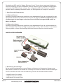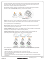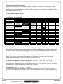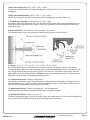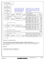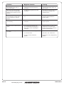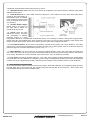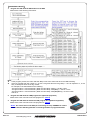
1
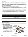
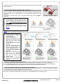
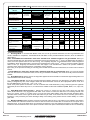
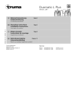
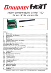
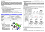
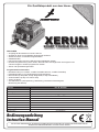
r fü Ein Qualitätsprodukt aus dem Hause re n t s ei ne ah se t k ig J ie is e 4 D kt ge b 1 u g, r a od eu tle Pr elz or i p Sp ells od M n. XERUN SHORT COURSE Pro Edition FEATURES • Ausgelegt für BL-Motoren mit & ohne Sensor • Speziell für Short-Course-Modelle abgestimmte Software • Sauberes Anlauf- und lineares Regelverhalten • Getaktetes BEC • Die Firmware kann über den USB-Anschluss aktualisiert werden • Einfache Programmierung durch Taster, alternativ kann der Regler über die Program Card oder die Program LCD Box programmiert werden • Staub- und spritzwassergeschützt Programmierbare Parameter • Betriebsmodus (nur vorwärts, vorwärts-rückwärts-bremse, vorwärts-rückwärts) • Rückwärtsmodus in vier Leistungsstufen programmierbar • Bremsmodus (5 Step ABS, 8 Step Drag Brake, 4 Step Initial Brake) • Anlaufverhalten (9 Step von soft bis hart) • Timing, 8 Stufen • Schutzfunktionen (Unterspannung, Überhitzung, Verlust des Sendersignals, Blockierung des Motors) Reglertyp Dauerlast Kurzzeitiger Spitzenstrom Einsatzbereich Passende Motoren mit 2s LiPo Passende Motoren 3s LiPo Passende Motoren 4s LiPo Zellenzahl NiMH Zellenzahl LiPo BEC-Spannung Abmessungen Best.-Nr. 81020260 120A 760A 1/10 & 1/8 SC / Buggy / Truggy / Monster Truck <6000KV <4000KV <3000KV 6-12 Zellen 2-4s 6,0V / 3,0A 53,5x36x36mm Bedienungsanleitung Instruction Manual Vor der ersten Inbetriebnahme, die Anleitung sorgfältig durchlesen! Beachten Sie unbedingt die Sicherheitshinweise! Bewahren Sie diese Dokumentation an einem sicheren Ort auf! Die Abkürzung BEC steht für “Battery Eliminator Circuit”. Durch diesen integrierten Schaltkreis wird der Empfänger aus dem Antriebsakku versorgt. Dadurch ist kein separater Empfängerakku erforderlich. Die EZRUN-Regler verfügen über ein getaktetes BEC. Der Ferritkern im Empfängerkabel, MUSS unbedingt verwendet werden, um Störungen der RC-Anlage zu vermeiden! 1. Anschluss der Komponenten 1.1 Motor mit Sensor Schließen Sie alle Komponenten gemäß der unten abgebildeten Skizze an und stecken Sie das Sensorkabel des Motors auf den Sensor-Anschluss des Reglers. WICHTIG: Verbinden Sie nun die Motorkabel mit dem Regler und achten Sie auf die Bezeichnungen #A #B und #C an Motor und Regler! 1.2 Motor ohne Sensor Schließen Sie alle Komponenten gemäß der unten abgebildeten Skizze an, die Motorkabel können in beliebiger Reihenfolge am Regler angeschlossen werden. Sollte der Motor in der falschen Richtung drehen, müssen zwei beliebige Kabel des Motors am Regler vertauscht werden. ANSCHLUSS-DIAGRAMM 2. Einstellung des Gaswegs Bei der ersten Inbetriebnahme muss der Regler zunächst an den Gasweg des Senders angepasst werden. Stellen Sie am Sender die Trimmung auf neutral und setzen Sie alle Einstellungen wie ATV oder EPA auf 100%. Bei der Kalibrierung müssen drei Punkte bestimmt werden: • Vollgas-Position für vorwärts • Vollgas-Position für rückwärts • Neutralpunkt für Leerlauf (Aus) Seite 2 www.hobbywing.com.de EZRUN Serie A) Regler ausschalten, Sender einschalten und die Laufrichtung des Gas-Kanals am Sender auf Reverse stellen, die Werte für EPA & ATV auf 100% setzen. Sollte der Sender über eine ABS-Funktion verfügen, muss(!) diese ausgeschaltet sein. B) SET-Taster am Regler drücken und gedrückt halten, gleichzeitig den Regler einschalten. Danach den SET-Taster SOFORT loslassen, sobald die rote LED blinkt. Hinweis: Wird der SET-Taster zu lange gehalten, gelangt man in den Programmiermodus des Reglers. In diesem Falle den Taster loslassen und die Schritte A) bis D) erneut ausführen. C) Nun werden die drei Punkte gespeichert: Neutral-Punkt: Gashebel in die Neutral-Position bewegen und gleichzeitig einmal den SETTaster drücken, die grüne LED blinkt einmal. Vollgas-Vorwärts-Punkt: Gashebel in die Vollgas-Vorwärts-Position bewegen und gleichzeitig einmal den SET-Taster drücken, die grüne LED blinkt zweimal. Vollgas-Rückwärts-Punkt: Gashebel in die Vollgas-Rückwärts-Position bewegen und gleichzeitig einmal den SET-Taster drücken, die grüne LED blinkt dreimal. D) Der Gasweg ist nun kalibriert, nach drei Sekunden ist der Regler jetzt scharf geschaltet! 3. Status der LED • Wenn der Gashebel in Leerlaufposition steht, sind beide LEDs aus. • Die rote LED leuchtet, wenn der Motor sich vorwärts oder rückwärts dreht, während des Bremsens blinkt die LED. • Die grüne LED leuchtet auf, wenn der Gashebel in die Vollgas-Position für vorwärts/rückwärts bewegt wird. EZRUN Serie www.hobbywing.com.de Seite 3 4. Einstellung der LiPo-Parameter Wenn Sie Ihren Regler mit LiPo-Akkus betreiben, müssen die Parameter für die LiPo-Zellen korrekt eingestellt werden, um eine Tiefentladung der Zellen zu verhindern. Beim Einschalten des Reglers ertönen Beep-Signale, um die Anzahl der Zellen zu signalisieren (Beep-Beep für 2s, Beep-Beep-Beep für 3s usw.). 5. Programmierung des Reglers 5.1 Übersicht der Parameter Programmable Items 1 2 Forward withBrake Forward/Reverse with Brake Programmable Value 3 4 5 6 7 8 9 60% 3.4V /Cell Level6 80% 100% Level7 Level8 15.00 ° 18.75° 22.50° 26.25° Basic Items 1.RunningMode Forwardand Reverse 0% 5% 10% Non-Protection 2.6V/Cell 2.8V/Cell Level1 Level2 Level3 5.MaxBrakeForce 25% 50% 6.MaxReverseForce 25% 50% 7.InitialBrakeForce = Drag Brake Force 0% 20% 40% 6%(Narrow) 9% (Normal) 12%(Wide) 0.00° 3.75° 7.50° 11.25° 3Cells 4Cells 2.DragBrakeForce 3.LowVoltage Cut-OffThreshold 4.StartMode(Punch) 20% 3.0V /Cell Level4 40% 3.2V /Cell Level5 75% 100% Disable 75% 100% Level9 Advanced Items 8.NeutralRange 9.Timing (Onlyforsensorless motor) 10.Over-heatProtection 11.MotorRotation 12.LipoCells Enable Disable Counter Clockwise Clockwise Auto Calculate 2Cells 1. Running Mode: Vorwärts mit Bremse / *Vorwärts & Rückwärts mit Bremse / Vorwärts & Rückwärts Dieser Menüpunkt legt fest, welche Betreisbarten verfügbar sind. Hinweis: Um die Rückwärtsfunktion zu aktivieren, muss der Gashebel dreimal ganz nach vorn geschoben werden. Erst beim dritten Mal, schaltet der Motor auf rückwärts. Diese Funktion schützt den gesamten Antrieb vor Überlastung! 2. Drag Brake Force: 0% / 5% / *10% / 20% / 40% / 60% / 80% / 100% Dieser Wert legt die Bremswirkung fest, wenn der Gashebel auf neutral steht. Das Modell bremst dann automatisch, sowie der Gashebel auf neutral steht. 3. Unterspannungsschutz (Spannungsgrenze): *Aus / 2,6V / 2,8V / 3,0V / 3,2V / 3,4V Diese Funktion verhindert eine Tiefentladung der LiPo-Akkus. Wenn der eingestellte Wert für zwei Sekunden unterschritten wird, wird die Motorleistung um 70% reduziert, nach 10 Sekunden wird der Motor komplett abgeschaltet und die rote LED blinkt. 4. Motoranlauf: Level 1 ... *Level 7 ... Level 9 Im Regler kann festgelegt werden, wie hart der Motor beschleunigt wird. Mit Level 1 läuft der Motor sehr weich an und schont den Antrieb. Auf Level 9 reagiert der Motor sehr direkt. je höher der Level, desto höher auch die Ströme und desto höher auch der Verschleiß im Antriebsstrang. Seite 4 www.hobbywing.com.de EZRUN Serie 5. Max. Bremsleistung: 25% / 50% / 75% / *100% Der Regler verfügt über eine Proportional-Bremse. Mit dem Wert wird die maximale Bremskraft festgelegt. 6. Max. Rückwärtsleistung: 25% / *50% / *75% / 100% Dieser Wert legt fest, wieviel Leistung beim Rückwärtsfahren maximal möglich ist. 7. Initial-Bremsleistung: *Drag Brake / 0% / 20% / 40% Mit diesem Wert wird festgelegt wie hoch die Bremswirkung am Anfang des Bremsbereichs ist. Diese Bremsleistung kommt zum tragen, sowie der Gashebel an den Anfang der Bremszone geschoben wird. 8. Neutral-Bereich: 6% (schmal) / *9% (normal) / 12% (weit) Der Neutral-Bereich kann von schmal bis weit gewählt werden (siehe Skizze). 9. Timing: 0°/ 3,75° / 7,5° / 11,25° / *15° / 18,75° / 22,5° / 26,25° Die Timing-Werte können für Motoren mit und ohne Sensor eingestellt werden. Der exakte Timingwert muss jedoch auf den jeweiligen Motor individuell angepasst werden. Mit dem korrekten Timing läuft der Motor weich und ruckelfrei. Je höher der Timingwert, desto höher sind die Motorleistung und die Motordrehzahl. Hinweis: Nach jeder Veränderung des Timings muss der Motorlauf vor dem Start des Modells getestet werden! 10. Temperaturschutz: *Aktiviert / Deaktiviert Der Regler verfügt über einen Temperaturschutz. Übersteigt die Temperatur im Regler oder im Brushless-Motor (nur mit Sensor) den maximal zulässigen Wert für mehr als fünf Sekunden, so wird der Motor abgeschaltet und die grüne LED blinkt. 11. Motorlaufrichtung: *Gegen Uhrzeigersinn / Im Uhrzeigersinn Mit diesem Menüpunkt kann die Motorlaufrichtung umgekehrt werden. 12. Anzahl LiPo-Zellen: *Auto / 2s / 3s / 4s In diesem Parameter legen Sie fest, wieviele Zellen der eingesetzte LiPo-Akku hat. Bei Wahl von Auto, wird die Zellenzahl automatisch aus der Akkuspannung errechnet. EZRUN Serie www.hobbywing.com.de Seite 5 6. Methoden zur Programmierung des Reglers A) Programmierung des Reglers mit der Program Card (86020010) Bitte beachten Sie die Hinweise in der Anleitung zu der Program Card. B) Programmierung des Reglers mit der Program Box (86020090) Bitte beachten Sie die Hinweise in der Anleitung zu der Program Box. C) Programmierung des Reglers mit der SET-Taste am Regler Bitte beachten Sie die nachfolgende Anleitung. Hinweis: Das Regleranschlusskabel (Verbindung zum Empfänger) kann NICHT für die Verbindung zur LED Program Card oder LCD Program Box verwendet werden um den Regler zu programmieren. Es muss der 3-polige Steckplatz zwischen Motoranschluss #A und #B verwendet werden. Normalerweise dient dieser Steckplatz zum Anschluss des Lüfters, zur Programmierung ziehen Sie den Anschlussstecker des Lüfters ab. Normally, this 3 pin port is used to connect cooling fan, when programming the ESC, please unplug the cooling fan connector. Achten Sie beim Anschluss der Program Box auf die Ausrichtung des Steckers , dieser muss parallel erfolgen. 7. Reset auf Werkseinstellungen Der Regler kann jederzeit auf die Werkseinstellungen zurückgesetzt werden, wenn sich der Gasknüppel in der Neutralposition befindet. Drücken Sie den SET-Taster für drei Sekunden, die rote und die grüne LED blinken gleichzeitig auf, alle Parameter sind nun auf Werkseinstellungen zurückgesetzt. 8. Warntöne 8.1 Unzulässige Eingangsspannung Nach dem Einschalten des Reglers wird die Eingangsspannugn des Akkus überprüft. Liegt diese außerhalb der zulässigen Werte ertönen folgende Signale: Beep-Beep, Beep-Beep, Beep-Beep... 8.2 Fehlerhaftes Empfängersignal Wenn der Regler kein gültiges Empfängersignal erhält, ertönen folgende Signale: Beep, Beep, Beep, Beep, Beep... Seite 6 www.hobbywing.com.de EZRUN Serie Hinweise zur Programmierung • Im Programmiermodus sendet der Regler zusätzlich zur LED ein Beep-Signal. • Wenn ein Wert größer als 5 vom Regler ausgegeben werden soll, dann werden die fünf kurzen Signale durch ein langes Signal (LED & Beep) ersetzt. So fällt es leichter den ausgegebenen Wert zu erfassen. Beispiele 1 langes Signal und ein kurzes Signal = 6 1 langes Signal und zwei kurze Signale = 7 EZRUN Serie www.hobbywing.com.de Seite 7 Seite 8 Problem Mögliche Ursache Lösung Keine Reaktion nach dem Anschluss des Akkus. Schlechter Kontakt der Steckerverbindungen. Steckerverbindungen prüfen und ggf. erneuern. Nach dem Anschluss des Akkus sendet der Motor ein Beep-BeepSignal in einem Intervall von einer Sekunde. Die Akkuspannung ist zu hoch oder zu niedrig. Überprüfen Sie die Akkuspannung und verwenden Sie ggf. einen zulässigen Akku. Nach dem Anschluss des Akkus sendet der Motor ein Beep-Signal in einem Intervall von zwei Sekunden. Der Regler erkennt kein Sendersignal. Geringe Reichweite der RCAnlage, Empfängerkabel des Reglers defekt. Der Motor dreht sich in der falschen Richtung. Motor falsch mit dem Regler verbunden. Zwei beliebige Motorkabel am Regler umpolen Der Motor bleibt im Betrieb einfach stehen. Der Unterspannungsschutz oder der Temperaturschutz im Regler ist aktiv oder es ist kein Sendersignal vorhanden. Betrieb einstellen und Akku erneut aufladen bzw. Temperatur des Reglers / Motors prüfen. Reichweite der RC-Anlage prüfen. Beim Gasgeben fängt der Motor an zu ruckeln. Falsche Getriebeübersetzung Kleineres Ritzel verwenden. Zu schwacher Akku Akku laden, bzw. austauschen. Zu hoher Level im Start Mode gewählt Niedrigeren Level im Regler-Setup wählen. www.hobbywing.com.de EZRUN Serie Sicherheitshinweise zu Lithium-Polymer-Akkus und Ladegeräten 1. Allgemein • Lithium-Polymer (kurz: LiPo) Akkus bedürfen besonderer Aufmerksamkeit • Fehlbehandlung bei Ladung und Entladung können zu Feuer, Rauchentwicklung, Explosionen und Vergiftung führen. • Die Nichtbeachtung von Anleitungs- und Warnhinweisen kann zu Leistungseinbußen oder sonstigen Defekten führen. • Die unsachgemäße Lagerung bei zu hohen oder zu niedrigen Temperaturen kann die Kapazität verringern. 2. Ladung • LiPo-Akkus stets nur auf einer nicht brennbaren, hitzebeständigen und nicht leitenden Unterlage laden. • Leicht entzündliche Gegenstände von der Ladeanordnung fernhalten. • Ladevorgang stets nur unter Aufsicht. • Nur das beiliegende oder ein von uns ausdrücklich zur Ladung des Akkus dieses Modells freigegebenes Ladegerät verwenden. • Spannungen von über 4,20 V pro Zelle führen zu dauerhafter Beschädigung der Zelle und können Feuer, Rauchentwicklung und Explosion zur Folge haben. • Akku nicht verpolen! Andernfalls laufen anormale chemische Reaktionen ab, die den Akku zerstören und sogar zu Feuer, Rauchentwicklung oder Explosion führen können. 3. Entladung • Der Entladestrom darf die vom Akkuhersteller vorgegebene C-Rate NICHT(!) überschreiten. • Nicht unter 2,5 V pro Zelle entladen, andernfalls wird Zelle dauerhaft geschädigt. • Betrieb sofort einstellen, wenn Leistung des Modells stark abfällt. • Kurzschlüsse und hohe Temperaturen (max. 70°C) vermeiden, da sonst Gefahr der Selbstentzündung des Akkus. 4. Beschädigung des Gehäuses und der Folie • Gehäusefolie vor Beschädigung durch scharfe Gegenstände schützen. • Beschädigungen der Folie machen den Akku unbrauchbar • Akku verformsicher in das Modell einbauen, auch im Falle eines Absturzes oder Crashs • Temperaturen über 70°C können das Gehäuse beschädigen, so dass Elektrolyt austreten kann. In diesem Fall wäre der Akku unbrauchbar und zu entsorgen. 5. Beschädigte Zellen • Keine Weiterverwendung von beschädigten Zellen ! • Kennzeichen beschädigter Zellen: Verformung, beschädigte Folie, Geruch oder Auslauf von Elektrolyten • Gesetzliche Entsorgungsvorschriften (Akku = Sondermüll) beachten 6. Warnhinweise • Nicht ins Feuer werfen ! • Nicht in Flüssigkeiten jeglicher Art eintauchen; jeglichen Kontakt mit Flüssigkeiten vermeiden. • Außerhalb der Reichweite von Kindern lagern. • Akku nicht demontieren, Gefahr von Feuer, Rauch und Explosion sowie Verätzungen. • Jeglichen Kontakt mit Elektrolyt vermeiden. Sofern doch Kontakt aufgetreten sein sollte, sofort mit viel frischem Wasser abspülen und den Arzt konsultieren. • Bei Nichtbenutzung des Modells den Akku immer entnehmen und vor Inbetriebnahme rechtzeitig aufladen. • Lagerung nur auf einer hitzebeständigen, nicht brennbaren und nicht leitenden Unterlage. • Tiefentladene Akkus nicht weiter verwenden. 7. Garantieausschluss • Da durch uns die richtige Ladung und Entladung des Akkus nicht überwacht werden kann, wird jegliche Garantie vorsorglich ausgeschlossen. 8. Haftungsausschluss • Da wir weder die Einhaltung der Montage- und Betriebsanleitung in Zusammenhang mit dem Modell, noch die Bedienung und Methoden bei Installation, Betrieb, Verwendung und Wartung des Modells nebst zugehöriger Elektronik überwachen können, übernehmen wir keinerlei Haftung für Verluste, Schäden oder Kosten, die sich aus der fehlerhaften Verwendung und dem Betrieb ergeben oder in irgendeiner Weise damit zusammenhängen. • Ausdrücklich lehnen wir auch jegliche Folgeschäden, die sich im Zusammenhang mit Installation, Betrieb, Verwendung und Wartung des Modells ergeben, ab. • Soweit vom Gesetzgeber nicht anders vorgeschrieben, ist unsere Verpflichtung zur Leistung von Schadenersatz – gleich aus welchem Rechtsgrund – auf den Rechnungswert der an dem schadenstiftenden Ereignis unmittelbar beteiligten Warenmenge begrenzt. Dies gilt nicht, sofern wir nach zwingenden gesetzlichen Vorschriften wegen Vorsatz oder grober Fahrlässigkeit unbeschränkt haften. HOBBYWING im Vertrieb der KYOSHO DEUTSCHLAND GMBH Nikolaus-Otto-Straße 4 D-24568 Kaltenkirchen Germany www.hobbywing.net EZRUN Serie www.hobbywing.com.de Seite 9 Garantiebedingungen § 1 Garantieerklärung (1) Wir übernehmen die Garantie, dass bei den Modellen und Bauteilen der Firma Hype während der Garantiefrist (§ 4) keine Fabrikationsoder Materialmängel zu Tage treten. (2) Diese Garantie gilt nur gegenüber Kunden, die ein Modell oder Bauteil der Firma Hype bei einem autorisierten Fachhändler in der Bundesrepublik Deutschland gekauft haben. Die Garantie ist nicht übertragbar. § 2 Ausschluss der Garantie (1) Keine Garantie besteht auf Verschleißteile wie Reifen, Felgen, Lager, Glühkerzen, Kupplungen, Lackierungen etc. (2) Die Garantie ist ferner ausgeschlossen, wenn - unzulässiges Zubehör verwandt worden ist oder Tuning- oder Anbauteile, die nicht aus dem Hype-Lieferprogramm stammen oder nicht von der Firma Hype ausdrücklich als zulässiges Zubehör deklariert worden sind. Es obliegt dem Käufer, sich bei seinem Hype-Fachhändler diesbezüglich zu informieren. - dritte Personen, welche nicht von der Firma Hype zu Service-Leistungen autorisiert wurden, Reparaturversuche oder sonstige Eingriffe in den Gegenstand vorgenommen haben, - die Bauanleitung oder Bedienungsanleitung missachtet, das Modell baulich verändert oder zweckentfremdet wurde oder - der Fehler auf lokale Verhältnisse des Kunden zurückzuführen ist. § 3 Hinweis auf gesetzliche Rechte (1) Diese Garantie wird von uns freiwillig und ohne gesetzliche Verpflichtung übernommen. (2) Wir weisen Sie darauf hin, dass Ihnen auch gesetzliche Rechte zustehen, wenn die von Ihnen gekaufte Sache bei Übergabe an Sie mangelhaft ist. Diese gesetzlichen Mängelrechte richten sich ausschließlich gegen Ihren Verkäufer, d.h. Ihren autorisierten Hype-Fachhändler. Nach dem Gesetz können Sie von Ihrem Verkäufer in erster Linie entweder die Reparatur der mangelhaften oder die Lieferung einer neuen Sache verlangen. Hierfür können Sie dem Verkäufer eine angemessene Frist setzen. Kommt der Verkäufer Ihrem Verlangen nicht nach, können Sie nach Ablauf der Frist den Vertrag rückabwickeln, d.h. die Sache zurückgeben und den Kaufpreis herausverlangen, oder eine angemessene Herabsetzung des Kaufpreises verlangen. Möglicherweise stehen Ihnen auch Schadensersatzansprüche zu, insbesondere, wenn der Verkäufer den Mangel kannte oder infolge von Fahrlässigkeit nicht kannte. (3) Die gegen die Firma Hype bestehenden Rechte aus dieser Garantie bestehen zusätzlich zu Ihren gesetzlichen Rechten und schränken diese Rechte in keiner Weise ein. § 4 Dauer der Garantie (1) Die Garantiefrist beträgt zwei Jahre und beginnt mit dem Tag des Kaufes bei Ihrem autorisierten Hype-Fachhändler. (2) Von uns erbrachte Garantieleistungen führen nicht zu einem Neubeginn oder einer Verlängerung der Garantiefrist. § 5 Rechte aus der Garantie (1) Liegt ein Garantiefall vor, werden wir die defekten Teile nach unserer Wahl austauschen oder reparieren. Austauschteile gehen in das Eigentum der Firma Hype über. (2) Die Garantieleistungen werden von der Firma Hype Serviceabteilung vorgenommen. (3) Die Material- und Arbeitskosten tragen wir. Falls das Gerät zum Zwecke der Prüfung und Reparatur transportiert wird, geschieht dies auf Ihre Gefahr und Ihre Kosten. (4) Weitergehende Ansprüche gegen uns, insbesondere auf Rückabwicklung des Vertrags, Herabsetzung des Kaufpreises oder Schadensersatz, bestehen aus dieser Garantie nicht. § 6 Geltendmachung der Garantie (1) Garantieansprüche sind unverzüglich nach Feststellung eines Material- oder Herstellungsfehlers bei einem autorisierten Hype-Fachhändler oder bei der Firma Hype, Serviceabteilung, Nikolaus-Otto-Straße 4, 24568 Kaltenkirchen, geltend zu machen. Für Defekte, die auf eine verzögerte Geltendmachung der Garantie zurückzuführen sind, übernehmen wir keine Garantie. (2) Zur Geltendmachung der Garantie ist die Vorlage eines Garantiebelegs und des beanstandeten Modells oder Bauteils erforderlich. Als Garantiebeleg gilt der Servicebegleitschein sowie auch der Verkaufsbeleg, wenn auf dem Verkaufsbeleg der Modelltyp mit der Bestellnummer vom autorisierten Hype-Fachhändler vermerkt ist und der Verkaufsbeleg mit Stempel, Datum und Unterschrift des Fachhändlers gegengezeichnet ist. (3) Modelle bzw. Teile sind in gereinigtem Zustand einzusenden (z.B. auch Benzintank völlig entleeren). Wir behalten uns vor, ungereinigte Teile auf Ihre Kosten zurückzusenden. (4) Stellt sich nach einer Prüfung des beanstandeten Modells oder Bauteils heraus, dass kein Garantiefall vorlag, sind wir berechtigt, den geleisteten Arbeitsaufwand nach unseren allgemeinen Stundensätzen, mindestens jedoch eine Aufwandspauschale in Höhe von € 8.50, zu berechnen. Seite 10 www.hobbywing.com.de EZRUN Serie Notizen EZRUN Serie www.hobbywing.com.de Seite 11 【DECLARATION】 Thanks for purchasing our Electronic Speed Controller (ESC). High power system for RC model can be very dangerous, so please read this manual carefully. In that we have no control over the correct use, installation, application, or maintenance of our products, no liability shall be assumed nor accepted for any damages, losses or costs resulting from the use of the product. Any claims arising from the operating, failure of malfunctioning etc. will be denied. We assume no liability for personal injury, consequential damages resulting from our product or our workmanship. As far as is legally permitted, the obligation to compensation is limited to the invoice amount of the affected product. 【FEATURES】 Suitable for 1/10th and 1/8th scale short course trucks and 1/8th scale buggies. Compatible with sensored and sensorless brushless motors, with the best control feelings. The built-in switching mode BEC has a powerful output to supply all electronic equipments even with 4S Lipo input. Excellent start-up, acceleration and linearity. Proportional ABS brake function with 5 steps of maximum brake force adjustment, 8 steps of drag-brake force adjustment and 4 steps of initial brake force adjustment. Also compatible with the mechanical disc-brake system. Multiple protection features: Low voltage cut-off protection / Over-heat protection / Throttle signal loss protection / Motor blocked protection Easily programmed with only one button and compatible with pocket-sized Program Card (Optional equipment) and the advanced LCD Program Box (Optional equipment). ESC firmware can be updated through an USB adapter on the LCD Program Box (Optional equipment). Splash proof and dust proof. 【SPECIFICATIONS】 Model Cont./Burst Current Suitable Motor Suitable Car Motor Turns Resistance Battery BEC Output Dimension Weight Note 1 If 2 side 2. In o to u the pro The tran A) B) Not in s XERUN-SCT PRO 120A / 760A Sensorless brushless motors 1/10th and 1/8th scale Truggy / Buggy ( Includes TRAXXAS 1/10th scale Truggy and buggy) 2S Lipo : KV≤6000 3S Lipo : KV≤4000 4S Lipo : KV≤3000 0.0004 ohm 6-12 cells Ni-xx (NiMH or NiCd) 2-4S Li-Po 6V/3A (Switching mode built-in BEC) 53.5(L) × 36(W) × 36(H) 99g C NOTE1 : The cooling fans of ESC is supplied by the built-in BEC, so it is always working under 6V . 【BEGIN TO USE THE NEW ESC】 WARNING! THIS BRUSHLESS SYSTEM IS VERY POWERFUL! FOR SAFETY, PLEASE ALWAYS KEEP THE WHEELS AWAY FROM THE TRACK WHEN YOU BEGIN TO SWITCH ON THE ESC. A) Sensored brushless motor wiring When using brushless motor with Hall Sensor, please connect the motor and the ESC with a sensor cable. WARNING! For sensored brushless motor, the #A, #B, #C wires of the ESC MUST be connected with the motor wire #A, #B, #C respectively. Do not change the wires sequence optionally! D 3. C ► ► ► B) Sensorless brushless motor wiring When using brushless motor without Hall Sensor, the #A, #B, #C wires of the ESC can be connected with the motor wires freely (without any sequence). If the motor runs in the opposite direction, please swap any two wire connections. Seite 12 www.hobbywing.com.de 4. C If you overIn no batte EZRUN Serie very ion, ses ning our the put. orce . on / and THE If 2 battery packs are connected in series, please take the wiring picture at the right side as reference. 2. Throttle Range Setting (Throttle Range Calibration) In order to make the ESC fit the throttle range, you must calibrate it when you begin to use a new ESC, or a new transmitter, or change the settings of neutral position of the throttle stick, ATV or EPA parameters, etc. Otherwise the ESC cannot work properly. The following pictures show how to set the throttle range with a FutabaTM transmitter. A) Switch off the ESC, turn on the transmitter, set the direction of throttle channel to ”REV”, set the “EPA/ATV” value of throttle channel to “100%”, and disable the ABS function of your transmitter. B) Hold the “SET” key and then switch on the ESC, and release the “SET” key as soon as possible when the red LED begins to flash. (Note2 ) Note2: If you don’t release the “SET” key as soon as the red LED begins to flash, the ESC will enter the program mode, in such a case, please switch off the ESC and re-calibrate the throttle range again from step A to step D. C) Set the 3 points according to the steps shown in the pictures on the right side. 1) The neutral point Move the throttle stick at the neutral point, and then click the SET key, the green LED flashes 1 time. 2) The end point of forward direction Move the throttle stick at the end point of forward direction, and then click the SET key, the green LED flashes 2 times. 3) The end point of backward direction Move the throttle stick at the end point of backward direction, and then click the SET key, the green LED flashes 3 times. D) Throttle range is calibrated; motor can be started after 3 seconds. 3. Check The LED Status In Normal Running ► Normally, if the throttle stick is located in the neutral range, neither the red LED nor the green LED lights. ► The red LED lights when the car is running forward or backward and it will flash quickly when the car is braking. ► The green LED lights when the throttle stick is moved to the top point of the forward zone. 4. Check The Lipo Cells Setting If You Are Using Lithium Battery If you are using Lipo battery, we strongly suggest setting the programmable item # 12 --- “Lipo Cells” manually to avoid the over-discharge problem. Please read the instructions on page 2. In normal case, when the ESC is switched on, the motor will emit several “Beep” tones to express the cells amount of the battery pack. For example, “Beep-Beep-” means 2S Lipo, “Beep-Beep-Beep-” means 3S Lipo, etc. EZRUN Serie www.hobbywing.com.de Seite 13 【PROGRAMMABLE ITEMS LIST】(The italics texts in the above form are the default settings) P ro g ra mm ab le P ro g ram m ab le V alue Ite ms 1 2 3 4 5 6 atrad 7 8 9 B as ic Ite m s Forward withBrake 1.R unningMode F or ward /Rev erse with Brake 1.7. locate theba value force, verys F orwardand Re vers e 2.D ragBrak eForce 0% 5% 10% 20% 3.Low Voltage C ut-O ffThreshold Non-Protec tion 2.6V/Cell 2.8V/Cell 3.0V /C ell 40% 3.2V /Ce ll 3.4V /Cell 60% 4.StartMod e(Punc h) Lev el1 Level2 Level3 Level4 L evel5 80% 100% Lev el6 Level7 Level8 Level9 6 7 8 9 (Continued with the form at page 1) Progra mm a ble Ite m s Progra mm a ble Value 3 4 5 1 2 5. Max Brak eF orc e 25% 50% 75% 100% 6. Max R evers eF orc e 25% 50% 75% 100% 40 % Adv a nce d It em s 7. Ini tial BrakeFo rce 8. Neut ralRange 9. Tim ing (O nly f ors ens orless m oto r) 10.O ver-he atProtec tio n 0% 20% 6% (N arrow) 9% (No rm a l) 12% (W ide) 0.00 ° 3.75 ° 7.50 ° 11.25° D isa ble 15.00 ° 18.75 ° 22. 50° 26.25° Co un ter Cl ockw i se Cloc k wis e A uto C alc ul ate 2 Cel ls 3C ells 1.8. Pleas the r neutra 1.9. differe and brush timing Pleas brings 1.10. power protec En abl e 11.Mot orR ot ation 12.LipoCells = Dr ag Br ake Fo rce 1.6. differe 4C ells Programmable Values 1.1. Running Mode:In “ForwardwithBrake”mode,thecarcangoforwardandbrake,butcannotgobackward,this modeissuitableforcompetition;“Forward/ReversewithBrake”modeprovidesbackwardfunction,whichissuitablefor dailytraining. Note: “Forward/Reverse with Brake” mode uses “Double-click” method to make the car go backward.Whenyou movethethrottlestickfromforwardzonetobackwardzoneforthefirsttime(The1st“click”),theESCbeginstobrakethe motor,themotorspeedsdownbutitisstillrunning,notcompletelystopped,sothebackwardactionisNOThappened immediately.Whenthethrottlestickismovedtothebackwardzoneagain(The2nd“click”),ifthemotorspeedisslowed down to zero (i.e. stopped), the backward action will happen. The “Double-Click” method can prevent mistakenly reversingactionwhenthebrakefunctionisfrequentlyusedinsteering. Bytheway,intheprocessofbrakingorreversing,ifthethrottlestickismovedtoforwardzone,themotorwillrunforward atonce. “Forward/Reverse” mode uses “Single-click” method to make the car go backward. Whenyoumovethethrottle stickfromforwardzonetobackwardzone,thecarwillgobackwardimmediately.ThismodeisusuallyusedfortheRock Crawler. 1.11. rearc setto 1.12. “Auto consid 2. R Atany hold t progra 1.2. Drag Brake Force: Settheamountofdragbrakeappliedatneutralthrottletosimulatetheslightbrakingeffectofa neutralbrushedmotorwhilecoasting. 1.3. Low Voltage Cut-Off: Thefunctionpreventsthelithiumbatterypackfromoverdischarging. TheESCdetectsthe battery’svoltageatanytime,ifthevoltageislowerthanthethresholdfor2seconds,theoutputpowerwillbecutoff,and theredLEDflashesinsuchaway:“☆-☆-, ☆-☆-, ☆-☆-”. Thereare6presetoptionsforthisitem.YoucancustomizethecutoffthresholdbyusingaLCDprogrambox(optional equipment)totrimitwithastepof0.1V,soitwillbemoresuitableforallkindsofbatteries(NiMH,NiCd,Li-ion,Lipo,LFP, etc). 1.4. Start Mode (Also called “Punch”): Selectfrom“Level1”to“Level9”asyourlike,Level1hasaverysoftstart effect,whilelevel9hasaveryaggressivestarteffect.FromLevel1toLevel9,thestartforceisincreasing.Pleasenote that if you choose “Level7” to “Level9” mode, you must use good quality battery pack with powerful discharge ability, otherwise these modes cannot get the burst start effect as you want. If the motor cannot run smoothly (the motor is trembling),itmaycausedbytheweakdischargeabilityofthebatterypack,pleasechooseabetterbatteryorasofter gearratio. 1.5. Maximum Brake Force: TheESCprovidesproportionalbrakefunction.Thebrakeforceisrelatedtotheposition ofthethrottlestick.Maximumbrakeforcereferstotheforce whenthethrottlestickislocatedattheend point ofthe backwardzone.Averylargebrakeforcecanshortenthebraketime,butitmaydamagethegears. The“Disable”option inhibitstheinherentbrakefunctionofthespeedcontroller.Whenthisoptionisselected,thebrakefunctionisrealizedby Seite 14 www.hobbywing.com.de EZRUN Serie atraditionalmechanicaldisc-brakesystemdrivenbyaservo. 1.6. Maximum Reverse Force:Setshowmuchpowerwillbeappliedinthereversedirection.Differentvaluemakes differentreversespeed. 9 1.7. Initial Brake Force: It is also called “minimum brake force”, and it refers to the force when the throttle stick is located at the initial position of thebackwardzone.Thedefault valueisequaltothedragbrake force,sothebrakeeffectcanbe verysmoothly. Level9 9 1.8. Throttle Neutral Range: Please refer to the picture on the right side to adjust the neutralrangeasyourlike. 1.9. Timing: There are many differences among structures and parameters of different brushless motors, so a fixed timingESCisdifficulttocompatiblewithallbrushlessmotors.Itisnecessarytomakethetimingvalueprogrammable. Pleaseselectthemostsuitabletimingvalueaccordingto themotoryouarejustusing.Generally,highertimingvalue bringsouthigherpoweroutput,butthewholeefficiencyofthesystemwillbeslightlylowerdown. 1.10. Over-Heat Protection: This function is permanently activatedby the factory, user cannot disable it. The output powerwillbecut-offwhenthetemperatureoftheESCishigherthanafactory-preset valuefor5seconds.Whenthe protectionhappens,theGreenLEDwillflashinsuchaway:“☆-, ☆-, ☆-”. rd,this blefor enyou akethe ppened slowed akenly orward 1.11. Motor Rotation: Youcanusethisitemtochangetherotationdirection.Facetothemotorshaft(Thatmeansthe rearcoverofthemotorisfarfromyourface),andmovethethrottlesticktothetoppointoftheforwardzone.Ifthisitemis setto“CCW”,theshaftrunscounter-clockwise.Ifthisitemissetto“CW”,theshaftrunsclockwise. 1.12. Lipo Cells: We strongly suggest setting the “Lipo Cells” item manually because sometimes the default setting “AutoCalculate”willcausemistake.Forexample,ifyouareusingadischarged4SLipobattery,theESCmaymistakenly consideritasafullycharged3SLipobattery,andthenthe“Lowvoltagecut-off”protectionfunctionwillbeinordinate. 2. Reset All Items To Default Values Atanytimewhenthethrottleislocatedinneutralzone(exceptinthethrottlecalibrationorparametersprogramprocess), hold the “SET” key for over 3 seconds, the red LED and green LED will flash at the same time , which means each programmableitemhasberesettoitsdefaultvalue. throttle eRock ectofa ctsthe off,and ptional o,LFP, ftstart enote ability, otor is softer osition ofthe option zedby EZRUN Serie www.hobbywing.com.de Seite 15 【PROGRAM THE ESC】 1. Program the ESC with the SET button on the ESC Please refer to the following instructions. 【T Af an Af bu ale a Af lig Th dir Th wh W m Note: ► In the program process, the motor will emit “Beep” tone at the same time when the LED is flashing. ► If the “N” is bigger than the number “5”, we use a long time flash and long “Beep---” tone to represent “5”, so it is easy to identify the items of the big number. For example, if the LED flashes as the following: “A long time flash + a short time flash” (Motor sounds “Beep---Beep”) = the No. 6 item “A long time flash + 2 short time flash” (Motor sounds “Beep---BeepBeep”) = the No. 7 item “A long time flash + 3 short time flash” (Motor sounds “Beep---BeepBeepBeep”) = the No. 8 item And so on. 2. Program the ESC with the LED program box (Optional equipment ) Please refer to the user manual of LED program box. (Note3) 3. Program the ESC with the advanced LCD program box (Optional equipment ) Please refer to the user manual of LCD program box. (Note3) Note3: The control wire of the ESC (for connecting receiver) CANNOT be used to connect with the LED Program Box or LCD Program Box to program this ESC. Seite 16 www.hobbywing.com.de EZRUN Serie W ne gr You must use the 3 pin port between the soldering terminal #A and #B. Normally, this 3 pin port is used to connect cooling fan, when programming the ESC, please unplug the cooling fan connector. Please also make sure that the 3 pin program port of the ESC must be connected ” in parallel, the cross with the Program Box through the port marked with “ connection is not correct. 【TROUBLE SHOOTING】【POWER SYSTEM SUGGESTIONS】 Trouble After power on, motor doesn’t work, and the cooling fan doesn’t work Possible Reason Solution The connections between Check the power connections battery pack and ESC are not Replace the connectors correct After power on, motor can’t work, Input voltage is abnormal, too Check the voltage of the battery pack but emits “beep-beep-, beep-beep-” high or too low alert tone. (Every “beep-beep-” has a time interval of 1 second ) After power on, red LED always Throttle signal is abnormal Plug the control wire into the throttle channel lights, the motor doesn’t work of the receiver correctly. The motor runs in the opposite direction when it is accelerated 1)The wire connections between ESC and the motor are not correct 2)The chassis is different from the popular design The motor suddenly stops running while in working state The throttle signal is lost When accelerating quickly, motor stops or trembles so it is the When the throttle stick is in the neutral range, the red LED and the green LED flashes synchronously EZRUN Serie The ESC has entered the Low Voltage Protection Mode or Over-heat Protection Mode 1) The battery has a bad discharge performance 2) Gear ratio is too aggressive 3) The “Start Mode (Punch)” of the ESC is too aggressive Over current protection, motor demagnetization, or motor is over load 1) For sensorless motor: Swap any two wire connections between the ESC and the motor. Or use the following method. 2) For sensored motor: Please check the wire connections, they must be A-A, B-B, C-C respectively. If the connections are correct, please change the “Motor Rotation” programmable item to “CW(Clockwise)” Check the transmitter and the receiver Check the signal wire from the throttle channel of your receiver Red LED flashing means Low Voltage. Green LED flashing means Over-heat 1) Use a better battery 2) Use lower KV motor or softer gear ratio 3) Set the “Start Mode (Punch)” to a softer value 1) Reduce the load (Use softer gear ratio or reduce the input voltage) 2) Change the motor www.hobbywing.com.de Seite 17 IMPORTANT SAFETY INSTRUCTIONS AND WARNINGS FOR LITHIUM-POLYMER-BATTERIES 1. General Guidelines and Warnings • LiPo batteries are NOT charged as you receive them. They contain approximately 50% of a full charge as recommended for shipment and long term storage . • Use Lithium Polymer specific chargers only. Do not use a NiCd or NiMh charger - Failure to do so may cause a fire, which may result in personal injury and property damage. • Never charge batteries unattended. When charging LiPo batteries you should always remain in constant observation to monitor the charging process and react to potential problems that may occur. • Some LiPo chargers on the market may have technical deficiencies that may cause them to charge LiPo batteries incorrectly. It is solely the responsibility of the user to assure that the charger used works properly. • If at any time you witness a battery starting to balloon or swell up, discontinue the charging process immediately. Disconnect the battery and place it in a safe observation area for approximately 15 minutes. Continuing to charge a battery that has begun to swell will result in fire. • Battery observation should occur in a safe area outside of any building or vehicle and away from any combustible material. The middle of a cement driveway is a good example of a safe observation area. • Shorts can cause fires! If you accidentally short the wires, the battery must be placed in a safe area for observation for approximately 15 minutes. Additionally, be mindful of the burn danger that may occur due to a short across jewelry (such as rings on your fingers). • Chemical reactions are not instantaneous, a battery that has been shorted may not ignite for 10 minutes. • All crash batteries, even if not deformed, should be placed in a safe area for observation for at least 15 minutes. • If for any reason you need to cut the terminal wires, cut each wire separately, ensuring the wires do not become shorted across the cutting tool. 2. Charging Process • Make a visual inspection of the pack. Checking for any damaged leads, connectors, broken/cracked shrink covering, puffiness or other irregularities. • Before installing or changing the connector, check the voltage of the pack using a digital voltmeter. All new packs ship at approximately 3.80V to 3.9V per cell. For example: A 2S pack should read approximately 7.60V to 7.8V, A 3S pack should read approximately 11.40V to 11.7V etc • If any damage to the pack or leads is found, or the voltage is significantly less for your pack than specified above, do not attempt to charge or fly the pack; contact AG Power directly as soon as possible. • Never charge batteries unattended. • Charge in an isolated area, away from flammable materials. • Let the battery cool down to ambient temperature before charging. • Do not charge battery packs in series. Charge each battery pack individually. Overcharging of one or the other battery may occur resulting in fire • When selecting the cell count or voltage for charging purposes, select the cell count and voltage as it appears on the battery label. Selecting a cell count or voltage other than the one printed on the label may result in overcharging and fire. As a safety precaution, please confirm that the information printed on the battery is correct. For example: If a battery label indicates that it is a 3 cell battery (3S), it's voltage should read between 11.4 and 11.7 volts. This battery must be charged as a 3 cell battery (peak of 12.6V). • You must check the pack voltage after each flight before re-charging. Do not attempt to charge any pack if the unloaded individual cell voltages are less than 3.3V. For example: Do not charge a 2-cell pack if below 6.6V Do not charge a 3 cell pack if below 9.9V • NORMAL CHARGING: The charge rate should not exceed 1C (one times the capacity of the battery, unless otherwise noted*). Higher setting may cause problems which can result in fire. For example: Charge a 730 mAh battery at or below 0.73Amps. Charge a 5000 mAh battery at or below 5Amps. 3. Storage & Transportation • Store batteries at room temperature • If storing longer than a couple of weeks; batteries should be stored at 3.8V/cell to 3.9V/cell (approximately 50% charged). • Do not expose battery packs to direct sunlight (heat) for extended periods. • When transporting or temporarily storing in a vehicle, temperature range s should be greater than 5c but no more than 35c • Storing Lipo batteries at temperatures greater than 40c for extended periods of time (more than 2 hours) may cause damage to battery and possible fire. 4. Caring for Battery • Only charge a LiPo battery with a good quality Lithium Polymer charger. A poor quality charger can be dangerous! • Set voltage and current correctly (failure to do so can cause fire). • Please check pack voltage after the first charge. For example; a 2 Cell battery should measure 8.4V (8.30 to 8.44), a 3 cell battery should measure 12.6V (12.45 to 12.66). • Do not discharge a battery to a level below 3V per cell under load. Discharging below 3V per cell can deteriorate battery performance. Be sure to set your ESC for the proper cut off voltage (6.0V cut off for 2S packs, 9.0V cut off for 3S packs, etc). • Use caution to avoid puncture of the battery. Puncturing a LiPo battery may cause a fire. • Always allow a battery to cool down to ambient temperature before re-charging. Batteries that lose 20% of their capacity must be removed from service and disposed of properly. Discharge the battery to 3V/Cell, making sure output wires are insulated, then wrap battery in a bag for disposal. Seite 18 www.hobbywing.com.de EZRUN Serie § 1 Warranty (1) We guarantee that there will be no production or material errors on Hype items during the guarantee period (§ 4) (2) The guarantee is valid for customers who bought Hype items over an authorized dealer. This guarantee cannot be transferred to another person. § 2 Exclusion of warranty (1) We do not grant any warranty on wastage parts like tires, wheels, bearings, glow plugs, clutch systems, paintings etc. (2) We also do not grant any warranty, if - non authorized accessory parts are used in the model, that are not produced by Hype or that are not clearly approved from Hype. - a third party, that is not authorized by Hype tries to repair or to modify the product. - the user disregards the instruction manual or modifies the model in a damaging way. - the error occurs because of local conditions where the model is used. § 3 Notification of legal rights (1) We grant this warranty on our products although we are not forced by law to do so. (2) Please note that you have also legal rights if an item is faulty when you buy it. In case of defects and a warranty claim you have to contact your local Hype dealer. According to the law you can ask your dealer to replace or to repair the faulty item. You can mention the dealer a reasonable deadline to do so. In case he does not manage within such a time period you can return the product to him and get your money back from him. (3) Your rights against the company Hype are additionally to your legal rights. § 4 Period of warranty (1) We grant you a 2 years warranty on all Hype products. This period starts when you buy the item at your local hobby shop. (2) In case of service feature the warranty period does not get extended. § 5 Your warranty rights (1) In case of warranty claim we will replace or repair the defective parts. The defective parts are property of Hype. (2) The warranty adjustment will be executed by the Hype service department. (3) We will cover the costs for material and man power. The risk and the costs of transportation are covered by the customer. (4) There are no further claims like annulling the sales contract, price reduction or compensation against us. § 6 Assertion of warranty claims (1) Any warranty claims have to be notified immediately after realizing an error. This can be done by your local hobby shop or directly to Hype, service department, Nikolaus-Otto-Straße 4, 24568 Kaltenkirchen, Germany. We do not cover any consecutive faults that occur because of a delayed notification. (2) For the assertion of a warranty claim you have to send us the defective part and a hardcopy of your invoice with the date of purchase. (3) All defective items have to be returned in a cleaned condition. Fuel tanks must be empty! In case parts are heavily contaminated we will return the parts on your costs! (4) in case the returned item is not defective and that there is no claim of warranty, we will charge you 8,50€ for our labor costs. EZRUN Serie www.hobbywing.com.de Seite 19 10/2011 Copyright by Hobbywing Technology Co.,Ltd Technische Änderungen sind ohne vorherige Ankündigungen möglich! Jeder Nachdruck, auch auszugsweise, bedarf unserer ausdrücklichen, schriftlichen Genehmigung. Hype • Nikolaus-Otto-Str. 4 • D-24568 Kaltenkirchen [email protected] • www.hype-rc.de • Helpdesk: 04191-932678