1
D
F
H
I
S
Bedienungsanleitung
Operating manual
Notice d‘emploi
Инструкции за експлоатация
Návod k obsluze
Οδηγίες χρήσεως
Kezelési utasítás
Istruzioni d’uso
Gebruiksaanwijzing
Instrukcja obsługi
Instrucţiuni de folosire
Användarhandbok
0
100M
10M
100k
AUTO SENSE
COMPARE
PI
DAR
100Gk
V
KMΩ
GΩ
µmA
100200
500KMΩ
RECALL
PI/DAR
STORE
LOCK
PASS
TEST
MΩ L
eak
Ω
a
ge
Cu
50 V 100 V 250 V
500 V
1000 V
en
rr
t
BENNING IT 101
10Gk
LOCK
V
COMP
100kM
V
OFF
TRUE RMS
V
Ω
> 660 V INSULATION
COM
FUSED
CAT.IV
600 V
DFHIS
0
100M
10M
100k
100kM
AUTO SENSE
10Gk
LOCK
V
V
DAR
100200
500KMΩ
RECALL
PI/DAR
STORE
LOCK
COMP
PASS
ge
Cu
50 V 100 V 250 V
500 V
1000 V
TEST
MΩ L
eak
a
en
rr
Ω
KMΩ
GΩ
µmA
COMPARE
PI
100Gk
t
V
OFF
TRUE RMS
V
Ω
> 660 V INSULATION
L
COM
M
CAT.IV
600 V
FUSED
N
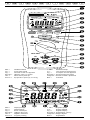
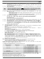
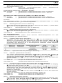
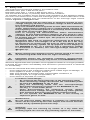
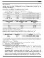
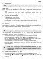
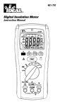
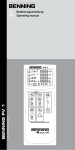
Bild 1:
Fig. 1:
Fig. 1:
фигура 1:
Obr. 1:
Εικόνα 1:
Gerätefrontseite
Front tester panel
Panneau avant de l‘appareil
Преден панел на уреда
Čelní strana přístroje
Εμπρόσθια πρόσοψη συσκευής
A
1. ábra: Készülék előlap
Ill. 1:
Lato anteriore apparecchio
Fig. 1:
Voorzijde van het apparaat
Rysunek 1: Panel przedni przyrządu
Imaginea 1:Partea frontală a aparatului
Bild 1: Framsida
B
C
D
F
S
0
R
100k
100M
10M
100kM
AUTO SENSE
10Gk
LOCK
P
V
O
N
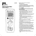
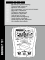
Displayanzeige
Digital display
Écran numérique
Цифров дисплей
Digitální zobrazení
Ψηφιακή ένδειξη
02/ 2011
M
COMPARE
PI
L
DAR
100Gk
V
KMΩ
Q
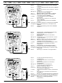
Bild 2:
Fig. 2:
Fig. 2:
фигура 2:
Obr. 2:
Εικόνα 2:
E
GΩ
µmA
100200
500KMΩ
K
J
2. ábra: Digitális kijelző
Ill. 2:
Display digitale
Fig. 2:
Digitaal display
Rysunek 2: Wyświetlacz cyfrowy
Imaginea 2:Afişajul digital
Bild 2: Digitalskärm
BENNING IT 101
G
H
I
DFHIS
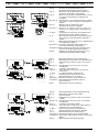
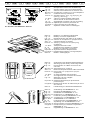
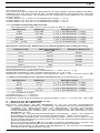
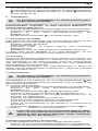
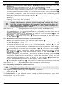
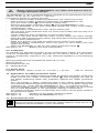
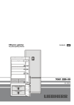
Bild 3:
Spannungsmessung mit AUTO SENSE
Funktion
Voltage measurement with AUTO SENSE
function
Fig. 3:
Mesure de tension avec fonction « AUTO
SENSE »
фигура 3: Измерване на напрежение с
функцията AUTO SENSE
Obr. 3:
Měření napětí s funkcí AUTO SENSE
Εικόνα 3: Μέτρηση της τάσης με την επιλογή
λειτουργίας AUTO SENSE
3. ábra: Feszültségmérés AUTO SENSE
funkcióban
Ill. 3:
Misurazione di tensione con funzione
AUTO SENSE
Fig. 3:
Spanningsmeting met AUTO SENSEfunctie
Rysunek 3: Pomiar napięcia z funkcją AUTO SENSE
Imaginea 3:Măsurarea tensiunii cu funcţia AUTO
SENSE
Bild 3:
Spänningsmätning med AUTO SENSEfunktion
Fig. 3:
0
100M
10M
100k
100kM
AUTO SENSE
10Gk
LOCK
V
COMP
COMPARE
PI
100Gk
V
DAR
KMΩ
GΩ
µmA
100200
500KMΩ
RECALL
PI/DAR
STORE
LOCK
PASS
TEST
MΩ L
eak
a
ge
Cu
50 V 100 V 250 V
500 V
1000 V
en
rr
Ω
t
V
OFF
TRUE RMS
V
Ω
> 660 V INSULATION
COM
CAT.IV
600 V
FUSED
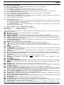
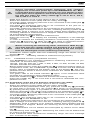
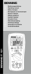
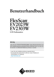
Bild 4:
Fig. 4:
0
100M
10M
100k
AUTO SENSE
100kM
10Gk
LOCK
V
COMP
COMPARE
PI
100Gk
V
DAR
KMΩ
GΩ
µmA
100200
500KMΩ
RECALL
PI/DAR
STORE
LOCK
PASS
TEST
MΩ L
eak
a
ge
Cu
50 V 100 V 250 V
500 V
1000 V
en
rr
Ω
t
V
OFF
TRUE RMS
V
Ω
> 660 V INSULATION
COM
CAT.IV
600 V
FUSED
Widerstands- und Niederohmmessung
Resistance and low-resistance
measurement
Fig. 4:
Mesure de résistance et de basse
impédance
фигура 4: Измерване на съпротивление и ниско
съпротивление
Obr. 4:
Měření odporu a nízkoohmové měření
Εικόνα 4: Μέτρηση ηλεκτρικής αντίστασης και
χαμηλής ωμικής αντίστασης
4. ábra: Ellenállás és kis értékű ellenállás mérés
Ill. 4:
Misurazione di resistenza e bassa
resistenza
Fig. 4:
Weerstands- en laagohmige meting
Rysunek 4:Pomiar rezystancji i niskiej rezystancji
Imaginea 4:Măsurarea rezistenţei şi a celei de mică
rezistenţă
Bild 4: Mätning av resistans och lågresistans
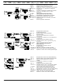
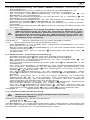
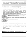
Bild 5:
Isolationswiderstandsmessung
(symbolisch)
Insulating resistance measurement
(symbolic)
Fig. 5:
Mesure de résistance d‘isolement
(symbolisée)
фигура 5: Измерване на изолационно
съпротивление (символично)
Obr. 5:
Měření izolačního odporu
Εικόνα 5: Μέτρηση ηλεκτρικής μονωτικής
αντίστασης (συμβολικά)
5. ábra: Szigetelési ellenállás mérés (szimbolikus
rajz)
Ill. 5:
Misurazione di resistenza d‘isolamento
(simbolico)
Fig. 5:
Meten van isolatieweerstand (symbolisch)
Rysunek 5:Pomiar rezystancji izolacji (symboliczny)
Imaginea 5:Măsurarea rezistenţei izolaţiei (simbolic)
Bild 5: Mätning av isoleringsresistans
(symboliskt)
Fig. 5:
0
100M
10M
100k
AUTO SENSE
10Gk
LOCK
V
COMP
100kM
COMPARE
PI
DAR
100Gk
V
KMΩ
GΩ
µmA
100200
500KMΩ
RECALL
PI/DAR
STORE
LOCK
PASS
TEST
MΩ L
eak
a
ge
Cu
50 V 100 V 250 V
500 V
1000 V
en
rr
Ω
t
V
OFF
TRUE RMS
V
Ω
> 660 V INSULATION
COM
FUSED
02/ 2011
CAT.IV
600 V
BENNING IT 101
,200kΩ,500kΩ,1MΩ,2MΩ,5MΩ,10MΩ,20MΩ,
100MΩ,200MΩ and 500MΩ.
measured value is greater than the selected compare
the green Pass indicator will be turned on.
DFHIS
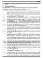
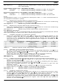
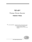
Bild 6:
Messung Polarisationsindex (PI)/
dielektrische Absorptionsrate (DAR)
Measuring the polarization index (PI) /
dielectric absorption rate (DAR)
Fig. 6:
Mesure de l‘indice de polarisation («PI»)/
du rapport d‘absorption diélectrique
(«DAR»)
фигура 6: Измерване на поляризационен индекс
(Pl)/ ниво на диелектрична абсорбция
(DAR)
Obr. 6:
Měření indexu polarizace (PI)/
dielektrické absorpce (DAR)
Εικόνα 6: Μέτρηση του δείκτη πόλωσης (PI)/ του
ρυθμού της διηλεκτρικής απορρόφησης
(DAR)
6. ábra: Polarizácios index (PI) és dielektromos
abszorpcióa arány (DAR) mérése
Ill. than
6: 2, Misurazione dell’indice di polarizzazione
e reading for DAR is bigger than 1.3 or PI is bigger
(PI)/ indice di assorbimento dielettrico
icate a Index)=R10-min/R1-min
good insulation quality.
zation
n the measured
resistance
is higher than the maximum (DAR)
lectric
Absorption
Rations)=R1-min/R30-sec
Fig.
6:
e, reading
the screen
will display
"Err"
symbol
value.
he
for DAR
is bigger
than
1.3 orfor
PIPI/DAR
is bigger
than
2,Meting polarisatie-index (PI)/ diëlektrische
absorptieratio (DAR)
dicate
a good
insulation
T
button
: Press
once to quality.
start/interrupt the PI /DAR
test. 6: Pomiar wskaźnika polaryzacji (PI) i
Rysunek
:enthe
insulation
resistance
measured
at
the
10
minute
the measured resistance is higher than the maximum
button : Press
once during the PI/DAR test to display theabsorbcji dielektrycznej (DAR)
ssing
TEST
ge, thethe
screen
willbutton.
display "Err" symbol for PI/DAR value.
Imaginea 6:Măsurarea indexului de polaritate (PI)/
left of the test.
the
insulation
measuredtheatPIthe
1 minute
ST
button
: Pressresistance
once to start/interrupt
/DAR
test. rata de absorbţie dielectrică (DAR)
ssing
the
TEST
button.
6: the
Mätning av polariseringsindex (PI) och
e button : Press once during the PI/DAR test to Bild
display
dielektrisk absorptionsratio (DAR)
: the insulation resistance measured at the 30 second
ring PI/DAR
Fig. 6:
e left of the test.
e
measured
ssing
the TESTvalues
button.after the PI test
R10-min/R1-min
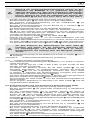
Bild 7:
Messergebnisse nach PI-Messung
Measuring results after PI measurement
Résultats de mesure suite à la mesure
«PI»
фигура 7: Измервателни резултати след Pl
измерване
Obr. 7:
Výsledky po měření PI
Εικόνα 7: Αποτελέσματα μέτρησης PI (δείκτης
πόλωσης)
7. ábra: PI mérés mérési eredmények
Ill. 7:
Risultati della misurazione di PI
Fig. 7:
Meetresultaten na PI-meting
Rysunek 7: Wyniki pomiarów po pomiarze PI
Imaginea 7: Rezultatele măsurătorilor după
măsurarea PI
Bild 7: Mätresultat efter PI-mätning
test
e measured values after the PI test Fig. 7:
Fig. 7:
=R10-min/R1-min 7
e measured values after the DAR
R=R1-min/R30-sec
e measured values after the DAR test
AR=R1-min/R30-sec
Bild 8:
Fig. 8:
Messergebnisse nach DAR-Messung
Measuring results after DAR
measurement
Fig. 8:
Résultats de mesure suite à la mesure
«DAR»
фигура 8: Измервателни резултати след DAR
измерване
Obr. 8:
Výsledky po měření DAR
Εικόνα 8: Αποτελέσματα μέτρησης DAR (ρυθμός
διηλεκτρικής απορρόφησης)
8. ábra: DAR mérés mérési eredmények
Ill. 8:
Risultati della misurazione di DAR
Fig. 8:
Meetresultaten na DAR-meting
Rysunek 8: Wyniki pomiarów po pomiarze DAR
Imaginea 8: Rezultatul măsurătorilor după măsurarea
DAR
Bild 8: Mätresultat efter DAR-mätning
8
8
02/ 2011
BENNING IT 101
Using the Recall function
Press the Store/Recall button ≧2 sec to enter/exit the RECALL
mode.
If the memory is empty, the meter will display the “nOnE ”
symbol.
DFHIS
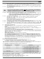
Bild 9:
Gespeicherte Messwerte aufrufen
Calling stored measured values
Fig. 9:
Appel des valeurs mesurées mémorisées
фигура 9: Извикване на съхранени измерени
стойности
Obr. 9:
Vyvolání uložených naměřených hodnot
Εικόνα 9: Ανάκληση αποθηκευμένων τιμών
μέτρησης
9. ábra: Tárolt mérési érték előhívásal
Ill. 9:
Visualizzazione dei valori salvati
Fig. 9:
Opgeslagen meetwaarden opvragen
Rysunek 9: Przywołanie zapisanych wartości
Imaginea 9: Apelarea valorilor măsurate şi stocate
(memorate)
Bild 9: Hämta sparade mätvärden
Search the stored value under RECALL mode
Fig. 9:
9
ead the stored value of insulation test under
ECALL mode
Bild 10:
Gespeicherte Werte der
Isolationsmessung
Stored values of the insulation
measurement
Fig. 10: Valeurs mémorisées de la mesure
d‘isolement
фигура 10:Съхранени стойности от изолационно
измерване
Obr. 10: Uložené hodnoty měření izolace
Εικόνα 10: Αποθηκευμένες τιμές της μέτρησης της
μόνωσης
10. ábra: Tárolt szigetelésmérési értékek
Ill. 10:
Valori salvati di misurazione
dell‘isolamento
Fig. 10: Opgeslagen waarden van de
isolatiemeting
Rysunek 10:Zapisane wartości pomiaru izolacji
Imaginea 10: Valori memorate ale măsurării izolaţiei
Bild 10: Sparade värden från isoleringsmätningen
Read the stored value of insulation test under
Fig. 10:
RECALL mode
ead
valueofofDAR
DAR
test
under
Readthe
thestored
stored value
test
under
ECALL
RECALLmode
mode
Press
thePI/DAR
PI/DAR button
to to
choose
the DAR
ess
the
button≧≧2 2sec
sec
choose
the DAR
function,and
andPress
Press the
button
≧ 2≧
sec
enter
nction,
theStore/Recall
Store/Recall
button
2 to
sec
to enter
RECALLmode.
mode.
ethe
RECALL
Bild 11: Gespeicherte Werte der DAR-Messung
Fig. 11:
Stored values of the DAR measurement
Fig. 11: Valeurs mémorisées de la mesure
«DAR»
фигура 11: Съхранени стойности от DAR
измерване
Obr. 11: Uložené hodnoty měření DAR
Εικόνα 11: Αποθηκευμένες τιμές της μέτρησης DAR
(ρυθμός διηλεκτρικής απορρόφησης)
11. ábra: Tárolt DAR-mérési érték előhívása
Ill. 11:
Valori salvati di misurazione del DAR
Fig. 11:
Opgeslagen waarden van de DAR-meting
Rysunek 11:Zapisanych wartości pomiarów DAR
Imaginea 11: Valori stocate ale măsurării-DAR
Bild 11: Sparade värden från DAR-mätningen
10
10
02/ 2011
BENNING IT 101
Read the stored value of PI test under
RECALL mode
DFHIS
Press the PI/DAR button ≧2 sec to choose the PI function,
and Press the Store/Recall button ≧2 sec to enter the
RECALL mode.
Bild 12: Gespeicherte Werte der PI-Messung
Fig. 12: Stored values of the PI measurement
Fig. 12: Valeurs mémorisées de la mesure «PI»
фигура 12:Съхранени стойности от Pl измерване
Obr. 12: Uložené hodnoty měření PI
Εικόνα 12: Αποθηκευμένες τιμές της μέτρησης PI
(δείκτης πόλωσης)
12. ábra: Tárolt PI-mérési értékek előhívása
Ill. 12:
Valori salvati di misurazione del PI
Fig. 12: Opgeslagen waarden van de PI-meting
Rysunek 12:Zapisanych wartości pomiarów PI
Imaginea 12: Valori stocate ale măsurării-PI.
Bild 12: Sparade värden från PI-mätningen
Auto Power Off (Battery Saver)
0
100k
100M
10M
AUTO SENSE
100kM
LOCK
10Gk
100Gk
V
KMΩ
Bild 13: Batterie- und Sicherungswechsel
Fig. 13: Battery and fuse replacement
Fig. 13: Remplacement des piles et du fusible
COMPARE
V P I DAR 100200
500KMΩ
фигура 13:Смяна на батериите и предпазителя
Obr. 13: Výměna baterie a pojistky
RECALL
PI/DAR
Εικόνα 13: Αλλαγή μπαταριών και ηλεκτρικής
COMProtor STORE
LOCK
Restore power by switching
or pressing
any button.
ασφάλειας
PASS
Auto Backlight
13. ábra: Telep és biztosító csere
TEST
The backlight is automatically turned on at dark environment.
MΩ L
Ill.
13:
Sostituzione
di batterie e fusibile
eak
ag
eC
u
BUZZER
50 V 100 V 250 V
Fig. 13: Batterij en zekering vervangen
Ω
500 V
The Meter beeps once for every valid key-press,
and beeps Rysunek 13:Wymiana baterii i bezpiecznika
1000 V
twice for every invalidV key-press.
Imaginea 13: Schimbarea bateriei şi al siguranţelor
OFF
Bild 13: Batteri- /säkringsbyte
GΩ
µmA
en
rr
t
11
TRUE RMS
V
Ω
> 660 V INSULATION
COM
FUSED
CAT.IV
600 V
Bild 14:
Fig. 14: Fig. 14:
Aufwicklung der Sicherheitsmessleitung
Winding up the safety measuring leads
Enroulement du câble de mesure de
sécurité
фигура 14:Закрепване на сондите
Obr. 14: Navinutí bezpečnostních měřících kabelů
Εικόνα 14: Περιτύλιξη του μετρητικoύ αγωγού
ασφαλείας
14. ábra: A mérővezetékek felcsavarása
Ill. 14:
Avvolgimento dei cavetti di sicurezza
Fig. 14: Wikkelen van de veilighh
eidsmeetsnoeren
Rysunek 14:Zwijanie bezpiecznych przewodów
pomiarowych
Imaginea 14: Înfăşurarea firelor de măsurare pe rama
din cauciuc
Bild 14: Fastlindning av säkerhetsmätkablarna
Bild 15: Aufstellung des BENNING IT 101
Fig. 15: Erecting the BENNING IT 101
Fig. 15: Installation du BENNING IT 101
фигура 15:Повдигане на BENNING IT 101
Obr. 15: Postavení přístroje BENNING IT 101
Εικόνα 15: Τοποθέτηση του BENNING IT 101
15. ábra: A BENNING IT 101 felállítása
Ill. 15:
Posizionamento del BENNING IT 101
Fig. 15: Opstelling van de BENNING IT 101
Rysunek 15:Zamontowanie przyrządu BENNING IT 101
Imaginea 15: Poziţionarea pe verticală a aparatului
BENNING IT 101
Bild 15: Uppställning av BENNING IT 101
02/ 2011
BENNING IT 101
D
Bedienungsanleitung
BENNING IT 101
Isolations- und Widerstandsmessgerät zur
-Isolationswiderstandsmessung
-Niederohmmessung
-Widerstandsmessung
-Gleichspannungsmessung
-Wechselspannungsmessung
- Messung/ Berechnung des Polarisationsindex (PI)
- Messung/ Berechnung der dielektrischen Absorptionsrate (DAR)
Inhaltsverzeichnis
1.Benutzerhinweise
2.Sicherheitshinweise
3. Lieferumfang
4.Gerätebeschreibung
5. Allgemeine Angaben
6.Umgebungsbedingungen
7. Elektrische Angaben
8. Messen mit dem BENNING IT 101
9.Instandhaltung
10. Anwendung des Gummi-Schutzrahmens
11.Umweltschutz
1.Benutzerhinweise
Diese Bedienungsanleitung richtet sich an:
-
-
Elektrofachkräfte (EF), befähigte Personen und
elektrotechnisch unterwiesene Personen (EuP)
Das BENNING IT 101 ist zur Messung in trockener Umgebung vorgesehen. Es
darf nicht in Stromkreisen mit einer höheren Nennspannung als 600 V DC/ AC
eingesetzt werden (näheres hierzu im Abschnitt 6. „Umgebungsbedingungen“).
In der Bedienungsanleitung und auf dem BENNING IT 101 werden folgende
Symbole verwendet:
Warnung vor elektrischer Gefahr!
Steht vor Hinweisen, die beachtet werden müssen, um Gefahren
für Menschen zu vermeiden.
Achtung Dokumentation beachten!
Das Symbol gibt an, dass die Hinweise in der Bedienungsanleitung
zu beachten sind, um Gefahren zu vermeiden.
Dieses Symbol auf dem BENNING IT 101 bedeutet, dass das
BENNING IT 101 schutzisoliert (Schutzklasse II) ausgeführt ist.
Dieses Warnsymbol weist darauf hin, dass das BENNING IT 101
nicht in Verteilersystemen mit Spannungen höher als 600 V
angewendet werden darf.
Dieses Symbol auf dem BENNING IT 101 bedeutet, dass das
BENNING IT 101 konform zu den EU-Richtlinien ist.
Dieses Symbol erscheint in der Anzeige für eine entladene
Batterie.
Dieses Symbol auf dem BENNING IT 101 weist auf die
eingebauten Sicherungen hin.
(DC) Gleich- oder (AC) Wechselstrom
Erde (Spannung gegen Erde).
Bitte führen Sie das Gerät am Ende seiner Lebensdauer den zur
Verfügung stehenden Rückgabe- und Sammelsystemen zu.
02/ 2011
BENNING IT 101
1
D
2.Sicherheitshinweise
Das Gerät ist gemäß
DIN VDE 0411 Teil 1/ EN 61010 Teil 1
DIN VDE 0413 Teil 1, 2 und 4/ EN 61557 Teil 1, 2 und 4
gebaut und geprüft und hat das Werk in einem sicherheitstechnisch einwand-freien Zustand verlassen. Um diesen Zustand zu erhalten und einen
gefahrlosen Betrieb sicherzustellen, muss der Anwender die Hinweise und
Warnvermerke beachten, die in dieser Anleitung enthalten sind. Fehlverhalten
und Nichtbeachtung der Warnungen kann zu schwerwiegenden Verletzungen
oder zum Tode führen.
Das Gerät darf in Stromkreisen bis zur Überspannungskategorie
IV mit max. 600 V Leiter gegen Erde benutzt werden.
Hierzu sind geeignete Messleitungen zu verwenden.
Bei Messungen innerhalb der Messkategorie III oder der
Messkategorie IV darf das hervorstehende leitfähige Teil einer
Kontaktspitze der Messleitung nicht länger als 4 mm sein.
Vor Messungen innerhalb der Messkategorie III und der
Messkategorie IV müssen, die dem Set beigestellten, mit CAT
III und CAT IV gekennzeichneten, Aufsteckkappen auf die
Kontaktspitzen aufgesteckt werden. Diese Maßnahme dient
dem Benutzerschutz.
Beachten Sie, dass Arbeiten an spannungsführenden Teilen und
Anlagen grundsätzlich gefährlich sind. Bereits Spannungen ab
30 V AC und 60 V DC können für den Menschen lebensgefährlich
sein. Ab einer Eingangsspannung von 30 V AC/ DC erscheint im
Display des BENNING IT 101 das Warnsymbol R, welches
vor dem Anliegen einer gefährlichen Spannung warnt. Zusätzlich
leuchtet die rote Hochspannungs-Kontrollanzeige 9 auf.
Vor jeder Inbetriebnahme überprüfen Sie das Gerät und die
Leitungen auf Beschädigungen.
Achtung! Während der Isolationswiderstandsmessung können
am BENNING IT 101 gefährliche Spannungen auftreten.
Ist anzunehmen, dass ein gefahrloser Betrieb nicht mehr möglich ist, ist das
Gerät außer Betrieb zu setzen und gegen unbeabsichtigten Betrieb zu sichern.
Es ist anzunehmen, dass ein gefahrloser Betrieb nicht mehr möglich ist,
- wenn das Gerät oder die Messleitungen sichtbare Beschädigungen aufweisen,
- wenn das Gerät nicht mehr arbeitet,
- nach längerer Lagerung unter ungünstigen Verhältnissen,
- nach schweren Transportbeanspruchungen,
- wenn das Gerät oder die Messleitungen feucht sind.
Um eine Gefährdung auszuschließen
-
berühren Sie die Messleitungen nicht an den blanken
Messspitzen,
-
dekontaktieren Sie bei Spannungsmessung zuerst die
schaltbare Prüfspitze vom BENNING IT 101
-
stecken Sie die Messleitungen in die entsprechend
gekennzeichneten Messbuchsen am BENNING
IT
101
siehe Bild 1: Gerätefront
-beim Trennen des Messkreises entfernen Sie immer zuerst
die spannungsführende Messleitung (Phase) und dann die
Null Messleitung von der Messstelle
-verwenden Sie das BENNING IT 101 nicht in der Umgebung
von explosiven Gasen oder Stäuben.
Wartung:
Das Gerät nicht öffnen, sie enthält keine durch den Benutzer
wartbaren Komponenten. Reparatur und Service kann nur
durch qualifiziertes Personal erfolgen.
Reinigung:
Das Gehäuse regelmäßig mit einem Tuch und Reinigungsmittel
trocken abwischen. Kein Poliermittel oder Lösungsmittel
verwenden.
02/ 2011
BENNING IT 101
2
D
3. Lieferumfang
Zum Lieferumfang des BENNING IT 101 gehören:
3.1 ein Stück BENNING IT 101
3.2 zwei Stück Sicherheitsmessleitungen, rot/ schwarz, (L = 1,2 m)
3.3 zwei Stück Sicherheitskrokodilklemmen, rot/ schwarz, 4 mm Stecktechnik
3.4 ein Stück schaltbare Prüfspitze mit integrierter TEST-Taste (T.Nr. 044115)
3.5 ein Stück Gummi-Schutzrahmen
3.6 ein Stück Magnetaufhänger mit Adapter und Riemen (T.Nr. 044120)
3.7 ein Stück Kompakt-Schutztasche
3.8vier Stück 1,5 V Mignon-Batterien/ Typ AA, IEC LR6 und eine Sicherung
(zur Erstbestückung im Gerät eingebaut)
3.9 eine Bedienungsanleitung
Hinweis auf Verschleißteile:
- Das BENNING IT 101 enthält eine Sicherung zum Überlastschutz:
Ein Stück Sicherung Nennstrom 315 mA (1000 V), 10 kA, FF, D = 6,3 mm,
L = 32 mm (T.Nr. 757213)
- Das BENNING IT 101 wird durch vier eingebaute 1,5 V Mignon-Batterien/
Typ AA, IEC LR6 gespeist.
4.Gerätebeschreibung
siehe Bild 1:
Gerätefrontseite
siehe Bild 2:
Digitalanzeige
Die in Bild 1 und 2 angegebenen Anzeige- und Bedienelemente werden wie
folgt bezeichnet:
1 Sensor, der automatischen Hintergrundbeleuchtung
2 Digitalanzeige
AUTO SENSE, für automatische Erkennung der Gleich- (DC) und Wechsel
spannung (AC),
B Digitalanzeige, für den Messwert und analoge Bargraphanzeige,
C TEST, erscheint bei Aktivierung der Messung des Isolationswiderstandes
und niederohmigen Widerstands
D LOCK (Feststellung), ermöglicht eine fortlaufende (kontinuierliche)
Messung von Isolationswiderstand und niederohmigen Widerstand,
E APO, erscheint bei automatischer Abschaltung (Auto Power Off),
F LPF, erscheint bei aktiviertem Tiefpassfilter (Low Pass Filter),
G AC/ DC, erscheint bei gemessener Gleich- (DC) und Wechselspannung (AC),
H
, erscheint bei Kompensation (Nullabgleich) der Messleitungen,
I Bereichsanzeigen,
J COMPARE, erscheint bei der Vergleichsfunktion in der Iso
la
tions
wi
der
standsmessung,
K DAR, erscheint bei aktivierter Messung der dielektrischen Absorptionsrate
L PI, erscheint bei aktivierter Messung des Polarisationsindex
M Prüfspannungsanzeige, erscheint bei der Messung des Isolationswider
stands,
N Uhr, Messzeit der PI-/ DAR-Messung
O Batterieanzeige „
“, erscheint bei entladener Batterie,
P Bereichsüberschreitung,
Q Polaritätsanzeige,
R (Hochspannungs-Kontrollanzeige), erscheint vor dem Anliegen einer
gefährlichen Spannung,
S MEM, erscheint bei aktiviertem internen Messwertspeicher,
3 Taste (blau), Umschalttaste für die Zweitfunktion
4 COMP-Taste, aktiviert die Vergleichsfunktion in der Isolationswiderstands
messung,
5 STORE/ RECALL-Taste, Speicherung und Aufruf von Messwerten,
6 LOCK (Feststellung)/ PI/ DAR-Taste, für die fortlaufende Messung von
Isolationswiderstand und niederohmigem Widerstand, sowie für die Ermitt
lung des Polarisationsindex und der dielektrischen Absorptionsrate
7 Grüne LED (PASS), Kontrollanzeige leuchtet auf, wenn der gemessene Wert den Vergleichswert (Widerstandswert) im COMP-Modus überschreitet.
8 TEST-Taste, aktiviert die Messung des Isolationswiderstandes und niederohmigen Widerstandes,
9 Rote LED (Hochspannungs-Kontrollanzeige), leuchtet beim Anliegen
einer gefährlichen Spannung auf,
J Drehschalter, für die Wahl der Messfunktionen,
K Ω-Buchse, für Widerstands- und Niederohmmessungen,
L Buchse (positive), für Spannungs- und Isolationsmessungen,
Polarisationsindex (PI), dielektrische Absorptionsrate (DAR),
M COM-Buchse, gemeinsame Buchse für Spannungs-, Widerstands-,
Niederohm-, Isolationsmessungen, Polarisationsindex (PI), dielektrische
02/ 2011
BENNING IT 101
3
D
Absorptionsrate (DAR)
N Gummi-Schutzrahmen.
5. Allgemeine Angaben
Das BENNING IT 101 führt elektrische Messungen zum Isolationswiderstand aus.
Das BENNING IT 101 unterstützt elektrische Sicherheitsprüfungen nach DIN
VDE 0100, IEC 60364, VDE 0701-0702, BGV A3, ÖVE/ ÖNORM E8701 und
NEN 3140.
Voreingestellte Grenzwerte erleichtern die Bewertung.
5.1 Allgemeine Angaben zum Isolationswiderstandsmessgerät
5.1.1 Die Digitalanzeige B für den Messwert B ist als 3½-stellige Flüssig
kristallanzeige mit 15 mm Schrifthöhe und Dezimalpunkt ausgeführt.
Der größte Anzeigewert ist 4000.
5.1.2 Die Bargraphanzeige B besteht aus 49 Segmenten und zeigt den
Widerstand in einer logarithmischen Skala an.
5.1.3 Die Polaritätsanzeige Q wirkt automatisch. Es wird nur eine Polung
entgegen der Buchsendefinition mit ,,-" angezeigt.
5.1.4 Die Digitalanzeige für die Prüfspannung M ist als 3½-stellige Flüssig
kristallanzeige mit 7 mm Schrifthöhe ausgeführt. Der größte Anzeige
wert ist 1999.
5.1.5 Die Bereichsüberschreitung der Digitalanzeige wird durch ein „>"
Symbol P angezeigt.
5.1.6 Das BENNING IT 101 besitzt eine automatische Messbereichswahl.
5.1.7 Das BENNING IT 101 besitzt eine automatische Hintergrundbeleuchtung
(Auto Backlight). Im Kopfbereich befindet sich der Helligkeitssensor 1.
Sinkt die Umgebungsbeleuchtung, schaltet sich die Hinter
grund
be
leuchtung automatisch ein.
5.1.8 Einmal ertönt ein akustisches Signal (Summer) bei jedem gültigen
Tastendruck und zweimal bei einem ungültigen Tastendruck.
5.1.9 Die Taste (blau) 3 wählt die Zweitfunktion der Drehschalterstellung an.
In der Schalterstellung V wird der Tiefpassfilter (LPF) aktiviert. In der
Stellung Ω wird eine Kompensation (Nullabgleich) der Messleitungen
ermöglicht ( ). In den Schalterstellungen 50 V/ 100 V/ 250 V/ 500 V
und 1000 V wird der Isolationswiderstand oder Leckstrom angezeigt.
5.1.10 Die Taste COMP 4 aktiviert die Vergleichsfunktion in der Isolationswi
derstandsmessung.
5.1.11 Die Taste STORE/ RECALL 5 dient dem Speichern und Aufrufen von
Messwerten.
5.1.12 Die Taste LOCK (Feststellung) 6 ermöglicht fortlaufende Messungen
von Iso
lationswiderstand und niederohmigem Widerstand, ohne ein
erneutes Betätigen bzw. Festhalten der TEST-Taste 8. Für eine fortlaufende Messung betätigen Sie die LOCK-Taste, betätigen Sie dann
die TEST-Taste. Im Display 2 erscheint das „LOCK“-Symbol D. Bei
der Messung des Isolationswiderstandes bewirkt die TEST-Taste ein
fortlaufendes Anlegen der Prüfspannung an die Messstelle. Bei der
Niederohmmessung bewirkt die TEST-Taste ein fortlaufendes Anlegen
des Prüfstromes an die Messstelle. Die Feststellung kann durch
Betätigen der LOCK-Taste oder TEST-Taste beendet werden.
Im Modus der Feststellung (LOCK-Taste) erkennt das
BENNING IT 101 keine Fremdspannung an dem Eingang des
Gerätes. Stellen Sie sicher, dass die Messstelle spannungsfrei
ist bevor Sie die Feststellung aktivieren, da sonst die Sicherung
durchbrennen könnte.
Die Taste LOCK aktiviert die Messung der dielektrischen Absorptionsrate
(DAR) K und des Polarisationsindex (PI) L.
5.1.13Die grüne LED 7 (PASS-Kontrollanzeige) leuchtet in der
Vergleichsfunktion (Taste COMP 4), wenn der gemessene Wert den
Vergleichswert (Widerstandswert) überschreitet.
5.1.14 Die Taste TEST 8 aktiviert die Messung des Isolationswiderstandes
und des niederohmigen Widerstandes.
5.1.15 Die rote LED 9 ( Hochspannungs-Kontrollanzeige), leuchtet
beim Anliegen einer gefährlichen Spannung auf. Im Display 2 des
BENNING IT 101 erscheint das Warnsymbol R.
5.1.16 Das BENNING IT 101 wird durch den Drehschalter J ein- oder ausgeschaltet. Ausstellung „OFF“.
5.1.17 Das BENNING IT 101 schaltet sich nach ca. 20 Min. selbsttätig aus. Im
Modus der Feststellung („LOCK“) D (fortlaufende Messung) erfolgt die
Abschaltung nach ca. 30 Min. Eine Wiedereinschaltung erfolgt automatisch durch Tastenbetätigung, Drehung des Messbereichsdrehschalters
oder durch Anlegen einer Spannung ab 30 V AC/ DC an den Eingang
des Gerätes.
02/ 2011
BENNING IT 101
4
D
5.1.18 Temperaturkoeffizient des Messwertes: 0,15 x (angegebene Messge
nauigkeit)/ °C < 18 °C oder > 28 °C, bezogen auf den Wert bei der
Referenztemperatur von 23 °C.
5.1.19 Das BENNING IT 101 wird durch vier Mignon-Batterien 1,5 V gespeist
(IEC LR6/ AA).
Sobald das Batteriesymbol
O erscheint, tauschen Sie umgehend die Batterien gegen neue Batterien aus, um eine Gefährdung
durch Fehlmessungen für den Menschen zu vermeiden.
5.1.20 Bei voller Batteriekapazität ermöglicht das BENNING IT 101 eine
Anzahl von ca.
-2600 Niederohmmessungen (gemäß EN 61557-4) [1 Ω, bei 5 Sek.
Messdauer] oder
- 1100 Messungen des Isolationswiderstandes (1000 V) (gemäß EN
61557-2) [1 MΩ, bei 1000 V und 5 Sek. Messdauer]
5.1.21Geräteabmessungen:
(L x B x H) = 200 x 85 x 40 mm ohne Gummi-Schutzrahmen
(L x B x H) = 207 x 95 x 52 mm mit Gummi-Schutzrahmen
Gerätegewicht:
470 g ohne Gummi-Schutzrahmen
630 g mit Gummi-Schutzrahmen
5.1.22 Die mitgelieferten Sicherheitsmessleitungen sind ausdrücklich für die
Nennspannung und dem Nennstrom des BENNING IT 101 geeignet.
5.1.23 Das BENNING IT 101 wird durch einen Gummi-Schutzrahmen N vor
mechanischer Beschädigung geschützt. Der Gummi-Schutzrahmen
ermöglicht es, das BENNING IT 101 während der Messungen aufzustellen oder aufzuhängen.
6.Umgebungsbedingungen
- Das BENNING IT 101 ist für Messungen in trockener Umgebung vorgesehen
- Barometrische Höhe bei Messungen: maximal 2000 m
- Überspannungskategorie/ Aufstellungskategorie: IEC 61010-1 → 600 V
Kategorie IV
- Verschmutzungsgrad: 2
- Schutzart: IP 40 (DIN VDE 0470-1, IEC/ EN 60529)
4 - erste Kennziffer: Schutz gegen kornförmige Fremdkörper
0 - zweite Kennziffer: Kein Wasserschutz,
- EMC: EN 61326-1
- Arbeitstemperatur und relative Luftfeuchte:
Bei Arbeitstemperatur von 0 °C bis 30 °C: relative Luftfeuchte kleiner 80 %,
Bei Arbeitstemperatur von 31 °C bis 40 °C: relative Luftfeuchte kleiner 75 %,
Bei Arbeitstemperatur von 41 °C bis 50 °C: relative Luftfeuchte kleiner 45 %,
- Lagerungstemperatur: Das BENNING IT 101 kann bei Temperaturen von
- 20 °C bis + 60 °C (Luftfeuchte 0 bis 80 %) gelagert werden. Dabei sind
die Batterien aus dem Gerät herauszunehmen.
7. Elektrische Angaben
Bemerkung: Die Messgenauigkeit wird angegeben als Summe aus
- einem relativen Anteil des Messwertes und
- einer Anzahl von Digit (d.h. Zahlenschritte der letzten Stelle).
Diese Messgenauigkeit gilt bei Temperaturen von 18 °C bis 28 °C und einer
relativen Luftfeuchtigkeit kleiner 80 %.
7.1 Spannungsbereiche (Schalterstellung V)
Messbereich
Auflösung
Messgenauigkeit
600 V DC
0,1 V
± (1,0 % des Messwertes + 5 Digit)
600 V AC
0,1 V
± (1,5 % des Messwertes + 5 Digit)
im Frequenzbereich 50 Hz - 60 Hz
± (2,0 % des Messwertes + 5 Digit)
im Frequenzbereich 61 Hz - 500 Hz
600 V AC
mit Tiefpassfilter (LPF)
0,1 V
± (1,5 % des Messwertes + 5 Digit)
im Frequenzbereich 50 Hz - 60 Hz
± (5,0 % des Messwertes + 5 Digit)
im Frequenzbereich 61 Hz - 400 Hz
Optische Warnung bei einer gefährlichen Spannung ab 30 V AC/ DC ()
Minimale Messspannung: 0,6 V (AC)
Überspannungsschutz: 600 V RMS oder DC
Grenzfrequenz des Tiefpassfilters (LPF): 1 kHz
Eingangsimpedanz: 3 MΩ/ weniger als 100 pF
02/ 2011
BENNING IT 101
5
D
AC Umrechnung:
AC Umrechnung ist kapazitiv gekoppelt (AC-gekoppelt), TRUE RMS Verhalten,
kalibriert auf ein Sinus-Signal. Bei nichtsinusförmigen Kurvenformen wird der
Anzeigewert ungenauer. So ergibt sich für folgende Crest-Faktoren ein zusätzlicher Fehler:
Crest Faktor von 1,4 bis 2,0 zusätzlicher Fehler + 1,0 %
Crest Faktor von 2,0 bis 2,5 zusätzlicher Fehler + 2,5 %
Crest Faktor von 2,5 bis 3,0 zusätzlicher Fehler + 4,0 %
7.2Isolationswiderstandsbereiche
(Schalterstellung MΩ, 50 V/ 100 V/ 250 V/ 500 V/ 1000 V)
Messbereich
Auflösung
Messgenauigkeit
4 MΩ
0,001 MΩ
± (1,5 % des Messwertes + 5 Digit)
40 MΩ
0,01 MΩ
± (1,5 % des Messwertes + 5 Digit)
400 MΩ
0,1 MΩ
± (3,0 % des Messwertes + 5 Digit)
4000 MΩ
1 MΩ
± (3,0 % des Messwertes + 5 Digit)
4,1 GΩ ... 20 GΩ
0,1 GΩ
± (10 % des Messwertes + 3 Digit)
Minimaler/ maximaler Widerstand in Abhängigkeit der Prüfspannung:
Prüfspannung
Minimaler Widerstand
(bei 1 mA)
50 V
50 kΩ
50 MΩ
100 V
100 kΩ
100 MΩ
250 V
250 kΩ
250 MΩ
500 V
500 kΩ
500 MΩ
1000 V
1 MΩ
20 GΩ
Maximaler Widerstand
Genauigkeit Prüfspannung: - 0 %, + 20 %
Kurzschlussstrom: 1 mA (nominal)
Automatische Entladefunktion: Entladezeit < 1 Sek. für C < 1 µF
Maximale kapazitive Last: funktionsbereit bis zu 1 µF Last
Detektion eines angeschlossenen Stromkreises: wenn > 30 V AC/ DC, dann
7.3 Widerstandsbereiche (Niederohmbereich) (Schalterstellung Ω)
Messbereich
Auflösung
Messgenauigkeit
40 Ω
0,01 Ω
± (1,5 % des Messwertes + 5 Digit)*
400 Ω
0,1 Ω
± (1,5 % des Messwertes + 3 Digit)
4000 Ω
1Ω
± (1,5 % des Messwertes + 3 Digit)
40 kΩ
0,01 kΩ
± (1,5 % des Messwertes + 3 Digit)
* < 1 Ω zusätzlich 3 Digit
Prüfspannung: > 4 V und 8 V
Kurzschlussstrom: > 200 mA
Detektion eines angeschlossenen Stromkreises: wenn > 2 V AC/ DC, dann
8. Messen mit dem BENNING IT 101
8.1 Vorbereiten der Messung
Benutzen und lagern Sie das BENNING IT 101 nur bei den angegebenen
Lager- und Arbeitstemperaturen, vermeiden sie dauernde Sonneneinstrahlung.
- Angaben von Nennspannungen und Nennstrom auf den Sicherheitsmessleitungen überprüfen. Die zum Lieferumfang gehörenden Sicherheitsmessleitungen entsprechen in Nennspannung und Nennstrom dem
BENNING IT 101.
- Isolation der Sicherheitsmessleitungen überprüfen. Wenn die Isolation
beschädigt ist, sind die Sicherheitsmessleitungen sofort auszusondern.
- Sicherheitsmessleitungen auf Durchgang prüfen. Wenn der Leiter in der
Sicherheitsmessleitung unterbrochen ist, sind die Sicherheitsmessleitungen
sofort auszusondern.
- Bevor am Drehschalter J eine andere Funktion gewählt wird, müssen die
Sicherheitsmessleitungen von der Messstelle getrennt werden.
- Starke Störquellen in der Nähe des BENNING IT 101 können zu instabiler
Anzeige und zu Messfehlern führen.
02/ 2011
BENNING IT 101
6
D
8.2 Spannungsmessung mit AUTO SENSE Funktion (automatische AC/
DC-Erkennung)
- Dekontaktieren Sie die schaltbare Prüfspitze vom BENNING IT 101.
- Mit dem Drehschalter J die gewünschte Funktion (V) wählen.
- Die schwarze Sicherheitsmessleitung mit der COM-Buchse M am
BENNING IT 101 kontaktieren.
- Die rote Sicherheitsmessleitung mit der Buchse für V, Insulation L am
BENNING IT 101 kontaktieren.
- Die Sicherheitsmessleitungen mit der Messstelle kontaktieren und den
Messwert im Display 2 am BENNING IT 101 ablesen.
- Spannungen größer 660 V AC/ DC werden im Display mit „>660 V AC/DC“
angezeigt.
- Ein blinkendes Warnsymbol R erscheint im Display bei Spannungen ab
30 V AC/ DC.
Das BENNING IT 101 zeigt entweder eine DC (Gleich) oder AC
(Wechselspannung) an. Falls die gemessene Spannung einen
DC- und einen AC-Anteil aufweist, wird immer nur die größere
Komponente angezeigt. Bei AC (Wechselspannung) wird der
Messwert durch eine Mittelwertgleichrichtung gewonnen und
als Effektivwert angezeigt.
siehe Bild 3:
Spannungsmessung mit AUTO SENSE Funktion
8.2.1 Spannungsmessung mit Tiefpassfilter (LPF)
- Das BENNING IT 101 besitzt einen integrierten Tiefpassfilter, mit einer
Grenzfrequenz von 1 kHz.
- Mit der Taste (blau) 3 am BENNING IT 101 wird der Tiefpassfilter aktiviert
(Taste einmal drücken).
- Ist der Filter aktiv, wird im Display 2 gleichzeitig das Symbol „LPF“ F
eingeblendet.
8.3 Widerstands- und Niederohmmessung
- Schalten Sie den Schaltkreis bzw. den Prüfling spannungsfrei.
- Mit dem Drehschalter J die gewünschte Funktion (Ω) wählen.
- Die schwarze Sicherheitsmessleitung mit der COM-Buchse M am
BENNING IT 101 kontaktieren.
- Die rote Sicherheitsmessleitung mit der Ω-Buchse K am BENNING IT 101
kontaktieren.
- Um eine Kompensation (Nullabgleich) des Messleitungswiderstandes
durchzuführen, kontaktieren Sie die Messleitungen (kurzschließen) und
drücken Sie die blaue Taste 3. Der Nullabgleich ist erfolgt, sobald im
Display 2 „ “ H erscheint.
- Die Sicherheitsmessleitungen mit der Messstelle kontaktieren, Taste
TEST 8 betätigen und den Messwert im Display 2 am BENNING IT 101
ablesen.
- Bei einer Spannung ab 2 V AC/ DC warnt zusätzlich ein blinkendes
Warnsymbol R vor dem Anliegen einer Fremdspannung und die
Widerstandsmessung wird abgebrochen. Schalten Sie den Schaltkreis
spannungsfrei und wiederholen Sie die Messung.
- Der Widerstandswert wird über das Display 2 angezeigt. Widerstände
größer 40 kΩ werden im Display mit „>40kΩ“ angezeigt.
- Um den Widerstandswert kontinuierlich zu messen, drücken Sie die
Taste LOCK 6 und dann die Taste TEST 8. Der Wert wird kontinuierlich
gemessen bis die Taste TEST 8 oder LOCK 6 erneut gedrückt wird.
siehe Bild 4: Widerstands- und Niederohmmessung
8.4Isolationswiderstandsmessung
Maximale Spannung gegen Erdpotential beachten!
Elektrische Gefahr!
Die höchste Spannung, die an den Buchsen,
-COM-Buchse M
- Buchse für V, Insulation L
des BENNING IT 101 gegenüber Erde liegen darf, beträgt 600 V. Vermeiden Sie
bei den Messungen Lichtbögen längerer Zeitdauer zwischen den Prüfspitzen/
Messstellen, diese können zu Gerätestörungen führen.
02/ 2011
BENNING IT 101
7
D
Während der Isolationswiderstandsmessung können an den
Prüfspitzen des BENNING IT 101 gefährliche Spannungen
auftreten. Beachten Sie, dass diese gefährlichen Spannungen
ebenfalls an blanken Metallteilen des Schaltkreises auftreten
können. Berühren Sie nicht die Prüfspitzen bei Stellung des
Drehschalters J auf Pos. 50 V, 100 V, 250 V, 500 V oder 1000 V.
- Schalten Sie den Schaltkreis bzw. den Prüfling spannungsfrei.
- Mit dem Drehschalter J die gewünschte Funktion (MΩ) wählen.
- Die schwarze Sicherheitsmessleitung mit der COM-Buchse M am
BENNING IT 101 kontaktieren.
- Die rote Sicherheitsmessleitung mit der Buchse für V, Insulation L am
BENNING IT 101 kontaktieren.
- Die Sicherheitsmessleitungen mit der Messstelle kontaktieren.
- Bei einer Spannung ab 30 V AC/ DC warnt ein blinkendes Warn
symbol
R vor dem Anliegen einer Fremdspannung und die Isolationswider
standsmessung wird abgebrochen. Schalten Sie den Schaltkreis span
nungsfrei und wiederholen Sie die Messung.
- Zum Start der Messung betätigen Sie die Taste TEST 8.
- Drücken Sie die blaue Taste 3, um den Isolationswiderstand oder den
Leckstrom anzuzeigen.
- Um den Isolationswiderstand kontinuierlich zu messen, drücken Sie zuerst
die Taste LOCK 6 und dann die Taste TEST 8. Der Wert wird kontinuierlich gemessen bis die Taste TEST 8 oder LOCK 6 erneut gedrückt wird.
Vor dem Entfernen der Messleitungen die Taste TEST 8
loslassen und warten bis die anliegende Spannung auf
0 V zurückgegangen ist. Beachten Sie, dass so interne
Energiespeicher des Prüflings über das Messgerät entladen
werden.
-
Widerstandswerte größer als der Messbereich werden im Display 2 mit „>“
P angezeigt.
siehe Bild 5:
Isolationswiderstandsmessung (symbolisch)
8.4.1 Compare-Funktion (Vergleichsfunktion)
- Das Isolationswiderstandsmessgerät BENNING IT 101 besitzt 12 gespei
cherte Grenzwerte:
100 kΩ, 200 kΩ, 500 kΩ, 1 MΩ, 2 MΩ, 5 MΩ, 10 MΩ, 20 MΩ, 50 MΩ,
100 MΩ, 200 MΩ und 500 MΩ.
- Vor Beginn der Messung drücken Sie die Taste COMP 4, um den
Grenzwert auszuwählen. Im Vergleichsmodus erscheint die Symbolik
„COMPARE“ J und der ausgewählte Grenzwert wird unten rechts
im Display 2 angezeigt. Die Vergleichfunktion ermöglicht eine direkte
Überprüfung auf Unterschreitung der Grenzwerte.
- Die grüne LED der PASS Kontrollanzeige 7 leuchtet, wenn der gemessene
Wert den Vergleichwert (Widerstandswert) überschreitet.
- Durch Drücken der Taste COMP 4 kann der Grenzwerte ausgewählt und
aktiviert werden.
- Durch längeren Tastendruck (2 Sekunden) der Taste COMP 4 wird die
Vergleichsfunktion deaktiviert.
8.5 Polarisationsindex (PI) und dielektrische Absorptionsrate (DAR)
- Schalten Sie den Schaltkreis bzw. den Prüfling spannungsfrei.
- Mit dem Drehschalter J die gewünschte Prüfspannung im Messbereich
(MΩ) wählen.
- Um den Polarisationsindex (PI) zu ermitteln, drücken Sie länger (2
Sekunden) die Taste LOCK 6 (PI/DAR). Im Display 2 erscheint das
Symbol „PI“ L. Durch erneuten Tastendruck kann gewählt werden zwischen der Messung der dielektrischen Absorptionsrate (DAR) und des
Polarisationsindex (PI). Die ausgewählte Messung (PI L oder DAR K) wird
im Display 2 angezeigt.
- Die schwarze Sicherheitsmessleitung mit der COM-Buchse M am
BENNING IT 101 kontaktieren.
- Die rote Sicherheitsmessleitung mit der Buchse für V, Insulation L am
BENNING IT 101 kontaktieren.
- Die Sicherheitsmessleitungen mit der Messstelle kontaktieren.
- Bei einer Spannung ab 30 V AC/ DC warnt zusätzlich ein blinkendes
Warnsymbol R vor dem Anliegen einer Fremdspannung und die
Messung wird abgebrochen. Schalten Sie den Schaltkreis spannungsfrei
und wiederholen Sie die Messung.
- Die Taste TEST 8 startet und unterbricht die Messung.
- Die blaue Taste 3 ermittelt die benötigte Restzeit für die Wertermittlung.
02/ 2011
BENNING IT 101
8
D
- Sollte der Messwert den Messbereich überschreiten, erscheint im Display
die Fehlermeldung „Err“.
siehe Bild 6:
Messung
Polarisationsindex
(PI)/
dielektrische
Absorptionsrate (DAR)
Polarisation Index (PI) = R10-Min/ R1-Min
Mit:R10-Min
= gemessener Isolationswiderstand nach 10 Minuten
R1-Min
= gemessener Isolationswiderstand nach 1 Minute
Dielektrische Absorptionsrate (DAR) = R1-Min/ R30-Sek
Mit:R1-Min
= gemessener Isolationswiderstand nach 1 Minute
R30-Sek = gemessener Isolationswiderstand nach 30 Sekunden
Hinweis:
Ein Polarisation Index > 2 oder eine dielektrische Absorptionsrate > 1,3 sind
kennzeichnend für eine gute Isolationsqualität.
8.5.1 Messergebnisse nach PI- Messung
- Nach Abschluss der Messung wird durch Drücken der Taste „<“ (Taste blau
3) durch die Messergebnisse gerollt.
siehe Bild 7:
Messergebnisse nach PI-Messung
8.5.2 Messergebnisse nach DAR- Messung
- Nach Abschluss der Messung wird durch Drücken der Taste „<“ (Taste blau
3) durch die Messergebnisse gerollt.
siehe Bild 8:
Messergebnisse nach DAR-Messung
8.6 Speicherfunktion
Das BENNING IT 101 besitzt einen internen Messwertspeicher mit 100
Speicherplätzen pro Messfunktion.
8.6.1 STORE (Messwerte speichern)
- Betätigen Sie die Taste STORE/ RECALL 5,
Speicher zu hinterlegen. Mit Tastendruck blinkt
und die Anzahl der gespeicherten Messwerte
angezeigt. Der Speicher ist in fünf Segmente
besitzt 100 Speicherplätze.
um die Messwerte in den
das Symbol „MEM“ S auf
M werden im Display 2
unterteilt. Jedes Segment
Spannung
Widerstand
Isolationswiderstand
DAR
PI
Spannung
Widerstand
Widerstand
DAR-Wert
PI-Wert
2
Leckstrom
R30-Sek
R1-Min
3
Prüfspannung
R1-Min
R10-Min
1
Tabelle 1:
Speicherwerte der jeweiligen Messung
8.6.2 RECALL (Messwerte aufrufen)
- Um einen gespeicherten Messwert aufzurufen, drücken Sie länger (2
Sekunden) die Taste STORE/ RECALL 5. Das Symbol „MEM“ S und die
Anzahl der gespeicherten Messwerte M erscheinen im Display 2.
- Mit der blauen Taste 3 und der Taste COMP 4 kann durch den Speicher
gerollt werden.
- Wenn der Speicher leer ist, zeigt das Display "nOnE" an.
siehe Bild 9: Gespeicherte Messwerte aufrufen
siehe Bild 10: Gespeicherte Werte der Isolationsmessung
8.6.3 Aufruf der gespeicherten Messwerte der PI/ DAR-Messung
- Drücken Sie länger (2 Sekunden) die Taste LOCK 6 (PI/ DAR). Im Display
2 erscheint das Symbol „PI“ L.
- Wählen Sie die gewünschte Funktion (DAR) K oder (PI) L durch erneuten
Tastendruck aus. Die ausgewählte Funktion wird im Display 2 angezeigt.
- Drücken Sie länger die Taste STORE/ RECALL 5, um in den RECALLModus zu gelangen.
- Mit der blauen Taste 3 und der Taste COMP 4 kann durch den Speicher
gerollt werden.
- Wenn der Speicher leer ist, zeigt das Display "nOnE" an.
siehe Bild 11: Gespeicherte Werte der DAR-Messung
siehe Bild 12: Gespeicherte Werte der PI-Messung
8.6.4 Messwertspeicher löschen
- Um den Messwertspeicher einer Messfunktion (Segment) zu löschen, drücken Sie die Taste STORE/ RECALL 5 länger als 5 Sekunden. Im Display
2 blinkt das Symbol „MEM“ S und „clr“ B zweimal.
02/ 2011
BENNING IT 101
9
D
- Zum Löschen des kompletten Messwertspeichers (alle Segmente) schalten
Sie das Messgerät aus, drücken und halten Sie die Taste STORE/ RECALL
5 und schalten Sie das Messgerät wieder ein. Im Display 2 erscheint das
Symbol „All“ B „del“ M.
9.Instandhaltung
Vor dem Öffnen das BENNING IT 101 unbedingt spannungsfrei
schalten! Elektrische Gefahr!
Die Arbeit am geöffneten BENNING IT 101 unter Spannung ist ausschließlich
Elektrofachkräften vorbehalten, die dabei besondere Maßnahmen zur
Unfallverhütung treffen müssen.
So machen Sie das BENNING IT 101 spannungsfrei, bevor Sie das Gerät öffnen:
- Entfernen Sie zuerst beide Sicherheitsmessleitungen von der Messstelle.
- Entfernen
Sie
dann
beide
Sicherheitsmessleitungen
vom
BENNING IT 101.
- Schalten Sie den Drehschalter J in die Schalterstellung „OFF“.
9.1 Sicherstellen des Gerätes
Unter bestimmten Voraussetzungen kann die Sicherheit im Umgang mit dem
BENNING IT 101 nicht mehr gewährleistet sein; zum Beispiel bei:
- Sichtbaren Schäden am Gehäuse,
- Fehlern bei Messungen,
- Erkennbaren Folgen von längerer Lagerung unter unzulässigen
Bedingungen und
- Erkennbaren Folgen von außerordentlicher Transportbeanspruchung.
In diesen Fällen ist das BENNING IT 101 sofort abzuschalten, von den
Messstellen zu entfernen und gegen erneute Nutzung zu sichern.
9.2Reinigung
Reinigen Sie das Gehäuse äußerlich mit einem sauberen und trockenen Tuch
(Ausnahme spezielle Reinigungstücher). Verwenden Sie keine Lösungs- und/
oder Scheuermittel, um das Gerät zu reinigen. Achten Sie unbedingt darauf,
dass das Batteriefach und die Batteriekontakte nicht durch auslaufendes
Batterie-Elektrolyt verunreinigt werden.
Falls Elektrolytverunreinigungen oder weiße Ablagerungen im Bereich der
Batterie oder des Batteriegehäuses vorhanden sind, reinigen Sie auch diese
mit einem trockenen Tuch.
9.3Batteriewechsel
Vor dem Öffnen das BENNING IT 101 unbedingt spannungsfrei
schalten! Elektrische Gefahr!
Das BENNING IT 101 wird durch vier 1,5 V Mignonbatterien/Typ AA (IEC
LR 6) gespeist. Ein Batteriewechsel ist erforderlich, wenn im Display 2 das
Batteriesymbol O erscheint.
So wechseln Sie die Batterien:
- Entfernen Sie zuerst beide Sicherheitsmessleitungen von der Messstelle.
-Entfernen
Sie
dann
beide
Sicherheitsmessleitungen
vom
BENNING IT 101.
- Schalten Sie den Drehschalter J in die Schalterstellung „OFF“.
- Entfernen Sie den Gummi-Schutzrahmen N vom BENNING IT 101.
- Legen Sie das BENNING IT 101 auf die Frontseite und lösen Sie die
Schraube vom Batteriedeckel.
- Heben Sie den Batteriedeckel vom Unterteil ab.
- Entnehmen Sie die entladenen Batterien aus dem Batteriefach.
- Legen Sie die neuen Batterien polrichtig ins Batteriefach.
- Rasten Sie den Batteriedeckel an das Unterteil an und ziehen Sie die
Schraube an.
- Setzen Sie das BENNING IT 101 in den Gummi-Schutzrahmen N ein.
siehe Bild 13: Batterie- und Sicherungswechsel
Leisten Sie Ihren Beitrag zum Umweltschutz! Batterien dürfen
nicht in den Hausmüll. Sie können bei einer Sammelstelle für
Altbatterien bzw. Sondermüll abgegeben werden. Informieren
Sie sich bitte bei ihrer Kommune.
9.4 Prüfen und Auswechseln der Sicherung
Die Funktionsfähigkeit der Sicherung kann wie folgt überprüft werden:
- Entfernen Sie zuerst beide Sicherheitsmessleitungen von der Messstelle.
- Entfernen Sie dann beide Sicherheitsmessleitungen vom BENNING IT 101.
02/ 2011
BENNING IT 101
10
D
-
-
Mit dem Drehschalter J die Funktion „Ω
“ wählen und drücken Sie die
Taste TEST 8.
Erscheint im Display 2 „FUSE“, ist die Sicherung defekt und muss ausgetauscht werden.
Vor dem Öffnen das BENNING IT 101 unbedingt spannungsfrei
schalten! Elektrische Gefahr!
Das BENNING IT 101 wird durch eine eingebaute Sicherung (315 mA, 1000 V,
10 kA, FF, D = 6,3 mm, L = 32 mm) vor Überlastung geschützt.
So wechseln Sie die Sicherung:
- Entfernen Sie zuerst beide Sicherheitsmessleitungen von der Messstelle.
- Entfernen Sie dann beide Sicherheitsmessleitungen vom BENNING IT 101.
- Schalten Sie den Drehschalter J in die Schalterstellung „OFF“.
- Entfernen Sie den Gummi-Schutzrahmen N vom BENNING IT 101.
- Legen Sie das BENNING IT 101 auf die Frontseite und lösen Sie die
Schraube vom Batteriedeckel.
- Heben Sie den Batteriedeckel vom Unterteil ab.
- Heben Sie ein Ende der defekten Sicherung seitlich mit einem
Schlitzschraubendreher aus dem Sicherungshalter.
- Entnehmen Sie die defekte Sicherung vollständig aus dem
Sicherungshalter.
- Setzen Sie die neue Sicherung ein. Verwenden Sie nur Sicherungen mit
gleichem Nennstrom, gleicher Nennspannung, gleichem Trennvermögen,
gleicher Auslösecharakteristik und gleichen Abmessungen.
- Ordnen Sie die neue Sicherung mittig in dem Halter an.
- Rasten Sie den Batteriedeckel an das Unterteil an und ziehen Sie die
Schraube an.
- Setzen Sie das BENNING IT 101 in den Gummi-Schutzrahmen N ein.
siehe Bild 13: Batterie- und Sicherungswechsel
9.5Kalibrierung
Um die angegebenen Genauigkeiten der Messergebnisse zu erhalten, muss
das Gerät regelmäßig durch unseren Werksservice kalibriert werden. Wir
empfehlen ein Kalibrierintervall von einem Jahr. Senden Sie hierzu das Gerät
an folgende Adresse:
Benning Elektrotechnik & Elektronik GmbH & Co. KG
Service Center
Robert-Bosch-Str. 20
D – 46397 Bocholt
9.6Ersatzteile
Sicherung FF 315 mA, 1000 V, 10 kA, D = 6,3 mm, L = 32 mm
T.Nr. 757213
10. Anwendung des Gummi-Schutzrahmens
- Sie können die Sicherheitsmessleitungen verwahren, indem Sie die
Sicherheitsmessleitungen um den Gummi-Schutzrahmen N wickeln und
die Spitzen der Sicherheitsmessleitungen geschützt an den GummiSchutzrahmen anrasten.
- Sie können eine Sicherheitsmessleitung so an den Gummi-Schutzrahmen
anrasten, dass die Messspitze freisteht, um die Messspitze gemeinsam mit
dem BENNING IT 101 an einen Messpunkt zu führen.
- Die rückwärtige Stütze am Gummi-Schutzrahmen ermöglicht, das
BENNING IT 101 schräg aufzustellen (erleichtert die Ablesung) oder aufzuhängen.
- Der Gummi-Schutzrahmen besitzt eine Öse, die für eine Aufhängemöglichkeit
genutzt werden kann.
siehe Bild 14: Aufwicklung der Sicherheitsmessleitung
siehe Bild 15: Aufstellung des BENNING IT 101
11.Umweltschutz
Bitte führen Sie das Gerät am Ende seiner Lebensdauer den zur
Verfügung stehenden Rückgabe- und Sammelsystemen zu.
02/ 2011
BENNING IT 101
11
Operating instructions
BENNING IT 101
Insulation and resistance measuring instrument for:
- Insulating resistance measurements
- Low-resistance measurements
- Resistance measurements
- Direct voltage measurements
- Alternating voltage measurements
- Measuring/ calculating the polarization index (PI)
- Measuring/ calculating the dielectric absorption rate (DAR)
Contents
1. User notes
2. Safety note
3. Scope of delivery
4. Description of appliance tester
5. General information
6. Ambient conditions
7. Electrical specifications
8. Measuring with the BENNING IT 101
9.Maintenance
10. Application of rubber protection frame
11. Environmental note
1. User notes
These operating instructions are intended for
-
-
qualified electricians, competent persons and
electrotechnically trained persons
The BENNING IT 101 is intended for making measurements in dry environment.
It must not be used in power circuits with a nominal voltage higher than 600 V
DC/ AC (more details in Section 6. “Ambient conditions”).
The following symbols are used in these operating instructions and on the
BENNING IT 101:
Warning of electrical danger!
Indicates instructions which must be followed to avoid danger
to persons.
Important, comply with the documentation!
This symbol indicates that the stipulations in the operating
instructions must be followed in order to avoid danger.
This symbol on the
BENNING
IT
101 means that the
BENNING IT 101 is totally insulated (protection class II).
This warning symbol indicates that the BENNING IT 101 must
not be used in distribution systems with voltages higher than
600 V.
This symbol on the
BENNING
IT
101 means that the
BENNING IT 101 complies with the EU directives.
This symbol appears on the display to indicate a discharged
battery.
This symbol on the BENNING IT 101 indicates the built-in fuses
(DC) direct current or (AC) alternating current
Earth (voltage to ground)
At the end of product life, dispose of the unserviceable device via
appropriate collecting facilities provided in your community.
02/ 2011
BENNING IT 101
12
2. Safety note
The instrument is built and tested in accordance with
DIN VDE 0411 part 1/ EN 61010 part 1
DIN VDE 0413 part 1, 2 and 4/ EN 61557 part 1, 2 and 4
and has left the factory in perfectly safe technical condition.
To maintain this condition and to ensure safe operation of the appliance tester,
the user must observe the notes and warnings given in these instructions at all
times. Improper handling and non-observance of the warnings might involve
severe injuries or danger to life.
The instrument may be used only in electrical circuits of over
voltage category IV with a maximum voltage of 600 V between
the conductor and ground.
Only use suitable measuring leads for this. With measurements
within measurement category III or measurement category IV,
the projecting conductive part of a contact tip of the measuring
leads must not be longer than 4 mm.
Prior to carrying out measurements within measurement
category III and measurement category IV, the push-on caps
provided with the set and marked with CAT III and CAT IV must
be pushed onto the contact tips. The purpose of this measure
is user protection.
Remember that work on electrical components of all kinds is
dangerous. Even low-voltages of 30 V AC and 60 V DC may
be dangerous to human life. As from an input voltage of 30 V
AC/ DC the warning symbol R appears on the display of
the BENNING IT 101, as a warning that a dangerous voltage
is connected. In addition, the red high-voltage indicator
9 lights up.
Before starting the appliance tester, always check it as well as
all measuring leads and wires for signs of damage.
Important! During the insulating resistance measurement,
dangerous levels of voltage may occur in the BENNING IT 101.
Should it appear that safe operation of the appliance tester is no longer possible,
it should be shut down immediately and secured to prevent that it is switched
on accidentally.
It must be assumed that safe operation is no longer possible
- if the instrument or the measuring leads show visible signs of damage, or
- if the appliance tester no longer works, or
- after long periods of storage under unfavourable conditions, or
- after being subject to rough transportation, or
- if the device is exposed to moisture.
In order to avoid danger,
-do not touch the bare probe tips of the measuring leads
-when measuring voltage disconnect the switchable probe
tip from the BENNING IT 101 at first
-
plug the measuring leads into the correspondingly
designated measuring sockets on the B
ENNING IT 101
see Fig. 1: Front tester panel
-
when disconnecting the measuring circuit, always
disconnect the voltage carrying measuring cable (phase)
first and then disconnect the neutral measuring lead
-do not operate the BENNING IT 101 in the vicinity of
explosive gases or dust.
Maintenance:
Do not open the tester, because it contains no components
which can be repaired by the user. Repair and service must be
carried out by qualified personnel only!
Cleaning:
Regularly wipe the housing by means of a dry cloth and
cleaning agent. Do not use any polishing agents or solvents!
02/ 2011
BENNING IT 101
13
3. Scope of delivery
The scope of delivery for the BENNING IT 101 comprises:
3.1 one BENNING IT 101
3.2 two safety measuring leads, red/ black (L = 1.2 m)
3.3 two safety alligator clip, red/ black, 4 mm plug-in system
3.4 one switchable probe tip with integrated TEST key (part no. 044115)
3.5 one rubber protection frame
3.6 one magnetic holder with adapter and strap (part no. 044120)
3.7 one compact protective pouch
3.8 four mignon batteries 1.5 V/ type AA according to IEC LR6 and one fuse
(fitted in unit as initial equipment),
3.9 one operating manual
Parts subject to wear:
- The BENNING IT 101 contains a fuse as protection against overload:
One fuse, nominal current rating 315 mA (1000 V), 10 kA, FF, D = 6.3 mm,
L = 32 mm (part no. 757213)
- The BENNING IT 101 is powered by four mignon batteries 1.5 V/ type AA
according to IEC LR6.
4. Description of the appliance tester
See figure 1:
Front side of the instrument
See figure 2:
Digital display
The display and operator control elements specified in Fig. 1 and 2 are designated as follows:
1 Sensor, of the automatic background lighting
2 Digital display
A AUTO SENSE, for automatic detection of DC and AC voltage,
B Digital display, for the measured value and analogue bar graph display,
C TEST, appears when the measuring function for insulating resistance and
low resistance is activated,
D LOCK (latching), permits continuous measurement of insulating resistance
and low resistance,
E APO, Auto Power Off is activated,
F LPF, is indicated with the low-pass filter being activated,
G AC/ DC, is indicated when a DC or AC voltage is measured,
H
, is indicated in case of compensation (null balance) of the measuring
leads,
I< Range indication,
J COMPARE, is indicated in case of the comparative function of insulating
resistance measurement,
K DAR, is indicated if the measurement of the dielectric absorption rate is
activated,
L PI, is indicated if the measurement of the polarization index is activated,
M Testing voltage indication, is indicated when the insulating resistance is
measured,
N Clock, measuring time of the PI / DAR measurement,
O Battery condition indicator „
“, appears when the battery is discharged,
P Overflow,
Q Polarity indication,
R (high-voltage indicator), is indicated if a dangerous voltage is applied,
S MEM, is indicated when an internal memory of measured values is activated,
3 Key (blue), change-over key for the secondary function,
4 COMP key, activates the comparative function for insulating resistance
measurement,
5 STORE / RECALL key, storage and call of measured values,
6 LOCK (latching)/ PI/DAR key, permits continuous measurement of insulating resistance and low-resistance as well as activates the measurement of
the dielectric absorption rate and of the polarization index,
7 Green LED (PASS), lights up, if the measured value exceeds the comparative value (resistance value) in the COMP mode,
8 TEST key, activates the measurement of the insulating resistance and of
the low-impedance resistance,
9 Red LED (high-voltage control indicator), lights up if a dangerous voltage
is applied,
J Rotary switch, for selecting the measuring function,
K Ω socket, for resistance and low-resistance measurement,
L Jack (positive), for measuring voltages and insulation, polarization index
(PI), dielectric absorption rate (DAR),
M COM jack, common jack for measurements of voltage, resistance, low02/ 2011
BENNING IT 101
14
impedance, insulation, polarization index (PI) and dielectric absorption rate
(DAR)
N Rubber protective frame.
5. General information
The BENNING IT 101 is intended for measuring the insulating resistance.
The BENNING IT 101 supports electric safety tests according to DIN VDE 0100,
IEC 60364, VDE 0701-0702, BGV A3, ÖVE/ ÖNORM E8701 and NEN 3140.
Preset limiting values make it easier to evaluate the test.
5.1 General information concerning the insulation measuring instrument
5.1.1 The digital display B for the measurement readings B is a 3½-digit
liquid crystal display with decimal point. The height of the displayed
digits is 15 mm. The largest numerical value which can be displayed is
4000.
5.1.2 The bar graph display B consists of 49 segments and depicts resistance readings on a logarithmic scale.
5.1.3 The polarity indication Q is automatic. Only one polarity with respect to
the socket marked ” - ” is indicated.
5.1.4 The digital display for the test voltage M is a 3½ digit liquid crystal
display with 7 mm high numerals. The largest value which can be
displayed is 1999.
5.1.5 Range overflow of the digital display 2 is indicated with the symbol ”>” P.
5.1.6 The
BENNING IT 101 has an automatic measuring range selection
function (auto ranging).
5.1.7 The BENNING IT 101 is provided with an automatic background lighting ("Auto Backlight"). The brightness sensor is located on the top
side of the device 1. As soon as the ambient lighting decreases, the
background lighting will switch on automatically.
5.1.8 An acoustic signal (buzzer) will sound once for each valid keystroke
and twice in case of an invalid keystroke.
5.1.9 The secondary function of the rotary switch position can be selected
by means of the key (blue) 3. The low-pass filter (LPF) is activated
in switch position V. A compensation (null balance) of the measuring
leads is possible with switch position Ω ( ). The insulating resistance
or leakage current is indicated with switch positions 50 V/ 100 V/ 250 V/
500 V and 1000 V.
5.1.10 The COMP key 4 activates the comparative function for insulating
resistance measurement.
5.1.11 The STORE/ RECALL key 5 is intended for storage and call of measured values.
5.1.12 The key LOCK (latching) 6 permits continuous measurements of insulating resistance and low-resistance without having to press the TEST
key 8 repeatedly or to hold it. To switch over to continuous measurements, press the LOCK key and then the TEST key. The “LOCK”
symbol D appears on the display 2. When measuring the insulating
resistance, pressing the TEST key continually applies the test voltage
to the measuring point. When measuring low-resistance, pressing the
key TEST continually applies the test current to the measuring point.
The locked state can be terminated by pressing the LOCK key or the
TEST key.
In locked mode (key) the BENNING IT 101 recognizes no
external voltage at the input of the instrument. Make sure that
the measuring point is free of voltage before activating the
locked mode, otherwise the fuse might blow.
5.1.13
5.1.14.
5.1.15
5.1.16
5.1.17
The LOCK key activates the measurement of the dielectric absorption
rate (DAR) K and of the polarization index (PI) L.
The green LED 7 (PASS indicator) lights for the comparative function
(COMP key 4), if the measured value exceeds the comparative value
(resistance value).
The TEST key 8 activates the measuring function for insulating resistance and low-resistance.
The red LED 9 ( high-voltage control indicator) lights up, if a dangerous voltage is applied. The warning symbol R is indicated on the
display 2 of the B
ENNING IT 101.
The BENNING IT 101 is switched on and off with the rotary switch J.
The off setting is ”OFF”.
The BENNING IT 101 switches itself off automatically after approx.
20 minutes. In locked mode (“LOCK”) D (continuous measurements)
automatic switch off takes place after 30 minutes. The instrument
switches itself on again automatically when a key is actuated, or the
measuring range selector switch is turned, or a voltage higher than
02/ 2011
BENNING IT 101
15
30 V AC/ DC is connected to the input of the instrument.
5.1.18 Temperature coefficient of the measured value: 0.15 x (stated measuring precision)/ °C < 18 °C or > 28 °C, related to the value for the reference temperature of 23° C.
5.1.19 The BENNING IT 101 is powered by four 1.5 V mignon batteries (IEC
LR6/ type AA).
As soon as the battery symbol
O is indicated, the batteries
must be replaced by new ones immediately in order to prevent
danger for persons due to incorrect measurements.
5.1.20 With new batteries the B
ENNING IT 101 can make approx.:
-
2600 low-resistance measurements (according to EN 61557-4)
[1 Ω, for a measuring duration of 5 sec.] or
-
1100 insulating resistance measurements (1000 V) (according to EN
61557-2) [1 MΩ, for 1000 V and a measuring duration of 5 sec.]
5.1.21 Appliance dimensions:
(L x B x H) = 200 x 85 x 40 mm without rubber protection frame
(L x B x H) = 207 x 95 x 52 mm with rubber protection frame
Appliance weight:
470 g without rubber protection frame
630 g with rubber protection frame
5.1.22 The safety measuring leads supplied are expressly suited for the rated
voltage and the rated current of the B
ENNING IT 101.
5.1.23 The
BENNING IT 101 is protected by a rubber protection frame N
against mechanical damage. The rubber protection frame allows the
BENNING IT 101 to be set up or hung up during the measurements.
6. Ambient conditions
- The BENNING IT 101 is intended for making measurements in dry environment,
- Maximum barometric elevation for making measurements: 2000 m,
- Overvoltage category/ setting category: IEC 61010-1 → 600 V category IV,
- Contamination class: 2,
- Protection class: IP 40 (DIN VDE 0470-1 IEC/ EN 60529)
IP 40 means: Protection against access to dangerous parts and protection
against solid impurities of a diameter > 1 mm, (4 - first index). No protection
against water, (0 - second index).
- EMC: EN 61326-1
- Operating temperature and relative humidity:
For operating temperatures from 0 °C to 30 °C: relative humidity less than 80 %
For operating temperatures from 31 °C to 40 °C: relative humidity less than 75 %
For operating temperatures from 41 °C to 50 °C: relative humidity less than 45 %
- Storage temperature: The BENNING IT 101 can be stored at any temperature within the range of - 20 °C to + 60 °C (relative humidity from 0 to 80 %).
The battery should be removed from the instrument for storage.
7. Electrical specifications
Note: The measuring accuracy is specified as the sum of
- a relative fraction of the measured value and
- a number of digits (counting steps of the least significant digit).
The specified measuring accuracy is valid for temperatures within the range of
18 °C to 28 °C and for a relative humidity lower than 80 %.
7.1 Voltage measuring range (Switch setting V)
Measuring range
Resolution
Accuracy
600 V DC
0.1 V
± (1.0 % of the measured value + 5 digits)
600 V AC
0.1 V
± (1.5 % of the measured value + 5 digits)
in frequency range 50 Hz - 60 Hz
± (2.0 % of the measured value + 5 digits)
in frequency range 61 Hz - 500 Hz
600 V AC
with low-pass filter (LPF)
0.1 V
± (1.5 % of the measured value + 5 digits)
in frequency range 50 Hz - 60 Hz
± (5.0 % of the measured value + 5 digits)
in frequency range 61 Hz - 400 Hz
Optical warning in case of dangerous voltages of 30 V AC/ DC and more ()
Min. measuring voltage: 0.6 V (AC)
Overvoltage protection: 600 V RMS or DC
Limiting frequency of the low-pass filter (LPF): 1 kHz
Input impedance: 3 MΩ / less than 100 pF
02/ 2011
BENNING IT 101
16
AC conversion:
The AC conversion is capacity-coupled (AC-coupled), TRUE RMS behaviour,
calibrated against a sinusoidal signal. In case of non-sinusoidal curves the
display value becomes less precise. Thus an additional error results for the
following crest factors:
Crest factor from 1.4 to 2.0 additional errors + 1.0 %
Crest factor from 2.0 to 2.5 additional errors + 2.5 %
Crest factor from 2.5 to 3.0 additional errors + 4.0 %
7.2 Insulating resistance measuring ranges
(switch setting MΩ, 50 V/ 100 V/ 250 V/ 500 V/ 1000 V)
Measuring range
Resolution
Accuracy
4 MΩ
0.001 MΩ
± (1.5 % of the measured value + 5 digits)
40 MΩ
0.01 MΩ
± (1.5 % of the measured value + 5 digits)
400 MΩ
0.1 MΩ
± (3.0 % of the measured value + 5 digits)
4000 MΩ
1 MΩ
± (3.0 % of the measured value + 5 digits)
4.1 GΩ ... 20 GΩ
0.1 GΩ
± (10 % of the measured value + 3 digits)
Minimum / maximum resistance depending on the testing voltage:
Testing voltage
Min. resistance (at 1 mA)
50 V
50 kΩ
Max. resistance
50 MΩ
100 V
100 kΩ
100 MΩ
250 V
250 kΩ
250 MΩ
500 V
500 kΩ
500 MΩ
1000 V
1 MΩ
20 GΩ
Accuracy of testing voltage: - 0 %, + 20 %
Short-circuit current: 1 mA (nominal)
Automatic discharge function: discharging time < 1 sec. for C < 1 µF
Max. capacitive load: operational for loads of up to 1 µF
Detection of a connected electric circuit: if > 30 V AC/ DC, then
7.3 Resistance measuring range (Low-resistance range) (switch setting Ω)
Measuring range
Resolution
Accuracy
40 Ω
0.01 Ω
± (1.5 % of the measured value + 5 digits)*
400 Ω
0.1 Ω
± (1.5 % of the measured value + 3 digits)
4000 Ω
1Ω
± (1.5 % of the measured value + 3 digits)
40 kΩ
0.01 kΩ
± (1.5 % of the measured value + 3 digits)
* < 1 Ω additional 3 digits
Test voltages: > 4 V and 8 V
Short-circuit current: > 200 mA
Detection of a connected electric circuit: if > 2 V AC/ DC, then
8. Measuring with the B
ENNING IT 101
8.1 Preparations for measuring
Operate and store the BENNING IT 101 only at the specified storage and operating temperatures. Avoid continuous insulation.
- Check the nominal voltages and nominal current on the safety measuring
leads. The nominal voltage and current ratings of the safety measuring
leads included in the scope of delivery correspond to the ratings of the
BENNING IT 101.
- Check the insulation of the safety measuring leads. Dispose of the safety
measuring leads immediately if the insulation is damaged.
- Check the safety measuring leads for continuity. If the conductor in the
safety measuring lead is interrupted, the safety measuring leads must be
dispose of immediately.
- Before a different function is selected by means of the rotary switch J, the
safety measuring leads must be disconnected from the measuring point.
- Strong sources of interference in the vicinity of the BENNING IT 101 might
lead to unstable readings and measuring errors.
02/ 2011
BENNING IT 101
17
8.2 Voltage measurement with AUTO SENSE function (automatic AC/ DC
detection)
- Disconnect the switchable probe tip from the B
ENNING IT 101.
- Select the desired function (V) with the rotary switch J.
- The black safety measuring lead has to be connected to the COM jack M
on the BENNING IT 101.
- The red measuring lead has to be connected to the jack for V, insulation L
on the BENNING IT 101.
- The safety measuring lead has to be connected to the measuring point.
Read the measured value on the display 2.
- Voltages higher than 660 V AC/ DC are shown on the display as ">660 V
AC/DC".
- A flashing warning symbol R appears on the display if the voltage
reading is 30 V AC/ DC or higher.
The BENNING IT 101 indicates either a DC (direct) voltage or
an AC (alternating) voltage. If the measured voltage has a DC
component and an AC component, only the component which
has the greater magnitude is indicated. The measured value for
AC (alternating) voltages is derived by mean value rectification
and displayed as r.m.s. value.
See figure 3:
Voltage measurement with AUTO SENSE function
8.2.1 Voltage measurement with low-pass filter (LPF)
- The BENNING IT 101 is equipped with an integrated low-pass filter with a
limiting frequency of 1 kHz.
- The low-pass filter can be activated by means of the key (blue) 3 of the
BENNING IT 101 (press the key once).
- If the filter is activated, the "LPF" F symbol is indicated at the same time
on the display 2.
8.3 Resistance and low-resistance measurements
- Make sure that the circuit or test object is free of voltage.
- Select the desired function (Ω) with the rotary switch J.
- The black safety measuring lead has to be connected to the COM jack M
on the BENNING IT 101.
- The red measuring lead has to be connected to the Ω jack K on the
BENNING IT 101.
- To carry out a compensation (null balance) of the measuring lead resistance, connect (short-circuit) the measuring leads and press the blue key 3.
The null balance is carried out as soon as „ “ H is shown on the display
2.
- Connect the safety measuring leads with the measuring point, press
the TEST key 8 and read the measured value on the display 2 of the
BENNING IT 101.
- With a voltage of more than 2 V AC/ DC, a flashing warning symbol R
additionally gives a warning of an external voltage being applied and the
resistance measurement is stopped. Switch the switching circuit off and
repeat the measurement.
- The measured resistance value is shown on the display 2. Resistances
higher than 40 kΩ are shown on the display with ">40kΩ".
- In order to measure the resistance value continuously, press the LOCK key
6 and then the TEST key 8. The value is measured continuously until the
TEST key 8 or LOCK key 6 is pressed again.
See figure 4:
Resistance and low-resistance measurement
8.4 Insulating resistance measurement
Do not exceed the maximum permitted voltage with respect to
earth potential! Electric danger!
The highest voltage which may be applied to the jacks,
- COM socket M
- jack for V, Insulation L
of the BENNING IT 101 against ground, is 600 V. When measuring, avoid arcs
occurring for a longer period of time between the test tips/ measuring points,
these might lead to unit faults.
02/ 2011
BENNING IT 101
18
-
-
-
-
-
-
-
-
-
During insulation measurements dangerous high voltages
might occur on the test probe tips of the BENNING IT 101. Bear
in mind that these dangerous voltages can also appear on bare
metal parts of the appliance which is being tested. Do not touch
the test tips when the rotary switch J is set to 50 V, 100 V,
250 V, 500 V or 1000 V.
Make sure that the circuit or test object is free of voltage.
Select the desired function (MΩ) with the rotary switch J.
The black safety measuring lead has to be connected to the COM jack M
on the BENNING IT 101.
The black red measuring lead has to be connected to the jack for V,
Insulation L on the B
ENNING IT 101.
The safety measuring lead has to be connected to the measuring point.
With a voltage of more than 30 V AC/ DC, a flashing warning symbol R
additionally gives a warning of an external voltage being applied and the
insulating resistance measurement is stopped. Switch the switching circuit
off and repeat the measurement.
Press the TEST key 8 to start the measurement.
Press the blue key 3 to display the insulating resistance or the leakage
current.
In order to measure the insulating resistance continuously, first press the
LOCK key 6 and then the TEST key 8. The value is measured continuously until the TEST key 8 or LOCK key 6 is pressed again.
Before removing the measuring leads, release the TEST key 8
and wait until the voltage applied has dropped to 0 V. Please
bear in mind that internal energy storages of the test sample
thus are discharged via the measuring instrument.
- Resistance values higher than the measuring range are shown on the
display 2 with ">“ P.
See figure 5:
Insulating resistance measurement (symbolic)
8.4.1 COMPARE function (comparative function)
- The BENNING IT 101 insulating resistance measuring instrument is provided with 12 stored limiting values:
100 kΩ, 200 kΩ, 500 kΩ, 1 MΩ, 2 MΩ, 5 MΩ, 10 MΩ, 20 MΩ, 50 MΩ,
100 MΩ, 200 MΩ and 500 MΩ.
- Before measurement, press the COMP key 4 to select the limiting value. In
comparative mode, the "COMPARE" symbol J is shown and the selected
limiting value is indicated at the bottom right of the display 2. The comparative function allows a direct check of whether the values fall below the
limiting values.
- The green LED of the PASS indicator 7 lights, if the measured value
exceeds the comparative value (resistance value).
- Press the COMP key 4 to select and activate the limiting value.
- Press the COMP key 4 for more than 2 seconds to deactivate the comparative function.
8.5 Polarization index (PI) and dielectric absorption rate (DAR)
- Make sure that the circuit or test object is free of voltage.
- Select the desired function (MΩ) with the rotary switch J.
- To determine the polarization index (PI), press the LOCK key 6 (PI/DAR)
for more than 2 seconds. The "PI" symbol L is shown on the display 2.
By pressing the key again, it is possible to choose between measuring the
dielectric absorption rate (DAR) and measuring the polarization index (PI).
The selected (PI L or DAR K) measurement is shown on the display 2.
- The black safety measuring lead has to be connected to the COM jack M
on the BENNING IT 101.
- The black red measuring lead has to be connected to the jack for V,
Insulation L on the B
ENNING IT 101.
- The safety measuring lead has to be connected to the measuring point.
- With a voltage of more than 30 V AC/ DC, a flashing warning symbol R
additionally gives a warning of an external voltage being applied and the
measurement is stopped. Switch the switching circuit off and repeat the
measurement.
- The measurement can be started and interrupted by means of the TEST
key 8.
- The remaining time required for determining the value can be determined
by means of the blue key 3.
- If the measured value exceeds the measuring range, the error message
"Err" is shown on the display.
02/ 2011
BENNING IT 101
19
See figure 6:Measuring the polarization index (PI) / dielectric absorption rate (DAR)
Polarization index (PI) = R10-Min/ R1-Min
with: R10-Min
= measured insulating resistance after 10 minutes
R1-Min
= measured insulating resistance after 1 minute
Dielectric absorption rate (DAR) = R1-Min/ R30-Sec
with: R1-Min
= measured insulating resistance after 1 minute
R30-Sec = measured insulating resistance after 30 seconds
Note:
A polarization index > 2 or a dielectric absorption rate > 1.3 are characteristic for
an excellent insulation quality.
8.5.1 Measuring results after PI measurement
- After the measurement is completed, it is possible to scroll the measuring
results by pressing the "<“ key (blue key 3).
See figure 7: Measuring results after PI measurement
8.5.2 Measuring results after DAR measurement
- After the measurement is completed, it is possible to scroll the measuring
results by pressing the "<“ key (blue key 3).
See figure 8: Measuring results after DAR measurement
8.6 Memory function
The BENNING IT 101 is equipped with an internal memory of measured values
with 100 storage locations for each measuring function.
8.6.1 STORE (storage of measured values)
- Press the STORE/ RECALL key 5 to store the measured values in the
memory. When the key is pressed, the "MEM symbol S flashes and the
number of the measured values stored M is shown on the display 2.
The memory is divided into five segments. Each segment consists of 100
storage locations.
Voltage
Resistance
Insulating resistance
DAR
PI
voltage
resistance
resistance
DAR value
PI value
2
leakage current
R30-Sec
R1-Min
3
testing voltage
R1-Min
R10-Min
1
Table 1: Stored values of the respective measurement
8.6.2 RECALL (call of measured values)
- To call a stored measured value, press the STORE/ RECALL key 5 for 2
seconds. The "MEM“ symbol S and the number of measured values stored
M are shown on the display 2.
- Press the blue key 3 and the COMP key 4 to scroll the memory.
- If the memory is empty, "nOnE" is shown on the display.
See figure 9:
Calling stored measured values
See figure 10:
Stored values of the insulation measurement
8.6.3 Calling the stored measured values of the PI/ DAR measurement
- Press the LOCK key 6 (PI/ DAR) for 2 seconds. The "PI" symbol L is
shown on the display 2.
- Select the desired function (DAR) K or (PI) L by pressing the key again.
The selected function is shown on the display 2.
- Press the STORE/ RECALL key 5 for some seconds to get into the
RECALL mode.
- Press the blue key 3 and the COMP key 4 to scroll the memory.
- If the memory is empty, "nOnE" is shown on the display.
See figure 11: Stored values of the DAR measurement
See figure 12: Stored values of the PI measurement
8.6.4 Deleting measured values
- To delete the memory of measured values of a measuring function (segment), press the STORE/ RECALL key 5 for more than 5 seconds. On the
display 2, the "MEM“ S and "clr“ B symbols are flashing twice.
- To delete the entire memory of measured values (all segments), switch the
measuring instrument off, press and hold the STORE/ RECALL key 5 and
switch the measuring instrument on again. The "All“ B "del“ M symbol is
shown on the display 2.
02/ 2011
BENNING IT 101
20
9.Maintenance
Before opening the BENNING IT 101, make sure that it is free of
voltage! Electrical danger!
Work on the opened BENNING IT 101 under voltage must be carried out by
skilled electricians with special precautions for the prevention of accidents only.
Make sure that the BENNING IT 101 is free of voltage as described below
before opening the instrument:
- First remove the two safety measuring leads from the object to be measured.
- Then disconnect the two safety measuring leads from the
BENNING IT 101.
- Turn the rotary switch J to the switch setting ”OFF”.
9.1 Securing the instrument
Under certain circumstances safe operation of the BENNING IT 101 is no longer
ensured, for example in the case of:
- Visible damage of the casing.
- Incorrect measurement results.
-Recognizable consequences of prolonged storage under improper conditions.
- Recognizable consequences of extraordinary transportation stress.
In such cases the BENNING IT 101 must be switched off immediately, disconnected from the measuring points and secured to prevent further utilization.
9.2Cleaning
Clean the exterior of the housing with a clean dry cloth (exception: special
cleaning wipers). Avoid using solvents and/or scouring agents for cleaning the
instrument. It is important to make sure that the battery compartment and battery contacts are not contaminated by leaking electrolyte.
If electrolyte contamination or white deposits occur in the area of the batteries
or battery compartment, clean them too with a dry cloth.
9.3 Battery replacement
Before opening the BENNING IT 101, make sure that it is free of
voltage! Electrical danger!
The BENNING IT 101 is powered by four 1.5 V mignon cells (IEC LR6/ type
AA). A battery replacement is required, if the battery symbol O appears on the
display unit 2.
Proceed as follows to replace the batteries:
- Disconnect the safety measuring leads from the measuring circuit.
- Disconnect the safety measuring leads from the BENNING IT 101.
- Turn the rotary switch J to the switch setting ”OFF”
- Remove the rubber protection frame N from the B
ENNING IT 101.
- Lay the BENNING IT 101 face down and release the screw of the battery
compartment cover.
- Lift the battery compartment cover off the bottom part.
- Remove the discharged batteries from the battery compartment.
- Then, insert the new batteries into the battery compartment at the provided
places (please observe correct polarity of the batteries).
- Lock the battery compartment cover into place on the bottom part and
tighten the screw.
- Place the BENNING IT 101 into the rubber protection frame N.
See figure 13: Battery and fuse replacement
Make your contribution to environmental protection! Do not
dispose of discharged batteries in the household garbage.
Instead, take them to a collecting point for discharged batteries
and special waste material. Please inform yourself in your
community.
9.4 Checking and replacing the fuse
The condition of the fuse can be checked as follows:
- Disconnect the safety measuring leads from the measuring circuit.
- Disconnect the safety measuring leads from the BENNING IT 101.
- Select the „Ω
“ function by means of the rotary switch J and press the
TEST key 8.
- If "FUSE“ is shown on the display 2, the fuse is defective and has to be
replaced.
02/ 2011
BENNING IT 101
21
Before opening the BENNING IT 101, make sure that it is free of
voltage! Electrical danger!
The BENNING IT 101 is protected against overload by an internal fuse (315 mA,
1000 V, 10 kA, FF, D = 6.3 mm, L = 32 mm).
Proceed as follows to replace the fuse:
- Disconnect the safety measuring leads from the measuring circuit.
- Disconnect the safety measuring leads from the BENNING IT 101.
- Turn the rotary switch J to the switch setting ”OFF”
- Remove the rubber protection frame N from the B
ENNING IT 101.
- Lay the BENNING IT 101 face down and release the screw of the battery
compartment cover.
- Lift the battery compartment cover off the bottom part.
- Lift one end of the defective fuse out of the fuse holder with the help of a
slot screwdriver.
- Lift the defective fuse completely out of the fuse holder.
- Insert a new fuse which has the same current rating, the same voltage
rating the same disconnecting rating, the same disconnecting characteristic
and the same dimensions.
- Make sure that the new fuse is located in the center of the holder.
- Lock the battery compartment cover into place on the bottom part and
tighten the screw.
- Place the BENNING IT 101 into the rubber protection frame N.
See figure 13: Battery and fuse replacement
9.5Calibration
To maintain the specified accuracy of the measurement results, the instrument
must be recalibrated at regular intervals by our factory service. We recommend a recalibration interval of one year. Send the appliance to the following
address:
Benning Elektrotechnik & Elektronik GmbH & Co. KG
Service Center
Robert-Bosch-Str. 20
D – 46397 Bocholt
9.6 Spare parts
Fuse FF 315 mA, 1000 V, 10 kA, D = 6.3 mm, L = 32 mm
part no. 757213
10. Application of rubber protection frame
- You can store the safety measuring leads by winding the safety measuring
leads around the rubber protection frame N and engaging the tips of
the safety measuring leads with protection against the rubber protection
frame.
- You can engage a safety measuring lead to the rubber protection frame
such that the measuring tip protrudes freely, in order to be able to apply the
measuring tip - jointly with the B
ENNING IT 101 - to a measuring point.
- The rear support on the rubber protection frame provides for an inclined
set-up of the B
ENNING IT 101 (facilitates reading) or attachment.
- The rubber protection frame is fitted with a lug which can be freely used for
an attachment option.
See figure 14: Winding up the safety measuring leads
See figure 15: Erecting the BENNING IT 101
11. Environmental note
At the end of the product’s useful life, please dispose of the device at
collection points provided in your community.
02/ 2011
BENNING IT 101
22
Benning Elektrotechnik & Elektronik GmbH & Co. KG
Münsterstraße 135 - 137
D - 46397 Bocholt
Phone: +49 (0) 2871 - 93 - 0 • Fax: +49 (0) 2871 - 93 - 429
www.benning.de • E-Mail: [email protected]