1
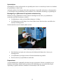
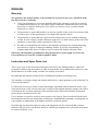
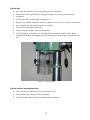
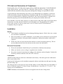
A 3008 M Flex
Skötselinstruktioner och reservdelar
Instructions and Spare Parts List
Bedienungsanleitung und Ersatzteilliste
Vår affärsidé
Machinery Scandinavia AB skapar mervärde genom att ge
sina kunder inom metallindustrin konkurrenskraft med
driftsäkra, effektiva och prisbilliga maskiner.
Our business idea
Machinery Scandinavia AB creates and delivers value for
their customers in the engineering industry by supplying them
with reliable, effective and competitive machines at all prices.
Unsere Geschäftsidee
Machinery Scandinavia AB stärkt die Wettbewerbsfähigkeit
seiner Kunden in der verarbeitenden Industrie mit
zuverlässigen, effektiven und preiswerten Maschinen.
2
INNEHÅLL – CONTENT – INHALT
SVENSKA .................................................................................................................................................... 5
Garanti..................................................................................................................................................... 5
Skötselinstruktioner och reservdelslista............................................................................................. 5
Säkerhetsföreskrifter ............................................................................................................................. 6
Generella säkerhetsföreskrifter............................................................................................................ 6
Vid installation...................................................................................................................................... 6
Vid användande ................................................................................................................................... 7
Vid service och underhåll..................................................................................................................... 7
CE-märkning och försäkran om överenskommelse ........................................................................... 8
Installation .............................................................................................................................................. 8
Uppsättning.......................................................................................................................................... 8
Inkoppling............................................................................................................................................. 8
Smörjning............................................................................................................................................. 9
Manöverorgan......................................................................................................................................... 9
Inställning av spindelvarvtal................................................................................................................. 9
Maskin försedd med automatisk matning ............................................................................................ 9
Handhavande.......................................................................................................................................... 9
Handmatad borrning ............................................................................................................................ 9
Maskinmatad borrning ....................................................................................................................... 10
Justering av matningstillslag.............................................................................................................. 10
Automatisk reversering ...................................................................................................................... 11
Borrspindel......................................................................................................................................... 11
Spindelhylsa....................................................................................................................................... 12
Borttagning av fjäderhuset för spindelns utbalansering..................................................................... 12
Reparationer ...................................................................................................................................... 12
ENGLISH.................................................................................................................................................... 13
Warranty................................................................................................................................................ 13
Instruction and Spare Parts List......................................................................................................... 13
Safety Instructions............................................................................................................................... 14
General Safety instructions................................................................................................................ 14
During Installation .............................................................................................................................. 14
During Use ......................................................................................................................................... 15
During service and maintenance ....................................................................................................... 15
CE-Label and Declaration of Compliance.......................................................................................... 16
Installation ............................................................................................................................................ 16
Set-up ................................................................................................................................................ 16
Electrical Connection ......................................................................................................................... 16
Lubrication ......................................................................................................................................... 16
Speed selection .................................................................................................................................... 17
Setting the Spindle Speed ................................................................................................................. 17
Machines equipped with Automatic Feed.......................................................................................... 17
Handling ................................................................................................................................................ 17
Hand-fed Drilling ................................................................................................................................ 17
Machine-feed Drilling ......................................................................................................................... 17
Adjusting the Feed Coupling.............................................................................................................. 18
Automatic Reversing.......................................................................................................................... 18
Drill Spindle........................................................................................................................................ 19
Removing or Adjusting the Spring Housing to Balance the Spindle.................................................. 19
Repairs............................................................................................................................................... 20
3
DEUTSCH .................................................................................................................................................. 21
Garantie................................................................................................................................................. 21
Bedienungsanleitung und Ersatzteilliste........................................................................................... 21
Sicherheitshinweise............................................................................................................................. 22
Allgemeine Sicherheitshinweise ........................................................................................................ 22
Installation.......................................................................................................................................... 23
Bedienung.......................................................................................................................................... 23
Service und Wartung ......................................................................................................................... 24
CE-Kennzeichnung und Konformitätserklärung............................................................................... 24
Installation ............................................................................................................................................ 24
Aufstellung ......................................................................................................................................... 24
Anschluss........................................................................................................................................... 24
Schmierung........................................................................................................................................ 25
Bedienelemente.................................................................................................................................... 25
Spindeldrehzahl einstellen................................................................................................................. 25
Maschine mit automatischem Vorschub............................................................................................ 25
Bedienung............................................................................................................................................. 25
Mit manuellem Vorschub bohren ....................................................................................................... 25
Mit automatischem Vorschub bohren ................................................................................................ 26
Vorschubaktivierung einstellen .......................................................................................................... 26
Automatische Umkehrung ................................................................................................................. 27
Bohrspindel ........................................................................................................................................ 28
Spindelhülse ...................................................................................................................................... 28
Federgehäuse zum Spindelabgleich demontieren oder justieren ..................................................... 28
Reparaturen ....................................................................................................................................... 28
Oljerekommendationer - Oil recommendations - Öl......................................................................... 46
4
SVENSKA
Garanti
Vi garanterar för en tid av ett år, räknat från fakturadatum, för maskinens fullgoda
beskaffenhet på så sätt;
•
Att om någon del bevisligen blir obrukbar under garantitiden pga material- eller
fabrikationsfel, vi i eget val gratis antingen levererar fullgod del eller reparerar den gamla
mot att den sänds till vår verkstad på vår bekostnad och med av oss anvisad transportör.
•
Köparen eller agenten skall meddela oss snarast när ett garantifall uppstår för att ge oss
möjligheter att undersöka och åtgärda felet.
•
Köparen eller agenten skall inte själv åtgärda felet på plats utan att först ha kontaktat oss.
Om sådan reparation görs utan vårt godkännande sker detta helt på köparens eller
agentens risk som då får stå för kostnaderna.
•
För fel på maskinen som uppkommit genom yttre åverkan, slitage, vanskötsel eller
felaktigt handhavande påtar vi oss inget ansvar. Vi påtar oss inte heller någon
ersättningsskyldighet för andra direkta eller indirekta kostnader i samband med
garantifall.
I övrigt gäller Machinery Scandinavia AB generella leveransvillkor, Allmänna
Leveransbestämmelser NL 92 och Orgalime S 2000.
Skötselinstruktioner och reservdelslista
Denna skötselinstruktion och reservdelslista är utarbetad för Er som använder, ansvarar eller ger
service för denna maskin. Därför bör den som närmast ansvarar eller använder maskinen ha
bekväm tillgång till denna skötselinstruktion och reservdelslista.
Läs instruktionen innan Ni installerar och startar maskinen. Maskinen är enkelt och robust
byggd, men vi kan inte garantera dess perfekta funktion om den behandlas felaktigt. Gör er
därför väl förtrogen med maskinen och prova de olika detaljerna i manöversystem och
inställningar. Behärskar Ni maskinen kan Ni också utnyttja dess egenskaper fullt ut och få
maximal livslängd på alla ingående komponenter.
Varje maskins noggrannhet och kapacitet provas vid fabriken. Erfaren personal kontrollerar både
mekaniska och elektriska funktioner enligt ett standardiserat program. Vi kan därför garantera att
utförandet är på en hög nivå.
Följer Ni våra anvisningar och ert goda omdöme är vi övertygade om att Ni blir nöjda med Er
nya maskin. Skulle trots allt problem uppstå, kontakta vår återförsäljare eller oss direkt.
5
Säkerhetsföreskrifter
Rätt använd är denna maskin en av de bästa med avseende på design och säkerhet. Varje maskin
som används felaktigt kan emellertid alltid utgöra en olycksrisk. Det är absolut nödvändigt att de
som använder maskinen har lärt sig hur man använder den korrekt. De skall läsa och förstå denna
manual såväl som alla skyltar som finns på maskinen. Underlåtenhet att följa
säkerhetsföreskrifter kan orsaka olyckstillbud.
Varning!
Felanvändning av denna maskin kan orsaka allvarliga personskador.
Maskinen måste installeras och underhållas korrekt.
Generella säkerhetsföreskrifter
•
Alla maskiner med roterande verktyg kan orsaka olyckor. Det är därför viktigt att Du som
operatör är medveten om olycksrisken och följer följande föreskrifter.
•
Använd kläder och personlig skyddsutrustning som gör att Du inte kan fastna i det
roterande verktyget.
•
Använd skyddsglasögon om risk för spån- eller kylvätskestänk föreligger eller om lokala
regler finns om detta.
•
Håll rent runt maskinen så att du inte snubblar och faller mot roterande verktyg.
•
Se till att arbetsstycket är ordentligt låst i bordet. Använd aldrig handen för att hålla
arbetsstycket.
•
Se alltid till att maskinens strömbrytare står i läge 0 när du skall byta verktyg eller
rengöra maskinen. Borsta aldrig bort spån under tiden maskinen arbetar.
•
Använd korrekta verktyg. Se till att rätt varvtal och rätt matning är inställd för verktyget.
Försäkra Dig om att verktyget är avsett för arbetet.
•
Se till att huvud och bord är ordentligt fastlåsta före start.
Vid installation
•
Undvik att installera maskinen i fuktig, smutsig eller dåligt belyst miljö.
•
Se till att maskinen har alla nödvändiga skydd.
•
Elektriska installationer skall utföras av behörig elektriker.
•
Försäkra Er om att maskinen är stadigt uppställd eller förankrad.
6
Vid användande
•
Använd aldrig maskinen om den saknar nödvändiga skydd.
•
Följ gängse regler för maskinanvändning avseende personlig skyddsutrustning.
•
Undvik om möjligt att använda arbetshandskar.
•
Arbeta inte i maskinen med löst sittande klädsel eller smycken. Använd hårnät om
nödvändigt.
•
Sträck Dig aldrig över maskinen när den är igång.
•
Lämna aldrig maskinen påslagen.
•
Stoppa alltid maskinen när den inte används.
•
Använd borrskydd. Borrskydd levereras bara till maskiner med CE-märkning. Vid byte
av verktyg trycks borrskyddet uppåt och viks åt sidan.
Bild 1. Borrskydd
Vid service och underhåll
•
Se alltid till att spänningen till maskinen är frånslagen.
•
Följ alltid instruktionerna i denna manual.
•
Modifiera aldrig maskinen utan att rådfråga vår återförsäljare
7
CE-märkning och försäkran om överenskommelse
Om denna maskin är CE-märkt betyder det att den vid leverans uppfyller de tillämpliga
”Väsentliga Hälso- och Säkerhetskrav” som anges i EU:s så kallade Maskinsäkerhetsdirektiv.
Om förändringar görs som påverkar maskinens säkerhet ansvarar den som utför förändringarna
för dessa.
Som bevis på att kraven uppfylls medlevereras en EU-försäkring om överenskommelse, utfärdad
av Machinery Scandinavia AB för varje enskild maskin. Denna EU-försäkran omfattar också
tillbehör, tillverkad av Machinery Scandinavia AB. Dokumentationen är en värdehandling som
skall bevaras väl och som alltid ska medfölja maskinen vid försäljning.
Om maskinen används för andra ändamål eller med andra tillbehör än som anges i denna
instruktion måste säkerheten säkerställas i varje enskilt fall. Ansvarig är den som utför den och
kan i vissa fall kräva ny CE-märkning och utfärdande av ny EU-försäkran om överenskommelse.
Installation
Uppsättning
•
Kontrollera att maskinen inte har skadats under transporten. Om så är fallet kontakta
omedelbart vår återförsäljare.
•
Placera maskinen på ett stabilt underlag. Ett mjukt mellanlägg av gummi eller dylikt kan
med fördel läggas mellan maskinens fotplatta och underlaget. Förankra maskinen med
bultar om så fordras.
•
Tvätta bort det rostskyddsmedel som maskinen är behandlad med vid leverans. Använd
inte för mycket lösningsmedel eftersom lösningsmedel även löser infettning. Tvätta
verktygsinfästningen i borrspindeln speciellt noga.
Inkoppling
•
Inkopplingen skall alltid utföras av behörig elektriker.
•
Kontrollera att rätt spänning tillförs maskinen.
•
Koppla enligt bifogat kopplingsschema. Koppla in direkt på huvudmotorns motorskydd
eller, när det gäller flerspindliga maskiner, i en kopplingsdosa.
•
Kontrollera att borrspindeln har rätt rotationsriktning.
8
Smörjning
Samtliga kullager och kugghjul är infettade från fabrik.
•
Kontrollera växellådans infettning efter några års drift.
•
Smörj matningsväxellådan (för maskiner med sådan) och övriga rörliga delar genom
smörjkopparna.
Matningsväxellådans snäckväxel ligger i ett oljebad. Fyll på olja genom påfyllningshålet till
mitten på nivåglaset (ca 0,3 liter). Lämplig olja bör en viskositet av 11 °E vid 50 °C. Se separat
oljerekommendation.
OBS! Maskiner med automatisk matning levereras utan olja i matningsväxellådan.
Manöverorgan
Inställning av spindelvarvtal
Varvtalen ställs in med de två växelhandtagen på spindelhusets vänstra sida. Ställ in enligt
skylten på framsidan. Maskinen måste stå still när växling görs.
Skulle någon växel vara svår att få i läge, rotera spindelnosen för hand.
Maskin försedd med automatisk matning
Matningshastigheten ställs in med ratten på matarlådans högra sida. Inställning kan göras under
gång, dock ej under belastning.
Ratten kan inte vridas direkt från högsta till lägsta matningshastighet eller tvärtom, utan man
måste alltid gå över de mellanliggande lägena.
Matningen går automatiskt i när borrtryck uppstår. Vid uppnått borrdjup återgår spindeln till sitt
översta läge.
Handhavande
Maskinen är försedd med en 2-hastighetsmotor.
•
Ställ in önskat läge (1 eller 2) med vredet;
•
Välj spindelhastighet med de två växelhandtagen på maskinens vänstra sida. Se skylten
på maskinens framsida.
Rotera spindelnosen för hand om någon växel är svår att få i läge.
OBS! Maskinen får inte växlas under gång.
Handmatad borrning
•
Klokopplingen (1), bild 2, vid handspaken ska vara inskjuten.
•
Ställ in borrdjupet med hjälp av skalan och det låsbara handtaget på maskinens framsida.
9
Maskinmatad borrning
Maskinmatningen ger en komplett arbetscykel med endast ett handgrepp. Arbetscykeln erhålls
genom att borrspindeln matas ner mot arbetsstycket. När borrtryck uppstår kopplas
maskinmatningen in och maskinen borrar till inställt borrdjup. Därefter återgår borrspindeln till
utgångsläget.
Maskinmatningens repeternoggrannhet är 0,1−0,2 mm. Vid behov kan matningen avbrytas gen
att man håller emot någon av handmatningsspakarna.
Inställning av maskinmatat borrdjup:
•
Lås borrdjupskalan i sitt översta läge.
•
Dra ut kopplingen (1) åt höger.
•
Lossa de två insexskruvarna (2) i handspaksfästet.
•
Mata ner spindeln till önskat borrdjup. Vid maskinmatning går spindeln ca 3 mm längre
än vad som är inställt.
Exempel: Om borrdjupet 20 mm ska ställas in och 0-punkten är 100 mm, ställ in borrdjupet på
77 mm. OBS! Den mekaniska konstruktionen gör att man ställer in på detta sätt.
•
För den inre ringens (3) anslagsklack (4) mot stoppinnens (5) ovansida.
•
Vrid den räfflade ringens (6) stopp mot anslagsklackens ovansida.
•
Dra åt de båda insexskruvarna innan spindeln släpps upp.
•
Kontrollmät och efterjustera borrdjupet.
2
4
5
1
3
6
Bild 2 Inskjuten koppling
Bild 3 Utdragen koppling
Justering av matningstillslag
Matningen är från fabrik inställd på ett sådant att maskinen inte kan överlastas. Efter en tids
användning kan emellertid kopplingen behöva justeras. Justering:
•
Ta bort locket på klokopplingen.
•
Dra axelmuttern medurs till nästa läge på låsbrickan. Detta ger en större matningskraft.
Vid borrning med klena verktyg är det lämpligt att använda lägre ansättningskraft för matningen.
Justeringen sker enligt ovan, men axelmuttern dras moturs. Vid för högt borrtryck fungerar
kopplingen som överlastningsskydd.
10
Automatisk reversering
•
Tryck på strömbrytaren till läge gängning, lyser vid påslaget läge (se bild 4).
•
Ställ in önskat gängdjup med borrdjupsstoppet.
Vid inställt gängdjup ändrar spindeln automatiskt rotationsriktning genom att faserna till motorn
ändras. Spindelvarvtalet bör inte överstiga det nedre varvtalsområdet 65-670 rpm. För högre
kvalitet på gängningen rekommenderar vi att flytande gängtapphållare används.
OBS! Automatisk matning skall inte användas vid gängreversering.
6
4
5
1
2
3
Bild 4: (1) Start, (2) Stopp, (3) Auto Reversering på/av.
(4) Varvtalsjusteringsratt, (5) Nöd Stopp,
(6) Digital djupmåttskala.
Borrspindel
Borrspindeln är lagrad i nedre kullagret. Efter ett års drift rekommenderar vi att man tar ur
spindelhylsan och ansätter lagren om så erfordras.
•
Dra ut matningslådan ett stycke så att kugghjulet släpper från spindelhylsan.
•
Ansätt lagren.
11
Spindelhylsa
Spindelhuset är slitsat på framsidan vid spindelhylsan. Justera eventuellt spel med de tre bultarna
på spindelhusets vänstra sida.
Används maskinen för fräsning eller andra operationer som medför vibrationer, rekommenderar
vi att låsningen runt spindelhylsan justeras hårdare för att förhindra förslitning av spindellagren.
Borttagning av fjäderhuset för spindelns utbalansering
Håll fast en tång i fjäderhusets två hål. Skruva samtidigt bort den skruv på spindelhusets
undersida som håller fast huset (se bild 5).
•
Låt fjäderhuset vrida sig så att fjädern kommer i viloläge.
•
Vrid fjäderhuset medurs något varv så att fjädern lossar från den skruv som håller den
fästad på matningsaxeln.
Nu kan fjäderhuset med isittande fjäder tas bort.
Bild 5. Borttagning av fjäderhus
•
Sätt fjäderhuset på plats och vrid moturs tills fjäderns hål hakar fast i skruven på
matningsaxeln.
•
Vrid fjäderhuset ytterligare moturs till önskad utbalansering erhålls.
•
Dra fast skruven på spindelhusets undersida.
Reparationer
Vid rätt handhavande, underhåll och skötsel är inga reparationer förutom eventuellt byte av
fjäderhus nödvändiga. Skulle ändå reparationer bli nödvändiga ger reservdelsbilderna god
vägledning. Uppstår osäkerhet, kontakta vår återförsäljare eller vår fabrik.
12
ENGLISH
Warranty
We guarantee the utmost quality of the machine for a period of one year, calculated from
the date of invoice, such that:
•
If any part should prove to become unusable during the warranty period due to material
or manufacturing defects, we will either supply an adequate replacement part at our own
discretion or repair the defect part if it is sent to our factory on our cost and with the
transporter we advice.
•
The purchaser or agent shall notify us as soon as possible in the event of a warranty claim
in order to give us the opportunity to investigate and repair the defect.
•
The purchaser or agent shall not repair the defect themselves on site without contacting
us first. If such a repair is made without our approval, it is made entirely at the risk of the
purchaser or agent who is then responsible for the costs.
•
We take no responsibility for defects to the machine resulting from external tampering,
wear and tear, neglect or improper handling. Neither do we take responsibility for
compensating other direct or indirect costs in connection with the warranty claim.
Otherwise, the Machinery Scandinavia AB general delivery terms apply, as well as the
General Delivery Terms NL 92 and Orgalime S 2000.
Instruction and Spare Parts List
This is your copy of the instructions and spare parts list for the drilling machine. It has been
prepared for those using the machine or who are responsible for its maintenance and service and
should therefore be made readily available for all those concerned.
Read through the manual carefully before installing the machine and starting it up.
The machine is of simple design and robustly built, but we cannot guarantee perfect function if it
is incorrectly handled.
It is therefore necessary to make yourself thoroughly acquainted with its functions and to carry
out practical tests on the various parts in the control system and the machine settings. Once these
are mastered, the excellent properties of the machine can be fully utilized and the component
parts will give maximum service life.
Every machine is tested for accuracy and capacity at the factory. Experienced staff checks both
the mechanical and electrical functions according to a standardized programme, meaning that we
can guarantee workmanship of the highest and most consistent quality.
By following our directions and your own good judgement, we are convinced that your new
machine will give every satisfaction. However, should any problems arise, please do not hesitate
to contact our dealer or us.
13
Safety Instructions
When used correctly, this is one of the best machines in terms of design and safety. However,
any machine that is used improperly can always pose a safety risk. It is absolutely necessary that
those persons using the machine have learned how to use it correctly. They should read and
understand this material as well all the signs on the machine. Neglecting to follow the safety
instructions can pose the risk of an accident.
Warning!
Improper use of this machine can cause serious personal injury.
The machine must be installed and maintained correctly.
General Safety instructions
All machines with rotating parts can cause accidents. Therefore, it is important that as an
operator, you are aware of the risk of an accident and follow the guidelines below:
•
Wear clothing and personal safety equipment that cannot get caught in the rotating
drilling and tapping tools.
•
Use eye protection if there is a risk of shavings or coolant splattering, or if there are local
regulations in this regard.
•
Keep the area around the machine clean so that you do not trip and fall against the
rotating tool.
•
Make sure that the work piece is properly fastened to the table. Never use your hands to
hold the work piece.
•
Always make sure that the machine's electric switch is in the 0 position when changing
the drilling and tapping tools or cleaning the machine. Never brush shavings away while
the machine is working.
•
Use proper drilling and tapping tools. Make sure that the proper speed and the proper
feed rate is set for the drilling and tapping tools. Be sure that the drilling and tapping
tools is intended for the work you are doing.
•
Make sure that heads and tables are properly locked in place before starting.
During Installation
•
Avoid installing the machine in damp, dirty or poorly lit environments.
•
Make sure that the machine has all the necessary protection.
•
Electrical installations should be performed by authorized electricians.
•
Be sure that the machine is set up securely or anchored in place.
14
During Use
•
Never use the machine if it is missing the necessary protection.
•
Follow the current regulations for using the machine, in terms of personal safety
equipment.
•
As far as possible, avoid using working gloves.
•
Do not work with the machine with loose clothing or jewelry. Use a hair net if necessary.
•
Never stretch over the machine when it is running.
•
Never leave the machine turned on.
•
Always stop the machine when not being used.
•
Use a drill guard. A drill guard is only supplied for machines with CE-label. When
changing the drilling and tapping tools, the drill guard is pushed upward and bent to the
side.
Picture 1. Drill guard
During service and maintenance
•
Always make sure that the power to the machine is off.
•
Always follow the instructions in this manual.
•
Never alter the machine without consulting our retail dealer.
15
CE-Label and Declaration of Compliance
If this machine has a CE-label, then it upon delivery fulfils the appropriate "Critical Health and
Safety Requirements" specified in the EU:s Machine Safety Directive. If changes are made
which affect the machine's safety, the person making these changes is responsible for them.
As proof that the requirements have been met, an EU Declaration of Compliance is delivered
with each machine, prepared by Machinery Scandinavia AB. This EU declaration also covers
accessories manufactured by Machinery Scandinavia AB. The documentation is valuable and
should be properly preserved and should always accompany the machine when sold.
If the machine is used for other purposes or with accessories other than what is specified in these
instructions, its safety must be ensured in each individual case. Responsibility lies with the
person who operates it, and in certain cases a new CE-label or new EU Declaration of
Compliance may be required.
Installation
Set-up
•
Check that the machine has not been damaged during transport. If this is the case, contact
our retail dealer immediately.
•
Place the machine on a stable foundation. A soft rubber pad or similar item can be placed
between the machine's foot plate and the foundation. Anchor the machine with bolts if
required.
•
Wash away the rust-protection that the machine is treated with during delivery. Do not
use too much solvent, since the solvent can also remove the lubrication.
Electrical Connection
•
Electrical installations should always be performed by authorized electricians.
•
Make sure that the correct voltage is supplied to the machine.
•
Set up the electrical connections according to the attached circuitry diagram. Connect the
electricity with the attached cable and CEE connector.
Lubrication
All ball bearings and gear wheels are lubricated at the factory. Check the gear box's lubrication
after several years of use.
Lubricate the feed gear box (for machines equipped with one) and other movable parts by using
the lubricating cups.
The feed gear box's worm gear sits in an oil bath. Add oil via the filling hole up to the middle of
the level indicator (approx. 0.3 liters). Proper oil should have a viscosity of 11 °E at 50 °C. See
separate oil recommendations.
NOTE! Machines with automatic feed are not supplied with oil in the feed gearbox.
16
Speed selection
Setting the Spindle Speed
The rotation speed is set using the gear lever on the left side of the spindle case. Set it according
to the sign on the front side. The machine must be at a stand still to make the switch. If any of
the gears are difficult to get into position, rotate the spindle nose manually. By setting the
machine to “On” position and turning the speed knob at the front, it can be set to the ultimate
speed by checking the speed display at the top of the machine front (picture 4).
Machines equipped with Automatic Feed
The feed speed is set using the knob on the right side of the feeding box. The feeding rate can be
set while the machine is in operation, but not when loaded.
The knob cannot be turned directly from the highest to the lowest feed rate, or vice versa. You
always have to go through the middle positions.
Feeding occurs automatically when drill pressure occurs and the feed handle is pressed
furthermore to a click stop. When the desired drill depth is achieved, the spindle returns to its
upper position.
Handling
The machine is equipped with a 1-speed motor.
Select the spindle speed using the gear lever on the left side of the machine. See the sign on the
front side of the machine.
If any of the gears are difficult to get into position, rotate the spindle nose manually.
Set the Machine in on position by the push button marked 1 at the front and 0 to turn off
(picture 4).
NOTE! The machine cannot be shifted during operations.
Hand-fed Drilling
The claw coupling (1), picture 2, on the hand lever must be pushed in.
Set the drill depth using the scale and the lockable lever on the front of the machine. Also, the
digital depth scale shows a more accurate depth and adjustment possibilities
Machine-feed Drilling
Machine feeding provides a complete work cycle with only one handle. The work cycle is
obtained by feeding the drill spindle down against the work piece. When drill pressure appears,
the machine feed is connected and the machine drills to the set drilling depth. The drilling
spindle then returns to the withdrawal position. The machine feed's repeated accuracy is 0.1 – 0.2
mm. If required, feeding can be cancelled by holding back any of the hand feed levers.
Setting the machine-fed drill depth:
•
Lock the drill depth scale in its upper position.
•
Remove the coupling (1) towards the right.
•
Loosen the two female screws (2) in the hand lever fastener.
•
Feed the spindle down to the desired drilling depth. In the event of machine feeding, the
spindle goes approximately 3 mm longer than what is set.
17
Example: When setting a drilling depth of 20 mm and the 0-point is 100 mm, set the drilling
depth to 77 mm. NOTE! The mechanical design means that it has to be set this way.
•
Push the inner ring's (3) stop heel (4) against the top side of the stop pin (5).
•
Turn the grooved ring's (6) stopper toward the top of the stop heel.
•
Tighten both of the female screws before releasing the spindle.
•
Check the measurements and adjust the drilling depth.
2
4
5
3
1
6
Picture 2. Inserted coupling
Picture 3. Withdrawn coupling
Adjusting the Feed Coupling
The feed is set at the factory so that the machine cannot be overloaded. However, after using the
machine for a while, the coupling may need to be adjusted. Adjusting:
•
Remove the top on the claw coupling.
•
Rotate the ring nut clockwise to the next position on the locking washer. This provides
greater feeding power.
•
When drilling with sensible boring tools, it may be necessary to use a lower power for
feeding. Adjustments are made as above, but the ring nut is rotated counter-clockwise. In
the event that the drill pressure is too high, the coupling acts as an overload protection.
Automatic Reversing
•
Push the power switch to the threading position. It will light up when used (see
picture 4).
•
Set the desired threading depth with the drilling depth stopper.
If the thread depth is set, the spindle automatically changes its direction of rotation by changing
the phases to the motor.
The speed of the spindle should not exceed the lower work range 65 -670 rpm in order to keep
up the torque. In order to get better quality threading, we recommend using a floating tap
wrench.
NOTE! Do not use automatic feeding during reverse threading.
18
6
4
5
1
2
3
Picture 4: (1) Start, (2) Stop, (3) Auto Reverse on/off,
(4) Speed adjustment knob, (5) Emergency Stop,
(6) Digital Depth Scale.
Drill Spindle
The drill spindle is mounted in the upper and lower ball bearing. After one year of operation, we
recommend removing the spindle sleeve and adjusting the bearings if necessary.
•
Remove the feed case a little bit so that the gear wheel is released from the spindle
sleeve.
•
Adjust the bearings.
Removing or Adjusting the Spring Housing to Balance the Spindle
•
Hold a pair of pliers in the two holes of the spring housing. At the same time, unscrew
the screw on the underside of the drill head, which holds the housing in position
(picture 5).
•
Let the spring housing unwind so that the spring reaches a resting position.
•
Turn the spring housing clockwise a few times so that the spring comes loose from the
screw holding it attached to the feeding shaft. Now the spring housing can be removed
with the spring in it.
19
Picture 5: Removing the spring case
•
Put the spring in place and turn clockwise until the spring's hole hooks onto the screw on
the feeding shaft.
•
Turn the spring housing clockwise some more until the desired balancing has been
obtained.
•
Tighten the screw on the underside of the drill head.
Repairs
With proper handling, maintenance and care, no repairs are needed apart from changing the
spring case when necessary. Should repairs be necessary, the spare parts picture can be used as
guideline. If you are uncertain, please contact our retailer or our factory.
20
DEUTSCH
Garantie
Wir garantieren für die Dauer eines Jahres nach Rechnungsdatum den einwandfreien
Zustand der Maschine zu folgenden Bedingungen:
•
Ist innerhalb des Garantiezeitraums eine Komponente aufgrund von Material- oder
Fabrikationsfehlern nachweislich unbrauchbar, liefern wir nach eigenem Ermessen
entweder ein intaktes Ersatzteil oder reparieren die defekte Komponente in unserer
Werkstatt. Der Versand zum Hersteller ist für den Kunden kostenlos und muss mit einem
vom Hersteller angegebenen Spediteur erfolgen.
•
Käufer oder Vertreter müssen uns von einem Garantiefall umgehend in Kenntnis setzen,
damit wir den Fehler untersuchen und beheben können.
•
Käufer / Vertreter dürfen nicht selbst versuchen, den Fehler zu beheben, ohne zuerst mit
uns in Verbindung zu treten. Wenn Reparaturen ohne unsere Zustimmung ausgeführt
werden, geschieht dies auf eigenes Risiko des Käufers / Vertreters. Eventuell anfallende
Kosten werden von Ihnen getragen.
•
Wir übernehmen keine Garantie für Maschinenfehler, die durch äußere Einwirkung,
Verschleiß, mangelnde Wartung oder unsachgemäße Verwendung entstehen. Wir
übernehmen keinerlei Entschädigungspflicht für andere direkte oder indirekte Kosten, die
im Zusammenhang mit einem Garantiefall entstehen.
Darüber hinaus gelten die Allgemeinen Lieferbedingungen von Machinery Scandinavia AB
(Allmänna Leveransbestämmelser NL 92 und Orgalime S 2000).
Bedienungsanleitung und Ersatzteilliste
Diese Bedienungsanleitung und Ersatzteilliste richtet sich an Maschinenbenutzer, Maschinenverantwortliche und Servicepersonal. Maschinenverantwortliche oder Maschinenbenutzer sollten
jederzeit auf diese Dokumentation zugreifen können.
Lesen Sie diese Anleitung, bevor Sie die Maschine installieren und in Betrieb nehmen.
Die Maschine ist einfach und robust konstruiert. Bei unsachgemäßer Behandlung können wir
eine einwandfreie Funktionsweise jedoch nicht garantieren. Machen Sie sich daher mit der
Maschine vertraut und testen Sie die einzelnen Bedienelemente und Einstellungsmöglichkeiten.
Durch eine umfassende Beherrschung der Maschine können Sie deren Leistungsvermögen voll
ausschöpfen und die maximale Lebensdauer aller enthaltenen Bauteile gewährleisten.
Genauigkeit und Leistung aller Maschinen werden im Herstellungswerk getestet. Anhand eines
standardisierten Ablaufs kontrolliert erfahrenes Personal die mechanischen und elektrischen
Funktionen. Auf diese Weise können wir höchste Qualität garantieren.
Wenn Sie unsere Anweisungen befolgen und Ihre Erfahrungen nutzen, werden Sie beim Umgang
mit dieser Maschine mehr als zufrieden sein. Sollten trotzdem Probleme auftreten, wenden Sie
sich an unseren Händler oder direkt an uns.
21
Sicherheitshinweise
Bei korrekter Verwendung ist diese Maschine ein Spitzengerät in punkto Design und Sicherheit.
Unsachgemäß verwendete Maschinen stellen hingegen einen beachtlichen Risikofaktor dar. Es
ist unbedingt erforderlich, dass das Bedienungs- und Wartungspersonal der Maschine über
dessen korrekte Funktionsweise unterrichtet wurde. Das Bedienungs- und Wartungspersonal
muss vor dem Arbeiten mit der Maschine diese Anleitung sowie alle Maschinenschilder lesen.
Eine Nichtbeachtung der Sicherheitshinweise stellt eine potenzielle Gefahrensituation dar.
Warnung!
Der unsachgemäße Umgang mit dieser Maschine kann schwere Personenschäden nach
sich ziehen.
Die Maschine muss korrekt installiert und gewartet werden.
Allgemeine Sicherheitshinweise
Alle Maschinen mit rotierenden Werkzeugen können Unfälle verursachen. Sämtliches
Bedienpersonal muss sich daher dieser Unfallgefahr bewusst sein und die folgenden Hinweise
beachten:
•
Tragen Sie nur Arbeitsbekleidung und persönliche Schutzausrüstung, mit der Sie nicht
am rotierenden Werkzeug hängenbleiben können.
•
Tragen Sie eine Schutzbrille, wenn Späne oder Kühlflüssigkeit herumfliegen oder
austreten können bzw. wenn dies durch lokale Sicherheitsbestimmungen vorgeschrieben
wird.
•
Halten Sie den Bereich um die Maschine sauber. Andernfalls besteht Stolpergefahr mit
anschließender Berührung rotierender Werkzeuge.
•
Achten Sie darauf, dass das Werkstück fest auf dem Bohrtisch verriegelt ist. Halten Sie
Werkstücke niemals mit der Hand fest.
•
Vergewissern Sie sich, dass sich der Maschinenschalter in der Stellung "0" befindet,
wenn Sie Werkzeuge wechseln oder die Maschine reinigen. Bürsten Sie niemals Späne
ab, während die Maschine in Betrieb ist.
•
Setzen Sie die korrekten Werkzeuge ein. Achten Sie darauf, dass für das Werkzeug die
richtige Drehzahl und der richtige Vorschub eingestellt sind. Vergewissern Sie sich, dass
das Werkzeug für die jeweilige Verwendung vorgesehen ist.
•
Achten Sie darauf, dass Bohrkopf und Bohrtisch vor Arbeitsbeginn fest verriegelt sind.
22
Installation
•
Die Maschine sollte nicht in feuchten, schmutzigen oder schlecht ausgeleuchteten
Umgebungen installiert werden.
•
Achten Sie darauf, dass die Maschine stets mit allen erforderlichen Schutzvorrichtungen
versehen ist.
•
Elektrische Installationen sind von einem ausgebildeten Elektriker vorzunehmen.
•
Vergewissern Sie sich, dass die Maschine stabil aufgestellt oder verankert ist.
Bedienung
•
Verwenden Sie die Maschine nur, wenn alle erforderlichen Schutzvorrichtungen
vorhanden sind.
•
Befolgen Sie beim Umgang mit der Maschine die allgemeingültigen Regeln zur
persönlichen Schutzausrüstung.
•
Soweit möglich, keine Arbeitshandschuhe verwenden.
•
Arbeiten Sie nicht an der Maschine mit loser Bekleidung oder Schmuckgegenständen.
Falls erforderlich, tragen Sie ein Haarnetz.
•
Beugen Sie sich nie über eine im Betrieb befindliche Maschine
•
Lassen Sie die Maschine nie unbeaufsichtigt laufen.
•
Halten Sie die Maschine stets an, wenn Sie nicht benutzt wird.
•
Verwenden Sie einen Bohrschutz. Ein Bohrschutz wird nur mit Maschinen ausgeliefert,
die eine CE-Kennzeichnung besitzen. Beim Werkzeugwechsel drücken Sie den
Bohrschutz nach oben und klappen ihn zur Seite.
Abb. 1.
Bohrschutz
23
Service und Wartung
•
Trennen Sie die Maschine stets von der Stromquelle, bevor Sie Arbeiten an ihr ausführen.
•
Befolgen Sie stets die Anweisungen in diesem Dokument.
•
Nehmen Sie ohne vorherige Rücksprache mit unserem Händler keinerlei Änderungen an
der Maschine vor.
CE-Kennzeichnung und Konformitätserklärung
Wenn diese Maschine eine CE-Kennzeichnung besitzt, dann erfüllt Sie bei ihrer Lieferung die
”grundlegenden Gesundheits- und Sicherheitsvorgaben” der EU-Richtlinie zur
Maschinensicherheit. Wenn Änderungen vorgenommen werden, die die Maschinensicherheit
beeinträchtigen, trägt derjenige die Verantwortung, der diese Änderungen ausgeführt hat.
Als Beleg dafür, dass alle Vorgaben erfüllt wurden, liegt jeder Maschine eine von Machinery
Scandinavia AB ausgefertigte EU-Konformitätserklärung bei. Diese EU-Erklärung umfasst auch
Zubehör, das von Machinery Scandinavia AB hergestellt wird. Diese Dokumentation stellt eine
wichtige Urkunde dar, die gut aufzubewahren und der Maschine bei einem Verkauf stets
beizulegen ist.
Wenn die Maschine zu anderen Zwecken oder mit anderem Zubehör eingesetzt wird als in dieser
Anleitung angegeben, ist die Sicherheit in jedem einzelnen Fall zu gewährleisten. Verantwortlich
dafür ist die jeweils ausführende Person. In bestimmten Fällen kann eine neue CEKennzeichnung und die Ausfertigung einer neuen EU-Konformitätserklärung erforderlich sein.
Installation
Aufstellung
Kontrollieren Sie die Maschine auf eventuelle Transportschäden. Setzen Sie sich bei
Beschädigungen umgehend mit unserem Händler in Verbindung.
Stellen Sie die Maschine auf einer stabilen Unterlage auf. Es empfiehlt sich, zwischen
Grundplatte und Unterlage eine weiche Zwischenlage aus Gummi o.ä. zu platzieren. Falls
erforderlich, verankern Sie die Maschine mit Bolzen im Boden.
Waschen Sie das Rostschutzmittel ab, mit dem die Maschine im Lieferzustand behandelt ist.
Setzen Sie dabei nicht zu viel Lösungsmittel ein, da auf diese Weise die Schmierung entfernt
werden kann. Reinigen Sie die Werkzeughalterung in der Bohrspindel besonders gründlich.
Anschluss
•
Der Anschluss ist stets von einem ausgebildeten Elektriker vorzunehmen.
•
Kontrollieren Sie, ob die Maschine mit der richtigen Spannung versorgt wird.
•
Nehmen Sie den Anschluss anhand des beiliegenden Schaltplans vor.
•
Schließen Sie den Motorschutz des Hauptmotors direkt oder bei mehrspindligen
Maschinen an einer Anschlussdose an.
•
Überprüfen Sie, ob die Drehrichtung der Bohrspindel korrekt ist.
24
Schmierung
Alle Kugellager und Zahnräder sind werkseitig geschmiert.
•
Kontrollieren Sie die Schmierung des Getriebes nach mehreren Jahren Betrieb.
•
Schmieren Sie das Vorschubgetriebe (falls vorhanden) sowie alle anderen beweglichen
Teile über die Schmierbuchsen.
Das Schneckengetriebe des Vorschubgetriebes befindet sich in einem Ölbad. Füllen Sie durch
das Füllloch Öl bis zur Mitte das Schauglases auf (ca. 0,3 l). Geeignetes Öl sollte eine Viskosität
von 11°E bei 50 °C aufweisen (siehe separate Ölempfehlung).
HINWEIS! Maschinen mit automatischem Vorschub werden ohne Öl im Vorschubgetriebe
geliefert.
Bedienelemente
Spindeldrehzahl einstellen
Die Drehzahl wird mit Hilfe der beiden Griffe auf der linken Seite des Spindelgehäuses
eingestellt. Richten Sie sich dabei nach dem Schild auf der Vorderseite. Zum Wechseln der
Drehzahl muss die Maschine still stehen.
Wenn eine Einstellung nur schwer vorgenommen werden kann, drehen Sie die Spindelnase per
Hand.
Maschine mit automatischem Vorschub
Die Vorschubgeschwindigkeit wird über das Rad auf der rechten Seite der Vorschubeinheit
eingestellt. Diese Einstellung kann während des Betriebs, jedoch nicht bei Belastung
vorgenommen werden.
Das Rad kann nicht direkt von der höchsten bis zur niedrigsten Vorschubgeschwindigkeit
gedreht werden, sondern nur über die dazwischen liegenden Stellungen.
Der Vorschub findet automatisch statt, wenn ein Bohrdruck vorliegt. Bei erreichter Bohrtiefe
kehrt die Spindel in ihre oberste Stellung zurück.
Bedienung
Die Maschine ist mit einem Motor mit zweifacher Drehzahlumschaltung ausgestattet. Stellen Sie
per Schalter die gewünschte Drehzahl ein (1 oder 2).
Die Spindelgeschwindigkeit wird mit Hilfe der beiden Griffe auf der linken Maschinenseite
eingestellt. Richten Sie sich dabei nach dem Schild auf der Vorderseite.
Wenn eine Einstellung nur schwer vorgenommen werden kann, drehen Sie die Spindelnase per
Hand.
HINWEIS! Die Drehzahl darf während des Betriebs nicht gewechselt werden.
Mit manuellem Vorschub bohren
Die Klauenkupplung (1, siehe Abb. 2) am Handhebel muss hineingeschoben sein.
Stellen Sie die Bohrtiefe mit Hilfe der Skala und des Verriegelungshandgriffs auf der
Maschinenvorderseite ein.
25
Mit automatischem Vorschub bohren
Der automatische Vorschub ermöglicht einen vollständigen Arbeitszyklus mit nur einem
Handgriff. Beim Arbeitszyklus bewegt sich die Bohrspindel in Richtung Werkstück. Wenn ein
Bohrdruck entsteht, wird der automatische Vorschub aktiviert und die Maschine bohrt bis zur
eingestellten Bohrtiefe. Daraufhin kehrt die Bohrspindel in die Ausgangsposition zurück.
Die Wiederholgenauigkeit des automatischen Vorschubs beträgt 0,1-0,2 mm. Der Vorschub kann
auf Wunsch unterbrochen werden. Bewegen Sie dazu einen der manuellen Vorschubhebel.
So stellen Sie die Bohrtiefe bei automatischem Vorschub ein:
•
Verriegeln Sie die Bohrtiefenskala in ihrer obersten Stellung.
•
Ziehen Sie die Kupplung (1) nach rechts heraus.
•
Lösen Sie die beiden Inbusschrauben (2) an der Handhebelbefestigung.
•
Bewegen Sie die Spindel bis zur gewünschten Bohrtiefe herab. Bei automatischem
Vorschub bewegt sich die Spindel ca. 3 mm weiter als die Einstellung.
Beispiel: Wenn eine Bohrtiefe von 20 mm eingestellt werden soll und der Nullpunkt bei 100 mm
liegt, stellen Sie die Bohrtiefe auf 77 mm ein.
HINWEIS! Diese Einstellung wird durch die mechanische Konstruktion bedingt.
•
Führen Sie die Anschlagnase (4) des inneren Rings (3) zur Oberseite des Anschlagstifts
(5).
•
Drehen Sie den Anschlag des geriffelten Rings (6) bis zur Oberseite der Anschlagnase.
•
Ziehen Sie die beiden Inbusschrauben an, bevor die Spindel nach oben bewegt wird.
•
Kontrollieren Sie die Bohrtiefe und justieren Sie sie bei Bedarf.
2
4
5
3
6
Abb.2. Hineingeschobene Kupplung
Abb. 3. Herausgezogene Kupplung
Vorschubaktivierung einstellen
Der Vorschub ist werkseitig so eingestellt, dass die Maschine nicht überlastet werden kann.
Nachdem die Maschine eine Weile verwendet wurde, kann eine Einstellung der Kupplung
erforderlich sein. Gehen Sie dabei folgendermaßen vor:
26
1
•
Entfernen Sie den Verschluss der Klauenkupplung.
•
Drehen Sie die Achsmutter im Uhrzeigersinn bis zur nächsten Stellung an der
Steckscheibe. Dadurch wird eine höhere Vorschubkraft erzielt.
•
Beim Bohren mit feinen Werkzeugen empfiehlt es sich, eine geringere Vorschubkraft zu
wählen. Stellen Sie diese Kraft wie oben beschrieben ein. Die Achsmutter wird jedoch
gegen den Uhrzeigersinn angezogen. Bei zu hohem Bohrdruck dient die Kupplung als
Überlastschutz.
Automatische Umkehrung
•
Drücken Sie den Schalter in die Stellung für das Gewindeschneiden, leuchtet wenn “An“.
•
Stellen Sie mit dem Bohrtiefenanschlag die gewünschte Gewindetiefe ein.
Bei der eingestellten Bohrtiefe ändert die Spindel automatisch die Drehrichtung, indem die
Motorphasen gewechselt werden. Die Spindeldrehzahl sollte 65-670 U/min nicht überschreiten
um die gute Drehkraft zu erhalten. Um beim Gewindeschneiden eine höhere Qualität zu erzielen,
empfehlen wir den Einsatz schwimmender Gewindebohrerhalter.
HINWEIS! Bei einer Umkehrung darf kein automatischer Vorschub verwendet werden.
6
4
5
1
2
3
Abb. 4: (1) Start, (2) Stop, (3) Automatische Umkehr An/Aus,
(4) Einstellknopf der Drehzahlen, (5) Not-Aus,
(6) Digitale Tiefenmassskala.
27
Bohrspindel
Die Bohrspindel ist im oberen und unteren Kugellager gelagert. Nach einjährigem Betrieb
empfehlen wir, die Spindelhülse zu entnehmen und die Lager bei Bedarf nachzustellen. Ziehen
Sie die Vorschubeinheit ein Stück hinaus, sodass das Zahnrad nicht mehr in die Spindelhülse
greift. Stellen Sie die Lager nach.
Spindelhülse
Das Spindelgehäuse ist auf der Vorderseite an der Spindelhülse mit einem Schlitz versehen.
Justieren Sie ein eventuell vorliegendes Spiel mit den drei Schrauben auf der linken Seite des
Spindelgehäuses. Wenn die Maschine zum Fräsen oder für andere Anwendungen genutzt wird,
bei denen Vibrationen auftreten, empfehlen wir, die Befestigung um die Spindelhülse fester
einzustellen, um einen Verschleiß der Spindellager zu verhindern.
Federgehäuse zum Spindelabgleich demontieren oder justieren
•
Führen Sie eine Zange in die beiden Löcher des Federgehäuses. Lösen Sie gleichzeitig
die Verriegelungsschraube an der Unterseite des Spindelgehäuses (Abb. 5).
•
Lassen Sie das Federgehäuse sich drehen, damit die Feder in eine Ruhestellung gelangt.
•
Drehen Sie das Federgehäuse ein wenig im Uhrzeigersinn, damit sich die Feder von der
Schraube löst, mit der sie an der Vorschubachse befestigt wird.
Nun kann das Federgehäuse samt Feder abgenommen werden.
Abb. 5:
Federgehäuse demontieren
•
Setzen Sie das Federgehäuse ein und drehen Sie es gegen den Uhrzeigersinn, bis sich die
Löcher in der Feder an der Schraube der Vorschubachse verhaken.
•
Drehen Sie das Federgehäuse weiter gegen den Uhrzeigersinn, bis die gewünschte
Einstellung erreicht ist.
•
Ziehen Sie die Schraube an der Unterseite des Spindelgehäuses fest.
Reparaturen
Bei vorschriftsmäßiger Bedienung, Wartung und Pflege sind neben einem eventuellen Wechsel
des Federgehäuses keine Reparaturen erforderlich. Sollte dennoch Reparaturbedarf bestehen,
richten Sie sich nach den Ersatzteilabbildungen. Wenden Sie sich bei Unklarheiten an unseren
Händler oder unsere Werk.
28
Spindelhuvud
Drill head
Bohrkopf
Pos
1
Art. No.
2N01889
Benämning
Lagerlock
Description
Bearing cover
Benennung
Lagerschild
2
3S03325
Skruv MC6S 5x10
Screw MC6S 5x10
Schraube MC6S 5x10 4st/pcs
3
4B01890
Fläktkåpa
Fan cover
Ventilatordeckel
4
3S03287
Skruv MC6S 4x8
Screw MC6S 4x8
Schraube MC6S 4x8
5
2X08507-1
Spindelhus komplett Drill head complete
Bohrkopf komplett
6
2X08720-1
Snäckväxel komplett Worm gear
Schneckengetriebe
7
4L08589
Täckplåt
Cover plate
Abdeckblech
8
4U08918
Kåpa
Cover
Haube
9
4X00980
Spindelskydd
Drill guard
Bohrschutz
10
2N08551R
Ok
Quill collar
Spindeljoch
11a
3E60101
Digital mätskala
Digital display
Digitalanzeige
11b
4L08921
Fästplåt digital mäts. Mounting plate
Befestigungsblech
12
4L08949
Frontskylt
Front plate
Frontschild
13
4XS0653-1
Vxl.spak komplett
Gear handle compl.
Schalthebel komplett
14
3T08921
Fläktfilter
Fan filter
Ventilatorfilter
15
3E08905
Varvtalsdisplay
Tachometer
Drehzahlrechner
29
Note
2st/pcs
Spindelhuvud
Drill head
Bohrkopf
Pos
16
Art. No.
3R00014
Benämning
Låshandtag
Description
Lock handle
Benennung
Schlossbügel
17
3E19225
Förskruvning
Fitting
Verschraubung
18
3E04061
Huvudbrytare
Main switch
Haubtschalter
19
3S02556
Skruv
Screw
Schraube
M6S 12x130
20
3B01178
Bricka
Washer
Scheibe
BRB 13x24
21
3M09122
Låsmutter
Locking nut
Schliessmutter
M12
22
2X08641-4 Matn.låda komplett
Feed box complete
Vorsch.kast. kompl.
23
2R05431
Matningsväxelratt
Feed gear wheel
Vorsch. Handrad
24
3L08945
Lock
Cover
Deckel
30
Note
Pelare
Column
Säule
Pos
1
2
3
4
5
6
7
8
9
10
11
12
13
14
15
Art. No.
1B03030
4X08543
2X08733
2X00199
2X08445
2T07146
2Y08733
2RS1182
3R01106
2IS1203
3L00021
2HS1201
2A08725
3S04444
3R00014
Benämning
Fotplatta
Pelare
Bordarm komplett
Bord 500x400
Kuggstång
Tapp
Bordarm
Vev för höjn. sänkn.
Handtag
Snäckskruv till HS
Glidbricka
Kugghjul
Axel t. bordarm
Skruv SK6SS 8x8
Låshandtag
Description
Machin. base plate
Column
Table arm complete
Table 500x400
Rack
Pin
Tablearm
Crank handle
Handle
Worm Shaft
Washer
Gear wheel
Shaft
Screw SK6SS 8x8
Lock handle
Benennung
Fussplatte, bearbeitet
Säule
Tischarm komplett
Tisch 500x400
Zahnstange
Zapfen
Tischarm
Kurbel
Ballengriff
Schneckenwelle
Scheibe
Zahnrad
Welle
Schraube SK6SS 8x8
Schlossbügel
16
17
18
2N08568R
2I03598
2N08567R
Nedre ring
Kuggstång bordarm
Övre ring
Lower column ring
Rack table arm
Stop ring column
Unterer Ring
Zahnstange Tischarm
Oberer Ring
31
Note
17Z
GN300
S108-M12
Spindelhylsa
Pos
1
2
3
4
5
6
7
8
9
10
14
15
16
17
18
19
21
Art. No.
3M06005
4B00155
3L15005
2G08529
2I08754
4B03769
3L51006
2TS2019
2T08518
2A08517R
2A08756
2T08759
4CSB140046
4L08626
3R00002
3C03115
2N08551R
Benämning
Mutter KM5
Låsbricka
Kullager 6205
Spindelhylsa A30
Kuggstång
Bricka
Kon.rullager 30206
Lagerlock
Kil till borrspindel
Borrspindel
Djupmåttstång
Stopp f. matning
Tryckfjäder
Visare
Låsspak 43-M6x16
Spårryttare RS 10
Ok för spindelhylsa
Spindle sleeve
Description
Nut KM 5
Locking washer
Bearing 6205
Quill A30
Rack
Washer
Taper roll bearing
Bearing cover
Key for spindle
Spindle MT3
Depth gauge rod
Stop
Spring
Indicator
Handle 43-M6x16
Circlip RS 10
Ring
32
Spindelhülse
Benennung
Mutter KM 5
Blechsicherung
Kugellager 6205
Pinole A30
Zahnstange
Scheibe
Lager konisch
Lagerdeckel
Keil für Spindel
Spindel MK 3
Tiefenmass
Tiefenmassanschlag
Feder
Zeiger
Griff 43-M6x16
Sicherungsring RS 10
Ring
Note
2 st
Matningsaxel
Pos
1
4
5
6
7
8
9
11
12
13
14
15
16
17
18
19
20
21
22
23
24
25
Art. No.
4XS2150
2I08673
4S04211
2ISB7523-1
2TSB142081
4CSB548090-2
2NSB142080
3K01235
3P07257
2TSB548091
2TSB548092
2TSB548093-1
2TSB548093-3
2TSB548093-2
2TSB548094
3L61005
3B07005
3M06005
2TSB548096-1
2TSB548096-2
2E02854
3R01005
Feed shaft
Benämning
Returfjäder
Matningsaxel
Styrskruv
Snäckhjul
Tryckplatta
Tryckfjäder
Kopplingshuvud
Kil
Stift
Kopplingsskiva
Låsring
Anslagsring
Anslagsklack
Ställring
Handspaksfäste
Axialkullager
Låsbricka
Mutter
Klokoppling
Nav för klokoppling
Spak
Handtag
Description
Return spring
Feed shaft
Guide screw
Worm wheel
Pressure plate
Clutch head spring
Clutch head
Key
Pin
Clutch half
Lock ring
Stop ring
Trip dog lip
Adjusting ring
Handle holder
Bearing
Locking washer
Nut
Coupling clutch
Coupling hub
Feed lever
Handle
33
Vorschubwelle
Benennung
Rückholfeder
Vorschubwelle
Führungsschraube
Schneckenrad
Druckscheibe
Druckfeder
Kupplungskopf
Keil
Stift
Kupplungsscheibe
Schliessring
Stopring
Anschlag
Einstellring
Griffhalter
Lager
Blechsicherung
Mutter
Klauenkupplung
Kupplungsnabe
Vorschubhebel
Ballengriff
Not
Matningsväxellåda
Pos
1
2
4
5
6
11
12
15
17
18
19
20
21
22
23
24
25
26
27
28
32
33
34
35
36
38
39
40
41
42
43
44
45
46
Art. No.
2V08526
4L08588
4L05372
3T10067
2R05431
3S50005
3T03002
3C1117
3C01119
2H08556-4
2H08556-5
2H08556-6
2H08556-7
2TSB7534
2DSB7530-2
3L00010
2I08639
2T08555
3L40002
3C01126
3L15003
2A08541
2XSB7546-2
3C02133
2I08941
3M06002
2D08640
4CSB11750
3C02137
3K00934
3K00294
3B00024
2BS1962
3P12217
Power feed box
Benämning
Matningsväxellåda
Lock t. matn.-växellåda
Matningsskylt
Fjädrande tryckstycke
Ratt
Oljeplugg
Oljenivåglas
Spårring SGA 15
Spårring SGA 17
Kugghjul 27-1,5
Kugghjul 33-1,5
Kugghjul 41-1,5
Kugghjul 47-1,5
Kil till matningslåda
Distansring 25x18
Nållager NA4905
Snäckskruv t. matningslåda
Lagerhus
Tvårad. vinkelkontaktlager
Spårring SGA 25
Kullager 6203-2RS
Axel till matning
Kugghjul 60-1,5
Spårring SGH 35
Kuggaxel Matningsväxellåda
Mutter
Distansring 25,1x2
Tryckfjäder
Spårring SGH 40
Kil
Kil
Tallriksfjäder
Friktionsbricka
Pinne FRP
Description
Feed box
Feed box cover
Feed plate
Steel ball with spring
Hand wheel
Oil filler plug
Oil sight glass
Circlip SGA 15
Circlip SGA 17
Gear wheel 27-1,5
Gear wheel 33-1,5
Gear wheel 41-1,5
Gear wheel 47-1,5
Key
Spacer 25x18
Needle bearing
Worm shaft feedbox
Bearing house
Bearing 3202
Circlip SGA 25
Bearing 6203-2 RS
Feed shaft
Gear wheel 60-1,5
Circlip SGH 35
Gear shaft
Nut
Spacer 25,1x2
Spring
Circlip SGH 40
Key
Key
Cup spring
Friction washer
Pin
34
Vorschubgetriebe
Benennung
Vorschubkasten
Vorschubkastendeckel
Vorschubschild
Stahlkugel mit Feder
Handrad
Pfropf
Ölstandglass
Sicherungsring SGA 15
Sicherungsring SGA 17
Zahnrad 27-1,5
Zahnrad 33-1.5
Zahnrad 41-1,5
Zahnrad 47-1,5
Keil
Distanzring 25x18
Nadellager
Schneckenwelle Vorsch.
Lagergehäuse
Lager 3202
Sicherungsring SGA 25
Kugellager 6203-2 RS
Vorschubwelle
Zahnrad 60-1,5
Sicherungsring SGH 35
Zahnwelle
Mutter
Distanzring 25,1x2
Feder
Sicherungsring SGH 40
Keil
Keil
Tellerfeder
Friktionsscheibe
Stift
Note
GN-614-6
2 st
NA 4905
3st
4st
KM 2
6st
2st
2st
4st
2st
3x36
Flex
Växellåda
Gearbox
Schaltkasten
Pos
1
Art. No.
Benämning
2X08523-5 Växellådshus
Description
Gear box housing
Benennung
Schaltkastengehäuse
2
2X08985
3:e axel komplett
3:rd shaft complete
3:e Welle komplett
3
2X08970
2:a axel komplett
2:nd shaft complete
2:e Welle komplett
4
2X08961
Motoraxel komplett
Motor shaft compl.
Motorwelle komplett
5
2T08958
Stödshylsa
Support sleeve
Supporthülse
6
2X08936
Skiftarm
Selector shaft
Schaltarm
7
4T04168
Skiftstift
Gear selector finger
Schaltstift
8
2A08960
Givarfäste
Attachm. Ind. Senc.
Befestigung Ind. Sens.
9
3E08906
Induktiv givare
Inductive Sencor
Induktivsensor
35
Note
2st/pcs
pnp
Flex
Mellanaxel
Shaft
Welle
Pos
1
Art. No.
2A08548
Benämning
Axel till mellanhjul
Description
Shaft
Benennung
Welle
Note
2
2D12002
Distanshylsa
Spacing sleeve
Distanzhülse
12x5, x2
3
2X08558
Mellanhjul komplett
Feed gear compl.
Vorsch.zahnrad komp.
4
2D12017
Distanshylsa
Spacing sleeve
Distanzhülse
12x17
5
2D12013
Distanshylsa
Spacing sleeve
Distanzhülse
12x13
6
3C01114
Spårring
Circlip
Sicherungsring
SGA 12
36
3:e Axel
3:rd Shaft
3:e Welle
Pos
1
Art. No.
2A08931
Benämning
Spindelaxel
Description
Spindle shaft
Benennung
Spindelwelle
Note
2
3K01186
Kil
Key
Keil
5x5x18
3
2HSB7501-1
Kugghjul
Gear wheel
Zahnrad
z18-1,5
4
2D00008
Distans
Spacer
Distanz
17x6,5
5
3L11003
Kullager
Ball bearing
Kugellager
6203
6
2D17002
Distans
Spacer
Distanz
17x2
7
2X08908
Kugghjul komplett
Gear wheel comp. Zahnrad komplett
z47-1,5
8
3K00197
Kil
Key
Keil
5x5x50
9
3K00187
Kil
Key
Keil
5x5x20
10
2T08955
Kopplingsklo
Clutch
Kupplungsklaue
11
2X08909
Kugghjul komplett
Gear wheel comp. Zahnrad komplett
z62-1,5
12
2D00009
Distans
Spacer
Distanz
17x3,5
13
3C01117
Spårring
Circlip
Sicherungsring
SGA 15
14
3L16002
Kullager
Ball bearing
Kugellager
6302
37
2:a Axel
2:nd Shaft
2:e Welle
Pos
1
Art. No.
2A04871
Benämning
Axel
Description
Shaft
Benennung
Welle
Note
2
3L11003
Kullager
Ball bearing
Kugellager
6203
3
2D17002
Distans
Spacer
Distanz
17x2
4
2X08574
Kugghjul komplett
Gear wheel comp. Zahnrad komplett
z79-1,5
5
3K00912
Kil
Key
Keil
5x5x48
6
2T08954
Kopplingsklo
Clutch
Kupplungsklaue
7
2X08906
Kugghjul komplett
Gear wheel comp. Zahnrad komplett
z47-1,5
8
2D17003
Distans
Spacer
Distanz
17x3
9
2D00012
Distans
Spacer
Distanz
17x29,5
10
3K01186
Kil
Key
Keil
5x5x18
11
2H08905
Kugghjul
Gear wheel
Zahnrad
z32-1,5
12
2D17005
Distans
Spacer
Distanz
17x5
13
3L11003
Kullager
Ball bearing
Kugellager
6203
38
Rotor Axel
Rotor Shaft
Rotorwelle
Pos
1
Art. No.
2X08932
Benämning
Axel med Rotor
Description
Shaft with rotor
Benennung
Welle mit Rotor
Note
2
3L11003
Kullager
Ball bearing
Kugellager
6203
3
4F06203
Fettskyddsbricka
Grease washer
Fettschutzscheibe
FB 6203
4
4B00137
Lock
Cover
Deckel
z79-1,5
5
3L11003
Kullager
Ball bearing
Kugellager
6203
6
2D00002
Distans
Spacer
Distanz
17x2,5
7
2H08562
Kugghjul
Gear wheel
Zahnrad
z17-1,5
8
3K01187
Kil
Key
Keil
5x5x20
9
2H08907
Kugghjul
Gear wheel
Zahnrad
z47-1,5
10
2D00011
Distans
Spacer
Distanz
17x4,5
11
3L11003
Kullager
Ball bearing
Kugellager
6203
39
Vev – 2X08720
Crank – 2X08720
Kurbel – 2X08720
Pos
1
Art. No.
2N08720
Benämning
Snäckväxelhus
Description
Worm gear box
Benennung
Schneckengetriebegeh.
2
2A08725
Axel
Shaft
Welle
3
2HS1201
Kugghjul
Gear
Zahnrad
4
2D20008
Distansring
Spacer
Distanzring
5
2IS1203
Snäckskruv
Worm shaft
Schneckenwelle
6
3L00021
Glidbricka
Washer
Scheibe
7
2RS1182
Vev
Crank
Kurbel
8
3R01106
Handtag
Handle
Ballengriff
9
3S04444
Skruv
Screw
Schraube
40
Note
20x8
SK6SS 8x8
Electrical System
Power
41
Drive
42
Layout
43
44
Note
Om maskinen stänger av sig p. g. a. överbelastning, stäng av
maskinen på huvudbrytaren i en (1) minut och sätt på den igen.
Nu skall maskinen kunna återstartas.
If the machine turns off by over load,
just turn off the main switch for one (1) minute and turn it on again.
Now you should be able to restart the machine.
Wenn die Maschine sich bei Überladung abeschaltet, drehen Sie den
Hauptschalter auf „Aus“ und schalten Sie die Maschine nach
einer Minute wieder an. Jetzt sollte die Maschine wieder starten.
45
Oljerekommendationer - Oil recommendations - Öl
Oil Company
Oil type
OK Petroleum
Delta Oil 68
BP
BP Maccurant 68, BP Bartran 68
Castrol
Castrol Hyspin AWS 68
Texaco
Texaco HD 68
Statoil
Nuto H68
Mobil
Mobil DTE 26, Mobil Vactra Oil No 2
Shell
Shell Tellus Oil 68, Shell X-100 10W/30
För växellådor med kugghjul och kullager. Viskositet: 5 °E vid 50 °C.
OBS! Maskinens garanti är baserad på dessa oljerekommendationer – vid normala
temperaturer.
For gear boxes with gear wheels and ball bearings. Viscosity: 5 °E at 50 °C.
NOTE! The guarantee of the machine is based on these oil recommendations – at
normal temperatures.
Für Zahnradgetriebe mit Kugellagern. Ölviskosität 5 °E bei 50 °C.
HINWEIS! Die Maschinengarantie ist an diese Empfehlungen gekoppelt – bei normaler
Temperatur.
46
47
Machinery Scandinavia AB
Tungatan 10, S - 570 83 Rosenfors, Sweden
tel +46 (0)495 497 00, fax +46 (0)495 207 30
email: [email protected]
URL : www.mscab.se
48