1
スケールユニット / Scale Unit / Maßstabseinheit
BS77
お買い上げいただき、ありがとうございます。
ご使用の前に、この取扱説明書を必ずお読みください。
ご使用に際しては、この取扱説明書どおりお使いください。
お読みになった後は、後日お役に立つこともございますので、必ず保管してください。
Read all the instructions in the manual carefully before use and strictly follow them.
Keep the manual for future references.
Lesen Sie die ganze Anleitung vor dem Betrieb aufmerksam durch und folgen Sie beim
Betrieb des Geräts den Anweisungen. Bewahren Sie diese Bedienungsanleitung zum
späferen Nachlesen griffbereit auf.
レーザスケール / LASERSCALE / LASERSCALE
取扱説明書 / Instruction Manual / Bedienungsanleitung
[ For EU and EFTA countries ]
CE Notice
Making by the symbol CE indicates compliance of the
EMC directive of the European Community. Such
marking is indicative meets of exceeds the following
technical standards.
EN 55011 Group 1 Class A / 91 :
"Limits and methods of measurement of
electromagnetic disturbance characteristics of
industrial, scientific and medical (ISM) radio-frequency
equipment"
EN 50082-2 / 95:
"Electromagnetic compatibility - Generic immunity
standard Part 2 : Industrial environment"
警告
本装置を機械指令 (EN 60204-1) の適合を受ける機器
にご使用の場合は、その規格に適合するように方策
を講じてから、ご使用ください。
Warning
When using this device with equipment governed by
Machine Directives EN 60204-1, measures should be
taken to ensure conformance with those directives.
Warnung
Wenn dieses Gerät mit Ausrüstungsteilen verwendet
wird, die von den Maschinenrichtlinien EN 60204-1
geregelt werden, müssen Maßnahmen ergriffen
werden, um eine Übereinstimmung mit diesen
Normen zu gewährleisten.
[For the customers in U. S. A.]
WARNING
This equipment has been tested and found to comply
with the limits for a Class A digital device, pursuant to
Part 15 of the FCC Rules. These limits are designed
to provide reasonable protection against harmful
interference when the equipment is operated in a
commercial environment. This equipment generates,
uses, and can radiate radio frequency energy and, if
not installed and used in accordance with the
instruction manual, may cause harmful interference to
radio communications. Operation of this equipment in
a residential area is likely to cause harmful
interference in which case the user will be required to
correct the interference at his own expense.
You are cautioned that any changes or modifications
not expressly approved in this manual could void your
authority to operate this equipment.
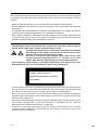
安全のために
当社の製品は安全に充分配慮して設計されています。しかし、操作や設置時にまちがっ
た取扱いをすると、火災や感電などにより死亡や大ケガなど人身事故につながることが
あり、危険です。また、機械の性能を落としてしまうこともあります。
これらの事故を未然に防ぐために、安全のための注意事項は必ず守ってください。操作
や設置、保守、点検、修理などを行う前に、この
「安全のために」
を必ずお読みください。
警告表示の意味
このマニュアルでは、次のような表示をしています。表示内容をよく理解してから本文
をお読みください。
警告
この表示の注意事項を守らないと、火災や感電などにより死亡や大ケガなど人身事故に
つながることがあります。
注意
この表示の注意事項を守らないと、感電やその他事故によりケガをしたり周辺の物品に
損害を与えることがあります。
警告
・ 表示された電源電圧以外での電圧で使用しないでください。火災や感電の原因となる
恐れがあります。
・ 濡れた手による取付作業はおやめください。感電の原因となる恐れがあります。
・ 本体を分解や改造をしないでください。ケガの恐れや、内部回路が破損することがあ
ります。
注意
・ 作業を行なう前には、装置の状況をよく確かめて作業の安全を確保してください。
・ 電源などの駆動源は必ず切って作業をしてください。火災や事故の原因となります。
・ 電源などを入れて動かす場合は、周辺機械や装置などに指を挟まれないように十分注
意してください。
BS77
(1)
Safety Precautions
Sony Manufacturing Systems Corporation products are designed in full consideration of
safety. However, improper handling during operation or installation is dangerous and may
lead to fire, electric shock or other accidents resulting in serious injury or death. In addition,
these actions may also worsen machine performance.
Therefore, be sure to observe the following safety precautions in order to prevent these types
of accidents, and to read these "Safety Precautions" before operating, installing, maintaining,
inspecting, repairing or otherwise working on this unit.
Warning indication meanings
The following indications are used throughout this manual, and their contents should be
understood before reading the text.
Warning
Failure to observe these precautions may lead to fire, electric shock or other accidents
resulting in serious injury or death.
Caution
Failure to observe these precautions may lead to electric shock or other accidents resulting in
injury or damage to surrounding objects.
Warning
• Do not use this unit with voltages other than the specified supply voltage as this may
result in fire or electric shock.
• Do not perform installation work with wet hands as this may result in electric shock.
• Do not disassemble or modify the unit as this may result in injury or damage the
internal circuits.
Caution
• Be sure to check the machine and device conditions to ensure work safety before
working on the machine.
• Be sure to cut off the power supply and other sources of drive power before working
on the machine. Failure to do so may result in fire or accidents.
• When turning on the power supply or other sources of drive power to operate the
machine, take care not to catch your fingers in peripheral machines and devices.
(2)
BS77
CAUTION
Use of controls or adjustments or perfomance of procedures other than those specified herein may result in
hazardous radiation exposure.
See Manual
DANGER
INVISIBLE LASER
RADIATION WHEN OPEN. AVOID
DIRECT EXPOSURE TO BEAM.
CERTIFICATION
PRODUCT COMPLIES WITH DHHS RULES 21
CFR SUBCHAPTER J APPLICABLE AT DATE
OF MANUFACTURE.
SONY MANUFACTURING SYSTEMS CORPORATION
1-10 KIYOKU-CHO, KUKI-SHI,
SAITAMA 346-0035 JAPAN
MANUFACTURED AT ISEHARA PLANT
SONY MANUFACTURING SYSTEMS CORPORATION
2-933-725-**
CAUTION
DO NOT REMOVE COVER REFER SERVICING TO
QUALIFIED PERSONNEL.
ATTENTION
NE PAS DEMONTER LE CAPOT. LAISSER REVISER
A PERSONNEL DIPLOMEE.
R
MADE IN JAPAN
LASERSCALE BS77
POWER
Ser.No. ******
Sony Manufacturing Systems Corporation
BS77
(3)
Sicherheitsmaßnahmen
Bei dem Entwurf von Sony Manufacturing Systems Corporation Produkten wird größter Wert
auf die Sicherheit gelegt. Unsachgemäße Handhabung während des Betriebs oder der
Installation ist jedoch gefährlich und kann zu Feuer, elektrischen Schlägen oder anderen
Unfällen führen, die schwere Verletzungen oder Tod zur Folge haben können. Darüber hinaus
kann falsche Anwendung die Leistung der Maschine verschlechtern.
Beachten Sie daher unbedingt die besonders hervorgehobenen Sicherheitshinweise in dieser
Bedienungsanleitung, um derartige Unfälle zu verhüten, und lesen Sie die folgenden
Sicherheitsmaßnahmen vor der Inbetriebnahme, Installation, Wartung, Inspektion oder
Reparatur dieses Gerätes oder der Durchführung anderer Arbeiten durch.
Bedeutung der Warnhinweise
Bei der Durchsicht dieses Handbuchs werden Sie auf die folgenden Hinweise und Symbole
stoßen. Machen Sie sich mit ihrer Bedeutung vertraut, bevor Sie den Text lesen.
Warnung
Eine Mißachtung dieser Hinweise kann zu Feuer, elektrischen Schlägen oder anderen
Unfällen führen, die schwere Verletzungen oder Tod zur Folge haben können.
Vorsicht
Eine Mißachtung dieser Hinweise kann zu elektrischen Schlägen oder anderen Unfällen führen,
die Verletzungen oder Sachbeschädigung der umliegenden Objekte zur Folge haben können.
Warnung
• Betreiben Sie dieses Gerät nur mit der vorgeschriebenen Versorgungsspannung, da
anderenfalls die Gefahr von Feuer oder elektrischen Schlägen besteht.
• Führen Sie Installationsarbeiten nicht mit nassen Händen aus, da hierbei die Gefahr
elektrischer Schläge besonders groß ist.
• Unterlassen Sie jeden Versuch, das Gerät zu zerlegen oder umzubauen, da dies zu
Verletzungen oder Beschädigung der internen Schaltungen führen kann.
Vorsicht
• Überprüfen Sie vor Arbeitsbeginn unbedingt den Zustand von Maschine und Vorrichtungen,
um die Arbeitssicherheit zu gewährleisten.
• Schalten Sie vor Arbeiten an der Maschine unbedingt die Stromzufuhr und andere
Antriebsstromquellen aus. Anderenfalls besteht Brand- oder Unfallgefahr.
• Achten Sie beim Einschalten der Stromversorgung usw. zum Betrieb der Maschine darauf,
daß Sie sich nicht die Finger in peripheren Maschinen und Vorrichtungen klemmen.
(4)
BS77
ACHTUNG
Die Betätigung von Bedien- und Einstellteilen bzw. die Ausführung von Verfahren, die nicht in dieser
Bedienungsanleitung beschrieben sind, können zu gefährlicher Strahlungsbelastung führen.
See Manual
DANGER
INVISIBLE LASER
RADIATION WHEN OPEN. AVOID
DIRECT EXPOSURE TO BEAM.
CERTIFICATION
PRODUCT COMPLIES WITH DHHS RULES 21
CFR SUBCHAPTER J APPLICABLE AT DATE
OF MANUFACTURE.
SONY MANUFACTURING SYSTEMS CORPORATION
1-10 KIYOKU-CHO, KUKI-SHI,
SAITAMA 346-0035 JAPAN
MANUFACTURED AT ISEHARA PLANT
SONY MANUFACTURING SYSTEMS CORPORATION
2-933-725-**
CAUTION
DO NOT REMOVE COVER REFER SERVICING TO
QUALIFIED PERSONNEL.
ATTENTION
NE PAS DEMONTER LE CAPOT. LAISSER REVISER
A PERSONNEL DIPLOMEE.
R
MADE IN JAPAN
LASERSCALE BS77
POWER
Ser.No. ******
Sony Manufacturing Systems Corporation
BS77
(5)
一般的注意事項
以下は当社製品を正しくお使いいただくための一般的注意事項です。個々の詳細な取扱上の注意
は,本取扱説明書に記述された諸事項および注意をうながしている説明事項に従い,正しくお使
いください。
. 始業または操作時には,当社製品の機能および性能が正常に作動していることを確認してから
ご使用ください。
. 当社製品が万一故障した場合,各種の損害を防止するための十分な保全対策を施してご使用く
ださい。
. 仕様に示された規格以外での使用または改造を施された製品については,機能および性能の保
証はできませんのでご留意ください。
. 当社製品を他の機器と組合せてご使用になる場合は,使用条件,環境等により,その機能およ
び性能が満足されない場合がありますので,十分ご検討の上ご使用ください。
使用上の注意事項
. スケールユニットに使用している半導体レーザの波長は可視帯域から外れた780 nm,最大出
力は3 mWです。
. スケールヘッドから出る光は目には見えませんが人体に有害ですので,検出
ヘッド部のカバーは絶対に取り外さないでください。
光が漏れる可能性がありますので,通電時にスケール挿入部分を覗き込まな
いでください。また,スケール以外の物を差し込むことは絶対に行なわない
でください。
. スケールには,それぞれ固有のスケールピッチの補正値が記入されたラベルが貼られていま
す。ご使用前に必ずこの値を接続するデテクタに設定してください。(3ページをご参照くださ
い。)
. スケールユニットのコネクタプラグには静電気保護用キャップが付いていますので,デテクタ
接続時まで取り外さないでください。
また,コネクタプラグの静電気保護キャップ取り外し後に,コネクタピンに触れないように特
に注意してください。故障の原因となります。
. スケールユニットのコネクタとデテクタのレセプタクルを完全に接続し,ネジで固定してから
電源スイッチをONにしてください。
また,電源をONしたままコネクタを抜き差ししないでください。
. ケーブルを強く引いたり,無理に曲げてのご使用は避けてください。{曲げ半径 50 mm (内側)
以上}
. 電源投入後10分位経過しますと,検出ヘッド部の温度が安定状態となります。その後にご使用
ください。
. 本品は精密測定器のため,過度の衝撃が加わらないよう取扱いには十分注意してください。ま
た,輸送するときは必ず製品購入時と同じ包装形態でお願いします。
BS77
(J) i
目次
1. 概要 ..................................................................................... 1
1-1.
1-2.
特長 ................................................................................................................. 1
各部の名称 ..................................................................................................... 1
2. 取付け上の注意事項 ............................................................ 2
2-1.
2-2.
2-3.
取付けにあたって ......................................................................................... 2
取付け時に準備するもの ............................................................................. 2
取付けの前に ................................................................................................. 3
2-3-1. 補正値について ............................................................................ 3
2-3-2. 補正値のセット方法 .................................................................... 3
3. 取付け・調整方法 ............................................................... 4
3-1.
3-2.
取付面の準備 ................................................................................................. 4
スケールの取付け ......................................................................................... 6
3-2-1. BS77-10N/NS, 30N/NS ............................................................... 6
3-2-2. BS77-70N/NS∼420N/NS ........................................................... 6
3-3. スライダの取付け .......................................................................................... 9
3-4. 信号調整 ........................................................................................................ 10
3-4-1. 信号調整準備 ............................................................................... 10
3-4-2. アジマス調整 ............................................................................... 11
3-5. 取付け・調整終了 ........................................................................................ 12
4. 仕様 ................................................................................... 13
5. 外形寸法図 ........................................................................ 14
ii (J)
BS77
1. 概要
1-1. 特長
■ マグネスケール並みの扱い易さと信頼性。
■ 光波干渉計 (レーザ測長器) 並みの高精度,高分解能。
■ 温度・気圧・空気の乱れに左右されない安定測長。
■ 内挿精度,繰返し精度,戻り誤差がいずれも1/100マイクロメートルオーダの超高精度測長。
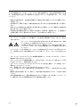
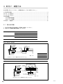
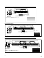
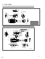
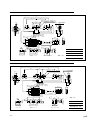
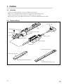
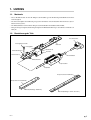
1-2. 各部の名称
コネクタプラグ
スケール
取付ネジ
基準
プレート
検出ヘッド部
スケール
クランプ
スライダ
スペーサ
接続ケーブル
ケーブルクランプ
中継アンプ
ヘッドケーブル
補正値ラベル
補正値ラベル
スケール
(有効長 10/30 mm)
スケール
(有効長 70 mm以上)
BS77
(J) 1
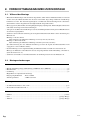
2. 取付け上の注意事項
2-1. 取付けにあたって
. スケ−ルと検出ヘッドは組合せて調整されています。複数個のスケールユニットを取扱われる
場合は,必ず同一梱包内の組合せでご使用ください。万一スケールと検出ヘッドの組合せが分
からなくなった場合は,付属の精度表に記載されている製造番号でご確認ください。
. 取付位置 (アッベ誤差) と周囲の環境 (温度, 湿度, 振動, 塵挨) について十分ご検討ください。
. ヘッドケーブルは動力線と同一ダクトに通さないでください。
. 機械可動部の最大移動長さはスケール最大可動長以下にしてください。
有効長10, 30 mmの場合
最大可動長 = 有効長 +2 mm (片側 1 mm)
有効長70 mm以上の場合
最大可動長 = 有効長 +10 mm (片側 5 mm)
(最大可動長を越えた場合はスケールユニットの信号が出力されず,エラーが発生しますので
ご注意ください。)
. スケールユニットは,その取付け後にスケール信号調整を必要とします。機械への取付けにあ
たって,調整するためのスペースを十分とれるよう考慮してください。
(4∼12ページをご参照ください。)
. ご使用前に必ずスケールの補正値を接続するデテクタにセットしてください。
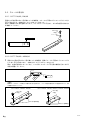
2-2. 取付け時に準備するもの
測定器
. てこ式ダイヤルゲージ ..................................................................................................................... 1台
(2/1000 mmまたは1/1000 mm目盛りのもの)
. ダイヤルゲージスタンド ................................................................................................................. 1台
. オシロスコープ ................................................................................................................................. 1台
2現象 X-Y表示可能なもの
入力感度
: DC 0.1 V/DIV
X-Y周波数帯域 : 1 MHz以上
工具
. 六角レンチ (呼び3, 2) ................................................................................................................... 各1本
. プラスドライバ (呼び1番) ............................................................................................................... 1本
その他
. 付属品 .................................................................................................................................................. 1式
. ガーゼ ................................................................................................................................................ 少量
. アルコール ....................................................................................................................................... 少量
2 (J)
BS77
2-3. 取付けの前に
2-3-1. 補正値について
スケールのホログラム格子ピッチPGは約0.55 umですが,検出信号ピッチPS は原理的にこの1/4
の約0.14 umです。この値はスケールごとに若干の違いがあります。そのため,正確な移動量を
得るためには各スケール固有のピッチ補正を加える必要があります。
補正値とは20 dC温度下でのスケールユニット固有の検出ピッチ
PS = 0.1379[|] [|] [|] [|] um
の下4桁を表します。
ご使用前に必ずスケールの補正値をデテクタにセットしてください。
20 dCと異なる温度環境でご使用になる場合
使用温度が20 dCと異なる場合には,次のように補正値の修正を行なうことにより,温度補正を
行なうことができます。使用温度が23 dCの場合の例を示します。
例) 補正値ラベルに示された補正値が[1] [2] [3] [4]の場合
0.1379 [1] [2] [3] [4] x {1 + (23_20) x (_0.7 x 10_6)} = 0.1379 [1] [2] [0] [5]
20 dCとの温度差
スケールの温度膨張係数 (13ページ参照)
温度補正後の補正値は[1] [2] [0] [5]となります。この値をセットしてください。
2-3-2. 補正値のセット方法
デテクタ (BDシリーズ) 取扱説明書の「補正値の設定」の項をご覧ください。
N
デテクタ (BDシリーズ) の補正値は出荷時オールゼロが設定されています。この状態ではアラームが出力されご使用に
なれません。必ずスケールの補正値を正しく設定してからご使用ください。
また,補正のないデテクタの場合は,分解能の計算が必要ですので各デテクタの取扱説明書をご覧ください。
BS77
(J) 3
3. 取付け・調整方法
次の手順で行なってください。(詳細は該当ページをご参照ください。)
3-1. 取付面の準備 ....................................................................................................................................... 4
3-2. スケールの取付け ............................................................................................................................... 6
3-3. スライダの取付け ............................................................................................................................... 9
3-4. 信号調整 ............................................................................................................................................. 10
3-4-1. 信号調整準備 ........................................................................................................................... 10
3-4-2. アジマス調整 ........................................................................................................................... 11
3-5. 取付け・調整終了 ............................................................................................................................. 12
3-1. 取付面の準備
1. 取付面の範囲 (図中斜線部) と面精度を確認してください。
2. 取付けネジ座標の精度を確認してください。
スケール取付面
粗さ (Rmax)
スライダ取付面
6.3S
平面度
0.01 mm以下
機械の走りに対する平行度
0.01 mm以下
粗さ (Rmax)
12.5S
スケール取付面に対する平行度
0.03 mm以下
BS77-10N/NS, 30N/NS
スケール取付面
(L)
Rmax=6.3S
16
8 ±0.1
0.01 M
0.01
10
3.5
4-M3 深6
スケール取付面
0.03 A
スライダ取付面
スライダ取付面
20.1 ±0.2
10.8
9.8 ±0.2
38 ±0.2
46
Rmax=12.5S
単位 : mm
注) Mはマシンガイド(機械の走り)を示します。
型名
L
BS77-10N/NS
21.5
BS77-30N/NS
31.5
BS77-70N/NS
100
88 ±0.3
25 ±0.2
0.03 A
スライダ取付面
スケール取付面
スライダ取付面
38 ±0.2
46
46.6 ±0.3
9.8 ±0.2
10.8
0.01 M
0.01
25 ±0.2
23
Rmax=6.3S
(7)
40
6-M4 深6
16 ±0.2
スケール取付面
2-M3 深6
Rmax=12.5S
単位 : mm
注) Mはマシンガイド(機械の走り)を示します。
4 (J)
BS77
BS77-120N/NS, 170N/NS, 220N/NS
L1
L2
25 ± 0.2
10.8
スケール取付面
0.03 A
38 ±0.2
スライダ取付面
スライダ取付面
46.6 ±0.3
9.8 ±0.2
25 ±0.2
23
0.01 M
0.01
25 ±0.2
(7)
8-M4 深6
Rmax=6.3S
L2
50 ±0.3
16 ±0.2
スケール取付面
単位 : mm
2-M3 深6
46
Rmax=12.5S
型名
注)Mはマシンガイド(機械の走り)を示します。
L1
L2
BS77-120N/NS 148
50
BS77-170N/NS 198
75
BS77-220N/NS 248
100
BS77-270N/NS, 320N/NS
L1
100
40
88 ±0.3
スケール取付面
25 ±0.2
25 ±0.2
25 ±0.2
スケール取付面
10.8
9.8 ±0.2
0.03 A
スライダ取付面
スライダ取付面
46.6 ±0.3
16 ±0.2
0.01 M
0.01
25 ±0.2
23
Rmax=6.3S
100
(7)
10-M4 深6
単位 : mm
2-M3 深6
38 ±0.2
型名
46
Rmax=12.5S
L1
BS77-270N/NS 298
BS77-320N/NS 348
注)Mはマシンガイド(機械の走り)を示します。
BS77-370N/NS, 420N/NS
L1
スケール取付面
25 ±0.2
L2
L2
50 ±0.3
25 ±0.2
25 ±0.2
L2
25 ±0.2
25 ±0.2
(7)
L2
12-M4 深6
スライダ取付面
Rmax=12.5S
注) Mはマシンガイド(機械の走り)を示します。
スライダ取付面
38 ±0.2
46
46.6 ±0.3
スケール取付面
0.03 A
BS77
16 ±0.2
9.8 ±0.2
10.8
0.01 M
0.01
23
Rmax=6.3S
単位 : mm
2-M3 深6
型名
L1
L2
BS77-370N/NS 398
75
BS77-420N/NS 448
100
(J) 5
3-2. スケールの取付け
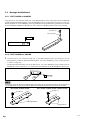
3-2-1. BS77-10N/NS, 30N/NS
用意された取付面にほこり等が無いことを確認後,スケールを下図のようにマシンガイドに対し
平行に取付けます。(締め付けトルク: 0.8 N・m = 8 kgf・cm)
図の一点鎖線で示す面が基準となります。ダイヤルゲージで平行出し,または取付面に突き当て
を準備してください。
M3 x 8
2本
ワッシャ
0.01
M
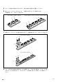
3-2-2. BS77-70N/NS∼420N/NS
1
用意された取付面にほこり等が無いことを確認後,基準プレートを下図のようにマシンガイ
ドに対し平行に取付けます。 (締め付けトルク 1.4 N・m = 14 kgf・cm)
図中,左側が基準穴となっています。てこ式ダイヤルゲージで平行度の確認を行ないながら
右側で調整してください。
基準
0.01
M
N
基準プレートはスケールを取付ける際の突き当て基準となり,スケール精度を再現する上で重要なものです。必ず
仕様通り取付けてください。
BS77-70N/NS, 270N/NS, 320N/NS
BS77-120N/NS, 170N/NS, 220N/NS, 370N/NS, 420N/NS
M4 x 8
2本
M4 x 8
2本
突き当て基準面
突き当て基準面
6 (J)
BS77
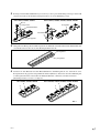
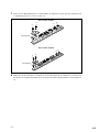
2
スケールクランプを図のように取付けネジを用い,がたがある程度 (仮締めから1∼2回転戻
す程度) にセットします。
BS77-70N/NS, 270N/NS, 320N/NS
BS77-120N/NS, 170N/NS, 220N/NS, 370N/NS, 420N/NS
M4 x 8
基準プレート
ワッシャ
スケールクランプ
スペーサ
基準プレート
3
スケールの取付面および突当面にほこり, 汚れが無いことを確認してください。汚れがある
場合はアルコールを含ませたガーゼで 拭き取ってください。
取付面
突当面
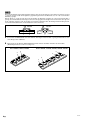
4
スケールをスケールクランプと取付面の間に挿入し,突き当て基準面に軽く押し当てます (注
意)。基準面に押し当てながら図に示すスケールクランプ (2個使いのものは左側,3個使いの
ものは中央のスケールクランプ) の取付ネジをA→B→A・・・の順序で交互に少しずつ締め付け
ていきます。(最終締付けトルク 1.4 N・m = 14 kgf・cm)
BS77-70N/NS, 270N/NS, 320N/NS
BS77-120N/NS, 170N/NS, 220N/NS, 370N/NS, 420N/NS
B
B
A
A
図1
N
スケールを基準面に突き当てるときは,下図左のように基準面に対向するスケール端面を指で軽く (9.8 N = 1 kgf 以下
の力) 押さえてください。下図右のようにスケールの中央部を押さえる (4.9 N = 0.5 kgf 以上の力) など,スケールに変
形を加えたまま固定しますと所定の精度を得ることができません。(以下の手順でもこの点に十分ご注意ください。万一
強い曲げ力が加わったと思われる場合は,スケールクランプを緩め再度正しく取付けてください。)
良
BS77
不可
(J) 7
5
スケールを熱的に安定化させるために,図1の状態で1時間以上放置してください。
6
残りのスケールクランプをA→B→A・・・・の順序で交互に少しずつ締め付けます。
(最終締付トルク 1.4 N・m = 14 kgf・cm)
BS77-70N/NS, 270N/NS, 320N/NS
BSS77-120N/NS, 170-N/NS, 220N/NS, 370N/NS, 420N/NS
B
B
A
A
B
A
7
両端にスケールクランプを同様に締め付けます。(最終締め付けトルク 1.4 N・m = 14 kgf・cm)
BS77-270N/NS, 320N/NS
B
A
B
A
スペーサ
BS77-370N/NS, 420N/NS
B
A
B
A
スペーサ
8
8 (J)
スケール面に油や塵挨の付着がないことを確認します。汚れがある場合は,アルコールを含
ませたガーゼで拭き取ります。このときスケールの表面に拭きムラが無いことを確認してく
ださい。
BS77
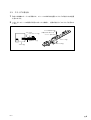
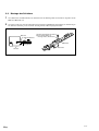
3-3. スライダの取付け
1
取付ける機械のテーブルを移動させ,スケールのほぼ中央位置にスライダの取付け中央位置
を合わせます。
2
スライダとスケールの隙間が均等であることを確認し,付属の取付ネジでスライダを仮止め
します。
スケール
スケールクランプ
基準プレート
スライダ
BS77
スライダ取付ネジ
(六角付ボルトM3 x 12)
ワッシャ (呼び 3)
スケール
スライダ
(J) 9
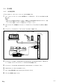
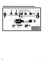
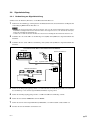
3-4. 信号調整
3-4-1. 信号調整準備
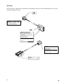
デテクタ (BDシリーズ) とスケールユニットBS77を接続します。
1
スケールユニットのヘッドコネクタ部保護キャップを取り外し,デテクタの HEAD INに接
続します。
N
. コネクタピンには絶対に手を触れないでください。静電気により内部の電気部品が壊れる恐れがあります。輸送
時などコネクタを接続しないときは,必ず保護キャップを取付けてください。
. ヘッドコネクタの着脱は,必ずデテクタの電源を切ってから行なってください。
2
デテクタのシグナル調整部にオシロスコープのCH1プローブをS (SIN) とG (GND) に接続し
ます。
3
オシロスコープのCH2プローブをC (COS) とG (GND) に接続します。
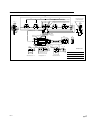
BS77とデテクタユニットBDシリーズの接続
デテクタ
BDシリーズ
オシロスコープ
CH1
CH2
S
C
G
CH1
シグナル調整部
詳細図
プローブ
SIG OUT
S
C
CH2
G
CHECK
ヘッドコネクタ
BS77 スケールユニット
HEAD IN
HEAD IN
SALM
LALM
REF
RESET
LASER SCALE
4
オシロスコープのCH1,CH2のINPUT COUPLINGスイッチをGNDに合わせ,信号がスク
リーン中央にくるようにオシロスコープのPOSITIONを調整します。
5
オシロスコープのCH1およびCH2のINPUT COUPLINGスイッチをDCにします。
6
TIME/DIVスイッチをX-Y MODEにします。
7
CH1,CH2の偏向感度 (VOLTS/DIV) を0.5 V/DIVにします。
8
デテクタの電源をONにします。
10 (J)
BS77
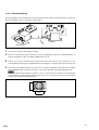
3-4-2. アジマス調整
下図に示したような方向をアジマス方向と呼ぶことにします。スライダの向きを調整すると,規
定値 (振幅1.6 V p-p) 以上の安定した出力信号を得ることができます。
アジマス方向
アジマス方向
1
スライダ取付ネジをゆるめます。
2
スライダを図のように回転させ,リサージュの振幅が最大となる場所をみつけます。
3
リサージュの振幅が最大となるスライダ位置で,スライダ取付ネジを2本交互に徐々に締め付
けます。(締付トルク0.8 N・m = 8 kgf・cm)
4
スケールを移動させて全長に渡りリサージュの振幅A, B (下図参照) が1.6 V p-p以上であるこ
とを確認します。
N
調整を繰返しても1.6 V p-pの出力が得られない場合は,スケールとスライダの取付面精度 (参照 4∼5ページ),お
よびスケール面上にゴミの付着がないか再度ご確認ください。
A
B
BS77
(J) 11
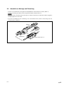
3-5. 取付け・調整終了
. ケーブルを付属のケーブルクランプと小ネジ (M4 x 8) で固定します。
. 中継アンプを付属のネジ (六角穴付ボルトM3 x 18) で固定します。
N
検出ヘッドと中継アンプは同電位にしてください。
所定の性能が得られない場合があります。
. 締付け部の安定化とスケール周辺の熱的安定化をはかるため,取付け後3時間程度放置してか
らご使用ください。
スケール
小ネジ
(M4 x 8)
ケーブルクランプ
12 (J)
六角穴付ボルト
M3 x 18
BS77
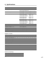
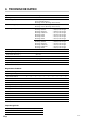
4. 仕様
項目
性能・機能
有効長
10, 30, 70, 120, 170, 220, 270, 320, 370, 420 mm
全長
48 mm (有効長10 mm)
68 mm (有効長30 mm)
有効長 +26 mm (有効長70∼420 mm)
最大可動長
有効長 +2 mm (有効長10, 30 mm)
有効長 +10 mm (有効長70∼420 mm)
精度 (20 dCにて)
NSタイプ
有効長 10/30 mm
70/120 mm
170/220 mm
270 mm
320 mm
370 mm
420 mm
± 0.03 um以下
± 0.08 um以下
± 0.15 um以下
± 0.20 um以下
± 0.34 um以下
± 0.39 um以下
± 0.44 um以下
Nタイプ
有効長 10/30 mm
70/120 mm
170/220 mm
270/370 mm
420 mm
± 0.06 um以下
± 0.20 um以下
± 0.35 um以下
± 0.50 um以下
± 0.65 um以下
もどり誤差
± 0.02 um
繰返し精度
± 0.01 um
温度係数
_0.7 x 10_6/dC
光源
半導体レーザ
検出方式
回析格子走査式
使用温度範囲
+10∼+30 dC (結露不可)
保存温度範囲
_10∼+50 dC
付属品
スケール有効長
10
30
70
120
170
220
270
320
370
420
取扱説明書
1
1
1
1
1
1
1
1
1
1
六角穴付ボルト (M3 x 8)
2
2
_
_
_
_
_
_
_
_
六角穴付ボルト (M3 x 12)
2
2
2
2
2
2
2
2
2
2
六角穴付ボルト (M3 x 18)
2
2
2
2
2
2
2
2
2
2
六角穴付ボルト (M4 x 8)
_
_
6
8
8
8
10
10
12
12
ワッシャ (呼び3)
4
4
2
2
2
2
2
2
2
2
ワッシャ (呼び4)
_
_
6
8
8
8
10
10
12
12
基準プレート
_
_
1
1
1
1
1
1
1
1
スペーサ
_
_
_
2
2
2
2
2
4
4
スケールクランプ
_
_
2
3
3
3
4
4
5
5
ケーブルクランプ
1
1
1
1
1
1
1
1
1
1
小ネジ (M4 x 8)
1
1
1
1
1
1
1
1
1
1
精度表
1
1
1
1
1
1
1
1
1
1
梱包内容
検出ヘッド (中継アンプと接続ケーブルを含む)
1
スケール
1
付属品一式
1
BS77
(J) 13
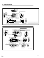
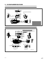
5. 外形寸法図
BS77-10N/NS, 30N/NS
9.8
14.5
スケール信号検出位置
L1
L2
6.6
4.6
2-Ø3.4
3
ケーブル長1000
64
高さ21
4.4
29
38
44
27.5
20.1
28.5
2.5 8
1
8
24.5
9.8
32
16
45.9
6
40.5
53
47
6
3.5
26.5
2-Ø3.6
ケーブル長3000
9.5
2-Ø3.5ザグリ深さ10
単位 : mm
型名
L1
L2
BS77-10N/NS
48
36
BS77-30N/NS
68
46
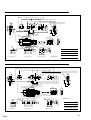
BS77-70N/NS
4-M4スケールクランプ取付ネジ
96
9.8
20
2
2-M4基準プレート スケール信号検出位置
取付ネジ
9.8
20
25
29
38
44
64
高さ21
3.5
26.5
2-Ø3.6
32
16
45.9
6
40.5
53
47
6
24.5
27.5
56
14
23
4.6
46.6
2.3
6.6
1
(7.5)
7 9
5
25
ケーブル長3000
25
88
15
Ø4
25
+0.05
0
25
0.4
5
5-Ø5
基準プレートt=2
14 (J)
1.4
21
12
16
42
60
14
9
基準穴
13.8
98
+0.05
Ø4 0
+0.05
0
2-Ø3.5ザグリ深さ10
4
9.5
38
スケールクランプ
単位 : mm
BS77
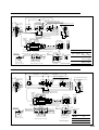
BS77-120N/NS, 170N/NS, 220N/NS
L1
L2
L2
6-M4 スケールクランプ取付ネジ
2-M4 基準プレート取付ネジ
60
9.8
50
2
25
スケール信号検出位置
9.8
25
ケーブル長1000 mm
29
38
44
64
高さ21
3.5
26.5
2-Ø3.6
32
45.9
6
16
40.5
53
47
6
24.5
27.5
6.6
4.6
56
14
23
46.6
2.3
1
(7.5)
7 9
5
25
+0.05
0
25
5
4
Ø4
0.4
1.4
型名
16
21
9
10
+0.05
Ø4 0
基準穴
14
2-Ø5
2-Ø3.5ザグリ深さ10
50
3-Ø5
25
+0.05
0
ケーブル長3000
9.5
42
60
12
スペーサt=2
基準プレートt=2
スケールクランプ
BS77-120N/NS 146
13.8
25
38
L1
38
単位 : mm
L2
50
BS77-170N/NS 196
75
BS77-220N/NS 246
100
BS77-270N/NS, 320N/NS
L1
100
40
100
8-M4 スケールクランプ取付ネジ
9.8
スケール信号検出位置
2-M4 基準プレート取付ネジ
2
25
25
9.8
25
29
38
44
64
高さ21
26.5
2-Ø3.6
32
3.5
16
45.9
6
40.5
53
47
6
24.5
27.5
56
23
6.6
4.6
46.6
14
2.3
1
(7.5)
7 9
5
25
ケーブル長3000
9.5
25
5-Ø5
+0.05
0
25
5
4
Ø4
1.4
16
21
基準穴
単位 : mm
0.4
25
38
42
60
38
スペーサt=2
基準プレートt=2
スケールクランプ
12
型名
13.8
25
88
15
9
10
+0.05
Ø4 0
14
2-Ø5
+0.05
0
2-Ø3.5ザグリ深さ10
98
L1
BS77-270N/NS 296
BS77-320N/NS 346
BS77
(J) 15
BS77-370N/NS, 420N/NS
L1
L2
9.8
L2
L2
2
25
10-M4 スケールクランプ取付ネジ
50
25
2-M4 基準プレート取付ネジ
25
スケール信号検出位置
9.8
25
ケーブル長1000 mm
29
38
44
64
高さ21
26.5
2-Ø3.6
32
3.5
16
45.9
6
40.5
53
47
6
24.5
27.5
6.6
4.6
56
14
23
46.6
2.3
1
(7.5)
7 9
5
25
L2
60
+0.05
0
25
5
14
42
60
0.4
1.4
単位 : mm
9
25
38
Ø4
12
13.8
3-Ø5
10
50
25
4
+0.05
Ø4 0
基準穴
16
21
2-Ø5
2-Ø3.5ザグリ深さ10
+0.05
0
ケーブル長3000
9.5
型名
L1
L2
38
スペーサt=2
16 (J)
基準プレートt=2
スケールクランプ
BS77-370N/NS 396
75
BS77-420N/NS 446
100
BS77
General Precautions
When using Sony Manufacturing Systems Corporation products, observe the following general
precautions along with those given specifically in this manual to ensure proper use of the
products.
. Before and during operations, be sure to check that our products function properly.
. Provide adequate safety measures to prevent damages in case our products should develop
malfunctions.
. Use outside indicated specifications or purposes and modification of our products will void any
warranty of the functions and performance as specified of our products.
. When using our products in combination with other equipment, the functions and performance
as noted in this manual may not be attained, depending upon operating environmental
conditions. Make full study of the compatibility in advance.
Operating Precautions
. The wavelength of the semiconductor laser used for this scale unit is 780 nm, which is
outside of the visible range, and the maximum output is 3 mW.
. The light transmitted from the scale head is detrimental to the human
body, though it is not visible to the human eye. For this reason, never
open the cover of the detector head assembly.
As there is a danger of light leakage, do not look into the scale
insertion openings while the power is on, and never try to insert
objects other than the scale through the scale insertion openings.
. Each scale bears a label showing a scale pitch compensation value proper to the scale.
Before operation, be sure to set the detector to this value. (See page 3.)
CLASS 1 LASER PRODUCT
LASERSCHUTZKLASSE 1 PRODUKT
TO EN 60825
. A static electricity proof cap is attached to the connector plug of the scale unit. Do not remove
this cap until you are ready to connect the detector. After removing the static electricity proof
cap, take care not to touch the connector pins as this might cause malfunctions.
. Be sure to make all connections of the scale unit connector and the detector receptacle by
fixing them with screws before switching the power on. Never insert or pull out the connector
when the power switch is on.
. Do not pull at the cable forcibly or bend it excessively. (Bending radius (inside): 50 mm or more)
. Use the BS77 approximately 10 minutes after power is supplied to the unit, when the
temperature of the detector head reaches a stable state.
. The BS77 is a precision measuring instrument. Handle it with extreme care so that no
excessive shock is applied to it. For transport, be sure to pack it in the same way as it was
packed at the time of purchase.
BS77
(E) i
Contents
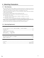
1. Outline ................................................................................ 1
1-1.
1-2.
Features ........................................................................................................... 1
Names of Parts ................................................................................................ 1
2. Mounting Precautions ...................................................... 2
2-1.
2-2.
2-3.
When Mounting .............................................................................................. 2
Mounting Requirements .................................................................................. 2
Before Mounting ............................................................................................. 3
2-3-1. Compensation Value ....................................................................... 3
2-3-2. Compensation Value Setting .......................................................... 3
3. Mounting and Adjustment ................................................ 4
3-1.
3-2.
3-3.
3-4.
3-5.
Mounting Surface Preparations ....................................................................... 4
Scale Mounting ............................................................................................... 6
3-2-1. BS77-10N/NS and 30N/NS ............................................................ 6
3-2-2. BS77-70N/NS to 420N/NS ............................................................ 6
Slider Mounting .............................................................................................. 9
Signal Adjustment ......................................................................................... 10
3-4-1. Signal Adjustment Preparations ................................................... 10
3-4-2. Azimuth Adjustment .................................................................... 11
Completion of Mounting and Adjustment ..................................................... 12
4. Spcifications .................................................................... 13
5. Dimensions ...................................................................... 14
ii (E)
BS77
1. Outline
1-1. Features
.
.
.
.
Simple use and high reliability common for all Magnescale products.
High accuracy and high resolution equivalent to a light wave interferometer system.
Stable measurement unaffected by temperature, disturbed air and air pressure.
Interpolation accuracy, repeatability and return error are all held to within 0.01 µm (0.39 µinch)
1-2. Names of Parts
Connector plug
Scale
Mounting screw
Reference plate
Detector head assembly
Scale clamp
Slider
Spacer
Connector cable
Cable clamp
Head amplifier
Head cable
Compensation value label
Compensation value label
Scale (measuring length: 10/30 mm)
Scale
(measuring length: 70 mm or more)
BS77
(E) 1
2. Mounting Precautions
2-1. When Mounting
. The scale and the detector head are adjusted to each other. If more than one scale unit is to be used, only
combine them with the detector heads provided in the same packing. If you do not know which scale and
detector head to use together, refer to the serial No. on the supplied accuracy chart.
. Consider the mounting position (Abbe error) and the environmental conditions (temperature, humidity,
vibration and dust) thoroughly.
. Do not lead the head cable through the same duct with the power cable.
. Set the maximum travel of the machine’s moving part shorter than that of the scale.
Measuring length = 10 or 30 mm:
Scale’s max. travel = measuring length +2 mm/0.08" (1 mm/0.04" per each side)
Measuring length = 70 mm or more:
Scale’s max. travel = measuring length +10 mm/0.39" (5 mm/0.20" per each side)
(If the scale’s max. travel is exceeded, the scale unit signals will not be output and an error will occur.)
. For the scale unit, scale signal adjustment is necessary after mounting. When mounting the scale to the
machine, make sure that there is enough space for the adjustment. (See pages 4 to 12.)
. Be sure to set the detector to the compensation value of the scale before operation.
2-2. Mounting Requirements
Measuring Instruments
. Lever type dial gauge (scale pitch: 2/1000 mm/0.00008" or 1/1000 mm/0.00004") ............................. (1)
. Dial gauge stand ..................................................................................................................................... (1)
. Oscilloscope ........................................................................................................................................... (1)
Capable of 2-quadrant X-Y display
Input sensitivity
: DC 0.1 V/DIV
X-Y frequency band : 1 MHz or more
Tools
. Hexagonal wrench 3 mm/0.118", 2 mm/0.079" ............................................................................ (1 each)
. Philips screwdriver No. 1 ....................................................................................................................... (1)
Miscellaneous
. Accessories ...................................................................................................................................... (1 set)
. Gauze ................................................................................................................................ (Small amount)
. Alcohol .............................................................................................................................. (Small amount)
2 (E)
BS77
2-3. Before Mounting
2-3-1. Compensation Value
The hologram grating pitch PG of the scale is approximately 0.55 µm/22 µinch, while the detector signal
pitch RS is theoretically 1/4 of this, that is 0.14 µm/5.5 µinch. This value differs slightly from scale to scale.
Therefore, it is necessary to additionally make the pitch compensation for each scale, in order to detect
precise displacements.
The lowest four digits of the detector signal pitch for each scale PS = 0.1379[|] [|] [|] [|] µm at 20 dC/68
dF show the compensation value.
Be sure to set the detector to the compensation value of the scale before operation.
When you operate the unit in an environment where the temperature is not 20 dC/68 dF
To operate the unit in an environment where the temperature is not 20 dC/68 dF, adjust the compensation
value as shown below to make a temperature adjustment. The following example shows the adjustment
method for an operating temperature of 23 dC/73 dF.
Example : The compensation value shown on the compensation value label is [1] [2] [3] [4].
0.1379 [1] [2] [3] [4] x {1 + (23_20) x (_0.7 x 10_6)} = 0.1379 [1] [2] [0] [5]
Temperature difference from 20 dC/68 dF
Coefficient of thermal expansion of the scale (See page 13.)
The compensation value after temperature adjustment will be [1] [2] [0] [5]. Set the detector to this value.
2-3-2. Compensation Value Setting
See the section “Compensation Value Setting” of the detector (BD series) instruction manual.
n
The compensation value of the detector (BD series) is set to all zeros at the time of shipment. In this state, the alarm
sounds and you cannot operate the unit. Be sure to set the detector to the correct compensation value of the scale before
operation.
In addition, the resolution must be calculated for detectors that do not perform compensation, so refer to the detector
instruction manual.
BS77
(E) 3
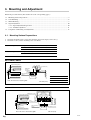
3. Mounting and Adjustment
Follow the procedure below. (For details refer to the corresponding pages.)
3-1.
3-2.
3-3.
3-4.
Mounting Surface Preparations ........................................................................................................... 4
Scale Mounting .................................................................................................................................... 6
Slider Mounting ................................................................................................................................... 9
Signal Adjustment ............................................................................................................................. 10
3-4-1. Signal Adjustment Preparations ............................................................................................. 10
3-4-2. Azimuth Adjustment .............................................................................................................. 11
3-5. Completion of Mounting and Adjustment ......................................................................................... 12
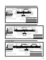
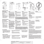
3-1. Mounting Surface Preparations
1. Check the mounting surface range (the shaded sections in the figure) and accuracy.
2. Check the accuracy of the mounting screw coordinates.
Scale mounting surface
Slider mounting surface
Roughness (Rmax)
6.3S/250 µinch
Flatness
0.01 mm/0.00039" or less
Parallelism to machine travel
0.01 mm/0.00039" or less
Roughness (Rmax)
12.5S/500 µinch
Parallelism to machine travel
0.03 mm/0.00118" or less
BS77-10N/NS, 30N/NS
(L)
Rmax=6.3S (250 µinch)
16 (0.63")
10
0.01(0.00039") M
0.01(0.00039")
10.8
(0.425")
4-M3 depth:
6 (0.24")
Slider mounting
surface
Slider mounting surface
Scale mounting surface
20.1 ±0.2
(0.791" ±0.008")
9.8 ±0.2 (0.386"±0.008")
0.03(0.00118") A
8 ±0.1 (0.315"±0.004")
3.5
(0.138")
38 ±0.2
(1.496" ±0.008")
46 (1.811")
Rmax=12.5S (500 µinch)
(0.394")
Scale mounting surface
Note: “M” refers to the machine guide.
Unit: mm (inch)
Model
L
BS77-10N/NS
21.5 (0.846")
BS77-30N/NS
31.5 (1.24")
Scale
mounting surface
0.03(0.00118") A
Slider mounting
surface
Slider mounting
surface
Rmax=12.5S (500 µinch)
Note: “M” refers to the machine guide.
4 (E)
16 ±0.2
9.8 ±0.2 (0.386"±0.008")
10.8 (0.425")
0.01(0.00039") M
0.01(0.00039")
23 (0.91")
Rmax=6.3S (250 µinch)
46.6 ±0.3
25 ±0.2
25 ±0.2
(0.984" ±0.008")(0.984" ±0.008")
(1.835" ±0.011")
40 (1.575")
6-M4 depth: 6 (0.24")
Scale mounting surface
(0.63" ±0.008")
100 (3.94")
88 ±0.3 (3.465" ±0.011")
(7 (0.2758"))
BS77-70N/NS
38 ±0.2
2-M3 depth: 6 (0.24")
(1.496" ±0.008")
46 (1.81")
Unit: mm (inch)
BS77
BS77-120N/NS, 170N/NS, 220N/NS
L1
25 ±0.2
(0.984" ±0.008")
Scale mounting
surface
0.03(0.00118") A
10.8
(0.425")
9.8 ±0.2 (0.386"±0.008")
Slider mounting surface
Slider mounting surface
Rmax=12.5S (500 µinch)
16 ±0.2
0.01(0.00039") M
0.01(0.00039")
38 ±0.2
(1.496" ±0.008")
46 (1.81")
2-M3 depth: 6 (0.24")
Model
Note: “M” refers to the machine guide.
Unit: mm (inch)
46.6 ±0.3
25 ±0.2
(0.984" ±0.008")
(1.835" ±0.011")
25 ±0.2
(0.984" ±0.008")
23 (0.91")
Rmax=6.3S (250 µinch)
L2
50 ±0.3 (1.969" ±0.011")
(7 (0.2758"))
8-M4 depth: 6 (0.24")
Scale mounting surface
(0.63" ±0.008")
L2
L1
L2
BS77-120N/NS 148 (5.83") 50 (1.969")
BS77-170N/NS 198 (7.8") 75 (2.953")
BS77-220N/NS 248 (9.76") 100 (3.94")
BS77-270N/NS, 320N/NS
L1
Scale mounting surface
0.03(0.00118") A
10.8
(0.425")
9.8 ±0.2 (0.386"±0.008")
Slider mounting surface
Slider mounting surface
Rmax=12.5S (500 µinch)
38 ±0.2
(1.496" ±0.008")
46 (1.81")
46.6 ±0.3
25 ±0.2
(0.984" ±0.008")
16 ±0.2
0.01(0.00039") M
0.01(0.00039")
25 ±0.2
25 ±0.2
(0.984" ±0.008") (0.984" ±0.008")
23 (0.91")
Rmax=6.3S (250 µinch)
(1.835" ±0.011")
25 ±0.2
(0.984" ±0.008")
Scale mounting surface
100 (3.94")
(7 (0.2758"))
10-M4 depth: 6 (0.24")
40 (1.575")
88 ±0.3 (3.465" ±0.011")
(0.63" ±0.008")
100 (3.94")
2-M3 depth: 6 (0.24")
Model
L1
BS77-270N/NS 298 (11.73")
Note: “M” refers to the machine guide.
Unit: mm (inch)
BS77-320N/NS 348 (13.7")
BS77-370N/NS, 420N/NS
L1
25 ±0.2
(0.984" ±0.008")
Scale mounting surface
0.03(0.00118") A
Slider mounting surface
Rmax=12.5S (500 µinch)
16 ±0.2
(0.63" ±0.008")
9.8 ±0.2 (0.386"±0.008")
Slider mounting surface
38 ±0.2
2-M3 depth: 6 (0.24")
(1.496" ±0.008")
46 (1.81")
Model
Note: “M” refers to the machine guide.
BS77
25 ±0.2
(0.984" ±0.008")
L1
(1.835" ±0.011")
25 ±0.2
(0.984" ±0.008")
10.8
(0.425")
0.01(0.00039") M
0.01(0.00039")
25 ±0.2
(0.984" ±0.008")
23 (0.91")
Rmax=6.3S (250 µinch)
L2
(7 (0.2758"))
Scale mounting surface
L2
L2
50 ±0.3 (1.969" ±0.011")
25 ±0.2
(0.984" ±0.008")
46.6 ±0.3
L2
12-M4 depth: 6 (0.24")
L2
BS77-370N/NS 398 (15.67") 75 (2.953")
Unit: mm (inch)
BS77-420N/NS 448 (17.64") 100 (3.94")
(E) 5
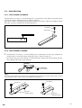
3-2. Scale Mounting
3-2-1. BS77-10N/NS and 30N/NS
Check that there is no dust, etc. on the mounting surface, and mount the scale parallel to the machine guide,
as shown in the figure. (Fastening torque : 0.8 N.m = 8 kgf.cm)
The reference surface is shown by the dotted and dashed line in the figure. Adjust the parallelism with the
dial gauge or prepare an abutment on the mounting surface.
Two M3 x 8
Plain washer
0.01 (0.00039) M
3-2-2. BS77-70N/NS to 420N/NS
1
Check that there is no dust, etc. on the mounting surface, and mount the reference plate parallel to the
machine guide, as shown in the figure. (Fastening torque: 1.4 N.m = 14 kgf.cm)
The reference hole is located on the left, as shown in the figure. Adjust at the right side while observing
the parallelism with the lever type dial gauge.
Reference
0.01 (0.00039) M
n
The scale is pressed against the reference plate for parallelism when mounting. The reference plate is vital to accurate
scale mounting. Be sure to mount it exactly as described in the specifications.
BS77-70N/NS, 270N/NS, 320N/NS
Two M4 x 8
Two M4 x 8
Reference
abutment surface
6 (E)
BS77-120N/NS, 170N/NS, 220N/NS, 370N/NS, 420N/NS
Reference
abutment surface
BS77
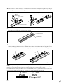
2
Attach the scale clamps loosely (1 or 2 full turns looser than the semi-tightened position) by using the
mounting screws, as shown in the figure.
BS77-70N/NS, 270N/NS, 320N/NS
M4 x 8
BS77-120N/NS, 170N/NS, 220N/NS, 370N/NS, 420N/NS
Reference plate
Plain washer
Scale clamp
Spacer
Reference plate
3
Check the mounting surface and the datum surface of the scale for dust and dirt. If the surfaces are dirty,
wipe them clean with gauze moistened with alcohol.
Mounting surface
Datum surface
4
Insert the scale between the scale clamp and the mounting surface while pressing the scale (datum
surface) lightly against the reference abutment surface (Note). Gradually and alternately tighten screws
A and B of the scale clamp indicated in the figure. (Final fastening torque: 1.4 N.0m = 14 kgf.cm)
BS77-70N/NS, 270N/NS, 320N/NS
BS77-120N/NS, 170N/NS, 220N/NS, 370N/NS, 420N/NS
B
B
A
A
Fig. 1
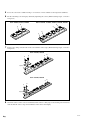
n
When pressing the scale against the reference surface, lightly press two points on the edge of the scale surface opposite
the reference surface with your fingers with a force of 9.8 N = 1 kgf or less as shown in Figure 1 below.
If the middle part of the scale is pressed with a force of 4.9 N = 0.5 kgf or more, as shown in Fig. 2 below or if the scale is
installed with deformation, the specified accuracy cannot be achieved. (This also applies to the following procedures. If it
appears that the scale has been bent by force, loosen the scale clamp and mount it again properly.)
CORRECT
BS77
WRONG
(E) 7
5
Leave the scale in the condition of Fig. 1 for one hour or more until the scale temperature stabilizes.
6
Fix the remaining scale clamps by alternately tightening the screws. (Final fastening torque: 1.4 N.m =
14 kgf.cm)
BS77-70N/NS, 270N/NS, 320N/NS
BSS77-120N/NS, 170-N/NS, 220N/NS, 370N/NS, 420N/NS
B
B
A
A
B
A
7
Fasten scale clamps on both ends of the scale with the same torque. (Final fastening torque: 1.4 N.m =
14 kgf.cm)
BS77-270N/NS, 320N/NS
B
A
B
A
Spacer
BS77-370N/NS, 420N/NS
B
A
B
A
Spacer
8
8 (E)
Check the surface of the scale for oil and dust. If the surface is dirty, wipe it clean with gauze moistened
with alcohol. Be sure to wipe off oil and dust on the surface thoroughly.
BS77
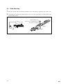
3-3. Slider Mounting
1
Move the machine table and adjust the mounting center of the slider to roughly the center of the scale.
2
Check that the gap between the slider and the scale is even, then semi-tighten the slider with the supplied mounting screws.
Scale
Scale clamp
Slider mounting screw
(M3 x 12 hex. socket-head cap screw)
Plain washer (nominal 3)
Scale
Reference plate
Slider
BS77
Slider
(E) 9
3-4. Signal Adjustment
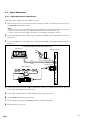
3-4-1. Signal Adjustment Preparations
Connect the detector (BD series) to the BS77 scale unit.
1
Remove the protective cap from the head connector of the scale unit, and connect the head connector to
the HEAD IN terminal of the detector.
n
. Do not touch the connector pins with your hands as this might damage the inner electronic parts by static electricity.
When the connector is not used, such as during transport, be sure to mount the protective cap.
. Be sure to switch off the power supply to the detector before attaching or removing the connector.
2
Connect the CH1 probe of the oscilloscope to S (SIN) and G (GND) of the signal adjustment section of
the detector.
3
Connect the CH2 probe of the oscilloscope to C (COS) and G (GND) of the signal adjustment section of
the detector.
Connecting the BS77 and a BD series detector unit
Oscilloscope
BD series detector
CH1
CH2
S
C
G
CH1
Signal adjustment
section - detailed view
SIG OUT
S
C
CH2
Probe
G
CHECK
Head connector
BS77 scale unit
HEAD IN
HEAD IN
SALM
LALM
REF
RESET
LASER SCALE
4
Set the input coupling switches of CH1 and CH2 of the oscilloscope to GND and adjust the oscilloscope
to locate the signal in the center of the screen.
5
Set the input coupling switches of CH1 and CH2 of the oscilloscope to DC.
6
Set the TIME/DIV switch to the X-Y mode.
7
Set the deviation sensitivity (VOLTS/DIV) of CH1 and CH2 to 0.5 V/DIV.
8
Turn the detector’s power on.
10 (E)
BS77
3-4-2. Azimuth Adjustment
A stable output signal of the specified value (amplitude: 1.6 V p-p) or higher can be obtained by adjusting
the slider azimuth direction.
Azimuth direction
Azimuth direction
1
Loosen the slider mounting screw.
2
Rotate the slider about the stopper as shown in the figure, until you find the point where the amplitude
of the Lissajous’ figure is at a maximum.
3
Alternately tighten the two slider mounting screws little by little at the slider position with the maximum amplitude of the Lissajous’ figure. (Fastening torque: 0.8 N.m = 8 kgf.cm)
4
Move the scale, and make sure that the amplitudes A and B of the Lissajous’ figure (see the figure
below) are 1.6 V p-p or greater over the entire length.
n
If output of 1.6 V p-p cannot be obtained even through repeated adjustment, recheck the mounting surface accuracy
of the scale and the slider (refer to pages 4 to 5), and check again that there is no dirt on the scale’s surface.
A
B
BS77
(E) 11
3-5. Completion of Mounting and Adjustment
. Secure the cable with the supplied cable clamp and small screw (M4 x 8).
. Secure the head amplifier with the supplied M3 x 18 hex. socket-head cap screw.
n
Set the detector and the head amplifier to the same electric potential. Otherwise, the specified performance may not be
attained.
. Leave the scale for about three hours after mounting for the tightened parts to thermally stabilize.
Scale
M4 x 8
small screw
Cable clamp
12 (E)
M3 x 18
hex. socket-head cap screw
BS77
4. Spcifications
Specification
Performance and functions
Measuring length mm (inch)
10, 30, 70, 120, 170, 220, 270, 320, 370, 420
Overall length mm (inch)
48 mm (measuring length 10 mm)
68 mm (measuring length 30 mm)
Measuring length +26 mm (measuring length 70 to 420 mm)
Max. travel mm (inch)
Measuring length +2 mm (measuring length 10 and 30 mm)
Measuring length +10 mm (measuring length 70 to 420 mm)
Scale accuracy (At 20 dC/68 dF)
NS type
Measuring length 10/30 mm
Measuring length 70/120 mm
Measuring length 170/220 mm
Measuring length 270 mm
Measuring length 320 mm
Measuring length 370 mm
Measuring length 420 mm
:
:
:
:
:
:
:
± 0.03 µm or less
± 0.08 µm or less
± 0.15 µm or less
± 0.20 µm or less
± 0.34 µm or less
± 0.39 µm or less
± 0.44 µm or less
N type
Measuring length 10/30 mm
Measuring length 70/120 mm
Measuring length 170/220 mm
Measuring length 270/370 mm
Measuring length 420 mm
:
:
:
:
:
± 0.06 µm or less
± 0.20 µm or less
± 0.35 µm or less
± 0.50 µm or less
± 0.65 µm or less
Return error µm (µinch)
± 0.02 (0.78)
Repeatability µm (µinch)
± 0.01 (0.39)
Temperature coefficient dC_1 (dF_1)
_0.7 x 10_6 (0.39 x 10_6)
Light source
Semiconductor laser
Detecting mode
Diffraction grating scanning
Operating temperature dC (dF)
+10 to +30 (+50 to +86) (no moisture condensation)
Storage temperature dC (dF)
_10 to +50 (+14 to +122)
Supplied accessories
Scale measuring length
10
30
70
120
170
220
270
320
370
420
Instruction manual
1
1
1
1
1
1
1
1
1
1
M3 x 8 hex. socket-head cap screw
2
2
—
—
—
—
—
—
—
—
M3 x 12 hex. socket-head cap screw
2
2
2
2
2
2
2
2
2
2
M3 x 18 hex. socket-head cap screw
2
2
2
2
2
2
2
2
2
2
M4 x 8 hex. socket-head cap screw
—
—
6
8
8
8
10
10
12
12
Plain washer (nominal 3)
4
4
2
2
2
2
2
2
2
2
Plain washer (nominal 4)
—
—
6
8
8
8
10
10
12
12
Reference plate
—
—
1
1
1
1
1
1
1
1
Spacer
—
—
_
2
2
2
2
2
4
4
Scale clamp
—
—
2
3
3
3
4
4
5
5
Cable clamp
1
1
1
1
1
1
1
1
1
1
M4 x 8 small screw
1
1
1
1
1
1
1
1
1
1
Accuracy chart
1
1
1
1
1
1
1
1
1
1
Contents of the package
Detector head (incl. Head amplifier and Connector cable)
1
Scale
1
1 set of supplied accessories
1
BS77
(E) 13
5. Dimensions
BS77-10N/NS, 30N/NS
9.8
(0.386")
14.5 (0.571")
Scale signal detection position
64 (2.52")
32 (1.26")
6 (0.236")
3.5
(0.138")
26.5 (1.043")
2-Ø3.6 (0.142")
(0.236")
Cable length 3000 (9.8 ft)
9.5 (0.38")
16 (0.63")
45.9 (1.81")
40.5 (1.59")
6
24.5 (0.965")
29(1.142")
38(1.496")
44(1.732")
53 (2.09")
47 (1.85")
27.5 (1.083")
2.5 (0.098")
Cable length 1000 (3.3 ft)
Height 21
(0.827")
2-Ø3.4 (0.134")
3 (0.118")
4.4 20.1
(0.173") (0.791")
28.5
(1.122")
L1
L2
8 (0.315")
1
(0.04")
8 (0.315")
9.8 (0.386")
6.6 (0.26")
4.6 (0.181")
2-Ø3.4 (0.134") countersunk depth: 5 (0.20")
Model
L1
L2
BS77-10N/NS 48 (1.89") 36 (1.417")
BS77-30N/NS 68 (2.677")46 (1.811")
Unit: mm (inch)
BS77-70N/NS
26.5 (1.043")
45.9 (1.81")
40.5 (1.59")
16 (0.63")
12 (0.47")
38 (1.5")
Reference plate t = 2 (0.08")
14 (E)
4
5
(0.197")
Scale clamp
0.4
(0.016") 1.4 (0.055")
21 (0.83")
14
25 (0.984")
16 (0.63")
42 (1.654")
60 (2.362")
+0.05
0
+0.002"
(0.157" 0
)
5-Ø5 (0.197")
9
)
Ø4
(0.551")
+0.002"
2-Ø3.4(0.134") countersunk depth: 5 (0.20")
98 (3.86")
88 (3.465")
25 15(0.591") 25
(0.984")
(0.984")
(0.354")
+0.05
Ø4 0 (0.157" 0
Reference hole
+0.05
0
+0.002"
(0.157" 0
)
Cable length 3000 (9.8 ft)
9.5 (0.38")
13.8 (0.54")
64 (2.52")
32 (1.26")
6 (0.236")
6
24.5 (0.965")
27.5 (1.083")
3.5
(0.138")
2-Ø3.6 (0.142")
(0.236")
53 (2.09")
47 (1.85")
Height 21
(0.827")
29(1.142")
38(1.496")
44(1.732")
9.8 (0.386")
56 (2.205")
4.6
(0.181")
5 (0.197")
23 14
(0.906") (0.551")
2.3
(0.0906")
6.6 (0.26")
46.6 (1.835")
20 (0.787") 20 (0.787")
25 (0.984") 25 (0.984")
1 (0.04")
(7.5(0.295"))
2-M4 reference
plate mounting screw Scale signal detection position
96 (3.78")
9.8
(0.386") 2 (0.079")
7 (0.276")
9 (0.354")
4-M4 scale clamp mounting screw
Unit: mm (inch)
BS77
BS77-120N/NS, 170N/NS, 220N/NS
L1
L2
L2
4.6
(0.181")
Cable length 1000 (3.3 ft)
3.5
(0.138")
2-Ø3.6 (0.142")
26.5 (1.043")
45.9 (1.81")
16 (0.63")
Cable length 3000 (9.8 ft)
42 (1.654")
60 (2.362")
38 (1.5")
Spacer t = 2 (0.08")
+0.05
0
(0.157"
5
(0.197")
+0.002"
0
)
12 (0.47")
38 (1.5")
Scale clamp
Reference plate t = 2 (0.08")
Model
L1
L2
4
25 (0.984")
0.4
(0.016") 1.4 (0.055")
21 (0.83")
25 (0.984")
9
10
(0.394")
Reference hole
Ø4
3-Ø5 (0.197")
+0.05
0
+0.002"
(0.157" 0
)
50 (1.969")
25 (0.984")
+0.002"
+0.05
)
0 (0.157" 0
(0.551")
Ø4
(0.354")
14
2-Ø5 (0.197")
2-Ø3.4(0.134") countersunk depth: 5 (0.20")
16 (0.63")
9.5 (0.38")
13.8 (0.54")
6
64 (2.52")
32 (1.26")
6 (0.236")
(0.236")
53 (2.09")
47 (1.85")
Height 21
(0.827")
29(1.142")
38(1.496")
44(1.732")
40.5 (1.59")
1 (0.04")
(7.5(0.295"))
7 (0.276")
2.3
(0.0906")
6.6 (0.26")
24.5 (0.965")
50 (1.969")
25 (0.984")
25 (0.984")
27.5 (1.083")
23 14
(0.906") (0.551")
46.6 (1.835") 5 (0.197")
56 (2.205")
9 (0.354")
6-M4 scale clamp mounting screw
2-M4 reference plate mounting screw
Scale signal detection position
25 (0.984")
9.8 (0.386")
60 (2.362")
9.8
(0.386") 2 (0.079")
BS77-120N/NS 146
50
(5.75") (1.969")
BS77-170N/NS 196
75
(7.72") (2.953")
BS77-220N/NS 246
100
(9.69") (3.94")
Unit: mm (inch)
BS77-270N/NS, 320N/NS
L1
40 (1.575")
100 (3.94")
8-M4 scale clamp mounting screw
25 (0.984") 25 (0.984")
25 (0.984")
14
23
4.6
(0.181")
29(1.142")
38(1.496")
44(1.732")
3.5
(0.138")
26.5 (1.043")
40.5 (1.59")
+0.05
0
+0.002"
(0.157" 0
)
4
5
(0.197")
12 (0.47")
38 (1.5")
Spacer t = 2 (0.08")
BS77
Reference plate t = 2 (0.08")
0.4
(0.016") 1.4 (0.055")
13.8 (0.54")
14
+0.002"
0
)
21 (0.83")
42 (1.654")
60 (2.362")
(0.157"
5-Ø5 (0.197")
25 (0.984")
+0.05
0
(0.551")
)
Ø4
16 (0.63")
38 (1.5")
+0.002"
98 (3.86")
88 (3.465")
25 15(0.591") 25
(0.984")
(0.984")
9
10
25 (0.984")
(0.394")
+0.05
Ø4 0 (0.157" 0
Reference hole
2-Ø3.4(0.134") countersunk depth: 5 (0.20")
(0.354")
2-Ø5 (0.197")
16 (0.63")
45.9 (1.81")
Cable length 3000 (9.8 ft)
9.5 (0.38")
9.8 (0.386")
2-Ø3.6 (0.142")
64 (2.52")
32 (1.26")
6 (0.236")
6
53 (2.09")
47 (1.85")
Height 21
(0.827")
(0.236")
1 (0.04")
(7.5(0.295"))
7 (0.276")
2.3
(0.0906")
6.6 (0.26")
Scale signal detection position
24.5 (0.965")
2-M4 reference plate mounting screw
25 (0.984")
27.5 (1.083")
9.8
(0.386") 2 (0.079")
(0.906") (0.551")
46.6 (1.835")
5 (0.197")
56 (2.205")
9 (0.354")
100 (3.94")
Model
L1
Scale clamp
BS77-270N/NS 296 (11.7")
Unit: mm (inch)
BS77-320N/NS 346 (13.7")
(E) 15
BS77-370N/NS, 420N/NS
L1
L2
25 (0.984")
25 (0.984")
4.6
(0.181")
Cable length 1000 (3.3 ft)
26.5 (1.043")
16 (0.63")
40.5 (1.59")
45.9 (1.81")
+0.002"
+0.05
)
0 (0.157" 0
25 (0.984")
38 (1.5")
Ø4
3-Ø5 (0.197")
9
(0.394")
10
Reference hole
50 (1.969")
25 (0.984")
42 (1.654")
60 (2.362")
(0.551")
Ø4
(0.354")
14
2-Ø5 (0.197")
25 (0.984")
+0.05
0
5
(0.197")
+0.002"
(0.157" 0
)
12 (0.47")
38 (1.5")
Spacer t = 2 (0.08")
Reference plate t = 2 (0.08")
4
+0.05
0
2-Ø3.4(0.134) countersunk depth: 5 (0.20")
0.4
(0.016") 1.4 (0.055")
13.8 (0.54")
Cable length 3000 (9.8 ft)
9.5 (0.38")
(0.157" +0.002"
0
)
6
53 (2.09")
47 (1.85")
(0.236")
64 (2.52")
32 (1.26")
6 (0.236")
Height 21 (0.827")
3.5
(0.138")
2-Ø3.6 (0.142")
16 (0.63")
29(1.142")
38(1.496")
44(1.732")
9.8 (0.386")
24.5 (0.965")
2-M4 reference plate mounting screw
56 (2.205")
25 (0.984")
10-M4 scale clamp mounting screw
27.5 (1.083")
25 (0.984")
50 (1.969")
25 (0.984")
23 (0.906") 14 (0.551")
46.6 (1.835")
5 (0.197")
60 (2.362")
Scale signal
detection position
L2
2.3
(0.0906")
6.6 (0.26")
1 (0.04")
(7.5(0.295"))
L2
21 (0.83")
9.8
(0.386") 2 (0.079")
7 (0.276")
9 (0.354")
L2
Scale clamp
Model
L1
L2
BS77-370N/NS 396 (15.6") 75 (2.953")
Unit: mm (inch)
16 (E)
BS77-420N/NS 446 (17.56") 100 (3.94")
BS77
Allgemeine Vorsichtsmaßregeln
Beachten Sie bei Verwendung unserer Produkte die folgenden allgemeinen Vorsichtsmaßregeln
neben den in diesem Handbuch speziell vermerkten Hinweisen, um korrekten Gebrauch der
Produkte zu gewährleisten.
. Vergewissern Sie sich vor und während des Betriebs, daß das Produkt einwandfrei funktioniert.
. Treffen Sie angemessene Sicherheitsmaßnahmen, um im Falle von Funktionsstörungen
Schäden zu vermeiden.
. Der Einsatz außerhalb der angegebenen Spezifikationen oder Zwecke und die Modifikation
unserer Produkte haben den Verfall der Garantie auf die angegebenen Funktionen und
Leistungen unserer Produkte zur Folge.
. Bei Verwendung unserer Produkte in Verbindung mit anderen Geräten werden je nach den
Betriebsumgebungsbedingungen die in dieser Anleitung angegebenen Funktionen und Leistungen
möglicherweise nicht erzielt. Daher sollte die Kompatibilität vorher gründlich überprüft werden.
Vorsichtsmaßregeln zum Betrieb
. Der Halbleiterlaser dieser Maßstabseinheit strahlt unsichtbares Laserlicht mit einer
Wellenlänge von 780 nm und einer maximalen Ausgangsleistung von 3 mW ab.
. Das vom Detektorkopf abgestrahlte unsichtbare Laserlicht ist
gesundheitsschädlich. Aus diesem Grund darf die Abdeckung der
Detektorkopfeinheit auf keinen Fall geöffnet werden.
Da die Gefahr von Leckstrahlung besteht, blicken Sie bei eingeschalteter
Stromversorgung nicht in die Maßstabs-Einschuböffnungen, und
versuchen Sie niemals, irgendwelche anderen Gegenstände außer dem
Maßstab in die Maßstabs-Einschuböffnungen einzuführen.
. An jedem Maßstab ist ein Aufkleber mit dem jeweiligen SkalenteilungsKompensationswert angebracht. Der Detektor muß vor dem Betrieb auf diesen Wert
eingestellt werden. (Siehe Seite 3.)
CLASS 1 LASER PRODUCT
LASERSCHUTZKLASSE 1 PRODUKT
TO EN 60825
. Der Stecker der Maßstabseinheit ist mit einer Kappe zum Schutz gegen statische Elektrizität
versehen. Entfernen Sie diese Kappe erst unmittelbar vor dem Anschluß des Detektors.
Vermeiden Sie eine Berührung der Steckerkontakte nach dem Abnehmen der Schutzkappe,
weil dies zu Funktionsstörungen führen könnte.
. Schalten Sie die Stromzufuhr erst ein, nachdem Sie alle Anschlüsse an Maßstabseinheit und
Detektor hergestellt und mit Schrauben gesichert haben. Der Stecker darf auf keinen Fall bei
eingeschalteter Stromzufuhr eingeführt oder herausgezogen werden.
. Unterlassen Sie gewaltsames Ziehen oder übermäßiges Biegen des Kabels. (Biegeradius
(innen): mindestens 50 mm)
. Warten Sie vor Benutzung der Maßstabseinheit BS77 ungefähr 10 Minuten nach dem
Einschalten der Stromzufuhr, bis sich die Temperatur des Detektorkopfes stabilisiert hat.
. Die Maßstabseinheit BS77 ist ein Präzisions-Meßinstrument. Behandeln Sie sie mit äußerster
Sorgfalt, damit sie keinen starken Erschütterungen ausgesetzt wird. Benutzen Sie zum
Transport die Originalverpackung der Maßstabseinheit.
BS77
(G) i
INHALT
1. UMRISS .............................................................................. 1
1-1.
1-2.
Merkmale ........................................................................................................ 1
Bezeichnung der Teile ..................................................................................... 1
2. VORSICHTSMASSNAHMEN ZUR MONTAGE .................. 2
2-1.
2-2.
2-3.
Während der Montage ..................................................................................... 2
Montageanforderungen ................................................................................... 2
Vor der Montage .............................................................................................. 3
2-3-1. Kompensationswert ........................................................................ 3
2-3-2. Kompensationswert-Einstellung .................................................... 3
3. MONTAGE UND EINSTELLUNGEN .................................. 4
3-1.
3-2.
3-3.
3-4.
3-5.
Vorbereitung der Montagefläche ..................................................................... 4
Montage des Maßstabs .................................................................................... 6
3-2-1. BS77-10N/NS und 30N/NS ........................................................... 6
3-2-2. BS77-70N/NS bis 420N/NS ........................................................... 6
Montage des Schiebers .................................................................................. 10
Signaleinstellung ........................................................................................... 11
3-4-1. Vorbereitung zur Signaleinstellung .............................................. 11
3-4-2. Azimuteinstellung ........................................................................ 12
Abschluß von Montage und Einstellung ....................................................... 13
4. TECHNISCHE DATEN ...................................................... 14
5. AUSSENABMESSUNGEN ............................................... 15
ii (G)
BS77
1. UMRISS
1-1. Merkmale
. Dieses Produkt besitzt die für alle Magnescale-Produkte typische Bedienungsfreundlichkeit und hohe
Zuverlässigkeit.
. Die hohe Genauigkeit und Auflösung entsprechen den Werten eines Lichtwellen-Interferometers (LaserInterferometersystem).
. Die Meßstabilität wird nicht durch Temperatur, Luftturbulenz und Luftdruck beeinflußt.
. Interpolationsgenauigkeit, Wiederholgenauigkeit und Rückstellfehler liegen ausnahmslos innerhalb von
0,01 µm.
1-2. Bezeichnung der Teile
Anschlußstecker
Befestigungsschraube
Maßstab
Bezugsplatte
Detektorkopf
Maßstabsklammer
Schieber
Abstandsstück
Anschlußkabel
Kabelklemme
Kopfverstärker
Kopfkabel
Kompensationswertaufkleber
Kompensationswertaufkleber
Maßstab (Meßlänge: 10/30 mm)
Maßstab (Meßlänge: 70 mm oder mehr)
BS77
(G) 1
2. VORSICHTSMASSNAHMEN ZUR MONTAGE
2-1. Während der Montage
. Maßstab und Detektorkopf sind aufeinander abgestimmt. Sollen mehrere Maßstabseinheiten verwendet
werden, darf jede Maßstabseinheit nur mit dem in derselben Verpackung enthaltenen Detektorkopf
kombiniert werden. Die Zusammengehörigkeit von Maßstab und Detektorkopf kann anhand der
Seriennummer auf der mitgelieferten Genauigkeitstabelle festgestellt werden.
. Montageposition (Abbe-Fehler) und Umgebungsbedingungen (Temperatur, Luftfeuchtigkeit, Vibrationen
und Staub) sind entsprechend zu berücksichtigen.
. Verlegen Sie das Kabel des Detektorkopfes oder das Verbindungskabel nicht im gleichen Kabelkanal wie
das Stromversorgungskabel.
. Stellen Sie den maximalen Verfahrweg des beweglichen Maschinenteils kürzer als den Verfahrweg des
Maßstabs ein.
Meßlänge = 10 oder 30 mm:
Max Verfahrweg des Maßstabs = Meßlänge +2 mm (1 mm auf jeder Seite)
Meßlänge = 70 mm oder mehr:
Max Verfahrweg des Maßstabs = Meßlänge +10 mm (5 mm auf jeder Seite)
(Bei Überschreitung des max. Maßstab-Verfahrwegs werden die Signale der Maßstabseinheit nicht
ausgegeben, so daß ein Fehler auftritt.)
. Nach der Montage ist eine Signaleinstellung der Maßstabseinheit erforderlich. Achten Sie bei der
Montage des Maßstabs an der Maschine darauf, daß genügend Platz für die Einstellung vorhanden ist.
(Siehe die Seiten 4 bis 13.)
. Stellen Sie den Detektor vor der Inbetriebnahme auf den Kompensationswert des Maßstabs ein.
2-2. Montageanforderungen
Meßinstrumente
. Meßuhr mit Hebelgestänge (Skalenteilung: 2/1000 mm oder 1/1000 mm) .......................................... (1)
. Meßuhrständer ....................................................................................................................................... (1)
. Oszilloskop ............................................................................................................................................ (1)
Möglichkeit zur 2-Quadrant-X-Y-Anzeige
Eingangsempfindlichkeit
: DC 0,1 V/DIV
X-Y-Frequenzband
: 1 MHz oder mehr
Werkzeuge
. Sechskant-Stiftschlüsse l3 mm, 2 mm ............................................................................................... (je 1)
. Kreuzschlitzschraubendreher Nr. 1 ........................................................................................................ (1)
Verschiedenes
. Zubehör .......................................................................................................................................... (1 Satz)
. Gaze ................................................................................................................................ (geringe Menge)
. Alkohol ........................................................................................................................... (geringe Menge)
2 (G)
BS77
2-3. Vor der Montage
2-3-1. Kompensationswert
Die Hologramm-Gitterteilung PG des Maßstabs beträgt ca. 0,55 µm, während die Detektorsignalteilung RS
theoretisch 1/4 dieses Wertes, d.h. 0,14 µm, beträgt. Dieser Wert ist je nach Maßstab geringfügig
unterschiedlich. Daher ist eine zusätzliche Teilungskompensation für jeden Maßstab notwendig, um genaue
Verschiebungen zu erkennen.
Die vier niedrigerwertigen Stellen der Detektorsignalteilung für jeden Maßstab PS = 0,1379[|] [|] [|] [|]
µm bei 20 dC stehen für den Kompensationswert.
Stellen Sie den Detektor vor der Inbetriebnahme auf den Kompensationswert des Maßstabs ein.
Wenn die Umgebungstemperatur von 20 dC abweicht
Soll die Einheit in einer Umgebung betrieben werden, deren Temperatur von 20 dC abweicht, muß der
Kompensationswert gemäß der nachstehenden Beschreibung eingestellt werden. Das folgende Beispiel zeigt
die Einstellung für eine Betriebstemperatur von 23 dC.
Beispiel : Der auf dem Kompensationswertaufkleber angegebene Kompensationswert beträgt
[1] [2] [3] [4].
0,1379 [1] [2] [3] [4] x {1 + (23_20) x (_0.7 x 10_6)} = 0,1379 [1] [2] [0] [5]
Temperaturdifferenz zu 20 dC
Wärmeausdehnungskoeffizient des Maßstabs (Siehe Seite 14.)
Der Kompensationswert nach der Temperaturanpassung beträgt [1] [2] [0] [5]. Stellen Sie den Detektor
auf diesen Wert ein.
2-3-2. Kompensationswert-Einstellung
Siehe den Abschnitt „Kompensationswert-Einstellung“ in der Gebrauchsanweisung des Detektors (BD-Serie).
[Hinweis]
Der Kompensationswert des Detektors (BD-Serie) wurde werkseitig auf Null eingestellt. In diesem Zustand ertönt der
Warnton, und die Einheit ist funktionsunfähig. Stellen Sie daher den Detektor vor der Inbetriebnahme auf den korrekten
Kompensationswert des Maßstabs ein.
Außerdem muß für Detektoren, die keine Kompensation durchführen, die Auflösung berechnet werden. Schlagen Sie
daher in der Gebrauchsanweisung nach.
BS77
(G) 3
3. MONTAGE UND EINSTELLUNGEN
Gehen Sie folgendermaßen vor. (Einzelheiten entnehmen Sie bitte den entsprechenden Seiten.)
3-1.
3-2.
3-3.
3-4.
Vorbereitung der Montagefläche ......................................................................................................... 4
Montage des Maßstabs ........................................................................................................................ 6
Montage des Schiebers ........................................................................................................................ 9
Signaleinstellung ............................................................................................................................... 11
3-4-1. Vorbereitung zur Signaleinstellung ........................................................................................ 11
3-4-2. Azimuteinstellung .................................................................................................................. 12
3-5. Abschluß von Montage und Einstellung ........................................................................................... 13
3-1. Vorbereitung der Montagefläche
1. Überprüfen Sie die Größe (schraffierte Teile in der Abbildung) und Genauigkeit der Montagefläche.
2. Überprüfen Sie die Genauigkeit der Befestigungsschrauben-Koordinaten.
Maßstab-Montagefläche
Schieber-Montagefläche
Rauheit (Rmax)
6,3S
Ebenheit
0,01 mm oder weniger
Parallelität zum Maschinen-Verfahrweg
0,01 mm oder weniger
Rauheit (Rmax)
12,5S
Parallelität zum Maschinen-Verfahrweg
0,03 mm oder weniger
BS77-10N/NS, 30N/NS
Maßstab-Montagefläche
(L)
Rmax=6,3S
16
8 ±0,1
0,01 M
0,01
10
3,5
4-M3 Tiefe: 6
SchieberMontagefläche
0,03 A
20,1 ±0,2
Maßstab-Montagefläche
10,8
9,8 ±0,2
38 ±0,2
46
Schieber-Montagefläche
Rmax=12,5S
Einheit: mm
Hinweis: „M“ bezieht sich auf die Maschinenführungsbahn.
Modell
L
BS77-10N/NS
21,5
BS77-30N/NS
31,5
BS77-70N/NS
100
88 ±0,3
40
6-M4 Tiefe: 6
25 ±0,2
Rmax=6,3S
0,03 A
Schieber-Montagefläche
Schieber-Montagefläche
38 ±0,2
46
46,6 ±0,3
16 ±0,2
Maßstab-Montagefläche
10,8
9,8 ±0,2
23
0,01 M
0,01
25 ±0,2
(7)
Maßstab-Montagefläche
2-M3 Tiefe: 6
Rmax=12,5S
Einheit: mm
Hinweis: „M“ bezieht sich auf die Maschinenführungsbahn.
4 (G)
BS77
BS77-120N/NS, 170N/NS, 220N/NS
L1
L2
8-M4 Tiefe: 6
25 ±0,2
Rmax=6,3S
25 ±0,2
25 ±0,2
10,8
Maßstab-Montagefläche
0,03 A
Schieber-Montagefläche
Schieber-Montagefläche
38 ±0,2
46.6 ±0,3
9,8 ±0,2
16 ±0,2
23
0,01 M
0,01
L2
50 ±0,3
(7)
Maßstab-Montagefläche
2-M3 Tiefe: 6
Einheit: mm
46
Rmax=12,5S
Modell
Hinweis: „M“ bezieht sich auf die Maschinenführungsbahn.
L1
L2
BS77-120N/NS 148
50
BS77-170N/NS 198
75
BS77-220N/NS 248
100
BS77-270N/NS, 320N/NS
L1
40
88 ±0,3
Maßstab-Montagefläche
25 ±0,2
25 ±0,2
25 ±0,2
Maßstab-Montagefläche
10,8
9,8 ±0,2
0,03 A
Einheit: mm
Schieber-Montagefläche
Schieber-Montagefläche
46,6 ±0,3
16 ±0,2
0,01 M
0,01
25 ±0,2
23
Rmax=6,3S
100
(7)
100
10-M4 Tiefe: 6
38 ±0,2
2-M3 Tiefe: 6
46
Modell
Rmax=12,5S
L1
BS77-270N/NS 298
BS77-320N/NS 348
Hinweis: „M“ bezieht sich auf die Maschinenführungsbahn.
BS77-370N/NS, 420N/NS
L1
25 ±0,2
L2
L2
50 ±0,3
25 ±0,2
25 ±0,2
L2
25 ±0,2
25 ±0,2
(7)
12-M4 Tiefe: 6
Maßstab-Montagefläche
L2
Maßstab-Montagefläche
Schieber-Montagefläche
10,8
0,03 A
Schieber-Montagefläche
Rmax=12,5S
Hinweis: „M“ bezieht sich auf die Maschinenführungsbahn.
BS77
38 ±0,2
46,6 ±0,3
9,8 ±0,2
16 ±0,2
0,01 M
0,01
23
Rmax=6,3S
Einheit: mm
2-M3 Tiefe: 6
46
Modell
L1
L2
BS77370N/NS
398
75
BS77420N/NS
448
100
(G) 5
3-2. Montage des Maßstabs
3-2-1. BS77-10N/NS und 30N/NS
Vergewissern Sie sich, daß kein Staub usw. an der Montagefläche haftet, und montieren Sie den Maßstab
parallel zur Maschinenführungsbahn, wie in der Abbildung gezeigt. (Anzugsmoment: 0,8 N.m = 8 kgf.cm)
Die Bezugsfläche ist in der Abbildung durch die punktierte und gestrichelte Linie gekennzeichnet. Stellen
Sie die Parallelität mit Hilfe der Meßuhr ein, oder versehen Sie die Montagefläche mit einem Anschlag.
Zwei M3 x 8
Unterlegscheibe
0,01
M
3-2-2. BS77-70N/NS bis 420N/NS
1
Vergewissern Sie sich, daß kein Staub usw. an der Montagefläche haftet, und montieren Sie die
Bezugszplatte parallel zur Maschinenführungsbahn, wie in der Abbildung gezeigt. (Anzugsmoment:
1,4 N.m = 14 kgf.cm)
Die Bezugsbohrung befindet sich auf der linken Seite, wie in der Abbildung gezeigt. Nehmen Sie die
Einstellung auf der rechten Seite vor, während Sie die Parallelität mit der Hebel-Meßuhr überwachen.
Bezugsbohrung
0,01
M
[Hinweis]
Der Maßstab wird bei der Montage zur Einhaltung der Parallelität gegen die Bezugsplatte gedrückt. Die Bezugsplatte ist
ausschlaggebend für eine genaue Montage des Maßstabs und muß daher genau nach Vorschrift montiert werden.
BS77-70N/NS, 270N/NS, 320N/NS
BS77-120N/NS, 170N/NS, 220N/NS, 370N/NS, 420N/NS
Zwei M4 x 8
Zwei M4 x 8
Stoßgrundfläche
Stoßgrundfläche
6 (G)
BS77
2
Befestigen Sie die Maßstabsklammern provisorisch (1 oder 2 ganze Umdrehungen weniger als die halb
angezogene Position) mit den Befestigungsschrauben, wie in der Abbildung gezeigt.
BS77-70N/NS, 270N/NS, 320N/NS
BS77-120N/NS, 170N/NS, 220N/NS, 370N/NS, 420N/NS
M4 x 8
Bezugsplatte
Unterlegscheibe
Maßstabsklammer
Abstandsstück
Bezugsplatte
3
Überprüfen Sie Montagefläche und Bezugsfläche des Maßstabs auf Staub und Schmutz. Falls die Flächen
verschmutzt sind, wischen Sie sie mit alkoholgetränkter Gaze ab.
Montagefläche
Bezugsfläche
4
Schieben Sie den Maßstab zwischen Maßstabsklammer und Montagefläche ein, während Sie seine
Bezugsfläche leicht gegen die Stoßgrundfläche drücken (Hinweis). Ziehen Sie die in der Abbildung mit
A und B gekennzeichneten Schrauben der Maßstabsklammer schrittweise und abwechselnd an.
(Endanzugsmoment: 1,4 N.m = 14 kgf.cm)
BS77-70N/NS, 270N/NS, 320N/NS
BS77-120N/NS, 170N/NS, 220N/NS, 370N/NS, 420N/NS
B
A
B
A
Abb.1
BS77
(G) 7
[Hinweis]
Wenn Sie den Maßstab gegen die Bezugsfläche drücken, üben Sie mit den Fingern an zwei Stellen einen Druck von 9,8 N
= 1 kgf oder weniger auf die der Bezugsfläche gegenüberliegende Kante des Maßstabs aus, wie in der nachstehenden
Abbildung 1 gezeigt.
Wird ein Druck von 4,9 N = 0,5 kgf oder mehr auf die Mitte des Maßstabs ausgeübt, wie in der nachstehenden Abb. 2
gezeigt, oder wird der Maßstab mit Verzug montiert, kann die angegebene Genauigkeit nicht erzielt werden. (Dies gilt auch
für die folgenden Verfahren. Falls der Verdacht auf Verzug des Maßstabs durch übermäßige Kraftanwendung besteht,
lösen Sie die Maßstabsklammer, um den Maßstab korrekt zu montieren.)
RICHTIG
FALSCH
5
Lassen Sie den Maßstab für etwa eine Stunde oder länger in dem in Abb. 1 gezeigten Zustand, bis sich
seine Temperatur stabilisiert.
6
Befestigen Sie die übrigen Maßstabsklammern durch abwechselndes Anziehen der Schrauben.
(Endanzugsmoment: 1,4 N.m = 14 kgf.cm)
BS77-70N/NS, 270N/NS, 320N/NS
BSS77-120N/NS, 170-N/NS, 220N/NS, 370N/NS, 420N/NS
B
B
A
A
B
A
8 (G)
BS77
7
Ziehen Sie die Maßstabsklammern an beiden Enden des Maßstabs mit dem gleichen Anzugsmoment
an. (Endanzugsmoment: 1,4 N.m = 14 kgf.cm)
BS77-270N/NS, 320N/NS
B
A
B
A
Abstandsstück
BS77-370N/NS, 420N/NS
B
A
B
A
Abstandsstück
8
Überprüfen Sie die Oberfläche des Maßstabs auf Öl und Staub. Falls die Oberfläche verschmutzt ist,
wischen Sie sie mit alkoholgetränkter Gaze ab. Wischen Sie Öl und Staub gründlich von der Oberfläche
ab.
BS77
(G) 9
3-3. Montage des Schiebers
1
Verschieben Sie den Maschinentisch, und richten Sie die Montagemitte des Schiebers ungefähr auf die
Mitte des Maßstabs aus.
2
Vergewissern Sie sich, daß der Abstand zwischen Schieber und Maßstab gleichmäßig ist, und befestigen
Sie dann den Schieber provisorisch mit den mitgelieferten Befestigungsschrauben.
Maßstab
Maßstabsklammer
Bezugsplatte
Schieber
10 (G)
Schieber-Befestigungsschraube
(Inbusschraube M3 x 12)
Unterlegscheibe (Nennmaß 3)
Maßstab
Schieber
BS77
3-4. Signaleinstellung
3-4-1. Vorbereitung zur Signaleinstellung
Schließen Sie den Detektor (BD-Serie) an die Maßstabseinheit BS77 an.
1
Nehmen Sie die Schutzkappe vom Kopfstecker der Maßstabseinheit ab, und schließen Sie den Kopfstecker
an den Eingang HEAD IN des Detektors an.
[Hinweis]
. Berühren Sie die Steckerkontakte nicht mit den Fingern, weil sonst die internen Elektronikteile durch statische
Elektrizität beschädigt werden können. Wenn der Stecker nicht angeschlossen ist, z.B. während des Transports,
bringen Sie unbedingt die Schutzkappe an.
. Schalten Sie vor dem Anschließen oder Abtrennen des Steckers unbedingt die Stromzufuhr des Detektors aus.
2
Verbinden Sie die Sonde CH1 des Oszilloskops mit S(SIN) und G(GND) des Signaleinstellteils des
Detektors.
3
Verbinden Sie die Sonde CH2 des Oszilloskops mit C(COS) und G(GND) des Signaleinstellteils des
Detektors.
Anschluß der Einheit BS77 an eine Detektoreinheit der BD-Serie
Oszilloskop
Detektor der BD-Serie
CH1
CH2
S
C
G
SIG OUT
CH1
Signaleinstellteil - Detailansicht
S
C
CH2
Sonde
G
CHECK
Kopfstecker
Maßstabseinheit BS77
HEAD IN
HEAD IN
SALM
LALM
REF
RESET
LASER SCALE
4
Stellen Sie die Eingangskopplungsschalter von CH1 und CH2 am Oszilloskop auf GND, und stellen Sie
das Oszilloskop so ein, daß das Signal in Bildschirmmitte angezeigt wird.
5
Stellen Sie die Eingangskopplungsschalter von CH1 und CH2 am Oszilloskop auf DC.
6
Stellen Sie den Schalter TIME/DIV auf X-Y MODE.
7
Stellen Sie die Deviationsempfindlichkeit (VOLTS/DIV) von CH1 und CH2 auf 0,5 V/DIV ein.
8
Schalten Sie die Stromzufuhr des Detektors ein.
BS77
(G) 11
3-4-2. Azimuteinstellung
Durch geringfügiges Verstellen der Schieberausrichtung kann ein stabiles Ausgangssignal des angegebenen
Wertes (Amplitude 1,6 Vs-s) oder höher erzielt werden.
Azimutrichtung
Azimutrichtung
1
Lösen Sie die Schieber-Befestigungsschraube.
2
Drehen Sie den Schieber um den Anschlag, wie in der Abbildung gezeigt, bis Sie den Punkt finden, an
dem die Amplitude der Lissajous-Figur ihr Maximum erreicht.
3
Ziehen Sie die zwei Schieber-Befestigungsschrauben abwechselnd und schrittweise in der
Schieberstellung mit der größten Amplitude der Lissajous-Figur an. (Anzugsmoment: 0,8 N.m = 8 kgf.cm)
4
Verschieben Sie den Maßstab und vergewissern Sie sich, daß die Amplituden A und B der Lissajous-Figur
(siehe Abbildung unten) einen Wert von 1,6 Vs-s oder größer über die gesamte Maßstabslänge haben.
[Hinweis]
Falls trotz wiederholter Einstellung keine Ausgabe von 1,6 Vs-s erzielt werden kann, überprüfen Sie die Genauigkeit
der Montagefläche von Maßstab und Schieber (siehe die Seiten 4 bis 5), und vergewissern Sie sich erneut, daß kein
Schmutz an der Oberfläche des Maßstabs haftet.
A
B
12 (G)
BS77
3-5. Abschluß von Montage und Einstellung
. Sichern Sie das Kabel mit der mitgelieferten Kabelklemme und der kleinen Schraube (M4 x 8).
. Sichern Sie den Kopfverstärker mit der mitgelieferten Inbusschraube M3 x 18.
[Hinweis]
Stellen Sie Detektor und Kopfverstärker auf die gleiche elektrische Spannung ein. Anderenfalls wird die angegebene
Leistung möglicherweise nicht erzielt.
. Lassen Sie den Maßstab nach der Montage etwa drei Stunden ruhen, damit sich die Temperatur der
montierten Teile stabilisiert.
Maßstab
Kleine Schraube
M4 x 8
Kabelklemme
BS77
Inbusschraube M3 x 18
(G) 13
4. TECHNISCHE DATEN
Spezifikation
Leistung und Funktionen
Meßlänge (mm)
10, 30, 70, 120, 170, 220, 270, 320, 370, 420
Gesamtlänge (mm)
48 mm (Meßlänge 10 mm)
68 mm (Meßlänge 30 mm)
Meßlänge +26 mm (Meßlänge 70 bis 420 mm)
Max Verfahrweg (mm)
Meßlänge +2 mm (Meßlänge 10 und 30 mm)
Meßlänge +10 mm (Meßlänge 70 bis 420 mm)
Maßstabsgenauigkeit (bei 20dC)
NS-Typ
Meßlänge 10/30 mm
Meßlänge 70/120 mm
Meßlänge 170/220 mm
Meßlänge 270 mm
Meßlänge 320 mm
Meßlänge 370 mm
Meßlänge 420 mm
:
:
:
:
:
:
:
± 0,03 µm oder weniger
± 0,08 µm oder weniger
± 0,15 µm oder weniger
± 0,20 µm oder weniger
± 0,34 µm oder weniger
± 0,39 µm oder weniger
± 0,44 µm oder weniger
N-Typ
Meßlänge 10/30 mm
Meßlänge 70/120 mm
Meßlänge 170/220 mm
Meßlänge 270/370 mm
Meßlänge 420 mm
:
:
:
:
:
± 0,06 µm oder weniger
± 0,20 µm oder weniger
± 0,35 µm oder weniger
± 0,50 µm oder weniger
± 0,65 µm oder weniger
± 0,02
Rückführungsfehler (µm)
± 0,01
Wiederholgenauigkeit (µm)
_1
Temperaturkoeffizient (dC )
_0,7 x 10_6
Lichtquelle
Halbleiterlaser
Erfassungsart
Beugungsgitterabtastung
Betriebstemperatur (dC)
+10 bis +30 (keine Kondensation)
Lagertemperatur (dC)
_10 bis +50
Mitgeliefertes Zubehör
Maßstab-Meßlänge
10
30
70
120
170
220
270
320
370
420
Bedienungsanleitung
1
1
1
1
1
1
1
1
1
1
Inbusschraube M3 x 8
2
2
—
—
—
—
—
—
—
—
Inbusschraube M3 x 12
2
2
2
2
2
2
2
2
2
2
Inbusschraube M3 x 18
2
2
2
2
2
2
2
2
2
2
Inbusschraube M4 x 8
—
—
6
8
8
8
10
10
12
12
Unterlegscheibe (Nennmaß 3)
4
4
2
2
2
2
2
2
2
2
Unterlegscheibe (Nennmaß 4)
—
—
6
8
8
8
10
10
12
12
Bezugsplatte
—
—
1
1
1
1
1
1
1
1
Abstandsstück
—
—
_
2
2
2
2
2
4
4
Maßstabsklammer
—
—
2
3
3
3
4
4
5
5
Kabelklemme
1
1
1
1
1
1
1
1
1
1
Kleine Schraube M4 x 8
1
1
1
1
1
1
1
1
1
1
Genauigkeitstabelle
1
1
1
1
1
1
1
1
1
1
Verpackungsinhalt
Detektorkopf (inkl. Kopfverstärker und Anschlußkabel)
1
Maßstab
1
1 Satz Standardzubehör
1
14 (G)
BS77
5. AUSSENABMESSUNGEN
BS77-10N/NS, 30N/NS
9,8
14,5
Erfassungsposition für Maßstabsignal
9,8
L1
L2
6,6
4,6
2-Ø3,4
3
64
Höhe 21
4,4
29
38
44
24,5
Kabellänge 1000
27,5
20,1
28,5
2,5
8
1
8
32
16
45,9
6
40,5
53
47
6
3,5
26,5
2-Ø3,6
Modell
L1
L2
BS77-10N/NS
48
36
BS77-30N/NS
68
46
Kabellänge 3000
2- Ø3,4 Senkungstiefe: 5
9,5
Einheit: mm
BS77-70N/NS
4-M4 Maßstabsklammer-Befestigungsschraube
96
9,8
20
2
2-M4 Bezugsplatten- Erfassungsposition für Maßstabsignal
Befestigungsschraube
9,8
20
25
29
38
44
64
Höhe 21
3,5
26,5
2-Ø3,6
32
45,9
6
16
40,5
53
47
6
24,5
27,5
56
14
23
4,6
46,6
2,3
6,6
1
(7,5)
7 9
5
25
Kabellänge 3000
25
88
15
+0,05
0
Ø4
25
25
0,4
5
1,4
5-Ø5
21
16
14
9
Bezugsbohrung
42
60
12
Bezugsplatte t = 2
Maßstabsklammer
13,8
+0,05
Ø4 0
+0,05
0
2- Ø3,4 Senkungstiefe: 5
98
4
9,5
38
Einheit: mm
BS77
(G) 15
BS77-120N/NS, 170N/NS, 220N/NS
L1
L2
L2
25
6-M4 Maßstabsklammer-Befestigungsschraube
2-M4 Bezugsplatten-Befestigungsschraube
Erfassungsposition für Maßstabsignal
9,8
25
29
38
44
2-Ø3,6
60
9,8
50
2
Kabellänge 1000
64
Höhe 21
3,5
26,5
32
45,9
6
16
40,5
53
47
6
24,5
27,5
6,6
4,6
56
14
23
46,6
2,3
1
(7,5)
7 9
5
25
Modell
L1
L2
50
BS77-170N/NS 196
75
Maßstabsklammer
BS77-220N/NS 246
100
13,8
BS77-120N/NS 146
12
Bezugsplatte t = 2
Abstandsstück t = 2
1,4
38
42
60
25
38
0,4
16
21
9
10
25
5
Ø4
3-Ø5
4
+0,05
0
50
25
+0,05
Ø4 0
Bezugsbohrung
14
2-Ø5
2-Ø3,4 Senkungstiefe: 5
+0,05
0
Kabellänge 3000
9,5
Einheit: mm
BS77-270N/NS, 320N/NS
L1
100
40
100
8-M4 Maßstabsklammer-Befestigungsschraube
9,8
Erfassungsposition für Maßstabsignal
2-M4 Bezugsplatten-Befestigungsschraube
2
25
25
9,8
25
29
38
44
64
Höhe 21
26,5
2-Ø3,6
32
3,5
16
45,9
6
40,5
53
47
6
24,5
27,5
56
23
6,6
4,6
46,6
14
2,3
1
(7,5)
7 9
5
25
Kabellänge 3000
9,5
5-Ø5
9
25
5
Einheit: mm
0,4
1,4
25
38
42
60
38
Abstandsstück t = 2
Bezugsplatte t = 2
Maßstabsklammer
12
Modell
13,8
25
16
21
+0,05
0
Ø4
14
25
88
15
10
Ø4 0
Bezugsbohrung
4
98
+0,05
2-Ø5
+0,05
0
2- Ø3,4 Senkungstiefe: 5
L1
BS77-270N/NS 296
BS77-320N/NS 346
16 (G)
BS77
BS77-370N/NS, 420N/NS
L1
L2
9,8
L2
L2
2
25
10-M4 Maßstabsklammer-Befestigungsschraube
50
25
2-M4 Bezugsplatten-Befestigungsschraube
25
Erfassungsposition
für Maßstabsignal
9,8
25
Kabellänge 1000
29
38
44
64
Höhe 21
26,5
2-Ø3,6
32
3,5
16
45,9
6
40,5
53
47
6
24,5
27,5
6,6
4,6
56
14
23
46,6
2,3
1
(7,5)
7 9
5
25
L2
60
25
5
12
38
Abstandsstück t = 2
BS77
Bezugsplatte t = 2
1,4
Einheit: mm
14
42
60
0,4
9
25
38
+0,05
0
Ø4
Maßstabsklammer
13,8
3-Ø5
4
50
25
16
21
+0,05
Ø4 0
Bezugsbohrung
10
2-Ø5
2-Ø3,4 Senkungstiefe: 5
+0,05
0
Kabellänge 3000
9,5
Modell
L1
L2
BS77-370N/NS 396
75
BS77-420N/NS 446
100
(G) 17
このマニュアルに記載されている事柄の著作権は当社にあ
り、説明内容は機器購入者の使用を目的としています。
したがって、当社の許可なしに無断で複写したり、説明内
容(操作、保守など)と異なる目的で本マニュアルを使用
することを禁止します。
The material contained in this manual consists of
information that is the property of Sony Manufacturing
Systems Corporation and is intended solely for use by
the purchasers of the equipment described in this
manual.
Sony Manufacturing Systems Corporation expressly
prohibits the duplication of any portion of this manual
or the use thereof for any purpose other than the
operation or maintenance of the equipment described
in this manual without the express written permission
of Sony Manufacturing Systems Corporation.
Le matériel contenu dans ce manuel consiste en
informations qui sont la propriété de Sony
Manufacturing Systems Corporation et sont destinées
exclusivement à l'usage des acquéreurs de
l'équipement décrit dans ce manuel.
Sony Manufacturing Systems Corporation interdit
formellement la copie de quelque partie que ce soit de
ce manuel ou son emploi pour tout autre but que des
opérations ou entretiens de l'équipement à moins
d'une permission écrite de Sony Manufacturing
Systems Corporation.
Die in dieser Anleitung enthaltenen Informationen
sind Eigentum von Sony Manufacturing Systems
Corporation und sind ausschließlich für den Gebrauch
durch den Käufer der in dieser Anleitung
beschriebenen Ausrüstung bestimmt.
Sony Manufacturing Systems Corporation untersagt
ausdrücklich die Vervielfältigung jeglicher Teile dieser
Anleitung oder den Gebrauch derselben für
irgendeinen anderen Zweck als die Bedienung oder
Wartung der in dieser Anleitung beschriebenen
Ausrüstung ohne ausdrückliche schriftliche Erlaubnis
von Sony Manufacturing Systems Corporation.
保 証 書
保証規定
お フリガナ
様
お 名
前
客
ご 〒
様 住
所
保期
証間
電話
1 保証の範囲
1 取扱説明書、本体添付ラベル等の注意書に従った正
- -
常な使用状態で、保証期間内に故障した場合は、無
償修理いたします。
2 本書に基づく保証は、本商品の修理に限定するもの
お買上げ日
年
月
日
本 体
1
年 とし、それ以外についての保証はいたしかねます。
2 保証期間内でも、次の場合は有償修理となります。
1 火災、地震、水害、落雷およびその他天災地変によ
る故障。
型
名
2 使用上の誤りおよび不当な修理や改造による故障。
BS77
3 消耗品および付属品の交換。
4 本書の提示が無い場合。
5 本書にお買い上げ日、お客様名、販売店名等の記入
お買上げ店住所・店名
が無い場合。(ただし、納品書や工事完了報告書が
ある場合には、その限りではありません。)
3 離島、遠隔地への出張修理および持込修理品の出張修理
については、出張に要する実費を別途申し受けます。
電話
- -
印
本書はお買上げ日から保証期間中に故障が発生した場
合には、右記保証規定内容により無償修理を行うこと
をお約束するものです。
4 本書は日本国内においてのみ有効です。
5 本書の再発行はいたしませんので、紛失しないよう大切
に保管してください。
商品についてのお問い合わせ
ソニーマニュファクチュアリングシステムズ株式会社
コールセンター 〒259-1146 神奈川県伊勢原市鈴川45
TEL: 0120-55-7973
計測機器営業部
名古屋
大阪
サービス課
TEL: (0463) 92-7971
TEL: (052) 778-3181
TEL: (06) 6305-3101
TEL: (0463) 92-2132 〒259-1146
〒465-0095
〒532-0011
〒259-1146
神奈川県伊勢原市鈴川45
愛知県名古屋市名東区高社2-171
大阪府大阪市淀川区西中島2-14-6 新大阪第2ドイビル
神奈川県伊勢原市鈴川45 FAX: (0463) 92-7978
FAX: (052) 778-4147
FAX: (06) 6304-6586
FAX: (0463) 92-3090
サービス代行店
北海道地区:
東北、関東、甲信越地区:
東海、北陸地区:
近畿、中国、四国地区:
九州地区:
札幌
東京
横浜
岐阜
愛知
大阪
広島
福岡
(株)札幌トランジスタ
(有)保田電機
(株)ファーストビデオ
カトー商事(株)
(有)カメテック
(有)宮下電機サービス
(株)三田電子
三伸エンジニアリング(株)
TEL: (011) 631-3401
TEL: (0424) 92-9191
TEL: (045) 582-8649
TEL: (0583) 83-6234
TEL: (0568) 72-1435
TEL: (06) 6724-7005
TEL: (082) 831-5261
TEL: (092) 963-1296
Sony Manufacturing Systems Corporation
Isehara Plant
45 Suzukawa, Isehara-shi, Kanagawa 259-1146 Japan
TEL: +81 (463) 92-7971
FAX: +81 (463) 92-7978
TEL: (949) 770-8400
FAX: (949) 770-8408
TEL: (0711) 5858-777
FAX: (0711) 580715
Sony Precision Technology America, Inc.
20381 Hermana Circle, Lake Forest, CA 92630, U.S.A.
Sony Precision Technology Europe GmbH
Heinrich-Hertz-Strasse 1 , 70327 Stuttgart, Germany
http://www.sonysms.co.jp/
ソニーマニュファクチュアリングシステムズ株式会社
Sony Manufacturing Systems Corporation
〒346-0035 埼玉県久喜市清久町1-10
1-10 Kiyoku-cho, Kuki-shi, Saitama 346-0035 Japan
BS77
3-865-965-04
2004.4
Printed in Japan
©1999 Sony Manufacturing Systems Corporation
このマニュアルは再生紙を使用しています。