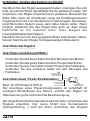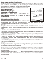
1
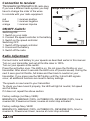
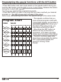
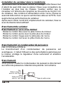
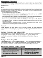
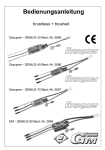
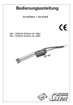
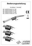
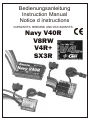
Bedienungsanleitung
Instruction Manual
Notice d instructions
VORWÄRTS, BREMSE UND RÜCKWÄRTS:
Navy V40R
V8RW
V4R+
SX3R
Herzlichen Glückwunsch zum Kauf Ihres Digital
Fahrtenreglers. Mit diesem Regler setzt Dipl.-Ing. (FH)
Ralf Helbing die Reihe seiner erfolgreichen Fahrtenregler
fort, mit denen schon Welt- und Europameisterschaften,
sowie nationale und internationale Titel gewonnen
wurden.
Wichtiger Hinweis:
Bitte lesen Sie diese Anleitung vor Gebrauch Ihres neuen
Fahrtenreglers sorgfältig durch. Nur so nutzen Sie das gesamte
Potential Ihres Reglers und vermeiden Fehler bei der Bedienung.
Beschreibung:
Die Fahrtenregler sind nur mit den modernsten Bauteilen
bestückt. Besonderer Wert wird hierbei auf Funktionalität,
Lebensdauer, Stand der Technik und Design gelegt. Die
Regler sind bereits mit den extrem hochwertigen SMD-FETs
ausgestattet. Diese FETs sind außerordentlich klein und
verlustarm.
Die von unserem Team ständig weiter entwickelte Software
garantiert in erster Linie präzise Einstellungen, hier
insbesondere Nullpunktjustierungen: Es kann keinerlei
mechanische Abweichungen geben, da alles digital
gespeichert und gesteuert wird. Das einfache ‘ProgrammierSystem’ ermöglicht Ihnen das Einstellen des Reglers
innerhalb von Sekunden ohne überflüssige Zusatzmittel wie
Chips, Programmiergerät oder dergleichen.
2
Gebrauchsanleitung
Englisch Derections
11
Notice d´instructions
21
Inhaltsverzeichnis
Installation / Einbau des Reglers
Anschluss des Reglers
Einstellen auf den Sender
Rückwärtsfunktion bei ..R - Reglern
Zusatzfunktionen
Technische Daten
Anschluss eines FET-Servos
Hinweise
Warnhinweise
Garantie
4
4-5
5
6
7-8
8
9
9
10
30
3
Installation / Einbau des Reglers ins Modell
Nachdem Sie den Regler ausgepackt haben, überlegen Sie sich
13
bitte, an welcher Stelle des Modells Sie ihn platzieren wollen. Wir
empfehlen, den Regler möglichst tief zu platzieren. Beachten Sie
dabei bitte, dass der Empfänger sowie die Empfängerantenne
möglichst mehr als 3 cm Abstand zum Fahrtenregler, den dicken,
stromführenden Kabeln sowie dem Akku haben sollte. Wenn
möglich, platzieren Sie den Regler bitte auch so, dass etwas
Fahrtwind an ihn kommen kann. Dies steigert die
Leistungsfähigkeit des Reglers.
Nachdem Sie sich für eine geeignete Stelle entschieden haben,
fixieren Sie bitte den Regler mit doppelseitigem Klebeband.
Anschluss des Reglers
Anschluss von Akku und Motor:
Verbinden Sie das blaue Kabel mit dem Minuspol des Motors
Verbinden Sie das gelbe Kabel mit dem Pluspol des Motors
Verbinden Sie das rote Kabel mit dem Pluspol des Fahrakkus
Verbinden Sie das schwarze Kabel mit dem Minuspol des
Plus
Fahrakkus
Den langen Draht
mit dem Akku +
Kabel verbinden
Anschluss eines Power-Kondensators:
Minus
Den kurzen Draht
mit dem Akku Kabel verbinden
Kennzeichnung
des Minuspols
Best.-Nr. 91539 oder 91539.G
Der Anschluss eines Power-Kondensators ist vorteilhaft. Er
verringert Störeinflüsse des Motors, schützt den Regler vor
Überspannung und verbessert die Beschleunigung.
Der lange Draht des Kondensators wird am Akku+ Anschluss des
Reglers angelötet. Der kurze Draht des Kondensators
(Kennzeichnung -) wird am Akku- Anschluss des Reglers
4
Anschluss an den Empfänger
Ihr Regler ist werkseitig mit einem JR-Stecker bestückt. Erkundigen Sie
sich bei Ihrem Fachhändler, ob Ihr Empfänger mit diesem Stecksystem
kompatibel ist, da sonst der Empfänger und das
BEC des Fahrtenreglers zerstört werden kann.
Tausch des Steckers oder Polung
ROT = Empfänger +
Widerhaken
BRAUN = Empfänger wegdrücken
und rausziehen
ORANGE = Impulsleitung
Stecken Sie den Stecker des
Danach
Widerhaken
Einbaubeispiel
wieder etwas
Empfängerkabels in Kanal 2 Ihres
zurückbiegen
Empfängers.
Einstellen auf den Sender
Anschließend Kabel
in den neuen
Stecker einführen
Nach dem ersten richtigen Einstecken und nach dem Einschalten ist der Regler
eingeschaltet und hat eine Grundeinstellung. Um den Regler auf Ihre
Fernsteuerung einzustellen, gehen Sie wie folgt vor:
Hinweis:
Bei jedem Tastendruck leuchtet die LED kurz auf, damit Sie wissen, dass die
Taste erkannt wurde. Während der Einstellung auf den Sender läuft der Motor
nicht.
- Drücken Sie kurz die Taste “SET”
- Der Regler ermittelt nun automatisch den Nullpunkt und die LED leuchtet. Nach
etwa zwei Sek. erlischt die LED.
- Gehen Sie nun innerhalb ca. 3 Sek. auf die Knüppelstellungen Vollgas, danach
Vollbremse/Vollrückwärts.
- Wenn Sie nun die ‘SET’ Taste drücken, bis die 3 kurzen LED Blinkzeichen
erscheinen, werden alle Zusatzfunktionen auf die Werkseinstellungen
zurückgesetzt.
- Der Einstellvorgang ist beendet, wenn 3 kurze LED Blinkzeichen das Ende des
Set-Programms anzeigen.
Fertig!
Ihr Regler ist nun schon eingestellt. Bei richtiger Einstellung leuchtet die LED nun
bei Vollgas , Nullpunkt und Vollbremse!
Werkseinstellung (außer NavyV40R): BRKMIN 0%, BRKMAX 100%, AUTOBRK
0%, REVERSE 100%, Zeit bis Rückwärts: 98, Powerkurve: linear, Rückwärts bei
Motorstillstand
Werkseinstellung Navy V40R:
BRKMIN 0%, BRKMAX 100%, AUTOBRK
0%, REVERSE 50%, Zeit bis Rückwärts: 4, Powerkurve: linear, Rückwärts bei
Motorstillstand
5
Beachten Sie bitte immer folgende Reihenfolge:
Einschalten:
Ausschalten:
1. Fernsteuerung einschalten
2. Regler einstecken
3. Regler einschalten
1. Regler ausschalten
2. Regler ausstecken
3. Fernsteuerung ausschalten
Rückwärtsfunktion bei ...R Reglern
Diese Fahrtenregler haben sowohl eine voll proportionale
Bremse als auch einen voll proportionalen Rückwärtsgang.
Es gibt verschiedene Möglichkeiten den Rückwärtsgang zu
aktivieren:
1. Um rückwärts fahren zu müssen Sie zuerst den Gashebel auf
die Position “Vollbremse” und dann zurück zur Neutralstellung
bringen. Der Rückwärtsgang ist nun eingelegt. Nun können Sie
proportional rückwärts fahren.
2. Um rückwärts fahren zu können muss das Fahrzeug
annähernd stehen und der Gashebel auf Neutral stehen. Nun
können Sie proportional rückwärts fahren.
(Rückwärts bei Motorstillstand)
3. Nach der eingestellten Zeit wird die Bremse für die
Rückwärtsfahrt umgeschaltet. (Zeit bis rückwärts: 0 - ca. 5 s)
Die Möglichkeit 1 lässt sich mit Möglichkeit 2 und/oder 3
kombinieren.
Siehe Programmierung Programm #5 und #6 auf den folgenden
Seiten.
Wichtiger Hinweis:
Bitte achten Sie darauf, dass Sie bei Verwendung eines
Rückwärtsreglers keine Schottky-Diode an den Motor
anschließen! Der Regler wird sonst zerstört, wenn Sie rückwärts
6
Zusatzfunktionen:
Programmnummern der über den Taster einstellbaren Funktionen:
Programmnummer
#1
#2
#3
#4
#5
#6
Programm
BRKMIN
BRKMAX
AUTOBRK
REVERSE
Zeit bis rückwärts
Powerkurve, Rückwärts bei Motorstillstand
#1: Minimale Bremse BRAKE MIN
Die Minimale Bremswirkung ist die, die unmittelbar nach dem Neutralpunkt ansteht.
Beispiel:
Wenn Sie die min. Bremse auf 30% einstellen, dann stehen beim Betätigen der Bremse sofort 30% Bremse
an. Der Bremsbereich des Hebels ist somit zwischen 30% und BREMSE MAX aufgeteilt und damit sensibler.
Die minimale Bremse ist zwischen 0% und 100% einstellbar. (0% ab Werk) (sinnvolle Werte: 0-50%)
#2: Maximale Bremse BRAKE MAX
Die maximale Bremswirkung ist die, die bei Vollbremse ansteht. Mit dieser
Überbremsen/Blockieren der Räder bei Vollbremse verhindern.
Die maximale Bremse ist zwischen 0% und 100% einstellbar. (100% ab Werk)
Tip: Die meisten Fahrer fahren die Maximale Bremse bei ca. 80%.
Funktion lässt sich ein
#3: Automatikbremse AUTOBRAKE
Die Automatikbremse ist von 0-100% einstellbar und wirkt bereits bei Neutralstellung des Gashebels. Sie ist
unabhängig von der minimalen und maximalen Bremswirkung einstellbar und erlaubt daher ein engeres
Kurvenfahren..
(0% ab Werk) (sinnvolle Werte: 0-30%)
#4: Maximale Rückwärtsfahrt REVERSE
Die maximale Rückwärtsfahrt ist von 0-100% getrennt von der Bremse einstellbar. Dadurch wird ein
vorbildgetreues Rückwärtsfahren erlaubt. Bei Booten kann ein Abtauchen des Bootes durch Verringerung
der maximalen Rückwärtsfahrt auf ca. 50% vermieden werden.
(100% ab Werk, bei Navy V40R 50% ab Werk) (sinnvolle Werte: 30-100%)
#5: Zeit bis rückwärts
Die Zeitverzögerung für die Rückwärtsfahrt kann unabhängig von den anderen Rückwärtsgangfunktionen
eingestellt werden.
0 = keine Zeitverzögerung (besonders für Trailmodelle in Zusammenhang mit 100% Automatikbremse)
1...9 = Zeitverzögerung ca. 0,5-5s
10 = der Rückwärtsgang wird nicht von der Zeitverzögerung aktiviert
#6: Powerkurve, Rückwärts bei Motorstillstand akt./deakt.
Im Programm 6 kann die Powerkurve, Gaskurve für das Regelverhalten im Halbgasbereich eingestellt
werden.
Linear = linear proportional
Soft
= ähnlich wie exponential - , besonders für Off-Road und rutschigen Untergrund
Hart
= ähnlich wie exponential+, besonders für Stock-Rennen
Weiterhin kann die Funktion der Rückwärtsgangaktivierung im Nullpunkt bei Motorstillstand aktiviert oder
deaktiviert werden. Rückwärts bei Motorstillstand akt. Kurve
deaktiviert. Kurve
Wertetabelle:
0
linear
4
linear
1
soft
5
soft
2
hart
6
hart
3
hart
7
hart
7
Programmieren der Zusatzfunktionen mit dem Taster
- Regler aus - Sender einschalten
- SET Taste drücken und gedrückt halten und gleichzeitig den Regler
einschalten, bis die LED 3 x kurz blinkt.
- während der oben genannten Blinkzeichen Taste loslassen
… Sie befinden sich nun im Programmmodus, Sie haben nun ca. je 3sek.
Zeit um das gewünschte Programm auszuwählen, ansonsten wechselt das
Programm nach ca. 3sek. in den Wertemodus.
Programmübersicht
PROG
WERTE
0-1-2-3-4-5-6-7-8-9-10
#1
BRKMIN
0
10
20
30
40
50
60
70
80
90 100
#2
BRKMAX
0
10
20
30
40
50
60
70
80
90 100
#3
AUTOBRK
0
10
20
30
40
50
60
70
80
90 100
REVERSE
0
10
20
30
40
50
60
70
80
90 100
#5
Zeit bis R
0
10
20
30
40
50
60
70
80
90 OO
-
-
#4
#6
POWERCURVE
Rückwärts bei
Motorstillstand
Lin.. Soft Hart Hart Lin. Soft Hart Hart
akt. akt. akt. akt. De- De- de- Deakt. akt. akt. akt.
-
- Drücken Sie dazu gemäß unten
stehender Tabelle die SET Taste
so oft, bis Sie das gewünschte
Programm erreicht haben. Bei
jeder Erhöhung des Programms
leuchtet die LED.
- Nach dem letzten Tastendruck
bestätigt der Regler nach ca. 3s
das Erreichen des Programms
mit 3 kurzen Blinkzeichen.
- Gleich danach zeigen 3 weitere
Blinkzeichen der LED das
Erreichen des Wertemodus an.
Sie können nun die Taste (Werte
in der Tabelle) so oft drücken, bis
der gewünschte Wert eingestellt
ist. Bei jeder Erhöhung des
Wertes leuchtet die LED.
- Der Regler bestätigt wiederum
mit 3 kurzen Blinkzeichen und
kehrt zum Fahrmodus zurück.
- Fertig!
Technische Daten:
Navy V40R
V8RW SX3R V4R+
Betriebsspannung:
R(DSon) in Ohm bei 25°C
Strom kurzzeitig 10s
Dauerstrom*
Windungen bei GM-Motoren
BEC Spg./Strom max. 10s
4,8-16,8V
2x0,001
120A
40A/60A wasserg.
>=10T
5,5V/3A
4,8-12V 4,8-12V 4,8-12V
2x0,0007 2x0,003 2x0,002
120A
60A
60A
60A
20A
32A
>=8T
>=18T
>=15T
5,5V/3A 5,5V/2A 5,5V/3A
*Der Dauerstrom bezieht sich auf Akkus mit max. 3600mAh.
8
Anschluss eines FET-Servos
Bei Verwendung eines FET-Servo mit zusätzlicher
Spannungsversorgung, schließen Sie das blaue FET-Servo
Kabel an Akku-Plus an. Oftmals wird eine Spule benötigt.
Lesen Sie dazu die Hinweise des Servo - Herstellers.
Hinweise:
FBei unzureichender Kühlluftzufuhr kann es durch den
Temperatursensor zu einer Abschaltung des Reglers kommen.
Das Fahrzeug bleibt jedoch jederzeit voll lenkbar. Sobald der
Regler wieder ausreichend abgekühlt ist, können Sie die Fahrt
fortsetzen.
Tip: Kühlkörper Best.-Nr. 2844.1 bzw 2853.1 verwenden. Dazu
entfernen Sie den Aufkleber an der Stelle, wo Sie den Kühlkörper
festkleben und kleben den Kühlkörper mit dem beiliegendem
Befestigungsmaterial auf das Kühlblech des Reglers. Beim Navy
V40R kann mit 4mm Messingrohren einfach eine
Wasserkühlung eingebaut werden..
-Achten Sie darauf, dass ihr Motor korrekt mit 2 Kondensatoren
(100nF) entstört ist.
-Achtung: Verpolen Sie niemals den Regler und schließen Sie
niemals einen Fahrakku direkt an den Motor an, solange der
Regler angeschlossen ist! In diesem Fall übernehmen wir keine
Garantie! Bringen Sie daher bitte Ihre Stecker so an, dass ein
Verpolen des Reglers ausgeschlossen ist.
9
Warnhinweise:
- Lassen Sie Ihr RC-Modell niemals unbeaufsichtigt, solange ein Akku
angesteckt ist. Im Falle eines Defektes, könnte dies Feuer am Modell oder
seiner Umgebung verursachen.
- Der Fahrtenregler oder andere elektronische Komponenten dürfen niemals
mit Wasser in Berührung kommen. Der Fahrtenregler ist vor Staub, Schmutz,
Feuchtigkeit, Vibration und anderen Fremdteilen zu schützen.
- Solange der Motor an den Regler angeschlossen ist, dürfen Sie niemals den
Motor mit einem separaten Akku laufen lassen. Dies zerstört den Regler und führt
zum Verlust der Garantie.
- Verpolen Sie Ihren Regler nicht. Benutzen Sie verpolsichere Stecksysteme.
Vermeiden Sie Kurzschlüsse und blockierende Motoren.
- Alle Kabel und Verbindungen sollen gut isoliert sein. Kurzschlüsse können
zur Zerstörung Ihres Reglers führen.
- Nicht für Kinder unter 14Jahren, kein Spielzeug!
- Die GM-Regler sind ausschließlich für den Einsatz in Batterie- bzw.
Akkubetriebenen, funkferngesteuerten Modellen vorgesehen, ein
anderweitiger Betrieb ist nicht zulässig.
- Motoren, Getriebe, Schiffs- oder Luftschrauben sind gefährliche
Gegenstände. Halten Sie sich daher niemals neben oder vor dem
Gefährdungsbereich des Antriebes auf!
Technische Defekte mechanischer oder elektronischer Teile können zum
unverhofften Anlaufen des Motors und herumfliegenden Teilen führen, die
erhebliche Verletzungen verursachen können.
- Führen Sie immer zuerst einen Reichweitetest am Boden durch (halten Sie
dabei Ihr Modell fest), bevor Ihr Modell zum Einsatz kommt.
- Es dürfen keinerlei Veränderungen am Regler durchgeführt werden, es sei
denn, diese sind in der Anleitung beschrieben.
- Haftungsausschluss: Sowohl die Einhaltung der Montage- und
Bedienungsanleitung, als auch die Bedingungen und Methoden bei
Installation, Betrieb, Verwendung und Wartung des Fahrtenreglers können von
der Fa. Graupner nicht überwacht werden. Daher übernimmt die Fa. Graupner
keinerlei Haftung für Verluste, Schäden oder Kosten, die sich aus fehlerhafter
Verwendung und Betrieb ergeben, oder in irgendeiner Weise damit
zusammenhängen.
- Es dürfen nur von uns empfohlene Komponenten und Zubehörteile
verwendet werden. Verwenden Sie nur zueinander passende, Original
GRAUPNER-Steckverbindungen und Zubehörteile.
- Vergewissern Sie sich vor jeder Inbetriebnahme bevor Sie den Fahrtenregler
einstecken, dass: Ihr Sender als einziger auf der Frequenz Ihres Empfängers
sendet und Ihr Sender eingeschaltet ist und der Gashebel auf der Position
STOP steht.
10
Operating instructions
Notice d´instructions
29
Gebrauchsanleitung
2
Content
Installing the speed controller
Connecting the speed controller
Matching the controller to the transmitter
Reverse function ...R speed controllers
Additional functions
Specification
Warnings
Warranty
13
13-14
14
15
16-17
18
18-19
30
11
Congratulations on your choice of a digital speed
controller. It is designed by our technical engineer, Ralf
Helbing, and continues his series of highly successful
speed controllers, which have already been used to win
World and European championships, and many national
and international titles.
Important:
Please read through these instructions carefully before you
use your new speed controller. Only in this way can you exploit
its full potential, and avoid errors in operating it.
Description:
The speed controllers are built using only the newest
components, with particular emphasis on functionality,
durability, and state-of-the-art technology and circuit design.
The controllers are equipped with the newest SMD-FETS of
extremely high quality. These FETs are exceptionally
compact and internal losses are ultra-low.
The controller software is subject to constant development
by our team, and provides supreme accuracy, especially
concerning zero point settings: there can be no mechanical
variations of any kind, since everything is stored and
controlled digitally. The easy programming system allows
you to set up the controller in seconds, with no need for
superfluous items such as chips, programmers or similar.
We confident that you will have hours of pleasure and
success with your new controller.
12
Installing the speed controller in the model
Once you have unpacked the controller, please consider the optimum
location for it in the model. We recommend that you install it as low in the
chassis as possible. Please note that the receiver and receiver aerial
should be at least 3 cm from the speed controller, the heavy high-current
cables and the battery, and preferably even further away than that. If
possible, position the controller in such a way that some air can flow over
the FETs, as this increases its general performance potential.
When you have decided on a suitable position, fix the controller in place
using double-sided foam tape.
Connecting the speed controller
Connecting the battery and motor
·
·
·
·
Connect the blue wire to the negative (-) motor terminal
Connect the yellow wire to the positive (+) motor terminal
Connect the red wire to the positive (+) battery terminal
Connect the black wire to the negative (-) battery terminal
Connecting a power capacitor
Order No.: 91539 or 91539.G
This capacitor gives you some advantages. This power capacitor can
solve an interference problem under certain conditions. It also
protects your speed controller from over voltage peaks and gives you
more power. The power capacitor is exactly tailored to the electrotechnical specification of our controllers, and this is the only type you
should use! You could ruin your controller by using a different type.
Positive
+
Connect the long
pin to the battery + wire
Negative terminal
identification mark
Negative
Connect the short
pin to the battery - wire
13
Connection to receiver
The speedos are fitted with a JR radio plug.
If you use a different radio system you may
have to change the order of the wires
to coincide with your radio equipment.
red
brown
orange
Change order of wires
1
= receiver positive
= receiver negative
= receiver impulse
2
ON/OFF-Switch:
Switching ON:
1. Switch on your radio
2. Connect the speed controller to the battery
3. Switch on the speed controller
Switching OFF:
1. Switch off the speed controller
2. Unconnect the battery
3. Switch off the radio
3
Radio Adjustment
Connect motor and battery to your speedo as described earlier in this manual.
Turn on your transmitter and set all throttle rates to 100%.
Turn on your speedo at the switch.
Press the set button once. The LED is on. Do not move the throttle on your
transmitter. After about 2 seconds the LED turns off (neutral saved). During the
next 3 secs give full throttle, full brake and then back to neutral on your
transmitter. If you press now the SET-button until the 3 short LED signals
occur, all additional functions are reset to factory settings.
The speedo is now tuned to your transmitter.
To check you have tuned it properly, the LED will light at neutral, full speed
and full brake.
If it does not, repeat the above section.
Factory settings (not Navy V40R):
BRKMIN=0%, BRKMAX=100%, AUTOBRK=0%, REVERSE=100%, time to
reverse=98, Powercurve=linear, reverse at motor stop activated
Factory settings Navy V40R:
BRKMIN=0%, BRKMAX=100%, AUTOBRK=0%, REVERSE=50%, time to
reverse=4, Powercurve=linear, reverse at motor stop activated
14
Reverse function ...R speed controller
These speed controllers feature a fully proportional brake and a
fully proportional reverse function.
To select reverse you have different possibilities:
1.To switch to reverse function, move your transmitter stick to full
brake and next to neutral. Now you can run in reverse with
proportional speed control.
2. Reverse at motor stop:
Your car must stop and you move the stick to "neutral”, now you
can run in reverse with proportional speed control.
To stop the car move the stick to “full brake”, if necessary.
3. After the adjusted time the brake will switch to the reverse
function. (Time to reverse: 0 - about 5 seconds)
Possibility 1 can be combined with possibility 2 and/or 3.
See programming the additional functions #5 and #6 at the
following pages.
Important:
Please note that you must not connect a Schottky diode to the
motor if you are using a reversing controller. If you do, the speed
controller will be wrecked the moment you switch to reverse.
15
Additional functions:
Program number of the additional functions:
Program number
#1
#2
#3
#4
#5
#6
Program
BRKMIN
BRKMAX
AUTOBRK
REVERSE
time to reverse
Powercurve, reverse at motor stop act./dea.
#1: Minimum brake BRAKE MIN
This is the percentage of brake that you require for the first stage of brake travel on your transmitter. By
setting this value at 20-50% you will immediately notice the braking effect for the smallest movement on your
transmitter.
The minimum brake is adjustable between 0% and 100%. (0% factory setting) (useful value: 0-50%)
#2: Maximum brake BRAKE MAX
This is the maximum brake at the full brake transmitter stick position. Reduce this value to stop the wheels
from blocking for better car handling.
The maximum brake is adjustable between 0% and 100%. (100% factory setting)
Tip: Most of the drivers use about 80%.
#3: Automatic brake AUTOBRAKE
Automatic brake is the brake you can adjust for the throttle at neutral position of your transmitter. On some
tracks it can be useful brake the car automatically for faster cornering. (0% factory setting)
Most drivers use 0-30%
#4: Maximum reverse REVERSE
Die maximum reverse speed is adjustable between 0-100% without having any influence to the brake. This
allows driving like the real model. With model ships (boats) it’s useful to reduce the value to about 50% to
prevent the ship from diving at reverse.
(100% factory setting, Navy V40R 50% factory setting) (useful values: 30-100%)
#5: Time to reverse
The time delay for the reverse function can be adjusted without any influence to the other reverse functions.
0 = no time delay (mainly used for Trail models together with 100% automatic brake)
1...9 = time delay about 0,5-5s
10 = the reverse function will not be activated by time
#6: Powercurve, reverse at motor stop
With Program 6 the powercurve can be adjusted for the half throttle area.
Linear = linear proportional
Soft
= similar to exponential - , very good for slippery tracks and Off-Road
Hart
= similar to exponential+, very good for Stock-Races
Also the funtion for reverse at motor stop at neutral transmitter stick position can be activated or deaktivated.
Table of values:
Reverse at motor stop active
0
1
2
3
curve Reverse at motor stop deactive curve
linear
4
linear
soft
5
soft
hart
6
hart
hart
7
hart
16
Programming the special functions with the SET-button
- Speedo off - turn on transmitter
- Press SET button and hold it and switch on the speedo switch during you
hold the SET button until the LED is on for 3 short times. Release the button
during the 3 short LED signals.
You have now reached the programming mode.
- Press SET button so often or as long until you have reached your desired
program no. (the LED shows each increase of the value)
About 3sec after pushing the button, the speedo will go to the value mode.
Program Chart
PROG
VALUE
0-1-2-3-4-5-6-7-8-9-10
#1
BRKMIN
0
10
20
30
40
50
60
70
80
90 100
#2
BRKMAX
0
10
20
30
40
50
60
70
80
90 100
#3
AUTOBRK
0
10
20
30
40
50
60
70
80
90 100
0
10
20
30
40
50
60
70
80
90 100
0
10
20
30
40
50
60
70
80
90 OO
-
-
#4
REVERSE
#5
Time to
reverse
- The speedo confirms that you
have entered program mode with
3 short LED signals, and another 3
short LED signals that shows you
the start of the value mode, you
may begin entering the value
- Now press the SET button as
oftenor as long as function is
requested ( see table) (the LED
shows each increase of the value)
- The ESC confirms again after
about 4sec not pushing the button
with 3 short LED signals and
returns to driving mode.
Ready!
#6
POWERCURVE
Reverse at
motor stop
Lin.. Soft Hart Hart Lin. Soft Hart Hart
Act. act. act. act. De- De- de- Deact. act. act. act.
-
17
Using FET servos:
Connecting an FET servo:
If you are using an FET servo with a separate power supply,
connect the blue FET servo wire to battery positive. In many
cases you will also need to use a coil. Please read the notes
supplied by the servo manufacturer.
Notes:
If the flow of cooling air over the speed controller is
insufficient, the integral temperature sensor may switch the
unit off; however, you retain full steering control of the vehicle
at all times. You can continue running the car as soon as the
controller has cooled down again.
Ensure that your motor is correctly suppressed using two 100
nF capacitors.
Caution: never connect the speed controller with reversed
polarity, and never connect a drive battery directly to the
motor when the speed controller is also connected to it.
Committing either of these errors invalidates the guarantee,
so please fit the plugs in such a way that it is impossible to
connect your controller with reversed polarity.
Specification:
Navy V40R
Operating voltage:
4,8-16,8V
R(DSon) in Ohm at 25°C
2x0,001
Current max. 10s
120A
Continuous current *
40A/60Awatercooled
Min. Turns with GM-motors
>=10T
BEC voltage/current max 10s 5,5V/3A
V8RW SX3R V4R+
4,8-12V 4,8-12V 4,8-12V
2x0,0007 2x0,003 2x0,002
120A
60A
60A
60A
20A
32A
>=8T
>=18T
>=15T
5,5V/3A 5,5V/2A 5,5V/3A
*The continuous current is valid for batteries with max. 3600mAh.
18
Warnings:
Never leave your RC model unsupervised with the battery
connected. If a fault should occur, this could cause a fire in the
model and threaten anything in the vicinity.
Like all electronic components, the speed controller must
not be allowed to contact water. Avoid using the unit in rain.
When a motor is connected to the controller, you must not
connect a separate battery and run the motor. This will wreck
the controller and invalidate the guarantee.
Do not reverse the polarity of the controller connections.
Use only polarised connectors.
All cables and connectors must be effectively insulated.
Short circuits can ruin your controller.
Not suitable for persons under 14 years. This unit is not a
toy!
The speed controller is designed exclusively for use in
battery-operated radio-controlled models. No other usage is
permissible.
Motors, gears, propellers, RC-models are dangerous
objects which require careful handling. For this reason you
should avoid standing in the immediate vicinity of the propeller
when you connect the battery. Technical faults of mechanical
or electrical nature may cause the motor to burst into life
unexpectedly and cause other object fly around, which can
cause serious injury.*
*Limited liability: we at Graupner cannot possibly ensure
that you observe our instructions for installing and operating
your speed controller; neither can we supervise the conditions
and methods of installation, operation, application and
maintenance of the unit. For this reason we cannot accept any
liability for loss, damage or costs which result from the
improper use and operation of these products, or which are
connected with them in any way.
19
Nous vous félicitons de l´achat du variateur de vitesse
digital. Avec ce variateur de vitesse, Ralf Helbing
étend sa gamme réussie de variateurs de vitesse, avec
lesquels les Champions du Monde et les Champions
d´Europe ont gagné des titres nationaux et
internationaux.
Indication importante :
Veuillez lire cette notice d´instructions attentivement avant
d´utiliser votre variateur de vitesse. Vous utiliserez ainsi les
pleines capacités de votre variateur et vous éviterez des
erreurs dans son utilisation.
Description :
Les variateurs de vitesse sont équipés uniquement de pièces
neuves. Le fonctionnement, la durée de vie, la meilleure
technique et le design ont surtout été pris en compte. Le
variateur est déjà équipé du précieux SMD-FETs. Ces FETs
sont extraordinairement petits et sans perte.
Le logiciel développé en permanence par notre équipe garantit
dans un premier temps des réglages précis, et ici un parfait
ajustement au point zéro. Il n´existe en aucun cas de
déviations mécaniques, puisque tout est mémorisé et dirigé
digitalement. Le "système d´automatisme" vous permet de
procéder au réglage du variateur en quelques secondes sans
moyens complémentaires comme les Chips, les
programmeurs ou semblables.
L´équipe GM-Racing vous souhaite beaucoup de chance
et de succès avec votre nouveau variateur de vitesse.
20
Notice d instructions
Bedienungsanleitung 2
Operating instructions 11
Table des matièrs
Installation du variateur dans le véhicule
22
Branchement du variateur
22
Branchement d#un condensateur de puissance 22
Réglage sur l´émetteur
23
Branchement au récepteur
24
Fonction de marche arrière avec ...R
25
Fonctionnement du programme supplémentaires25-26
Programmation des fonctions supplémentaires 27
Branchement d´un servo FET
28
Indications
28
Caractéristiques techniques
28
Recommandations
29
Garantie
30
21
Installation du variateur dans le modélisme
Après avoir sorti le variateur de son emballage, réfléchissez tout
d´abord de quel côté vous le placez. Nous vous conseillons de
l´installer au plus bas du chassis. Veuillez vérifier que le
récepteur et l´antenne de réception se trouvent à au moins 3 cm
du variateur, des cordons d´alimentation et de l´accu. Placez-le
aussi de telle sorte à ce que le vent de face aille sur le FETs. Ceci
augmente les performances du variateur.
Après avoir choisi l´endroit d´emplacement du variateur, fixez-le
avec du double ruban adhésif.
Branchement du variateur
Branchement à l´accu et au moteur
. Reliez le cordon bleu avec le pôle moins du moteur
. Reliez le cordon jaune avec le pôle plus du moteur
. Reliez le cordon rouge avec le pôle plus de l´accu
. Reliez le cordon noir avec le pôle moins de l´accu
Branchement d´un condensateur de puissance
Réf. N°91539 ou 91539.G
Le branchement d'un condensateur de puissance est
avantageux ; il réduit l'influence des perturbations générées par
le moteur, protège le régulateur d'une surtension et améliore
l'accélération.
Branchement :
Vous pouvez souder le condensateur de puissance directement
au cordon de puissance. Attention à la polarité. Voir schéma
Plus
Relier le long Pin
avec le + de l´accu
Minus
Relier le Pin court
avec le - de l´accu
Signe du pôle moins
22
Réglage sur l´émetteur
Après le premier branchement correct et la mise en contact, le régulateur est mis
en circuit avec un réglage de base. Procédez comme suit pour le régler à votre
ensemble R/C.
Note:
A chaque pression de touche les LED s'allument brièvement vous indiquant que
la pression de la touche a été détectée. Le moteur ne tourne pas durant les
réglages effectués sur l'émetteur.
Pressez brièvement la touche "SET".
Le régulateur détermine alors automatiquement le point nul et le LED
s'allument. Après deux secondes le LED s'éteindra.
Pendant que le LED n’est pas allumé et dans les 3 secondes suivantes, placez
le manche sur la position plein gaz, ensuite sur le plein freinage.
Lorsque vous presserez alors la touche ”SET” jusqu'à ce que le LED clignote
brièvement 3 fois, toutes les fonctions additionnelles retourneront sur les
réglages d'usine.
Après l'écoulement des 3 secondes, 3 courts clignotements du LED vous
confirmeront que les réglages ont été enregistrés.
Terminé !
Votre variateur est déjà réglé. Lors d´un bon réglage, la diode s´allume
uniquement avec les plein gaz, au point zéro et au freinage à fond/marche arrière
à fond.
Réglages d'usine (non pour le Navy V40R) :
Freinage Minimum = 0%, Freinage Maximum = 100%, Freinage automatique =
0%, Marche arrière = 100%, Temps de passage en marche arrière = 98,
courbe de puissance = linéaire, marche arrière avec l'activation Stop du
moteur.
Réglages d'usine Navy V40R :
Freinage Minimum = 0%, Freinage Maximum = 100%, Freinage automatique =
0%, Marche arrière =50%, Temps de passage en marche arrière = 4, courbe
de puissance = linéaire, marche arrière avec l'activation Stop du moteur.
Respecter toujours l'ordre suivant:
Mise en circuit
1. Contactez l'installation R/C.
2. Branchez le régulateur
3. Contactez le régulateur
Mise hors circuit
1. Coupez le régulateur
2. Débranchez le régulateur
3. Coupez l'installation R/C
23
Raccordement au récepteur:
Votre régulateur est équipé de fabrication avec une prise JR. Avec d'autres
récepteurs, respectez les polarités comme suit:
Rouge =Plus récepteur (+)
Brun
=Moins récepteur (-)
Orange =Signal
Connectez la prise des fils brun-rougeorange sur la sortie de voie 2 de votre
récepteur.
Echange de la prise ou
permutation des polarités
Presser légèrement
le contact et tirer
Soulever ensuite
un peu le contact
Introduire les
fils dans la nouvelle prise
Notes:
Avec une circulation d'air insuffisante, une coupure du régulateur par le palpeur
de température peut se produire. La direction du véhicule reste cependant
toujours totalement côntrolable. Dès que le régulateur sera suffisamment
refroidi, vous pourrez continuer la course.
Veillez à ce que votre moteur soit correctement antiparasité avec 2
condensateurs (100nF).
Attention: N'inversez jamais les polarités du régulateur et ne reliez jamais une
batterie de propulsion directement au moteur, tant que le régulateur est
connecté! Dans ce cas, le bénéfice de la garantie sera perdu! Adaptez votre
prise de façon à ce qu'un risque d'inversion des polarités du régulateur soit
exclu.
La non-observation de cet ordre pourra détruire le régulateur!
24
Fonction de la marche arrière avec le ….R
Ce régulateur de vitesse dispose d'un frein totalement
proportionnel ainsi que d'un passage en marche arrière
également totalement proportionnel.
1. Pour rouler en marche arrière, il faut d'abord placer le levier
des gaz sur la position ''Plein freinage'', puis le ramener sur la
position neutre. Le passage en marche arrière est alors
enregistré et on peut rouler proportionnellement en marche
arrière.
2. Pour pouvoir rouler en marche arrière, le véhicule doit être
pratiquement arrêté et le levier des gaz placé sur le neutre. On
peut alors rouler proportionnellement en marche arrière.
(Marche arrière avec le moteur à l'arrêt)
3. Après le temps d'enregistrement, le frein pour la marche
arrière sera commuté (Temps jusqu'à la marche arrière : 0 env. 5
s.).
La possibilité 1 peut être combinée avec les possibilités 2 et/ou 3.
Voir la programmation des programmes #5 et #6 sur les pages
suivantes.
Indication importante :
Attention à ne pas brancher de diode Schottky au moteur
pendant la marche arrière. Le variateur peut être détruit, si vous
mettez la marche arrière.
Fonctionnement du programme:
Numéros du programme
Programme
Freinage Minimum
#1
BRKMIN
Freinage Maximum
#2
BRKMAX
#3
AUTOBRK
Freinage automatique
#4
REVERSE
Marche arrière Maximum
#5
Temps de passage en marche arrièrere
#6 Courbe de puissance, marche arrière à l'arrêt du
25
Fonctionnement du programme:
#1: Freinage Minimal BKRMIN
Le point du freinage Minimal est celui qui se trouve immédiatement derrière le point neutre.
Exemple :
Lorsqu'on règle le freinage minimal sur 30%, on dispose alors immédiatement de 30% d'efficacité en
actionnant le frein. La plage de freinage est ainsi répartie entre 30% et le freinage Maximum et donc plus
sensible.
Le freinage Minimal est réglable entre 0% et 100% (0% en sortant d'usine, valeur significative 0-50%).
#2 Freinage Maximal BRKMAX
L'efficacité maximale de freinage est celle qui se produit avec le freinage total. Avec cette fonction, un surfreinage avec un blocage des roues sera évité.
Le freinage Maximal est réglable entre 0% et 100% (100% en sortant d'usine).
Note : La plupart des pilotes règlent le freinage Maximal sur env. 80%.
#3 Freinage automatique AUTOBRK
Le freinage automatique est réglable de 0 à 100% et agit déjà sur la position neutre du levier des gaz. Il est
réglable indépendamment des efficacités de freinage minimale et maximale et permet la prise rapide des
virages serrés.
(0% en sortant d'usine, valeur significative 0-30%).
#4 Marche arrière maximal REVERSE
La marche arrière maximale est réglable de 0 à 100%, séparément du freinage, ce qui permet un passage
réaliste dans ce sens de marche. Sur les bateaux, la réduction de la vitesse maximale en marche arrière sur
50% permettra d'éviter un enfoncement dans l'eau.
(100% en sortant d'usine, 50% pour le Navy V40R, valeur significative : 30-100%).
#5 Temps de passage en marche arrière
Le retardement de temps pour le passage en marche arrière pourra être réglé indépendamment des autres
fonctions.
0 = Aucun temps de retardement (particulièrement pour les modèles d'entraînement en liaison avec 100%
de freinage automatique).
1…9 = Temps de retardement, env. 0,5-5 s.
10 = Le passage en marche arrière ne sera pas activé par le temps de retardement.
#6 Courbe de puissance, activation/désactivation de la marche arrière avec le moteur à l'arrêt
La courbe de puissance, la courbe de gaz pour le comportement du régulateur à demi-gaz pourront être
réglées dans le programme 6.
Linear = linéaire proportionnel.
Soft
= similaire à exponentiel, particulièrement pour le tout-terrain et sur les sols glissants.
Hart
= similaire à exponentiel, particulièrement pour les courses de voitures de stock.
En outre, la fonction de passage en marche arrière au point neutre avec le moteur à l'arrêt pourra être activée
ou désactivée.
Tableau des valeurs :
0 = Marche arrière avec le moteur à l'arrêt activée,
1 = Marche arrière avec le moteur à l'arrêt activée,
2 = Marche arrière avec le moteur à l'arrêt activée,
3 = Marche arrière avec le moteur à l'arrêt activée,
Courbe linéaire
Courbe soft
Courbe hart
Courbe hart
4 = Marche arrière avec le moteur à l'arrêt désactivée,
5 = Marche arrière avec le moteur à l'arrêt désactivée,
6 = Marche arrière avec le moteur à l'arrêt désactivée,
7 = Marche arrière avec le moteur à l'arrêt désactivée,
Courbe linéaire
Courbe soft
Courbe hart
Courbe hart
26
Programmation des fonctions supplémentaires avec les touches
- Régulateur coupé Mettre l'émetteur en contact.
- Presser la touche SET et la maintenir pressée en mettant en même temps le
régulateur en contact, jusqu'à ce que le LED 3 clignote brièvement.
- Relâcher la touche durant le clignotement du LED.
….On se trouve alors dans le mode programme, si aucun réglage n'est effectué
dans les 3 secondes suivantes, le régulateur passe dans le Mode Valeur.
Programmübersicht
PROG
WERTE
0-1-2-3-4-5-6-7-8-9-10
#1
BRKMIN
0
10
20
30
40
50
60
70
80
90 100
#2
BRKMAX
0
10
20
30
40
50
60
70
80
90 100
#3
AUTOBRK
0
10
20
30
40
50
60
70
80
90 100
0
10
20
30
40
50
60
70
80
90 100
10
20
30
40
50
60
70
80
90 OO
-
-
#4
Marche arrière
Maximal
#5
Temps de
0
passage en
marche arrière
#6
Courbe de
Lin.. Soft
puissance
Act. act.
marche arrière
à l'arrêt du moteur
Hart Hart Lin. Soft Hart Hart
act. act. Dés- Dés- Dés- Désact. act. act. act.
-
- Presser alors la touche SET
autant de fois selon le tableau cidessous jusqu'à ce que le
programme désiré soit atteint. Le
LED s'allume à chaque élévation du
programme.
- Après la dernière pression de
touche, le régulateur confirme
l'atteinte du programme après env.
3 secondes par 3 courts
clignotements.
- Le LED indique de même par 3
autres clignotements l'atteinte du
Mode Valeur. La touche (Valeur
dans le tableau) pourra maintenant
être pressée aussi souvent jusqu'à
ce que la valeur désirée soit
enregistrée. Le LED s'allume à
chaque élévation de la valeur.
- Le régulateur confirme à nouveau
par 3 courts clignotements et
retourne dans le Mode
fonctionnement.
27
Branchement d´un servo FET
Branchement d´un servo FET :
En utilisant un servo FET avec une alimentation en courant
supplémentaire, vous branchez le cordon bleu du servo FET au
plus de l´accu. Souvent, il faut utiliser une bobine. Veuillez lire
pour cela les indications du fabricant de servos.
Indications
FPar manque d´air de refroidissement, le variateur peut se
déconnecter grâce à son capteur de température. Le modèle
reste cependant dirigeable.Une fois suffisamment refroidi, vous
pouvez continuer à rouler.
FVérifiez bien que votre moteur soit antiparisité avec 2
condensateurs (100nF).
FAttention : n´inversez jamais le sens de polarité et ne branchez
jamais un accu en direct sur le moteur, tant que le variateur est
branché. Dans de tels cas, aucune garantie n´existe ! Mettez vos
fiches de branchement de telle manière à ce que l´inversion de
Caractéristiques techniques
Navy V40R
V8RW SX3R V4R+
Tension d’alimentation:
4,8-16,8V
4,8-12V
R(DSon) en Ohm à 25°C
2x0,001
2x0,0007
Courant à court terme 10s
120A
120A
Courant permanent
40A/60A eau refroid.60A
Tours à GM-Motoreurs
>=10T
>=8T
BECvolt/A 10s
5,5V/3A
5,5V/3A
*Courant permanent à 3600mAh batterie.
4,8-12V
2x0,001
60A
20A
>=18T
5,5V/2A
4,8-12V
2x0,002
60A
32A
>=15T
5,5V/3A
28
Recommandations
Ne laissez jamais votre modèle RC sans surveillance, si
l´accu est resté branché. En cas de défection, cela peut
entraîner un risque d´incendie du modèle et de son
entourage.
Le variateur de vitesse et les autres composants
électroniques ne doivent jamais être en contact avec de
l´eau. Evitez la pluie.
Tant que le moteur est branché au variateur, ne lancer pas le
moteur avec un accu séparé. Ceci détruit le variateur et
conduit à la perte de garantie.
N´inversez pas le sens de polarité de votre variateur. Utilisez
les système de fiches d´inversion de polarité (No.94632)
Tous les cordons et branchements doivent être bien isolés.
Des court-circuits peuvent détériorer votre variateur.
Ne pas mettre entre les mains d´un enfant de moins de 14
ans. Ce n´est pas un jouet!
Les moteurs entrainant une hélice marine ou aérienne sont
dangereux et leur utilisation nécessite beaucoup de
précautions. Ne jamais se tenir à côte ou dans les zones
dangereuses de la propulsion lorsque la batterie est
connectée. Une défectuosité technique d’origine électrique
ou méchanique peut soudainement bloquer le moteur et
provoquer la projection de pièces pouvant causer de
sérieuses blessures.
Exclusion de responsabilité: Le respect du montage et des
instructions d’utilisation, de même que les méthodes et les
conditions d’installation aussi bien que l’exploitation et
l’entretien d’un régulateur de vitesse ne peuvent pas être
contrôlés par la fime Graupner. Par conséquent, nous
déclinons toute responsabilité concernant la perte, les
dommages et les frais résultants d’une utilisation incorrecte
ainsi que notre participation d’une facon quelconque.
29
Garantie von
Warrantied for
Garantie de
Garanzia di
Garantia de
24
Monaten
month
mois
mesi
meses
Die Firma Graupner GmbH& Co. KG, Henriettenstr. 94-96, 73230 Kirchheim/Teck, Deutschland
gewährt ab dem Kaufdatum auf dieses Produkt eine Garantie von 24 Monaten.
Die Garantie gilt nur für die bereits beim Kauf des Produktes vorhandenen Material- oder
Funktionsmängel. Schäden die auf Abnutzung, Überlastung, falsches Zubehör oder unsachgemäße
Behandlung zurückzuführen sind, sind von der Garantie ausgeschlossen.
Die gesetzlichen Rechte und Gewährleistungsansprüche des Verbrauchers werden durch diese
Garantie nicht berührt. Bitte überprüfen Sie vor einer Reklamation oder Rücksendung des Produkt
genau auf Mängel, da wir Ihnen bei Mängelfreiheit die entstandenen Kosten in Rechnung stellen
müssen.
Graupner GmbH & Co.KG, Henriettenstr. 94-96, 73230 Kirchheim/Teck, Germany guarantees this
product for a period of 24 month from date of purchase.
The guarantee applies only to such material or operational defects which are present at the time of
purchase of the product.
Damage due to wear, overloading, incompetent handling or the use of incorrect accessories is not
covered by the guarantee.
The user’s legal rights and claims under guarantee are not affected by this guarantee.
Please check the product carefully for defects before you make a claim or send the item to us, since we
are obliged to make a charge for our costs if the product is found to be free of faults.
La sociéte Graupner GmbH&Co.KG, Henriettenstr. 94-96, 73230 Kirchheim/Teck, Allemagne accorde
sur ce produit une garantie de 24 mois à partir de la date d’achat.
La garantie prend effect uniquement sur les vices de fonctionnement et de matériel du produit acheté.
Les dommages dûs à de l’usure, à de la surcharge, à de mauvais accessoires ou à d’une application
inadaptée, sont exlus de la garantie.
Cette garantie ne remet pas en cause les droits et prétentions légaux du consommateur.
Avant toute réclamation et tout retour du prouit, veuillez s.v.p. Contrôler et noter exactement les défauts
ou vices du produit, car tout autre relatif au produit vous sera facturé.
Übergabedatum
Date of purchase/delivery
Date de remise
Name des Käufers
Owner’s name
Nom de l’acheteur
Straße Wohnort
Complete adress
Domicie et rue
Firmenstempel und Unterschrift des Einzelhändlers
Stamp and signature of dealer
Cachet de la firme et signature du detallant
30
Servicestellen / Service / Service après-vente
Graupner Zentralservice
Graupner GmbH&Co.KG
Postfach 1242
D-73230 Kirchheim/Teck
Tel.: (+49)(07021)722130
Servicehotline: Tel.: (+49)(01805)472876
Mo-Fr 9.30-11.30 und 13.00-15.00Uhr
Luxembourg
Kit Flammang
129, route d’Arlon
8009 Strassen
(+35)23 12 23 2
Schweiz
Graupner Service
Postfach 92
CH 8424 Embrach-Embraport
(+41) 43 26 66 58 3
UK
GLIDERS
Brunel Drive
Newark, Nottinghamshire
NG24 2EG
(+44) 16 36 63 05 39
Italia
GiMax
Via Manzoni, no. 8
I 25064 Gussago
(+39)3 0 25 22 73 2
France
Graupner France
Gérald Altmayer
86, rue ST. Antoine
57601 Forbach-Oeting
(+33) 3 87 85 62 12
Espana
FA - Sol S.A.
C. Avinyo4
E 08240 Maneresa
(+34) 93 87 34 23 4
Sverige
Baltechno Electronics
Box 5307
S 40227 Göteborg
(+46) 31 70 73 00 0
Ceská Republika/Slovenská Republika
RC Service Z. Hnizdil
Letecka 666/22
CZ 16100 Praha 6 - Ruzyne
(+42) 2 33 31 30 95
Belgie/Belgique/Nederland
Jan van Mouwerik
Slot de Houvelaan 30
NL 3155 Maasland VT
(+31) 10 59 13 59 4
www.gm-racing.de
31
CE-Konformitätserklärung:
Für das folgend bezeichnete Erzeugnis
GM-GENIUS 90 Best.-Nr. 7164 und GM-Genius 120 Best.-Nr. 7168
wird hiermit bestätigt, dass es den wesentlichen Schutzanforderungen
entspricht, die in der Richtlinie des Rates zur Angleichung der
Rechtsvorschriften der Mitgliedstaaten über die elektromagnetische
Verträglichkeit (2004/108/CE) und die Niederspannungsrichtline (LVD)
(2006/95/CE) festgelegt sind.
Zur Beurteilung des Erzeugnisses hinsichtlich elektromagnetischer
Verträglichkeit wurden folgende Normen herangezogen:
EN 61000-6-1
EN 61000-6-3
Diese Erklärung wird verantwortlich für den Hersteller/Importeur
Graupner GmbH & Co. KG
Henriettenstr. 94-96
73230 Kirchheim/Teck
abgegeben durch
73230 Kirchheim/Teck, den 12.03.08
Hans Graupner
Geschäftsführer
Hinweise zum Umweltschutz
Das Symbol auf dem Produkt, der Gebrauchsanleitung oder der
Verpackung weist darauf hin, dass dieses Produkt bzw. elektronische Teile
davon am Ende seiner Lebensdauer nicht über den normalen Hausmüll
entsorgt werden dürfen. Es muss an einem Sammelpunkt für das Recycling
von elektrischen und elektronischen Geräten abgegeben werden.
Die Werkstoffe sind gemäß ihrer Kennzeichnung wiederverwertbar. Mit der
Wiederverwendung, der stofflichen Verwertung oder anderen Formen der
Verwertung von Altgeräten leisten Sie einen wichtigen Beitrag zum Umweltschutz.
Batterien und Akkus müssen aus dem Gerät entfernt werden und bei einer
entsprechenden Sammelstelle getrennt entsorgt werden.
Bei RC - Modellen müssen Elektronikteile, wie z.B. Servos, Empfänger oder
Fahrtenregler aus dem Produkt ausgebaut und getrennt bei einer entsprechenden
Sammelstelle als Elektro-Schrott entsorgt werden.
Bitte erkundigen Sie sich bei der Gemeindeverwaltung nach der zuständigen
Entsorgungsstelle.
www.gm-racing.de
32
Declaration of Conformity
We hereby certify that the product designated in the following:
Order Nr: 2836, 2840.P, 2855, 2875
complies with the essential safety requirements as laid down in the Outlines of
the Council for the Adaptation of Legal Regulations for Electro-Magnetic
Compatibility (2004/108/CE) and LVD (2006/95/CE) in its member states.
In assessing the electro-magnetic compatibility of this product the following
norms have been applied:
EN 61000-6-1
EN 61000-6-3
This declaration of responsibility has been issued in accordance with the
producer/importer
Graupner GmbH & Co. KG
Henriettenstr. 94-96
73230 Kirchheim/Teck
by Managing Director
73230 Kirchheim/Teck signed on 12.03.2008
Environnemental Protection Notes
When this product comes to the end of its useful life, you must not dispose
of it in the ordinary domestic waste. The correct method of disposal is to
take it to your local collection point for recycling electrical and electronic
equipment. The symbol shown here, which may be found on the product
itself, in the operating instructions or on the packaging, indicates that this is
the case.
Individual markings indicate which materials can be recycled and re-used. You can
make an important contribution to the protection of our common environment by reusing the product, recycling the basic materials or recycling redundant equipment in
other ways.
Remove batteries from your device and dispose of them at your local collection point
for batteries.
In case of R/C models, you have to remove electronic parts like servos, receiver, or
speed controller from the product in question, and these parts must be disposed of
with a corresponding collection point for electrical scrap.
If you don’t know the location of your nearest disposal centre, please enquire at your
local council office.
Indications quant à la protection de l’environnement
Ce produit à la fin de sa durée de vie ne doit pas être mis à la poubelle,
mais être remis à une collecte pour le recycle ment d'appareils électriques
et électroniques. Le symbole inscrit sur le produit, dans la notice
d'instructions et sur son emballage l'indique.
Les matériaux selon leurs reconnaissances sont réutilisables. Avec le recyclage de
matériaux et autres formes d'appareils, vous contribuez à la protection de
l'environnement.
Les batteries et accus doivent être retirés de l'appareil et doivent être remis à un
dépôt homologué pour ce type de produits.
Pour les modèles radiocommandés, les pièces électroniques, comme par exemple
les servos, récepteur ou variateur de vitesse, doivent être démontés et retirés du
produit et être remis à une collecte spécialisée pour produits électroniques.
Veuillez s.v.p. demander auprès de votre mairie l'adresse exacte du point de
récupération le plus proche de chez vous.