1
Safety Booklet & 650, 650V & 650G Frames 1 – 3 Quickstart Please read this Safety Information BEFORE installing the equipment. Bitte lesen Sie die folgenden Informationen, BEVOR Sie mit der Installation des Geräts beginnen. Veuillez lire cette information sur la sécurité Avant d'installer l'équipement Si prega di leggere attentamente le informazioni sulla sicurezza PRIMA di installare l’apparecchiatura 请在安装前阅读本安全指南。 ENGINEERING YOUR SUCCESS. Safety Booklet & 650, 650V & 650G Frames 1 – 3 Quickstart HA501978U100 Issue 1 Contents: Chapter 1: English ....................................... 1-1 Informations de Sécurité ....................................................... 3-1 SAFETY INFORMATION ......................................................... 1-1 Risques ................................................................................... 3-1 650, 650V & 650G QUICKSTART ........................................... 1-3 650, 650V & 650G Mise En Service ....................................... 3-3 Before You Start ..................................................................... 1-3 Preambule .............................................................................. 3-3 Frame Ratings ........................................................................ 1-3 Gamme .................................................................................... 3-3 Control Modes ........................................................................ 1-3 Modes de contrôle .................................................................. 3-3 Power Connections................................................................. 1-3 Puissance............................................................................... 3-3 Reference and Sequencing .................................................... 1-4 Consigne et Commande......................................................... 3-4 Calibration .............................................................................. 1-4 Calibration .............................................................................. 3-4 Cloning ................................................................................... 1-4 Clonage .................................................................................. 3-4 Serial Comms ......................................................................... 1-4 Liaison Série .......................................................................... 3-5 Advanced Features................................................................. 1-5 Fonctionnalites ....................................................................... 3-5 COMPLIANCE ......................................................................... 1-5 Conformite .............................................................................. 3-5 Application Macros................................................................. 1-7 Les Macros ............................................................................. 3-7 650X and Autotune * ............................................................... 1-7 Autoréglage* du 650X ............................................................ 3-7 Chapter 2: Deutsch ...................................... 2-1 Chapter 4: Italiano ........................................ 4-1 SICHERHEITS INFORMATIONEN .......................................... 2-1 INFORMAZIONI SULLA SICUREZZA..................................... 4-1 650, 650V & 650G Kurzanleitung ........................................... 2-4 Erste Schritte .......................................................................... 2-4 Leistungsabstufungen............................................................. 2-4 Betriebsarten .......................................................................... 2-4 Leistungsanschlüsse .............................................................. 2-4 Sollwert und Ablauf ................................................................. 2-5 Kalibrierung ............................................................................ 2-5 Klonen .................................................................................... 2-5 Serielle Schnittstelle ............................................................... 2-5 Weitere Funktionen................................................................. 2-6 EMV-KONFORMITÄT .............................................................. 2-6 650, 650V & 650G Messa in servizio rapida ......................... 4-3 Prima dell’Installazione.......................................................... 4-3 Taglie ..................................................................................... 4-3 Metodi di Controllo ................................................................. 4-3 Connessioni di Potenza.......................................................... 4-3 Riferimento e sequenza ......................................................... 4-4 Calibrazione ........................................................................... 4-4 Comunicazione seriale ........................................................... 4-4 CONFORMITA’ ........................................................................ 4-5 Macro Applicative .................................................................. 4-6 Applikationsmakros ............................................................... 2-8 Autotune* ................................................................................ 4-7 650X und Selbstabgleich (Autotune) * .................................. 2-8 Chapter 3: Français...................................... 3-1 Chapter 5: 中文.............................................. 5-1 1-1 English Chapter 1: English SAFETY INFORMATION FAILURE OR IMPROPER SELECTION OR IMPROPER USE OF THE PRODUCTS DESCRIBED HEREIN OR RELATED ITEMS CAN CAUSE DEATH, PERSONAL INJURY AND PROPERTY DAMAGE. This document and other information from Parker-Hannifin Corporation, its subsidiaries and authorized distributors provide product or system options for further investigation by users having technical expertise. The user, through its own analysis and testing, is solely responsible for making the final selection of the system and components and assuring that all performance, endurance, maintenance, safety and warning requirements of the application are met. The user must analyze all aspects of the application, follow applicable industry standards, and follow the information concerning the product in the current product catalogue and in any other materials provided from Parker or its subsidiaries or authorized distributors. To the extent that Parker or its subsidiaries or authorized distributors provide component or system options based upon data or specifications provided by the user, the user is responsible for determining that such data and specifications are suitable and sufficient for all applications and reasonably foreseeable uses of the components or systems. Requirements IMPORTANT: Please read this information BEFORE installing the equipment. WARNING – Operation of this equipment requires detailed installation and operation instructions provided in the Installation/Operation manual intended for use with this product. This information is provided on the CD ROM, floppy diskette(s), or other storage devise included in the container this device was packaged in. It should be retained with this device at all times. A hard copy of this information may be ordered from the supplier indicated on the product label. Intended Users This leaflet is to be made available to all persons who are required to install, configure or service equipment described herein, or any other associated operation. The information given is intended to highlight safety issues, EMC considerations, and to enable the user to obtain maximum benefit from the equipment. Application Area The equipment described is intended for industrial motor speed control utilising DC motors, AC induction or AC synchronous machines. Personnel Installation, operation and maintenance of the equipment should be carried out by competent personnel. A competent person is someone who is technically qualified and familiar with all safety information and established safety practices; with the installation process, operation and maintenance of this equipment; and with all the hazards involved. Product Warnings DANGER Risk of electric shock Attention – hot surfaces Caution Refer to documentation Earth/Ground Protective Conductor Terminal Hazards 1. 2. 3. 4. 5. DANGER! - Ignoring the following may result in injury This equipment can endanger life by exposure to 6. Allow at least 5 minutes for the drive's capacitors to rotating machinery and high voltages. discharge to safe voltage levels (<50V). Use the specified meter capable of measuring up to 1000V The equipment must be permanently earthed due dc & ac rms to confirm that less than 50V is present to the high earth leakage current, and the drive between all power terminals and earth. motor must be connected to an appropriate safety 7. Unless otherwise stated, this product must NOT be earth. dismantled. In the event of a fault the drive must be Ensure all incoming supplies are isolated before returned. Refer to "Routine Maintenance and working on the equipment. Be aware that there Repair". may be more than one supply connection to the 8. WARNING – The opening of the branch-circuit drive. protective device may be an indication that a fault current has been interrupted. To reduce the risk of There may still be dangerous voltages present at fire or electric shock, current-carrying parts and other power terminals (motor output, supply input components of the controller should be examined phases, DC bus and the brake, where fitted) when and replaced if damaged. the motor is at standstill or is stopped. For measurements use only a meter to IEC 61010 (CAT III or higher). Always begin using the highest range. CAT I and CAT II meters must not be used on this product. English 1-2 WARNING! - Ignoring the following may result in injury or damage to equipment SAFETY Where there is conflict between EMC and Safety requirements, personnel safety shall always take precedence. Never perform high voltage resistance checks on the wiring without first disconnecting the drive from the circuit being tested. Whilst ensuring ventilation is sufficient, provide guarding and /or additional safety systems to prevent injury or damage to equipment. All control and signal terminals are SELV, i.e. protected by double insulation. Ensure all external wiring is rated for the highest system voltage. All exposed metalwork in the Inverter is protected by basic insulation and bonded to a safety earth. In a domestic environment this product may cause radio interference in which case supplementary mitigation measures may be required. This equipment contains electrostatic discharge (ESD) sensitive parts. Observe static control precautions when handling, installing and servicing this product. When replacing a drive in an application and before returning to use, it is essential that all user defined parameters for the product’s operation are correctly installed. Thermal sensors contained within the motor must have at least basic insulation. RCDs are not recommended for use with this product but, where their use is mandatory, only Type B RCDs should be used. EMC This is a product of the restricted sales distribution class according to IEC 61800-3. It is designated as “professional equipment” as defined in EN61000-3-2. Permission of the supply authority shall be obtained before connection to the low voltage supply. CAUTION! APPLICATION RISK The specifications, processes and circuitry described herein are for guidance only and may need to be adapted to the user’s specific application. We can not guarantee the suitability of the equipment described in this Manual for individual applications. RISK ASSESSMENT Under fault conditions, power loss or unintended operating conditions, the drive may not operate as intended. In particular: Stored energy might not discharge to safe levels as quickly as suggested, and can still be present even though the drive appears to be switched off The motor's direction of rotation might not be controlled The motor speed might not be controlled The motor might be energised A drive is a component within a drive system that may influence its operation or effects under a fault condition. Consideration must be given to: Stored energy Supply disconnects Sequencing logic 1-3 English 650, 650V & 650G QUICKSTART Before You Start This document covers the steps necessary for a basic start-up of the 650, 650V & 650G (referred to as 650X) drives. Drive start ups should be performed by qualified electrical technicians who are familiar with AC drives and their applications. For detailed installation and safety information refer to the relevant Product Manuals. Ensure that all local electric codes are met while installing the drive. Check that all live parts are covered to protect against electric shock and that unexpected rotation of the motor will not result in bodily harm or injury. This document expects that the drive is already installed in its intended location and that all relevant installation procedures have been followed. Please ensure that the drive has adequate ventilation so that ambient temperature does not exceed 40°C (104°F) under normal operating conditions. To access the terminals, slide down the terminal cover, while applying slight pressure on the drive label. Frame Ratings Frame 1 0.3 – 1 HP 0.25 – 0.75kW 230VAC 1 ph Frame 2 1.5 – 2 HP 1.1 – 1.5kW 230VAC 1 ph 0.5 – 3 HP 0.37 – 2.2kW 460VAC 3 ph 400VAC 3 – 5 HP 2.2 – 4kW 230VAC 3 ph 400VAC 5 – 10 HP 3 - 7.5kW 460VAC 3 ph 400VAC Frame 3 For larger sizes, see 650V Quickstart HA470679U200 Control Modes Volts/Hertz mode – Basic open loop operation, used in fans/pumps and multi-motor applications. Sensorless Vector mode (650V & 650G only) – Tight speed regulation with good transient torque capability, without the need for speed feedback. Power Connections The power terminals shown are for frame 2. Although other frames may vary slightly in appearance, their terminal designations and functionality are very similar. Single-phase supply to L1, L2/N. 3-phase supply to L1, L2, L3. Motor connections to M1, M2, M3. Brake resistor between DC+, DBR NOTE: Frame 1 & 2 230V units are not fitted with a braking module. Do not use a braking resistor on them. Motor thermistor to Th1A, Th1B. Ground lugs are provided for each power circuit. Follow proper grounding and shielding methods as described in the Product Manual. If stop time is expected to be less than the natural coasting time of the load, connect the braking resistor across DC+ and DBR (see brake resistor note above). English 1-4 Reference and Sequencing Speed potentiometer: 1 (Low), 4 (High), If using three wire control Start button (n.o.) between 6,7 Stop button (n.c.) between 6,10 2 (Wiper) OR External speed reference: 1(-) and 2(+) 650V & 650G only 650V & 650G only Start contact between 6 and 7 Jog contact between 6 and 9 Reverse Direction contact between 6 and 8 Calibration POWER ON All calibration is done in software, through the keypad. Power-up screen DIAGNOSTICS d1 d2 d3 d4 Frequency Speed Setpoint DC Link Volts Motor Current Output frequency (Hz) Speed SP (% of Max Speed) Voltage of DC Bus Motor Current (amps) The drive powers up in LOCAL MODE. Use the green/ red buttons to start/stop and the up/down arrows to adjust speed. To switch to REMOTE MODE, hold the STOP button down until L0C disappears. To revert to LOCAL MODE: At the rdy screen, push STOP until L0C appears. SETUP PARAMETERS SAVING Changes take effect as soon as they are entered and parameters are saved automatically in a few seconds P1 P2 P3 P4 P5 P6 P7 P8 P9 P11 P12 P13 P99 Application Select Max Speed Min Speed Acceleration time Deceleration time Motor Current Base Frequency Jog Setpoint Stop Mode V/Hz shape Overload Rating Fixed Boost Password Select the application macro Set max speed in Hz Set min speed in % Accel time to Max Speed in sec Decel time from Max Speed in sec Motor full load current in amps Motor nameplate frequency in Hz Set jog speed in % of max speed 0=Ramp; 1=Coast; 2=Injection braking 0=Linear; 1=Quadratic (fan or square) 0=150% for 30s.; 1=110% for 10s. Set boost in % volts (V/Hz mode only) Set from 0001 to FFFF for protection Cloning The 650X drives may be cloned using the 6514 Clone option that plugs into the keypad slot. Settings include to/from, I/O configuration and full/part transfer. Serial Comms The 6513 Serial Communication option can be plugged into the keypad slot. It can be used to exchange information between the Master and Slave drives in RS485/232 format, up to 32 units can be connected together. Front panel LED indicators provide status and health indication. 1-5 English Advanced Features The 650 has additional features which can be accessed via the drive menu, or for the 650V and 650G using DSE Lite. Refer to the product manual for details. Flycatching - When enabled, lets the drive start into a spinning load by doing a frequency search. Skip Frequencies – Two selectable avoidance frequencies and associated window for each. PID – Provides closed loop process control. S-Ramp – When enabled, introduces a second order slope to the ramp for smoother transitions. Configurable Outputs – The digital outputs on the 650V & G are totally configurable. Auto Restart - After a fault, the drive attempts a number of restarts after a settable delay. Custom Screens - Allows the use of a Custom parameter to be displayed. (650V & G only) Encoder – Terminals 12 &13 (650V & G) can be used for a quadrature (not complementary) encoder input for steady-state speed feedback. COMPLIANCE A comprehensive guide to product compliance is available in the full product manual. Warning – Where there is a conflict between EMC and safety requirements personnel safety shall always take precedence. Operation of this equipment requires detailed installation and operation instructions provided in the installation/operation manual intended for use on this product. This information is provided on the CD ROM included in the container this device was packaged in. It should be retained with this device at all times. Caution: This is a product of the restricted sales distribution class according to IEC 61800-3. It is designated as “professional equipment” as defined in EN61000-3. Permission of the supply authority shall be obtained before connection to the low voltage supply. In a domestic environment this product may cause radio interference in which case supplementary mitigation measures may be required. This equipment contains electrostatic discharge (ESD) sensitive parts. Observe static control precautions when handling, installing and servicing this product. EMC Emissions The 650 frame 1-3 is required to be installed in an enclosure providing 15dBs attenuation between 30-1000MHz to ensure compliance with EN61800-3, category C1, unrestricted distribution. The 650 frame 1 and 2 single phase supply models (TN only) comply with EN61800-3, category C1, unrestricted distribution with a maximum cable length of 25m, and the 650 frame 2 and 3 three phase supply modules (TN only) comply with EN61800-3, category C2, restricted distribution with a maximum cable length of 15m. EMC Connections For compliance with the EMC requirements, the “0V/signal ground” is to be separately earthed. When a number of units are used in a system, these terminals should be connected together at a single, local earthing point. Control and signal connections should be made with screened cables, with the screen connected only at the VSD end. However, if high frequency noise is still a problem, earth screen at the non VSD end via a 0.1μF capacitor. Note: Connect the control and signal screens (at the VSD end) to the VSD protective earth point, and not to the control board terminals. English 1-6 Motor cables should have a 360° bond to ensure a low impedance connection, as per the figure below; Planning Cable Runs Use the shortest possible motor cable lengths. Use a single length of cable to a star junction point to feed multiple motors. Keep electrically noisy and sensitive cables apart. If this is not possible parallel cable runs should be separated by at least 0.25 meters, for runs longer than 10 meters, separation should be increased proportionally. Sensitive cables should cross noisy cables at 90°. Never run sensitive cables close or parallel to the motor, dc link and braking chopper circuit for any distance. Never run supply, dc link or motor cables in the same bundle as the signal/control and feedback cables, even if they are screened. Ensure EMC filter input and output cables are separately routed and do not couple across the filter. Drive Enclosure Signal Typical EMC Connection Diagram Signal Cable Screen AC Supply 3 3 3 2 Safety Earth PE 2 Earth Motor Cable Screen 1-7 English Application Macros After the first power-up, the 650 defaults to the most basic mode of operation, namely speed control. In addition, it has the capability of being configured for special applications by loading the correct Application Macro. Selecting an Application: Applications may be loaded during power-up by pressing and holding the STOP button, or by setting P1 from the Parameters menu. 1=Speed Control; 2=Manual/Auto; 3=Preset Speeds; 4=Raise/Lower; 5=PI Control; 6=Aux Comms (650V& G only) 9=Custom (650V & G only). Terminal Assignments: Different applications require different setup parameters, inputs and outputs. When an application is selected, the 650 internally reassigns its control terminals for the relevant functionality. Also, depending on the application selected, an enhanced application-specific set of parameters will be visible, in addition to the regular parameters. Control Terminal Assign App-Specific Parameters SP EEDCO NT RO L P1= 1 None 1 Common 0V 2 Speed In (V) 3 Speed In (mA) 4 +10V Supply 5 Speed Output 6 +24V Supply 7 Start button 8 Fwd/Rev 9 Jog 10 Stop button MA N U A L / AU T O P1= 2 None 1 Common 0V 2 Manual Re(V) 3 Auto Ref(mA) 4 +10V Supply 5 Speed Output 6 +24V Supply 7 Manual Start 8 Auto Start 9 Man/Auto 10 Fwd/Rev P R E S E T S P E ED S P1= 3 R A I S E/ LO W ER P 1= 4 650 650V & G 650 P301 P302 P303 P304 P305 P306 P307 P308 AP1 Preset 1 AP2 Preset 2 AP3 Preset 3 AP4 Preset 4 AP5 Preset 5 AP6 Preset 6 AP7 Preset 7 AP8 Preset 8 P401 P402 P403 P404 1 Common 0V 2 Speed In (V) 3 Speed In (mA) 4 +10V Supply 5 Speed Output 6 +24V Supply 7 Start 8 Preset Digital 1 9 Preset Digital 2 10 Preset Digital 3 650V & G AP1 Ramp Time AP2 Max Value AP3 Min Value AP4 Reset Value 1 Common 0V 2 Unused 3 Unused 4 +10V Supply 5 Speed Output 6 +24V Supply 7 Start 8 Raise Input 9 Lower Input 10 Ramp Reset PI C O N T R O L P 1= 5 650 650V & G P501 AP1 P Gain P502 AP2 I Gain P503 AP3 D Gain P504 AP4 D filter TC P505 AP5 FeedbkGain P506 AP6 Limit AP7 Low limit AP8 Symmetric limit P507 AP9 OP scale P508 AP10 Error 1 Common 0V 2 Reference (V) 3 Feedback(mA) 4 +10V Supply 5 Speed Output 6 +24V Supply 7 Start button 8 Fwd/Rev 9 Jog 10 Stop button AU X C O M MS * P 1= 6 650V & G AP1 Command AP2 Setpoint AP3 Status 1 Common 0V 2 Speed In 3 Speed In 4 +10V Supply 5 Speed Output 6 +24V Supply 7 Unused 8 Unused 9 Unused 10 Unused 650X and Autotune * * For models 650V and G only. Autotune will not activate if in V/Hz mode For sensorless vector (SV) operation, an autotune is highly recommended, preferably with the motor uncoupled and free to rotate. (if the motor cannot be uncoupled, set CL20=0. See below). CONTROL PARAMETERS CL01 CL02 CL10 CL11 CL12 CL20 CL21 CL81 Control Mode Nameplate RPM Motor Current Motor Poles Motor Voltage Autotune Mode Autotune Enable Current Limit 0 = V/Hz; 1 = Sensorless Vector (SV) Enter RPM from motor nameplate Enter full load amps from motor nameplate 2=3600rpm; 4=1800rpm; 6=1200rpm Enter motor nameplate voltage 0=stationary; 1=rotating (preferred) set to 1 and run the drive to autotune Current Limit setting as a % of CL10 Deutsch 2-1 Chapter 2: Deutsch SICHERHEITS INFORMATIONEN FEHLERHAFTE ODER UNSACHGEMÄSSE AUSWAHL bzw. VERWENDUNG DER HIER BESCHRIEBENEN PRODUKTE KANN ZU TOD, VERLETZUNGEN ODER SACHSCHADEN FÜHREN. Dieses Dokument und andere Informationen von der Parker-Hannifin Corporation, seinen Tochtergesellschaften und Vertragshändlern enthalten Produkt- oder Systemoptionen zur weiteren Verwendung durch Anwender mit technischen Kenntnissen. Der Anwender ist durch eigene Untersuchung und Prüfung allein dafür verantwortlich, die endgültige Auswahl des Systems und der Komponenten zu treffen und sich zu vergewissern, dass alle Leistungs-, Dauerfestigkeits-, Wartungs-, Sicherheits- und Warnanforderungen der Anwendung erfüllt werden. Der Anwender muss alle Aspekte der Anwendung genau untersuchen, geltenden Industrienormen folgen und die Informationen in Bezug auf das Produkt im aktuellen Produktkatalog sowie alle anderen Unterlagen, die von Parker oder seinen Tochtergesellschaften oder Vertragshändlern bereitgestellt werden, zu beachten. Soweit Parker oder seine Tochtergesellschaften oder Vertragshändler Komponenten oder Systemoptionen basierend auf technischen Daten oder Spezifikationen liefern, die vom Anwender beigestellt wurden, ist der Anwender dafür verantwortlich festzustellen, dass diese technischen Daten und Spezifikationen für alle Anwendungen und vernünftigerweise vorhersehbaren Verwendungszwecke der Komponenten oder Systeme geeignet sind und ausreichen. Allgemeines IMPORTANT: Bitte lesen Sie die folgenden Informationen, BEVOR Sie mit der Installation des Geräts beginnen. Diese Anleitung sollte allen Personen zugänglich sein, die den beschriebenen Antrieb installieren, konfigurieren, oder andere mit dem Antrieb zusammenhängende Tätigkeiten durchführen. Die folgenden Informationen enthalten Sicherheitsaspekte und EMV Betrachtungen, die es dem Anwender ermöglichen, den größtmöglichen Nutzen aus dem Antrieb zu erzielen. – Der Umgang mit dem in diesem Lieferumfang enthaltenen Gerät, erfordert spezifische Kenntnisse. Diese können der Installations- / Bedienungsanleitung des Gerätes entnommen werden. Diese Informationen befinden sich auf CD ROM, Diskette oder auf anderen Speichermedien, und sind ebenfalls in diesem Lieferumfang enthalten. Die Installations- / Bedienungsanleitung sollte jedem Nutzer des Gerätes zugänglich gemacht werden. Ein gedrucktes Exemplar können Sie bestellen bei: Parker Hannifin GmbH - Von-Humboldt-Str. 10 - 64646 Heppenheim (Germany) Tel.: + 49 (0)6252 6732-0, Fax: + 49 (0)6252 6732-105 Einsatzgebiet Das beschriebene Gerät dient zur Drehzahlreglung von industriellen DC- Motoren, AC- Asynchron oder ACSynchronmotoren. Personal Die Installation, Bedienung und Instandhaltung des Geräts sollte nur von einem Fachmann durchgeführt werden, der technisch kompetent und mit allen Sicherheitsvorschriften und lokalen Bestimmungen vertraut ist. Produkt Warnhinweise Achtung: heiße Oberflächen VORSICHT Schockgefahr Achtung Dokumentation beachten Erdung/Ground Schutzleiterklemme 2-2 Deutsch Gefahr! – Missachtung der folgenden Anweisungen kann zu Schäden führen 1. Bestimmte Teile des Antriebs stehen unter gefährlichen Spannungen. Bei Berührung dieser Teile oder auch rotierender Maschinenteile besteht die Gefahr von Tod, schweren gesundheitlichen oder materiellen Schäden. 2. Das Gerät muss permanent geerdet sein. Der Motor muss an einem angemessenen Schutzleiter angeschlossen sein. 3. Sämtliche Signal- und Steuerklemmen sind durch doppelte Isolierung geschützt (Schutzkleinspannung). Stellen Sie sicher, dass sämtliche Leitungen für die maximal mögliche Spannung ausgelegt sind. 4. Es können gefährliche Spannungen an den Leistungsklemmen (Einspeisung, Motorabgang, DC Zwischenkreis und der Bremse, sofern eingebaut) anliegen, auch wenn der Motor stillsteht oder gestoppt hat. Benutzen Sie zu Messzwecken nur Messgeräte nach IEC 61010 (Kat. III oder höher) und beginnen Sie die Messungen immer im höchsten Messbereich. 5.Warten Sie 5 Minuten bis sich die Zwischenkreiskondensatoren auf ein sicheres Level entladen haben (<50V). Benutzen Sie Messleitungen, die bis 1000V DC & AC effektiv spezifiziert sind, um sicherzustellen, dass eine ungefährliche Spannung <50V zwischen allen Leistungsklemmen und Erde anliegt. 6.Ein Öffnen oder Zerlegen des Antriebs ist aus Sicherheits- und Gewährleistungsgründen nicht zulässig. Im Fehlerfall muss das Gerät zur Überprüfung und gegebenenfalls zur Reparatur eingeschickt werden. 7. WARNUNG – Das Auslösen der Gerätesicherung kann auf einen Fehlerstrom, bedingt durch einen Gerätefehler, hinweisen. Um das Risiko von Verletzungen oder Sachschäden durch z. B. Brand oder Stromschlag zu minimieren, prüfen Sie, ob spannungsführende Teile oder andere Komponenten des Gerätes beschädigt sind. Im Falle einer Beschädigung, müssen diese Teile fachgerecht ausgetauscht werden. WARNUNG! – Missachtung der folgenden Anweisungen kann Verletzungen verursachen oder zu Beschädigungen am Gerät führen. SICHERHEIT Bei einem Konflikt zwischen EMV- und Sicherheitsbestimmungen, haben die personenbezogenen Sicherheitsbestimmungen immer Vorrang. Führen Sie niemals Hochspannungs-Festigkeitsüberprüfungen an der Verdrahtung durch, ohne vorher überprüft zu haben, dass der Antrieb spannungslos und vom Stromkreis sicher getrennt ist. Vergewissern Sie sich, dass die Belüftung ausreichend ist und installieren Sie zusätzliche Sicherheitssysteme, um Beschädigungen des Geräts vorzubeugen. Beim Austauschen eines Antriebs in einer Applikation ist darauf zu achten, dass vor dem Einschalten alle anwendungs-spezifischen Parameter korrekt installiert wurden. Alle Steuer- und Signalanschlussklemmen sind sicherheitskleinspannungsfest, durch doppelte Isolation geschützt. Stellen Sie sicher, dass alle externen Leitungen für die höchste Systemspannung ausgelegt sind. Im Motor vorhandene Temperatursensoren müssen mindestens basisisoliert sein. Alle berührbaren metallischen Teile des Geräts sind durch eine Basisisolierung und Anschluss an einen Schutzleiter abgesichert. Der Einsatz von FI-Schutzschaltern wird nicht empfohlen. Ist ihre Verwendung dennoch vorgeschrieben, verwenden Sie FI-Schalter Typ B (EN61009). EMV Im Betrieb kann dieses Gerät EMV- STÖRUNGEN hervorrufen, gegen die der Betreiber gegebenenfalls die erforderlichen Gegenmaßnahmen treffen muss. Das Gerät enthält Bauteile, die für elektrostatische Entladung anfällig sind. Treffen Sie entsprechende Schutzmaßnahmen, wenn Sie das Gerät installieren, bedienen und warten. Das Produkt ist für den professionellen Einsatz gemäß EN61000-3-2 bestimmt. Sofern vorgeschrieben, muss eine Betriebserlaubnis vom Netzbetreiber vorliegen, bevor das Gerät an das örtliche Niederspannungsnetz angeschlossen werden kann. Deutsch 2-3 ACHTUNG! ANWENDUNGSRISIKO Die Spezifikationen, Beispiele und Schaltungen, wie sie in diesem Handbuch beschrieben sind, dienen nur als Richtlinie und bedürfen gegebenenfalls einer kundenspezifischen Anpassung. Das Anpassen an anwenderspezifische Anlagen oder Systeme liegt außerhalb des Verantwortungsbereichs von Parker Hannifin. RISIKOBEURTEILUNG Bei Störungen, Netzspannungsausfall, Gerätefehlern oder sonstigen unbeabsichtigten Betriebsbedingungen besteht die Möglichkeit, dass das Gerät nicht spezifikationsgemäß funktioniert. Im Einzelnen bedeutet dies: die im Gerät gespeicherte Energie ist nicht abgebaut worden und es können noch gefährliche Spannungen anliegen, auch wenn das Gerät ausgeschaltet ist. die Motordrehrichtung lässt sich nicht steuern die Motordrehzahl kann nicht geregelt werden der Motor steht unter Spannung Ein Umrichter/Stromrichter ist eine Komponente in einem System, die im Fehlerfall die Funktion der Anlage beeinflussen kann. Auf folgendes ist besonders zu achten: ungewolltes Schalten gespeicherte Energie im Antrieb unkontrolliertes Drehen Ablauflogik im System 2-4 Deutsch 650, 650V & 650G Kurzanleitung Erste Schritte Diese Kurzanleitung enthält die wichtigsten Informationen zur Inbetriebnahme des Antriebes 650. Die Inbetriebnahme sollte nur von qualifizierten Inbetriebnehmern mit einer elektrotechnischen Ausbildung durchgeführt werden. Weitere detaillierte Informationen zur Inbetriebnahme finden Sie im Installations-Produkthandbuch des Antriebes 650, 650V 650G. Weitere Hinweise zur Programmierung des Antriebes finden Sie im Software-Produkthandbuch. Der Antrieb muss entsprechend der lokalen Vorschriften installiert werden. Vergewissern Sie sich, dass alle spannungsführenden Teile nach der Installation von den Gehäuseteilen abgedeckt werden. Treffen Sie alle notwendigen Maßnahmen, um ein unerwartetes Anlaufen des Motors zu verhindern. Dieses Dokument setzt voraus, dass der Antrieb bereits gemäß den Einbauvorschriften installiert wurde. Vergewissern Sie sich, dass vor den Belüftungseinlässen des Antriebes die vorgeschriebenen Freiräume eingehalten werden. Die Umgebungstemperatur darf unter normalen Betriebsbedingungen den Wert von 40°C nicht überschreiten. Leistungsabstufungen Baugröße 1 0.3 – 1 PS 0.25 – 0.75kW 230VAC 1 ph Baugröße 2 1.5 – 2 PS 1.1 – 1.5kW 230VAC 1 ph 0.5 – 3 PS 0.37 – 2.2kW 460VAC 3 ph 400VAC 3 – 5 PS 2.2 – 4kW 230VAC 3 ph 400VAC 5 – 10 PS 3 - 7.5kW 460VAC 3 ph 400VAC Baugröße 3 Größere Baugrößen finden Sie in der 650V Kurzanleitung HA470679U230 Betriebsarten U/F Steuerung – Wird meist bei einfachen Anwendungen ohne Drehzahlrückführung, z.B. bei Pumpen oder Lüftern verwendet. Sensorlose Vectorregelung (nur 650V – 650G) – Wird bei anspruchsvolleren Anwendungen ohne Drehzahlrückführung eingesetzt. Dieser Modus liefert bereits eine gute Drehzahl und Drehmomentengenauigkeit Leistungsanschlüsse Hier werden exemplarisch die Leistungsanschlüsse des 650 Baugröße 2 aufgezeigt. Andere Baugrößen können leicht variieren. Funktionell sind sie jedoch sehr ähnlich. 1-phasige Spgs.-Versorgung L1, L2/N. 3-phasige Spgs.-Versorgung L1, L2, L3. Motorleitung M1, M2, M3. Bremswiderstand zwischen DC+, DBR. Hinweis: Geräte der Baugrößen 1&2 230V sind nicht mit einem Bremschopper bestückt. Verwenden Sie hier keinen Bremswiderstand. Motorthermistor auf Th1A, Th1B. Das Gerät verfügt über verschiedene Masse-anschlüsse. Für korrekte Erdung und Abschirmung folgen Sie den Installationsvorschriften im Installations-Produkthandbuch. Die Baugröße 3 verfügt über einen bereits werkseitig integrierten Bremschopper. Ein Brems– oder Ballastwiderstand kann an den Klemmen DC+ und DBR angeschlossen werden. Deutsch 2-5 Sollwert und Ablauf Drehzahlsollwert-Potentiometer: Bei 3-Leiter-Steuerung Starteingang zwischen 6 und 7 Stopp-Eingang zwischen 6 und 10 1 (0V), 4 (10V), 2 (Schleifer) NUR 650V- 650G NUR 650V- 650G Start Kontakt zwischen 6 und 7 Tippen Kontakt zwischen 6 und 9 Drehrichtungsumkehr zwischen 6 und 8 Kalibrierung Netz Ein Alle Einstellungen können über die Software oder das Bedienfeld getätigt werden DIAGNOSE Begrüßungstext d1 d2 d3 D4 Ausgangsfrequenz Ausgangsfrequenz (Hz) Drehzahl-Sollwert Drehz.-Sollw. (% der max. Drehzahl) DC Zwischenkreisspg. Zwischenkreisspg. des DC-Busses Motorstrom Motorstrom (Ampere) Ab Werk befindet sich der Antrieb im LOKALEN MODUS. Mit den Tasten grün/rot können Sie den Antrieb starten/stoppen. Über die PfeilTasten kann die Drehzahl variiert werden. Um den Antrieb in Fernbedienung zu setzen, drücken Sie die STOPP Taste bis L0C nicht mehr angezeigt wird. Um in den LOKALEN MODUS zu wechseln. EINSTELLUNGEN Speichern Alle Änderungen werden automatisch gespeichert. P1 P2 P3 P4 P5 P6 P7 P8 P9 P11 P12 P13 P99 Applikationsanwahl Maximale Drehzahl Minimale Drehzahl Hochlaufzeit Verzögerungszeit Motorstrom Eckfrequenz Tippen Sollwert Stopp Modus U/F Kennlinie Überlast Spannungsanhebung Fest Passwort Zur Auswahl eines Applikationsmakros Maximale Drehzahl in Hz Minimale Drehzahl in % Hochlaufzeit bis auf max. Drehzahl Verzögerungszeit von max. Drehzahl auf 0 Bemessungsstrom des Motors in Ampere Bemessungsfrequenz des Motors in Hz Sollwert für Tippen in % von max. Drehzahl 0=Rampe; 1=Austrudeln; 2=DC-Bremsung 0=Linear; 1=Quadratisch (Lüfterkennlinie) 0=150% für 30sec; 1=110% für 10sec Boost in % der Bemessungsspannung (nur für U/F Modus) Einstellbar von 0001 bis FFFF Klonen Mit dem 6514 Optionsmodul können Sie Ihre Applikationen duplizieren. Sie können es einfach auf den Bedienfeld-Port aufstecken und bis zu 10 Parametersätze Laden/Sichern. Serielle Schnittstelle Mit dieser Option können Sie einen bidirektionalen Datenaustausch zwischen Master– und Slaveantrieben realisieren. In der Betriebsart RS485 können bis zu 32 Geräte vernetzt werden. 2-6 Deutsch Weitere Funktionen Die Gerätebaureihe 650V – 650G verfügt über eine Reihe von Zusatzfunktionen. Diese Funktionen können Sie mithilfe der PC-Software DSE Lite oder über das Bedienfeld programmieren. Fangschaltung - Mit dieser Funktion kann ein Motor auf eine rotierende Last synchronisiert werden. Ausblendfrequenzen – Über 2 wählbare Ausblendfrequenzen können mechanische Resonanzen übersprungen werden. PID – Ein Prozessregler steht zur Verfügung. S-Rampe – Mit der S-Rampe ist ein S-Verschliff des Hochlaufgebers möglich. Konfigurierbare Ausgänge – Bei der Baureihe 650 können die Ausgänge parametriert werden. Hier können Sie eine Auswahl zwischen 6 verschiedenen Funktionen treffen. Die Ausgänge der Baureihe 650V - 650G sind frei konfigurierbar. Automatische Wiedereinschaltung - Erlaubt automatisches Wiedereinschalten des Antriebes bei bestimmten Fehlermeldungen. Bedienermenue - Hier können Kundenparameter angezeigt werden (nur bei 650V – 650G). Encoder – Über die Klemmen 12 und 13 kann ein Encoder angeschlossen werden (nur bei 650V – 650G). EMV-KONFORMITÄT Eine ausführliche Beschreibung dieses Themas finden Sie in der Produktbeschreibung zu diesem Gerät. Warnung – Besteht ein Konflikt zwischen EMV- und Sicherheitsvorschriften, so haben die Sicherheitsvorschriften immer Vorrang. Die Verwendung dieses Produktes darf nur unter Berücksichtigung der im Geräte-Handbuch beschriebenen Installationsund Betriebsvorschriften erfolgen. Dieses Handbuch finden Sie auf der CD ROM die jedem Antrieb beiliegt. Zur Sicherheit sollten diese Informationen auch nach der Inbetriebnahme am Einbauort verfügbar bleiben. ACHTUNG: Das Produkt ist für den professionellen Einsatz gemäß EN61000-3-2 bestimmt. Sofern vorgeschrieben, muss eine Betriebserlaubnis vom Netzbetreiber vorliegen, bevor das Gerät an das örtliche Niederspannungsnetz angeschlossen werden kann. Im Betrieb kann dieses Gerät EMV-Störungen hervorrufen, gegen die der Betreiber gegebenenfalls die erforderlichen Gegenmaßnahmen treffen muss. Das Gerät enthält Bauteile, die für elektrostatische Entladung anfällig sind. Treffen Sie entsprechende Schutzmaßnahmen, wenn Sie das Gerät installieren, bedienen und warten. EMV Emissionen Die Baureihe 650 Baugröße 1 - 3 erfüllt die EMV-Anforderungen entsprechend EN61800-3 bei Einbau in einem Schaltschrank mit einer Dämpfung gegen Störstrahlung von 15dB im Bereich von 30-1000Mz. Dabei halten die Baugrößen 1 und 2 einphasige Einspeisung (nur TN-Netz) die Grenzwerte nach EN61800-3, Kategorie C1, uneingeschränkter Vertrieb bis zu einer maximalen Motorkabellänge von 25m ein. Die Baugrößen 2 und 3 mit dreiphasiger Einspeisung (nur TN-Netz) erfüllen die Anforderungen entsprechend EN61800-3, Kategorie C2, eingeschränkter Vertrieb bis zu einer Kabellänge von 15m. EMV gerechte Installation Entsprechend den EMV-Anforderungen muss die "0V/Signalmasse" gesondert geerdet werden. Bei Verwendung mehrerer Geräte sollten diese „0V“-Leitungen auf eine gemeinsame Erde aufgelegt werden. Die Abschirmung der Steuer- und Signalleitungen ist normalerweise nur auf der Antriebsseite aufzulegen. Wenn diese Maßnahme nicht ausreicht, sollte das zweite Schirmende über einen Kondensator (0,1mF ) auf Erde gelegt werden. Verbinden Sie den Motor-Schirm (antriebsseitig) möglichst großflächig mit dem Erdungspunkt des Motors. Hier haben sich sogenannte PG-Verschraubungen, wie im Bild sichtbar, als optimal erwiesen, da sie den Schirm mit geringer Impedanz mit der Motorerde verbinden. Deutsch 2-7 Kabelverlegung Das Motorkabel sollte möglichst kurz sein. Legen Sie nur ein einziges Kabel zum Sternpunkt, um mehrere Motoren zu speisen. Trennen Sie fremdspannungsbehaftete von störempfindlichen Kabeln. Leistungs- und Signalkabel sollten immer getrennt verlegt werden. Parallele Kabel sollten mit einem Mindestabstand von 0,25m zueinander verlegt werden. Werden zwei Kabel über längere Strecken (>10m) parallel verlegt, so erhöht sich der erforderliche Abstand linear mit der Kabellänge. Entspricht die Kabellänge zum Beispiel 50 m, dann beträgt der Abstand (50/10) x 0,25m = 1,25m. Störempfindliche Leitungen sollten störende Kabel nur in einem Winkel von 90° kreuzen. Verlegen Sie niemals störempfindliche Kabel nahe oder parallel dem Motor, dem Zwischenkreis oder Bremschopperstromkreisen. Niemals Netz-, Zwischenkreis- und Motorkabel gemeinsam in einem Strang mit den Signal-, Steuer- und Istwertleitungen verlegen; auch dann nicht, wenn diese geschirmt sind. Stellen Sie sicher, dass Ein- und Ausgangskabel von EMV-Filtern getrennt von anderen Kabeln/Leitungen verlegt werden und Störungen nicht eingekoppelt werden können. Kabelverlegung Das Motorkabel sollte möglichst kurz sein. Legen Sie nur ein einziges Kabel zum Sternpunkt, um mehrere Motoren zu speisen. Trennen Sie fremdspannungsbehaftete von störempfindlichen Kabeln. Leistungs- und Signalkabel sollten immer getrennt verlegt werden. Parallele Kabel sollten mit einem Mindestabstand von 0,25m zueinander verlegt werden. Werden zwei Kabel über längere Strecken (>10m) parallel verlegt, so erhöht sich der erforderliche Abstand linear mit der Kabellänge. Entspricht die Kabellänge zum Beispiel 50 m, dann beträgt der Abstand (50/10) x 0,25m = 1,25m. Störempfindliche Leitungen sollten störende Kabel nur in einem Winkel von 90° kreuzen. Verlegen Sie niemals störempfindliche Kabel nahe oder parallel dem Motor, dem Zwischenkreis oder Bremschopperstromkreisen. Niemals Netz-, Zwischenkreis- und Motorkabel gemeinsam in einem Strang mit den Signal-, Steuer- und Istwertleitungen verlegen; auch dann nicht, wenn diese geschirmt sind. Stellen Sie sicher, dass Ein- und Ausgangskabel von EMV-Filtern getrennt von anderen Kabeln/Leitungen verlegt werden und Störungen nicht eingekoppelt werden können. Drive Enclosure Typical EMC Connection Diagram Signal Signal Cable Screen AC Supply 3 3 3 2 Safety Earth PE 2 Earth Motor Cable Screen 2-8 Deutsch Applikationsmakros Nach dem ersten Einschalten befindet sich der Antrieb 650 in der Werkseinstellung Drehzahlregelung, der am häufigsten verwendeten Applikation (Makro). Vordefinierte Makros ermöglichen eine Umschaltung auf andere Standardapplikationen, die im Parameter 1 ausgewählt werden können. Wählen Sie unter folgenden Makros: 1=Drehzahlregelung; 2=Manuell/Auto; 3=Festsollwerte; 4=Motorpotentiometer; 5=PI Regler; 6=Feldbus (nur 650V – 650G); 9=Benutzer (nur 650V – 650G) Klemmenbelegungen: Mit der Anwahl eines applikationsspezifischen Makros ändern sich Parametersatz und Klemmenbelegung des Antriebes. Z.B. werden bei der Vorwahl des Makros Festsollwerte, die Parameterebenen durch die Festsollwerte 1 bis 8 erweitert. Diese sind dann unter den Parametern IP301 bis IP308 vorzuwählen. In nachfolgender Tabelle finden Sie eine Auflistung der applikationsspezifischen Parameter und der Klemmenbelegung. Klemmenbelegung App-Spezifische Parameter DREHZAHLREGELUNG P 1= 1 Keine MANUELL/AUTO P1= 2 Keine FESTSOLLWERTE P1= 3 650 650V - 650G P301 AP1 Festsollwert 1 P302 AP2 Festsollwert 2 P303 AP3 Festsollwert 3 P304 AP4 Festsollwert 4 P305 AP5 Festsollwert 5 P306 AP6 Festsollwert 6 P307 AP7 Festsollwert 7 P308 AP8 Festsollwert 8 MOTORP OTI P 1= 4 PI REGELUNG P1= 5 650 650V - 650G P401 AP1 Rampenzeit P402 AP2 Max Wert P403 AP3 Min Wert P404 AP4 Rücksetzwert 650 650V - 650G P501 AP1 P Regler P502 AP2 I Regler P503 AP3 D Regler P504 AP4 D TC P505 AP5 ISTW-Verst P506 AP6 Begr. AP7 Neg.Begr. AP8 Symm.Begr. P507 AP9 Ausg.skal. P508 AP10 Regelabw FELDBUS P1= 6 650V - 650G AP1 Befehl AP2 Sollwert AP3 Status 1 GND 0V 1 GND 0V 1 GND 0V 1 GND 0V 1 GND 0V 1 GND 0V 2 Drehzahl (V) 2 Manuell Sollw (V ) 2 Drehzahl (V) 2 Frei 2 Sollwert (V) 2 Drehzahl 3 Drehzahl (mA) 3 Auto Sollwert (mA) 3 Drehzahl (mA) 3 Frei 3 Istwert (mA) 3 Drehzahl 4 +10V Referenz 4 +10V Referenz 4 +10V Referenz 4 +10V Referenz 4 +10V Referenz 4 +10V Referenz 5 Drehzahl Ausgang 5 Drehzahl Ausgang 5 Drehzahl Ausgang 5 Drehzahl-Ausgang 5 Drehzahl-Ausgang 5 Drehzahl-Ausgang 6 +24V Referenz 6 +24V Referenz 6 +24V Referenz 6 +24V Referenz 6 +24V Referenz 6 +24V Referenz 7 Start 7 Manuell Start 7 Start 7 Start 7 Start 7 Nicht verwendet 8 Drehricht ung 8 Auto Start 8 Anwahl Festsollw 1 8 Erhöhen 8 Drehricht ung 8 Nicht verwendet 9 Tippen 9 Manuell/Auto 9 Anwahl Festsollw 2 9 Vermindern 9 Tippen 9 Nicht verwendet 10 Stopp 10 Drehricht ung 10 Anwahl Festsollw 3 10 Reset 10 Stopp 10 Nicht verwendet 650X und Selbstabgleich (Autotune) * *Nur für 650V - 650G. Autotune kann nur in der Betriebsart SV durchgeführt In der Betriebsart sensorlose Vectorregelung (SV) wird dringend empfohlen, einen Autotune durchzuführen. Bei der Durchführung eines Autotunes sollte der Motor frei drehen und von der Last entkoppelt sein. Ist es nicht möglich, den Motor von der Last zu entkoppeln, muss der Parameter CL20 auf 0 gesetzt werden (siehe unten). EINSTELLPARAMETER CL01 Betriebsart CL02 Bemessungsdrehzahl CL10 Motor-Bemessungsstrom CL11 Motorpole CL12 Motorspannung CL20 Autotune Modus CL21 Autotune Freigabe CL81 Strom-Grenzwert Bemessungsstromes 0 = U/f; 1 = Sensorlose Vectorregelung (SV) Drehzahl auf dem Motortypenschild Bemessungsstrom vom Motortypenschild 2=3600 1/min; 4=1800 1/min; 6=1200 1/min Motor-Bemessungsspannung vom Typenschild 0=stationär; 1=rotierend (vorziehen) 1 = Freigabe Autotune Strom-Grenzwert in % des Français 3-1 Chapter 3: Français Informations de Sécurité LA DEFAILLANCE OU L’UTILISATION DE MANIERE INCORRECTE OU NON CONFORME A SA DESTINATION DU PRODUIT DECRIT DANS CE DOCUMENT PEUT CAUSER UN RISQUE DE BLESSURE OU DE MORT POUR L’UTILISATEUR OU DE DOMMAGE MATERIEL Ce document et autres informations, de Parker-Hannifin Corporation ses filiales et distributeurs autorisés, contient les informations produits ou systèmes pour de plus amples investigations de l’utilisateur ayant une expertise technique. L’utilisateur, à l’aide de sa propre analyse et de ses tests, est seul responsable de la sélection des composants et du système et assume que toutes les performances, l’endurance, la maintenance, la sécurité et les précautions requises par l’application sont atteintes. L’utilisateur doit analyser tous les aspects de l’application, suivre les standards industriels applicables, et suivre les informations contenues dans le catalogue courant du produit et dans toutes les autres informations fournies par Parker ou ses filiales ou ses distributeurs autorisés. Dans la mesure ou Parker ou ses filiales ou ses distributeurs autorisés fournissent des composants ou des options basées sur des données ou des spécifications fournies par l’utilisateur, l’utilisateur est responsable afin de déterminer que les données et spécifications sont appropriées et suffisantes pour toutes les applications et les utilisations raisonnablement prévisibles des composants ou du système. Exigence IMPORTANT:Veuillez lire ces consignes de sécurité avant de mettre en service le variateur. Attention – L’utilisation de cet équipement nécessite le suivi et l’utilisation des instructions fournies dans le manuel d’installation/d’utilisation de ce produit. Ces informations sont fournies sur le CD ROM, disquettes ou autre moyen de stockage inclus dans le colis où ce composant est reçu. Elles doivent être conservées avec le produit pour toute utilisation. Une copie de ces informations peut être commandée aux fournisseurs indiqués sur l’étiquette du produit. Utilisateurs Ce manuel doit être mis à la disposition des personnes chargées d’installer, configurer ou réparer le variateur ou qui doivent y intervenir pour toute autre raison. Les informations données rappellent les consignes de sécurité, des considérations CEM, et permettent de tirer le meilleur parti du produit. Domaine d’application Le variateur décrit est destiné au pilotage de moteurs DC, moteurs AC à induction ou moteurs AC synchrones triphasés. Personnel L’installation, la mise en service et la maintenance de cet équipement doivent être effectuées par du personnel qualifié. Est considérée comme qualifiée toute personne techniquement compétente et familière des consignes de sécurité, des procédures d’installation, de mise en service et de maintenance du variateur, ainsi que tous les risques inhérents à son utilisation.et installation. Avertissments du produit Attention – surfaces chaudes DANGER Risque de choc électrique Attention se référer à la documentation Terre/Masse Borne du conducteur de protection Risques DANGER! – Ne pas prendre en compte ces recommandations peut entraîner blessures ou dommages matériels 1.Cet équipement peut entraîner des dangers de Toujours commencer avec le calibre de mesure le plus dommages corporels par exposition à des parties en important.Les multimètres CAT I et CAT 2 ne doivent mouvement ou tournantes et à la présence de parties pas être utilisés sur ce produit sous tension. 6.Attendre au moins 5 minutes que les condensateurs du 2.L’équipement doit être mis à la Terre de façon variateur se déchargent à des niveaux non dangereux permanente à cause des forts courants de fuite. Le (< 50V). Utiliser le multimètre spécifié capable de variateur et le moteur doivent être connectés à une mesurer des tensions de 1000V dc et ac pour vérifier Terre. que la tension est bien inférieure à 50V entre les 3.Avant d’intervenir sur le variateur, il est nécessaire bornes de puissance et la Terre. d’isoler l’alimentation des bornes L1, L2 et L3. 7.Sans aucune autre consigne, ce produit ne peut être Prendre en compte le fait qu’il peut y avoir plus d’une démonté. Dans le cas ou il serait en défaut, le variateur alimentation connectée sur le variateur. doit être retourné. Se referrer à ‘"Routine Maintenance 4.Il peut encore y avoir la présence des tensions and Repair". dangereuses (Bornes d’alimentation, bornes moteur, 8.ATTENTION - l’ouverture du circuit de protection peut bus continu (bornes DC+ et DC-), résistance de être une indication qu’un défaut est apparu. Pour freinage) lorsque le moteur est à l’arrêt ou n’est pas réduire les risques d’incendie ou de choc électrique, les en mouvement. parties actives en courant et autres composants 5.Pour effectuer des mesures, utiliser un multimètre IEC doivent être examinées et remplacées si détériorées. 61010 (CAT III ou supérieure). 3-2 Français ATTENTION! - Ne pas prendre en compte ces recommandations peut entraîner blessures ou dommages matériels SECURITE Quand il y a un conflit entre Sécurité et CEM, la sécurité du personnel est toujours prioritaire Ne jamais effectuer de contrôle au mégohmmètre sans déconnecter le variateur du circuit testé. Tout en assurant une ventilation suffisante, prévoir des dispositifs de sécurité additionnels afin de prévenir toute blessures ou dommages matériels. Lors du remplacement du variateur, veiller à bien re-régler tous les paramètres du variateur avant son utilisation. Toutes les connections sont SELV, i.e. protégées par une double isolation. S’assurer que toutes les connections externes sont dimensionnés pour la tension système la plus haute. Les sondes thermiques moteurs doivent être au minimum en isolation simple. Toutes les parties métalliques exposées du variateur sont protégées par une isolation simple et une mise à la terre. Les détecteurs de défaut à la terre ne sont pas recommandés avec ce variateur. Si leur utilisation est obligatoire, il est conseillé d’utiliser des détecteurs de défaut d’isolement de type B. CEM L’appareil correspond à la norme IEC 61800-3, i.e. il est soumis à une distribution limitée. Il est désigné comme ‘équipement professionnel’ comme défini dans EN 61300-3-2. L’autorisation de l’autorité est requise pour le connecter à une alimentation basse tension. Dans un environnement domestique, ce produit peut causer des interférences radio. Dans ce cas, des mesures complémentaires peuvent être nécessaires. Ce produit contient des composants sensibles aux décharges électrostatiques (DES). Observer des précautions de manipulations lors de la manutention, l’installation et la mise en route du produit. ATTENTION! RISQUES DE L’APPLICATION Les spécifications, processus et câblages décrits ci-après sont donnés à titre indicatif. Il peut être nécessaire de les adapter pour répondre aux besoins spécifiques d’un utilisateur. Nous ne pouvons garantir que le variateur présenté convient à toutes les applications envisageables. ESTIMATION DES RISQUES En cas de défaut, perte accidentelle d’alimentation ou de certaines conditions de fonctionnement, le variateur peut ne pas fonctionner comme prévu. En particulier : L’énergie stockée peut ne pas être à des niveaux non dangereux comme prévu, et peut toujours être présente même si le variateur n’est plus alimenté. Le sens de rotation du moteur peut ne pas être contrôlé. La vitesse du moteur peut ne plus être contrôlée. Le moteur peut être sous tension. Un variateur est un composant d’un système qui peut influencer son fonctionnement et ses effets lorsqu’il est en défaut. Il faut prendre en considération : L’énergie stockée La déconnexion des alimentations la séquence logique Français 3-3 650, 650V & 650G Mise En Service Preambule Ce document présente la procedure de mise en service rapide d’un variateur 650, 650V, 650G. La mise en service de ce variateur ne doit être effectuée que par du personnel qualifié connaissant les variateurs AC et leurs applications. Pour avoir plus d’informations, veuillez consulter les manuels complet d’installation et du logiciel du 650V – 650G. L’installation du variateur doit se faire en conformité avec la réglémentation locale. S’assurer que tous les éléments sous tension sont recouvertes et qu’une mise ne rotation du moteur ne provoquera pas de dommages humains ou matériels. La ventilation de l’armoire du variateur doit permettre de maintenir une temperature ambiante inférieure à 40°C en fonctionnement normal. Pour accéder aux borniers, presser le capot et le faire glisser vers le bas du variateur. Gamme Taille 1 0.25 – 0.75kW 230VAC 1 ph Taille 2 1.1 – 1.5kW 0.37 – 2.2kW 230VAC 1 ph 400VAC 3 ph Taille 3 2.2 – 4kW 3 - 7.5kW 230VAC 3 ph 400VAC 3 ph La série 650V couvre la gamme 0.25-110kW. Consulter le guide de “Mise en service rapide” du 650V Tailles C à F pour plus de détails. Modes de contrôle Mode U/F – Il s’agit du mode contrôle vectoriel de tension, adapté aux applications courantes pompes, ventilateurs et multi-moteurs. Mode Vectoriel sans codeur (650V – 650G) – Grâce à son autoréglage, le variateur réalise une régulation de vitesse précise avec de bonnes performances dynamiques. Puissance Le bornier ci-dessus est celui d’un variateur Taille 2. L’apparence du bornier peut changer d’une taille de variateur à l’autre mais les fonctions des bornes et leurs désignations restent similaires. L1, L2/N : Alimentation monophasée. L1, L2, L3 : Alimentation triphasée. M1, M2, M3 : Raccordement du moteur. DC+, DBR : Résistance de freinage. NOTE: Les variateurs 230V ne sont pas équipés de module de freinage. Ne pas y raccorder de résistance de freinage. Th1A, Th1B : Thermistance moteur. La mise à la terre du variateur et du moteur est indispensable. Des bornes de masse sont présentes sur le variateur à cet effet. Se réferrer au manuel d’installation complet pour plus de détails. Une résistance de freinage externe est nécessaire si le temps de freinage souhaité est inférieur à celui qui serait obtenu en roue libre. 3-4 Français Consigne et Commande Potentiomètre de consigne vitesse : 1 Commande 3-fils Contact Marche NO entre 6 et 7 Contact Arrêt NF entre 6 et 10 (0V), 4 (+10V), 2 (milieu) OU Consigne externe de vitesse : 1(-) et 2(+) 650V – 650G uniquement 650V – 650G uniquement Contact Marche entre 6 et 7 Contact Jog entre 6 et 9 Contact Sens de marche entre 6 et 8 Calibration Mise Sous Tension Les réglages se font par le clavier ou par liaison série (650V-650G uniquement) Ecran de démarrage DIAGNOSTICS d1 d2 d3 d4 Fréquence Consigne vitesse Tension bus CC Courant moteur Fréquence de sortie (Hz) Consigne Vitesse (% de Vitesse maxi) Tension de bus continu (V) Courant délivré au moteur (A) A la mise sous tension, le variateur est en M ODE LOCAL. Utiliser les boutons vert/rouge pour démarrer/arrêter le variateur et les flèches pour régler la vitesse. Pour passer en MODE DISTANT, presser la touche STOP jusqu’à ce sur L0C disparaisse. Pour revenir au M ODE LOCAL: Lorsque le message rdy s’affiche, presser la touche STOP jusqu’à ce que L0C apparaisse. REGLAGES P1 P2 SAUVEGARDE P3 Les paramètres P4 P5 sont pris en compte dès qu’ils P6 sont réglés. Leur P7 P8 sauvegarde P9 s’effectue automatiquement P11 en quelques P12 P13 secondes P99 Choix Macro Vitesse maxi Vitesse mini Temps accel. Temps décel. Courant moteur Fréquence base Consigne Jog Mode d’arrêt Loi U/F Surcharge Boost fixe Mot de passe Choix de la macro à utiliser Réglage de la vitesse maxi (Hz) Réglage de la vitesse mini (%) Accél. de 0 à Vitesse maxi (sec) Décel. De Vitesse maxi à 0 (sec) Courant nominal du moteur (A) Fréquence de base du moteur (Hz) Consigne Jog en % de Vitesse maxi 0=Rampe; 1=roue libre; 2=injection CC 0=linéaire; 1=quadratique 0=150% - 30s ;1=110% - 10s. Boost en % (mode U/F uniquement) Réglage de 0001 à FFFF Clonage Les variateurs 650 et 650V – 650G peuvent être clonés par le module optionnel 6514. Ce module se fixe à l’emplacement de l’interface opérateur et permet de transférer tout ou partie de la configuration vers ou depuis un variateur. Français 3-5 Liaison Série L’option de communication 6513 permet de raccorder un variateur à un réseau Modbus en RS485 2 fils. Elle se fixe sur l’emplacement de la console opérateur. Des leds en face avant donnent des indications sur l’état de la communication et du variateur. Fonctionnalites Les fonctionnalités du 650 sont accessibles par la console opérateur et pour le 650V – 650G par le logiciel DSE Lite également. Reprise à la volée - Permet la synchronisation du variateur sur une charge déjà en rotation. Sauts de fréquence – Réglages des fréquences à éviter (résonances de la machine, …). PID – Régulation de process en boucle fermée. Rampe en S Sorties configurables – Sur le 650, elles peuvent pointer sur n paramètres (choisi dans une liste de 6). Sur le 650V – 650G, elles sont entièrement configurables. Redémarrage auto - Après un défaut, le variateur fait un cartain nombre de tentatives de rédemarrage séparées d’un temps programmable. Ecrans opérateur - Sur 650V – 650G, un menu donne accès à une liste de paramètres permettant à l’opérateur de contrôler simplement sa machine. Codeur – Sur 650V – 650G, un codeur à voies non complémentées peut être cablé sur les entrées rapides 12 et 13. Conformite Un guide de conformité du produit est disponible dans la version complète du manuel produit. Attention – Quand il y a conflit entre CEM et Exigences de Sécurité, la sécurité du personnel est toujours prioritaire. L’utilisation de cet équipement suit des régles d’installation et d’utilisation fournies dans le manuel d’installation/d’utilisation de ce produit. Cette information est accessible dans le CD ROM inclus dans le paquet où ce produit est emballé. Elle doit toujours être conservée avec le produit. Avertissement: Ce produit appartient à un mode de commercialisation restreinte se referrant à la CEI 61800-3. C’est un équipement professionnel comme défini dans CEI 61000-8. L’autorisation du fournisseur d’alimentation électrique doit être obtenue avant de connecter ce produit sur le réseau domestique. Dans un environnement domestique, ce produit peut être la cause d’interférence radio, ce qui peut nécessiter des mesures complémentaires. Cet eéquipement contient des composants sensibles aux Décharges Electrostatiques ( DES ). Prière de respecter les précautions d’usage pour le transport, l’installation et l’intervention sur ce produit. Emissions CEM La série 650 frame 1-3 doit être installée dans une armoire capable de fournir une atténuation de 15dBs entre 301000MHz pour être compatible avec NE 61880-3, catégorie C1, mode de distribution non restreinte. Les 650 frames 1 et 2 en alimentation monophasée (mode TN seulement) sont conformes avec NE61800-3, catégorie C1, mode de distribution non restreint avec une longueur de câble maximum de 25m, et les 650 frames 2 et 3 en alimentation triphasée (mode TN seulement) sont conformes avec NE61800-3 catégorie C2, mode de distribution restreint avec une longueur de câble maximum de 15m. Connections CEM Pour être compatible avec les exigences CEM, le “0V/signal ground” doit être relié à la Terre séparément. Quand plusieurs unités sont utilisées dans un système, ces terminaux doivent être connectés ensemble à un seul et même point de Terre. Les connections des signaux doivent être effectuées à l’aide de câbles avec écran, avec l’écran connecté seulement du 3-6 Français coté du variateur. Toutefois, si des bruits hautes fréquences sont toujours présents, connecter l’écran de l’autre coté du câble à l’aide d’une capacité de 0.1uF. Note : Connecter les écrans (coté variateur) au point local de Terre, pas aux borniers de la carte de contrôle. Les câbles moteur doivent avoir une connexion à 360° pour assurer une faible impédance de connexion, comme sur la figure suivante: Chemins de câble : Utiliser la longueur minimum de câble moteur. Utiliser une seule longueur de câble pour atteindre un point étoile pour connecter plusieurs moteurs. Garde les câbles sensibles séparées des câbles polluants. Si ce n’est pas possible, les chemins de câble doivent être séparés par au moins 25cm. Pour des câbles de longueur supérieure à 10m, la distance doit être augmentée proportionnellement. Les câbles sensibles doivent croiser les câbles polluants à 90°. Ne pas faire passer des câbles sensibles à proximité du moteur, du Bus de tension, du dispositif de freinage électrique. Ne jamais faire passer dans la même goulotte ou faisceau les câbles de puissance et les câbles faibles niveaux S’assurer que les câbles entrant et sortant du filtre CEM sont séparés et découplés par le filtre. Drive Enclosure Signal Diagramme de connexion typique CEM Signal Cable Screen AC Supply 3 3 3 2 Safety Earth PE 2 Earth Motor Cable Screen Français 3-7 Les Macros En sortie usine, le 650 est configuré par défaut pour un fonctionnement simple en vitesse. Il contient également des macros préprogrammées correspondant aux applications usuelles. Chargement d’une Macro: A la mise sous tension, presser quelques secondes le bouton STOP, ou régler le parameter P1 du menu Paramètres. 1=Pilotage en vitesse; 2=Pilotage en vitesse avec auto/manu; 3=Vitesses pré-réglées; 4=Plus vite/moins vite;5=Régulation PI; 6=COMMS AUX (650V – 650G uniquement) 9=personnalisé (650V – 650G uniquement). Reconfiguration du variateur: Lorsqu’une macro est sélectionnée, elle modifie les valeurs de certains paramètres et réaffectent les entrées/sorties au besoin du variateur. En outre, certains paramètres spécifiques à l’application deviennent accessibles à l’opérateur, en plus des paramètres habituels. P1= 1 AU T O / M A N U P1= 2 Paramètres spécifiques Aucun Aucun Affectation des bornes C O NSI GN E 1) Commun 0V 2) Consigne (V) 3) Consigne (mA) 4) Alim. +10V 5) Sortie vitesse 6) Alim. +24V 7) Marche 8) Avant/arrière 9) Jog 10)Arrêt VI T ES S E 1) Commun 0V 2) Réf. Manu (V) 3) Réf. Auto (mA) 4) Alim. +10V 5) Sortie vitesse 6) Alim. +24V 7) Marche 8) Marche Auto 9) Manu/Auto 10)Avant/arrière V I T . PR ÉR ÉGL ÉES P L US / MO I NS P1= 3 V IT E P1= 4 R É G U L A T I O N PI P1= 5 650V - 650G 650 650V - 650G CO M MS AUX* P1= 6 650 650V - 650G 650 IP301 AP1 Vitesse 1 IP302 AP2 Vitesse 2 IP303 AP3 Vitesse 3 IP304 AP4 Vitesse 4 IP305 AP5 Vitesse 5 IP306 AP6 Vitesse 6 IP307 AP7 Vitesse 7 IP308 AP8 Vitesse 8 P401 AP1 Temps rampe P402 AP2 Valeur max P403 AP3 Valeur min P404 AP4 Valeur Reset P501 AP1 Gain P AP1 Commande P502 AP2 Gain I AP2 Consigne P503 AP3 Gain D AP3 État P504 AP4 CT filtre P505 AP5 Gain P506 AP6 Limite AP7 Limite Basse AP8 Limite Symetrique P507 AP9 Echelle OP P508 AP10 Erreur 1) Commun 0V 2) Consigne (V) 3) Consigne (mA) 4) Alim. +10V 5) Sortie vitesse 6) Alim. +24V 7) Marche 8) Entrée select. 1 9) Entrée select. 2 10)Entrée select. 3 1) Commun 0V 2) Inutilisé 3) Inutilisé 4) Alim. +10V 5) Sortie vitesse 6) Alim. +24V 7) Marche 8) Plus vite 9) Moins vite 10)Reset rampe 1) Commun 0V 2) Consigne (V) 3) Mesure (mA) 4) Alim. +10V 5) Sortie vitesse 6) Alim. +24V 7) Marche 8) Avant/arrière 9) Jog 10)Arrêt 650V - 650G 1) Commun 0V 2) Consigne 3) Consigne 4) Alim. +10V 5) Sortie vitesse 6) Alim. +24V 7) Inutilisé 8) Inutilisé 9) Inutilisé 10)Inutilisé Autoréglage* du 650X *Modèles 650V – 650G configurés en mode vectoriel uniquement. En mode vectoriel, il est conseillé d’effectuer un autoréglage du variateur 650V, moteur à vide et en rotation. Si le moteur ne peut pas être désacouplé, régler le paramètre CL20=0. PARAMETRES A REGLER EN MODE VECTORIEL CL01 CL02 CL10 CL11 CL12 CL20 CL21 CL81 Mode de contrôle Vitesse plaquée Courant moteur Nombre de pôles Tension moteur Mode Autoréglage Valid. Autoréglage Limite Courant 0 = U/F; 1 = Contrôle vectoriel sans codeur Vitesse plaquée sur le moteur (tr/min) Courant moteur plaqué 2=3600rpm; 4=1800rpm; 6=1200rpm Tension moteur plaquée 0=A l’arrêt; 1=en rotation (mode conseillé) Régler 1 et donner un ordre de marche au var. Limitation de courant en % de CL10 4-1 Italiano Chapter 4: Italiano INFORMAZIONI SULLA SICUREZZA LA SCELTA O L’UTILIZZO IMPROPRIO DEI PRODOTTI ED ACCESSORI DI SEGUITO DESCRITTI POSSONO PROVOCARE MORTE, GRAVI LESIONI PERSONALI O DANNI ALLE COSE. Il presente documento ed altre informazioni provenienti da Parker Hannifin Corporation, società affiliate e distributori autorizzati forniscono opzioni, prodotti e/o sistemi il cui utilizzo deve essere valutato da utenti in possesso di adeguate competenze tecniche. L’utente con le proprie valutazioni ed i propri test è l’unico responsabile nella scelta finale di componenti o sistemi nonché della garanzia che tutti i requisiti di prestazioni, di sicurezza e normativi dell’applicazione siano soddisfatti. L’utente deve analizzare tutti gli aspetti dell’applicazione, seguendo le normative industriali applicabili e tenere in considerazione le informazioni riguardanti il prodotto contenute in questo opuscolo e in ogni altro materiale fornito da Parker, società affiliate e distributori autorizzati. In estensione a quanto sopra, se Parker, le società affiliate oppure i distributori autorizzati forniscono componenti, sistemi od opzioni sulla base di dati o specifiche fornite dall’utente, l’utente è egli stesso responsabile nel valutare che tali dati e specifiche sono adatti e sufficienti per tutte le applicazioni ed usi, ragionevolmente prevedibili, dei componenti o sistemi. Requisiti Leggere queste informazioni PRIMA di installare l’apparecchio. ATTENZIONE – L’impiego di questo apparecchio richiede che vengano scrupolosamente seguite le istruzioni di installazione/funzionamento contenute nel manuale prodotto. Queste informazioni sono contenute nel CD ROM, dischetto o altro sistema di archiviazione presente nell’imballo del prodotto. Le informazioni devono essere sempre conservate con il prodotto. E’ possibile ordinare una copia aggiuntiva del manuale presso il fornitore indicato sulla targhetta prodotto. Utilizzatori dell’apparecchio Questo opuscolo deve essere disponibile per tutte le persone che devono installare, configurare o mettere in servizio l’apparecchio qui descritto oppure eseguire qualsiasi altra operazione ad esso associata. Le informazioni fornite evidenziano i requisiti di sicurezza, leconsiderazioni EMC ed i suggerimenti che permettono all’utilizzatore di ottenere il funzionamento ottimale. Campi applicativi L’apparecchiatura di seguito descritta è stata progettata per il controllo industriale della velocità di macchine che utilizzano motori CC, CA ad induzione o macchine sincrone CA. Personale addetto L’installazione, l’operatività e la manutenzione dell’apparecchio devono essere eseguite da personale qualificato. La persona qualificata è colui che risulta competente dal punto di vista tecnico, conosce tutte le informazioni sulla sicurezza e mette in atto pratiche finalizzate a garantirla durante l’installazione, la gestione e la manutenzione di questo apparecchio e delle pericolosità che lo coinvolgono. Indicazioni prodotto Attenzione – superfici calde PERICOLO Rischio di shock elettrico Attenzione Vedere documentazione Terra Morsetto terra di protezione Rischi PERICOLO! – Ignorare le seguenti regole potrebbe causare incidenti 1. Questo apparecchio può mettere in pericolo la vita per l’esposizione a corpi rotanti ed alte tensioni. 2. L’apparecchio deve avere una messa a terra permanente a causa delle alte correnti di dispersione, il motore comandato deve essere connesso ad un’appropriata connessione alla terra di protezione. 6. 3. Assicurarsi che tutte le alimentazioni di ingresso siano state rimosse prima di operare sull’apparecchio. Considerare la possibilità che ci possa essere più di una sorgente di alimentazione collegata all’apparecchio. 7. 4. Quando il motore è in arresto o fermo potrebbero esserci comunque dei valori di tensione pericolosi presenti nei morsetti di potenza (uscita motore, fase ingresso alimentazione, DC bus e freno dove presenti). 8. 5. Per le misurazioni utilizzare solo apparecchi conformi alla norma IEC 61010 (CAT III o superiore). Iniziare utilizzando sempre la scala più alta. Non possono essere utilizzate per questo apparecchio strumenti in CAT I e CAT II. Attendere almeno 5 minuti per permettere ai condensatori di ridurre la tensione ai loro capi a valori non pericolosi (<50V). Utilizzare strumenti in grado di misurare tensioni fino a 1000V cc ed ac rms per garantire che sia presente una tensione inferiore a 50V tra tutti i morsetti di potenza e la terra. Salvo diverse indicazioni, questo prodotto NON deve essere smantellato. In caso di guasto il convertitore deve essere restituito. Fare riferimento alla voce “Manutenzione e Riparazioni”. ATTENZIONE – L’apertura di un qualunque dispositivo di protezione del prodotto potrebbe indicare che è stato rilevato un guasto. Al fine di ridurre il rischio di incendio e shock elettrico, le parti in tensione ed i componenti del prodotto dovrebbero essere esaminati e sostituiti se danneggiati. Italiano 4-2 ATTENZIONE! - Ignorare le seguenti regole potrebbe causare incidenti o danneggiare il convertitore SICUREZZA In caso di discordanza le norme di sicurezza del personale hanno la precedenza nei confronti delle norme EMC Non effettuare test di resistenza ad alto tensione senza aver prima scollegato il convertitore. Per quanto la ventilazione sia sufficientemente assicurata, provvedere a salvaguardare e/o utilizzare sistemi di sicurezza addizionali per prevenire incidenti o danni all’apparecchio. In caso di sostituzione di un convertitore all’interno di un sistema, prima della marcia, è essenziale ripristinare correttamente tutti i valori dei parametri. Tutti i morsetti di controllo e segnale sono SELV, quindi a doppio isolamento. Assicurarsi che i cablaggi siano dimensionati per la maggiore delle tensioni utilizzate nel sistema. I sensori termici all’interno del motore devono disporre di un minimo isolamento. Tutte le parti metalliche accessibili sono protette mediante isolamento e collegate a terra. Non è raccomandato l’utilizzo di interruttori differenziali con questo apparecchio, ma dove sia inevitabile la loro installazione si raccomanda di utilizzare solamente differenziali di tipo B. EMC In ambiente domestico l’apparecchio può causare interferenze radio. In tal caso l’utente deve ricorrere ad ulteriori misure di schermatura. Questo apparecchio contiene componenti sensibili alle scariche elettrostatiche. E’ necessario quindi prendere precauzioni durante la sua messa in servizio e manutenzione. Questo è un prodotto concepito per distribuzione di vendita limitata secondo la normative IEC 61800-3. E’ progettato come “equipaggiamento professionale” secondo quanto precisato nella normativa EN610003-2. Laddove richiesto si devono ottenere i permessi necessari dalle autorità competenti prima di collegarlo ad alimentazioni a bassa tensione. ATTENZIONE! RISCHI LEGATI ALL’USO Le specifiche tecniche, i processi e gli schemi circuitali descritti all’interno del presente manuale sono di carattere generale e potrebbero necessitare di adattamenti a specifiche richieste applicative. Non è possibile garantire l’adattabilità dell’apparecchiatura per applicazioni individuali. SITUAZIONI A RISCHIO In condizioni di guasto, mancanza rete ovvero condizioni operative impreviste, il convertitore potrebbe non funzionare come descritto nel manuale. In particolare: L’energia immagazzinata potrebbe non portarsi a livelli di sicurezza così velocemente come suggerito e potrebbe essere ancora presente nonostante il convertitore appaia spento. La direzione di rotazione del motore potrebbe non essere controllata La velocità del motore potrebbe non essere controllata Il motore potrebbe essere alimentato Il convertitore è un componente all’interno di un sistema e pertanto potrebbe influenzare il suo funzionamento o causarne danni. Tenere quindi in considerazione: Energia immagazzinata Interruzioni dell’alimentazione Sequenza logica 4-3 Italiano 650, 650V & 650G Messa in servizio rapida Prima dell’Installazione Questo documento indica gli step necessari per un avviamento di base del drive 650. L’avviamento del drive deve essere eseguito da tecnici qualificati, che abbiano familiarità con drive in CA e loro applicazioni. Per informazioni dettagliate sull’installazione fare riferimento al manuale HA464828U001. Assicurarsi che siano rispettate le normative locali inerenti le installazioni elettriche durante la connessione del drive. Verificare che tutte le parti attive siano protette per prevenire shock elettrici e che inaspettate rotazioni del motore non provochino lesioni o ferite al personale. Questo documento presume che il drive sia già installato nella sua ubicazione designata e che siano state eseguite tutte le rilevanti procedure d’installazione. Assicurarsi che il drive sia adeguatamente ventilato in modo tale che le temperature di lavoro non superino i 40°C in condizioni operative normali. Per accedere alla parte di potenza del drive rimuovere il coperchio di protezione facendolo scivolare verso il basso applicando una leggera pressione sull’etichetta. Taglie Taglia 1 0.25 –0.75kW 230VAC monofase Taglia 2 1.1 – 1.5kW 0.37 – 2.2kW 230VAC 400VAC monofase trifase Taglia 3 2.2 – 4.0kW 3.0 – 7.5kW 230VAC 400VAC trifase trifase Metodi di Controllo Volts/Hertz – per le maggiori applicazioni base ad anello aperto, utilizzate per pompe/ventilatori e applicazioni multimotore. Vettoriale Sensorless (650V – 650G) – Per una buona regolazione di velocità con una buona capacità di coppia transitoria, senza la necessità di una retroazione di velocità. Connessioni di Potenza I terminali di potenza mostrati sono per la taglia 1. Sebbene le altre taglie possano leggermente variare in apparenza, la designazione dei terminali e la loro funzionalità è molto simile. Alimentazione monofase a L1, L2/N. Alimentazione trifase a L1,L2,L3. Connessioni motore a M1, M2, M3 Resistenza di frenatura tra DBR+, DBR- Le unità a 230V non sono equipaggiate con i moduli di frenatura. Non utilizzare una resistenza su queste unità. Termico Motore a Th1A, Th1B. Sono previste connessioni a terra per ognuno dei circuiti di potenza. Seguire i metodi di schermatura e messa a terra come descritto nel capitolo 3 del manuale d’istruzione HA464828U***. Se il tempo di frenatura è previsto per essere minore del naturale tempo di arresto del carico, connettere la resistenza di frenatura a DBR+ e DBR(nella Taglia 2 sono localizzati nella parte superiore). Italiano 4-4 Riferimento e sequenza Se si utilizza il controllo a tre fili: Bottone di Start (n.a.) tra 6,7 Bottone di Stop (n.c.) tra 6,10 Potenziometro Velocità: 1 (0V), 4 (10V), 2 (cursore) OR Riferimento velocità esterno: 1(-) and 2(+) SOLO 650V – 650G Contatto di Start tra 6 e 7 Contatto di Jog tra 6 e 9 Contatto cambio direzione tra 6 e 8 Contatto pulito allarme tra RL1A e RL2A Calibrazione Avviamento Tutte le calibrazioni possono essere effettuate via software attraverso il pannello operatore Schermata all’accensione DIAGNOSTICA d1 d2 d3 d4 d5* Frequenza Velocità Setpoint Tensione DC Link Corrente Motore Coppia Frequenza d’uscita (Hz) Velocità SP (% della Velocità max) Tensione del DC Bus Corrente motore (ampere) Coppia motore (% della nominale) MODALITA’ DA LOCALE Con rdy a display, tenere premuto il tasto STOP finché non appare L0C. Utilizzare i tasti verde e rosso per marcia e arresto e le frecce per regolare la velocità. PARAMETRI REGOLABILI P1 P2 P3 P4 P5 P6 P7 P8 P9 P11 P12 P13 P99 * Selezione applicazioni Velocità Max Velocità Min Tempo di accel. Tempo di decel. Corrente motore Frequenza base Setpoint Jog Modalità fermata Configurazione V/Hz Sovraccarico Boost Password Seleziona le macro applicative Configura la massima velocità in Hz Configura la minima velocità in % Tempo di accelerazione alla max velocità in sec Tempo di decelerazione dalla max velocità in sec Corrente motore a pieno carico in ampere Frequenza di targa del motore in Hz Configura la velocità di jog in % dela max velocità 0=Rampa; 1=libero; 2=iniezione CC 0=Lineare; 1=Quadratica (ventilatori) 0=150% per 30s.; 1=110% per 10s. Configura il boost in % volts (solo modalità V/Hz) Configura da 0001 a FFFF per protezione Solamente modello 650V - 650G Comunicazione seriale Solamente modello 650V – 650G Il 650V – 650G è fornito di una porta non isolata P3 per la connessione con un connettore tipo RJ11. Per una comunicazione isolata RS485, connettere ai terminali del blocco seriale numero 11-14. Queste porte sono mostrate nella sezione “Riferimento e Sequenza”. Per ulteriori informazioni dettagliate sulle comunicazioni seriali con il 650V-650G consultare il manuale d’istruzione HA467649U***. 4-5 Italiano CONFORMITA’ Una guida esaustiva sulla conformità del prodotto è contenuta nel manuale dell’inverter. Attenzione – In caso di discordanza le norme di sicurezza del personale hanno la precedenza nei confronti delle norme EMC. L’impiego di questo apparecchio richiede che vengano scrupolosamente seguite le istruzioni di installazione/funzionamento contenute nel manuale prodotto. Queste informazioni sono contenute nel CD ROM presente nell’imballo del prodotto. Le informazioni devono essere sempre conservate con il prodotto. Avvertenza: Questo è un prodotto concepito per distribuzione di vendita limitata secondo la normative IEC 61800-3. E’ progettato come “equipaggiamento professionale” secondo quanto precisato nella normativa EN61000-3. Laddove richiesto si devono ottenere i permessi necessari dalle autorità competenti prima di collegarlo ad alimentazioni a bassa tensione. In ambiente domestico l’apparecchio può causare interferenze radio. In tal caso l’utente deve ricorrere ad ulteriori misure. Questo apparecchio contiene componenti sensibili alle scariche elettrostatiche. E’ necessario quindi prendere precauzioni durante la sua messa in servizio e manutenzione. Emissioni EMC La serie 650 taglia 1-3 deve essere installata in un quadro elettrico che garantisca un’attenuazione di 15dB nel range di frequenze 30-1000MHz al fine di assicurare la conformità alla normativa EN61800-3, categoria C1, senza restrizioni. La serie 650 taglia 1-2 alimentazione monofase (solo alimentazioni riferite a terra TN) è conforme alla normativa EN61800-3, categoria C1, senza restrizioni con una lunghezza massima dei cavi di 25m. La Serie 650 taglia 2 e 3 alimentazione trifase (solo alimentazioni riferite a terra TN) è conforme alla normativa EN61800-3, categoria C2, con restrizioni con una lunghezza massima dei cavi di 15m. Connessioni EMC In conformità alle norme EMC, si raccomanda che il riferimento di zero “0V/ground” sia messo a terra separatamente. Quando si utilizzano più unità in un sistema, i relativi morsetti di riferimento di zero di segnale dovrebbero essere collegati insieme ad un unico punto. Le connessioni di controllo e di segnale devo essere fatte con cavi schermati, con la connessione dello schermo soltanto sulla morsettiera dell’inverter (VSD). Tuttavia in caso di disturbi dovuti all’alta frequenza, collegare a terra l’altra estremità dello schermo impiegando un condensatore da 0.1μF Nota: connettere lo schermo (lato inverter) al morsetto di terra di protezione dell’inverter e non alla morsettiera dei segnali di controllo. I cavi motore devono essere connessi a 360° per assicurare un bassa impedenza di contatto, come illustrato in figura Specifiche di cablaggio Ridurre al minimo le lunghezze dei cavi motore. Impiegare cavi di uguale lunghezza collegati a stella in un unico punto nel caso ci siano più motori alimentati. Tenere separati i cavi che possono creare disturbi elettromagnetici (cavi di potenza) dai cavi di segnale. Se ciò non fosse possibile la distanza minima raccomandata tra cavi paralleli è di 0,25m. Per percorsi superiori ai 10m, la distanza dovrebbe aumentare in proporzione. I cavi di segnale dovrebbero incrociare quelli di potenza a 90° . Non disporre i cavi di segnale vicini oppure in parallelo al motore, al dc link ed al circuito di frenatura. Italiano 4-6 Non raggruppare cavi di alimentazione, dc link e cavi motore così come cavi di segnale/controllo e di retroazione anche se sono schermati. Assicurarsi di non raggruppare i cavi di ingresso e di uscita del filtro EMC e che gli stessi non incrocino il filtro. Drive Enclosure Typical EMC Connection Diagram Signal Signal Cable Screen AC Supply 3 3 3 PE Earth 2 2 Motor Cable Screen Safety Earth Macro Applicative Dopo la prima accensione il 650 opererà di default in modalità operativa di base, chiamata controllo di velocità. In aggiunta è possibile configurare l’inverter per applicazioni speciali caricando le corrette macro applicative. Selezione di una applicazione: Le applicazioni possono essere caricate durante l’accensione tenendo premuto il bottone di STOP, o configurando P1 dal menù parametri. 1=Controllo Velocità; 2=Manuale/Automatico; 3=Preset di Velocità; 4=Aumenta/Diminuisci; 5=PID; 6=Aux Comms (solo 650V – 650G) 9=Custom (solo 650V – 650G). Assegnazione morsetti: Differenti applicazioni richiedono differenti configurazioni dei parametri d’ingresso ed uscita. Quando un’applicazione è selezionata il 650 riassegna internamente i suoi morsetti di controllo per le attinenti funzionalità. A seconda dell’applicazione selezionata verrà reso visibile un set di parametri in aggiunta a quelli di base. Ass. Morsetti di controllo Parametri Specifici C O NT RO LL O V ELO C IT À M A NU A L E / AU T O M A TI C O P R ES ET D I V EL O C I TÀ AU M EN T A / D IM IN U IS C I P 1= 1 P1= 2 P1= 3 P1= 4 Nessuno Nessuno 650 P301 P302 P303 P304 P305 P306 P307 P308 650V - 650G 650 650V-650G P401 AP1 tempo di rampa P402 AP2 Max Valore P403 AP3 Min Valore P404 AP4 Reset Valori AP1 Preset 1 AP2 Preset 2 AP3 Preset 3 AP4 Preset 4 AP5 Preset 5 AP6 Preset 6 AP7 Preset 7 AP8 Preset 8 650 PID AU X COM M S * P 1= 5 P 1= 6 650V-650G P501 P502 P503 P504 P505 AP1 P Gain AP2 I Gain AP3 D Gain AP4 D filterTC AP5 Feedbk Gain P506 AP6 Limit AP7 Low limit AP8 Symmetric limit P507 AP9 OP scale 650V-650G AP1 Command AP2 Setpoint AP3 Status P508 AP10 Error 1 0V Comune 2 Velocità In (V) 3 Velocità In(mA) 4 Aliment. +10V 5 Uscita velocità 6 Alimentaz.+24V 7 Pulsante Start 8 Avanti/Indietro 9 Jog 10 Pulsante Stop 1 0V Comune 2 Rif manuale (V) 3 Rif. Auto (mA) 4 Alim.+10V 5 Uscita velocità 6 Alim.+24V 7 Start manuale 8 Start auto 9 Manuale/Auto 10 Avanti/Indietro 1 0V Comune 2 Velocità In (V) 3 Velocità In(mA) 4 Aliment. +10V 5 Uscita velocità 6 Alimentaz.+24V 7 Start 8 Digital Preset 1 9 Digital Preset 2 10 Digital Preset 3 1 0V Comune 2 Non utilizzato 3 Non utilizzato 4 Alim. +10V 5 Uscita velocità 6 Alim.+24V 7 Start 8 Ingr. aumenta 9 Ingr. diminuisci 10 Reset rampa 1 0V Comune 2 Riferimento(V) 3 Retroaz. (mA) 4 Alim. +10V 5 Uscita velocità 6 Alim.+24V 7 Pulsante Start 8 Avanti/Indietro 9 Jog 10 Pulsante Stop 1 0V Comune 2 Velocità In (V) 3 Velocità In (V) 4 Alim. +10V 5 Uscita velocità 6 Alim.+24V 7 Unused 8 Unused 9 Unused 10 Unused 4-7 Italiano Autotune* *L’Autotune è solamente per il 650V – 650G. L’Autotune non si attiverà in modalità V/Hz. Nel menù SCL, configurare AUTOTUNE ENABLE a TRUE Il MAX SPEED dovrà essere maggiore del NAMEPLATE RPM per portare a buon fine l’Autotune Sul tastierino operatore premere L/R per selezionare il controllo LOCAL (locale) Assicurarsi che il motore sia disacoppiato e libero di ruotare senza causare problemi Premere RUN. Il Drive inizierà l’autotune. Se l’autotune avrà avuto successo il drive si fermerà senza segnalare errori. Andare nel SYSTEM\SAVE CONFIG\APPLICATION e premere la freccia verso l’alto per salvare le configurazioni. 中文 5-1 Chapter 5: 中文 安全指南 本指南中的产品及相关部件,若发生故障、选择有误或使用不当,则会造成死亡、人身伤害及 财产损失。 这份由派克汉尼汾公司、子公司及授权经销商提供的文件及其他相关信息还提供了其他可选产品或系 统,以供具有专业技术背景的用户做进一步研究。 自行对产品或系统进行分析和测试的客户需要对最终选定的系统和部件负责,此外,还需确保系统或 部件能够满足应用对性能、耐用性、维护、安全性和报警方面的要求。用户必须分析应用的所有方面 ,遵守适用的行业标准以及派克公司、子公司或授权经销商提供的最新产品目录以及其他相关资料中 所涉及的产品信息。 如果派克公司、子公司或授权经销商所提供的部件或系统是以用户提供的数据或规格为依据的,则用 户必须确保此数据和规格适用于部件或系统目前以及未来的应用。 使用要求 重要: 请在安装设备之前阅读此信息。 警告— 作该设备需要阅读随机附带的详细的安装和操作指南说明。详细说明书可能是CD,软盘或其它储存设 备内, 他们同设备包装在一起。说明书应该随时与设备放在一起。 建议订购一套纸质样本。 目标用户 手册适用于所有需要对该设备进行安装、调试以及维修的人员和从事其他相关操作的人员。手册以安 全标准和电磁兼容性为重点,确保用户获得最佳的使用效果。请填写下表,以供日后参考(设备的安 装和使用方法)。 适用范围 本设备适用于直流工业电机速度控制器,交流感应式或交流同步电机。 使用人员 此设备应由具备相关资质,并熟悉所有安全标准、安全措施,安装流程,设备操作与维护及风险的专 业技术人员安装、装配和维修。 产品警告 Attention – hot surfaces 5-2 中文 Parker Worldwide AE – UAE, Dubai Tel: +971 4 8127100 [email protected] AR – Argentina, Buenos Aires Tel: +54 3327 44 4129 AT – Austria, Wiener Neustadt Tel: +43 (0)2622 23501-0 [email protected] AT – Eastern Europe, Wiener Neustadt Tel: +43 (0)2622 23501 900 [email protected] AU – Australia, Castle Hill Tel: +61 (0)2-9634 7777 AZ – Azerbaijan, Baku Tel: +994 50 2233 458 [email protected] BE/LU – Belgium, Nivelles Tel: +32 (0)67 280 900 [email protected] BR – Brazil, Cachoeirinha RS Tel: +55 51 3470 9144 BY – Belarus, Minsk Tel: +375 17 209 9399 [email protected] FI – Finland, Vantaa Tel: +358 (0)20 753 2500 parker.fi [email protected] PT – Portugal, Leca da Palmeira Tel: +351 22 999 7360 [email protected] FR – France, Contamine s/Arve Tel: +33 (0)4 50 25 80 25 [email protected] RO – Romania, Bucharest Tel: +40 21 252 1382 [email protected] GR – Greece, Athens Tel: +30 210 933 6450 [email protected] RU – Russia, Moscow Tel: +7 495 645-2156 [email protected] HK – Hong Kong Tel: +852 2428 8008 SE – Sweden, Spånga Tel: +46 (0)8 59 79 50 00 [email protected] HU – Hungary, Budapest Tel: +36 1 220 4155 [email protected] IE – Ireland, Dublin Tel: +353 (0)1 466 6370 [email protected] SK – Slovakia, Banská Bystrica Tel: +421 484 162 252 [email protected] IN – India, Mumbai Tel: +91 22 6513 7081-85 SL – Slovenia, Novo Mesto Tel: +386 7 337 6650 [email protected] IT – Italy, Corsico (MI) Tel: +39 02 45 19 21 [email protected] JP – Japan, Tokyo Tel: +81 (0)3 6408 3901 CA – Canada, Milton, Ontario Tel: +1 905 693 3000 KR – South Korea, Seoul Tel: +82 2 559 0400 CH – Switzerland, Etoy Tel: +41 (0)21 821 87 00 [email protected] KZ – Kazakhstan, Almaty Tel: +7 7272 505 800 [email protected] CL – Chile, Santiago Tel: +56 2 623 1216 MX – Mexico, Apodaca Tel: +52 81 8156 6000 CN – China, Shanghai Tel: +86 21 2899 5000 MY – Malaysia, Shah Alam Tel: +60 3 7849 0800 CZ – Czech Republic, Klecany Tel: +420 284 083 111 [email protected] NL – The Netherlands, Oldenzaal Tel: +31 (0)541 585 000 [email protected] DE – Germany, Kaarst Tel: +49 (0)2131 4016 0 [email protected] NO – Norway, Asker Tel: +47 66 75 34 00 [email protected] DK – Denmark, Ballerup Tel: +45 43 56 04 00 [email protected] NZ – New Zealand, Mt Wellington Tel: +64 9 574 1744 ES – Spain, Madrid Tel: +34 902 330 001 [email protected] SG – Singapore Tel: +65 6887 6300 TH – Thailand, Bangkok Tel: +662 717 8140 TR – Turkey, Istanbul Tel: +90 216 4997081 [email protected] TW – Taiwan, Taipei Tel: +886 2 2298 8987 UA – Ukraine, Kiev Tel +380 44 494 2731 [email protected] UK – United Kingdom, Warwick Tel: +44 (0)1926 317 878 [email protected] US – USA, Cleveland Tel: +1 216 896 3000 VE – Venezuela, Caracas Tel: +58 212 238 5422 ZA – South Africa, Kempton Park Tel: +27 (0)11 961 0700 [email protected] PL – Poland, Warsaw Tel: +48 (0)22 573 24 00 [email protected] European Product Information Centre Free phone: 00 800 27 27 5374 (from AT, BE, CH, CZ, DE, EE, ES, FI, FR, IE, IL, IS, IT, LU, MT, NL, NO PT, SE, SK, UK) © 2012 Parker Hannifin Corporation. All rights reserved. Parker Hannifin Manufacturing Limited New Courtwick Lane, Littlehampton, West Sussex BN17 7RZ United Kingdom Tel: +44 (0) 1903 737000 Fax: +44 (0) 1903 737100 www.parker.com/ssd *HA501978U100_01*


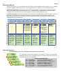


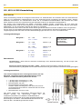


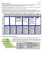
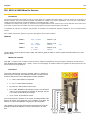
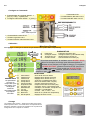


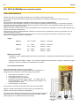
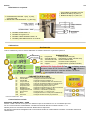


![[AC10] : HA502320U001 : Quickstart Guide to support the Parker](http://vs1.manualzilla.com/store/data/006217721_1-0f90eef9876ce441c4915239f16f04c8-150x150.png)