1
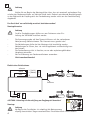
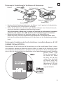
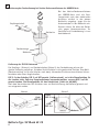
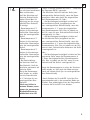
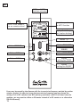
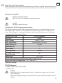
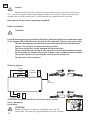
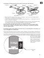
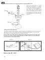
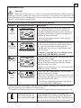
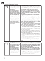
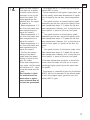
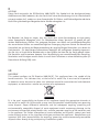
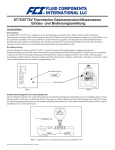
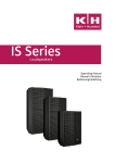
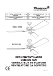
D Montage- und Bedienungsanleitung 2 GB Mounting and operating manual 10 F Instructions de montage et de service 14 - 16 I Istruzioni per il montaggio e l´uso 17 - 19 ROOM TEMP AUTO 1 SET TEMP °F AUTO 2 °C °F °C TIMER H 1 2 3 4 TIMER AUTO1 TIMER AUTO2 DELAY OFF > TEMP SET > H TIMER FB-FNK Advanced Equipment Class 1 Sub-class 20 433,9 MHz Funk-Fernbedienung für Deckenventilatoren RF Remote Control for Ceiling Fans AUTO1 oder AUTO2 Funktion aktiviert Voreingestellte Temperatur für AUTO Funktion ROOM TEMP AUTO 1 SET TEMP Aktuelle Raumtemperatur am Handsender °F AUTO 2 °C °F °C TIMER H 1 2 3 4 Anzeige für schwache Batterie (Batterie austauschen) TIMER H TEMP SET Taste LICHT und DIMMER Taste LICHT TIMER TIMER AUTO2 Taste DELAY OFF TIMER Taste AUTO 2 DELAY OFF Taste AUTO 1 > Taste TEMP SET AUTO1 > Tasten / Taste VENTILATOR TIMER Taste VENTILATOR EIN/AUS Eventuelle Fehlfunktionen könnten durch die Belegung der Trägerfrequenz durch ein anderes Funkprodukt im 434 MHz-Bereich (Garagentoröffner, Funkrauchmelder) verursacht sein. Um die Frequenz zu ändern, sind alle 4 DIP-Schalter von OFF auf ON zu schalten. Bringt dies keine Lösung, so ist als Alternative eine Infrarotfernbedienung anstatt einer Funkfernbedienung einzusetzen (FB-IR Advanced)! 2 D Über die Montage- und Bedienungsanleitung Bevor Sie das CasaFan Produkt benutzen, lesen Sie bitte diese Montage- und Bedienungsanleitung aufmerksam durch. Bewahren Sie die Anleitung griffbereit auf. Geben Sie das Produkt nie ohne Montage- und Bedienungsanleitung an andere Personen weiter. Zeichenerklärung Gefährliche elektrische Spannung Warnt den Benutzer vor Schäden, die durch elektrische Spannung verursacht werden. Achtung Besonderer Hinweis für den Benutzer. Beschreibung der Fernbedienung FB-FNK Advanced Die CasaFan Fernbedienung FB-FNK Advanced dient ausschließlich zur Steuerung von Deckenventilatoren mit und ohne Beleuchtung. Sie ermöglicht die Auswahl von 4 Geschwindigkeitsstufen sowie die Ein-/Ausschaltung. Eine eventuell vorhandene Beleuchtung am Ventilator kann unabhängig vom Betriebszustand des Motors ein- und ausgeschaltet und gedimmt werden. FB-FNK Advanced Technische Daten: 85229 Artikel-Nr. Nennspannung 230 Volt ~ 50 Hz Datenübertragung Funk (434 MHz-Bereich) Leistung Motor max. 115 Watt Schutzklasse I Drehzahlstufen 4 Leistung Beleuchtung max. 300 Watt Dimmung Beleuchtung ja Gewicht ca. 0,15 kg Technische Änderungen vorbehalten. Zulässige Umgebungstemperatur: - 10 °C bis + 40°C Inhalt der Verkaufsverpackung: FB-FNK Advanced 1 Handsender mit Wandhalterung 1 Empfangsteil - - Achtung Die CasaFan Fernbedienung auspacken, auf Vollständigkeit und sichtbare Beschädigungen prüfen. Verpackungsmaterial umweltbewusst entsorgen. 3 D Achtung Stellen Sie vor Beginn der Montage bitte sicher, dass ein eventuell vorhandener Zugschalter des Deckenventilators auf höchster Stufe steht. Dadurch entstehende Beschädigungen an der Elektronik des Empfangsteils der Fernbedienung werden nicht von der Gewährleistung abgedeckt! Das Gerät darf nur vollständig montiert betrieben werden! Montagehinweise Achtung CasaFan Fernbedienungen dürfen nur vom Fachmann unter Einhaltung der VDE 0100 installiert werden. - Die Spannungsangabe auf dem Typenschild muss mit der vorhandenen Netzspannung übereinstimmen. Das Hausnetz muss geerdet sein! Die Netzleitungen dürfen bei der Montage nicht beschädigt werden. Netzleitungen so führen, dass sie nicht eingeklemmt und beschädigt werden können. Die Fernbedienung nicht in feuchter, nasser oder explosionsgefährdeter Umgebung einsetzen. Nur zur Steuerung von Deckenventilatoren verwenden Nicht zweckentfremden! - schwarz braun blau L (Licht) L (Motor) N Out Elektrisches Schaltschema blau braun N L In Antenne ACHTUNG: Unbedingt die Beschriftung am Empfangsteil beachten! Montage 4 Achtung Vor Beginn der Installation ist unbedingt die Netzspannung allpolig abzuschalten! Gegen versehentliches Einschalten durch Dritte sichern! Platzierung der Fernbedienung bei Ventilatoren mit Deckenstange Skizze 1 Empfangseinheit Baldachin Deckenstange D Skizze 2 Baldachin Deckenstange 1. Montieren Sie die Empfangseinheit wie in den Skizzen 1 und 2 gezeigt in die Deckenhalterung. Die Antenne wird in den Baldachin eingelegt. 2. Führen Sie den elektrischen Anschluss gem. Schema auf Seite 4 durch. Achten Sie darauf, dass keine Leitungen eingeklemmt oder beschädigt werden! Falls die Leitungen L-Motor und L-Leuchte am Ventilator im Lieferzustand zusammen geklemmt sind, müssen diese VOR Anschluss der Fernbedienung getrennt werden! 3. Montieren Sie den Baldachin des Ventilators wieder an der Deckenhalterung. Stellen Sie sicher, dass der Zugschalter Ihres Ventilators auf höchster Stufe steht. Nach dem Einschalten der Netzspannung ist Ihr Ventilator mit der Fernbedienung betriebsbereit. Platzierung der Fernbedienung bei CasaFan-Ventilatoren in extraflacher Bauweise, z.B. FLAT, GLASHAUS FLAT oder OFFICE FAN Bitte montieren Sie das Empfangsteil der Fernbedienung wie auf der nachfolgenden Skizze 3 schematisch dargestellt. Nachdem der elektrische Anschluss erfolgt ist, kleben Sie das Empfangsteil mittels der beiliegenden Selbstklebepunkte an die Decke. Ist dies nicht möglich, z.B. bei sehr grobem Rauhputz, so muss die Empfangseinheit mit Kabelbindern an der Deckenmontageplatte gegen Herabfallen gesichert werden. Legen Sie das Antennenkabel in das Gehäuse ein. Stellen Sie sicher, dass der Zugschalter Ihres Ventilators auf höchster Stufe steht. Nach dem Einschalten der Netzspannung ist Ihr Ventilator mit der Fernbedienung betriebsbereit. 5 Platzierung der Fernbedienung bei Vortice-Deckenventilatoren der NORDIK-Serie Bei den Vortice-Deckenventilatoren der NORDIK-Serie wird die Empfangseinheit nach dem elektrischen Anschluss einfach in den oberen Baldachin eingelegt. Legen Sie das Antennenkabel in den Baldachin ein. Danach sichern Sie bitte den Baldachin gegen Herunterrutschen. Ihr Ventilator mit Fernbedienung ist nun betriebsbereit. Empfangseinheit Baldachin Deckenstange Baldachin Codierung der FB-FNK Advanced Die Empfangs- (Skizze 4) und Sendeeinheiten (Skizze 5) der Fernbedienung müssen die gleiche Codierung aufweisen. Schieben Sie die Schalter in die gewünschte Position Ihrer Wahl (Werkseinstellung ist für alle Schalter nach oben). Verwenden Sie hierzu einen kleinen Schraubendreher oder einen Kugelschreiber. DIP 5: Ist der Schalter DIP 5 auf OFF gesetzt (Lieferzustand), so ist die Dimmfunktion für die Leuchte aktiv. Soll eine Energiesparlampe verwendet werden, so muss DIP 5 auf ON gesetzt werden. Die Dimmfunktion ist dann deaktiviert (Licht nur AN/AUS). Nach dem Umschalten des DIP-Schalters muss zur Reinitalisierung die Batterie getrennt und neu eingesetzt werden. Skizze 4 Skizze 5 Code DIP 1-4 Licht DIP 5 12345 D Code DIP 1-4 Batterie Batterie Typ: 9V Block 6F 22 6 D ROOM TEMP AUTO 1 SET TEMP °F AUTO 2 °F GRUNDSÄTZLICHES °C °C TIMER H 1 2 3 4 Achtung Wenn Ihr Ventilator über einen Schalter zur Drehrichtungsänderung für Sommer- / Winterbetrieb verfügt, so darf dieser nur bei Stillstand der Flügel (Motor AUS) umgeschaltet werden! Bei Nichtbeachtung unterliegen Schäden am Motor und/oder der Fernbedienung nicht der Gewährleistung. TIMER Bedienung und Funktionen der Fernbedienung FB-FNK Advanced AUTO 1 AUTO 2 °FTaste °F LC-Display/FUNKTION Erklärung °C °C SET TEMP AUTO2 H 1 2 3 4 TIMER TIMER TIMER > H 1 2 3 4 TIMER TIMER TIMER Ventilator AN (Stufe 4) TIMER H 1 2 3 4 H Beleuchtungs-Anzeige H TIMER > AUTO1 TEMP SET TEMP SET > AUTO2 AUTO1 AUTO2 TEMP SET - Durch Drücken der Taste DELAY OFF erscheint das Symbol TIMER im LC-Display. Die Abschaltzeit läuft nun von 99 bis 0. Die Beleuchtung und der Ventilator schalten nach Ablauf der Verzögerung aus. TIMER TIMER AUTO1 DELAY OFF > Verzögerte Abschaltung (99 Sek.) des Ventilators und Beleuchtung, z.B. beim Verlassen des Raumes. TIMER TIMER > - Die Anzeige im Display wird nach ca. 40 Sek. ohne Tastendruck abgeschaltet. Zum Wiedereinschalten des Displays kann jede beliebigige Taste kurz gedrückt werden. - Bei schwacher Batterie leuchtet das Symbol „Batterie schwach“ (siehe Übersicht auf Seite 2). > H 1 2 3 4 °C - Drücken Sie die Taste LICHT-TIMER - das Symbol Licht Timer blinkt im Display. H - Mit den Tasten / kann nun die Abschaltzeit der Licht Timer-Einstellungen Leuchte von 1/2 Std. bis zu 24 Std. eingestellt werden. - Durch längeres Drücken (> 1 Sek.) der Taste LICHTTIMER wird die Einstellung gelöscht. AUTO1 TEMP SETTEMP SET AUTO2 H TIMER °C Ventilator TimerH Einstellung 1 2 3 4 H TIMER TIMER - Drücken Sie die Taste VENTILATOR-TIMER - das Symbol Ventilator Timer blinkt im Display. - Mit den Tasten / kann nun die Ausschaltzeit des Ventilators von 1/2 Std. bis zu 24 Std. eingestellt werden. - Durch längeres Drücken (> 1 Sek.) der Taste VENTILATOR-TIMER wird die Einstellung gelöscht. DELAY OFF DELAYTIMER OFF °F °C TIMER ROOM TEMP AUTO 1 SET TEMP H 4 °F AUTO 21 2 3 °F > °F AUTO 2 °C TIMER °F °C TIMER TIMER ROOM TEMP AUTO 1 SET TEMP AUTO2 AUTO2 AUTO1 > TEMP SET AUTO1 TIMER LICHT TIMER °F AUTO 2 °C TIMER DELAY OFF > AUTO2 TEMP SET AUTO1 AUTO2 H ROOM TEMP AUTO 1 SET TEMP TIMER TIMER VENTILATOR TIMER TIMER > 1 2 3 4 TIMER H > °F °C TIMER °F AUTO 2 °C TIMER Licht und Dimmer an DELAY OFF DELAY TIMER OFF DELAY OFF > ROOM TEMP AUTO 1 SET TEMP - Kurzes Drücken der Taste schaltet das Licht in der vorgewählten Helligkeit ein, ein weiteres kurzes Drücken schaltet das Licht aus. - Längeres Drücken (> 0,6 Sek.) der Taste dimmt das Licht langsam ab. Ist der DIP-Schalter 5 (s. Seite 6 unten) auf ON (Energiesparlampe), ist die Dimmung abgeschaltet und nur Licht EIN/AUS möglich! TIMER > LICHT UND DIMMER TIMER AUTO2 H °FH AUTO 21 2 3 °F 4 °C °C > TEMP SET > TIMER AUTO1 °F °C °F °C TIMER ROOM TEMP AUTO 1 SET TEMP DELAY OFF °F AUTO 2 °C - Einmaliges Drücken der Taste schaltet den Ventilator ein, ein weiteres Drücken schaltet den Vent. aus. - Zum Schutz des Motors läuft der Ventilator auf der höchsten Stufe an. Nach 5 Sek. wird auf die gewählte Stufe umgeschaltet. - Zum Umschalten der Geschwindigkeit zwischen den Stufen 1 und 4 werden die Tasten / gedrückt. ROOM TEMP AUTO 1 SET TEMP °F AUTO 2 °C VENTILATOR H EIN/AUS ROOM TEMP AUTO 1 SET TEMP Ventilator-LC-Anzeige > ROOM TEMP TIMER AUTO1 DELAY OFF > TEMP SET > H 7 H DELAY OFF TEMP SET > D > Automatische Temperaturprogramme TIMER AUTO2 TIMER AUTO1 Die Auto 1-Funktion ermöglicht es, mit dem Ventilator in Abhängigkeit von der Raumtemperatur zu lüften. Je weiter die Temperatur im Raum sinkt, desto langsamer läuft der Ventilator. Erreicht die Raumtemperatur einen Wert, der 7 °C unter der eingestellten Max.-Raumtemperatur liegt, schaltet der Ventilator ab. Ideal zum Lüften in warmen Räumen an heißen Sommerabenden, wenn der Ventilator nicht die ganze Nacht durchlaufen soll. ROOM TEMP AUTO 1 SET TEMP °F AUTO 2 °C °F °C TIMER H 1 2 3 4 TIMER AUTO1 TIMER Die Auto 2-Funktion ermöglicht es, mit dem Ventilator in Abhängigkeit von der Raumtemperatur zu lüften. Je weiter die Temperatur im Raum sinkt, desto langsamer läuft der Ventilator. Die max. Drehzahlstufe kann voreingestellt werden. TIMER AUTO2 DELAY OFF 8 > TEMP SET > H - Durch Drücken der AUTO 1 - Taste erscheint das AUTO 1 - Symbol im Display. Durch anschließendes Drücken der TEMP SET-Taste beginnt die Max.Raumtemperaturanzeige (rechter Wert) zu blinken. - Mit den Tasten / kann nun die gewünschte Max.-Raumtemperatur (16 - 32°C) eingestellt werden. 3 Sek. warten oder Drücken der Taste TEMP SET speichert die Einstellung. - Durch 2-maliges Drücken der AUTO 1 - Taste wird das Programm AUTO 1 gestartet. - Der Ventilator läuft auf Stufe 4 (höchste Stufe), wenn die Raumtemperatur höher oder gleich der eingestellten Max.-Raumtemperatur ist. Oder... - ...die Ventilatorgeschwindigkeit schaltet auf Stufe 3 (zweithöchste Stufe), wenn die Raumtemperatur 2 °C unter der eingestellten max. RaumTemperatur fällt. Oder... - ...die Ventilatorgeschwindigkeit schaltet auf Stufe 2, wenn die Raumtemperatur 4 °C unter die eingestellte Max.-Raumtemperatur fällt. Oder... - ...die Ventilatorgeschwindigkeit schaltet auf Stufe 1 (langsamste Stufe), wenn die Raumtemperatur 6 °C unter die eingestellte Max.Raumtemperatur fällt. Steigt die Raumtemperatur in einer der Zwischenstufen wieder an, läuft auch der Motor entsprechend auf höherer Stufe. Oder... - ... der Ventilator wird abgeschaltet, wenn die Raumtemperatur 7°C unter den eingestellten Max.-Raumtemperaturwert fällt. Danach bleibt der Ventilator auch bei wieder ansteigender Raumtemperatur abgeschaltet. - Zum Neustart des Programms die AUTO 1-Taste erneut drücken. - Durch Drücken der AUTO 2 - Taste erscheint das AUTO 2 - Symbol im Display. Durch anschließendes Drücken der TEMP SET-Taste beginnt die Max.Raumtemperaturanzeige (rechter Wert) zu blinken. - Mit den Tasten / kann nun die gewünschte Max.-Raumtemperatur (16 - 32°C) eingestellt werden. 3 Sek. warten oder Drücken der Taste TEMP SET speichert die Einstellung. - Nun kann mit den Tasten / die maximale Drehzahlstufe gewählt werden. Nach 3 Sekunden ohne Tastendruck werden die Werte gespeichert. TEMP S AUTO1 TIMER ... Sinkt die Raumtemperatur auf einen bestimmten Wert und darunter, läuft der Ventilator auf kleinster Drehzahlstufe weiter. Dieser Wert ist abhängig von der ausgewählten Max.-Drehzahl. Er beträgt: - Raumtemperatur 2°C kleiner als die voreingestellte Max.-Raumtemperatur bei voreingestellter Stufe 2 - Raumtemperatur 4°C kleiner als die voreingestellte Max.-Raumtemperatur bei voreingestellter Stufe 3 - Raumtemperatur 6°C kleiner als die voreingestellte Max.-Raumtemperatur bei voreingestellter Stufe 4 - Bei Voreinstellung der kleinsten Stufe als Max-Drehzahl, läuft der Ventilator permanent auf kleinster Stufe. Steigt die Raumtemperatur wieder an, erhöht sich die Drehzahlstufe in 2°-Schritten bis zur voreingestellten Max.Drehzahl. Ideal zum Lüften in warmen Räumen, wenn immer ein permanenter Mindestluftstrom gewährleistet sein soll. TIMER AUTO2 LAY OFF > D - Durch 2-maliges Drücken der AUTO 2 - Taste wird das Programm AUTO 2 gestartet. - Der Ventilator läuft auf höchster Stufe (max. voreingestellte Drehzahlstufe), wenn die Raumtemperatur höher oder gleich der eingestellten Max.-Raumtemperatur ist. Oder... - ...die Ventilatorgeschwindigkeit schaltet auf die zweithöchste Stufe (ausgehend von der max. voreingestellten Drehzahlstufe), wenn die Raumtemperatur 2 °C unter der eingestellten Max.-Raumtemperatur fällt. Dies ist jedoch nur der Fall, wenn als max. Drehzahlstufe die Stufe 2 voreingestellt ist. Oder... - ...die Ventilatorgeschwindigkeit schaltet auf die dritthöchste Stufe (ausgehend von der max. voreingestellten Drehzahlstufe), wenn die Raumtemperatur 4 °C unter die eingestellte Max.Raumtemperatur fällt. Dies ist jedoch nur der Fall, wenn als max. Drehzahlstufe mindestens die Stufe 3 voreingestellt ist. Oder... - ...die Ventilatorgeschwindigkeit schaltet auf die langsamste Stufe, wenn die Raumtemperatur 6 °C unter die eingestellte Max.-Raumtemperatur fällt. Dies ist jedoch nur der Fall, wenn als max. Drehzahlstufe die Stufe 4 voreingestellt ist. Steigt die Raumtemperatur in einer der Zwischenstufen wieder an, läuft auch der Motor entsprechend auf höherer Stufe (bis zur voreingestellten Max.-Drehzahlstufe) - Durch Drücken der Taste AUTO 2 wird das Programm beendet und in den manuellen Modus geschaltet. Zum wiederholten Start des Programmes ist erneut die Taste AUTO 2 zu drücken. 9 GB AUTO1 or AUTO2 function activated GB Preset temperature for AUTO function ROOM TEMP AUTO 1 SET TEMP Current room temperature on remote control °F AUTO 2 °C °F °C TIMER H 1 2 3 4 Display for battery low (replace battery) TIMER H TEMP SET Button LIGHT and DIMMER Button LICHT TIMER TIMER AUTO2 Button DELAY OFF TIMER Button AUTO 2 DELAY OFF Button AUTO 1 > Button TEMP SET AUTO1 > Button / Button ceiling fan TIMER Button ceiling fan ON/OFF Errors may be caused by interference with the transmission frequency emitted by another wireless product. In order to change the transmission frequency you may change the setting of all 4 DIP switches from OFF (delivery condition) to ON. If this does solve the problem, you may want to utilize an IR remote instead of an RF remote as an alternative (FB-IR Advanced). 10 About this operating instructions Before using the CasaFan product, read the operating instructions carefully. Keep the operating instructions within reach. Never pass the fan onto another person without the operating instructions. Explanation of symbols: Dangerous electric voltage Warn the user of the dangers caused by electricity. Careful Particular note for the user. Description of FB-FNK Advanced remote control The CasaFan remote control FB-FNK Advanced exclusively serves to control ceiling fans with and without lights. It allows for the selection of 4 speed settings as well as for on/off switching. If the ceiling fan is equipped with lights these may be switched on or off or dimmed, irrespective of the fan motor function. Technical data: Type FB-FNK Advanced 85229 Code-Nbr.: Mains voltage: 230 Volt ~ 50 Hz Data transmission: Radio freqency (434 MHz) Power motor max.: 115 Watt Protection clas: I No of speeds: 4 Power light max.: 300 Watt Dimming Tungsten bulb/ ON-OFF ESL bulb Weight (kg): yes ca. 0,15 kg CasaFan reserves the right to make improving changes on products on sale. Permissible ambient temperature: - 10 ° C to + 40 °C Content of packing: FB-FNK Advanced 1 remote control with wall bracket 1 receiver unit - - Caution! Unpack the CasaFan remote control, check if everything is present and for visible signs of damage. Dispose of packaging taking the environment into account and keep out of the reach of children. 11 GB GB Caution Before starting with the installation, please make sure that the pull switch on the fan is set to the highest speed. Any damage caused to the circuitry of the remote control‘s receiver, due to faulty installation, is not covered by the remote control‘s warranty. Only operate the unit when completely assembled! Before installation: Attention! CasaFan remote controls may only be installed by a professional electrician under observance of the German VDE 0100 industrial standard (or the applicable federal and/or state code). The specified voltage on the model tag must correspond with the available mains voltage. The wiring in the house must be grounded! The mains wiring may not be damaged during installation. Please install the mains wiring in such a way that it cannot be pinched or damaged. Do not employ the remote control unit in humid, wet or explosive environments. The remote control unit must only be used to control ceiling fans Do not use for other purposes! black brown blue L (light) L (motor) N Out Electrical diagram blue brown N L In antenna ATTENTION! The observance of the instructions on the receiver unit is mandatory! Installation ATTENTION! Before starting the installation and before accessing the connection, all current carrying conductors are to be isolated. 12 GB Installation of remote control receiver unit for ceiling fans with downrod diagram 2 diagram 1 Receiver Canopy Downrod Canopy Downrod 1. Please install the receiver unit as shown in diagrams 1 and 2 within the canopy bracket. The antenna is installed inside the canopy. 2. Please install the electrical wiring according to the diagram on p. 4. Make certain that no lines are pinched or damaged! If the switched line to the motor and the switched line to the lights are connected inside the ceiling fan these must be separated PRIOR to installing the remote control. 3. Please fasten the canopy of the ceiling fan on the ceiling bracket. Please make sure that the pull switch of your ceiling fan is set to the highest speed. Once the mains voltage is switched on again, the ceiling fan is available to operation with the remote control. Installation of the remote control of CasaFan fans in an extremely flat construction, e.g. FLAT, GLASHAUS FLAT or OFFICE FAN Please install the receiver unit of the remote as shown in diagram 3. Once the device is electrically installed, you may stick the receiver unit to the ceiling with the double-sided sticky points. If this fails, e.g. when the ceiling decoration is too rough, you may want to attach the receiver unit to the ceiling plate by means of cable ties. Please put the antenna cable in the housing. Please make sure that the pull switch of your ceiling fan is set to the highest speed. Once the mains voltage is switched on again, the ceiling fan can be operated by means of the remote control. Fan Housing Cover 13 Installation of receiver unit in Vortice ceiling fans of the NORDIK series Once the receiving unit has been electrically connected, it is placed in the upper canopy kit of the Vortice ceiling fans of the NORDIK series. Please put the antenna cable in the canopy. Next, you must fasten the canopy to the ceiling. Your fan and remote control are now ready for operation. Receiver Canopy Downrod Lower Canopy Coding of the FB-FNK Advanced The remote control receiver (diagram 4) and transmitter unit (diagram 5) must have the same code. Put the switch in the desired position you selected (factory default is up for all switches). Please use a small screwdriver or a ballpoint to do this. DIP 5: If DIP 5 set to OFF (delivery condition) the dimming function for the light kit is activated. For using an enegry saving lamp (ESL) set DIP 5 to ON. This deactivates the dimming function (Licht only ON/OFF). diagram 4 diagram 5 Code DIP 1-4 Light DIP 5 12345 GB Code DIP 1-4 Battery Battery Typ: 9V / 6F22 14 GB ROOM TEMP AUTO 1 SET TEMP °F AUTO 2 °F FUNDAMENTAL ISSUE °C °C TIMER H 1 2 3 4 Attention! When your ceiling fan has a switch to reverse the rotation from summer to winter mode you may only change the setting when the blades are standing still (motor OFF)! If this fundamental issue is not observed, any resulting damage to the motor and/or the remote control is not covered by the warranty. TIMER Operation and functions of the remote control FB-FNK Advanced AUTO 1 °F AUTO 2 °F Button LC-Display/FUNCTION Description °C °C SET TEMP 1 2 3 4 °F AUTO 2 °C FAN ON/OFF TIMER H > DELAY OFF TEMP SET °F °C TIMER 1 2 3 4 > H > AUTO1 TEMP SET TEMP SET TIMER ROOM TEMP AUTO 1 SET TEMP °FH AUTO 21 2 3 °F 4 °C °C TIMERTIMER SETTING FAN TIMER H H 1 2 3 4 TIMER > AUTO1 TEMP SET TEMP SET AUTO2 °F °C LIGHT TIMER SETTING - Press the FAN-TIMER button - the light timer symbol blinks on the display. - With the buttons / you are able to adjust the time at which the fan switches itself off, ranging from 30 minutes to 24 hours. - By pressing and holding (> 1 sec.) the button FANTIMER the setting is deleted. - Press the LIGHT-TIMER button - the fan timer symbol blinks on the display. - With the / buttons you are able to adjust the time at which the light switches itself off, ranging from 30 minutes to 24 hours. - The setting is deleted by pressing and holding (> 1 sec.) the LIGHT-TIMER button. AUTO2 AUTO1 AUTO2 TIMER AUTO2 AUTO1 TIMER TIMER DELAY OFF > TIMER TIMER > H > - The indication on the display is switched off after approx. 40 seconds of no button activity. Touching any button will switch on the display again. - The symbol „Low Battery“ lights up in case of a low battery voltage (see overview on p. 10). 1 2 3 4 TIMER TEMP SET °F AUTO 2 °C DELAY OFF DELAY TIMER OFF H ROOM TEMP AUTO 1 SET TEMP > °F °C LIGHT AND DIMMER ON H TIMER °F AUTO 2 °C TIMER AUTO2 AUTO1 > AUTO2 AUTO1 AUTO2 TEMP SET AUTO1 TIMER ROOM TEMP AUTO 1 SET TEMP H TIMER DELAY OFF > LIGHT TIMER TIMER A short push of the button switches the light on in the preselected dimmer setting. Push the button again and the light switches itself off. - Longer pressing (> 0,6 sec.) the button slowly dims the light. If switch 5 (see page 14) is on (Energy saving lamp), only Light ON/OFF is possible. TIMER TIMER > FAN TIMER H 1 2 3 4 H DISPLAY LIGHT > H FAN ON (Speed 4) TIMER TIMER > TIMER 1 2 3 4 TIMER H TIMER °F °C °FH AUTO 21 2 3 °F 4 °C °C - Push the button once and the fan switches on. Push the button again and the fan switches off. - In order to protect the motor, the fan starts out at the highest speed. After 5 seconds the control unit switches to the desired speed. - For switching between speeds 1 and 4 you must push the buttons /. DELAY OFF DELAY TIMER OFF DELAY OFF °F AUTO 2 °C TIMER TIMER LIGHT AND DIMMER AUTO2 H > TEMP SET TIMER AUTO1 TIMER ROOM TEMP AUTO 1 SET TEMP °F °C TIMER ROOM TEMP AUTO 1 SET TEMP ROOM TEMP AUTO 1 SET TEMP °F AUTO 2 °C FAN-LC-DISPLAY ROOM TEMP AUTO 1 SET TEMP > AUTO2 H TIMER TIMER > ROOM TEMP TIMER AUTO1 DELAY OFF > TEMP SET > H Delayed off function (99 sec.) of fan and light, e.g. when you leave the room. - Pressing the button DELAY OFF activates the symbol TIMER on the LCD display. The delayed off function counts back from 99 to 0. The light and the fan are switched off when the delay time expires. 15 H DELAY OFF TEMP SET > GB > Automated Temperature Programs TIMER AUTO2 TIMER AUTO1 The AUTO 1 function makes it possible to run the fan depending on room temperature. The more the temperature in the room drops, the more the fan speed is reduced. The fan switches off, once the room temperature reaches a value of 7 °C below the set max. room temperature. This function is ideal for ventilation of hot rooms on hot summer nights when the fan should not run all night. ROOM TEMP AUTO 1 SET TEMP °F AUTO 2 °C °F °C TIMER H 1 2 3 4 TIMER AUTO1 TIMER The AUTO 2 function makes it possible to run the fan depending on room temperature. The more the temperature in the room drops, the more the fan speed is reduced. The max. fan speed may be preset. TIMER AUTO2 DELAY OFF 16 > TEMP SET > H - The symbol AUTO 1 is activated on the display by pressing the button AUTO 1. By pressing the button TEMP SET again, the max. room temperature indication (right value) starts to blink. - With the / buttons you may now set the max. room temperature (16 °C - 32° C). Waiting 3 seconds or pressing the button TEMP SET saves the setting. - By pressing the button AUTO 1 twice program AUTO 1 is started. - The fan operates at speed 4 (highest speed) when room temperature is higher than or equal to the set max. room temperature. Or... - ...fan speed switches to speed 3 (second highest speed), when room temperature drops 2 °C below the set max. room temperature. Or... - ...fan speed switches to speed 2 (second highest speed), when room temperature drops 4 °C below the set max. room temperature. Or... - ...fan speed switches to speed 1 (lowest speed), when room temperature drops 6 °C below the set max. room temperature. If the room temperature increases during one of the phases then the motor will also run at a correspondingly higher speed. Or... - ... the fan is switched off when room temperature drops 7 °C below the set max. room temperature value. Upon this, the fan will remain switched off even when the room temperature rises. - Press button AUTO 1 again to restart the program. - By pressing the button AUTO 2, the symbol AUTO 2 is activated on the display. By pressing the button TEMP SET again, the max. room temperature indication (right value) starts to blink. - With the / buttons you may now set the max. room temperatur (16 °C - 32 °C). Waiting 3 seconds or pressing the button TEMP SET saves the setting. - Now the max. fan speed may be selected by means of the / buttons. The values are saved after 3 seconds without pressing any button. TEMP S AUTO1 TIMER ... When the room temperature drops to, or below a certain value, the fan continues to run at the lowest fan speed. This value depends on the selected max. fan speed. It amounts to: - Room temperature 2 °C less than the preset max. room temperature at a preset fan speed 2 - Room temperature 4 °C less than the preset max. room temperature at a preset fan speed 3 - Room temperature 6 °C less than the preset max. room temperature at a preset fan speed 4 - The fan runs permanently at the lowest speed when the lowest setting is preset as the max. fan speed. If the room temperature rises again, the fan speed will increase in 2 ° steps up to the preset max fan speed. This function is ideal for ventilation of hot rooms when a permanent, minimum flow of air must be guaranteed. TIMER AUTO2 LAY OFF > GB - The program AUTO 2 is started by pressing the button AUTO 2 twice. - The fan operates at the highest speed (max. preset fan speed), when room temperature is higher than or equal to the set max. room temperature. Or... - ...fan speed switches to second highest speed (depending on the max. preset fan speed), when room temperature drops 2 °C below the set max. room temperature. However, this is only the case when speed 2 is preset as the max. fan speed. Or... - ...fan speed switches to third highest speed (depending on the max. preset fan speed), when room temperature drops 4 °C below the set max. room temperature. However, this is only the case when at least speed 3 is preset as the max. fan speed. Or... - ...fan speed switches to the lowest speed, when room temperature drops 6 °C below the set max. room temperature. However, this is only the case when speed 4 is preset as the max. fan speed. If the room temperature increases in one of the phases then the motor will also run at a correspondingly higher speed (up to the preset max. fan speed). - The program is cancelled by pressing the button AUTO 2 and the fan operates in the manual mode. To start the program again you must press the button AUTO 2 again. 17 D ACHTUNG Dieses Gerät entspricht der EG-Richtlinie 2002/96/EG. Das Symbol mit der durchgestrichenen Abfalltonne am Gerät bedeutet, dass das Gerät nach seiner Aussonderung nicht im Haushaltsmüll entsorgt werden darf, sondern an einer Sammelstelle für Elektro- und Elektronikgeräte oder beim Kauf eines gleichwertigen Neugerätes beim Händler abzugeben ist. Der Benutzer hat Sorge zu tragen, dass das Gerät nach seiner Aussonderung an einer geeigneten Sammelstelle abgegeben wird. Ein Nichtbeachten dieser Vorschrift ist gemäß der geltenden Abfallordnung strafbar. Das geeignete Sortieren von Abfall und nachfolgende Recyceln des aussortierten Gerätes zur umweltverträglichen Entsorgung trägt zum Schutz von Umwelt und Gesundheit bei und dient der Wiederverwendung der recyclingfähigen Materialien, aus denen das Gerät besteht. Für detailliertere Informationen bezüglich der verfügbaren Sammelsysteme wenden Sie sich an lhre örtliche Behörde oder an den Händler, bei dem Sie das Gerät gekauft haben. Die Hersteller und Importeure kommen ihrer Verpflichtung zum umweltfreundlichen Recycling, Verarbeiten und Entsorgen sowohl direkt als auch durch Teilnahme an einem Kollektivsystem (in Deutschland Stiftung EAR) nach. GB IMPORTANT This product conforms to EU Directive 2002/96/EC. This appliance bears the symbol of the barred waste bin. This indicates that, at the end of its useful life, it must not be disposed of as domestic waste, but must be taken to a collection centre for waste electrical and electronic equipment, or returned to a retailer on purchase of a replacement. It is the user‘s responsibility to dispose of this appliance trough the appropriate channels at the end of its useful life. Failure to do so may incur the penalties established by laws governing waste disposal. Proper differential collection, and the subsequent recycling, processing and environmentally compatible disposal of waste equipment avoids unnecessary damage to the environment and possible related health risks, and also promotes recycling of the materials used in the appliance. For further information on waste collection and disposal, contact your local waste disposal service, or the shop from which you purchased the appliance. Manufacturers and importers fulfil their responsibilities for recycling, processing and environmentally compatible disposal either directly or by participating in collective systems. KONFORMITÄTSERKLÄRUNG gem. Gesetz über Funkanlagen und Telekommunikationsendeinrichtungen (FTEG) und Richtlinie 1999/5/EG (R&TTE) Declaration of Conformity in accordance with the Radio and Telecommunications Terminal Equipment Act (FTEG) and Directive 1999/5/EC (R&TTE Directive) Hersteller/Manufacturer EVT/Casafan-Ventilatoren Inh.: Wolfgang Kissling Gelnhäuser Str. 35 D 63505 Langenselbold Fernbedienung für Deckenventilatoren / Remote Control for ceiling fans (Transmitter+receiver) Identification: FB FNK Advanced (AS-019-T + AS-047-EMC) Oben genanntes Produkt entspricht bei bestimmungsgemäßer Verwendung den grundlegenden Anforderungen des § 3 und den übrigen einschlägigen Bestimmungen des FTEG (Artikel 3 der R&TTE) / Above product complys at designated use with the basic requirements of § 3 and remaining regulations FTEG (Article 3 of R&TTE) Das oben beschriebene Produkt ist konform mit den Anforderungen der folgenden Dokumente / The above product is conforming with the requirements of following documents: EN 300 220-2 V2.1.2:2007 EN 301 489-1 V1.8.1:2008 EN 301 489-3 V1.4.1:2002 EN 60215:1989+A1+A2 EN 50371:2002 Langenselbold 05.02.2010 Produktänderungen, die der Verbesserung dienen, behalten wir uns ohne besondere Ankündigung vor. CasaFan reserves the right to make improving changes on products on sale. CasaFan * Otto-HZahn-Str. 3 * 63594 Hasselroth 20 ©CasaFan 2012