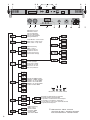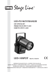
1
LED-DMX-LICHTEFFEKT-PANEL LED DMX LIGHT EFFECT PANEL BARRE DMX À LEDS PANNELLO DMX PER EFFETTI DI LUCE CON LED RGBL-412DMX Bestellnummer 38.6440 BEDIENUNGSANLEITUNG • INSTRUCTION MANUAL MODE D’EMPLOI • ISTRUZIONI PER L’USO • MANUAL DE INSTRUCCIONES INSTRUKCJA OBSŁUGI • VEILIGHEIDSVOORSCHRIFTEN SIKKERHEDSOPLYSNINGER • SÄKERHETSFÖRESKRIFTER • TURVALLISUUDESTA D A CH F B CH Bevor Sie einschalten … GB Before switching on … Wir wünschen Ihnen viel Spaß mit Ihrem neuen Gerät von „img Stage Line“. Bitte lesen Sie diese Bedienungsanleitung vor dem Betrieb gründlich durch. Nur so lernen Sie alle Funktionsmöglichkeiten kennen, vermeiden Fehlbedienungen und schützen sich und Ihr Gerät vor eventuellen Schäden durch unsachgemäßen Gebrauch. Heben Sie die Anleitung für ein späteres Nachlesen auf. We wish you much pleasure with your new “img Stage Line” unit. Please read these operating instructions carefully prior to operating the unit. Thus, you will get to know all functions of the unit, operating errors will be prevented, and yourself and the unit will be protected against any damage caused by improper use. Please keep the operating instructions for later use. Der deutsche Text beginnt auf der Seite 4. The English text starts on page 10. Avant toute installation … I Nous vous souhaitons beaucoup de plaisir à utiliser cet appareil “img Stage Line”. Lisez ce mode dʼemploi entièrement avant toute utilisation. Uniquement ainsi, vous pourrez apprendre lʼensemble des possibilités de fonctionnement de lʼappareil, éviter toute manipulation erronée et vous protéger, ainsi que lʼappareil, de dommages éventuels engendrés par une utilisation inadaptée. Conservez la notice pour pouvoir vous y reporter ultérieurement. Prima di accendere … Vi auguriamo buon divertimento con il vostro nuovo apparecchio di “img Stage Line”. Leggete attentamente le istruzioni prima di mettere in funzione lʼapparecchio. Solo così potete conoscere tutte le funzionalità, evitare comandi sbagliati e proteggere voi stessi e lʼapparecchio da eventuali danni in seguito ad un uso improprio. Conservate le istruzioni per poterle consultare anche in futuro. Il testo italiano inizia a pagina 22. La version française se trouve page 16. E Antes de la utilización … PL Le deseamos una buena utilización para su nuevo aparato “img Stage Line”. Por favor, lea estas instrucciones de uso atentamente antes de hacer funcionar el aparato. De esta manera conocerá todas las funciones de la unidad, se prevendrán errores de operación, usted y el aparato estarán protegidos en contra de todo daño causado por un uso inadecuado. Por favor, guarde las instrucciones para una futura utilización. Przed uruchomieniem … Życzymy zadowolenia z nowego produktu “img Stage Line”. Dzięki tej instrukcji obsługi będą państwo w stanie poznać wszystkie funkcje tego urządzenia. Stosując się do instrukcji unikną państwo błędów i ewentualnego uszkodzenia urządzenia na skutek nieprawidłowego użytkowania. Prosimy zachować instrukcję. Tekst polski zaczyna się na stronie 34. La versión española comienza en la página 28. NL B Voor u inschakelt … DK Wij wensen u veel plezier met uw nieuwe apparaat van “img Stage Line”. Lees de veiligheidsvoorschriften grondig door, alvorens het apparaat in gebruik te nemen. Zo behoedt u zichzelf en het apparaat voor eventuele schade door ondeskundig gebruik. Bewaar de handleiding voor latere raadpleging. Før du tænder … Tillykke med dit nye “img Stage Line” produkt. Læs sikkerhedsanvisningerne nøje før ibrugtagning, for at beskytte Dem og enheden mod skader, der skyldes forkert brug. Gem manualen til senere brug. Sikkerhedsanvisningerne findes på side 41. De veiligheidsvoorschriften vindt u op pagina 40. S Innan du slår på enheten … Vi önskar dig mycket glädje med din nya “img Stage Line” produkt. Läs igenom säkerhetsföreskrifterna innan enheten tas i bruk för att undvika skador till följd av felaktig hantering. Behåll instruktionerna för framtida bruk. Säkerhetsföreskrifterna återfinns på sidan 42. FIN Ennen kytkemistä … Toivomme Sinulle paljon miellyttäviä hetkiä uuden “img Stage Line” laitteen kanssa. Ennen laitteen käyttöä pyydämme Sinua huolellisesti tutustumaan turvallisuusohjeisiin. Näin vältyt vahingoilta, joita virheellinen laitteen käyttö saattaa aiheuttaa. Ole hyvä ja säilytä käyttöohjeet myöhempää tarvetta varten. Turvallisuusohjeet löytyvät sivulta 43. ® w w w.imgstageline.com 2 1 2 3 4 4 2 1 5 2 1 3 MIN SAFETY EYE ATTACH SAFETY CABLE HERE 2 DMX IN DMX OUT MENU/ESC DOWN UP MIC ENTER MAX SENSITIVITY 230 V~ / 50 Hz 1 3 MIN DMX IN DMX OUT 6 7 MENU/ESC DOWN UP ENTER 8 9 MAX MIC SENSITIVITY 10 11 230 V~ / 50 Hz 12 13 Firmware-Version Firmware version Version Firmware Versione Firmware Versión del Firmware Wersja firmwareʼa Slave-Modus • Slave mode Mode slave • Modo slave Modo Slave • Tryb slave Musiksteuerung Music control Gestion musique Comando musica Control por música Sterowanie muzyką Farbstrahler Colour spotlight Projecteur couleur Proiettore di colori Proyector de color Kolorowy reflektor Anzahl der DMX-Kanäle Number of DMX channels Nombre de canaux DMX Numero dei canali DMX Número de canales DMX Liczba kanałów DMX MENU/ESC UP DOWN ENTER automatisch ablaufende Programme Programs running automatically Programmes à déroulement automatique Programmi a svolgimento automatico Los programas se ejecutan automáticamente Programy automatyczne DMX-Steuerung DMX control Gestion DMX Comando DMX Control DMX Sterowanie DMX 3 Menüstruktur • Menu structure Structure du menu • Struttura del menù Estructura del menú • Struktura menu D A Auf der ausklappbaren Seite 3 finden Sie alle beschriebenen Bedienelemente und Anschlüsse. 1 Übersicht der Bedienelemente und Anschlüsse 1 Feststellschrauben für die Montagewinkel CH Inhalt 2 Montagewinkel (2 ×) zum Festschauben des Geräts an einer Wand oder Decke 1 Übersicht der Bedienelemente und Anschlüsse . . . . . . . . . . . . . . . . . . . . . 4 3 Sicherungsöse zum Befestigen eines Fangseils 2 Hinweise für den sicheren Gebrauch . . . . . 4 5 Montagebügel 3 Einsatzmöglichkeiten . . . . . . . . . . . . . . . . . 5 4 Montage . . . . . . . . . . . . . . . . . . . . . . . . . . . . 5 5 Inbetriebnahme . . . . . . . . . . . . . . . . . . . . . . 5 6 XLR-Einbaustecker DMX IN: DMX-Signaleingang zum Anschluss eines Lichtsteuergerätes oder an den DMX-Signalausgang eines anderen DMX-gesteuerten Gerätes 6 Bedienung . . . . . . . . . . . . . . . . . . . . . . . . . . 5 6.1 Bedienung über das Menü . . . . . . . . . . . . . . 5 6.2 Farbstrahler . . . . . . . . . . . . . . . . . . . . . . . . . 6 6.3 Automatisch ablaufende Programme . . . . . . 6 6.4 Musiksteuerung . . . . . . . . . . . . . . . . . . . . . . 6 6.5 Synchrone Steuerung mehrerer RGBL-412DMX (Master-Slave-Modus) . . . . 6 6.6 Betrieb mit einem DMX-Steuergerät . . . . . . 7 6.6.1 DMX-Anschluss . . . . . . . . . . . . . . . . . . . . . 7 6.6.2 Anzahl der DMX-Kanäle einstellen . . . . . . 7 4 Feststellschrauben für den Montagebügel 7 XLR-Buchse DMX OUT: DMX-Signalausgang zum Anschluss an den DMX-Eingang eines weiteren DMX-gesteuerten Gerätes 8 Tasten zur Auswahl des Betriebsmodus und zum Ändern von Einstellungen über das Menü 9 Display 10 Mikrofon zur Musiksteuerung 11 Regler SENSITIVITY für die Ansprechempfindlichkeit bei Musiksteuerung über das Mikrofon (10) 12 Netzbuchse zum Anschluss an eine Steckdose (230 V~/50 Hz) über das beiliegende Netzkabel 13 Halterung für die Netzsicherung Eine geschmolzene Sicherung nur durch eine gleichen Typs ersetzen. 6.6.3 DMX-Startadresse einstellen . . . . . . . . . . 7 6.6.4 DMX-Kanäle und -Funktionen . . . . . . . . . . 8 2 6.7 Anzeige der Firmware-Version . . . . . . . . . . . 9 Das Gerät entspricht allen relevanten Richtlinien der EU und ist deshalb mit gekennzeichnet. 7 Reinigung des Gerätes . . . . . . . . . . . . . . . 9 8 Technische Daten . . . . . . . . . . . . . . . . . . . . 9 Hinweise für den sicheren Gebrauch WARNUNG Das Gerät wird mit lebensgefährlicher Netzspannung versorgt. Nehmen Sie deshalb nie selbst Eingriffe am Gerät vor. Durch unsachgemäßes Vorgehen besteht die Gefahr eines elektrischen Schlages. Beachten Sie auch unbedingt folgende Punkte: G Verwenden Sie das Gerät nur im Innenbereich und schützen Sie es vor Tropf- und Spritzwasser, hoher Luftfeuchtigkeit und Hitze (zulässiger Einsatztemperaturbereich 0 – 40 °C). G Stellen Sie keine mit Flüssigkeit gefüllten Gefäße, z. B. Trinkgläser, auf das Gerät. G Nehmen Sie das Gerät nicht in Betrieb oder ziehen Sie sofort den Netzstecker aus der Steckdose, 1. wenn sichtbare Schäden am Gerät oder am Netzkabel vorhanden sind, 4 2. wenn nach einem Sturz oder Ähnlichem der Verdacht auf einen Defekt besteht, 3. wenn Funktionsstörungen auftreten. Geben Sie das Gerät in jedem Fall zur Reparatur in eine Fachwerkstatt. G Ziehen Sie den Netzstecker nie am Kabel aus der Steckdose, fassen Sie immer am Stecker an. G Wird das Gerät zweckentfremdet, nicht sicher montiert, nicht richtig angeschlossen, falsch bedient oder nicht fachgerecht repariert, kann keine Haftung für daraus resultierende Sachoder Personenschäden und keine Garantie für das Gerät übernommen werden. Soll das Gerät endgültig aus dem Betrieb genommen werden, übergeben Sie es zur umweltgerechten Entsorgung einem örtlichen Recyclingbetrieb. 3 Einsatzmöglichkeiten Das Lichteffekt-Panel RGBL-412DMX dient zur Effektbeleuchtung (z. B. zum Abstrahlen von farbigem Licht oder zum Erzeugen von Lauflicht- und Stroboskopeffekten) und ist für den Einsatz auf Bühnen, in Diskotheken etc. geeignet. Als Lichtquelle sind 16 extrem helle RGBW-LEDs eingesetzt. Das Lichteffekt-Panel ist für die Steuerung über ein DMX-Lichtsteuergerät ausgelegt (wahlweise 4, 6, 10, 18, 32 oder 34 DMX-Kanäle). Es kann aber auch ohne Steuergerät betrieben werden, entweder als Einzelgerät oder zusammengeschaltet mit mehreren RGBL-412DMX im Master-Slave-Modus. 4 Montage Platzieren Sie das Gerät immer so, dass im Betrieb eine ausreichende Luftzirkulation gewährleistet ist. Die Lüftungsöffnungen am Gehäuse dürfen auf keinen Fall abgedeckt werden. WARNUNG Das Lichteffekt-Panel muss fachgerecht und sicher montiert werden. Wird es an einer Stelle installiert, unter der sich Personen aufhalten können, muss es zusätzlich gesichert werden [z. B. durch ein Fangseil; das Fangseil durch die Sicherungsöse (3) führen und so befestigen, dass der Fallweg des Gerätes nicht mehr als 20 cm betragen kann]. werden, z. B. mit einer stabilen Montageschraube oder einer Lichtstrahler-Halterung (C-Haken) an einer Traverse. 2. Alternativ dazu lässt sich das Gerät auch über die zwei Montagewinkel (2) an einer Wand oder Decke montieren oder auf dem Boden aufstellen. Die Winkel mit jeweils einer Griffschraube (1) links und rechts am Gerät befestigen. D A CH Zum Ausrichten des Geräts die zwei Feststellschrauben (1 oder 4) lösen. Die gewünschte Neigung des Geräts einstellen und die Schrauben wieder festziehen. 5 Inbetriebnahme WARNUNG Blicken Sie nicht für längere Zeit direkt in die Lichtquelle, das kann zu Augenschäden führen. Beachten Sie, dass sehr schnelle Lichtwechsel bei fotosensiblen Menschen und Epileptikern epileptische Anfälle auslösen können! Das beiliegende Netzkabel zuerst in die Netzbuchse (12) stecken und anschließend in eine Steckdose (230 V~/ 50 Hz). Das Gerät ist damit eingeschaltet. Das Display (9) zeigt für einige Sekunden die letzte Einstellung an (Abb. 2) und erlischt anschließend. Hinweis: Das Gerät verfügt über einen Überhitzungsschutz. Dadurch schaltet es sich bei zu hoher Temperatur ab und nach dem Abkühlen automatisch wieder ein. 6 Bedienung Das Auswählen des Betriebsmodus und der verschiedenen Funktionen erfolgt über ein Menü (Abb. 2) mit den Tasten MENU / ESC, UP, DOWN und ENTER (8). Zur Bedienung über ein DMXLichtsteuergerät siehe Kapitel 6.6. 6.1 Bedienung über das Menü 1) Die Taste MENU / ESC so oft drücken, bis sich die Anzeige im Display nicht mehr ändert. Damit ist die oberste Menüebene erreicht ( Abb. 2 ganz links). 2) Mit der Taste UP oder DOWN den gewünschten Menüpunkt anwählen. Wird eine Fläche angestrahlt, sollte der Abstand zur Fläche mindestens 50 cm betragen. 3) Die Taste ENTER drücken. Das Display zeigt jetzt die aktuelle Einstellung des gewählten Menüpunkts an. 1. Das Lichteffekt-Panel kann über seinen Montagebügel (5) an geeigneter Stelle festgeschraubt 4) Mit der Taste UP oder DOWN die Einstellung ändern. 5 D A CH 5) Wenn Untermenüpunkte vorhanden sind, können diese mit der Taste ENTER aufgerufen werden und deren Einstellungen mit der Taste UP oder DOWN geändert werden. 6) Zum Speichern einer Einstellung die Taste ENTER drücken. 7) Für weitere Einstellungen wieder mit dem Bedienschritt 1 beginnen. Wird einige Sekunden lang keine Taste gedrückt, erlischt das Display. Beim nächsten Tastendruck leuchtet es wieder. 6.2 Farbstrahler Soll das Lichteffekt-Panel konstant eine Farbe abstrahlen, kann zwischen neun voreingestellten Farben und einer individuell einstellbaren Farbe gewählt werden: 1) Die Taste MENU / ESC so oft drücken, bis sich die Anzeige im Display nicht mehr ändert. 2) Die Taste UP oder DOWN so oft drücken, bis das Display anzeigt. 3) Die Taste ENTER drücken. Die zuletzt gewählte Farbe ist eingeschaltet: … = voreingestellte Farbe = individuelle Farbeinstellung Mit der Taste UP oder DOWN die gewünschte Farbe auswählen. 4) Zum Einstellen einer individuellen Farbe den Menüpunkt wählen und die Taste ENTER drücken. Das Display zeigt die zuletzt eingestellte Farbe an: = = = = Rot Grün Blau Weiß 5) Mit der Taste DOWN oder UP die Farbe auswählen und die Taste ENTER drücken. Das Display zeigt nun den Buchstaben für die Farbe ( , , oder ) und den zugehörigen Helligkeitswert (000 … 255) an. 6) Die gewünschte Helligkeit mit der Taste UP oder DOWN einstellen. 7) Mit der Taste MENU/ESC den Menüpunkt wieder verlassen. Jetzt kann die nächste Farbe angewählt und eingestellt werden. 6 6.3 Automatisch ablaufende Programme Über den Menüpunkt können drei verschiedene Programme ausgewählt werden: = Farbwechsel 1 (langsam) = Farbwechsel 2 (schnell) = verschiedene Lauflichteffekte Die Ablaufgeschwindigkeit lässt sich in neun Stufen ( … ) ändern. 6.4 Musiksteuerung Bei der Musiksteuerung leuchten die LEDs durch über das Mikrofon (10) aufgenommene Schallereignisse auf. Drei Programme ( , , ) können ausgewählt werden. 1) Das gewünschte Programm über den Menüpunkt einschalten. 2) Den Regler SENSITIVITY (11) für die Mikrofonempfindlichkeit so einstellen, dass die LEDs optimal durch die Musik gesteuert werden. Je weiter der Regler aufgedreht wird, desto empfindlicher reagiert die Musiksteuerung. Hinweis: Beim Ändern der Lautstärke an der Musikanlage muss auch die Mikrofonempfindlichkeit mit dem Drehregler entsprechend angepasst werden. 6.5 Synchrone Steuerung mehrerer RGBL-412DMX (Master-Slave-Modus) Es lassen sich mehrere RGBL-412DMX zusammenschließen. Das Hauptgerät (Master) kann dann alle Nebengeräte (Slave) synchron steuern. 1) Die Geräte über die DMX-Anschlüsse miteinander zu einer Kette verbinden. Siehe dazu Kapitel 6.6.1 „DMX-Anschluss“, jedoch ohne den Bedienschritt 1 zu beachten. 2) Das erste Gerät der Kette [dessen Eingang DMX IN (6) nicht angeschlossen ist] dient als Hauptgerät und steuert die Nebengeräte. Die Nebengeräte auf den Slave-Modus einstellen: a) Die Taste MENU/ESC so oft drücken, bis sich die Anzeige im Display nicht mehr ändert. b) Die Taste UP oder DOWN so oft drücken, bis das Display anzeigt. c) Die Taste ENTER drücken. Das Display schaltet auf um. 6.6 Betrieb mit einem DMX-Steuergerät Zur Bedienung über ein DMX-Lichtsteuergerät (z. B. DMX-1440 oder DMX-510USB von „img Stage Line“) verfügt das Lichteffekt-Panel über 34 DMX-Steuerkanäle. Er lässt sich je nach Bedarf aber auch über nur 32, 18, 10, 6 oder 4 Kanäle steuern. DMX ist die Abkürzung für Digital Multiplex und bedeutet digitale Steuerung von mehreren DMX-Geräten über eine gemeinsame Steuerleitung. Die Funktionen der Kanäle und die DMXWerte sind im Kapitel 6.6.4 angegeben. 6.6.1 DMX-Anschluss Für die DMX-Verbindung sind 3-polige XLR-Anschlüsse mit folgender Kontaktbelegung vorhanden: ab und eventuell auch von der Anzahl der verfügbaren Steuerkanäle am Lichtsteuergerät. Informieren Sie sich bitte im Kapitel 6.6.4 über die Funktionen, die jeweils möglich sind und wählen Sie danach die Anzahl aus: D A CH 1) Die Taste MENU / ESC so oft drücken, bis sich die Anzeige im Display nicht mehr ändert. 2) Die Taste UP oder DOWN so oft drücken, bis das Display anzeigt. 3) Die Taste ENTER drücken. Das Display zeigt die momentane Einstellung an: … = 4 … 34 Kanäle 4) Die Anzahl mit der Taste UP oder DOWN einstellen und zum Speichern die Taste ENTER drücken. Pin 1 = Masse, 2 = DMX-, 3 = DMX+ Zum Anschluss sollten spezielle Kabel für die DMX-Signalübertragung verwendet werden (z. B. Kabel der CDMXN-Serie von „img Stage Line“). Bei Leitungslängen ab 150 m wird grundsätzlich das Zwischenschalten eines DMX-Aufholverstärkers empfohlen (z. B. SR-103DMX von „img Stage Line“). 1) Den Eingang DMX IN (6) mit dem DMX-Ausgang des Lichtsteuergerätes verbinden. 2) Den Ausgang DMX OUT (7) mit dem DMX-Eingang des nächsten DMX-Gerätes verbinden. Dessen Ausgang wieder mit dem Eingang des nachfolgenden DMX-Gerätes verbinden usw., bis alle DMX-gesteuerten Geräte in einer Kette angeschlossen sind. 3) Um Störungen bei der Signalübertragung auszuschließen, sollte bei langen Leitungen bzw. bei einer Vielzahl von hintereinandergeschalteten Geräten der DMX-Ausgang des letzten DMX-Gerätes der Kette mit einem 120-ΩWiderstand (> 0,3 W) abgeschlossen werden: In die DMX-Ausgangsbuchse einen entsprechenden Abschlussstecker (z. B. DLT-123 von „img Stage Line“) stecken. 6.6.2 Anzahl der DMX-Kanäle einstellen Um das RGBL-412DMX mit einem Lichtsteuergerät bedienen zu können, müssen die DMX-Startadresse ( Kap. 6.6.3) und die Anzahl der DMXKanäle eingestellt werden. Die Anzahl der DMX-Kanäle hängt von den benötigten Funktionen 6.6.3 DMX-Startadresse einstellen Um alle am Lichtsteuergerät angeschlossenen DMX-Geräte separat bedienen zu können, muss jedes Gerät eine eigene Startadresse erhalten. Soll der erste DMX-Kanal des RGBL-412DMX vom Lichtsteuergerät z. B. über die DMX-Adresse 17 gesteuert werden, am RGBL-412DMX die Startadresse 17 einstellen. Alle weiteren DMX-Kanäle des RGBL-412DMX sind dann automatisch den darauffolgenden Adressen zugeordnet. Beispiel bei Verwendung der Startadresse 17: Anzahl der DMX-Kanäle Adressen für das RGBL-412DMX nächstmögliche Startadresse für das nachfolgende DMX-Gerät 4 17 – 20 21 6 17 – 22 23 10 17 – 26 27 18 17 – 34 35 32 17 – 48 49 34 17 – 50 51 DMX-Adressenbelegung des RGBL-412DMX bei Verwendung der Startadresse 17 Die Startadresse über den Menüpunkt einstellen. Danach lässt sich das Lichteffekt-Panel mit dem Lichtsteuergerät bedienen. Hinweise Für die DMX-Steuerung muss immer die DMX-Startadresse über das Menü angewählt sein. Im Display blinkt ein Punkt, wenn DMX-Signale am DMXEingang (6) anliegen. 7 D 6.6.4 DMX-Kanäle und -Funktionen A CH 1 2 3 4 5 6 7 8 9 10 11 12 13 14 15 16 Nummerierung der LEDs Funktion Kanal 4 Kanäle 6 Kanäle 10 Kanäle 1 R: LEDs 1 – 16 18 Kanäle 34 Kanäle 2 G: LEDs 1 – 16 3 B: LEDs 1 – 16 R: LEDs 1 – 16 R: LEDs 1 – 8 R: LEDs 1 – 4 R: LEDs 1 + 2 B: LEDs 1 + 2 4 W: LEDs 1 – 16 G: LEDs 1 – 16 G: LEDs 1 – 8 G: LEDs 1 – 4 G: LEDs 1 + 2 W: LEDs 1 + 2 Modus 32 Kanäle R: LEDs 1 + 2 Stroboskop-Frequenz / Ablaufgeschwindigkeit G: LEDs 1 + 2 5 B: LEDs 1 – 16 B: LEDs 1 – 8 B: LEDs 1 – 4 B: LEDs 1 + 2 R: LEDs 3 + 4 6 W: LEDs 1 – 16 W: LEDs 1 – 8 W: LEDs 1 – 4 W: LEDs 1 + 2 G: LEDs 3 + 4 7 R: LEDs 9 – 16 R: LEDs 5 – 8 R: LEDs 3 + 4 B: LEDs 3 + 4 8 G: LEDs 9 – 16 G: LEDs 5 – 8 G: LEDs 3 + 4 W: LEDs 3 + 4 9 B: LEDs 9 – 16 B: LEDs 5 – 8 B: LEDs 3 + 4 R: LEDs 5 + 6 10 W: LEDs 9 – 16 W: LEDs 5 – 8 W: LEDs 3 + 4 G: LEDs 5 + 6 11 R: LEDs 9 – 12 R: LEDs 5 + 6 B: LEDs 5 + 6 12 G: LEDs 9 – 12 G: LEDs 5 + 6 W: LEDs 5 + 6 13 B: LEDs 9 – 12 B: LEDs 5 + 6 R: LEDs 7 + 8 14 W: LEDs 9 – 12 W: LEDs 5 + 6 G: LEDs 7 + 8 15 R: LEDs 13 – 16 R: LEDs 7 + 8 B: LEDs 7 + 8 16 G: LEDs 13 – 16 G: LEDs 7 + 8 W: LEDs 7 + 8 17 B: LEDs 13 – 16 B: LEDs 7 + 8 R: LEDs 9 + 10 18 W: LEDs 13 – 16 W: LEDs 7 + 8 G: LEDs 9 + 10 19 R: LEDs 9 + 10 B: LEDs 9 + 10 20 G: LEDs 9 + 10 W: LEDs 9 + 10 21 B: LEDs 9 + 10 R: LEDs 11 + 12 22 W: LEDs 9 + 10 G: LEDs 11 + 12 23 R: LEDs 11 + 12 B: LEDs 11 + 12 24 G: LEDs 11 + 12 W: LEDs 11 + 12 25 B: LEDs 11 + 12 R: LEDs 13 + 14 26 W: LEDs 11 + 12 G: LEDs 13 + 14 27 R: LEDs 13 + 14 B: LEDs 13 + 14 28 G: LEDs 13 + 14 W: LEDs 13 + 14 29 B: LEDs 13 + 14 R: LEDs 15 + 16 30 W: LEDs 13 + 14 G: LEDs 15 + 16 31 R: LEDs 15 + 16 B: LEDs 15 + 16 32 G: LEDs 15 + 16 W: LEDs 15 + 16 33 B: LEDs 15 + 16 34 W: LEDs 15 + 16 DMX-Kanalbelegung R = Rot, G = Grün, B = Blau, W = Weiß Wichtig: Für die DMX-Steuerung muss immer die DMX-Startadresse über das Menü angewählt sein. 8 Kanal 1* D DMX-Wert Funktion 000 – 007 Farbstahler: Farbe und Helligkeit über die Kanäle > 2 einstellen 008 – 015 Steuerprogramm 1 016 – 023 Steuerprogramm 2 024 – 031 Steuerprogramm 3 … A CH … 216 – 223 Steuerprogramm 27 224 – 231 Steuerprogramm 28 232 – 239 Musiksteuerung SOUND 1 240 – 247 Musiksteuerung SOUND 2 248 – 255 Musiksteuerung SOUND 3 wenn Kanal 1 = 000 – 007 2* 000 – 007 Stroboskop aus 008 – 255 Stroboskop langsam © schnell wenn Kanal 1 = 008 – 231 000 – 255 Ablaufgeschwindigkeit langsam © schnell R 000 – 255 Helligkeit Rot G 000 – 255 Helligkeit Grün B 000 – 255 Helligkeit Blau W 000 – 255 Helligkeit Weiß DMX-Werte *nur beim Betrieb über 6, 10, 18 oder 34 Kanäle 6.7 Anzeige der Firmware-Version 8 Um die Versionsnummer der Firmware (Betriebssoftware des Gerätes) anzuzeigen: Datenprotokoll: . . . . . . . . . DMX 512 1) Die Taste MENU / ESC so oft drücken, bis sich die Anzeige im Display nicht mehr ändert. 2) Die Taste UP oder DOWN so oft drücken, bis das Display (version) anzeigt. 3) Die Taste ENTER drücken. Das Display zeigt für einige Sekunden die Versionsnummer an. Danach erlischt es. 4) Mit den Bedientasten zurück auf die gewünschte Betriebsart schalten. 7 Technische Daten Anzahl der DMX-Kanäle: . 4, 6, 10, 18, 32 oder 34 Lichtquelle: . . . . . . . . . . . . 16 RGBW-LEDs Leistung je LED: . . . . . . 8 W Stromversorgung: . . . . . . . 230 V~ / 50 Hz Leistungsaufnahme: . . . . . max. 170 VA Abmessungen ohne Montagewinkel (B × H × T): 105 × 11 × 13,5 cm Gewicht: . . . . . . . . . . . . . . 4,5 kg Reinigung des Gerätes Die Kunststoffscheibe vor den LEDs sollte in regelmäßigen Abständen, je nach Verschmutzung durch Staub, Rauch oder andere Schmutzpartikel gereinigt werden. Nur dann kann das Licht in maximaler Helligkeit abgestrahlt werden. Zum Säubern den Netzstecker aus der Steckdose ziehen. Nur ein weiches, sauberes Tuch und ein mildes Reinigungsmittel verwenden. Anschließend die Kunststoffscheibe trocken wischen. Zum Reinigen der anderen Gehäuseteile nur ein weiches, sauberes Tuch benutzen. Auf keinen Fall eine Flüssigkeit verwenden, die könnte in das Gerät laufen und Beschädigungen verursachen. Änderungen vorbehalten. Diese Bedienungsanleitung ist urheberrechtlich für MONACOR ® INTERNATIONAL GmbH & Co. KG geschützt. Eine Reproduktion für eigene kommerzielle Zwecke – auch auszugsweise – ist untersagt. 9 GB All operating elements and connections described can be found on the fold-out page 3. 1 Operating Elements and Connections 1 Locking screws for the mounting brackets Contents 2 Mounting bracket (2 ×) to screw the unit to a wall or ceiling 1 Operating Elements and Connections . . 10 3 Safety lug to fix a safety rope 2 Safety Notes . . . . . . . . . . . . . . . . . . . . . . . 10 4 Locking screws for the mounting support 3 Applications . . . . . . . . . . . . . . . . . . . . . . . 11 4 Mounting . . . . . . . . . . . . . . . . . . . . . . . . . . 11 5 Setting into Operation . . . . . . . . . . . . . . . 11 6 Operation . . . . . . . . . . . . . . . . . . . . . . . . . . 11 6.1 Operation via the menu . . . . . . . . . . . . . . . 11 6.2 Colour spotlight . . . . . . . . . . . . . . . . . . . . . 12 6.3 Programs running automatically . . . . . . . . . 12 5 Mounting support 6 XLR chassis mount plug DMX IN: DMX signal input for connection of a light controller or to the DMX signal output of another DMX-controlled unit 7 XLR jack DMX OUT: DMX signal output for connection to the DMX input of another DMX-controlled unit 8 Buttons to select the operating mode and to change adjustments via the menu 9 Display 6.4 Music control . . . . . . . . . . . . . . . . . . . . . . . 12 10 Microphone for music control 6.5 Synchronous control of several RGBL-412DMX (master-slave mode) . . . . 12 11 Control SENSITIVITY for the sensitivity of response in case of music control via the microphone (10) 6.6 Operation with a DMX controller . . . . . . . . 13 12 Mains jack for connection to a socket (230 V~/ 50 Hz) via the supplied mains cable 6.6.1 DMX connection . . . . . . . . . . . . . . . . . . . 13 13 Support for the mains fuse Only replace a blown fuse by one of the same type. 6.6.2 Adjusting the number of DMX channels . 13 6.6.3 Adjusting the DMX start address . . . . . . . 13 6.6.4 DMX channels and DMX functions . . . . . 14 2 6.7 Indication of firmware version . . . . . . . . . . . 15 The unit corresponds to all relevant directives of the EU and is therefore marked with . 7 Cleaning the Unit . . . . . . . . . . . . . . . . . . . 15 8 Specifications . . . . . . . . . . . . . . . . . . . . . . 15 Safety Notes WARNING The unit uses hazardous mains voltage. Leave servicing to skilled personnel only. Inexpert handling may result in electric shock. Please observe the following items in any case: G The unit is suitable for indoor use only. Protect it against dripping water and splash water, high air humidity, and heat (admissible ambient temperature range 0 – 40 °C). G Do not place any vessels filled with liquid, e. g. drinking glasses, on the unit. G Do not operate the unit or immediately disconnect the mains plug from the mains socket 1. if the unit or the mains cable is visibly damaged, 2. if a defect might have occurred after the unit was dropped or suffered a similar accident, 10 3. if malfunctions occur. In any case the unit must be repaired by skilled personnel. G Never pull the mains cable for disconnecting the mains plug from the socket, always seize the plug. G No guarantee claims for the unit and no liability for any resulting personal damage or material damage will be accepted if the unit is used for other purposes than originally intended, if it is not safely mounted, not correctly connected or operated, or if it is not repaired in an expert way. If the unit is to be put out of operation definitively, take it to a local recycling plant for a disposal which is not harmful to the environment. 3 Applications The light effect panel RGBL-412DMX serves for effect illumination (e. g. for radiating coloured light or for creating running light and stroboscope effects) and is suitable for application on stage, in discotheques etc. As a light source, 16 extra bright RGBW LEDs are used. The light effect panel is designed for control via a DMX light controller (4, 6, 10, 18, 32 or 34 DMX control channels at option). However, it can also be operated without controller, either as a single unit or interconnected with several RGBL-412DMX units in the master-slave mode. 4 2. As an alternative, the unit can also be mounted to a wall or ceiling via the two mounting brackets (2) or be set up on the floor. Fix the brackets with a knurled screw (1) on the left and on the right of the unit. GB To align the unit, release the two locking screws (1 or 4). Adjust the desired inclination of the unit and retighten the screws. 5 Setting into Operation WARNING Never look directly into the light source for a longer time, this may cause eye damage. Please note that fast changes in lighting may trigger epileptic seizures with photosensitive persons or persons with epilepsy! Connect the supplied mains cable to the mains jack (12) first and then to a socket (230 V~ / 50 Hz). Thus, the unit is switched on. The display (9) will show the last adjustment (fig. 2) for a few seconds before it is extinguished. Note: The unit has an overheating protection. Thus, it is switched off in case of excessive temperatures and switched on again automatically after cooling-down. 6 Operation The operating mode and the different functions are selected via a menu (fig. 2) with the buttons MENU/ ESC, UP, DOWN and ENTER (8). For operation via a DMX light controller see chapter 6.6. Mounting Always place the unit so that a sufficient air ventilation is ensured during operation. The air vents at the housing must never be covered. WARNING The light effect panel must be mounted in a safe and expert way. If it is installed at a place where people may walk or sit under it, it must additionally be secured [e. g. by a safety rope; lead the safety rope through the safety lug (3) and fix it so that the maximum falling distance of the unit would not exceed 20 cm]. If a surface is illuminated, the distance to the surface should be 50 cm as a minimum. 1. The light effect panel can be screwed to a suitable place via its mounting support (5), e. g. with a stable mounting screw or a support for lighting units (C hook) to a cross bar. 6.1 Operation via the menu 1) Press the button MENU/ESC repeatedly until the indication on the display does not change any more. Thus, the highest menu level is reached ( fig. 2 on the very left). 2) Select the desired menu item with the button UP or DOWN. 3) Press the button ENTER. The display now shows the present adjustment of the selected menu item. 4) Change the adjustment with the button UP or DOWN. 5) When submenu items are available, they can be activated with the button ENTER and their adjustments can be changed with the button UP or DOWN. 6) To memorize an adjustment, press the button ENTER. 11 GB 7) For further adjustments start with step 1. 6.3 Programs running automatically If no button has been pressed for a few seconds, the display will be extinguished. It will light up again the next time a button is pressed. Three different programs can be selected via the menu item : = colour change 1 (slow) = colour change 2 (fast) 6.2 Colour spotlight The running speed can be changed in nine steps ( … ). 1) Press the button MENU / ESC repeatedly until the indication on the display does not change any more. 6.4 Music control 2) Press the button UP or DOWN repeatedly until the display shows . 3) Press the button ENTER. The last colour selected is activated: … = preset colour = individual colour adjustment Select the desired colour with the button UP or DOWN. 4) To adjust an individual colour, select the menu item and press the button ENTER. The display shows the last colour adjusted: = = = = red green blue white 5) Select the colour with the button DOWN or UP and press the button ENTER. The display now shows the letter for the colour ( , , or ) and the corresponding brightness value (000 … 255). 6) Adjust the desired brightness with the button UP or DOWN. 7) The menu item is exited with the button MENU/ ESC. Now the next colour can be selected and adjusted. 12 = different running light effects For constant radiation of one colour by the light effect panel, nine preset colours and a colour adjustable individually are available: In case of music control, the LEDs light up by the sound picked up via the microphone (10). Three programs ( , , ) can be selected: 1) Activate the desired program via the menu item . 2) Adjust the control SENSITIVITY (11) for the microphone sensitivity so that the LEDs are controlled by the music in an optimum way. The further the control is turned up, the more sensitive the response of the music control. Note: When changing the volume at the music system, also the sensitivity of the microphone must be adapted accordingly with the rotary control. 6.5 Synchronous control of several RGBL-412DMX (master-slave mode) Several RGBL-412DMX can be interconnected. Then the master unit can control all slave units in sync. 1) Interconnect the units to a chain via the DMX connections. For this purpose see chapter 6.6.1 “DMX connection”, however, skip step 1. 2) The first unit of the chain [whose input DMX IN (6) is not connected] serves as a master unit and controls the slave units. Adjust the slave units to the slave mode: a) Press the button MENU/ ESC repeatedly until the indication on the display does not change any more. b) Press the button UP or DOWN repeatedly until the display shows . c) Press the button ENTER. The display is switched to . 6.6 Operation with a DMX controller For operation via a DMX light controller (e. g. DMX1440 or DMX-510USB from “img Stage Line”) the light effect panel is equipped with 34 DMX control channels. It is also possible to only control it via 32, 18, 10, 6 or 4 channels as required. DMX is the abbreviation for Digital Multiplex and means digital control of several DMX units via a common control line. The functions of the channels and the DMX values are indicated in chapter 6.6.4. 6.6.1 DMX connection For the DMX connection, the unit is provided with 3-pole XLR jacks of the following pin configuration: pin 1 = ground, 2 = DMX-, 3 = DMX+ For connection, special cables for the DMX signal transmission should be used (e. g. cables of the CDMXN series from “img Stage Line”). For cable lengths exceeding 150 m it is recommended to insert a DMX level matching amplifier (e. g. SR-103DMX from “img Stage Line”). 1) Connect the input DMX IN (6) to the DMX output of the light controller. 2) Connect the output DMX OUT (7) to the DMX input of the following DMX unit. Connect its output again to the input of the following DMX unit, etc. until all DMX-controlled units have been connected in a chain. 3) To prevent interference in signal transmission, for long cables or for a great number of units connected in series, terminate the DMX output of the last DMX unit of the chain with a 120 Ω resistor (> 0.3 W): Connect a corresponding terminating plug (e. g. DLT-123 from “img Stage Line”) to the DMX output jack. 6.6.2 Adjusting the number of DMX channels To be able to operate the RGBL-412DMX with a light controller, the DMX start address ( chapter 6.6.3) and the number of DMX channels have to be adjusted. The number of DMX channels depends on the functions required and possibly on the number of the control channels available at the light controller. Please see chapter 6.6.4 about the functions which are possible in each case and select the number accordingly: GB 1) Press the button MENU / ESC repeatedly until the indication on the display does not change any more. 2) Press the button UP or DOWN repeatedly until the display shows . 3) Press the button ENTER. The display shows the present adjustment: … = 4 … 34 channels 4) Adjust the number with the button UP or DOWN and press the button ENTER to memorize. 6.6.3 Adjusting the DMX start address To be able to operate all DMX units separately which are connected to the light controller, each unit must have its own start address. To control the first DMX channel of the RGBL-412DMX by the light controller e. g. via the DMX address 17, adjust the start address 17 on the RGBL-412DMX. All further DMX channels of the RGBL-412DMX are then automatically assigned to the addresses following it. Example when using the start address 17: Number of DMX channels Addresses for the RGBL-412DMX Next possible start address for the following DMX unit 4 17 – 20 21 6 17 – 22 23 10 17 – 26 27 18 17 – 34 35 32 17 – 48 49 34 17 – 50 51 DMX address configuration of the RGBL-412DMX when using start address 17 Adjust the start address via the menu item . Then the light effect panel can be operated with the light controller. Notes For the DMX control the DMX start address must always be selected via the menu. A point flashes on the display when DMX signals are present at the DMX input (6). 13 GB 6.6.4 DMX channels and functions 1 2 3 4 5 6 7 8 9 10 11 12 13 14 15 16 Numbering of the LEDs Function Channel 4 channels 1 R: LEDs 1 – 16 2 G: LEDs 1 – 16 3 B: LEDs 1 – 16 R: LEDs 1 – 16 R: LEDs 1 – 8 R: LEDs 1 – 4 R: LEDs 1 + 2 B: LEDs 1 + 2 4 W: LEDs 1 – 16 G: LEDs 1 – 16 G: LEDs 1 – 8 G: LEDs 1 – 4 G: LEDs 1 + 2 W: LEDs 1 + 2 6 channels 10 channels 18 channels 34 channels mode stroboscope frequency / running speed G: LEDs 1 + 2 5 B: LEDs 1 – 16 B: LEDs 1 – 8 B: LEDs 1 – 4 B: LEDs 1 + 2 R: LEDs 3 + 4 6 W: LEDs 1 – 16 W: LEDs 1 – 8 W: LEDs 1 – 4 W: LEDs 1 + 2 G: LEDs 3 + 4 7 R: LEDs 9 – 16 R: LEDs 5 – 8 R: LEDs 3 + 4 B: LEDs 3 + 4 8 G: LEDs 9 – 16 G: LEDs 5 – 8 G: LEDs 3 + 4 W: LEDs 3 + 4 9 B: LEDs 9 – 16 B: LEDs 5 – 8 B: LEDs 3 + 4 R: LEDs 5 + 6 10 W: LEDs 9 – 16 W: LEDs 5 – 8 W: LEDs 3 + 4 G: LEDs 5 + 6 11 R: LEDs 9 – 12 R: LEDs 5 + 6 B: LEDs 5 + 6 12 G: LEDs 9 – 12 G: LEDs 5 + 6 W: LEDs 5 + 6 13 B: LEDs 9 – 12 B: LEDs 5 + 6 R: LEDs 7 + 8 14 W: LEDs 9 – 12 W: LEDs 5 + 6 G: LEDs 7 + 8 15 R: LEDs 13 – 16 R: LEDs 7 + 8 B: LEDs 7 + 8 16 G: LEDs 13 – 16 G: LEDs 7 + 8 W: LEDs 7 + 8 17 B: LEDs 13 – 16 B: LEDs 7 + 8 R: LEDs 9 + 10 18 W: LEDs 13 – 16 W: LEDs 7 + 8 G: LEDs 9 + 10 19 R: LEDs 9 + 10 B: LEDs 9 + 10 20 G: LEDs 9 + 10 W: LEDs 9 + 10 21 B: LEDs 9 + 10 R: LEDs 11 + 12 22 W: LEDs 9 + 10 G: LEDs 11 + 12 23 R: LEDs 11 + 12 B: LEDs 11 + 12 24 G: LEDs 11 + 12 W: LEDs 11 + 12 25 B: LEDs 11 + 12 R: LEDs 13 + 14 26 W: LEDs 11 + 12 G: LEDs 13 + 14 27 R: LEDs 13 + 14 B: LEDs 13 + 14 28 G: LEDs 13 + 14 W: LEDs 13 + 14 29 B: LEDs 13 + 14 R: LEDs 15 + 16 30 W: LEDs 13 + 14 G: LEDs 15 + 16 31 R: LEDs 15 + 16 B: LEDs 15 + 16 32 G: LEDs 15 + 16 W: LEDs 15 + 16 33 B: LEDs 15 + 16 34 W: LEDs 15 + 16 DMX channel configuration R = red, G = green, B = blue, W = white Important: For the DMX control always select the DMX start address via the menu. 14 32 channels R: LEDs 1 + 2 Channel 1* DMX value GB Function 000 – 007 colour spotlight: adjust colour and brightness via channels > 2 008 – 015 control program 1 016 – 023 control program 2 024 – 031 control program 3 … … 216 – 223 control program 27 224 – 231 control program 28 232 – 239 music control SOUND 1 240 – 247 music control SOUND 2 248 – 255 music control SOUND 3 when channel 1 = 000 – 007 2* 000 – 007 stroboscope off 008 – 255 stroboscope slow © fast when channel 1 = 008 – 231 000 – 255 running speed slow © fast R 000 – 255 brightness of red G 000 – 255 brightness of green B 000 – 255 brightness of blue W 000 – 255 brightness of white DMX values *only for operation via 6, 10, 18 or 34 channels 6.7 Indication of firmware version 8 To indicate the version number of the firmware (operating software of the unit): Data protocol: . . . . . . . . . . DMX 512 1) Press the button MENU/ESC repeatedly until the indication on the display does not change any more. Light source: . . . . . . . . . . . 16 RGBW LEDs Power of each LED: . . . 8 W 2) Press the button UP or DOWN repeatedly until the display shows (version). 3) Press the button ENTER. The display shows the version number for a few seconds. Then it will be extinguished. 4) Then switch back to the desired operating mode with the operating buttons. Specifications Number of DMX channels: 4, 6, 10, 18, 32 or 34 Power supply: . . . . . . . . . . 230 V~ / 50 Hz Power consumption: . . . . . max. 170 VA Dimensions w/o mounting brackets (W × H × D): . . . . 105 × 11 × 13.5 mm Weight: . . . . . . . . . . . . . . . 4.5 kg Subject to technical modifications. 7 Cleaning the Unit The plastic pane in front of the LEDs should be cleaned at regular intervals, depending on impurities by dust, smoke or other dirt particles. Only this will ensure that the light is radiated at maximum brightness. Prior to cleaning, disconnect the mains plug from the socket. Only use a soft, clean cloth and a mild detergent. Then wipe the plastic pane dry. For cleaning the other parts of the housing, only use a dry, soft cloth, never use any liquid, it may leak into the unit and cause damage. All rights reserved by MONACOR ® INTERNATIONAL GmbH & Co. KG. No part of this instruction manual may be reproduced in any form or by any means for any commercial use. 15 F B Vous trouverez sur la page 3, dépliable, les éléments et branchements décrits. CH Table des matières 1 Eléments et branchements 1 Vis de serrage pour les étriers de montage 2 Etrier de montage (× 2) pour visser lʼappareil à un mur ou un plafond 3 Œillet de sécurité pour fixer une élingue 1 Eléments et branchements . . . . . . . . . . . 16 2 Conseils dʼutilisation et de sécurité . . . . 16 5 Lyre de fixation 3 Possibilités dʼutilisation . . . . . . . . . . . . . 17 4 Montage . . . . . . . . . . . . . . . . . . . . . . . . . . . 17 6 Fiche XLR mâle DMX IN: entrée signal DMX pour brancher à un contrôleur ou une sortie de signal DMX dʼun autre appareil géré par DMX 5 Fonctionnement . . . . . . . . . . . . . . . . . . . . 17 6 Utilisation . . . . . . . . . . . . . . . . . . . . . . . . . 17 4 Vis de serrage pour la lyre de fixation 7 Fiche XLR femelle DMX OUT : sortie signal DMX à brancher à lʼentrée DMX dʼun autre appareil géré par DMX 6.1 Utilisation via le menu . . . . . . . . . . . . . . . . 17 8 Touches pour sélectionner le mode de fonctionnement et modifier les réglages via le menu 6.2 Projecteur de couleurs . . . . . . . . . . . . . . . . 18 9 Affichage 6.3 Programmes à défilement automatique . . . 18 10 Microphone pour une gestion via la musique 6.4 Gestion par la musique . . . . . . . . . . . . . . . 18 11 Réglage SENSITIVITY pour la sensibilité en mode de gestion par la musique via le microphone (10) 6.5 Gestion synchrone de plusieurs RGBL-412DMX (mode Master Slave) . . . . 18 6.6 Fonctionnement avec un contrôleur DMX . 19 6.6.1 Branchement DMX . . . . . . . . . . . . . . . . . 19 12 Prise secteur à brancher, via le cordon secteur livré à 230 V~ / 50 Hz 13 Porte-fusible Tout fusible fondu doit être impérativement remplacé par un fusible de même type. 6.6.2 Réglage du nombre de canaux DMX . . . 19 6.6.3 Réglage de lʼadresse de démarrage DMX . . . . . . . . . . . . . . . . . 19 6.6.4 Canaux et fonctions DMX . . . . . . . . . . . . 20 6.7 Affichage de la version Firmware . . . . . . . . 21 7 Nettoyage de lʼappareil . . . . . . . . . . . . . . 21 8 Caractéristiques techniques . . . . . . . . . . 21 2 Conseils dʼutilisation et de sécurité Lʼappareil répond à toutes les directives nécessaires de lʼUnion européenne et porte donc le symbole . AVERTISSEMENT Lʼappareil est alimenté par une tension dangereuse. Ne touchez jamais lʼintérieur de lʼappareil ! Risque de décharge électrique. Respectez scrupuleusement les points suivants : G Lʼappareil nʼest conçu que pour une utilisation en intérieur. Protégez-le de tout type de projections dʼeau, des éclaboussures, dʼune humidité élevée de lʼair et de la chaleur (plage de température de fonctionnement autorisée : 0 – 40 °C). G En aucun cas, vous ne devez poser dʼobjet contenant du liquide, ou un verre, sur lʼappareil. G Ne faites pas fonctionner lʼappareil ou débranchez-le immédiatement du secteur lorsque : 1. des dommages visibles apparaissent sur lʼappareil ou sur le cordon secteur, 16 2. après une chute ou un cas similaire, vous avez un doute sur lʼétat de lʼappareil, 3. des dysfonctionnements apparaissent. Dans tous les cas, les dommages doivent être réparés par un technicien spécialisé. G Ne débranchez jamais lʼappareil en tirant sur le cordon secteur ; retirez toujours le cordon secteur en tirant la fiche. G Nous déclinons toute responsabilité en cas de dommages matériels ou corporels résultants si lʼappareil est utilisé dans un but autre que celui pour lequel il a été conçu, sʼil nʼest pas monté dʼune manière sûre, correctement utilisé ou nʼest pas réparée par une personne habilitée, en outre, la garantie deviendrait caduque. Lorsque lʼappareil est définitivement retiré du service, vous devez le déposer dans une usine de recyclage adaptée pour contribuer à son élimination non polluante. 3 Possibilités dʼutilisation La barre DMX à LEDs, RGBL-412DMX, permet des éclairages avec effets (par exemple pour projeter une lumière de couleur ou produire des effets de lumière défilants ou des effets stroboscope) et est adaptée pour une utilisation sur scène, en discothèque etc. 16 LEDs RGBW très claires servent de source de lumière. La barre à LEDs est conçue pour une gestion via un contrôleur DMX (au choix, 4, 6, 10, 18, 32 ou 34 canaux DMX). Elle peut également fonctionner sans contrôleur, soit comme appareil seul ou en mode Master Slave avec dʼautres RGBL-412DMX. Si vous éclairez une surface, la distance avec cette surface devrait être de 50 cm au moins. 1. Fixez la barre à LEDs, via la lyre de montage (5) à lʼendroit voulu, par exemple via une vis de montage solide ou un support pour projecteur (crochet C) à une traverse. Montage Placez lʼappareil de telle sorte que pendant le fonctionnement, une circulation dʼair suffisante soit assurée. Les ouïes de ventilation du boîtier ne doivent en aucun cas être obturées. AVERTISSEMENT Lʼappareil doit être monté de manière professionnelle et sûre. Si lʼappareil est installé à un endroit sous lequel des personnes peuvent se trouver, il doit en plus être assuré [p. ex. par une élingue de sécurité ; faites passer lʼélingue via lʼœillet (3) et fixez-la de telle sorte que la chute de lʼappareil ne puisse pas être supérieure à 20 cm]. B CH 2. A la place, vous pouvez monter la barre à LEDs, via les deux étriers (2) sur un mur ou à un plafond ou la poser sur le sol. Fixez les étriers avec respectivement une vis (1) à gauche et à droite sur lʼappareil. Pour orienter lʼappareil, desserrez les deux vis (1 ou 4). Réglez lʼinclinaison voulue puis revissez les vis. 5 Fonctionnement AVERTISSEMENT Ne regardez jamais directement la source de lumière, cela pourrait causer des troubles de la vision. Nʼoubliez pas que des changements très rapides de lumière peuvent déclencher des crises dʼépilepsie chez les personnes photosensibles et épileptiques. Reliez dʼabord le cordon secteur livré à la prise secteur (12) et puis à une prise secteur 230 V~ / 50 Hz. Lʼappareil est alors allumé. Lʼaffichage (9) indique pendant quelques secondes le dernier réglage (schéma 2) puis sʼéteint. Note : lʼappareil dispose dʼune protection contre les surchauffes. En cas de température trop élevée, lʼappareil se coupe et se rallume automatiquement, une fois refroidi. 6 4 F Utilisation La sélection du mode de fonctionnement et des différentes fonctions sʼeffectue via un menu (schéma 2) avec les touches MENU / ESC, UP, DOWN et ENTER (8). Voir chapitre 6.6 pour une utilisation via un contrôleur DMX. 6.1 Utilisation via le menu 1) Appuyez sur la touche MENU / ESC de manière répétée jusquʼà ce que lʼindication sur lʼaffichage ne se modifie plus. Vous avez alors atteint le niveau supérieur du menu ( schéma 2 tout à gauche). 2) Avec la touche UP ou DOWN, sélectionnez le point de menu voulu. 3) Appuyez sur la touche ENTER. Lʼaffichage indique maintenant le réglage actuel du point du menu sélectionné. 17 F B CH 4) Avec la touche UP ou DOWN, modifiez le réglage. 6.3 Programmes à déroulement automatique 5) Sʼil existe des points de sous-menu, vous pouvez les appeler avec la touche ENTER et modifier leurs réglages avec la touche UP ou DOWN. Via le point de menu , vous pouvez sélectionner trois programmes différents : 6) Pour mémoriser un réglage, appuyez sur la touche ENTER. 7) Pour dʼautres réglages, redémarrez avec le point 1. Si une touche nʼest pas activée pendant quelques secondes, lʼaffichage sʼéteint. Il se rallume à la prochaine pression sur une touche. 6.2 Projecteur de couleurs Si la barre à LEDs doit émettre une couleur en continu, vous pouvez sélectionner entre neuf couleurs préréglées et une couleur réglable individuellement : 1) Appuyez sur la touche MENU/ESC de manière répétée jusquʼà ce que lʼindication sur lʼaffichage ne se modifie plus. 2) Appuyez sur la touche UP ou DOWN de manière répétée jusquʼà ce que lʼaffichage indique . 3) Appuyez sur la touche ENTER. La dernière couleur sélectionnée est activée : … couleur préréglée = réglage individuel de couleur Avec la touche UP ou DOWN, sélectionnez la couleur voulue. 4) Pour régler une couleur individuelle, sélectionnez le point de menu et appuyez sur la touche ENTER. Lʼaffichage indique la dernière couleur réglée : = = = = rouge vert bleu blanc 5) Avec la touche DOWN ou UP, sélectionnez la couleur et appuyez sur la touche ENTER. Lʼaffichage indique maintenant la lettre pour la couleur ( , , ou ) et la valeur de luminosité réglée (000 … 255). 6) Réglez la luminosité voulue avec la touche UP ou DOWN. 7) Avec la touche MENU / ESC, quittez à nouveau le point du menu. Vous pouvez maintenant sélectionner la prochaine couleur et la régler. 18 = changement couleur 1 (lent) = changement couleur 2 (rapide) = différents effets défilants Vous pouvez régler la vitesse de défilement en neuf paliers ( … ). 6.4 Gestion par la musique Avec le mode gestion par la musique, les LEDs brillent selon le son capté par le microphone (10). Trois programmes ( , , ) sont proposés. 1) Activez le programme souhaité via le point de menu . 2) Réglez le réglage SENSITIVITY (11) pour la sensibilité du microphone de telle sorte que les LEDs soient gérées de manière optimale via la musique. Plus vous tournez le réglage, plus la gestion par la musique réagit avec sensibilité. Note : Lorsque vous modifiez le volume sur lʼinstallation audio, vous devez également adapter, en conséquence, la sensibilité du microphone avec le réglage. 6.5 Fonctionnement synchrone de plusieurs RGBL-412DMX (mode Master Slave) Il est possible de relier ensemble plusieurs RGBL412DMX. Lʼappareil principal (Master) peut gérer de manière synchrone tous les appareils auxiliaires (slave). 1) Reliez les appareils via les branchements DMX entre eux pour former une chaîne. Voir chapitre 6.6.1 “Branchement DMX” sans suivre le point 1. 2) Le premier appareil de la chaîne [dont lʼentrée DMX IN (6) nʼest pas connectée] sert dʼappareil principal et gère les appareils auxiliaires. Réglez les appareils auxiliaires sur le mode Slave. a) Appuyez sur la touche MENU / ESC de manière répétée jusquʼà ce que lʼindication sur lʼaffichage ne se modifie plus. b) Appuyez sur la touche UP ou DOWN de manière répétée jusquʼà ce lʼaffichage indique . c) Appuyez sur la touche ENTER. Lʼaffichage commute sur . 6.6 Fonctionnement avec un contrôleur DMX Pour une gestion via un contrôleur DMX (par exemple DMX-1440 ou DMX-510USB de “img Stage Line”), la barre à LEDs dispose de 34 canaux de commande DMX. Selon les besoins, il peut être géré uniquement via 32, 18, 10, 6 ou 4 canaux. DMX est lʼabréviation de Digital Multiplex et signifie transmission digitale de plusieurs appareils DMX via un câble commun de commande. Vous trouverez les fonctions des canaux et les valeurs DMX dans le chapitre 6.6.4. 6.6.1 Branchement DMX Pour la connexion DMX, des branchements XLR 3 pôles avec la configuration de contact suivante sont prévus : Pin 1 = masse, 2 = DMX-, 3 = DMX+ Pour le branchement, il est recommandé dʼutiliser des câbles spécifiques pour la transmission de signaux DMX (par exemple câbles de la série CDMXN de “img Stage Line”). Pour des longueurs de liaison à partir de 150 m, il est recommandé dʼinsérer un amplificateur DMX de signal (par exemple SR-103DMX de “img Stage Line”). 1) Appuyez sur la touche MENU/ESC de manière répétée jusquʼà ce que lʼaffichage ne se modifie plus. 2) Appuyez sur la touche UP ou DOWN de manière répétée jusquʼà ce que lʼaffichage indique . … =4 … 34 canaux 4) Réglez le nombre avec la touche UP ou DOWN et mémorisez en appuyant sur la touche ENTER. 6.6.3 Réglage de lʼadresse DMX de démarrage Pour pouvoir utiliser tous les appareils DMX reliés au contrôleur séparément, chaque appareil doit recevoir une adresse de démarrage propre. Si le premier canal DMX du RGBL-412DMX doit être géré par le contrôleur, par exemple via lʼadresse DMX 17, réglez sur le RGBL-412DMX lʼadresse de démarrage 17. Tous les autres canaux DMX du RGBL-412DMX sont automatiquement attribués aux adresses suivantes. Exemple si on utilise lʼadresse de démarrage 17 : Nombre de canaux DMX Adresses pour le RGBL-412DMX Prochaine adresse de démarrage possible pour le prochain appareil DMX 2) Reliez la sortie DMX OUT (7) à lʼentrée DMX du prochain appareil DMX. Reliez sa sortie à lʼentrée de lʼappareil DMX suivant et ainsi de suite de manière à ce que tous les appareils gérés par DMX forment une chaîne. 4 17 – 20 21 6 17 – 22 23 10 17 – 26 27 18 17 – 34 35 32 17 – 48 49 34 17 – 50 51 6.6.2 Réglage du nombre de canaux DMX Pour pouvoir utiliser le RGBL-412DMX avec un contrôleur, il faut régler lʼadresse de démarrage DMX ( chapitre 6.6.3) et le nombre de canaux DMX. Ce dernier dépend des fonctions nécessaires et parfois du nombre de canaux de commande disponibles sur le contrôleur. Retrouvez dans le chapitre 6.6.4 les fonctions possibles et sélectionnez, en fonction, le nombre : B CH 3) Appuyez sur la touche ENTER. Lʼaffichage indique le réglage en cours : 1) Reliez lʼentrée DMX IN (6) à la sortie DMX du contrôleur. 3) Pour éviter les perturbations lors de la transmission du signal, il convient, pour de longs câbles ou pour une multitude dʼappareils branchés les uns derrière les autres, de terminer la sortie DMX du dernier appareil DMX de la chaîne avec une résistance 120 Ω (> 0,3 W) : mettez un bouchon (par exemple DLT-123 de “img Stage Line”) dans la prise de sortie DMX. F Configuration DMX des adresses du RGBL-412DMX avec adresse de démarrage 17 Réglez lʼadresse de démarrage via le point de menu ; vous pouvez alors utiliser la barre à LEDs avec le contrôleur. Notes Pour une gestion DMX, il faut toujours que lʼadresse de démarrage DMX soit sélectionnée via un menu. Sur lʼaffichage, un point clignote lorsque des signaux DMX sont présents à lʼentrée DMX (6). 19 F 6.6.4 Canaux et fonctions DMX B CH 1 2 3 4 5 6 7 8 9 10 11 12 13 14 15 16 Numérotation des LEDs Fonction Canal 4 canaux 6 canaux 10 canaux 1 R: LEDs 1 – 16 18 canaux 34 canaux 2 G: LEDs 1 – 16 3 B: LEDs 1 – 16 R: LEDs 1 – 16 R: LEDs 1 – 8 R: LEDs 1 – 4 R: LEDs 1 + 2 B: LEDs 1 + 2 4 W: LEDs 1 – 16 G: LEDs 1 – 16 G: LEDs 1 – 8 G: LEDs 1 – 4 G: LEDs 1 + 2 W: LEDs 1 + 2 mode fréquence stroboscope / vitesse de défilement G: LEDs 1 + 2 5 B: LEDs 1 – 16 B: LEDs 1 – 8 B: LEDs 1 – 4 B: LEDs 1 + 2 R: LEDs 3 + 4 6 W: LEDs 1 – 16 W: LEDs 1 – 8 W: LEDs 1 – 4 W: LEDs 1 + 2 G: LEDs 3 + 4 7 R: LEDs 9 – 16 R: LEDs 5 – 8 R: LEDs 3 + 4 B: LEDs 3 + 4 8 G: LEDs 9 – 16 G: LEDs 5 – 8 G: LEDs 3 + 4 W: LEDs 3 + 4 9 B: LEDs 9 – 16 B: LEDs 5 – 8 B: LEDs 3 + 4 R: LEDs 5 + 6 10 W: LEDs 9 – 16 W: LEDs 5 – 8 W: LEDs 3 + 4 G: LEDs 5 + 6 11 R: LEDs 9 – 12 R: LEDs 5 + 6 B: LEDs 5 + 6 12 G: LEDs 9 – 12 G: LEDs 5 + 6 W: LEDs 5 + 6 13 B: LEDs 9 – 12 B: LEDs 5 + 6 R: LEDs 7 + 8 14 W: LEDs 9 – 12 W: LEDs 5 + 6 G: LEDs 7 + 8 15 R: LEDs 13 – 16 R: LEDs 7 + 8 B: LEDs 7 + 8 16 G: LEDs 13 – 16 G: LEDs 7 + 8 W: LEDs 7 + 8 17 B: LEDs 13 – 16 B: LEDs 7 + 8 R: LEDs 9 + 10 18 W: LEDs 13 – 16 W: LEDs 7 + 8 G: LEDs 9 + 10 19 R: LEDs 9 + 10 B: LEDs 9 + 10 20 G: LEDs 9 + 10 W: LEDs 9 + 10 21 B: LEDs 9 + 10 R: LEDs 11 + 12 22 W: LEDs 9 + 10 G: LEDs 11 + 12 23 R: LEDs 11 + 12 B: LEDs 11 + 12 24 G: LEDs 11 + 12 W: LEDs 11 + 12 25 B: LEDs 11 + 12 R: LEDs 13 + 14 26 W: LEDs 11 + 12 G: LEDs 13 + 14 27 R: LEDs 13 + 14 B: LEDs 13 + 14 28 G: LEDs 13 + 14 W: LEDs 13 + 14 29 B: LEDs 13 + 14 R: LEDs 15 + 16 30 W: LEDs 13 + 14 G: LEDs 15 + 16 31 R: LEDs 15 + 16 B: LEDs 15 + 16 32 G: LEDs 15 + 16 W: LEDs 15 + 16 33 B: LEDs 15 + 16 34 W: LEDs 15 + 16 Configuration de canaux DMX R = rouge, G = vert, B = bleu, W = blanc Important : Pour la gestion DMX, il faut toujours que lʼadresse de démarrage DMX soit sélectionnée via le menu. 20 32 canaux R: LEDs 1 + 2 Canal 1* Valeur DMX F Fonction 000 – 007 projecteur couleur : réglage couleur et luminosité via les canaux > 2 008 – 015 programme de commande 1 016 – 023 programme de commande 2 024 – 031 programme de commande 3 … B CH … 216 – 223 programme de commande 27 224 – 231 programme de commande 28 232 – 239 gestion musique SOUND 1 240 – 247 gestion musique SOUND 2 248 – 255 gestion musique SOUND 3 si canal 1 = 000 – 007 2* 000 – 007 stroboscope éteint 008 – 255 stroboscope lent © rapide si canal 1 = 008 – 231 000 – 255 vitesse de défilement lent © rapide R 000 – 255 luminosité rouge G 000 – 255 luminosité vert B 000 – 255 luminosité bleu W 000 – 255 luminosité blanc Valeurs DMX *uniquement pour fonctionnement via 6, 10, 18 ou 34 canaux 6.7 Affichage de la version du firmware Pour afficher le numéro de version du firmware (software de fonctionnement de lʼappareil) : 1) Appuyez sur la touche MENU/ESC de manière répétée jusquʼà ce que lʼindication sur lʼaffichage ne se modifie plus. 2) Appuyez sur la touche UP ou DOWN de manière répétée jusquʼà ce que lʼaffichage indique (version). Pour nettoyer les autres éléments du boîtier, utilisez un chiffon doux et propre. En aucun cas, vous ne devez utiliser de liquide qui pourrait couler dans lʼappareil et lʼendommager. 8 Caractéristiques techniques Protocole données : . . . . . DMX 512 Nombres de canaux DMX : 4, 6, 10, 18, 32 ou 34 3) Appuyez sur la touche ENTER, lʼaffichage indique le numéro de la version pendant quelques secondes puis il sʼéteint. Source de lumière : . . . . . 16 LEDs RGBW Puissance par LED : . . . 8 W 4) Ensuite revenez avec les touches de commande, sur le mode de fonctionnement souhaité. Consommation : . . . . . . . . 170 VA max. 7 Nettoyage de lʼappareil La plaque plastique devant les LEDs devrait être nettoyée à intervalles réguliers, de toute salissure, poussières, fumées ou autres particules de saleté. Cʼest ainsi que la lumière pourra être émise avec une luminosité maximale. Pour le nettoyage, débranchez la fiche secteur. Utilisez un chiffon doux et sec et un produit de nettoyage doux. Ensuite, essuyez la vitre plastique pour la sécher. Alimentation : . . . . . . . . . . 230 V~ / 50 Hz Dimensions sans étriers de montage (L × H × P) : . 105 × 11 × 13,5 cm Poids : . . . . . . . . . . . . . . . . 4,5 kg Tout droit de modification réservé. Notice dʼutilisation protégée par le copyright de MONACOR ® INTERNATIONAL GmbH & Co. KG. Toute reproduction même partielle à des fins commerciales est interdite. 21 I A pagina 3, se aperta completamente, trovate tutti gli elementi di comando e i collegamenti descritti. 1 Elementi di comando e collegamenti 1 Viti di bloccaggio per gli angoli di montaggio Indice 2 Angoli di montaggio (2 ×) per avvitare lʼapparecchio ad una parete o al soffitto 1 Elementi di comando e collegamenti . . . 22 3 Asola di sicurezza per fissare una fune di trattenuta 2 Avvertenze di sicurezza . . . . . . . . . . . . . . 22 4 Viti di bloccaggio per la staffa di montaggio 3 Possibilità dʼimpiego . . . . . . . . . . . . . . . . 23 4 Montaggio . . . . . . . . . . . . . . . . . . . . . . . . . 23 5 Messa in funzione . . . . . . . . . . . . . . . . . . 23 6 Funzionamento . . . . . . . . . . . . . . . . . . . . . 23 6.1 Comandi tramite il menù . . . . . . . . . . . . . . 23 6.2 Proiettore di colori . . . . . . . . . . . . . . . . . . . 24 6.3 Programmi a svolgimento automatico . . . . 24 6.4 Comando tramite la musica . . . . . . . . . . . . 24 5 Staffa di montaggio 6 Connettore XLR da pannello DMX IN: ingresso dei segnali DMX per il collegamento con unʼunità di comando luce oppure con lʼuscita dei segnali DMX di un altro apparecchio con comando DMX 7 Presa XLR DMX OUT: uscita dei segnali DMX per il collegamento con lʼingresso DMX di un ulteriore apparecchio con comando DMX 8 Tasti per selezionare il modo di funzionamento e per modificare le impostazioni tramite il menù 9 Display 10 Microfono per il comando tramite la musica 6.5 Comando sincronizzato di più RGBL-412DMX (modo master / slave) . . . . 24 11 Regolatore SENSITIVITY per la sensibilità di reazione nel caso di comando tramite la musica per mezzo del microfono (10) 6.6 Funzionamento con unʼunità di comando DMX . . . . . . . . . . . . . 25 12 Presa per il collegamento con una presa di rete (230 V~ / 50 Hz) tramite il cavo in dotazione 6.6.1 Collegamento DMX . . . . . . . . . . . . . . . . . 25 13 Portafusibile Sostituire un fusibile difettoso sempre con uno dello stesso tipo. 6.6.2 Impostare il numero dei canali DMX . . . . 25 6.6.3 Impostare lʼindirizzo di start DMX . . . . . . 25 2 6.6.4 Canali e funzioni DMX . . . . . . . . . . . . . . . 26 Lʼapparecchio è conforme a tutte le direttive rilevanti dellʼUE e pertanto porta la sigla . 6.7 Visualizzazione della versione del firmware 27 7 Pulizia dellʼapparecchio . . . . . . . . . . . . . . 27 8 Dati tecnici . . . . . . . . . . . . . . . . . . . . . . . . 27 Avvertenze di sicurezza AVVERTIMENTO Lʼapparecchio funziona con pericolosa tensione di rete. Non intervenire mai personalmente al suo interno. La manipolazione scorretta può provocare delle scariche elettriche pericolose. Si devono osservare assolutamente anche i seguenti punti: G Usare lʼapparecchio solo allʼinterno di locali e pro- teggerlo dallʼacqua gocciolante e dagli spruzzi dʼacqua, da alta umidità dellʼaria e dal calore (temperatura dʼimpiego ammessa fra 0 e 40 °C). G Non depositare sullʼapparecchio dei contenitori riempiti di liquidi, p. es. bicchieri. G Non mettere in funzione lʼapparecchio e staccare subito la spina rete se: 1. lʼapparecchio o il cavo rete presentano dei danni visibili; 22 2. dopo una caduta o dopo eventi simili sussiste il sospetto di un difetto; 3. lʼapparecchio non funziona correttamente. Per la riparazione rivolgersi sempre ad unʼofficina competente. G Staccare il cavo rete afferrando la spina, senza tirare il cavo. G Nel caso dʼuso improprio, di montaggio non sicuro, di collegamenti sbagliati, dʼimpiego scorretto o di riparazione non a regola dʼarte dellʼapparecchio, non si assume nessuna responsabilità per eventuali danni consequenziali a persone o a cose e non si assume nessuna garanzia per lʼapparecchio. Se si desidera eliminare lʼapparecchio definitivamente, consegnarlo per lo smaltimento ad unʼistituzione locale per il riciclaggio. 3 Possibilità dʼimpiego Il pannello per effetti di luce RGBL-412DMX serve per unʼilluminazione a effetto (p. es. per emettere luce colorata o per generare degli effetti di luci a scorrimento e stroboscopici) ed è adatto per lʼimpiego durante spettacoli o in discoteche ecc. Come fonti di luce sono presenti 16 LED RGBW estremamente luminosi. Il pannello per effetti di luce è previsto per il comando per mezzo di unʼunità DMX di comando luce (4, 6, 10, 18, 32 o 34 canali DMX di comando a scelta). Tuttavia è possibile anche il funzionamento senza unità di comando, come apparecchio singolo oppure assemblato con più RGBL-412DMX nel modo master / slave. 4 Montaggio Sistemare lʼapparecchio sempre in modo che durante il funzionamento sia garantita una circolazione sufficiente dellʼaria. Le aperture di ventilazione sul contenitore non devono essere coperte in nessun caso. AVVERTIMENTO Il pannello per effetti di luce deve essere montato a regola dʼarte e in modo sicuro. Se viene montato in un punto sotto il quale si possono trattenere delle persone, occorre prevedere un sistema di sicurezza supplementare [p. es. per mezzo di una fune di trattenuta; far passare la fune attraverso lʼasola di sicurezza (3) e fissarla in modo tale che la caduta dellʼapparecchio non può superare i 20 cm]. Se viene irradiata una superficie, la distanza dalla superficie non dovrebbe essere inferiore a 50 cm. I 1. Il pannello per effetti di luce può essere avvitato in un punto adatto per mezzo della sua staffa di montaggio (5), p. es. con una robusta vite di montaggio o un supporto per proiettori (gancio a C) su una traversa. 2. In alternativa, il pannello può anche essere montato a una parete o al soffitto per mezzo dei due angoli di montaggio (2), oppure può essere collocato per terra. Fissare gli angoli a destra e a sinistra dellʼapparecchio usando le viti zigrinate (1). Per orientare lʼapparecchio allentare le due viti di bloccaggio (1 o 4). Impostare lʼinclinazione desiderata e stringere nuovamente le viti. 5 Messa in funzione AVVERTIMENTO Non guardare direttamente e a lungo nella sorgente luminosa per escludere possibili danni agli occhi. Tenete presente che i veloci cambi di luce possono provocare attacchi dʼepilessia presso persone fotosensibili o epilettici! Inserire il cavo in dotazione dapprima nella presa (12) e quindi in una presa di rete (230 V~ / 50 Hz). In questo modo, lʼapparecchio è acceso. Il display (9) indica per alcuni secondi lʼultima impostazione (fig. 2) e poi si spegne. N. B.: Lʼapparecchio dispone di una protezione contro il surriscaldamento. Quindi, in caso di temperatura troppo alta si spegne e si riaccende automaticamente dopo il raffreddamento. 6 Funzionamento La scelta del modo di funzionamento e delle varie funzioni avviene tramite un menù (fig. 2) con i tasti MENU / ESC, UP, DOWN e ENTER (8). Per il comando tramite unʼunità DMX di comando luce vedi Capitolo 6.6. 6.1 Comandi tramite il menù 1) Premere il tasto MENU / ESC tante volte finché lʼindicazione sul display non cambia più. Allora è stato raggiunto il livello superiore del menù ( fig. 2 tutto a sinistra). 2) Con il tasto UP o DOWN selezionare la voce del menù. 3) Premere il tasto ENTER. Il display visualizza ora lʼimpostazione attuale della voce selezionata del menù. 23 I 4) Con il tasto UP o DOWN modificare lʼimpostazione. 5) Se esistono delle voci di un sottomenù, possono essere aperte con il tasto ENTER, e le loro impostazioni si modificano con il tasto UP o DOWN. 6) Per salvare unʼimpostazione premere il tasto ENTER. 7) Per ulteriori impostazioni iniziare nuovamente con il punto 1. Se per alcuni secondi non si aziona nessun tasto, il display si spegne. Alla successiva pressione di un tasto si accende nuovamente. 6.2 Proiettore di colori Se si deve irradiare costantemente un colore, si può scegliere fra nove colori preimpostati e un colore ad impostazione individuale: 1) Premere il tasto MENU / ESC tante volte finché si raggiunge il menù principale. 2) Premere il tasto UP o DOWN tante volte finché il display indica . 3) Premere il tasto ENTER. Il colore scelto per ultimo è attivato: … = colore preimpostato = impostazione individuale del colore Con il tasto UP o DOWN scegliere il colore. 4) Per impostare un colore individuale, scegliere la voce del menù e premere il tasto ENTER. Il display indica il colore impostato per ultimo: = = = = rosso verde blu bianco 5) Con il tasto DOWN o UP scegliere il colore e premere il tasto ENTER. Il display indica ora la lettera per il colore ( , , o ) e il relativo valore di luminosità (000 … 255). 6) Impostare la luminosità con il tasto UP o DOWN. 7) Con il tasto MENU / ESC uscire dalla voce del menù. A questo punto si può scegliere e impostare il colore successivo. 24 6.3 Programmi a svolgimento automatico Tramite la voce del menù gliere tre programmai differenti: si possono sce- = Cambio colori 1 (lento) = Cambio colori 2 (veloce) = vari effetti di luci a scorrimento La velocità di svolgimento può essere modificata a nove livelli ( … ). 6.4 Comando tramite la musica Nel caso di comando tramite la musica, i LED si accendono in seguito agli eventi acustici rilevati attraverso il microfono (10). Si possono scegliere tre programmi ( , , ). 1) Attivare il programma tramite la voce del menù . 2) Impostare il regolatore SENSITIVITY (11) per la sensibilità del microfono in modo tale che i LED siano comandati in modo ottimale dalla musica. Più si apre il selettore, più è sensibile il comando musica. N. B.: Cambiando il volume dellʼimpianto di musica, occorre adattare in corrispondenza anche la sensibilità del microfono con lʼaiuto del selettore. 6.5 Comando sincronizzato di più RGBL-412DMX (modo master / slave) Si possono assemblare più RGBL-412DMX. In questo caso, lʼapparecchio principale (master) è in grado di comandare tutti gli apparecchi secondari (slave) in modo sincrono. 1) Collegare gli apparecchi tramite i contatti DMX per creare una catena. Vedi in merito il capitolo 6.6.1 “Collegamento DMX”, tralasciando il punto 1. 2) Il primo apparecchio della catena [il cui ingresso DMX IN (6) non è collegato] serve come apparecchio principale e comanda gli apparecchi secondari. Sugli apparecchi secondari impostare il modo slave: a) Premere il tasto MENU/ESC tante volte finché la visualizzazione sul display non cambia più. b) Premere il tasto UP o DOWN tante volte finché il display visualizza . c) Premere il tasto ENTER. Il display cambia a . 6.6 Funzionamento con unʼunità di comando DMX possibili; scegliere in conseguenza il numero dei canali: Per il funzionamento con unʼunita DMX di comando luce (p. es. DMX-1440 o DMX-510USB di “img Stage Line”), il pannello dispone di 34 canali di comando DMX. Secondo le necessità, può essere comandato anche tramite soli 32, 18, 10, 6 o 4 canali. DMX è lʼabbreviazione di Digital Multiplex e significa il comando digitale di più apparecchi DMX tramite unʼunica linea di comando. Le funzioni dei canali e i valori DMX sono indicati nel capitolo 6.6.4. 1) Premere il tasto MENU / ESC tante volte finché la visualizzazione sul display non cambia più. 6.6.1 Collegamento DMX Per il collegamento DMX, sono disponibili dei contatti XLR a 3 poli con la seguente piedinatura: pin 1 = massa, 2 = DMX-, 3 = DMX+ Per il collegamento si dovrebbero usare cavi speciali per la trasmissione di segnali DMX (p. es. cavi della serie CDMXN di “img Stage Line”). Nel caso di lunghezze oltre i 150 m si consiglia per principio lʼimpiego di un amplificatore DMX (p. es. SR103DMX di “img Stage Line”). 1) Collegare lʼingresso DMX IN (6) con lʼuscita DMX dellʼunità di comando luce. 2) Collegare lʼuscita DMX OUT (7) con lʼingresso DMX dellʼapparecchio successivo e la sua uscita con lʼingresso dellʼapparecchio DMX seguente ecc., finché tutti gli apparecchi con comando DMX sono collegati formando una catena. 3) Per escludere interferenze durante la trasmissione dei segnali, nel caso di linee lunghe o di un gran numero di apparecchi collegati in serie, lʼuscita DMX dellʼultimo apparecchio DMX della catena dovrebbe essere terminata con una resistenza di 120 Ω (> 0,3 W): Inserire nella presa dʼuscita un terminatore (p. es. DLT-123 di “img Stage Line”). 6.6.2 Impostare il numero dei canali DMX Per poter comandare il RGBL-412DMX con unʼunità di comando luce, occorre impostare lʼindirizzo di start DMX ( Cap. 6.6.3) e il numero dei canali DMX. Il numero dei canali DMX dipende dalle funzioni richieste e eventualmente anche dal numero dei canali di comando disponibili sullʼunità di comando luce. Il capitolo 6.6.4 spiega le funzioni I 2) Premere il tasto UP o DOWN tante volte finché il display visualizza . 3) Premere il tasto ENTER. Il display indica ora lʼimpostazione attuale: … = 4 … 34 canali 4) Impostare il numero con il tasto UP o DOWN e salvare con il tasto ENTER. 6.6.3 Impostare lʼindirizzo di start DMX Per poter comandare separatamente tutti gli apparecchi DMX collegati con lʼunità di comando luce, ogni apparecchio deve avere il suo indirizzo di start. Se il primo canale DMX del RGBL-412DMX deve essere comandato dallʼunità di comando luce p. es. tramite lʼindirizzo DMX 17, impostare sul RGBL-412DMX lʼindirizzo di start 17. Tutti gli ulteriori canali DMX del RGBL-412DMX sono assegnati automaticamente agli indirizzi successivi. Esempio con lʼindirizzo di start 17: Numero dei canali DMX Indirizzi per il RGBL-412DMX Prossimo indirizzo di start possibile per lʼapparecchio DMX successivo 4 17 – 20 21 6 17 – 22 23 10 17 – 26 27 18 17 – 34 35 32 17 – 48 49 34 17 – 50 51 Indirizzi DMX del RGBL-412DMX utilizzando lʼindirizzo di start 17 Impostare lʼindirizzo di start tramite la voce del menù . Dopodiché, il pannello può essere comandato con unʼunità di comando luce. N. B.: Per il comando DMX deve sempre essere scelto lʼindirizzo di start DMX per mezzo del menù. Sul display lampeggia un punto quando allʼingresso DMX (6) sono presenti dei segnali DMX. 25 I 6.6.4 Canali e funzioni DMX 1 2 3 4 5 6 7 8 9 10 11 12 13 14 15 16 Numerazione dei LED Funzione Canale 4 canali 1 R: LED 1 – 16 2 G: LED 1 – 16 3 B: LED 1 – 16 R: LED 1 – 16 R: LED 1 – 8 R: LED 1 – 4 R: LED 1 + 2 B: LED 1 + 2 4 W: LED 1 – 16 G: LED 1 – 16 G: LED 1 – 8 G: LED 1 – 4 G: LED 1 + 2 W: LED 1 + 2 6 canali 10 canali 18 canali 34 canali Modo 32 canali R: LED 1 + 2 Frequenza dello stroboscopio / Velocità di svolgimento G: LED 1 + 2 5 B: LED 1 – 16 B: LED 1 – 8 B: LED 1 – 4 B: LED 1 + 2 R: LED 3 + 4 6 W: LED 1 – 16 W: LED 1 – 8 W: LED 1 – 4 W: LED 1 + 2 G: LED 3 + 4 7 R: LED 9 – 16 R: LED 5 – 8 R: LED 3 + 4 B: LED 3 + 4 8 G: LED 9 – 16 G: LED 5 – 8 G: LED 3 + 4 W: LED 3 + 4 9 B: LED 9 – 16 B: LED 5 – 8 B: LED 3 + 4 R: LED 5 + 6 10 W: LED 9 – 16 W: LED 5 – 8 W: LED 3 + 4 G: LED 5 + 6 11 R: LED 9 – 12 R: LED 5 + 6 B: LED 5 + 6 12 G: LED 9 – 12 G: LED 5 + 6 W: LED 5 + 6 13 B: LED 9 – 12 B: LED 5 + 6 R: LED 7 + 8 14 W: LED 9 – 12 W: LED 5 + 6 G: LED 7 + 8 15 R: LED 13 – 16 R: LED 7 + 8 B: LED 7 + 8 16 G: LED 13 – 16 G: LED 7 + 8 W: LED 7 + 8 17 B: LED 13 – 16 B: LED 7 + 8 R: LED 9 + 10 18 W: LED 13 – 16 W: LED 7 + 8 G: LED 9 + 10 19 R: LED 9 + 10 B: LED 9 + 10 20 G: LED 9 + 10 W: LED 9 + 10 21 B: LED 9 + 10 R: LED 11 + 12 22 W: LED 9 + 10 G: LED 11 + 12 23 R: LED 11 + 12 B: LED 11 + 12 24 G: LED 11 + 12 W: LED 11 + 12 25 B: LED 11 + 12 R: LED 13 + 14 26 W: LED 11 + 12 G: LED 13 + 14 27 R: LED 13 + 14 B: LED 13 + 14 28 G: LED 13 + 14 W: LED 13 + 14 29 B: LED 13 + 14 R: LED 15 + 16 30 W: LED 13 + 14 G: LED 15 + 16 31 R: LED 15 + 16 B: LED 15 + 16 32 G: LED 15 + 16 W: LED 15 + 16 33 B: LED 15 + 16 34 W: LED 15 + 16 Canali DMX R = rosso, G = verde, B = blu, w = bianco Importante: Per il comando DMX deve sempre essere scelto lʼindirizzo di start DMX per mezzo del menù. 26 Canale 1* Valore DMX I Funzione 000 – 007 proiettore di colori: impostare colore e luminosità tramite i canali > 2 008 – 015 programma di comando 1 016 – 023 programma di comando 2 024 – 031 programma di comando 3 … … 216 – 223 programma di comando 27 224 – 231 programma di comando 28 232 – 239 Comando tramite la musica SOUND 1 240 – 247 Comando tramite la musica SOUND 2 248 – 255 Comando tramite la musica SOUND 3 Se canale 1 = 000 – 007 2* 000 – 007 stroboscopio off 008 – 255 stroboscopio lento © veloce Se canale 1 = 008 – 231 000 – 255 velocità di svolgimento lenta © veloce R 000 – 255 Luminosità rosso G 000 – 255 Luminosità verde B 000 – 255 Luminosità blu W 000 – 255 Luminosità bianco Valori DMX *solo con funzionamento tramite 6, 10, 18 o 34 canali 6.7 Visualizzazione della versione del firmware 8 Dati tecnici Protocollo dati: . . . . . . . . . DMX 512 Per visualizzare il numero della versione del firmware (software operativo dellʼapparecchio): Numero dei canali DMX: . . 4, 6, 10, 18, 32 o 34 1) Premere il tasto MENU/ESC tante volte finché la visualizzazione sul display non cambia più. Sorgente luminosa: . . . . . . 16 LED RGBW Potenza per LED: . . . . . 8 W 2) Premere il tasto UP o DOWN tante volte finché il display visualizza (version). Alimentazione: . . . . . . . . . 230 V~ / 50 Hz 3) Premere il tasto ENTER. Il display indica per alcuni secondi il numero della versione. Quindi si spegne. Potenza assorbita: . . . . . . max. 170 VA Dimensioni senza angoli di montaggio (l × h × p): . . . . . . . . . . . . . 105 × 11 × 13,5 cm 4) Quindi con i tasti funzione ritornare al modo di funzionamento desiderato. Peso: . . . . . . . . . . . . . . . . . 4,5 kg 7 Con riserva di modifiche tecniche. Pulizia dellʼapparecchio Ad intervalli regolari, a seconda della presenza di polvere, di fumo o di altre particelle, conviene pulire il disco di plastica davanti ai LED. Solo allora la luce può essere irradiata alla massima luminosità. Per la pulizia, staccare la spina dalla presa. Usare solo un panno morbido, pulito e un detergente delicato. Quindi asciugare il disco di plastica. Per pulire le altre parti del contenitore, usare solo un panno morbido, pulito. Non usare in nessun caso dei liquidi che potrebbero penetrare nellʼapparecchio danneggiandolo. La MONACOR ® INTERNATIONAL GmbH & Co. KG si riserva ogni diritto di elaborazione in qualsiasi forma delle presenti istruzioni per lʼuso. La riproduzione – anche parziale – per propri scopi commerciali è vietata. 27 E Puede encontrar todos los elementos de funcionamiento y las conexiones que se describen en la página 3 desplegable. 1 Elementos de Funcionamiento y Conexiones 1 Tornillos de cierre para los soportes de montaje Contenidos 2 Soporte de montaje (2 ×) para atornillar el aparato en un techo o una pared. 1 Elementos de Funcionamiento y Conexiones . . . . . . . . . . . . . . . . . . . . . . 28 3 Agarradera de seguridad para fijar un cable de seguridad 2 Notas de Seguridad . . . . . . . . . . . . . . . . . 28 3 Aplicaciones . . . . . . . . . . . . . . . . . . . . . . . 29 4 Montaje . . . . . . . . . . . . . . . . . . . . . . . . . . . 29 5 Puesta en Marcha . . . . . . . . . . . . . . . . . . . 29 6 Funcionamiento . . . . . . . . . . . . . . . . . . . . 29 6.1 Funcionamiento mediante el menú . . . . . . 29 6.2 Proyector de color . . . . . . . . . . . . . . . . . . . 30 6.3 Programas de ejecución automática . . . . . 30 6.4 Control por música . . . . . . . . . . . . . . . . . . . 30 4 Tornillos de cierre para la agarradera de montaje 5 Agarradera de montaje 6 Conector chasis XLR DMX IN: Entrada de señal DMX para conectar un controlador o para la salida de señal DMX de otro aparato controlado por DMX 7 Toma XLR DMX OUT: Salida de señal DMX para conectar a la entrada DMX de otro aparato controlado por DMX. 8 Botones para seleccionar el modo de funcionamiento y para cambiar los ajustes mediante el menú 9 Visualizador 10 Micrófono para el control por música 6.5 Control sincronizado de varios RGBL-412DMX (modo Master / Slave) . . . . 30 6.6 Funcionamiento con un controlador DMX . 31 6.6.1 Conexión DMX . . . . . . . . . . . . . . . . . . . . 31 6.6.2 Ajuste del número de canales DMX . . . . 31 6.6.3 Ajuste de la dirección de inicio DMX . . . . 31 6.6.4 Funciones DMX y canales DMX . . . . . . . 32 6.7 Indicación de la versión de firmware . . . . . 33 7 Limpieza del Aparato . . . . . . . . . . . . . . . . 33 8 Especificaciones . . . . . . . . . . . . . . . . . . . 33 11 Control SENSITIVITY para la sensibilidad de respuesta en caso de control por música mediante el micrófono (10) 12 Toma de corriente para la conexión a un enchufe (230 V~ / 50 Hz) mediante el cable de corriente entregado 13 Soporte para el fusible de corriente Cambie un fusible fundido sólo por otro del mismo tipo. 2 Notas de Seguridad El aparato cumple con todas las directivas relevantes de la UE y por lo tanto está marcado con el símbolo . ADVERTENCIA El aparato utiliza un voltaje de corriente peligroso. Deje el mantenimiento en manos del personal cualificado. El manejo inexperto puede provocar una descarga. Preste atención a los siguientes puntos bajo cualquier circunstancia: G El aparato está adecuado sólo para utilizarlo en interiores. Proteja el aparato de goteos y salpicaduras, elevada humedad del aire y calor (temperatura ambiente admisible: 0 – 40 ºC). G No coloque ningún recipiente lleno de líquido encima del aparato, como por ejemplo un vaso. 28 G No utilice el aparato y desconecte inmediatamente la toma de corriente del enchufe si: 1. El aparato o el cable de corriente están visiblemente dañados. 2. El aparato ha sufrido daños después de una caída o accidente similar. 3. No funciona correctamente. Sólo el personal cualificado puede reparar el aparato bajo cualquier circunstancia. G No tire nunca del cable de corriente para desconectarlo de la toma, tire siempre del enchufe. G No podrá reclamarse garantía o responsabilidad alguna por cualquier daño personal o material resultante si el aparato se utiliza para otros fines diferentes a los originalmente concebidos, si no se monta con seguridad, no se conecta o no se utiliza adecuadamente, o no se repara por expertos. Si va a poner el aparato fuera de servicio definitivamente, llévelo a la planta de reciclaje más cercana para que su eliminación no perjudique el medioambiente. 3 Aplicaciones El panel de efectos RGBL-412DMX sirve para efectos de iluminación (p. ej. para radiar luz coloreada o para efectos de luz en movimiento y efectos estroboscópicos) y está adecuado para aplicaciones en escenarios, discotecas, etc. Como fuente de luz se utilizan 16 LEDs RGBW de gran brillo. El panel de efectos está diseñado para el control mediante un controlador DMX (4, 6, 10, 18, 32 ó 34 canales de control DMX a elegir). Sin embargo, también puede utilizarse sin controlador, bien como aparato individual o bien interconectado con varios RGBL-412DMX en modo Master / Slave. Si se ilumina una superficie, la distancia mínima hasta la superficie debería ser de 50 cm. 1. El panel de efectos se puede atornillar en una lugar adecuado mediante su agarradera de montaje (5), p. ej. con un tornillo de montaje o un soporte para juegos de luces (gancho C) en una barra transversal. 2. Como alternativa, el aparato también se puede montar mediante los dos soportes de montaje (2) en una pared, en el techo o en el suelo. Fije los soportes con un tornillo estriado (1) a izquierda y derecha del aparato. Para alinear el aparato, afloje los dos tornillos de cierre (1 ó 4). Ajuste la inclinación deseada para el aparato y luego apriete de nuevo los tornillos. 5 Montaje Coloque siempre el aparato de modo que exista una ventilación suficiente durante el funcionamiento. Las rejillas de ventilación de la carcasa no deben obstruirse. ADVERTENCIA El panel de efectos tiene que montarse de modo seguro y mediante un especialista. Si se instala en un lugar en el que la gente puede pasar o sentarse bajo él, tiene que asegurarse adicionalmente [p. ej. con un cable de seguridad; pase el cable por el ojal de seguridad (3) y fije el cable de modo que la distancia máxima de caída del aparato no supere los 20 cm]. Puesta en Marcha ADVERTENCIA Nunca mire hacia el haz de luz directamente durante un periodo largo, le podría provocar daños oculares. ¡Tenga en cuenta que los cambios rápidos de iluminación pueden provocar ataques epilépticos en personas fotosensibles o con epilepsia! Conecte el cable de corriente entregado a la toma de corriente (12) y luego a un enchufe (230 V~ / 50 Hz). De este modo, se conecta el aparato. En el visualizador (9) se muestra el último ajuste (fig. 2) durante varios segundos antes de apagarse. Nota: El aparato tiene protección contra sobrecalentamiento. Por lo tanto, se desconectará cuando la temperatura sea excesiva y se conectará de nuevo automáticamente después de enfriarse. 6 4 E Funcionamiento Los modos de funcionamiento y las diferentes funciones se seleccionan mediante un menú (fig. 2) con los botones MENU / ESC, UP, DOWN y ENTER (8). Para el funcionamiento mediante un controlador DMX, vea el apartado 6.6. 6.1 Funcionamiento mediante el menú 1) Pulse el botón MENU / ESC repetidamente hasta que la indicación del visualizador no cambie más. De este modo se llega al nivel superior del menú ( fig. 2 de la izquierda). 2) Seleccione el objeto de menú deseado con el botón UP o DOWN. 3) Pulse el botón ENTER. El visualizador muestra ahora el ajuste actual del objeto de menú seleccionado. 29 E 4) Seleccione el ajuste con el botón UP o DOWN. 6.3 Programas de ejecución automática 5) Cuando los objetos de submenú están disponibles, se pueden activar con el botón ENTER y sus ajustes se pueden cambiar con el botón UP o DOWN. Se pueden seleccionar tres programas diferentes mediante el objeto de menú : 6) Pulse el botón ENTER para memorizar un ajuste. = ejecución de diferentes efectos de iluminación 7) Para más ajustes empiece con el paso 1. Si no se pulsa ningún botón durante unos segundos, se apaga el visualizador. Se ilumina de nuevo cuando se pulsa un botón. 6.2 Proyector de color Para la radiación constante de un color mediante el panel de efectos, tiene nueve colores preajustados y un color regulable individualmente: 1) Pulse el botón MENU / ESC repetidamente hasta que la indicación del visualizador no cambie más. 2) Pulse repetidamente el botón UP o DOWN hasta que en el visualizador aparezca . 3) Pulse el botón ENTER. Se activa el último color seleccionado: … = color preajustado = ajuste individual de color Seleccione el color deseado con el botón UP o DOWN. 4) Para ajustar un color individual, seleccione el objeto de menú y pulse el botón ENTER. El visualizador muestra el último color ajustado: = = = = rojo verde azul blanco 5) Seleccione el color con el botón DOWN o UP y pulse el botón ENTER. En el visualizador se muestra ahora la letra del color ( , , o ) y su valor de brillo correspondiente (000 … 255). 6) Ajuste el brillo deseado con el botón UP o DOWN. 7) Se sale del objeto del menú con el botón MENU/ ESC. Ahora se puede seleccionar y ajustar el siguiente color. 30 = cambio de color 1 (lento) = cambio de color 2 (rápido) La velocidad de ejecución se puede cambiar en nueve niveles ( … ). 6.4 Control por música Si hay control por música, los LEDs se iluminan con el sonido que se toma con el micrófono (10). Se pueden seleccionar tres programas ( , , ): 1) Active el programa deseado mediante el objeto de menú . 2) Ajuste el control SENSITIVITY (11) para la sensibilidad del micrófono de modo que los LEDs se controlen con la música de un modo óptimo. Cuando más se gire el control, mayor sensibilidad en la respuesta del control por música. Nota: Cuando se modifica el volumen del sistema de música, tiene que adaptarse adecuadamente la sensibilidad del micrófono con el control rotatorio. 6.5 Control sincronizado de varios RGBL-412DMX (modo Master / Slave) Se pueden interconectar varios RGBL-412DMX. El aparato Master podrá puede controlar todos los aparatos Slave sincronizadamente. 1) Interconecte los aparatos en cadena mediante las conexiones DMX. Para ello, vea el apartado 6.6.1 “Conexión DMX”, pero saltando el paso 1. 2) El primer proyector de la cadena [cuya entrada DMX IN (6) no está conectada] sirve como aparato Master y controla los aparatos Slave. Ajuste los aparatos Slave en el modo Slave: a) Pulse el botón MENU/ESC repetidamente hasta que la indicación del visualizador no cambie más. b) Pulse repetidamente el botón UP o DOWN hasta que en el visualizador aparezca . c) Pulse el botón ENTER. El visualizador cambiará a . 6.6 Funcionamiento con un controlador DMX Para el funcionamiento mediante un controlador DMX (p. ej. DMX-1440 o DMX-510USB de “img Stage Line”), el panel de efectos está equipado con 34 canales de control DMX. Si es necesario, también puede controlarse sólo mediante 32, 18, 10, 6 ó 4 canales. DMX es la abreviatura de Digital Multiplex y significa control digital de varios aparatos DMX mediante una línea de control común. Las funciones de los canales y los valores DMX pueden encontrarse en el aparatado 6.6.4. 6.6.1 Conexión DMX Para la conexión DMX, el aparato está provisto con tomas XLR de 3 polos con la siguiente configuración de pines: Pin 1 = masa, 2 = DMX-, 3 = DMX+ Para la conexión, deberían utilizarse cables especiales para la transmisión de la señal DMX (p. ej. cables de la gama CDMXN de “img Stage Line”). Para cableados de más de 150 m, se recomienda insertar un amplificador de nivel DMX adecuado (p. ej. SR-103DMX de “img Stage Line”). 1) Conecte la entrada DMX IN (6) a la salida DMX del controlador. 2) Conecte la salida DMX OUT (7) a la entrada DMX del siguiente aparato DMX. Conecte su salida de nuevo a la entrada del siguiente aparato, etc., hasta que todos aparatos controlados por DMX estén conectados en cadena. 3) Para evitar interferencias en la transmisión de señal, en cableados largos o para un gran número de aparatos conectados en serie, termine la salida DMX del último aparato DMX de la cadena con un resistor de 120 Ω (> 0,3 W): Conecte un tapón (p. ej el DLT-123 de “img Stage Line”) a la salida DMX. 6.6.2 Ajuste del número de canales DMX Para poder utilizar el RGBL-412DMX con un controlador, hay que ajustar la dirección de inicio DMX ( apartado 6.6.3) y el número de canales DMX. El número de canales DMX depende de las funciones necesarias y posiblemente del número de canales de control disponibles en el controlador. Vea el apartado 6.6.4 sobre las funciones posibles en cada caso y seleccione el número según corresponda: E 1) Pulse el botón MENU/ESC repetidamente hasta que la indicación del visualizador no cambie más. 2) Pulse repetidamente el botón UP o DOWN hasta que en el visualizador aparezca . 3) Pulse el botón ENTER. En el visualizador se muestra el siguiente ajuste: … = 4 … 34 canales 4) Ajuste el número con el botón UP o DOWN y pulse el botón ENTER para memorizar. 6.6.3 Ajuste de la dirección de inicio DMX Para poder utilizar por separado todos los aparatos DMX conectados al controlador, cada aparato debe tener su dirección de inicio propia. Para controlar el primer canal DMX del RGBL-412DMX del controlador p. ej. mediante la dirección DMX 17, ajuste la dirección de inicio 17 en el RGBL-412DMX. Los siguientes canales DMX del RGBL-412DMX se asignan automáticamente a las direcciones siguientes. Ejemplo utilizando la dirección de inicio 17: Número de canales DMX Direcciones para el RGBL-412DMX Próxima dirección de inicio posible para el siguiente aparato DMX 4 17 – 20 21 6 17 – 22 23 10 17 – 26 27 18 17 – 34 35 32 17 – 48 49 34 17 – 50 51 Configuración de la dirección DMX del RGBL-412DMX cuando se utiliza la dirección de inicio 17 Ajuste la dirección de inicio con el objeto de menú . Ahora el panel de efectos se podrá utilizar con el controlador. Notas Para el control DMX se tiene que seleccionar la dirección de inicio DMX siempre mediante el menú. Un punto parpadea en el visualizador cuando hay señales DMX presentes en la entrada DMX (6). 31 E 6.6.4 Funciones DMX y canales DMX 1 2 3 4 5 6 7 8 9 10 11 12 13 14 15 16 Numeración de los LEDs Función Canal 4 canales 6 canales 10 canales 1 R: LEDs 1 – 16 18 canales 34 canales 2 G: LEDs 1 – 16 3 B: LEDs 1 – 16 R: LEDs 1 – 16 R: LEDs 1 – 8 R: LEDs 1 – 4 R: LEDs 1 + 2 B: LEDs 1 + 2 4 W: LEDs 1 – 16 G: LEDs 1 – 16 G: LEDs 1 – 8 G: LEDs 1 – 4 G: LEDs 1 + 2 W: LEDs 1 + 2 modo 32 canales R: LEDs 1 + 2 frecuencia de estroboscopio / velocidad de ejecución G: LEDs 1 + 2 5 B: LEDs 1 – 16 B: LEDs 1 – 8 B: LEDs 1 – 4 B: LEDs 1 + 2 R: LEDs 3 + 4 6 W: LEDs 1 – 16 W: LEDs 1 – 8 W: LEDs 1 – 4 W: LEDs 1 + 2 G: LEDs 3 + 4 7 R: LEDs 9 – 16 R: LEDs 5 – 8 R: LEDs 3 + 4 B: LEDs 3 + 4 8 G: LEDs 9 – 16 G: LEDs 5 – 8 G: LEDs 3 + 4 W: LEDs 3 + 4 9 B: LEDs 9 – 16 B: LEDs 5 – 8 B: LEDs 3 + 4 R: LEDs 5 + 6 10 W: LEDs 9 – 16 W: LEDs 5 – 8 W: LEDs 3 + 4 G: LEDs 5 + 6 11 R: LEDs 9 – 12 R: LEDs 5 + 6 B: LEDs 5 + 6 12 G: LEDs 9 – 12 G: LEDs 5 + 6 W: LEDs 5 + 6 13 B: LEDs 9 – 12 B: LEDs 5 + 6 R: LEDs 7 + 8 14 W: LEDs 9 – 12 W: LEDs 5 + 6 G: LEDs 7 + 8 15 R: LEDs 13 – 16 R: LEDs 7 + 8 B: LEDs 7 + 8 16 G: LEDs 13 – 16 G: LEDs 7 + 8 W: LEDs 7 + 8 17 B: LEDs 13 – 16 B: LEDs 7 + 8 R: LEDs 9 + 10 18 W: LEDs 13 – 16 W: LEDs 7 + 8 G: LEDs 9 + 10 19 R: LEDs 9 + 10 B: LEDs 9 + 10 20 G: LEDs 9 + 10 W: LEDs 9 + 10 21 B: LEDs 9 + 10 R: LEDs 11 + 12 22 W: LEDs 9 + 10 G: LEDs 11 + 12 23 R: LEDs 11 + 12 B: LEDs 11 + 12 24 G: LEDs 11 + 12 W: LEDs 11 + 12 25 B: LEDs 11 + 12 R: LEDs 13 + 14 26 W: LEDs 11 + 12 G: LEDs 13 + 14 27 R: LEDs 13 + 14 B: LEDs 13 + 14 28 G: LEDs 13 + 14 W: LEDs 13 + 14 29 B: LEDs 13 + 14 R: LEDs 15 + 16 30 W: LEDs 13 + 14 G: LEDs 15 + 16 31 R: LEDs 15 + 16 B: LEDs 15 + 16 32 G: LEDs 15 + 16 W: LEDs 15 + 16 33 B: LEDs 15 + 16 34 W: LEDs 15 + 16 Configuración de canales DMX R = rojo, G = verde, B = azul, W = blanco Importante: Para el control DMX se tiene que seleccionar la dirección de inicio DMX siempre mediante el menú. 32 Canal 1* Valor DMX E Función 000 – 007 Proyector de color: ajuste del color y brillo mediante canales > 2 008 – 015 Programa de control 1 016 – 023 Programa de control 2 024 – 031 Programa de control 3 … … 216 – 223 Programa de control 27 224 – 231 Programa de control 28 232 – 239 Control por música SOUND 1 240 – 247 Control por música SOUND 2 248 – 255 Control por música SOUND 3 Cuando canal 1 = 000 – 007 2* 000 – 007 Estroboscopio apagado 008 – 255 Estroboscopio lento © rápido Cuando canal 1 = 008 – 231 000 – 255 Velocidad de ejecución lenta © rápida R 000 – 255 Brillo del rojo G 000 – 255 Brillo del verde B 000 – 255 Brillo del azul W 000 – 255 Brillo del blanco Valores DMX *sólo para el funcionamiento con 6, 10, 18 ó 34 canales 6.7 Indicación de la versión de firmware Para indicar el número de la versión de firmware (software de funcionamiento del aparato): 1) Pulse el botón MENU/ESC repetidamente hasta que la indicación del visualizador no cambie más. 2) Pulse repetidamente el botón UP o DOWN hasta que en el visualizador aparezca (versión). Para limpiar las otras piezas de la carcasa, utilice sólo un paño suave y seco, no utilice nunca ningún líquido, podría derramarse en el interior del aparato y provocar algún daño. 8 Especificaciones Protocolo de datos: . . . . . . DMX 512 Número de canales DMX: . 4, 6, 10, 18, 32 ó 34 3) Pulse el botón ENTER. En el visualizador se muestra el número de la versión durante unos segundos. Luego se apagará. Fuente de luz: . . . . . . . . . . 16 LEDs RGBW Potencia de cada LED: . 8 W 4) Luego vuelva al modo de funcionamiento deseado con los botones de funcionamiento. Consumo: . . . . . . . . . . . . . Máx. 170 VA Alimentación: . . . . . . . . . . 230 V~ / 50 Hz Dimensiones sin soportes de montaje (B × H × P): . . 105 × 11 × 13,5 mm 7 Limpieza del Aparato Hay que limpiar el panel de plástico frente a los LEDs periódicamente, dependiendo de las impurezas provocadas por la suciedad, el humo u otras partículas de suciedad. Sólo de este modo puede asegurarse de que la luz se irradie con su máximo brillo. Antes de la limpieza, desconecte el enchufe de la toma de corriente. Utilice sólo un paño suave y limpio y un detergente no agresivo. Seque el panel. Peso: . . . . . . . . . . . . . . . . . 4,5 kg Sujeto a modificaciones técnicas. Manual de instrucciones protegido por el copyright de MONACOR ® INTERNATIONAL GmbH & Co. KG. Toda reproducción mismo parcial para fines comerciales está prohibida. 33 PL Proszę otworzyć niniejszą instrukcję na stronie 3. Pokazano tam rozkład elementów operacyjnych oraz złączy. 1 Elementy użytkowe i gniazda połączeniowe 1 Regulatory zaczepów montażowych 2 Zaczepy (2 ×) do montażu do ściany lub sufitu Spis treści 1 Elementy użytkowe i gniazda połączeniowe . . . . . . . . . . . . . . 34 2 Środki bezpieczeństwa . . . . . . . . . . . . . . 34 3 Zastosowanie . . . . . . . . . . . . . . . . . . . . . . 35 4 Montaż . . . . . . . . . . . . . . . . . . . . . . . . . . . . 35 5 Przygotowanie urządzenia do pracy . . . . . 35 6 Obsługa . . . . . . . . . . . . . . . . . . . . . . . . . . . 35 6.1 Obsługa poprzez menu . . . . . . . . . . . . . . . 35 6.2 Kolorowy reflektor . . . . . . . . . . . . . . . . . . . . 36 6.3 Programy automatyczne . . . . . . . . . . . . . . 36 6.4 Sterowanie muzyką . . . . . . . . . . . . . . . . . . 36 6.5 Synchroniczne sterowanie kilkoma panelami RGBL-412DMX (tryb master-slave) . . . . . . . . . . . . . . . . . . . 36 3 Zaczep dla linki zabezpieczającej 4 Regulatory uchwytu montażowego 5 Uchwyt montażowy 6 Wejście DMX IN na złączu XLR: do podłączania kontrolera DMX lub wyjścia DMX poprzedniego reflektora 7 Wyjście DMX OUT na złączu XLR: do podłączania wejścia DMX kolejnego efektu świetlnego 8 Przyciski do wyboru pozycji i zmiany wartości parametrów w menu 9 Wyświetlacz 10 Mikrofon do sterowania muzyką 11 Regulator SENSITIVITY czułości mikrofonu (10) do sterowania muzyką 12 Gniazdo zasilania łączone z gniazdkiem sieciowym (230 V~ / 50 Hz) za pomocą dołączonego kabla zasilającego 13 Oprawka bezpiecznika Spalony bezpiecznik wymieniać na nowy o identycznych parametrach. 6.6 Sterowanie przez kontroler DMX . . . . . . . . 37 6.6.1 Podłączanie DMX . . . . . . . . . . . . . . . . . . 37 2 6.6.2 Ustawianie liczby kanałów DMX . . . . . . . 37 Urządzenie spełnia wszystkie wymagania norm UE dzięki czemu jest oznaczone symbolem . 6.6.3 Ustawianie adresu startowego DMX . . . . 37 Środki bezpieczeństwa UWAGA 6.6.4 Funkcje kanałów DMX . . . . . . . . . . . . . . 38 6.7 Wyświetlanie wersji firmwareʼa . . . . . . . . . . 39 7 Czyszczenie urządzenia . . . . . . . . . . . . . . 39 8 Specyfikacja . . . . . . . . . . . . . . . . . . . . . . . 39 Urządzenie pracuje na wysokim napięciu. Wszelkie naprawy należy zlecić przeszkolonemu personelowi. Nieodpowiednia obsługa może spowodować porażenie prądem elektrycznym. Należy przestrzegać następujących zasad: G Urządzenie jest przeznaczone tylko do użytku wewnątrz pomieszczeń. Należy chronić je przed działaniem wody, dużej wilgotności powietrza oraz wysokiej temperatury (dopuszczalny zakres 0 – 40 °C). G Nie stawiać na urządzeniu żadnych pojemników z cieczą np. szklanek. G Nie należy włączać lub natychmiast odłączyć urządzenie od zasilania w przypadku: 1. gdy stwierdzono widoczne uszkodzenie urządzenia lub kabla zasilającego, 34 2. jeśli urządzenie mogło ulec uszkodzeniu na skutek upadku lub podobnego zdarzenia, 3. jeśli stwierdzono nieprawidłowe działanie. Naprawy urządzenia może dokonywać tylko przeszkolony personel. G Nie wolno odłączać zasilania ciągnąc za kabel, należy zawsze chwytać za wtyczkę. G Producent i dostawca nie ponoszą odpowiedzial- ności za wynikłe uszkodzenia sprzętu lub obrażenia użytkownika w przypadku gdy urządzenie jest wykorzystywane w innych celach niż to się przewiduje lub jeśli jest nieodpowiednio zainstalowane, użytkowane lub naprawiane. Aby nie zaśmiecać środowiska po całkowitym zakończeniu eksploatacji urządzenia należy je oddać do punktu recyklingu 3 1. Przymocować panel poprzez uchwyt montażowy (5) np. do ściany lub sufitu za pomocą kołków rozporowych lub na poziomej poprzeczce statywu oświetleniowego (zaczep C). 2. Dodatkowo, istnieje możliwość przymocowania urządzenia do ściany lub sufitu poprzez dwa zaczepy (2), a także ustawienia go na podłodze. W tym przypadku należy mocno przykręcić regulatory (1) po obu stronach urządzenia. Dla uzyskania żądanej pozycji, poluzować regulatory przy uchwytach montażowych (1 lub 4). Ustawić wybraną pozycję i dokręcić je. 5 UWAGA Montaż Urządzenie należy zamontować w takim miejscu, aby zapewnić dostateczną cyrkulację powietrza wokół niego. Nie wolno zasłaniać otworów wentylacyjnych na obudowie. UWAGA Urządzenie musi być zamontowane w sposób bezpieczny i fachowy. Jeśli ma pracować ponad ludźmi, należy je dodatkowo zabezpieczyć przed upadkiem [np. wykorzystując linki zabezpieczające. Do zamocowania linki wykorzystać zaczep (3), długość takich linek należy tak dobrać, aby w przypadku ich wykorzystania urządzenie maksymalnie spadło o 20 cm]. Zachować dystans minimum 50 cm od oświetlanej powierzchni. Nie należy patrzeć bezpośrednio na diody, długie patrzenie na silne światło może uszkodzić wzrok. Efekt stroboskopu i szybkie zmiany światła mogą być groźne dla osób wrażliwych na światło oraz chorych na epilepsję! Podłączyć kabel zasilający do gniazda (12) na urządzeniu, a następnie do gniazdka sieciowego (230 V~ / 50 Hz). Urządzenie jest już włączone. Wyświetlacz (9) pokazuje przez kilka sekund ostatnie ustawienie (rys. 2). Uwaga: Urządzenie posiada zabezpieczenie przed przegrzaniem; jeżeli temperatura wewnątrz przekroczy dopuszczalną wartość, zostanie ono automatycznie wyłączone i włączone ponownie po wychłodzeniu. 6 4 Przygotowanie urządzenia do pracy Zastosowanie Panel diodowy RGBL-412DMX służy do wytwarzania różnych efektów świetlnych (np. kolorowego reflektora, biegnącego światła, efektu stroboskopowego) i może znaleźć zastosowanie w na scenie, w dyskotekach, klubach, itp. Wyposażony jest w 16 diod RGBW o dużej sile światła. Urządzenie jest przystosowane do sterowania przez kontroler DMX (do wyboru 4, 6, 10, 18, 32 lub 34 kanały DMX). Urządzenie może pracować również bez kontrolera, zarówno samo, jak i w połączeniu z innymi panelami RGBL-412DMX w trybie master-slave. PL Obsługa Do poruszania się po menu (rys. 2) i wyboru różnych funkcji służą przyciski MENU / ESC, UP, DOWN oraz ENTER (8). Sterowanie za pomocą kontrolera DMX opisano w rozdz. 6.6. 6.1 Obsługa poprzez menu 1) Wcisnąć przycisk MENU / ESC kilka razy, aż wskazanie na wyświetlaczu przestanie się zmieniać. Wyświetlacz pokazuje najwyższy poziom menu sterującego ( rys. 2 po lewej). 2) Wybrać żądane polecenie przyciskami UP oraz DOWN. 3) Wcisnąć przycisk ENTER. Wyświetlacz pokazuje teraz bieżące ustawienie dla wybranego polecenia. 4) Zmienić DOWN. ustawienie przyciskami UP oraz 35 PL 5) Jeżeli dostępne są polecenia submenu, należy je aktywować przyciskiem ENTER i zmieniać ich ustawienia przyciskami UP oraz DOWN. 6.3 Programy automatyczne 6) Aby zapisać wprowadzone ustawienia, wcisnąć przycisk ENTER. = zmiany kolorów 1 (wolno) 7) Dla wprowadzenia kolejnych ustawień, wrócić do kroku 1. Jeżeli przez kilka sekund nie zostanie wciśnięty żaden przycisk, wyświetlacz zostanie wygaszony. Zapala się ponownie po wciśnięciu dowolnego przycisku. 6.2 Kolorowy reflektor W tym trybie, panel emituje światło o jednym wybranym kolorze. Dostępnych jest dziewięć gotowych kolorów oraz możliwość ustawienia własnego koloru: można wybrać trzy = zmiany kolorów 2 (szybko) = różne efekty biegnącego światła Regulacja prędkości programów odbywa się w dziewięciu krokach ( … ). 6.4 Sterowanie muzyką Podczas sterowania muzyką, miganie diod synchronizowane jest z rytmem muzyki zbieranej przez mikrofon (10). Można wówczas wybrać trzy programy ( , , ): 1) Aktywować żądany program poprzez polecenie menu . 1) Wcisnąć przycisk MENU / ESC kilka razy, aż wskazanie na wyświetlaczu przestanie się zmieniać. 2) Odkręcić regulator SENSITIVITY (11) czułości mikrofonu aż do uzyskania optymalnej synchronizacji z rytmem muzyki. Im wyższe ustawienie regulatora tym większa czułość na zmiany rytmu. 2) Wcisnąć kilka razy przycisk UP lub DOWN aż wyświetlacz pokaże . Uwaga: Jeżeli zmieniony zostanie poziom głośności odtwarzanej muzyki, konieczna jest odpowiednia zmiana również czułości mikrofonu. 3) Wcisnąć przycisk ENTER. Aktywowany zostanie ostatnio ustawiony kolor: … = bieżący kolor = indywidualnie ustawiony kolor Wybrać żądany kolor przyciskami UP oraz DOWN. 4) Aby ustawić własną barwę światła, wybrać z menu polecenie i wcisnąć przycisk ENTER. Wyświetlacz pokaże ostatnio ustawiony kolor: = = = = czerwony zielony niebieski biały 5) Wybrać żądany kolor przyciskami DOWN oraz UP i wcisnąć przycisk ENTER. Wyświetlacz pokaże literę oznaczającą kolor ( , , lub )oraz ustawioną jasność (000 … 255). 6) Ustawić odpowiednią jasność przyciskami UP oraz DOWN. 7) Aby wyjść z danego polecenia wcisnąć przycisk MENU / ESC. Można teraz wybrać inny kolor. 36 Poprzez polecenie menu różne programy: 6.5 Synchroniczne sterowanie kilkoma panelami RGBL-412DMX (tryb master-slave) Pojedyncze efekty RGBL-412DMX mogą zostać połączone, aby umożliwić jednoczesne sterowanie wszystkich podrzędnych (slave) zgodnie z rytmem nadrzędnego (master). 1) Połączyć urządzenia poprzez złącza DMX, zgodnie z opisem w rozdz. 6.6.1 “Podłączanie DMX”, pomijając krok 1. 2) Pierwsze urządzenie [z niepodłączonym wejściem DMX IN (6)] pracuje jako urządzenie nadrzędne. Pozostałe urządzenia należy ustawić w tryb podrzędny slave: a) Wcisnąć przycisk MENU / ESC kilka razy, aż wskazanie na wyświetlaczu przestanie się zmieniać. b) Wcisnąć przycisk UP lub DOWN kilka razy aż wyświetlacz pokaże . c) Wcisnąć przycisk ENTER. Wyświetlacz pokaże teraz . 6.6 Sterowanie przez kontroler DMX DMX jest skrótem od Digital Multiplex i pozwala na cyfrowe sterowanie wieloma urządzeniami DMX poprzez wspólną linię. Do sterowania wymagany jest kontroler DMX (np. DMX-1440 lub DMX510USB marki “img Stage Line”). Urządzenie posiada 34 kanały DMX, ale może być także sterowane za pomocą tylko 32, 18, 10, 6 lub 4 kanałów. Funkcje poszczególnych kanałów DMX opisano w rozdz. 6.6.4. 6.6.1 Podłączanie DMX Do podłączania sygnału sterującego DMX do panelu służy 3-pinowe gniazdo XLR o następującej konfiguracji pinów: pin 1 = masa, 2 = DMX-, 3 = DMX+ Do podłączania zaleca się wykorzystać specjalny kabel do transmisji sygnałów DMX (np. serii CDMXN marki “img Stage Line”). Jeżeli długość przewodu przekracza 150 m, zalecane jest podłączenie wzmacniacza sygnału DMX (np. SR103DMX marki “img Stage Line”). 1) Połączyć wejście DMX IN (6) z wyjściem kontrolera DMX. 1) Wcisnąć przycisk MENU / ESC kilka razy, aż wskazanie na wyświetlaczu przestanie się zmieniać. 2) Wcisnąć przycisk UP lub DOWN kilka razy, aż wyświetlacz pokaże . 3) Wcisnąć przycisk ENTER. Wyświetlacz pokazuje teraz bieżące ustawienie: … 6.6.2 Ustawianie liczby kanałów DMX Aby móc sterować efektem RGBL-412DMX poprzez kontroler, należy ustawić adres startowy DMX ( rozdz. 6.6.3) oraz liczbę kanałów DMX. Liczba kanałów DMX zależy od żądanej funkcjonalności oraz ilości dostępnych kanałów kontrolera. W rozdz. 6.6.4. opisano możliwe do uzyskania funkcje, przy sterowaniu za pomocą różnej liczby kanałów. Wybór liczy kanałów DMX przebiega następująco: = 4 … 34 kanały 4) Wybrać żądane ustawienie przyciskami UP oraz DOWN i wcisnąć przycisk ENTER aby zapisać ustawienie. 6.6.3 Ustawianie adresu startowego DMX Podczas pracy z kontrolerem, należy ustawić adres startowy DMX pierwszego kanału. Jeżeli np. adres 17 kontrolera DMX jest przewidziany do sterowania funkcją pierwszego kanału, należy ustawić adres 17 na urządzeniu RGBL-412DMX. Pozostałym funkcjom RGBL-412DMX zostaną przypisane automatycznie kolejne adresy. Poniżej pokazano przykład dla adresu startowego 17: Liczba kanałów DMX Zarezerwowane adresy dla RGBL-412DMX Następny adres dla kolejnego urządzenia DMX 4 17 – 20 21 6 17 – 22 23 10 17 – 26 27 18 17 – 34 35 32 17 – 48 49 34 17 – 50 51 2) Podłączyć wyjście DMX OUT (7) do wejścia DMX IN kolejnego efektu; kolejne urządzenia podłączać analogicznie, aż wszystkie urządzenia zostaną połączone. 3) Aby zapobiec zakłóceniom, zwłaszcza w przypadku długich linii lub wielu urządzeń, na wyjście DMX ostatniego z podłączonych paneli podłączyć opornik 120 Ω (> 0,3 W) lub użyć gotowy wtyk terminujący (np. DLT-123 marki “img Stage Line”). PL Konfiguracja adresów DMX urządzenia RGBL-412DMX dla adresu startowego 17 Ustawić adres startowy poprzez polecenie menu . Urządzenie może być już sterowane kontrolerem. Uwagi Sterowanie poprzez DMX możliwe jest wyłącznie po ustawieniu adresu startowego DMX w menu. Podczas odbierania sygnału sterującego na wejściu DMX (6), miga punkt na wyświetlaczu. 37 PL 6.6.4 Funkcje kanałów DMX 1 2 3 4 5 6 7 8 9 10 11 12 13 14 15 16 Numeracja diod Funkcja Kanał 4 kanały 6 kanałów 10 kanałów 1 R: diody 1 – 16 18 kanałów 34 kanały 2 G: diody 1 – 16 3 B: diody 1 – 16 R: diody 1 – 16 R: diody 1 – 8 R: diody 1 – 4 R: diody 1 + 2 B: diody 1 + 2 4 W: diody 1 – 16 G: diody 1 – 16 G: diody 1 – 8 G: diody 1 – 4 G: diody 1 + 2 W: diody 1 + 2 tryb 32 kanały R: diody 1 + 2 częstotliwość stroboskopu / prędkość programów G: diody 1 + 2 5 B: diody 1 – 16 B: diody 1 – 8 B: diody 1 – 4 B: diody 1 + 2 R: diody 3 + 4 6 W: diody 1 – 16 W: diody 1 – 8 W: diody 1 – 4 W: diody 1 + 2 G: diody 3 + 4 7 R: diody 9 – 16 R: diody 5 – 8 R: diody 3 + 4 B: diody 3 + 4 8 G: diody 9 – 16 G: diody 5 – 8 G: diody 3 + 4 W: diody 3 + 4 9 B: diody 9 – 16 B: diody 5 – 8 B: diody 3 + 4 R: diody 5 + 6 10 W: diody 9 – 16 W: diody 5 – 8 W: diody 3 + 4 G: diody 5 + 6 11 R: diody 9 – 12 R: diody 5 + 6 B: diody 5 + 6 12 G: diody 9 – 12 G: diody 5 + 6 W: diody 5 + 6 13 B: diody 9 – 12 B: diody 5 + 6 R: diody 7 + 8 14 W: diody 9 – 12 W: diody 5 + 6 G: diody 7 + 8 15 R: diody 13 – 16 R: diody 7 + 8 B: diody 7 + 8 16 G: diody 13 – 16 G: diody 7 + 8 W: diody 7 + 8 17 B: diody 13 – 16 B: diody 7 + 8 R: diody 9 + 10 18 W: diody 13 – 16 W: diody 7 + 8 G: diody 9 + 10 19 R: diody 9 + 10 B: diody 9 + 10 20 G: diody 9 + 10 W: diody 9 + 10 21 B: diody 9 + 10 R: diody 11 + 12 22 W: diody 9 + 10 G: diody 11 + 12 23 R: diody 11 + 12 B: diody 11 + 12 24 G: diody 11 + 12 W: diody 11 + 12 25 B: diody 11 + 12 R: diody 13 + 14 26 W: diody 11 + 12 G: diody 13 + 14 27 R: diody 13 + 14 B: diody 13 + 14 28 G: diody 13 + 14 W: diody 13 + 14 29 B: diody 13 + 14 R: diody 15 + 16 30 W: diody 13 + 14 G: diody 15 + 16 31 R: diody 15 + 16 B: diody 15 + 16 32 G: diody 15 + 16 W: diody 15 + 16 33 B: diody 15 + 16 34 W: diody 15 + 16 Konfiguracja kanałów DMX R = czerwony, G = zielony, B = niebieski; W = biały Ważne: Sterowanie poprzez DMX możliwe jest wyłącznie po ustawieniu adresu startowego DMX w menu. 38 Kanał 1* Wartość DMX PL Funkcja 000 – 007 kolorówy reflektor: ustawienia koloru i jasność poprzez kanał > 2 008 – 015 program sterujący 1 016 – 023 program sterujący 2 024 – 031 program sterujący 3 … … 216 – 223 program sterujący 27 224 – 231 program sterujący 28 232 – 239 sterowanie muzyką SOUND 1 240 – 247 sterowanie muzyką SOUND 2 248 – 255 sterowanie muzyką SOUND 3 jeżeli kanał 1 = 000 – 007 2* 000 – 007 stroboskop wył. 008 – 255 stroboskop wolno © szybko jeżeli kanał 1 = 008 – 231 000 – 255 prędkość programów wolno © szybko R 000 – 255 jasność czerwonego G 000 – 255 jasność zielonego B 000 – 255 jasność niebieskiego W 000 – 255 jasność białego Wartości DMX *tylko przy sterowaniu za pomocą 6, 10, 18 lub 34 kanałów 6.7 Wyświetlanie wersji firmwareʼa 8 Dla wyświetlenia wersji firmwareʼa (system operacyjny urządzenia): Protokół danych: . . . . . . . . DMX 512 1) Wcisnąć przycisk MENU / ESC kilka razy, aż wskazanie na wyświetlaczu przestanie się zmieniać. Źródło światła: . . . . . . . . . . 16 dioda RGBW Moc każdej diody: . . . . . 8 W 2) Wcisnąć przycisk UP lub DOWN kilka razy, aż wyświetlacz pokaże (version). Specyfikacja Liczba kanałów DMX: . . . . 4, 6, 10, 18, 32 lub 34 Zasilanie: . . . . . . . . . . . . . 230 V~ / 50 Hz Pobór mocy: . . . . . . . . . . . max 170 VA 3) Wcisnąć przycisk ENTER. Wyświetlacz pokaże na kilka sekund numer bieżącej wersji. Potem wyświetlacz zgaśnie. Wymiary bez uchwytów (S × W × D): . . . . . . . . . . . 105 × 11 × 13,5 mm 4) Przełączyć się ponownie na żądany tryb pracy. Waga: . . . . . . . . . . . . . . . . 4,5 kg 7 Z zastrzeżeniem możliwość zmian. Czyszczenie urządzenia Plastikowy panel przedni należy czyścić w regularnych odstępach czasowych, w zależności od warunków pracy urządzenia. Zapewni to uzyskanie maksymalnej jasności światła. Przed przystąpieniem do czyszczenia należy odłączyć urządzenie od zasilania. Do czyszczenia obudowy używać suchej, miękkiej ściereczki oraz ogólnie dostępnych środków do czyszczenia szyb. Do czyszczenia obudowy należy używać tylko suchej, miękkiej ściereczki. Nie wolno używać wody ani żadnych środków chemicznych, który mogłyby dostać się do wnętrza urządzenia. Instrukcje obsługi są chronione prawem copyright for MONACOR ® INTERNATIONAL GmbH & Co. KG. Przetwarzanie całości lub części instrukcji dla osobistych korzyści finansowych jest zabronione. 39 NL B Lees aandachtig de onderstaande veiligheidsvoorschriften, alvorens het toestel in gebruik te nemen. Mocht u bijkomende informatie over de bediening van het toestel nodig hebben, lees dan de Engelse tekst van deze handleiding. Veiligheidsvoorschriften Montage Het apparaat is in overeenstemming met alle relevante EU-Richtlijnen en is daarom gekenmerkt met . G Plaats WAARSCHUWING De netspanning van het apparaat is levensgevaarlijk. Open het apparaat niet, want door onzorgvuldige ingrepen loopt u het risico van elektrische schokken. Let eveneens op het volgende: G OPGELET: Kijk niet rechtstreeks in de LEDʼs, omdat dit de ogen kan beschadigen. Weet dat stroboscoopeffecten en zeer snelle lichtwisselingen bij fotosensibele mensen en epileptici epileptische aanvallen kunnen veroorzaken! G Het apparaat is enkel geschikt voor gebruik binnenshuis; vermijd druip- en spatwater, plaatsen met een hoge vochtigheid en uitzonderlijk warme plaatsen (toegestaan omgevingstemperatuurbereik: 0 – 40 °C). G Plaats geen bekers met vloeistof zoals drinkglazen etc. op het apparaat. G Schakel het apparaat niet in of trek onmiddellijk de stekker uit het stopcontact, 1. wanneer het apparaat of het netsnoer zichtbaar beschadigd is, 2. wanneer er een defect zou kunnen optreden nadat het apparaat bijvoorbeeld is gevallen, 3. wanneer het apparaat slecht functioneert. Het apparaat moet in elk geval worden hersteld door een gekwalificeerd vakman. G Trek de stekker nooit met het snoer uit het stopcontact, maar met de stekker zelf. G Verwijder het stof met een droge, zachte doek. Gebruik zeker geen water of chemicaliën. G In geval van ongeoorloofd of verkeerd gebruik, onveilige montage, foutieve bediening of van herstelling door een niet-gekwalificeerd persoon vervalt de garantie en de aansprakelijkheid voor hieruit resulterende materiële of lichamelijke schade. Wanneer het apparaat definitief uit bedrijf wordt genomen, bezorg het dan voor milieuvriendelijke verwerking aan een plaatselijk recyclagebedrijf. 40 het apparaat steeds zo, dat bij het gebruik voldoende ventilatie is gegarandeerd. De ventilatieopeningen in de behuizing mogen in geen geval zijn afgedekt. G De afstand tot het bestraalde voorwerp moet ten minste 50 cm bedragen. WAARSCHUWING Het apparaat moet deskundig en veilig worden gemonteerd. Als het op een plek wordt geïnstalleerd, waar personen onder kunnen komen staan, moet het extra worden beveiligd [b.v. door een hijskabel. Steek de hijskabel door het hijsoog (3) en bevestig hem zo dat het apparaat niet meer dan 20 cm kan vallen]. DK Læs nedenstående sikkerhedsoplysninger grundigt igennem før ibrugtagning af enheden. Bortset fra sikkerhedsoplysningerne henvises til den engelske tekst. Vigtige sikkerhedsoplysninger Montering Denne enhed overholder alle relevante EU-direktiver og er som følge deraf mærket . G Placér altid enheden så der er rigeligt med ventilation omkring denne. Kabinettets ventilationshuller må ikke tildækkes. G Hold en afstand på mindst 50 cm til belyste objekter. ADVARSEL Enheden benytter livsfarlig netspænding. For at undgå fare for elektrisk stød må kabinettet ikke åbnes. Overlad servicering til autoriseret personel. Vær altid opmærksom på følgende: G ADVARSEL: Kig aldrig direkte ind i lampens LED; dette kan medføre skader på øjnene. Hurtige farveskift kan udløse epileptiske anfald hos personer der fotosensitive eller lider af epilepsi. G Enheden er kun beregnet til indendørs brug. Beskyt den mod vanddråber og -stænk, høj luftfugtighed og varme (tilladt omgivelsestemperatur 0 – 40 °C). G Undgå at placere væskefyldte genstande, som f. eks. glas, ovenpå enheden. G Tag ikke enheden i brug og tag straks stikket ud af stikkontakten i følgende tilfælde: 1. hvis der er synlig skade på enheden eller netkablet, 2. hvis der kan være opstået skade, efter at enheden er tabt eller lignende, 3. hvis der forekommer fejlfunktion. Enheden skal altid repareres af autoriseret personel. G Tag aldrig netstikket ud af stikkontakten ved at trække i kablet, tag fat i selve stikket. G Til rengøring må kun benyttes en tør, blød klud; der må under ingen omstændigheder benyttes kemikalier eller vand. G Hvis enheden benyttes til andre formål, end den oprindeligt er beregnet til, hvis den monteres eller betjenes forkert, eller hvis den ikke repareres af uautoriseret personel, omfattes eventuelle skader ikke af garantien. ADVARSEL Lyseffekten skal monteres på en sikker måde. Hvis lyseffekten installeres på et sted hvor personer kan bevæge sig eller sidde under den, skal den yderligere sikres med f. eks. en sikkerhedswire. Før sikkerhedswiren igennem øjet (3) og sørg for at lyseffekten maksimalt kan falde 20 cm. Hvis enheden skal tages ud af drift for bestandigt, skal den bringes til en lokal genbrugsstation for bortskaffelse. 41 S Läs igenom säkerhetsföreskrifterna innan enheten tas i bruk. Ytterligare information återfinns på övriga språk i manualen. Säkerhetsföreskrifter Montering Denna enhet uppfyller alla relevanta direktiv inom EU och har därför fått märkning. G Placera enheten så att luften kan cirkulera fritt runt den och täpp inte till kylhålen i chassiet. VARNING Enheten använder högspänning internt. For att undvika en elektrisk stöt, öppna aldrig chassit på egen hand utan överlåt all service till auktoriserad verkstad. G Minimiavstånd till brännbara föremål är 50 cm. Vänligen observer följande: G VARNING: Titta aldrig direkt in i ljuskällan. Risk för permanent ögonskada föreligger. Observera att snabba ljusväxlingar kan ge upphov till epileptiska anfall hos känsliga personer. G Enheten är endast lämpad för inomhusbruk. Skydda den från droppande och sköljande vatten, hög luftfuktighet och värme (drifttemperatur 0 – 40 °C). G Placera inte föremål innehållande vätskor, t. ex. dricksglas, på enheten. G Tag omedelbart ur elsladden ur eluttaget om något av följande fel uppstår. 1. Om enheten eller elsladden har synliga skador. 2. Om enheten skadats av fall eller dylikt. 3. Om andra felfunktioner uppstår. Enheten skall alltid lagas av kunnig personal. G Drag aldrig ur kontakten genom att dra i sladden, utan ta tag i kontaktkroppen. G Rengör endast med en mjuk och torr trasa, använd aldrig kemikalier eller vatten vid rengöring. G Om enheten används för andra ändamål än avsett, om den monteras eller används på fel sätt eller inte repareras av auktoriserad personal upphör alla garantier att gälla. I dessa fall tas inget ansvar för uppkommen skada på person eller materiel. Om enheten skall kasseras skall den lämnas till återvinning. 42 VARNING Enheten måste monteras på ett professionellt och säkert sätt. Om den installeras på en plats där folk kan sitta eller gå under, så måste den säkras med t. ex. en vajer. Trä vajern genom öglan (3) och fixera vajern på så sätt att effekten inte kan falla mer än 20 cm. FIN Ole hyvä ja tutustu seuraaviin ohjeisiin varmistaaksesi tuotteen turvallisen käytön. Tarvitessasi lisätietoja tuotteen käytöstä löydät ne muun kielisistä käyttöohjeista. Turvallisuudesta Asennus Laite vastaa kaikkia vaadittuja EU direktiivejä, joten se on varustettu merkinnällä. G Asenna laite aina siten, että riittävä ilmankierto on varmistettu käytön aikana. Älä koskaan peitä tuuletusaukkoja. G Minimi välimatkan pitäisi olla 50 cm. VAROITUS Tämä laite toimii hengenvaarallisella jännitteellä. Välttääksesi sähköiskun, älä avaa laitteen koteloa. Jätä huoltotoimet valtuutetulle, ammattitaitoiselle huoltoliikkeelle. Ole hyvä ja huomioi seuraavat seikat: G VAROITUS: Älä katso suoraan valonlähteeseen, se voi vaurioittaa silmää. Erittäin nopeat valon muutokset saattavat laukaista epileptisen kohtauksen henkilöillä, jotka ovat valoherkkiä tai epileptisiä. G Laitteet soveltuvat vain sisätilakäyttöön. Suojele niitä kosteudelta, vedeltä ja kuumuudelta (sallittu ympäröivä lämpötila 0 – 40 °C). G Älä sijoita laitteen päälle mitään nestettä sisältävää, kuten vesilasia tms. G Irrota virtajohto pistorasiasta, äläkä käynnistä laitetta, jos 1. laitteessa tai virtajohdossa on havaittava vaurio, 2. putoaminen tai muu vastaava vahinko on saattanut aiheuttaa vaurion, 3. laitteessa esiintyy toimintahäiriöitä Kaikissa näissä tapauksissa laite tulee huollattaa valtuutetussa huollossa. G Älä koskaan irrota virtajohtoa pistorasiasta johdosta vetämällä. G Käytä puhdistamiseen pelkästään kuivaa, pehmeää kangasta. Älä käytä kemikaaleja tai vettä. G Laitteen takuu raukeaa, eikä valmistaja, maahantuoja tai myyjä ota vastuuta mahdollisista välittömistä tai välillisistä vahingoista, jos laitetta on käytetty muuhun kuin alkuperäiseen käyttötarkoitukseen, laitetta on taitamattomasti käytetty tai kytketty tai jos laitetta on huollettu muussa kuin valtuutetussa huollossa. valaistavaan kohteeseen VAROITUS Laite on asennettava turvallisesti ja huolellisesti. Jos laite asennetaan paikkaan, jonka alla ihmiset kävelevät tai istuvat, on asennus varmistettava turvavaijerilla. Pujota turvavaijeri korvakkeen (3) läpi ja kiinnitä siten, että laitteen maksimi putoamismatka ei ylitä 20 cm. Kun laite poistetaan lopullisesti käytöstä, vie se paikalliseen kierrätyskeskukseen jälkikäsittelyä varten. 43 ® MONACOR INTERNATIONAL GmbH & Co. KG • Zum Falsch 36 • 28307 Bremen • Germany Copyright © by MONACOR INTERNATIONAL. All rights reserved. A-1425.99.01.04.2013