1
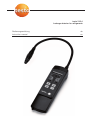
testo 316-4 Lecksuchgerät für Kältemittel Leakage detector for refrigerants Bedienungsanleitung Instruction manual de en 2 Sicherheit und Umwelt Sicherheit und Umwelt Zu diesem Dokument i Lesen Sie diese Dokumentation aufmerksam durch und machen Sie sich mit dem Produkt vertraut, bevor Sie es einsetzen. Bewahren Sie diese Dokumentation griffbereit auf, um bei Bedarf nachschlagen zu können. Geben Sie diese Dokumentation an spätere Nutzer des Produkts weiter. i Beachten Sie besonders die Informationen, welche durch folgende Zeichen hervorgehoben sind: · Mit Signalwort Warnung!: Warnt vor Gefahren, die zu schweren Körperverletzungen führen können, wenn die genannten Vorsichtsmaßnahmen nicht getroffen werden. · Mit Signalwort Vorsicht!: Warnt vor Gefahren, die zu leichten Körperverletzungen oder Sachschäden führen können, wenn die genannten Vorsichtsmaßnahmen nicht getroffen werden. · Wichtiger Hinweis. Personenschäden / Sachschäden vermeiden i Das Produkt nur sach- und bestimmungsgemäß und innerhalb der in den Technischen Daten vorgegebenen Parameter betreiben. Keine Gewalt anwenden. i Produkt bei Beschädigungen, Störungen und Fehlanzeigen überprüfen lassen. Fehlerhafte Geräte nicht mehr verwenden. i Mit dem Produkt nicht an oder in der Nähe von spannungsführenden Teilen messen. i Das Produkt nie zusammen mit Lösungsmitteln, Säuren oder anderen aggressiven Stoffen lagern. i Nur Wartungs- und Instandhaltungsarbeiten durchführen, die in der Dokumentation beschrieben sind. Dabei die vorgegebenen Handlungsschritte einhalten. Nur OriginalErsatzteile von Testo verwenden. Umwelt schützen i Defekte Akkus und leere Batterien an den dafür vorgesehenen Sammelstellen abgeben. i Produkt nach Ende der Nutzungszeit an Testo senden. Wir sorgen für eine umweltschonende Entsorgung. en Leistungsbeschreibung de Leistungsbeschreibung 3 Das testo 316-4 ist keine Schutzausrüstung! Verwenden Sie das testo 316-4 nicht als Überwachungsgerät für die persönliche Sicherheit! Weitere Gerätedaten · Betriebsbedingungen: -5...50°C/20...80%rF, mit eingeschränktem Funktionsumfang (nur akustische Anzeige, verringerte Genauigkeit, verringerte Betriebszeit) auch im Bereich -20...-5°C einsetzbar. · Lager-/Transportbedingungen: -25...70°C/20...80%rF · Minimaler Biegeradius Flexarm: 40 mm · Spannungsversorgung: Akkupack NiMh · · · · Batterie-Standzeit: ca. 6h (bei 22°C) Akku-Ladezeit: ca. 8h Abmessungen: 57 x 190 x 42mm Gewicht: 348g Richtlinien, Normen und Prüfungen · EG-Richtlinie: 2004/108/EG · Erfüllt SAE J1627 für Kältemittel R134a Garantie · Dauer: 2 Jahre · Garantiebedingungen: siehe Internetseite www.testo.com/warranty es it ?? · Sensor: Gassensitiver Halbleiter · Ansprechschwelle: <3g/a / <0.1oz/yr (spezifiziert für Referenz-Kältemittel) · Reaktionszeit: <1s ?? Messtechnische Daten nl Technische Daten pt · 0554 3180: Kältemittel-Sensorkopf für R134a, R22, R404a, H2 und weitere FCKW, HFKW, FKW · 0554 3181: NH3-Sensorkopf für Ammoniak. (Details siehe Tipps und Hilfe) sv Das testo 316-4 ist ein Lecksuchgerät für die schnelle und zuverlässige Detektion von Leckagen an Kälteanlagen und Wärmepumpen. Gaskonzentrationen werden optisch und akustisch angezeigt. Durch den wechselbaren Sensorkopf kann das Gerät an Ihre Anforderungen angepaßt werden: fr Funktionen und Verwendung 4 Produktbeschreibung Produktbeschreibung Auf einen Blick Sensorkopf mit Gassensor, wechselbar. Flexibles Sondenrohr. Stirnseite: Ohrhörer-Buchse, Netzteil-Buchse. Display. Bedientasten. Anzeige- und Bedienelemente Display Bedeutung Farbe der Displaybeleuchtung grün rot Kein Gas detektiert. Gas detektiert. Symbole Trend-Anzeige der Gaskonzentration: Kein Gas detektiert/Gas detektiert. Trend-Anzeige der Gaskonzentration: ErsteAlarmschwelle/Zweite Alarmschwelle. Maximalwert-Anzeige der Gaskonzentration (Schleppzeiger): Maximal detektierte Gaskonzentration seit dem letztem Rücksetzen des Schleppzeigers bzw. seit letztem Einschalten des Geräts. Zu detektierende Gasart. Lokalisierungsmodus. Batteriekapazität: Akku voll/Akku teilweise entladen/Restkapazität <15min. Akustische Anzeige: an/aus. Tasten Funktion Gerät: ein/aus. Zu detektierende Gasart: wählen. Akustische Anzeige: an/aus. Umschaltung Suchmodus/Lokalisierungsmodus. Taste gedrückt halten, bis 2 Pieptöne ertönen: Nullung . fr Die akustische Anzeige erfolgt über einen Signalton, dessen Taktfrequenz bei steigender Gaskonzentration steigt. Bei Überschreitung der zweiten Alamschwelle ertönt ein Dauerton. en Akustische Anzeige de Produktbeschreibung 5 it es Erste Schritte Für eine möglichst lange Akku-Lebensdauer sollte der Akku immer vollständig entladen und wieder aufgeladen werden. Der Betrieb des Gerätes während des Ladevorgangs ist möglich. 1 Landesspezifischen Stecker-Adapter auf den Netzstecker des Netzteils aufschieben und diesen an eine Netzsteckdose anschließen. 2 Gerätestecker des Netzteils an die Netzteil-Buchse des Geräts anschließen. - Der Ladevorgang startet: , und leuchten abwechselnd. - Ist der Akku geladen, stoppt der Ladevorgang automatisch: leuchtet. ² Ohrhörer verwenden: Nur die Original-Ohrhörer 0554 5001 verwenden! Bei gestecktem Ohrhörer ist der Geräte-Lautsprecher deaktiviert! i Anschlussstecker des Ohrhörers in die Ohrhörer-Buchse des Geräts stecken. nl ?? Der Akku kann nur bei einer Umgebungstemperatur von 0 bis +45°C geladen werden. Ist der Akku komplett entladen, beträgt die Ladezeit bei Raumtemperatur ca. 8h. ?? Nur das Original-Netzteil 0554 1093 verwenden! sv pt ² Akku laden: 6 Produkt verwenden Produkt verwenden ² Gerät einschalten: 1 drücken. - Alle Display-Segmente leuchten (Dauer: 3s), die Ansaugpumpe startet (Lüftergeräusch). - Die Initialisierungsphase (Aufheizen, Selbsttest) wird durchgeführt. Die benötigte Restzeit wird angezeigt. - Nach Abschluss der Initialisierungsphase: OK leuchtet (Dauer: 2s). Vorsicht! Verbrennungsgefahr durch heißen Sensorkopf nach längerer Betriebszeit! i Vor dem Anfassen des Sensorkopfes oder dem Verpacken des Geräts: Gerät ausschalten und Sensorkopf abkühlen lassen. ² Zu detektierende Gasart wählen (nur mit Sensorkopf 0554 3180): i mehrmals drücken, bis der Pfeil unter der gewünschten Gasart leuchtet. Für andere Gasarten bitte die Tabelle im Kapitel Tipps und Hilfe beachten. ² Nullung durchführen: i gedrückt halten, bis 2 Pieptöne ertönen. - Das Gerät wird auf die aktuelle Gaskonzentration normiert. ² Betriebsmodus wechseln: Nach dem Einschalten befindet sich das Geräte automatisch im Lokalisierungsmodus (Optimierung der Empfindlichkeit auf die Leckgröße). Bei Bedarf kann in den Suchmodus (Optimierung der Empfindlichkeit auf die Signaländerung) gewechselt werden. - drücken. erlischt. Der Suchmodus ist aktiviert. - erneut drücken. leuchtet im Display. Der Lokalisierungsmodus ist wieder aktiviert. i i Anzeige (Schleppzeiger) zurücksetzen: ² Maximalwert-A gedrückt halten, bis das Display erlischt. sv i nl ² Gerät ausschalten: pt gleichzeitig drücken. ?? und ?? i it i Den Sensorkopf möglichst nahe und mit geringer Geschwindigkeit (ca. 3 bis 5cm pro Sekunde) über die Bauteile führen, die auf Leckagen untersucht werden sollen. es fr Vorsicht! Zerstörung des Sensors durch nicht desorbierende Stoffe (z. B. Öle)! i Gerät nicht in verschmutzter Umgebung betreiben. en ² Gasdetektion (Lecksuche) durchführen: de Produkt verwenden 7 8 Produkt instand halten Produkt instand halten ± Akku laden: Siehe Kapitel „Erste Schritte“. ± Sensorkopf wechseln: Vorsicht! Verbrennungsgefahr durch heißen Sensorkopf nach längerer Betriebszeit! i Vor dem Anfassen des Sensorkopfes: Gerät ausschalten und Sensorkopf abkühlen lassen. 1 Schraubverschluss des Sensorkopfes öffnen und Sensorkopf vom Sondenrohr abziehen. 2 Neuen Sensorkopf auf das Sondenrohr stecken und den Schraubverschluss schließen. ± Sensor reinigen: Tabakqualm, schmutzige Luft, Öle, Fette und verdampfende Flüssigkeiten oder Gase können zu Ablagerungen auf der Sensoroberfläche führen. Mögliche Folgen sind reduzierte Empfindlichkeit, verfälschte Konzentrationsanzeigen oder Anzeige einer Untergrundkonzentration. Bei Bedarf den Sensor reinigen. i Gerät einschalten, Initalisierungsphase abwarten und ausschalten. Diesen Vorgang mehrmals wiederholen. ± Sensorkopf reinigen: i Sensorkopf bei Verschmutzung mit einem trockenen, weichen Tuch reinigen. ± Gehäuse reinigen: i Gehäuse bei Verschmutzung mit einem feuchten Tuch (Seifenlauge) reinigen. Keine scharfen Reinigungs- oder Lösungsmittel verwenden! ± Regelmäßige Überprüfung: Testo empfiehlt, eine jährliche Überprüfung des Gasspürgeräts durch eine autorisierte Servicestelle durchführen zu lassen. Tipps und Hilfe 9 en de Tipps und Hilfe Detektierbare Kältemittel Kältemittel Referenz KM Kältemittel Kältemittelauswahl Kältemittelgruppe (Untere Ansprechschwelle spezifiziert) detektierbar am Gerät x x x x R22 R22 R404a R22 R22 R22 R134a R404a R134a R22 R22 R134a R22 R134a R22 R22 H2 NH3 R22 R134a R134a R22 H2 R134a R404a R22 R22 R134a FCKW H-FCKW H-FKW R12 R22 R123 R134a R404 R407a, b, c, d, e R408 R409 R410a R505 R507 R600 R600a Wasserstoff Ammoniak R124 R227 R422d R11 R290 R508 R427a R1270 R1150 R170 x x x x x x x x x x x x x x x x x x x x x x x x ?? nl Falls wir Ihre Frage nicht beantworten konnten: Wenden Sie sich bitte an Ihren Händler oder den Testo-Kundendienst. Kontaktdaten siehe Rückseite dieses Dokuments oder Internetseite www.testo.com/service-contact. ?? “Error 03” “Error 04” “Sensor” blinkt it · Gerätefehler: Bitte kontaktieren Sie Ihren Händler oder den Testo-Kundendienst. · Sensor defekt (Drahtbruch): Bitte kontaktieren Sie Ihren Händler oder den TestoKundendienst. · Sensorverbindung gestört: Steckverbidnung des Sensorkopfes prüfen · Nicht zulässiger Sensorkopf: Sensorkopf wechseln. · Sensor verschmutzt: Sensor reinigen, siehe Kapitel „Produkt instand halten“. pt Mögliche Ursachen/Lösungen “Error 01” “Error 02” sv Frage es fr Fragen und Antworten 10 Tipps und Hilfe Zubehör und Ersatzteile Bezeichnung Kältemittel-Sensorkopf NH3-Sensorkopf Ohrhörer Netzteil Artikel-Nr. 0554 3180 0554 3181 0554 5001 0554 1093 Eine vollständige Liste aller Zubehör- und Ersatzteile finden Sie in den Produktkatalogen und -broschüren oder im Internet unter: www.testo.com testo 316-4 Leakage detector for refrigerants Bedienungsanleitung Instruction manual de en 12 Safety and environment Safety and environment On this document i Read this document through carefully, and familiarize yourself with the product before you put it to use. Keep this documentation close to hand in order to be able to consult it if required. Pass this documentation on to later users of the product. i Pay particular attention to information which is marked with the following symbols: · With the signal word Warning!: Warns of dangers which can lead to serious injury if the prescribed safety measures are not taken. · With the signal word Attention!: Warns of dangers which can lead to light injuries or material damage if the prescribed safety measures are not taken. · Important information Avoiding personal injury/material damage i Use the measuring instrument only for the purpose for which it is intended, and within the parameters stated in the technical data. Do not use force. i If damage, malfunction or incorrect display occur, have the instument checked. Do not use faulty instruments. i Do not carry out measurements with the product on or near live parts. i Never store the product together with solvents, acids or other corrosive substances. i Carry out only repair and maintenance work described in the instruction manual. Observe the prescribed handling steps. Use only original spare parts from Testo. Protecting the environment i Dispose of faulty rechargeable batteries/empty batteries at the proper collection points. i Send the product back to Testo at the end of its life. We will ensure that it is disposed of in an environmentally friendly manner. Specifications 13 en de Specifications Functions and application The testo 316-4 is not a piece of protective equipment! Do not use the testo 316-4 as a monitoring instrument for your personal safety! · · · · · Further instrument data Guidelines, norms and tests · Operating conditions: -5 to 50°C/23 to 122°F/20 to 80%RH, with limited functionality (only audible indication, reduced accuracy, reduced operating time) can also be used in the range -20°C to -5°C/-4 to 23°F · Storage/transp. conditions: -25 to 70°C/ -13 to 158°F/20 to 80%RH · Minimum bend radius gooseneck: 40 mm Current supply: Rech. battery pack NiMh Battery life: appprox. 6h (at 22°C/72°F) Charging time: approx. 8h Dimensions: 57 x 190 x 42mm Weight: 348g · EC guideline: 2004/108/EEC · Meets SAE J1627 for refrigerant R134a Warranty · Duration: 2 years · Warranty conditions: See web page www.testo.com/warranty ?? · Sensor: Gas-sensitive semi-conductor · Reaction threshold: <3g/a / <0.1oz/yr (specified for reference refrigerants) · Reaction time: <1s ?? Technical measuring data nl Technical data sv · 0554 3180: Refrigerant sensor head for R134a, R22, R404a, H2 and further CFC, HCFC, HFC · 0554 3181: NH3-sensor head for ammonia. (Details see Tips and assistance) pt The testo 316-4 is a leakage detection instrument for the fast and reliable detection of leakages on refrigeration systems and heat pumps. Gas concentrations are indicated optically and audibly. The instrument can be adapted to your requirements thanks to its exchangeable sensor head. 14 Product description Product description At a glance Sensor head with gas sensor, exchangeable. Flexible probe shaft. Top: earplug socket, mains unit socket. Display. Operating buttons. Display and operating elements Display Meaning Colour of the display illumination green red No gas detected. Gas detected. Symbols Gas concentration trend display: No gas detected / Gas detected. Gas concentration trend display: First alarm threshold / Second alarm threshold. Gas concentration maximum value display : Maximum gas concentration detected since the last reset of the maximum display or since the last time the instrument was switched on. Type of gas to be detected. Localization mode. Battery capacity: Battery full / battery partly discharged / remaining capacity <15min. Audible signal: on / off. Buttons Function Instrument: on / off. Type of gas to be detected: Select. Audible signal: on / off. Switch-over search mode / localization mode. Keep button pressed for 2s: Zeroing. fr The audible notification takes place with a signal tone whose interval frequency increases with increasing gas concentrations. A continuous signal sounds when the second alarm threshold is passed. en Audible notification de Product description 15 it es First steps In order to ensure as long a battery life as possible, the battery shoud always be completely discharged and recharged. The instrument can continue to be used during charging. 1 Plug the mains plug into the country-specific adapter and then plug into the mains socket. 2 Plug the instrument plug into the mains unit socket of the instrument. - Charging begins: , and light up alternately. - Charging stops automatically when the rechargeable battery is full: lights up. ² Using the earplug: Use only the original earplug 0554 5001! The instrument loudspeaker is deactivated when the earplug is plugged in! i Plug the connection plug of the earplug into the earplug socket of the instrument. nl ?? The rechargeable battery can only be charged at an ambient temperature of 0 to 45°C ( 32 to 113°F). If the rechargeable battery is completely discharged, charging takes approx. 8h. ?? Use only the original mains unit 0554 1093! sv pt ² Charging battery: 16 Using the product Using the product ² Switching on the instrument: 1 Press . - All display segments light up (duration: 3 sec), the suction pump starts (ventilator noise). - The initialization phase is carried out (heating, auto-test). The remaining duration is displayed. - After the end of the initialization phase: OK lights up (duration: 2 sec). Attention! Danger of burning from the hot sensor head after prolonged use! i Before touching the sensor head or packing up the instrument, switch off and allow to cool. ² Selecting gas to be detected (only with sensor head 0554 3180): i Press several times, until the arrow lights up under the desired gas type. For other gas types, please consult the table in the chapter Tips and assistance . ² Carrying out zeroing: i Keep pressed until two beep sounds are heard. - The instrument is standardised to the current gas concentration. ² Change operating mode: After switching on, the instrument is automatically in Localization mode (optimization of the sensitivity to the change in the signal). If required, Search mode can be activated (optimization of the sensitivity to the leakage quantity). i Press . disappears. Search mode is activated. i Press again. lights up in display. Localization mode is activated again. ² Carrying out gas detection: Attention! Destruction of the sensor by non-desorbant substances (e.g. oils)! i Do not use the instrument in dirty surroundings. i Move the sensor head as close as possible, and slowly (3 to 5 cm per second) over the parts which are to be examined for leaks. simultaneously. sv pt it es fr until the display switches off. nl i Press and hold ?? and ?? i Press ² Switching instrument off: en ² Resetting maximum value display: de Using the product 17 18 Tips and assistance Maintaining the product ± Charging the rechargeable battery: See chapter “First steps” ± Changing the sensor head: Attention! Danger of burning from the hot sensor head after prolonged use! i Before touching the measurement head or packing up the instrument, switch off and allow to cool. 1 Unscrew the sensor head and remove it from the probe shaft. 2 Plug the new sensor head on to the probe shaft and screw tight. ± Cleaning the sensor: Tobacco smoke, dirty air, oils, grease and evaporating liquids or gases can lead to deposits on the surface of the sensor. This can result in reduced sensitivity and falsified display of concentrations. If necessary clean the sensor. i Switch on the instrument, wait until the end of the initialization phase and switch off again. Repeat this procedure several times. ± Cleaning the sensor head: i If dirty, clean the sensor head with a soft dry cloth. ± Cleaning the housing: i If dirty, clean the housing with a damp cloth (soap solution). Do not use aggressive cleaning products or solvents! ± Regular servicing: Testo recommends yearly servicing of the gas detector by an authorized service centre. Tips and assistance 19 en de Tips and assistance Detectable refrigerants Refrigerant Reference refrigerant Detectable Refrigerant selection Refrigerant group (lower reaction threshold specified) refrigerant in instrument CFC HCFC HFC R12 R22 R123 R134a R404 R407a, b, c, d, e R408 R409 R410a R505 R507 R600 R600a Hydrogen Ammonia R124 R227 R422d R11 R290 R508 R427a R1270 R1150 R170 x x x x x x x x x x x x x x x x x x x x x x x x x x x x R22 R22 R404a R22 R22 R22 R134a R404a R134a R22 R22 R134a R22 R134a R22 R22 H2 NH3 R22 R134a R134a R22 H2 R134a R404a R22 R22 R134a ?? nl If we were not able to answer your question, please contact your dealer or Testo customer service. For contact data, see back of this document or web page www.testo.com/service-contact. ?? “Error 03” “Error 04” “Sensor” blinkt it · Instrument error: please contact your dealer or Testo customer service. · Sensor defective (wire breakage): please contact your dealer or Testo customer service. · Sensor connection incorrect: check plug connection of sensor head · Impermissible sensor head: change sensor head. · Sensor dirty: clean sensor, see chapter “Maintaining product”. pt Possible causes / solutions “Error 01” “Error 02” sv Question es fr Questions and answers 20 Tips and assistance Accessories and spare parts Description Refrigerant sensor head NH3 sensor head Earplug Mains unit A complete list of all accessories and spare parts can be found in the product catalogues and brochures or on the internet at: www.testo.com Part no. 0554 3180 0554 3181 0554 5001 0554 1093 en Appendix de Appendix 21 es it pt sv nl ?? ?? 1. The electric leak detector shall be operated in accordance with the equipment manufacturer`s operating instructions. 2. Leak test with the engine not in operation. 3. The air conditioning system shall be charged with sufficient refrigerant to have a gauge pressure of at least 340 kPa when not in operation. At temperatures below 15°C, leaks may not be measurable, since this pressure may not be reached. 4. Take care not to contaminate the detector probe tip if the part being tested is contaminated. If the part is particulary dirty, it should be wiped off with a dry shop towel or blown off with shop air. No cleaners or solvents shall be used, since many electronic detectors are sensitive to their ingredients. 5. Visually trace the entire refrigerant system, and look for signs of air-conditioning lubricant leakage, damage, and corrosion on all lines, hoses, and components. Each questionable area shall be carefully checked with the detector probe, as well as all fittings, hose to line couplings, refrigerant controls, service ports with caps in place, brazed or welded areas, and areas arround attachement points and hold-downs on lines and components. 6. Always follow the refrigerant system around in a continuous path so that no areas of potential leaks are missed. If a leak is found, always continue to test the reminder of the system. 7. At each area checked, the probe shall be moved around the location, at a rate no more than 25 to 50mm/s, and no more than 5mm from the surface completely around the position. Slower and closer movement or the probe greatly improves the likelihood of finding a leak. 8. An apparent leak shall be verified at least once by blowing shop air into the area of the suspected leak, if necessary, and repeating the check of the area. In cases of very large leaks, blowing out the area with shop air often helps locate the exact position of the leak. 9. Leak testing ot the evaporator core while in the air conditioning module shall be accomplished by turning the air conditioning blower on high for a period of 15s minimum, shutting it off, then waiting for the refrigerant to accumulate in the case for time specified by 9.1, then inserting the leak detector probe into the blower resistor block or condensate drain hole if no water is present, or into the closest opening in the heating/ventilation/air conditioning case to the evaporator, such as the heater duct or a vent duct. If the detector alarms, a leak apparently has been found. 9.1The accumulation time for evaporator testing is 10min. 10.Following any service to the refrigerant system of vehicle, and any other service which disturbs the refrigerant system, a leak test of the repair and of the service ports of the refrigerant system shall be done. fr Electronic Probe-Type Detector Instructions (according to SAE 1627)