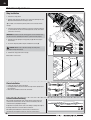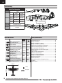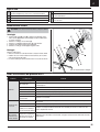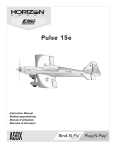
1
P-47 Thunderbolt Instruction Manual Bedienungsanleitung Manuel d’utilisation Manuale di Istruzioni EN NOTICE All instructions, warranties and other collateral documents are subject to change at the sole discretion of Horizon Hobby, LLC. For up-to-date product literature, visit www.horizonhobby.com and click on the support tab for this product. Meaning of Special Language: The following terms are used throughout the product literature to indicate various levels of potential harm when operating this product: NOTICE: Procedures, which if not properly followed, create a possibility of physical property damage AND little or no possibility of injury. CAUTION: Procedures, which if not properly followed, create the probability of physical property damage AND a possibility of serious injury. WARNING: Procedures, which if not properly followed, create the probability of property damage, collateral damage, and serious injury OR create a high probability of superficial injury. WARNING: Read the ENTIRE instruction manual to become familiar with the features of the product before operating. Failure to operate the product correctly can result in damage to the product, personal property and cause serious injury. This is a sophisticated hobby product. It must be operated with caution and common sense and requires some basic mechanical ability. Failure to operate this Product in a safe and responsible manner could result in injury or damage to the product or other property. This product is not intended for use by children without direct adult supervision. Do not use with incompatible components or alter this product in any way outside of the instructions provided by Horizon Hobby, LLC. This manual contains instructions for safety, operation and maintenance. It is essential to read and follow all the instructions and warnings in the manual, prior to assembly, setup or use, in order to operate correctly and avoid damage or serious injury. 14+ AGE RECOMMENDATION: Not for children under 14 years. This is not a toy. WARNING AGAINST COUNTERFEIT PRODUCTS: If you ever need to replace your Spektrum receiver found in a Horizon Hobby product, always purchase from Horizon Hobby, LLC or a Horizon Hobby authorized dealer to ensure authentic high-quality Spektrum product. Horizon Hobby, LLC disclaims all support and warranty with regards, but not limited to, compatibility and performance of counterfeit products or products claiming compatibility with DSM or Spektrum. Safety Precautions and Warnings As the user of this product, you are solely responsible for operating in a manner that does not endanger yourself and others or result in damage to the product or the property of others. • Always keep a safe distance in all directions around your model to avoid collisions or injury. This model is controlled by a radio signal subject to interference from many sources outside your control. Interference can cause momentary loss of control. • Always operate your model in open spaces away from full-size vehicles, traffic and people. • Always carefully follow the directions and warnings for this and any optional support equipment (chargers, rechargeable battery packs, etc.). • Always keep all chemicals, small parts and anything electrical out of the reach of children. • Always avoid water exposure to all equipment not specifically designed and protected for this purpose. Moisture causes damage to electronics. • Never place any portion of the model in your mouth as it could cause serious injury or even death. • Never operate your model with low transmitter batteries. • Always keep aircraft in sight and under control. • Always use fully charged batteries. • Always keep transmitter powered on while aircraft is powered. • Always remove batteries before disassembly. • Always keep moving parts clean. • Always keep parts dry. • Always let parts cool after use before touching. • Always remove batteries after use. • Always ensure failsafe is properly set before flying. • Never operate aircraft with damaged wiring. • Never touch moving parts. Charging Warnings CAUTION: All instructions and warnings must be followed exactly. Mishandling of Li-Po batteries can result in a fire, personal injury, and/or property damage. • Never leave charging batteries unattended. • Never charge batteries overnight. • By handling, charging or using the included Li-Po battery, you assume all risks associated with lithium batteries. • If at any time the battery begins to balloon or swell, discontinue use immediately. If charging or discharging, discontinue and disconnect. Continuing to use, charge or discharge a battery that is ballooning or swelling can result in fire. • Always store the battery at room temperature in a dry area for best results. • Always transport or temporarily store the battery in a temperature range of 40–120º F (5–49º C). Do not store battery or aircraft in a car or direct sunlight. If stored in a hot car, the battery can be damaged or even catch fire. • Always charge batteries away from flammable materials. • Always inspect the battery before charging and never charge dead or damaged batteries. • Always disconnect the battery after charging, and let the charger cool between charges. • Always constantly monitor the temperature of the battery pack while charging. • ONLY USE A CHARGER SPECIFICALLY DESIGNED TO CHARGE LI-PO BATTERIES. Failure to charge the battery with a compatible charger may cause fire resulting in personal injury and/or property damage. • Never discharge Li-Po cells to below 3V under load. • Never cover warning labels with hook and loop strips. • Never charge batteries outside recommended levels. • Never attempt to dismantle or alter the charger. • Never allow minors under the age of 14 to charge battery packs. • Never charge batteries in extremely hot or cold places (recommended between 40–120° F or 5–49° C) or place in direct sunlight. To register your product online, visit www.e-fliterc.com 2 EN Box Contents Quick Start Information Transmitter Setup Set up your transmitter using the transmitter setup chart Hi Rate Low Rate Rud =11mm =11mm =12mm =12mm =20mm =20mm =07mm =07mm =8mm =8mm =15mm =15mm Flaps =25mm Ail Dual Rates Ele Full Takeoff =15mm Center of Gravity (CG) 60mm back from leading edge at the root. Flight Timer Setting 5-7 minutes Specifications Motor: BL15 Brushless Outrunner Motor, 950Kv (PKZ5116) ESC: E-flite 30-Amp Pro Brushless ESC (EFLA1030B) 2) Aileron Servos (1) Rudder Servo (PKZ1081) (1) Elevator Servo (2) Flap Servos (PKZ1090) Receiver: Spektrum™ AR636A 6-Channel Sport Receiver (SMPAR636) Recommended Battery: 11.1V 3S 2200mAh 30C Li-Po (EFLB22003S30) Recommended Battery Charger: 3-cell Li-Po battery balancing charger Recommended Transmitter: Full-Range 6 channel (or more) 2.4GHz with Spektrum DSM2®/DSMX® technology with adjustable Dual Rates. TTable of Contents Installed Installed Installed Installed Installed Installed Required to Complete Required to Complete Required to Complete Required to Complete Required to Complete Required to Complete Required to Complete Installed 36.9 in (940mm) 42.2 in (1070mm) 44.7 oz (1268 g) Preflight ..........................................................................................4 Transmitter Setup ..........................................................................4 Model Assembly .............................................................................5 Model Assembly Continued .............................................................6 Model Assembly Continued .............................................................7 Control Horn and Servo Arm Settings ..............................................7 PNP Receiver Selection and Installation ..........................................8 Transmitter and Receiver Binding....................................................8 Battery Installation and ESC Arming ................................................9 Center of Gravity (CG) ..................................................................10 AS3X Control Direction Test .........................................................10 Flying Tips and Repairs .................................................................11 Post Flight ....................................................................................12 Motor Service ...............................................................................12 Troubleshooting Guide AS3X .........................................................12 Troubleshooting Guide ..................................................................13 AMA National Model Aircraft Safety Code ......................................14 Limited Warranty ..........................................................................15 Contact Information ......................................................................16 FCC Information ............................................................................16 IC Information ...............................................................................16 Compliance Information for the European Union ............................16 Replacement Parts........................................................................58 Optional Parts ...............................................................................59 326 sq in (21.0 sq dm) 3 EN Preflight 1 Remove and inspect contents. 10 Test the retract operation. 2 Read this instruction manual thoroughly. 11 Test the flap operation. 3 Charge the flight battery. 12 Perform the Control Direction Test with the transmitter. 4 Setup Transmitter using transmitter setup chart. 13 Perform the AS3X Control Direction Test with the aircraft. 5 Fully assemble the airplane. 14 Adjust flight controls and transmitter. 6 Install the flight battery in the aircraft (once it has been fully charged). 15 Perform a radio system Range Test. 7 Check the Center of Gravity (CG). 16 Find a safe open area to fly. 8 Bind the aircraft to your transmitter. 17 Plan flight for flying field conditions. 9 Make sure linkages move freely. Transmitter Setup IMPORTANT: After you set up your model, always rebind the transmitter and receiver to set the desired failsafe positions. Dual Rates Take first flights in Low Rate. For landings, use high rate elevator. NOTICE: To ensure AS3X functions properly, do not lower rate values below 50%. If lower rates are desired, manually adjust the position of the pushrods on the servo arm. NOTICE: If oscillation occurs at high speed, refer to the Troubleshooting Guide for more information. Expo Expo is factory set in the receiver. After first flights, you may adjust expo in your transmitter or refer to the AR636 receiver manual for expo adjustment. 4 Computerized Transmitter Setup (DX6i, DX6, DX7, DX7S, DX8, DX9, DX10t and DX18) Start all transmitter programming with a blank ACRO model (do a model reset), then name the model. HIGH 100% Set Dual Rates to: LOW 70% Set Servo Travel to: 100% 1. Go to the SETUP LIST MENU 2. Set MODEL TYPE: ACRO 3. Set REVERSE: Gear Channel DX6i 4. Go to ADJUST LIST MENU 5. Set FLAPS: Norm 100 Flap and 0 ELEV LAND 80 Flap and 10 ELEV 1. Go to the SYSTEM SETUP 2. Set MODEL TYPE: AIRPLANE 3. Set WING TYPE: 1 AIL 1 FLAP 4. Go to the FUNCTION LIST DX7S 5. Set SERVO SETUP: Reverse GEAR 6. Set FLAP SYSTEM: Choose Flap DX8 NORM: -100% FLAP and 0% ELEV MID: -30% FLAP and -3% ELEV LAND: 80% FLAP and -10% ELEV SPEED 2.0S: SWITCH = FLAP 1. Go to the SYSTEM SETUP 2. Set MODEL TYPE: AIRPLANE 3. Set AICRAFT TYPE: WING: 1 AIL 1 FLAP DX6 4. Go to the FUNCTION LIST DX7 5. Set SERVO SETUP: Reverse GEAR DX9 6. Set FLAP SYSTEM: DX10t SELECT SWITCH D: DX18 POS 0: -100% FLAP and 0% ELEV POS 1: -30% FLAP and -3% ELEV POS 2: 80% FLAP and -10% ELEV SPEED 2.0 EN Model Assembly Propeller Installation B IMPORTANT: It is recommended to install the propeller after all system setups are completed to reduce the chance of accidental propeller strike. 1. Use a tool to remove the spinner (A) from the collet (B). 2. Install the propeller with the size numbers (9.8 x 6) facing out from the motor. 3. Use a tool to re-install the spinner and secure the propeller in place. A Horizontal Tail Installation 1. Slide the horizontal tail tube (A) into the hole in the rear of the fuselage. 2. Install the 2 piece (left and right) horizontal tail as shown. Ensure the control horn faces down. 3. Apply 4 pieces of tape (B) (included) to secure the two horizontal tail pieces in place. A 4. Attach the clevis to the elevator control horn (see instructions for clevis connection). B 5 EN Model Assembly Continued Wing Installation 1. Remove the canopy hatch. 2. Guide the Flaps, Retracts and Aileron servo connectors (A) through the hole (B) located in the bottom of the fuselage as shown. Tip: If needed, use hemostats or pliers to pull the servo connectors into the fuselage. C 3. Connect the Flaps, Retracts and Aileron connectors to respective Y-harnesses connected to the receiver. The left and right servos can be connected to either side of a Y-harness. IMPORTANT: The ailerons must be connected to the receiver’s AILE (#2 channel) with a Y-harness (included) for the AS3X@ system to function properly. B A 4. Mount the wing by aligning the wing’s guide pins (C) with the fuselage’s bracket holes. 5. Secure the wing into position using the included three screws (D). Flaps CAUTION: DO NOT crush or otherwise damage the wiring when attaching the wing to the fuselage. Gear Ailerons 6. Reinstall the canopy hatch on the fuselage. Disassemble in reverse order. D Clevis Installation 1. 4. • Pull the tube from the clevis to the linkage. • Carefully spread the clevis, then insert the clevis pin into the desired hole in the control horn. • Move the tube to hold the clevis on the control horn. 2. 5. 3. 6. Control Surface Centering After assembly and transmitter setup, confirm that the control surfaces are centered. If the control surfaces are not centered, mechanically center the control surfaces by adjusting the linkages. If adjustment is required, turn the clevis on the linkage to change the length of the linkage between the servo arm and the control horn. After binding a transmitter to the aircraft receiver, set the trims and sub-trims to 0, then adjust the clevises to center the control surfaces. 6 EN Model Assembly Continued Optional Belly Skid Installation Attach the clear plastic belly skid to the bottom of the fuselage using doublesided tape as shown. The belly skid is recommended if flying without landing gear. Control Horn and Servo Arm Settings The table to the right shows the factory settings for the control horns and servo arms. Fly the aircraft at factory settings before making changes. NOTICE: If control throws are changed from the factory settings, the AR636 gain values may need to be adjusted. Refer to the Spektrum AR636 manual for adjustment of gain values. After flying, you may choose to adjust the linkage positions for the desired control response. See the table to the right. Horns Arms Elevator Ailerons Flaps Rudder Tail Wheel More control throw Less control throw 7 EN PNP Receiver Selection and Installation The Spektrum AR636 receiver is recommended for ths airplane. If you choose to install another receiver, ensure that it is at least a 6-channel full range (sport) receiver. Refer to your receiver manual for correct installation and operation instructions. Installation (AR636 shown) 1. Remove the canopy hatch from the fuselage. 2. Mount the receiver parallel to the length of the fuselage as shown. Use double-sided servo tape. 1 = Throttle 2 = Aileron 3 = Elevator 4 = Rudder 5 = Gear 6 = Flaps CAUTION: Incorrect installation of the receiver could cause incorrect AS3X orientation, which could result in a crash. 3. Attach the appropriate control surfaces to the their respective ports on the receiver using the chart in the illustration. Transmitter and Receiver Binding Binding is the process of programming the receiver to recognize the GUID (Globally Unique Identifier) code of a single specific transmitter. You need to ‘bind’ your chosen Spektrum™ DSM2®/DSMX® technology equipped aircraft transmitter to the receiver for proper operation. IMPORTANT: Before binding a transmitter, read the Transmitter Setup section of this manual to ensure that your transmitter is properly programmed for this aircraft. Binding Procedure IMPORTANT: The included AR636 receiver has been programmed for operation specifically for this aircraft. Refer to the receiver manual for correct setup if the receiver is replaced or is used in another aircraft. Read the transmitter instructions for binding to a receiver (location of transmitter’s Bind control). Please visit www.bindnfly.com for a complete list of compatible transmitters. CAUTION: When using a Futaba® transmitter with a Spektrum DSM module, you must reverse the throttle channel and rebind. Refer to your Spektrum module manual for binding and failsafe instructions. Refer to your Futaba transmitter manual for instructions on reversing the throttle channel. 8 1. Make sure the transmitter is powered off. 2. Move the transmitter controls to neutral (flight controls: rudder, elevators and ailerons) or to low positions (throttle, throttle trim).** 3. Install a bind plug in the receiver bind port. 4. Connect the flight battery to the ESC. The ESC will produce a series of sounds. One long tone, then 3 short tones confirm that the LVC is set correctly for the ESC. The orange bind LED on the receiver will begin to flash rapidly. 5. Power on the transmitter while holding the transmitter bind button or switch. Refer to your transmitter’s manual for binding. 6. When the receiver binds to the transmitter, the orange bind light on the receiver will turn solid and the ESC will produce a series of three ascending tones. The tones indicate the ESC is armed, provided the throttle stick and throttle trim are low enough to trigger arming. 7. Remove the bind plug from the bind port. 8. Safely store the bind plug (some owners attach the bind plug to their transmitter using two-part loops and clips). 9. The receiver should retain the binding instructions received from the transmitter until another binding is done. * The throttle will not arm if the transmitter’s throttle control is not put at the lowest position. If you encounter problems, follow the binding instructions and refer to the transmitter troubleshooting guide for other instructions. If needed, contact the appropriate Horizon Product Support office. **Failsafe If the receiver loses transmitter communication, the failsafe will activate. When activated, the airplane controls return to the neutral position established during step 2 of the binding procedure. Bind Plug Installation BIND PLUG EN Battery Installation and ESC Arming Battery Selection A We recommend the E-flite® 2200mAh 11.1V 3S 30C Li-Po battery (EFLB22003S30). Refer to the Optional Parts List for other recommended batteries. If using a battery other than those listed, the battery should be within the range of capacity, dimensions and weight of the E-flite Li-Po battery packs to fit in the fuselage. Be sure the model balances at the recommended CG. 1. Lower the throttle and throttle trim to the lowest settings. Power on the Transmitter, then wait 5 seconds. 2. Apply the loop side (soft side) of the hook and loop tape (A) to the bottom of your battery. 3. Carefully lift the back of the canopy hatch (B) to remove. B 4. Install the fully charged battery (C) in the battery compartment as shown. See the Adjusting the Center of Gravity instructions for more information. 5. Make sure the flight battery is secured using the hook and loop strap (D). 6. Connect the battery to the ESC (the ESC is now armed). 7. Keep the aircraft immobile and away from wind or the system will not initialize. • The ESC will sound a series of tones (refer to step 6 of the binding instructions for more information). • An LED will light on the receiver. If the ESC sounds a continuous double beep after the flight battery is connected, recharge or replace the battery. 8. Reinstall the canopy hatch. D C CAUTION: Always keep hands away from the propeller. When armed, the motor will turn the propeller in response to any throttle movement. 9 EN Center of Gravity (CG) The CG location is measured from the leading edge of the wing at the root. This CG location has been determined with the recommended Li-Po battery (EFLB22003S30) installed all the way forward in the battery compartment. 60mm back from leading edge at the root. AS3X Control Direction Test This test ensures that the AS3X® control system is functioning properly. Assemble the aircraft and bind your transmitter to the receiver before performing this test. Aircraft movement IMPORTANT: The AR636 programming for this aircraft increases control surface movement when flaps are fully down. 2. Move the entire aircraft as shown and ensure the control surfaces move in the direction indicated in the graphic. If the control surfaces do not respond as shown, do not fly the aircraft. Refer to the receiver manual for more information. Rudder Once the AS3X system is active, control surfaces may move rapidly. This is normal. AS3X remains active until the battery is disconnected. Aileron CAUTION: Keep all body parts, hair and loose clothing away from a moving propeller, as these items could become entangled. Elevator 1. Raise the throttle just above 25%, then lower the throttle to activate AS3X. 10 AS3X Reaction EN Flying Tips and Repairs Consult local laws and ordinances before choosing a flying location. Range Check your Radio System Before you fly, range check the radio system. Refer to your specific transmitter instruction manual for range test information. Oscillation Once the AS3X system is active (after advancing the throttle for the first time), you will normally see the control surfaces react to aircraft movement. In some flight conditions you may see oscillation (the aircraft rocks back and forth on one axis due to overcontrol). If oscillation occurs, refer to the Troubleshooting Guide for more information. Takeoff Place the aircraft facing into the wind. Set your transmitter in low rate and use your flaps switch to drop the flaps to takeoff or “half position”. Gradually increase the throttle to ¾ and steer with the rudder. Flaps make takeoffs shorter. As the tail comes off the ground, pull back gently on the elevator. When airborn, flip your gear switch to raise your landing gear. Climb to a comfortable altitude and then flip your flaps switch to level the flaps. Flying During your first flight, trim the aircraft for level flight at 3/4 throttle. Make small trim adjustments with your transmitter’s trim switches to straighten the aircraft’s flight path. After adjusting transmitter trim in the air, do not touch the control sticks for 5 seconds. This allows the receiver to learn the correct settings to optimize AS3X performance. Failure to do so could affect flight performance. Keep the throttle on until the aircraft is ready to flare. During flare, keep the wings level and the aircraft pointed into the wind. Gently lower the throttle while pulling back on the elevator to bring the aircraft down on the front wheels (two point landing). The aircraft can also be landed on all three wheels (three point landing). When the aircraft touches down, reduce back pressure on the elevator stick to keep the aircraft from becoming airborn again. If landing on grass, it is best to hold full up elevator after touchdown and when taxiing to prevent nosing over. Once on the ground, avoid sharp turns until the plane has slowed enough to prevent scraping the wingtips. NOTICE: If a crash is imminent, reduce the throttle and trim fully. Failure to do so could result in extra damage to the airframe, as well as damage to the ESC and motor. WARNING: Always decrease throttle at propeller strike. NOTICE: After any impact, always ensure the receiver is secure in the fuselage. If you replace the receiver, install the new receiver in the same orientation as the original receiver or damage may result. NOTICE: Crash damage is not covered under warranty. NOTICE: When you are finished flying, never leave the 5 Seconds aircraft in direct sunlight or in a hot, enclosed area Tip: If using more than 8 clicks of flight trim, mechanically adjust the linkage so less trim is needed, or AS3X operation may be affected. After landing, adjust the linkages mechanically to account for trim changes and then reset the trims to neutral. Ensure the aircraft will fly straight and level with no trim or sub-trim. Landing For your first flights with the recommended battery pack (EFLB22003S30), set your transmitter timer or a stopwatch to 5 minutes. After five minutes, land the aircraft. Adjust your timer for longer or shorter flights once you have flown the model. If at any time the motor pulses, land the aircraft immediately to recharge the flight battery. See the Low Voltage Cutoff (LVC) section for more details on maximizing battery health and run time. Land the aircraft into the wind. Use high rate Elevator for landings. Use a small amount of throttle for the entire descent. Lower the throttle to ¼ and flip your flaps switch to deploy the flaps to the landing or “full down position”. Flaps will make the landing approach steeper and slower, and allow for a smoother landing. Flip your gear switch to lower your landing gear. This will slow the aircraft further. such as a car. Doing so can damage the aircraft. Low Voltage Cutoff (LVC) When a Li-Po battery is discharged below 3V per cell, it will not hold a charge. The ESC protects the flight battery from over-discharge using Low Voltage Cutoff (LVC). Before the battery charge decreases too much, LVC removes power supplied to the motor. Power to the motor pulses, showing that some battery power is reserved for flight control and safe landing. Disconnect and remove the Li-Po battery from the aircraft after use to prevent trickle discharge. Charge your Li-Po battery to about half capacity before storage. During storage, make sure the battery charge does not fall below 3V per cell. LVC does not prevent the battery from over-discharge during storage. NOTICE: Repeated flying to LVC will damage the battery. Tip: Monitor your aircraft battery’s voltage before and after flying by using a Li-Po Cell Voltage Checker (EFLA111, sold separately). Repairs Thanks to the Z-Foam™ material in this aircraft, repairs to the foam can be made using virtually any adhesive (hot glue, regular CA, epoxy, etc). When parts are not repairable, see the Replacement Parts List for ordering by item number. For a listing of all replacement and optional parts, refer to the list at the end of this manual. NOTICE: Use of CA accelerant on your aircraft can damage paint. DO NOT handle the aircraft until accelerant fully dries. 11 EN Post Flight 1 Disconnect the flight battery from the ESC (Required for Safety and battery life). 5 Repair or replace all damaged parts. 2 Power OFF the transmitter. 6 Store the flight battery apart from the aircraft and monitor the battery charge. 3 Remove the flight battery from the aircraft. 7 4 Recharge the flight battery. Make note of the flight conditions and flight plan results, planning for future flights. Motor Service CAUTION: Always disconnect the flight battery before performing motor service. H I Disassembly E 1. Remove the spinner nut (A), propeller (B), backplate (C) and collet (D) from the motor shaft (E). A tool is required to remove the spinner nut. 2 3. 4. 5. Remove the 4 screws (F) and cowling (G). Remove the 4 screws (H) from the motor mount (I) and the fuselage. Disconnect the motor wires from the ESC wires. Remove the 4 screws (J) and motor (K) from the motor mount. D C J B Assembly K Assemble in reverse order. • Correctly align and connect the motor wire colors with the ESC wires. • Install the propeller with the size numbers (9.8 x 6) facing out from the motor. • A tool is required to tighten the lock nut on the collet. F A G Not all wiring shown. Troubleshooting Guide AS3X Problem Possible Cause Solution Damaged propeller or spinner Replace propeller or spinner Imbalanced propeller Balance the propeller. For more information, view John Redman’s propeller balancing video at www. horizonhobby.com Motor vibration Replace parts or correctly align all parts and tighten fasteners as needed Loose receiver Align and secure receiver in fuselage Loose aircraft controls Tighten or otherwise secure parts (servo, arm, linkage, horn and control surface) Worn parts Replace worn parts (especially propeller, spinner or servo) Irregular servo movement Replace servo Trim is not at neutral If you adjust trim more than 8 clicks, adjust the clevis to remove trim Sub-Trim is not at neutral No Sub-Trim is allowed. Adjust the servo linkage Aircraft was not kept immobile for 5 seconds after battery connection. With the throttle stick in lowest position. Disconnect battery, then reconnect battery and keep the aircraft still for 5 seconds Incorrect direction settings in the receiver, which can cause a crash DO NOT fly. Correct the direction settings (refer to the receiver manual), then fly Oscillation Inconsistent flight performance Incorrect response to the AS3X Control Direction Test 12 EN Troubleshooting Guide Problem Aircraft will not respond to throttle but responds to other controls Extra propeller noise or extra vibration Reduced flight time or aircraft underpowered Aircraft will not Bind (during binding) to transmitter Aircraft will not connect (after binding) to transmitter Possible Cause Throttle not at idle and/or throttle trim too high Reset controls with throttle stick and throttle trim at lowest setting Throttle servo travel is lower than 100% Make sure throttle servo travel is 100% or greater Throttle channel is reversed Reverse throttle channel on transmitter Motor disconnected from ESC Make sure motor is connected to the ESC Damaged propeller and spinner, collet or motor Replace damaged parts Propeller is out of balance Balance or replace propeller Prop nut is too loose Tighten the prop nut Flight battery charge is low Completely recharge flight battery Propeller installed backwards Install propeller with numbers facing forward Flight battery damaged Replace flight battery and follow flight battery instructions Flight conditions may be too cold Make sure battery is warm before use Battery capacity too low for flight conditions Replace battery or use a larger capacity battery Transmitter too near aircraft during binding process Move powered transmitter a few feet from aircraft, disconnect and reconnect flight battery to aircraft Aircraft or transmitter is too close to large metal object, wireless source or another transmitter Move aircraft and transmitter to another location and attempt binding again The bind plug is not installed correctly in the bind port Install bind plug in bind port and bind the aircraft to the transmitter Flight battery/transmitter battery charge is too low Replace/recharge batteries Bind switch or button not held long enough during bind process Power off transmitter and repeat bind process. Hold transmitter bind button or switch until receiver is bound Transmitter too near aircraft during connecting process Move powered transmitter a few feet from aircraft, disconnect and reconnect flight battery to aircraft Aircraft or transmitter is too close to large metal object, wireless source or another transmitter Move aircraft and transmitter to another location and attempt connecting again Bind plug left installed in bind port Rebind transmitter to the aircraft and remove the bind plug before cycling power Aircraft bound to different model memory (ModelMatchTM radios only) Select correct model memory on transmitter Flight battery/Transmitter battery charge is too low Replace/recharge batteries Transmitter may have been bound to a different aircraft using different DSM protocol Bind aircraft to transmitter Control surface, control horn, linkage or servo damage Replace or repair damaged parts and adjust controls Wire damaged or connections loose Do a check of wires and connections, connect or replace as needed Control surface does Transmitter is not bound correctly or the incorrect not move airplanes was selected Controls reversed Motor power pulses then motor loses power Solution Re-bind or select correct airplanes in transmitter Flight battery charge is low Fully recharge flight battery BEC (Battery Elimination Circuit) of the ESC is damaged Replace ESC Transmitter settings are reversed Perform the Control Direction Test and adjust the controls on transmitter appropriately ESC uses default soft Low Voltage Cutoff (LVC) Recharge flight battery or replace battery that is no longer performing Weather conditions might be too cold Postpone flight until weather is warmer Battery is old, worn out, or damaged Replace battery Battery C rating might be too small Use recommended battery 13 EN AMA National Model Aircraft Safety Code Effective January 1, 2014 A. GENERAL A model aircraft is a non-human-carrying aircraft capable of sustained flight in the atmosphere. It may not exceed limitations of this code and is intended exclusively for sport, recreation, education and/or competition. All model flights must be conducted in accordance with this safety code and any additional rules specific to the flying site. 1. Model aircraft will not be flown: (a) In a careless or reckless manner. (b) At a location where model aircraft activities are prohibited. 2. Model aircraft pilots will: (a) Yield the right of way to all man carrying aircraft. (b) See and avoid all aircraft and a spotter must be used when appropriate. (AMA Document #540-D.) (c) Not fly higher than approximately 400 feet above ground level within three (3) miles of an airport, without notifying the airport operator. (d) Not interfere with operations and traffic patterns at any airport, heliport or seaplane base except where there is a mixed use agreement. (e) Not exceed a takeoff weight, including fuel, of 55 pounds unless in compliance with the AMA Large Model Aircraft program. (AMA Document 520-A.) (f) Ensure the aircraft is identified with the name and address or AMA number of the owner on the inside or affixed to the outside of the model aircraft. (This does not apply to model aircraft flown indoors). (g) Not operate aircraft with metal-blade propellers or with gaseous boosts except for helicopters operated under the provisions of AMA Document #555. (h) Not operate model aircraft while under the influence of alcohol or while using any drug which could adversely affect the pilot’s ability to safely control the model. (i) Not operate model aircraft carrying pyrotechnic devices which explode or burn, or any device which propels a projectile or drops any object that creates a hazard to persons or property. Exceptions: • Free Flight fuses or devices that burn producing smoke and are securely attached to the model aircraft during flight. • Rocket motors (using solid propellant) up to a G-series size may be used provided they remain attached to the model during flight. Model rockets may be flown in accordance with the National Model Rocketry Safety Code but may not be launched from model aircraft. • Officially designated AMA Air Show Teams (AST) are authorized to use devices and practices as defined within the Team AMA Program Document (AMA Document #718). (j) Not operate a turbine-powered aircraft, unless in compliance with the AMA turbine regulations. (AMA Document #510-A). 3. Model aircraft will not be flown in AMA sanctioned events, air shows or model demonstrations unless: (a) The aircraft, control system and pilot skills have successfully demonstrated all maneuvers intended or anticipated prior to the specific event. (b) An inexperienced pilot is assisted by an experienced pilot. 4. When and where required by rule, helmets must be properly worn and fastened. They must be OSHA, DOT, ANSI, SNELL or NOCSAE approved or comply with comparable standards. 14 B. RADIO CONTROL 1. All pilots shall avoid flying directly over unprotected people, vessels, vehicles or structures and shall avoid endangerment of life and property of others. 2. A successful radio equipment ground-range check in accordance with manufacturer’s recommendations will be completed before the first flight of a new or repaired model aircraft. 3. At all flying sites a safety line(s) must be established in front of which all flying takes place (AMA Document #706.) (a) Only personnel associated with flying the model aircraft are allowed at or in front of the safety line. (b) At air shows or demonstrations, a straight safety line must be established. (c) An area away from the safety line must be maintained for spectators. (d) Intentional flying behind the safety line is prohibited. 4. RC model aircraft must use the radio-control frequencies currently allowed by the Federal Communications Commission (FCC). Only individuals properly licensed by the FCC are authorized to operate equipment on Amateur Band frequencies. 5. RC model aircraft will not operate within three (3) miles of any pre-existing flying site without a frequency-management agreement (AMA Documents #922 and #923.) 6. With the exception of events flown under official AMA Competition Regulations, excluding takeoff and landing, no powered model may be flown outdoors closer than 25 feet to any individual, except for the pilot and the pilot’s helper(s) located at the flight line. 7. Under no circumstances may a pilot or other person touch a model aircraft in flight while it is still under power, except to divert it from striking an individual. 8. RC night flying requires a lighting system providing the pilot with a clear view of the model’s attitude and orientation at all times. Hand-held illumination systems are inadequate for night flying operations. 9. The pilot of a RC model aircraft shall: (a) Maintain control during the entire flight, maintaining visual contact without enhancement other than by corrective lenses prescribed for the pilot. (b) Fly using the assistance of a camera or First-Person View (FPV) only in accordance with the procedures outlined in AMA Document #550. (C) Fly using the assistance of autopilot or stabilization system only in accordance with the procedures outlined in AMA Document #560. Please see your local or regional modeling association’s guidelines for proper, safe operation of your model aircraft. EN Limited Warranty What this Warranty Covers Horizon Hobby, LLC, (Horizon) warrants to the original purchaser that the product purchased (the “Product”) will be free from defects in materials and workmanship at the date of purchase. What is Not Covered This warranty is not transferable and does not cover (i) cosmetic damage, (ii) damage due to acts of God, accident, misuse, abuse, negligence, commercial use, or due to improper use, installation, operation or maintenance, (iii) modification of or to any part of the Product, (iv) attempted service by anyone other than a Horizon Hobby authorized service center, (v) Product not purchased from an authorized Horizon dealer, or (vi) Product not compliant with applicable technical regulations. OTHER THAN THE EXPRESS WARRANTY ABOVE, HORIZON MAKES NO OTHER WARRANTY OR REPRESENTATION, AND HEREBY DISCLAIMS ANY AND ALL IMPLIED WARRANTIES, INCLUDING, WITHOUT LIMITATION, THE IMPLIED WARRANTIES OF NON-INFRINGEMENT, MERCHANTABILITY AND FITNESS FOR A PARTICULAR PURPOSE. THE PURCHASER ACKNOWLEDGES THAT THEY ALONE HAVE DETERMINED THAT THE PRODUCT WILL SUITABLY MEET THE REQUIREMENTS OF THE PURCHASER’S INTENDED USE. Purchaser’s Remedy Horizon’s sole obligation and purchaser’s sole and exclusive remedy shall be that Horizon will, at its option, either (i) service, or (ii) replace, any Product determined by Horizon to be defective. Horizon reserves the right to inspect any and all Product(s) involved in a warranty claim. Service or replacement decisions are at the sole discretion of Horizon. Proof of purchase is required for all warranty claims. SERVICE OR REPLACEMENT AS PROVIDED UNDER THIS WARRANTY IS THE PURCHASER’S SOLE AND EXCLUSIVE REMEDY. Limitation of Liability HORIZON SHALL NOT BE LIABLE FOR SPECIAL, INDIRECT, INCIDENTAL OR CONSEQUENTIAL DAMAGES, LOSS OF PROFITS OR PRODUCTION OR COMMERCIAL LOSS IN ANY WAY, REGARDLESS OF WHETHER SUCH CLAIM IS BASED IN CONTRACT, WARRANTY, TORT, NEGLIGENCE, STRICT LIABILITY OR ANY OTHER THEORY OF LIABILITY, EVEN IF HORIZON HAS BEEN ADVISED OF THE POSSIBILITY OF SUCH DAMAGES. Further, in no event shall the liability of Horizon exceed the individual price of the Product on which liability is asserted. As Horizon has no control over use, setup, final assembly, modification or misuse, no liability shall be assumed nor accepted for any resulting damage or injury. By the act of use, setup or assembly, the user accepts all resulting liability. If you as the purchaser or user are not prepared to accept the liability associated with the use of the Product, purchaser is advised to return the Product immediately in new and unused condition to the place of purchase. damaged parcels, as Horizon is not responsible for merchandise until it arrives and is accepted at our facility. An Online Service Request is available at http:// www.horizonhobby.com/content/_service-center_render-service-center. If you do not have internet access, please contact Horizon Product Support to obtain a RMA number along with instructions for submitting your product for service. When calling Horizon, you will be asked to provide your complete name, street address, email address and phone number where you can be reached during business hours. When sending product into Horizon, please include your RMA number, a list of the included items, and a brief summary of the problem. A copy of your original sales receipt must be included for warranty consideration. Be sure your name, address, and RMA number are clearly written on the outside of the shipping carton. NOTICE: Do not ship LiPo batteries to Horizon. If you have any issue with a LiPo battery, please contact the appropriate Horizon Product Support office. Warranty Requirements For Warranty consideration, you must include your original sales receipt verifying the proof-of-purchase date. Provided warranty conditions have been met, your Product will be serviced or replaced free of charge. Service or replacement decisions are at the sole discretion of Horizon. Non-Warranty Service Should your service not be covered by warranty, service will be completed and payment will be required without notification or estimate of the expense unless the expense exceeds 50% of the retail purchase cost. By submitting the item for service you are agreeing to payment of the service without notification. Service estimates are available upon request. You must include this request with your item submitted for service. Non-warranty service estimates will be billed a minimum of ½ hour of labor. In addition you will be billed for return freight. Horizon accepts money orders and cashier’s checks, as well as Visa, MasterCard, American Express, and Discover cards. By submitting any item to Horizon for service, you are agreeing to Horizon’s Terms and Conditions found on our website http://www.horizonhobby.com/ content/_service-center_render-service-center. ATTENTION: Horizon service is limited to Product compliant in the country of use and ownership. If received, a non-compliant Product will not be serviced. Further, the sender will be responsible for arranging return shipment of the un-serviced Product, through a carrier of the sender’s choice and at the sender’s expense. Horizon will hold noncompliant Product for a period of 60 days from notification, after which it will be discarded. Law These terms are governed by Illinois law (without regard to conflict of law principals). This warranty gives you specific legal rights, and you may also have other rights which vary from state to state. Horizon reserves the right to change or modify this warranty at any time without notice. WARRANTY SERVICES Questions, Assistance, and Services Your local hobby store and/or place of purchase cannot provide warranty support or service. Once assembly, setup or use of the Product has been started, you must contact your local distributor or Horizon directly. This will enable Horizon to better answer your questions and service you in the event that you may need any assistance. For questions or assistance, please visit our website at www.horizonhobby.com, submit a Product Support Inquiry, or call the toll free telephone number referenced in the Warranty and Service Contact Information section to speak with a Product Support representative. Inspection or Services If this Product needs to be inspected or serviced and is compliant in the country you live and use the Product in, please use the Horizon Online Service Request submission process found on our website or call Horizon to obtain a Return Merchandise Authorization (RMA) number. Pack the Product securely using a shipping carton. Please note that original boxes may be included, but are not designed to withstand the rigors of shipping without additional protection. Ship via a carrier that provides tracking and insurance for lost or 15 EN Contact Information Country of Purchase Horizon Hobby Horizon Service Center (Repairs and Repair Requests) United States of America Horizon Product Support (Product Technical Assistance) Sales United Kingdom Germany France China Service/Parts/Sales: Horizon Hobby Limited Horizon Technischer Service Sales: Horizon Hobby GmbH Service/Parts/Sales: Horizon Hobby SAS Service/Parts/Sales: Horizon Hobby – China Phone Number/Email Address servicecenter.horizonhobby.com/ RequestForm/ www.quickbase.com/db/ bghj7ey8c?a=GenNewRecord 888-959-2305 [email protected] 888-959-2305 [email protected] +44 (0) 1279 641 097 [email protected] +49 (0) 4121 2655 100 [email protected] +33 (0) 1 60 18 34 90 [email protected] +86 (021) 5180 9868 Address 4105 Fieldstone Rd Champaign, Illinois, 61822 USA Units 1–4 , Ployters Rd, Staple Tye Harlow, Essex, CM18 7NS, United Kingdom Christian-Junge-Straße 1 25337 Elmshorn, Germany 11 Rue Georges Charpak 77127 Lieusaint, France Room 506, No. 97 Changshou Rd. Shanghai, China 200060 FCC Information Operation is subject to the following two conditions: (1) This device may not cause harmful interference, and (2) this device must accept any interference received, including interference that may cause undesired operation. This product contains a radio transmitter with wireless technology which has been tested and found to be compliant with the applicable regulations governing a radio transmitter in the 2.400GHz to 2.4835GHz frequency range. CAUTION: Changes or modifications not expressly approved by the party responsible for compliance could void the user’s authority to operate the equipment. IC Information This device complies with Industry Canada licence-exempt RSS standard(s). Operation is subject to the following two conditions: (1) this device may not cause interference, and (2) this device must accept any interference, including interference that may cause undesired operation of the device. Compliance Information for the European Union EFL P-47 Thunderbolt BNF Basic (EFL6850) EU Compliance Statement: Horizon Hobby, LLC hereby declares that this product is in compliance with the essential requirements and other relevant provisions of the R&TTE and EMC Directive. EFL P-47 Thunderbolt PNP (EFL6875) EU Compliance Statement: Horizon Hobby, LLC hereby declares that this product is in compliance with the essential requirements and other relevant provisions of the EMC Directive. A copy of the EU Declaration of Conformity is available online at: http://www.horizonhobby.com/content/support-render-compliance. Instructions for disposal of WEEE by users in the European Union This product must not be disposed of with other waste. Instead, it is the user’s responsibility to dispose of their waste equipment by handing it over to a designated collections point for the recycling of waste electrical and electronic equipment. The separate collection and recycling of your waste equipment at the time of disposal will help to conserve natural resources and ensure that it is recycled in a manner that protects human health and the environment. For more information about where you can drop off your waste equipment for recycling, please contact your local city office, your household waste disposal service or where you purchased the product. 16 DE HINWEIS Allen Anweisungen, Garantien und anderen zugehörigen Dokumenten sind Änderungen nach Ermessen von Horizon Hobby, LLC vorbehalten. Aktuelle Produktliteratur finden Sie unter www.horizonhobby.com im Support-Abschnitt für das Produkt. Begriffserklärung Die folgende Begriffe werden in der gesamte Produktliteratur verwendet, um die Gefährdungsstufen im Umgang mit dem Produkt zu defiieren: HINWEIS: Verfahren können bei nicht ordnungsgemäßer Durchführung womöglich Schäden an physischem Eigentum UND geringfügige oder keine Verletzungen verursachen. ACHTUNG: Verfahren können bei nicht ordnungsgemäßer Durchführung womöglich Schäden an physischem Eigentum UND schwere Verletzungen verursachen. WARNUNG: Verfahren können bei nicht ordnungsgemäßer Durchführung womöglich Schäden an Eigentum, Kollateralschäden UND schwere Verletzungen ODER höchstwahrscheinlich oberfl ächliche Verletzungen verursachen. WARNUNG: Lesen Sie die GESAMTE Bedienungsanleitung, um sich vor Inbetriebnahme mit den Funktionen des Produkts vertraut zu machen. Eine nicht ordnungsgemäße Bedienung des Produkts kann das Produkt und persönliches Eigentum schädigen und schwere Verletzungen verursachen. Dies ist ein hoch entwickeltes Produkt für den Hobbygebrauch. Es muss mit Vorsicht und Umsicht bedient werden und erfordert einige mechanische Grundfertigkeiten. Wird das Produkt nicht sicher und umsichtig verwendet, so könnten Verletzungen oder Schäden am Produkt oder anderem Eigentum entstehen. Dieses Produkt ist nicht für den Gebrauch durch Kinder ohne direkte Aufsicht eines Erwachsenen vorgesehen. Versuchen Sie nicht, das Produkt ohne Zustimmung von Horizon Hobby, LLC zu zerlegen, mit nicht-kompatiblen Komponenten zu verwenden oder beliebig zu verbessern. Dieses Handbuch enthält Sicherheitshinweise sowie Anleitungen zu Betrieb und Wartung. Es ist unerlässlich, dass Sie alle Anleitungen und Warnungen in diesem Handbuch vor dem Zusammenbau, der Einrichtung oder der Inbetriebnahme lesen und diese befolgen, um eine korrekte Bedienung zu gewährleisten und Schäden bzw. schwere Verletzungen zu vermeiden. 14+ Altersempfehlung: Nicht für Kinder unter 14 Jahren. Dies ist kein Spielzeug. Warnung gegen gefälschte Produkte: Sollten Sie jemals einen Empfänger aus einem Horizon Hobby Produkt wechseln wollen, kaufen Sie diesen bitte bei Horizon Hobby oder einem autorisierten Horizon Hobby Händler um sicher zu stellen, dass Sie ein authentisches qualitativ hochwertiges Spektrum Produkt erhalten. Horizon Hobby LLC lehnt jedwede Haftung, Garantie oder Unterstützung sowie Kompatibilitäts- oder Leistungsansprüche zu DSM oder Spektrum in Zusammenhang mit gefälschten Produkten ab. Sicherheitsmaßnahmen und Warnungen Als Benutzer dieses Produkts sind ausschließlich Sie für den Betrieb auf eine Weise verantwortlich, die sie selbst oder andere nicht gefährdet, bzw. die zu keiner Beschädigung des Produkts oder des Eigentums anderer führt. • Halten Sie stets in allen Richtungen einen Sicherheitsabstand zu Ihrem Modell ein, um Kollisionen und Verletzungen zu vermeiden. Dieses Modell wird über ein Funksignal gesteuert. Funksignale können von außerhalb gestört werden, ohne dass Sie darauf Einfluss nehmen können. Dies kann zu einem vorübergehenden Verlust der Steuerungskontrolle führen. • Betreiben Sie Ihr Modell stets auf offenen Geländern, weit ab von Automobilen, Verkehr und Menschen. • Befolgen Sie die Anweisungen und Warnungen für dieses Produkt und jedwedes optionales Zubehörteil (Ladegeräte, wiederaufladbare Akkus etc.) stets sorgfältig. • Halten Sie sämtliche Chemikalien, Kleinteile und elektrische Komponente stets außer Reichweite von Kindern. • Feuchtigkeit beschädigt die Elektronik. Vermeiden Sie den Wasserkontakt aller Komponenten, die dafür nicht speziell ausgelegt und entsprechend geschützt sind. • Nehmen Sie niemals ein Element des Modells in Ihren Mund, da dies zu schweren Verletzungen oder sogar zum Tod führen könnte. • Betreiben Sie Ihr Modell niemals mit schwachen Senderbatterien. • Halten Sie das Fluggerät stets unter Blickkontakt und Kontrolle. • Fliegen Sie nur mit vollständig aufgeladenen Akkus. • Halten Sie den Sender stets eingeschaltet, wenn das Fluggerät eingeschaltet ist. • Entfernen Sie stets den Akku, bevor Sie das Fluggerät auseinandernehmen. • Halten Sie bewegliche Teile stets sauber. • Halten Sie die Teile stets trocken. • Lassen Sie die Teile stets auskühlen, bevor Sie sie berühren. • Entfernen Sie nach dem Flug stets den Akku. • Stellen Sie immer sicher, dass der Failsafe vor dem Flug ordnungsgemäß eingestellt ist. • Betreiben Sie das Fluggerät niemals bei beschädigter Verkabelung. • Berühren Sie niemals sich bewegende Teile. Akku-Warnhinweise ACHTUNG: Alle Anweisungen und Warnhinweise müssen genau befolgt werden. Falsche Handhabung von Li-Po-Akkus kann zu Brand, Personen und/oder Sachwertschäden führen. • Laden Sie niemals Akkus unbeaufsichtigt. • Laden Sie niemals Akkus über Nacht. • Durch Handhabung, Aufladung oder Verwendung des mitgelieferten Li-PoAkkus übernehmen Sie alle mit Lithiumakkus verbundenen Risiken. • Sollte der Akku zu einem beliebigen Zeitpunkt beginnen, sich aufzublähen oder anzuschwellen, stoppen Sie die Verwendung unverzüglich. Falls dies beim Laden oder Entladen auftritt, stoppen Sie den Lade-/Entladevorgang, und entnehmen Sie den Akku. Wird ein Akku, der sich aufbläht oder anschwillt, weiter verwendet, geladen oder entladen, besteht Brandgefahr. • Lagern Sie den Akku stets bei Zimmertemperatur an einem trockenen Ort. • ABei Transport oder vorübergehender Lagerung des Akkus muss der Temperaturbereich zwischen 40°F und 120°F (ca. 5°C bis 49°C) liegen. Akku oder Modell dürfen nicht im Auto oder unter direkter Sonneneinstrahlung gelagert • • • • • • • • • • • werden. Bei Lagerung in einem heißen Auto kann der Akku beschädigt werden oder sogar Feuer fangen. Laden Sie die Akkus immer weit entfernt von brennbaren Materialien. Überprüfen Sie immer den Akku vor dem Laden und laden Sie niemals defekte oder beschädigte Akkus. Trennen Sie immer den Akku nach dem Laden und lassen das Ladegerät abkühlen. Überwachen Sie ständig die Temperatur des Akkupacks während des Ladens. Verwenden Sie ausschließlich ein Ladegerät das speziell für das Laden von LiPo Akkus geeignet ist. Das Laden mit einem nicht geeignetem Ladegerät kann Feuer und / oder Sachbeschädigung zur Folge haben. Entladen Sie niemals ein LiPo Akku unter 3V pro Zelle unter Last. Verdecken Sie niemals Warnhinweise mit Klettband. Laden Sie niemals Akkus ausserhalb ihrer sicheren Grenzen. Versuchen Sie nicht das Ladegerät zu demontieren oder zu verändern. Lassen Sie niemals Minderjährige unter 14 Jahren Akkus laden. Laden Sie niemals Akkus an extrem kalten oder heißen Plätzen (empfohlenerTemperaturbereich 5 – 49°) oder im direkten Sonnenlicht. 17 DE Lieferumfang Quick Start Information Sendereinstellungen Dual Rates Programmieren Sie ihren Sender nach der Tabelle Hi Rate Low Rate Querr. =11mm =11mm =07mm =07mm Höhenr. =12mm =12mm =8mm =8mm Seitenr. =20mm =20mm =15mm =15mm Klappen =25mm Full Takeoff =15mm Schwerpunkt (CG) 60mm von der Vorderkante der Tragfläche nach hinten gemessen. Timereinstellung 5-7 Minuten Spezifikationen IInhaltsverzeichnis Motor: 15 BL Brushless AußenEingebaut Eingebaut läufer 950 KV (PKZ5116) ESC: E-flite 30-Amp Pro Brushless Eingebaut Eingebaut ESC (EFLA1030B) (2) Querruderservos (1) Seitenruderservo (PKZ1081) (1) Höhenruder- Eingebaut Eingebaut servo (2) Klappenservos (PKZ1090) Empfänger: Spektrum AR636A 6-Kanal Sport Empfänger Eingebaut Erforderlich Empfohlener Akku: 11.1V 3S 2200mAh 30C Li-Po (EFLB22003S30) Erforderliche Erforderlich Empfohlenes Ladegerät: 3S LiPo Balance-Ladegerät Erforderlich Erforderlich Empfohlener Sender: 2.4 Ghz Sender mit voller Reichweite und Spektrum DSM2/DSMX Technologie und einstellbaren Dual Rates (6 Kanal oder größer). Erforderlich Erforderlich 1070mm 940mm 1268 g 18 21.0 sq dm Registrieren Sie ihr Produkt online unter www.e-fliterc.com Vor dem Fliegen ............................................................................19 Senderprogrammierung ...............................................................19 Montage des Modells....................................................................20 Montage des Modells; Fortsetzung ................................................21 Montage des Modells; Fortsetzung ................................................22 Einstellungen der Ruderhörner und Servoarme .............................22 PNP Version Empfängerauswahl und Einbau .................................23 Binden von Sender und Empfänger ...............................................23 Einsetzen des Akkus und armieren den Reglers ............................24 AS3X Kontrolltest ........................................................................25 Tipps zum Fliegen und Reparieren ................................................26 Checkliste nach dem Fliegen ........................................................27 Wartung der Antriebskomponenten ...............................................27 Leitfaden zur Problemlösung AS3X................................................27 Garantieeinschränkungen .............................................................29 Kontakt Informationen...................................................................30 Konformitätshinweise für die Europäische Union ...........................30 Ersatzteile.....................................................................................58 Optinale Bauteile ..........................................................................59 DE Vor dem Fliegen 1 Entnehmen und überprüfen Sie den Lieferumfang. 10 Prüfen Sie die Funktion des Einziehfahrwerkes. 2 Lesen Sie bitte diese Anleitung sorgfältig. 11 Prüfen Sie die Funktion der Klappen. 3 Laden Sie den Flugakku. 12 Führen Sie mit dem Sender einen Steuerrichtungstest durch. 4 Programmieren Sie den Sender nach der Tabelle. 13 Führen Sie einen AS3X Kontrolltest durch. 5 Montieren Sie das Flugzeug. 14 Justieren Sie die Flugkontrollen und den Sender. 6 Setzen Sie einen vollständig geladenen Flugakku ein. 15 Führen Sie einen Reichweitentest durch. 7 Prüfen Sie den Schwerpunkt (CG). 16 Suchen Sie sich ein geeignetes Fluggelände. 8 Binden Sie das Flugzeug an den Sender. 17 Planen Sie ihren Flug nach Flugfeldbedingungen. 9 Stellen Sie sicher, dass die Anlenkungen und Gestänge frei laufen. Senderprogrammierung WICHTIG: Sie müssen nach der Programmierung ihres Modell den Sender noch einmal an den Empfänger binden damit die gewünschten Failsafepositionen übernommen werden. Dual Rate Führen Sie die ersten Flüge mit den kleinen Ruderausschlägen (Low Rate) durch. Bei der Landung verwenden Sie für das Höhenruder die großen Ausschläge (High Rate). HINWEIS: Um sicherzustellen, dass das AS3X einwandfrei funktioniert dürfen Sie die Dual Rate Einstellungen nicht unter 50% stellen. Sollten Sie kleinere Ausschläge wünschen justieren Sie die Position der Gestänge manuell. HINWEIS: Sollten bei hohen Geschwindigkeiten Schwingungen auftreten lesen Sie bitte in dem Leitfaden zur Problemlösung nach. Exponential Der Expowert ist ab Werk eingestellt. Stellen Sie den Expowert nach den ersten Flügen am Sender ein oder lesen in der Anleitung des AR636 zur Expoeinstellung nach. Programmierung Computersender (DX6i, DX6, DX7, DX7S, DX8, DX9, DX10t und DX18) Beginnen Sie die Programmierung mit einem leeren ACRO Modellspeicher. Führen Sie gegebenenfalls ein Modellreset durch und benennen dann das neue Modell. HIGH 100% Dual Rate Einstellung: LOW 70% Servo Weg (Travel) 100% Einstellung: 1. Gehen Sie in das SETUP LIST MENU 2. Wählen Sie den MODEL TYPE: ACRO 3. Stellen Sie REVERSE: Gear Channel DX6i 4. Gehen Sie in das ADJUST LIST MENU 5. Stellen Sie FLAPS: Norm 100 Flap und 0 ELEV ; LAND 80 Flap und 10 ELEV. Set FLAPS: 1. Gehen Sie in die SYSTEMEINSTELLUNG 2. Wählen Sie als Modelltyp: FLUGZEUG 3. Wählen Sie in der FLÄCHENAUSWAHL: 1 Querruder 1 Klappe 4. Gehen Sie in die FUNKTIONSLISTE DX7S 5. Servoeinstellung: Umkehr Fahrw. 6. Klappensystem: Wählen Sie Klappe DX8 NORM: -100% Klappe und 0% Höhe MITTE: -30% Klappe und -3% Höhe LAND: 80% Klappe und -10% Höhe Geschw 2.0 S Geb: Klappe 1. Gehen Sie in die SYSTEMEINSTELLUNG 2. Wählen Sie als Modelltyp: FLUGZEUG 3. Wählen Sie als FLUGZEUGTYP: 1 Querruder 1 Klappe 4. Gehen Sie in die FUNKTIONSLISTE DX6 5. Servoeinstellung: DX7 Umkehr Fahrw. DX9 DX10t 6. Klappensystem: Wählen Sie Schalter D DX18 POS 0: -100% Klappe und 0% Höhe POS 1: -30% Klappe und -3% Höhe POS 2: 80% Klappe und -10% Höhe Geschw 2.0 S 19 DE Montage des Modells Montage des Propellers B WICHTIG: Wir empfehlen den Propeller erst nachdem die Systemeinstellungen vorgenommen sind zu montieren, um ein mögliches Verletzungsrisiko zu minimieren. 1. Entfernen Sie mit einem Werkzeug dem Spinner (A) vom Mitnehmer (B). 2. Montieren Sie den Propeller mit den Größenangaben (9.8 x 6) nach vorne zeigend. A 3. Montieren Sie mit einem Werkzeug den Propeller und Spinner wieder. Montage des Leitwerks 1. Schieben Sie den Leitwerksverbinder (A) in die Öffnung am Rumpfheck. 2. Schieben Sie beiden Teile (links und rechts) des Höhenruders auf. Bitte achten Sie darauf, dass die Ruderhörner nach unten zeigen. 3. Kleben Sie die 4 Streifen Tape (B im Lieferumfang) um die beiden Leitwerksteile zu befestigen. A 4. Setzen Sie den Gabelkopf in das Ruderhorn ein. (Lesen Sie bitte die Anleitung zur Gabelkopfmontage). B 20 DE Montage des Modells; Fortsetzung Montage der Tragflächen 1. Nehmen Sie die Kabinenhaube vom Rumpf ab. 2. Führen Sie die Kabel der Klappen, Einziehfahrwerk und Querruderservoanschlüsse (A) durch die Öffnung (B) an der Rumpfunterseite. Tipp: Ziehen Sie falls nötig die Servoanschlüsse mit einer Pinzette oder Spitzzange in den Rumpf. C 3. Schließen Sie die Klappen-, Fahrwerks- und Querruderservoanschlüsse an die entsprechenden Y-Kabel an. WICHTIG: Die einwandfreie Funktion des AS3X Systems erfordert, dass beide Querruder an das Y-Kabel und dieses in die AILE Buchse (Kanal 2) im Empfänger angeschlossen wird. B A 4. Setzen Sie die Tragfläche mit Führungspins (C) in die Tragfläche ein. 5. Sichern Sie die Tragfläche mit den drei Schrauben (D). Klappen ACHTUNG: Quetschen oder beschädigen Sie keine Kabel bei der Montage der Tragfläche am Rumpf. Fahrwerk 6. Setzen Sie die Kabinenhaube wieder auf den Rumpf auf. Querruder Demontieren Sie in umgekehrter Reihenfolge. D Anschluss der Gabelköpfe • Ziehen Sie den Sicherungsschlauch von Gabelkopf auf das Gestänge. • Spreizen Sie den Gabelkopf und setzen Sie den Pin den Gabelkopf in das gewünschte Loch im Ruderhorn. • Ziehen Sie den Sicherungsschlauch von Gestänge zurück auf den Gabelkopf. 1. 4. 2. 5. 3. 6. Zentrieren der Kontrollen Nach der Montage und Einstellen des Sender überprüfen Sie bitte dass die Ruderflächen auch zentriert sind. Sollten die Ruder nicht zentriert sein, zentrieren Sie diese mechanisch durch drehen der Gabelköpfe. Sollten Einstellungen erforderlich sein, nehmen Sie diese manuell vor und drehen den Gabelkopf auf die erforderliche Länge zwischen Gabelkopf und Ruderhorn. Stellen Sie nach dem Binden des Senders an den Empfänger alle Trimmungen und Sub-Trimmung auf 0 und justieren dann die Gabelköpfe der Ruder. 21 DE Montage des Modells; Fortsetzung Montage des optionalen Rumpfschutz Kleben Sie den optionalen Rumpfschutz wie abgebildet mit doppelseitigen Klebeband fest. Wir empfehlen die Montage des Rumpfschutzes wenn Sie ohne Fahrwerk fliegen. Einstellungen der Ruderhörner und Servoarme Servoarme Die Aufstellung auf der rechten Seite zeigt die Werkseinstellungen für die Ruderhörner und Servoarme. Bitte fliegen Sie das Flugzeug zuerst mit diesen Einstellungen bevor sie Änderungen vornehmen. HINWEIS: Sollten die Ruderausschläge von dem empfohlenen Ausschläge geändert werden, müssen auch die GAIN Werte des AR636 geändert werden. Bitte lesen Sie dazu in der Bedienungsanleitung des Spektrum AR636 Empfängers nach. Höhenruder Nach dem Fliegen können Sie die Anlenkungen nach ihren Wünschen einstellen. Sehen Sie bitte dazu die Aufstellung unten. Querruder Ruderhörner Klappen Seitenruder Spornrad Mehr Ruderweg 22 Weniger Ruderweg DE PNP Version Empfängerauswahl und Einbau Für dieses Flugzeug ist der Spektrum A635 Empfänger empfohlen. Sollten Sie sich entscheiden einen anderen Empfänger zu verwenden, stellen Sie bitte sicher, dass Sie einen 6-Kanal Sport Empfänger verwenden. Bitte lesen Sie für den Einbau und Betrieb des Empfängers in der Bedienungsanleitung nach. Einbau (AR636 abgebildet) 1. Nehmen Sie die Tragfläche vom Rumpf ab. 2. Montieren Sie den Empfänger parallel zur Rumpflänge wie abgebildet. Befestigen Sie ihn mit doppelseitigem Servoklebeband. ACHTUNG: Falscher Einbau des Empfängers kann zum Absturz führen. 3. Schließen Sie Servoanschlüsse der Ruder folgend der Aufstellung an. 1 = Gas 2 = Querruder 3 = Höhenruder 4 = Seitenruder 5 = Gear/FW 6 = Klappen Binden von Sender und Empfänger Die Bindung ist der Prozess, bei dem der Empfänger darauf programmiert wird, den GUID-Code (global eindeutigen Kenncode) eines einzelnen, spezifischen Senders zu erkennen. Damit ein ordnungsgemäßer Betrieb möglich ist, müssen Sie Ihren gewählten Flugzeugsender mit Spektrum DSM2/DSMX Technologie an den Empfänger binden. WICHTIG: Bevor Sie den Sender binden lesen Sie bitte den Abschnitt zur Senderprogrammierung um sicher zu stellen, dass ihr Sender für dieses Flugzeug richtig programmiert ist. Bindevorgang WICHTIG: Der im Lieferumfang enthaltene AR636 Empfänger wurde speziell für den Betrieb in diesem Flugzeug programmiert. Lesen Sie bitte zur korrekten Einstellung in der Bedienungsanleitung nach sollte der Empfänger ausgetauscht oder in einem anderem Flugzeug eingesetzt werden. Lesen Sie die Bindeanweisungen in der Anleitung (Ort des Bindeknopfes) Eine komplette Aufstellung aller kompatiblen Sender finden Sie unter www.bindnfly.com. ACHTUNG: Wenn Sie einen Futaba-Sender mit einem Spektrum DSM-Modul verwenden, müssen Sie den Gaskanal reversieren (umkehren) und danach das System neu binden. Lesen Sie bitte für den Bindevorgang und programmieren der Failsafeeinstellungen die Bedienungsanleitung des Spektrum Modules. Zum reversieren des Gaskanals lesen Sie bitte in der Anleitung des Futaba Senders nach. 6. Ist der Empfänger an den Sender gebunden leuchtet die orange LED und der Regler produziert eine Reihe von ansteigenden Tönen. Diese Töne zeigen an, dass der Regler armiert ist, wenn Gastrimmung und Gashebel sich dazu auf niedrigster Einstellung befinden. 7. Entfernen Sie den Bindestecker vom Bindeanschluss. 8. Heben Sie den Bindestecker sorgfältig auf (manche Piloten befestigen den Bindestecker mit dem Clip an Ihrem Sender). 9. Der Empfänger sollte die vom Sender empfangenen Anweisungen zum Bindevorgang speichern, bis ein weiterer Bindevorgang erfolgt. * Das Gas wird nicht aktiviert, wenn die Gassteuerung des Senders nicht auf die niedrigste Stellung gestellt wird. Wenn Sie auf Probleme stoßen, befolgen Sie die Anweisungen zum Bindevorgang, und schlagen Sie für weitere Informationen im Leitfaden zur Fehlerbehebung des Senders nach. Wenden Sie sich bei Bedarf an das entsprechende Büro des Horizon Product Support. **Failsafe Sollte der Empfänger die Verbindung zum Sender verlieren wird die Failsafefunktion aktiviert. Dabei werden die Kontrollen in die Neutralpositon gefahren die Sie während Schritt 2 des Bindevorganges programmiert haben. Einstecken des Bindesteckers 1. Stellen Sie sicher, dass der Sender ausgeschaltet ist. 2. Bringen Sie die Steuerungen des Senders in die Neutralstellung (Flugsteuerungen: Seiten-, Höhen- und Querruder) oder auf niedrige Stellungen (Gas, Gastrimmung).** Bindestecker 3. Stecken Sie den Bindestecker in den Bindeport des Empfängers. 4. Schließen Sie den Flugakku an den Regler an und schalten ihn ein. Der Regler produziert eine Serie von Tönen. Einen langen Ton, danach 3 kurze Töne die anzeigen, dass die Niederspannungsabschaltung (LVC) korrekt eingestellt ist. Die orange Binde-LED des Empfängers fängt schnell zu blinken an. 5. Schalten Sie den Sender mit gedrückter Bindetaste / Schalter ein. Bitte lesen Sie für Bindeanweisungen die Anleitung des Senders. 23 DE Einsetzen des Akkus und armieren den Reglers Auswahl des Akkus A Wir empfehlen den E-flite 2200mAh 11.1V 3S 30C Li-Po Akku (EFLB22003S30). Bitte sehen Sie in der Liste mit dem optionalen Zubehör für andere Akkus nach. Sollten Sie einen anderen Akku verwenden der nicht gelistet ist, muß dieser in Gewicht, Kapazität und Abmessungen dem des E-flites Akkus entsprechen damit er in den Rumpf passt. Stellen Sie sicher, dass der Akku den empfohlenen Schwerpunkt (CG) erreicht. 1. Bringen Sie das Gas und die Gastrimmung ganz nach unten. Schalten Sie den Sender ein und warten 5 Sekunden. 2. Kleben Sie die Flauschseite des Klettbandes (A) auf die Unterseite des Akkus. B 3. Heben Sie die Hinterkante der Kabinenhaube zum entfernen vorsichtig an. 4. Setzen Sie einen vollständig geladenen Akku (C) in das Akkufach ein. Lesen Sie bitte im Abschnitt -Einstellen des Schwerpunktes- für mehr Informationen nach. 5. Stellen Sie sicher, dass der Flugakku mit Klettband gesichert ist. 6. Schließen Sie den Akku an den Regler an. Der Regler ist jetzt armiert. 7. Das Flugzeug muß vollkommen still und außerhalb des Windes stehen, da sich sonst das System nicht initialisiert. - Der Regler produziert eine Tonserie (lesen Sie im Schritt 6 der Bindeanweisung für mehr Informationen nach). - Eine LED leuchtet auf dem Empfänger. Sollte der Regler nach dem Anschluss des Akkus ein kontinuierlichen Doppelpiepton abgeben, laden oder ersetzen Sie den Akku. D C 8. Setzen Sie die Kabinenhaube wieder auf. ACHTUNG: Halten Sie die Hände stets in gebührendem Abstand vom Propeller. Im scharfgeschalteten Zustand dreht der Motor den Propeller bei jeder Bewegung des Gasknüppels. 24 DE Der Schwerpunkt (CG) Der Schwerpunkt wird von der Tragflächenvorderkante an der Flügelwurzel gemessen. Der Schwerpunkt wurde mit dem empfohlenen LiPo Akku (EFLB22003S30) nahezu in der Mitte des Akkufaches eingesetzt. 60mm nach hinten von der Tragflächenvorderkante an der Flügelwurzel gemessen. AS3X Kontrolltest Dieser Test soll sicherstellen, dass das AS3X System einwandfrei funktioniert. Bevor Sie diesen Test durchführen muß das Flugzeug vollständig montiert und der Empfänger an den Sender gebunden sein. 2. Bewegen Sie das gesamte Flugzeug wie abgebildet um sicher zustellen, dass die Ruder sich wie in der Grafik dargestellt bewegen. Sollten sich die Ruder nicht wie dargestellt bewegen, fliegen Sie nicht und lesen in der Anleitung des Empfänger für mehr Informationen nach. Ist das AS3X System einmal aktiv bewegen sich die Ruderflächen sehr schnell, das ist normal. Das System bleibt solange aktiv bis der Akku getrennt wird. Höhenruder WICHTIG: In der AR636 Programmierung für dieses Flugzeug vergrößern sich bei gesetzten Klappen die Ruderausschläge. Querruder ACHTUNG: Halten Sie alle Körperteile, Haare oder lose Kleidung weg vom drehenden Propeller, da sich diese Teile verfangen können. AS3X Reaktion Seitenruder 1. Erhöhen Sie das Gas etwas über 25% und gehen Sie dann wieder auf Gas (Motor) aus um das AS3X zu aktivieren. Flugzeugbewegung 25 DE Tipps zum Fliegen und Reparieren Bitte beachten Sie lokale Gesetze und Vorschriften bevor Sie sich einen Platz zum fliegen suchen. Reichweitenüberprüfung der Fernsteuerung Führen Sie vor dem Fliegen einen Reichweitentest mit der Fernsteuerung durch. Bitte lesen Sie für mehr Information dazu die Bedienungsanleitung des Senders. Auftreten von Schwingungen Ist das AS3X einmal aktiv (nachdem das erste Mal Gas gegeben wurde) sehen Sie normalerweise wie die Ruder auf die Flugzeugbewegungen reagieren. Unter einigen Bedingungen können Sie Schwingungen beobachten. Sollten diese auftreten verringen Sie die Geschwindigkeit. Sollten die Schwingungen bestehen bleiben lesen Sie bitte in der Hilfestellung zur Problemlösung für mehr Informationen nach. Start Stellen Sie das Flugzeug in Startposition gegen den Wind. Fahren Sie die Klappen auf Startpostion auf Halb. Aktivieren Sie die Dual Rate Einstellung Low Rate mit den kleinen Ruderausschlägen und erhöhen schrittweise das Gas von 3/4 auf Vollgas und halten dabei die Startrichtung mit dem Seitenruder. Ziehen Sie vorsichtig am Höhenruder und steigen auf Sicherheitshöhe. Fahren Sie das Fahrwerk mit dem Fahrwerksschalter und dann die Klappen ein. Fliegen Trimmen Sie für den ersten Flug das Flugzeug auf 3/4 Gas aus. Machen Sie nur kleine Trimmeingaben damit das Flugzeug geradeaus fliegt. Berühren Sie 5 Sekunden nach der Trimmeinstellung in der Luft die Knüppel für 5 Sekunden nicht. Dieses ermöglicht dem Empfänger die korrekten Einstellungen zu lernen um die AS3X Leistung zu verbessern. Ein Nichtbefolgen könnte die Flugleistung negativ beeinflussen. Tipp: Sollten Sie mehr als 8 Klicks Flugtrimmung benötigen, justieren Sie bitte die Anlenkung mechanisch, da sonst der AS3X Betrieb beeinflusst wird. Justieren Sie nach der Landung die Anlenkung mechanisch auf die mit der Trimmung eingestellt Werte und stellen die Sendertrimmung wieder auf Neutral. Überprüfen Sie dass das Flugzeug geradeaus fliegt ohne Trimmung oder Sub-Trimmung. Landing Stellen Sie für die ersten Flüge mit dem empfohlenden Akku (EFLB22003S30) den Timer auf ihrem Sender oder eine Stopuhr auf 5 Minuten. Landen Sie nach 5 Minuten das Flugzeug. Stellen Sie den Timer nach ihren Wünsche ein wenn Sie das Modell geflogen haben. Sollte zu einem beliebigen Zeitpunkt der Motor zu pulsieren beginnen landen Sie das Flugzeug unverzüglich und laden den Akku. In dem Abschnitt der Niederspannungsabschaltung (LVC) können Sie mehr erfahren wie Sie Leistung und Lebensdauer des Akku erhalten. Landen Sie das Flugzeug gegen den Wind und nutzen die großen Höhenruderausschläge (High Rate). Reduzieren Sie das Gas auf 1/4 und fahren die Klappen auf voll in die Landeposition. Die Landeklappen ermöglichen einen steileren und langsameren Anflug für eine sanftere Landung. Betätigen Sie den Fahrwerksschalter. Das ausgefahrene Fahrwerk wird das Flugzeug weiter verlangsamen. 26 Lassen Sie das Gas stehen bis das Flugzeug bereit zum Abfangen ist. Halten Sie während des Abfangens die Tragflächen gerade und das Flugzeug gegen den Wind. Gehen Sie sie langsam vom Gas während Sie das Höhenruder zurück ziehen um das Flugzeug auf den beiden Hauptfahrwerken (= 2-Punktlandung) zu landen. Sie können das Flugzeug auch mit einer 3-Punktlandung auf allen drei Rädern landen. Reduzieren Sie nach dem Aufsetzen den Höhenruderausschlag damit das Flugzeug nicht wieder abhebt. Sollten Sie auf Gras landen ist es das Beste bei dem Rollen das Höhenruder voll gezogen zu lassen und einen Kopfstand zu verhindern. Vermeiden Sie am Boden scharfe Kurven die zum Aufsetzen der Tragflächenenden führen können bis das Flugzeug langsam genug geworden ist. HINWEIS: Sollte ein Absturz oder Crash bevorstehen reduzieren Sie das Gas und die Gastrimmung vollständig. WARNUNG: Tun Sie das nicht könnte der Rumpf, Regler und Motor Bei zusätzlich beschädigt werden. Bodenberührung des Propeller sofort HINWEIS: Bitte überprüfen Sie nach jedem Aufschlag Gas Aus. ob der Empfänger noch sicher im Rumpf befestigt ist. Sollten Sie den Empfänger auswechseln montieren Sie in gleicher Einbaurichtung und Lage, da es sonst zu Beschädigungen kommen könnte. HINWEIS: Absturzschäden sind nicht durch die Garantie gedeckt. HINWEIS: Lassen Sie das Flugzeug nach dem Fliegen niemals in der Sonne. Lagern Sie es nicht in heißer, geschlossener Umgebung wie einem Auto. Dieses könnte den Schaum beschädigen. Niederspannungsabschaltung (LVC) Wird ein LiPo Akku unter 3 Volt per Zelle entladen kann er keine Ladung mehr halten. Der Regler schützt den Flugaku vor Tiefenentladung mit der Niederspannungsabschaltung. Bevor die Akkuspannung zu sehr absinkt reduziert der Regler die Spannung zum Motor. Der Motor beginnt zu pulsieren und es bleibt ausreichend Leistung für eine sichere Landung. Trennen Sie den Akku nach dem Fliegen und nehmen ihn aus dem Flugzeug um eine Tiefentladung zu vermeiden. Laden Sie den Akku auf die Hälfte seiner Kapazität bevor Sie ihn einlagern. Stellen Sie während der Lagerung sicher, dass die Spannung nicht unter 3 Volt pro Zelle fällt. Die Niederspannungsabschaltung schützt den Akku nicht vor Tiefentladung während der Lagerung. HINWEIS: Wiederholtes fliegen in die Niederspanungsabschaltung (LVC) beschädigt den Akku. Tipp: Überprüfen Sie vor und nach dem Fliegen die Akkuspannung mit einem LiPo Volt Checker (EFLA111 separat erhältlich). Reparaturen Dank des Z-Schaum Materials können Reparaturen mit nahezu jedem Klebstoff durchgeführt werden (Heißkleber, normaler Sekundenkleber). Sollten Teile nicht mehr reparabel sein können Sie die Bestellnummer aus der Ersatzteilliste am Ende dieser Bedienungsanleitung entnehmen HINWEIS: Die Verwendung von Aktivator kann die Lackierung des Flugzeuges beschädigen. Hantieren Sie NICHT mit dem Flugzeug bis der Aktivator vollständig getrocknet ist. DE Checkliste nach dem Fliegen 2 Trennen Sie den Flugakku vom Regler/ESC (notwendig zur Sicherheit und Akkuhaltbarkeit). Schalten Sie den Sender aus. 3 Entfernen Sie den Flugakku aus dem Flugzeug. 4 Laden Sie den Flugakku neu auf. 1 5 Reparieren bzw. ersetzen Sie beschädigte Bauteile. Sie den Flugakku gesondert vom Flugzeug und überwachen Sie 6 Lagern die Aufladung des Akkus. 7 Notieren Sie die Flugbedingungen. Wartung der Antriebskomponenten ACHTUNG: Trennen Sie immer den Flugakku bevor Sie Arbeiten am Motor durchführen. H I Demontage E 1. Entfernen Sie die Spinner Mutter (A), den Propeller (B), die Rückplatte (C), den Mitnehmer (D) von der Motorwelle (E). Zu Lösen der Spinnermutter ist ein Werkzeug erforderlich. 2 3. 4. 5. Entfernen Sie die 4 Schrauben (F) und die Motorhaube (G). Entfernen Sie die 4 Schrauben (H) vom Motorhalter (I) und Rumpf. Trennen Sie die Motorkabel von den Reglerkabeln. Entfernen Sie die 4 Schrauben (J) und Motor (K) vom Motorhalter. D C J B Montage K Montieren Sie in umgekehrter Reihenfolge. • Ordnen Sie die Motorkabel den Reglerkabeln farblich passend zu. • Montieren Sie den Propeller mit den Größenangaben (9.8 x 6) nach vorne zeigend. • Zum Festdrehen der Stopmutter auf dem Mitnehmer ist ein Werkzeug erforderlich. F A G Verkabelung nicht dargestellt Leitfaden zur Problemlösung AS3X Problem Schwingungen Inkonsistente Flugleistung Falsche Reaktionen auf die AS3X Ruderkontrolle Mögliche Ursache Lösung Beschädigter Propeller oder Spinner Ersetzen Sie den Propeller oder Spinner Propeller nicht gewuchtet Wuchten Sie den Propeller. Für mehr Informationen sehen Sie bitte John Redmanns Propeller Balancing Video unter www.horizonhobby.com Motorvibrationen Ersetzen Sie alle Teile und ziehen Befestigungen wie benötigt an Empfänger lose Richten Sie den Empfänger im Rumpf aus und befestigen Sie ihn Lose Komponenten Befestigen und sichern Sie die Teile (Servo Arm, Gestänge , Servohorn und Ruder) Teile verschlissen Ersetzen Sie abgenutzte Teile (speziell Propeller,Spinner oder Servos) Servoaussetzer Ersetzen Sie das Servo Trimmung ist nicht neutral Sollten Sie mehr als 8 Klicks benötigen, justieren Sie den Gabelkopf mechanisch Sub-Trim ist nicht neutral Sub-Trim Einstellungen sind NICHT zulässig. Justieren Sie den Arm oder Gabelkopf Flugzeug stand nicht 5 Sekunden vollkommen still nach Anschluss des Akkus Bringen Sie den Gashebel auf die niedrigste Position. Trennen Sie den Akku, schließen ihn wieder an und lassen das Flugzeug für 5 Sekunden vollkommen still stehen Falsche Einstellungen in den Fliegen Sie NICHT. Korrigieren Sie die Einstellungen (bitte lesen Sie dazu in der Empfängeranleitung nach) Empfänger, der kann einen und fliegen dann Absturz verursachen 27 DE Leitfaden zur Problemlösung Problem Mögliche Ursache Lösung Das Fluggerät reagiert nicht auf Gaseingaben, aber auf andere Steuerungen Das Gas befindet sich nicht im Leerlauf, und/oder die Gastrimmung ist zu hoch Steuerungen mit Gassteuerknüppel und Gastrimmung auf niedrigste Einstellung zurücksetzen Gas-Servoweg ist niedriger als 100% Sicherstellen, das der Gas-Servoweg 100% oder mehr beträgt Gaskanal ist reversiert (umgedreht) Reversieren (drehen) Sie den Gaskanal am Sender Motor ist vom Regler getrennt Stellen Sie sicher dass der Motor am Regler angeschlossen ist. Zusätzliches Propellergeräusch oder zusätzliche Schwingung Propeller und Spinner, Aufnahme oder Motor beschädigt Beschädigte Teile austauschen Propeller läuft unrund Wuchten oder ersetzen Sie den Propeller Propellermutter ist zu lose Ziehen Sie die Propellermutter an Verringerte Flugzeit oder untermotorisiertes Fluggerät Ladestatus des Flugakkus ist niedrig Flugakku vollständig neu aufladen Propeller umgekehrt eingebaut Propeller mit Nummern nach vorne weisend einbauen Flugakku beschädigt Flugakku austauschen und Anweisungen des Flugakkus befolgen Flugbedingungen können zu kalt sein Sicherstellen, dass Akku vor Verwendung warm ist Akkukapazität zu gering für die Flugbedingungen Ersetzen Sie den Akku mit einem größerer Kapazität Sender steht während des Bindens zu nah am Empfänger Stellen Sie den Sender etwas weiter vom Empfänger weg Trennen Sie den Flugakku und schließen ihn erneut an Fluggerät oder Sender sind zu nahe an einem großen Metallgegenstand Stellen Sie den Sender weiter weg von den großen metallischen Objekten Der Bindestecker steckt nicht ordnungsgemäß im Bindeanschluss Bindestecker in den Bindeanschluss stecken und Fluggerät an den Sender binden Ladestatus des Flugakkus/der Senderbatterie zu gering Den Flugakku bzw. die Batterie neu aufladen bzw. austauschen Das Fluggerät lässt sich (während der Bindung) nicht an den Sender binden Bindeschalter oder Knopf wurde während des Bindev- Schalten Sie den Sender aus und wiederholen den Bindevorgang. Halten Sie den organges nicht lang genug gedrückt gehalten Senderbindebutton / Schalter gedrückt bis der Empfängergebunden ist Das Fluggerät lässt sich (nach der Bindung) nicht mit dem Sender verbinden Ruder bewegt sich nicht Der Sender ist während des Verbindungsvorgangs zu nahe am Fluggerät Den eingeschalteten Sender ein paar Fuß vom Fluggerät bewegen, Flugakku vom Flugzeug abklemmen und wieder anschließen Fluggerät oder Sender sind zu nahe an einem großen Metallgegenstand Stellen Sie den Sender weiter weg von den großen metallischen Objekten Bindestecker blieb im Bindeanschluss stecken Sender neu mit Flugzeug binden, und Bindestecker vor dem Einschalten abziehen Flugzeug an Speicher von anderem Modell gebunden (nur Model Match Sender) Richtigen Modellspeicher auf dem Sender wählen Ladestatus des Flugakkus/der Senderbatterie zu gering Den Flugakku bzw. die Batterie neu aufladen bzw. austauschen Der Sender wurde möglicherweise an ein anderes Modell gebunden (oder mit anderem DSM-Protokoll) Binden Sie das Fluggerät an den Sender Beschädigung von Ruder, Steuerruderhorn, Anlenkgestänge oder Servo Beschädigte Teile austauschen oder reparieren und Steuerungen anpassen Gestänge beschädigt oder Verbindungen locker Richtiges Modell neu an den Sender binden oder im Sender wählen Sender ist nicht ordnungsgemäß gebunden, oder das falsche Modell wurde gewählt Richtiges Modell neu an den Sender binden oder im Sender wählen Akkuladung ist zu niedrig Laden Sie den Flugakku vollständig Empfängerstromversorung (BEC) des Reglers ist beschädigt Ersetzen Sie den Regler Steuerung reversiert Sendereinstellungen sind umgekehrt Steuerrichtungstest durchführen, und die Steuerungen auf dem Sender geeignet anpassen Motor pulsiert und verliert an Leistung ESC verwendet als Standardeinstellung sanfte Nieder- Laden Sie den Flugakku vollständig oder ersetzen den Akku spannungabschaltung (LVC) 28 Wetterbedingungen u. U. zu kalt Verschieben Sie den Flug bis es wärmer ist Batterie ist alt, leer oder beschädigt Ersetzen Sie den Akku Batteriestromleistung u. U. zu schwach Verwenden Sie den empfohlenen Akku DE Garantieeinschränkungen Warnung Ein ferngesteuertes Modell ist kein Spielzeug. Es kann, wenn es falsch eingesetzt wird, zu erheblichen Verletzungen bei Lebewesen und Beschädigungen an Sachgütern führen. Betreiben Sie Ihr RC-Modell nur auf freien Plätzen und beachten Sie alle Hinweise der Bedienungsanleitung des Modells wie auch der Fernsteuerung. Garantiezeitraum Exklusive Garantie ¬ Horizon Hobby LLC (Horizon) garantiert, dass das gekaufte Produkt frei von Material- und Montagefehlern ist. Der Garantiezeitraum entspricht den gesetzlichen Bestimmung des Landes, in dem das Produkt erworben wurde. In Deutschland beträgt der Garantiezeitraum 6 Monate und der Gewährleistungszeitraum 18 Monate nach dem Garantiezeitraum. Einschränkungen der Garantie (a) Die Garantie wird nur dem Erstkäufer (Käufer) gewährt und kann nicht übertragen werden. Der Anspruch des Käufers besteht in der Reparatur oder dem Tausch im Rahmen dieser Garantie. Die Garantie erstreckt sich ausschließlich auf Produkte, die bei einem autorisierten Horizon Händler erworben wurden. Verkäufe an dritte werden von dieser Garantie nicht gedeckt. Garantieansprüche werden nur angenommen, wenn ein gültiger Kaufnachweis erbracht wird. Horizon behält sich das Recht vor, diese Garantiebestimmungen ohne Ankündigung zu ändern oder modifizieren und widerruft dann bestehende Garantiebestimmungen. (b) Horizon übernimmt keine Garantie für die Verkaufbarkeit des Produktes, die Fähigkeiten und die Fitness des Verbrauchers für einen bestimmten Einsatzzweck des Produktes. Der Käufer allein ist dafür verantwortlich, zu prüfen, ob das Produkt seinen Fähigkeiten und dem vorgesehenen Einsatzzweck entspricht. (c) Ansprüche des Käufers ¬ Es liegt ausschließlich im Ermessen von Horizon, ob das Produkt, bei dem ein Garantiefall festgestellt wurde, repariert oder ausgetauscht wird. Dies sind die exklusiven Ansprüche des Käufers, wenn ein Defekt festgestellt wird. Horizon behält sich vor, alle eingesetzten Komponenten zu prüfen, die in den Garantiefall einbezogen werden können. Die Entscheidung zur Reparatur oder zum Austausch liegt nur bei Horizon. Die Garantie schließt kosmetische Defekte oder Defekte, hervorgerufen durch höhere Gewalt, falsche Behandlung des Produktes, falscher Einsatz des Produktes, kommerziellen Einsatz oder Modifikationen irgendwelcher Art aus. Die Garantie schließt Schäden, die durch falschen Einbau, falsche Handhabung, Unfälle, Betrieb, Service oder Reparaturversuche, die nicht von Horizon ausgeführt wurden aus. Rücksendungen durch den Käufer direkt an Horizon oder eine seiner Landesvertretung bedürfen der Schriftform. Schadensbeschränkung Horizon ist nicht für direkte oder indirekte Folgeschäden, Einkommensausfälle oder kommerzielle Verluste, die in irgendeinem Zusammenhang mit dem Produkt stehen verantwortlich, unabhängig ab ein Anspruch im Zusammenhang mit einem Vertrag, der Garantie oder der Gewährleistung erhoben werden. Horizon wird darüber hinaus keine Ansprüche aus einem Garantiefall akzeptieren, die über den individuellen Wert des Produktes hinaus gehen. Horizon hat keinen Einfluss auf den Einbau, die Verwendung oder die Wartung des Produktes oder etwaiger Produktkombinationen, die vom Käufer gewählt werden. Horizon übernimmt keine Garantie und akzeptiert keine Ansprüche für in der folge auftretende Verletzungen oder Beschädigungen. Mit der Verwendung und dem Einbau des Produktes akzeptiert der Käufer alle aufgeführten Garantiebestimmungen ohne Einschränkungen und Vorbehalte. Wenn Sie als Käufer nicht bereit sind, diese Bestimmungen im Zusammenhang mit der Benutzung des Produktes zu akzeptieren, werden Sie gebeten, dass Produkt in unbenutztem Zustand in der Originalverpackung vollständig bei dem Verkäufer zurückzugeben. Sicherheitshinweise Dieses ist ein hochwertiges Hobby Produkt und kein Spielzeug. Es muss mit Vorsicht und Umsicht eingesetzt werden und erfordert einige mechanische wie auch mentale Fähigkeiten. Ein Versagen, das Produkt sicher und umsichtig zu betreiben kann zu Verletzungen von Lebewesen und Sachbeschädigungen erheblichen Ausmaßes führen. Dieses Produkt ist nicht für den Gebrauch durch Kinder ohne die Aufsicht eines Erziehungsberechtigten vorgesehen. Die Anleitung enthält Sicherheitshinweise und Vorschriften sowie Hinweise für die Wartung und den Betrieb des Produktes. Es ist unabdingbar, diese Hinweise vor der ersten Inbetriebnahme zu lesen und zu verstehen. Nur so kann der falsche Umgang verhindert und Unfälle mit Verletzungen und Beschädigungen vermieden werden. Fragen, Hilfe und Reparaturen Ihr lokaler Fachhändler und die Verkaufstelle können eine Garantiebeurteilung ohne Rücksprache mit Horizon nicht durchführen. Dies gilt auch für Garantiereparaturen. Deshalb kontaktieren Sie in einem solchen Fall den Händler, der sich mit Horizon kurz schließen wird, um eine sachgerechte Entscheidung zu fällen, die Ihnen schnellst möglich hilft. Wartung und Reparatur Muss Ihr Produkt gewartet oder repariert werden, wenden Sie sich entweder an Ihren Fachhändler oder direkt an Horizon. Rücksendungen/Reparaturen werden nur mit einer von Horizon vergebenen RMA Nummer bearbeitet. Diese Nummer erhalten Sie oder ihr Fachhändler vom technischen Service. Mehr Informationen dazu erhalten Sie im Serviceportal unter www. Horizonhobby.de oder telefonisch bei dem technischen Service von Horizon. Packen Sie das Produkt sorgfältig ein. Beachten Sie, dass der Originalkarton in der Regel nicht ausreicht, um beim Versand nicht beschädigt zu werden. Verwenden Sie einen Paketdienstleister mit einer Tracking Funktion und Versicherung, da Horizon bis zur Annahme keine Verantwortung für den Versand des Produktes übernimmt. Bitte legen Sie dem Produkt einen Kaufbeleg bei, sowie eine ausführliche Fehlerbeschreibung und eine Liste aller eingesendeten Einzelkomponenten. Weiterhin benötigen wir die vollständige Adresse, eine Telefonnummer für Rückfragen, sowie eine Email Adresse. Garantie und Reparaturen Garantieanfragen werden nur bearbeitet, wenn ein Originalkaufbeleg von einem autorisierten Fachhändler beiliegt, aus dem der Käufer und das Kaufdatum hervorgeht. Sollte sich ein Garantiefall bestätigen wird das Produkt repariert oder ersetzt. Diese Entscheidung obliegt einzig Horizon Hobby. Kostenpflichtige Reparaturen Liegt eine kostenpflichtige Reparatur vor, erstellen wir einen Kostenvoranschlag, den wir Ihrem Händler übermitteln. Die Reparatur wird erst vorgenommen, wenn wir die Freigabe des Händlers erhalten. Der Preis für die Reparatur ist bei Ihrem Händler zu entrichten. Bei kostenpflichtigen Reparaturen werden mindestens 30 Minuten Werkstattzeit und die Rückversandkosten in Rechnung gestellt. Sollten wir nach 90 Tagen keine Einverständniserklärung zur Reparatur vorliegen haben, behalten wir uns vor, das Produkt zu vernichten oder anderweitig zu verwerten. ACHTUNG: Kostenpflichtige Reparaturen nehmen wir nur für Elektronik und Motoren vor. Mechanische Reparaturen, besonders bei Hubschraubern und RC-Cars sind extrem aufwendig und müssen deshalb vom Käufer selbst vorgenommen werden. 29 DE Kontakt Informationen Land des Kaufs Deutschland Horizon Hobby Horizon Technischer Service Sales: Horizon Hobby GmbH Telefonnummer/E-Mail-Adresse [email protected] +49 (0) 4121 2655 100 Adresse Christian-Junge-Straße 1 25337 Elmshorn, Deutschland Konformitätshinweise für die Europäische Union EFL P-47 Thunderbolt BNF Basic (EFL6850) Horizon LLC erklärt hiermit, dass dieses Produkt konform zu den essentiellen Anforderungen der R&TTE und EMC Direktive. EFL P-47 Thunderbolt PNP (EFL6875) Horizon LLC erklärt hiermit, dass dieses Produkt konform zu den essentiellen Anforderungen der EMC Direktive. Eine Kopie der Konformitätserklärung ist online unter folgender Adresse verfügbar : http://www.horizonhobby.com/content/support-render-compliance. Entsorgung von Elektro- und Elektronik-Altgeräten in der Europäischen Union Dieses Produkt darf nicht mit anderem Abfall entsorgt werden. Stattdessen obliegt es dem Benutzer, das Altgerät an einer designierten RecyclingSammelstelle für elektrische und elektronische Geräte abzugeben. Die getrennte Sammlung und Wiederverwertung Ihres Altgeräts zum Zeitpunkt der Entsorgung hilft, Rohstoff e zu sparen und sicherzustellen, dass bei seinem Recycling die menschliche Gesundheit und die Umwelt geschützt werden. Weitere Informationen, wo Sie Ihr Altgerät zum Recycling abgeben können, erhalten Sie bei Ihrer lokalen Kommunalverwaltung, Ihrem Haushaltsabfall Entsorgungsdienst oder bei der Verkaufsstelle Ihres Produkts. 30 FR REMARQUE Toutes les instructions, garanties et autres documents de garantie sont sujets à la seule discrétion de Horizon Hobby, LLC. Veuillez, pour une littérature produits bien à jour, visiter www.horizonhobby.com et cliquer sur l’onglet de support de ce produit. Signification de certains mots : Les termes suivants servent, dans toute la documentation des produits, à désigner différents niveaux de blessures potentielles lors de l’utilisation de ce produit : REMARQUE: Procédures qui, si elles ne sont pas correctement suivies, peuvent éventuellement entraîner des dégâts matériels ET créent un très faible risque de blessure. ATTENTION: Procédures qui, si elles ne sont pas correctement suivies, peuvent entraîner des dégâts matériels ET éventuellement des blessures graves. AVERTISSEMENT: Procédures qui, si elles ne sont pas correctement suivies, peuvent entraîner des dégâts matériels, dommages collatéraux et des blessures graves éventuellement un décès OU créer un risque élevé de blessure superficielle. AVERTISSEMENT : Lisez la TOTALITE du manuel d’utilisation afin de vous familiariser avec les caractéristiques du produit avant de le faire fonctionner. Une utilisation incorrecte du produit peut avoir comme résultat un endommagement du produit lui-même, des dégâts matériels voire entraîner des blessures graves. Ceci est un produit de loisirs perfectionné. Il doit être manipulé avec prudence et bon sens et requiert quelques aptitudes de base à la mécanique. L’incapacité à manipuler ce produit de manière sûre et responsable peut provoquer des blessures ou des dommages au produit ou à d’autres biens. Ce produit n’est pas destiné à être utilisé par des enfants sans la supervision directe d’un adulte. N’essayez pas de modifier ou d’utiliser ce produit avec des composants incompatibles hors des instructions fournies par Horizon Hobby, LLC. Ce manuel comporte des instructions de sécurité, de mise en œuvre et d’entretien. Il est capital de lire et de respecter toutes les instructions et avertissements du manuel avant l’assemblage, le réglage ou l’utilisation afin de le manipuler correctement et d’éviter les dommages ou les blessures graves. 14+ 14 ans et plus. Ceci n’est pas un jouet. AVERTIZZEMENT CONTRE LES PRODUITS CONTRFAITS: Si un jour vous aviez besoin de remplacer un récepteur Spektrum trouvé dans un produit Horizon Hobby, achetez-le uniquement chez Horizon Hobby, LLC ou chez un revendeur officiel Horizon Hobby, vous serez sûr d’obtenir un produit Spektrum authentique de haute qualité. Horizon Hobby, LLC décline tout service et garantie concernant la compatibilité et les performances des produits contrefaits ou des produits clamant la compatibilité avec Spektrum ou le DSM. Précautions et avertissements liés à la sécurité En tant qu’utilisateur de ce produit, il est de votre seule responsabilité de le faire fonctionner d’une manière qui ne mette en danger ni votre personne, ni de tiers et qui ne provoque pas de dégâts au produit lui-même ou à la propriété d’autrui. • Gardez une bonne distance de sécurité tout autour de votre modèle, afin d’ éviter les collisions ou les blessures. Ce modèle est contrôlé par un signal radio, qui peut être soumis à des interférences provenant de nombreuses sources hors de votre contrôle. Une interférence peut provoquer une perte momentanée de contrôle. • Faites toujours fonctionner votre modèle dans une zone dégagée, à l’écart de voitures, du trafic et des personnes. • Respectez toujours scrupuleusement les instructions et les mises en garde concernant ce produit et tous les équipements optionnels/complémentaires (chargeurs, packs de batteries rechargeables, etc.) que vous utilisez. • Tenez tous les produits chimiques, les petites pièces et les composants électroniques, hors de portée des enfants. • Évitez toujours d’exposer à l’eau tout équipement non spécifiquement conçu et protégé à cet effet. L’humidité endommage les composants électroniques. • Ne léchez ni ne mettez jamais en bouche quelque partie de votre modèle que ce soit - risque de blessures graves voire de danger de mort. • Ne faites jamais fonctionner votre modèle lorsque les batteries de l’émetteur sont faibles. • Gardez toujours l’aéronef à vue et gardez-en toujours le contrôle. • Utilisez toujours des batteries complètement chargées. • Gardez toujours l’émetteur en marche lorsque l’aéronef est en marche. • Enlevez toujours les batteries avant démontage. • Veillez toujours à ce que les pièces en mouvement soient propres. • Veillez toujours à ce que toutes les pièces soient sèches. • Laissez toujours le temps aux pièces de refroidir avant de les toucher. • Enlevez toujours les batteries après utilisation. • Assurez-vous toujours que la sécurité (failsafe) est configurée correctement avant de voler. • Ne faites jamais voler un aéronef dont le câblage est endommagé. • N’entrez jamais en contact avec des pièces en mouvement. Charging Warnings ATTENTION : les instructions et avertissements doivent être scrupuleusement suivis. Une manipulation non appropriée des batteries Li-Po peut provoquer un incendie, des blessures corporelles et/ou des dégâts matériels. • Ne jamais laisser des batterie en charge sans surveillance. • Ne jamais charger des batteries durant la nuit. • En manipulant, en chargeant ou en utilisant la batterie Li-Po incluse, vous assumez tous les risques associés aux batteries au lithium. • Si la batterie commence à gonfler ou à se dilater, cessez immédiatement de l’utiliser. Si vous étiez en train de la charger ou de la décharger, interrompez la procédure et déconnectez-la. Continuer à utiliser, charger ou décharger une batterie qui gonfle ou se dilate peut provoquer un incendie. • Pour obtenir les meilleurs résultats, entreposez toujours la batterie à température ambiante, dans un endroit sec. • Lorsque vous transportez la batterie ou que vous la stockez temporairement, la température doit toujours être comprise entre 5 et 49 ºC. Ne stockez en aucun cas la batterie ou l’avion dans une voiture ou à un endroit directement exposé à la lumière du soleil. Laissée dans une voiture chaude, la batterie peut se détériorer ou même prendre feu. • Chargez toujours les batteries à distance de tout matériau inflammable. • Faites toujours l’inspection de la batterie avant la charge, et ne chargez jamais des batteries hors d’usage ou endommagées. • Déconnectez toujours la batterie après la charge, et laissez le chargeur refroidir entre les charges. • Toujours surveiller la température du pack de batteries au cours de la charge. • UTILISEZ EXCLUSIVEMENT UN CHARGEUR CONÇU SPÉCIFIQUEMENT POUR CHARGER DES BATTERIES LI-PO. Le fait de charger la batterie avec un chargeur non compatible peut être à l’origine d’un incendie provoquant des blessures corporelles et/ou des dégâts matériels. • Ne déchargez jamais les cellules Li-Po en dessous de 3 V. • Ne jamais couvrir les étiquettes d’avertissement avec des bandes autoagrippantes. • Ne chargez jamais les batteries hors des valeurs recommandées. • N’essayez jamais de démonter ou de modifier le chargeur. • Ne laissez jamais des mineurs charger des packs de batteries. • Ne chargez jamais les batteries dans des endroits extrêmement chauds ou froids (la plage de températures recommandées se situe entre 5 et 49 °C) et ne les exposez jamais à la lumière directe du soleil. Pour enregistrer votre produit en ligne, veuillez visiter www.e-fliterc.com 31 FR Contenu de la boîte Guide de démarrage rapide Paramètres émetteur Programmez votre émetteur à partir du tableau de paramétrage de l’émetteur Grand débatte- Petits débattements ments Dérive =11mm =11mm =12mm =12mm =20mm =20mm =07mm =07mm =8mm =8mm =15mm =15mm Volets =25mm Max Décollage Ail Double débattements Centre de gravité Réglage du chronomètre Prof =15mm 60mm en arrière du bord d’attaque au niveau de l’emplanture de l’aile. 5-7 minutes Caractéristiques Moteur : BL15 brushless, 950Kv (PKZ5116) Contrôleur : Brushless E-flite 30A Pro (EFLA1030B) (2) servos ailerons, (1) servo dérive (PKZ1081), (1) servo profondeur, (2) servo volets (PKZ1090) TTable des Matières Installé Installé Installé Installé Installés Installés Récepteur : Spektrum AR636A 6 voies (SPMAR636) Installé Requis Batterie recommandée : Li-Po 3S 11.1V 2200mA 30C (EFLB22003S30) Requis Requis Chargeur recommandé : Compatible Li-Po 3S Requis Requis Emetteur recommandé : 6 voies ou + compatible Spektrum 2.4GHz DSM2/DSMX avec doubledébattements Requis Requis 1070mm 940mm 1268 g 32 21 sq dm Liste des opérations à effectuer avant le vol .................................33 Paramétrage de l’émetteur ..........................................................33 Assemblage du modèle.................................................................34 Suite de l’assemblage du modéle .................................................35 Suite de l’assemblage du modéle .................................................36 Réglages aux guignols et au bras de servos..................................36 Version PNP, sélection et installation du récepteur .........................37 Affectation (binding) de l’émetteur au récepteur............................37 Installation de la batterie et armement du contrôleur ....................38 Essai de la réponse de l’AS3X ......................................................39 Conseils de vol et réparations .......................................................40 Maintenane d’après vol.................................................................41 Maintenance de la motorisation ....................................................41 Guide de dépannage AS3X ............................................................41 Garantie et réparations .................................................................43 Informations de contact ................................................................44 Information IC ...............................................................................44 Informations de conformité pour l’Union Européenne ....................44 Pièces de rechange ......................................................................58 Pièces optionnelles .......................................................................59 FR Liste des opérations à effectuer avant le vol 1 Retirez les éléments de la boîte et inspectez-les. 9 Vérifiez que les tringleries bougent librement. 2 Lisez attentivement le présent manuel d’utilisation. 10 Contrôlez le fonctionnement du train rentrant. 3 Chargez la batterie de vol. 11 Contrôlez le fonctionnement des volets. 4 Programmez votre émetteur à partir du tableau des paramètres émetteur. 12 Effectuez le test des commandes à l’aide de l’émetteur. 5 Assemblez le modèle complètement. 14 Réglez les tringleries et l’émetteur. 6 Installez la batterie dans le modèle (Une fois la charge terminée). 15 Effecuez un essai de portée radio. 7 Vérifiez la position du centre de gravité (CG). 16 Trouvez un lieu dégagé et sûr. 8 Affectez votre émetteur au modèle. 17 Plannifiez votre vol en fonction des conditions du terrain. 13 Effectuez un essai de la réponse de l’AS3X. Paramétrage de l’émetteur IMPORTANT: Après avoir programmé votre modèle, toujours effectuer une affectation pour revalider les positions de FailSafe. Double-débattements Effectuez les premiers vols en petits débattements. Utilisez le grand débattement à la profondeur pour effectuer les atterrissages. REMARQUE: Afin d’assurer le fonctionnement optimal du système AS3X, n’utilisez pas des valeurs de débattements inférieurs à 50%. Si vous souhaitez utiliser des débattements plus faibles, ajustez manuellement la position de la tringlerie sur les bras de servo. REMARQUE: Si une oscillation se produit à vitesse élevée, consultez le guide de dépannage pour des informations complémentaires. Expo L’expo est réglé à l’usine dans le récepteur. Après les premiers vols, vous pourrez ajuster l’expo à l’émetteur ou consultez le manuel de l’AR636 pour effectuer le réglage. Paramètre pour émetteur programmable (DX6i, DX6, DX7, DX7S, DX8, DX9, DX10t et DX18) Débutez la programmation à partir d’une mémoire modèle Avion vierge (Effectuez un reset de la mémoire modèle), puis nommez le modèle. Grands 100% Paramétrage des double-débattement : Petits 70% Course des servos: 100% 1. Allez dans le menu SETUP LIST 2. Dans MODEL TYPE sélectionnez ACRO 3. Mettre REVERSE à la voie GEAR (Train) DX6i 4. Allez dans le menu ADJUST LIST 5. Réglez Flaps (volets) sur Norm 100 et 0 ELEV; LAND 80 et 10 ELEV. 1. Allez dans les PARAMETRES DU SYSTEME 2. Dans TYPE DE MODELE sélectionnez AVION 3. Dans TYPE D’AILE sélectionnez : 1 AIL 1 VOLET 4. Allez dans la LISTE DES FONCTIONS 5. Dans INSTALLATION SERVOS : Inversez la voie TRAIN DX7S 6. Dans SYSTEME DES VOLETS : DX8 Sélectionnez VOLETS NORM -100% VOLET et 0% PROF MILIEU-30% VOLET et -3% PROF ATTER-80% VOLET et -10% PROF VITESSE 2s: Inter VOLETS 1. Allez dans les PARAMETRES DU SYSTEME 2. Dans TYPE DE MODELE sélectionnez AVION 3. Dans TYPE D’APPAREIL sélectionnez : 1 AIL 1 VOLET 4. Allez dans la LISTE DES FONCTIONS DX6 5. Dans INSTALLATION SERVOS : DX7 Inversez la voie TRAIN DX9 DX10t 6. Dans SYSTEME DES VOLETS : Sélectionnez Inter : D DX18 POS 0 -100% VOLET et 0% PROF POS 1 -30% VOLET et -3% PROF POS 2 80% VOLET et -10% PROF VITESSE 2s 33 FR Assemblage du modèle Installation de l’hélice B IMPORTANT: Il est recommandé d’installer l’hélice après avoir effectué la programmation de l’émetteur afin d’éviter tout risque de mise en rotation accidentelle de l’hélice. 1. Utilisez une clé pour desserrer le cône (A) de l’adaptateur (B). 2. Installez l’hélice les numéros (9.8 x 6) orientés vers l’avant. 3. Utilisez une clé pour resserrer le cône et sécuriser l’hélice. A Installation du stabilisateur 1. Glissez la clé de stabilisateur (A) dans le passage situé à l’arrière du fuselage. 2. Installez les deux parties du stabilisateur (gauche et droite) comme sur l’illustration. Assurez-vous que les guignols sont bien orientés vers le bas. 3. Appliquez 4 morceaux de ruban adhésif (B) pour fixer les 2 parties du stabilisateur en position. A 4. Connectez la chape de la commande de profondeur au guignol (consultez les instructions relatives à son positionnement). B 34 FR Suite de l’assemblage du modéle Installation de l’aile 1. Retirez la trappe supérieure. 2. Glissez les prises des servos des volets, ailerons et volets (A) dans l’ouverture (B) située sous le fuselage. Conseil: En cas de nécessité, utilisez une pince à becs fins ou hémostatique pour glisser les prises des servos à l’intérieur du fuselage. C 3. Connectez les servos des volets, du train rentrant et des ailerons aux cordons Y respectifs sortants du récepteur. Les servos gauches et droits se connectent indifféremment du côté gauche ou droit du cordon Y. IMPORTANT: Les ailerons doivent être connectés au cordon Y qui est inséré dans le port AILE (#2) du récepteur afin d’assurer le fonctionnement optimal de l’AS3X. B A 4. Installez l’aile en alignant les plots de centrage (C) par rapport au support du fuselage. Volets 5. Fixez l’aile à l’aide des 3 vis (D). Train ATTENTION : NE PAS écraser ou endommager les câbles quand vous installez l’aile sur le fuselage. Ailerons 6. Replacez le cockpit sur le fuselage. D Le démontage s’effectue en ordre inverse. Connexion des tringleries 1. 4. • Faites glisser l’anneau tubulaire de la chappe vers la tringlerie. • Ouvrez doucement la chape et insérez-en l’axe dans l’orifi ce souhaité du guignol de commande. • Faites glisser l’anneau tubulaire afi n de maintenir la chape sur le guignol de commande. 2. 5. 3. 6. Réglage du neutre des gouvernes Contrôlez le neutre des gouvernes après avoir effectué l’assemblage du modèle et la programmation de l’émetteur. Si les gouvernes ne sont pas correctement centrées, effectuez le réglage mécanique en jouant sur la longueur des tringleries. Si un réglage est nécessaire, ajustez la longueur de la tringlerie en vissant/ dévissant la chape. Après l’affectation de l’avion à l’émetteur, placez les trims et les sub-trims à 0. Effectuez le réglage mécanique des tringleries pour centrer les gouvernes. 35 FR Suite de l’assemblage du modéle Installation de la protection de fuselage optionnelle Fixez la protection transparente sous le fuselage comme indiqué sur l’illustration en utilisant de l’adhésif double-face. L’installation de cette protection est recommandée pour effectuer des atterrissages sans train d’atterrissage. Réglages aux guignols et au bras de servos Le tableau de droite représente les positions par défaut des tringleries aux guignols et aux bras de servos. Effectuez le premier vol avec ces réglages par défaut avant d’effectuer des modifications. REMARQUE: Si les courses sont modifiées, les valeurs de gain de l’AR636 devront être ajustées. Consultez le manuel du Spektrum AR636 pour effectuer l’ajustement des valeurs de gain. Après le premier vol, vous pourrez ajuster les position des tringleries pour obtenir la réponse désirée. Consultez le tableau ci-dessous. Guignols Bras de servos Profondeur Ailerons Volets Dérive Roulette de queue Augmentation du débattement 36 Diminution du débattement FR Version PNP, sélection et installation du récepteur Le récepteur Spektrum AR636 est recommandé pour cet appareil. Si vous choisissez d’installer un autre récepteur, il devra posséder 6 voies minimum et être de type longue portée. Référez-vous au manuel de votre récepteur pour effectuer son installation. Installation (AR636 représenté) 1. Retirez l’aile du fuselage. 2. Placez le récepteur à la parallèle de la longueur du fuselage. Utilisez de l’adhésif double-face pour le fixer. ATTENTION: Une installation incorrecte du récepteur peut causer un crash. 3. Connectez les servos aux ports appropriés du récepteur, utilisez l’illustration comme référence. 1 = Gaz 2 = Ailerons 3 = Profondeur 4 = Dérive 5 = Train 6 = Volets Affectation (binding) de l’émetteur au récepteur L’affectation est le processus qui programme le récepteur pour qu’il reconnaisse le code (appelé GUID - Globally Unique Identifier) d’un émetteur spécifique. Il vous faut « affecter » l’émetteur Spektrum à technologie DSM2/DSMX pour aéronefs de votre choix au récepteur pour assurer un fonctionnement correct. IMPORTANT: Avant d’affecter un émetteur, lisez la section relative à la programmation de l’émetteur de ce manuel pour configurer l’avion. Processus d’affectation IMPORTANT: Le récepteur AR636 inclus a été programmé pour une utilisation avec cet avion. Référez-vous au manuel du récepteur pour le paramétrage si vous le remplacez ou placez ce récepteur dans un avion différent. Référez-vous au manuel de l’émetteur pour affecter le récepteur (Position de la commande d’affectation). Veuillez visiter www.bindnfly.com pour une liste complète des émetteurs compatibles. 6. Quand le récepteur est affecté à l’émetteur, la DEL orange du récepteur s’éclaire de façon fixe et le contrôleur se met à produire une série de trois tonalités ascendantes. Les tonalités indiquent que le contrôleur est armé et que donc le manche et le trim des gaz sont en position suffisamment basse pour l’activation du contrôleur. 7. Retirez la prise d’affectation du port BIND. 8. Rangez soigneusement la prise d’affectation (Certains utilisateurs attachent cette prise à l’émetteur en utilisant des clips ou des colliers). 9. Le récepteur conservera les instructions d’affectation envoyées par l’émetteur jusqu’à une nouvelle affectation. *Le manche des gaz ne s’armera pas si la commande des gaz de l’émetteur n’est pas mise dans sa position la plus basse. Si vous rencontrez des problèmes, suivez les instructions d’affectation et reportez-vous au guide de dépannage de l’émetteur pour d’autres instructions. En cas de besoin, prenez contact avec le service technique Horizon Hobby. **Failsafe ATTENTION: Si vous utilisez un émetteur Futaba avec un module Spektrum DSM, il vous faudra inverser la voie de la manette des gaz et effectuer à nouveau l’affectation. Référez-vous au manuel d‘utilisation du module Spektrum pour les instructions d’affectation et de sécurité failsafe. Référez-vous au manuel d’utilisation de l’émetteur Futaba pour les instructions d’inversion de voie de la manette des gaz. 1. Assurez-vous que l’émetteur est hors tension. 2. Assurez-vous que les commandes de l’émetteur sont au neutre et que le manche des gaz et son trin sont en position basse.** Si le signal entre l’émetteur et le récepteur est interrompu, la failsafe s’activera. Quand il est activé, les commandes de l’avion se replacent au neutre, la position établie durant l’étape 2 du processus d’affectation. Insertion de la prise d’affectation prise d’affectation 3. Insérez la prise d’affectation dans le port BIND du récepteur. 4. Connectez la batterie au contrôleur, il va émettre une série de tonalités. Une longue tonalité suivie de trois tonalités courtes confirment que le LVC est paramétré. La DEL orange du récepteur va se mettre à clignoter rapidement. 5. Mettez l’émetteur sous tension tout en maintenant le bouton/interrupteur d’affectation. Consultez le manuel de votre émetteur pour l’action à effectuer. 37 FR Installation de la batterie et armement du contrôleur Choix de la batterie A Nous vous recommandons la batterie Li-Po E-flite 3S 11.1V 2200mA 30C (EFLB22003S30). Consultez la liste des options pour les batteries recommandées. Si vous utilisez une autre batterie, sa capacité doit avoir approximativement, une capacité, des dimensions et une masse équivalentes à la batterie Li-Po E-flite afin de ne pas modifier d’une manière importante le centrage de l’avion. 1. Placez le manche et le trim des gaz en position basse. Mettez l’émetteur sous tension et patientez 5 secondes. 2. Placez un morceau de bande auto-agrippante sous la batterie. 3. Appuyez sur le bouton (A) du fuselage et retirez la trappe du compartiment à batterie. B 4. Installez la batterie (B) dans le compartiment à batterie. Comme sur l’illustration. Consultez la section relative au centrage et au centre de gravité pour des informations complémentaires. 5. Assurez la fixation de la batterie à l’aide des sangles auto-agrippantes (C). 6. Connectez la batterie au contrôleur (Le contrôleur est maintenant armé). 7. Gardez l’avion immobile à l’écart du vent durant 5 secondes, sinon le système ne s’initialisera pas. • Le contrôleur émettra une série de tonalités ( Référez-vous à l’étape 6 des instructions d’affectation pour des informations complémentaires). • Une DEL du récepteur va s’illuminer. Si le contrôleur émet un double-bip en continu après la connexion de la batterie, rechargez ou remplacez la batterie. 8. Replacez la trappe à batterie. Appuyez sur l’arrière de la trappe pour vous assurer de son verrouillage. D C ATTENTION : tenez toujours vos mains éloignées de l’hélice. Une fois armé, le moteur fait tourner l’hélice en réponse à tout déplacement de la manette des gaz. 38 FR Centre de gravité (CG) L’emplacement du centre de gravité se mesure depuis le bord d’attaque au niveau de l’emplanture de l’aile. L’emplacement du centre de gravité à été déterminé en plaçant la batterie recommandée à proximité du centre du compartiment à batterie. 60mm en arrière du bord d’attaque au niveau de l’emplanture de l’aile. Essai de la répnse de l’AS3X Ce test permet de contrôler le fonctionnement correct du système AS3X. Assemblez l’avion et affectez-le à votre émetteur avant d’effectuer ce test. 2. Déplacez l’avion comme sur les illustrations pour contrôler que le système AS3X oriente les gouvernes dans une direction correcte. Si les gouvernes ne répondent pas comme sur les illustrations, ne faites pas voler l’avion. Référez-vous au manuel du récepteur pour des informations complémentaires. Une fois que le système AS3X est activé, les gouvernes peuvent s’agiter rapidement. Il s’agit d’une réaction normale. L’AS3X restera activé jusqu’à la déconnexion de la batterie. Profondeur IMPORTANT: La programmation de l’AR636 est prévue pour augmenter les débattements quand les volets sont en position basse. Ailerons ATTENTION : Tenir éloigner de l’hélice, les cheveux, vêtements amples, vos mains et autres parties du corps, l’hélice pourrait les attraper. Réaction de l’AS3X Dérive 1. Pour activer l’AS3X, placez le manche des gaz juste au dessus des 25% de sa course, puis replacez-le en position basse. Mouvement de l’avion 39 FR Conseils de vol et réparations Contrôlez la portée de votre radio fondeur pour poser l’avion sur ses 2 roues principales (atterrissage 2 points). L’avion peut être également posé sur ses 3 roues (Atterrissage 3 points). Quand l’avion roule au sol, relâchez légèrement le manche de profondeur pour évité qu’il re-décolle. Veuillez contrôler la portée de votre radio avant d’effectuer un vol. Référezvous aux instructions spécifiques de votre émetteur. Quand vous atterrissez sur de l’herbe, il est conseillé de tirer fortement sur le manche de profondeur afin d’éviter que l’avion passe sur le nez. Comprendre les oscillations Evitez les changements brutaux de direction quand l’avion roule au sol afin d’éviter de frotter les saumons des ailes contre le sol. Consultez les lois et règlements locaux avant de choisir un emplacement pour faire voler votre avion. Quand le système AS3X est activé (après la première mise de gaz), vous devrez normalement voir les gouvernes réagir aux mouvements de l’avion. Dans certaines conditions de vol, vous verrez peut être des oscillations (l’avion part en arrière puis en avant sur un axe à cause d’un gain trop important). Si une oscillation apparaît, ralentissez l’avion. Vérifiez que l’avion est bien en mode de vol général pour voler aux vitesses les plus élevées. Si l’oscillation persiste, référez-vous au guide de dépannage pour des informations complémentaires. Décollage Placez l’avion en position de décollage (vent de face). Réglez votre émetteur en petits débattements et sortez les volets en position de décollage ou “position milieu”. Augmentez progressivement les gaz jusqu’aux 3/4 en dirigeant l’avion grâce à la dérive. Les volets raccourcissent la distance de décollage. Une fois que la queue ne touche plus le sol, tirez légèrement sur le manche de profondeur. Une fois que l’avion est en l’air, basculez l’interrupteur de commande du train pour le rétracter. Montez à une altitude confortable, puis basculez l’interrupteur des volets pour les placer en position haute. REMARQUE: Si un crash est imminent, réduisez complètement les gaz et le trim. Un non-respect de cette consigne risque de provoquer des dégâts supplémentaires et d’endommager le contrôleur et le moteur. AVERTISSEMENT: Toujours couper les gaz avant le crash. REMARQUE: Après un choc ou un remplacement, contrôlez que le récepteur est correctement fixé à l’intérieur du fuselage. Si vous remplacez le récepteur, placez le nouveau avec la même orientation que l’ancien sous peine d’endommager l’avion. REMARQUE: Les dommages causés par des crashs ne sont pas couverts par la garantie. REMARQUE: Ne laissez jamais l’avion en plein soleil quand vous avez terminé de le piloter. Ne stockez pas l’avion dans un lieu fermé et chaud comme une voiture. Vous risqueriez d’endommager la mousse. Vol Durant le premier vol, effectuez le réglage des trims à 3/4 des gaz. Effectuez les ajustements pas-à-pas jusqu’à obtenir une trajectoire parfaitement rectiligne. Après avoir ajusté les trims en vol, ne 5 Secondes touchez pas les manches durant 5 secondes. Le récepteur enregistre les corrections afin d’optimiser les réactions de l’AS3X. Si vous ne respectez pas cette consigne, les qualités de vol seront affectées. Conseil: Si vous utilisez plus de 8 clics au trim pour centrer une gouverne, effectuez un réglage mécanique des tringleries afin d’utiliser moins de trim, sinon le fonctionnement de l’AS3X sera altéré. Après l’atterrissage, réglez les tringleries mécaniquement et replacez les trims au neutre. Contrôlez que l’avion ne dévie pas de sa trajectoire sans utiliser de trim ou sub-trim. Atterrissage Pour les premiers vols avec la batterie recommandée (EFLB22003S30), réglez la minuterie de l’émetteur ou de votre montre sur une durée de 5 minutes. Une fois que vous aurez volé avec le modèle vous pourrez ajuster la minuterie pour rallonger ou diminuer la longueur des vols. Posez immédiatement l’avion quand le moteur émet des pulsations et rechargez la batterie. Il n’est pas recommandé de voler jusqu’à l’enclenchement du LVC. Consultez la section relative au LVC pour des informations complémentaires. Placez toujours votre avion face au vent pour atterrir. Utilisez les grands débattements à la profondeur pour atterrir. Conservez un minimum de gaz durant la totalité de la descente. Placez les gaz à 1/4 et placez les volets en position basse ou d’atterrissage. Les volets augmentent la portance tout en réduisant la vitesse d’approche, facilitant ainsi les atterrissages. Basculez l’interrupteur du train d’atterrissage pour le sortir. Cela ralentira également l’avion. Conservez des gaz jusqu’au moment où l’avion commence l’arrondi. Durant l’arrondi, conservez les ailes parallèles au sol et l’avion pointé vers le vent. Baissez progressivement les gaz en tirant légèrement sur le manche de pro- 40 Coupure par tension faible (LVC) Lorsqu’une batterie Li-Po a été déchargée en-deçà de 3 V par élément, elle sera dans l’incapacité de conserver une charge. Le CEV (ESC) protège la batterie de vol contre une décharge trop importante en mettant en oeuvre la coupure par tension faible (LVC = Low Voltage Cutoff). Avant que la charge de la batterie ne diminue trop, le système de coupure par tension faible (LVC) déconnecte la tension d’alimentation du moteur. La tension appliquée au moteur l’est par impulsions, montrant ainsi qu’il reste une certaine réserve de puissance de batterie pour garder le contrôle en vol et permettre un atterrissage en toute sécurité. Déconnectez la batterie Li-Po de l’avion et retirez-la après utilisation pour éviter toute décharge lente de la batterie. Chargez votre batterie Li-Po à environ la moitié de sa capacité avant de l’entreposer. Au cours du stockage, assurezvous que la charge de la batterie ne descend pas sous les 3 V par élément. REMARQUE: Voler jusqu’au déclenchement de LVC de manière répétée endommagera la batterie. Conseil: Contrôlez la tension de votre batterie avant et après le vol en utilisant l’appareil de mesure de tension (EFLA111, vendu séparément). Réparations Grâce à sa construction en mousse Z-foam, cet avion peut être réparé avec différents types de colles (colle chaude, CA normale, epoxy, etc). En cas de pièces non réparables, reportez-vous à la liste des pièces de rechange et effectuez votre commande à l’aide des références d’article. Une liste complète des pièces de rechange et optionnelles figure à la fin de ce manuel. REMARQUE: L’utilisation d’accélérateur à colle CA peut endommager la peinture de votre avion. Ne manipulez pas l’avion tant que l’accélérateur n’est pas totalement sec. FR Maintenane d’après vol 1 Déconnecter la batterie de vol du contrôleur (Impératif pour la Sécurité et la durée de vie de la batterie). 2 Mettez l’émetteur hors tension. 3 Retirez la batterie de l’avion. 4 Rechargez la batterie. 5 Réparez ou remplacez les pièces endommagées. 6 Stockez la batterie hors de l’avion et contrôlez régulièrement sa charge. 7 Prenez note des conditions de vol et des résultats du plan de vol à titre de référence pour la planification de vols ultérieurs. Maintenance de la motorisation ATTENTION: Toujours déconnecter la batterie avant d’effectuer la maintenance de la motorisation. H I Démontage E 1. Retirez l’écrou cône (A), l’hélice (B), le plateau (C) et l’adaptateur (D) de l’arbre moteur (E). Une clé est nécessaire au desserrage de l’écrou cône. 2 3. 4. 5. Retirez les 4 vis (F) et le capot (G). Retirez les 4 vis (H) du support moteur (I) et retirez-le du fuselage. Déconnectez le moteur du contrôleur. Retirez les 4 vis (J) et le moteur (K) de son support. D C J B Assemblage K Assemblage en ordre inverse. • Alignez correctement les couleurs des câbles du moteur avec ceux du contrôleur. • Installez l’hélice les numéros (9.8 x 6) orientés vers l’avant. • Une clé est nécessaire pour serrer l’écrou cône. F A G Le câblage n’est pas représenté Guide de dépannage AS3X Problème Cause possible Solution Hélice ou cône endommagé Remplacez l’hélice ou le cône Equilibrez l’hélice. Pour des informations complémentaires, regardez la vidéo de John Redman concernant l’équilibrage des hélices Remplacez les pièces endommagées et contrôlez toutes les serrages et alignement des pièces Réalignez et refixez le récepteur Contrôlez les fixations des servos, palonniers guignols et gouvernes Remplacez les pièces usées (hélice, cône ou servo) Hélice déséquilibrée Vibration du moteur Récepteur mal fixé Commandes desserrées Pièces usées Fonctionnement erratique du servo Le trim n’est pas au neutre Performances de vol Le sub-trim n’est pas au neutre aléatoires L’avion n’est pas resté immobile durant 5 secondes Réponse incorrecte Paramétrage incorrect des de l’appareil aux es- directions des commandes sais des commandes du récepteur, pouvant causer du système AS3X un crash Oscillation Remplacer le servo Si vous ajustez les trims plus de 8 clics, ajustez la chape pour annuler le trim L’utilisation des sub-trims n’est pas permise. Réglez directement les tringleries Mettez le contrôleur hors tension, puis de nouveau sous tension en laissant l’avion immobile durant 5 secondes en plaçant le manche des gaz à la position la plus basse NE PAS VOLER. Corriger les paramètres des commandes (se reporter au manuel du récepteur) avant de voler 41 FR Guide de dépannage Problème L’aéronef ne répond pas aux gaz mais bien aux autres commandes L’hélice fait trop de bruit ou vibre trop Durée de vol réduite ou manque de puissance de l’aéronef Cause possible Solution La manette des gaz n’est pas au ralenti (idle) et/ou le trim des gaz est régléà une valeur trop élevée Réinitialiser les commandes avec la manette des gaz et mettre le trim des gaz à sa valeur la plus faible possible La course du servo des gaz est inférieure à 100% S’assurer que la course du servo des gaz est de 100% La voie des gaz est inversée Inverser le canal des gaz sur l’émetteur Moteur déconnecté de l’ESC Assurez-vous que le moteur soit bien connecté à l’ESC Hélice et cône, adaptateur ou moteur endommagé Remplacez les pièces endommagées Déséquilibre de l’hélice Équilibrer ou remplacer l’hélice Ecrou de l’hélice désserré Reserrer l’écrou La charge de la batterie de vol est faible Recharger la batterie de vol complètement Hélice montée à l’envers Monter l’hélice correctement les chiffres se trouvant sur le devant Batterie de vol endommagée Remplacer la batterie de vol et respecter les instructions la concernant Il se pourrait que les conditions de vol soient trop froides S’assurer que la batterie est à température avant de l’utiliser L’aéronef n’accepte pas l’affectation (au cours de cette procédure) à l’émetteur (Après affectation), l’aéronef ne veut pas établir la liaison avec l’émetteur Capacité de la batterie trop faible pour les conditions de vol Remplacer la batterie ou utiliser une batterie à plus grande capacité Émetteur trop près de l’aéronef au cours de la procédure d’affectation Déplacer l’émetteur allumé à quelques pas de l’aéronef, déconnectez la batterie métallique L’aéronef ou l’émetteur se trouve trop près d’un objet métallique Déplacer l’aéronef ou l’émetteur à bonne distance de l’objet métallique de forte taille La prise d’affectation n’est pas installée correctement dans le port d’affectation Installer la prise d’affectation dans le port d’affectation affecter l’aéronef à l’émetteur La charge de la batterie de vol/de la batterie de l’émetteur est trop faible Remplacer/recharger les batteries Bouton d’affectation n’a pas été appuyé suffisamment longtemps durant l’étape d’affectation Eteindre l’émetteur et répéter le processus d’affectation. Maintenir enfoncé le bouton d’affectation jusqu’à ce que le récepteur soit affecté Émetteur trop près de l’aéronef lors du processus d’établissement de liaison Déplacer l’émetteur allumé à quelques pas de l’aéronef, déconnectez la batterie de vol de l’aéronef et reconnectez-la L’aéronef ou l’émetteur se trouve trop près d’un objet de Déplacer l’aéronef ou l’émetteur à bonne distance de l’objet de forte taille en forte taille en métal métal Prise d’affectation incorrectement installée dans le port d’affectation ou dans l’extension du port d’affectation Procéder à une nouvelle affectation émetteur/aéronef et enlever la prise d’affectation avant de couper/remettre l’alimentation en route Aéronef affecté à une mémoire de modèle différente (radio ModelMatch uniquement) Sélectionner la mémoire de modèle correcte sur l’émetteur La charge de la batterie de vol/de la batterie de l’émetteur est trop faible Remplacer/recharger les batteries Il se peut que l’émetteur ait été affecté en utilisant un protocole DSM différent Affecter l’aéronef à l’émetteur La gouverne, bras de commande, tringlerie ou servo endommagé Remplacer ou réparer les pièces endommagées et régler les commandes Câblage endommagé ou connexions lâches Contrôler les câbles et les connexions, connecter ou remplacer si besoin L’émetteur n’est pas affecté correctement ou il y a eu sélection d’un modèle incorrect Effectuer une nouvelle affectation ou sélecter le modèle correct dans l’émetteur La charge de la batterie de vol est faible Recharger complètement la batterie de vol Le circuit BEC (Battery Elimination Circuit) du contrôleur (ESC) est endommagé Remplacer le contrôleur (ESC) Commandes inversées Les réglages de l’émetteur sont inversés Effectuer les essais de direction des commandes et régler les commandes au niveau de l’émetteur en fonction des résultats L’alimentation du moteur se fait par impulsions, le moteur perdant ensuite de sa puissance Le contrôleur (ESC) utilise la coupure progressive de tension basse (LVC) par défaut Recharger la batterie de vol ou remplacer la batterie qui ne donne plus les performances prévues Il se pourrait que les conditions météorologiques soient trop froides Reporter le vol jusqu’à ce qu’il fasse plus chaud La batterie a vieilli, est usée ou endommagée Remplacer La batterie La capacité de la batterie est peut être trop faible Utiliser la batterie recommandée La gouverne ne bouge pas 42 FR Garantie et réparations Durée de la garantie Indications relatives à la sécurité Garantie exclusive - Horizon Hobby, LLC (Horizon) garantit que le Produit acheté (le « Produit ») sera exempt de défauts matériels et de fabrication à sa date d’achat par l’Acheteur. La durée de garantie correspond aux dispositions légales du pays dans lequel le produit a été acquis. La durée de garantie est de 6 mois et la durée d’obligation de garantie de 18 mois à l’expiration de la période de garantie. Ceci est un produit de loisirs perfectionné et non un jouet. Il doit être utilisé avec précaution et bon sens et nécessite quelques aptitudes mécaniques ainsi que mentales. L’incapacité à utiliser le produit de manière sûre et raisonnable peut provoquer des blessures et des dégâts matériels conséquents. Ce produit n’est pas destiné à être utilisé par des enfants sans la surveillance par un tuteur. La notice d’utilisation contient des indications relatives à la sécurité ainsi que des indications concernant la maintenance et le fonctionnement du produit. Il est absolument indispensable de lire et de comprendre ces indications avant la première mise en service. C’est uniquement ainsi qu’il sera possible d’éviter une manipulation erronée et des accidents entraînant des blessures et des dégâts. Limitations de la garantie (a) La garantie est donnée à l’acheteur initial (« Acheteur ») et n’est pas transférable. Le recours de l’acheteur consiste en la réparation ou en l‘échange dans le cadre de cette garantie. La garantie s’applique uniquement aux produits achetés chez un revendeur Horizon agréé. Les ventes faites à des tiers ne sont pas couvertes par cette garantie. Les revendications en garantie seront acceptées sur fourniture d’une preuve d’achat valide uniquement. Horizon se réserve le droit de modifier les dispositions de la présente garantie sans avis préalable et révoque alors les dispositions de garantie existantes. (b) Horizon n’endosse aucune garantie quant à la vendabilité du produit ou aux capacités et à la forme physique de l’utilisateur pour une utilisation donnée du produit. Il est de la seule responsabilité de l’acheteur de vérifier si le produit correspond à ses capacités et à l’utilisation prévue. (c) Recours de l’acheteur – Il est de la seule discrétion d‘Horizon de déterminer si un produit présentant un cas de garantie sera réparé ou échangé. Ce sont là les recours exclusifs de l’acheteur lorsqu’un défaut est constaté. Horizon se réserve la possibilité de vérifier tous les éléments utilisés et susceptibles d’être intégrés dans le cas de garantie. La décision de réparer ou de remplacer le produit est du seul ressort d’Horizon. La garantie exclut les défauts esthétiques ou les défauts provoqués par des cas de force majeure, une manipulation incorrecte du produit, une utilisation incorrecte ou commerciale de ce dernier ou encore des modifications de quelque nature qu’elles soient. Questions, assistance et réparations Votre revendeur spécialisé local et le point de vente ne peuvent effectuer une estimation d’éligibilité à l’application de la garantie sans avoir consulté Horizon. Cela vaut également pour les réparations sous garantie. Vous voudrez bien, dans un tel cas, contacter le revendeur qui conviendra avec Horizon d’une décision appropriée, destinée à vous aider le plus rapidement possible. Maintenance et réparation Si votre produit doit faire l’objet d’une maintenance ou d‘une réparation, adressez-vous soit à votre revendeur spécialisé, soit directement à Horizon. Emballez le produit soigneusement. Veuillez noter que le carton d‘emballage d’origine ne suffit pas, en règle générale, à protéger le produit des dégâts pouvant survenir pendant le transport. Faites appel à un service de messagerie proposant une fonction de suivi et une assurance, puisque Horizon ne prend aucune responsabilité pour l’expédition du produit jusqu’à sa réception acceptée. Veuillez joindre une preuve d’achat, une description détaillée des défauts ainsi qu’une liste de tous les éléments distincts envoyés. Nous avons de plus besoin d’une adresse complète, d’un numéro de téléphone (pour demander des renseignements) et d’une adresse de courriel. Garantie et réparations La garantie ne couvre pas les dégâts résultant d’un montage ou d’une manipulation erronés, d’accidents ou encore du fonctionnement ainsi que des tentatives d’entretien ou de réparation non effectuées par Horizon. Les retours effectués par le fait de l’acheteur directement à Horizon ou à l’une de ses représentations nationales requièrent une confirmation écrite. Les demandes en garantie seront uniquement traitées en présence d’une preuve d’achat originale émanant d’un revendeur spécialisé agréé, sur laquelle figurent le nom de l’acheteur ainsi que la date d’achat. Si le cas de garantie est confirmé, le produit sera réparé. Cette décision relève uniquement de Horizon Hobby. Limitation des dégâts Réparations payantes Horizon ne saurait être tenu pour responsable de dommages conséquents directs ou indirects, de pertes de revenus ou de pertes commerciales, liés de quelque manière que ce soit au produit et ce, indépendamment du fait qu’un recours puisse être formulé en relation avec un contrat, la garantie ou l’obligation de garantie. Par ailleurs, Horizon n’acceptera pas de recours issus d’un cas de garantie lorsque ces recours dépassent la valeur unitaire du produit. Horizon n’exerce aucune influence sur le montage, l’utilisation ou la maintenance du produit ou sur d’éventuelles combinaisons de produits choisies par l’acheteur. Horizon ne prend en compte aucune garantie et n’accepte aucun recours pour les blessures ou les dommages pouvant en résulter. En utilisant et en montant le produit, l’acheteur accepte sans restriction ni réserve toutes les dispositions relatives à la garantie figurant dans le présent document. En cas de réparation payante, nous établissons un devis que nous transmettons à votre revendeur. La réparation sera seulement effectuée après que nous ayons reçu la confirmation du revendeur. Le prix de la réparation devra être acquitté au revendeur. Pour les réparations payantes, nous facturons au minimum 30 minutes de travail en atelier ainsi que les frais de réexpédition. En l’absence d’un accord pour la réparation dans un délai de 90 jours, nous nous réservons la possibilité de détruire le produit ou de l’utiliser autrement. Attention : Nous n’effectuons de réparations payantes que pour les composants électroniques et les moteurs. Les réparations touchant à la mécanique, en particulier celles des hélicoptères et des voitures radiocommandées, sont extrêmement coûteuses et doivent par conséquent être effectuées par l’acheteur lui-même. Si vous n’êtes pas prêt, en tant qu’acheteur, à accepter ces dispositions en relation avec l’utilisation du produit, nous vous demandons de restituer au vendeur le produit complet, non utilisé et dans son emballage d’origine. 43 FR Informations de contact Pays d’achat Horizon Hobby France Service/Parts/Sales: Horizon Hobby SAS Numéro de téléphone/Adresse de courriel [email protected] +33 (0) 1 60 18 34 90 Adresse 11 Rue Georges Charpak 77127 Lieusaint, France Information IC Le présent appareil est conforme aux CNR d’Industrie Canada applicables aux appareils radio exempts de licence. L’exploitation est autorisée aux deux conditions suivantes : (1) l’appareil ne doit pas produire de brouillage, et (2) l’utilisateur de l’appareil doit accepter tout brouillage radioélectrique subi, même si le brouillage est susceptible d’en compromettre le fonctionnement. Informations de conformité pour l’Union Européenne EFL P-47 Thunderbolt BNF Basic (EFL6850) Déclaration de conformité de l’union européenne : Horizon Hobby, LLC déclare par la présente que ce produit est en conformité avec les exigences essentielles et les autres dispositions de la RTTE et Directive CEM. EFL P-47 Thunderbolt PNP (EFL6875) Déclaration de conformité de l’union européenne : Horizon Hobby, LLC déclare par la présente que ce produit est en conformité avec les exigences essentielles et les autres dispositions de la Directive CEM. Une copie de la déclaration de conformité Européenne est disponible à : http://www.horizonhobby.com/content/support-render-compliance. Instructions relatives à l’élimination desD3E pour les utilisateurs résidant dans l’Union Européenne Ce produit ne doit pas être éliminé avec d’autres déchets. Il est de la responsabilité de l’utilisateur d’éliminer les équipements rebutés en les remettant à un point de collecte désigné en vue du recyclage des déchets d’équipements électriques et électroniques. La collecte et le recyclage séparés de vos équipements usagés au moment de leur mise au rebut aideront à préserver les ressources naturelles et à assurer le recyclage des déchets de manière à protéger la santé humaine et l’environnement. Pour plus d’informations sur les points de collecte de vos équipements usagés en vue du recyclage, veuillez contacter votre mairie, votre service de collecte des ordures ménagères ou le magasin dans lequel vous avez acheté le produit. 44 IT AVVISO Istruzioni, garanzie e tutti gli altri documenti accessori sono soggetti a modifiche a totale discrezione di Horizon Hobby, LLC. Per avere una documentazione aggiornata sul prodotto, visitare il sito Web www.horizonhobby.com e fare clic sulla scheda di supporto per questo prodotto. Significato di termini specialistici: I seguenti termini vengono utilizzati in tutta la documentazione relativa al prodotto per indicare il livello di eventuali danni collegati all’utilizzo di questo prodotto: AVVISO: procedure che, se non debitamente seguite, espongono al rischio di danni alle cose E a una possibilità minima o nulla di lesioni personali. ATTENZIONE: procedure che, se non debitamente seguite, possono provocare danni fisici a oggetti E gravi lesioni a persone. AVVERTENZA: procedure che, se non debitamente seguite, possono provocare danni materiali, danni collaterali e lesioni gravi O comportare un’alta probabilità di lesioni superficiali. AVVERTENZA: Leggere TUTTO il manuale di istruzioni e prendere familiarità con le caratteristiche del prodotto, prima di farlo funzionare. Se il prodotto non è utilizzato in modo corretto potrebbero verificarsi danni al prodotto, alle persone o alle cose, causando gravi lesioni. Questo è un sofisticato prodotto di hobbistica. Esso deve essere manipolato con cautela e giudizio e richiede qualche conoscenza di base di meccanica. Se il prodotto non è utilizzato in maniera sicura e responsabile potrebbero verificarsi lesioni o danni al prodotto stesso o ad altre proprietà. Questo prodotto non è concepito per essere usato dai bambini senza la diretta supervisione di un adulto. Non tentare in nessun caso di smontare il prodotto, di utilizzarlo con componenti non compatibili o di potenziarlo senza previa approvazione di Horizon Hobby, LLC. Questo manuale contiene istruzioni relative a sicurezza, utilizzo e manutenzione del prodotto. È fondamentale leggere e seguire tutte le istruzioni e le avvertenze nel manuale prima di montare, mettere a punto o usare il prodotto, al fine di usarlo correttamente e di evitare danni o lesioni gravi. 14+ Almeno 14 anni. Non è un giocattolo. AVVERTENZA CONTRO PRODOTTI CONTRAFFATTI: Se fosse necessario sostituire un componente Spektrum trovato in un prodotto Horizon Hobby, bisogna acquistarlo sempre da Horizon Hobby, LLC o da un rivenditore autorizzato Horizon Hobby per essere certi di avere prodotti originali Spektrum di alta qualità. Horizon Hobby rifiuta qualsiasi supporto o garanzia riguardo, ma non limitato a, compatibilità e prestazioni di prodotti contraffatti o prodotti che vantano compatibilità con DSM o Spektrum. Precauzioni per la Sicurezza e Avvertenze L’utente di questo prodotto è l’unico responsabile del corretto utilizzo del medesimo in maniera che non sia pericoloso, sia nei propri riguardi che nei confronti di terzi e non danneggi il prodotto stesso o l’altrui proprietà. • Mantenere sempre la distanza di sicurezza in tutte le direzioni attorno al modellino per evitare collisioni o danni. Questo modello funziona con comandi radio soggetti all’interferenza di altri dispositivi non controllabili dall’utilizzatore. Si possono verificare interferenze e perdite momentanee di controllo. • Utilizzare sempre il modello in spazi liberi da auto, traffico e persone. • Seguire scrupolosamente i consigli e le avvertenze sia per il modello che per tutti gli accessori (caricabatteria, pacchi batteria ricaricabili, ecc.). • Tenere le sostanze chimiche, i piccoli oggetti o gli apparati sotto tensione elettrica fuori dalla portata dei bambini. • Evitare il contatto con l’acqua di tutti i dispositivi che non sono stati appositamente progettati per funzionare in acqua. L’umidità danneggia i componenti elettronici. • Non mettere in bocca le parti del modello poiché potrebbe essere pericoloso e perfino mortale. • Non far funzionare il modello se le batterie della trasmittente sono poco cariche. • Tenere sempre il velivolo in vista e sotto controllo. • Usare sempre batterie completamente cariche. • Tenere sempre il trasmettitore acceso quando il velivolo viene alimentato. • Rimuovere sempre le batterie prima dello smontaggio. • Tenere sempre libere le parti mobili. • Tenere sempre i componenti asciutti. • Lasciar sempre raffreddare i componenti dopo l’uso prima di toccarli. • Rimuovere sempre le batterie dopo l’uso. • Accertarsi sempre che il failsafe sia impostato correttamente prima del volo. • Non utilizzare mai velivoli con cablaggio danneggiato. • Non toccare mai i componenti in movimento. Avvertenze e istruzioni per le batterie ATTENZIONE: seguire attentamente le istruzioni e le avvertenze allegate. L’uso improprio delle batterie Li-Po può provocare incendi, causare lesioni alle persone e/o danni materiali. • Non lasciare mai incustodite le batterie in carica. • Non caricare mai le batterie durante la notte senza supervisione. • Maneggiando, caricando o usando l’inclusa batteria Li-Po, vi assumete tutti i rischi associati a questo tipo di batteria. • Se in qualsiasi momento le batterie dovessero gonfiarsi, bisogna disconnetterle e smettere immediatamente di adoperarle, sia in carica che in uso. In caso contrario si potrebbero incendiare. • Per avere i migliori risultati, conservare sempre le batterie in un posto secco e a temperatura ambiente. • La temperatura per conservare temporaneamente le batterie o per trasportarle deve essere compresa tra i 5 e 49° C. Evitare di lasciare le batterie o il modello in un’auto o a diretta esposizione ai raggi solari. Le batterie si potrebbero danneggiare o incendiare. • Caricare sempre le batterie lontano da materiali infiammabili. • Controllare sempre le batterie prima di caricarle e non caricare mai batterie danneggiate o eccessivamente scariche. • Scollegare sempre le batterie quando hanno terminato la carica e lasciare che il caricabatterie si raffreddi tra una carica e l’altra. • Durante la carica, controllare costantemente la temperatura delle batterie. • USARE SOLO UN CARICABATTERIE SPECIFICO PER LE BATTERIE LI-PO. In caso contrario, le batterie si potrebbero incendiare, causando lesioni alle persone e/o danni materiali. • Non scaricare le celle Li-Po al di sotto dei 3V sotto carico. • Non coprire con fascette o altro le targhette delle batterie indicanti le loro caratteristiche. • Non caricare le batterie oltre i livelli raccomandati. • Non provare a smontare o modificare il caricabatterie. • Non lasciare che i minorenni sotto i 14 anni provvedano alla carica delle batterie. • Non caricare le batterie in un ambiente con temperature estremamente calde o fredde oppure direttamente sotto i raggi del sole (si raccomanda una temperatura tra i 5 e 49° C). Registrate il vostro prodotto online, visitando www.e-fliterc.com 45 IT Contenuto della scatola Riferimenti rapidi Impostazione trasmittente Far riferimento alla tabella impostazione trasmittente per impostare la trasmittente. Hi Rate Low Rate Direz. =11mm =11mm =12mm =12mm =20mm =20mm =07mm =07mm =8mm =8mm =15mm =15mm Flap =25mm Alett. Dual Rates Baricentro (CG) Impostazione timer volo Elev. Full Takeoff =15mm 60mm dietro al bordo di entrata dell’ala. 5-7 minuti Caratteristiche TTable of Contents Motore: BL15 brushless outrunner Installato 950kV (PKZ5116) ESC: E-flite 30A Pro brushless Installato (EFLA1030B) 2 servi alettone, 1 servo direzionale (PKZ1081), 1 servo elevatore, Installato 2 servi flap (PKZ1090) Ricevente: Spektrum AR636A 6 canali sport (SMPAR636) Batteria consigliata: 11,1V 3S 2200mAh 30C LiPo (EFLB22003S30 Caricabatterie consigliato: Caricabatterie per bilanciamento batterie LiPo 3 celle Trasmittente consigliata: Full range, 6 canali (o superiore) 2.4GHz con tecnologia Spektrum DSM2/DSMX con dual rates regolabili. Installato Installato Installato Necessario Installato per completare NecesNecessario sario per per complecompletare tare NecesNecessario sario per per complecompletare tare NecesNecessario sario per per complecompletare tare 1070mm 940mm 1268 g 46 21.0 qdm Controlli prima del volo .................................................................47 Impostazione del trasmettitore ....................................................47 Montaggio del modello .................................................................48 Montaggio del modello continuazione ...........................................49 Montaggio del modello continuazione ...........................................50 Impostazione delle squadrette e dei bracci dei servi......................50 Scelta e installazione del ricevitore PNP ........................................51 Connessione (binding) fra trasmettitore e ricevitore.......................51 Installare la batteria e armare l’ESC ..............................................52 Baricentro (CG) ............................................................................53 Verificare il verso dei controlli AS3X .............................................53 Consigli per il volo e riparazioni ....................................................54 Dopo il volo...................................................................................55 Manutenzione motore ...................................................................55 Guida alla soluzione dei problemi AS3X .........................................55 Guida alla soluzione dei problemi ..................................................56 Garanzia .......................................................................................57 Informazioni per i contatti .............................................................58 Informazioni sulla conformità per l’Unione Europea .......................58 Pezzi di ricambio...........................................................................58 Pezzi opzionali ..............................................................................59 IT Controlli prima del volo 1 Controllare il contenuto della scatola. 10 Controllare il funzionamento dei carrelli retrattili. 2 Leggere attentamente questo manuale. 11 Controllare il funzionamento dei flap. 3 Caricare la batteria di bordo. 4 Impostare la trasmittente usando la tabella impostazione trasmittente. la trasmittente, controllare che i comandi si muovano nel senso 12 Concorretto. 5 Montare completamente l’aereo. l’aereo, controllare che i comandi con l’AS3X vadano nel verso 13 Congiusto. 6 Installare la batteria sull’aereo (dopo averla caricata). 14 Regolare i comandi di volo e la trasmittente. 7 Controllare il baricentro (CG). 15 Eseguire un controllo della portata del radiocomando. 8 Connettere (bind) l’aereo alla trasmittente. 16 Cercare un posto aperto e sicuro per volare. 9 Verificare che i rinvii dei comandi si muovano liberamente. 17 Pianificare il volo in base alle condizioni del campo. Impostazione del trasmettitore IMPORTANTE: dopo aver regolato il modello, rifare sempre la connessione fra trasmettitore e ricevitore (binding) per avere le posizioni di failsafe corrette. Riduzioni D/R Fare i primi voli con le corse ridotte. Per gli atterraggi aumentare la corsa dell’elevatore. AVVISO: per essere certi che l’AS3X funzioni correttamente, non ridurre le corse al di sotto del 50%. Se si vuole avere delle corse più ridotte, bisogna intervenire sulla posizione delle forcelle sulle squadrette dei servi. AVVISO: se ad alta velocità si notano delle oscillazioni, si faccia riferimento alla Guida per la risoluzione dei problemi per avere maggiori informazioni. Expo Le corse esponenziali (Expo) sono impostate in fabbrica sul ricevitore. Dopo i primi voli si possono regolare sul trasmettitore o sul ricevitore AR636, facendo riferimento al suo manuale riguardo alla regolazione delle corse Expo. Impostazioni trasmettitore computerizzato (DX6i, DX6, DX7, DX7S, DX8, DX9, DX10t e DX18) Iniziare la programmazione del trasmettitore con una memoria vuota di un modello ACRO (eseguire un Reset), poi dare un nome al modello. HIGH 100% Impostare il D/R su: LOW 70% Impostare la corsa 100% del servo su: 1. Andare al SETUP LIST MENU 2. Impostare MODEL TYPE: ACRO 3. Impostare il canale del carrello (GEAR) su REVERSE DX6i 4. Andare al ADJUST LIST MENU 5. Impostare FLAPS: Norm 100 Flap e 0 ELEV ; LAND 80 Flap e 10 ELEV. 1. Andare al SYSTEM SETUP 2. Impostare MODEL TYPE: AIRPLANE 3. Impostare WING TYPE: 1 AIL 1 FLAP 4. Andare al FUNCTION LIST DX7S 5. Impostare SERVO SETUP: Reverse GEAR 6. Impostare FLAP SYSTEM: Scegliere Flap DX8 NORM: -100% FLAP e 0% ELEV MID: -30% FLAP e -3% ELEV LAND: 80% FLAP e -10% ELEV SPEED 2.0S: SWITCH = FLAP 1. Andare al SYSTEM SETUP 2. ImpostareMODEL TYPE: AIRPLANE 3. Impostare AICRAFT TYPE: WING: 1 AIL 1 FLAP DX6 4. Andare al FUNCTION LIST DX7 5. Impostare SERVO SETUP: Reverse GEAR DX9 6. Impostare FLAP SYSTEM: DX10t SELECT SWITCH D: DX18 POS 0: -100% FLAP e 0% ELEV POS 1: -30% FLAP e -3% ELEV POS 2: 80% FLAP e -10% ELEV SPEED 2.0 47 IT Montaggio del modello Installazione eliche B IMPORTANTE: È consigliato installare l’elica dopo l’avvenuta impostazione del sistema per diminuire il rischio di una rottura delle pale. 1. Usare un attrezzo per togliere l’ogiva (A) dal perno/adattatore (B). 2. Installare l’elica con i numeri indicanti la misura dell’elica (9.8 x 6) rivolti verso la parte opposta del motore. 3. Usare un attrezzo per installare di nuovo l’ogiva e fissare l’elica. A Installazione del piano di coda orizzontale 1. Inserire il tubo del piano di coda orizzontale (A) nel foro sul retro della fusoliera. 2. Assemblare i due pezzi (destro e sinistro) del piano di coda orizzontale come illustrato. Accertarsi che le squadrette siano rivolte in basso. 3. Fissare i due pezzi del piano di coda orizzontale con 4 pezzi di nastro (B) (inclusi). A 4. Collegare la forcella alla squadretta dell’elevatore (si vedano le istruzioni per il collegamento delle forcelle). B 48 IT Montaggio del modello continuazione Installazione dell’ala 1. Rimuovere lo sportello della capottina. 2. Infilare i connettori dei servocomandi di flap, carrello retrattile e alettone (A) nell’apertura (B) in fondo alla fusoliera (vedi l’illustrazione). Consiglio: usare delle pinzette per infilare i connettori dei servocomandi nell’apertura della fusoliera. C 3. Connettere i connettori di flap, carrello retrattile e alettone alle rispettive prolunghe a Y connesse alla ricevente. I servocomandi di destra e sinistra si possono collegare indifferentemente a una o all’altra presa della prolunga a Y. IMPORTANTE: Per il corretto funzionamento del sistema AS3X è necessario che il collegamento degli alettoni sia fatto al canale AILE (canale 2) della ricevente attraverso la prolunga a Y (inclusa). B A 4. Montare l’ala, inserendo i perni guida dell’ala (C) negli appositi fori sulla fusoliera. Flaps 5. Fissare l’ala con le tre viti incluse (D). Gear ATTENZIONE: quando si fissa l’ala alla fusoliera bisogna fare attenzione a NON pizzicare o danneggiare in qualche altro modo i cablaggi. Ailerons 6. Rimettere a posto lo sportello capottina. Imettere a posto lo sportello capottina. D Installazione delle forcelle 1. 4. • Spostare il tubetto dalla forcella sulla barretta di rinvio. • Allargare delicatamente la forcella e inserire il suo perno nel foro desiderato sulla squadretta. • Riportare il tubetto sulla forcella per bloccarla alla squadretta. 2. 5. 3. 6. Centraggio delle superfici di comando Dopo il montaggio e dopo aver impostato il trasmettitore, verificare che le superfici di comando siano centrate. Se non lo fossero, centrarle meccanicamente intervenendo sulla lunghezza delle barrette di rinvio. Se fosse necessaria una regolazione, girare la forcella sulla barretta per cambiare la lunghezza del rinvio tra il braccio del servo e la squadretta della superficie mobile. Dopo aver connesso il trasmettitore al ricevitore dell’aereo, impostare trim e sub-trim a zero, poi regolare le forcelle per centrare le superfici mobili. 49 IT Montaggio del modello continuazione Installazione pattino opzionale Fissare il pattino in plastica trasparente alla parte inferiore della fusoliera utilizzando del nastro biadesivo. Il pattino è consigliato se si vola senza carrello di atterraggio. Impostazione delle squadrette e dei bracci dei servi Squadrette La tabella a destra mostra le impostazioni di fabbrica per le squadrette e i braccetti dei servocomandi. Far volare il modello con queste impostazioni, prima di effettuare cambiamenti. AVVISO: se cambiano le corse dei comandi rispetto a quelle di fabbrica, eventualmente bisogna intervenire anche sui valori di sensibilità dell’AR636. Per eseguire tali regolazioni, fare riferimento al manuale della ricevente Spektrum AR636. Dopo aver volato, si può scegliere di cambiare le posizioni delle barrette dei comandi per avere una risposta diversa. Si veda la tabella a destra. Braccetti Elevatore Alettone Flap Direzionale Ruotino Maggior escursione 50 Minor escursione IT Scelta e installazione del ricevitore PNP Per questo aereo si consiglia il ricevitore Spektrum AR636. Se si sceglie di installare un altro ricevitore accertarsi che abbia almeno 6 canali e che abbia una piena portata. Per un’installazione corretta e le informazioni sul funzionamento si faccia riferimento al manuale del ricevitore. Installazione (AR636) 1. Staccare l’ala dalla fusoliera. 2. Montare il ricevitore nel senso della lunghezza della fusoliera, fissandolo con nastro biadesivo. ATTENZIONE: una installazione errata del ricevitore potrebbe causare lo schianto dell’aereo. 3. Collegare ai canali del ricevitore i comandi appropriati secondo la tabella qui a fianco. 1 = Motore 2 = Alettoni 3 = Elevatore 4 = Timone 5 = Carrello 6 = Flaps Connessione (binding) fra trasmettitore e ricevitore Questa procedura serve per programmare il ricevitore a riconoscere il codice unico GUID del suo trasmettitore. Quindi è necessario connettere il proprio trasmettitore Spektrum con tecnologia DSM2/DSMX al ricevitore. IMPORTANTE: prima di connettere un trasmettitore, leggere la sezione del manuale riguardante le impostazioni per essere certi che sia stato programmato correttamente per questo aereo. Procedura di connessione (binding) IMPORTANTE: il ricevitore AR636 fornito è stato programmato specificamente per questo aereo. Se viene sostituito o spostato su di un altro aereo bisogna leggere attentamente il suo manuale per impostarlo correttamente. Leggere le istruzioni del trasmettitore per connetterlo con un ricevitore (individuare il comando “bind”). Per avere la lista completa dei trasmettitori compatibili si veda sul sito www.bindnfly.com. 6. Quando il ricevitore si connette al trasmettitore, il LED arancio sul ricevitore si accende fisso e l’ESC produce una serie di tre toni ascendenti. Questi toni indicano che l’ESC è armato, ammesso che lo stick del motore e il suo trim siano completamente in basso. 7. Togliere il “bind plug” dal ricevitore. 8. Riporre il “bind plug” in un posto sicuro (alcuni lo attaccano al trasmettitore con sistemi vari). 9. Il ricevitore dovrebbe conservare le istruzioni ricevute dal trasmettitore fino alla prossima procedura di connessione. * L’ESC non si arma se il comando motore del trasmettitore non si trova completamente in basso. Se ci fossero dei problemi seguire le istruzioni per la connessione e far riferimento alla Guida per la risoluzione dei problemi per ulteriori informazioni. Se necessario contattare il servizio assistenza Horizon. **Failsafe ATTENZIONE: se si usa un trasmettitore Futaba con un modulo Spektrum DSM, bisogna invertire il canale del motore e rifare la connessione. Per questa operazione documentarsi sul manuale del trasmettitore Futaba. Se il ricevitore perde la comunicazione del trasmettitore, il Failsafe si attiva e i controlli dell’aereo si portano nella posizione neutra stabilita durante il passo 2 della procedura di connessione. 1. Accertarsi che il trasmettitore sia spento. Installazione del Bind Plug 2. Portare al centro i comandi del trasmettitore (comandi di volo: timone, elevatore e alettoni) oppure completamente in basso (comando motore e suo trim). ** BIND PLUG 3. Inserire il “bind plug” nella sua presa sul ricevitore tramite una prolunga. 4. Collegare la batteria di bordo all’ESC che produrrà una serie di suoni. Un tono lungo, poi tre toni corti confermano che l’LVC è impostato correttamente per l’ESC. Il LED arancio del ricevitore che indica la connessione, inizia a lampeggiare rapidamente. 5. Accendere il trasmettitore mentre si tiene premuto il tasto o l’interruttore “bind”. Si faccia riferimento al manuale del trasmettitore. 51 IT Installare la batteria e armare l’ESC Scelta della batteria A Noi consigliamo una batteria LiPo E-flite 2200mAh 11,1V 3S 30C (EFLB22003S30). Per altre batterie consigliate, si faccia riferimento all’elenco delle parti opzionali. Se si usa una batteria diversa da quelle elencate, le sue caratteristiche devono essere uguali a quelle indicate per poter entrare nella fusoliera. Verificare anche che il baricentro (CG) si trovi nel punto indicato. 1. Portare completamente in basso lo stick motore e il suo trim. Accendere il trasmettitore e attendere 5 secondi. 2. Mettere del nastro a strappo sotto alla batteria. 3. Premere il pulsante (A) nella fusoliera e togliere il coperchio della batteria. B 4. Installare nel suo compartimento la batteria (B) completamente carica, come illustrato. Si vedano anche le istruzioni per la regolazione del baricentro (CG). 5. Accertarsi che la batteria di bordo sia fissata bene usando una fascetta a strappo (C). 6. Collegare la batteria all’ESC (che adesso è armato). 7. Per 5 secondi tenere l’aereo immobile e al riparo dal vento, altrimenti il sistema non si inizializza. • L’ESC emetterà una serie di toni (per maggiori informazioni si veda il punto 6 della procedura di connessione). • Un LED si accenderà sul ricevitore. Se l’ESC emette un doppio beep continuo dopo il collegamento della batteria, bisogna ricaricarla o sostituirla. D C 8. Rimettere il coperchio del comparto batteria premendo la sua parte posteriore per assicurare la chiusura del fermo. ATTENZIONE: Tenere sempre le mani lontano dall’elica. Quando azionato, il motore farà girare l’elica in risposta a tutti i movimenti dell’acceleratore. 52 IT Baricentro (CG) La posizione del baricentro si misura dal bordo di entrata alla radice dell’ala. La posizione del baricentro è stata determinata usando la batteria LiPo consigliata installata al centro del suo comparto. 60mm dietro al bordo di entrata alla radice dell’ala. Verificare il verso dei controlli AS3X Questa prova serve per assicurarsi che il sistema AS3X funzioni correttamente. Prima di fare questa prova, montare l’aereo e connettere (bind) la trasmittente con la ricevente. 2. Muovere l’aereo come indicato per accertarsi che le superfici di controllo si muovano come indicato nell’illustrazione. Se le superfici di controllo non dovessero rispondere nel modo indicato, non fare volare l’aereo. Per maggiori informazioni si vedano le istruzioni della ricevente. Quando il sistema AS3X è attivo, le superfici di controllo dell’aereo si muovono rapidamente. Questo è normale. L’AS3X resterà attivo finché non si scollega la batteria. Elevatore IMPORTANTE: La programmazione della ricevente AR636 per quest’aeromodello aumenta il movimento delle superfici di controllo quando i flap sono completamente abbassati. Alettone ATTENZIONE: Tenere a debita distanza dall’elica tutte le parti del corpo, i capelli e i vestiti svolazzanti, perché potrebbero impigliarsi. Reazione AS3X Direzionale 1. Attivare il sistema AS3X alzando il comando motore oltre il 25% e poi abbassandolo completamente. Movimenti dell’aereo 53 IT Consigli per il volo e riparazioni Prima di scegliere un posto dove volare, consultare le leggi e le ordinanze locali. su tre punti). Quando l’aereo tocca il suolo, ridurre la pressione sullo stick dell’elevatore per evitare che l’aereo si stacchi di nuovo da terra. Prova di portata del radiocomando Se si atterra sull’erba, è meglio tenere l’elevatore completamente in alto anche dopo l’atterraggio e durante il rullaggio per evitare che il muso si impunti. Prima di andare in volo è necessario fare una prova di portata del radiocomando. Per maggiori informazioni si faccia riferimento al manuale del trasmettitore. Oscillazioni Quando il sistema AS3X è attivo (dopo aver portato in avanti il comando motore per la prima volta), si vedranno le superfici di controllo reagire ai movimenti dell’aereo. In alcune condizioni di volo si potrebbero notare delle oscillazioni (l’aereo si muove avanti e indietro su di un asse a causa di un sovra controllo). Nel caso si verifichino queste oscillazioni, diminuire la velocità dell’aereo. Se le oscillazioni rimangono bisogna fare riferimento alla Guida per la risoluzione dei problemi, per avere maggiori informazioni. Decollo Mettere l’aereo contro vento. Impostare il trasmettitore con le corse ridotte e agire sull’interruttore dei flap per abbassarli a metà corsa. Aumentare gradualmente il motore fino a 3/4 e mantenere la direzione con il timone. I flap accorciano il decollo. Appena la coda si stacca da terra, tirare delicatamente indietro lo stick dell’elevatore. Quando si è in aria, agire sull’interruttore del carrello per retrarlo. Salire fino ad una quota di sicurezza e riportare i flap a zero. Volare Durante il primo volo, effettuare il trimmaggio per il volo livellato a ¾ del gas. Regolare il trim leggermente con gli interruttori per il trim della vostra trasmittente per portare l’aereo in un volo ancora più dritto. Dopo aver regolato il trim della 5 SECONDI trasmittente durante il volo, non toccare i comandi per 5 secondi. Così la ricevente può salvare le impostazioni corrette per una miglior reazione dell’AS3X. Il mancato rispetto di questa procedura può avere un impatto negativo sulle prestazioni di volo. Consiglio: Se si devono utilizzare più di 8 click di trim, conviene fare una regolazione meccanica dei rinvii in modo che meno trim venga usato, per evitare di compromettere il funzionamento del sistema AS3X. Dopo l’atterraggio, regolare meccanicamente i rinvii per compensare i trimmaggi effettuati in volo, riportando poi i trim al centro. Assicurare che l’aereo voli dritto e livellato senza l’aiuto di trim o sub-trim. Una volta a terra, evitare virate strette finché l’aereo non ha rallentato abbastanza per evitare di raschiare a terra le estremità alari. AVVISO: nell’imminenza di un impatto ridurre completamente il motore, altrimenti si potrebbero avere danni maggiori alla struttura e anche all’ESC e al motore. AVVERTENZA: quando l’elica tocca terra, ridurre sempre AVVISO: dopo un impatto, verificare che il ricevitore sia il motore. rimasto al suo posto in fusoliera. Se si deve sostituire il ricevitore, bisogna avere cura di rimontare quello nuovo allo stesso posto e con lo stesso orientamento, altrimenti si potrebbero avere problemi. AVVISO: i danni dovuti ad un impatto non sono coperti da garanzia. AVVISO: quando si terminano i voli, non lasciare mai l’aereo sotto i raggi diretti del sole o dentro un’auto surriscaldata, altrimenti si potrebbe danneggiare il materiale espanso con cui è fatto. Spegnimento per bassa tensione (LVC) Se una batteria LiPo si scarica sotto i 3V per cella, non potrà mantenere la carica. L’ESC protegge la batteria dalla sovra scarica usando questa funzione LVC. Prima che la carica della batteria diminuisca troppo, l’LVC toglie l’alimentazione al motore, il quale pulsa per indicare che la parte rimanente di carica è riservata al radiocomando per poter fare un atterraggio sicuro. Dopo l’uso scollegare la batteria LiPo e toglierla dall’aereo per evitare che si scarichi lentamente. Prima di riporre la batteria LiPo per lungo tempo, caricarla a metà. Ogni tanto controllare la sua tensione per evitare che scenda sotto i 3V per cella. Ovviamente la funzione LVC in questo caso non interviene per proteggere la batteria. AVVISO: se la funzione LVC interviene ripetutamente, la batteria si danneggia comunque. Consiglio: controllare la tensione della batteria prima e dopo il volo usando un tester per batterie LiPo (EFLA111, venduto separatamente). Atterraggio Per i primi voli con la batteria consigliata (EFLB22003S30), impostare il timer del trasmettitore su 5 minuti. Dopo 5 minuti far atterrare l’aereo. Dopo i primi voli si potrà aumentare o diminuire il tempo in base ai risultati ottenuti. Se in qualsiasi momento il motore pulsa, atterrare immediatamente per ricaricare la batteria del modello. Si veda la sezione Spegnimento per bassa tensione (LVC) per avere maggiori dettagli su come migliorare il rendimento della batteria e il tempo di volo. Atterrare sempre contro vento. Per l’atterraggio usare la corsa massima dell’elevatore. Mantenere sempre un po’ di motore per tutta la discesa riducendolo ad 1/4 e abbassare i flap al massimo. I flap rendono l’avvicinamento più ripido e più lento e permettono di fare un atterraggio più dolce. Abbassare il carrello agendo sul suo interruttore. Questo rallenta ulteriormente l’aereo. Mantenere sempre il motore finché l’aereo non è pronto per la richiamata finale, durante la quale bisogna tenere le ali livellate e l’aereo rivolto contro vento. Ridurre lentamente il motore mentre si tira indietro lo stick dell’elevatore per portare l’aereo ad appoggiarsi sulle ruote anteriori (atterraggio su due punti). L’aereo si può far atterrare anche su tutte e tre le ruote (atterraggio 54 Riparazioni Grazie al materiale Z-Foam di cui è fatto questo aereo, le riparazioni si possono fare usando virtualmente qualsiasi adesivo (colla a caldo, CA regolare, epoxy, ecc.). Se la riparazione non fosse possibile, vedere l’elenco dei ricambi in fondo a questo manuale per ordinarli con il numero di codice. AVVISO: l’uso dell’accelerante per la colla CA potrebbe danneggiare la vernice. NON maneggiare l’aereo finché l’accelerante non è completamente asciutto. IT Dopo il volo 1 Scollegare la batteria di volo dal controllo elettronico di velocità (ESC) (operazione obbligatoria per la sicurezza e la durata della batteria). 2 Spegnere il trasmettitore. 3 Rimuovere la batteria di volo dall’aereo. 4 Ricaricare la batteria di volo. 5 Riparare o sostituire tutti i componenti danneggiati. 6 Conservare la batteria di volo separatamente dal velivolo e monitorare la carica della batteria. 7 Prendere nota delle condizioni di volo e dei risultati del volo, per pianificare i voli futuri. Manutenzione motore ATTENZIONE: Prima di fare interventi sul motore, scollegare la batteria. H I Smontaggio E 1. Togliere il dado ogiva (A), l’elica (B), la piastra di copertura (C) e la bussola di chiusura (D) dall’albero del motore (E). Per togliere il dado ogiva è necessario un attrezzo. 2 Rimuovere le 4 viti (F) e la naca motore (G). 3. Rimuovere le 4 viti (H) dal supporto motore (I) e dalla fusoliera. 4. Scollegare i fili elettrici del motore da quelli dell’ESC. 5. Rimuovere le 4 viti (J) e il motore (K) dal supporto motore. D C J B Montaggio K Montare in ordine inverso. • Allineare correttamente i colori dei fili elettrici e collegare il motore all’ESC. • Installare l’elica con i numeri indicanti la misura dell’elica (9.8 x 6) rivoltiverso la parte opposta del motore. • Per serrare il dado ogiva sulla bussola di chiusura è necessario un attrezzo. F A G Non sono visualizzati tutti i cablaggivo. Guida alla soluzione dei problemi AS3X Problema Oscillazioni Possibile causa Soluzione Elica o ogiva danneggiate Sostituire l’elica o l’ogiva Elica sbilanciata Bilanciare l’elica. Per ulteriori informazioni si veda il video specifico sul bilanciamento dell’elica su www. horizonhobby.com Vibrazioni del motore Sostituire o allineare correttamente tutte le parti stringendo le relative viti Ricevente non fissata bene Sistemare e fissare la ricevente adeguatamente nella fusoliera Comandi allentati Verificare e fissare bene tutte le parti (servi, squadrette, rinvii, comandi, ecc.) Parti usurate Sostituire le parti usurate (specialmente l’elica, l’ogiva o servocomandi) Rotazione irregolare dei servocomandi Sostituire il servocomando Trim non centrato Se fosse necessario spostare il trim per più di 8 click, allora conviene regolare la forcella e riportare il trim al centro Prestazioni di volo non coerenti Sub-trim non centrato I sub trim non sono permessi. Regolare i rinvii dei servocomandi Risposta non corretta al controllo della direzione dei comandi sull’AS3X Impostazione sbagliata delle NON volare. Prima di mandare in volo il modello, correggere le direzioni facendo riferimento al manuale direzioni sulla ricevente che della ricevente può causare un incidente L’aereo non è rimasto imScollegare e ricollegare la batteria mantenendo l’aereo immobile per almeno 5 secondi con lo stick mobile per 5 secondi dopo motore completamente in basso la connessione della batteria 55 IT Guida alla soluzione dei problemi Problema Possibile causa Lo stick motore e/o il suo trim non sono posizionati L’aereo non risponde in basso al comando motore, La corsa del servo è minore del 100% ma gli altri comandi Il canale del motore è invertito rispondono Il motore è scollegato dal ricevitore Rumore e vibrazioni dell’elica oltre la norma Durata del volo ridotta o aereo sottopotenziato L’aereo non si connette (durante il “binding”) al trasmettitore Controlli invertiti Il motore pulsa e perde potenza 56 Resettare i comandi con stick e trim motore completamente in basso Regolare la corsa ad almeno il 100% Invertire il canale del motore Verificare all’interno della fusoliera che il motore sia collegato al ricevitore Elica, motore, ogiva, adattatore danneggiati Sostituire le parti danneggiate L’elica è sbilanciata Bilanciare o sostituire l’elica Il dado dell’elica si è allentato Stringere il dado dell’elica Batteria di bordo quasi scarica Ricaricare la batteria di bordo Elica montata al contrario Montare l’elica nel verso giusto Batteria di bordo danneggiata Sostituire la batteria di bordo e seguire le istruzioni Ambiente di volo troppo freddo Verificare che la batteria sia tiepida prima del volo La capacità della batteria è troppo bassa per le condizioni di volo Sostituire la batteria con una più grande Il trasmettitore è troppo vicino all’aereo durante la procedura Spegnere il trasmettitore e allontanarlo maggiormente dall’aereo e poi rifare la procedura Il trasmettitore è troppo vicino a grossi oggetti metallici, a sorgenti WiFi o ad altri trasmettitori Spostare l’aereo e il trasmettitore in un’altra posizione e poi rifare la procedura Il “bind plug” non è stato inserito correttamente Inserire correttamente il “bind plug” e poi rifare la procedura Le batterie di trasmettitore/ricevitore sono quasi scariche Sostituire/ricaricare le batterie Il pulsante o l’interruttore appositi non sono stati trattenuti in posizione, abbastanza a lungo, durante la procedura Spegnere il trasmettitore e rifare la procedura trattenendo più a lungo il pulsante o l’interruttore appositi Il trasmettitore è troppo vicino all’aereo durante la procedura Spegnere il trasmettitore e allontanarlo maggiormente dall’aereo e poi rifare la procedura Il trasmettitore è troppo vicino a grossi oggetti metallici, a sorgenti WiFi o ad altri trasmettitori Spostare l’aereo e il trasmettitore in un’altra posizione e poi rifare la procedura Il “bind plug” è rimasto inserito nella sua porta L’aereo non si connette (dopo il “bind- L’aereo è connesso con una memoria diversa (solo ing”) al trasmettitore radio ModelMatch) Le superfici di controllo non si muovono Soluzione Rifare la procedura e poi togliere il “bind plug” prima di spegnere e riaccendere Scegliere la memoria giusta sul trasmettitore e rifare la procedura Le batterie dell’aereo e del trasmettitore sono quasi scariche Sostituire o ricaricare le batterie Il trasmettitore potrebbe essere stato connesso ad un aereo diverso con un altro protocollo DSM Connettere l’aereo al trasmettitore Superfici di comando, squadrette, comandi o servi danneggiati Riparare o sostituire le parti danneggiate Fili danneggiati o connessioni allentate Controllare i fili e le connessioni facendo poi le debite riparazioni Trasmettitore non connesso correttamente o scelta del modello sbagliato Scegliere il modello giusto o rifare la connessione La batteria di bordo è scarica Ricaricare completamente la batteria di bordo Il BEC del regolatore (ESC) è danneggiato Sostituire l’ESC Le impostazioni sul trasmettitore sono invertite Eseguire il controllo sulla direzione dei comandi e sistemare adeguatamente il trasmettitore La tensione della batteria è scesa sotto il suo valore minimo e quindi si è attivata la funzione LVC sul regolatore Ricaricare o sostituire la batteria La temperatura ambiente potrebbe essere troppo alta Attendere che la temperatura ambiente diminuisca La batteria è vecchia, usurata o danneggiata Sostituire la batteria Il valore di C della batteria è troppo basso Usare solo le batterie consigliate IT Garanzia Periodo di garanzia La garanzia esclusiva - Horizon Hobby, LLC (Horizon) garantisce che i prodotti acquistati (il “Prodotto”) sono privi di difetti relativi ai materiali e di eventuali errori di montaggio. Il periodo di garanzia è conforme alle disposizioni legali del paese nel quale il prodotto è stato acquistato. Tale periodo di garanzia ammonta a 6 mesi e si estende ad altri 18 mesi dopo tale termine. Limiti della garanzia (a) La garanzia è limitata all’acquirente originale (Acquirente) e non è cedibile a terzi. L’acquirente ha il diritto a far riparare o a far sostituire la merce durante il periodo di questa garanzia. La garanzia copre solo quei prodotti acquistati presso un rivenditore autorizzato Horizon. Altre transazioni di terze parti non sono coperte da questa garanzia. La prova di acquisto è necessaria per far valere il diritto di garanzia. Inoltre, Horizon si riserva il diritto di cambiare o modificare i termini di questa garanzia senza alcun preavviso e di escludere tutte le altre garanzie già esistenti. (b) Horizon non si assume alcuna garanzia per la disponibilità del prodotto, per l’adeguatezza o l’idoneità del prodotto a particolari previsti dall’utente. È sola responsabilità dell’acquirente il fatto di verificare se il prodotto è adatto agli scopi da lui previsti. (c) Richiesta dell’acquirente – spetta soltanto a Horizon, a propria discrezione riparare o sostituire qualsiasi prodotto considerato difettoso e che rientra nei termini di garanzia. Queste sono e uniche rivalse a cui l’acquirente si può appellare, se un prodotto è difettoso. Horizon si riserva il diritto di controllare qualsiasi componente utilizzato che viene coinvolto nella rivalsa di garanzia. Le decisioni relative alla sostituzione o alla riparazione avvengono solo in base alla discrezione di Horizon. Questa garanzia non copre dei danni superficiali o danni per cause di forza maggiore, uso errato del prodotto, negligenza, uso ai fini commerciali, o una qualsiasi modifica a qualsiasi parte del prodotto. Questa garanzia non copre danni dovuti ad una installazione errata, ad un funzionamento errato, ad una manutenzione o un tentativo di riparazione non idonei a cura di soggetti diversi da Horizon. La restituzione del prodotto a cura dell’acquirente, o da un suo rappresentante, deve essere approvata per iscritto dalla Horizon. Manutenzione e riparazione Se il prodotto deve essere ispezionato o riparato, si prega di rivolgersi ad un rivenditore specializzato o direttamente ad Horizon. Il prodotto deve essere Imballato con cura. Bisogna far notare che i box originali solitamente non sono adatti per effettuare una spedizione senza subire alcun danno. Bisogna effettuare una spedizione via corriere che fornisce una tracciabilità e un’assicurazione, in quanto Horizon non si assume alcuna responsabilità in relazione alla spedizione del prodotto. Inserire il prodotto in una busta assieme ad una descrizione dettagliata dei problemi e ad una lista di tutti i singoli componenti spediti. Inoltre abbiamo bisogno di un indirizzo completo, di un numero di telefono per rivolgere ulteriori domande e di un indirizzo e-mail. Garanzia a riparazione Le richieste in garanzia verranno elaborate solo se è presente una prova d’acquisto in originale proveniente da un rivenditore specializzato autorizzato, nella quale è ben visibile la data di acquisto. Se la garanzia viene confermata, allora il prodotto verrà riparato o sostituito. Questa decisione spetta esclusivamente a Horizon Hobby. Riparazioni a pagamento Se bisogna effettuare una riparazione a pagamento, effettueremo un preventivo che verrà inoltrato al vostro rivenditore. La riparazione verrà effettuata dopo l’autorizzazione da parte del vostro rivenditore. La somma per la riparazione dovrà essere pagata al vostro rivenditore. Le riparazioni a pagamento avranno un costo minimo di 30 minuti di lavoro e in fattura includeranno le spese di restituzione. Qualsiasi riparazione non pagata e non richiesta entro 90 giorni verrà considerata abbandonata e verrà gestita di conseguenza. ATTENZIONE : Le riparazioni a pagamento sono disponibili solo sull’elettronica e sui motori. Le riparazioni a livello meccanico, soprattutto per gli elicotteri e le vetture RC sono molto costose e devono essere effettuate autonomamente dall’acquirente. Limiti di danno Horizon non si riterrà responsabile per danni speciali, diretti, indiretti o consequenziali; perdita di profitto o di produzione; perdita commerciale connessa al prodotto, indipendentemente dal fatto che la richiesta si basa su un contratto o sulla garanzia. Inoltre la responsabilità di Horizon non supera mai in nessun caso il prezzo di acquisto del prodotto per il quale si chiede la responsabilità. Horizon non ha alcun controllo sul montaggio, sull’utilizzo o sulla manutenzione del prodotto o di combinazioni di vari prodotti. Quindi Horizon non accetta nessuna responsabilità per danni o lesioni derivanti da tali circostanze. Con l’utilizzo e il montaggio del prodotto l’utente acconsente a tutte le condizioni, limitazioni e riserve di garanzia citate in questa sede. Qualora l’utente non fosse pronto ad assumersi tale responsabilità associata all’uso del prodotto, si suggerisce di restituire il prodotto intatto, mai usato e immediatamente presso il venditore. Indicazioni di sicurezza Questo è un prodotto sofisticato di hobbistica e non è un giocattolo. Esso deve essere manipolato con cautela, con giudizio e richiede delle conoscenze basilari di meccanica e delle facoltà mentali di base. Se il prodotto non verrà manipolato in maniera sicura e responsabile potrebbero risultare delle lesioni, dei gravi danni a persone, al prodotto o all’ambiente circostante. Questo prodotto non è concepito per essere usato dai bambini senza una diretta supervisione di un adulto. Il manuale del prodotto contiene le istruzioni di sicurezza, di funzionamento e di manutenzione del prodotto stesso. È fondamentale leggere e seguire tutte le istruzioni e le avvertenze nel manuale prima di mettere in funzione il prodotto. Solo così si eviterà un utilizzo errato e di preverranno incidenti, lesioni o danni. Domande, assistenza e riparazioni Il vostro negozio locale e/o luogo di acquisto non possono fornire garanzie di assistenza o riparazione senza previo colloquio con Horizon. Questo vale anche per le riparazioni in garanzia. Quindi in tale casi bisogna interpellare un rivenditore, che si metterà in contatto subito con Horizon per prendere una decisione che vi possa aiutare nel più breve tempo possibile. 57 IT Informazioni per i contatti Paese di acquisto Germania Horizon Hobby Horizon Technischer Service Sales: Horizon Hobby GmbH Telefono / indirizzo e-mail [email protected] +49 (0) 4121 2655 100 Indirizzo Christian-Junge-Straße 1 25337 Elmshorn, Germania Informazioni sulla conformità per l’Unione Europea EFL P-47 Thunderbolt BNF Basic (EFL6850) EU Compliance Statement: Dichiarazione di Conformità EU: Horizon Hobby, LLC con la presente dichiara che il prodotto è conforme ai requisiti essenziali e ad altre disposizioni rilevanti del R&TTE direttiva EMC. EFL P-47 Thunderbolt PNP (EFL6875) EU Compliance Statement: Dichiarazione di Conformità EU: Horizon Hobby, LLC con la presente dichiara che il prodotto è conforme ai requisiti essenziali e ad altre disposizioni rilevanti del direttiva EMC. Una copia della dichiarazione di conformità per l’Unione Europea è disponibile a: http://www.horizonhobby.com/content/support-render-compliance. Istruzioni per lo smaltimento RAEE da parte degli utenti dell’Unione Europea Questo prodotto non deve essere smaltito assieme ai rifiuti domestici. Al contrario, l’utente è responsabile dello smaltimento di tali rifiuti, che devono essere portati in un centro di raccolta designato per il riciclaggio di rifiuti elettrici e apparecchiature elettroniche. La raccolta differenziata e il riciclaggio di tali rifiuti provenienti da apparecchiature, nel momento dello smaltimento aiuteranno a preservare le risorse naturali e garantiranno un riciclaggio adatto a proteggere il benessere dell’uomo e dell’ambiente. Per maggiori informazioni sui centri di raccolta, contattare il proprio ufficio locale, il servizio di smaltimento rifiuti o il negozio presso il quale è stato acquistato il prodotto. Replacement Parts • Ersatzteile • Pièces de rechange • Pezzi di ricambio Part # | Nummer Numéro | Codice Beschreibung Description Descrizione Aile peinte : P-47 Thunderbolt Ala verniciata: P-47D Fuselage nu peint : P-47 Thunderbolt Fusoliera vuota: P-47D Trappe supérieure : P-47 Thunderbol Sportello superiore: P-47D Stabilisateur : P-47 Thunderbolt Piano di coda: P-47D Capot : P-47 Thunderbolt Naca motore: P-47D Tringleries : P-47 Thunderbolt Ecrou cône et adaptateur : P-47 Thunderbolt Train d’atterrissage : P-47 Thunderbolt Planche de décoration : P-47 Thunderbolt Cloison pare feu : P-47 Thunderbolt Set aste di comando: P-47D EFL6801 Painted Wing: P-47D EFL6802 Painted Bare Fuse: P-47D EFL6803 Top Hatch: P-47D EFL6804 Horizontal Tail: P-47D EFL6805 Cowl: P-47D EFL6806 Pushrod Set: P-47D EFL6807 Spinner Nut and Collet: P-47D EFL6808 Landing Gear: P-47D E-Flite P-47D Thunderbolt: Tragfläche lackiert E-Flite P-47D Thunderbolt: Rumpf o. Einbauten E-Flite P-47D Thunderbolt: Haube m. Cockpit und Pilot E-Flite P-47D Thunderbolt: Leitwerk E-Flite P-47D Thunderbolt: Motorhaube lackiert E-Flite P-47D Thunderbolt: Gestängeset E-Flite P-47D Thunderbolt: Spinnermitnehmer u. Mutter E-Flite P-47D Thunderbolt: Fahrwerk EFL6809 Decal Sheet: P-47D E-Flite P-47D Thunderbolt: Dekorbogen PKZ5314 Firewall: P-47 Thunderbolt P-47 Thunderbolt: Motorspant PKZ5316 Motor Mount: P-47 Thunderbolt P- 47 Thunderbolt: Motorhalter Support moteur : P-47 Thunderbolt Supporto motore: P-47D P-47 Thunderbolt: Räder Hauptfahrwerk Roues de train principal : P-47 Thunderbolt Ruote principali carrello: P-47 Thunderbolt E-flite P-51D: 85° Ersatzfw. Train rentrant principal 85° : P-51D 85° ricambio carrello retrattile: P-51 Servo SV80 3 câbles grande longueur (Ailerons et volets) Servo DSV130 digital, pignons métal (Profondeur et dérive) SV80 servocomando 3 cavi, lungo (alettoni e flap) DSV130 servocomando digitale con ingr. in metallo (elevatore e direzionale) E-flite 30A Pro Switch-Mode BEC brushless ESC, EC5 (V2) Dado ogiva e colletto: P-47D Carrello d’atterraggio: P-47D Set decalcomanie: P-47D Parafiamma: P-47D Parkzone SV80 Servo mit langem Kabel EFLA1030B Main Landing Gear Wheels: P-47 Thunderbolt 85-Degree Main Retract Replacement: P-51D SV80 Long Lead 3-Wire Servo (Ailerons and Flaps) DSV130 digital, metal gear (Elevator and Rudder) E-flite 30-Amp Pro Switch-Mode BEC Brushless ESC, EC5 (V2) SPMAR636 Spektrum 6-Channel AS3X Sport Receiver Spektrum 6 Kanal AS3X Sport Empfänger Récepteur Spektrum 6 voies avec AS3X Ricevitore sport AS3X Spektrum 6 canali EFLP98604E Propeller 9.8x6 - 4 Blade E-flite Propeller 9.8x6 - 4 Blatt Elica 9.8x6 - 4 pale PKZ5305 EFLG185R PKZ1081 PKZ1090 58 Description Parkzone DSV130 Digitalservo MG E-flite 30-Amp Pro Switch-Mode BEC Brushless Regler (V2) Contrôleur brushless E-flite 30A BEC Hélice quadripale 9.8x6 Optional Parts • Optionale Bauteile • Pièces optionnelles • Pezzi opzionali Part # | Nummer Numéro | Codice Description Beschreibung Description Descrizione EFLA250 Park Flyer Tool Assortment, 5 pc Park Flyer Werkzeugsortiment, 5 teilig Assortiment d'outils park flyer, 5pc Park Flyer assortimento attrezzi, 5 pc PKZ1012 Propeller, 9.5 x 7.5 Propeller, 9.5 x 7.5 Hélice 9.5 x 7.5 Elica, 9.5 x 7.5 Parkzone Rumpfschutz : P-47 Protection de fuselage transparente : P-47 Thunderbolt Pattino trasparente in plastica: P-47 PKZ5319 Clear Plastic Belly Skid: P-47 EFLAEC302 EC3 Battery Connector, Female (2) EC3 Akkukabel, Buchse (2) Prise EC3 femelle (2pc) EFLAEC303 EC3 Device/Battery Connector, Male/Female EC3 Kabelsatz, Stecker/Buchse Prise EC3 male/femelle EC3 Connettore femmina x batteria (2) EC3 Connettore batteria maschio/ femmina EFLB22003S30 11.1V 3S 30C 2200MAH Li-Po 11.1V 3S 30C 2200mAh LiPo 11.1V 3S 30C 2200MAH Li-Po 11.1V 3S 30C 2200MAH Li-Po EFLC3025 Celectra 80W AC/DC Multi-Chemistry Battery Charger Celectra 80 W AC/DC Multi-Chemistry-Batterieladegerät Chargeur de batterie AC/DC Celectra 80 W multi-types Caricabatterie per batteria multichimica 80 W c.a./c.c. EFLC3020 200W DC multi-chemistry battery charger 200W DC Multi-Batterie Ladegerät - EU Chargeur multiple DC 200W 200W DC Caricabatterie universale EFLC4010 Celectra 15VDC 250W Power Supply Celectra 15 V DC 250-W-Netzstecker Alimentation Celectra CC 15 V 250 W Alimentatore Celectra 15V c.c., 250 W DYNC2010CA Prophet Sport Plus 50W AC DC Charger AS3X Programming Cable - Audio Interface Dynamite Ladegerät Prophet Sport Plus 50W AC/DC EU Spektrum Audio-Interface AS3X Empfänger Programmierkabel Chargeur Prophet Sport Plus 50W AC DC Câble de programmation audio AS3X pour smartphone Caricabatterie Prophet Sport Plus 50W AC DC Cavo di programmazione AS3X Interfaccia audio SPMA3065 AS3X Programming Cable - USB Interface Spektrum USB-Interface AS3X Empfänger Programmierkabel Câble de programmation USB AS3X pour PC Cavo di programmazione AS3X Interfaccia USB EFLA111 Li-Po Cell Voltage Checker Li-Po Cell Voltage Checker Testeur de tension d’éléments Li-Po Voltmetro verifica ca batterie LiPo DYN1405 Li-Po Charge Protection Bag, Large Li-Po Charge Protection Bag, Small Dynamite LiPoCharge Protection Bag groß Dynamite LiPoCharge Protection Bag klein Sac de charge Li-Po, grand modèle. Sacchetto grande di protezione per carica LiPo Sacchetto piccolo di protezione per carica LiPo SPMA380 DYN1400 Sac de charge Li-Po, petit modèle DX6i DSMX 6-Channel Transmitter Spektrum DX6i DSMX 6-Kanal Sender Emetteur DX6i DSMX 6 voies DX6i DSMX Trasmettitore 6 canali DX6 DSMX 6-Channel Transmitter Emetteur DX6 DSMX 6 voies DX6 DSMX Trasmettitore 6 canali Spektrum DX6 DSMX 6-Kanal Sender DX7s DSMX 7-Channel Transmitter Spektrum DX7s DSMX 7 Kanal Sender Emetteur DX7s DSMX 7 voies DX7 DSMX 7-Channel Transmitter Spektrum DX7 DSMX 7 Kanal Sender Emetteur DX7 DSMX 7 voies DX8 DSMX 8-Channel Transmitter Spektrum DX8 DSMX 8 Kanal Sender Emetteur DX8 DSMX 8 voies DX7s DSMX Trasmettitore 7 canali DX7 DSMX Trasmettitore 7 canali DX8 DSMX Trasmettitore 8 canali DX9 DSMX 9-Channel Transmitter Spektrum DX9 DSMX 9 Kanal Sender Emetteur DX9 DSMX 9 voies DX9 DSMX Trasmettitore 9 canali DX18 DSMX 18-Channel Transmitter Spektrum DX18 DSMX 18 Kanal Sender Emetteur DX18 DSMX 18 voies DX18 DSMX Trasmettitore 18 canali 59 © 2015 Horizon Hobby, LLC. E-flite, AS3X, DSM, DSM2, DSMX, the DSMX logo, Bind-N-Fly, Plug-N-Play, Z-Foam, ModelMatch, EC3, Celectra, Prophet and the Horizon Hobby logo are trademarks or registered trademarks of Horizon Hobby, LLC. The Spektrum trademark is used with permission of Bachmann Industries, Inc. Futaba is a registered trademark of Futaba Denshi Kogyo Kabushiki Kaisha Corporation of Japan. All other trademarks, service marks and logos are property of their respective owners. Patents pending. http://www.e-fliterc.com/ EFL6850, EFL6875 Created 03/15 46907