1
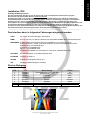
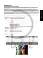
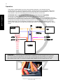
1
Multimedia Interface
Bedienungsanleitung
Instruction manual
1280
Audiotechnik Dietz® Vertriebs-GmbH ● Benzstr. 12 ● 67269 Grünstadt ● [email protected] ● www.dietz.biz
Copyright © by Audiotechnik Dietz® Vertriebs-GmbH ● Germany
Rev 6, Stand: 07 / 2008
D
E
U
T
S
C
H
2
Inhaltsverzeichnis
Inhaltsverzeichnis ....................................................................................................................................................2
Allgemeine Hinweise ...............................................................................................................................................2
Lieferumfang............................................................................................................................................................2
Allgemeine Sicherheitshinweise ..............................................................................................................................3
Hinweise auf Voraussetzungen für den Bestimmungsmäßigen Betrieb .................................................................4
Installation 1280.......................................................................................................................................................5
Das Interface kann in folgenden Fahrzeugen eingesetzt werden ...........................................................................5
Funktion ...................................................................................................................................................................6
Wartungshinweise ...................................................................................................................................................7
Technische Daten....................................................................................................................................................7
Einbauanleitung .....................................................................................................................................................14
Allgemeine Hinweise
Sehr verehrter Kunde,
vielen Dank, dass Sie sich für ein Produkt der Firma Audiotechnik Dietz entschieden haben. Sie haben eine
hervorragende Wahl getroffen.
Bei der Entwicklung des Produktes wurde besonders auf Ihre persönliche Sicherheit, kombiniert mit
bestmöglichstem Bedienungskomfort, modernem Design und aktuelle Produktionstechniken geachtet.
Aber trotz größtmöglicher Sorgfalt kann es bei unsachgemäßer Installation oder Benutzung, oder bei falscher
Bedienung zu Verletzungen oder/und Sachschäden kommen.
Bitte lesen Sie deshalb die Ihnen vorliegende Bedienungsanleitung sorgfältig und vollständig durch und
bewahren Sie diese auf!
Dieses Produkt erfüllt die Anforderungen der geltenden europäischen und nationalen Richtlinien. Die
Konformität wurde nachgewiesen, die entsprechenden Unterlagen und Erklärungen sind beim Hersteller
hinterlegt.
Alle Artikel aus unserer Produktion durchlaufen eine 100%ige Prüfung – zu Ihrer Sicherheit.
Wir behalten uns vor, jederzeit technische Änderungen durchzuführen, die dem Fortschritt dienen.
Je nach Artikel und Einsatzzweck ist es eventuell notwendig, vor der Installation bzw. Inbetriebnahme die
gesetzlichen Bestimmungen des jeweiligen Landes zu prüfen.
Das Gerät ist bei Garantieansprüchen in der Originalverpackung mit beigelegtem Kaufbeleg und detaillierter
Fehlerbeschreibung dem Verkäufer einzuschicken. Beachten sie hierbei die Rücksendebestimmungen des
Herstellers (RMA). Es gelten die gesetzlichen Gewährleistungsvorschriften.
Der Garantieanspruch und auch die Betriebserlaubnis erlischt durch:
a) unbefugte Änderungen am Gerät oder Zubehör, die nicht vom Hersteller oder dessen Partnern
durchgeführt oder genehmigt wurden
b) öffnen des Gehäuses eines Gerätes
c) selbst ausgeführte Reparaturen am Gerät
d) unsachgemäße Nutzung / nicht bestimmungsgemäße Nutzung / Betrieb
e) Gewalteinwirkung auf das Gerät (Herabfallen, mutwillige Zerstörung, Unfall, etc.)
Beachten Sie beim Einbau alle sicherheitsrelevanten und gesetzmäßigen Bestimmungen.
Das Gerät darf nur durch geschultes Fachpersonal oder ähnlich qualifizierte Personen eingebaut werden.
Lieferumfang
- 1 St. Bedienungsanleitung
- 1 St. Multimedia Interface
- 4 St. Abzweigverbinder, rot
- 4 St. Rundstecker rot
- 4 St. Rundsteckhülsen rot
Copyright © by Audiotechnik Dietz® Vertriebs-GmbH ● Germany
Rev 6, Stand: 07 / 2008
3
Allgemeine Sicherheitshinweise
WARNUNG
Die Installation darf nur durch geschultes Fachpersonal durchgeführt werden. Installationen nur im
spannungslosen Zustand vornehmen. Dafür z.B. die Batterie vom Bordnetz trennen, beachten Sie dabei bitte die
Vorgaben des Fahrzeugherstellers.
•
•
•
Verwenden Sie niemals sicherheitsrelevante Schrauben, Bolzen oder sonstige Befestigungspunkte an
Lenkung, Bremssystem oder anderen Komponenten, um Ihre eigene Fahrsicherheit nicht zu gefährden.
Schließen Sie das Gerät nur an 12V KFZ Spannung mit Masseverbindung zur Karosserie an.
Diese Unterbaugruppe ist nicht zugelassen zum Einsatz in LKWs oder anderen KFZ mit 24V Bordspannung.
Vermeiden Sie den Einbau des Gerätes an Stellen wodurch die Fahrsicherheit oder die Funktionstüchtigkeit
anderer im Fahrzeug verbauter Unterbaugruppen eingeschränkt würde.
HINWEIS
Bitte verwenden Sie die in dieser Montageanleitung vorgeschriebenen Anschlüsse zur Montage des Gerätes.
Die hier aufgeführten Hinweise treffen zwar auf die meisten, aber nicht auf alle Produkte gleichermaßen zu!
Sollten Sie Fragen hierzu haben, wenden Sie sich bitte an Ihren Händler.
Lassen Sie das Gerät nicht fallen! Vermeiden Sie Beschädigungen! Ist das Gerät
heruntergefallen, oder ist das Gehäuse beschädigt, wenden Sie sich bitte an einen
Servicepartner.
Achtung! Gefahr von Elektroschock! Öffnen Sie nie das Gehäuse! Es gibt keine zu
wartenden Teile im Inneren. Lassen Sie Service- oder Reparaturarbeiten nur von
qualifizierten Personen durchführen.
Achtung! Gefahr von Brand oder Elektroschock! Setzen Sie das Gerät keinem Regen
oder anderer Feuchtigkeit (Badewanne, Schwimm- oder Spülbecken) aus. Stellen Sie
keine wasserbeinhaltenden Objekte wie beispielsweise Trinkgläser oder Blumenvasen
auf dem Gerät ab.
Achtung! Gefahr von Elektroschock! Vermeiden Sie bei Gewitter eine Berührung mit dem
Gehäuse und ziehen Sie die Stecker der Spannungsversorgung und Antennen vom
Gerät ab, um Schäden zu vermeiden.
Achtung! Gefahr von Brand oder Elektroschock! Überlasten Sie auf keinen Fall die
Stromanschlüsse oder die Verlängerungskabel.
Achtung! Gefahr von Brand oder Elektroschock! Stecken Sie niemals Fremdkörper in die
Öffnungen am Gehäuse! Die Gegenstände können Kurzschlüsse verursachen.
Achtung! Gefahr von Brand oder Elektroschock! Sollte das Kabel oder der
Anschlußstecker des Gerätes beschädigt sein, ziehen Sie den Stecker heraus und
wenden Sie sich an einen Servicepartner.
Achtung! Gefahr von Brand oder Elektroschock! Sorgen Sie dafür, dass das Stromanschlußkabel nicht gequetscht wird.
Schalten Sie bei Rauch-, Geräusch- und/oder Geruchsentwicklung das Gerät sofort ab
und trennen Sie es sofort von der Spannungsversorgung. Benutzen Sie das Gerät nicht
weiter!
Setzen Sie das Gerät keiner starken Sonnenbestrahlung oder anderen starken
Hitzeeinwirkungen aus! Montieren Sie das Gerät nie in der Nähe von oder gar über
Radiatoren, Warmluftschläuchen oder anderen Wärmequellen.
Copyright © by Audiotechnik Dietz® Vertriebs-GmbH ● Germany
Rev 6, Stand: 07 / 2008
D
E
U
T
S
C
H
D
E
U
T
S
C
H
4
Sorgen Sie für genügend Luftzirkulation um Schäden an den Gerätekomponenten zu
vermeiden.
Ziehen Sie bitte den Stecker der Stromversorgung, wenn:
a) Sie das Gerät längere Zeit nicht benutzen
b) Sie das Gerät reinigen möchten (benutzen Sie keine feuchten- oder Sprüh-Reiniger.
Verwenden Sie nur trockene Tücher zur Reinigung).
c) das Gerät trotz Überprüfung mit Hilfe der Fehlersuche nicht funktioniert (wenden Sie
sich in diesem Falle an einen unserer Servicepartner)
Platzieren Sie das Gerät nie in staubiger Umgebung. Staubzusammenballung infolge
von Temperatureinwirkung kann das Gerät zerstören.
Verstopfen Sie keine Öffnungen am Gehäuse, an der Rückseite oder am Boden.
Stellen Sie das Gerät nie auf ein Bett, Sofa oder ähnliche Oberflächen. Auch hier können
die Öffnungen verdeckt werden.
Stellen Sie das Gerät nie in geschlossen umbaute Möbel, wenn dadurch die
Luftzirkulation gefährdet wird.
Stellen Sie das Gerät nicht auf instabile Unterkonstruktionen. Durch Herunterfallen des
Gerätes könnten Sie verletzt und das Gerät beschädigt werden.
Lassen Sie Reparaturen immer nur von unseren Servicepartnern durchführen! Bei selbst
reparierten Geräten erlischt der Garantieanspruch!
Wenn Sie eine durchgeschmolzene Sicherung ersetzen müssen, schalten Sie das Gerät
ab und trennen Sie es von der Spannungsversorgung. Benutzen Sie nur Sicherungen
gleicher Stärke als Ersatz, um Schäden am Gerät zu vermeiden!
Hinweise auf Voraussetzungen für den Bestimmungsmäßigen Betrieb
Setzen Sie das Gerät nur in dem ihm zugedachten Bereich ein.
Bei zweckfremdem Gebrauch, nicht fachgerechter Installation oder bei Umbauten erlöschen die Betriebserlaubnis und der Garantieanspruch.
Copyright © by Audiotechnik Dietz® Vertriebs-GmbH ● Germany
Rev 6, Stand: 07 / 2008
5
Installation 1280
Achtung! Unbedingt lesen!!!
Das hier beschriebene Interface ist nur für den Einsatz in den nachstehenden Kombinationen geeignet.
Bei falschem oder fehlerhaftem Einbau erlischt die Garantie.
Die Baugruppe 1280 ist ein Interface, das aus dem Innenraum CAN-Protokoll eines Fahrzeugs nachstehend
beschriebene Daten verarbeitet. Durch den Einbau dieses Artikels in ein Fahrzeug greift man in ein komplexes
Gesamtsystem ein, das wir als Hersteller und Lieferant der o.g. Baugruppe nur bedingt kennen können, da
Unstetigkeiten des Serienstandes innerhalb einer Modellreihe und eines Modelljahres eine Übertragbarkeit der hier
beschriebenen Kombinationen nicht in jedem Fall zulassen, weshalb eine Haftung ausgeschlossen ist. Bitte
beachten Sie daher generell beim Einbau von elektronischen Baugruppen in Fahrzeugen die Einbaurichtlinien und
Garantiebestimmungen des Fahrzeugherstellers, damit die Fahrzeuggarantie nicht erlischt.
_______________________________________________________________________________________________
Das Interface kann in folgenden Fahrzeugen eingesetzt werden
AUDI
A3, A4 mit 16:9 DVD Navigation Plus RNS-E
BMW
3er E90, 5er E60, 7er E65 und X5 E70 nicht kompatibel für BMW Rear Seat Entertainment
MERCEDES C-Klasse W203 und E-Klasse W210 mit COMAND 2.0 und original TV Tuner
A-W169, B-W245, C-W203, CLK-W209, M-W164, R-W251 mit COMAND APS NTG2
E-Klasse W211 mit COMAND APS
CLS W219 mit COMAND APS
SLK R171 mit COMAND APS
SL R230 mit COMAND 2.0 und original TV Tuner bzw. COMAND APS DVD
PEUGEOT
407 mit Navigations- und Telematiksystem RT3
PORSCHE
Cayenne mit PCM 2.1
SKODA
Octavia II mit Navigation Nexus 16:9
VW
mit MFD2 / RNS2 Navigation, Phaeton
Stecker Belegung
PIN
1
2
3
4
5
6
7
8
I/O
Eingang
Ausgang
Eingang
Eingang
Eingang
Eingang
Ausgang
Ausgang
Bezeichnung
Dauerspannung +12 V, KL. 30
Steuerleitung + 5V
CAN low
CAN high
Masse
Schalter
CAN low
CAN high
Copyright © by Audiotechnik Dietz® Vertriebs-GmbH ● Germany
Rev 6, Stand: 07 / 2008
Kabel
rot
orange
blau
gelb
schwarz
violett
blau
gelb
DD
EE
UU
TT
SS
CC
HH
D
E
U
T
S
C
H
6
Funktion
Das Interface 1280 wird an Dauerplus (Kl. 30) und Masse (Kl.31) angeschlossen. Aufgrund der Bauart muss
das Interface in die CAN Datenbusleitungen geschaltet werden. Dazu werden diese durchtrennt und mit den
Pins 3, 4 und 7, 8 am Interface verbunden. Zur Montage können die beiliegenden Rundhülsen
verwendet werden.
ACHTUNG: Niemals CAN high und low gleichzeitig durchschneiden!! Jede Leitung einzeln!!!
Das Interface vor der Montage vom Kabelsatz trennen, und erst nach Anschliessen aller Kabel wieder
anstecken.
Zum aktivieren der Funktion während der Fahrt (nur Rückwärts) muss die violette Leitung des 1280 mit dem
Rückfahrscheinwerfer verbunden werden. Liegt hier eine Schaltspannung von +12V an, so ist das Interface
aktiv und ermöglicht das, z.B. von einer Rückfahrkamera, gelieferte Bild auf dem Navigationsmonitor zu
sehen. Um das Umschalten zu automatisieren, liefert das Interface bei eingelegtem Rückwärtsgang über die
orange Leitung ein Schaltsignal von +5V (I max. 30mA). Dieses kann als Steuersignal verwendet werden
kann.
HINWEIS
Bei manchen Fahrzeugen (z.B. VW Touareg) sind die Anschlüsse für den CAN Bus an der Navigation
jeweils doppelt belegt. Hier müssen beide Kabel einer Doppelbelegung abgetrennt, und mit dem jeweiligen
Eingang für CAN high und CAN low am 1280 verbunden werden. Um Fehler beim Einbau zu vermeiden
empfehlen wir den Kabelsatz 1282 zu verwenden.
Copyright © by Audiotechnik Dietz® Vertriebs-GmbH ● Germany
Rev 6, Stand: 07 / 2008
7
Wartungshinweise
Das Gerät bedarf keiner Wartung.
Zum Reinigen des Gerätes benutzen Sie bitte nur ein trockenes Tuch zum Abwischen. Gegebenenfalls können
Sie bei stärkerer Verschmutzung das Gerät vorsichtig mit einem leicht angefeuchteten Tuch reinigen.
Benutzen Sie keinesfalls scharfe Reinigungsmittel zum Säubern des Gerätes.
Technische Daten
Software:
SW 3.2.1
Spannungsversorgung:
12 V DC
Spannungs-Arbeitsbereich: 10,0 – 14,6 V DC
Ruhestrom:
< 7 mA
Leistungsaufnahme max.: 0,58 W
Temperaturbereich:
-40 bis +85 °C
Gewicht:
0,107 kg
Abmessungen:
70 x 50 x 30 mm
Das Gerät ist für den automotiven Bereich gedacht und hat daher eine Lebensdauer von maximal 10 Jahren.
Audiotechnik Dietz® Vertriebs-GmbH
Benzstr. 12
D-67269 Grünstadt
Germany
[email protected]
www.dietz.biz
Copyright © by Audiotechnik Dietz® Vertriebs-GmbH ● Germany
Rev 6, Stand: 07 / 2008
D
E
U
T
S
C
H
8
Table of content
E
N
G
L
I
S
H
Table of content .......................................................................................................................................................8
General advice.........................................................................................................................................................8
Scope of delivery .....................................................................................................................................................8
General safety instructions ......................................................................................................................................9
References of legal regulations for operation........................................................................................................10
Installation 1280.....................................................................................................................................................11
The interface can be used in the following cars ....................................................................................................11
Connector assignment:..........................................................................................................................................11
Operation ...............................................................................................................................................................12
Service notes .........................................................................................................................................................13
Technical data .......................................................................................................................................................13
Installation..............................................................................................................................................................14
General advice
Dear client,
many thanks for having chosen an Audiotechnik Dietz product. You have made a magnificent choice.
While developing this product, your personal safety combined with the best operating service, modern design
and an up-to-date production technique was especially taken into account.
Unfortunately, despite the utmost care injuries and/or damages might occur due to improper installation and/or
use.
Please read the attached instruction manual completely with great care and keep it!
This product meets the actual European and national directions. The conformity was proved, the respective
documents and explanations are stored with the manufacturer.
All articles of our production line pass through a 100 % check - for your safety and security.
We reserve the right to carry out technical changes which serve the improvement at any time.
According to each article and purpose, it is sometimes necessary to check each country´s legal regulations
before installing and starting the unit.
In case of guarantee claims, the device has to be sent back to the seller in the original packaging with the
attached bill of purchase and detailed defect's description. Please pay attention to the manufacturer's return
requirements (RMA). The legal warranty directions are valid.
The guarantee claim as well as the operating permission becomes invalid due to:
a) unauthorized changes to the device or accessories which have not been approved or carried out by the
manufacturer or its partners
b) opening the device's frame
c) device's repairs carried out by one's own
d) improper use / operation
e) brute force to the device (drop, wilful damage, accident etc.)
During installation, please pay attention to all safety relevant and legal directions.
The device has only to be installed by trained personnel or similarly qualified people.
Scope of delivery
- 1 pc. instruction manual
- 1 pc. multimedia interface
- 4 pc. shunt connector, red
- 4 pc. male bullet connector
- 4 pc. female bullet connector
Copyright © by Audiotechnik Dietz® Vertriebs-GmbH ● Germany
Rev 6, Stand: 07 / 2008
9
General safety instructions
WARNINGS
Installation requires special knowledge.
Do not install the unit yourself. For safe and reliable installation, consult a dealer having special knowledge.
Installation may only be done during idle status. Disconnect the battery from the car´s electrical system, for
example. Thereby, please pay attention to the car´s manufacturer-requirements.
•
•
•
Never use bolts or nuts from the car´s safety devices for installation.
If bolts or nuts from the steering wheel, brakes or other safety devices are used for installation of the unit, it may cause
an accident.
Use the unit with a DC 12V negative ground car.
This unit cannot be used in large trucks which use a DC 24V battery. If it is used with a DC 24V battery, it may cause
a fire or accident.
Avoid installing the unit in following places:
- Where it would hinder your safe driving.
- Where it could damage the car´s fittings.
CAUTION
Since there may be legal regulations defining the permissible installation locations for this unit, be sure to install it
in a location complying with any such laws.
The references in this chapter apply to most of our products, but not to all. If you have further questions, please
contact your local dealer.
Do not hit this product. Avoid any damage.
Warning! Risk of electric shock! Never remove the cover. There are no user-serviceable
parts inside. Refer servicing to qualified personal.
Warning! Risk of fire or electric shock! Do not use this product near water (for example
bathtub, washbowl, etc.) or in wet basements (swimming pool). To reduce the risc of
casualties, never expose the unit any moisture. Never put a wet object (like a flower pot) on
the unit.
Warning! Risk of electric shock! To protect the unit against damage, unplug the power
cable and the antennas of the unit if a thunder is present.
Warning! Risk of fire or electric shock! Do not overload wall outlets and extension cords.
Warning! Risk of fire or electric shock! Never insert objects of any kind into this product
through openings. They can cause short circuits, which could result in fire or electric shock.
Warning! Risk of fire or electric shock! When the cable or plug of this product is broken,
please pull out the plug and refer servicing to qualified personal.
Warning! Risk of fire or electric shock! Don´t put anything on the power cable! This can
damage the cable.
If smoking, abnormal sound or peculiar smell happens, disconnect the power source. Stop
using this unit.
Copyright © by Audiotechnik Dietz® Vertriebs-GmbH ● Germany
Rev 6, Stand: 07 / 2008
E
N
G
L
I
S
H
10
Protect the unit against any kind of heat. Never mount it close to heat sources. This product
should never be placed near or over a radiator or under the sun.
This product should not be placed in a built-in installation such as a bookcase or rack
unless proper ventilation is provided.
E
N
G
L
I
S
H
Unplug the power cable if:
a. the unit is unused for a long time
b. you want to clean the unit. (Do not use liquid cleaners or aerosol cleaners. Use a dry
cloth for cleaning).
c. the unit doesn´t work, even after you have consulted the troubleshooting chapter (in this
case, please contact a service-partner).
Do not place this unit on extension dust. If the temperature is highly damp, agglomerate
dust will damage the unit.
Do not block Slots and openings in the cabinet or in the back or bottom.
The openings should never be blocked by placing the product on a bed, sofa, rug or other
similar surfaces.
This product should not be placed in a built-in installation such as a bookcase or rack
unless proper ventilation is provided.
Do not place this product on an unstable cart, stand, table, etc. The product may fall,
causing serious injury and serious damage to the product.
Repairs should only be made by our service-partners. Never do a repair self, otherwise the
claim of guarantee expires.
Unplug the unit from the power source if you have to replace a burned fuse. Only use fuses
of the same kind and size. Wrong fuses can damage the unit!
References of legal regulations for operation
Only use this unit in the intended domain.
If you use it in a foreign domain, if the unit is not installed properly, or if the unit will be reconstructed, the
guarantee will expire.
Copyright © by Audiotechnik Dietz® Vertriebs-GmbH ● Germany
Rev 6, Stand: 07 / 2008
11
Installation 1280
Attention!! Absolutely necessary to read!!!
The interface 1280 is only for use of the afterwards described combination. If the device is installed incorrect,
warranty will be lost.
Unit 1280 is an interface which processes afterwards described data from the CAN-protocol of a car.
Its’ installation in a car means an important interference into a complex system which we as a supplier of the
above mentioned unit do not know very well. We cannot guarantee that picking off data from the CAN Bus system
may not influence other electronic units or systems in the car. So if you install electronic units in cars, please
always pay attention to the installation-guides and the warranty-regulations of the car producer because otherwise
the warranty will be lost. Because the changes in mass-production of the cars, we also cannot guarantee, that the
interface is suitable in all the above mentioned combinations. To avoid risks, we advise you to contact the car
producer or one of his dealers.
_______________________________________________________________________________________________
The interface can be used in the following cars
AUDI
A3, A4 with 16:9 DVD Navigation Plus RNS-E
BMW
Series 3 E90, Series 5 E60, Series 7 E65 and X5 E70 not compatible for BMW Rear Seat
Entertainment
MERCEDES C-Class W203 and E-Class W210 with COMAND 2.0 and original TV tuner
A-W169, B-W245, C-W203, CLK-W209, M-W164, R-W251 with COMAND APS NTG2
E-Class W211 with COMAND APS
CLS W219 with COMAND APS
SLK R171 with COMAND APS
SL R230 with COMAND 2.0 and original TV tuner / COMAND APS DVD
PEUGEOT
407 with navigation system RT3
PORSCHE
Cayenne with PCM 2.1
SKODA
Octavia II with Nexus 16:9 navigation
VW
with MFD2 / RNS2 navigation, Phaeton
Connector assignment:
PIN
1
2
3
4
5
6
7
8
I/O
Input
output
Input
Input
Input
Input
output
output
marking
Power +12 V, KL. 30
remote + 5V
CAN low
CAN high
ground
switch
CAN low
CAN high
Copyright © by Audiotechnik Dietz® Vertriebs-GmbH ● Germany
Rev 6, Stand: 07 / 2008
cable
red
orange
blue
yellow
black
purple
blue
yellow
E
N
G
L
I
S
H
12
Operation
The interface 1280 basically has to be connected with permanent +12V (terminal 30) and
ground (terminal 31). Due to the electronic design, the interface has to be connected in serial to the
CAN bus wires. Therefore the CAN bus has to be cut through and connected with Pin 3, 4 and 7, 8
to the interface 1280. For assembling the enclosed bullet sleeves can be used.
E
N
G
L
I
S
H
ATTENTION: Never cut CAN high and low simultaneously!! Only one single wire!!
Connection of cables should only be done with a disconnected interface.
For activating the stand by function of the picture while driving (only backwards), the purple wire from
1280 has to be connected with the signal for back up light. A voltage of +12V at the purple wire activates
the interface and makes it possible to view the picture of a for rear view camera on the navigation
screen while moving. For an automation of switching, the interface delivers a signal of +5V (I max.
30mA) at the orange wire, as long as the reverse gear is laid in. This signal can be used as a remote
signal.
ATTENTION
In some cars (e.g. VW Touareg) the connections for CAN Bus are double clogged at the navigation
unit. In this case, both cables have to be cut and connected with the particular input for CAN high
and CAN low at the 1280. To avoid any mistakes while installing we recommend cable kit 1282.
Copyright © by Audiotechnik Dietz® Vertriebs-GmbH ● Germany
Rev 6, Stand: 07 / 2008
13
Service notes
This unit does not need any servicing.
Do not open the housing. There are no user-serviceable parts inside.
Wipe gently with a dry cloth over the surface to clean the unit. If there is more tough dirt, first use a light wet
cloth and then use a dry one. Never use corrosive cleaners to clean the unit.
Technical data
Software:
SW 3.2.1
Power supply:
12 V DC
Working Voltage:
10,0 – 14,6 V DC
Quiescent current:
< 7 mA
Power consumption: 0,58 W
Temperature range: -40 - +85 °C
Weight:
0,107 kg
Dimensions:
70 x 50 x 30 mm
This unit is only for automotive use and has therefore a lifetime of max. 10 years.
Audiotechnik Dietz® Vertriebs-GmbH
Benzstr. 12
D-67269 Grünstadt
Germany
[email protected]
www.dietz.biz
Copyright © by Audiotechnik Dietz® Vertriebs-GmbH ● Germany
Rev 6, Stand: 07 / 2008
E
N
G
L
I
S
H
14
Einbauanleitung:
Installation:
AUDI DVD Navigation RNS-E (A3, A4):
Die Installation findet hinter der Navigationseinheit statt. Dazu
muss diese Ausgebaut und vom Bordnetz getrennt werden.
Belegung des MOST Steckers an der Navigation:
orange / lila:
CAN high pin 9
orange / braun: CAN low pin 10
braun:
Masse pin 12
rot / gelb:
Dauerplus pin 15
Wird der Kabelsatz 1282 verwendet, wird dieser zwischen die MOST Buchse des Fahrzeugs und den MOST
Stecker der Navigationseinheit installiert. Ein abgreifen der oben beschriebenen Leitungen ist nicht nötig.
Die Belegung der losen violetten und orangenen Leitung finden Sie auf Seite 5.
ACHTUNG:
Solange das Interface 1280 aktiv ist, kann mit der Navigation RNS-E nicht gleichzeitig navigiert
werden!
Installation has to be done behind the navigation unit.
Therefore the unit has to be pulled out and disconnected
from the cars’ electrical system.
Assignment of the MOST connector at the navigation unit:
orange / purple:
orange / brown:
brown:
read / yellow:
CAN high pin 9
CAN low pin 10
ground pin 12
permanent +12V pin 15
If cable kit 1282 is used, it is installed between the vehicle MOST
plug and the navigation unit’s MOST connector. Cutting the wires is not necessary. The wiring of the
loose purple and orange cable is described on page 11.
ATTENTION:
With an activated interface 1280 it is not possible to navigate with RNS-E simultaneously.
BMW 3er E90, 5er E60, X5 E70 / Series 3 E 90, Series 5 - E60, X5 E70
Die Installation findet hinter der Navigationseinheit statt,
nicht (!) am Monitor. Dazu muss diese Ausgebaut und vom Bordnetz
getrennt werden. Belegung des MOST Steckers an der Navigation:
gelb:
CAN low pin 9
schwarz:
CAN high pin 11
braun:
Masse pin 12
braun / rot:
Dauerplus pin 15
Wird der Kabelsatz 1283 verwendet, wird dieser zwischen die MOST
Buchse des Fahrzeugs und den MOST Stecker der Navigationseinheit
installiert. ACHTUNG: Eventuell vorhandenen Lichtleiter vom Fahrzeug MOST Anschluss in die
Anschlussbuchse des Kabelsatzes stecken.
Ein abgreifen der oben beschriebenen Leitungen ist nicht nötig. Die Belegung der losen violetten und
orangenen Leitung finden Sie auf Seite 5.
ACHTUNG:
Solange das Interface 1280 aktiv ist, kann mit der Navigation ab Baujahr 06/07 nicht gleichzeitig
navigiert werden!
Copyright © by Audiotechnik Dietz® Vertriebs-GmbH ● Germany
Rev 6, Stand: 07 / 2008
15
Installation has to be done behind the navigation unit,
not (!) behind the monitor. Therefore the unit has to be pulled out
and disconnected from the cars’ electrical system.
Assignment of the MOST connector at the navigation unit:
yellow:
CAN low pin 9
black:
CAN high pin 11
brown:
ground pin 12
brown / red: permanent +12V pin 15
If cable kit 1283 is used, it is installed between the vehicle MOST plug and the navigation unit’s MOST
connector. ATTENTION: Possibly installed fibre optics have to be disconnected from the vehicle
MOST plug and reconnected in the cable kit MOST plug. Cutting the wires is not necessary. The wiring
of the loose purple and orange cable is described on page 11.
ATTENTION:
With an activated interface 1280 it is not possible to navigate simultaneously 06/07 on.
BMW 7er / Series 7 - E65
Die Installation findet hinter dem Monitor statt. Den Monitor wie unten Abgebildet ausbauen:
Installation has to be done behind the monitor. For removal of the monitor see following pictures:
Zündung ausschalten und den grossen AMP Stecker aus dem Monitor ziehen.
Belegung des AMP Steckers:
orange / grün:
grün:
braun / schwarz:
rot / schwarz:
CAN high
CAN low
Masse
Dauerplus
ACHTUNG:
Solange das Interface 1280 aktiv ist, kann mit der Navigation ab Baujahr 06/07 nicht gleichzeitig
navigiert werden!
Turn off the ignition and disconnect the big AMP connector from the monitor.
Assignment of the AMP connector:
orange / green: CAN high
green:
CAN low
brown / black: ground
red / black:
permanent +12V
ATTENTION:
With an activated interface 1280 it is not possible to navigate simultaneously 06/07 on.
Copyright © by Audiotechnik Dietz® Vertriebs-GmbH ● Germany
Rev 6, Stand: 07 / 2008
16
MERCEDES C-W203, E-W210, SL R230 mit / with COMAND 2.0:
Die Installation findet hinter der Navigationseinheit statt. Dazu
muss diese Ausgebaut und vom Bordnetz getrennt werden.
Der Anschluss erfolgt am C2 Block:
braun / rot: CAN high pin 9
braun:
CAN low pin 8
Wird der Kabelsatz 1286 verwendet, beachten Sie bitte den Einbauhinweis der dem Artikel beiliegt.
Installation has to be done behind the navigation unit. Therefore
the unit has to be pulled out and disconnected from the cars’
electrical system. Connection at C2 as follows:
brown / red: CAN high pin 9
brown:
CAN low pin 8
If cable kit 1286 is used, see the manual of this product.
MERCEDES A-W169, B-W245, C-W203, CLK-W209, M-W164, R-W251 & COMAND APS NTG2:
Die Installation findet hinter der Navigationseinheit statt. Dazu muss diese Ausgebaut und vom Bordnetz
getrennt werden. Belegung des MOST Steckers an der Navigation:
braun:
braun / rot:
braun:
rot / blau:
CAN low pin 9
CAN high pin 11
Masse pin 12
Dauerplus pin 15
Wird der Kabelsatz 1283 verwendet, wird dieser zwischen die MOST
Buchse des Fahrzeugs und den MOST Stecker der Navigationseinheit
installiert. ACHTUNG: Eventuell vorhandenen Lichtleiter vom Fahrzeug
MOST Anschluss in die Anschlussbuchse des Kabelsatzes stecken.
Ein abgreifen der oben beschriebenen Leitungen ist nicht nötig.
Die Belegung der losen violetten und orangenen Leitung finden Sie
auf Seite 5.
Installation has to be done behind the navigation unit. Therefore
the unit has to be pulled out and disconnected from the cars’
electrical system.
Assignment of the MOST connector at the navigation unit:
brown:
CAN low pin 9
brown / red: CAN high pin 11
brown:
ground pin 12
red / blue:
permanent +12V pin 15
If cable kit 1283 is used, it is installed between the vehicle MOST plug and the navigation unit’s MOST
connector. ATTENTION: Possibly installed fibre optics have to be disconnected from the vehicle
MOST plug and reconnected in the cable kit MOST plug.Cutting the wires is not necessary. The wiring of
the loose purple and orange cable is described on page 11.
Copyright © by Audiotechnik Dietz® Vertriebs-GmbH ● Germany
Rev 6, Stand: 07 / 2008
17
MERCEDES E-Klasse / E-Class W211, CLS-W219:
Die Installation wird am AGW (Audio Gateway) im Kofferraum
vorgenommen, dazu muss die abgebildete Bedieneinheit
nicht (!) ausgebaut werden. Das AGW befindet sich links hinter
dem Halter für Navi Rechner und TV Tuner zwischen zwei
Karosseriewänden.
Abgriff für CAN high und low geschieht am Lichtwellenleiter
Anschluss Stecker vom AGW:
braun / rot: CAN high pin 2
braun:
CAN low pin 4
Installation has to be done at the AGW (Audio Gateway) in the
trunk, the control unit showed above has not (!) to be removed
for assembly. The AGW is located in the left side of the trunk
behind the retainer for navigation unit and TV tuner. It is
mounted between two body barriers. Tap off for CAN high and
low has to be done at the fibre optic
cable connector from the AGW:
brown / red: CAN high pin 2
brown:
CAN low pin 4
Fundort / Location AGW
MERCEDES SLK R171:
Die Installation wird am AGW (Audio Gateway) im vorderen
Beifahrerfußraum vorgenommen, dazu muss die abgebildete
Bedieneinheit nicht (!) ausgebaut werden.
Abgriff für CAN high und low geschieht am Lichtwellenleiter
Anschluss Stecker vom AGW:
braun / rot: CAN high pin 2
braun:
CAN low pin 4
Installation has to be done at the AGW (Audio Gateway)
in the front co-driver footwell, the control unit showed above
has not (!) to be removed for assembly.
Tap off for CAN high and low has to be done at the fibre optic
cable connector from the AGW:
brown / red: CAN high pin 2
brown:
CAN low pin 4
Fundort / Location AGW
Copyright © by Audiotechnik Dietz® Vertriebs-GmbH ● Germany
Rev 6, Stand: 07 / 2008
18
MERCEDES SL R230 mit Comand APS:
Die Installation wird am AGW (Audio Gateway) hinter dem
Fahrersitz vorgenommen, dazu muss die abgebildete
Bedieneinheit nicht (!) ausgebaut werden.
Abgriff für CAN high und low geschieht am Lichtwellenleiter
Anschluss Stecker vom AGW:
braun / rot: CAN high pin 2
braun:
CAN low pin 4
Installation has to be done at the AGW (Audio Gateway)
behind the driver seat, the control unit showed above
has not (!) to be removed for assembly.
Tap off for CAN high and low has to be done at the fibre
optic
cable connector from the AGW:
brown / red: CAN high pin 2
brown:
CAN low pin 4
______________________________________________________________________________________
PEUGEOT407:
Die Installation findet hinter der Navigationseinheit statt. Dazu
muss diese Ausgebaut und vom Bordnetz getrennt werden.
Belegung des MOST Steckers an der Navigation:
weiß:
grau:
CAN high pin 10
CAN low pin 13
Wird der Kabelsatz 1284 verwendet, wird dieser zwischen die MOST
Buchse des Fahrzeugs und den MOST Stecker der Navigationseinheit
installiert. ACHTUNG: Eventuell vorhandenen Lichtleiter vom Fahrzeug MOST Anschluss in die
Anschlussbuchse des Kabelsatzes stecken. Ein abgreifen der oben beschriebenen Leitungen ist nicht
nötig. Die Belegung der losen violetten und orangenen Leitung finden Sie auf Seite 5.
ACHTUNG:
Solange das Interface 1280 aktiv ist, kann mit der Navigation RT3 nicht gleichzeitig navigiert
werden! Zur Aktivierung des 1280 muss das Fahrzeug stehen!
Installation has to be done behind the navigation unit.
Therefore the unit has to be pulled out and disconnected
from the cars’ electrical system.
Assignment of the MOST connector at the navigation unit:
white : CAN high pin 10
grey: CAN low pin 13
If cable kit 1284 is used, it is installed between the vehicle MOST plug and the navigation unit’s MOST
connector. ATTENTION: Possibly installed fibre optics have to be disconnected from the vehicle
MOST plug and reconnected in the cable kit MOST plug.Cutting the wires is not necessary. The wiring
of the loose purple and orange cable is described on page 11.
ATTENTION:
With an activated interface 1280 it is not possible to navigate with RT3 simultaneously. For
activating 1280 the vehicle mustn’t move.
Copyright © by Audiotechnik Dietz® Vertriebs-GmbH ● Germany
Rev 6, Stand: 07 / 2008
19
PORSCHE Cayenne (PCM 2.1):
Die Installation findet hinter der Navigationseinheit statt. Dazu
muss diese Ausgebaut und vom Bordnetz getrennt werden.
Der Anschluss erfolgt am mini ISO Block:
orange / lila:
CAN high
orange / braun: CAN low
Wird der Kabelsatz 1285 verwendet, wird dieser zwischen die MINI ISO und ISO Buchse des Fahrzeugs
und den MINI ISO und ISO Stecker der Navigationseinheit installiert. Ein abgreifen der oben beschriebenen
Leitungen ist nicht nötig. Die Belegung der losen violetten und orangenen Leitung finden Sie auf Seite 3.
Installation has to be done behind the navigation unit. Therefore
the unit has to be pulled out and disconnected from the cars’
electrical system. Connection at mini ISO as follows:
orange / purple: CAN high
orange / brown: CAN low
If cable kit 1285 is used, it is installed between the MINI ISO and ISO
plug of the vehicle and the MINI ISO and ISO
connector of the navigation unit. Tapping off the wires is not necessary. The wiring of the loose purple and
orange cable is described on page 3.
______________________________________________________________________________________
VW MFD2 / RNS2, SKODA Nexus
Die Installation findet hinter der Navigationseinheit statt. Dazu
muss diese Ausgebaut und vom Bordnetz getrennt werden.
Belegung des MOST Steckers an der Navigation:
orange / lila:
orange / braun:
braun:
rot / gelb:
CAN high pin 9
CAN low pin 10
Masse pin 12
Dauerplus pin 15
Wird der Kabelsatz 1282 verwendet, wird dieser zwischen die MOST Buchse des Fahrzeugs und den
MOST Stecker der Navigationseinheit installiert. Ein abgreifen der oben beschriebenen Leitungen ist
nicht nötig. Die Belegung der losen violetten und orangenen Leitung finden Sie auf Seite 5.
ACHTUNG:
Bei VW Touareg bitte den Hinweis auf Seite 6 beachten!
Installation has to be done behind the navigation unit.
Therefore the unit has to be pulled out and disconnected
from the cars’ electrical system.
Assignment of the MOST connector at the navigation unit:
orange / purple:
orange / brown:
brown:
red / yellow:
CAN high pin 9
CAN low pin 10
ground pin 12
permanent +12V pin 15
If cable kit 1282 is used, it is installed between the vehicle MOST plug and the navigation unit’s MOST
connector. Cutting the wires is not necessary. The wiring of the loose purple and orange cable is
described on page 11.
ATTENTION:
With VW Touareg, please pay attention to the remarks on page 12!
Copyright © by Audiotechnik Dietz® Vertriebs-GmbH ● Germany
Rev 6, Stand: 07 / 2008
20
VW Phaeton
Die Installation findet hinter der Navigationseinheit (Monitor)
am grünem 32 pin Stecker statt, dazu muss diese Ausgebaut,
und vom Bordnetz getrennt werden.
Kabelfarben Fahrzeugseitig:
orange / grün: CAN high pin 16
orange / braun: CAN low pin32
braun:
Masse (Strom ISO pin 8)
rot:
Dauerplus (Strom ISO pin 7)
Installation has to be done behind the navigation unit.
Therefore the unit has to be pulled out and disconnected
from the cars’ electrical system. Assignment of the green
32 pin connector:
orange / green: CAN high (pin 16),
orange / brown: CAN low (pin 32),
braun:
ground (power ISO pin 8)
rot:
permanent +12V (power ISO pin 7)
Copyright © by Audiotechnik Dietz® Vertriebs-GmbH ● Germany
Rev 6, Stand: 07 / 2008