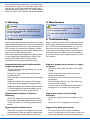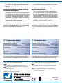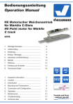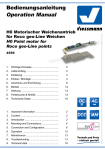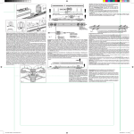
1
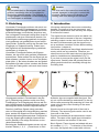
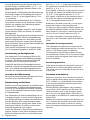
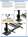
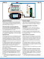
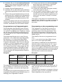
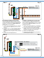
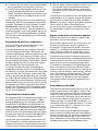
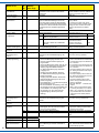
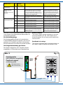
Bedienungsanleitung
Operation Manual
9500, 9501
0 Form-Hauptsignale
zweibegriffig
0 Semaphore Block Signals
two-aspect signals
1. Wichtige Hinweise......................................
2
2. Einleitung...................................................
3
3. Einbau / Montage........................................
5
4. Betrieb........................................................
12
5.Wartung
......................................................
14
6. Fehlersuche................................................
14
7. Technische Daten......................................
15
1. Important information .................................2
2. Introduction................................................3
3. Mounting and connection............................5
4. Operation.....................................................12
5. Maintenance...............................................14
6. Troubleshooting..........................................14
7. Technical data............................................15
DCC MM
Rail
Com
DE
1. Wichtige Hinweise
EN
1. Important information
Bitte lesen Sie vor der ersten Anwendung des
Produktes bzw. dessen Einbau diese Bedienungsanleitung aufmerksam durch und bewahren Sie
sie auf. Sie ist Teil des Produktes.
Please read this manual completely and attentively before using the product for the first time. Keep
this manual. It is part of the product.
Sicherheitshinweise
Safety information
Vorsicht:
Verletzungsgefahr!
Risk of injury!
Aufgrund der detaillierten Abbildung des Originals bzw. der vorgesehenen Verwendung kann
das Produkt Spitzen, Kanten und abbruchgefährdete Teile aufweisen. Für die Montage sind
Werkzeuge nötig.
Due to the detailed reproduction of the original
and the intended use, this product can have
peaks, edges and breakable parts. For installation tools are required.
Stromschlaggefahr!
Never put the connecting wires into a power
socket! Regularly examine the transformer for
damage. In case of any damage, do not use
the transformer!
Die Anschlussdrähte niemals in eine Steckdose einführen! Verwendetes Versorgungsgerät
(Transformator, Netzteil) regelmäßig auf Schäden überprüfen. Bei Schäden am Versorgungsgerät dieses keinesfalls benutzen!
Electrical hazard!
Packungsinhalt überprüfen
Checking the package contents
Kontrollieren Sie nach dem Auspacken den Lieferumfang auf Vollständigkeit:
Check the contents of the package for completeness after unpacking:
- Signalmodell mit Antriebseinheit und einem im
Kabel befindlichen Decoder,
- model of the signal with drive unit and the
decoder on the wires.,
- 2 Schrauben,
- 2 screws,
- ein Befestigungsclip,
- one mounting clip,
- eine Tafel mit selbstklebenden Bezeichnungsschildern,
- a board with self-adhesive labels,
- diese Anleitung.
Das Produkt richtig verwenden
Dieses Signal ist bestimmt:
- Zum Einbau in Modelleisenbahnanlagen und
Dioramen.
- Zum Anschluss an einem Modellbahntransformator (z. B. Art.-Nr. 5200) bzw. an einer
Modellbahnsteuerung mit zugelassener
Betriebsspannung.
- Zum Betrieb in trockenen Räumen.
Jeder darüber hinausgehende Gebrauch gilt als
nicht bestimmungsgemäß. Für daraus resultierende Schäden haftet der Hersteller nicht.
2
Caution:
- this manual.
Using the product for its correct
purpose
This product is intended:
- For installation in model railroad layouts and
dioramas.
- For connection to an authorized model
railroad transformer (e. g. item-No. 5200).
- For operation in dry rooms only.
Using the product for any other purpose is not approved and is considered incorrect. The manufacturer is not responsible for any damage resulting
from the improper use of this product.
Caution:
Achtung:
Die Antriebseinheit im Steuerkasten darf nicht
geöffnet, beschädigt oder mit Feuchtigkeit in
Verbindung gebracht werden. Der Decoder im
Zuleitungskabel ist ebenfalls vor Beschädigung
und Feuchtigkeit zu schützen.
The drive unit in the control box must not be
opened, damaged, or brought in contact with
moisture. Please protect the decoder in the
feeding cable from damage and moisture.
2. Einleitung
2. Introduction
Viessmann-Formsignale zeichnen sich durch vorbildgetreu langsame Flügelbewegung, ihr hervorragendes Preis-Leistungs-Verhältnis sowie durch
einfache Montage und einfachen Anschluss aus.
Das vorliegende Formsignal verfügt über einen Digitaldecoder und einen motorischen Antrieb. Geschwindigkeit und Bewegungsablauf sind elektronisch gesteuert und gewährleisten einen feinfühligen Antrieb. Zusätzlich verfügt der Decoder über
Ausgänge zur Zugbeeinflussung. Zudem kann
das Signal bei der Abwärtsbewegung realistisch
nachwippen (s. Kapitel 4).
Viessmann semaphores have some outstanding
benefits: Prototypical slow arm-movement, very
good price-performance-ratio and they are simple
to mount and connect.
Viessmann-Formsignale haben sehr filigrane
Masten, die sich durch eine perfekte Vorbildtreue
auszeichnen. Daher sollten Sie das Signal nie am
Mast anfassen, sondern immer nur an der Bodenplatte (Abb. 1). Bei einem Ausbau aus der Modellbahnplatte nicht oben ziehen, sondern die Elektronik unter der Platte greifen und nach oben hinausschieben!
Abb. 1
Fig. 1
This signal has an electronic drive unit which controls speed and movement of the arm. Integrated
switching-outputs can be used for train control. At
the end of the downward cycle the signal bounces up and down a number of times before settling
into position. (chapter 4)
Viessmann semaphores have finely detailed metal
masts, which are very sensitive. Therefore you
should never touch the masts but only the ground
plate for installation and deinstallation (Fig. 1).
If you have to unmount the signal, don’t pull the
signal mast. Carefully take the ground plate and
gently push the electronic assembly through the
mountiing hole.
Abb. 2
Fig. 2
Hauptsignale stehen in Deutschland in der Regel in Fahrtrichtung gesehen rechts vom Gleis.
Zweiflügelige Form-Hauptsignale können als Einoder Ausfahrsignale im Bahnhofsbereich oder als
Blocksignale auf der Strecke eingesetzt werden.
Adhesive signs are supplied with the signal. Simply cut out the desired sign and attach it to the signal box after removing the protecting foil. Here are
some rules for the correct marking of the semaphore signals:
Damit ein Lokführer Signale richtig zuordnen
oder im Störungsfall die richtige Meldung machen
kann, werden die Signale mit einer Buchstaben- /
Zahlenkombination gekennzeichnet. Die Bezeichnung des Signals gibt zusätzlich Auskunft über
seinen Standort. Hier einige Richtlinien zur korrekten Beschriftung:
Signals are set on the right side of the track in
Germany. Two-aspect-signals can be used in stations and on the route.
Blocksignale: Selbstblocksignale werden mit arabischen Zahlen (1, 2, 3, …) bezeichnet. In Rich-
Signals are marked with an alphanumeric combination. The name of the signal gives information
about its position and direction of the route.
Block Signals: These signals are labeled with arabic numbers (1, 2, 3, ...). In direction of the kilometre count, the signals are counted with odd num-
3
tung der Kilometrierung der Strecke wird mit ungeraden Zahlen vorwärts gezählt (1, 3, 5, …), in
der anderen Richtung mit geraden Zahlen rückwärts (z. B. 6, 4, 2, …).
Einfahrsignale: In Zählrichtung der Kilometrierung
der Strecke werden für Einfahrsignale die Buchstaben „A“ bis „E“, in der Gegenrichtung „F“ bis
„K“ verwendet.
Ausfahrsignale: Ausfahrsignale, die in Zählrichtung stehen, werden mit „N“ bezeichnet. Ausfahrsignale, die entgegen der Zählrichtung stehen,
werden mit „P“ bezeichnet.
Hinter dem Buchstaben eines Ein- oder Ausfahrsignals steht die Ziffer des Gleises, für welches
das Signal gilt.
Damit Sie Ihre Signale korrekt beschriften können,
liegt dem Signal eine Tafel mit selbstklebenden
Bezeichnungsschildern bei. Schneiden Sie das
gewünschte Schild aus, ziehen Sie die Schutzfolie ab und kleben Sie es auf die Nummerntafel am
Mast des Signals (Abb. 2).
Viele weitere Informationen über Signale finden
Sie im Viessmann-Signalbuch, Artikel-Nr. 5299.
Ansteuerung im Analogbetrieb
Das Viessmann Form-Hauptsignal können Sie
auch in analog gesteuerten Modellbahnanlagen
einsetzen. Sie können es sowohl mit Wechselstrom als auch mit Gleichstrom betreiben.
Entry Signals: In direction of the kilometre count of
the route, the signals are labeled with the letters
“A” to “E”, in the opposite direction “F” to “K”.
Exit Signals: In direction of the kilometre count of
the route, the signals are labeled with the letter
“N”, in the opposite direction with “P”.
Additional to the letter of an entry- or exit-signal
stands the number of the belonging track.
To label your railway signals correctly please use
the attached adhesive labels: cut the number you
have chosen for your layout, remove the protective foil, and put it on the signal post (Fig. 2).
For further information concerning railway signals refer to the Viessmann signal book (item-No.
5299).
Operation in analogue mode
The Viessmann semaphore block signal can be
used in analouge model railroad layouts. You may
use AC or DC power supply for operation.
The integrated controller and decoder recognizes automatically if there is AC or DC power supply
or a digital signal and adjusts itself to the correct
mode of operation.
Overload protection
Sobald Sie das Signal an Betriebsspannung anschließen, erkennt der integrierte Decoder automatisch, ob er analog oder digital angesteuert wird,
und stellt den entsprechenden Betriebsmodus ein.
If the signal recognizes a mechanical overload, it
switches off to protect itself against destruction.
The whole process of switching off may last up to
a short time.
Verhalten bei Überlastung
Feedback with RailCom
Bei mechanischer Überlastung schaltet der Decoder nach kurzer Zeit den Antrieb ab.
RailCom is a protocol for bi-directional communication in digital model railway layouts controlled in
DCC. It allows e. g. the feedback of the address
or the requested position from the signal to the
digital command station.
Rückmeldung mit RailCom
RailCom ist ein Zusatzprotokoll zur bidirektionalen
Kommunikation in digitalen Modellbahnanlagen,
die im DCC-Format gesteuert werden. Es ermöglicht z. B. die Stellungsrückmeldung des Signals
zur Digitalzentrale.
Das Versenden von RailCom-Nachrichten ist nur
in Anlagen möglich, in denen ein DCC-Signal an
den Schienen anliegt und seitens der Zentrale sowie des Boosters eine entsprechende Austastlücke im Datenstrom erzeugt wird. Daher ist die
Nutzung der RailCom-Funktion in einer reinen
Motorola-Umgebung nicht möglich.
4
bers (e. g. 1, 3, 5, ...). In the opposite direction
the signals are counted with even numbers backwards ( e. g. 6, 4, 2, ...)
Sofern der Decoder im Signal die Austastlücke registriert, sendet er nach einem erhaltenen Schaltbefehl als Quittung die Soll- und Ist-Stellung des
Signals zurück.
Sending RailCom messages is only possible in
layouts with a DCC signal on the rails and if the
command station and / or the booster(s) generate a cut-out in the digital signal. That’s why it is
not possible to use RailCom in a Motorola system
without DCC.
Whenever the decoder registers the RailCom cutout, it answers the switching commands with the
current state of the signal. In case of a moving
motor, the estimated remaining movement time is
reported.
3. Einbau / Montage
3. Mounting and connection
1. Beschriften Sie das Signal (siehe Kapitel 2).
2. Bohren Sie an der Montagestelle ein Loch mit
einem Durchmesser von 13 mm (Abb. 3,
passender Bohrer: Art.-Nr. 7801).
3. Führen Sie die Anschlusskabel einschließlich
der Elektronik von oben durch das Montageloch.
4. Befestigen Sie das Signal mit den beiliegenden
Befestigungsschrauben (siehe Abb. 4) bzw. mit
dem Befestigungsclip (siehe Abb. 5).
1. Label your railway signal as described in chapter 3.
2. Drill a mounting hole at the position of your signal (diameter 13 mm; see Fig. 3). A convenient drill is available from Viessmann (item-No.
7801).
3. Thread the cable and the decoder in the cable
from top to bottom through the mounting hole.
4. Fasten the signal post either with the attached
srews (see Fig. 4) or with the mounting clip
(see Fig. 5).
Abb. 4
Abb. 3
Fig. 4
Fig. 3
13 mm
Abb. 5
Fig. 5
Katalógusszám:
Terméknév:
Munkaszám:
Szerszámszám:
Tervező:
Fekete János
Dátum:
2012.02.22.
Rajzoló:
Fekete János
Dátum:
Ellenőr:
2012.02.22.
Méreta.:
1.5:1
Név:
Anya
9500 0-
Haupt
Dátum:
5
rot / red
Abb. 6
Fig. 6
grün / green
Universal Tasten - Stellpult
5547
braun
brown
16 V
Lichttransformator
Primär
230 V~
5200
Sekundär 10 V
0-10-16 V~
Primär
230 V 50 - 60 Hz
Sekundär 52 VA max. 3,25 A
IP 40 ta 25°C
0V
gelb / yellow
grün / green
5547
9500/
9501
Nur für trockene Räume
rot / red
Gefertigt nach
VDE 0570
EN 61558
5200
6
Werkseinstellungen
Default settings
Ab Werk ist der Decoder auf die Digitaladresse 1
(DCC-Protokoll) eingestellt. Weitere Konfigurationsmöglichkeiten entnehmen Sie bitte der CV-Tabelle auf den Seiten 10 und 11.
The factory setting for the digital address is 1
(DCC protocol). Please find further configuration
options in the CV table on the pages 10 and 11.
Konventioneller (analoger) Betrieb
Conventional mode of operation
(analogue)
Im konventionellen (analogen) Betrieb schalten
Sie das Signal mit geeigneten Tastenstellpulten
(z. B. Tastenstellpult Art.-Nr. 5547).
In case that you use the Viessmann signal on
conventional layouts, use a push button panel
(e. g. Push Button Panel item-No. 5547).
Schließen Sie das Signal und das Tastenstellpult
wie in Abbildung 6 gezeigt an. Verwenden Sie einen geeigneten Transformator (z. B. Art.-Nr. 5200).
Connect the signal and the push button panel
as shown in figure 6. Use a suitable transformer
(e. g. item-No. 5200).
Digitalbetrieb
Digital mode of operation
Dieser Decoder lässt sich als Schaltartikel ansteuern. Er bietet aber auch den Komfort, auf einer
Lokadresse angesteuert werden zu können. Dies
kommt den Modellbahnern entgegen, deren Zentrale keinen bequemen Zugriff auf Schaltartikel ermöglicht.
This decoder can be controlled as an accessory
decoder. However, it also offers the option to be
controlled with a locomotive address. This is particularly useful for modellers who do not have a
command station with easy access to accessories.
Im digitalen Betrieb schalten Sie das Signal über
eine Digitalzentrale. Legen Sie als erstes eine Digitaldresse fest. Lesen Sie dazu die beiden folgenden Kapitel und beachten Sie Abb. 8.
In the digital mode of operation, you use a digital command station to control the signal. Please
read the following two chapters to learn how to set
a digital address.
Nach Festlegung der Digitaladresse schließen Sie
das Signal an (Abb. 7).
Connect the signal to your digital layout as shown
in fig. 7.
Einrichtung mit DCC-Zentralen
Configure with DCC command stations
Zur digitalen Steuerung des Signals müssen Sie
diesem zunächst eine Digitaladresse zuweisen.
Zur Steuerung im DCC-System gehen Sie wie
folgt vor:
To use the signal in a digital environment, at first
you have to assign a digital address. To control the
signal with a DCC-system, observe the following
instructions:
1. Schalten Sie das Digitalsystem aus, z. B. NotAus. Es darf keine Spannung mehr am Gleis
anliegen.
1. Switch off the digital system (e. g. emergency
off). There must not be any power at the rails.
2. Verbinden Sie nur die rot markierte Steuerleitung und die Stromversorgungsleitungen des
Signalantriebs (braun und gelb, s. Abb. 7) mit
dem Gleis.
3. Schalten Sie das Digitalsystem ein.
4. Verbinden Sie nun die zweite (grün markierte)
Steuerleitung gleichfalls mit dem Gleis (s. Abb.
8).
5. Senden Sie mit der Digitalzentrale nun für die
gewünschte DCC-Adresse einen Schaltbefehl.
Der Signalantrieb empfängt den Befehl, registriert die Adresse und quittiert dies durch Umschalten.
Damit ist das Signal unter der neuen Adresse betriebsbereit. Falls Sie die Adresse künftig ändern
möchten, wiederholen Sie die Prozedur einfach.
2. Connect only the blue wire with the red marker and the power supply wires of the signal
(brown and yellow, fig. 7) to the rails.
3. Switch on the digital system.
4. Connect the second blue wire (green marker)
to the track signal too (fig. 8).
5. Use the digital command station to send a turnout-request for the desired DCC-address. The
decoder receives the request, registers the address as its own and as a receipt, it switches
the signal.
The signal is now ready to be used with the new
digital address. Whenever you want to change the
address, you just have to repeat the described
procedure.
Programmieren am Programmiergleis
Programming on the programming track
Die Konfiguration des Signals können Sie auch
direkt an dem Programmierausgang von Zentralen, die DCC-kompatibel sind, vornehmen. Verbinden Sie dazu die Anschlüsse des Signals wie in
Abb. 8 gezeigt mit dem Programmierausgang Ihrer Zentrale.
The configuration of the signal can also be accomplished by connecting it directly to the programming output of the command station. Simply connect the terminals of the decoder to the
programming output of the command station as
shown in fig. 8.
Die Adresse des Signals wird in zwei CVs programmiert. In CV 1 steht das untere Byte (LSB)
der Adresse, in CV 9 das obere Byte (MSB).
The address of the drive is programmed in two
CVs.
Das Umrechnen der Adresse geschieht wie im
Folgenden beschrieben. Wenn Sie eine Adresse
zwischen 1 und 255 eingeben wollen, so schreiben Sie diesen Wert direkt in CV 1. Den Wert in
CV 9 setzen Sie auf Null. Höhere Werte als 255
müssen aufgeteilt werden in das MSB und das
LSB. Teilen Sie die gewünschte Adresse durch
256 und ermitteln Sie das ganzzahlige Ergebnis
und den Rest.
Beispiele:
In CV 1 you set the lower byte (LSB) of the address, in CV 9 the upper byte (MSB).
The address is established as described below.
Write the address value directly into CV 1 if you
wish to assign an address between 1 and 255.
Set CV 9 to 0. Higher addresses than 255 must be
split into the MSB and the LSB: Divide the desired
address by 256 and determine the result without
decimal points as well as the remainder.
Examples:
Adresse
ganzzahliges
Ergebnis
Rest
CV 9
CV 1
256
1
0
1
0
911
3
911-256*3=143
3
143
1025
4
1025-256*4=1
4
1
Die weiteren Einstellmöglichkeiten entnehmen Sie
der CV-Tabelle. In CV 40 können Sie auch das
Protokoll festlegen, auf welches das Signal später „hört“.
Auf Befehle am Programmierausgang einer DCCkompatiblen Zentrale hört der Decoder immer unabhängig vom eingestellten Protokoll.
Further programming options are listed in the CV
table. You may also set the desired digital protocol in CV 40.
The decoder will respond to commands of the programming output of a DCC compatible command
station regardless of the set protocol.
7
Abb. 7
Fig. 7
9500/
9501
MM / DCC
Digitalzentrale
Digital Command Station
braun
brown
braun
brown
rot / red
grün / green
gelb / yellow
Einrichtung mit Motorola-Zentralen
Configure with Motorola central units
Damit Sie das Signal digital ansteuern können,
müssen Sie diesem zunächst eine Digitaladresse
zuweisen. Zur Steuerung im Märklin-MotorolaSystem gehen Sie wie folgt vor:
To use the signal in a digital environment, you
have to assign a digital address at first. To control
the signal with a Motorola-system, observe the
following instructions:
1. Schalten Sie das Digitalsystem aus, z. B. NotAus. Es darf keine Spannung mehr am Gleis
anliegen.
2. Verbinden Sie nur die grün markierte Steuerleitung und die Stromversorgungsleitungen
des Signals (braun und gelb, s. Abb. 7) mit dem
Gleis.
3. Schalten Sie das Digitalsystem ein.
1. Switch off the digital system (e. g. emergency
off). There must not be any power at the rails.
2. Connect only the blue wire with the green
marker and the power supply wires of the signal (brown and yellow, fig. 7) to the rails.
3. Switch on the digital system.
4. Connect the second blue wire (red marker) to
the track signal too (fig. 8).
Abb. 8
Fig. 8
9500/
9501
Adresse einstellen / Set address
rotes Kabel verbinden / connect red cable
DCC
MM
grünes Kabel verbinden / connect green cable
gelb / yellow
grün
green
88
rot
red
braun / brown
MM / DCC
Digitalzentrale
Digital Command Station
4. Verbinden Sie die zweite (rot markierte) Steuerleitung gleichfalls mit dem Gleis (s. Abb. 8).
5. Senden Sie mit der Digitalzentrale nun für die
gewünschte Motorola-Adresse einen Schaltbefehl. Das Signal empfängt den Befehl, registriert die Adresse und quittiert dies durch Umschalten.
Damit ist das Signal unter der neuen Adresse betriebsbereit. Falls Sie die Adresse künftig ändern
möchten, wiederholen Sie die Prozedur einfach.
Beachten Sie: Wenn Sie eine Zentrale einsetzen, die sowohl das DCC- als auch das Motorola-Format sendet, ist die Programmierung des Signals im DCC-Format empfehlenswert. Im Motorola-Format ist der Adressbereich auf 320 Adressen beschränkt.
Digitalbetrieb auf einer Lokadresse
Um den Decoder auf eine Lokadresse zu programmieren, gehen Sie wie folgt vor.
Zunächst stellen Sie sicher, dass alle Lokomotiven auf Fahrstufe Null stehen. Bestimmen Sie,
welches Digitalsystem verwendet werden soll. Gehen Sie dazu vor, wie unter den Punkten 1 bis 4
bei „Einrichtung mit DCC-Zentralen“ oder „Einrichtung mit Motorola Zentralen“ beschrieben. Stellen
Sie alle Lokomotiven auf Fahrstufe Null, sofern
Ihre Zentrale dies nicht automatisch tut.
An Punkt 5 senden Sie jedoch keinen Signalschaltbefehl, sondern einen Lok-Fahrbefehl auf
der Adresse, die der Antrieb bekommen soll. Betätigen Sie dazu den Fahrregler, sodass eine Fahrstufe an die Adresse gesendet wird, die nicht Null
ist. Diese Adresse entspricht der Gruppenadresse
eines typischen 4-fach-Decoders. Auf dieser Lokadresse wählen Sie dann eine Funktion F1 bis F4,
die dadurch dem Signal zugeordnet wird. Somit
können Sie 4 Signale auf eine Lokadresse legen,
analog zum 4-fach-Decoder. Der Adressbereich
ist auf 1 bis 99 begrenzt.
Programmieren mittels POM
Der Decoder lässt die Programmierung aller CVs
per POM („Programming on the Main“, „Hauptgleisprogrammierung“) zu. Nicht alle Zentralen
unterstützen POM Befehle an Schaltartikel-Decodern, deswegen kann man den Decoder auch
auf Lokdecoder-POM Modus umstellen. Dies geschieht dadurch, dass auf der Adresse 9999 der
Wert 80 in die CV 8 geschrieben wird. Der Signaldecoder hört dann auf normale POM-Befehle für
Lokomotiven unter seiner aktuellen Adresse.
Hier ist also Vorsicht geboten, damit nicht gleichfalls Lokomotiven, die diese Adresse haben, umprogrammiert werden. Gleichnamige Lokomotiven
müssen entfernt werden oder der entsprechende
5. Use the digital command station to send a turnout-request for the desired Motorola-address.
The signal receives the request, registers the
address as its own and as a receipt, it switches
the signal.
The decoder is now ready to be used with the new
digital address. If you want to change the address,
you just have to repeat the described procedure.
Notice: If you use a multiprotocol digital command
station, which is able to use the Motorolaas well as the DCC-system simultaneuously, it is
recommended to program the signal on a DCCaddress.
Digital mode with a locomotive address
Proceed as follows if you wish to programm the
decoder to a locomotive address.
Decide which digital system you are going to use.
Proceed as described in points 1 through 4 in
the chapter “Configurations with DCC command
stations” or “Configuration with Motorola central
units”. Set all locomtives to speed step 0 if your
command station does not do that automatically.
Instead of the accessory command as per point 5
send a locomotive driving command to the address
to be assigned to this drive. Turn up the throttle in
order to send a speed command greater than 0.
This address corresponds to the typical group address of an accessory decoder with four doubleoutputs. Select one of the functions F1 through F4
of this locomotive address, which assigns the functions of this address to the signal drive. Thus you
may control four signals with one locomotive address similar to a decoder for four accessories.
The address range is limited to addresses from 1
through 99.
Programming with POM
The decoder supports programming of all CVs via
POM (“Programming on the Main”). Since not all
command stations support POM for accessory decoders you may also set the decoder to respond
to the locomotive POM mode. Enter the value 80
in CV 8 of the address 9999. Then the signal decoder responds to normal POM commands for locomotives under the respective address. For safety you should first edit CV 1 and then CV 9, even
if the value of CV 9 didn’t change.
Please be careful to avoid inadvertent programming of other locomotives with the same address.
Remove locomotives with the same address from
the track or disconnect power to such track sections. If RailCom is active then the corresponding
feedback will be sent to the command station.
9
Name der CV
Name of CV
Eingabewerte Erläuterungen / Hinweise
(Default)
value range
Remarks
Enthält die unteren 8 bit der Decoderadresse.
Zusammen mit CV 9 wird so die Adresse
gespeichert.
Nur lesbar
Contains the lower 8 bits of the
decoder address. Thus the address is
saved in conjunction with CV 9.
Read only!
Nur lesbar /
Reset auf Werkseinstellungen. Durch Eintragen des Wertes 8 wird der Signalantrieb
auf den Auslieferungszustand zurückgesetzt.
Schreiben von Wert 9 setzt alle Werte außer
die Adresse auf den Auslieferungszustand
zurück.
Obere 3 bits. Zusammen mit CV 1 wird so die
Adresse gespeichert.
Bit
Kein RailCom
3
RailCom eingeschaltet
7
Decoder schaltet auf Lokfunktionen
Read only! /
Factory Reset.
By entering the value 8 the signaldrive is reset to factory default values.
Writing the value 9 resets all values
except for the address to default
values.
Upper 3 bits. The address is saved in
conjunction with CV 1.
Wert
0
No RailCom
RailCom turned on
8
0
Decoder responds to
locomotive functions
Decoder responds to
128
accessory commands
Used by some command stations for
reading of switch positions.
0 = normal, 1 = inverted
LSB Adresse
LSB address
1
0 … 255 (1)
Versionsnummer
Version number
Hersteller
Manufacturer
7
(1)
8
(109)
Adresse MSB
Address MSB
Konfiguration
configuration
9
0 … 7 (0)
29
(136)
Signalstellung
Position of the signal
Richtung
Direction
Stellzeit in 100 ms
Regulating time in
100 ms
POM Programmierung
POM programming
33
Stellzeit in 100 ms
Regulating time in
100 ms
Protokoll
Protocol
Nachwippen
Shaking
Lastregelparameter KP
Lastregelparameter KI
Lastregelparameter KD
EMK Messungen
EMF measurements
10
CVNr.
No.
36
(0)
37
0 ... 50 (16)
38
(7)
39
0 ... 50 (7)
40
(0)
41
0 ... 1 (1)
42
43
51
52
53
54
Decoder schaltet auf Schaltartikelbefehle
Wird von einigen Zentralen zur Auslesung
von Signalstellungen benutzt.
0 = normal, 1 = invertiert
Laufzeit des Antriebs in Schritten von 0,1
Sekunden für die Aufwärtsbewegung des
Signals.
0: Inaktiv
1: Wenn eine Bewegung beendet wird,
wird der entsprechende Ausgang kurz
eingeschaltet.
2: Wenn eine Bewegung startet, wird der entsprechende Ausgang kurz eingeschaltet.
3: Ausgang zeigt den aktuellen Zustand
an. Während der Bewegung sind beide
Ausgänge aus.
4: Ausgang zeigt den aktuellen Zustand
an. Während der Bewegung ist der alte
Zustand angezeigt.
5: Ausgang zeigt den aktuellen Zustand an.
Während der Bewegungen ist der neue
Zustand angezeigt.
6: Decoderadresse + 1 schaltet die Ausgänge
als Dauerausgänge um.
7: Bei einem Befehl in der Stellung “Halt” wird
der Ausgang sofort kurz eingeschaltet. Bei
einem Befehl in der Stellung “Start” wird
der Ausgang nur nach dem Ende der
Flügelbewegung aktiviert (Grundeinstellung).
Laufzeit des Antriebs in Schritten von 0,1
Sekunden für die Abwärtsbewegung des
Signals.
0 = DCC; 1 = Märklin Motorola
Running time of the drive in step of 0.1
seconds for moving upwards.
0: inactive
1: Once a movement has finished the
corresponding output is switched on
for a moment.
2: If a movement commences then the
corresponding output is switched on
for a moment.
3: The output displays the current status. During movement both outputs
are switched off.
4: The output displays the current status. During movement the previous
status is still displayed.
5: The output displays the current
status. During movement the new
status is displayed.
6: Decoder address + 1 switches the
outputs.
7: After a “stop” command the output
is instantly activated for a moment.
After a “go” command, the output is
only activated after the movement
of the signal arm ended (default
setting).
Running time of the drive in step of 0.1
seconds for moving downwards.
0 = DCC; 1 = Märklin Motorola
(25)
0: Nachwippen inaktiv
1: Nachwippen wird am Ende einer Bewegung nach unten aktiviert.
Höhe der ersten Wippbewegung.
0: shaking disabled
1: signal arm shaking enabled after a
downward movement.
Height of the first shaking movement.
(18)
Höhe der zweiten Wippbewegung.
0 … 255 (75)
0 … 255 (40)
0 … 255 (10)
(8)
Reglerparameter
Height of the second shaking movement.
Parameters for the motor load control.
Anzahl von EMK Messungen, je Zyklus. Die
ersten 2 Messungen werden automatisch
ignoriert.
Number of EMF measurements per
cycle. The first two measurements will
be automatically ignored.
Name der CV
Name of CV
CVNr.
No.
Eingabewerte Erläuterungen / Hinweise
(Default)
value range
Remarks
Reglerperiode
control period
55
(8)
Gesamte Reglerperiode in 0,5 ms.
Entire control period in 0.5 msec.
Empfindlichkeit der
Blockierungsdetektierung
Sensetivity of blocking
detection
56
(100)
57
(150)
58
0 ... 255 (255)
59
0 ... 255 (180)
60
0 ... 255 (120)
61
0 ... 255 (80)
62
(0)
Zeit in 10 ms wie lange der Motor nach einer
erkannten Blockierung weiter angetrieben
wird. Es ist nur dann aktiv, wenn weniger
als 3/4 des Gesamtwegs gefahren sind. In
dem letzten Viertel wird der Motor bei einer
Blockierung sofort abgeschaltet.
Anzahl der Reglerzyklen nach dem Motorstart, ab wann die Blockierungsdetektierung
aktiviert wird.
Wird auf diesen Wert reduziert, sobald 1/8
des Weges absolviert wurden.
Wird auf diesen Wert reduziert, sobald 6/8
des Weges absolviert wurden.
Wird auf diesen Wert reduziert, sobald 7/8
des Weges absolviert wurden.
Wird auf diesen Wert reduziert, sobald 8/8
des Weges absolviert wurden.
Mit Schreiben des Wertes 206 wird eine
Kalibrierung der Motorendstufe ausgeführt.
Damit lernt der Decoder wie die Endpunkte
der Bewegung sind.
Time in 10 ms that the motor keeps running after having detected a mechanical
resistance (blocking). It is only active if less
than ¾ of the entire movement have been
completed. In the last quarter the motor will
be turned off immediately if blocked.
Number of control cycles after the motor has started from which point on the
motor blocking detection is active.
Will be reduced to this value as soon as
1/8 of the movement has been completed.
Will be reduced to this value as soon as
6/8 of the movement has been completed.
Will be reduced to this value as soon as
7/8 of the movement has been completed.
Will be reduced to this value as soon as
8/8 of the movement has been completed.
The motor end stage is calibrated
when writing the value 206. Thus the
decoder “gets to know” the end positions of the required movement.
Maximale Motorleistung
maximal motor power
Kalibration
Calibration
Stromkreis muss abgeschaltet werden. Unter RailCom werden die entsprechenden Nachrichten an
die Zentrale gesendet.
Die Schaltausgänge
Die Schaltausgänge können auf verschiedene
Funktionalitäten konfiguriert werden. Sie sind vorgesehen zum Schalten von Relais, können aber
kleine Verbraucher wie LEDs auch direkt schalten.
Stellungsrückmeldung per Relais
Switch outputs
The switch outputs can be configured to suit various functionalities (CV 38). The outputs are intended for relays, but can also power small loads
such as LEDs.
Feedback via relays
The signal is equipped with a transistor-driven output, which is able to indicate the position of the
Das Signal verfügt über zwei Transistor-Schaltausgänge zur Rückmeldung der Signalstellung.
Abb. 9
Fig. 9
Schaltkontakte
(als Lötflächen ausgeführt)
Feedback outputs
(soldering pads)
9500/
9501
Max. Strom: 50 mA
Max. current: 50 mA
Elektr. Relais 5552
3 x blau / blue
11
In seiner Standardkonfiguration kann der Decoder damit beispielsweise bistabile Relais schalten.
Der Kontakt wird jeweils am Ende des vorgesehenen Stellweges des Signals für ca. 250 ms eingeschaltet.
Sie können über diese als Lötflächen ausgeführten Kontakte die Stellung des Signals an ein
geeignetes Steuerungssystem zurückmelden oder
Schaltvorgänge, wie das Abschalten der Gleisspannung oder das Umschalten auf geeignete
Bremstechnik, wie Bremsgenerator oder ABCBremsung, auslösen.
Aufgrund der geringen Belastbarkeit und der
kurzen Schaltzeit nutzen Sie auf jeden Fall ein
Relais wie z. B. das Elektronische Relais Art.-Nr.
5552. Zum Anschluss siehe Abbildung 9.
Weitere Funktionen der Schaltausgänge
Außer dem schon beschriebenen Schaltimpuls
können die Ausgänge auch auf Dauerkontakt geschaltet werden. Dabei wird der jeweilige Ausgang
am Ende der Bewegung aktiviert, wenn die Bewegung ordnungsgemäß abgelaufen ist, d. h. ohne
Blockade des Antriebs.
Weitere Möglichkeiten entnehmen Sie bitte der
CV-Tabelle unter CV 38.
Stellungsrückmeldung per RailCom
Das Signal sendet über RailCom folgende Informationen an die Digitalzentrale:
-Stellungsrückmeldung,
-CV-Inhalt.
4. Betrieb
Signal schalten
Drücken Sie die entsprechende Taste auf dem
Tastenstellpult (analoger Betrieb) oder senden Sie
einen entsprechenden Befehl an die Adresse des
Signalantriebs (digitaler Betrieb). Der Signalantrieb schaltet das Signal vorbildgerecht langsam
um. Dies dauert etwa 1,5 Sekunden. Während der
Stellzeit speichert der Antrieb einen weiteren Befehl, der eine andere als die aktuelle Stellung bedeutet und führt diesen nach einer kurzen Kühlzeit
(ca. 0,5 Sek.) aus.
Nachwippen bei Abwärtsbewegung
Die Viessmann Flügelsignale 9500 und 9501 ermöglichen den Bewegungsablauf, den man beim
Vorbild auch oft vorfindet, nämlich das Nachwippen der Signalflügel bei abfallenden Flügeln.
12
Für den schnellen und einfachen Zugriff, auch
ohne Digitalzentrale, sind drei Bewegungsprofile
in der Steuerung hinterlegt, die einfach abgerufen
turnout. This output is used to operate latching relays. The contact is turned on for approx. 250 ms,
when the signal reaches its respective end position.
With these contacts (soldering pads on the back
of the casing), you can use the information about
the position of the signal to switch off the rail voltage, or in other control systems, for example a
brake generator.
Due to the low maximum load of the contacts and
the short pulse length, it is important to use a relay (e. g. the Viessmann electronic relay 5552) as
shown in figure 9.
Other functions of the switch outputs
Besides the switch pulse already described, the
outputs can also be set to continuous mode with
various commands (refer to CV 38). The outputs
can be digtially switched as continous outputs.
The address of the output is then automatically
the decoder address plus 1 (see CV 38).
You will find more options under CV 38 in the CV
table.
Feedback via RailCom
The signal sends via the RailCom protocol the following information to the digital command station:
- aspect of the signal,
- CV contents.
4. Operation
Operating the signal
Press the appropriate button on the push-buttonpanel (analogue use) or send an appropriate request / order to the address of the signal (digital
use).
The signal drive turns now the signal with a realistic speed. This operation lasts approx. 1.5 seconds. During this operation, the signal saves
another request / order, if this means another position and executes it after a short pause of about
0.5 secs.
Signal bouncing at downward movement
Viessmann semaphore signals 9500 and 9501 allow the simulation of the typical bouncing effect
for the downward movement of the semaphore
arms. Regarding the prototype semaphore signals you can observe a little movement upwards –
caused by the unlocking mechanism – followed by
the downwards movement of the semaphore arm.
When “falling down”, the weight of the semaphore
arm leads to a bouncing movement.
werden können.
Profil 1: „Nachwippen gering“ hat eine langsame
Aufwärtsbewegung und zwei leichte NachwippVorgänge am Ende der schnelleren Abwärtsbewegung.
Profil 2: „Nachwippen deutlich“ hat eine noch mal
schnellere Abwärtsbewegung und zwei größere
Nachwipp-Vorgänge am Ende der Bewegung als
bei Profil 1.
Profil 3: „kein Nachwippen“ hat eine langsame
Aufwärtsbewegung und eine etwas schnellere Abwärtsbewegung ohne Nachwippen.
Diese Profile können Sie leicht nacheinander aufrufen und das Ihnen angenehmste Profil auswählen.
Gehen Sie dazu folgendermaßen vor: Verbinden
Sie die Stromversorgungsanschlüsse des Signals
mit einem Transformator (z. B. Art.-Nr. 5200). Verbinden Sie nun die beiden Steuerleitungen des
Decoders miteinander und legen Sie sie an einen
Transformatorausgang.
Das Signal beginnt nun nach ca. 1,5 Sekunden
mit den Bewegungen für Heben und Senken der
Signalflügel entsprechend dem nächsten Profil.
Bei einem fabrikneuen Signal ist dies Profil 1, d. h.
„Nachwippen gering“. Diese Bewegung wird nun
bis zu fünfmal nacheinander ausgeführt.
Wenn Sie die Steuerleitungen vom Trafo trennen
und wieder anschließen, wird nach ca. 1,5 Sekunden das nächste Profil aktiviert, also das Profil 2
„Nachwippen deutlich“. Auch dieser Bewegungsablauf wird bis zu fünfmal nacheinander ausgeführt.
Das dritte Profil erreichen Sie genauso, d. h. Steuerleitungen abtrennen, Steuerleitungen wieder
anschließen und Sie sehen das dritte Profil „kein
Nachwippen“.
Wenn Sie die Steuerleitungen erneut abtrennen
und wieder anschließen, wird weiter geschaltet
zum Profil 1 und alles wiederholt sich zyklisch.
Sie haben also genügend Zeit, die Bewegungsabläufe anzuschauen und den zu wählen, der Ihnen zusagt.
Das Profil wird jeweils direkt gespeichert. Wenn
Sie also das Signal vom Strom trennen oder die
Verbindung der Steuerleitungen auftrennen und
normale Stellbefehle auslösen, dann ist das Profil
ab dem Moment dauerhaft wirksam.
Ein auf diese Weise ausgewähltes Bewegungsprofil ist auch bei Ansteuerung im Digitalbetrieb
wirksam.
Wenn Sie eine Digitalzentrale besitzen, können
Sie den Bewegungsablauf individuell in vier CVs
anpassen. Sie können die Geschwindigkeit, mit
For fast and simple use – even without a digital
control system – three different motion sequences
are stored in the memory chip of the signal:
Profile 1 “weak bouncing” a slow and short movement upwards, a fast movement downwards with
two soft bouncing movements.
Profile 2 “high bouncing movements” a slow and
short movement upwards, a faster movement
downwards with two considerable bouncing movements.
Profile 3 “no bouncing” a slow and short movement upwards, a fast movement downwards with
no bouncing movements.
To select the motion sequence you prefer: Connect the 2 electrical power supply cables of the
semaphore signal to the 2 power supply contacts
of your transformer (e.g. item-No. 5200).
Connect the two data line cables of the semaphore signal to each other and afterwards connect
them both to one of the two power supply contact
of the transformer. After about 1.5 seconds the
semaphore arm starts moving in one of the three
possible motion sequences - up to five times. Having a new signal this means starting with profile 1.
Disconnecting the 2 data line cables from the
transformer means that the motion sequence will
be stored in the semaphore signal´s memory chip.
Connecting the two data line cables to the transformer again means that after 1.5 seconds the
semaphore arm will start moving – now with the
different motion sequence.
Disconnecting the data cables of the semaphore
signal from the transformer means that now the
motion sequence you have just watched before is
stored in the semaphore signal´s memory chip.
Repeat these steps until you have found the
motion sequence 1, 2 or 3 you prefer.
Remove the 2 electrical power supply cables of
your semaphore signal from the power supply of
your transformer.
The motion sequence you have chosen is now
stored in the memory chip of your semaphore signal – even without power supply.
Now you can operate your semaphore on your
layout in the chosen motion sequence mode. The
selected profile is also valid in digital mode.
The use of a digital control system allows the variation of even more settings by changing CVs: the
velocity of the semaphore arm moving upwards,
the velocity of the semaphore arm moving downwards and the amplitude of the bouncing movements. For more details please read the detailed
instructions on the pages 10 and 11.
13
der die Signalflügel angehoben und wieder abgesenkt werden, in zwei CVs einstellen, ebenso können Sie den Hub für die erste und für die zweite
Wippbewegung einstellen. Die CV Tabelle auf den
Seiten 10 und 11 gibt weiteren Aufschluss darüber.
5. Wartung
Achtung:
Zerlegen Sie niemals den Signalantrieb. Zerstörung des Antriebs oder Verletzungen können die Folge sein.
Der Viessmann Signalantrieb ist wartungsfrei.
Notice:
Never dismantle the signal drive. This may
result in damage or injury.
The Viessmann signal drive is maintenancefree.
6. Fehlersuche
6. Troubleshooting
Jedes Viessmann-Produkt wird unter hohen Qualitätsstandards gefertigt und vor seiner Auslieferung
geprüft. Sollte es dennoch zu einer Störung kommen, können Sie anhand der folgenden Punkte
eine erste Überprüfung vornehmen. Testen Sie jedoch zuvor die Stromzuführungen.
Every Viessmann product is manufactured under
high quality standards and is tested before delivery. If there is a fault nevertheless, you can do a
first check. At first check the power supply.
Sollte das Produkt beschädigt sein, geben Sie es
in der zugehörigen Verpackung zu Ihrem Fachhändler oder senden Sie es direkt an den
Viessmann-Service (Adresse siehe unten).
14
5. Maintenance
If the product is damaged, send it in the original
package directly for repair to your local dealer or
to the Viessmann service department (see below
for address).
Signalantrieb wird sehr heiß und/oder
beginnt zu qualmen.
Signal is getting very hot and / or starts
to smoke.
- Trennen Sie sofort die Verbindung zur Versorgungsspannung!
- Prüfen Sie, ob das Signal gemäß Anleitung
verkabelt wurde.
- Prüfen Sie die Unversehrtheit des Elektronikgehäuses.
- Mögliche Ursache: Kurzschluss. Das Signal
wurde nicht ordnungsgemäß angeschlossen.
- Mögliche Ursache: Die Isolation des Decoders
im Zuleitungskabel wurde beschädigt und ist
mit Metallteilen in Berührung gekommen.
- Disconnect the system from the mains immediately!
- Check if the wiring was made correctly as
shown in this manual.
- Check the state of the electronics enclosure
for damage.
- Possible cause: Short circuit. The signal was
not connected correctly.
- Possible cause: The electronics enclosure is
damaged or is in contact with metal parts.
Signalantrieb schaltet in falscher
Richtung.
Signal drive moves in the wrong
direction.
- Prüfen Sie ob das Steuerkabel gemäß Abb. 7
für normale Schaltung angeschlossen wurde.
- Prüfen Sie ob die CV 36 richtig programmiert
wurde.
- Check the wiring of the control cables as per
fig. 7.
- Check if CV 36 is programmed correctly.
Signalantrieb schaltet nicht.
Signal drive does not operate
- Prüfen Sie zunächst im Analogbetrieb, ob das
Signal arbeitet. Falls ja, so gibt es wahrscheinlich einen Fehler bei der Adress- oder Proto-
- First check if the drive works in annalogue
mode. If it does then the most likely cause is an
error in the address or protocol programming.
kollprogrammierung. Wiederholen Sie diese.
Ggf. setzen Sie das Signal auf die Werkseinstellungen zurück (CV 8 auf Wert 8 programmieren).
Unerwartete Wippbewegung am Ende
der Abwärtsbewegung.
- Das Signal ist ab Werk auf „leichtes Nachwippen“ eingestellt. Sie können auf einfache Weise zwischen den drei Betriebsarten „Nachwippen gering“, „Nachwippen deutlich“ und „kein
Nachwippen“ auswählen. Mittels CV-Programmierung können Sie Feineinstellungen am Bewegungsprofil selbst vornehmen.
Wenn Sie die Fehlerursache nicht finden können,
senden Sie das Signal bitte in der Originalverpackung zur Reparatur ein (Adresse s. u.).
Repeat them and if necessary, reset the decoder to default values (programm CV 8 to value
8).
Unexpected signal bouncing at
downward movement.
- This is typical for the prototype and therefore
also a part of realistic Viessmann model semaphores. The standard factory setting for Viessmann semaphore signals is motion sequence 1
“weak bouncing”. To change this please select
a different operation mode: either as described
on page 13 or using a digital control system by
changing CVs (see pages 10 and 11).
If the product is damaged, send it in the original package directly for repair to your local dealer
or to the Viessmann company (see below for address).
7. Technische Daten
7. Technical data
Betriebsspannung (analog):
14-24 Volt ~/=
Betriebsspannung (digital):
max 24 Volt (eff.)
Stromaufnahme (Ruhestrom):
ca. 30 mA
Stromaufnahme (im Schaltmoment):
< 100 mA
Operating voltage (analogue):
14-24 V ~/=
Operating voltage (digital):
max. 24 V eff.
Current consumption (without load):
approx. 30 mA
Current consumption (switch moment):
< 100 mA
Datenformat:
DCC und Märklin-Motorola
Rückmeldeprotokoll:RailCom
Data format:
Feedback log:
Kontaktbelastbarkeit (Rückmelderausgänge):
Max. total current (feedback outputs):
Schutzart:
Umgebungstemperatur (Betrieb):
Zulässige relative Luftfeuchtigkeit:
50 mA
IP 00
+8 - +35 °C
max. 85 %
Die aktuelle Version der Anleitung finden Sie auf
der Viessmann-Homepage unter der Artikelnummer.
DCC and Motorola (MM)
RailCom
Protected to:
Ambient temperature in use:
Comparative humidity allowed:
50 mA
IP 00
+8 – +35 °C
max. 85 %
The latest version of the manual can be looked up
at the Viessmann homepage using the item-No.
DE Modellbauartikel, kein Spielzeug! Nicht geeignet für Kinder
unter 14 Jahren! Anleitung aufbewahren!
NL
Modelbouwartikel, geen speelgoed! Niet geschikt voor
kinderen onder 14 jaar! Gebruiksaanwijzing bewaren!
EN Model building item, not a toy! Not suitable for children
under the age of 14 years! Keep these instructions!
IT
Articolo di modellismo, non è un giocattolo! Non adatto
a bambini al di sotto dei 14 anni! Conservare instruzioni
per l’uso!
ES
Artículo para modelismo ¡No es un juguete! No
recomendado para menores de 14 años! Conserva las
instrucciones de servicio!
FR
Ce n’est pas un jouet. Ne convient pas aux enfants de
moins de 14 ans ! C’est un produit décor! Conservez cette
notice d’instructions!
PT Não é um brinquedo!Não aconselhável para menores de
14 anos. Conservar a embalagem.
Modellspielwaren GmbH
87837
Stand 02/sw
12/2014
Ho/Za
15