1
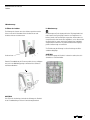
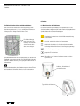
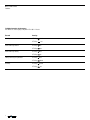
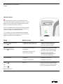
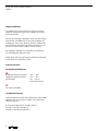
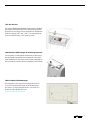
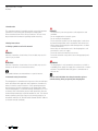
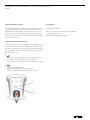
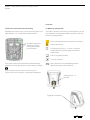
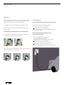
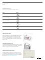
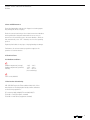
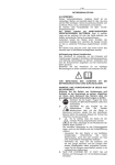
eMH2 Electric Mobile Home 2 Wallbox BEDIENUNGSANLEITUNG USER GUIDE eMH2 Ladebox 2 INHALT Contents 1 Einleitung 4 2 Sicherheitshinweise 2.1 Bedeutung der Sicherheitshinweise 4 4 2.2 Allgemeine Sicherheitshinweise 4 3 Allgemeine Kurzbeschreibung 3.1 Anzeigen und Bedienelemente 5 5 4 Komponenten 5 5 Wandmontage 5.1 Öffnen der Ladebox 5.2 Wandmontage 5.3 Elektrischer Anschluss und Inbetriebnahme 6 6 6 7 6 Funktion 6.1 Warnhinweise und Bedienung 7 7 7 Bedienung 7.1 Entnehmen des Ladesteckers aus der Ladebox 7.2 Ladevorgang Varianten mit integriertem Ladekabel und Stecker Varianten mit eingebauter Ladedose; Ladekabel extern 7.3 Ablauf normaler Ladevorgang 8 8 8 8 8 9 8 Betriebsstörungen 10 9 Pflege und Wartung 11 10 Technische Daten 10.1 Umgebungsbedingungen 11 11 11 Konformitätserklärung 11 English Operating Manual 12 Einleitung Ladebox 1 Einleitung Diese Bedienungsanleitung enthält wichtige Hinweise zum An schließen und zum sicheren Betrieb des Gerätes. Lesen und befolgen Sie unbedingt die angegebenen Sicherheitshinweise. Alle Sicherheitsbestimmungen sollten auch an andere Benutzer weitergegeben werden. 2 Sicherheitshinweise 2.1 Bedeutung der Sicherheitshinweise GEFAHR! Die Nichtbeachtung dieses Zeichens kann zur Gefährdung von Leib und Leben führen. ACHTUNG! Die Nichtbeachtung dieses Zeichens kann zu Schäden am Gerät oder an angeschlossenen Verbrauchern führen. Dieses Zeichen weist auf Empfehlungen oder Besonderheiten hin. Gefahr! · Die elektrische Anlage entspricht den geltenden Richtlinien und Normen · Keine Manipulationen an elektrischer Anlage vornehmen. · Keine Veränderungen am Gerät vornehmen. · Elektrischen Anschluss nur von dafür ausgebildetem Fachpersonal gemäß Bedienungsanleitung durchführen lassen. · Gerät nicht mit defekten Leitungen oder fehlerhaftem Anschluss in Betrieb nehmen. · Keine Wartungsarbeiten am Gerät durchführen, wenn Spannung anliegt. · Elektrische Anschlüsse sachgemäß durchführen. · Richtige elektrische Absicherung sicherstellen. ACHTUNG! · Die Ladebox ist ausschließlich für den Anschluss an eine 230 V oder 230 / 400 V Spannungsversorgung vorgesehen, die Versorgungsleitungen können unter oder auf Putz verlegt werden. Der Kabeleintritt in der Rückschale ist bevorzugt unten. Vor der Inbetriebnahme, dem Befestigen oder dem Öffnen der Ladebox Sicherheitshinweise lesen und beachten. 2.2 Allgemeine Sicherheitshinweise Das Gerät ist nach dem Stand der Technik und den anerkannten sicherheitstechnischen Regeln gebaut. Dennoch können Personen verletzt oder kann das Gerät beschädigt werden, wenn die Sicherheitshinweise in dieser Bedienungsanleitung nicht beachtet werden. Das Gerät nur in technisch einwandfreiem Zustand benutzen. Störungen, die die Sicherheit von Personen oder des Geräts beeinträchtigen, sofort von Fachpersonal beheben lassen. Fachpersonal im Sinne dieser Anleitung ist eine unterwiesene Fachkraft (nach BGV A3, DIN VDE 0105-100 und DIN VDE 1000-10 oder der jeweils gültigen Ländernormen). 3 Allgemeine Kurzbeschreibung / Komponenten Ladebox 3 Allgemeine Kurzbeschreibung 4 Komponenten Die Ladebox ermöglicht sicheres und bequemes Laden von Elektro fahrzeugen gemäß IEC 61851, Lademodus 3. In diesem Lademodus stellt die Ladebox sicher, dass eine Spannungs-Aufschaltung auf das Ladekabel erst dann erfolgt, wenn das Fahrzeug korrekt ange schlossen ist und die Maximalstromstärken angeglichen wurden. Durch in die Ladebox eingebaute Fehlerstrom- und Leitungsschutz schalter wird weitere Sicherheit gewährleistet. Zum Umfang der Ladebox gehören: 3.1 Anzeigen und Bedienelemente Die Anzeige des aktuellen Leistungszustands der Ladebox erfolgt mittels zweier leuchtender Ringe (a und b) oder bei Geräten mit ECO-Mode mittels dreier farbig beleuchteter Ringe (a, b und c). Bei der Geräteausführung mit ECO-Mode ist zusätzlich ein Taster (d) vorhanden, um wahlweise die ECO-Funktion zu- oder abzuschalten. a) · zeigt die Betriebsbereitschaft der Ladestation an · blinkt alle 5 sec. kurz: betriebsbereit · leuchtet nicht: nicht betriebsbereit oder Ladevorgang aktiv b) · zeigt den Ladevorgang an · leuchtet dauerhaft: Ladevorgang aktiv · blinkt: Ladung fahrzeugseitig beendet a) b) 4 a) Basisstation mit fest verbundenem Ladestecker oder Ladesteckdose b) Montage- und Bedienungsanleitung c) Bohrschablone Wandmontage Ladebox 5 Wandmontage 5.1 Öffnen der Ladebox Zur Montage des Gerätes muss das Gehäuse geöffnet werden. Hierzu ist der mit 4 Schrauben fixierte Steckereinsatz oder Steckdoseneinsatz zu demontieren. 5.2 Wandmontage Die Bohrungen zur Befestigung und für das Zuleitungskabel sind nach Kenntnis der Befestigungssituation vom Fachpersonal zu bohren, hierfür sind Zentrierungen vorgesehen. Insbesondere im unteren Bereich, dem Austritt des Ladekabels, ist für sicheren Halt der Rückschale zu sorgen, da hier die Zugkräfte des Ladekabels aufgenommen werden. Die rot gekennzeichneten Befestigungs punkte sind bevorzugt zu verwenden. Zur Erleichterung der Montage ist dieser Anleitung eine Bohr schablone beigefügt. Steckereinsatz Achtung: Bei der Befestigung des Rückteils ist darauf zu achten, dass die Schutzklasse II erhalten bleibt. Dann die Frontabdeckung im Einsatzausschnitt fassen, aufkippen und, wie in der Abbildung gezeigt vom Rückteil des Gehäuses nach oben abnehmen. Achtung: Die LED für die Leuchtringe sind nach der Montage des Rückteils in der Frontabdeckung zu fixieren. Kennzeichnung beachten. 5 Wandmontage / Funktion Ladebox 6 Funktion 5.3 Elektrischer Anschluss und Inbetriebnahme 6.1 Warnhinweise und Bedienung Das Anschluss der elektrischen Zuleitung erfolgt je nach Ausführung an den mit L1, L2, L3, und N gekennzeichneten Leitungen, die in Wago-Klemmen fixiert sind. Die auf dem Gehäuse der Ladebox (siehe Warnhinweise in der Steckeraufnahme und Typenschild auf der Rückseite) angebrachten Symbole haben die folgenden Bedeutungen. Die Kabelzuführung kann an den mit Zen trierungen versehenen Stellen einmal oben oder unten erfolgen. Zugehörige Informationen sind der Bedienungsanleitung zu entnehmen Vorsicht, gefährliche elektrische Spannungen elektrische Schutzklasse II, d.h. es besteht eine verstärkte Isolierung zwischen Netzstromkreis und Ausgangsspannung siehe Bedienungsanleitung geprüfte CE-Konformität Die Inbetriebnahme darf ausschließlich durch eine unterwiesene Fachkraft vorgenommen werden. Die DIN VDE 0105-100 und DIN VDE 1000-10 oder die jeweils gültigen Ländernormen sind zu beachten. Schutzklasse des Gerätes (geschützt gegen allseitiges Spritzwasser) Aufkleber „Warnhinweise“ auf der Innenseite Vor der Inbetriebnahme, der Wandmontage oder dem Öffnen der Ladebox die Sicherheitshinweise lesen und beachten. Typenschild seitlich innen 6 Bedienung Ladebox 7 Bedienung Ist die Ladebox fachgerecht an die Stromversorgung angeschlossen, erfolgt der Beginn des Ladevorgangs mit dem Anschließen des Ladesteckers in die fahrzeug- oder geräteseitige Ladesteckdose. 7.2 Ladevorgang Der Ladezyklus startet automatisch (siehe Ladevorgang). Eine Unterbrechung oder Beendigung des Ladevorganges erfolgt durch Ausstecken des Steckers auf der Fahrzeugseite. · Stecker aus der Ladestation entnehmen · Stecker in Fahrzeugsteckdose einstecken Ladevorgang startet automatisch · Stecker vom Fahrzeug trennen und in der Ladestation ablegen 7.1 Entnehmen des Ladesteckers aus der Ladebox Varianten mit eingebauter Ladedose; Ladekabel extern Ladestecker des Typ I können entnommen werden, indem bei gedrückt gehaltener Taste der Stecker in der angegeben Richtung entnommen wird. · Ladekabel in Fahrzeug-Steckdose und Ladestation stecken · Ladekabel wird in der Ladedose verriegelt Ladevorgang startet automatisch · Ladekabel vom Fahrzeug trennen Ladedose entriegelt automatisch · Ladekabel von der Ladestation trennen Varianten mit integriertem Ladekabel und Stecker Ladestecker des Typ II werden entnommen indem man den Stecker in der gezeigten Richtung anhebt und dann aus der Halterung herausnimmt. 7 Bedienung Ladebox 7.3 Ablauf normaler Ladevorgang Der Ablauf des Ladevorgangs entspricht IEC 61851-1 Mode 3 Zustand Anzeige Stand by LED Ring blinkt LED Ring aus Elektrofahrzeug erkannt Elektrofahrzeug Ladung Ladung fahrzeugseitig beendet Stand by 8 LED Ring an LED Ring aus LED Ring aus LED Ring an LED Ring aus LED Ring blinkt LED Ring blinkt LED Ring aus Betriebsstörungen Ladebox 8 Betriebsstörungen Bei Ausfall durch automatische Stromunterbrechung ist die unten dargestellte Klappe an der Gehäuse-Vorderfront zu öffnen und der ausgelöste Schutzschalter durch Betätigen des Hebels wieder in seine Arbeitsstellung zu versetzen. Sollte diese Maßnahme nicht helfen und der Fehlerstromschutz schalter löst erneut aus so liegt möglicherweise ein Defekt vor, der nur von Fachpersonal behoben werden kann. Es ist zu beachten, dass die Gewährleitung bei unsachgemäß ausgeführter Reparatur erlischt und ABL-Sursum nicht für die dadurch entstandenen Folgeschäden haftet. Störung Mögliche Ursache Abhilfe Ladevorgang startet nicht obwohl blinkt LED Ring · Ladekabel am Fahrzeug oder an der Ladebox nicht korrekt eingesteckt · Stecker am Fahrzeug und ggf an der Ladebox auf korrekten Sitz prüfen (ausstecken, wieder anstecken) Ladevorgang startet nicht, leuchtet nicht LED Ring · FI Schutzschalter der Ladebox hat ausgelöst · Stecker am Fahrzeug abstecken, Klappe der Ladebox öffnen, FI-Schutzschalter rückstellen; Stecker wieder einstecken · Vorgelagerte Sicherung in der Hausverteilung ausgelöst Keine LED Anzeige LED Ring und · Sicherungen der vorgelagerten Spannungsversorgung (in der Regel am Hausanschluss) überprüfen · LED defekt · Kundendienst informieren · Leitung zur LED fehlerhaft · Kundendienst informieren Fehlerfall Stecker vom Fahrzeug trennen und Laden wiederholen. Flls das Problem weiterhin besteht, den Kundendienst informieren. LED Ring blinken abwechselnd 9 Pflege und Wartung Ladebox 9 Pflege und Wartung Die Ladebox kann mit einem trockenen Tuch gereinigt werden. Scharfe Reinigungsmittel könnten zum Eintrüben von Anzeigen (LED-Anzeige) führen. Die unter der Deckklappe eingebauten Fehlerstrom- und Leitungs schutzschalter sind halbjährlich auf ihre Funktionsfähigkeit hin zu überprüfen. Hierzu ist die neben den Schaltern sichtbare Prüftaste zu betätigen, der Schalter fällt dann automatisch auf „Aus“. Per Hand ist er dann wieder in Arbeitsstellung zu bringen. Das eingebaute Ladekabel sollte regelmäßig auf Schadstellen oder Beschädigungen überprüft werden. Darüber hinaus gelten die jeweiligen gesetzlichen Bestimmungen für den Betrieb von elektrischen Geräten. 10 Technische Daten 10.1 Umgebungsbedingungen Umgebungstemperatur (Lagerung) -30°C … 40°C Umgebungstemperatur (Betrieb)-25°C … 40°C Luftfeuchtigkeit 10% … 95% rH (nicht kondensierend) 230 V oder 230 / 400VAC 11 Konfirmitätserklärung Hiermit bestätigt die Firma ABL SURSUM Bayerische Elektrozubehör GmbH & Co. KG, als Hersteller der Ladebox, die Einhaltung der folgenden Richtlinien: CE- Konformität 2006 / 95 / EG und 2004 / 108 / EG IEC 61851-1 2nd Edition (Grundnorm) IEC 61851-22 2nd Edition (Gerätenorm) 10 1 Ein / Aus-Schalter Das unter der Abdeckklappe befindliche Bedienelement ermöglicht das Beenden und Wieder-Starten des Ladevorgangs durch Betä tigung des auf der rechten Seite des Bedienfensters befindlichen Schalters (Stellung „0 OFF“ bzw. „I ON“). Der Ladevorgang kann nur in der Schalterstellung „I ON“ gestartet werden. 2 Abschließbare Abdeckklappe der Sicherungsautomaten Zur Vermeidung von unbefugtem Manipulieren der Ladestation kann der Zugang zu den Bedienelemente abgeschlossen werden (nicht vandalensicher!). Dem Gerät sind zwei Schlüssel beigelegt. Bei Verlust wenden Sie sich bitte an Ihren zuständigen Service-Betrieb. 3 Bohrschablone für Wandmontage Zeichnungsblatt 4 im Format DIN A2 ausgedruckt dient der Positionsfestlegung der Bohrungen für die Wandmontage des Gerätes. Die Befestigungsfläche muss eine Größe von mindestens 250 x 360 mm aufweisen! Download - www.abl-sursum.com 11 introduction Wallbox 1 Introduction This operating manual is intended to provide users with important information on installing and operating the charging box. Please read and follow all the safety instructions. All users must be provided with information regarding health and safety. 2 Safety Instructions 2.1 Safety symbols used in this manual Danger! Indicates a hazardous situation that, if not avoided, may result in serious injury or death. WARNING! Indicates a hazardous situation that, if not avoided, may result in damage to the device or connected consumers. DANGER! · The electrical system corresponds to valid regulations and standards. · Do not manipulate the electrical system. · Do not modify the charging box. · Ensure electrical connection of the charging box is carried out by trained and qualified staff in accordance with instructions. · Never operate the charging box with damaged wires or cables or faulty connections. · Never carry out maintenance tasks if the charging box is still connected to sources of supply. · Ensure all electrical connections are correct. · Ensure the electrical safety devices are working properly and are correct. Warning! · The charging box is only intended for connection to a 230V or 230/400V power supply; the supply lines can be flush or surface mounted. The preferred cable entry point is at the bottom of the rear unit. This symbol indicates recommendations or special features. 2.2 General safety instructions The charging box is manufactured using state-of-the-art techniques and in accordance with approved safety regulations. Nonetheless, always follow the safety instructions in this operating manual to prevent personal injuries and damage to the charging box. Make sure the charging box is in efficient working order before use. Ensu re that any faults which affect personal and operational safety are eliminated immediately by a qualified member of staff. This manual defines qualified service personnel as fully trained specialists (in accordance with BGV A3, DIN VDE 0105-100 and DIN VDE 1000-10 or relevant national standards). 12 Please read and follow the safety instructions prior to commissioning, fixing or opening the charging box. General Short Description /Components Wallbox 3 General Short Description 4 Components The charging box enables safe and convenient charging of electric vehicles in accordance with IEC 61851, charging mode 3. In this charging mode the charging box ensures that power is only swit ched on, if the vehicle has been connected correctly and current limits are set. Residual current circuit breakers and circuit breakers ensure further protection. The charging box includes: a) Base station with permanently connected charging plug or charging socket b) Installation and operating instructions 3.1 Display and operating elements The current power status of the charging box is displayed via two illuminated rings (a and b) and for charging boxes with ECO mode via three colour illuminated rings (a, b and c). An additional button (d) is provided for ECO mode charging boxes in order to switch the ECO function on or off. a) · displays the operational availability of the charging station · flashes briefly every 5 seconds: ready for operation · not illuminated: not ready for operation or charging cycle active b) · displays the charging cycle · illuminates permanently: charging cycle active · flashes: charging completed signalled by the vehicle a) b) 13 Wall installation Wallbox 5 Wall installation 5.1 Opening the charging box Open the housing to install the charging box correctly. Disassemble the 4 screws of the plug insert or the socket insert. 5.2 Wall installation Specialist staff familiar with the attachment situation should use the provided centring guides to drill the holes for attachment and the feed cable. Make sure the lower part of the rear unit is secured sufficiently, where the charging cable exists the box, as this section absorbs the forces created by cable. Preferably use the red attach ment points. A drilling template supplied with this manual facilitates installation. Plug insert Subsequently use the insert recess to lift up and remove the front cover from the rear unit as shown. Caution: Fix the LEDs for the illuminated rings in the front cover after installing the rear unit. Pay attention to the labelling. 14 Caution: Ensure that protection class II is still provided after installing the rear unit. Wall installation / FunCtion Wallbox 6 Function 5.3 Electrical connection and comissioning 6.1 Warnings and operation Depending on the actual version, connect the power supply to the cables marked L1, L2, L3 and N fixed in Wago terminals. The symbols specified on the housing of the charging box (see war ning information in the plug holder and the type plate on the rear) have the following meanings. Refer to the operating manual for respective information The cable can be routed at the points with the centring either from the top or the bottom. Caution high voltages Electrical protection class II, i.e. there is reinforced insulation between the main supply circuit and the output voltage Refer to the operating manual Tested CE conformity Comissioning should only be carried out by authorized and fully qualified staff. Always pay attention to relevant national standards. Ingress protection of the charging box (protected against water spray from any direction) Please read and follow the safety instructions prior to commissioning, wall installation or opening the charging box. ”Warning sticker“ on the inside Type plate inside the box 15 Operation Wallbox 7 Operation Once the charging box has been connected to the power supply, start the charging cycle by inserting the charging plug into the charging socket at the vehicle or the charging box. 7.2 Charging cycle The charging cycle starts automatically (see charging cycle). · Remove the plug from the charging station · Insert the plug into the vehicle socket Charging cycle starts automatically · Disconnect the plug from the vehicle and place it back in the charging station Interrupt or stop the charging cycle by disconnecting the plug from the vehicle. Versions with integrated charging cable and plug 7.1 Removing the charging plug from the charging box Remove a IEC Type I charging plug by pressing the button and extracting the plug in the displayed direction. Versions with integrated charging socket; external charging cable · Insert the charging cable in the vehicle socket and in the charging station · The charging cable is locked in the charging socket Charging cycle starts automatically · Disconnect the charging cable from the vehicle Charging socket unlocks automatically · Disconnect the charging cable from the charging station Remove a IEC Type II charging plug by lifting the plug as displayed and then extracting it from the holder. 16 operation Wallbox 7.3 Normal charging cycle The charging cycle corresponds to IEC 61851-1 Mode 3 Status Display Stand by LED LED Electric vehicle detected Electric vehicle charging Charging completed at the vehicle Stand by flashes off LED on LED off LED off LED on LED off LED flashes LED flashes LED off 1 Service procider switch Allows the recharge process to be interrupted by turning the switch located on the right hand side of the control panel to the „0 OFF“ position. To start the recharge process, the switch must be in the „1 ON“ position. Charging (normal & eco) can be started only in the position „1 ON“. 2 Lockable circuit breaker cover In order to prevent tampering, the charging station has a lockable controls cover (not vandalism-proof). The wallbox is supplied with two keys. If lost, please contact your service provider. 3 Drilling template for wall mounting Schematic drawing No. 4 printed in a size DIN A2 sheet serves as a template for determining the positions of the holes for wall mounting. The mounting surface must measure at least 250x360 mm (10"x15")! Download: www.abl-sursum.com 17 Troubleshooting Wallbox 8 Troubleshooting If an automatic power failure occurs, open the front cover shown below and use the lever to reset the tripped circuit breaker. If this is unsuccessful and the residual current circuit breaker trips again, there is probably a fault that can only be eliminated by trained and qualified personnel. Please note that the warranty will not apply if unauthorized repairs are carried out. ABL-SURSUM shall not be liable for any conse quential damages or losses. Fault Possible cause Remedy Charging cycle does not start even is flashing though the LED Charging cable not inserted correctly at the vehicle or at the charging box Check secure connection of the plug at the vehicle and, if necessary, at the charging box (disconnect, reconnect the plug) Charging cycle does not start even is not illuminated though the LED · Residual current circuit breaker of the charging box has tripped · Disconnect the plug at the vehicle, open the cover of the charging box, reset the residual circuit breaker; reconnect the plug · Upstream fuse in the house fuse box has blown No LED display LED and LED flash alternately 18 · Check the fuses of the upstream power supply (usually in the house fuse box) · LED defective · Contact the Customer Service Department · LED wire faulty · Contact the Customer Service Department Fault Disconnect the plug from the vehicle and repeat charging. If the problem occurs again, contact the Customer Service Department Care and Maintenance Wallbox 9 Care and Maintenance Clean the charging box with dry cloth. Aggressive cleaning agents may damage the finish of displays. Check the correct functioning of the residual current circuit breakers and circuit breakers integrated underneath the cover every six month. Press the test button next to the circuit breakers, which are then automatically set to ”OFF“. Manually reset it to the operating position. Regularly check cables for any signs of fraying, breakage or damage. Furthermore, the relevant statutory regulations apply for the operation of electrical devices. 10 Technical Data 10.1 Ambient conditions Ambient temperature (storage)-30°C … 40°C Ambient temperature (operation)-25°C … 40°C Humidity 10% … 95% rH (non-condensing) 230 V or 230 / 400VAC 11 Declaration of Conformity ABL SURSUM Bayerische Elektrozubehör GmbH & Co. KG as manufacterer of the charging box hereby confirms adherence to the following regulations: CE conformity 2006/ 2006/95/EG und 2004/108/EG IEC 61851-1 2nd Edition (basic standard) IEC 61851-22 2nd Edition (equipment standard) 19 Seit über 90 J a h r e n die Kom pe te n z beim Ver bi nden und Sich e r n von Strom – weltwei t Worl dwi de le a d e r sh ip in co nn e c ti ng and protectin g p o w e r – f o r ov e r 90 y ea rs Made in G er many ABL SU R SUM Bayerische Elektrozubehör GmbH & Co. KG Ottensooser Straße 22 91207 Lauf / Pegnitz Postfach 10 02 47 91192 Lauf / Pegnitz Telefon +49 (0) 9123 188-0 Telefax +49 (0) 9123 188-188 [email protected] www.abl-sursum.com 0301402 / 05.2012