1
Durchflusssensor
Flow sensor
SFAM
de
Bedienungsanleitung
en
Operating
instructions
756204
1103a
SFAM
Symbole/Symbols:
Warnung
Warning
Vorsicht
Caution
Einbau und Inbetriebnahme darf nur durch
Fachpersonal mit entsprechender Qualifikation gemäß dieser Bedienungsanleitung
durchgeführt werden.
Installation and commissioning may only be
performed in accordance with these instructions by technicians with appropriate qualifications.
Hinweis
Note
Umwelt
Antipollution
Zubehör
Accessories
Deutsch – Durchflusssensor SFAM . . . . . . . . . . . . . . . . . . . . . . . . . . . . . . . . . . . . . . . . . . . . . .
3
English – Flow sensor SFAM . . . . . . . . . . . . . . . . . . . . . . . . . . . . . . . . . . . . . . . . . . . . . . . . . . .
37
2
Festo – SFAM – 1103a
SFAM
Deutsch – Durchflusssensor SFAM
Inhaltsverzeichnis
1
Produktbeschreibung . . . . . . . . . . . . . . . . . . . . . . . . . . . . . . . . . . . . . . . . . . . . . . . . . . . . . .
5
1.1
1.2
Übersicht . . . . . . . . . . . . . . . . . . . . . . . . . . . . . . . . . . . . . . . . . . . . . . . . . . . . . . . . . . . . . . . .
Merkmale . . . . . . . . . . . . . . . . . . . . . . . . . . . . . . . . . . . . . . . . . . . . . . . . . . . . . . . . . . . . . . .
5
6
2
Funktion und Anwendung . . . . . . . . . . . . . . . . . . . . . . . . . . . . . . . . . . . . . . . . . . . . . . . . . .
7
2.1
2.2
Betriebszustände . . . . . . . . . . . . . . . . . . . . . . . . . . . . . . . . . . . . . . . . . . . . . . . . . . . . . . . . .
Funktionsumfang . . . . . . . . . . . . . . . . . . . . . . . . . . . . . . . . . . . . . . . . . . . . . . . . . . . . . . . . .
2.2.1 Schaltausgänge . . . . . . . . . . . . . . . . . . . . . . . . . . . . . . . . . . . . . . . . . . . . . . . . . . . . .
2.2.2 Farbumschlag . . . . . . . . . . . . . . . . . . . . . . . . . . . . . . . . . . . . . . . . . . . . . . . . . . . . . . .
2.2.3 Normbedingungen . . . . . . . . . . . . . . . . . . . . . . . . . . . . . . . . . . . . . . . . . . . . . . . . . . .
2.2.4 Analogfilter . . . . . . . . . . . . . . . . . . . . . . . . . . . . . . . . . . . . . . . . . . . . . . . . . . . . . . . .
2.2.5 Digitalfilter . . . . . . . . . . . . . . . . . . . . . . . . . . . . . . . . . . . . . . . . . . . . . . . . . . . . . . . . .
2.2.6 Sicherheitscode . . . . . . . . . . . . . . . . . . . . . . . . . . . . . . . . . . . . . . . . . . . . . . . . . . . . .
2.2.7 Min/Max Werte . . . . . . . . . . . . . . . . . . . . . . . . . . . . . . . . . . . . . . . . . . . . . . . . . . . . .
7
8
8
10
10
10
10
11
11
3
Voraussetzungen für den Produkteinsatz . . . . . . . . . . . . . . . . . . . . . . . . . . . . . . . . . . . . . .
11
4
Einbau . . . . . . . . . . . . . . . . . . . . . . . . . . . . . . . . . . . . . . . . . . . . . . . . . . . . . . . . . . . . . . . . . .
13
4.1
4.2
Einbau mechanisch und pneumatisch . . . . . . . . . . . . . . . . . . . . . . . . . . . . . . . . . . . . . . . . .
Elektrischer Anschluss . . . . . . . . . . . . . . . . . . . . . . . . . . . . . . . . . . . . . . . . . . . . . . . . . . . . .
13
14
5
Inbetriebnahme . . . . . . . . . . . . . . . . . . . . . . . . . . . . . . . . . . . . . . . . . . . . . . . . . . . . . . . . . .
15
5.1
5.2
5.3
5.4
5.5
Symbolik auf dem Display . . . . . . . . . . . . . . . . . . . . . . . . . . . . . . . . . . . . . . . . . . . . . . . . . . .
Symbolik zur Darstellung der Menüstruktur . . . . . . . . . . . . . . . . . . . . . . . . . . . . . . . . . . . . .
RUN-Modus . . . . . . . . . . . . . . . . . . . . . . . . . . . . . . . . . . . . . . . . . . . . . . . . . . . . . . . . . . . . . .
INFO- / SHOW-Modus . . . . . . . . . . . . . . . . . . . . . . . . . . . . . . . . . . . . . . . . . . . . . . . . . . . . . .
EDIT-Modus . . . . . . . . . . . . . . . . . . . . . . . . . . . . . . . . . . . . . . . . . . . . . . . . . . . . . . . . . . . . . .
5.5.1 EDIT-Modus starten . . . . . . . . . . . . . . . . . . . . . . . . . . . . . . . . . . . . . . . . . . . . . . . . . .
5.5.2 Schaltverhalten der Schaltausgänge einstellen . . . . . . . . . . . . . . . . . . . . . . . . . . . .
5.5.3 Spezialmenü [SPEC] einstellen . . . . . . . . . . . . . . . . . . . . . . . . . . . . . . . . . . . . . . . . .
TEACH-Modus . . . . . . . . . . . . . . . . . . . . . . . . . . . . . . . . . . . . . . . . . . . . . . . . . . . . . . . . . . . .
RECORDER-Modus . . . . . . . . . . . . . . . . . . . . . . . . . . . . . . . . . . . . . . . . . . . . . . . . . . . . . . . .
15
16
17
18
20
20
21
22
24
25
5.6
5.7
Festo – SFAM – 1103a Deutsch
3
SFAM
6
Bedienung und Betrieb . . . . . . . . . . . . . . . . . . . . . . . . . . . . . . . . . . . . . . . . . . . . . . . . . . . .
26
7
Wartung und Pflege . . . . . . . . . . . . . . . . . . . . . . . . . . . . . . . . . . . . . . . . . . . . . . . . . . . . . . .
26
8
Ausbau . . . . . . . . . . . . . . . . . . . . . . . . . . . . . . . . . . . . . . . . . . . . . . . . . . . . . . . . . . . . . . . . .
27
9
Störungsbeseitigung . . . . . . . . . . . . . . . . . . . . . . . . . . . . . . . . . . . . . . . . . . . . . . . . . . . . . .
27
10
Zubehör . . . . . . . . . . . . . . . . . . . . . . . . . . . . . . . . . . . . . . . . . . . . . . . . . . . . . . . . . . . . . . . . .
27
11
Technische Daten . . . . . . . . . . . . . . . . . . . . . . . . . . . . . . . . . . . . . . . . . . . . . . . . . . . . . . . . .
28
4
Festo – SFAM – 1103a Deutsch
SFAM
1
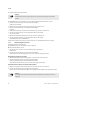
Produktbeschreibung
1.1
Übersicht
SFAM-62- … -T
SFAM-62- … -M
1
8
2
3
6
4
5
6
7
5
SFAM-90- … -M
SFAM-90- … -T
1
8
2
6
3
4
5
6
5
1
2
3
4
7
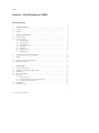
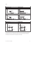
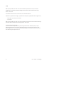
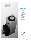
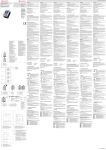
Display
B-Taste
Edit-Knopf
A-Taste
5
6
7
8
Stecker für elektrischen Anschluss
Druckluftanschluss
Siebpatrone
Einlaufstrecke
Fig. 1: Bedienteile und Anschlüsse
Festo – SFAM – 1103a Deutsch
5
SFAM
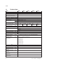
1.2
Merkmale
Merkmal
Bestellcode
Ausprägung
Typ
Rastermaß
SFAM
-62
-90
-10001)
-30001)
-5000
-100002)
-150002)
L
R
-M
-T
-W1)
G121)
N121)
G12)
N12)
G1122)
N1122)
-2SA
-2SV
-M12
-2.5S
-5S
-2.5A
-5A
Durchflusssensor
62 mm
90 mm
Max. 1000 l/min
Max. 3000 l/min
Max. 5000 l/min
Max. 10000 l/min
Max. 15000 l/min
unidirektional von links
unidirektional von rechts
Batteriemontage
Gewindemontage
Gewindemontage mit Wandbefestigung
G½
½” NPT
G1
1” NPT
G1½
1½” NPT
2x PNP oder NPN, 1 Analogausgang 4 … 20 mA
2x PNP oder NPN, 1 Analogausgang 0 … 10 V
Stecker M12x1, 5-polig, A-codiert
Verbindungsleitung, gerade Dose , Kabellänge 2,5 m
Verbindungsleitung, gerade Dose, Kabellänge 5 m
Verbindungsleitung, Winkeldose, Kabellänge 2,5 m
Verbindungsleitung, Winkeldose, Kabellänge 5 m
Durchflussmessbereich
Durchflusseingang
Befestigungsart
Pneumatischer Anschluss
Elektrischer Ausgang
Elektrischer Anschluss
Elektrisches Zubehör3)
1)
nur SFAM-62
2)
nur SFAM-90
3)
Im Lieferumfang enthalten.
Tab. 1: Variantenübersicht
6
Festo – SFAM – 1103a Deutsch
SFAM
2
Funktion und Anwendung
Der SFAM dient bestimmungsgemäß zur Überwachung von Durchfluss und Luftverbrauch / Luftvolumen
für geeignete Medien in Leitungssystemen oder Endgeräten in der Industrie; geeignete Medien
Kapitel 11 Technische Daten. Der konstruktive Aufbau ermöglicht den autarken Betrieb des
(SFAM-…-T) oder den Zusammenbau mit Wartungsgeräten der MS-Reihe (SFAM-…-M).
Bei der Messung wird ein thermisches Verfahren angewandt. Hierbei wird die Wärmemenge ermittelt,
die einer beheizten Fläche des Sensors durch das vorbeiströmende Medium entzogen wird. Über die
entzogene Wärmemenge wird der Durchfluss bzw. der Luftverbrauch ermittelt und am Display angezeigt. Die Anbindung an übergeordnete Systeme erfolgt über 2 Binärausgänge (Out A/B) und einen
Analogausgang (Out C). Für die Durchflussmessung sind Schaltpunkte für beide Binärausgänge einstellbar. Zur Luftverbrauchsmessung ist ein Verbrauchsschaltimpuls für Ausgang A (Out A) einstellbar.
Die Kombination Luftverbrauchsmessung (Out A) und Durchflussmessung (Out B) ist möglich. Über den
Analogausgang (Out C) wird der Durchflusswert weitergereicht.
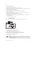
2.1
Betriebszustände
INFO-Modus
EDIT-Modus
TEACH-Modus
RECORDER-Modus
SHOW-Modus
Fig. 2: Betriebszustände des SFAM
RUN-Modus
Im RUN-Modus werden
– die Messwerte für Durchfluss (in l/min oder scfm)
– die Messwerte für den Luftverbrauch (in m³, scf oder l) und
– die Signalzustände der Schaltausgänge Out A, Out B (gesetzt, nicht gesetzt) angezeigt.
Festo – SFAM – 1103a Deutsch
7
SFAM
INFO-Modus
Im INFO-Modus kann bei aktivierter Luftverbrauchsmessung die Anzeige der Eingangsgrößen (Durchfluss, Luftverbrauch) im Display schnell umgeschaltet werden. Die Anzeige kann durch Drücken der
A-Taste oder der B-Taste umgeschaltet werden.
SHOW-Modus
Im SHOW-Modus werden die aktuellen Einstellungen für die Schaltausgänge Out A und Out B sowie die
Min/Max-Werte für die Durchfluss- oder Luftverbrauchsmessung angezeigt. Die Min/Max-Werte können
zurück gesetzt werden.
EDIT-Modus
Im EDIT-Modus können die Einstellungen für den Durchflusssensor (Schaltausgänge, Normbedingung,
Physikalische Einheit usw.) vorgenommen oder verändert werden.
TEACH-Modus
Im TEACH-Modus können die Schaltpunkte geteacht werden.
RECORDER-Modus
Im RECORDER-Modus kann eine manuelle Luftverbrauchsmessung durchgeführt werden.
2.2
Funktionsumfang
2.2.1
Schaltausgänge
Konfiguration der Schaltausgänge
Schaltausgang Out A:
kann entweder mit der physikalischen Eingangsgröße Durchfluss [FLW] oder der daraus abgeleiteten
Luftverbrauchsmessung [ConS] belegt werden.
Schaltausgang Out B:
kann nur mit der physikalischen Eingangsgröße Durchfluss verwendet werden.
Die Schaltausgänge Out A / Out B können entsprechend der Einstellbereiche in den Technischen Daten
Tab. 12: konfiguriert werden.
Für den Schaltausgang Out A und Out B können unabhängig voneinander die Schaltfunktion Schwellwert- oder Fenster-Komparator gewählt werden. Jedem Schaltausgang kann separat die Schaltelementfunktion Öffner (NC) oder Schließer (NO) zugeordnet werden, Tab. 2: .
Schaltpunkte [SP] und Hysterese [HY] können entsprechend der Einstellbereiche in der Tabelle
Technischen Daten Tab. 12: eingestellt werden.
8
Festo – SFAM – 1103a Deutsch
SFAM
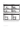
Schaltpunkt und Hysterese bei Durchflussmessung für Out A / Out B
Schwellwert-Komparator
Fenster-Komparator
Schaltelementfunktion NO (Schließer)
OUT
OUT
1
1
Hy
0
q
SP
[l/min]
Hy
0
Hy
SP Lo
SP Hi
q
[l/min]
q
[l/min]
Schaltelementfunktion NC (Öffner)
OUT
OUT
1
1
Hy
0
q
SP
[l/min]
Hy
0
Hy
SP Lo
SP Hi
Tab. 2: Einstellung Schaltpunkt SP und Hysterese Hy
Verbrauchsschaltimpuls [CI] bei Luftverbrauchsmessung
Einstellung NO (Schließer)
Einstellung NC (Öffner)
[l],
[m³]
[l],
[m³]
CI
t
0
OUT A
CI
t
0
OUT A
1
1
100 ms
0
CI
CI
t
100 ms
0
CI
CI
t
Tab. 3: Verbrauchsschaltimpuls
Mit dem Verbrauchsschaltimpuls [CI] kann ein Schwellwert für den Luftverbrauch eingestellt werden.
Wenn der eingestellte Schwellwert erreicht ist, dann wird am Ausgang Out A für 100 ms ein Schaltimpuls ausgegeben. Mit jedem Schaltimpuls wird die Messung des Luftverbrauchs von neuem gestartet.
Festo – SFAM – 1103a Deutsch
9
SFAM
2.2.2
Farbumschlag
Abhängig vom Schaltzustand kann für Out B ein Rot-Farbumschlag eingestellt werden. Somit kann der
Anlagenzustand über große Entfernungen visualisiert werden.
Folgende Einstellungen können gewählt werden:
r.On =
Display ist rot, wenn der Schaltausgang High (1) ist.
Display ist blau, wenn der Schaltausgang Low (0) ist.
r.OFF = Display rot, wenn der Schaltausgang Low (0) ist.
Display ist blau, wenn der Schaltausgang High (1) ist.
bLUE = Display ist blau, die Funktion Farbumschlag ist ausgeschaltet.
2.2.3
Normbedingungen
Der vom SFAM gemessene und ausgegebene Luftmassenstrom bezieht sich auf Normbedingungen.
Werksseitig ist der SFAM auf die physikalischen Normbedingungen nach DIN 1343 und die Einheit l/min
kalibriert.
Hinweis
Werden abweichend vom kalibrierten Messbereich mit der Einheit l/min andere Normbedingungen und / oder Einheiten verwendet, so ergeben sich für den Analogausgang
entsprechende Kennliniengrenzwerte Tab. 15: im Kapitel 11 Technische Daten.
Folgende Normbedingungen können unter dem Menüpunkt [Option], Kapitel 5.5.3 Spezialmenü
[SPEC] einstellen, ausgewählt werden.
Option
Off
1
2
Normliter nach
Luftdruck (absolut)
Temperatur
DIN 1343
1,01325
0
ISO 2533
1,01325
15
ISO 6358
1
20
[bar]
[°C]
Tab. 4: Normbedingungen
2.2.4
Analogfilter
Mit dem Analogfilter kann die Filterzeitkonstante aller Ausgangssignale verändert werden. Damit
verändert sich die Anstiegszeit am Analogausgang ( Fig. 3: ).
2.2.5
Digitalfilter
Mit dem Digitalfilter können die Anzeigewerte geglättet werden. Der Glättungsgrad kann in 6 Stufen
von d1 = geringe Glättung bis d6 = maximale Glättung eingestellt werden. Mit steigender Glättung
erhöht sich die Ein- / Ausschaltzeit der Schaltausgänge. Bei d.Off hängen die Schaltzeiten nur von der
eingestellten Filterzeitkonstante des Analogfilters ab ( Fig. 3: ).
10
Festo – SFAM – 1103a Deutsch
SFAM
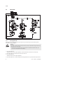
Signalfluss vom Analogfilter und Digitalfilter
Digitalfilter
Displayanzeige
Schaltausgänge
Out A/Out B
Sensor
Rohsignale
Analogfilter
Analogausgang
Fig. 3: Signalfluss vom Analogfilter und Digitalfilter
2.2.6
Sicherheitscode
Um die Einstellung vor unbefugten Zugriff zu schützen, kann ein bis zu 4-stelliger Zahlencode eingestellt werden. Der Sicherheitscode muss bei jeder Änderung der Einstellungen (EDIT-Modus und TEACHModus) eingegeben werden.
2.2.7
Min/Max Werte
Im SHOW-Modus können die Min/Max Werte für eine Durchflussmessung oder eine Luftverbrauchsmessung angezeigt und zurück gesetzt werden, Kapitel 5.4.
Hinweis
Das Ausschalten der Versorgungsspannung setzt die Min/Max Werte zurück.
3
Voraussetzungen für den Produkteinsatz
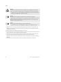
Warnung
Abhängig von der Funktionalität der Maschine / Anlage kann die Manipulation von Signalzuständen schwere Personenschäden verursachen.
• Berücksichtigen Sie, dass das Ändern des Schaltverhaltens der Ausgänge im EditModus sofort wirksam wird.
• Aktivieren Sie den Passwortschutz (Sicherheitscode), um das versehentliche Ändern
durch unbefugte Dritte zu verhindern Kapitel 5.5.3, Abschnitt Sicherheitscode
einstellen.
Warnung
Die Verwendung des Produkts in Verbindung mit unzulässigen Medien kann zu Personenschäden führen.
• Verwenden Sie es nicht in Verbindung mit entzündlichen Gasen, korrosiven Gasen,
Sauerstoff usw. Das Produkt ist nur zur Messung des Durchflusses von Medien vorgesehen, die im Kapitel 11 Daten als geeignet aufgeführt sind.
Festo – SFAM – 1103a Deutsch
11
SFAM
Vorsicht
Kondenswasser, Ölnebel, Fremdkörper und andere Verunreinigungen in der Druckluft
können das Produkt beschädigen und führen zu Messfehlern und Funktionsstörungen.
• Stellen Sie sicher, dass die vorgegebene Luftqualitätsklasse für das Betriebsmedium
eingehalten wird Kapitel 11 Technische Daten.
Hinweis
Das Produkt ist ausschließlich zum Einsatz für industrielle Zwecke geeignet.
In Wohnbereichen können Maßnahmen zur Funkentstörung notwendig sein. Es ist nicht
geeignet für Abrechnungszwecke im geschäftlichen Verkehr, z. B. zur Luftverbrauchszählung in Versorgungseinrichtungen.
Hinweis
Durch unsachgemäße Handhabung entstehen Fehlfunktionen.
• Stellen Sie sicher, dass die nachfolgenden Vorgaben stets eingehalten werden.
• Vergleichen Sie die Grenzwerte in dieser Bedienungsanleitung mit denen Ihres Einsatzfalls (z. B.
Betriebsmedium, Drücke, Kräfte, Momente, Temperaturen, Massen, Geschwindigkeiten, Betriebsspannungen, Durchflüsse).
• Berücksichtigen Sie die Umgebungsbedingungen am Einsatzort.
• Berücksichtigen Sie die Vorschriften der Berufsgenossenschaft, des Technischen Überwachungsvereins, des VDE oder entsprechende nationale Bestimmungen.
• Entfernen Sie die Transportvorkehrungen wie Schutzwachs, Folien (Polyamid), Kappen (Polyethylen), Kartonagen (außer den Verschlusselementen der pneumatischen Anschlüsse).
Die Verpackungen sind vorgesehen für eine Verwertung auf stofflicher Basis (Ausnahme: Ölpapier =
Restmüll).
• Verwenden Sie den Artikel im Originalzustand ohne jegliche eigenmächtige Veränderung.
12
Festo – SFAM – 1103a Deutsch
SFAM
4
Einbau
4.1
Einbau mechanisch und pneumatisch
Die Einbaulage ist waagerecht ±5 %. Befestigen Sie den SFAM wie folgt:
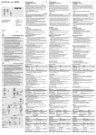
Fig. 4: Einbau mechanisch und pneumatisch
Hinweis
Informationen zur Montage von Modulverbinder, Anschlussplatte und Befestigungswinkel (Befestigungswinkel nur bei SFAM-62) finden Sie in der Bedienungsanleitung, die
dem Zubehör beigefügt ist.
Der Luftmassenstrom wird an dem Anschluss zugeführt, an dem sich die Siebpatrone (beim SFAM-…-M)
oder die Einlaufstrecke (beim SFAM-…-T/-W) befindet. Am gegenüberliegenden Anschluss wird der
Luftmassenstrom entnommen ( Fig. 4: ).
Mindestanforderungen pneumatischer Anschluss
In Abhängigkeit vom Rastermaß sind für den pneumatischen Anschluss folgende Mindestanforderungen einzuhalten:
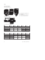
SFAM
Pneumatischer Anschluss MS-Baureihe
Innendurchmesser Zuleitung
[mm]
-62
-90
½”
¾”
10
20
Tab. 5: Mindestanforderungen pneumatischer Anschluss
Zusammenbau mit Wartungsgeräten der MS-Baureihe
Beim Zusammenbau mit einem bereits vorhandenen Wartungsgerät der MS-Baureihe:
1. Beachten Sie die Durchflussrichtung.
2. Installieren Sie den SFAM nur nach Wartungsgeräten, die den Filtrationsgrad (Luftqualitätsklasse
5.4.3.: 40 µm Reststaub, +3 °C Drucktaupunkt, 1 mg/m³ Restölgehalt) einhalten.
Festo – SFAM – 1103a Deutsch
13
SFAM
Hinweis
Die Druckluft darf keine Esteröle enthalten.
Hinweis
Der SFAM darf nicht direkt hinter einen Druckregler oder Filterregelventil eingebaut
werden, um die angegebenen Genauigkeiten einzuhalten.
• Bauen Sie nach einem Filterregelventil MS…-LFR oder Druckregelventil
MS…-LR ein Abzweigmodul vor dem SFAM ein.
– Rastermaß 62: MS…-FRM-½
– Rastermaß 90: MS…-FRM-¾
3. Platzieren Sie die Modulverbinder Typ MS…-MV in den Nuten der Einzelgeräte. Dabei ist zwischen
den Einzelgeräten eine Dichtung erforderlich.
4. Befestigen Sie die Modulverbinder Typ MS…-MV mit 2 Schrauben.
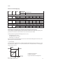
4.2
Elektrischer Anschluss
Warnung
Verwenden Sie ausschließlich Stromquellen, die eine sichere elektrische Trennung der
Betriebsspannung nach IEC/DIN EN 60204-1 gewährleisten. Berücksichtigen Sie zusätzlich die allgemeinen Anforderungen an PELV-Stromkreise gemäß IEC/DIN EN 60204-1.
Schaltnetzteile sind zulässig, wenn sie die sichere Trennung im Sinne der
EN 60950/VDE 0805 gewährleisten.
Hinweis
Lange Signalleitungen reduzieren die Störfestigkeit.
• Stellen Sie sicher, dass die Signalleitungen kürzer sind als 30 m.
Hinweis
Die Binärausgänge an Pin 2 und Pin 4 können je nach Bedarf als PNP oder NPN-Anschluss verdrahtet werden.
• Achten Sie darauf, dass Sie entsprechend Ihrer Verdrahtung auch die Binärausgänge
entsprechend konfigurieren Kapitel 5.5.3.
14
Festo – SFAM – 1103a Deutsch
SFAM
• Verdrahten Sie den SFAM wie folgt:
Pin
Belegung
Adernfarben1)
Stecker2)
1
DC +24 V Betriebsspannung
Braun (BN)
5-polig M12
2
Binärausgang B (Out B)
Weiß (WH)
3
0V
Blau (BU)
4
Binärausgang A (Out A)
Schwarz (BK)
5
Analogausgang C (Out C)3)
Grau (GY)
1
2
4
5
3
1)
Bei Verwendung der Verbindungsleitung aus dem elektrischen Zubehör Kapitel 1.2 Merkmale
2)
Anziehdrehmoment für Überwurfmutter am Stecker max. 0,5 Nm.
3)
Spannung U bzw. Strom I Kapitel 11 Technische Daten
Tab. 6: Pin-Belegung
Schaltbilder
SFAM-…-2SA
SFAM-…-2SV
Tab. 7: Schaltbilder SFAM
5
Inbetriebnahme
5.1
Symbolik auf dem Display
Symbolik
Beschreibung
Out A / Out B
Lock
Run
Option
Schaltausgang A / Schaltausgang B
Sicherheitscode ist aktiv (Sperrung gegen unbefugte Programmierung)
Luftverbrauchsmessung im Recordermodus ist aktiv.
Der Sensor ist auf eine von der Werkseinstellung abweichende Normbedingung
eingestellt.
Kapitel 5.5.3, Abschnitt Normbedingungen [Option] einstellen
Luftverbrauchsmesswert zurücksetzen
Schaltausgang gesetzt / nicht gesetzt
Stop
Schwellwert-Komparator
Fenster-Komparator
Schaltmodus Luftverbrauch (consumption - nur bei Out A)
Festo – SFAM – 1103a Deutsch
15
SFAM
Symbolik
Beschreibung
Schaltschwelle für Verbrauchsschaltimpuls (consumption impulse)
Schaltpunkt (switching point)
Unterer Schaltpunkt (switching point - low)
Oberer Schaltpunkt (switching point - high)
Hysterese
Schließer (normally open)
Öffner (normally closed)
Schaltmodus Durchfluss (flow - nur bei Out A)
Minimalwert Durchfluss (flow low)
Maximalwert Durchfluss (flow high)
Spezialmenü
Analogfilter
Digitalfilter
Display rot bei Schaltzustand ON bzw. logisch 1 (für Out B)
Display rot bei Schaltzustand OFF bzw. logisch 0 (für Out B)
Ausgang Plusschalter
Ausgang Nullschalter
Segmente leuchten: Grafische Anzeige des aktuellen Messwerts bezogen auf
den max. Messwert des Messbereichs
Lauflicht (1 Segment): Luftverbrauchsmessung für Out A oder RECORDER-Modus
aktiv
3 Segmente blinken: Hysteresewert wird angezeigt
1 Segment blinkt:
– Segment 6: Schaltpunkt SP oder SP.Lo wird angezeigt
– Segment 8: Schaltpunkt SP.Hi wird angezeigt
– Segment 1: Min. Durchfluss (F.Lo) wird angezeigt
– Segment 10: Max. Durchfluss (F.Hi) wird angezeigt
Tab. 8: Symbolik auf dem Display
5.2
Symbol
Symbolik zur Darstellung der Menüstruktur
Bedeutung
Automatische Rückkehr in den Grundzustand (RUN-Modus) nach Ablauf der
Überwachungszeit (hier 80 Sekunden)
Um manuell in den Grundzustand (RUN-Modus) zurückzukehren, 3 Sekunden
Edit-Knopf drücken
Durchfluss erzeugen (zum Teachen des Messwertes - hier Flow 1)
Symbol auf dem Display blinkt (hier Out B)
16
Festo – SFAM – 1103a Deutsch
SFAM
Symbol
Bedeutung
Sicherheitscode aktiv (Lock - Sperrung gegen unbefugte Programmierung)
Sicherheitscode inaktiv (Lock)
Taste (hier A-Taste) drücken
A-Taste oder B-Taste drücken. Dann wechselt der SFAM auf die durch die Pfeile
angezeigte Einstellung.
A-Taste und B-Taste gleichzeitig drücken
Taste (hier A-Taste) und EDIT-Knopf gleichzeitig drücken
A-Taste oder B-Taste drücken und damit den gewünschten Wert einstellen
kurzzeitige Anzeige (hier [AnA.F]) bedeutet, dass ein Wert angezeigt werden
kann.
Anzeige für einen Wert oder Schaltpunkt. Wert kann eingestellt werden.
Edit-Knopf drücken
Verzweigung im Menü
zeigt im SHOW-Modus die im EDIT-Modus letzte gewählte Einstellung
Tab. 9: Symbolik zur Darstellung der Menüstruktur
5.3
RUN-Modus
Im Grundzustand befindet sich das Produkt im RUN-Modus. Er werden die aktuellen Messwert angezeigt. Der Grundzustand kann aus anderen Modi erreicht werden durch:
– Edit-Knopf 3 Sekunden drücken oder
– Ablauf einer Überwachungszeit, Timeout
Im RUN-Modus werden
– die Messwerte für Durchfluss (in l/min oder scfm),
– die Messwerte für den Luftverbrauch (in m³, scf oder l) und
– die Signalzustände der Schaltausgänge Out A, Out B (gesetzt, nicht gesetzt) angezeigt.
1. Schalten Sie die Betriebsspannung ein.
Der SFAM befindet sich im RUN-Modus.
2. Prüfen Sie die Einstellungen des SFAM Kapitel 5.4 SHOW-Modus.
Hinweis
Ein blinkender Wert bedeutet, dass der Wert außerhalb des zulässigen Messbereichs
gemessen wurde.
Festo – SFAM – 1103a Deutsch
17
SFAM
5.4
1)
INFO- / SHOW-Modus
INFO-Modus nur bei aktivierter Verbrauchsmessung möglich
Fig. 5: SHOW-Modus
18
Festo – SFAM – 1103a Deutsch
SFAM
Im Show Modus werden je nach drücken der A-Taste oder B-Taste die aktuellen Einstellungen für die
Schaltausgänge Out A bzw. Out B angezeigt.
Der SFAM muss sich im RUN-Modus befinden.
• Bei aktivierter Luftverbrauchsmessung ermöglicht der INFO-Modus ein schnelles Umschalten der
Eingangsgrößen Durchfluss und Luftverbrauch im Display durch Drücken der A-Taste oder der
B-Taste.
Hinweis
Liegen Fehler vor, werden nach Drücken der A-Taste / B-Taste zuerst entsprechende
Fehlernummern angezeigt.
• Durch wiederholtes Drücken der A-Taste / B-Taste werden nacheinander die Einstellungen des jeweiligen Schaltausgangs angezeigt.
• Am Ende des SHOW-Modus werden der Min-Wert [F.Lo] und der Max-Wert [F.Hi] angezeigt. Wird kein
weiterer Tastendruck vorgenommen bleibt die Anzeige der Min / Max–Werte dauerhaft bestehen
(kein Timeout). Dabei wird durch das Blinken von Segment 1 oder Segment 10 im Bargraph die Minbzw. Max-Anzeige signalisiert Tab. 8: .
• Die Min / Max–Werte können durch Drücken des Edit-Knopfs zurückgesetzt werden.
• Wurden alle Einstellungen angezeigt, kehrt der SFAM nach nochmaligem Drücken der A-Taste /
B-Taste in den RUN-Modus zurück und zeigt den aktuellen Messwert für den entsprechenden Ausgang an.
Festo – SFAM – 1103a Deutsch
19
SFAM
5.5
EDIT-Modus
Fig. 6: EDIT-Modus
5.5.1
EDIT-Modus starten
Im EDIT-Modus können Sie Einstellungen für den Schaltausgang Out A den Schaltausgang Out B und
das Spezialmenü [Spec] konfigurieren.
Warnung
Abhängig von der Funktionalität der Maschine/Anlage kann die Manipulation von Signalzuständen schwere Personenschäden verursachen.
• Berücksichtigen Sie, dass das Ändern des Schaltverhaltens der Ausgänge im EDITModus sofort wirksam wird.
1. Drücken Sie den Edit-Knopf.
Der EDIT-Modus ist aktiv und [Out A] blinkt oder bei aktiver Sicherheitssperre blinkt [Lock].
2. Drücken Sie die A-/B-Tasten, bis der gewählte Sicherheitscode eingestellt ist.
3. Drücken Sie den Edit-Knopf.
Der EDIT-Modus ist aktiv und [Out A] blinkt.
4. Drücken Sie die A-/B-Tasten, um zwischen den Einstell-Modi für Out A, Out B und das Spezialmenü umzuschalten.
20
Festo – SFAM – 1103a Deutsch
SFAM
5.5.2
Schaltverhalten der Schaltausgänge einstellen
a) Durchflussüberwachung einstellen
Hinweis
Der Ablauf zum Einstellen der Schaltausgänge ist grundsätzlich gleich. Zusätzlich muss
für Out A der Schaltmodus [FLW] ausgewählt werden, da Out A auch zur Luftverbrauchsmessung konfiguriert werden kann. Für Out B kann zusätzlich der Farbumschlag für die
Anzeige eingestellt werden.
Nachfolgend wird der Ablauf anhand des Schaltausgangs Out A beschrieben.
Der SFAM befindet sich im EDIT-Modus und [Out A] blinkt, Abschnitt EDIT-Modus starten.
• Um Out A einzustellen gehen Sie wie folgt vor:
1. Drücken Sie den Edit-Knopf, um die Auswahl zu bestätigen.
[FLW] oder [ConS] blinkt.
2. Wählen Sie die Durchflussmessung (FLW) mit den A-/B-Tasten aus.
3. Drücken Sie den Edit-Knopf, um die Auswahl zu bestätigen.
Die aktuell eingestellte Schaltfunktion blinkt.
4. Wählen Sie die gewünschte Schaltfunktion mit den A-/B-Tasten aus.
5. Drücken Sie den Edit-Knopf, um die Auswahl zu bestätigen.
[SP] bzw. [SP.Lo] blinkt.
6. Stellen Sie den Schaltpunkt (SP bzw. SP.Lo) mit den A-/B-Tasten ein.
7. Drücken Sie den Edit-Knopf, um den eingestellten Wert zu bestätigen.
Nur bei Schaltfunktion Fenster-Komparator.
[SP.Hi] blinkt
• Stellen Sie den Wert (SP.Hi) mit den A-/B-Tasten ein.
• Drücken Sie den Edit-Knopf, um den eingestellten Wert zu bestätigen.
[Hy] blinkt.
8. Stellen Sie den Wert für die Hysterese (Hy) mit den A-/B-Tasten ein.
9. Drücken Sie den Edit-Knopf, um den eingestellten Wert zu bestätigen.
[no] oder [nc] blinkt.
10.Wählen Sie die Schaltelementfunktion (no/nc) mit den A-/B-Tasten aus.
11.Drücken Sie den Edit-Knopf, um den eingestellten Wert zu bestätigen.
Nur für Out B (Farbumschlag einstellen)
Hinweis
Wurde die Durchflussüberwachung für Out B konfiguriert, so kann nach der Konfiguration
der Schaltelementfunktion noch der Farbumschlag für das Display konfiguriert werden.
[rON], [rOFF] oder [bLUE] blinkt. Die Einstellung für den Farbumschlag kann konfiguriert werden.
12.Wählen Sie die gewünschte Einstellung (rON, rOFF oder bLUE) mit den A-/B-Tasten aus.
13.Drücken Sie den Edit-Knopf, um die Auswahl zu bestätigen.
Der SFAM befindet sich im RUN-Modus.
Prüfen Sie im Probelauf durch variieren des Durchflusses, ob der SFAM wie gewünscht schaltet (Schaltpunkte und Hysterese).
Festo – SFAM – 1103a Deutsch
21
SFAM
b) Verbrauchsüberwachung einstellen
Hinweis
Die Luftverbrauchsmessung [ConS] kann nur für den Schaltausgang Out A aktiviert
werden.
Der SFAM befindet sich im EDIT-Modus und [Out A] blinkt, Abschnitt EDIT-Modus starten.
1. Drücken Sie den Edit-Knopf, um die Auswahl zu bestätigen.
[FLW] oder [ConS] blinkt.
2. Wählen Sie die Luftverbrauchsmessung [ConS] mit den A-/B-Tasten aus.
3. Drücken Sie den Edit-Knopf, um die Auswahl zu bestätigen.
[CI] blinkt.
4. Stellen Sie den Wert für den Verbrauchsschaltimpuls (CI) mit den A-/B-Tasten ein.
5. Drücken Sie den Edit-Knopf, um den eingestellten Wert zu bestätigen.
[no] oder [nc] blinkt.
6. Wählen Sie die Schaltelementfunktion (no/nc) mit den A-/B-Tasten aus.
7. Drücken Sie den Edit-Knopf, um den eingestellten Wert zu bestätigen.
Der SFAM befindet sich im RUN-Modus
Prüfen Sie im Probelauf durch variieren des Durchflusses, ob der SFAM wie gewünscht schaltet.
5.5.3
Spezialmenü [SPEC] einstellen
So gelangen Sie in das Spezialmenü:
Der SFAM befindet sich im EDIT-Modus und [Out A] blinkt,
Abschnitt EDIT-Modus starten.
1. Drücken Sie die A- oder B-Taste, bis das Menü (SPEC) ausgewählt ist.
[SPEC] blinkt.
2. Drücken Sie den Edit-Knopf, um die Auswahl zu bestätigen.
[Option] blinkt, die Normbedingungen (OFF, 1 oder 2) können eingestellt werden.
Normbedingungen [Option] einstellen
3. Wählen Sie die gewünschte Einstellung (OFF, 1 oder 2)mit den A-/B-Tasten aus.
4. Drücken Sie den Edit-Knopf, um die Auswahl zu bestätigen.
[FLW] wird angezeigt und der aktuell gewählte Wert blinkt.
Die Einheit für den Durchfluss (l/min oder scfm) kann eingestellt werden.
Physikalische Einheit für den Durchfluss [FLW] einstellen
5. Wählen Sie die gewünschte Einstellung (l/min oder scfm) mit den A-/B-Tasten aus.
6. Drücken Sie den Edit-Knopf, um die Auswahl zu bestätigen.
[AnA.F] und der aktuell eingestellte Wert wird angezeigt. Der Analogfilter kann eingestellt werden.
Hinweis
Die konfigurierte physikalische Einheit wird im RUN-Modus im Display unten rechts
angezeigt.
22
Festo – SFAM – 1103a Deutsch
SFAM
Analogfilter [AnA.F] einstellen
7. Wählen Sie den Wert für die Filterzeitkonstante (15 ms, 30 ms, 60 ms, 125 ms, 250 ms, 500 ms oder
999 ms) mit den A-/B-Tasten aus.
8. Drücken Sie den Edit-Knopf, um den eingestellten Wert zu bestätigen.
[dIG.F] und der aktuell gewählte Wert blinkt. Der Digitalfilter kann eingestellt werden.
Glättung für den Digitalfilter [diGF] einstellen
Hinweis
Durch eine hohe Filterzeitkonstante und eine hohe Glättung kann es zu einer Schaltzeit
von mehreren Sekunden kommen.
9. Wählen Sie den Wert für die Dämpfung (d1 bis d6 oder d.OFF) mit den A-/B-Tasten aus.
10.Drücken Sie den Edit-Knopf, um den eingestellten Wert zu bestätigen.
[ConS] wird angezeigt und der aktuell gewählte Wert blinkt.
Die Einheit für den Luftverbrauch (m3, scf oder l) kann eingestellt werden.
Physikalische Einheit für den Luftverbrauch [ConS] einstellen
11.Wählen Sie die gewünschte Einstellung (m3, scf oder l) mit den A-/B-Tasten aus.
12.Drücken Sie den Edit-Knopf, um die Auswahl zu bestätigen.
Der aktuell eingestellte Wert [PnP] oder [nPn] für den Schaltelementausgang blinkt. Der Schaltelementausgang kann eingestellt werden.
Schaltausgangscharakteristik [PnP] oder [nPn] einstellen
13.Wählen Sie die gewünschte Einstellung (PNP oder NPN) mit den A-/B-Tasten aus.
14.Drücken Sie den Edit-Knopf, um die Auswahl zu bestätigen.
[Lock] blinkt. Die aktuelle Einstellung wird angezeigt.
Sicherheitscode einstellen
Hinweis
Sicherheitscode wiederauffindbar hinterlegen. Bei vergessenen Sicherheitscode Kapitel 6,
Abschnitt SFAM auf Werkseinstellung zurücksetzen.
15.Wählen Sie mit den A-/B-Tasten zwischen einem inaktiven Sicherheitscode (OFF) oder einem maximal 4-stelligen Sicherheitscode.
16.Drücken Sie den Edit-Knopf, um die Auswahl zu bestätigen.
Der SFAM befindet sich im RUN-Modus.
Festo – SFAM – 1103a Deutsch
23
SFAM
5.6
TEACH-Modus
Hinweis
Der Ablauf zum Teachen der Schaltausgänge Out A (A-Taste) und Out B (B-Taste) ist
gleich. Nachfolgend wird der Ablauf anhand des Schaltausgangs Out A beschrieben.
Fig. 7: TEACH-Modus
Im TEACH-Modus können die Schaltpunkte für die Durchflussüberwachung eingelernt werden.
1. Wählen Sie vor dem Teachen im EDIT-Modus die gewünschte Schaltfunktion (Schwellwert- oder
Fenster-Komparator) aus Kapitel 5.5. EDIT-Modus.
Schwellwert-Komparator
Fenster-Komparator
Der (geteachte) Schaltpunkt ergibt
sich aus dem Mittelwert beider
Messwerte
SP = 1/2(Flow 1 + Flow 2)
Sonderfall: SP = Flow 1 = Flow 2
Das geteachte Schaltfenster ergibt sich aus den Messwerten:
SP.Lo = Flow 1
SP.Hi = Flow 2
Tab. 10: Schaltgröße einstellen
24
Festo – SFAM – 1103a Deutsch
SFAM
Zum Teachen der Schaltgrößen:
2. Erzeugen Sie einen Durchfluss (Flow 1)
3. Drücken Sie zuerst die A-Taste und dann zusätzlich den Edit-Knopf.
[Out A] und Balkenanzeige blinken und der Messwert wird als erster Teach-Punkt übernommen oder
bei aktiver Sicherheitssperre blinkt [Lock].
Nur bei aktiver Sicherheitssperre [Lock] (Punkte 4 und 5):
4. Drücken Sie die A-/B-Tasten, bis der gewählte Sicherheitscode eingestellt ist.
5. Drücken Sie den Edit-Knopf.
[Out A] und Balkenanzeige blinken und der Messwert wird als erster Teach-Punkt übernommen.
6. Erzeugen Sie einen zweiten Durchfluss (Flow 2).
7. Drücken Sie zuerst die A-Taste und dann zusätzlich den Edit-Knopf.
Der zweite Teach-Punkt wird übernommen und der Schaltpunkt (SP) oder die Schaltpunkte (SP.Lo
und SP.Hi) werden gültig.
Der SFAM befindet sich im RUN-Modus.
5.7
RECORDER-Modus
Im RECORDER-Modus kann eine manuelle Luftverbrauchsmessung durchgeführt werden.
Fig. 8: RECORDER-Modus
1. Drücken Sie die A-Taste und B-Taste gleichzeitig.
Der SFAM befindet sich im RECORDER-Modus
Der Status der Messung [Run] oder [Stop] wird angezeigt.
2. Durch Drücken der A-Taste können Sie die Messung starten oder stoppen.
3. Durch Drücken der B-Taste können Sie die Messung auf Null zurücksetzen.
4. Drücken Sie die A-Taste und B-Taste gleichzeitig.
Der SFAM befindet sich im RUN-Modus.
Hinweis
Wird der RECORDER-Modus bei laufender Messung [Run] verlassen so wird die Messung
im Hintergrund weitergeführt.
Festo – SFAM – 1103a Deutsch
25
SFAM
6
Bedienung und Betrieb
Vorsicht
Zu hohe Eigenerwärmung zerstört den SFAM.
• Vermeiden Sie hohe Taktfrequenzen bei großen Druckamplituden. Andernfalls werden die zulässigen Grenztemperaturen der verwendeten Materialien überschritten.
Der vom SFAM angezeigte Luftmassenstrom bezieht sich auf die Normbedingungen, die im Spezialmenü unter Optionen eingestellt wurden.
Beim Vergleich von Volumenströmen:
• Stellen Sie sicher, dass sich die zu vergleichenden Volumenströme (z. B. Betriebsvolumenstrom,
Liefermenge eines Kompressors, Messwerte eines Durchflusssensors von einem anderen Hersteller)
auf dieselben Ausgangsbedingungen beziehen.
• Nach dem Einschalten der Versorgungsspannung braucht der SFAM eine Aufwärmzeit von 5 Minuten, bis er die spezifizierte Genauigkeit einhält.
SFAM auf Werkseinstellung zurücksetzen
(auch bei nicht wiederauffindbarem Sicherheitscode)
Hinweis
Durch das Rücksetzen auf Werkseinstellung gehen die aktuellen Einstellungen verloren.
Notieren Sie bei Bedarf diese Einstellungen vor dem Rücksetzen.
Um den SFAM auf Werkseinstellung zurückzusetzen gehen Sie wie folgt vor:
1. Schalten Sie die Betriebsspannung aus.
2. Drücken Sie alle drei Einstellelemente gleichzeitig (A-Taste + B-Tasten + Edit-Knopf ) und halten sie
gedrückt.
3. Schalten Sie die Betriebsspannung wieder ein.
Der SFAM befindet sich im RUN-Modus.
7
Wartung und Pflege
• Schalten Sie zur äußeren Reinigung folgende Energiequellen ab:
– Betriebsspannung
– Druckluft.
• Reinigen Sie bei Bedarf den SFAM von außen.
Zulässige Reinigungsmedien sind Seifenlauge (max. +60 °C), Waschbenzin und alle werkstoffschonenden Medien.
26
Festo – SFAM – 1103a Deutsch
SFAM
8
Ausbau
1. Schalten Sie vor dem Ausbau folgende Energiequellen ab:
– Betriebsspannung
– Druckluft
2. Trennen Sie die jeweiligen Anschlüsse vom SFAM.
9
Störungsbeseitigung
Störung
mögliche Ursache
Abhilfe
Falsche Messwertanzeige
SFAM mit unzulässigem Medium betrieben
SFAM verschmutzt
Messung außerhalb des zulässigen
Messbereichs
SFAM nur mit zulässigen Medien betreiben
Gerät erneuern
Genauigkeit bezieht sich nur auf den
zulässigen Messbereich
Messbereichsendwert wurde mindestens einmal überschritten. Spezifizierte Genauigkeit kann daher wahrscheinlich nicht eingehalten werden
Kurzschluss / Überlast am entsprechenden Ausgang
Sicherstellen, dass Messbereichsendwert nicht überschritten wird
Zugriffsschutz aktiv
Sicherheitscode eingeben
Messbereichsüberschreitung (wird im
RUN-Modus angezeigt)
Gerät defekt
Messbereichsunterschreitung (wird im
SHOW-Modus angezeigt)
Messbereichsüberschreitung (wird im
SHOW-Modus angezeigt)
Unterspannung
Einsatzbedingungen überprüfen
Bei Durchflussmessung:
Messwert wird blinkend dargestellt
Bei Luftverbrauchsmessung:
Messwert wird blinkend dargestellt
Ausgänge schalten
nicht entsprechend
der Einstellung
Einstellungen nicht
editierbar (Lock)
O.FLO
Er1, Er2, Er4
Er9
Er10
Er17
Kurzschluss / Überlast beseitigen
Gerät erneuern
Einsatzbedingungen überprüfen
Einsatzbedingungen überprüfen
Betriebsspannung einhalten
Elektrische Verdrahtung überprüfen
Tab. 11: Störungsbeseitigung
10
Zubehör
Wählen Sie bitte das entsprechende Zubehör aus unserem Katalog.
www.festo.com/catalogue/sfam
Festo – SFAM – 1103a Deutsch
27
SFAM
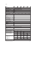
11
Technische Daten
SFAM
-1000
Allgemein
Zulassung
CE-Zeichen ( Konformitätserklärung)
Werkstoff-Hinweis
Eingangssignal / Messelement
Messgröße
Strömungsrichtung
-L
-R
Messprinzip
Durchflussmessbereich [l/min]
-3000
-5000
-10000
-15000
100 …
10000
150 …
15000
C-Tick
nach EU-EMV-Richtlinie
RoHS konform
Durchfluss, Luftverbrauch
unidirektional P1 } P2
unidirektional P1 { P2
thermisch
10 … 1000 30 … 3000 50 … 5000
Betriebsdruck
Nenndruck
Betriebsmedium
[bar]
[bar]
Mediumstemperatur
Umgebungstemperatur
Nenntemperatur
Signalverarbeitung
Filterzeitkonstante
(Analogfilter)
Filterzeitkonstante
(Digitalfilter)
[°C]
[°C]
[°C]
0 … 16
6
Luftqualitätsklasse 5:4:3 nach DIN ISO 8573-1
Stickstoff
0 … 50
0 … 50
23
[ms]
15, 30, 60 (Werkseinstellung), 125, 250, 500, 999 einstellbar
[ms]
d.OFF, d1 … d6 (Werkseinstellung: d3)
d1: ca. 20
d2: ca. 40
d3: ca. 80
d4: ca. 160
d5: ca. 320
d6: ca. 640
[%]
0,3
[%]
[%]
3
0,2
[%]
0,8
[%]
typ. 0,1
[%]
0,5
Ausgang allgemein1) 2)
Genauigkeit Nullpunkt
±FS
Genauigkeit Spanne ±FS
Wiederholgenauigkeit
Nullpunkt ±FS
Wiederholgenauigkeit
Spanne ±FS
Temperaturkoeffizient
Spanne ±FS/K
Druckabhängigkeit
Spanne ±FS/bar
28
Festo – SFAM – 1103a Deutsch
SFAM
SFAM
Schaltausgang
Schaltausgang
Schaltfunktion
Schaltelementfunktion
Max. Ausgangsstrom
[mA]
Spannungsfall
[V]
Induktive Schutzbeschaltung
Analogausgang
Durchflusskennlinie
[l/min]
Ausgangskennlinie
[mA]
Strom
Ausgangskennlinie
[V]
Spannung
Max. Lastwiderstand
[Ohm]
am Stromausgang
Min. Lastwiderstand am [kOhm]
Spannungsausgang
Ausgang, weitere Daten
Kurzschlussfestigkeit
Überlastfestigkeit
Elektronik
Betriebsspannungs[V]
bereich DC
Verpolungsschutz
Elektromechanik
Elektrischer Anschluss
Max. Länge Anschluss- [m]
leitung
Mechanik
Einbaulage
Pneumatischer Anschluss
Rastermaß 62 für SFAM-…-T
Pneumatischer Anschluss
Rastermaß 90 für SFAM-…-T
Produktgewicht
[g]
– SFAM-62-…-M
– SFAM-62-…-T
– SFAM-92-…-M
– SFAM-92-…-T
Werkstoff-Info Gehäuse
Festo – SFAM – 1103a Deutsch
-1000
-3000
-5000
-10000
-15000
2x PNP oder 2x NPN, einstellbar
Fenster-Komparator oder Schwellwert-Komparator, einstellbar
Öffner oder Schließer, einstellbar
100
max. 1,5
angepasst MZ, MY, ME-Spulen
0 … 1000
4 … 20
0 … 3000
0 … 5000
0 … 10000
0 … 15000
–
–
G1
NPT1
G1½
NPT1½
G1
NPT1
G1½
NPT1½
–
–
1500
2750
–
–
1500
2750
0 … 10
500
10
ja
vorhanden
15 … 30
für alle elektrischen Anschlüsse
Stecker gerade, M12x1, 5-polig
<30
waagerecht ±5°
G½
G½
NPT½
NPT½
–
–
–
–
–
–
–
–
G½
NPT½
G1
NPT1
G1½
NPT1½
600
600
600
1100
1100
1100
–
–
1500
–
–
2400
Polyamid verstärkt / Alu Druckguss
29
SFAM
SFAM
Anzeige / Bedienung
Anzeigeart
Darstellbare Einheiten
Einstellbereich Schwellwert
Durchfluss
Einstellbereich Schwell- [l]
wert Verbrauchsimpuls
[m3]
[scf ]
Einstellbereich Hysterese
Immission / Emission
Lagertemperatur
[°C]
Schutzart
Druckabfall3)
[mbar]
Schutzklasse
1)
-1000
-3000
-5000
-10000
-15000
10 …
19999
15 …
19999
30 …
19999
50 …
19999
1 … 19999
0,1 …
0,4 …
1999,9
1999,9
0%FS … 90%FS
0,5 …
1999,9
1 … 1999,9
2 … 1999,9
Leucht-LCD, blau
l/min, scfm,
l, m3, scf
1%FS … 100%FS
3 … 19999
–20 … +80
IP65
< 100
III
< 200
Genauigkeit bei Nennbedingungen (6 bar, 23 °C und waagerechter Einbaulage)
2)
% FS = % des Messbereichsendwertes (Fullscale)
3)
Gemessen bei einem Durchfluss 50%FS
Tab. 12: Technische Daten
Durchflussmessbereich1) qn in Abhängigkeit vom Betriebsdruck p
Fig. 9: Spezifischer Durchflussbereich
1)
30
Innerhalb der Durchflussmessbereichs gelten die Genauigkeitsspezifikationen gemäß Tab. 12:
Festo – SFAM – 1103a Deutsch
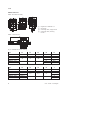
SFAM
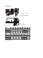
Abmessungen SFAM-62
Batteriemontage SFAM-…-M
1
2
3
4
Stecker M12x1 nach EN 60947-5-2
LCD-Anzeige
Verbindungsleitung, gerade Dose
Verbindungsleitung, Winkeldose
5
6
Einlaufstrecke
Wandbefestigung (nur bei Befestigungsart -W)
Gewindemontage SFAM-62-…-T/W
Fig. 10: Maßzeichnung
Typ
B1
B2
B3
B4
B5
B6
B7
D1
SFAM-62-…-M
62
31
78,7
–
–
–
–
–
SFAM-62-…-TG12
SFAM-62-…-WG12
SFAM-62-…-TN12
SFAM-62-…-WN12
62
31
78,7
277
40
31
78,7
277
40
–
4,5
–
4,5
G½
62
–
61,9
–
61,9
Typ
D3
H1
H2
H4
H5
H6
ß
–
63,5
62,1
80
–
–
–
63,5
62,1
80
63,5
62,1
80
–
71
–
71
–
6,6
–
6,6
SFAM-62-…-M
SFAM-62-…-TG12
SFAM-62-…-WG12
SFAM-62-…-TN12
SFAM-62-…-WN12
G¾
NPT¾
NPT½
26
26
Tab. 13: Maßtabelle SFAM-62
Festo – SFAM – 1103a Deutsch
31
SFAM
Abmessungen SFAM-90
Batteriemontage SFAM-…-M
1
2
3
4
Stecker M12x1 nach EN 60947-5-2
LCD-Anzeige
Verbindungsleitung, gerade Dose
Verbindungsleitung, Winkeldose
Gewindemontage SFAM-…-T
Fig. 11: Maßzeichnung SFAM-90
Typ
B1
B2
B3
B4
D1
SFAM-90-…-M
90
45
109
–
–
90
45
109
90
45
109
267
301
267
301
G1
G1½
NPT1
NPT1½
SFAM-90-…-TG1
SFAM-90-…-TG112
SFAM-90-…-TN12
SFAM-90-…-TN112
Typ
SFAM-90-…-M
SFAM-90-…-TG1
SFAM-90-…-TG112
SFAM-90-…-TN12
SFAM-90-…-TN112
D3
H1
H2
H4
ß
–
76,5
81,3
93
–
76,5
81,3
93
76,5
81,3
93
G1½
G2
NPT1½
NPT2
41
55
41
55
Tab. 14: Maßtabelle SFAM-90
32
Festo – SFAM – 1103a Deutsch
SFAM
Kennlinie für den Analogausgang
Option
Faktor
Einheit
Analogausgang
0 V oder 4 mA 10 V oder 20 mA
untere Grenze obere Grenze
Normbedingungen nach DIN 1343 (1,01325 bar, 0 °C)
OFF
1
[l/min]
0
1000
[scfm]
0
35,31
3000
105,9
5000
176,6
10000
353,1
15000
529,7
Normbedingungen nach ISO 2533 (1,01325 bar, 15 °C)
1
1,055
[l/min]
0
1055
[scfm]
0
37,25
3165
111,8
5275
186,3
10550
372,5
15825
558,8
Normbedingungen nach ISO 6358 (1 bar, 20 °C)
2
1,087
[l/min]
0
1087
[scfm]
0
38,38
3261
115,15
5435
191,91
10870
383,8
16305
575,7
Tab. 15: Kennlinie für den Analogausgang
Rechenbeispiele zur Berechnung der maximal auftretenden Kennlinienabweichung:
In der Anzeige eines SFAM-1000U wird für den Durchfluss ein Messwert von 600 l/min angezeigt. Wie
groß kann der tatsächliche, wahre Durchfluss sein, der durch den Sensor fließt?
Gemäß Spezifikation gilt bei Nennbedingungen (6 bar, 23°C):
– Genauigkeit Spanne: ±3%FS
– Genauigkeit Nullpunkt: ±0,3%FS.
– (im Beispiel: FS = 1000 l/min)
Der Gesamtfehler bei Nennbedingungen setzt sich aus diesen beiden Fehlergrößen zusammen, die im
folgenden getrennt betrachtet werden.
a) Spannenfehler
Ein Spannenfehler des Messsignals (= Fehler der Steigung der Kennlinie) wirkt sich stärker aus, je größer der Messwert ist ( Fig. 12: ). Ein Spannenfehler kann auch als Empfindlichkeits- oder Steigungsfehler bezeichnet werden.
y
z
x
x = Messgröße (Durchfluss)
y = Messwert (Anzeige)
z = gesuchter Fehler des Anzeigewertes
Fig. 12: Spannenfehler
Festo – SFAM – 1103a Deutsch
33
SFAM
Der maximale Fehler ergibt sich beim größten Messwert Fullscale (im Beispiel FS = 1000 l/min). Laut
Spezifikation ist der Fehler mit ±3%FS angegeben.
Der maximale Fehler errechnet sich wie folgt:
±3%FS = ±3% x 1000 l/min =±3/100 x 1000 l/min = ±30,00 l/min
Bei einem angezeigten Messwert von 600 l/min errechnet sich somit der maximale Spannenfehler wie
folgt:
±30 l/min × (600 l/min)/(1000 l/min)= ±18 l/min
Bei einer Anzeige von 600 l/min am Sensor kann aufgrund des Spannenfehlers der tatsächliche Durchfluss durch den Sensor Werte im Bereich 582 … 618 l/min haben.
Neben dem Spannenfehler muss noch der Nullpunktfehler berücksichtigt werden.
b) Nullpunktfehler
Ein Nullpunktfehler des Messsignals wirkt sich an jedem Punkt der Kennlinie gleichermaßen aus, d.h. er
ist unabhängig vom betrachteten Messwert ( Fig. 13: ).
y
z
x
x = Messgröße (Durchfluss)
y = Messwert (Anzeige)
z = gesuchter Fehler des Anzeigewertes
Fig. 13: Nullpunktfehler
Der Fehler ist laut Spezifikation mit ±0,3%FS angegeben. In unserem Fall entspricht FS = 1000 l/min.
Der Fehler errechnet sich wie folgt:
±0,3%FS = ±0,3/100 x 1000 l/min = ±3 l/min
Bei einer Anzeige von 600 l/min am Sensor kann aufgrund des Nullpunktfehlers der tatsächliche Durchfluss durch den Sensor Werte im Bereich 597 … 603 l/min haben.
34
Festo – SFAM – 1103a Deutsch
SFAM
c) Gesamtfehler bei Nennbedingungen
Für den Gesamtfehler bei Nennbedingungen müssen die Fehler Spanne mit ±18,00 l/min und Nullpunkt
mit ±3,00 l/min addiert werden, so dass sich bei 600 l/min der folgende Gesamtfehler ergibt:
600 l/min ±21,00 l/min
Bei einer Anzeige von 600 l/min am Sensor kann der tatsächliche Durchfluss durch den Sensor Werte
im Bereich 579 … 621 l/min haben.
d) Temperaturfehler
Wird der Sensor nicht bei Nennbedingungen(6 bar, 23°C) betrieben z. B. bei einem Druck von 6 bar und
einer Temperatur von 40°C, befindet man sich hinsichtlich der Temperatur außerhalb der Nennbedingungen.
In diesem Fall muss zum ermittelten Gesamtfehler unter Nennbedingungen noch ein Temperaturfehler
addiert werden.
Gemäß Spezifikation:
– Temperaturkoeffizienten: typ. ±0,1%FS/K.
Als Abweichung zur Nennbedingung ergibt sich bei 40°C eine Temperaturdifferenz von 17°C. Der Temperaturfehler Spannen errechnet sich aus Temperaturdifferenz und Temperaturkoeffizient wie folgt:
±0,1%FS/K x 17K = ±1,7%FS. ( Fig. 14: )
y
z
x
x = Messgröße (Durchfluss)
y = Messwert (Anzeige)
z = gesuchter Fehler des Anzeigewertes
Fig. 14: Temperaturfehler
Der maximale Temperaturfehler errechnet sich wie folgt:
±1,7%FS = ±1,7% x 1000 l/min =±1,7/100 x 1000 l/min = ±17,00 l/min
Bei einem angezeigten Messwert von 600 l/min errechnet sich somit der maximale Temperaturfehler
Spanne wie folgt:
±17 l/min x (600 l/min)/(1000 l/min)= ±10,2 l/min
Festo – SFAM – 1103a Deutsch
35
SFAM
Bei einer Anzeige von 600 l/min am Sensor und einer Umgebungstemperatur von 40°C kann aufgrund
des Temperaturfehler Spanne der tatsächliche Durchfluss durch den Sensor Werte im Bereich
589,8 … 610,2 l/min haben.
Der Gesamtfehler des Sensors bei 6 bar und 40°C errechnet sich wie folgt:
Gesamtfehler = (±Genauigkeitsfehler Spanne) + (± Genauigkeitsfehler Nullpunkt) + (±Temperaturfehler
Spanne bei 40°C)
= (±18 l/min) + (±3 l/min) + (±10,2 l/min)
= ±31,2 l/min
Bei einer Anzeige von 600 l/min am Sensor und einer Umgebungstemperatur von 40°C kann der
tatsächliche Durchfluss durch den Sensor Werte im Bereich 568,8 … 631,2 l/min haben.
e) Fehler durch Druckeinfluss
Wird der Sensor auch im Druckbereich nicht bei Nennbedingungen(6 bar, 23°C) betrieben, muss bei der
Ermittlung des Gesamtfehlers zusätzlich eine Druckabhängigkeit Spanne berücksichtigt werden. Bei
der Ermittlung des Fehlers durch die Druckabhängigkeit ist die gleich Vorgehensweise wie bei der Ermittlung des Temperaturfehlers anzuwenden.
36
Festo – SFAM – 1103a Deutsch
SFAM
English – Flow sensor SFAM
Contents
1
Product description . . . . . . . . . . . . . . . . . . . . . . . . . . . . . . . . . . . . . . . . . . . . . . . . . . . . . . .
39
1.1
1.2
Overview . . . . . . . . . . . . . . . . . . . . . . . . . . . . . . . . . . . . . . . . . . . . . . . . . . . . . . . . . . . . . . . .
Characteristics . . . . . . . . . . . . . . . . . . . . . . . . . . . . . . . . . . . . . . . . . . . . . . . . . . . . . . . . . . .
39
40
2
Function and application . . . . . . . . . . . . . . . . . . . . . . . . . . . . . . . . . . . . . . . . . . . . . . . . . . .
41
2.1
2.2
Operating states . . . . . . . . . . . . . . . . . . . . . . . . . . . . . . . . . . . . . . . . . . . . . . . . . . . . . . . . . .
Functional range . . . . . . . . . . . . . . . . . . . . . . . . . . . . . . . . . . . . . . . . . . . . . . . . . . . . . . . . . .
2.2.1 Switching outputs . . . . . . . . . . . . . . . . . . . . . . . . . . . . . . . . . . . . . . . . . . . . . . . . . . .
2.2.2 Colour change . . . . . . . . . . . . . . . . . . . . . . . . . . . . . . . . . . . . . . . . . . . . . . . . . . . . . .
2.2.3 Standard conditions . . . . . . . . . . . . . . . . . . . . . . . . . . . . . . . . . . . . . . . . . . . . . . . . .
2.2.4 Analogue filter . . . . . . . . . . . . . . . . . . . . . . . . . . . . . . . . . . . . . . . . . . . . . . . . . . . . . .
2.2.5 Digital filter . . . . . . . . . . . . . . . . . . . . . . . . . . . . . . . . . . . . . . . . . . . . . . . . . . . . . . . .
2.2.6 Security code . . . . . . . . . . . . . . . . . . . . . . . . . . . . . . . . . . . . . . . . . . . . . . . . . . . . . . .
2.2.7 Min/max values . . . . . . . . . . . . . . . . . . . . . . . . . . . . . . . . . . . . . . . . . . . . . . . . . . . . .
41
42
42
44
44
44
44
45
45
3
Requirements for product use . . . . . . . . . . . . . . . . . . . . . . . . . . . . . . . . . . . . . . . . . . . . . . .
45
4
Installation . . . . . . . . . . . . . . . . . . . . . . . . . . . . . . . . . . . . . . . . . . . . . . . . . . . . . . . . . . . . . .
47
4.1
4.2
Mechanical/pneumatic installation . . . . . . . . . . . . . . . . . . . . . . . . . . . . . . . . . . . . . . . . . . .
Electrical connection . . . . . . . . . . . . . . . . . . . . . . . . . . . . . . . . . . . . . . . . . . . . . . . . . . . . . . .
47
48
5
Commissioning . . . . . . . . . . . . . . . . . . . . . . . . . . . . . . . . . . . . . . . . . . . . . . . . . . . . . . . . . . .
49
5.1
5.2
5.3
5.4
5.5
Symbols on the display . . . . . . . . . . . . . . . . . . . . . . . . . . . . . . . . . . . . . . . . . . . . . . . . . . . . .
Symbols for representing the menu structure . . . . . . . . . . . . . . . . . . . . . . . . . . . . . . . . . . .
RUN mode . . . . . . . . . . . . . . . . . . . . . . . . . . . . . . . . . . . . . . . . . . . . . . . . . . . . . . . . . . . . . . .
INFO/SHOW mode . . . . . . . . . . . . . . . . . . . . . . . . . . . . . . . . . . . . . . . . . . . . . . . . . . . . . . . .
EDIT mode . . . . . . . . . . . . . . . . . . . . . . . . . . . . . . . . . . . . . . . . . . . . . . . . . . . . . . . . . . . . . . .
5.5.1 Starting EDIT mode . . . . . . . . . . . . . . . . . . . . . . . . . . . . . . . . . . . . . . . . . . . . . . . . . .
5.5.2 Setting switching behaviour of the switch outputs . . . . . . . . . . . . . . . . . . . . . . . . . .
5.5.3 Setting special menu [SPEC] . . . . . . . . . . . . . . . . . . . . . . . . . . . . . . . . . . . . . . . . . . .
TEACH mode . . . . . . . . . . . . . . . . . . . . . . . . . . . . . . . . . . . . . . . . . . . . . . . . . . . . . . . . . . . . .
RECORDER mode . . . . . . . . . . . . . . . . . . . . . . . . . . . . . . . . . . . . . . . . . . . . . . . . . . . . . . . . .
49
50
51
52
54
54
55
56
58
59
5.6
5.7
Festo – SFAM – 1103a English
37
SFAM
6
Operation . . . . . . . . . . . . . . . . . . . . . . . . . . . . . . . . . . . . . . . . . . . . . . . . . . . . . . . . . . . . . . .
60
7
Maintenance and care . . . . . . . . . . . . . . . . . . . . . . . . . . . . . . . . . . . . . . . . . . . . . . . . . . . . .
60
8
Disassembly . . . . . . . . . . . . . . . . . . . . . . . . . . . . . . . . . . . . . . . . . . . . . . . . . . . . . . . . . . . . .
61
9
Troubleshooting . . . . . . . . . . . . . . . . . . . . . . . . . . . . . . . . . . . . . . . . . . . . . . . . . . . . . . . . . .
61
10
Accessories . . . . . . . . . . . . . . . . . . . . . . . . . . . . . . . . . . . . . . . . . . . . . . . . . . . . . . . . . . . . . .
61
11
Technical data . . . . . . . . . . . . . . . . . . . . . . . . . . . . . . . . . . . . . . . . . . . . . . . . . . . . . . . . . . . .
62
38
Festo – SFAM – 1103a English
SFAM
1
Product description
1.1
Overview
SFAM-62- … -T
SFAM-62- … -M
1
8
2
3
6
4
5
6
7
5
SFAM-90- … -M
SFAM-90- … -T
1
8
2
6
3
4
5
6
5
1
2
3
4
7
Display
B button
Edit button
A button
5
6
7
8
Plug for electrical connection
Supply port
Sieve cartridge
Starting stretch
Fig. 1: Control sections and connections
Festo – SFAM – 1103a English
39
SFAM
1.2
Characteristics
Characteristic
Order
code
Design
Type
Grid dimension
SFAM
-62
-90
-10001)
-30001)
-5000
-100002)
-150002)
L
R
-M
-T
-W1)
G121)
N121)
G12)
N12)
G1122)
N1122)
-2SA
-2SV
-M12
-2.5S
-5S
-2.5A
-5A
Flow sensor
62 mm
90 mm
Max. 1000 l/min
Max. 3000 l/min
Max. 5000 l/min
Max. 10000 l/min
Max. 15000 l/min
unidirectional from the left
unidirectional from the right
Manifold assembly
Threaded mounting
Thread mount with wall fastener
G½
½" NPT
G1
1" NPT
G1½
1½" NPT
2x PNP or NPN, 1 analogue output 4 … 20 mA
2x PNP or NPN, 1 analogue output 0 … 10 V
Plug M12x1, 5-pin, A-coded
Connecting cable, straight socket, cable length 2.5 m
Connecting cable, straight socket, cable length 5 m
Connecting cable, angled socket, cable length 2.5 m
Connecting cable, angled socket, cable length 5 m
Flow measuring range
Flow input
Type of mounting
Pneumatic connection
Electrical output
Electrical connection
Electrical accessories3)
1)
2)
3)
only SFAM-62
only SFAM-90
Included in the scope of delivery.
Tab. 1: Overview of variants
40
Festo – SFAM – 1103a English
SFAM
2
Function and application
The SFAM is designed to monitor changes in flow and air consumption/air volume for suitable media in
pipe systems or end devices in industry; suitable media chapter 11 Technical specifications. The
structural design enables autonomous operation (SFAM-…-T) or combination with service units of the
MS series (SFAM-…-M).
Measurement is carried out by means of a thermal procedure. The amount of heat, which is drawn from
a heated surface of the sensor by the medium flowing through it, is calculated here. Through the
amount of heat removed, the flow or accumulated air consumption is determined and shown on the
display. The connection to higher-level systems is made via 2 binary outputs (Out A/B) and one analogue output (Out C). The switching points for both binary outputs are adjustable for flow measurement. A consumption switching impulse is adjustable for output A (Out A) for measuring air consumption measurement. The combination of accumulated air consumption measurement (Out A) and flow
measurement (Out B) is possible. The flow rate value is passed on via the analogue output (Out C).
2.1
Operating states
INFO mode
EDIT mode
TEACH mode
RECORDER mode
SHOW mode
Fig. 2: SFAM operating states
RUN mode
In the RUN mode
– the measurement values for flow (in l/min or scfm)
– the measurement values for air consumption (in m³, scf or l) and
– the signal states of the switch outputs Out A, Out B (set, not set) are displayed.
Festo – SFAM – 1103a English
41
SFAM
INFO mode
In INFO mode when air consumption measurement is active the display of input variables (flow, air
consumption) can be switched quickly in the display. The display can be switched by pressing the
A-button or the B-button.
SHOW mode
In SHOW mode the current settings for the switching outputs Out A and Out B as well as the min/max
values for the flow or air consumption measurement are displayed. The min/max values can be reset.
EDIT mode
In EDIT mode the settings for the flow sensor (switching outputs, standard condition, physical unit,
etc.) can be made or changed.
TEACH mode
In TEACH mode, the switching points can be taught.
RECORDER mode
In the RECORDER mode, a manual air consumption measurement can be performed.
2.2
Functional range
2.2.1
Switching outputs
Configuration of the switching outputs
Switching output Out A
can be done either with the physical input variable flow [FLW] or the air consumption measurement
[ConS] derived from it.
Switching output Out B
can only be used with the physical input variable flow.
The switching outputs Out A / Out B can be configured according to the setting range in the technical
data. Tab. 12: .
For the switching output Out A and Out B the switching function threshold or window comparator can
be selected independently of one another. Each switching output can have the switching element function Opener (NC) or Closer (NO) separately allocated to it, Tab. 2: .
Switching points [SP] and Hysteresis [HY] can be set according to the settings range in the table
Technical Data Tab. 12: .
42
Festo – SFAM – 1103a English
SFAM
Switching point and hysteresis with flow measurement for Out A / Out B
Threshold comparator
Window comparator
Switch element function NO (closer)
OUT
OUT
1
1
Hy
0
q
SP
[l/min]
Hy
0
Hy
SP Lo
SP Hi
q
[l/min]
q
[l/min]
Switching element function NC (opener)
OUT
OUT
1
1
Hy
0
q
SP
[l/min]
Hy
0
Hy
SP Lo
SP Hi
Tab. 2: Switching points (SP) and hysteresis (Hy) setting
Consumption switch impulse [CI] with air consumption measurement
Setting NO (closer)
Setting NC (opener)
[l],
[m³]
[l],
[m³]
CI
t
0
OUT A
CI
t
0
OUT A
1
1
100 ms
0
CI
CI
t
100 ms
0
CI
CI
t
Tab. 3: Consumption switch impulse
A threshold value for air consumption can be set with the consumption switch impulse [CI]. If the set
threshold value is reached, a switch impulse is emitted at the output Out A for 100 ms. With each
switch impulse, measurement of the air consumption is started again.
Festo – SFAM – 1103a English
43
SFAM
2.2.2
Colour change
A red- colour change can be set depending on the switch state for Out B. This allows the equipment
state to be seen across large distances.
The following settings can be chosen:
r.On = Display is red when the switching output is High (1).
Display is blue when the switching output is Low (0).
r.OFF = Display is red when the switching output is Low (0).
Display is blue when the switching output is High (1).
bLUE = Display is blue; the function colour change is switched off.
2.2.3
Standard conditions
The air mass flow measured and output by the SFAM refers to standard conditions. The SFAM is calibrated at the factory to the physical standard conditions in accordance with DIN 1343 and the unit to
l/min.
Note
If different standard conditions and / or other units in contrast to the calibrated
measurement range using the unit l/min are used, then there are corresponding
characteristic limits for the analogue output Tab. 15: in the chapter 11 Technical
specifications.
The following standard conditions can be selected in the menu item [Option], chapter 5.5.3 Set
special menu [SPEC].
Option
Standard litres as per
Air pressure (absolute)
Temperature
[bar]
[°C]
Off
1
2
DIN 1343
1,01325
0
ISO 2533
1,01325
15
ISO 6358
1
20
Tab. 4: Standard conditions
2.2.4
Analogue filter
Using the analogue filter, the filter time constant of all output signals can be set. This changes the ramp
time at the analogue output ( Fig. 3: ).
2.2.5
Digital filter
The display values can be smoothed with the digital filter. The degree of smoothing can be set in 6 steps
from d1 = low smoothing to d6 = maximum smoothing. With increasing smoothing, the switch-on /
switch-off time of the switch outputs rises. When it is off, the switch times depend only on the set filter
time constant of the analogue filter( Fig. 3: ).
44
Festo – SFAM – 1103a English
SFAM
Signal flow from the analogue filter and digital filter
Digital filter
Display
Switching
outputs
Out A/Out B
Sensor
Raw signals
Analogue
filter
Analogue
output
Fig. 3: Signal flow from the analogue filter and digital filter
2.2.6
Security code
To protect the setting from unauthorized access, a numerical code of up to 4 digits can be set. The
security code must be entered each time the settings are changed (EDIT mode and TEACH mode).
2.2.7
Min/max values
In SHOW-mode the min/max values for a flow measurement or an air consumption measurement can
be shown and reset, chapter 5.4.
Note
Switching off the power supply resets the min/max values.
3
Requirements for product use
Warning
Depending on the functioning of the machine/system, manipulation of signal states may
cause serious personal injury.
• Note that if the switching status of the outputs is modified in Edit mode, the new
status will be effective immediately.
• Activate the password protection (security code) in order to prevent unintentional
change by unauthorized third parties chapter 5.5.3, section Security code.
Warning
Use of the product in combination with prohibited media can result in personal injury.
• Do not use the product in conjunction with inflammable gases, corrosive gases,
oxygen etc. The product is intended only for measuring the flow of media, which are
listed as suitable in the specifications 11chapter.
Festo – SFAM – 1103a English
45
SFAM
Caution
Condensation water, oil mist, foreign matter and other dirt in the compressed air can
damage the product and cause incorrect measurements and functional disorders.
• Make sure that the specified air quality class is maintained for the operating
medium chapter11Technical specifications.
Note
The product is suitable for use only for industrial purposes.
In residential areas, measures for radio interference suppression may be necessary. It is
not suitable for commercial invoicing, such as for measurement of air consumption in
public utilities.
Note
Improper handling can result in malfunctions.
• Make sure that the following specifications are always observed:
• Compare the maximum values specified in these operating instructions with your actual application
(e.g. operating media, pressures, forces, torques, temperatures, masses, speeds, operating
voltages, flow rates).
• Take into consideration the ambient conditions at the location of use.
• Observe the regulations of the trade association, German Technical Control Board (TÜV), the VDE or
relevant national regulations.
• Remove all transport packing such as protective wax, foils (polyamide), caps (polyethylene),
cardboard boxes (except for the sealing elements of the pneumatic connections).
The packing is intended for recycling (except for: oiled paper = other waste).
• Use the product in its original state. Unauthorized modification is not permitted.
46
Festo – SFAM – 1103a English
SFAM
4
Installation
4.1
Mechanical/pneumatic installation
The mounting position is horizontal ±5 %. Fasten the SFAM as follows:
Fig. 4: Mechanical/pneumatic installation
Note
Information about fitting module connectors, sub-bases and mounting brackets
(mounting bracket only with SFAM-62) can be found in the operating instructions
enclosed with the relevant accessories.
The air mass flow is routed to the connection where the sieve cartridge (on type SFAM-…-M) or the
starting stretch (on type SFAM-…-T) is situated. The air mass flow is taken from the opposite
connection. ( Fig. 4: ).
Pneumatic connection minimum requirements
Depending on the grid size, the following minimum requirements are to be observed for the pneumatic
connection:
SFAM
MS series pneumatic connection
Internal supply line diameter
[mm]
-62
-90
½"
¾"
10
20
Tab. 5: Pneumatic connection minimum requirements
Combination with service units of the MS series
If combined with an existing service unit of the MS series:
1. Please note the direction of flow.
2. Install the SFAM only after service units which conform with the degree of filtration (air quality class
5.4.3.: 40 m residual dust, +3 °C pressure dew point, 1 mg/m³ residual oil content).
Festo – SFAM – 1103a English
47
SFAM
Note
The compressed air may not contain ester oils.
Note
The SFAM must not be installed directly behind a pressure regulator or filter control
valve to comply with the indicated accuracies.
• Install a branching module after an MS…-LFR filter control valve or
MS…-LR or pressure control valve before the SFAM.
– Grid size 62: MS…-FRM-½
– Grid size 90: MS…-FRM-¾
3. Place the module connectors type MS…-MV in the grooves of the individual units. There must be a
seal between the individual units.
4. Fasten the type MS…-MV module connectors with 2 screws.
4.2
Electrical connection
Warning
Use only power units which guarantee reliable electrical isolation of the operating
voltage as per IEC/DIN EN 60204-1. Observe also the general requirements for
PELV power circuits as per IEC/DIN EN 60204-1.
Switch power packs are permitted, providing they guarantee reliable isolation in
accordance with EN 60950/VDE 0805.
Note
Long signal lines reduce the resistance to interference.
• Make sure that the signal cables are shorter than 30 m.
Note
The binary outputs at pin 2 and pin 4 can be wired as PNP or NPN connections as
needed.
• Make sure that you also configure the binary outputs according to your wiring
chapter 5.5.3.
48
Festo – SFAM – 1103a English
SFAM
• Wire the SFAM as follows:
Pin
Assignment
Core colours1)
Plug2)
1
DC +24 V operating voltage
brown (BN)
5-pin M12
2
Binary outputs B (Out B)
white (WH)
3
0V
blue (BU)
4
Binary output A (Out A)
black (BK)
5
Analogue output C (Out C)3)
grey (GY)
1)
2)
3)
1
2
4
5
3
With use of the connecting cable from the electrical accessories chapter 1.2 Characteristics
The tightening torque for the union nut at the plug is max. 0.5 Nm.
Voltage U or current I chapter 11, Technical specifications
Tab. 6: Pin assignment
Circuit diagrams
SFAM-…-2SA
SFAM-…-2SV
Tab. 7: SFAM schematics
5
Commissioning
5.1
Symbols on the display
Symbols
Description
Out A/Out B
Lock
Run
Option
Switching output A / switching output B
Security code is active (locked against unauthorized programming)
Accumulated air consumption measurement is active in the Recorder mode.
The sensor is set to a standard condition that differs from the factory setting.
Chapter 5.5.3, Setting standard conditions [option] section
Reset air consumption measurement value
Switching output set/not set
Stop
Threshold comparator
Window comparator
Air consumption switching mode (consumption - only for Out A)
Switching threshold for consumption switch impulse
Festo – SFAM – 1103a English
49
SFAM
Symbols
Description
Switching point
Lower switching point
Upper switching point
Hysteresis
Contact (normally open)
Contact (normally closed)
Switching mode flow (flow - only with Out A)
Minimum flow (flow low)
Maximum flow (flow high)
Special menu
Analogue filter
Digital filter
Display red with switching status ON or logical 1 (for Out B)
Display red with switching status OFF or logical 0 (for Out B)
Output plus switch
Output zero switch
Segments light up: graphic display of the current measured value in relation to
the max. measured value of the measuring range
Running light (1 segment): Air consumption measurement for Out A or
RECORDER mode active
3 segments flashing: Hysteresis value is displayed
1 segment flashing:
– Segment 6: Switching point SP or SP.Lo will be displayed
– Segment 8: Switching point SP.Hi will be displayed
– Segment 1: Min. flow (F.Lo) will be displayed
– Segment 10: Max. flow (F.Hi) will be displayed
Tab. 8: Symbols on the display
5.2
Icon
Symbols for representing the menu structure
Meaning
Automatic return to the basic status (RUN mode) when the monitoring time has
expired (here 80 seconds)
In order to return to the basic status (RUN mode), press the Edit button for
3 seconds.
Create flow (for teaching the measured value - here flow 1)
Symbol on the display flashes (here Out B)
Security code active (Lock - blocked against unauthorized programming)
50
Festo – SFAM – 1103a English
SFAM
Icon
Meaning
Security code inactive (Lock)
Press button (here A button)
Press A button or B button. Then the SFAM switches to the setting shown by the
arrows.
Press A button and B button simultaneously
Press button (here button A) and EDIT button simultaneously
Press button A or button B and set the desired value
brief display (here [ANA.F] means that a value can be displayed.
Display for a value or switching point. Value can be set.
Press the Edit button
Branched in the menu
in SHOW mode shows the setting last chosen in EDIT mode
Tab. 9: Symbols for representing the menu structure
5.3
RUN mode
In the base state, the product is in the RUN mode. The current measurement value is displayed. The
base state can be reached from other modes by:
– pressing Edit button for 3 seconds or
– passage of a monitoring time, timeout
In the RUN mode
– the measurement values for flow (in l/min or scfm)
– the measurement values for air consumption (in m³, scf or l) and
– the signal states of the switch outputs Out A, Out B (set, not set) are displayed.
1. Switch on the operating voltage.
The SFAM is in RUN mode.
2. Check the settings of the SFAM chapter 5.4 SHOW mode.
Note
A flashing value means that the value was measured outside the permissible measuring
range.
Festo – SFAM – 1103a English
51
SFAM
5.4
1)
INFO/SHOW mode
INFO mode only possible when consumption measurement is active
Fig. 5: SHOW mode
52
Festo – SFAM – 1103a English
SFAM
In Show mode, depending on whether the A- or B- button is pressed, the current settings for the switching outputs Out A or Out B will be shown.
The SFAM must be in RUN mode.
• When air consumption is active, INFO- mode enables rapid switching of the input variables flow and
air consumption in the display by pressing the A- or B-button.
Note
If there are faults, pressing the A button / B button first displays corresponding fault
numbers.
• Repeated pressing of the A button / B button displays the settings of the respective switching output one after another.
• At the end of the SHOW-mode the Min-value [F.Lo] and the Max-value [F.Hi] will be shown. If no
further keys are pressed the Min / Max values remain permanently (no timeout). In the process the
Min- or Max- displays are signalled Tab. 8: by the blinking of Segment 1 or Segment 10 in the bar
graph.
• The Min / Max values can be reset by pressing the Edit knob.
• When all settings have been displayed, the SFAM goes back into RUN mode when the A button /
B button are pressed again and displays the current measurement value for the corresponding
output.
Festo – SFAM – 1103a English
53
SFAM
5.5
EDIT mode
Fig. 6: EDIT mode
5.5.1
Starting EDIT mode
In the EDIT mode all settings for the switch output Out A, the switch output Out B and the Special
menu [Spec] can be configured.
Warning
Depending on the functioning of the machine/system, manipulation of signal states may
cause serious personal injury.
• Note that if the switching status of the outputs is modified in the EDIT mode, the
new status will be effective immediately.
1. Press the Edit button.
The EDIT mode is active and [Out A] flashes or flashes when the security lock is active [Lock].
2. Press the A/B buttons until the chosen security code is set.
3. Press the Edit button.
The EDIT mode is active and [Out A] flashes.
4. Press the A/B buttons, to switch between the setting modes for Out A, Out B and the Special menu .
54
Festo – SFAM – 1103a English
SFAM
5.5.2
Setting switching behaviour of the switch outputs
a) Set flow monitoring
Note
The process for setting the switch outputs is fundamentally the same. Additionally, the
switching mode [FLW] must be selected for Out A, since Out A can also be configured for air
consumption measurement. For Out B, the colour change for the display can also be set.
In the following, the process is described using the switching output Out A.
The SFAM is in the EDIT mode and [Out A] flashes, Start EDIT mode section.
• To set Out A, proceed as follows:
1. Press the Edit button to confirm the selection.
[FLW] or [ConS] flashes.
2. Select the flow measurement (FLW) with the A/B buttons.
3. Press the Edit button to confirm the selection.
The currently set switching function flashes.
4. Select the desired switching function with the A/B buttons.
5. Press the Edit button to confirm the selection.
[SP] or [SP.Lo] flashes.
6. Set the switching point (SP or SP.Lo) with the A/B buttons.
7. Press the Edit button to confirm the set value.
Only with Window comparator switching function.
[SP.Hi] flashes
• Set the value (SP.Hi) with the A/B buttons.
• Press the Edit button to confirm the set value.
[Hy] flashes.
8. Set the value for the hysteresis (Hy) with the A/B buttons.
9. Press the Edit button to confirm the set value.
[no] or [nc] flashes.
10.Select the switching element function (no/nc) with the A/B buttons.
11.Press the Edit button to confirm the set value.
Only for Out B (set colour change)
Note
If the flow monitoring was configured for Out B, after configuration of the switch
element function the colour change can be configured for the display.
[rON], [rOFF] or [bLUE] flashes. The Setting for the colour change can be configured.
12.Select the desired setting (rON, rOFF or bLUE) with the A/B buttons.
13.Press the Edit button to confirm the selection.
The SFAM is in RUN mode.
Carry out a test run with various flows to ascertain whether the SFAM switches as desired (switching
points and hysteresis).
Festo – SFAM – 1103a English
55
SFAM
b) Set consumption monitoring
Note
Air consumption measurement [ConS] can be activated for switching output Out A.
The SFAM is in the EDIT mode and [Out A] flashes, Start EDIT mode section.
1. Press the Edit button to confirm the selection.
[FLW] or [ConS] flashes.
2. Select the flow measurement [ConS] with the A/B buttons.
3. Press the Edit button to confirm the selection.
[CI] flashes.
4. Set the value for the consumption impulse (CI) with the A/B buttons.
5. Press the Edit button to confirm the set value.
[no] or [nc] flashes.
6. Select the switching element function (no/nc) with the A/B buttons.
7. Press the Edit button to confirm the set value.
The SFAM is in RUN mode.
Carry out a test run with various pressures to ascertain whether the SFAM switches as desired.
5.5.3
Setting special menu [SPEC]
This is how you reach the special menu:
The SFAM is in EDIT mode and [Out A] is flashing,start
section EDIT mode.
1. Press the A or B button until the menu (SPEC) is selected.
[SPEC] flashes.
2. Press the Edit button to confirm the selection.
[Option] flashes, the standard conditions (OFF, 1 or 2) can be set.
Set standard conditions [Option]
3. Select the desired setting (OFF, 1 or 2) with the A/B buttons.
4. Press the Edit button to confirm the selection.
[FLW] is displayed and the currently chosen value flashes.
The unit for the flow (l/min or scfm) can be set.
Setting the physical unit for the flow [FLW]
5. Select the desired setting (l/min or scfm) with the A/B buttons.
6. Press the Edit button to confirm the selection.
[AnA.F] with the currently set value is displayed. The analogue filter can be set.
Note
The configured physical unit is shown in the RUN mode in the display at the bottom right.
56
Festo – SFAM – 1103a English
SFAM
Set analogue filter [AnA.F]
7. Choose the value for the filter time constants (15 ms, 30 ms, 60 ms, 125 ms, 250 ms, 500 ms or
999 ms) with the A/B buttons.
8. Press the Edit button to confirm the set value.
[dIG.F] with the currently chosen value flashes. The digital filter can be set.
Set smoothing for the digital filter [diGF]
Note
A high filter time constant and high smoothing can result in a response time of several
seconds.
9. Select the value for dampening (d1 to d6 or d.OFF) with the A/B buttons.
10.Press the Edit button to confirm the set value.
[ConS] is displayed and the currently chosen value flashes.
The unit for the air consumption (m3, scf or l) can be set.
Set the physical unit for the air consumption [ConS]
11.Select the desired setting (m3, scfm or l) with the A/B buttons.
12.Press the Edit button to confirm the selection.
The currently set value [PnP] or [nPn] for the switching element output flashes. The switching element output can be set.
Set switching output characteristic [PnP] or [nPn]
13.Select the desired setting (PNP or NPN) with the A/B buttons.
14.Press the Edit button to confirm the selection.
[Lock] flashes. The current setting is displayed.
Set security code
Note
Keep the security code in a safe place. If the security code has been forgotten see the
chapter 6Resetting SFAM to factory setting.
15.Use the A/B buttons to select between an inactive security code (OFF) or a maximum 4-digit security code.
16.Press the Edit button to confirm the selection.
The SFAM is in RUN mode.
Festo – SFAM – 1103a English
57
SFAM
5.6
TEACH mode
Note
The process is the same for teaching the switching outputs Out A (A button) and Out B
(B button). In the following, the process is described using the switching output Out A.
Fig. 7: TEACH mode
In TEACH-mode the switch points for the flow monitoring can be set up.
1. Before teaching in the EDIT mode, select the desired switching function (threshold- value or window
comparator) chapter 5.5. EDIT mode.
Threshold comparator
Window comparator
The (taught) switching point is
derived from the average value of
both measurement values
SP = 1/2 (Flow 1 + Flow 2)
Special case: SP = Flow 1 = Flow 2
The taught switching window is derived from the measurement
values:
SP.Lo = Flow 1
SP.Hi = Flow 2
Tab. 10: Set switch variable
58
Festo – SFAM – 1103a English
SFAM
For teaching the switching variables:
2. Generate a flow (Flow 1)
3. First press the A button and then also the Edit button.
[Out A] and bar display flash and the measurement value is taken over as the first Teach point or
[Lock] flashes if security blocking is active.
Only with active security blocking [Lock] (points 4 and 5):
4. Press the A/B buttons until the chosen security code is set.
5. Press the Edit button.
[Out A] and the bar display flash and the measurement value is taken over as the first Teach point.
6. Generate a second flow (Flow 2)
7. First press the A button and then also the Edit button.
The second Teach point is taken over and the switching point (SP) or switching points (SP.Lo and
SP.Hi) become valid.
The SFAM is in RUN mode.
5.7
RECORDER mode
In the RECORDER mode, a manual air consumption measurement can be performed.
Fig. 8: RECORDER mode
1. Press the A button and B button at the same time.
The SFAM is in the RECORDER mode
The status of the air consumption measurement [Run] or [Stop] is displayed.
2. Measurement can be started or stopped by pressing the A button.
3. By pressing the B button the measurement can be reset to zero.
4. Press the A button and B button at the same time.
The SFAM is in RUN mode.
Note
If the RECORDER mode is left during an ongoing measurement [Run], the measurement
will continue in the background.
Festo – SFAM – 1103a English
59
SFAM
6
Operation
Caution
Excessive internal heat will destroy the SFAM.
• Avoid high cycle frequencies with large pressure amplitudes. Otherwise, the
admissible limit temperatures of the used materials will be exceeded.
The air mass flow displayed by the SFAM refers to the standard conditions that were set under Options
in the special menu.
When comparing volume flows:
• Make sure that the volume flows to be compared (e.g. operating volume flow, amount supplied by a
compressor, measured values of a flow sensor from another manufacturer) refer to the same basic
conditions.
• After the power supply is switched on, the SFAM needs a warm-up time of 5 minutes until it
achieves the specified accuracy.
Resetting the SFAM to the factory settings
(also if the security code cannot be found)
Note
By resetting to factory setting, the current settings are lost. If needed, note down these
settings before resetting.
To reset the SFAM to factory setting, proceed as follows:
1. Switch off the operating voltage
2. Press all three setting elements (A button + B button + Edit button) simultaneously and hold them
down.
3. Switch the operating voltage back on.
The SFAM is in RUN mode.
7
Maintenance and care
• Switch off the following sources of energy before cleaning the exterior of the device:
– Operating voltage
– Compressed air supply.
• If necessary, clean the SFAM from outside.
Permitted cleaning agents are soap suds (max. +60 °C), petroleum ether and all non-abrasive
agents.
60
Festo – SFAM – 1103a English
SFAM
8
Disassembly
1. Switch off the following sources of energy before dismantling:
– Operating voltage
– Compressed air
2. Disconnect the respective connections from the SFAM.
9
Troubleshooting
Malfunction
Possible cause
Remedy
Incorrect
SFAM operated with non-permitted
measurement display medium
SFAM contaminated
with flow
Measurement outside permitted
measurement:
measuring range
Measured value is
displayed flashing
Operate SFAM only with permitted
media
Replace device
Accuracy refers only to the permitted
measuring range
With air consumption
measurement:
Measured value is
displayed flashing
Outputs do not
switch according to
the setting.
Settings cannot be
edited (Lock)
O.FLO
Measuring range end value is
exceeded at least once. Specified
accuracy cannot therefore be
maintained.
Short circuit/overload at relevant
output
Make sure that the measuring range
end value is not exceeded.
Access protection active
Enter the security code
Measurement range exceeded (is
displayed in the RUN mode)
Device defective.
Measurement range fallen below (is
displayed in the SHOW mode)
Measurement range exceeded (is
displayed in the RUN mode)
Undervoltage
Check operating conditions
Er1, Er2, Er4
Er9
Er10
Er17
Eliminate short circuit/overload
Replace device
Check operating conditions
Check operating conditions
Maintain operating voltage
Check electrical wiring
Tab. 11: Troubleshooting
10
Accessories
Select the appropriate accessories from our catalogue.
www.festo.com/catalogue/sfam
Festo – SFAM – 1103a English
61
SFAM
11
Technical data
SFAM
-1000
-3000
-5000
General
Certification
C tick
CE symbol
In accordance with EU EMC directive
( conformity declaration)
Note on materials
RoHS-compliant
Input signal / Measuring element
Measured variable
Flow, air consumption
Direction of flow
-L
Unidirectional P1 } P2
-R
unidirectional P1 { P2
Measuring principle
Thermal
Flow measuring range
[l/min] 10 … 1000 30 … 3000 50 … 5000
-10000
-15000
100 …
10000
150 …
15000
Operating pressure
Nominal pressure
Operating medium
[bar]
[bar]
Temperature of medium
Ambient temperature
Nominal temperature
Signal processing
Filter time constant
(analogue filter)
Filter time constant
(Digital filter)
[°C]
[°C]
[°C]
0 … 16
6
Air quality class 5:4:3 to DIN ISO 8573-1
Nitrogen
0 … 50
0 … 50
23
[ms]
15, 30, 60 (factory setting), 125, 250, 500, 999 adjustable
[ms]
d.OFF, d1 … d6 (Factory setting: d3)
d1: approx. 20
d2: approx. 40
d3: approx. 80
d4: approx. 160
d5: approx. 320
d6: approx. 640
[%]
[%]
[%]
0,3
3
0,2
[%]
0,8
[%]
Typ. 0.1
[%]
0,5
Output general1)2)
Accuracy zero point ±FS
Accuracy range ±FS
Repeat accuracy zero
point ±FS
Repeat accuracy zero
point ±FS
Temperature coefficient
range ±FS/K
Pressure-dependent
range ±FS/bar
62
Festo – SFAM – 1103a English
SFAM
SFAM
Switching output
Switching output
Switching symbols
Logic element function
Max. output current
[mA]
Voltage drop
[V]
Inductive protective circuit
Analogue output
Characteristic flow rate [l/min]
curve
Output characteristics
[mA]
curve, current
Output characteristics
[V]
curve, voltage
Max. load resistance at [Ohm]
current output
Min. load resistance at [kOhm]
voltage output
Output, other specifications
Protection against
short circuit
Protection against
overloading
Electronics
Operating voltage range [V]
DC
Protection against
polarity reversal
Electromechanical components
Electrical connection
Max. length of
[m]
connecting cable
Mechanics
Mounting position
Pneumatic connection
Grid size 62 for SFAM-…-T
Pneumatic connection
Grid size 90 for SFAM-…-T
Festo – SFAM – 1103a English
-1000
-3000
-5000
-10000
-15000
2x PNP or 2x NPN, adjustable
Window comparator or threshold value comparator, adjustable
N/C or N/O contact, adjustable
100
Max. 1.5
adapted to MZ, MY, ME coils
0 … 1000
0 … 3000
0 … 5000
0 … 10000
0 … 15000
–
–
G1
NPT1
G1½
NPT1½
G1
NPT1
G1½
NPT1½
4 … 20
0 … 10
500
10
Yes
available
15 … 30
For all electrical connections
Straight plug, M12x1, 5-pin
<30
horizontal ±5°
G½
G½
NPT½
NPT½
–
–
–
–
–
–
–
–
G½
NPT½
G1
NPT1
G1½
NPT1½
63
SFAM
SFAM
Product weight
– SFAM-62-…-M
– SFAM-62-…-T
– SFAM-92-…-M
– SFAM-92-…-T
Housing material
Display / operation
Type of indicator
Presentable units
-1000
Setting range, threshold value,
flow
Setting range,
[l]
threshold value,
consumption impulse
[m3]
[scf ]
Hysteresis setting range
Immission / emission
Storage temperature
[°C]
Protection class
Pressure drop3)
[mbar]
Protection class
1)
2)
3)
-3000
-5000
-10000
-15000
[g]
600
600
600
–
1100
1100
1100
–
–
–
1500
1500
–
–
2400
2750
Reinforced polyamide / die-cast aluminium
–
–
1500
2750
Illuminated LCD, blue
l/min, scfm,
l, m3, scf
1%FS … 100%FS
3 … 19999
10 …
19999
15 …
19999
30 …
19999
50 …
19999
1 … 19999
0,1 …
0,4 …
1999,9
1999,9
0%FS … 90%FS
0,5 …
1999,9
1 … 1999,9
2 … 1999,9
–20 … +80
IP65
< 100
III
< 200
Accuracy under rated conditions (6 bar, 23 °C, horizontal mounting position)
% FS = % of the measurement range limit value (full scale)
Measured during flow 50%FS
Tab. 12: Technical data
Air flow measuring range1) qn as a function of supply pressure p
Fig. 9: Specific flow range
1)
64
Within the flow measurement range the precision specifications apply in accordance with Tab. 12:
Festo – SFAM – 1103a English
SFAM
SFAM-62 dimensions
SFAM-…-M manifold assembly
1
2
3
4
Plug M12x1 to EN 60947-5-2
LCD display
Connecting cable, straight socket
Connecting cable, mounting
bracket
5
6
Starting stretch
Wall fastener
(only with fastenng type -W)
Thread mount SFAM-62-…-T/W
Fig. 10: Dimensional drawing
Type
B1
B2
B3
B4
B5
B6
B7
D1
SFAM-62-…-M
62
31
78,7
–
–
–
–
–
SFAM-62-…-TG12
SFAM-62-…-WG12
SFAM-62-…-TN12
SFAM-62-…-WN12
62
31
78,7
277
40
31
78,7
277
40
–
4,5
–
4,5
G½
62
–
61,9
–
61,9
Type
D3
H1
H2
H4
H5
H6
ß
–
63,5
62,1
80
–
–
–
63,5
62,1
80
63,5
62,1
80
–
71
–
71
–
6,6
–
6,6
SFAM-62-…-M
SFAM-62-…-TG12
SFAM-62-…-WG12
SFAM-62-…-TN12
SFAM-62-…-WN12
G¾
NPT¾
NPT½
26
26
Tab. 13: SFAM-62 Measurement Table
Festo – SFAM – 1103a English
65
SFAM
SFAM-90 dimensions
SFAM-…-M manifold assembly
1
2
3
4
Plug M12x1 to EN 60947-5-2
LCD display
Connecting cable, straight socket
Connecting cable, mounting
bracket
SFAM-…-T thread mount
Fig. 11: SFAM-90 dimensional drawing
Type
B1
B2
B3
B4
D1
SFAM-90-…-M
90
45
109
–
–
90
45
109
90
45
109
267
301
267
301
G1
G1½
NPT1
NPT1½
SFAM-90-…-TG1
SFAM-90-…-TG112
SFAM-90-…-TN12
SFAM-90-…-TN112
Type
SFAM-90-…-M
SFAM-90-…-TG1
SFAM-90-…-TG112
SFAM-90-…-TN12
SFAM-90-…-TN112
D3
H1
H2
H4
ß
–
76,5
81,3
93
–
76,5
81,3
93
76,5
81,3
93
G1½
G2
NPT1½
NPT2
41
55
41
55
Tab. 14: SFAM-90 Measurement Table
66
Festo – SFAM – 1103a English
SFAM
Characteristic curve for the analogue output
Option
Factor
Unit
Analogue output
0 V or 4 mA
10 V or 20 mA
lower limit
upper limit
Standard conditions in accordance with DIN 1343 (1.01325 bar, 0 °C)
OFF
1
[l/min]
0
1000
3000
5000
[scfm]
0
35,31
105,9
176,6
10000
353,1
15000
529,7
Standard conditions in accordance with ISO 2533 (1.01325 bar, 15 °C)
1
1,055
[l/min]
0
1055
3165
5275
[scfm]
0
37,25
111,8
186,3
10550
372,5
15825
558,8
Standard conditions in accordance with ISO 6358 (1 bar, 20 °C)
2
1,087
[l/min]
0
1087
3261
[scfm]
0
38,38
115,15
10870
383,8
16305
575,7
5435
191,91
Tab. 15: Characteristic curve for the analogue output
Example calculations for calculating the maximum occurring characteristic curve deviation:
In the display of an SFAM-1000U a measurement value of 600 l/min will be shown for the flow. How
large can the actual, true flow be, which flows through the sensor?
According to the specification the following apply for nominal conditions (6 bar, 23 °C):
– Precision range: ±3%FS
– Precision zero point: ±0.3%FS.
– (In the example: FS = 1000 l/min)
The overall error during nominal conditions is made up of both of these error variables, which in the
following will be considered separately.
a) Range error
A range error of the measurement signal (= error in the slope of the characteristic curve) has a stronger
effect the larger the measurement value is ( Fig. 12: ). A range error can be designated a sensitivity or
slope error.
y
z
x
x = measurement variable (flow)
y = measurement value (display)
z = display value error sought
Fig. 12: Range error
Festo – SFAM – 1103a English
67
SFAM
The maximum error results from the largest full-scale measurement value (in the example
FS = 1000 l/min). According to the specification the error is indicated with ±3%FS.
The maximum error is calculated as follows:
±3%FS = ±3% x 1000 l/min =±3/100 x 1000 l/min = ±30.00 l/min
If a measurement value of 600 l/min is displayed, the maximum range error is calculated as follows:
±30 l/min × (600 l/min)/(1000 l/min)= ±18 l/min
With a display of 600 l/min at the sensor, because of the range error the actual flow through the sensor
values can have values in the range 582 … 618 l/min.
Along with the range error, the zero point error must still be taken into account.
b) Zero point error
A zero point error in the measurement signal affects every point of the characteristic curve equally, that
means it is independent of the measurement value considered ( Fig. 13: ).
y
z
x
x = measurement variable (flow)
y = measurement value (display)
z = display value error sought
Fig. 13: Zero point error
According to the specification the error is indicated with ±0.3%FS. In our case FS = 1000 l/min.
The error is calculated as follows:
±0.3%FS = ±0.3/100 x 1000 l/min = ±3 l/min
With a display of 600 l/min at the sensor, because of the zero point error the actual flow through the
sensor values can have values in the range 597 … 603 l/min.
68
Festo – SFAM – 1103a English
SFAM
c) Overall error during nominal conditions
For the overall error during nominal conditions the errors range with ±18,00 l/min and zero point with
±3,00 l/min must be added so that at 600 l/min the following overall error results:
600 l/min ±21,00 l/min
With a display of 600 l/min at the sensor, because of the zero point error the actual flow through the
sensor values can have values in the range 579 … 621 l/min.
d) Temperature fault
If the sensor is not operated at nominal conditions (6 bar, 23 °C), e.g. at a pressure of 6 bar and a temperature of 40 °C, with regard to temperature this is outside nominal conditions.
In this case a temperature error must be added to the overall error worked out under nominal conditions.
According to the specification:
– Temperature co-efficients: typ. ±0.1%FS/K.
As deviation from nominal conditions at 40 °C a temperature difference of 17 °C results. The temperature error adjustment is calculated from the temperature difference and the temperature co-efficient as
follows:
±0.1%FS/K x 17K = ±1.7%FS. ( Fig. 14: )
y
z
x
x = measurement variable (flow)
y = measurement value (display)
z = display value error sought
Fig. 14: Temperature fault
The maximum temperature error is calculated as follows:
±1,7%FS = ±1.7% x 1000 l/min =±1.7/100 x 1000 l/min = ±17.00 l/min
If a measurement value of 600 l/min is displayed, the maximum temperature error range is thus calculated as follows:
±17 l/min x (600 l/min)/(1000 l/min)= ±10.2 l/min
Festo – SFAM – 1103a English
69
SFAM
With a display of 600 l/min at the sensor and an ambient temperature of 40 °C, because of the
temperature error range the actual flow through the sensor values can have values in the range
589.8 … 610.2 l/min.
The overall error of the sensor at 6 bar and 40 °C is calculated as follows:
Overall error = (±precision error range) + (± precision error zero point) + (±temperature error range at 40 °C)
= (±18 l/min) + (±3 l/min) + (±10.2 l/min)
= ±31,2 l/min
With a display of 600 l/min at the sensor and an ambient temperature of 40 °C the actual flow through
the sensor values can have values in the range 568.8 … 631.2 l/min.
e) Error cause by pressure inflow
If the sensor is also not operated in the pressure range with nominal conditions (6 bar, 23 °C), in
determining the overall error a pressure-dependent range must also be taken into account. In the
determining the error as a result of the pressure dependencty, the same approach should be used as
when determining the temperature error.
70
Festo – SFAM – 1103a English
SFAM
Festo – SFAM – 1103a
71
SFAM
Copyright:
Festo AG & Co. KG
Postfach
D-73726 Esslingen
Weitergabe sowie Vervielfältigung dieses Dokuments,
Verwertung und Mitteilung seines Inhalts sind verboten,
soweit nicht ausdrücklich gestattet. Zuwiderhandlungen
verpflichten zu Schadenersatz. Alle Rechte sind für den
Fall der Patent-, Gebrauchsmuster- oder Geschmacksmustereintragung vorbehalten.
The reproduction, distribution and utilization of this document as well as the comunication of its contents to others without express authorization is prohibited. Offenders will be held liable for the payment of damages. All
rights reserved in the event of the grant of a patent, utility module or design.
72
Phone:
+49/711/347-0
Fax:
+49/711/347-2144
e-mail:
[email protected]
Internet:
www.festo.com
Original: de
Version: 1103a
Festo – SFAM – 1103a