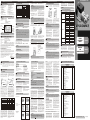
1
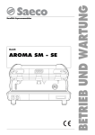
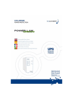
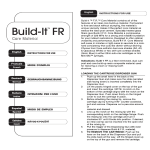
A
INHALTSVERZEICHNIS
Inhaltsverzeichnis
Angaben zu Maschine und Hersteller
Quasimaschinen-Einbauerklärung
Maschinenbeschreibung
Technische Daten
E1 Leistungen
E2 Elektrische Daten
F Betriebsbedingungen
F1 Umgebungsbedingungen
F2 Stromversorgung
F3 Arbeitszyklus
F4 Zulässige / unzulässige Fluide
G Beförderung und Transport
H Installation
H1 Entsorgung der Verpackung
E2
A
B
C
D
E
B
DEUTSCH (Übersetzt aus dem Italienischen)
H2
H3
H4
H5
I
L
M
N
O
P
Q
R
S
Vorkontrollen
Mechanischer Einbau
Hydraulikanschluß
Anmerkungen zu Förder- und
Ansaugleitungen
H6 Elektroanschlüsse
Erster Start
Täglicher Einsatz
Probleme und deren Behebung
Wartung
Geräuschentwicklung
Entsorgung von verseuchtem Material
Raumbedarf und Gewicht
Übersichtsbildtafeln und Ersatzteile
Konfiguration Förderleistung und Saugleistung
HERSTELLER:
Modèles disponibles:
• VISCOMAT 350/2 DREIPHASIG 400V/50HZ
• VISCOMAT 200/2 DREIPHASIG 400V/50HZ
PIUSI SPA
VIA PACINOTTI - Z.I. RANGAVINO
46029 SUZZARA (MN)
PRODUKTCODE
MODELL
TECHNISCHE
MERKMALE
BEDIENUNGSANLEITUNG
ACHTUNG
Vergewissern Sie sich stets, daß die Revision der vorliegenden Bedienungsanleitung mit der
auf dem Typenschild angegebenen Revision übereinstimmt.
QUASIMASCHINEN-EINBAUERKLÄRUNG
Die unterzeichnete Firma: PIUSI S.p.A - Via Pacinotti c.m. - z.i.Rangavino
46029 Suzzara (Mantua) - Italien
ERKLÄRT auf ihre eigene Verantwortung, dass die Quasimaschine:
Bezeichnung:
Modell:
Maschinennummer:
Baujahr:
Pumpe zum Ümfüllen von Schmierölen
VISCOMAT GEAR
siehe Losnummer auf dem am Produkt angebrachten CE
Typenschild
siehe Baujahr auf dem am Produkt angebrachten CE Typenschild
den Gesetzesbestimmungen entspricht, die folgende Richtlinien umsetzen:
- Maschinenrichtlinie 2006/42/EG
- Niederspannungsrichtlinie 2006/95/EG
- Richtlinie über die elektromagnetische Verträglichkeit 2004/108/EG
Es wurden die wesentlichen Sicherheitsanforderungen angewandt und eingehalten, die in Anlage I
der Maschinenrichtlinie angeführt sind, die für das Produkt anwendbar und nachstehend
aufgelistet sind: 1.1.3 - 1.1.5 - 1.3.1 - 1.3.2 - 1.3.3 - 1.3.4 - 1.3.8 - 1.4.1 - 1.4.2.1 - 1.5.1 - 1.5.2 - 1.5.4 1.5.5 - 1.5.8 - 1.5.11 - 1.6.1 - 1.6.3 - 1.6.4 - 1.7.1 - 1.7.2 - 1.7.3 - 1.7.4.
Die Dokumentation steht der zuständigen Behörde auf begründetes Verlangen bei der Firma Piusi
S.p.A. oder Beantragung unter der E-Mail Adresse: [email protected] zur Verfügung.
Die zur Erstellung des technischen Heftes und Abfassung der
Erklärung autorisierte Person ist Herr Otto Varini in seiner
Eigenschaft als gesetzlicher Vertreter.
Suzzara, 29/12/20109
E
Strom Spannung Frequenz Nenn
(V)
(Hz)
(Watt)
230
50
550
4
1450
VISCOMAT 200/2 EINPHASIG 230V/60HZ
AC
230
60
550
4.7
1700
VISCOMAT 200/2 DREIPHASIG 400V/50HZ
AC
400
50
550
1.5
1450
VISCOMAT 350/2 EINPHASIG 230V/50HZ
AC
230
50
900
6.3
1450
VISCOMAT 350/2 DREIPHASIG 400V/50HZ
AC
400
50
750
2.5
1450
VISCOMAT 230/3 230V/50HZ
AC
230
50
900
6
1400
VISCOMAT 230/3 400V/50HZ
15
400
50
750
2.7
1400
ACHTUNG
Die Leistungsaufnahme der Pumpe hängt vom Betriebspunkt und von der Viskosität des
gepumpten Öls ab.
Die in der Tabelle angegebenen Daten zum SPITZENSTROM beziehen sich auf Pumpen, die
im Punkt maximaler Verdichtung P max mit Ölen läuft, deren Viskosität etwa bei 500 cSt liegt.
der gesetzliche Vertreter
Selbstansaugende Elektrozahnradkapselpumpe mit Innenprofil und
By-pass-Ventil.
Einphasen- oder Drehstromasynchronmotor, 2-polig oder 4-polig, geschlossene
Bauweise (Schutzklasse IP55 gemäß Richtlinie EN 60034-5-86) eigenbelüftet,
direkt am Pumpengehäuse angeflanscht.
TECHNISCHE DATEN
wird, den die Pumpe überwinden muß.
Im Diagramm "A" wird eine für alle
Pumpenmodelle der Familie VISCOMAT
typische Kurve Saugleistung/Gegendruck
illustriert.
Die Verwendung des einen oder des anderen Ansaugstutzens hat keine Auswirkungen auf
die Pumpenleistungen, die praktisch in beiden Fällen gleich bleiben.
Trotzdem ist bei der Entscheidung über die Installation zu beachten, daß sie auf eine
möglichst kurze und gerade Saugleitung zwischen dem Behälter und der Pumpe gezielt sein
muß, um die Saugbedingungen zu optimieren.
Pumpenfüllung zum Ausscheiden der eventuell
in der Installation vorhandenen Luft dient.
Die Vorrichtung verfügt über einen 1,5 m
langen Schlauch, der in den Ansaugtank
einzuführen ist.
ZUM TANK
Falls die Installation mit einem Grundventil
versehen ist, kann man die Füllvorrichtung
nach Beendigung der Startphase schließen
(siehe Abschnitt "I"). Will man hingegen das
Entlüftungsventil immer offen lassen, ist auch
zu berücksichtigen, daß ein Anteil des
Öldurchflusses gleich 0.5 ÷ 1 l/min im
Behälter umläuft (siehe Abschnitt "I").
ACHTUNG
STROMVERSORGUNG
Die höchsten, akzeptablen Abweichungen bei
den elektrischen Parametern sind folgende:
Spannung:
Frequenz:
+/- 5% vom Nennwert
+/- 2% vom Nennwert
Sich vergewissern, daß der Entlüftungsschlauch nicht in das Öl des Entnahmebehälters
getaucht wird, weil in diesem Fall die Füllvorrichtung nicht funktionieren könnte.
INSTALLATION EINES DRUCKWÄCHTERS
automatischen Betriebs/Stoppens des Pumpenelektromotors vorgesehen, muß dieser stromab
der Füllvorrichtung angebracht werden.
Ist ein Druckwächter zur Steuerung des
FÜLLVORRICHTUNG
RÜCKSCHLAGVENTIL
(falls am Pressostat nicht integriert)
DRUCKWÄCHTERS
ARBEITSZYKLUS
Die Motoren sind für Dauerbetrieb ausgelegt.
Unter normalen Betriebsbedingungen können sie im Dauerbetrieb ohne Einschränkungen arbeiten.
Ein Betrieb unter By-pass-Bedingungen ist nur kurzzeitig (höchstens 2-3 Minuten) zulässig.
Sollte bei einer besonderen Anwendung die Gefahr bestehen, daß für längere Zeit im By-pass
gearbeitet wird, ist es unbedingt erforderlich, dafür zu sorgen, daß die bypassierte
Saugleistung nicht im Inneren der Pumpe umgewälzt wird, sondern wieder in den
Ansaugbehälter zurückgeführt wird.
ZULÄSSIGE / UNZULÄSSIGE FLUIDE
ZULÄSSIG SIND:
• ÖL mit einer VISKOSITÄT von 50 bis 2000 cSt (bei Betriebstemperatur)
UNZULÄSSIG SIND:
• BENZIN
• ENTZÜNDLICHE FLÜSSIGKEITEN mit PM < 55°C
• WASSER
• LEBENSMITTELFLÜSSIGKEITEN
• KORROSIVE, CHEMISCHE PRODUKTE
H
BESTEHENDE GEFAHR:
• BRAND - EXPLOSION
• BRAND - EXPLOSION
• ANROSTEN DER PUMPE
• VERSEUCHUNG DERSELBEN
• KORROSION DER PUMPE
PERSONENSCHADEN
• BRAND - EXPLOSION
SCHÄDEN AN DEN DICHTUNGEN
BEFÖRDERUNG UND TRANSPORT
Vor dem Versand werden die Pumpen
sorgfältig verpackt.
Überprüfen Sie die Verpackung bei Erhalt und
lagern Sie die Pumpe an einem trockenen Ort.
ACHTUNG
Verfügt die Füllvorrichtung nicht über ein Rückschlagventil, muß ein solches zwischen der
Füllvorrichtung und dem Druckwächter angebracht werden.
H4
Saugleistun
[Q] l/min
Saugleistung
[Q] l/min
Diagramm “A”
• Vergewissern Sie sich, daß sich in den
Rohrleitungen und im Ansaugtank keinerlei
Schlacken oder Rückstände des
Gewindeschnitts befinden, die die Pumpe
und deren Zubehör beschädigen könnten.
• Setzen Sie immer einen Filter mit Metallsieb
am Ansaugrohr ein.
• Bevor Sie die Förderleitung anschließen,
füllen Sie das Pumpengehäuse teilweise
mit Öl, um zu vermeiden, daß die Pumpe
beim Füllen nicht trocken läuft.
• Beim Anschließen der Pumpenmodelle
mit BSP-Gewinde (Kegelgasanschluß)
keinesfalls Verbindungsstücke mit
kegeligem Gewinde verwenden. Zu
starkes Anziehen dieser Verbindungsstücke
könnte zu Schäden an den Stutzen der
Pumpe führen.
Die empfohlenen MINDEST-Merkmale für die Leitungen sind folgende:
ANSAUGLEITUNG
- Durchmesser:
- Nenndruck:
1"
2 mal der Druck P Bypass
(siehe Tabelle im Abschnitt E1 - LEISTUNGEN)
- für Unterdruckbetrieb geeignet
FÖRDERLEITUNG
- Durchmesser:
- Nenndruck:
1/2"
2 mal der Druck P Bypass
(siehe Tabelle im Abschnitt E1 - LEISTUNGEN)
INSTALLATION
Gegendruck [P] bar
Punkt "1" ist der Betriebspunkt, in dem fast
kein Gegendruck vorhanden ist und in dem
die Pumpe die maximale Saugleistung (Q
max) erbringt.
Im Punkt "2" besteht hingegen der maximale
Gegendruck (P max), in diesem Punkt
erbringt die Pumpe die geringste
Saugleistung (Q min).
Sobald der Gegendruck den Wert P max
übersteigt, wird der By-pass selbst dank
seiner speziellen Konformation plötzlich
geöffnet, was zu einer ebenso umgehenden
Reduzierung der Saugleistung führt.
Bei einer Ansaugleistung gleich null (Punkt
PUMPENMODELL
umweltbelastend ist.
Hinsichtlich der Entsorgung beachten Sie
die lokalen Verordnungen.
Gegendruck [P] bar
"3") wird die gesamte Saugleistung der
Pumpe in By-pass umgewälzt, und der
Druck der Förderleitung erreicht den Wert P
By-pass.
Die Pumpen VISCOMAT sind daher in der
Lage, mit einem beliebigen Gegendruck
zwischen Null und P max zu laufen und
dabei eine nur gering in Abhängigkeit vom
Gegendruck variierende Leistung
erbringen, die zwischen den Werten Q
max und Q min Iiegt.
Die Werte für Q min, Q max, P max, P
by-pass, werden für jedes einzelne Modell
in der untenstehenden Tabelle angegeben:
Q max
Q min
(Liter/min) (Liter/min)
P max
(bar)
P by-pass
(bar)
VISCOMAT 200/2 EINPHASIG 230V/50HZ
12
9
11
15
VISCOMAT 200/2 EINPHASIG 230V/60HZ
12
9
11
15
VISCOMAT 200/2 DREIPHASIG 400V/50HZ
12
9
11
15
VISCOMAT 350/2 EINPHASIG 230V/50HZ
12
9
25
30
VISCOMAT 350/2 DREIPHASIG 400V/50HZ
12
9
25
30
VISCOMAT 230/3 230V/50HZ
15
13.5
16
19
VISCOMAT 230/3 400V/50HZ
15
13.5
16
19
Die Pumpen VISCOMAT sind in der Lage,
Ölsorten mit sehr unterschiedlicher Viskosität zu
pumpen, ohne daß der By-pass deswegen
verstellt werden müßte. Die Viskosität muß
jedoch innerhalb der Grenzen liegen, die in den
TECHNISCHEN DATEN angegeben sind. Die
typische Kurve Ansaugleistung/Gegendruck,
wie im Diagramm "A" veranschaulicht, bezieht
sich auf den Betrieb mit Öl, daß eine Viskosität
von etwa 110cSt (die beispielsweise bei dem
Öl SAE W80 bei einer Temperatur von 45°C
auftritt) aufweist.
ENTSORGUNG DER VERPACKUNG
Für das Verpackungsmaterial sind keine
besonderen Vorkehrungen zur Entsorgung
zu treffen, da es weder gefährlich noch
Diagramm “B”
Sobald die Viskosität des Öls sich ändert,
verändern sich die Leistungen der Pumpe in
dem Maße, wie der Gegendruck, unter dem
die Pumpe arbeitet, zunimmt.
Das Diagramm "B" zeigt, wie sich die typische
Kurve im Falle der höchsten und der niedrigsten
Viskosität (jeweils bei 50 cSt und bei 500 cSt)
verändert. Wie man sieht, verändert sich die
Ansaugleistung Q min beim höchsten
Arbeitsgegendruck (Pmax) um 10% bis 15%
gegenüber dem Wert, der bei einer Viskosität
von 110 cSt auftritt.
H2
H3
Die Verwendung von Rohren bzw. Bauteilen, die nicht für die Verwendung mit Öl geeignet
sind und deren Nenndruck nicht angemessen ist, können Personen- und Sachschäden
sowie Umweltbelastung hervorrufen.
Auch das Lockern von Verbindungen (Gewindeverbindungen, Flanschverbindungen,
Dichtungen) kann zu Personen- und Sachschäden sowie Umweltbelastung führen.
Nach dem Einbau und im Anschluß daran in regelmäßigen und angemessenen Abständen
sind alle Verbindungen zu überprüfen.
VORKONTROLLEN
• Vergewissern Sie sich, daß die Maschine
beim Transport oder bei der Lagerung
nicht beschädigt wurde.
• Reinigen Sie die Ansaug- und
Förderstutzen und entfernen Sie
möglichen Staub oder Verpackungsreste.
• Vergewissern Sie sich, daß die Motorwelle frei dreht.
• Vergewissern Sie sich, daß die elektrischen
D a t e n d e n a u f d e m Ty p e n s c h i l d
angegebenen Daten entsprechen.
Die Pumpen der Serie Viscomat können auf folgende zwei Weisen installiert werden:
H5
ANMERKUNGEN ZU FÖRDER- UND ANSAUGLEITUNGEN
FÖRDERUNG
Bei der Wahl des zu verwendenden Pumpenmodells müssen die Viskosität des zu pumpenden
Öls und die Merkmale der Anlage auf der
Förderseite der Pumpe berücksichtigt werden.
Die Kombination aus Viskosität des Öls und
Merkmalen der Anlage kann in der Tat einen
Gegendruck erzeugen, der über dem
vorgesehenen Höchstdruck (gleich P max)
liegt, der ein (teilweises) Öffnen des By-pass
ANSAUGUNG
b) An der Wand,
mit nach oben schauendem
Pumpenkörper:
c) An der Wand,
mit seitlich liegendem
Pumpenkörper:
werden, vermieden werden.
• Sollte die Anlagen ganz aus metallenen
Rohrleitungen oder in jedem Fall aus Leitungen
mit hoher Steifigkeit bestehen, sollte die
Möglichkeit in Betracht gezogen werden,
Die Einphasenmotoren sind mit zweipoligem
Schalter und Kondensatoren ausgestattet, die
im Inneren des Klemmbretts verkabelt und angeschIossen sind (siehe Schaltplan). Die Motoren
sind außerdem mit einem Überhitzungsschutz
mit selbsttätiger Rückstellung ausgerüstet. Die
Merkmale des Kondensators sind für jedes Modell
auf dem Typenschild der Pumpe angegeben.
Der Schalter hat Ein-/Ausschaltfunktion für
die Pumpe und kann keinesfalls den Hauptschalter ersetzen, den die anwendbaren
Richtlinien vorsehen.
ACHTUNG
PROBLEME UND DEREN BEHEBUNG
DER MOTOR LÄUFT
NICHT
Die Pumpen der Serie VISCOMAT zeichnen sich
durch eine ausgezeichnete Ansaugleistung aus.
Die typische Kurve Saugleistung/Gegendruck
bleibt bis in hohe Unterdruckwerte hinein bei
der Ansaugung der Pumpe unverändert.
Bei Ölsorten mit Viskosität bis höchstens 100
cSt kann der Unterdruck an der Ansaugung
Werte zwischen 0,7 - 0,8 bar erreichen, ohne
den einwandfreien Betrieb der Pumpe zu
beeinträchtigen.
Oberhalb besagter Unterdruckwerte beginnt
die Hohlsogbildung, die sich durch eine
stärkere Geräuschentwicklung während des
Betriebs bemerkbar macht. Diese
Hohlsogbildung kann mit der Zeit zur
Beschädigung der Pumpe und darüber hinaus
zu einem Leistungsabfall führen.
Je mehr die Viskosität zunimmt, um so geringer
wird der Unterdruck, bei dem Hohlsogbildung
der Pumpe mit daraus folgender, merklicher
Reduzierung der Saugleistung zur Folge hat.
In diesem Fall ist es erforderlich, die
Widerstände der Anlage durch Verwendung
kürzerer Rohre bzw. von Rohren mit größerem
Durchmesser zu reduzieren, damit der
einwandfreie Betrieb der Pumpe bei gleicher
Viskosität des gepumpten Öls gewährleistet ist.
Da es im Gegenzug nicht möglich ist, die
Anlage zu verändern, muß ein Pumpenmodell
mit höherem P max gewählt werden.
auftreten kann.
Bei Ölsorten mit Viskosität von etwa 500 cSt
darf der Unterdruck an der Ansaugung Werte
zwischen 0,3 - 0,5 bar nicht überschreiten, um
Hohlsogbildung zu vermeiden.
Die oben angegebenen Richtwerte beziehen
sich auf die Ansaugung von Ölsorten, die im
wesentlichen keine Luft aufweisen.
Falls das gepumpte Öl in emulgierter Form
mit Luft vorliegt, kann die Hohlsogbildung
bereits bei geringerem Unterdruck auftreten.
In jedem Fall ist es im Rahmen der obigen
Ausführungen wichtig, an der Ansaugung
niedrigen Unterdruck zu gewährleisten
(kurze Leitungen und mit größerem
Durchmesser als der Durchmesser des
Ansaugstutzens der Pumpe; geringe Anzahl
von Kurven; Filter mit großem Querschnitt, die
stets sauber gehalten werden).
ACHTUNG
In der Anlagentechnik sollte es selbstverständlich sein, ober- und unterhalb der Pumpe
Unterdruckmesser und Manometer einzubauen, um überprüfen zu können, ob die
Betriebsbedingungen im Rahmen der vorgesehenen Bedingungen liegen.
Es wird empfohlen, ein Grundventil einzubauen, damit sich die Ansaugleitung beim
Abstellen der Pumpe nicht entleert.
DER MOTOR LÄUFT
BEIM STARTEN
LANGSAM
Im Lieferumfang der Pumpen sind keine elektrischen Sicherheitsvorrichtungen wie
Schmelzdrahtsicherungen, Motorschutz, Systeme gegen unbeabsichtigtes Starten nach
Stromausfall oder andere enthalten.
Der Monteur, der die elektrischen Anschlüsse ausführt, ist für die Einhaltung der
anwendbaren Richtlinien verantwortlich.
sich unter Bezugnahme auf Abschnitt R RAUMBEDARF UND GEWICHT, daß die
Drehrichtung korrekt ist.
• Alle Motoren sind mit Erdungsklemme
versehen, die an die Erdung des Netzes
angeschlossen werden muß.
• Schließen Sie stets den Deckel des
Klemmbretts, bevor Sie die Stromversorgung
wieder einschalten, nachdem Sie die Unversehrtheit der Dichtungen überprüft haben,
die die Schutzklasse IP55 gewährleisten.
ERSTER START
Die Pumpen der Serie VISCOMAT sind selbstansaugend und daher in der Lage, Öl aus dem
Tank auch dann anzusaugen, wenn die Ansaugleitung beim Starten leer ist. Die Saughöhe
(Abstand zwischen Ölspiegel im Tank und Ansaugstutzen) darf nicht mehr als 2,5 Meter betragen.
ACHTUNG
Versorgen der Pumpe mit Flüssigkeit. Vor dem Anlassen der Pumpe anhand der Ein- und
Auslaßstutzen das Innere des Pumpenkörpers mit Öl benetzen.
Wurde die Pumpe bereits installiert, zum Verrichten dieses Vorgangs den Gewindeverschluß
des nicht verwendeten Einlaßstutzens (IN1 oder IN2) abschrauben, die innere Kammer mit Öl
füllen und den Verschluß wieder anschrauben. Auf den O-Ring zur Abdichtung achten.
Bei der Füllphase muß die Pumpe die anfänglich in der Leitung enthaltene Luft ausstoßen.
Deshalb muß man das Ventil der Füllvorrichtung (Pos. 32 auf der Explosionszeichnung) gegen
Uhrzeigersinn drehen, so daß die vorhandene Luft ausgeschieden wird.
Wenn sich der Schlauch mit Öl gefüllt hat, ist die Luftbeseitigungsphase beendet.
Sollte sich diese Phase über Gebühr
hinausziehen, schalten Sie die Pumpe ab
und vergewissern sich:
• daß die Pumpe nicht völlig "trocken" läuft;
• daß das Eindringen von Luft in die
Ansaugleitung nicht möglich ist und die
Leitung selbst sich korrekt in der
anzusaugenden Flüssigkeit befindet;
• daß der eventuelle Filter in der
Ansaugung nicht verstopft ist;
• daß die Saughöhe 2,5 Meter nicht überschreitet;
• daß die Luft aus der Förderleitung leicht
entweichen kann.
Sobald der Füllvorgang abgeschlossen ist und die
Abgabepistole eventuell wieder montiert wurde,
vergewissern Sie sich, daß die Pumpe im
gesamten, vorgesehenen Bereich arbeitet.
L
Kontrollieren Sie dazu möglichst folgendes:
1) Der Leistungsbedarf des Motors muß
unter maximalen Leistungsbedingungen
innerhalb der auf dem Typenschild
angegebenen Werte liegen.
2) Der Unterdruck an der Ansaugung darf die in
Abschnitt H5 - ANMERKUNGEN ZU FÖRDERUND ANSAUGLEITUNGEN angegebenen
Grenzwerte nicht überschreiten.
3) Der Gegendruck auf der Förderseite darf die
in Abschnitt H5 - ANMERKUNGEN ZU
FÖRDER- UND ANSAUGLEITUNGEN angegebenen Grenzwerte nicht überschreiten.
Zwecks korrekter und umfassender
Überwachung der Punkte 2) und 3) sollten
oberhalb undunterhalb der Pumpe Unterdruckmesser und Manometer eingebaut werden.
TÄGLICHER EINSATZ
Vor dem täglichen Einsatz der Pumpen VISCOMAT ist keine besondere Vorkehrung zu treffen.
HANDBETRIEB
• Vor dem Starten der Pumpe vergewissern
Sie sich, daß das eventuelle, abschließende Sperrorgan (Abgabepistole oder
Leitungsventil) geschlossen ist.
• Falls auf der Förderseite keine Sperre
eingebaut ist (freie Förderung), vergewissern
Sie sich, daß die Förderleitung richtig
positioniert und in einer entsprechenden
Aufnahme am Fördertank befestigt ist.
• Den Betriebsschalter, der an einigen
(einphasigen) Pumpenmodellen vorhanden
ist, oder den Ein-/Aus-Schalter an der
Versorgungsleitung betätigen.
• Vergewissern Sie sich, daß im Tank eine
zur Abgabe ausreichende Menge Öl
vorhanden ist (Trockenlaufen kann die
Pumpe beschädigen).
ACHTUNG
• Das Förderventil öffnen oder die Abgabepistole betätigen und sie dabei gut festhalten.
Behebung
Keine Stromversorgung
Elektrische Anschlüsse und
Sicherheitssysteme kontrollieren
Probleme am Motor
Rotierende Organe auf mögliche
Schäden oder Verstopfungen hin
überprüfen
Warten, bis der Motor abgekühlt ist.
Den erneuten Start überprüfen und die
Ursache für die Übertemperatur suchen
Kundendienst anrufen
Niedrige Versorgungsspannung
Die Spannung wieder in die
vorgesehenen Grenzen bringen
Rotor blockiert
Niedriger Stand im Ansaugtank
Die Öltemperatur überprüfen und
das Öl eventuell anheizen, um die
übermäßige Viskosität zu reduzieren
Den Tank füllen
Grundventil blockiert
Das Ventil reinigen bzw. auswechseln
Filter verstopft
Überhöhter Ladeverlust im
Förderkreislauf (Betrieb mit
geöffnetem By-pass)
Den Filter reinigen
Die Pumpe gegenüber dem Ölstand
im Tank niedriger setzen oder den
Querschnitt der Leitungen erhöhen
Kürzere Leitungen oder Leitungen
mit größerem Durchmesser
verwenden
By-pass-Ventil blockiert
Das Ventil ausbauen, reinigen
bzw. auswechseln
Eindringen von Luft in die Pumpe
oder in die Ansaugleitung
Überprüfen, ob die Verbindungen
dicht sind
Verengung am Ansaugrohr
Ein für den Betrieb mit Unterdruck
angemessenes Rohr verwenden
Niedrige Drehzahl
Die Spannung an der Pumpe kontrollieren; die Spannung regulieren bzw. Kabel
mit größerem Querschnitt erwenden
Die Ansaugleitung liegt am
Boden des Tanks
Die Leitung anheben
Übermäßige Viskosität des Öls
Die Öltemperatur überprüfen und
das Öl eventuell anheizen, um die
übermäßige Viskosität zu reduzieren
Hohlsogbildung
Den Unterdruck an der Ansaugung
reduzieren (siehe Abschnitt H5)
Unregelmäßiger By-passBetrieb
Abgeben, bis die im By-pass-System
vorhandene Luft entwichen ist
Luft im Öl
Warten, bis sich das Öl im Tank
gesetzt hat
Beschädigung der mechanischen Dichtung
Die mechanische Dichtung
überprüfen und ggf. auswechseln
Überhöhte Viskosität des Öls
Übermäßiger Unterdruck in
der Ansaugung
GERINGE ODER KEINE
SAUGLEISTUNG
HOHE GERÄUSCHENTWICKLUNG DER
PUMPE
LECKAGE AM
PUMPEGEHÄUSE
N
GERÄUSCHENTWICKLUNG
Unter normalen Betriebsbedingungen überschreitet die Geräuschentwicklung bei allen
P
ENGLISH
BEDIENUNGSUND
WARTUNGSANLEITUNG
DEUTSCH
Modellen den Wert von 70 dB "A" in 1 Meter
Entfernung zur Elektropumpe nicht.
ENTSORGUNG VON VERSEUCHTEM MATERIAL
Bei Wartung oder Ausschlachtung der
Maschine umweltbelastende Teile umweltgerecht in den entsprechenden Deponien
Q
USE AND
MAINTENANCE
MANUAL
WARTUNG
Die Pumpen der Serie Viscomat sind für eine minimale Wartung konzipiert und gebaut.
• Einmal wöchentlich kontrollieren, ob die
mutzungen entfernen.
Verbindungen der Rohrleitungen nicht locker
• Einmal monatlich die Filter oberhalb der
sind, um eventuelle Leckagen zu vermeiden.
Pumpe kontrollieren und sauber halten.
• Einmal monatlich das Pumpengehäuse
• Einmal monatlich die Stromversorgungskontrollieren und eventuelle Verschkabel auf Ihren guten Zustand hin kontrollieren.
O
Wurde kein Grundventil installiert, empfiehlt es sich, das Entlüftungsventil immer offen zu
lassen, damit die Vorrichtung bei der nächsten Anlassung schon bereitgestellt ist, um die im
Saugschlauch enthaltene Luft auszustoßen. Bitte berücksichtigen Sie, daß während des
Betriebs ein kleiner Anteil des Öldurchflusses im Behälter umläuft.
Ist hingegen ein Grundventil vorhanden, empfiehlt es sich, das Entlüftungsventil zu schließen,
indem man es im Uhrzeigersinn dreht, so daß es keine unnötigen Ölumläufe im Behälter gibt.
Dichtet das Grundventil nicht perfekt ab, könnte sich der Saugschlauch entleeren und folglich
muß der o. g. Luftbeseitigungsvorgang wiederholt werden.
Mögliche Ursache
Der Motorüberhitzungsschutz
greift ein
ACHTUNG
• Beim Einbaus und bei Wartungsarbeiten
vergewissern Sie sich, daß die
Stromversorgungsleitungen nicht unter
Spannung stehen.
• Verwenden Sie Kabel mit Mindestquerschnitten und Nennspannungen und achten Sie
darauf, daß auch die Art der Verlegung den
im Abschnitt E2 - ELEKTRISCHE DATEN
angegebenen Merkmalen und der
Installationsumgebung entspricht.
• Bei Drehstrommotoren vergewissern Sie
einen leistungsfähigen Akku einzubauen, um
zu vermeiden, daß auch Leckagen geringen
Ausmaßes (beispielsweise am Grundventil) einen Druckabfall verursachen, der zum
automatischen Einschalten der Pumpe führt.
Mangelnde Beachtung obiger Angaben kann zu Schäden an der Pumpe führen.
Problem
ZUM
MOTOR
Bulletin M0040B EN/DE - Rev. 1
DEUTSCH (Übersetzt aus dem Italienischen)
M
ZUM MOTOR
Starten Sie die Pumpe keinesfalls durch bloßes Einstecken des Steckers in die Steckdose!
MECHANISCHER EINBAU
a) Mit waagrechter Achse:
EINPHASIG
Das Füllen kann, je nach Anlage, einige Sekunden bis wenige Minuten in Anspruch
nehmen.
HYDRAULIKANSCHLUSS
ACHTUNG
H1
öffnen Sie den Deckel am Klemmbrett,
entfernen Sie besagtes Kabel und schließen
Sie die Leitung nach folgendem Schaltplan
an.
ACHTUNG
ACHTUNG
Aufgrund des geringen Gewichts und der
geringen Abmessungen der Pumpen (siehe
Platzbedarf) ist der Einsatz von Hebezeugen
zum Befördern der Pumpen nicht erforderlich.
DREIPHASIG
WS
I
Die Stromversorgung über Leitungen, deren Werte sich außerhalb der angegebenen
Grenzen befinden, kann zu Schäden an den elektrischen Bauteilen führen.
G
Alle Motoren sind mit einem kurzen Kabel
ausgestattet, das für Produktionstests
verwendet wird.
Zum Anschließen des Motors an die Leitung
Beachten Sie folgende (nicht erschöpfende) Angaben zwecks korrekter Elektroinstallation:
ACHTUNG
F3
ELEKTRISCHE ANSCHLÜSSE
Bei der Lieferung ist der Stutzen "IN2" durch einen
Gewindeverschluß mit "O-Ring" verschlossen und
die Pumpe ist zum Gebrauch unter Verwendung
des Stutzens "IN1" vorbereitet. Will man den
Stutzen "IN2" verwenden, muß man den
Gewindeverschluß und den O-Ring des Stutzens
"IN2" entfernen und am Stutzen "IN1" anbringen.
Zur leichteren Installation hat der Pumpenkörper zwei Ansaugstutzen:
- Der Stutzen "IN1" ist mit dem Förderstutzen
"OUT" ausgerichtet.
- Der Stutzen "IN2" liegt parallel zur
RELATIVE LUFTFEUCHTIGKEIT:
max. 90%
Die angegebenen Grenztemperaturen beziehen sich auf die Bauteile der Pumpe und müssen
eingehalten werden, um mögliche Schäden oder Störungen zu vermeiden. Es versteht sich jedoch,
daß der effektive Betriebstemperaturbereich für ein bestimmtes Öl auch von der Veränderlichkeit
der Viskosität des Öls selbst in bezug auf die Temperatur abhängt. Insbesondere gilt folgendes:
• Die zulässigen Mindesttemperaturen (-10°C) können die Viskosität einiger Ölsorten weit über
die zulässigen Höchsttemperaturen hinaus ansteigen lassen. Dies kann es dann mit sich
bringen, daß der beim Starten der Pumpe erforderliche Anlaufdrehmoment exzessiv ist, was
wiederum zu Überströmen und Beschädigung der Pumpe führen kann.
• Die zulässigen Höchsttemperaturen (+60°C) können wiederum die Viskosität einiger Ölsorten weit
unter die zulässigen Mindesttemperaturen sinken lassen. Dies kann zu einem Abfall der Leistung
mit evidenter Reduzierung der Saugleistung in dem Maße führen, wie der Gegendruck ansteigt.
Je nach Pumpenmodell hat die Stromversorgung über eine Drehstrom- oder eine Einphasenleitung mit Wechselstrom zu erfolgen,
deren Nennwerte in der Tabelle im Abschnitt
E2 - ELEKTRISCHE DATEN angegeben sind.
H6
Motorachse und folglich 90° im Vergleich
zum Förderstutzen "OUT".
Die Pumpen der Serie Viscomat sind mit einer,
am Förderstutzen OUT angebrachten
Füllvorrichtung ausgerüstet, die bei der
UMGEBUNGSBEDINGUNGEN
LEISTUNGEN
Die Leistungen der einzelnen
Pumpenmodelle aus der Familie VISCOMAT
können mit Hilfe von Kurven veranschaulicht
werden, in denen das Verhältnis von
Saugleistung und Gegendruck angegeben
Die Pumpe anhand Schrauben angemessenen
Durchmessers an den vorhandenen
Befestigungslöchern befestigen (siehe
Zeichnung "Außenmaße und Gewichte)".
ACHTUNG
F4
MASCHINENBESCHREIBUNG
ACHTUNG
Es wird davon abgeraten, die Pumpe mit senkrechter Achse und nach unten schauendem
Pumpenkörper anzubringen.
Sollte dies unvermeidbar sein, ist die Installation eines Grundventils erforderlich und beim
ersten Anlassen muß man den Saugschlauch mit Öl füllen.
FÜLLVORRICHTUNG
BETRIEBSBEDINGUNGEN
TEMPERATUR:
min. -10°C / max. +60°C
Anlage auch nach der ersten Füllung sofort
und leicht wieder zu verwenden.
DEUTSCH (Übersetzt aus dem Italienischen)
ACHTUNG
• LÖSUNGSMITTEL
E1
Spitzen Nenn
(Amp) (U/Min)
AC
F2
die zum Einbau in eine Maschine (oder Zusammensein mit anderen Maschinen) bestimmt ist, um
eine Maschine zu bilden, für die die Maschinenrichtlinie 2006/42/EG gilt, so lange nicht in Betrieb
gesetzt werden darf, bis die Maschine, in die sie eingebaut wird, als konform mit den
Bestimmungen der Richtlinie 2006/42/EG erklärt wird;
MOTOR:
LEISTUNG STROM DREHZAHL
VISCOMAT 200/2 EINPHASIG 230V/50HZ
F1
BAUJAHR
PUMPE:
STROMVERSORGUNG
PUMPENMODELL
F
TYPENSCHILD (BEISPIEL MIT ANGABE DER EINZELNEN FELDER):
D
Es wird nahegelegt, stets ein Rückschlagventil anzubringen, das es ermöglicht, die
ELEKTRISCHE DATEN
ANGABEN ZU MASCHINE UND HERSTELLER
Erhältliche Modelle:
• VISCOMAT 200/2 EINPHASIG 230V/50HZ
• VISCOMAT 200/2 EINPHASIG 230V/60HZ
• VISCOMAT 350/2 EINPHASIG 230V/50HZ
C
DEUTSCH (Übersetzt aus dem Italienischen)
KONDENSATOR
DEUTSCH (Übersetzt aus dem Italienischen)
entsorgen.
Beachten Sie die lokalen Vorschriften zur
korrekten Entsorgung.
ÜBERSICHTSBILDTAFELN UND ERSATZTEILE
VISCOMAT 200/2
Position
1
2
3
4
5
6
7
8
9
10
11
12
13
14
15
16
17
18
20
21
22
23
24
25
26
27
28
29
30
31
32
Bauteilbezeichnung
SCHRAUBE UNI 9327 M8X50-8.8 ZN
PUMPENKNOPF MIT GEWINDE
DICHTUNG O-RING 3118
VERSCHLUSS G1"X15
DICHTUNG O-RING 3068
DISTANZSTÜCK Ø14
BY-PASS VERSCHLUSS
BY-PASS VENTIL
ZYLINDRISCHE DRUCKSCHRAUBENFEDER
STIFT Ø 5X14
ZUGSTAB M5X145
FLANSCH MEC71, GEDREHT
MOTOR
LAUFRADDECKEL AUS KUNSTSTOFF
FEDERKEIL
LAGER 6203 MIT 2 SCHUTZSCHIRMEN
AUSGLEICHSRING
SCHLAGSCHRAUBE M6X25 DIN 7500/C
PUMPENFLANSCH
DICHTUNG O-RING 123
ORTSFESTE RUTSCHENSEITE Ø14
DREHENDE RUTSCHENSEITE Ø14
DICHTUNG O-RING 117
MESSINGSCHEIBE
KEGELFEDER
SEEGER FÜR SCHAFT
AUSSENROTOR H12
INNENROTOR H12
DICHTUNG O-RING
MUTTER UNI 5588 M5 - 5S ZN
ENTLÜFTUNGSSATZ
Menge
3
1
1
1
1
1
1
1
1
2
4
1
1
1
1
1
1
4
1
1
1
1
1
1
1
1
1
1
1
4
1
ACHTUNG
Aus der Pistole, die über die Pumpe VISCOMAT gespeist wird, tritt das Fluid unter hohem Druck aus.
Richten Sie die Mündung der Pistole keinesfalls auf Teile des Körpers.
• Schließen Sie die Abgabepistole oder das Leitungsventil, um die Abgabe zu unterbrechen.
Die Pumpe begibt sich automatisch in den By-pass-Modus.
ACHTUNG
Der By-pass-Betrieb mit geschlossener Förderleitung ist nur kurzzeitig (höchstens 2-3
Minuten) gestattet. Sobald der Überhitzungsschutz ausgelöst wird, ist die Stromversorgung zu unterbrechen und es muß gewartet werden, bis der Motor abgekühlt ist.
• Abstellen der Pumpe.
AUTOMATIKBETRIEB
Bei besonderen Anwendungen kann es
angebracht sein, das automatische
Ein- und Ausschalten der Pumpe mit Hilfe
eines Pressostats vorzusehen, daß den
Druck in der Förderleitung erfaßt.
Die Betriebslogik stellt sich bei derartigen
Installationen wie folgt dar:
• Die Pumpe steht, die Abgabepistole ist
geschlossen und die Förderleitung steht
unter Druck.
• Die Pistole wird geöffnet, was zu einem
plötzlichen Abfall des Drucks an der
Förderleitung führt.
• Das Pressostat sorgt dafür, daß in dem
Moment, in dem der Druck unter den Wert
"Pm" absinkt, die Pumpe automatisch eingeschaltet wird und die Abgabe erfolgen kann.
• Während der Abgabe arbeitet die Pumpe
mit einem Gegendruck, der von den
Bedingungen in der Förderleitung
abhängig ist und der über oder unter dem
Druck "Pm" liegen kann.
• Sobald die Pistole geschlossen wird,
steigt der Druck rasch wieder an und das
Pressostat sorgt dafür, daß die Pumpe
automatisch abgeschaltet wird, sobald
der Druck den Wert "Pa" übersteigt.
Die Werte "Pa" und "Pm" sind für das verwendete Pressostat typisch und können oftmals
innerhalb eines bestimmten Bereiches reguliert werden..
Für einen einwandfreien und sicheren Betrieb der Pumpe ist es bei derartigen
Anwendungen absolut unerläßlich, daß folgende Punkte geprüft werden:
• Der "Pa" muß angemessen unter dem Bypass-Druck liegen, damit gewährleistet ist,
daß die Pumpe abschaltet, sobald die Pistole
geschlossen wird und vermieden wird, daß die
Pumpe längere Zeit im By-pass-Modus arbeitet.
• Der "Pm" muß um einige Bar unter dem "Pa"
liegen, um der Gefahr eines unerwarteten
Anlaufens der Pumpe bei minimaler
Reduzierung des Drucks vorzubeugen, die nicht
auf das Öffnen der Pistole zurückzuführen ist.
• Das Grundventil muß wirkungsvolles
Abdichten gewährleisten, damit unerwünschte und häufige Ein-/Ausschaltzyklen, die durch dessen Lecken verursacht
VISCOMAT 350/2
Position
1
2
3
4
5
6
7
8
9
10
11
12
13
14
15
16
17
18
19
20
21
22
23
24
25
26
27
28
29
30
32
Bauteilbezeichnung
VERSCHLUSS G1"X15
DICHTUNG O-RING 3118
PUMPENKNOPF MIT GEWINDE
BY-PASS VENTIL
ZYLINDRISCHE DRUCKSCHRAUBENFEDER
DICHTUNG O-RING 3068
DISTANZSTÜCK Ø14
BY-PASS VERSCHLUSS
STIFT Ø5X14
SPANNSTANGE M5X160
FLANSCH MEC80, GEDREHT
SCHLAGSCHRAUBE M6X25 DIN 7500/C
MOTOR
LAUFRADDECKEL AUS KUNSTSTOFF
FEDERKEIL
LAGER 6204 MIT 2 SCHUTZSCHIRMEN
AUSGLEICHSRING
PUMPENFLANSCH
DICHTUNG O-RING 123
ORTSFESTE RUTSCHENSEITE Ø14
DREHENDE RUTSCHENSEITE Ø14
DICHTUNG O-RING 117
MESSINGSCHEIBE
KEGELFEDER
SEEGER FÜR SCHAFT
AUSSENROTOR H12
INNENROTOR H12
DICHTUNG O-RING
SCHRAUBE UNI 9327 M8X50-8.8 ZN
MUTTER UNI 5588 M5 - 5S ZN
ENTLÜFTUNGSSATZ
Menge
1
1
1
1
1
1
1
1
2
4
1
4
1
1
1
1
1
1
1
1
1
1
1
1
1
1
1
1
3
4
1
Bulletin M0040B EN/DE - Rev. 1
Copyright
A
E2
INDEX
A Index
B Identification of Machine and Manufacturer
C Declaration of Incorporation of
partly-completed Machinery
D Machine Description
E Technical Information
E1 Performance
E2 Electrical Information
F Operating Conditions
F1 Environmental Conditions
F2 Electrical Power
F3 Working Cycle
F4 Fluids Allowed / Fluids Not Allowed
G Moving and Transporting
H Installation
B
ENGLISH (Translated from Italian)
I
L
M
N
O
P
Q
R
S
H1 Disposing of the Packing Materials
H2 Preliminary Inspection
H3 Mechanical Installation
H4 Hydraulic Connection
H5 Suction & Delivery Lines
H6 Electrical Connections
Initial Start-Up
Every Day Use
Problems and Solutions
Maintenance
Noise Level
Disposal of Contaminated Materials
Exploded Diagrams and Spare Parts
Dimensions and Weights
Configuration of Delivery and Suction
ELECTRICAL INFORMATION
ELECTRIC POWER SUPPLY
PUMP MODEL
POWER CURRENT
Current Voltage Frequency Rated
(V)
(Hz)
(Watt)
SPEED
Maximum Rated
(Amp) (g/m)
VISCOMAT 200/2 SINGLE-PHASE 230V/50HZ
AC
230
50
550
4
1450
VISCOMAT 200/2 SINGLE-PHASE 230V/60HZ
AC
230
60
550
4.7
1700
VISCOMAT 200/2 THREE-PHASE 400V/50HZ
AC
400
50
550
1.5
1450
VISCOMAT 350/2 SINGLE-PHASE 230V/50HZ
AC
230
50
900
6.3
1450
VISCOMAT 350/2 THREE-PHASE 400V/50HZ
AC
400
50
750
2.5
1450
VISCOMAT 230/3 230V/50HZ
AC
230
50
900
6
1400
VISCOMAT 230/3 400V/50HZ
15
400
50
750
2.7
1400
IDENTIFICATION OF MACHINE AND MANUFACTURER
Available Models:
Modèles disponibles:
• VISCOMAT 200/2 SINGLE-PHASE 230V/50HZ • VISCOMAT 350/2 THREE-PHASE 400V/50HZ
• VISCOMAT 200/2 SINGLE-PHASE 230V/60HZ • VISCOMAT 200/2 THREE-PHASE 400V/50HZ
• VISCOMAT 350/2 SINGLE-PHASE 230V/50HZ
MANUFACTURER:
PIUSI SPA
VIA PACINOTTI - Z.I. RANGAVINO
46029 SUZZARA (MN)
PRODUCT
CODE
F1
PRODUCTION
YEAR
MODEL
TECHNICAL
DATA
MANUAL
ATTENTION
Always check that the revision level of the present manual agrees with the revision level
indicated on the label.
DECLARATION OF INCORPORATION OF PARTLY-COMPLETED MACHINERY
The undersigned:
ENVIRONMENTAL CONDITIONS
is intended to be incorporated in a machine (or to be with other machines) so as to create a
machine to which applies Machine Directive 2006/42/EC, may not be brought into service before
the machine into which it is to be incorporated has been declared in conformity with the provisions
of the directive 2006/42/EC.
is in conformity with the legal provisions indicated in the directives:
- Machine Directive 2006/42/EC
- Low-Voltage Directive 2006/95/EC
- Electromagnetic Compatibility Directive 2004/108/EC
To which the essential safety requirements have been applied and complied with what indicated
on annex I of the machine directive applicable to the product and shown below: 1.1.3 - 1.1.5 - 1.3.1 1.3.2 - 1.3.3 - 1.3.4 - 1.3.8 - 1.4.1 - 1.4.2.1 - 1.5.1 - 1.5.2 - 1.5.4 - 1.5.5 - 1.5.8 - 1.5.11 - 1.6.1 - 1.6.3 1.6.4 - 1.7.1 - 1.7.2 - 1.7.3 - 1.7.4.
The documentation is at the disposal of the competent authority following motivated request at Piusi
S.p.A. or following request sent to the email address: [email protected]
The person authorised to compile the technical file and draw up
the declaration is Otto Varini as legal representative.
Suzzara, 29/12/2009
The temperature limits indicated are applied to the pump components and must be
respected to avoid possible damage or malfunction.
It is understood, nevertheless, that for a given oil, the real functioning temperature range also
depends on the variability of the viscosity of the oil itself with the temperature. Specifically:
• The minimum temperature allowed (-10°C) could cause the viscosity of some oils to greatly
exceed the maximum allowed, with the consequence that the static torque required during
the starting of the pump would be excessive, risking overload and damage to the pump.
• The maximum temperature allowed (+60°C) could, on the other hand, cause the viscosity
of some oils to drop well below the minimum allowed, causing a degradation in performance
with obvious reductions in flow rate as the back pressure increases.
ELECTRICAL POWER
Depending on the model, the pump must be fed
by three-phase or single-phase alternating current
whose nominal values are those indicated in
the Table of paragraph E2 - ELECTRICAL
INFORMATION. The maximum acceptable
variations from the electrical parameters are:
voltage:
+/- 5% of the nominal value
frequency: +/- 2% of the nominal value
PUMP:
Electric self-priming rotary internal gear pump, equipped with a by-pass valve.
MOTOR:
Asynchronous motor, single-phase or three-phase, 2 or 4 pole, closed type
(Protection class IP55 according to regulation EN 60034-5-86) self-ventilating,
flange-mounted directly to the pump body.
E
TECHNICAL INFORMATION
F3
pressure that the pump must overcome.
Diagram "A" illustrates a flow rate/back
pressure curve typical of all of the pumps in
the VISCOMAT family.
Functioning in by-pass conditions is only allowed for brief periods (2 to 3 minutes
maximum).
Whenever a particular installation carries the risk of functioning in by-pass mode for longer
periods of time, it is necessary that the by-passed flow not be recirculated inside the
pump, but be returned to the suction tank.
FLUIDS ALLOWED / FLUIDS NOT ALLOWED
ALLOWED:
• OIL with a VISCOSITY from 50 to 2000 cSt (at working temperature)
G
Back pressure [P] bar
Point "1" is the point at which the pump is
functioning with practically no back pressure,
in which case the pump supplies the
maximum flow rate (Q max).
Po i n t " 2 " i s t h e f u n c t i o n i n g p o i n t
characterized by the maximum back
pressure (P max) at which the pump supplies
the minimum flow rate (Q min).
When the back pressure exceeds the value
P max, thanks to the special design of the
by-pass, there is a sudden opening of the
by-pass, with a consequent sudden
reduction of the flow rate supplied.
PUMP MODEL
Flow rate [Q] l/min
Flow rate [Q] l/min
H
Diagram “A”
H1
Diagram “B”
RELATED DANGER:
• FIRE - EXPLOSION
• FIRE - EXPLOSION
• OXIDATION OF THE PUMP
• CONTAMINATION OF SAME
• CORROSION OF THE PUMP
INJURY TO PEOPLE
• FIRE - EXPLOSION
DAMAGE TO GASKET SEALS
MOVING AND TRANSPORTING
The pumps are carefully packed before
shipment.
On receipt, check the packing materials and
store in a dry place.
DISPOSING OF THE PACKING MATERIALS
in any way dangerous or polluting.
For disposal, refer to local regulations.
Back pressure [P] bar
H2
At flow rate zero (point "3") the entire flow rate
supplied by the pump is recirculated in the
by-pass, and the pressure in the delivery line
reaches the value of P By-pass.
VISCOMAT pumps can, therefore, function
in the face of any back pressure between
zero and P max, supplying a flow rate
varying little as a function of the back
pressure between the values of Q max and
Q min.
The values for Q min , Q max , P max and
P by-pass are provided for each model of
pump in the Table below:
TO THE TANK
If the system is equipped with a foot valve, the
priming device can be closed once the starting
phase has been completed (see paragraph "I").
If you wish to leave the purge valve always
open, remember that a small quantity of oil recirculates in the tank at a 0.5 ÷ 1 l/min flow rate.
Make sure that the air discharge tube is not immersed in the oil inside the drawing tank.
In this case, the operation of the priming device may be prejudiced.
INSTALLING A PRESSURE SWITCH
automatic on/off piloting of the pump electric
motor, this is to be installed downstream of the
priming device.
PRIMING DEVICE
VNON-RETURN VALVE
(if not integrated into the pressure switch)
PRESSURE SWITCH
Q max.
Q min.
(liters/min) (liters/min)
P max.
(bar)
P by-pass
(bar)
9
11
15
VISCOMAT 200/2 SINGLE-PHASE 230V/60HZ
12
9
11
15
VISCOMAT 200/2 THREE-PHASE 400V/50HZ
12
9
11
15
VISCOMAT 350/2 SINGLE-PHASE 230V/50HZ
12
9
25
30
VISCOMAT 350/2 THREE-PHASE 400V/50HZ
12
9
25
30
VISCOMAT 230/3 230V/50HZ
15
13.5
16
19
VISCOMAT 230/3 400V/50HZ
15
13.5
16
19
the pump's performance will be more
noticeable the greater the back pressure
against which the pump is working.
Diagram "B" illustrates how the characteristic
curve changes in the case of the maximum
and minimum viscosities (respectively equal
to 50 cSt and 500 cSt), showing that, at the
maximum working back pressure (Pmax),
the flow rate Q min suffers a variation of
between 10% and 15% with respect to the
value relative to a viscosity of 110 cSt.
H3
• Make sure that the motor shaft turns
freely.
• Check that the electrical information
corresponds with what is shown on the
label.
MECHANICAL INSTALLATION
The Viscomat series pumps can be installed in the following two ways:
a) On an horizontal base:
THREE PHASE
A.C. LINE
terminal strip cover, remove the above
mentioned cable and connect the line
according to the following chart.
SINGLE PHASE
TO MOTOR
Single-phase motors are supplied with a
bipolar switch and capacitors wired and
installed inside the terminal strip box (see
chart). Motors are likewise equipped with an
automatic reset thermo-protector.
The capacitor characteristics are those
indicated on the pump label.
The switch has the function of starting/stopping
the pump and cannot in any way replace the main
power switch required by the applicable regulations.
I
correct rotation direction by referring to
paragraph R - DIMENSIONS AND
WEIGHTS.
• All motors are equipped with a grounding
terminal that is to be connected to the
ground line of the electrical system.
• Always close the cover of the terminal strip
box before turning on the electric power,
after checking the integrity of the gasket
seals that ensure protection grade IP55.
MOTOR TURNS
SLOWLY WHEN
STARTING
ATTENTION
If the priming device is not equipped with a non-return valve, it is necessary to install one
between the priming device and the pressure switch.
H4
HYDRAULIC CONNECTION
• Make sure that the hoses and the suction
tank are free of dirt and filing residue that
might damage the pump and accessories.
• Always install a metal mesh filter in the
suction hose.
• Before connecting the delivery hose,
partially fill the pump body with oil to
avoid the pump running dry during the
priming phase.
• When connecting pump models furnished
with BSP threading (cylindrical gas)
do not use joints with a conical thread.
Excessive tightening of these could cause
damage to the pump openings.
The MINIMUM recommended characteristics for hoses are as follows:
SUCTION HOSE
- diameter:
- nominal pressure:
1"
2 times the pressure P bypass
(see the Table in paragraph E1 - PERFORMANCE)
ATTENTION
Wetting the pump. Before starting the pump, wet the inside of the pump body with oil through
the inlet and outlet openings.
If the pump is already installed, the wetting operation can be performed by unscrewing the
threaded plug of the inlet opening (IN-1 or IN-2) not in use, by filling the internal chamber with
oil and screwing in the plug, paying attention to the O-ring seal.
In the priming phase the pump must blow the air that was initially present in the suction hose
into the line. Therefore, it is necessary to rotate the valve of the priming device anticlockwise to
position "32" of the exploded drawing in order to purge the air present in the system.
When the tube is filled with oil, the purging phase is concluded.
The use of hoses and/or line components that are inappropriate for use with oil or have
inadequate nominal pressures can cause damage to objects or people as well as pollution.
The loosening of connections (threaded connections, flanges, gasket seals) can likewise
cause damage to objects or people as well as pollution.
Check all of the connections after installation and on a regular on-going basis with
adequate frequency.
The priming phase may last from several seconds to a few minutes, depending on the
characteristics of the system.
ranges, possibly checking:
1) that under conditions of maximum flow
the energy drawn by the motor falls within
the values indicated on the label
2) that the suction pressure does not exceed
the limits indicated in paragraph H5 SUCTION & DELIVERY LINES
3) that the back pressure in the delivery line
does not exceed the values indicated in
paragraph H5 - SUCTION & DELIVERY
LINES
For a complete and proper verification of
points 2) and 3), the installation of vacuum and
air pressure gauges at the inlet and outlet of
the pump is recommended.
EVERY DAY USE
No particular preliminary operation is required for every day use of VISCOMAT pumps.
MANUAL OPERATION
• before starting the pump, make sure that
the ultimate shut-off device (delivery gun
or line valve) is closed.
If the delivery has no shut-off device (free
delivery) make sure that it is correctly
positioned and appropriately attached to
the delivery tank.
• turn the on-switch present on some pump
models (single-phase) or the start/stop
switch installed on the electrical power line.
• make sure that the tank is filled with a
quantity of oil greater than the quantity to
be supplied (running dry could damage
the pump).
ATTENTION
Never start the pump by simply inserting the plug in the outlet.
H5
SUCTION & DELIVERY LINES
LITTLE OR NO FLOW
Thermal motor protector has
triggered
Wait until the motor cools, verify
that it starts again, look for the
cause of overheating
Problems with the motor
Low voltage from the
electrical power supply
Contact technical support
Adjust the voltage within
anticipated limits
Verify oil temperature and warm it
to reduce excessive viscosity
Fill the tank
Clean and/or replace valve
Clean the filter
Lower the pump with respect to
the level of the tank or increase
the cross-section of the hose
Excessive oil viscosity
High load loss in the delivery
circuit (running with by-pass
open)
Use shorter hose or of wider
diameter
By-pass valve blocked
Detach the valve, clean or
replace it
Check the seal of the
connections
Use a hose appropriate for
working under suction pressure
Check the voltage at the pump.
Adjust the voltage or use
cables of greater cross-section
Air in the pump or suction
hose
Narrowing of the suction hose
Low rotation speed
HIGHER PUMP NOISE
Suction hose resting on the
bottom of the tank
Raise the hose
Excessive oil viscosity
Verify oil temperature and warm it
to reduce excessive viscosity
Reduce the suction pressure
(see paragraph H5)
Deliver until the air in the by-pass
system is purged
Wait for the oil in the tank to
settle
Check and replace the
mechanical seal
• Open the delivery valve or activate the delivery gun, gripping it securely.
Irregular by-pass functioning
Presence of air in the oil
N
Damage to the mechanical
seal
THREE-PHASE
3-PHASIGER
VISCOMAT 200/2
MAINTENANCE
VISCOMAT series pumps are designed and constructed to require a minimal amount
of maintenance.
• On a weekly basis check that the hose joints
• On a monthly basis check and clean the
have not loosened, to avoid any leakage.
filters placed at the pump inlet.
• On a monthly basis check the pump body
• On a monthly basis check that the electric
and clean it removing any impurities.
power cables are in good condition.
O
If a foot-valve is installed, close the air purge valve by turning it clockwise, so that no oil
circulates in the tank. If the foot-valve seal is not perfectly tight, the suction tube may be
emptied and the purging operation described above must be repeated.
L
1/2"
2 times the pressure P bypass
(see the Table in paragraph E1 - PERFORMANCE)
Rotor blocked
Check electrical connections and
safety systems
Check for possible damage or
obstruction to rotating parts
Excessive suction pressure
LEAKAGE FROM THE
PUMP BODY
- appropriate for use with suction
DELIVERY HOSE
- diameter:
- nominal pressure:
Corrective action
Lack of power
Cavitation
VISCOMAT series pumps are self-priming and, therefore, able to draw oil from the tank even
when the suction hose is empty on start-up. The priming height (distance between the surface of
the oil and the inlet opening) must not exceed 2,5 meters.
If this phase is excessively prolonged,
stop the pump and verify:
• that the pump is not running completely
"dry"
• that the suction hose guarantees against
air infiltration and is correctly immersed in
the fluid to be drawn
• that any filters installed are not blocked
• that the priming height is not greater than
2,5 meters
• that the delivery hose allows for the easy
evacuation of the air.
When priming has occurred, after
reattaching the delivery gun, verify that the
pump is functioning within the anticipated
Possible cause
Low level in the suction tank
Foot valve blocked
Filter blocked
INITIAL START-UP
VISCOMAT 350/2
NOISE LEVEL
Under normal operating conditions noise
emission for all models does not exceed the
P
value of 70 dB "A" at a distance of 1 Meter
from the electric pump.
DISPOSAL OF CONTAMINATED MATERIALS
In the case of maintenance or destruction of
the machine, do not disperse contaminated
Q
THREE-PHASE
3-PHASIGER
parts into the environment.
Refer to local regulations for their proper disposal.
EXPLODED DIAGRAMS AND SPARE PARTS
R
DIMENSIONS AND WEIGHTS
RAUMBEDARF UND GEWICHTE
VISCOMAT 200/2
Position
1
2
3
4
5
6
7
8
9
10
11
12
13
14
15
16
17
18
20
21
22
23
24
25
26
27
28
29
30
31
32
Component Description
SCREW UNI 9327 M8X50-8.8 ZN
MACHINED PUMP HEAD
O-RING 3118
PLUG G1"X15
O-RING 3068
SPACER Ø 14
BY-PASS PLUG
BY-PASS VALVE
COMPRESSION HELICAL SPRING
PIN Ø 5X14
TIE ROD M5X145
FLANGE MEC71, TURNED
MOTOR
PLASTIC FAN COVER
TONGUE
BEARING 6203 WITH TWO PROTECTION SCREENS
COMPENSATING RING
THREAD FORMING SCREW M6X25 DIN 7500/C
PUMP FLANGE
O-RING 123
FIXED CHUTE FACE Ø14
ROTARY CHUTE FACE Ø14
O-RING 117
BRASS WASHER
CONIC SPRING
SEEGER FOR SHAFT
EXTERNAL ROTOR H12
INTERNAL ROTOR H12
O-RING
NUT UNI 5588 M5 - 5S ZN
VENTING KIT
VISCOMAT 200/2
Quantity
3
1
1
1
1
1
1
1
1
2
4
1
1
1
1
1
1
4
1
1
1
1
1
1
1
1
1
1
1
4
1
direction of rotation
Drehsinn
VISCOMAT 350/2
ATTENTION
DELIVERY
The choice of pump model to use should be
made keeping in mind the viscosity of the oil
to be pumped and the characteristics of the
system attached to the delivery of the pump.
The combination of the oil viscosity and the
characteristics of the system could, in fact,
create back pressure greater than the
anticipated maximums (equal to P max), so
as to cause the (partial) opening of the pump
by-pass with a consequent noticeable
reduction of the flow rate supplied.
In such a case, in order to permit the correct
functioning of the pump equal to the
viscosity of the oil being pumped, it will be
necessary to reduce resistance in the
system by employing shorter hoses
and/or of larger diameter.
On the other hand, if the system cannot be
modified it will be necessary to select a
pump model with a higher P max.
Fluid exits at high pressure from a delivery gun fed by a VISCOMAT pump.
Never point the outlet of the gun towards any part of the body.
• Close the delivery gun or the line valve to stop delivery. The pump will immediately enter
by-pass mode
ATTENTION
Running in by-pass mode with the delivery closed is only allowed for brief periods (2 to
3 minutes maximum).
When the thermo-protector trips, turn-off the electric power and wait for the motor to cool.
• Stop the pump.
c) To the wall,
with pump body aside:
MOTOR DOES NOT
TURN
ATTENTION
ATTENTION
SUCTION
b) To the wall,
with pump body upwards:
PROBLEMS E SOLUTIONS
Pumps are supplied without electrical safety devices such as fuses, motor protectors, and
systems to prevent accidental restarting after periods of power failure or any other kind.
It is the installer's responsibility to carry out the electrical connection with respect to the
applicable regulations.
• During installation and maintenance
make sure that power to the electric lines
has been turned off.
• Employ cables characterized by
minimum cross-sections, rated voltages
and installation type adequate to the
characteristics indicated in paragraph E2
- ELECTRICAL INFORMATION and the
installation environment.
• For three-phase motors, ascertain the
EXPLODED DIAGRAMS AND SPARE PARTS
ÜBERSICHTSBILDTAFELN UND ERSATZTEILE
ATTENTION
Problem
TO
MOTOR
Q
leaks (from the foot valve, for example) from
causing a pressure drop sufficient to
automatically start the pump
Failure to comply with the above can damage the pump.
M
If no foot valve is installed, it is advisable to leave the purge valve always open so that once
the device is re-started again, it is ready to purge the air present in the suction tube. Please
consider that during the operation, a small part of oil re-circulates in the tank.
PRELIMINARY INSPECTION
• Check that the machine has not suffered
any damage during its transport or
warehousing.
• Clean the inlet and outlet openings with
care, removing any dust or packing residue.
ELECTRICAL CONNECTIONS
ENGLISH (Translated from Italian)
• whenever the system is entirely composed
of metal tubing, or, at any rate, of highly rigid
tubing, one should consider installing an
accumulator capable of preventing small
Comply with the following (not exhaustive) instructions to ensure a proper electrical connection:
INSTALLATION
The packing material does not require any
special precautions in its disposal, not being
12
The characteristic flow rate/back pressure
curve illustrated in diagram "A" relates to
functioning with oil of a viscosity equal to
approximately 110cSt (comparable, for
example, to oil SAE W80 at a temperature
of 45°C).
As the viscosity of the oil varies, the variation in
The Viscomat series pumps are equipped
with a priming device installed on the delivery
opening "OUT" which operates during
the priming phase of the pump by purging
any air present in the suction tube.
Such device is provided with a 1.5 m
rubber hose to be connected to the
suction tank.
ATTENTION
VISCOMAT 200/2 SINGLE-PHASE 230V/50HZ
VISCOMAT pumps can pump oils of very
different viscosities, within the limits indicated
in the TECHNICAL INFORMATION, without
requiring any adjustment of the by-pass.
PRIMING DEVICE
ATTENTION
Given the limited weight and size of the
pumps (see DIMENSIONS AND WEIGHTS),
moving the pumps does not require the
use of lifting equipment.
H6
All motors come with a short cable used for
production testing.
To connect the motor to the line, open the
As delivered, the opening "IN2" is closed with a
threaded plug provided with a O-Ring seal, and
the pump is predisposed to be installed using
opening "IN1". If you wish to use the opening
"IN2" it is necessary to remove the threaded
plug and the O-ring seal from the opening "IN2"
and install them on the opening "IN1".
The motors are intended for continuous use.
Under normal operating conditions they can function continuously with no limitations.
NOT ALLOWED:
• GASOLINE (PETROL)
• INFLAMMABLE LIQUIDS with PM < 55°C
• WATER
• LIQUID FOOD
• CORROSIVE CHEMICALS PRODUCTS
ENGLISH (Translated from Italian)
- Opening "IN2" is parallel to the motor axis
and, therefore, at a 90° angle with respect
to the outlet opening "OUT".
The use of one inlet opening or the other has no effect on the performance of the pump,
which remains practically unchanged in either case.
It should, nevertheless, be remembered that the type of installation should be chosen so as
to make the suction line between the tank and the pump as short and direct as possible for
the purpose of optimising suction conditions.
WORKING CYCLE
PERFORMANCE
The performance data provided for the various
pump models of the VISCOMAT family can be
illustrated with curves that show the relationship
between the flow rate supplied and the back
- Opening "IN1" is aligned with the delivery
opening "OUT".
Electrical power from lines with values outside the limits indicated can cause damage to the
electrical components.
• SOLVENTS
E1
To make the installation easier, the
VISCOMAT pump body has been provided
with two inlet openings:
If you wish to install a pressure switch for the
ATTENTION
F4
MACHINE DESCRIPTION
Fix the pump using screws of a diameter
suitable for the provided fixing holes as
indicated in the drawing "Dimensions and
weights".
ATTENTION
the legal representative
D
DO NOT install the pump vertically with the pump body downwards.
If absolutely necessary, install a foot-valve and fill the suction tube with oil during the first
priming phase.
ATTENTION
F2
Machine for lubricant oil transfer
VISCOMAT GEAR
refer to Lot Number shown on CE plate affixed to product
refer to the year of production shown on the CE plate affixed to the
product
ATTENTION
RELATIVE HUMIDITY:
max. 90%
PIUSI S.p.A - Via Pacinotti c.m. - z.i.Rangavino
46029 Suzzara (Mantova) - Italy
HEREBY STATES under its own responsibility, that the partly-completed machinery:
Description:
Model:
Serial number:
Year of manufacture:
OPERATING CONDITIONS
TEMPERATURE:
min. -10°C / max. +60°C
operation quickly and easily even after the
first priming.
ATTENTION
ATTENTION
The power absorbed by the pump depends on the functioning point and the viscosity of the
oil being pumped.
The data for MAXIMUM CURRENT provided in the Table refer to pumps functioning at the
point of maximum compression P max, with oils of a viscosity equal to approximately 500 cSt.
F
LABEL (EXAMPLE WITH IDENTIFICATION OF THE FIELDS):
C
ENGLISH (Translated from Italian)
It is recommended to install a non-return
valve in order to resume the system
CONDENSER
ENGLISH (Translated from Italian)
As viscosity increases, the suction pressure at
which cavitation phenomena begin decreases.
VISCOMAT series pumps are characterized
by excellent suction capacity.
In fact, the characteristic flow rate/back pressure
curve remains unchanged even at high pump
suction pressure values.
In the case of oils with viscosities equal to
approximately 500 cSt, the suction pressure
must not exceed values of the order of 0.3 - 0.5
bar to avoid triggering cavitation phenomena.
In the case of oils with viscosity not greater
than 100 cSt the suction pressure can reach
values on the order of 0.7 - 0.8 bar without
compromising the proper functioning of the
pump.
The values indicated above refer to the
suction of oil that is substantially free of air.
If the oil being pumped is mixed with air, the
cavitation phenomena can begin at lower
suction pressures.
Beyond these suction pressure values,
cavitation phenomena begin as evidenced
by accentuated running noise that over time
can cause pump damage, not to mention a
degradation of pump performance.
In any case, for as much as was said above, it is
important to guarantee low suction pressures
(short hoses and possibly of larger diameter than
the inlet opening of the pump, fewer curves,
filters of wide cross-section and kept clean).
ATTENTION
It is a good system practice to immediately install vacuum and air pressure gauges at
the inlets and outlets of the pump which allow verification that operating conditions are
within anticipated limits.
To avoid emptying the suction hose when the pump is turned off, the installation of a
foot valve is recommended.
AUTOMATIC OPERATION
In certain applications it can be
advantageous to provide for the automatic
starting/stopping of the pump by means of
a pressure switch that monitors the
pressure of the delivery line.
The functional logic of this type of installation
is as follows:
• the pump is stopped, the delivery gun is
closed and the delivery line is under
pressure
• the delivery gun is then opened, with the
consequent sudden lowering of pressure
in the delivery line
• the pressure switch, at the moment that
the pressure drops below the value "Pm",
automatically starts the pump allowing
delivery
• during delivery the pump delivers against
a back pressure that, depending on the
conditions of the delivery line, could turn
out to be higher or lower than the
pressure "Pm"
• at the moment the delivery gun is closed,
the pressure will increase rapidly and the
pressure switch, at the moment in which
the pressure exceeds the value "Pa", will
automatically stop the pump.
The values of "Pa" and "Pm" are characteristics of the pressure switch used and are often
adjustable within a certain range.
For the safe and proper functioning of the pump in these types of applications it is
absolutely indispensable to make sure that:
• "Pa" is sufficiently lower than the
by-pass pressure, to assure that the
pump will stop as soon as the gun is
closed and that the pump will not run a
long time in by-pass mode
• "Pm" is several bar lower than "Pa" to
avoid the pump starting when not wanted
due to small pressure drops not caused by
opening the gun
• the foot valve guarantees an effective seal,
to avoid frequent unwanted cycling on and
off caused by its leakage
direction of rotation
Drehsinn
VISCOMAT 350/2
Position
1
2
3
4
5
6
7
8
9
10
11
12
13
14
15
16
17
18
19
20
21
22
23
24
25
26
27
28
29
30
32
Component Description
PLUG G1"X15
O-RING 3118
MACHINED HEAD PUMP
BY-PASS VALVE
COMPRESSION HELICAL SPRING
O-RING 3068
SPACER Ø 14
BY-PASS PLUG
PIN Ø 5X14
TIE ROD M5X160
FLANGE MEC80 TURNED
THREAD FORMING SCREW M6X25 DIN 7500/C
MOTOR
PLASTIC FAN COVER
TONGUE
BEARING 6204 WITH TWO PROTECTION SCREENS
COMPENSATING RING
PUMP FLANGE
O-RING 123
FIXED CHUTE FACE Ø14
ROTARY CHUTE FACE Ø 14
O-RING 117
BRASS WASHER
CONIC SPRING
SEEGER FOR SHAFT
EXTERNAL ROTOR H12
INTERNAL ROTOR H12
O-RING
SCREW UNI 9327 M8X50-8.8 ZN
NUT UNI 5588 M5 - 5S ZN
VENTING KIT
Quantity
1
1
1
1
1
1
1
1
2
4
1
4
1
1
1
1
1
1
1
1
1
1
1
1
1
1
1
1
3
4
1
S
CONFIGURATION OF DELIVERY AND SUCTION
KONFIGURATION FÖRDERLEISTUNG UND SAUGLEISTUNG