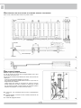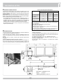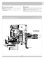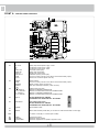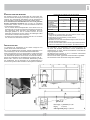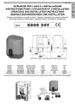
1
R50 OPERATORE PER PORTONI INDUSTRIALI OPERATEUR POUR PORTAILS INDUSTRIELS OPERATOR FOR INDUSTRIAL DOORS TORANTRIEB FÜR INDUSTRIETORE Operatore Operateur Operator Torantrieb Alimentazione Alimentation Power Supply Stromspannung Peso max cancello Poids maxi portail Max gate weight Max Torgewicht codice code code code R50 230V 50/60Hz 2000 kg / 4460 lbs AA21580 ITALIANO pag. 04 / FRANÇAIS pag. 14 / ENGLISH page 24 / DEUTSCH pag. 34 I F ISTRUZIONI DI SICUREZZA IMPORTANTI PER L’INSTALLAZIONE - ATTENZIONE PER LA SICUREZZA DELLE PERSONE É IMPORTANTE CHE VENGANO SEGUITE TUTTE LE ISTRUZIONI INSTRUCTIONS DE SECURITE IMPORTANTES POUR L’INSTALLATION - ATTENTION POUR LA SECURITE DES PERSONNES IL EST IMPORTANT QUE TOUTES LES INSTRUCTIONS SOIENT SUIVIES SUIVRE TOUTES LES INSTRUCTIONS D’INSTALLATION SEGUIRE TUTTE LE ISTRUZIONI DI INSTALLAZIONE 1° - Q uesto libretto d’istruzioni è rivolto esclusivamente a del personale specializzato che sia a conoscenza dei criteri costruttivi e dei dispositivi di protezione contro gli infortuni per i cancelli, le porte e i portoni motorizzati (attenersi alle norme e alle leggi vigenti). 2° - L’installatore dovrà rilasciare all’utente finale un libretto di istruzioni in accordo alla EN 12635. 3° - L’installatore prima di procedere con l’installazione deve prevedere l’analisi dei rischi della chiusura automatizzata finale e la messa in sicurezza dei punti pericolosi identificati (seguendo le norme EN 12453/EN 12445). 4° - Il cablaggio dei vari componenti elettrici esterni all’operatore (ad esempio fotocellule, lampeggianti, ecc.) deve essere effettuato secondo la EN 60204-1 e le modifiche a questa apportate dal punto 5.2.2 della EN 12453. 5° - L’eventuale montaggio di una pulsantiera per il comando manuale del movimento deve essere fatto posizionando la pulsantiera in modo che chi la aziona non si trovi in posizione pericolosa; inoltre si dovrà fare in modo che sia ridotto il rischio di azionamento accidentale dei pulsanti. 6° - Tenete i comandi dell’automatismo (pulsantiera, telecomando etc.) fuori dalla portata dei bambini. I comandi devono essere posti ad un’altezza minima di 1,5m dal suolo e fuori dal raggio d’azione delle parti mobili. 7° - Prima di eseguire qualsiasi operazione di installazione, regolazione, manutenzione dell’impianto, togliere la tensione agendo sull’apposito interruttore magnetotermico collegato a monte dello stesso. 1° - C e livret d’instructions est adressé exclusivement à un personnel spécialisé qui connaît les critères de construction et les dispositifs de protection contre les accidents concernant les portails, les portes et les grandes portes motorisés (s’en tenir aux normes et aux lois en vigueur). 2° - L’installateur devra délivrer à l’utilisateur final un livret d’instruction en accord à la EN 12635. 3° - L’installateur avant de procéder à l’installation, doit prévoir l’analyse des risques de la fermeture automatisée finale et la mise en sécurité des points identifiés dangereux (en suivant les normes EN 12453/EN 12445). 4° - Le câblage des divers composants électriques externes à l’opérateur (par exemple photocellules, clignotants, etc) doit être effectué selon la EN 60204-1 et les modifications apportées à celle-ci dans le point 5.2.2 de la EN 12453. 5° - Le montage éventuel d’un tableau pour la commande manuelle du mouvement doit être fait en positionnant le tableau de façon à ce que la personne qui l’actionne ne se trouve pas en position de danger ; de plus, il faudra faire en sorte que le risque d’actionnement accidentel des boutons soit réduit. 6° - Tenir les commandes de l’automatisme (tableau, télécommande, etc) hors de portée des enfants. Les commandes doivent être placées à une hauteur minimum de 1,5 m du sol et hors du rayon d’action des parties mobiles. 7° - Avant l’exécution de toute opération d’installation, de réglage, d’entretien de l’installation, couper le courant en agissant sur l’interrupteur magnétothermique à cet effet, branché en amont de l’installation. LA DITTA RIB NON ACCETTA NESSUNA RESPONSABILITÀ per eventuali danni provocati dalla mancata osservanza nell’installazione delle norme di sicurezza e delle leggi attualmente in vigore. LA SOCIETE RIB N’ACCEPTE AUCUNE RESPONSABILITE pour d’éventuels dommages provoqués par la non-observation dans l’installation, des normes de sécurité et des lois actuellement en vigueur. CONSERVARE CON CURA QUESTE ISTRUZIONI CONSERVER SOIGNEUSEMENT CES INSTRUCTIONS 1° - S e non é previsto nel quadro elettronico, installare a monte della medesima un’interruttore di tipo magnetotermico (onnipolare con apertura minima dei contatti pari a 3mm) che riporti un marchio di conformità alle normative internazionali. Tale dispositivo deve essere protetto contro la richiusura accidentale (ad esempio installandolo dentro quadro chiuso a chiave). 2° - Per la sezione ed il tipo dei cavi RIB consiglia di utilizzare un cavo di tipo H05RN-F con sezione minima di 1,5 mm2 e comunque di attenersi alla norma IEC 364 e alle norme di installazione vigenti nel proprio Paese. 3° - Posizionamento di un’eventuale coppia di fotocellule: il raggio delle fotocellule deve essere ad un’altezza non superiore a 70 cm dal suolo e ad una distanza dal piano di movimento dell’anta non superiore a 20 cm. Il loro corretto funzionamento deve essere verificato a fine installazione in accordo al punto 7.2.1 della EN 12445. 4° - Per il soddisfacimento dei limiti imposti dalla EN 12453, se la forza di picco supera il limite normativo di 400 N è necessario ricorrere alla rilevazione di presenza attiva sull’intera altezza del cancello (fino a 2,5m max) - Le fotocellule in questo caso sono da applicare all’esterno tra le colonne ed all’interno per tutta la corsa della parte mobile ogni 60÷70 cm per tutta l’altezza delle colonne del cancello fino ad un massimo di 2,5 m (EN 12445 punto 7.3.2.1) - es. colonne alte 2,2 m => 6 coppie di fotocellule - 3 interne e 3 esterne (meglio se dotate di sincronismo - 6 FIT SYNCRO con 2 TX SYNCRO). 1° - S i la centrale électrique ne dispose d’aucun interrupteur, il faut en installer un de type magnétothermique en amont de cette dernière (omnipolaire avec ouverture minimale des contacts correspondant à 3mm); la marque de cet interrupteur devra être en conformité avec les normes internationales. Ce dispositif doit être protégé contre toute remise en fonction accidentelle (ex. en l’installant dans un coffre fermant à clé). 2° - En ce qui concerne la section et le type des câbles, le conseil de RIB est celui d’utiliser un câble de type H05RN-F présentant une section minimale de 1,5 mm2 et, quoi qu’il en soit, de se conformer à la norme IEC 364, ainsi qu’aux normes d’installation en vigueur dans le pays de destination. 3° - Positionnement d’un éventuel jeu de photocellules : le faisceau des photocellules ne doit pas être à une hauteur supérieure à 70 cm du sol et 20 cm du bord du vantail. Leur correct effectivité fonctionnement doit être vérifié terminant l’installation, selon le point de la 7.2.1 de la EN 12445. 4° - Afin de satisfaire aux limites imposées par la norme EN 12453, si la force d’impact dépasse la limite de 400N, il sera nécessaire de détecter une présence sur la hauteur totale du portail (jusqu’à un maximum de 2,5m) - Les cellules photo-électriques dans ce casci doivent être s’appliquent extérieurement entre les colums et intérieurement pour toute la course de la pièce de mobil chaque 60÷70cm pour toute la taille de la colonne de la porte jusqu’à un maximum de 2,5m (EN 12445 point 7.3.2.1) - exemple: taille 2,2m de colonne = > 6 copies des cellules photo-électriques - 3 internes et 3 externes (meilleur si complet du dispositif de syncronism - FIT SYNCRO avec TX SYNCRO). N.B.: É obbligatoria la messa a terra dell’impianto I dati descritti nel presente manuale sono puramente indicativi. RIB si riserva di modificarli in qualsiasi momento. Realizzare l’impianto in ottemperanza alle norme ed alle leggi vigenti. N.B.:La mise à terre de l’installation est obligatoire. Les données figurant dans le présent manuel sont fournies à titre purement indicatif. RIB se réserve le droit de les modifier à tout moment, sans aucun préavis. Effectuer l’installation en conformité avec les normes et les lois en vigueur. 2 G B D IMPORTANT SAFETY INSTRUCTIONS FOR THE INSTALLATION - ATTENTION FOR THE SAFETY OF THE PEOPLE IT IS IMPORTANT TO FOLLOW ALL THE INSTRUCTIONS. WICHTIGE SICHERHEITS ANLEITUNGEN FÜR DIE INSTALLATIONEN - ACHTUNG FÜR DIE SICHERHEIT DER PERSONEN IST ES WICHTIG, DASS ALLE ANWEISUNGEN GENAU AUSGEFÜHRT WERDEN ALLE INSTALLATIONSANLEITUNGEN BEFOLGEN FOLLOW ALL INSTALLATION INSTRUCTIONS 1° - D iese Betriebsanleitung dient ausschließlich dem Fachpersonal, welche die Konstruktionskriterien und die Sicherheits-Vorschriften gegen Unfälle für Tore, Türen und automatische Tore kennt (geltende Normen und Gesetze beachten und befolgen). 2° - Der Monteur muss dem Endkunde eine Betriebsanleitung in Übereinkunft der EN12635 überreichen. 3° - Vor der Installierung muss für die automatische Schließung und zur Sicherheitsgewährung der identifizierten kritischen Punkte, eine Risiko Analyse vorgenommen werden mit der entsprechenden Behebung der identifizierten, gefährlichen Punkte. (die Normen EN 12453/EN 12445 befolgend). 4° - Die Verkabelung der verschiedenen externen elektrischen Komponenten zum Operator (z.B. Fotozellen, Blinker etc.) muss nach EN 60204-1 ausgeführt werden, Änderungen davon nach Punkt 5.2.2 der EN 12453. 5° - Die eventuelle Montage einer Schalttafel für den manuellen Bewegungsbefehl muss so angebracht werden, dass der Benutzer sich nicht in einer Gefahrenzone befindet, und dass, das Risiko einer zufälligen nicht gewollten Aktivierung von Schaltern gering ist. 6° - Alle Steuerungselemente (Schalttafel, Fernbedienung etc.) gehören nicht in Reichweite von Kindern. Die Kommandos müssen min. 1,5 m ab Boden und außerhalb des Aktionsbereiches der mobilen Teile angebracht werden. 7° - Vor jeglichem Eingriff, sei es Installation, Regulation oder Wartung der Anlage, muss vorher die Stromzufuhr unterbrochen werden, den dafür bestimmten Magnetthermo-Schalter drücken, der am Eingang der Anlage installiert ist. 1° - T his handbook is exclusively addressed to the specialized personnel who knows the constructive criteria and the protection devices against the accidents for motorized gates, doors and main doors (follow the standards and the laws in force). 2° - The installer will have to issue to the final user a handbook in accordance with the EN 12635. 3° - Before proceeding with the installation, the installer must forecast the risks analysis of the final automatized closing and the safety of the identified dangerous points (following the standards EN 12453/EN 12445). 4° - The wiring harness of the different electric components external to the operator (for example photoelectric cells, flashlights etc.) must be carried out according to the EN 60204-1 and the modifications to it done in the point 5.2.2 of the EN 12453. 5° - The possible assembly of a keyboard for the manual control of the movement must be done by positioning the keyboard so that the person operating it does not find himself in a dangerous position; moreover, the risk of accidental activation of the buttons must be reduced. 6° - Keep the automatism controls (push-button panel, remote control etc.) out of the children way. The controls must be placed at a minimum height of 1,5m from the ground and outside the range of the mobile parts. 7° - Before carrying out any installation, regulation or maintenance operation of the system, take off the voltage by operating on the special magnetothermic switch connected upstream it. THE RIB COMPANY DOES NOT ACCEPT ANY RESPONSIBILITY for possible damages caused by the non observance during the installation of the safety standards and of the laws in force at present. DIE FIRMA RIB ÜBERNIMMT KEINE VERANTWORTUNG für eventuelle Schäden, die entstehen können, wenn die Installierungsvorschriften die den gültigen Sicherheitsnormen entsprechen, nicht eingehalten werden. KEEP THESE INSTRUCTIONS WITH CARE INSTALLATIONSVORSCHRIFTEN BEACHTET WERDEN 1° - Install a thermal magnetic switch (omnipolar, with a minimum contact opening of 3 mm) before the control board, in case this is not provided with it. The switch shall be guaranteed by a mark of compliance with international standards. Such a device must be protected against accidental closing (e.g. Installing it inside the control panel key locked container). 2° - As far as the cable section and the cable kind are concerned, RIB suggests to use an H05RN-F cable, with a minimum section of 1,5mm2, and to follow, In any case, the IEC 364 standard and Installation regulations In force In your Country. 3° - Positioning of an eventual pair of photocells: The beam of the photocells must be at an height not above the 70 cm from the ground, and, should not be more than 20 cm away from the axis of operation of the gate (Sliding track for sliding gate or door, and the hinges for the swing gate). In accordance with the point 7.2.1 of EN 12445 their correct functioning must be checked once the whole installation has been completed. 4° - In order to comply with the limits defined by the EN 12453 norm, if the peak force is higher than the limit of 400N set by the norm, it is necessary to use an active obstacle detection system on the whole height of the gate (up to a maximum of 2,5m) - The photocells in this case must be apply externally between the colums and internally for all the race of the mobil part every 60÷70cm for all the height of the column of the gate up to a maximum of 2,5m (EN 12445 point 7.3.2.1). example: column height 2,2m => 6 copies of photocells - 3 internal and 3 external (better if complete of syncronism feature - FIT SYNCRO with TX SYNCRO). 1° - W enn nicht bereits an der elektrischen Schaltzentrale vorgesehen, muss vor der Schaltzentrale ein thermomagnetischer Schalter installiert werden (omnipolar, mit einer minimalen Kontaktöffnung von 3 mm), der ein von den internationalen Normen anerkanntes Konformitätszeichen besitzt. Solch ein Geraet muss vor Vandalismus geschuetzt werden(z.B.mit einen Schluesselkatsten in einem Panzergehaeuse) 2° - RIB empfiehlt den Kabeltyp H05RN-F mit einem minimalen Querschnitt von 1,5mm2 generell sollten die Normative IEC 364 und alle anderen geltenden Montagenormen des Bestimmungslandes eingehalten werden. 3°- Position des ersten paar Fotozellen: Der sollten nicht hoeher als 70cm vom Boden sein, und sollte nicht mehr als 20 cm entfernt von der Achse des Tores sitzen (das gilt fuer Schiebe und Drehtore). In Übereinstimmung mit dem Punkt 7.2.1 der EN 12445 Norm, ihr korrektes Funktionieren muß einmal überprüft werden. 4°- In Einklang mit der Norm EN12453, ist es bei Toren notwendig eine komplette Sicherheitslieiste zu installieren, bei denen mehr als 400N Kraft aufgewand werden muessen, um das Tor zum anhalten zu bringen (Maximum von 2,5m anwenden) Die Fotozellen müssen in diesem Fall sein beantragen außen zwischen den colums und innerlich das ganzes Rennen des mobil Teils jede 60÷70cm für die ganze Höhe der Spalte des Gatters bis zu einem Maximum von 2,5m - EN 12445 Punkt 7.3.2.1). Beispiel: Spalte Höhe 2,2m => 6 Kopien von Fotozellen - 3 intern und 3 extern (besser, wenn komplett von der syncronism Eigenschaft FIT SYNCRO mit TX SYNCRO). ANMERKUNG: Die Erdung der Anlage ist obligatorisch Die in diesem Handbuch aufgeführten Daten sind ausschließlich empfohlene Werte. RIB behält sich das Recht vor, das Produkt zu jedem Zeitpunkt zu modifizieren. Die Anlage muss in Übereinstimmung mit den gültigen Normen und Gesetzen montiert werden. N.B.: The system must be grounded Data described by this manual are only Indicative and RIB reserves to modify them at any time. Install the system complying with current standards and regulations. 3 I LAYOUT IMPIANTO CARATTERISTICHE TECNICHE 2 Operatore per movimentare portoni a battente ad uso industriale del peso massimo complessivo di 2000 kg. R50 è un operatore irreversibile la cui forza di traino è variabile con la pressione, regolabile, che le ruote motrici esercitano sul pavimento. Le ruote motrici che aderiscono al terreno hanno la possibilità di superare un dislivello di circa 6 cm poichè il gruppo motoriduttore scorre su una guida verticale. La pressione tra ruote motrici e terreno varia da 30 fino ad un massimo di 130 kg ed è mantenuta da una molla registrabile. 3 6 5 CARATTERISTICHE TECNICHE 5 1 4 6 1 2 3 4 5 6 - Lunghezza max. anta m 10 Peso max cancello kg 2000 Tempo medio di apertura 90° s. 78 Velocità traino m/s. 0,180 (50Hz) - 0,216 (60Hz) 230V~ Alimentazione e frequenza 4 1 5 R50 Operatore R50 Antenna radio Lampeggiatore Fotocellula esterna Fotocellule interna Selettore a chiave 1 Misure in mm 4 60Hz Potenza motore W 437 511 Assorbimento A 1,96 2,32 Condensatore mF 16 120V~ 60Hz Alimentazione e frequenza 5 50Hz Potenza motore W 251 Assorbimento A 2,26 Condensatore mF 40 Cicli normativi 230/50-60 n° 3 - 78s/2s Cicli normativi120/60 n° 8 - 78s/2s Cicli giornalieri consigliati n° 300 Servizio 60% Cicli consecutivi garantiti n° 4/78s Lubrificazione a grasso COMLUBE LHITGREASE EP/GR.2 Peso motore kg 45 Temperatura di lavoro °C -10 ÷ +55°C Grado di protezione IP 54 2 I INSTALLAZIONE R50 CONTROLLO PRE-INSTALLAZIONE Componenti da installare secondo la norma EN12453 TIPO DI COMANDO Le ante devono essere solidamente fissate ai cardini delle colonne, non devono flettere durante il movimento e devono muoversi senza attriti. Il terreno sul quale vanno ad agire le ruote dell’R50 deve essere compatto, non friabile e con un’inclinazione minima. È obbligatorio uniformare le caratteristiche del cancello alle norme e leggi vigenti. La porta può essere automatizzata solo se in buono stato e se rispondente alla norma EN 12604. - L’anta non deve presentare porte pedonali. In caso contrario occorrerà prendere opportune precauzioni in accordo al punto 5.4.1 della EN12453 (ad esempio impedire il movimento del motore quando il portoncino è aperto, grazie ad un microinterruttore opportunamente collegato in centralina). - Non bisogna generare punti di intrappolamento (ad esempio tra anta aperta del cancello e cancellata). - Non devono essere presenti fermi meccanici al di sopra del cancello perché non sono sufficientemente sicuri. a uomo presente a impulsi in vista (es. sensore) a impulsi non in vista (es. telecomando) automatico USO DELLA CHIUSURA Persone esperte Persone esperte Uso illimitato (fuori da area pubblica*) (area pubblica) A B non possibile C o E C o E C e D, o E C o E C e D, o E C e D, o E C e D, o E C e D, o E C e D, o E * esempio tipico sono le chiusure che non accedono a pubblica via A: Pulsante di comando a uomo presente (cioè ad azione mantenuta), come cod. ACG2013. B: Selettore a chiave a uomo presente, come cod. ACG1010. C: Regolazione della forza del motore. D: Coste e/o altri dispositivi di limitazione delle forze entro i limiti della norma EN12453 - Appendice A. E: Fotocellule, es. cod. ACG8026 (Da applicare ogni 60÷70 cm per tutta l’altezza della colonna del cancello fino ad un massimo di 2,5 m - EN 12445 punto 7.3.2.1) INSTALLAZIONE DELL’R50 È necessario che il pavimento sia compatto e senza forti dislivelli almeno per il tratto percorso dalle ruote. Posizionare il cancello a metà corsa, fissare la piastra porta riduttore in punta all’anta facendo appoggiare le ruote motrici al terreno. Per far ciò è necessario praticare quattro fori nell’anta di Ø 6,5 mm e poi filettarli con un maschio M8, quindi utilizzare quattro viti M8 e stringere con una chiave n° 13. Eliminare in seguito la spina elastica che blocca lo scorrimento delle ruote (Fig. 6). Qualora le ruote motrici dovessero slittare sul pavimento durante la marcia, agire sulle ghiere di registro della molla girandole in senso orario per aumentare la pressione tra ruote e terreno. Per evitare che le ruote si deteriorino durante il movimento è necessario svitare i dadi (D) con una chiave n° 13 e inclinare le ruote dei motoriduttori in modo che l’asse delle ruote gommate attraversi il centro del cardine dell’anta. L’inclinazione delle ruote è variabile da 0° a 7,5°. In seguito ribloccare i due dadi. L’R50 ha in dotazione due finecorsa corazzati stagni utilizzabili per delimitare elettricamente la corsa del cancello. Il posizionamento di questi finecorsa è a discrezione dell’installatore. D B min [m] = (0,205+A) / 0,12 B [m] = 0,9 x L Tempo di apertura [sec] = 7,85 x L 5 3 I APPLICAZIONE DELL’R50 A PORTONE CON PIÙ ANTE SCORREVOLI In questo caso l’R50 dovrà essere montato sulla prima anta Olive Finecorsa Ruote Ø120 Interno 250 Box Finecorsa Box Guida Fermo meccanico Esterno 4 5 SBLOCCO DI EMERGENZA Da effettuare dopo aver tolto l’alimentazione elettrica al motore. In caso di mancanza di energia elettrica sollevare la maniglia laterale per ottenere il sollevamento delle ruote dal terreno. Per poter eseguire in modo sicuro la movimentazione manuale dell’anta occorre verificare che: - sull’anta siano presenti maniglie idonee; - tali maniglie siano posizionate in modo da non creare punti di pericolo durante il loro utilizzo; - lo sforzo manuale per muovere l’anta non superi i 225N per i cancelli posti su siti privati ed i 390N per i cancelli posti su siti commerciali ed industriali (valori indicati nel punto 5.3.5 della norma EN 12453). A : Asta B C con corsa max 6 cm (sollecitazioni di buche o dislivello del pavimento). : Spina elastica da rimuovere a fissaggio ultimato per liberare la molla. : Ghiere di registrazione molla. 6 6 I SICUREZZE ELETTRICHE MANUTENZIONE Realizzare l’impianto in ottemperanza alle norme ed alle leggi vigenti. Si consiglia l’utilizzo del quadro elettronico di comando T2. Per i collegamenti ed i dati tecnici degli accessori attenersi ai relativi libretti. Da effettuare da parte di personale specializzato dopo aver tolto l’alimentazione elettrica al motore. Ogni fine settimana pulire accuratamente la superficie di scorrimento delle ruote. Ogni sei mesi ritarare la pressione delle ruote sul pavimento e controllare lo stato delle ruote motrici. Ogni due anni è consigliabile una revisione con sostituzione dell’olio. T2 cod. BC07086 T2 CRX cod. BC07085 COLLEGAMENTI ELETTRICI R50 LSC1 - finecorsa chiude M1 LSO1 - finecorsa apre M1 LSC2 - finecorsa chiude M2 LSO2 - finecorsa apre M2 LAMPEGGIATORE LSO2 LSC2 ANTENNA LSO1 CALZA ANTENNA LSC1 SPIA R=2,2KΩ + BUZZER - 12 Vdc per AUTOTEST + PER COSTA 12 Vdc per + ACCESSORI - FOTOCELLULE ALIMENTAZIONE COSTE + PASSO PASSO PEDONALE COMUNE 7 MOTOR 2 CONDENSATORE M2 MOTOR 1 CONDENSATORE M1 I A - CONNESSIONI ON JP17 TR2 TR1 S3 J8 J5 JP1 JP2 J4 JP3 J6 J1 J3 J7 J2 J1 N -L1 Alimentazione 230 Vac 50/60 Hz (120V/60Hz a richiesta) J2 D+ TEST D + D - PHOT. NC EDGE NC K BUTT. PED. BUTT. COM LOCK Positivo per alimentazione autotest costa a 12Vdc Positivo per alimentazione accessori a 12Vdc Negativo per alimentazione accessori a 12Vdc Contatto fotocellule (NC) Contatto Costa (NC) Contatto impulso singolo (NA) Contatto comando apertura pedonale (NA) Comune dei contatti Collegamento elettroserratura (MAX 15W 12V) J3 AERIAL COM BUZZER SIGNAL Antenna radio Comune dei contatti Collegamento segnalatore sonoro (12Vdc max 200 mA) Spia cancello aperto 12Vdc U - MOTOR 2 V-W - MOTOR 2 U - MOTOR 1 V-W - MOTOR 1 Lampeggiatore (max 40W ) COLLEGAMENTO COMUNE MOTORE 2 COLLEGAMENTO INVERTITORI E CONDENSATORE MOTORE 2 COLLEGAMENTO COMUNE MOTORE 1 COLLEGAMENTO INVERTITORI E CONDENSATORE MOTORE 1 J4 J5 SW T2 NON TOCCARE IL PONTICELLO ! SE VIENE RIMOSSO L’OPERATORE NON FUNZIONA! J6 SW RADIO ( solo per modelli CRX) NON TOCCARE IL PONTICELLO ! SE VIENE RIMOSSO IL SISTEMA RADIO NON FUNZIONA! J7 PROBE Non disponibile per R50 J8 RADIO Modulo radio incorporato (modello CRX), o connettore per radio ricevitore RIB ad innesto con alimentazione a 12 Vdc. Selezione funzionamento con 1 o 2 motori JP17 S3 TR1 TR2 PROG TORQUE LOW SPEED Pulsante per la programmazione Regolatore elettronico della forza Regolatore elettronico della velocità lenta in accostamento con DIP 7 ON 8 I B - MICROINTERRUTTORI DI GESTIONE FUSIBILI F1 T100mA Fusibile di protezione accessori F2 5A Fusibile di protezione motori DIP 1 (ON) - CONTROLLO SENSO DI ROTAZIONE DEL/DEI MOTORE/I (PUNTO C) DIP 2 (ON) - PROGRAMMAZIONE TEMPI (PUNTO D) DIP 1-2MEMORIZZAZIONE/CANCELLAZIONE CODICI RADIO COMANDO APERTURA TOTALE (DIP 1 ON seguito da DIP 2 ON) (PUNTO E) SOLO PER MODELLI CRX DIP 1-3MEMORIZZAZIONE/CANCELLAZIONE CODICI RADIO COMANDO APERTURA PEDONALE (DIP 1 ON seguito da DIP 3 ON) (PUNTO F) SOLO PER MODELLI CRX DIP 2-1PROGRAMMAZIONE TEMPI APERTURA PEDONALE (PUNTO D) DIP 3Tempo di attesa prima della chiusura automatica totale e pedonale(ON) DIP 4Fotocellule sempre attive (OFF) - Fotocellule attive solo in chiusura (ON) DIP 5 Prelampeggio (ON) - Lampeggio normale (OFF) DIP 6Comando impulso singolo (K BUTT) e Ricevitore radio passo passo (OFF) automatico (ON) DIP 7 Rallentamento (ON - attivato) DIP 8 Abilitazione serratura elettrica (ON-attivato) DIP 9Abilitazione colpo di sgancio serratura elettrica e facilitazione sblocco (ON attivata) DIP 10 Abilitazione colpo di aggancio serratura elettrica (ON - attivato) DIP 11 Se OFF la funzione black out non é attiva Se ON la funzione black out é attiva (vedi TAB 1) DIP 12 Gestione richiusura immediata dopo il transito da fotocellule ON - Abilitata OFF - Disabilitata DIP 13Abilitazione TEST monitoraggio costa (ON abilitato, OFF disabilitato) DIP 14 OFF OBBLIGATORIO PER MOTORE R50 DIP 15 ON OBBLIGATORIO PER MOTORE R50 DIP 16 ON OBBLIGATORIO PER MOTORE R50 JP 17Selezione funzionamento con 1 o 2 motori (di default jumper chiuso 2 motori) JP1 => Verificare che il ponticello sia inserito! JP2 => Verificare che il ponticello sia inserito! JP3 => Verificare che il ponticello sia inserito! C - CONTROLLO SENSO DI ROTAZIONE DEI MOTORI Questo controllo ha il compito di agevolare l’installatore durante la messa in opera dell’impianto, o per eventuali controlli successivi. 1 - Posizionare il cancello a metà corsa utilizzando lo sblocco manuale. 2 - Mettere il DIP1 in posizione ON => il led rosso DL1 inizia a lampeggiare. 3 - Premere e mantenere premuto il pulsante PROG => I LED VERDI DL3 e DL5 si accendono e il cancello si dovrà aprire con sfasamento fisso delle ante di due secondi (il movimento é eseguito ad uomo presente, apre-chiude-apreetc...). Verificare il movimento delle ante e regolare la posizione dei finecorsa meccanici di apertura. Se uno dei due o tutti e due i motori chiudono invece di aprire, rilasciare il pulsante PROG ed invertire i due invertitori (V1/2 e W1/2) del/i motore/i interessato/i. 4 - Premere il pulsante PROG e mantenerlo premuto per CHIUDERE completamente il cancello - Quando si accendono i LED rossi DL4 e DL6, le ante stanno chiudendo (con uno sfasamento di 4 secondi). Verificare il movimento delle ante e regolare la posizione dei finecorsa meccanici di chiusura. 5 - Dopo 3 sec. e fino a 10 sec. di movimento in apertura o in chiusura, si innesca automaticamente la forza elettronica regolabile agendo sul trimmer TORQUE (girare il trimmer in senso orario per dare maggior forza). 6 - Dopo 10 secondi di lavoro i motori rallentano (se DIP 7 su ON). Regolate il rallentamento dei motori in accostamento agendo sul trimmer LOW SPEED. 7 - Chiudere completamente il cancello. 8 - Spostare il DIP 1 su OFF. Il led rosso DL1 si spegnerà. N.B.: Durante questo controllo le fotocellule e le coste non sono attive. In questa modalità il radiocomando non può funzionare. D - PROGRAMMAZIONE TEMPI PER 2 MOTORI (#) 1 - Il cancello deve essere completamente chiuso. 2 - Mettete il microinterruttore DIP 2 su ON => Il led DL1 emetterà dei lampeggi brevi. 3 - Premete il pulsante PROG. => M1 apre. 4 - Raggiunto il fermo meccanico di apertura, dopo un secondo premete il pulsante PROG. => M1 si ferma e M2 apre. 5 - Raggiunto il fermo meccanico di apertura => dopo 1 secondo premete il pulsante PROG. => M2 si ferma => Nello stesso momento si attiva il conteggio del tempo d’attesa prima della chiusura automatica (max 5 minuti). 6 - Premete il pulsante PROG. => il conteggio del tempo d’attesa prima della chiusura automatica si ferma e M2 chiude. 7 - Premete il pulsante PROG. => M1 chiude determinando la sfasamento fra M2 e M1. Nello stesso istante il led DL1 smetterà di lampeggiare segnalando l’uscita dalla procedura di apprendimento. Da questo momento le sicurezze o altri comandi del cancello funzioneranno normalmente (inversioni, stop, allarmi, ecc....). 8 - Finito il conteggio del tempo il cancello si ferma. 9 - A FINE PROGRAMMAZIONE RIMETTERE IL DIP 2 SU OFF. NOTA: Il rallentamento viene determinato automaticamente dal quadro elettronico in fase di programmazione tempi, e viene attivato a circa 50÷60 cm prima del raggiungimento dei finecorsa meccanici di apertura o chiusura. TORQUE TR1 - REGOLATORE ELETTRONICO DELLA FORZA La regolazione della forza viene fatta ruotando il Trimmer TORQUE che serve a variare la tensione di uscita ai capi del motore (ruotando in senso orario si da più forza al motore). Tale forza si include automaticamente dopo 3 secondi dall’inizio di ogni manovra. Questo per dare il massimo di spunto al motore al momento della partenza. NOTA: SE QUESTO TRIMMER VIENE REGOLATO DOPO AVERE ESEGUITO LA PROCEDURA DI PROGRAMMAZIONE, È POSSIBILE CHE LA MISURA DI INIZIO RALLENTAMENTO SUBISCA DELLE VARIAZIONI (IN PIU’ O IN MENO RISPETTO ALLA PRECEDENTE), PERTANTO SE SI ESEGUE UNA NUOVA REGOLAZIONE DEL TRIMMER, SI CONSIGLIA DI RIESEGUIRE LA PROGRAMMAZIONE DEI TEMPI. RALLENTAMENTO - LOW SPEED TR2 La regolazione della velocità lenta viene eseguita agendo sul Trimmer LOW SPEED tramite il quale si varia la tensione di uscita ai capi del/dei motore/i (ruotandolo in senso orario si aumenta la velocità). La regolazione viene eseguita per determinare la corretta velocità di fine apertura e fine chiusura in base alla struttura del cancello o in presenza di leggeri attriti che potrebbero compromettere il corretto funzionamento del sistema. Il rallentamento viene determinato automaticamente dal quadro elettronico in fase di programmazione tempi, e viene attivato a circa 50÷60 cm prima del raggiungimento del finecorsa meccanico di apertura o di chiusura. ATTENZIONE: UTILIZZO CON MOTORI IDRAULICI Se si utilizzano dei motori idraulici la fase di RALLENTAMENTO potrebbe NON funzionare correttamente, in tal caso è opportuno disabilitarla posizionando il DIP 7 in OFF. D - PROGRAMMAZIONE TEMPI PER 1 MOTORE (#) CON JUMPER 17 (jumper APERTO) 1 - Il cancello deve essere completamente chiuso. 2 - Mettete il microinterruttore DIP 2 su ON => Il led DL1 emetterà dei lampeggi brevi. 3 - Premete il pulsante PROG. => M1 apre. 4 - Raggiunto il fermo meccanico di apertura, dopo un secondo premete il pulsante PROG. => M1 si ferma e si attiva il conteggio del tempo d’attesa prima della chiusura automatica (max 5 minuti). 5 - Premete il pulsante PROG. => si ferma il conteggio del tempo d’attesa prima della chiusura automatica e M1 chiude. Nello stesso istante il led DL1 smetterà di lampeggiare segnalando l’uscita dalla procedura di apprendimento. Da questo momento le sicurezze o altri comandi del cancello funzioneranno normalmente (inversioni, stop, allarmi, ecc....). 6 - Finito il conteggio del tempo il cancello si ferma. 7 - A FINE PROGRAMMAZIONE RIMETTERE IL DIP 2 SU OFF. SEGNALAZIONI LED DL1 - (Rosso) - Programmazione attivata DL2 - (Verde) - Programmazione radio attivata (solo nei modelli CRX) DL3 - (Verde) - Cancello in apertura M2 DL4 - (Rosso) - Cancello in chiusura M2 DL5 - (Verde) - Cancello in apertura M1 DL6 - (Rosso) - Cancello in chiusura M1 DL7 - (Rosso) - Contatto fotocellule (NC) DL8 - (Rosso) - Contatto coste (NC) 9 I D - PROGRAMMAZIONE TEMPI APERTURA PEDONALE (#) 7 - Fine procedura. PROCEDURA CANCELLAZIONE DI TUTTI I CODICI RADIO DEDICATI ALL’APERTURA PEDONALE La cancellazione può essere eseguita solo a cancello fermo. 1 - Posizionare il DIP 1 su ON e successivamente il DIP 3 su ON. 2 - Il led rosso DL1 di programmazione lampeggia con frequenza di 1 sec. ON e 1 sec. OFF per 10 secondi. 3 - Premere e mantenere premuto il pulsante PROG per 5 secondi. La cancellazione della memoria viene segnalata da due lampeggi del led verde DL2. 4 - Il led rosso DL1 di programmazione rimane attivo ed è possibile inserire nuovi codici come da procedure sopra descritte. 5 - Riposizionare DIP 1 su OFF e DIP 3 su OFF. 6 - Fine procedura. SEGNALAZIONE MEMORIA SATURA CODICI RADIO DEDICATI ALL’APERTURA PEDONALE La segnalazione si può ottenere solo a cancello fermo. 1 - Posizionare il DIP 1 su ON e successivamente il DIP 3 su ON. 2 - Il led verde DL2 lampeggia per 6 volte segnalando memoria satura (64 codici presenti). 3 - Successivamente il led DL1 di programmazione rimane attivo per 10 secondi, consentendo un eventuale cancellazione totale dei codici. 4 - Riposizionare DIP 1 su OFF e DIP 3 su OFF. 5 - Fine procedura. A cancello chiuso: 1 - Mettere prima il DIP2 su ON (il led DL1 lampeggia velocemente) e dopo il DIP1 su ON (il led DL1 lampeggia lentamente). 2 - Premere il pulsante pedonale (COM-PED.BUTT) => Anta 1 apre. 3 - Premere il pulsante pedonale per arrestare la corsa (definendo così l’apertura dell’anta 1). 4 - Attendere il tempo che si vuole rimanga aperto (escludibile con il DIP3 su OFF), quindi premere il pulsante pedonale per avviare la chiusura. 5 - Al raggiungimento della chiusura rimettere i DIP1 e 2 su OFF. (#) DURANTE LA PROGRAMMAZIONE LE SICUREZZE SONO ATTIVE ED IL LORO INTERVENTO FERMA LA PROGRAMMAZIONE (IL LED DL1 DA LAMPEGGIANTE RIMANE ACCESO FISSO). PER RIPETERE LA PROGRAMMAZIONE POSIZIONARE I DIP 1 E 2 SU OFF, CHIUDERE IL CANCELLO TRAMITE PROCEDURA “CONTROLLO SENSO DI ROTAZIONE DEI MOTORI” E RIPETERE LA PROGRAMMAZIONE SCELTA. E - PROGRAMMAZIONE CODICI RADIO APERTURA TOTALE (62 CODICI MAX - SOLO MODELLI CRX) La programmazione può essere eseguita solo a cancello fermo. 1 - Posizionare DIP 1 su ON e successivamente il DIP 2 su ON. 2 - Il led rosso DL1 di programmazione lampeggia con frequenza di 1 sec. ON e 1 sec. OFF per 10 secondi. 3 - Premere il tasto del telecomando (normalmente il canale A) entro i 10 secondi impostati. Se il telecomando viene correttamente memorizzato il led DL2 (verde) emette un lampeggio. 4 - Il tempo di programmazione dei codici si rinnova automaticamente per poter memorizzare il telecomando successivo. 5 - Per terminare la programmazione lasciare trascorrere 10 sec., oppure premere per un attimo il pulsante PROG. Il led rosso DL1 di programmazione smette di lampeggiare. 6 - Riposizionare DIP 1 su OFF e DIP 2 su OFF. 7 - Fine procedura. PROCEDURA CANCELLAZIONE DI TUTTI I CODICI RADIO DEDICATI ALL’APERTURA TOTALE La cancellazione può essere eseguita solo a cancello fermo. 1 - Posizionare il DIP 1 su ON e successivamente il DIP 2 su ON. 2 - Il led rosso DL1 di programmazione lampeggia con frequenza di 1 sec. ON e 1 sec. OFF per 10 secondi. 3 - Premere e mantenere premuto il pulsante PROG per 5 secondi. La cancellazione della memoria viene segnalata da due lampeggi del led verde DL2. 4 - Il led rosso DL1 di programmazione rimane attivo ed è possibile inserire nuovi codici come da procedure sopra descritte. 5 - Riposizionare DIP 1 su OFF e DIP 2 su OFF. 6 - Fine procedura. SEGNALAZIONE MEMORIA SATURA CODICI RADIO DEDICATI ALL’APERTURA TOTALE La segnalazione si può ottenere solo a cancello fermo. 1 - Posizionare il DIP 1 su ON e successivamente il DIP 2 su ON. 2 - Il led verde DL2 lampeggia per 6 volte segnalando memoria satura (64 codici presenti). 3 - Successivamente il led DL1 di programmazione rimane attivo per 10 secondi, consentendo un eventuale cancellazione totale dei codici. 4 - Riposizionare DIP 1 su OFF e DIP 2 su OFF. 5 - Fine procedura. FUNZIONAMENTO ACCESSORI DI COMANDO ATTENZIONE: COLLEGARE ACCESSORI DI COMANDO SOLO SE IMPULSIVI. Assicurarsi che eventuali altri tipi di accessori di comando (per esempio sensori magnetici) siano programmati nella modalità IMPULSIVA, altrimenti attiverebbero la movimentazione del cancello senza sicurezze attive. PULSANTE DI COMANDO PASSO-PASSO (COM-K BUTTON) Se DIP6 su OFF => Esegue un comando ciclico dei comandi apre-stop-chiude-stop-apre ecc. Se DIP6 su ON => Esegue l’apertura a cancello chiuso. Se azionato durante il movimento di apertura non ha effetto. Se azionato a cancello aperto lo chiude e durante la chiusura se azionato lo fa riaprire. FUNZIONE OROLOGIO Se desiderate la funzione orologio dovete richiedere T2 con firmware 08. ATTENZIONE: UN OROLOGIO COLLEGATO A T2 con fw 09 o superiore COMPORTA IL MOVIMENTO AUTOMATICO DEL CANCELLO SENZA SICUREZZE ATTIVE ! La funzione orologio è utile nelle ore di punta, quando il traffico veicolare risulta rallentato (es. entrata/uscita operai, emergenze in zone residenziali o parcheggi e, temporaneamente, per traslochi). MODALITÁ DI APPLICAZIONE FUNZIONE OROLOGIO Richiedere T2 con firmware 08. Selezionare il funzionamento automatico DIP 6 OFF. Collegando un interruttore e/o un orologio di tipo giornaliero/settimanale (al posto o in parallelo al pulsante di apertura N.A. “COM-K-BUTTON”), è possibile aprire e mantenere aperta l’automazione finchè l’interruttore viene premuto o l’orologio rimane attivo. Ad automazione aperta vengono inibite tutte le funzioni di comando. Se la chiusura automatica è attiva, rilasciando l’interruttore, o allo scadere dell’ora impostata, si avrà la chiusura immediata dell’automazione, altrimenti sarà necessario dare un comando. F - PROGRAMMAZIONE CODICI RADIO APERTURA PEDONALE (62 CODICI MAX - SOLO MODELLI CRX) La programmazione può essere eseguita solo a cancello fermo. 1 - Posizionare DIP 1 su ON e successivamente il DIP 3 su ON. 2 - Il led rosso DL1 di programmazione lampeggia con frequenza di 1 sec. ON e 1 sec. OFF per 10 secondi. 3 - Premere il tasto del telecomando (normalmente il canale B) entro i 10 secondi impostati. Se il telecomando viene correttamente memorizzato il led DL2 (verde) emette un lampeggio. 4 - Il tempo di programmazione dei codici si rinnova automaticamente per poter memorizzare il telecomando successivo. 5 - Per terminare la programmazione lasciare trascorrere 10 sec., oppure premere per un attimo il pulsante PROG. Il led rosso DL1 di programmazione smette di lampeggiare. 6 - Riposizionare DIP 1 su OFF e DIP 3 su OFF. NOTA: SE IL LED DL1 CONTINUA A LAMPEGGIARE VELOCEMENTE, SIGNIFICA CHE IL DIP 1 RISULTA ANCORA POSIZIONATO IN ON E QUALSIASI MANOVRA VIENE NEGATA. TELECOMANDO Se DIP6 su OFF => Esegue un comando ciclico dei comandi apre-stop-chiude-stopapre-ecc. Se DIP6 su ON => Esegue l’apertura a cancello chiuso. Se azionato durante il movimento di apertura non ha effetto. Se azionato con cancello aperto, lo chiude. Se azionato durante il movimento di chiusura lo fa riaprire. CHIUSURA AUTOMATICA (TOTALE) I tempi di pausa prima di avere la chiusura automatica del cancello vengono registrati durante la programmazione dei tempi. Il tempo di pausa massimo è di 5 minuti. Il tempo di pausa è attivabile o disattivabile tramite DIP3 (ON attivo). 10 I apertura), la chiusura immediata viene esclusa e viene attivato il tempo di chiusura automatica (se DIP 3 ON). Se durante la chiusura si ha un transito veloce (es. pedone) il cancello riaprirà per due secondi per poi richiudere nuovamente. DIP 12 OFF => chiusura immediata dopo il transito dalle fotocellule disabilitata. N.B.: Si raccomanda di verificare la funzionalità delle fotocellule almeno ogni 6 mesi. PULSANTE APERTURA PEDONALE (COM-PED.BUTT.) Comando dedicato ad un’apertura parziale e alla sua richiusura. Durante l’apertura, la pausa o la chiusura pedonale, è possibile comandare l’apertura da qualsiasi comando collegato sulla scheda. Tramite DIP 6 è possibile scegliere la modalità di funzionamento del pulsante di comando pedonale. Se DIP6 su OFF => Esegue un comando ciclico dei comandi apre stop-chiude-stop ecc. Se DIP6 su ON => Esegue l’apertura a cancello chiuso. Se azionato durante il movimento di apertura non ha effetto. Se azionato a cancello aperto lo chiude e durante la chiusura, se azionato, lo fa riaprire. EDGE (COSTA) (COM-EDGE) Durante l’apertura, se impegnata, inverte il moto in chiusura. Durante la chiusura, se impegnata, inverte il moto in apertura. Se rimane impegnata dopo il primo impegno, esegue un’ulteriore inversione dopo 2 secondi, per poi eseguire un’ulteriore piccola inversione e quindi segnalare l’allarme di costa guasta o impegnata (contatto NO). Se la costa rimane impegnata (contatto NO) nessuna movimentazione è consentita. Se non usata, ponticellare i morsetti COM-EDGE. CHIUSURA AUTOMATICA PEDONALE I tempi di pausa prima di avere la chiusura automatica pedonale del cancello vengono registrati durante la programmazione. Il tempo di pausa massimo è di 5 minuti. Il tempo di pausa è attivabile o disattivabile tramite DIP3 (ON attivo). MONITORAGGIO COSTE DI SICUREZZA (D+TEST D-) Tramite l’ingresso D+TEST ed il DIP 13 ON è possibile monitorare la/le costa/e. Il monitoraggio consiste in un Test Funzionale, della costa, eseguito al termine di ogni completa apertura del cancello. Dopo ogni apertura, la chiusura del cancello viene pertanto consentita solo se la/le costa/e hanno superato il Test Funzionale. ATTENZIONE: IL MONITORAGGIO DELL’INGRESSO COSTA PUÒ ESSERE ABILITATO CON IL DIP 13 IN ON, OPPURE DISABILITATO CON IL DIP 13 IN OFF. INFATTI, IL TEST FUNZIONALE DELLE COSTE E’ POSSIBILE SOLO NEL CASO SI TRATTI DI DISPOSITIVI DOTATI DI UN PROPRIO ALIMENTATORE DI CONTROLLO. UNA COSTA MECCANICA NON PUO’ ESSERE MONITORATA, PERTANTO IL DIP 13 DEVE ESSERE POSIZIONATO IN OFF. SERRATURA ELETTRICA (LOCK) Mettere il DIP 8 su ON per abilitare il comando della serratura elettrica in apertura. La serratura elettrica rimane attiva per 1,5 secondi. COLPO DI SGANCIO SERRATURA ELETTRICA IN APERTURA Mettere il DIP 9 su ON per abilitare il colpo di sgancio della serratura elettrica in apertura (a condizione che DIP 8 sia su ON). A cancello chiuso, se si preme un comando di apertura, il cancello per 0,5s esegue la manovra di chiusura e contemporaneamente viene attivata la serratura elettrica (seguita da 0,5s di pausa e quindi dall’apertura del cancello). FACILITAZIONE SBLOCCO BATTENTI Con colpo di sgancio della serratura elettrica attivo (DIP 9 su ON), a chiusura avvenuta verrà eseguita una manovra di inversione con un tempo fisso di 0,2s per facilitare lo sblocco manuale. ALLARME DA AUTOTEST COSTA (DIP 13 ON) A fine apertura se il monitoraggio della costa ha esito negativo, subentra un allarme visualizzato dal lampeggiatore che rimane acceso, e dal buzzer (se collegato) attivo per 5 minuti, a questa condizione la chiusura del cancello non viene consentita, solo riparando la costa e premendo uno dei comandi abilitati e’ possibile ripristinare la normale funzionalità. COLPO DI AGGANCIO SERRATURA ELETTRICA Mettere il DIP 10 su ON per abilitare il colpo di aggancio della serratura elettrica in chiusura. A chiusura avvenuta vengono comandati per 0,5s i motori a piena tensione per garantire l’aggancio della serratura. FUNZIONAMENTO AD UOMO PRESENTE IN CASO DI GUASTO DELLE SICUREZZE Se la costa è guasta o impegnata per più di 5 secondi, o se la fotocellula è guasta o impegnata per più di 60 secondi, i comandi K BUTTON e PEDONALE funzioneranno solo ad uomo presente. La segnalazione dell’attivazione di questo funzionamento è data dal led di programmazione che lampeggia. Con questo funzionamento viene consentita l’apertura o la chiusura solo mantenendo premuti i pulsanti di comando. Il comando radio e la chiusura automatica vengono esclusi in quanto il loro funzionamento non è consentito dalle norme. Al ripristino del contatto delle sicurezze, dopo 1 secondo viene automaticamente riabilitato il funzionamento automatico o passo passo e quindi anche il radiocomando e la chiusura automatica riprendono a funzionare. Nota 1: durante questo funzionamento in caso di guasto alle coste (oppure fotocellule) le fotocellule (oppure coste) funzionano ancora interrompendo la manovra in atto. Durante il funzionamento a uomo presente tenere premuto K BUTTON o PED. BUTTON per l’intera manovra fino allo spegnimento dei relativi led motori (DL3 - DL5 apertura totale M2 - M1 - pedonale DL5 - DL4 - DL6 chiusura totale M2 - M1 - pedonale DL6) o del lampeggiante dove presente. La manovra a uomo presente è esclusivamente una manovra di emergenza che deve essere effettuata per brevi periodi e con la sicurezza visiva del movimento dell’automatismo. Appena possibile le protezioni guaste devono essere ripristinate per un corretto funzionamento. FUNZIONAMENTO ACCESSORI DI SICUREZZA FOTOCELLULA (COM-PHOT) DIP 4 OFF =>A cancello chiuso se un ostacolo è davanti al raggio delle fotocellule, il cancello non apre. Durante il funzionamento le fotocellule intervengono sia in apertura (con ripristino del moto in apertura solo dopo la liberazione del raggio delle fotocellule), che in chiusura (con ripristino del moto inverso solo dopo la liberazione del raggio delle fotocellule). DIP 4 ON =>A cancello chiuso se un ostacolo è davanti al raggio delle fotocellule e viene comandata l’apertura, il cancello apre (durante l’apertura le fotocellule non interverranno). Le fotocellule interverranno solo in fase di chiusura (con ripristino del moto inverso dopo un secondo anche se le stesse restano impegnate). ATTENZIONE: Se il led del ricevitore rimane acceso è 12Vdc possibile che siano presenti dei disturbi sulla rete di Mors. alimentazione. Vi consigliamo di collegare elettricamente a terra le Dcolonne o le colonnine di supporto alle fotocellule al morsetto D- per proteggere le fotocellule da fonti di disturbo. Fate attenzione a non creare corto circuiti quando le fasi di alimentazione sono invertite! LAMPEGGIATORE N.B.: Questo quadro elettronico può alimentare SOLO LAMPEGGIATORI CON CIRCUITO LAMPEGGIANTE (ACG7059) con lampade da 40W massimo. Gestione chiusura immediata dopo il transito da fotocellule DIP 12 ON e DIP 4 OFF => Mentre il cancello apre, transitando davanti alle fotocellule il cancello si ferma. Completato il transito, dopo 1 secondo il cancello chiude. DIP 12 ON e DIP 4 ON => Mentre il cancello apre, transitando davanti alle fotocellule il cancello continua ad aprire. Completato il transito, il cancello si ferma e dopo 1 secondo di pausa inverte il moto in chiusura. Se si raggiunge la completa apertura (fine tempo di FUNZIONE PRE-LAMPEGGIO DIP 5 - OFF => il motore, il lampeggiatore ed il buzzer partono contemporaneamente. DIP 5 - ON => il lampeggiatore ed il buzzer partono 3 secondi prima del motore. BUZZER (Opzionale) (COM-BUZZER) Collegamento segnalatore sonoro (12Vdc max 200 mA). Durante l’apertura e la chiusura il buzzer darà un segnale sonoro intermittente. Nei casi 11 I CARATTERISTICHE TECNICHE di intervento delle sicurezze (allarme) questo segnale sonoro aumenta la frequenza dell’intermittenza. - Umidità < 95% senza condensazione - Tensione di alimentazione 230 o 120V~ ±10% - Frequenza 50/60 Hz - Assorbimento massimo scheda 32 mA - Microinterruzioni di rete 100ms - Potenza massima spia cancello aperto 3 W (equivalente a 1 lampadina da 3W o 5 led con resistenza in serie da 2,2 kΩ) - Carico massimo all’uscita lampeggiatore 40W con carico resistivo - Corrente disponibile per fotocellule e accessori 500mA 12Vdc - Corrente disponibile su connettore radio 200mA 12Vdc SPIA DI SEGNALAZIONE CANCELLO APERTO (COM-SIGNAL): Ha il compito di segnalare gli stati di cancello aperto, parzialmente aperto o comunque non chiuso totalmente. Solo a cancello completamente chiuso si spegne. Durante la programmazione questa segnalazione non e attiva. N.B.: Se si eccede con le pulsantiere o con le lampade, la logica del quadro elettronico ne risulterà compromessa con possibile blocco delle operazioni. RIPRESA DEL FUNZIONAMENTO DOPO BLACK OUT ATTENZIONE: Se DIP 11 OFF la funzione black out non é attiva. Se DIP 11 ON la funzione black out è attiva. A fronte di un black out, e quindi al ritorno dell’alimentazione di rete, l’automazione si comporterà come da tabella 1. CARATTERISTICHE TECNICHE RADIO (solo modelli CRX) - Frequenza Ricezione 433,92MHz - Impedenza 52 Ω - Sensibilità >2,24µV - Tempo eccitazione 300ms - Tempo diseccitazione 300ms - Codici memorizzabili N° 62 TABELLA 1 Al black-outAl ritorno dell’alimentazione di rete Se il cancello è totalmente chiuso Rimarrà chiuso Se il cancello è in fase di apertura Continuerà ad aprire Se il cancello è totalmente aperto (con dip 3 OFF) Rimane aperto. Successivamente è possibile comandarlo in chiusura Se il cancello è totalmente aperto (con dip 3 ON) Rimane aperto, ma allo scadere del tempo di chiusura automatica si avvierà in chiusura. Se il cancello è in fase di chiusura Continua a chiudere. Se il cancello è in allarme da coste L’allarme da coste viene rinnovato - Tutti gli ingressi devono essere utilizzati come contatti puliti perchè l’alimentazione è generata internamente (tensione sicura) alla scheda ed è disposta in modo da garantire il rispetto di isolamento doppio o rinforzato rispetto alle parti a tensione pericolosa. - Eventuali circuiti esterni collegati alle uscite del quadro elettronico, devono essere eseguiti per garantire l’isolamento doppio o rinforzato rispetto alle parti a tensione pericolosa. - Tutti gli ingressi vengono gestiti da un circuito integrato programmato che esegue un autocontrollo ad ogni avvio di marcia. RISOLUZIONE PROBLEMI Dopo aver effettuato tutti i collegamenti seguendo attentamente lo schema ed aver posizionato il cancello in posizione intermedia, verificare la corretta accensione dei led DL7, DL8. In caso di mancata accensione dei led, sempre con cancello in posizione intermedia, verificare quanto segue e sostituire eventuali componenti guasti. DL7 spento Fotocellule guaste DL8 spento Costa sicurezza guasta (In caso la costa non sia collegata, eseguire il ponticello fra Com e Edge). Durante il funzionamento a uomo presente, con DIP n° 1 in ON, verificare che durante l’apertura di M1 e M2 si accendano i led verdi DL5 e DL3 e che durante la chiusura di M1 e M2 si accendano i led rossi DL6 e DL4. In caso contrario, invertire i morsetti V e W sulla morsettiera del motore interessato. DIFETTO Dopo aver effettuato i vari collegamenti e aver dato tensione, tutti i led sono spenti. Il motore apre e chiude, ma non ha forza e si muove lentamente. Il cancello esegue l’apertura, ma non chiude dopo il tempo impostato. Il cancello non apre e non chiude azionando i vari pulsanti K e Radio. Azionando il pulsante K il cancello non esegue nessun movimento. La serratura elettrica non funziona. SOLUZIONE Verificare l’integrità dei fusibili F1 e F2. In caso di fusibile interrotto usarne solo di valore adeguato F2 = 5A F1 =100mA. Verificare regolazione trimmer Torque e Low-speed. Accertarsi di avere settato il DIP 3 in ON. Pulsante K BUTTON sempre inserito in modalità di funzionamento automatico (DIP 6 OFF). Sostituire pulsante o switch del selettore. Autotest costa fallito => verificare i collegamenti tra quadro elettronico e alimentatore per coste. Attenzione: se non si stà utilizzando un alimentatore per coste il DIP 10 deve essere in posizione OFF. Contatto costa sicurezza guasto. Contatto fotocellule guasto con DIP 4 OFF. Sistemare o sostituire il relativo contatto. Impulso K sempre inserito. Controllare e sostituire eventuali pulsanti o microinterruttori selettore. Accertarsi di avere abilitato il DIP 8 in ON. 12 OPTIONAL - Per i collegamenti ed i dati tecnici degli accessori attenersi ai relativi libretti di istruzione. TELECOMANDO SUN SUN 2CH cod. ACG6052 SUN CLONE 2CH cod. ACG6056 FIT SYNCRO SUN 4CH cod. ACG6054 SUN CLONE 4CH cod. ACG6058 FOTOCELLULE FIT SYNCRO DA PARETE cod. ACG8026 Portata settabile 10÷20 m. Sono applicabili più coppie ravvicinate tra loro grazie al circuito sincronizzatore. Aggiungere il TRASMETTITORE SYNCRO cod. ACG8028 per più di 2 coppie di fotocellule (fino a 4). COPPIA DI CESTELLI DA INCASSO PER FIT SYNCRO cod. ACG8051 RADIO RICEVITORI AD AUTOAPPRENDIMENTO Serratura ELETTRICA RX91/A RX91/A RX433/A RX433/A RX433/A 2CH RX433/A 2CH quarzata con innesto cod. quarzata con morsettiera cod. supereterodina con innesto cod. supereterodina con morsettiera cod. supereterodina bicanale con innesto cod. supereterodina bicanale con morsettieracod. ACG5005 ACG5004 ACG5055 ACG5056 ACG5051 ACG5052 Serratura Orizzontale - destra vista esterna - 12Vac Serratura Orizzontale - sinistra vista esterna - 12Vac Serratura Verticale - 12Vac cod. ACG8660 cod. ACG8670 cod. ACG8650 SPARK CHIAVISTELLO MECCANICO Per ottenere le migliori prestazioni degli apparati sopracitati, bisogna installare un’antenna accordata sulla frequenza del radio ricevitore installato . N.B. Fare molta attenzione che il filo centrale del cavo non vada a contatto con la calza in rame esterna, ciò renderebbe nullo il funzionamento dell’antenna. L’antenna va installata perpendicolarmente e deve essere in vista del telecomando. LAMPEGGIATORE SPARK con scheda intermittente incorporata cod. ACG7059 SUPPORTO LATERALE cod. ACG7042 ANTENNA SPARK 91 cod. ACG5454 ANTENNA SPARK 433 cod. ACG5452 Chiavistello meccanico per cancelli a due ante. 13 cod. ACG5000 I F SCHÉMA DÉTAILLÉ DE L’INSTALLATION CARACTERISTIQUES TECHNIQUES 2 Motoréducteur pour portails à vantaux industriels d’un poids total maximum de 2000 kg. Le R50 est un motoréducteur irréversible dont la force d’entraînement varie en fonction de la pression (réglable) exercée sur le sol par les roues motrices. Les roues motrices, qui adhèrent au sol, peuvent supporter un dénivellement d’environ 6 cm, puisque le motoréducteur coulisse sur une glissière verticale. La pression des roues motrices sur le sol varie de 30 à 130 kg maximum et elle est exercée par un ressort réglable. 3 6 5 5 1 4 CARACTERISTIQUES TECHNIQUES 6 1 2 3 4 5 6 - Longueur maxi du battant m 10 Poids maxi du portail kg 2000 Temps moyen d’ouverture 90° s. 78 Vitesse de traction m/s. 0,180 (50Hz) - 0,216 (60Hz) Alimentation et frequence 4 1 5 R50 230V~ Operateur R50 Antenne radio Signal electrique Photocellules p/protection externe Photocellules p/protection interne Selecteur 1 Mesures en mm 14 60Hz Puissance moteur W 437 511 Absorption A 1,96 2,32 Condensateur mF 16 Alimentation et frequence 5 50Hz 120V~ 60Hz Puissance moteur W 251 Absorption A 2,26 Condensateur mF 40 Cycles normatifs 230/50-60 n° 3 - 78s/2s Cycles normatifs120/60 n° 8 - 78s/2s Cycles conseillés par jour n° 300 Service 60% Cycles consécutifs garantis n° 4/78s Graisse COMLUBE LHITGREASE EP/GR.2 Poids du moteur kg 45 Temperature de travail °C -10 ÷ +55°C Indìce de protection IP 54 2 F INSTALLATION R50 CONTROLE PRE-INSTALLATION Parties à installer conformément à la norme EN12453 TYPE DE COMMANDE Le portail à battant doit être solidement fixé aux cardans des colonnes, ne doit pas flechir pendant le mouvement et doit pouvoir manoeuvrer sans effort. Le terrain sur lequel se déplace le roues du R50 doit être compact, non friable et avec une très faible pente. Il est impératif d’uniformiser les caractéristiques du portail avec les normes et les lois en vigueur. La porte peut être automatisée seulement si elle est en bon état et qu’elle est conforme à la norme EN 12604. - Le vantail ne doit pas comporter de portillon intégré. Dans le cas contraire, il sera opportun de prendre les précautions décrites au point 5.4.1 de la EN 12453 (interdire, par le biais d’un contact raccordé aux bornes adaptées de la platine électronique, la mise en marche de l’automatisme si le portillon est ouvert). - Ne pas générer de zone d’écrasement (par exemple entre le vantail ouvert et la cloture). - Il ne devra y avoir aucun arrêt mécanique au-dessus du portail, étant donné que les arrêts mécaniques ne sont pas suffisamment sûrs. homme presente Personne expertes Usage illimité (au dehors d’une zone publique*) (zone publique) impulsion en vue (es. capteur) impulsion hors de vue (es. boîtier de commande) automatique USAGE DE LA FERMETURE Personne expertes A B non possible C ou E C ou E C et D, ou E C ou E C et D, ou E C et D, ou E C et D, ou E C et D, ou E C et D, ou E * example typique: fermetures qui n’ont pas d’accès à un chemin public A: Touche de commande à homme present (à action maintenue), code ACG2013. B: Sélecteur à clef à homme mort, code ACG1010. C: Réglage de la puissance du moteur. D: Barre palpeuse et/ou autres dispositifs de limitation des forces dans les limites de la norme EN12453- appendice A. E: Cellules photo-électriques, code ACG8026 (Appliquer chaque 60÷70 cm pour toute la taille de la colonne de la porte jusqu’à un maximum de 2,5 m - EN 12445 point 7.3.2.1). INSTALLATION R50 Le sol doit être compact et ne pas présenter des dénivellements importants, tout au moins dans la zone d’évolution des roues. Positionner le portail à moitié de la course, fixez la plaque porteréducteur à l’extrémité du vantail de façon à ce que les roues reposent sur le sol. Pour cela, percez quatre trous de 6,5 mm de diamètre dans le vantail et filetez-les avec un taraud M8. Insérez ensuite quatre vis M8 et serrezles à l’aide d’une clé n° 13. Otez ensuite la goupille élastique qui empêche le coulissement des roues (Fig. 6). Si les roues motrices patinent pendant leur parcours, tournez les colliers de réglage du ressort dans le sens des aiguilles d’une montre pour augmenter la pression exercée sur le sol. Afin d’éviter que les roues ne se détériorent pendant le mouvement, desserrez les écrous (D) à l’aide d’une clé n° 13 et inclinez les roues du motoréducteur de façon à ce que l’axe des roues caoutchoutées passe par le centre du gond du vantail. L’inclinaison des roues peut varier de 0° à 7,5°. Resserrez ensuite les écrous. Le R50 est livré avec deux fins de course blindés et étanches, qui peuvent être utilisés pour délimiter électriquement la course du portail. Le montage de ces fins de course est à discrétion de l’installateur. D B min [m] = (0,205+A) / 0,12 B [m] = 0,9 x L Temps d’ouverture [sec] = 7,85 x L 15 3 F APPLICATION DU R50 A UN PORTAIL A PLUSIEURS VANTAUX COULISSANTS Dans ce cas, le R50 devra être monté sur le premier vantail. Olive Fins de course Roues Ø120 Intérieur 250 Box Finecorsa Box Guide Farret mécanique Extérieur 4 5 DEBLOCAGE D’URGENCE Effectuer apres avoir coupé l’alimentation. En cas de coupure de courant, tirez la poignée latérale vers le haut pour soulever les roues du sol. Afin de pouvoir manœuvre manuellement le vantail, il est important de vérifier que: - Il soit fourni des poignées adaptées sur le vantail - Ces poignées doivent être positionnées de sorte à ne pas créer un danger durant leur utilisation. - L’effort manuel pour mettre en mouvement le vantail ne doit pas excéder 225N pour les portes et portails en usage privé, et 390N pour les portes et portails à usage industriel et commercial (valeurs indiquées au paragraphe 5.3.5 de la norme EN 12453). A :Course max. 6 cm (contraintes dues aux creux ou dénivellements du sol). B : Goupille C élastique à enlever une fois la fixation terminée afin de libérer le ressort. : Colliers de réglage du ressort. 6 16 F SECURITES ELECTRIQUES ENTRETIEN dapter les installation du parties electriques aux normes et lois en A vigueur. Nous vous conseillons d’utiliser un coffret électronique T2. Pour ce qui est des raccordements et des données techniques des accessoires, se référer à leur manuel. Effectuer seulement par personnel specialisé apres avoir coupé l’alimentation. Chaque fin de semaine, nettoyez soigneusement la surface de glissement des roues. Tous les six mois, contrôlez la pression de le roues sur le sol et contrôlez l’état de le roues motrice. Tous les deux ans, nous vous conseillons une révision générale avec vidange d’huile. T2 code BC07086 T2 CRX code BC07085 BRANCHEMENTS ÉLECTRIQUES LSC1 - fin de course fermeture M1 LSO1 - fin de course ouverture M1 LSC2 - fin de course fermeture M2 LSO2 - fin de course ouverture M2 FEU CLIGNOTANT LSO2 LSC2 ANTENNE LSO1 ENVELOPPE ANTENNE LSC1 SIGNAL R=2,2KΩ + BUZZER - 12 Vdc pour AUTOTEST POUR + BARRE PALPEUSE 12 Vdc pour + ACCESSOIRES - PHOTOCELLULES ALIMENTATION BARRE PALPEUSE + PAS A PAS PIETON COMMUN 17 MOTOR 2 CONDENSATEUR M2 MOTOR 1 CONDENSATEUR M1 F A - BRANCHEMENTS ON JP17 TR2 TR1 S3 J8 J5 JP1 JP2 J4 JP3 J6 J1 J3 J7 J2 J1 N -L1 Alimentation 230 Vac 50/60 Hz (120V/60Hz sur demande) J2 D+ TEST D + D - PHOT. NC EDGE NC K BUTT. PED. BUTT. COM LOCK Positif pour alimentation autotest barre palpeuse à 12Vdc Positif pour alimentation accessoires à 12Vdc Négatif pour alimentation accessoires à 12Vdc Contact photocellules (NC) Contact Barre palpeuse (NC) Contact impulsion unique (NA) Contact commande ouverture piétonnière (NA) Commun des contacts Connexion électroserrure (MAX 15W 12V) J3 AERIAL COM BUZZER SIGNAL Antenne radio Commun des contacts Connexion dispositif de signalisation sonore (12Vdc max 200 mA) Témoin portail ouvert 12Vdc U - MOTOR 2 V-W - MOTOR 2 U - MOTOR 1 V-W - MOTOR 1 Clignotant (max 40W ) CONNEXION COMMUN MOTEUR 2 CONNEXION COMMUTATEURS-INVERSEURS ET CONDENSATEUR MOTEUR 2 CONNEXION COMMUN MOTEUR 1 CONNEXION COMMUTATEURS-INVERSEURS ET CONDENSATEUR MOTEUR 1 J4 J5 SW T2 NE PAS TOUCHER AU CAVALIER ! SANS L’OPÉRATEUR, IL NE FONCTIONNE PAS! J6 SW RADIO (seulement pour les modèles CRX) NE PAS TOUCHER AU CAVALIER ! SI LE SYSTÈME RADIO EST ENLEVÉ, IL NE FONCTIONNE PAS! J7 PROBE Pas disponible pour R50 J8 RADIO Module radio incorporé (modèle CRX) ou connecteur pour radio récepteur RIB à raccord avec alimentation à 12 Vdc. Sélection fonctionnement avec 1 ou 2 moteurs JP17 S3 TR1 TR2 PROG TORQUE LOW SPEED Bouton-poussoir pour la programmation Régulateur électronique de la force Régulateur électronique de la vitesse lente en approche avec DIP 7 ON 18 F B - MICROINTERRUPTEURS DE GESTION FUSIBLES F1 T100mA Fusible de protection accessoires F2 5A Fusible de protection moteurs DIP 1 (ON) CONTRÔLE SENS DE ROTATION DU/DES MOTEUR/S (POINT C) DIP 2 (ON) PROGRAMMATION DES TEMPS (POINT D) DIP 1-2MEMORISATION/ANNULATION CODES RADIO COMMANDE OUVERTURE TOTALE (DIP 1 ON suivi de DIP 2 ON) (POINT E) UNIQUEMENT POUR MODELES CRX DIP 1-3MEMORISATION/ANNULATION CODES RADIO COMMANDE OUVERTURE PIETONNIERE (DIP 1 ON suivi de DIP 3 ON) (POINT F) UNIQUEMENT POUR MODELES CRX DIP 2-1PROGRAMMATION DES TEMPS D’OUVERTURE PIÉTONNIÈRE (POINT D) DIP 3Temps d’attente avant la fermeture automatique totale et piétonnière(ON) DIP 4 Photocellules toujours actives (OFF) - Photocellules actives seulement en fermeture (ON) DIP 5 Pré-clignotement (ON) - Clignotement normal (OFF) DIP 6 Commande impulsion unique (K BUTT) et récepteur radio pas à pas (OFF) - automatique (ON) DIP 7 Ralentissement (ON- activé) DIP 8 Activation serrure électrique (ON-activé) DIP 9 Activation coup de décrochage serrure électrique et facilitation déblocage (ON-activée) DIP 10Activation coup d’accrochage serrure électrique (ON- activé) DIP 11Si OFF, la fonction panne d’électricité n’est pas active Si ON la fonction panne d’électricité est active (voir TAB 1) DIP 12Gestion de la refermeture immédiate par les photocellules après ON - Activée OFF - Désactivée DIP 13Activation TEST monitorage barre palpeuse (ON activé, OFF désactivé). DIP 14 OFF OBLIGATOIRE POUR MOTEUR R50 DIP 15 ON OBLIGATOIRE POUR MOTEUR R50 DIP 16 ON OBLIGATOIRE POUR MOTEUR R50 JP 17Sélection fonctionnement avec 1 ou 2 moteurs (par défaut, jumper fermée 2 moteurs). JP1 => Contrôler que le cavalier est inséré! JP2 => Contrôler que le cavalier est inséré! JP3 => Contrôler que le cavalier est inséré! C - CONTRÔLE DU SENS DE ROTATION DES MOTEURS Ce contrôle a la tâche d’aider l’installateur durant la mise en œuvre de l’installation ou pour les éventuels contrôles successifs. 1 - Positionner le portail à moitié de la course au moyen du déblocage manuel. 2 - Mettre le DP1 en position ON => le led rouge DL1 commence à clignoter. 3 - Appuyer sur le bouton-poussoir PROG et le maintenir enfoncé => LES LEDS VERTS DL3 et DL5 s’allument et le portail devra s’ouvrir avec déphasage fixe des battants de deux secondes (le mouvement a une exécution à homme présent, ouvre-ferme-ouvre-etc..). Vérifier le mouvement des portes et régler la position des fin de courses mécaniques de ouverture. Si l’ un des deux ou tous les deux moteurs ferment au lieu d’ouvrir, relâcher le bouton-poussoir PROG et invertir les deux commutateurs-inverseurs (V 1/2 et W1/2) du moteur ou des moteurs intéressés. 4 - Appuyer sur le bouton-poussoir PROG et le maintenir enfoncé pour FERMER complètement le portail. Quand les leds rouges DL4 et DL6 s’allument, les portes sont en train de fermer (avec un déphasage de 4 secondes). Vérifier le mouvement des portes et régler la position des fin de courses mécaniques de fermeture. 5 - Après 3 secondes et jusq’à 10 secondes de travail en ouverture ou en fermeture, la force électronique s’enclenche automatiquement, réglable en agissant sur le trimmer TORQUE (tourner le trimmer dans le sens des aiguilles d’une montre pour donner une plus grande force). 6 - Après 10 secondes de travail, les moteurs ont un ralentissement (si DIP 7 sur ON). Exécuter le réglage du ralentissement des moteurs en rapprochement en agissant sur le trimmer LOW SPEED. 7 - Fermer complètement le portail. 8 - Repositionner le DIP 1 en position OFF. Le led rouge DL1 s’éteindra. N.B.: Durant ce contrôle, les photocellules et les barres palpeuses ne sont pas actives. Dans cette modalité, la radiocommande ne pas peut fonctionner. D - PROGRAMMATION DES TEMPS POUR 2 MOTEURS (#) 1 - Le portail doit être complètement fermé. 2 - Mettez le microinterrupteur DIP 2 sur ON => Le voyant DEL DL1 émettra de brefs clignotements. 3 - Appuyez sur le bouton-poussoir PROG. => M1 ouvre. 4 - Une fois atteint la butée mécanique d’ouverture, après une seconde, appuyez sur le bouton-poussoir PROG. => M1 s’arrête et M2 ouvre. 5 - Une fois atteint la butée mécanique d’ouverture => après 1 seconde, appuyez sur le bouton-poussoir PROG. => M2 s’arrête => Au même moment, le comptage du temps d’attente avant la fermeture automatique (max 5 minutes) s’active. 6 - Appuyer sur le bouton-poussoir PROG. => le comptage du temps d’attente avant la fermeture automatique s’arrête et M2 ferme. 7 - Appuyez sur le bouton-poussoir PROG. => M1 ferme en déterminant le déphasage entre M2 et M1. Au même moment, le voyant DEL DL1 cessera de clignoter en signalant la sortie de la procédure d’acquisition. À partir de ce moment, les dispositifs de sécurité ou les autres commandes du portail fonctionneront normalement (inversions, arrêt, alarmes, etc.). 8 - Une fois terminé le comptage du temps, le portail s’arrête. 9 - À LA FIN DE LA PROGRAMMATION, REMETTRE LE DIP 2 sur OFF. NOTE: Le ralentissement est déterminé automatiquement par la centrale en phase de programmation des temps et est activé à environ 50 à 60 cm avant d’atteindre les fins de course mécaniques d’ouverture ou de fermeture. TORQUE TR1 - RÉGULATEUR ÉLECTRONIQUE DE LA FORCE La régulation de la force est effectuée en faisant tourner le Trimmer TORQUE qui sert à varier la tension de sortie aux extrémités du moteur (en tournant dans le sens horaire, on donne plus de force au moteur). Ladite force s’inclut automatiquement après 3 secondes du début de chaque manœuvre. Ceci est pour donner le maximum de poussée au moteur au moment du démarrage. NOTE: SI CE TRIMMER EST RÉGLÉ APRÈS AVOIR EXÉCUTÉ LA PROCÉDURE DE PROGRAMMATION, IL EST POSSIBLE QUE LA MESURE DE DÉPART DU RALENTISSEMENT SUBISSE DES VARIATIONS (EN PLUS OU EN MOINS PAR RAPPORT À LA PRÉCÉDENTE), PAR CONSÉQUENT, SI UNE NOUVELLE RÉGULATION DU TRIMMER EST EFFECTUÉE, LE EST CONSEILLÉ D’EXÉCUTER DE NOUVEAU LA PROGRAMMATION DES TEMPS. RALENTISSEMENT - VITESSE LENTE (LOW SPEED) TR2 La régulation de la vitesse lente est effectuée en agissant sur le Trimmer LOW SPEED à travers lequel la tension de sortie aux extrémités du/des moteur(s) se modifie (en tournant dans le sens horaire, on augmente la vitesse). La régulation est effectuée pour déterminer la bonne vitesse de fin ouverture et fin fermeture d’après la structure du portail ou en présence de légers frottements qui pourraient compromettre le bon fonctionnement du système. Le ralentissement est déterminé automatiquement du tableau électronique en phase de programmation des temps et est activé à environ 50 à 60 cm avant d’atteindre la fin de course mécanique d’ouverture ou de fermeture. ATTENTION: EMPLOI AVEC DES MOTEURS HYDRAULIQUES Si on utilise des moteurs hydrauliques la phase de RALENTISSEMENT pourrait ne fonctionner pas correctement, dans ce cas il est utile de la désactiver en positionnant le DIP 7 on OFF. D - PROGRAMMATION DES TEMPS POUR 1 MOTEUR (#) AVEC JUMPER 17 (jumper OUVERTE) 1 - Le portail doit être complètement fermé. 2 - Mettez le microinterrupteur DIP 2 sur ON => Le voyant DEL DL1 émettra de brefs clignotements. 3 - Appuyer sur le bouton-poussoir PROG. => M1 ouvre. 4 - Une fois atteint la butée mécanique d’ouverture, après une seconde appuyez sur le bouton-poussoir PROG. => M1 s’arrête et le comptage du temps d’attente avant la fermeture automatique (max 5 minutes) s’active. 5 - Appuyez sur le bouton-poussoir PROG. => le comptage du temps d’attente avant la fermeture automatique s’arrête et M1 ferme. Au même moment, le voyant DEL DL1 cessera de clignoter en signalant la sortie de la procédure d’acquisition. À partir de ce moment, les dispositifs de sécurité ou les autres commandes du portail fonctionneront normalement (inversions, arrêt, alarmes, etc..). 6 - Une fois terminé le comptage du temps, le portail s’arrête. 7 - À LA FIN DE LA PROGRAMMATION, REMETTRE LE DIP 2 sur OFF. SIGNALISATIONS LED DL1 - (Rouge) - Programmation activée DL2 - (Vert) - Programmation radio activée (seulement dans les modèles CRX) DL3 - (Vert) - Portail en ouverture M2 DL4 - (Rouge) - Portail en fermeture M2 DL5 - (Vert) - Portail en ouverture M1 DL6 - (Rouge) - Portail en fermeture M1 DL7 - (Rouge) - Contact photocellules (NC) DL8 - (Rouge) - Contact barres palpeuses (NC) D - PROGRAMMATION DU TEMPS D’OUVERTURE PIÉTONNIÈRE (#) Lorsque le portail est fermé: 1 - Premièrement, mettre le DIP2 sur ON (le voyant DEL DL1 clignote rapidement) et après, mettre le DIP1 sur ON (le du DL1 clignote lentement). 19 F 2 - Appuyer sur le bouton-poussoir piétonnier (COM-PED.BUTT) => Battant 1 s’ouvre. 3 - Appuyer sur le bouton-poussoir piétonnier pour arrêter la course (définissant ainsi l’ouverture du battant 1). 4 - Attendre le temps que l’on désire qu’il demeure ouvert (peut être exclu avec le DIP3 sur OFF), puis appuyer sur le bouton-poussoir piétonnier pour mettre en marche la fermeture . 5 - À l’atteinte de la fermeture, remettre les DIP1 et 2 sur OFF. (#) DURANT LA PROGRAMMATION LES DISPOSITIFS DE SÉCURITÉ SONT ACTIVÉS ET LEUR INTERVENTION ARR TE LA PROGRAMMATION (LE VOYANT DEL DL1 QUI CLIGNOTAIT DEMEURE MAINTENANT ALLUMÉE DE MANIÈRE FIXE). POUR RÉPÉTER LA PROGRAMMATION, POSITIONNER LES DIP 1 ET 2 SUR OFF, FERMER LE PORTAIL AU MOYEN DE LA PROCÉDURE “CONTRÔLE DU SENS DE ROTATION DES MOTEURS” ET RÉPÉTER LA PROGRAMMATION CHOISIE. 2 - La led rouge DL1 de programmation clignote avec une fréquence de 1 sec. ON et 1 sec. OFF pendant 10 secondes. 3 - Appuyer et maintenir le bouton PROG enfoncé pendant 5 secondes. L’annulation de la mémoire est signalée par deux clignotements de la led verte DL2. 4 - La led rouge DL1 de programmation reste active et il est possible d’insérer de nouveaux codes comme dans la procédure décrite ci-dessus. 5 - Replacer DIP 1 sur OFF et DIP 3 sur OFF. 6 - Fin de procédure. SIGNALISATION MEMOIRE SATUREE CODES RADIO PREVUS POUR L’OUVERTURE PIETONNIERE La signalisation peut s’obtenir uniquement avec le portail fermé. 1 - Positionner DIP 1 sur ON et ensuite, le DIP 3 sur ON. 2 - La led verte DL2 clignote pendant 6 fois en signalant la mémoire saturée (64 codes présentes). 3 - Ensuite, la led DL1 de programmation reste active pendant 10 secondes, en permettant une éventuelle annulation totale des codes. 4 - Replacer DIP 1 sur OFF et DIP 3 sur OFF. 5 - Fin de procédure. E - PROGRAMMATION CODES RADIO OUVERTURE TOTALE (62 CODES MAX - UNIQUEMENT MODELES CRX) La programmation peut être effectuée uniquement avec le portail fermé. 1 - Positionner DIP 1 sur ON et ensuite, le DIP 2 sur ON. 2 - La led rouge DL1 de programmation clignote avec une fréquence de 1 sec. ON et 1 sec. OFF pendant 10 secondes. 3 - Appuyer sur la touche de la télécommande (normalement, le canal A) dans les 10 secondes réglées. Si la télécommande est correctement mémorisée, la led DL2 (verte) émet un clignotement. 4 - Le temps de programmation des codes se renouvelle automatiquement pour pouvoir mémoriser la télécommande suivante. 5 - Pour terminer la programmation, laisser s’écouler 10 sec., ou bien appuyer pendant un instant sur le bouton PROG. La led rouge DL1 de programmation arrête de clignoter. 6 - Replacer DIP 1 sur OFF et DIP 2 sur OFF. 7 - Fin de procédure. PROCEDURE ANNULATION DE TOUS LES CODES RADIO PREVUS POUR L’OUVERTURE TOTALE L’annulation peut être effectuée uniquement avec le portail fermé. 1 - Positionner DIP 1 sur ON et ensuite, le DIP 2 sur ON. 2 - La led rouge DL1 de programmation clignote avec fréquence de 1 sec. ON et 1 sec. OFF pendant 10 secondes. 3 - Appuyer sur le PROG et le maintenir enfoncé pendant 5 secondes. L’annulation de la mémoire est signalée par deux clignotements de la led verte DL2. 4 - La led rouge DL1 de programmation reste active et il est possible d’insérer de nouveaux codes comme dans la procédure décrite ci-dessus. 5 - Replacer DIP 1 sur OFF et DIP 2 sur OFF. 6 - Fin de procédure. SIGNALISATION MEMOIRE SATUREE CODES RADIO PREVUS POUR L’OUVERTURE TOTALE La signalisation peut s’obtenir uniquement avec le portail fermé. 1 - Positionner DIP 1 sur ON et ensuite, le DIP 2 sur ON. 2 - La led verte DL2 clignote 6 fois en signalant la mémoire saturée (64 codes présents). 3 - Ensuite, la led DL1 de programmation reste active pendant 10 secondes, en permettant une éventuelle annulation totale des codes. 4 - Replacer DIP 1 sur OFF et DIP 2 sur OFF. 5 - Fin de procédure. FONCTIONNEMENT DES ACCESSOIRES DE COMMANDE ATTENTION: CONNECTER LES ACCESSOIRES A COMANDE SEULEMENT SI IMPULSIVE. Faire attention que des autres accessoires pour le commande (p.e. senseurs magnétique) sont programmée avec modalité IMPULSIVE, ou contraire, le mouvement est sans sécurité. BOUTON-POUSSOIR DE COMMANDE PAS À PAS (BOUTON COM-K) Si le DIP6 est sur OFF => Exécute une commande cyclique des commandes ouvrearrêt-ferme-arrêt-ouvre etc. Si le DIP6 est sur ON => Exécute l’ouverture à portail fermé. S’il est actionné durant le mouvement d’ouverture, il n’a pas d’effet. S’il est actionné lorsque le portail est ouvert, il le ferme et durant la fermeture, s’il est actionné, il le fait ouvrir de nouveau. FONCTION HORLOGE Pour utiliser la FUNCTION HORLOGE demander T2 avec firmware 08. ATTENTION: UNE HORLOGE CONNECTÉ À T2 avec fw 09 ou plus ACTIVE LE MOUVEMENT AUTOMATIQUE DE PORTAIL SANS SÉCURITÉ ACTIVE! Cette fonction est utile durant les heures de pointe, quand le trafic des véhicules est ralenti (par ex.: entrée/sortie des travailleurs, urgences dans les zone résidentielles ou stationnements et, au même moment, pour les déménagements). MODALITÉ D’APPLICATION FONCTION HORLOGE Demander T2 avec firmware 08. Sélectionnez fonctionnement automatique DIP 6 OFF. En connectant un interrupteur et/ou une horloge de type journalière/hebdomadaire (au lieu ou en parallèle au bouton-poussoir d’ouverture N.A. “COM-K-BUTTON”), il est possible d’ouvrir et de tenir ouverte l’automation soit jusqu’à ce que l’on appuie sur l’interrupteur ou jusqu’à ce que l’horloge demeure active. Lorsque l’automation est ouverte, toutes les fonctions de commande deviennent inhibées. Si la fermeture automatique est activée, en relâchant l’interrupteur, ou à l’expiration de l’heure programmée, la fermeture immédiate de l’automation se produira, autrement, il sera nécessaire de donner une commande. F - PROGRAMMATION CODES RADIO OUVERTURE PIETONNIERE (62 CODES MAX - UNIQUEMENT MODELES CRX) La programmation peut être effectuée uniquement avec le portail fermé. 1 - Positionner DIP 1 sur ON et ensuite, le DIP 3 sur ON. 2 - La led rouge DL1 de programmation clignote avec une fréquence de 1 sec. ON et 1 sec. OFF pendant 10 secondes. 3 - Appuyer sur la touche de la télécommande (normalement, le canal B) dans les 10 secondes réglées. Si la télécommande est correctement mémorisée, la led DL2 (verte) émet un clignotement. 4 - Le temps de programmation des codes se renouvelle automatiquement pour pouvoir mémoriser la télécommande suivante. 5 - Pour terminer la programmation, laisser s’écouler 10 sec., ou bien appuyer pendant un instant sur le bouton PROG. La led rouge DL1 de programmation arrête de clignoter. 6 - Replacer DIP 1 sur OFF et DIP 3 sur OFF. REMARQUE: SI LA LED DL1 CONTINUE A CLIGNOTER RAPIDEMENT, CELA SIGNIFIE QUE LE DIP 1 EST ENCORE POSITIONNE SUR ON ET QUE N’IMPORTE QUELLE MANOEUVRE EST REFUSEE. 7 - Fin de procédure. PROCEDURE ANNULATION DE TOUS LES CODES RADIO PREVUS POUR L’OUVERTURE PIETONNIERE L’annulation peut être effectuée uniquement avec le portail fermé. 1 - Positionner DIP 1 sur ON et ensuite, le DIP 3 sur ON. TÉLÉCOMMANDE Si le DIP6 est sur OFF => Exécute une commande cyclique des commandes ouvrearrêt-ferme-arrêt-ouvre-etc. Si le DIP6 est sur ON => Exécute l’ouverture à portail fermé. Si elle est actionnée durant le mouvement d’ouverture, elle n’a pas d’effet. Si elle est actionnée lorsque le portail est ouvert, elle le ferme. Si elle est actionnée durant le mouvement de fermeture, elle le fait ouvrir de nouveau. FERMETURE AUTOMATIQUE (TOTALE) Les temps de pause avant d’avoir la fermeture automatique du portail sont enregistrés durant la programmation des temps. Le temps de pause maximal est de 5 minutes. Le temps de pause s’active ou se désactive au moyen de DIP3 (ON activé). BOUTON-POUSSOIR DE L’OUVERTURE PIÉTONNIÈRE (COM-PED.BUTT.) Commande dédiée à une ouverture partielle et à sa refermeture. Durant l’ouverture, la pause ou la fermeture piétonnières, il est possible de 20 F deux secondes et puis il refermera de nouveau. DIP 12 OFF => fermeture immédiate après le passage par les photocellules désactivée. N.B.: Il est recommandé de vérifier la fonctionnalité des photocellules au moins une fois à tous les 6 mois. commander l’ouverture de n’importe quelle commande connectée sur la carte. Au moyen de DIP 6, il est possible de choisir la modalité de fonctionnement du bouton-poussoir de commande piétonnier. Si le DIP6 est sur OFF => Exécute un commande cyclique des commandes ouvre arrêt-ferme-arrêt etc. Si le DIP6 est sur ON => Exécute l’ouverture à portail fermé. S’il est actionné durant le mouvement d’ouverture, il n’a pas d’effet. S’il est actionné lorsque le portail est ouvert, il le ferme et s’il est actionné durant la fermeture, il le fait s’ouvrir de nouveau. EDGE (BARRE PALPEUSE) (COM-EDGE) Durant l’ouverture, si la barre palpeuse est engagée, elle inverse le mouvement en fermeture. Durant la fermeture, si elle est engagée, elle inverse le mouvement en ouverture. Si la barre palpeuse demeure engagée après le premier emploi, elle exécute une ultérieure inversion après 2 secondes, pour ensuite exécuter une ultérieure petite inversion et par conséquent signaler l’alarme de barre palpeuse en panne ou engagée (contact NO). Si la barre palpeuse demeure engagée (contact NO) aucun mouvement n’est consenti. Si elle n’est pas utilisée, ponter les bornes COM-EDGE. FERMETURE AUTOMATIQUE PIÉTONNIÈRE Les temps de pause avant d’avoir la fermeture automatique piétonnière du portail sont enregistrés durant la programmation. Le temps de pause maximal est de 5 minutes. Le temps de pause peut être activé ou désactivé au moyen de DIP3 (ON actif). SERRURE ÉLECTRIQUE (LOCK) Mettre le DIP 8 sur ON pour activer la commande de la serrure électrique en ouverture. La serrure électrique reste active pendant 1,5 secondes. MONITORAGE DES BARRES PALPEUSES DE SÉCURITÉ (D+TEST D-) Au moyen de l’entrée D+TEST et le DIP 13 ON, il est possible de contrôler la oules barre(s) palpeuse(s). Le monitorage consiste en un Test de Fonctionnement de la barre palpeuse exécuté à la fin de chaque ouverture complète du portail. Après chaque ouverture, la fermeture du portail est donc consentie seulement si la/ les barre(s) palpeuse(s) ont réussi le Test de Fonctionnement. ATTENTION: LE MONITORAGE DE L’ENTRÉE BARRE PALPEUSE PEUT TRE ACTIVÉ AVEC LE DIP 13 EN ON, OU DÉSACTIVÉ AVEC LE DIP 13 EN OFF. EN FAIT, LE TEST DE FONCTIONNEMENT DES BARRES PALPEUSES EST POSSIBLE SEULEMENT DANS LE CAS OÙ IL S’AGIT DE DISPOSITIFS MUNIS D’UN PROPRE ALIMENTATEUR DE CONTRÔLE. UNA BARRE PALPEUSE MÉCANIQUE NE PEUT PAS TRE CONTRÔLÉE, DONC LE DIP 13 doit être POSITIONNÉ SUR OFF. COUP DE DÉCROCHAGE SERRURE ÉLECTRIQUE EN OUVERTURE Mettre le DIP 9 sur ON pour activer le coup de décrochage de la serrure électrique en ouverture (à condition que DIP 8 soit sur ON). Lorsque le portail est fermé, si on appuie sur une commande d’ouverture, le portail exécute la manœuvre de fermeture pendant 0,5 s et en même temps la serrure électrique est activée (suivie de 0,5 s de pause et puis de l’ouverture du portail). FACILITATION Déblocage des battants Avec le coup de décrochage de la serrure électrique actif (DIP 9 sur ON), lorsque la fermeture s’est produite, une manœuvre d’inversion sera exécutée, avec un temps fixe de 0,2 s pour faciliter le déblocage manuel. COUP D’ACCROCHAGE SERRURE ÉLECTRIQUE Mettre le DIP 10 sur ON pour activer le coup d’accrochage de la serrure électrique en fermeture. Lorsque la fermeture s’est produite, les moteurs à pleine tension pour garantir l’accrochage de la serrure sont commandés pour 0,5 s. ALARME D’AUTOTEST BARRE PALPEUSE (DIP 13 ON) À la fin de l’ouverture, si le monitorage de la barre palpeuse a un résultat négatif, une alarme visualisée par le clignotant qui demeure allumée et par le vibreur sonore (s’il est connecté) activée pendant 5 minutes entre en fonction, à cette condition la fermeture du portail n’est pas consentie, il sera possible de rétablir la fonctionnalité normale seulement en réparant la barre palpeuse et en appuyant sur une des commandes activées. FONCTIONNEMENT ACCESSOIRES DE SÉCURITÉ PHOTOCELLULE (COM-PHOT) DIP 4 OFF =>à portail fermé, si un obstacle est interposé au rayon des photocellules, le portail n’ouvre pas. Durant le fonctionnement, les photocellules interviennent tant en ouverture (avec reprise du mouvement en ouverture qu’après de la libération des photocellules) qu’en fermeture (avec reprise du mouvement inverse qu’après de la libération des photocellules). DIP 4 ON =>à portail fermé, si un obstacle est interposé au rayon des photocellules et l’ouverture est commandée, le portail ouvre (durant l’ouverture les photocellules n’interviennent pas). Les photocellules interviendront seulement en phase de fermeture (avec reprise du mouvement inverse après une seconde, même si ces dernières demeurent engagées). ATTENTION: Si la led du récepteur reste allumée, il 12Vdc est possible qu’ il y ait des perturbations sur la ligne d’alimentation. Borne Nous conseillons de relier électriquement à terre Dles colonnes ou les poteaux de supporte à la borne D- pour protéger les photocellules de sources de dérangement. Faire attention de ne pas provoquer de court-circuit quand les phases d’alimentation sont inversées ! TRAVAIL AVEC HOMME PRESENT, DANS LE CAS DE PANNE DE SÉCURITÉ Si le cordon est en panne ou engagé pour plus de 5 secondes, ou si la cellule photoélectrique est en panne ou engagée pour plus de 60 secondes, les commandes K BOUTON et PIETONS fonctionnent seulement à homme present. La signalisation de l’activation de cette opération est donnée par la LED de programmation qui clignote. Avec cette opération est autorisée l’ouverture ou fermeture seulement en appuyant sur les boutons de contrôle. Le contrôle radio et la fermeture automatique sont exclues parce que leur fonctionnement n’est pas autorisé par les règles. A la restauration du contact de sécurité, l’opération automatique ou pas à pas est restaurée après une seconde, et donc aussi la télécommande et la fermeture automatique sont de travail. Note 1: Au cours de cette opération dans le cas de panne de les barres palpeuses (ou cellules photoélectriques) les cellules photoélectriques (ou barres palpeuses) qui ne sont pas en panne, fonctionnent encore avec l’interruption de l’opération en cours. Pendant le fonctionnement à homme present , garder appuyé le K BUTTON ou PED.BUTTON pour la manoeuvre entière jusq’à l’arrête des led moteurs relatives (DL3 - DL5 ouverture totale M2 - M1- pietonne DL5 - DL4 - DL6 fermeture totale M2 - M1 - pietonne DL6) ou du feu clignotant où il est présent. La manoeuvre à homme present est exclusivement une manoeuvre d’urgence qui doit être effectuée pour des temps brefs et avec la sécurité de la vue quand l’opérateur est en mouvement. Dès possible les protections en panne doivent être rétablies pour un correct fonctionnement. Gestion de la fermeture immédiate par les photocellules après le passage DIP 12 ON et DIP 4 OFF => Comme le portail s’ouvre, en passant devant les photocellules, le portail s’arrête. Terminé de transit, après 1 seconde, le portail se ferme. DIP 12 ON et DIP 4 ON => Comme le portail s’ouvre, en passant devant les photocellules, le portail continue à s’ouvrir. Terminé de transit, le portail s’arrête et après 1 seconde de pause il invertit le mouvement en fermeture. Si on arrive à la complète ouverture (fin temps d’ouverture), la fermeture immédiate vient exclue et le temps de fermeture automatique vient activé (si DIP 3 ON). Si pendant la fermeture, il y a un passage rapide (par exemple un piéton), le grille rouvrira pour CLIGNOTANT N.B.: Ce tableau électronique peut alimenter SEULEMENT LES CLIGNOTANTS AVEC CIRCUIT CLIGNOTANT (ACG7059) avec ampoules de 40W au maximum. FONCTION PRÉ-CLIGNOTEMENT DIP 5 - OFF => le moteur, le clignotant et le vibreur sonore partent en même temps. DIP 5 - ON => le clignotant et le vibreur sonore partent 3 secondes avant le moteur. VIBREUR SONORE (facultatif) (COM-BUZZER) Connexion dispositif de signalisation sonore (12Vdc max 200 mA) Durant l’ouverture et la fermeture, le vibreur sonore émettra un signal sonore intermittent. Dans les cas d’intervention des dispositifs de sécurité (alarme) ce signal 21 F CARACTÉRISTIQUES TECHNIQUES sonore augmente la fréquence de l’intermittence. TÉMOIN DE SIGNALISATION PORTAIL OUVERT (COM-SIGNAL): Il a la tâche de signaler les états de portail ouvert, partiellement ouvert ou quoi qu’il en soit non complètement fermé. Il s’éteint seulement à portail complètement fermé. Durant la programmation, ce dispositif de signalisation n’est pas actif. N.B.: Se l’on excède avec les commandes ou avec les ampoules, la logique de la centrale en sera compromise et il y a une possibilité de blocage des opérations. - Humidité < 95% sans condensation - Tension d’alimentation 230 o 120V~ ±10% - Fréquence 50/60 Hz - Absorption maximale carte 32 mA - Micro interruptions de réseau 100ms - Puissance maximale témoin portail ouvert3 W (équivalent à 1 ampoule de 3W ou 5 voyants del avec résistance en série de 2,2 kΩ) - Charge maximale à la sortie clignotant40W avec charge résistive - Courant disponible pour photocellules et accessoires 500mA 12Vdc - Courant disponible sur connecteur radio 200mA 12Vdc REPRISE DU FONCTIONNEMENT APRÈS PANNE D’ÉLECTRICITÉ ATTENTION: Si le DIP 11 est OFF, la fonction panne d’électricité n’est pas active. Si le DIP 11 est ON, la fonction panne d’électricité est active. Lors d’une panne d’électricité, et ensuite au retour de l’alimentation de réseau, l’automation se comportera comme dans le tableau 1. tableau 1 CARACTÉRISTIQUES TECHNIQUES RADIO (seulement modèles CRX) - Fréquence Réception 433,92MHz - Impédance 52 Ω - Sensibilité >2,24µV - Temps excitation 300ms - Temps désexcitation 300ms - Codes mémorisés N° 62 Lors de la panne d’électricité Au retour de l’alimentation de réseau Si le portail est totalement fermé Il demeurera fermé Si le portail est en phase d’ouverture Il continuera à s’ouvrir Si le portail est totalement ouvert, (avec dip 3 OFF)Il demeure ouvert. Successivement, il est possible de le commander en fermeture Si le portail est totalement ouvert (avec dip 3 ON) Il demeure ouvert, mais à l’expiration du temps de fermeture automatique, il entamera la fermeture. Si le portail est en phase de fermeture Il continue à se fermer. Si le portail est en alarme par les barres palpeusesL’alarme par barres palpeuses est renouvelée - Toutes les entrées doivent être utilisées comme des contacts propres parce que l’alimentation est générée internement (tension sécuritaire) à la carte et elle est disposée de façon à garantir le respect de l’isolation double ou renforcée par rapport aux parties à tension dangereuse. - Les éventuels circuits externes connectés aux sorties de la centrale doivent être exécutés pour garantir l’isolation double ou renforcée par rapport aux parties à tension dangereuse. - Toutes les entrées sont gérées par un circuit intégré programmé qui exécute un autocontrôle à chaque mise en marche. SOLUTION DES PROBLEMES Après avoir effectué tous les raccordements en suivant attentivement le schéma et avoir positionné le portail en position intermédiaire, vérifier l’allumage correct des leds DL7, DL8. Si les leds ne s’allument pas, en maintenant toujours le portail en position intermédiaire, vérifier les points ci-après et éventuellement remplacer les composants qui ne fonctionnent pas. DL7 éteinte Photocellules en panne DL8 éteinte Bande de contact de sécurité en panne (Si la bande de contact n’est pas reliée, effectuer la connexion entre COM et EDGE) Durant le fonctionnement avec opérateur présent, avec DIP n° 1 sur ON, vérifier que durant l’ouverture de M1 et M2, les leds vertes DL5 et DL3 s’allument, et que durant la fermeture de M1 et M2, les leds rouges DL6 et DL4 s’allument. Dans le cas contraire, invertir les bornes V et W sur le bornier du moteur intéressé. DEFAUT SOLUTION Après avoir effectué les différents raccordements et avoir allumé le courant, toutes les leds sont éteintes. Vérifier l’intégrité des fusibles F1 et F2. En cas de fusible en panne en utiliser uniquement de valeur adéquate F2 = 5A F1 = 100mA. Le moteur ouvre et ferme, mais n’a pas de force et se déplace lentement. Le portail effectue l’ouverture, mais ne se referme pas après le temps configuré. Vérifier le réglage des trimmers TORQUE et LOW-SPEED. S’assurer d’avoir configuré le DIP 3 sur ON. Bouton K BUTTON toujours inséré en mode de fonctionnement automatique (DIP 6 OFF). Remplacer le bouton ou interrupteur du sélecteur. Autotest bande de contact échoué => vérifier les raccordements entre le tableau électronique et l’alimentateur des bandes de contact. Attention: si on n’utilise pas un alimentateur pour bandes de contact, le DIP 10 doit être sur la position OFF. Contact bande de contact de sécurité en panne. Contact photocellules en panne avec DIP 4 OFF. Replacer ou remplacer le contact correspondant. Impulsion K toujours insérée. Contrôler et remplacer les éventuels boutons ou microrupteurs du sélecteur. S’assurer d’avoir activé le DIP 8 sur ON. Le portail ne s’ouvre pas et ne se referme pas en actionnant les différents boutons K et RADIO. En actionnant le bouton K, le portail n’effectue aucun mouvement. La serrure électrique ne fonctionne pas. 22 OPTIONS - our les branchements et les données techniques des accessoires, se conformer aux livrets P d’instruction correspondants. FIT SYNCRO EMETTEUR RADIO SUN SUN 2CH code ACG6052 SUN CLONE 2CH code ACG6056 SUN 4CH code ACG6054 SUN CLONE 4CH code ACG6058 PHOTOCELLULES MURALES FITSYNCRO code ACG8026 Portée cloisonnable 10÷20 m. Plusieurs couples sont appliqués, rapprochés les uns des autres grâce au circuit synchronisé. Ajouter le TRANSMETTEUR SYNCRO code ACG8028 s’il existe plus de deux couples de photocellules (jusqu’à 4). COUPLE DE COFFRETS ENCASTRABLES POUR FITSYNCRO code ACG8051 RADIORÉCEPTEURS AUTO-APPRENDISSAGE Serrure ELECTRIQUE RX91/A quartzée embrochable code ACG5005 RX91/A quartzée avec bornes à visser code ACG5004 RX433/A superhétérodyne embrochable code ACG5055 RX433/A superhétérodyne avec bornes à visser code ACG5056 RX433/A 2CH superhétérodyne à deux canaux embrochable code ACG5051 RX433/A 2CH superhétérodyne à deux canaux avec bornes à visser code ACG5052 Serrure Horizontale - droite vue externe - 12Vac Serrure Horizontale - gauche vue externe - 12Vac Serrure Verticale - 12Vac SPARK code ACG8660 code ACG8670 code ACG8650 Verrou mecanique Afin d’optimaliser les performances des appareils suscités, il est indispensable d’installer une antenne accordée sur la fréquence du radiorécepteur installé. N.B. Veiller à ce que le fil central du câble n’entre pas en contact avec l’enveloppe extérieure en cuivre; dans le cas contraire, le fonctionnement de l’antenne serait nul. L’antenne doit être installée de façon perpendiculaire et être en vue de la télécommande. FEU CLIGNOTANT SPARK avec carte intermittente incorporée code ACG7059 SUPPORT LATERAL code ACG7042 ANTENNE SPARK 91 code ACG5454 ANTENNE SPARK 433 code ACG5452 Pour le verrouillage au sol du premier vantail 23 code ACG5000 F G B SYSTEM LAY-OUT TECHNICAL FEATURES 2 Gearmotor for operating industrial swing gates with overall maximum weight of 2000 kg. The R50 is an irreversible electric gearmotor with adjustable drive force, regulated by changing the pressure exerted by the drive wheels on the ground. The drive wheels are able to run over surface irregularities of up to 6 cm (approx.), because the gearmotor unit slides along a vertical track. The pressure setting between the drive wheels and the ground can vary from 30 to 130 kg maximum and is maintained by an adjustable spring. 3 6 5 5 1 4 TECHNICAL DATA 6 1 2 3 4 5 6 - Max. leaf length m 10 Max. leaf weight kg 2000 Average opening time 90° s. 78 Operating speed m/s. 0,180 (50Hz) - 0,216 (60Hz) EEC Power supply 4 1 5 R50 230V~ R50 operator Radio antenna Blinker Photoelectric cells (external) Photoelectric cells (internal) Key selector 1 Measurements in mm 24 60Hz Motor capacity W 437 511 Power absorbed A 1,96 2,32 Capacitor mF 16 EEC Power supply 5 50Hz 120V~ 60Hz Motor capacity W 251 Power absorbed A 2,26 Capacitor mF 40 230/50-60 Normative cycles n° 3 - 78s/2s 120/60 Normative cycles n° 8 - 78s/2s Daily cycles suggested n° 300 Service 60% Consecutive cycles guaranteed n° 4/78s Grease COMLUBE LHITGREASE EP/GR.2 Actuator weight kg 45 Operating temperature °C -10 ÷ +55°C Protection grade IP 54 2 G B R50 INSTALLATION PRE-INSTALLATION CHECKS Parts to install meeting the EN 12453 standard The leaf must be fixed firmily on the hinges to the pillars, must not be flexible during the movement and must move without frictions. The ground on which the R50 wheels run must be solid and compact with minimum gradient. Gate features must be uniformed with the standards and laws in force. The door/gate can be automated only if it is in a good condition and its conditions comply with the EN 12604 norm. - The door/gate leaf does not have to have a pedestrian opening. In the opposite case it is necessary to take the appropriate steps, in accordance with EN 12453 norm (for instance; by preventing the operation of the motor when the pedestrian opening is opened, by installing a safety microswitch connected with the control panel). - No mechanical stop shall be on top of the gate, since mechanical stops are not safe enough. COMMAND TYPE with manned operation USE OF THE SHUTTER Skilled persons (out of public area*) Skilled persons Unrestricted use (public area) A B non possibile with visible impulses (e.g. sensor) C or E C or E C and D, or E with not visible impulses (e.g. remote controldevice) C or E C and D, or E C and D, or E C and D, or E C and D, or E C and D, or E automatic * a typical example are those shutters which do not have access to any public way A: Command button with manned operation (that is, operating as long as activated), like code ACG2013 B: Key selector with manned operation, like code ACG1010 C: Adjustable power of the motor D: Safety strips and/or other safety devices to keep thrust force within the limits of EN12453 regulation - Appendix A. E: Photocells, like code ACG8026 (To apply every 60÷70 cm for all the height of the column of the gate up to a maximum of 2,5 m - EN 12445 point 7.3.2.1) R50 INSTALLATION The ground should be compact and without any excessive differences in level along the tract destined for wheel run. Position the gate about halfway, secure the gearmotor plate to the corner of the gate leaf and ensure that the drive wheels rest on the ground. Drill four Ø 6.5 mm holes in the leaf, then tap them with M8 male threading. Insert four M8 bolts and tighten with a No. 13 wrench. Remove the elastic pin which prevents the wheels from turning (Fig. 6). If the drive wheels slide on the ground during operation, turn the set screw on the spring clockwise to increase the pressure between the wheels and the ground. To reduce wheel wear during operation, loosen nuts (D) with a No. 13 wrench and tilt the rubber wheels so that the axles coincide with the center of the gate leaf pivot point. The wheels may be tilted by 0° to 7.5°. Retighten the two nuts. The R50 is equipped with two waterproof, armored limit stops to electrically control gate travel. The limit stops should be positioned in accordance with installer requirements. D B min [m] = (0,205+A) / 0,12 B [m] = 0,9 x L Opening time [sec] = 7,85 x L 25 3 G B R50 APPLICATION ON MULTIPLE PANEL DOORS In this case the R50 must be installed on the first leaf. Olive Limit switch Wheels Ø120 Internal 250 Box Limit switch Box Guide Mechanical stopper External 4 5 EMERGENCY RELEASE To be undertaken after disconnecting power supply. In the event of a power failure, raise the side handle to lift the wheels off the ground. In order to carry out the manual operation of the gate leaf the followings must be checked: - That the gate is endowed with appropriate handles; - That these appropriate handles are placed so to avoid safety risks for the operator; - That the physical effort necessary to move the gate leaf should not be higher than 225 N, for doors/gates for private dwellings, and, 390N for doors/gates for commercial and industrial sites ( values indicated in 5.3.5 of the EN 12453 norm A : Maximum stroke 60 mm during movement (holes or uneven ground) B : Remove the elastic pin, after the unit is secured, to release the spring. C : Spring set screw. 6 26 G B ELECTRICAL SAFETY DEVICES MAINTENANCE he installation must be installed according to the current regulations T and laws. Use the T2 electronic control unit. For connections and technical data of accessories refer to the appropriate booklets. To be undertaken by specialized staff after disconnecting power supply. Clean the wheel contact surfaces carefully once a week. Check wheel/ground pressure and condition of motor wheels every six months. The motor should be overhauled every two years and the oil replaced. T2 code BC07086 T2 CRX code BC07085 ELECTRIC CONNECTIONS LSC1 - limit switch close M1 LSO1 - limit switch open M1 LSC2 - limit switch close M2 LSO2 - limit switch open M2 BLINKER LSO2 LSC2 CAPACITOR M2 MOTOR 1 CAPACITOR M1 LSO1 AERIAL COAX LSC1 SIGNAL R=2,2KΩ MOTOR 2 + BUZZER - 12Vdc for + AUTOTEST EDGE 12Vdc for + ACCESSORY SUPPLY PHOTOCELL POWER SUPPLY EDGE + K BUTTON PED. BUTTON COM 27 G B POINT A - CONTROL PANEL FEATURES ON JP17 TR2 TR1 S3 J8 J5 JP1 JP2 JP3 J4 J6 J1 J3 J7 J2 J1 N -L1 Main power supply 230 Vac 50/60 Hz (120V/60Hz upon request) J2 D+ TEST D + D - PHOT. NC EDGE NC K BUTT. PED. BUTT. COM LOCK Safety strip self-test power supply +12Vdc Accessories power supply +12Vdc Accessories power supply -12Vdc Photocells contact (NC) Safety strip contact (NC) Single pulse contact (NO) Pedestrian opening contact (NO) Common contact (common line for all the command and safety inputs) Electric lock connection (MAX 15W 12V) J3 AERIAL COM BUZZER SIGNAL Radio Antenna Common contact (common line for all the command and safety inputs) Buzzer contact (12Vdc max 200 mA) Gate open state output indicator (12Vdc 3W max) U - MOTOR 2 V-W - MOTOR 2 U - MOTOR 1 V-W - MOTOR 1 Flashing light (max 40W ) MOTOR 2 COMMON CONNECTION MOTOR 2 PHASE AND CAPACITOR CONNECTIONS MOTOR 1 COMMON CONNECTION MOTOR 1 PHASE AND CAPACITOR CONNECTIONS J4 J5 SW T2 DO NOT REMOVE ANY JUMPER! OTHERWISE THE OPERATOR WILL NOT WORK! J6 SW RADIO (only CRX control board) DO NOT REMOVE ANY JUMPER! OTHERWISE THE OPERATOR WILL NOT WORK! J7 PROBE Not available for R50 J8 RADIO Built-in radio module (model CRX), or connector for radio receiver RIB, 12 Vdc supply To select 1 motor (M1) or 2 motors (M1 and M2) JP17 S3 TR1 TR2 PROG TORQUE LOW SPEED Programming button Electronic torque regulator Electronic regulator for low speed on approach motor 28 G B POINT B - DL4 - gate closing M2 (red) DL5 - gate opening M1 (green) DL6 - gate closing M1 (red) DL7 - photocell contact (NC) (red) DL8 - safety strip contact (NC) (red) SETTINGS DIP 1 (ON) MOTOR ROTATION DIRECTION CHECK (See Point C) DIP 2 (ON) PROGRAMMING (See Point D) DIP 1-2STORAGE/DELETION OF RADIO CODES FOR COMPLETE OPENING (DIP 1 ON followed by DIP 2 ON) (POINT G) ONLY FOR CRX MODELS DIP 1-3 STORAGE/DELETION OF RADIO CODES FOR PEDESTRIAN OPENING (DIP 1 ON followed by DIP 3 ON) (POINT H) ONLY FOR CRX MODELS DIP 2-1 PROGRAMMING OF THE PEDESTRIAN OPENING (See Point F) DIP 3 ON - Automatic Closing ENABLED OFF - Automatic Closing DISABLED DIP 4 ON - Photocells active only in closing OFF - Photocells always active DIP 5 ON - blinker pre-flashing OFF - blinker normal-flashing DIP 6 OFF - STEP BY STEP Single pulse contact (K BUTT) Pedestrian button (PED BUTT) Radio Receiver command ON - AUTOMATIC Single pulse contact (K BUTT) Pedestrian button (PED BUTT) Radio Receiver command DIP 7 ON - low speed in approaching ENABLED OFF - low speed in approaching DISABLED DIP 8 ON - electric lock command ENABLED OFF - electric lock command DISABLED DIP 9ON - Hammering on complete close position to ease Manual Release - Hammering before opening to ease electric lock unlocking OFF - no impulse DIP 10 ON - Extra thrust when reached closing position to make sure that the mechanical bolt is fixed into the ground OFF - no impulse DIP 11 ON - black out function ENABLED (See chart 1) OFF - black out function DISABLED DIP 12 ON - close command after the transit through the photocell ENABLED OFF - close command after the transit through the photocell DISABLED DIP 13 ON - safety strip self-test ENABLED OFF - safety strip self-test DISABLED DIP 14 OFF OBLIGATORY FOR R50 MOTOR DIP 15 ON OBLIGATORY FOR R50 MOTOR DIP 16 ON OBLIGATORY FOR R50 MOTOR JP 17 OPEN JUMPER 1 motor (M1) - 1 leaf CLOSE JUMPER 2 motors (M1 and M2) - 2 leaves JP1 => Pay attention that the jumper is inserted! JP2 => Pay attention that the jumper is inserted! JP3 => Pay attention that the jumper is inserted! FUSES F1 T100mA Accessories protection fuse F2 5A Motor protection fuse Point C - MOTOR ROTATION DIRECTION CHECK 1 - Unlock the operators with the Manual Release - swing open the leaves about halfway and lock again the operators. 2 - Turn DIP1 to ON position. The red LED DL1 starts blinking. 3 - Press the PROG button and hold it - When GREEN LEDS DL3 and DL5 are on, the gate leaves are opening (with a phase shift of 2 seconds). Check the leaves swinging and the opening mechanical stopper position (movement is now performed in “man present” mode, open-close-open-etc.). If any of the leaf closes instead of opening, release PROG button, turn off the main power and reverse the two phase wires (V1/2 and W1/2) of the relevant motor/s. 4 - Press the PROG button and hold it to CLOSE completely the gate. When RED LEDS DL4 and DL6 are on, the gate leaves are closing (with a phase shift of 4 seconds). Check leaves swinging and the closing mechanical stopper position. 5 - After 3 seconds motor starting and for the next 10 seconds motor working, the torque controls automatically activated. Set the motor torque by the TORQUE Trimmer/s which varies the output voltage to the motor/s (turn clockwise to increase the torque). 6 - After other 10 seconds motor working, the low speed controls automatically activated (DIP7 ON). Set the motor low speed by the LOW SPEED Trimmer to select the gate leaf low speed in approaching. 7 - Close completely the gate. 8 - Turn DIP1 to OFF position, LED DL1 turns off. During Point C procedure, safety devices (photocells and safetystrip) are not active and the remote control cannot operate. (#) In Point D, Point E and Point F procedures, all the safety devices (photocells and safety strip) will be active, so they must be properly installed and connected to the control board. Any changing of the safety devices input state, will stop the Point D, Point E or Point F procedure that must be repeated from the beginning. Point D - PROGRAMMING FOR 2 MOTORS (#) Point E - PROGRAMMING FOR 1 MOTOR (M1) (#) 1 - The gate must be fully closed. 2 - Turn DIP2 to ON position, LED DL1 starts blinking 3 - Press PROG. Button, motor M1 opens. 4 - Once reached the open position, let 1 second pass and press the PROG button to cut out motor M1 (time travel of M1 has now been just stored with this operation). 5 - Motor M2 opens, automatically. 6 - Once reached the open position, let 1 second pass and press the PROG button to cut out motor M2 (time travel of M2 has now been just stored with this operation). The gap of time between now (stop of motor M2) and the next pressing of the PROG. button (see step 7 below) will be then stored as waiting time for Automatic Closing feature. 7 - Press PROG. button, M2 closes and the Automatic Closing time is stored (see DIP3 function to enable or disable the Automatic Closing feature). The gap of time between now (close of motor M2) and the next pressing of the PROG. button (see step 8 below) will be stored as time delay between motor M2 and motor M1 closing, during normal operations. 8 - Press the PROG. button, motor M1 closes thus setting the delay time between M2 and M1, as explained in step 7 above. 9 - The LED DL1 will turn OFF, signalling exit from the Point D procedure. Closing of the gate will be carried out at normal speed and only on approaching total closing at low speed (depending on the adjustment of LOW SPEED trimmer). 10 - Turn DIP2 to OFF position. During Point D procedure, the safety devices (photocells and safety strip) are active. TORQUE TR1 Electronic regulator for motor torque Adjustment of motor torque is carried out using the TORQUE Trimmer which varies the output voltage to the head/s of the motor/s (turn clockwise to increase torque). This torque control is activated after 2 seconds form any manoeuvre begging, whereas the motor is turned on at full power to guarantee the starting at the manoeuvre begging. PAY ATTENTION: IF THE TORQUE TRIMMER SETTING IS CHANGED, IT IS PREFERABLE TO REPEAT THE TIME PROGRAMMING. LOW SPEED TR2 Electronic regulator for low speed on approach Adjustment of low speed is carried out using the LOW SPEED Trimmer which varies the output voltage to the head/s of the motor/s (turn clockwise to increase speed). Adjustment is carried out to establish the correct speed at the completion of opening and closing, depending on the structure of the gate, or if there is any light friction that could compromise the correct working of the system. The low speed is activated (DIP7 OFF) when the gate leaf is 0.50-0.60 meters away from the complete close or open position. ATTENTION: WHEN USING HYDRAULIC OPERATORS When using the hydraulic operators the deceleration phase may not operate correctly; in that case it is advisable to disable the feature of the deceleration by putting DIP 7 in the OFF mode. ATTENTION: in order to manage one motor only, OPEN JUMPER JP17. 1 - The gate must be fully closed. 2 - Turn DIP2 to ON position, the LED DL1 starts blinking 3 - Press PROG. button, the motor M1 opens. 4 - Once reached the open position, let 1 second pass and press the PROG button to cut out motor M1 (time travel of M1 has now been just stored with this operation). The gap of time between now (stop of motor M1) and the next pressing of the PROG. button (see step 5 below) will be then stored as waiting time for Automatic Closing feature. 5 - Press PROG. button, M1 closes and the Automatic Closing time is stored (see LED WARNING DL1 - programming activated (red) DL2 - radio code programming (green) (only for CRX) DL3 - gate opening M2 (green) 29 G B DIP3 function to enable or disable the Automatic Closing feature). 6 - The LED DL1 will turn OFF, indicating exit from the Point E procedure. Closing of the gate will be carried out at normal speed and only on approaching total closing at low speed (depending on the adjustment of LOW SPEED trimmer). 7 - Turn DIP2 to OFF position. During Point E procedure, the safety devices (photocells and safety strip) are active. briefly. The red DL1 LED will stop flashing. 6 - Reposition DIP 1 to OFF and DIP 3 to OFF. N.B: IF THE DL1 LED CONTINUES TO FLASH RAPIDLY, THIS MEANS THAT DIP 1 IS STILL POSITIONED TO ON AND ANY MANOEUVRE HAS BEEN DELETED. 7 - You have completed the procedure. PROCEDURE FOR DELETING ALL RADIO CODES USED ONLY FOR COMPLETE OPENING You can only delete the codes if the gate is closed. 1 - Position DIP 1 to ON and then DIP 3 to ON. 2 - The red programming DL1 LED will flash ON and OFF, one second on each, for 10 seconds. 3 - Press and hold the PROG button for 5 seconds. The green DL2 LED will flash twice to confirm that the stored codes have been deleted. 4 - The red programming DL1 LED remains active and you can programme new codes as shown above if required. 5 - Reposition DIP 1 to OFF and DIP 3 to OFF. 6 - You have completed the procedure. HOW TO CHECK IF THE MEMORY IS FULL FOR RADIO CODES USED ONLY FOR COMPLETE OPENING You can only check the memory if the gate is closed. 1 - Position DIP 1 to ON and then DIP 3 to ON. 2 - The green DL2 LED will flash 6 times if the memory is full (64 codes have been stored). 3 - After this, the DL1 programming LED will remain active for 10 seconds, so that you can delete all codes if required. 4 - Reposition DIP 1 to OFF and DIP 3 to OFF. 5 - You have completed the procedure. Point F - PROGRAMMING OF PEDESTRIAN OPENING (#) 1 - The gate must be fully closed. 2 - Turn DIP2 to ON position, the LED DL1 starts blinking quickly. 3 - Immediately, turn also DIP1 to ON position, the LED DL1 starts blinking slowly. 4 - Press the pedestrian pushbutton PED. BUTT, motor M1 opens 5 - When the motor M1 leaf is opened enough for the pedestrian crossing, press the pedestrian pushbutton to stop the travel (thus defining the opening stroke of motor M1). The gap of time between now (stop of motor M1) and the next pressing of the PROG. button (see point 6 below) will be stored as waiting time for Pedestrian Automatic Closing feature. 6 - Press the pedestrian pushbutton PED. BUTT, M1 closes and the Pedestrian Automatic Closing time is stored (see DIP3 function to enable or disable the Automatic Closing feature). 7 - Turn DIP1 to OFF position. 8 - Turn DIP2 to OFF position. During Point F procedure, the safety devices (photocells and safety strip) are active. Point g - PROGRAMMING RADIO CODES FOR COMPLETE OPENING (UP TO 62 CODES - ONLY FOR CRX MODELS) You can only programme the codes if the gate is closed. 1 - Position DIP 1 to ON and then DIP 2 to ON. 2 - The red programming DL1 LED will flash ON and OFF, one second on each, for 10 seconds. 3 - Press the remote control button (normally channel A) within the 10 seconds proscribed. If the remote control has been correctly programmed, the DL2 LED (green) will flash once. 4 - The code programming time resets automatically so that you can programme the next remote control. 5 - To finish programming, let 10 seconds pass and then press the PROG. button briefly. The red DL1 LED will stop flashing. 6 - Reposition DIP 1 to OFF and DIP 2 to OFF. 7 - You have completed the procedure PROCEDURE FOR DELETING ALL RADIO CODES USED ONLY FOR COMPLETE OPENING You can only delete the codes if the gate is closed. 1 - Position DIP 1 to ON and then DIP 2 to ON. 2 - The red programming DL1 LED will flash ON and OFF, one second on each, for 10 seconds. 3 - Press and hold the PROG button for 5 seconds. The green DL2 LED will flash twice to confirm that the stored codes have been deleted. 4 - The red programming DL1 LED remains active and you can programme new codes as shown above if required. 5 - Reposition DIP 1 to OFF and DIP 2 to OFF. 6 - You have completed the procedure. HOW TO CHECK IF THE MEMORY IS FULL FOR RADIO CODES USED ONLY FOR COMPLETE OPENING You can only check the memory if the gate is closed. 1 - Position DIP 1 to ON and then DIP 2 to ON. 2 - The green DL2 LED will flash 6 times if the memory is full (64 codes have been stored). 3 - After this, the DL1 programming LED will remain active for 10 seconds, so that you can delete all codes if required. 4 - Reposition DIP 1 to OFF and DIP 2 to OFF. 5 - You have completed the procedure Point H - PROGRAMMING OPENING FUNCTIONING OF CONTROL ACCESSORIES ATTENTION: ONLY IMPULSIVE COMMANDS HAVE TO BE CONNECTED. Make sure that any other type of command accessories (e.g. mass detectors) used on the installation are set in the IMPULSIVE mode, otherwise, the gate will be operated even without the protection of the safety devices. STEP BY STEP or AUTOMATIC commands (K BUTT button, PED BUTT button, RADIO REMOTE button) DIP 6 - OFF The K BUTT, the PED BUTT button, the RADIO REMOTE buttons perform the cyclic command open-stop-close-open-stop-etc. DIP 6 - ONThe K BUTT, the PED BUTT button, the RADIO REMOTE buttons perform: - the open command, if pressed with the gate completely closed - the close command, if pressed with the gate completely opened - no effect, if pressed during the gate opening - the gate re-open, if pressed while the gate is closing The K BUTT opens the gate completely, whereas the PED BUTT opens the gate partially as described in Point F. CLOCK FUNCTION If you want the Clock Function must request T2 with firmware 08. ATTENTION: A CLOCK CONNECTED TO T2 with fw 09 or more ACTIVATES THE AUTOMATIC MOVEMENT OF THE GATE WITHOUT HAVING THE PROTECTION OF THE SAFETY DEVICES! The Clock Function is useful during rush hours, when traffic is heavy and the flow is slow (e.g. entrance/exit of employees, emergencies in residential areas or car parks and, temporarily, for removal vans) and it’s necessary to keep the gate opened. CLOCK FUNCTION APPLICATION It is necessary to request a T2 control panel with firmware 08. Select the automatic functioning DIP 6 OFF. It can be done by connecting a switch and/or a daily/weekly clock either in parallel to the K BUTT button or instead of the K BUTT button. When the control board receives this command, the gate will open and by keeping this contact closed for all the time of the gate opening, the Clock Function is automatically activated. In fact, once reached the open position, the gate will remain opened and all of the control board functions are blocked. Only when K BUTT contact is released, the control board functions are re-activated and the Automatic Closing restarts (if enabled) doing the countdown to the gate closing. RADIO CODES FOR PEDESTRIAN (UP TO 62 CODES - ONLY FOR CRX MODELS) You can only programme the codes if the gate is closed. 1 - Position DIP 1 to ON and then DIP 3 to ON. 2 - The red programming DL1 LED will flash ON and OFF, one second on each, for 10 seconds. 3 - Press the remote control button (normally channel B) within the 10 seconds proscribed. If the remote control has been correctly programmed, the DL2 LED (green) will flash once. 4 - The code programming time resets automatically so that you can programme the next remote control. 5 - To finish programming, let 10 seconds pass and then press the PROG. button PEDESTRIAN command (PED BUTT - COM) This command is useful to open the gate partially, just enough, for example, to permit 30 G B - close the gate as soon as the vehicle leaves the photocell beam. If DIP12 ON and DIP4 OFF If the gate is opening and a vehicle crosses the photo beam, the gate will stop. When the vehicle leaves, the gate will close automatically after 1 second pause. If DIP12 ON and DIP4 ON If the gate is opening and a vehicle crosses the photo beam, the gate will continue to open. When the vehicle leaves, the gate will stop and then closes automatically after 1 second pause. If the complete gate open position is reached before the vehicle leaving, the DIP12 will be ignored and the automatic closing will be managed in according to the DIP3 position. PAY ATTENTION: it is highly recommended to check photocells operation at least every 6 months. a pedestrian crossing. In fact, the Pedestrian command (see Point F) is carried out only by opening the motor M1 just enough for a pedestrian to pass, as described into the Point F procedure. From the Pedestrian opening position the Automatic Closing can be enabled or disabled with DIP3. From the Pedestrian opening position, the gate can be completely opened by the OPEN or by the K BUTT button or by the RADIO button. AUTOMATIC CLOSING (from the COMPLETE open position) The Automatic Closing from the complete open position can be enabled turning ON the DIP3. The maximum gap of time that can be programmed is 5 minutes (see Point D and E). AUTOMATIC CLOSING (from the PEDESTRIAN open position) The Automatic Closing from the pedestrian open position can be enabled turning ON the DIP3. The maximum gap of time that can be programmed is 5 minutes (see Point F). SAFETY STRIP (EDGE - COM) If an obstacle presses the safety strip: - while the gate is still, it will not move neither in opening nor in closing - while the gate is closing, the gate will open - while the gate is opening, the gate will close. In case the safety strip is held pressed a further quick reversion, after 2 seconds, is performed. The gate interrupts any movement and this alarm state is indicated by 1 minute Blinker flashing. The normal gate operations can be restored by pressing any push button or radio commands. The safety strip input (EDGE - COM) is a NORMALLY CLOSED contact. In case there are more than one safety strip, all their contacts must be connected in series. In case the safety strip is not installed, this contact must be short circuited with a wire jump (from EDGE to COM) to permit the gate to operate and the Safety Strip test must be disabled (DIP 13 OFF). ELECTRIC LOCK (LOCK A+) command The DIP 8 in the ON position enables the Electric Lock (MAX 15W 12V) command. The Electric Lock (LOCK A+) will be automatically turned ON each time the gate opens. If the DIP8 is OFF, the Electric Lock command is DISABLED. The Electric Lock remains active for 1,5 seconds. MANUAL RELEASE FACILITY The DIP 9 in the ON position enables the Manual Release Facility. Once the gate has completely closed, a short reversal manoeuvre (0.2 seconds) will be done to ease manual release. ELECTRIC LOCK unlocking FACILITY The DIP 9 in the ON position enables the Electric Lock unlocking Facility. From close position, just before opening, the gate will perform a short closing manoeuvre (0.5 seconds) to ease unlocking from electric lock. FUNCTIONING IN DEAD MAN MODE WHEN THE SAFETY DEVICES ARE FAILING If the safety edge fails or remains engaged for more than 5 seconds, or if photocell fails or remain engaded for more than 60 seconds, the K BUTTON and PEDESTRIAN commands will work only in dead man mode. The signal that this mode has been activated is given by the blinking of the programming led. With the blinking of the programming led, the opening and closing operation are allowed only with the command button pressed and held. The radio commands and that of automatic closing, will be excluded, since their use in this mode, is not allowed by the norms. Once the failing safety device is repaired, in automatic after 1 second, all standard commands that were selected, such as step by step, automatic mode, radio commands and automatic closing start functioning again. Note 1: during this functioning in dead man mode, in case of damage to the safety strips (or photocells) the photocells (or safety strips) still work by interrupting the operation in progress. During the dead-man operation, press and hold the K BUTTON or the PED BUTTON for the complete operation, and until the switching off of the leds of the motors (DL3 - DL5 total opening M2 - M1 - pedestrian DL5 - DL4 - DL6 total closing M2 - M1 pedestrian DL6), or of the blinker, when installed. The dead-man operation is only an emergency operation which must be activated for a very short period and with the complete installation at sight so to have a secure and safe control of the system. As soon as possible however, the failing safety devices must be repaired and activated. ELECTRIC LOCK coupling FACILITY The DIP 10 in the ON position enables the Electric Lock coupling Facility. Once the gate has closed, a short hammering close pulse (0.5 seconds) will be done at full power to guarantee the electric lock or mechanical bolt coupling. FUNCTIONING OF SAFETY ACCESSORIES PHOTOCELL (PHOT - COM) In case the switch DIP4 is in the OFF position, the photocells are active both in gate opening and in gate closing. In this configuration, if an obstacle cuts the photocell beam: - while the gate is closing, the gate will open - while the gate is opening, the gate will stop and will restart opening when the obstacle is removed - while the gate is still, it will not move neither in opening nor in closing. In case of the switch DIP4 is in the ON position, the photocells are active only in gate closing. In this configuration, if an obstacle cuts the photocell beam: - while the gate is closing, the gate will open - while the gate is opening, the gate will continue open - while the gate is still, it will open if a open command is request, it will remain still if a close command is request. The photocell input (PHOT - COM) is a NORMALLY CLOSED contact. In case there are more couple of photocells, the contacts from all the photocell receivers must be connected in series. In case the photocells are not installed, this contact must be short circuited with a wire jump (from PHOT to COM) to permit the gate to operate. ATTENTION: In case the receiver led remains lit, 12Vdc malfunctioning of the main supply is suspected. Term. It is advisable to connect electrically to earth the columns or the photocells stands to the terminal D-, to Dshield the photocells from external noise. Be careful not to short circuit the system when the supply phases are inverted! TESTING THE SAFETY STRIP equipment The switch DIP13 ON enables to test the safety strip equipment. The test is performed every time the gate completes a full opening. The test is available only if the safety strip device is equipped with a dedicated power supply input. In fact, the safety strip equipment power supply input can be connected to the D+TEST and D- outputs (DIP13 ON). Automatically, every time the gate completes a full opening, just before closing, the control board switches OFF the D+TEST and D- power supply output for a very short time. While the safety strip power supply is switched OFF, if everything is working fine the safety strip contact (EDGE - COM) must open. In case the test fails, no other gate manoeuvre will be allowed. NOT ALL THE SAFETY STRIPS CAN BE TESTED, THUS THE SWITCH DIP13 MUST BE LEFT OPEN. BLINKER Connect the flashing light to the blinker output, use flashing lights ACG7059 and bulbs of 40W maximum. AUTOMATIC CLOSING after the transit through the photocell This option could be useful to close automatically the gate when the vehicle left and disengaged the photocell beam. If the DIP12 is turned ON, this function is activated and the PHOTO input will have two purposes: - detect the obstacle and prevent the gate movement in according with the DIP4 position; PRE-FLASHING function The DIP 5 in the ON position enables the pre-flashing, the BLINKER starts flashing 3 seconds before every movement of the gate. 31 G B TECHNICAL SPECIFICATIONS The DIP 5 in the OFF position disables any pre-flashing, the BLINKER starts flashing and the motors will start at the same time. - Humidity < 95% without condensation - Power supply voltage 230 o 120V~ ±10% - Frequency 50/60 Hz - Maximum absorption 32 mA - Interruptions in electricity supply 100ms - Maximum power of gate open indicator12Vdc 3W (equivalent to 1 bulb of 3W or 5 LED with serial resistance of 2,2 kΩ) - Maximum load of blinker output40W with resistive charge - Current available for photocells and accessories 500mA 12Vdc - Current available on radio connector 200mA 12Vdc BUZZER The current supplied to the Buzzer will be 200 mA at 12Vdc. During the normal operation of the gate, opening and closing, the buzzer will buzz intermittently. Only during the alarm situations (safety strip) the buzzing will almost be constant. GATE OPEN INDICATOR (SIGNAL - COM) Should you need to have an indication about the leaf position, the output SIGNAL COM can be connected to a 12Vdc bulb of 3W maximum. It is turned ON when the gate is open or partially open, it is turned OFF only when the gate is completely closed. WE RECOMMEND NOT TO OVERLOAD THE INDICATOR OUTPUT (SIGNAL COM) OTHERWISE THE GATE FUNCTIONING COULD BE COMPROMISED OR THE CONTROL BOARD COULD BE DAMAGED TECHNICAL RADIO SPECIFICATIONS (Only CRX models) - Reception frequency 433,92MHz - Impedance 52 Ω - Sensitivity >2.24µV - Excitation time 300ms - De-excitation time 300ms - Codes in store N° 62 RESTORATION OF OPERATIONS AFTER A BLACKOUT If DIP 11 is turned OFF the blackout function is DISABLED. If DIP 11 is turned ON the blackout function is ENABLED. In case of a blackout occurs and the blackout function is enabled (DIP11 ON), when the main power returns, automatically the operator will function according to the chart 1. chart 1 - All the inputs must be used as clean contacts because the power supply is generated internally (safe voltage) in the card and it is set in a way to guarantee the use of the double insulation and reinforced in relation to parts with hazardous voltage. - Any external circuits connected to the outputs of the control board, must be carried out to make sure the double or reinforced insulation is used in relation to parts with hazardous voltage. - All the inputs are run by a programmed integrated circuit which carries out a selfcheck at the beginning of each operation. During blackout At the return of the network power supply. If the gate is totally closed It will remain closed If the gate is at the opening stage It will continue opening If the gate is totally open (with dip 3 OFF) It remains open. Consequently closing operations of the gate can be controlled. If the gate is totally open (with dip 3 ON) It remains open, but at the expirery of the automatic closure time closure operation starts off. If the gate is in the closure stage It continues closing. If the gate is in the safety edge alarm The safety edge alarm starts off again. TROUBLE SHOOTING After having carried out all connections, by carefully following the layout and having positioned the gate in intermediate position, check the correct ignition of LEDS DL7, DL8. In case of no ignition of the LEDS, always with gate in intermediate position, check the following and replace any faulty components. DL7 switched off Faulty photocells DL8 switched off Faulty safety edge (In case the edge is not connected, carry out jumper between COM and EDGE) During functioning with personnel present, with DIP 1 at ON, check that during opening of M1 and M2 the green DL5 and DL3 LEDS switch on and that during closing of M1 and M2 the red DL6 and DL4 LEDS switch on. If not, invert clamps V and W on the motor terminal board of the interested motor. FAULT SOLUTION After having carried out the various connections and having supplied voltage, all the LEDS are switched off. Check the integrity of fuses F1 and F2. In case of interrupted fuse use only of adequate value F2 = 5A F1 = 100mA. The motor opens and closes, but it has no strength and moves slowly. The gate opens but does not close after the time set. Check trimmers TORQUE and LOW-SPEED adjustment. Ensure to have set DIP 3 at ON. Button K BUTTON always inserted in automatic functioning mode (DIP 6 OFF). Replace button or switch of the selector switch. Failed edge self-test => check the connections between electronic board and edge feeder. Attention: if not using a feeder for edges, DIP 10 must be at OFF position. Faulty safety edge contact. Faulty photocells contact with DIP 4 OFF. Fix or replace the relative contact. Impulse K always inserted. Check and replace any buttons or micro-switches of the selector switch. Ensure to have enabled DIP 8 at ON. The gate does not open or close by activating the various K and RADIO buttons. By activating the K button the gate does not move. The electric lock does not work. 32 ACCESSORIES - or the connections and the technical data of the optional equipments follow the relevant F handbooks. RADIO TRANSMITTER SUN SUN 2CH code ACG6052 SUN CLONE 2CH code ACG6056 FIT SYNCRO SUN 4CH code ACG6054 SUN CLONE 4CH code ACG6058 FIT SYNCRO PHOTOCELLS for the wall-installation code ACG8026 The range you can set is 10-20 m, 30÷60ft. You can fit many couples close together thanks to the synchronising circuit. Add the SYNCRO TRANSMITTER code ACG8028 for more than 2 photocells couples (up to 4). COUPLE OF BUILT-IN BOXES FOR THE FIT SYNCRO code ACG8051 CODE LEARNIG SYSTEM RADIORECEIVERS ELECTRIC Lock RX91/A quarzata and coupling code ACG5005 RX91/A quarzata and terminal board code ACG5004 RX433/A super eterodyne and coupling code ACG5055 RX433/A super eterodyne and terminal board code ACG5056 RX433/A 2CH super eterodyne, 2 channel and coupling code ACG5051 RX433/A 2CH super eterodyne, 2 channel and terminal board code ACG5052 Horizontal lock - right external view - 12Vac Horizontal lock - left external view - 12Vac Vertical lock - 12Vac SPARK code ACG8660 code ACG8670 code ACG8650 MECHANICAL BOLT In order to make the systems mentioned above give the best performances, you need to install an antenna tuned on the frequency of the radio receiver installed. N.B. Pay attention to not let the central wire of the cable to came Into contact with the external copper sheath, since this would prevent the antenna from working. Install the antenna vertically and in such a way the remote control can reach it. SPARK BLINKER WITH IN-BUILT INTERMITTENT CARD code ACG7059 LATERAL SUPPORT code ACG7042 SPARK ANTENNA 91 code ACG5454 SPARK ANTENNA 433 code ACG5452 Mechanical bolt suitable for 2 leaves gate to latch closed the gate to the ground. code ACG5000 33 G B D ANLAGEN LAY-OUT TECHNISCHE EIGENSCHAFTEN 2 Getriebemotor für Industrie-Flügeltore mit max. Gesamtgewicht von 2.000 kg. R50 ist ein selbsthemmender Elektromotor mit druckabhängiger Zugkraftregelung der Antriebsräder auf dem Boden. Die Antriebsräder mit Bodenkontakt können einen Höhenunterschied von ca. 6 cm überwinden, da der Getriebemotor auf einer Vertikalführung läuft. Der Druck zwischen Antriebsrädern und Boden variiert von 30 kg und 130 kg und wird durch eine einstellbare Feder gesichert. 3 6 5 5 1 4 TECHNISCHE EIGENSCHAFTEN 6 1 2 3 4 5 6 - Max. Torflügelweite m 10 Max. Torgewicht kg 2000 Öffnungszeit ca. 90° s. 78 Laufgeshwindigkeit m/s. 0,180 (50Hz) - 0,216 (60Hz) Stromspannung und Frequenz 4 1 5 R50 230V~ E-Torantrieb R50 Antenne Blinkleuchte Photozelle Toraussenseitig Photozellen Torinnenseitig Schlusselschalter 1 Abmessungen in mm 34 60Hz Motorleistung W 437 511 Stromaufnahme A 1,96 2,32 Kondensator mF 16 Stromspannung und Frequenz 5 50Hz 120V~ 60Hz Motorleistung W 251 Stromaufnahme A 2,26 Kondensator mF 40 Normative Zyklen 230/50-60 n° 3 - 78s/2s Normative Zyklen 120/60 n° 8 - 78s/2s Zyklen rieten einem Tag n° 300 Service 60% Garantierte nachfolgende Zyklen n° 4/78s Schmiere COMLUBE LHITGREASE EP/GR.2 Motorgewicht kg 45 Betriebstemperatur °C -10 ÷ +55°C Schutzartklasse IP 54 2 D INSTALLATION R50 PRÜFUNG VON DER MONTAGE Komponenten zur Installation nach der Norm EN1253 STEUERUNGSSYSTEM Das Flugeltor muß fest an der Angelpunkten der Trager fixiert sein, darf sich wahrend der Bewegung nicht biegen und ohne reibung nicht bewegen. Zum einwandfreien R50-Betriebs muß das Antriebsrad auf einem kompakten, stabilen Boden mit minimalem Gefälle abrollen. Es ist erforderlich, die Charakteristiken des Tors an die geltenden Normen und Gesetze anzupassen. Das Tor kann nur automatisch Angeschlossen werden, wenn es in einem einwandfreien Zustand ist und der EN12604 entspricht. - Das Tor welches keine Gehfluegelfunktion hat,in diesem Fall ist es erforderlich das Tor mit der norm EN12453 in Einklang zu bringen(z.B. das in Bewegung setzen des Motors per Handsender, wenn der Gehfluegel geoeffnet ist. Das zu vehindern koennen sie einen Endschalter anschliessen der beim oeffnen des Gehfluegel andere automatischen funktionen ausser Kraft setzt). - Es dürfen keine mechanischen Anschläge über dem Tor vorhanden sein, da diese nicht ausreichend sicher sind. ANWENDUNG DER SCHLIESSUNG Fachpersonen Fachpersonen Grenzlose (außer einem öffentlichen Platz*) (öffentlicher Platz) Anwendung mit Totmannschaltung A B nicht möglich mit sichtbaren (z.B. Sensor) mit nicht sichtbaren Impulsen (Fernsender) C oder E C oder E C und D, oder E C oder E C und D, oder E C und D, oder E automatisch * ein Musterbeispiel dafür sind jene Türe, die keine Zufahrt zu einem öffentlichen Weg haben A: Betriebstaste mit Totmannschaltung (das heißt, aktivieren sie eine Funktion, solange man sie gedrückt hält), wie Kode ACG2013. B: Schlüsselselektor mit Totmannschaltung, wie Kode ACG1010. C: Justierbare Kraft des Motors. D: Kontaktleiste und /oder andere Sicherheitseinrichtungen muessen mit den Norm EN12453 uebereinstimmen (Anhang A). E: Photozelle, wie Kode ACG8026 (Jede 60÷70cm für die ganze Höhe der Spalte des Gatters bis zu einem Maximum von 2,5m anwenden - EN 12445 Punkt 7.3.2.1). INSTALLATION R50 Im Laufbereich der Antriebsräder ist ein dichter Untergrund ohne größere Höhenunterschiede erforderlich. Das Tor auf Halblaufsposition einstellen, getriebe-Trägerplatte so am Torende befestigen, daß die Antriebsräder Bodenkontakt haben. Hierzu vier Bohrungen mit 6,5 mm Durchmesser im Flügel durchführen und anschließend anhand eines M8-Bohrers mit Gewinde versehen; vier Schrauben M8 einsetzen und mit einem 13er Schlüssel anziehen. Danach den Federstecker für die Radblockierung entfernen (Abb. 6). Besteht beim Vorschub keine einwandfreie Bodenhaftung seitens der Antriebsräder, sind die Nutmuttern für die Federeinstellung zur Druckerhöhung zwischen Rad und Boden im Uhrzeigersinn anzudrehen. Zur Vermeidung von Radschäden beim Vorschub Muttern (D) mit einem 13er Schlüssel abschrauben und die Antriebsräder der Getriebemotoren so neigen, daß die Gummiradachse in der Mitte des Flügel-Angelzapfens verläuft. Die Radneigung kann zwischen 0° und 7,5° schwanken. Anschließend beide Muttern wieder festschrauben. R50 ist mit zwei dichten, gepanzerten Hubendschaltern ausgestattet. Das Positionieren dieser Endschalter obliegt dem Installateur. D B min [m] = (0,205+A) / 0,12 B [m] = 0,9 x L Offnungszeite [sec] = 7,85 x L 35 3 D ANWENDUNG R50 BEI TOREN MIT MEHREREN SCHIEBEFLÜGELN R50 auf ersten Flügel montieren. Olive Endschalters Räder Ø120 Innere 250 Box Endschalters Box Guide Mechanische Sperrvorrichtung Außenseite 4 5 NOTENTRIEGELUNG Die Wartungsarbeit nur nach der Ausschliessung der Spannung auszuführen. Bei Stromausfall den seitlichen Handgriff anheben, um die Räder vom Boden anzuheben. Um das Tor manuell richtig zu pruefen muessen folgende Punkte beachtet werden: - Das Tor muss einen geeigneten Griff haben. - Dieser Griff muss so angebracht sein das er kein Risiko ist beim Test. - Daß die physische notwendige Kraft um das Tor-Blatt zu bewegen nicht höher als 225N ist, für Tore bei privaten Wohnungen, und 390N für Tore für kommerzielle und industrielle Situationen (Werte nach 5.3.5 vom EN 12453 Norm). A : Max. Hub 60 mm beim Vorschub. (Höhenunterschiede oder Löcher im Boden) B : Spannstift nach dem Befestigen entfernen, um die Feder zu lösen. C : Nutmuttern zur Federeinstellung 6 36 D ELEKTRISCHE SICHERHEITEN WARTUNG Die Installation muß nach die aktuellen Gesetznormen installiert werden. Es wird die Verwendung der elektronischen Steuergeräte T2 empfohlen. Für die Anschlüsse und technische Daten der Zubehörteilen verweisen wir auf die entsprechenden Bedienungshandbücher. Die Wartungsarbeit nur durch spezialiesierten Fachleuten nach der Ausschliessung der Spannung auszuführen. Jedes Wochenende Räder-Lauffläche sorgfältig reinigen. Halbjährlich Raddruck auf Boden vermindern und Ölfüllstand und Antriebsradzustand kontrollieren. Alle 2 Jahre Überholung durchführen und ggf. Öl- und Keilriemenwechsel vornehmen. T2 Kode BC07086 T2 CRX Kode BC07085 ELEKTROANSCHLÖÜSSE LSC1 - Endschalter Schließung M1 LSO1 - Endschalter Öffnung M1 LSC2 - Endschalter Schließung M2 LSO2 - Endschalter Öffnung M2 BLINKER LSO2 LSC2 ANTENNE LSO1 BEFLECHTUNG ANTENNE LSC1 SIGNAL R=2,2KΩ + BUZZER - 12 Vdc für AUTOTEST FÜR + GELENKRIPPE 12 Vdc für + ZUBEHÖRE - FOTOZELLEN SPEISUNG RIPPE + SCHRITT BEI SCHRITT FUSSGÄNGER ALLGEMEINE 37 MOTOR 2 KONDENSATOR M2 MOTOR 1 KONDENSATOR M1 D A - VERBINDUNGEN ON JP17 TR2 TR1 S3 J8 J5 JP1 JP2 J4 JP3 J6 J1 J3 J7 J2 J1 N -L1 Speisung 230 V WS 50/60 Hz (120V/60Hz auf Anfrage) J2 D + TEST D + D - PHOT. NC EDGE NC K BUTT. PED. BUTT. COM LOCK Pluspol für Speisung Profil-Autotest 12 V GS Pluspol für die Speisung der Zusatzeinrichtungen 12 V GS Minuspol für die Speisung der Zusatzeinrichtungen 12V GS Kontakt Photozelle (NC) Kontakt Profil (NC) Kontakt einzelner Impuls (NO) Steuerungskontakt Öffnung Fußgängerzone (NO) Kontakte-Gemeinschaftsklemme Anschluss Elektroschloss (max. 15W 12V) J3 AERIAL COM BUZZER SIGNAL Radioantenne Kontakte-Gemeinschaftsklemme Anschluss Akustiksignalmelder (12Vdc max 200 mA) Kontrollleuchte Tor offen 12 VGS U - MOTOR 2 V-W - MOTOR 2 U - MOTOR 1 V-W - MOTOR 1 Blinker (max. 40W) GEMEINSCHAFTSANSCHLUSS MOTOR 2 ANSCHLUSS WENDEGETRIEBE UND KONDENSATOR MOTOR 2 GEMEINSCHAFTSANSCHLUSS MOTOR1 ANSCHLUSS WENDEGETRIEBE UND KONDENSATOR MOTOR1 J4 J5 SW T2 NICHT DIE ÜBERBRÜCKUNG BERÜHREN ! OHNE ANTRIEB NICHT BETRIEBSFÄHIG! J6 SW RADIO (nur für die Modelle CRX) NICHT DIE ÜBERBRÜCKUNG BERÜHREN ! OHNE FUNKSYSTEM NICHT BETRIEBSFÄHIG ! J7 PROBE Nicht verfügbar für R50 J8 RADIO Eingebautes Funkmodul (Modell CRX), oder Steckvorrichtung für Funkempfänger RIB mit Speisung 12V Vdc. Wahl des Betriebs mit 1 oder 2 Motoren JP17 S3 TR1 TR2 PROG TORQUE LOW SPEED Programmierungstaste Elektronischer Kraftregler Elektronischer Langsamlaufregler in Anlehnung an DIP 7 ON 38 D B - BETRIEBSMIKROSCHALTER SICHERUNGEN F1 T100mA Schutzsicherungen Zubehörteile F2 5A Motorschutzsicherungen DIP 1 (ON) KONTROLLE MOTOR/EN-DREHRICHTUNG (PUNKT C) DIP 2 (ON) PROGRAMMIERUNG DER ZEITEN (PUNKT D) DIP 1-2SPEICHERUNG/LÖSCHUNG FUNKCODES FÜR STEUERUNG GESAMTÖFFNUNG (DIP 1 auf ON gefolgt von DIP 2 auf ON) (PUNKT E) NUR FÜR DIE MODELLE CRX DIP 1-3SPEICHERUNG/LÖSCHUNG FUNKCODES STEUERUNG FUSSGÄNGERÖFFNUNG (DIP 1 auf ON gefolgt von DIP 3 auf ON) (PUNKT F) NUR FÜR DIE MODELLE CRX DIP 2-1PROGRAMMIERUNG DER FUSSGÄNGERZONEN-ÖFFNUNGSZEITEN (PUNKT D) DIP 3Wartezeit vor der automatischen Gesamtschließung und der Fußgängerzone (ON) DIP 4Photozellen immer aktiv (OFF) - Photozellen nur bei Schließung aktiv (ON) DIP 5 Vor-Blinken (ON) - normales Blinken (OFF) DIP 6 Befehl einzelner Impuls (K BUTT) und Funkempfänger Schritt-Schritt (OFF) Automatik (ON) DIP 7Verlangsamung (ON - aktiviert) DIP 8 Aktivierung Elektroschloss (ON - aktiviert) DIP 9Aktivierung Elektroschlossentriegelung und Entblockungserleichterung (ON aktiviert) DIP 10Aktivierung Elektroschlossverriegelung (ON - aktiviert) DIP 11Bei OFF ist die Funktion “Stromausfall” nicht aktiviert. Bei ON ist die Funktion „Stromausfall“ aktiviert (siehe Tab 1) DIP 12Betrieb für sofortiges Wiederverschließen nach Durchfahrt vor dem Fotozellen ON - Aktiviert OFF - deaktiviert DIP 14 OFF ZWINGEND FÜR MOTOR R50 DIP 15 ON ZWINGEND FÜR MOTOR R50 DIP 16 ON ZWINGEND FÜR MOTOR R50 DIP 16 Wahl des angeschlossenen Motorentyps JP 17Wahl des Betriebs mit 1 oder 2 Motoren (Default - Jumper geschlossen 2 Motoren) JP1 => Überprüfen, dass die Überbrückung aktiviert ist ! JP2 => Überprüfen, dass die Überbrückung aktiviert ist ! JP3 => Überprüfen, dass die Überbrückung aktiviert ist ! C - KONTROLLE DER MOTORENDREHRICHTUNG Diese Kontrolle soll den Installateur während der Inbetriebsetzung der Anlage oder bei den eventuellen anschließenden Kontrollen unterstützen. 1 - Das Tor mit der manuellen Entblockungsvorrichtung auf Halblaufsposition einstellen. 2 - DIP1 auf ON stellen. Das rote LED DL1 blinkt. 3 - Die Taste PROG drücken und eingedrückt halten => DIE GRÜNEN LEDS DL3 und DL5 schalten ein, das Tor muss sich mit einer festen Phasenverschiebung der Flügel von 2 Sekunden öffnen (die Bewegung Öffnen-Stoppen-Schließen-Stoppen-Öffnenusw. erfolgt mit der “TOTMANNEINRICHTUNG”). Die Flügelbewegung nachchecken und die Position der Öffnungsendanschläge einstellen. Falls einer, oder beide Motore schliessen, anstatt öffnen, die Taste PROG freigeben und beide Wendegetriebe (V1/2 und W1/2) von Motor/en umsteuern. 4 - Die Taste PROG drücken und eingedrückt halten, bis das Tor kpl. zu ist. Die roten LEDs DL4 und DL6 blinken, als die Flügeln schliessen (mit einer Phasenverschiebung von 4 Sekunden). Die Bewegung der Flügeln checken und die Position der mechanischen Endanschläge einstellen. 5 - Nach einer Betriebszeit von 3 Sekunden und bis zu 10 Sek. während der Öffnung oder Schließung, wird automatisch die elektronische Kraft ausgelöst, indem man den Trimmer TORQUE einstellt (um mehr Kraft zu haben, den Trimmer uhrweise drehen). 6 - Nach einer fortlaufenden Betriebszeit von 10 Sek. in Öffnung oder Schließung wird automatisch die Verlangsamung ausgelöst (wenn DIP7 auf ON); die gewünschte Geschwindigkeit wählen und durch Einwirken auf den Trimmer LOW SPEED die Verlangsamung einstellen. 7 - Das Tor kpl. schliessen. 8 - DIP1 auf OFF stellen. Das rote LED DL1 schaltet aus. N.B.: Die Photozellen und die Profile sind nicht aktiv. In diesem Modus kann die Funksteuerung nicht funktionieren. D - PROGRAMMIERUNG DER ZEITEN FÜR 2 MOTOREN (#) 1 - Das Tor muss ganz geschlossen sein:. 2 - Den Mikroschalter DIP 2 auf ON stellen => Das LED DL1 wird kurze Blinkzeichen abgeben. 3 - Den Druckschalter PROG. drücken => M1 öffnet . 4 - Bei Erreichung des mechanischen Öffnungsendanschlags, nach einer Sekunde den Druckschalter PROG drücken => M1 stoppt und M2 öffnet. 5 - Bei Erreichung des mechanischen Öffnungsendanschlags => nach 1 Sekunde den Druckschalter PROG. drücken => M2 stoppt => und es erfolgt gleichzeitig die Aktivierung der Wartezeitzählung vor der automatischen Schließung (max 5 Minuten). . 6 - Den Druckschalter PROG. drücken=> die Zählung der Wartezeit vor der automatischen Schließung wird unterbrochen und M2 schließt. 7 - Den Druckschalter PROG. drücken => M1 schließt und verursacht eine Phasenverschiebung zwischen M2 und M1. Gleichzeitig hört das LED DL1 auf zu blinken und meldet damit den Absprung vom Lernverfahren. Ab diesem Zeitpunkt werden die Sicherheitsvorrichtungen oder andere Torsteuerungen normal funktionieren (Umsteuerungen, Stopp, Alarme usw. ....). 8 - Am Ende der Zeitzählung wird der Torlauf gestoppt. 9 - AM ENDE DER PROGRAMMIERUNG ERNEUT AUF OFF STELLEN. ANMERKUNG: Die Verlangsamung wird während der Programmierungsphase der Zeiten automatisch vom Steuergehäuse und ca. 50-60 cm vor Erreichung der mechanischen Öffnungs- und Schließungsendanschläge bestimmt. TORQUE TR1 - ELEKTRONISCHER KRAFTREGLER Die Einstellung der Kraft erfolgt mit dem Trimmer TORQUE. Er dient zur Änderung der Ausgangsspannung an den Motorleitern (bei Umdrehung im Uhrzeigersinn wird dem Motor mehr Kraft zugeführt). Jene Kraft wird 3 Sekunden nach Beginn jeder Steuerung aufgenommen. Dieses dient dazu, um dem Motor beim Start den größtmöglichen Antrieb zu geben. ANMERKUNG: WENN DIESER TRIMMER IM ANSCHLUSS AN DIE PROGRAMMIERUNG EINGESTELLT WIRD, KANN ES VORKOMMEN, DASS DIE VERLANGSAMUNG GEGENÜBER DER VORHERGEHENDEN FRÜHER ODER SPÄTER ERFOLGT. DAHER SOLLTEN BEI ERNEUTER EINSTELLUNG DES TRIMMERS AUCH DIE ZEITEN NEU PROGRAMMIERT WERDEN. VERLANGSAMUNG - LOW SPEED TR2 Der Langsamlauf wird mit dem Trimmer LOW SPEED eingestellt; dadurch wird die Ausgangsspannung an den Motor/en-Leitern verändert (bei Umdrehung im Uhrzeigersinn wird die Geschwindigkeit erhöht). Die Einstellung erfolgt, um die korrekte Geschwindigkeit am Ende der Öffnung und Schließung, je nach der Torstruktur, oder bei Auftreten von geringfügigen Reibungen, welche den ordnungsgemäßen Betrieb des Systems beeinträchtigen könnten, zu bestimmen. Die Verlangsamung wird während der Zeitenprogrammierung automatisch durch die elektronische Schalttafelbestimmt und ca. 50-60 cm vor der Erreichung des mechanischen Öffnungs-/Schließungs-Endanschlags aktiviert. ACHTUNG: VERWENDUNG MIT HYDRAULIKMOTOREN. Wenn Sie die hydraulischen Motoren verwenden, die Verlangsamung möglicherweise nicht richtig funktionieren kann. In diesem Fall sollten Sie die Verlangsamung, mit DIP 7 in OFF, ausschalten. D - PROGRAMMIERUNG DER ZEITEN FÜR 1 MOTOR (#) MIT JUMPER 17 (jumper OFFEN) 1 - Das Tor muss ganz geschlossen sein. 2 - Den Mikroschalter DIP 2 AUF ON stellen => LED DL1 wird kurze Blinkzeichen abgeben. 3 - Den Druckschalter PROG. drücken => M1 öffnet. 4 - Bei Erreichung des mechanischen Öffnungsendanschlags, nach 1 Sekunde den Druckschalter PROG. drücken => M1 hält an und es erfolgt die Aktivierung der Wartezeitzählung vor der automatischen Schließung (max 5 Minuten). 5 - Den Druckschalter PROG. drücken => die Zählung der Wartezeit vor der automatischen Schließung wird unterbrochen und M1 schließt. Gleichzeitig hört LED DL1 auf zu blinken und meldet dadurch den Absprung vom Lernverfahren. Ab diesem Zeitpunkt werden die Sicherheitsvorrichtungen oder andere Steuereinheiten des Tores normal funktionieren (Umsteuerungen, Stopp, Alarme usw. ....). 6 - Nach Beendigung der Zeitzählung bleibt das Tor stehen. 7 - AM ENDE DER PROGRAMMIERUNG DIP 2 ERNEUT AUF OFF STELLEN. LEDANZEIGEN DL1 - (rot) - Programmierung aktiviert DL2 - (grün) - Funkprogrammierung aktiviert (nur bei den Modellen CRX) DL3 - (grün) - Tor in Öffnungszustand M2 DL4 - (rot) - Tor in Schließungszustand M2 DL5 - (grün) - Tor in Öffnungszustand M1 DL6 - (rot) - Tor in Schließungszustand M1 DL7 - (rot) - Kontakt Photozellen (NC) DL8 - (rot) - Kontakt Profile (NC) D - PROGRAMMIERUNG FUSSGÄNGERZONE (#) Mit geschlossenem Tor: 39 DER ÖFFNUNGSZEITEN FÜR DIE D 1 - Zuerst DIP2 auf ON (LED DL1 blinkt schnell) und danach DIP1 auf ON stellen (LED DL1 blinkt langsam).. 2 - Den „Fußgänger“- Druckschalter“ (COM-PED.BUTT) drücken => Flügel 1 öffnet 3 - Um den Lauf zu stoppen, den “Fußgänger-Druckschalter drücken ( dadurch wird das Öffnen von Flügel 1 bestimmt). 4 - Die Zeit, welche er offen bleiben soll, abwarten (auszuschließen mit DIP3 auf OFF) und danach, für den Start zur Schließung, den “Fußgänger”-Druckschalter drücken. 5 - Am Ende der Schließung DIP 1 und 2 auf OFF stellen. (#) DIE SICHERHEITSVORRICHTUNGEN SIND WÄHREND DER PROGRAMMIERUNG AKTIV UND IHR EINGREIFEN UNTERBRICHT DIE PROGRAMMIERUNG ( LED DL1 GEHT VON BLINKEND AUF FESTSTEHEND EINGESCHALTET ÜBER). ZWECKS WIEDERHOLUNG DER PROGRAMMIERUNG DIP 1 UND 2 AUF OFF STELLEN, DAS TOR MIT DEM VERFAHREN “KONTROLLE DER MOTORENDREHRICHTUNG” SCHLIESSEN UND DIE GEWÄHLTE PROGRAMMIERUNG WIEDERHOLEN. 3 - Die Taste PROG drücken und 5 Sekunden eingedrückt halten. Die Löschung des Speichers wird durch zwei Blinker des grünen LEDs DL2 angezeigt. 4 - Das rote LED DL1 für die Programmierung bleibt aktiviert und man kann neue Codes eingeben (siehe die vorhergehende Beschreibung). 5 - DIP 1 und DIP 3 erneut auf OFF stellen. 6 - Ende des Vorgangs. ANZEIGE SPEICHER FUNKCODES FÜR FUSSGÄNGERÖFFNUNG Die Anzeige kann nur bei stillstehendem Tor erfolgen. 1 - Zuerst DIP 1 auf ON und danach DIP 3 auf ON stellen. 2 - Das grüne LED DL2 blinkt 6 Mal und zeigt an, dass der Speicher voll ist (64 Codes vorhanden). 3 - Danach bleibt das LED DL1 für die Programmierung für 10 Sekunden aktiviert, und ermöglicht eine eventuelle Gesamtlöschung der Codes. 4 - DIP 1 und DIP 3 erneut auf OFF stellen. 5 - Ende des Vorgangs. E - PROGRAMMIERUNG DER FUNKCODES FÜR GESAMTÖFFNUNG (62 MAX-CODES - NUR MODELLE CRX) Die Programmierung kann nur bei stillstehendem Tor vorgenommen werden. 1 - Zuerst DIP 1 auf ON und danach DIP 2 auf ON stellen. 2 - LED DL1 (rot) für die Programmierung blinkt im Abstand von 1 Sekunde bei ON und 10 Sekunden bei OFF. 3 - Die Taste der Fernsteuerung (gewöhnlich Kanal A) innerhalb der eingestellten Zeit von 10 Sekunden drücken. Bei korrekter Speicherung der Fernsteuerung leuchtet das LED DL2 (grün) auf. 4 - Die Zeit für die Programmierung der Codes wird automatisch erneuert, damit die nächste Fernsteuerung gespeichert werden kann. 5 - Für die Beendigung der Programmierung, 10 Sekunden verlaufen lassen, oder für einen Augenblick die Taste PROG. drücken. Das rote LED - DL1 für die Programmierung hört auf zu blinken. 6 - DIP 1 und DIP 2 erneut auf OFF stellen. 7 - Ende des Vorgangs. LÖSCHUNG ALLER FUNKCODES FÜR DIE GESAMTÖFFNUNG Die Löschung kann nur bei stillstehendem Tor vorgenommen werden. 1 - Zuerst DIP 1 auf ON und danach DIP 2 auf ON stellen. 2 - LED DL1 (rot) für die Programmierung blinkt im Abstand von 1 Sekunde bei ON und 10 Sekunden bei OFF. 3 - Die Taste PROG drücken und 5 Sekunden eingedrückt halten. Die Löschung des Speichers wird durch zwei Blinker des grünen LEDs DL2 angezeigt. 4 - Das rote LED DL1 für die Programmierung bleibt aktiviert und man kann neue Codes eingeben (siehe die vorhergehende Beschreibung). 5 - DIP 1 und DIP 2 erneut auf OFF stellen. 6 - Ende des Vorgangs. ANZEIGE SPEICHER FUNKCODES FÜR GESAMTÖFFNUNG VOLL Die Anzeige kann nur bei stillstehendem Tor erfolgen. 1 - Zuerst DIP 1 auf ON und danach DIP 2 auf ON stellen. 2 - Das grüne LED DL2 blinkt 6 Mal und zeigt an, dass der Speicher voll ist (64 Codes vorhanden). 3 - Danach bleibt das LED DL1 für die Programmierung für 10 Sekunden aktiviert, und ermöglicht eine eventuelle Gesamtlöschung der Codes. 4 - DIP 1 und DIP 2 erneut auf OFF stellen. 5 - Ende des Vorgangs. FUNKTIONSWEISE DER STEUERUNGSZUSATZEINRICHTUNGEN WARNUNG: VERBINDEN SIE STEUERUNG-ZUBEHÖR, NUR WENN ES AUF IMPULS-MODUS. Stellen Sie sicher, dass alle anderen Arten von Steuerung-Zubehör (z.B. Magnetsensoren) auf IMPULS-Modus programmiert ist, da es die Bewegung des Tores ohne aktive Sicherheiten aktiviert. STEUERDRUCKSCHALTER FÜR SCHRITT/SCHRITT-BETRIEB (COM-K BUTTON) Mit DIP6 auf OFF => nimmt die Steuerungen - öffnen-stopp-schließen-stopp-öffnen usw.- zyklisch vor . Mit DIP6 su ON => Öffnet das geschlossene Tor. Ist bei Betätigung während der Öffnung nicht wirksam. Bei Betätigung mit offenem Tor erfolgt die Schließung, und bei Betätigung während der Schließung erfolgt die erneute Öffnung. FUNKTION UHR Wenn Sie die Uhr-Funktion wollen müssen Sie für T2 mit Firmware 08 fragen. WARNUNG: EINE UHR AN DEM T2 mit fw 09, oder mehr, verbunden, UMFASST DIE BEWEGUNG DES AUTOMATISCHEN TORS OHNE SICHERHEIT AKTIV! Diese Funktion ist in den Hauptverkehrszeiten nützlich, wenn der Fahrzeugverkehr langsamer ist (z.B. Eingang/Ausgang der Arbeiter, Notfälle in Wohngebieten oder auf Parkplätzen, sowie vorübergehend für Umzüge). FUNKTION UHR ANBRINGUNGSART Anfragen Sie T2 mit Firmware 08. Wählen Sie die Automatik-Betrieb DIP 6 OFF. Bei Anschluss eines Schalters u/o einer Uhr (Tages- oder Wochenuhr - anstelle oder parallel zum Öffnungsdruckschalter N.O. “COM-K-BUTTON”), kann das Automatiksystem geöffnet werden und offen bleiben, solange der Schalter gedrückt wird oder die Uhr aktiviert bleibt. Bei offenem Automatiksystem werden alle Steuerfunktionen inhibiert. Bei aktiver automatischer Schließung, wird das Automatiksystem bei Freigabe des Schalters oder bei Ablauf der eingestellten Uhrzeit sofort geschlossen, andernfalls muss ein FERNSTEUERUNGSBEFEHL erteilt werden. F - PROGRAMMIERUNG FUNKCODES FUSSGÄNGER-ÖFFNUNG (MAX. 62 CODES - NUR MODELLE CRX) Die Programmierung kann nur bei stillstehendem Tor vorgenommen werden. 1 - Zuerst DIP 1 und danach DIP 3 auf ON stellen. 2 - LED DL1 (rot) für die Programmierung blinkt im Abstand von 1 Sekunde bei ON und 10 Sekunden bei OFF. 3 - Die Taste der Fernsteuerung (gewöhnlich Kanal B) innerhalb der eingestellten Zeit von 10 Sekunden drücken. Bei korrekter Speicherung der Fernsteuerung leuchtet das LED DL2 (grün) auf. 4 - Die Zeit für die Programmierung der Codes wird automatisch erneuert, damit die nächste Fernsteuerung gespeichert werden kann. 5 - Für die Beendigung der Programmierung, 10 Sekunden verlaufen lassen, oder für einen Augenblick die Taste PROG. drücken. Das rote LED - DL1 für die Programmierung hört auf zu blinken. 6 - DIP 1 und DIP 3 erneut auf OFF stellen. ANMERKUNG: WENN LED DLA WEITER SCHNELL BLINKT, SO BEDEUTET DAS, DASS DIP 1 NOCH AUF ON GESTELLT IST; IN DIESEM FALL WIRD JEGLICHER VORGANG VERWEIGERT. 7 - Ende des Vorgangs. LÖSCHUNG ALLE FUNKCODES FÜR DIE FUSSGÄNGERÖFFNUNG Die Löschung kann nur bei stillstehendem Tor vorgenommen werden. 1 - Zuerst DIP 1 und danach DIP 3 auf ON stellen. 2 - LED DL1 (rot) für die Programmierung blinkt im Abstand von 1 Sekunde bei ON und 10 Sekunden bei OFF. FERNSENDER Mit DIP6 auf OFF => nimmt die Steuerungen öffnen-stopp-schließen-stopp-öffnen usw. zyklisch vor. Mit DIP6 su ON => Öffnet das geschlossene Tor. Ist bei Betätigung während der Öffnungsbewegung nicht wirksam. Bei Betätigung mit offenem Tor erfolgt die Schließung, und bei Betätigung während der Schließung erfolgt die erneute Öffnung. AUTOMATISCHE SCHLIESSUNG (KOMPLETT) Die Intervallzeiten vor der automatischen Schließung des Tores werden während der Programmierung der Zeiten registriert. Die längste Intervallzeit beträgt 5 Minuten. Die Intervallzeit kann mit DIP2 (ON aktiv) aktiviert oder deaktiviert werden. DRUCKSCHALTER ZUR ÖFFNUNG DER FUSSGÄNGERZONE (COM-PED.BUTT.) Steuerung für eine teilweise Öffnung und die erneute Schließung. Während der Öffnung, des Intervalls oder der Schließung der Fußgängerzone kann die Öffnung durch jede beliebige, an der Schaltkarte angeschlossenen Steuereinheit erfolgen. Mit DIP 6 kann die Funktionsweise des Steuerdruckschalters für die Fußgängerzone gewählt werden. Mit DIP6 auf OFF => nimmt die Steuerungen öffnen-stopp-schließen-stopp-öffnen usw. 40 D zyklisch vor. Mit DIP6 su ON => Ö ffnet das geschlossene Tor. Ist bei Betätigung während der Öffnung nicht wirksamunwirksam. Bei Betätigung mit offenem Tor erfolgt die Schließung, und bei Betätigung während der Schließung erfolgt die erneute Öffnung. EDGE (PROFIL) (COM-EDGE) Invertiert den Lauf während der Öffnung - falls im Einsatz - in Schließung. Invertiert den Bewegung während der Schließung - falls im Einsatz - in Öffnung. Wenn es nach dem ersten Einsatz engagiert bleibt, nimmt es nach 2 Sekunden eine weitere Umsteuerung vor, um danach eine weitere kleine Umsteuerung durchzuführen, und um danach eine Alarmmeldung “ Profil defekt oder im Einsatz (Kontakt NO) abzugeben. Wenn das Profil im Einsatz bleibt (Kontakt NO), ist keine Bewegung erlaubt. Bei Nichtbenutzung die Klemmen i COM-EDGE überbrücken. AUTOMATISCHE SCHLIESSUNG DER FUSSGÄNGERZONE Die Intervallzeiten vor der automatischen Schließung des Tores in der Fußgängerzone werden während der Programmierung registriert. Die längste Intervallzeit beträgt 5 Minuten. Die Intervallzeit kann mit DIP3 (ON aktiv) aktiviert oder deaktiviert werden. BILDSCHIRMÜBERWACHUNG DER SICHERHEITSPROFILE (D+TEST D-) Über den Eingang D+TEST und DIP 13 - ON kann/können das/ie Profil/e auf dem Bildschirm überwacht werden. Die Überwachung besteht aus einem, am Ende jeder kompletten Toröffnung vorzunehmenden Funktionstest des Profils. Daher wird nach jeder Öffnung die Schließung des Tores nur dann erlaubt, wenn das/ die Profil/e den Funktionstest bestanden hat/haben. ACHTUNG: DIE BILDSCHIRMÜBERWACHUNG DES PROFILEINGANGS KANN MIT DIP 13 AUF ON AKTIVIERT UND MIT DIP 13 AUF OFF DEAKTIVIERT WERDEN. IN DER TAT, DER FUNKTIONSTEST DER PROFILE IST NUR DANN MÖGLICH; WENN ES SICH UM VORRICHTUNGEN MIT EINEM EIGENEN SPEISEGERÄT HANDELT. EIN MECHANISCHES PROFIL KANN NICHT ÜBERWACHT WERDEN UND DER DIP 13 MUSS DAHER AUF OFF GESTELLT WERDEN. ELEKTROSCHLOSS (LOCK) Zur Aktivierung des Elektroschlosses während der Öffnung, DIP 8 auf ON stellen. Die Elektroschloss bleibt für 1,5 Sekunden aktiv. ENTRIEGELUNGSIMPULS ELEKTROSCHLOSS WÄHREND DER ÖFFNUNG DIP 9 auf ON stellen, um den Entriegelungsimpuls des Elektroschlosses bei der Öffnung (unter der Bedingung, dass DIP 8 auf ON steht) zu aktivieren. Wenn bei geschlossenem Tor eine Öffnungssteuerung vorgenommen wird, schließt sich das Tor fü eine Zeit von 0.5 Sek. und es wird gleichzeitig das Elektroschloss aktiviert (gefolgt von einer Pause von 0.5 Sek. und folglich ab der Öffnung des Tores). ERLEICHTERTE TORFLÜGELFREIGABE Mit einem Entriegelungsimpuls des aktiven Elektroschlosses (DIP9 auf ON, findet, um die manuelle Freigabe zu erleichtern, nach der Schließung, innerhalb einer feststehenden Zeit von 0.2 Sek., die Umsteuerung statt. PROFIL-AUTOTESTALARM (DIP 13 ON) Am Ende der Öffnung, wenn die Profilüberwachung ein negatives Ergebnis erbringt, erfolgt ein vom Blinker, der eingeschaltet bleibt, und vom Buzzer (falls angeschlossen) angezeigter und für 5 Minuten aktiv bleibender Alarm; unter dieser Bedingung wird die Schließung des Tores nicht erlaubt, und nur durch die Reparatur des Profils und Betätigung einer der aktivierten Steuerungen kann der normale Betrieb wieder hergestellt werden. VERRIEGELUNGSIMPULS ELEKTROSCHLOSS Dip 10 AUF ON stellen, um den Verriegelungsimpuls des Elektroschlosses bei der Schließung zu aktivieren. Nach der Schließung werden die Motoren für 0.5 Sek. mit voller Spannung gesteuert, um die Verriegelung des Schlosses zu garantieren. ARBEIT IM MANNSBEISEIN IM FALL EINES AUSFALLS DER SICHERHEITEN Wenn die Kontaktleiste ist defekt oder diese arbeit länger als 5 Sekunden, oder wenn die Fotozelle defekt ist oder für mehr als 60 Sekunden arbeit, die Befehle K UND FUßGÄNGERZONE- TASTE im Mannsbeisein arbeiten. Die Aktivierung dieser Meldefunktion wird durch die Programmier-LED blinkt gegeben. Dieser Vorgang darf geöffnet oder geschlossen werden nur durch Halten der Tasten steuern. Die Funksteuerung und automatische Schließung sind ausgeschlossen, weil ihr Betrieb nicht an die Regeln erlaubt. Nach der Wiederherstellung der Sicherheit , ist nach einer Sekunde automatisch in automatischen Funktion oder Schritt für Schritt restauriert, und damit auch die Fernbedienung und das automatische Schließen wieder möglich. Anmerkung 1: Während dieses Vorgangs, Fotozellen oder Kontaktleisten, die nicht kaputt sind, funktionieren noch, Unterbrechung des Betriebs im Gange. Während des “Totmannschaltung-Laufs”, drücken Sie die Taste K BUTTON oder PED. BUTTON für den ganze Bedienung, bis zu den Led-Motoren (DL3 - DL5 vollständige Öffnung M2 - M1 - Fußgänger DL5 - DL4 - DL6 vollständige Schließung M2 - M1 Fußgänger DL6), oder den Blinker wenn anwesend, ausgeschaltet sind. Die “Totmannschaltung” Bedienung ist nür eine Not-Bedienung und die, für kurze Zeit und mit der Visuell-Sicherheit der Autmatismum-Bewegung gemacht wird sein. So bald wie möglich, muss der Fehler Schutz, für den ordnungsgemäßen Betrieb, wiederhergestellt werden sein. FUNKTIONSWEISE DER SICHERHEITSZUBEHÖRTEILE PHOTOZELLE (COM-PHOT) Mit DIP 4 auf OFF => Wenn sich bei geschlossenem Tor in Reichweite der Photozellen ein Hindernis befindet, öffnet sich das Tor nicht. Die Photozellen greifen während des Betriebs sowohl während der Öffnung (mit Wiederherstellung der Öffnungsbewegung nach einer halben Sekunde) als auch der Schließung (mit Wiederherstellung der Bewegung in entgegengesetzte Richtung nach einer Sekunde) ein. Mit DIP 4 auf ON => Wenn sich bei geschlossenem Tor in Reichweite der Photozellen ein Hindernis befindet und die Öffnung befohlen wird, öffnet sich das Tor (die Photozellen werden während der Öffnung nicht eingreifen). Die Photozellen werden nur während der Schließung (mit Wiederherstellung der entgegengesetzten Bewegung nach einer Sekunde, auch wenn dieselben im Einsatz bleiben) eingreifen. ACHTUNG: Wenn das Empfänger Led eingeschaltet 12Vdc bleibt, ist es möglich, dass Störungen im Speisungsnetz vorhanden sind. Klem. Zum Schutz der Fotozellen vor Störungseinflüssen, Dempfehlen wir die elektrische Verbindung der Fotozellen der Tragsäulen/Tragstangen an Klemme D-. Bitte darauf achten, dass kein Kurzschluss entsteht, wenn die Speisungsfasen invertiert sind! BLINKER N.B.: Diese elektronische Schalttafel kann NUR BLINKER MIT BLINKENDEM STROMKREIS (ACG7059) mit Lampen von maximal 40W speisen. FUNKTION VOR-BLINKEN DIP 5 - OFF => Motor, Blinker und Buzzer starten gleichzeitig. DIP 5 - ON => Blinker und Buzzer starten 3 Sekunden vor dem Motor. Sofortige SchlieSung nach Durchfahrt von Fotozellen DIP 12 auf ON und DIP 4 auf OFF => werden die Fotozellen während der Öffnungsphase abgefangen, hält das Tor an und nur 1 Sekunde nach Freigabe der Fotozellen schließt sich das Tor. DIP 12 auf ON und DIP 4 auf ON => werden die Fotozellen während der Öffnungsphase abgefangen, öffnet sich das Tor weiter. Bei Freigabe der Fotozellen hält das Tor an und nach 1 Sekunde Pause erfolgt eine Umkehrung in die Schließbewegung. Falls die kpl. Öffnung erreicht wird (Ende öffnungszeit), wird die sofortige Schliessung ausgeschaltet, und die automatisch Schliessungszeit eingeschaltet (wenn DIP 3 auf ON ist). Falls während der Schliessung ein Transit stattfindet (z.B. Fußgänger), wird das Tor 2 Sekunde wiederöffnen, und dann wiederschliessen. DIP 12 auf OFF => sofortige Schließung nach Signal-Durchfahrt von Fotozellen deaktiviert. Hinweis: Es wird empfohlen, die Funktionsweise der Fotozellen mindestens alle 6 Monate zu überprüfen. BUZZER (Optional) (COM-BUZZER) Anschluss Akustiksignlanzeiger (12VGS max 200 mA). Während der Öffnung und Schließung gibt der Buzzer ein aussetzendes Akustiksignal ab. Bei Eingreifen der Sicherheitsvorrichtungen (Alarm) wird die Intervallfrequenz dieses Akustiksignals erhöht. ANZEIGELEUCHTE “TOR OFFEN” (COM-SIGNAL) Sie hat die Aufgabe, die jeweiligen Zustände des offenen oder nicht vollkommen geschlossenen Tores anzuzeigen. Sie schaltet sich nur bei komplett geschlossenem Tor aus. Während der Programmierung ist diese Anzeige nicht aktiv. N.B.: Bei übertriebenem Gebrauch der Druckknopftafeln oder der Lampen, wird die Logik der Steuereinheit. Gefährdet und es kann vorkommen, dass die Vorgänge blockiert werden. 41 D TECHNISCHE EIGENSCHAFTEN WIEDERAUFNAHME DES BETRIEBS NACH EINEM STROMAUSFALL ACHTUNG: Mit DIP 11 auf OFF ist die Funktion “Stromausfall ” nicht aktiv. Mit DIP 11 auf ON ist die Funktion “Stromausfall” aktiv. Bei Stromausfall, und daher bei Rückkehr der Netzspeisung, wird sich das Automatiksystem wie in Tabelle 1 aufgeführt verhalten. - Feuchtigkeit < 95% ohne Kondensierung - Speisespannung 230 o 120V~ ±10% - Frequenz 50/60 Hz - Maximale Aufnahme der Schaltkarte 32 mA - Kurze Netzunterbrechungen 100ms - Höchstleistung Kontrollleuchte “Tor offen”3 W (gleich 1 Glühbirne von 3W oder 5 LED mit serienmäßigem Widerstand von 2,2 kΩ) - Höchstbelastung am Blinkerausgang 40W mit induktionsfreier Belastung - Verfügbarer Strom für Photozellen und Zubehörteile 500mA 12Vdc - Verfügbarer Strom an der Funkgerätsteckverbindung 200mA 12Vdc Tabelle 1 TECHNISCHE DATEN FUNKGERÄT (nur Modelle CRX) - Empfangsfrequenz - Wechselstromwiderstand - Empfindlichkeit - Erregungszeit - Entregungszeit - Zu speichernde Codes Bei einem “Stromausfall”Bei Rückkehr der Netzspeisung Wenn das Tor komplett geschlossen ist, wird es geschlossen bleiben. Wenn sich das Tor in Öffnungsphase befindet, wird es sich weiter öffnen. Wenn das Tor komplett geöffnet ist (mit DIP 3 OFF) bleibt es offen. Anschließend kann seine Schließung gesteuert werden. Wenn das Tor komplett geöffnet ist (DIP 3 OFF) bleibt es offen, aber bei Ablauf der automatischen Schließungszeit wird es sich schließen. Wenn sich das Tor in Schließungsphase befindet, schließt es sich weiter. Wenn sich das Tor in durch die Profile verursachten Alarmzustand befindet, wird letzterer wiederholt. 433.92 MHz 52 Ω >2,24µV 300ms 300ms N° 62 - Alle Eingänge müssen als (wie) saubere Kontakte benutzt werden, da die Speisung im Inneren der Schaltkarte (sichere Spannung) erzeugt wird und so vorgesehen ist, dass eine Beachtung der doppelten oder verstärkten Isolierung gegenüber den Teilen mit gefährlicher Spannung garantiert werden kann. - Es müssen eventuelle an den Ausgängen der Steuereinheit angeschlossene Außenschaltkreise ausgeführt werden, damit die doppelte oder verstärkte Isolierung gegenüber den Teilen mit gefährlicher Spannung garantiert werden kann. - Alle Eingänge werden von einem programmierten integrierten Schaltkreis, der bei jedem Start eines Laufes eine Selbstkontrolle vornimmt, verwaltet. LÖSUNG VON PROBLEMEN Nachdem alle Verbindungen sorgfältig dem Schema folgend ausgeführt wurden und das Tor auf die mittlere Position gestellt wurde, das korrekte Einschalten der LEDs DL7 und DL8 kontrollieren. Im Fall, dass sich ein LED, mit dem Tor immer noch in mittlerer Position, nicht einschaltet, wie folgt überprüfen und eventuelle, beschädigte Komponenten ersetzen. DL7 ausgeschaltet Fotozellen beschädigt DL8 ausgeschaltet Sicherheitsrippe Schaden (Falls die Rippe nicht angeschlossen ist einen Überbrückungsdraht zwischen COM und EDGE legen) Während der Totmannfunktion mit DIP 1 auf ON gestellt überprüfen, dass sich während der Öffnung von M1 und M2 die grünen LEDs DL5 und DL3 einschalten und dass bei der Schließung von M1 und M2 die roten LEDs DL6 und DL4 aufleuchten. Falls nicht, die Klemmen V und W auf der Klemmleiste des Motors vertauschen. FEHLER LÖSUNG Nachdem die verschiedenen Verbindungen gelegt sind und Strom angelegt wurde, sind alle LEDs ausgeschaltet. Die Integrität der Schmelzsicherungen F1 und F2 überprüfen. Falls die Schmelzsicherung unterbrochen ist nur eine angemessenen Werts benutzen F2 = 5A F1 = 100 mA. Der Motor öffnet und schließt, aber hat keine Antriebskraft und bewegt sich langsam. Das Tor führt die Öffnung aus, schließt aber nicht nach der Zeit, die eingestellt ist. Regulierung der Trimmer TORQUE und LOW-SPEED überprüfen. Vergewissern, dass DIP 3 auf ON gestellt ist. Die K BUTTON-Taste ist im Automatikbetriebsmodus stets eingeschaltet (DIP 6 OFF). Taste oder Switch des Wählers ersetzen. Autotest Rippe gescheitert => Verbindungen zwischen Schalttafel und Netzgerät der Rippen überprüfen. Achtung: wenn kein Netzgerät für die Rippen verwendet wird, muss DIP 10 auf Position OFF stehen. Kontakt Sicherheitsrippe Schaden. Kontakt Fotozellen Schaden mit DIP 4 OFF. Den entsprechenden Kontakt in Ordnung bringen oder ersetzen. Impuls K ist immer angeschlossen. Kontrollieren und ersetzen Sie eventuelle Tasten oder Mikro-Schalter des Wählers. Vergewissern, dass DIP 3 auf ON gestellt ist. Das Tor öffnet und schließt beim Betätigen der verschiedenen K- und RADIO-Tasten nicht. Bei Betätigung der K-Taste führt das Tor keinerlei Bewegung aus. Das elektrische Schloss funktioniert nicht. 42 OPTIONEN - ür die Anschlüsse und die technischen Daten der Zubehöre verweisen wir auf die entsprechenden F Betriebsanleitungen. FIT SYNCRO FERNSENDER SUN SUN 2CH Kode ACG6052 SUN CLONE 2CH Kode ACG6056 SUN 4CH Kode ACG6054 SUN CLONE 4CH Kode ACG6058 WANDFOTOZELLEN FITSYNCRO Kode ACG8026 einstellbare Reichweite 10÷20m. Dank einer Synchronisiereinrichtung sind mehrere sich gegenseitig annähernde Paare möglich. Bei mehr als 2 Fotozellenpaare (bis 4), den SENDER SYNCRO mit Kode ACG8028 hinzufügen. ACG8028 für mehr als 2 Fotozellenpaare (bis 4 Paare). PAAR FÜR EINBAUKASTEN FÜR FITSYNCRO Kode ACG8051 selbstlernend FUNKEMPFGÄNGER ELEKTRO-Schloss RX91/A Quartz mit Steckkontakt Kode RX91/A Quartz mit Klemmbrett Kode RX433/A super eterodyne mit Steckkontakt Kode RX433/A super eterodyne mit Klemmbrett Kode RX433/A 2CH super eterodyne, 2 Kanäle mit SteckkontaktKode RX433/A 2CH super eterodyne, 2 Kanäle mit Klemmbrett Kode ACG5005 ACG5004 ACG5055 ACG5056 ACG5051 ACG5052 Horizontal-Schloss - rechts extern12Vac Horizontal-Schloss - links extern12Vac Vertikal-Schloss - 12Vac SPARK Kode ACG8660 Kode ACG8670 Kode ACG8650 Mechanischer Riegel Um die bestmöglichen Leistungen mit den o. g. Apparaten zu erhalten, muss eine auf die Frequenz des Funkempfängers abgestimmte Antenne montiert werden. Anmerkung: Besonders muss darauf geachtet werden, dass das Zentralkabel der Leitung nicht mit der externen Kupferumwicklung in Kontakt kommt, da dies die Funktion der Antenne außer Kraft setzt. Die Antenne muss senkrecht, von dem Fernbetätigungsgerät aus sichtbar montiert werden. BLINKER SPARK mit eingebauter wechselsignalkarte Kode ACG7059 SEITENLAGER Kode ACG7042 ANTENNE SPARK 9 Kode ACG5454 ANTENNE SPARK 433 Kode ACG5452 Fuer zwei Fluegel, zur Verrieglung am Boden. 43 Kode ACG5000 D NOTES 44 NOTES 45 REGISTRO DI MANUTENZIONE - DOSSIER D’ENTRETIEN - MAINTENANCE LOG WARTUNGSREGISTER - REGISTRO DE MANTENIMIENTO Il presente registro di manutenzione contiene i riferimenti tecnici e le registrazioni delle attività di installazione, manutenzione, riparazione e modifica svolte, e dovrà essere reso disponibile per eventuali ispezioni da parte di organismi autorizzati. Ce dossier d’entretien contient les références techniques et les enregistrements des opérations d’installation, d’entretien, de réparation et de modification effectuées, et devra être rendu disponible pour les inspections éventuelles de part d’orgenismes autorisée. This maintenance log contains the technical references and records of installation works, maintenance, repairs and modifications, and must be made available for inspection purposes to authorised bodies. Dieser Wartungsregister enthält die technischen Hinweise, sowie die Eintragung der durchgeführten Installation-, Reparatur- und Änderungstätigkeiten, und er muss zur Verfügung der zuständigen Behörden für etwaige Inspektionen gesetzt werden, wenn sie das erfordern. El presente registro de mantenimiento contiene las referencias técnicas y la indicación de las actividades de instalación, mantenimiento, reparación y modificación realizadas, y deberá conservarse para posibles inspecciones por parte de organismos autorizados. ASSISTENZA TECNICA SERVICE D’ASSISTANCE TECHNIQUE TECHNICAL ASSISTANCE TECHNISCHE ASSISTENZ ASISTENCIA TÉCNICA CLIENTE CLIENT CUSTOMER KUNDE CLIENTE NOME, INDIRIZZO, TELEFONO - NOM, ADRESSE, TÉLÉPHONE - NAME, ADDRESS, TELEPHONE NUMBER - NAME, ADRESSE, TELEFON NOMBRE, DIRECCIÓN, TELEFONO NOME, INDIRIZZO, TELEFONO - NOM, ADRESSE, TÉLÉPHONE - NAME, ADDRESS, TELEPHONE NUMBER - NAME, ADRESSE, TELEFON NOMBRE, DIRECCIÓN, TELEFONO MATERIALE INSTALLATO MATERIEL INSTALLEE INSTALLATION MATERIAL INSTALLIERTES MATERIAL MATERIAL INSTALADO Data Date Date Datum Fecha Firma del cliente Firma del tecnico Descrizione dell’intervento (installazione, avviamento, verifica delle sicurezze, riparazioni, modifiche) Signature du client Signature du techicien Description de l’intervention (installation, mise en marche, réglage, contrôle des sécurités, réparations, modifications) Customer’s signature Technician’s signature Description of the operation (installation, start-up, adjustement, safety device check, repair, modifications) Unterschrift des Technikers Unterschrift des Kunden Beschreibung der Kundendienstleistung (Installation, Inbetriebnahme, Überprüfung der Sicherheitsvorrichtungen, Reparaturen Änderungen) Firma del cliente Firma del técnico Descripción de la intervención (instalción, puesta en marcha, reglaje, comprobación de los dispositivos de seguridad, reparaciones o modificaciones) 46 sigue de pàgina 58 R.I.B. S.r.l. 25014 Castenedolo - Brescia - Italy Via Matteotti, 162 Tel. ++39.030.2135811 Fax ++39.030.21358279 - 21358278 www.ribind.it - [email protected] AZIENDA CON SISTEMA DI QUALITÀ CERTIFICATO DA DNV COMPANY WITH QUALITY SYSTEM CERTIFIED BY DNV DICHIARAZIONE DI CONFORMITÁ - DECLARATION OF COMPLIANCE DÉCLARATION DE CONFORMITÉ - ÜBEREINSTIMMNUGSERKLÄRUNG Dichiariamo sotto la nostra responsabilità che l’operatore R50 è conforme alle seguenti norme e Direttive: L’opérateur R50 se conforme aux normes suivantes: We declare under our responsibility that R50 operator is conform to the following standards: Wir erklaeren das der R50 den folgenden EN-Normen entspricht: EN 55014-1 EN 55014-2 EN 60335-1 EN 61000-3-2 2000 1997 2008 2007 EN 61000-3-3 EN 61000-6-1 EN 61000-6-2 EN 61000-6-3 1997 2007 2006 2007 EN 61000-6-4 2007 Inoltre permette un’installazione a Norme - Permit, en plus, une installation selon les normes suivants You can also install according to the following rules - Desweiteren genehmigt es eine Installation der folgenden Normen EN12453 2002 EN 12445 2002 EN 13241-1 2004 Come richiesto dalle seguenti Direttive: - Comme demandé par les suivantes Directives: As requested by the following Directives: - Gemaß den folgenden Richtlinien: 2006/95/CE 2004/108/CE Il presente prodotto non può funzionare in modo indipendente ed è destinato ad essere incorporato in un impianto costituito da ulteriori elementi. Rientra perciò nell’Art. 6 paragrafo 2 della Direttiva 2006/42/CE (Macchine) e successive modifiche, per cui segnaliamo il divieto di messa in servizio prima che l’impianto sia stato dichiarato conforme alle disposizioni della Direttiva. Le présent dispositif ne peut fonctionner de manière indépendante, étant prévu pour être intégré à une installation constituée d’autres éléments. Aussi rentre-t-il dans le champ d’application de l’art. 6, paragraphe 2 de la Directive machines 2006/42/CEE et de ses modifications successives. Sa mise en service est interdite avant que l’installation ait été déclarée conforme aux dispositions prévues par la Directive. This product can not work alone and was designed to be fitted into a system made up of various other elements. Hence, it falls within Article 6, Paragraph 2 of the EC-Directive 2006/42 (Machines) and following modifications, to which respect we point out the ban on its putting into service before being found compliant with what is provided by the Directive. Dieses Produkt kann nicht allein funktionieren und wurde konstruiert, um in einen von anderen Bestandteilen zusammengesetzten System eingebaut zu werden. Das Produkt fällt deswegen unter Artikel 6, Paragraph 2 der EWG-Richtlinie 2006/42 (Maschinen) und folgenden. Legal Representative (Rasconi Antonio) 47 R50 Questo prodotto è stato completamente progettato e costruito in Italia · Ce produit a été complètement développé et fabriqué en Italie · This product has been completely developed and built in Italy · Dieses Produkt wurde komplett in Italien entwickelt und hergestellt BA10204 Denominazione Particolare Ruota trascinamento R50 CCA1301 CCA1214 dal 09-2010 Piastra di base CCA1302 CCA1375 dal 09-2010 Carter CCU6010ZZ MEC6203 CCM6205 Cuscinetto schermato Cuscinetto schermato Cuscinetto schermato CEL1076 CEL1463 CEL1355 CEL1382 Pressacavo PG13.5 Blocca Cavo SR6P3-4 Finecorsa 3SE3120-1G Condensatore 16µF 450V CME1054 CME2022 CME4072 CME5075 CME5076 Albero di traino Corona con mozzi Z=38 Ingranaggio Z=29 Bussola inf. R50 Bussola sup. R50 Codice Denominazione Particolare CME8035 CME8038 CME8047 CME8200 CME8997 CME9150 CME9353 CME9400 Supporto motore R50 Timone regolab. R50 Squadretta di guida R50 Leva di sblocco manuale R50 Vite senza fine Controflangia Cappellotto Carcassina CMO1245 CMO1320 Rotore con albero Statore 230V 50/60Hz 1P CCM6302ZZ Cuscinetto 6302ZZ CTC1006 CTC1069 CTC1104 CTC1124 CTC1136 CTC1206 CTC1350 Chiavetta 6x6x20 Molla per R50 Paraolio 50x72x10 Seeger E28 Seeger I 80 Molla a tazza Anello di tenuta Codice Denominazione Particolare CTC1401 CTC1402 Paraolio 50x80x8 Paraolio30x47x7 CVA1029 CVA1380 CVA1381 CVA1406 Manopola MCG 28 85 GIR Copriventola motore Ventola Ghiera reg. friz. Prem. CZM6006 CZM6203 Cuscinetto motore 6006ZZ Cuscinetto motore 6203ZZ DDMM10 DTE8X25 Dado 10MA medio Vite TE 8X25 UNI5739 25014 CASTENEDOLO (BS) - ITALY Via Matteotti, 162 Tel. +39.030.2135811 Fax +39.030.21358279 www.ribind.it - [email protected] Cod. CVA1246 - 12092012 - Rev. 28 Codice