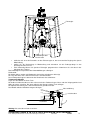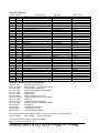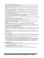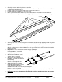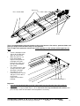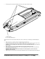
1
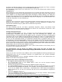
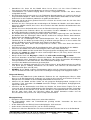
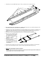
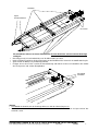
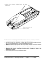
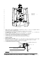
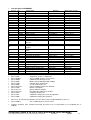
Bauanleitung für das Modell Powercat, Best.-Nr.: 2125
Beschreibung des Originals
Class 1 Offshore Rennkatamarane sind Boote mit einer länge von 12-14m. Sie erreichen
Endgeschwindigkeiten
von
250
km/h
und
mehr.
Aus dem maximal zulässigen 8,2 Litern Hubraum werden ca. 750 - 950 PS mobilisiert.
Seit Beginn der Saison 2003 kommen ausschließlich V 12 Benzinmotoren der Firma Lamborghini zum
Einsatz.
Die Besatzung eines Class 1 Bootes besteht aus dem Fahrer und dem sog. Throttleman.
Das Modell entstand in Anlehnung der berühmten Class 1Powerboote.
Ähnlich der Formel 1 Szene werden jedes Jahr rund um den Erdball verschiedene Rennen ausgetragen.
Beschreibung des Modells
Dieses Modell ist für den Einsteiger und den Fortgeschrittenen geeignet. Es wurde bei der Konstruktion
besonders auf einfache Bauweise und hohe Festigkeit geachtet.
Der Bau erfordert wenig modellbauerische Kenntnisse. Alle Teile sind passgenau lasergeschnitten und die
Tiefziehteile gefräst, sodass kaum Nacharbeit entsteht.
Der Antrieb erfolgt mit einem Mittelantrieb oder nach eigenem Ermessen mit 2 Antrieben in den
Schwimmern.
Geeignet sind Bürsten-oder bürstenlose Motoren.
Technische Daten
Länge Rumpf ca.
Länge ü.a.
ca.
Breite ca.
Höhe o.Ruder ca.
Gesamtgewicht mit RC ca.
Maßstab ca.
785 mm
895 mm
240 mm
160 mm
2,0 - 2,2 kg je nach Motor und Akku
1:12
Herstellererklärung der Fa. Graupner GmbH & Co KG
Inhalt der Herstellererklärung
Sollten sich Mängel an Material oder Verarbeitung an einem von uns in der Bundesrepublik Deutschland
vertriebenen, durch einen Verbraucher (§ 13 BGB) erworbenen Gegenstand zeigen, übernehmen wir, die
Fa. Graupner GmbH & Co KG, Kirchheim/Teck im nachstehenden Umfang die Mängelbeseitigung für den
Gegenstand.
Rechte aus dieser Herstellererklärung kann der Verbraucher nicht geltend machen, wenn die
Beeinträchtigung der Brauchbarkeit des Gegenstandes auf natürlicher Abnutzung, Einsatz unter
Wettbewerbsbedingungen, unsachgemäßer Verwendung (einschließlich Einbau) oder Einwirkung von
außen beruht.
Diese Herstellererklärung lässt die gesetzlichen oder vertraglich eingeräumten Mängelansprüche und
-rechte des Verbrauchers aus dem Kaufvertrag gegenüber seinem Verkäufer (Händler) unberührt.
Umfang der Garantieleistung
Im Garantiefall leisten wir nach unserer Wahl Reparatur oder Ersatz der mangelbehafteten Ware.
Weitergehende Ansprüche, insbesondere Ansprüche auf Erstattung von Kosten im Zusammenhang mit
dem Mangel (z.B. Ein-/Ausbaukosten) und der Ersatz von Folgeschäden sind – soweit gesetzlich
zugelassen – ausgeschlossen. Ansprüche aus gesetzlichen Regelungen, insbesondere nach dem
Produkthaftungsgesetz, werden hierdurch nicht berührt.
Voraussetzung der Garantieleistung
Der Käufer hat den Garantieanspruch schriftlich unter Beifügung des Originals des Kaufbelegs (z.B.
Rechnung, Quittung, Lieferschein) und dieser Garantiekarte geltend zu machen. Er hat zudem die defekte
Ware auf seine Kosten an die folgende Adresse einzusenden.
Fa. Graupner GmbH & CO KG, Serviceabteilung,
Henriettenstr.94 -96, D 73230 Kirchheim/Teck
GRAUPNER GmbH & Co. KG D-73230 KIRCHHEIM/TECK GERMANY
Keine Haftung für Druckfehler. Technische Änderungen vorbehalten!
#0059939
04/2008
1
Der Käufer soll dabei den Material- oder Verarbeitungsfehler oder die Symptome des Fehlers so konkret
benennen, dass eine Überprüfung unserer Garantiepflicht möglich wird.
Der Transport des Gegenstandes vom Verbraucher zu uns als auch der Rücktransport erfolgt auf Gefahr
des Verbrauchers.
Gültigkeitsdauer
Diese Erklärung ist nur für während der Anspruchsfrist bei uns geltend gemachten Ansprüche aus dieser
Erklärung gültig. Die Anspruchsfrist beträgt 24 Monate ab Kauf des Gerätes durch den Verbraucher bei
einem Händler in der Bundesrepublik Deutschland (Kaufdatum). Werden Mängel nach Ablauf der
Anspruchsfrist angezeigt oder die zur Geltendmachung von Mängeln nach dieser Erklärung geforderten
Nachweise oder Dokumente erst nach Ablauf der Anspruchsfrist vorgelegt, so stehen dem Käufer keine
Rechte oder Ansprüche aus dieser Erklärung zu.
Verjährung
Soweit wir einen innerhalb der Anspruchsfrist ordnungsgemäß geltend gemachten Anspruch aus dieser
Erklärung nicht anerkennen, verjähren sämtliche Ansprüche aus dieser Erklärung in 6 Monaten vom
Zeitpunkt der Geltendmachung an, jedoch nicht vor Ende der Anspruchsfrist.
Anwendbares Recht
Auf diese Erklärung und die sich daraus ergebenden Ansprüche, Rechte und Pflichten findet
ausschließlich das materielle deutsche Recht ohne die Normen des Internationalen Privatrechts sowie
unter Ausschluss des UN-Kaufrechts Anwendung.
Wichtige Sicherheitshinweise
Sie haben ein Modell erworben, aus dem – zusammen mit entsprechendem geeignetem Zubehör – ein
funktionsfähiges RC-Modell fertig gestellt werden kann. Die Einhaltung der Montage- und
Betriebsanleitung im Zusammenhang mit dem Modell sowie die Installation, der Betrieb, die Verwendung
und Wartung der mit dem Modell zusammenhängenden Komponenten können von GRAUPNER nicht
überwacht werden. Daher übernimmt GRAUPNER keinerlei Haftung für Verluste, Schäden oder Kosten,
die sich aus dem fehlerhaften Betrieb, aus fehlerhaftem Verhalten bzw. in irgendeiner Weise mit dem
Vorgenannten zusammenhängend ergeben. Soweit vom Gesetzgeber nicht zwingend vorgeschrieben, ist
die Verpflichtung der Firma GRAUPNER zur Leistung von Schadensersatz, aus welchem Grund auch
immer ausgeschlossen (inkl. Personenschäden, Tod, Beschädigung von Gebäuden sowie auch Schäden
durch Umsatz- oder Geschäftsverlust, durch Geschäftsunterbrechung oder andere indirekte oder direkte
Folgeschäden), die von dem Einsatz des Modells herrühren.
Die Gesamthaftung ist unter allen Umständen und in jedem Fall beschränkt auf den Betrag, den Sie
tatsächlich für dieses Modell gezahlt haben.
Die Inbetriebnahme und der Betrieb des Modells erfolgt einzig und allein auf Gefahr des
Betreibers. Nur ein vorsichtiger und überlegter Umgang beim Betrieb schützt vor Personen- und
Sachschäden.
Prüfen Sie vor dem ersten Einsatz des Modells, ob Ihre Privat-Haftpflichtversicherung den Betrieb von
Modellschiffen dieser Art mit einschließt. Schließen Sie gegebenenfalls eine spezielle RC-ModellHaftpflichtversicherung ab.
Diese Sicherheitshinweise müssen unbedingt aufbewahrt werden und bei einem Weiterverkauf des
Modells an den Käufer weitergegeben werden.
Folgende Punkte müssen unbedingt beachtet werden:
• Das Modell ist nicht für Kinder unter 14 Jahren geeignet.
• Die hervorstehenden Teile an dem Modell können scharf sein und die Antennen können
Augenverletzungen hervorrufen.
• Beachten Sie beim Einsatz von Werkzeugen die möglichen Gefahren durch diese.
• Das Modell niemals betreiben, wenn sich Menschen und Tiere im Wasser befinden! Da, bedingt
durch die hohe Geschwindigkeit des Modells, eine erhebliche Verletzungsgefahr für diese besteht.
• Lassen Sie Ihr Modell nicht in Naturschutz-, Landschaftsschutz-, oder Gewässerschutzgebieten
fahren. Informieren Sie sich bei Ihrer Gemeinde über die für den Schiffsmodellbau freigegebenen
Gewässer.
• Fahren Sie niemals im Salzwasser.
• Fahren Sie niemals bei widrigen Witterungsbedingungen, wie z.B. Regen, Gewitter, stärkerem Wind
sowie höherem Wellengang, Strömung des Gewässers usw.
• Beachten Sie die Empfehlungen und Hinweise zu Ihrer Fernsteuerung und Zubehörteilen.
GRAUPNER GmbH & Co. KG D-73230 KIRCHHEIM/TECK GERMANY
Keine Haftung für Druckfehler. Technische Änderungen vorbehalten!
#0059939
04/2008
2
•
•
•
•
•
•
•
•
•
•
•
•
•
•
•
•
•
•
•
Kontrollieren Sie, bevor Sie das Modell fahren lassen, dieses auf eine sichere Funktion der
Fernsteuerung sowie die Steckverbindungen auf sichere und feste Verbindung.
Trockenbatterien zur Stromversorgung dürfen niemals nachgeladen werden. Nur Akkus dürfen
nachgeladen werden.
Die Reichweite der Fernsteuerung muss vor Fahrtbeginn überprüft worden sein. Laufen Sie hierzu mit
eingeschaltetem Modell ca. 100 m vom Sender weg, ein Helfer bedient währenddessen den Sender.
Hierbei müssen alle Funktionen problemlos ausgeführt werden können.
Prüfen Sie, ob der von Ihnen genutzte Kanal frei ist. Fahren Sie niemals, wenn Sie sich nicht sicher
sind, ob der Kanal frei ist.
Beachten Sie, dass Funkgeräte oder Sendeanlagen die Funktion des Modells stark stören können.
Achten Sie möglichst darauf, dass keines dieser Geräte in der Nähe betrieben wird während Sie das
Modell betreiben.
Arbeiten Sie nur an den Antriebsteilen, wenn der Fahrakku nicht angeschlossen ist.
Bei angeschlossenem Fahrakku dürfen Sie und andere Personen niemals in den Bereich der
drehenden Antriebsteile, besonders der Schiffsschrauben, kommen.
Die empfohlene Betriebsspannung nicht übersteigen. Eine höhere Spannung kann zum Überhitzen
der Motoren bzw. des Fahrtreglers führen oder die elektrischen Leitungen können durchschmoren.
Dadurch kann das Modell zerstört werden.
Achten Sie auf Leichtläufigkeit aller Antriebskomponenten. Dies gilt besonders während des
Fahrbetriebs, da sich Blätter und andere Dinge im Antrieb verfangen können. In einem solchen Fall
können die Motoren bzw. der Fahrtregler durch Überlast zerstört werden.
Die Batterie und Akkus dürfen nicht kurzgeschlossen werden, sowie nicht direkt dem Wasser
ausgesetzt werden.
Entnehmen Sie den Fahrakku und die Senderbatterien bzw. -akkus bei Nichtgebrauch des Modells.
Setzen Sie das Modell nicht starker Luftfeuchtigkeit, Hitze, Kälte sowie Schmutz aus.
Sichern Sie das Modell und den Sender beim Transport gegen Beschädigung sowie Verrutschen.
Betreiben Sie niemals das Modell an einem stark bewegten Wasser (z.B. Fluss), da bei einem evtl.
Defekt das Modell abtreiben kann.
Bringen Sie bei einer evtl. Bergung des Modells sich nicht selbst sowie andere in Gefahr.
Achten Sie besonders auf die Wasserdichtheit des Modells. Ein Modellboot wird bei entsprechendem
Wassereinbruch sinken. Kontrollieren Sie das Modell vor jeder Fahrt, ob irgendeine Beschädigung
vorliegt und ob Wasser durch die Antriebs- bzw. Ruderwellen eindringen kann.
Lassen Sie das Modell nach Gebrauch gut austrocknen.
Kontrollieren Sie unbedingt während der ersten Fahrt mehrmals, ob die Wellenanlagen wasserdicht
sind. Wenn Wasser eindringt, demontieren Sie die Wellen und schmieren die Stevenrohre mit
ausreichend Fett (Best.-Nr. 570) nach.
HINWEIS: die im Modell verbauten Elektromotoren dürfen nicht im Hausmüll entsorgt werden, sie
müssen demontiert werden und separat an der zuständigen Entsorgungsstelle abgegeben werden.
Pflege und Wartung
•
•
•
Säubern Sie das Modell nach jedem Gebrauch. Entfernen Sie evtl. eingedrungenes Wasser. Sollte
Wasser in die RC-Komponenten gedrungen sein, legen Sie diese trocken und schicken Sie die RCKomponenten zur Kontrolle an die zuständige GRAUPNER Servicestelle ein.
Säubern Sie das Modell und den Sender nur mit geeigneten Reinigungsmitteln. Geeignet ist ein
fusselfreies Tuch. Verwenden Sie niemals chemische Reiniger, Lösungsmittel, Reinigungsbenzin,
Spiritus oder ähnliches.
Schmieren Sie die Antriebswellen nach Ende des Betriebs mit einem kleinen Tropfen Öl an den
Lagern ab. Auch die äußeren Wellenlager bei den Propellern müssen geschmiert werden. Verwenden
Sie zum Schmieren der Antriebe nur Öl, welches das Wasser nicht gefährdet bzw. verschmutzt (z.B.
Best.-Nr. 206). Nach Ende der Fahrsaison sollten die Wellen demontiert werden und mit
wasserneutralem Fett (z.B. Best.-Nr. 570) neu abgeschmiert werden.
Montageanleitung
• Überprüfen Sie den Inhalt des Baukastens anhand der Stückliste.
• Alle Kunststoffteile sollten von Trennmittelresten gereinigt werden. Verwenden Sie dazu eine
Spülmittellösung.
• An den Klebestellen das ABS mit feinem Schmirgelpapier leicht aufrauen.
• Stellen Sie das Unterwasserteil (Teil 1) auf eine ebene Unterlage.
• Zeichnen Sie mit einem Bleistift eine Linie 2 mm unterhalb der Fräskante von innen an die Bordwand.
GRAUPNER GmbH & Co. KG D-73230 KIRCHHEIM/TECK GERMANY
Keine Haftung für Druckfehler. Technische Änderungen vorbehalten!
#0059939
04/2008
3
• Schneiden Sie von dem ABS Profil 3x3mm (Teil 2) 12 Stücken von ca. 20mm Länge ab.
3
2
1
• Diese Stücke kleben Sie im Abstand von ca. 120mm (von hinten gemessen) unterhalb entlang der Linie
Verwenden Sie UHU-Plast spezial oder Sekundenkleber.
• Entnehmen Sie der 4mm Sperrholzplatte die Heckverstärkung (Teil 3) streichen es mehrmals mit
Glattfix (Best. 207) und kleben Sie es von innen gegen den Spiegel (Stabilit oder Sekundenkleber).
• Wichtig: Die Bohrungen und Schlitze dürfen nicht mit Klebstoff verschlossen werden
• Lösen Sie aus der 1mm Sperrholzplatte die Teile 4, 5 und 6 und entfernen eventuelle Grate.
• Kleben Sie den Schwimmerspant
(Teil 4) von unten in die Schlitze
des Horizontalspanten (Teil 6).
• Teil 5 kleben Sie von oben in die
hinteren
Schlitze
des
Horizontalspanten.
• Achtung die Spanten senkrecht
zum Teil 6 aufkleben
• Ist das Gerippe getrocknet, mit
Porenfüller mehrmals streichen,
um die Sperrholzeile wasserfest
zu bekommen.
6
5
4
• Die beiden hinteren Zapfen von Teil 6 stecken Sie bis zum Anschlag in die Schlitze des Heckspiegels.
• Legen Sie den Horizontalspant auf die seitlich im Rumpf angeklebten ABS-Profile (Teile 2).
• Wichtig: Das Spantgerippe verzugfrei einkleben!
Dazu das Bootsunterteil mit den Schwimmern auf eine ebene Fläche legen und in das Boot ein
Gewicht legen, um es in dieser Position zu halten!
GRAUPNER GmbH & Co. KG D-73230 KIRCHHEIM/TECK GERMANY
Keine Haftung für Druckfehler. Technische Änderungen vorbehalten!
#0059939
04/2008
4
verkleben
Spant
herunterdrücken
einstecken
•
•
•
•
Die Schwimmer müssen an den 6 Abreißkanten bis zum Aushärten auf einer ebenen Unterlage
aufliegen!
Den Ringspant (6) mit Sekundenkleber auf die ABS Profile (2) heften.
Nach Aushärtung verkleben Sie den Ringspant mit der Bordwand des Unterteils mit Stabilit oder Acrylit.
Spant 4 wird am Boden nur punktförmig verklebt.
Fertigen Sie aus den Teilen 7 und 8 die Servohalterung und kleben Sie diese mit Stabilit in dem Schlitz
des Heckspantes und auf den Rumpfboden.
3
mit Stabilit
verkleben
7
8
Wichtig
• Das Modell mit Gewicht auf der Unterlage belassen und das Oberteil anpassen.
• Zuerst den vorderen Bereich vom Ober- und Unterteil mit Stabilit einstreichen und passend auf das
Unterteil setzen.
GRAUPNER GmbH & Co. KG D-73230 KIRCHHEIM/TECK GERMANY
Keine Haftung für Druckfehler. Technische Änderungen vorbehalten!
#0059939
04/2008
5
• Sichern Sie das Oberteil auf dem Unterteil mit einigen
Klebestreifen.
9
Zuerst diesen Bereich mit
Stabilit verkleben
Die Klebestreifen nur am Heckspiegel und den vorderen Mittelteil verwenden, um Verzug zu vermeiden.
•
•
•
•
•
•
•
Ist der Klebstoff ausgehärtet, das Gewicht entnehmen und das Boot umdrehen.
Die Klebestreifen am Heck entfernen und die mittlere Fläche im Heckbereich mit Stabilit bestreichen,
und an den Heckspiegel drücken, bis zum Aushärten mit Klebestreifen sichern.
Wichtig: Zum Aushärten des Klebers das Modell wieder mit den Gleitkufen auf die ebene Unterlage
stellen und mit dem Gewicht belasten.
Nach dem Aushärten des Klebstoffes drehen Sie das Boot um (auf das Deck legen).
Jetzt wird die Sicke der Oberschale rings um das Boot mit dickflüssigem Sekundenkleber oder UHUPlast spezial verklebt.
Wichtig! bei den seitlichen Verklebungen keine Klebestreifen verwenden, um Beulen in der
Rumpfseite zu vermeiden.
Nach Aushärtung die Spalten ringsum mit Klebstoff auffüllen.
GRAUPNER GmbH & Co. KG D-73230 KIRCHHEIM/TECK GERMANY
Keine Haftung für Druckfehler. Technische Änderungen vorbehalten!
#0059939
04/2008
6
2. dann diesen Bereich
mit Stabilit verkleben
3. mit Sekundenkleber dickflüssig
oder
UHU-plast-spezial verkleben,
nach Aushärtung mit Klebstoff
auffüllen
Wichtig
keine Klebestreifen verwenden
•
•
•
•
•
•
•
•
aufbohren (7mm)
Nach dem Aushärten des Klebers drehen Sie das Modell um und verkleben Sie die Oberschale mit dem
Unterteil von innen, indem Sie den Klebstoff entlang der Rille oberhalb des Ringspantes laufen lassen.
Bohren Sie die beiden 7mm Löcher des Spant 3 durch die Heckflächen.
Um das Abrisskanten des Rumpfes zu
schärfen und die Geschwindigkeit,
sowie die Stabilität des Bootes zu
erhöhen, können von unten die
Laufflächen 18 mit Sekundenkleber
aufgeklebt werden.
Die
seitlichen
Spalten
können
verspachtelt werden, ist aber nicht
notwendig.
Bauen Sie nun aus den 4mm
Laserteilen
den
Bootsständer
entsprechend
der
Zeichnung
zusammen.
Lackieren Sie den Ständer mehrmals
mit Glattfix (Best.Nr. 207), um den
Ständer wasserfest zu machen.
Kleben
Sie
mit
Kontaktkleber
(Best.Nr.1096) auf die Bootsauflage je ein
aufgeschlitztes
Stück
Silikonschlauch,
um
Beschädigungen des Modells zu vermeiden.
Nach der Aushärtung können Sie das Modell auf
dem Ständer abstellen.
15
12
14
11
10
13
GRAUPNER GmbH & Co. KG D-73230 KIRCHHEIM/TECK GERMANY
Keine Haftung für Druckfehler. Technische Änderungen vorbehalten!
#0059939
04/2008
7
•
•
•
•
•
•
•
•
•
•
•
•
•
Kleben
Sie
die
beiden
Sperrholzunterlagen 16 des
Motorträgers im Abstand von
190mm mit Stabilit auf die
Mittelfläche des Rumpfes.
0
19
Bohren Sie im Abstand von
5
13
105 und 135 mm von der
Hinterkante je ein 4-5mm
5
10
Loch genau in den Mittelknick
durch
den
Rumpfboden.
Schneiden Sie mit einem
Cuttermesser
den
Steg
zwischen den Bohrungen
heraus.
Vorsicht!
Abrutschgefahr Nicht zu
19
sehr aufdrücken, Lieber
16
mehrmals schneiden.
Schrauben Sie nun die
Ruderanlage mittig an das
18
Heck des Rumpfes.
17
Schieben Sie die Flexwelle
durch den Strut und das
gebohrte Loch im Bootsboden
31
Löten Sie an den Motor den Entstörkondensator
30
(31) über beide Anschlussfahnen und die
32
Motoranschlußkabel (32) an.
Von dem Motorträger (19) sägen sie das
überstehende Teil ab.
Schrauben Sie den Motor an den Träger.
Schrauben Sie die Kupplung auf die Motorwelle.
Stecken Sie die Kupplung mit Motor auf die
Flexwelle. Den vorbereiteten Sperrholzträger
schieben Sie zwischen die Sperrholzunterlagen
(16) und den Kunststoffmotorträger (19). Durch
Abschleifen passen Sie den Sperrholzträger an die
19
Unterlagen an.
absägen
Wichtig! Die Flexwelle darf keinen Knick
bekommen. Sie sollte einen leichten Bogen vom Strut zur Motorkupplung beschreiben. Das
Langloch im Bootsboden muss eventuell nachgearbeitet werden.
Den Motorträger kleben Sie, wenn alles passt, mit Stabilit auf die Unterlagen.
Ist der Klebstoff getrocknet ziehen Sie die Flexwelle heraus und schieben über das Teflonrohr das
Alu-Schutzrohr und montieren das Teflonrohr vom Strut ins Bootsinnere. Erweitern Sie jetzt das
Langloch im Boden bis das Alurohr, ohne die Welle zu biegen, durchpasst.
Verschrauben Sie die Flexwelle mit der Motorkupplung und verkleben Sie das Alu-Schutzrohr mit
Stabilit im Bootsboden von innen und außen. Die Flexwelle sollte sich leicht drehen.
auf 2mm für
Gestängeanschluss
aufbohren
•
24
23
Die Löcher im
Lenkhebel des Ruders auf 2mm aufbohren und den
Gestängeanschluss montieren, er muss im Ruderhebel
drehbar sein.
20
21
22
GRAUPNER GmbH & Co. KG D-73230 KIRCHHEIM/TECK GERMANY
Keine Haftung für Druckfehler. Technische Änderungen vorbehalten!
#0059939
04/2008
8
Montieren Sie die dem Servo mitgelieferten Gummilager und stecken Sie von unten die
Messinghülsen in die Öffnungen der Gummilager.
TIPP: Stecken Sie die Messinghülsen zum Montieren auf einen passenden Schraubendreher.
• Schrauben Sie den Servo in den Servohalter gemäß den Zeichnungen.
• Aus der Tiefziehplatte den Lufteinlass 26 ausschneiden. Die Schneidelinie ist auf der Innenseite mit
einer Wulst markiert. Die Schnittkante gerade verschleifen und an die Vorderkante des Luftrohres
ankleben. Den Lufteinlass nicht durchbohren oder öffnen.
Das kann beim Umschlagen des Bootes zum Wassereinbruch und damit zum Untergang führen.
• Es sind zwei verschiedene Lufthutzen im Bausatz enthalten.
Je nachdem, welches Bootsdesign man nachbauen möchte, können die Lufthutzen 27 oder 28
ausgewählt werden.
• Die Teile werden ebenfalls an der inneren Wulst als Markierung ausgeschnitten, plan geschliffen und
die Hälften miteinander verklebt.
• Verwenden Sie Stabilit, Acrylit oder UHU plast spezial. Nach dem Trocknen die Klebenaht von
außen verspachteln und schleifen. Kleben Sie die Lufthutzen auf die Ansatzstutzen, ohne diese zu
öffnen.
• Die Auspuffrohre 29 mittig teilen von hinten stumpf an die Lüftersockel kleben ohne diese zu öffnen.
•
28
29
27
26
25
•
•
•
•
•
•
•
•
•
•
•
•
•
•
•
•
•
Lackierung.
Verschleifen Sie alle Klebenähte, evtl. verspachteln. Ritzen können mit UHU-plast-spezial aufgefüllt
werden.
Nach dem Bearbeiten der Klebenähte und Ritzen schleifen Sie das Boot und den Deckel komplett
zuerst mit 400er bis 600er Schleifpapier oder Schleifvlies mit leichten kreisenden Bewegungen.
Waschen Sie dann vom Boot den Schleifstaub und das Trennmittel mit einer Spülmittellösung ab.
Lackieren Sie das Boot am Besten mit Sprühfarben oder Airbrush.
Durch die großen glatten Flächen ist das Modell hervorragend für Airbrushbilder geeignet.
Die optimalen Farben erfragen Sie bitte im Modellbau- oder Farb-Fachhandel. Wählen sie ein
Farbsystem, welches auf ABS-Kunststoff sicher hält. Mischen Sie nicht die einzelnen Farbsysteme
(Hersteller) untereinander.
Nitrofarben sind nicht zu empfehlen, da diese den Kunststoff anlösen.
Nach dem Trocknen der Farbe montieren sie wieder die Ruderanlage, Welle und den Motor
Kleben Sie die Gummitüllen mit Sekundenkleber wasserdicht in die 7mm Löcher des Heckspiegels
Schrauben sie die Gabelköpfe auf die Rudergestänge.
Fetten oder ölen Sie die Rudergestänge leicht ein und stecken Sie diese von innen durch die
Gummitüllen
Klicken Sie die Gabelköpfe im Servoarm in das äußere Loch. Stecken Sie die Rudergestänge durch
die Gummimanschette.
Kleben Sie den Empfänger mit Klettband rechts neben die Servohalterung
Schließen Sie den Servo an den Empfänger an.
Schließen Sie den Fahrtenregler an den Empfänger an.
Schalten Sie den Sender ein und bringen alle Trimm- und Steuerhebel in Neutralstellung
GRAUPNER GmbH & Co. KG D-73230 KIRCHHEIM/TECK GERMANY
Keine Haftung für Druckfehler. Technische Änderungen vorbehalten!
#0059939
04/2008
9
Fahrtregler
Verbindungskabel
Best.Nr 3031
Schließen Sie einen der Fahrakkus an den Fahrtenregler an, der Servo und der Regler gehen jetzt in
Mittelstellung
• Stellen Sie die Ruderanlage in Mittelstellung und Schrauben Sie die Rudergestänge in den
Gestängeanschlüssen fest.
• Falls notwendig, können Sie jetzt den Fahrregler programmieren. Informieren Sie sich dazu in der
Anleitung Ihres Reglers.
Den Dekorbogen entsprechend der Kartonabbildungen aufbringen.
Fahrbetrieb:
Die beiden Akkus werden mit Klettband in den beiden Schwimmern befestigt.
Die Lage der Akkus muss durch Fahrversuche ermittelt werden.
Der Schwerpunkt liegt bei 165mm vor der Hinterkante der Schwimmer.
Trimmen des Modells
Legen Sie das Modell auf einen Tisch
Die beiden Schlitzschrauben auf der rechten Seite des Ruderauslegers lösen und den Neigungswinkel und
Höhe des Struts einstellen. Der Strut sollte wie der Rumpf auf dem Tisch aufliegen
Die optimale Einstellung muss durch Probefahrten gefunden werden.
Das Modell sollte bei Gleitfahrt waagerecht liegen.
Wasserkühlung
•
Schrauben
Tischkante
Wichtig: Die Schrauben wieder festziehen.
GRAUPNER GmbH & Co. KG D-73230 KIRCHHEIM/TECK GERMANY
Keine Haftung für Druckfehler. Technische Änderungen vorbehalten!
#0059939
04/2008
10
Stückliste Powercat
Teil Nr. Anzahl
Bezeichnung
1
1
Bootsunterteil
2
0.5m
ABS Vierkantprofil
3
1
Heckverstärkung
4
1
Spant für Schwimmer
5
1
Decksspant
6
1
Horizontalspant
7
1
Servohalterung oben
8
2
Servohalterung Seite
9
1
Bootsoberteil
10
2
Ständerstrebe Seite
11
1
Ständerstrebe oben
12
2
Keile
13
2
Träger
14
0,25m Silikonschlauch
15
6
Gleitflächen
16
2
Unterlage für Motorträger
17
1
Motorträgerhalter vorn
18
2
Motorträgerhalter seitlich
19
1
Motorträger
20
1
Ruderanlage mit Strut
21
1
Flexwelle mit Teflonrohr
22
1
Schutzrohr
23
2
Gummimanschette
24
2
Gestängeanschluss
25
2
Deckel
26
2
Lufteinlass vorn
27
2
Lufteinlass gebogen (zweiteilig)
28
2
Lufteinlass (zweiteilig)
29
1
Auspuffrohre
30
1
Motor Speed 700
31
1
Kondensator
32
1
Kabel 2,5mm²
33
1
Stecker + Buchse G2 1 Satz
34
1
Dekorbogen
Material
ABS Tiefziehteil
ABS Profil
Sperrholz 4mm
Sperrholz 1mm
Sperrholz 1mm
Sperrholz 1mm
Sperrholz 4mm
Sperrholz 4mm
ABS Tiefziehteil
Sperrholz 4mm
Sperrholz 4mm
Sperrholz 4mm
Sperrholz 4mm
5x7x1mm
1,0mm ABS
Sperrholz 1mm
Sperrholz 4mm
Sperrholz 4mm
Fertigteil
Fertigteil
Fertigteil
Alurohr
Fertigteil
Fertigteil
ABS Tiefziehteil
ABS Tiefziehteil
ABS Tiefziehteil
ABS Tiefziehteil
Alurohr
Fertigteil
Fertigteil
Fertigteil
Fertigteil
Fertigteil
Abmessung
1,5mm ABS
3 x 3 x 500mm
Laserteil
Laserteil
Laserteil
Laserteil
Laserteil
Laserteil
1,0mm ABS
Laserteil
Laserteil
Laserteil
Laserteil
Fertigteil
Laserteil
Laserteil
Laserteil
Laserteil
1157.2
Fertigteil Best.Nr.3341
Fertigteil Best.Nr.3364
7x6x55
Fertigteil Best.Nr.3356
Fertigteil Best.Nr.3364
1,0mm ABS
1,0mm ABS
1,0mm ABS
1,0mm ABS
7x6x40
Nicht im Lieferumfang
Nicht im Lieferumfang
Nicht im Lieferumfang
Nicht im Lieferumfang
Benötigtes Zubehör, nicht im Lieferumfang
Best.-Nr. 2847
Fahrtregler Power V 60
Best.-Nr. 2490.6
Akku 6/3600
(2 Stück erforderlich)
Best.-Nr. 3031
Akkuverbindungskabel G2
Best.-Nr. 6306
Motor Speed 700 BB Turbo Neodym
Best.-Nr. 3588
Kondensator
Best.-Nr. 3389
Kabel 2,5mm²
Best.Nr. 2989
Stecker + Buchse G2 1 Satz
Best.Nr. 2318.45
Carbon Hydropropeller K-Serie 45mm
Best.-Nr. 3368
Klettband
Best.-Nr.531.19
flexibles Klebeband Cellpack
Best.-Nr. 4729
FM-Fernlenksystem ab X 408, 40Mhz
Best.Nr. 6414
Ultramat 14
Best.Nr.3011
Ladekabel für Fahrakku
Best.Nr.3022
Ladekabel für Sender
Best.Nr.3374
Kupplungsbuchse 4/5mm
Zur Steigerung der Geschwindigkeit können auch 7 zellige Akkus verwendet werden.
Best.Nr. 2490.7
Akku 7/3600
(2 stück erforderlich)
Viel Spaß beim Bau und beim Fahren des Modells
Wünscht ihnen das Graupner Team
GRAUPNER GmbH & Co. KG D-73230 KIRCHHEIM/TECK GERMANY
Keine Haftung für Druckfehler. Technische Änderungen vorbehalten!
#0059939
04/2008
11
Building instructions for the Powercat model boat, Order No.: 2125
The full-size vessel
Class 1 off-shore catamarans are racing boats with a hull length of 12 to 14 m, and are capable of top
speeds around 250 km / hr or more. The maximum permissible engine capacity is 8.2 litres, and the power
plants are rated at around 750 to 950 BHP. Since the start of the 2003 season all the boats have been
powered by Lamborghini V12 petrol engines.
The crew of a Class 1 boat consists of the driver and the ‘throttleman’.
The design of our model is based on these famous Class 1 power boats.
Every year these vessels take part in a series of races held all round the globe, in a similar style to the
Formula 1 car-racing scene.
The model
This boat is suitable for beginner and advanced modeller alike. At the design stage we paid particular
attention to simple construction and good structural strength.
Building the model calls for little in the way of modelling knowledge. All the components are accurately lasercut, and the vacuum-moulded parts are machine-trimmed, with the result that hardly any trimming or
adjustment is required.
The boat is designed for a standard power system consisting of a single central electric motor; at the
builder’s discretion two motors can be installed in the sponsons.
The model can be fitted with brushed or brushless motors.
Specification
Hull length approx.
Overall length approx.
Beam approx.
Height excl. rudder approx.
All-up weight including RC approx.
Scale approx.
785 mm
895 mm
240 mm
160 mm
2.0 to 2.2 kg, according to motor and battery
1 : 12
Manufacturer’s declaration from Graupner GmbH & Co KG
Contents of the manufacturer’s declaration:
If material defects or manufacturing faults should arise in a product distributed by us in the Federal Republic
of Germany and purchased by a consumer (§ 13 BGB), we, Graupner GmbH & Co. KG, D-73230
Kirchheim/Teck, Germany, acknowledge the obligation to correct those defects within the limitations
described below.
The consumer is not entitled to exploit this manufacturer’s declaration if the failure in the usability of the
product is due to natural wear, use under competition conditions, incompetent or improper use (including
incorrect installation) or external influences.
This manufacturer’s declaration does not affect the consumer’s legal or contractual rights regarding defects
arising from the purchase contract between the consumer and the vendor (dealer).
Extent of the guarantee
If a claim is made under guarantee, we undertake at our discretion to repair or replace the defective goods.
We will not consider supplementary claims, especially for reimbursement of costs relating to the defect (e.g.
installation / removal costs) and compensation for consequent damages unless they are allowed by statute.
This does not affect claims based on legal regulations, especially according to product liability law.
Guarantee requirements
The purchaser is required to make the guarantee claim in writing, and must enclose original proof of
purchase (e.g. invoice, receipt, delivery note) and this guarantee card. He must send the defective goods to
us at his own cost, using the following address:
Graupner GmbH & Co. KG, Service Department,
Henriettenstr. 94 - 96, D-73230 Kirchheim/Teck, Germany
GRAUPNER GmbH & Co. KG D-73230 KIRCHHEIM/TECK GERMANY
Keine Haftung für Druckfehler. Technische Änderungen vorbehalten!
#0059939
04/2008
12
The purchaser should state the material defect or manufacturing fault, or the symptoms of the fault, in as
accurate a manner as possible, so that we can check if our guarantee obligation is applicable.
The goods are transported from the consumer to us and from us to the consumer at the risk of the
consumer.
Duration of validity
This declaration only applies to claims made to us during the claim period as stated in this declaration. The
claim period is 24 months from the date of purchase of the product by the consumer from a dealer in the
Federal Republic of Germany (date of purchase). If a defect arises after the end of the claim period, or if the
evidence or documents required according to this declaration in order to make the claim valid are not
presented until after this period, then the consumer forfeits any rights or claims from this declaration.
Limitation by lapse of time
If we do not acknowledge the validity of a claim based on this declaration within the claim period, all claims
based on this declaration are barred by the statute of limitations after six months from the time of
implementation; however, this cannot occur before the end of the claim period.
Applicable law
This declaration, and the claims, rights and obligations arising from it, are based exclusively on the pertinent
German Law, without the norms of international private law, and excluding UN retail law.
Important safety notes
You have acquired a kit which can be assembled into a fully working RC model when fitted out with suitable
accessories. However, we as manufacturers have no control over the way you build and operate your RC
model boat, nor how you install, operate and maintain the associated components, and for this reason we
are obliged to deny all liability for loss, damage or costs which are incurred due to the incompetent or
incorrect use and operation of our products, or which are connected with such operation in any way. Unless
otherwise prescribed by binding law, the obligation of the GRAUPNER company to pay compensation,
regardless of the legal argument employed, is excluded. This includes personal injury, death, damage to
buildings, damage due to loss of business or turnover, interruption of business or other direct or indirect
consequent damage whose root cause was the operation of the model.
The total liability in all cases is limited to the amount of money which you actually paid for this model.
This model boat is built and operated at the sole and express responsibility of the operator. The only
way to avoid injury to persons and damage to property is to handle and operate the model with the
greatest care and consideration at all times.
Before you run the model for the first time please check that your private third-party insurance covers the
operation of model boats of this kind. If in doubt, take out a special insurance policy designed to cover
modelling risks.
These safety notes should be kept in a safe place. If you ever dispose of the model, be sure to pass them on
to the new owner.
The following points are important and must be observed at all times:
• This model is not suitable for young persons under 14 years of age.
• The projecting parts of the model may be sharp, and the aerials could cause eye injuries.
• Bear in mind that tools can be dangerous; always be careful when handling them.
• Never operate the model when there are persons or animals in the water, as its high speed constitutes a
considerable injury hazard.
• Do not run your model in protected sites, animal or plant sanctuaries or sites of special scientific interest
(SSSIs). Check with your local authority that the stretch of water you wish to use is suitable for model
boats.
• Never run the boat in salt water.
• Never run the boat in adverse conditions, e.g. rain, storm, strong wind, choppy water or strong currents.
• Read the instructions provided with your radio control system and accessories, and observe the
recommendations.
• Before you run the model check that the radio control system is working reliably, and that all connections
are secure.
• Dry batteries must never be recharged. Only batteries marked as “rechargeable” are safe to recharge.
• Check the range of the radio control system before each session: ask a friend to walk about 100 m away
from the model carrying the transmitter. Your assistant will be able to tell you whether all the working
GRAUPNER GmbH & Co. KG D-73230 KIRCHHEIM/TECK GERMANY
Keine Haftung für Druckfehler. Technische Änderungen vorbehalten!
#0059939
04/2008
13
•
•
•
•
•
•
•
•
•
•
•
•
•
•
•
•
functions operate correctly at this range.
Ensure that the frequency you intend to use is not already in use by other modellers. Never run your
boat if you are not certain that your channel is free.
Bear in mind that other radio equipment and transmitting stations can cause serious interference to the
model. Ensure that no equipment of this type is being used in the vicinity while you are operating the
model.
Do not carry out any work on the drive train unless you have disconnected and removed the battery.
When the drive batteries are connected, keep well clear of the area around the propellers, and make
sure any spectators do the same.
Do not be tempted to exceed the recommended operating voltage. Higher voltages may cause the
motors or speed controller to overheat, and the electrical cables may even melt. If this should happen,
the model could easily be ruined.
Check that all the drive train components work smoothly and freely. This applies in particular when the
boat is running, as leaves and other debris may get caught in the power system components. The
motors and speed controller could then be ruined by overloading.
Dry cells and rechargeable batteries must never be short-circuited. Do not allow them to come into direct
contact with water.
Remove the rechargeable battery and the dry cells in the transmitter and receiver pack if the model is to
be transported, or will not be used for a long period.
Do not subject the model boat to high levels of humidity, heat, cold or dirt.
Secure the model and your RC equipment carefully when transporting them. They may be seriously
damaged if they are free to slide about.
Never operate the boat in moving water (e.g. a river), as the model could drift off downstream if a fault
should occur.
If you have to salvage the model, take care not to risk your own life or that of others.
Take particular care to ensure that the boat is completely watertight, as it will sink if too much water
enters the hull. Check the model for damage before every run, and ensure that water cannot penetrate
through the shaft bearings or the rudder bushes.
Allow the boat to dry out thoroughly after each session.
Be sure to check repeatedly during the first run that the shaft systems are watertight. If water enters the
hull through the shaft tubes, remove the shafts and lubricate the tubes with plenty of grease, Order No.
570.
NOTE: it is important not to dispose of the electric motors installed in the model in the ordinary
household waste. They must be removed from the boat and taken to the appropriate collection point for
electrical waste.
Care and maintenance
• Clean the model carefully after every run, and remove any water which penetrates the hull. If water gets
into the RC components, dry them out carefully and send them to your nearest GRAUPNER Service
Centre for checking.
• Clean the model and transmitter using suitable cleaning agents only. All you need is a lint-free cloth.
Never use chemical cleaners, solvents, methylated spirits, white spirit or similar.
• Lubricate the propeller shafts at regular intervals by applying a small drop of oil to the bearings. The
external shaft bearings adjacent to the propellers must also be lubricated. Use a type of oil which does
not soil or contaminate water, e.g. Order No. 206. At the end of the season we recommend that you
remove the propeller shafts and re-lubricate them using water-neutral grease, e.g. Order No. 570.
Assembling the model
•
Check the contents of the kit against the Parts List.
•
It is important to clean all the plastic parts to remove any traces of grease and mould release agent; use
a liquid detergent solution for this.
•
Lightly sand the joint areas of the ABS parts to roughen the surfaces.
•
Lay the bottom hull section (part 1) on a flat surface.
•
Draw a pencil-line round the inside face of the hull at a point 2 mm below the machined cut-line.
GRAUPNER GmbH & Co. KG D-73230 KIRCHHEIM/TECK GERMANY
Keine Haftung für Druckfehler. Technische Änderungen vorbehalten!
#0059939
04/2008
14
•
•
•
•
•
•
Check the contents of the kit against the Parts List.
It is important to clean all the plastic parts to remove any traces of grease and mould release agent; use
a liquid detergent solution for this.
Lightly sand the joint areas of the ABS parts to roughen the surfaces.
Lay the bottom hull section (part 1) on a flat surface.
Draw a pencil-line round the inside face of the hull at a point 3 mm below the machined cut-line.
Locate the 3 x 3 mm square-section ABS strip (part 2), and cut twelve pieces about 20 mm long from it.
2
3
1
•
•
•
•
•
•
•
•
•
•
•
Starting at the stern, glue these strips to the inside of the hull with the top edge aligned with the pencilline; space them out at intervals of about 120 mm. Use UHU-Plast Spezial or cyano-acrylate adhesive
for this.
Remove the transom reinforcement (part 3) from the 4 mm plywood sheet, apply several coats of
Glattfix (cellulose lacquer - Order No. 207) to it, then glue it to the inside of the transom using Stabilit
Express or cyano.
Important: the holes and slots must not be clogged up with glue.
Press parts 4, 5 and 6 out of the 1
mm plywood sheet, and remove
any rough edges.
6
Glue the sponson former (part 4)
in the slots in the horizontal crutch
5
(part 6) from the underside.
Glue part 5 in the rear slots in the
horizontal crutch, this time working
from the top.
Caution: take care to glue the
formers at right-angles to part 6.
Allow the glued joints to harden
thoroughly before applying several
4
coats of sanding sealer to the
wooden surfaces, to ensure that they are waterproof.
Locate the two rear lugs in part 6 and insert them in the slots in the transom reinforcement, pushing
them in as far as they will go.
Lay the horizontal crutch on the ABS strips (parts 2), which are glued to the sides of the hull.
Important: check that the wooden framework and the hull are not distorted when the parts are
joined.
GRAUPNER GmbH & Co. KG D-73230 KIRCHHEIM/TECK GERMANY
Keine Haftung für Druckfehler. Technische Änderungen vorbehalten!
#0059939
04/2008
15
Glue here
Press crutch down
Insert
This is accomplished by laying the bottom section of the boat on a flat surface, sponsons down, and
placing a weight inside the hull to keep it in this position.
The six steps of the sponsons must be left resting squarely on a flat surface until the glue has set
hard!
•
•
•
•
Tack the horizontal crutch
(part 6) to the ABS strips
(parts 2) using cyano.
When the glue has set
hard, apply Stabilit
Express or Acrylit to the
full length of the joint
between the crutch and
the sides of the bottom
hull section.
The sponson former (part
4) only needs to be spotglued to the hull floor.
Assemble the servo
mount from parts 7 and 8,
and glue it in the slots in
the transom
reinforcement and the
hull floor.
Glue with Stabilit Express
Important
•
Leave the boat weighted down on the flat surface while you check that the upper hull section fits
accurately.
•
The first step is to apply Stabilit Express to the front area of the top and bottom hull sections, then
place the top section on the bottom shell and position it accurately.
GRAUPNER GmbH & Co. KG D-73230 KIRCHHEIM/TECK GERMANY
Keine Haftung für Druckfehler. Technische Änderungen vorbehalten!
#0059939
04/2008
16
•
Fix the upper hull section to the bottom shell using a few strips of adhesive tape.
1. Start by gluing
this area with Stabilit Express
Apply the tape at the transom and the front of the centre section only (see drawing) to avoid distorting the
hull.
•
•
•
•
•
•
•
When the glue has set hard, remove the weight and turn the boat over.
Remove the strips of tape at the stern, and apply Stabilit express to the central area at the stern. Press
it against the transom, apply more adhesive tape, and leave the glued joint to set hard.
Important: place the planing steps of the boat on a flat surface and weight it down once more while the
glue is curing.
When the joints have set hard, turn the boat over again and lay it down on its deck.
Now complete the joint with the bottom hull section by applying thick cyano or UHU-Plast Spezial all
round the flange in the top shell.
Important: don’t use tape to hold the side-joints of the boat together, as this could cause
distortion in the hull sides.
Allow the glue to set hard, then check for gaps all round the hull seam and fill them with more adhesive.
GRAUPNER GmbH & Co. KG D-73230 KIRCHHEIM/TECK GERMANY
Keine Haftung für Druckfehler. Technische Änderungen vorbehalten!
#0059939
04/2008
17
2. Next glue this area with Stabilit Express
3. Apply thick cyano or UHU-Plast Spezial here,
then fill any gaps with more adhesive
Important Do not use tape!
Drill out to 7 mm Ø
•
•
•
•
•
•
•
•
When the glue has hardened fully, turn the boat over and reinforce the
joint between the top shell and the bottom section from the inside by allowing adhesive to run along the
channel above the horizontal crutch.
Continue the two 7 mm Ø holes through the transom reinforcement (part 3).
Sharpening the edges of the hull
steps increases the boat’s top speed
and stability, and this can be
achieved by gluing the planing
panels (parts 15) to the underside of
the hull using cyano.
Fitting the panels inevitably
produces gaps along the sides, and
these can be filled with filler paste if
you wish; it is not essential to do
this.
Now assemble the boatstand from
the laser-cut 4 mm plywood parts,
as shown in the drawing.
Apply several coats of Glattfix
(cellulose lacquer, Order No. 207) to
the stand to render it waterproof.
Slit the two pieces of silicone tubing (parts 14)
along their length and glue them to the support
surfaces of the boatstand using contact cement
(Order No. 1096); this avoids scratching the
boat’s surface.
Allow the boatstand to dry out thoroughly before
placing the boat in it.
15
12
14
14
12
11
10
13
GRAUPNER GmbH & Co. KG D-73230 KIRCHHEIM/TECK GERMANY
Keine Haftung für Druckfehler. Technische Änderungen vorbehalten!
#0059939
04/2008
18
•
•
•
•
•
•
•
•
•
•
•
•
•
Glue the two plywood motor mount
supports (parts 16) to the central
area of the hull, at a point 190 mm
from the transom; use Stabilit
Express for these joints.
0
19
Drill two 4 or 5 mm Ø holes in the hull
5
13
floor exactly on the central ‘V’,
located 105 mm and 135 mm from
5
10
the rear edge, then form a fore-andaft slot by cutting out the piece of
plastic between the holes using a
sharp balsa knife. Caution: the
blade will tend to slip! It is better
to make several light cuts than
one heavy one.
The rudder system can now be
19
screwed centrally to the transom.
16
18
Slide the flexi-shaft through the strut
and the hole in the hull floor.
17
Solder the suppressor capacitor (part
31) between the two motor terminals
to form a bridge, and solder the
31
motor power leads (parts 32) to them at the same
time.
32
30
Saw off the projecting areas of the motor mount (18),
as shown in the drawing.
Fix the motor to the motor mount using the retaining
screws provided.
Attach the shaft coupling to the motor shaft by
tightening the clamping screws.
Push the coupling and motor onto the end of the flexi19
shaft. Slide the prepared plywood mount between the
plywood supports (parts 16) and the plastic motor
mount (part 18). Sand back the plywood mount to
match the angle of the supports.
Saw off
Important: the flexi-shaft must not be kinked: it should
run in a smooth curve from the strut to the shaft coupling at the
motor. You may
need to adjust the slot in the hull floor to achieve this.
When you are confident that everything fits properly, glue the motor mount to the supports using Stabilit
Express.
When the glue has set hard, withdraw the flexi-shaft, slide the protective aluminium tube over the Teflon
sleeve and fit the Teflon sleeve from the strut into the inside of the boat. Now open up the slot in the hull
floor until the aluminium tube fits through it without distorting the shaft.
Screw the flexi-shaft to the shaft coupling at the motor, and glue the protective aluminium tube to the
hull floor by applying Stabilit Express to the joint on the inside and outside of the hull. Check that the
flexi-shaft rotates freely
24
Drill out to 2 mm Ø to accept
23
the swivel pushrod connector
Drill out the
holes in the
rudder lever
using a
2 mm Ø bit, and fit
the swivel pushrod connectors in the prepared holes; the
connectors must swivel smoothly when installed.
•
•
20
21
22
Press the rubber grommets (supplied in the servo accessory pack) into the servo mounting lugs, and
GRAUPNER GmbH & Co. KG D-73230 KIRCHHEIM/TECK GERMANY
Keine Haftung für Druckfehler. Technische Änderungen vorbehalten!
#0059939
04/2008
19
•
•
•
•
•
•
push the brass spacer sleeves into the holes in the grommets from the underside.
TIP: slip the spacer sleeves onto a small screwdriver first; this makes them easier to insert.
Screw the servo to the servo mount as shown in the drawings.
Cut out the hatch cover (part 25) from the vacuum-moulded sheet; the cut-line is indicated by a bulge on
the inside. Cut out the front air intake (part 26), sand the cut edge flat, and glue it to the front face of the
air tube (part of the hatch cover). Don’t drill through the air intake or otherwise open it up, as this would
allow water to enter the hull if the boat capsizes; the model would then sink.
Two different air intakes are included in the kit.
Select the air intakes 27 or 28 to suit the specific boat you wish to emulate.
These parts should also be cut out along the line marked by the inner bulge; sand them flat and glue the
half-shells together.
Use Stabilit Express, UHU-Acrylit or UHU-Plast Spezial for this. When the glue has set hard, fill and
sand the joint line on the outside. Glue the air intakes on the stub pipes, but do not open them up (see
above).
Glue the exhaust pipes 29 to the rear of the ventilator plinths using simple butt-joints. Do not open the
ventilators.
[
28
29
27
26
25
PaintingSand all the glued joint seams and make good any imperfections using filler paste where required.
Gaps and cracks can be filled using UHU-Plast Spezial.
•
When you are satisfied, sand the boat and the hatch cover overall using 400-grit to 600-grit abrasive
paper or a fine sanding pad, using light pressure and a circular motion.
•
Wash all traces of sanding dust from the model, and wipe it with a liquid detergent solution to remove
any traces of grease.
•
We recommend that you finish the boat using spray paints or an airbrush.
•
The large smooth surfaces of the model are an ideal basis for airbrush pictures.
•
Please ask your local model shop or specialist paint dealer for advice on the best paints to use, and be
sure to select a paint system which adheres well to ABS plastic. Do not combine paints made by
different manufacturers.
•
Cellulose paints are not recommended as they tend to attack and dissolve the plastic.
•
Allow the paint to dry thoroughly before re-installing the rudder system, shaft and motor.
•
Press the rubber bellows into the 7 mm Ø holes in the transom, and run cyano round them to produce
watertight joints.
•
Screw the clevises onto the rudder pushrods.
•
Lightly grease or oil the rudder pushrods and push them through the rubber bellows from the inside of
the boat.
•
Connect the clevises to the outer holes in the servo output lever. Push the rudder pushrods through the
rubber bellows.
•
Install the receiver in the hull adjacent to the servo mount using self-adhesive Velcro (hook-and-loop)
tape.
GRAUPNER GmbH & Co. KG D-73230 KIRCHHEIM/TECK GERMANY
Keine Haftung für Druckfehler. Technische Änderungen vorbehalten!
#0059939
04/2008
20
•
•
•
•
•
•
•
•
•
•
•
•
•
•
•
•
•
•
•
•
•
•
•
•
•
•
•
•
•
•
Speed controller
Drive
batte
ry
Drive
batte
ry
Link lead, Order No. 3031
Connect the servo to the receiver.
Connect the speed controller to the receiver.
Switch the transmitter on, and check that all sticks and trims are at centre (neutral).
Connect one of the drive batteries to the speed controller; the servo and the speed controller will now
take up their neutral positions.
•
Set the rudder system to the ‘straight ahead’ position and tighten the clamping screws in the swivel
connectors.
•
You can now program the speed controller (if necessary); please refer to the instructions supplied with
your speed controller.
Cut out the decals and apply them to the boat in the arrangement shown in the kit box illustration.
Running the boat
Fix the two batteries in the sponsons using self-adhesive Velcro tape.
The correct position of the batteries must be established by test-running the boat.
The boat should balance at a point 165 mm forward of the rear edge of the sponsons.
Trimming the boat
Place the model on a flat table top.
Loosen the two slot-head screws on the right-hand side of the rudder outrigger, and set the strut to the
correct height and angle: the strut and the hull should rest flat on the table top (see side-view).
The optimum setting must be established by test-running the boat.
The model should remain horizontal when planing.
Water-cooling tube
Screws
Edge of table top
Important: Remember to re-tighten the screws after making any adjustments.
GRAUPNER GmbH & Co. KG D-73230 KIRCHHEIM/TECK GERMANY
Keine Haftung für Druckfehler. Technische Änderungen vorbehalten!
#0059939
04/2008
21
Parts List - Powercat
Part
No.
Description
Material
No.
off
1
1
Bottom hull section
ABS, vac. moulded
2
0.5 m
Square ABS strip
ABS strip
3
1
Transom reinforcement
Plywood, 4mm
4
1
Sponson former
Plywood, 1mm
5
1
Deck former
Plywood, 1mm
6
1
Horizontal crutch
Plywood, 1mm
7
1
Servo mount, top
Plywood, 4mm
8
2
Servo mount, side
Plywood, 4mm
9
1
Top hull shell
ABS, vac. moulded
10
2
Boatstand support, side
Plywood, 4mm
11
1
Boatstand support, top
Plywood, 4mm
12
2
Wedge
Plywood, 4mm
13
2
Support
Plywood, 4mm
14
0.25m Silicone tubing
5 x 7 x 1 mm
15
6
Planing panel
ABS, 1.0 mm
16
2
Motor mount support
Plywood, 1mm
17
1
Front motor mount holder
Plywood, 4mm
18
2
Side motor mount holder
Plywood, 4mm
19
1
Motor mount
Ready made
20
1
Rudder system and strut
Ready made
21
1
Flexi-shaft / Teflon sleeve
Ready made
22
1
Protective tube
Aluminium tube
23
2
Rubber bellows
Ready made
24
2
Swivel pushrod connector
Ready made
25
2
Hatch cover
ABS, vac. moulded
26
2
Front air intake
ABS, vac. moulded
27
2
Curved air intake (two-part)
ABS, vac. moulded
28
2
Angled air intake (two-part)
ABS, vac. moulded
29
2
Exhaust pipe
ABS, vac. moulded
30
1
Speed 700 electric motor
Ready made
31
1
Capacitor
Ready made
32
1
Cable, 2.5mm²
Ready made
33
1
G2 plug + socket, 1 set
Ready made
34
1
Decal sheet
Ready made
Essential accessories, not included
Order No. 2847
Power V 60 speed controller
Order No. 2490.6
Drive battery, 6/3600 (two required)
Order No. 3031
G2 battery link lead
Order No. 6306
Speed 700 BB Turbo Neodymium motor
Order No. 3588
Capacitor
Order No. 3389
Cable, 2.5mm²
Order No. 2989
G2 plug + socket, 1 set
Order No. 2318.45
Carbon K-series hydro-propeller, 45 mm
Order No. 3368
Self-adhesive Velcro (hook-and-loop) tape
Order No. 531.19
Cellpack flexible adhesive tape
Order No. 4729
X 408 FM radio control system, 40 MHz
Order No. 6414
Ultramat 14 battery charger
Order No. 3011
Drive battery charge lead
Order No. 3022
Transmitter charge lead
For higher speeds it is also possible to use seven-cell batteries.
Order No. 2490.7
Battery, 7/3600 (two required)
Dimensions
ABS, 1.5 mm
3 x 3 x 500 mm
Laser-cut
Laser-cut
Laser-cut
Laser-cut
Laser-cut
Laser-cut
ABS, 1.0 mm
Laser-cut
Laser-cut
Laser-cut
Laser-cut
Ready made
Laser-cut
Laser-cut
Laser-cut
Laser-cut
1157.2
Ready made, Ord.No. 3341
Ready made, Ord.No. 3364
7 x 6 x 55
Ready made, Ord.No. 3356
Ready made, Ord.No. 3364
ABS, 1.0 mm
ABS, 1.0 mm
5 x 4 x 25
ABS, 1 mm
7 x 6 x 40
Not included
Not included
Not included
Not included
We hope you have many hours of pleasure building and running your new model boat.
Yours - the Graupner Team
GRAUPNER GmbH & Co. KG D-73230 KIRCHHEIM/TECK GERMANY
Keine Haftung für Druckfehler. Technische Änderungen vorbehalten!
#0059939
04/2008
22
Instructions de montage pour le modèle Powercat, Réf. N° 2125
Description de l’original
Les catamarans de course de la Classe 1 sont des bateaux d’une longueur de 12-14 mètres. Ils
atteignent une vitesse finale de 250 Km/h et davantage. Dans la cylindrée maximale admissible de 8,2
litres, env. 750 à 950 CV sont mobilisés. Depuis le début de la saison 2003, des moteurs à essence V
12 de la Firme Lamborghini sont exclusivement utilisés.
L’équipage d’un bateau de la Classe 1 est composé d’un pilote et de ce qui est appelé un Throttleman.
Le modèle est conforme au règlement de la célèbre Classe 1 Powerboot.
Différentes courses dans la Classe Formule 1 sont organisées chaque année à travers le monde.
Description du modèle
Ce modèle convient aussi bien au débutant qu’au modéliste confirmé. Sa construction a été
particulièrement orientée vers une structure simple et d’une grande solidité.
Le montage exige peu de connaissances spéciales en modélisme. Toutes les pièces sont découpées au
Laser avec précision et les pièces moulées sont fraisées, de sorte que peu de travail reste à faire.
La propulsion se fait par un moteur central ou par 2 moteurs dans les flotteurs. sur initiative personnelle.
Des moteurs avec ou sans balais sont adaptables.
Caractéristiques techniques
Longueur de la coque, env.
Longueur hors tout, env.
Largeur, env.
Hauteur, sans le gouvernail, env.
Poids total avec R/C, env.
Echelle de reproduction, env.
Déclaration du fabricant de la Firme Graupner GmbH & Co KG
Contenu de la déclaration :
Lorsqu’un article que nous distribuons dans la République Fédérale d’Allemagne acquis par un
consommateur (§ 13 BGB) présente un défaut de matière ou de fabrication, nous la Firme Graupner
GmbH & Co. KG, Kirchheim Teck, prenons en charge la suppression du défaut de l’article dans les
conditions ci après.
Le consommateur ne peut pas valider le droit de déclaration du fabricant lorsque le défaut de l’article
provient d’une usure naturelle, d’une utilisation dans des conditions de compétition, d’une mauvaise
utilisation (incluant le montage) ou d’influences extérieures.
Cette déclaration du fabricant laisse inchangés le droit et les réclamations légales ou contractuelles du
consommateur provenant du contrat d’achat vis à vis de son vendeur (le détaillant).
785mm
895mm
240mm
160mm
2,0 - 2,2 kg, selon la motorisation et l’accu
1 :12
Conseils de sécurité importants
Vous avez fait l'acquisition d'un modèle avec les accessoires correspondants qui vont vous permettre la
réalisation d'un bateau radiocommandé. Le respect des instructions de montage et d'utilisation relatives
au modèle ainsi que l'installation, l'utilisation et l'entretien des éléments de son équipement ne peuvent
pas être surveillés par la Firme GRAUPNER. C'est pourquoi nous déclinons toute responsabilité
concernent les pertes, les dommages ou les coûts résultants d'une mauvaise utilisation ou d'un
fonctionnement défectueux. Tant qu'elle n'y a pas été contrainte par le législateur, la responsabilité de la
Firme GRAUPNER n'est aucunement engagée pour les dédommagements (incluant les dégâts
personnels, les cas de décès, la détérioration de bâtiments ainsi que le remboursement des pertes
commerciales dues à une interruption d'activité ou à la suite d'autres conséquences directes ou
indirectes) provenant de l'utilisation du modèle.
L'ensemble de sa responsabilité est en toutes circonstances et dans chaque cas strictement limité au
montant que vous avez réellement payé pour ce modèle.
L'utilisation du modèle se fait uniquement aux risques et périls de son utilisateur. Seule une
utilisation prudente et responsable évitera de causer des dégâts personnels et matériels.
Avant la première utilisation du modèle, vérifiez si votre assurance personnelle couvre ce genre de
GRAUPNER GmbH & Co. KG D-73230 KIRCHHEIM/TECK GERMANY
Keine Haftung für Druckfehler. Technische Änderungen vorbehalten!
#0059939
04/2008
23
risques. Contractez le cas échéant une assurance spéciale pour l'utilisation des modèles réduits
radiocommandés.
En cas de revente du modèle, ces conseils de sécurité devront être impérativement remis à l'acheteur.
Les points suivants devront être impérativement observés:
Ce modèle ne convient pas aux enfants en dessous de 14 ans.
Certaines pièces sur le modèle sont pointues et les antennes peuvent causer des blessures aux yeux.
Veillez aux dangers possibles avec l’utilisation des outils.
En raison de sa haute vitesse, ne faites jamais naviguer ce modèle dans des eaux où se trouvent des
personnes ou des animaux, car autrement il existe un sérieux danger de blessure pour eux.
Ne faites pas naviguer votre modèle sur des eaux situées dans une nature protégée. Informez-vous
auprès de votre commune s’il existe un plan d’eau autorisé pour la navigation des modèles de bateaux
Ne naviguez jamais dans de l’eau salée.
Ne naviguez jamais par de mauvaises conditions atmosphériques, par ex. sous la pluie, un orage, un
vent fort, un fort clapot ou dans une eau courante, etc…
Observez les conseils d’utilisation pour l’ensemble R/C monté et de ses accessoires.
Assurez-vous du parfait fonctionnement de l’installation R/C ainsi que du branchement correct de tous
les connecteurs avant de faire naviguer le modèle.
Si des piles sèches sont utilisées pour l’alimentation, celles-ci ne devront jamais être rechargées ; seuls
les accus peuvent être rechargés.
La portée de l’ensemble R/C devra être vérifiée avec de commencer la navigation. Pour cela, éloignez
vous à env. 100 m avec le modèle et la réception en contact tandis que l’émetteur sera manipulé par un
aide. A cette distance, toutes les fonctions doivent passer sans problème.
Vérifiez si le canal de fréquence que vous utilisez est libre, ne naviguez jamais tant que vous n’être pas
sûr qu’il n’est pas déjà occupé.
Veuillez noter que des appareils radio ou d’autres émetteurs peuvent fortement perturber le
fonctionnement du modèle. Veillez le plus possible à ce qu’aucun de ces appareils soit utilisé à proximité
lorsque vous faites naviguer le modèle.
Travaillez sur les éléments de la propulsion lorsque l’accu de propulsion est déconnecté.
Lorsque les accus de propulsion sont connectés, ne vous tenez jamais vous-même, ni une autre
personne, dans le champ de rotation de la propulsion ; particulièrement dans celui des hélices.
Ne dépassez pas la tension d’alimentation conseillée. Une tension plus élevée pourra faire échauffer les
moteurs, le régulateur de vitesse, ou faire fondre les conducteurs électriques ; le modèle pourra ainsi
prendre feu et être détruit.
Veillez à la libre rotation de tous les éléments de la propulsion. Ceci vaut particulièrement durant la
navigation, car des feuilles ou d’autres débris flottants peuvent bloquer les éléments de la propulsion.
Dans un tel cas, les moteurs ou le régulateur de vitesse pourront être détruits par une surcharge.
Les batteries et les accus ne devront pas être mis en court circuit, ni en contact direct avec l’eau.
Retirez l’accu de propulsion et la batterie de l’émetteur lorsque le modèle n’est pas utilisé.
Ne soumettez pas le modèle en permanence à une forte humidité de l’air, à la chaleur, au froid, aux
vibrations ainsi qu’aux salissures.
Protégez le modèle et l’émetteur contre tout risque de détérioration durant le transport.
Ne faites pas naviguer le modèle dans une eau courante (Par ex. une rivière) ; notez que par suite d’un
mauvais fonctionnement possible, le modèle peut dériver.
Ne vous mettez pas vous-même en danger ou quelqu’un d’autre pour une éventuelle tentative de
récupération du modèle.
Veillez particulièrement à la parfaite étanchéité du modèle ; un modèle de bateau peut couler à la suite
d’une infiltration d’eau dans la coque. Avant chaque séance de navigation, vérifiez que le modèle ne
présente aucune détérioration et que de l’eau ne puisse pas s’infiltrer par les arbres d’hélice ou par le
gouvernail.
Contrôlez absolument plusieurs fois durant les premières navigations si l’arbre flexible est étanche. Si de
l’eau s’est infiltrée, démonter l’arbrs et lubrifiez le tube d’étambot avec de la graisse spéciale (Réf.
N°570).
IMPORTANT : Le moteur électrique monté dans la modèle ne devra pas être jeté dans une poubelle
domestique lorsqu’il sera usagé ; ils devra être démonté et déposé dans un container spécial réservé
pour la récupération des appareils électriques et électroniques.
Entretien :
Nettoyez le modèle après chaque utilisation. Evacuez immédiatement l’eau éventuellement infiltrée. Si
de l’eau a pénétré dans les éléments R/C, laissez les sécher et retournez les au S.A.V. GRAUPNER
concerné pour contrôle.
Nettoyez le modèle et les éléments R/C uniquement avec des produits de nettoyage adaptés ; le mieux
GRAUPNER GmbH & Co. KG D-73230 KIRCHHEIM/TECK GERMANY
Keine Haftung für Druckfehler. Technische Änderungen vorbehalten!
#0059939
04/2008
24
est d’utiliser un chiffon doux. N’utilisez jamais de nettoyant chimique, de solvants, d’essence, d’alcool ou
similaire.
Lorsque le modèle ne devra pas être utilisé pendant longtemps, par ex. à la fin de la saison de
navigation, toutes les pièces de la propulsion devront être démontées, nettoyées et à nouveau lubrifiées
(Par ex. avec de l’huile Réf. N°206 ou de la graisse Réf. N°570).
Instructions de montage
Vérifier le contenu de la boite de construction comparativement à la liste des pièces.
Toutes les pièces en plastique devront être nettoyées des traces de démoulant ; utiliser pour cela un
produit pour vaisselle.
Dépolir légèrement les emplacements de collage sur les surfaces en ABS.
Placer la partie inférieure de la coque (Pièce 1, sous la ligne de flottaison) sur une surface plane.
Tracer une ligne à 2mm à l’intérieur sous le bord de fraisage sur le bordage avec un crayon.
Découper 12 pièces d’env. 20mm de longueur dans le profilé en ABS de 3x3mm (Pièce 2).
3
2
1
Coller ces pièces selon un écart d’env. 120mm (mesurés de l’arrière) sous la ligne tracée ; utiliser le la
UHU Plast spéciale ou de la colle seconde.
Enduire la plaque en contre plaqué de 4mm du renfort de poupe (Pièce 3) de plusieurs couches de
Glattfix (Réf. N°207) et la coller à l’intérieur contre le tableau arrière. (Stabilit ou Colle seconde).
Important : Les perçages et les fentes ne devront pas être obturés par la colle.
Coller le couple des flotteurs
(Pièce 4) par le dessous
dans les fentes du couple
6
horizontal (Pièce 6).
Détacher les pièces 4, 5 et 6
5
de la plaque en contre
plaqué de 1mm et poncer
les éventuelles bavures.
Coller la pièce 5 sur le
dessus dans les fentes à
l’arrière
du
couple
horizontal.
4
Attention : Coller les couples bien perpendiculairement à la pièce 6.
Lorsque la structure est sèche, l’enduire de plusieurs couches de bouche pores pour rendre les pièces
GRAUPNER GmbH & Co. KG D-73230 KIRCHHEIM/TECK GERMANY
Keine Haftung für Druckfehler. Technische Änderungen vorbehalten!
#0059939
04/2008
25
en contre plaqué étanches à l’eau.
Insérer les deux chevilles arrière de la pièce 6 jusqu’en butés dans les fentes du tableau arrière.
Poser le couple horizontal sur les profilés en ABS (Pièces 2) collés latéralement dans la coque.
Important : Coller la structure des couples sans déformation !
Pour cela, poser la partie inférieure de la coque avec les flotteurs sur une surface plane et la
charger avec des poids pour la maintenir dans cette position.
Coller
Insérer
Presser le couple
vers le bas
Les 6 redans des flotteurs devront reposer sur une surface plane jusquà la prise de la colle !
Fixer le couple (6) sur les profilés en
ABS (2) avec de la colle seconde.
7
Après la prise de la colle, coller ce
couple avec le bordé de la partie
3
inférieure de la coque avec de la
Stabilit ou de l’Acrylit.
Confectionner le support du servo
avec les pièces 7 et 8 et le coller
dans la fente du couple arrière et sur
le fond de la coque avec de la
Stabilit.
8
Important
Laisser le modèle chargé avec des
poids sur la base et ajuster la partie
supérieure.
Enduire d’abord les zones des parties
supérieure et inférieure de Stabilit et
les adapter.
Coller avec de la Stabilit
GRAUPNER GmbH & Co. KG D-73230 KIRCHHEIM/TECK GERMANY
Keine Haftung für Druckfehler. Technische Änderungen vorbehalten!
#0059939
04/2008
26
Fixer la partie supérieure sur la partie inférieure avec quelques bandes de ruban adhésif.
1.Coller d’abord cette zone
avec de la Stabilit
Coller les bandes de ruban adhésif seulement sur le tableau arrière et sur l’avant de la partie centrale
pour empêcher une déformation.
Après la prise de la colle, retirer les poids et retournez le bateau.
Retirer les bandes de ruban adhésif à la poupe et enduire la surface centrale, au niveau de la poupe,
avec de la Stabilit, puis la presser sur le tableau arrière et la fixer avec du ruban adhésif jusqu’à la prise
de la colle.
Important : Durant la prise de la colle, reposer le modèle avec ses flotteurs sur une surface plane et le
charger avec des poids.
Après la prise de la colle, retourner le modèle (le poser sur le pont).
Le joint sur le pourtour de la coque sera maintenant collé avec de la colle seconde fluide ou de la UHU
Plast spéciale.
Important ! Ne pas utiliser de ruban adhésif pour les collages latéraux afin d’empêcher la
formation de bosses sur les côtés de la coque.
Après la prise de la colle, remplir également de colle le pourtour des couples.
GRAUPNER GmbH & Co. KG D-73230 KIRCHHEIM/TECK GERMANY
Keine Haftung für Druckfehler. Technische Änderungen vorbehalten!
#0059939
04/2008
27
2.Coller ensuite cette zone
avec de la Stabilit
3.Coller avec de la colle seconde
fluide ou de la UHU Plast spéciale
et remplir avec de la colle après
la prise.
Important :
Ne pas utiliser de ruban adhésif.
7mm
Après la prise de la colle retourner le modèle et coller la partie supérieure avec la partie inférieure par
l’intérieur en faisant couler de la colle le long du joint.
Repercer les deux trous de 7mm dans le couple 3 au travers de la surface de poupe.
Pour affiner les bords de la coque et augmenter la vitesse ainsi que la stabilité du bateau, les 6 patins
(15) pourront être collés sous les flotteurs avec de la colle seconde (Voir le dessin).
Les espaces latéraux pourront être mastiqués si nécessaire.
Assembler maintenant les pièces de 4mm découpées au Laser composant le support du bateau,
conformément au dessin.
Enduire le support avec plusieurs couches de Glattfix (Réf. N°207) pour le rendre étanche à l’eau.
Coller un morceau de durit silicone sur les appuis du support avec de la colle contact (Réf. N°1096) pour
protéger la coque (Voir le dessin).
Après la prise de la colle, le modèle pourra être posé sur le support.
15
12
14
11
10
13
GRAUPNER GmbH & Co. KG D-73230 KIRCHHEIM/TECK GERMANY
Keine Haftung für Druckfehler. Technische Änderungen vorbehalten!
#0059939
04/2008
28
Coller les deux cales en contre
plaqué 16 du support moteur à
une distance de 190mm sur la
surface centrale de la coque avec
de la Stabilit.
Percer un trou de 4-5mm
exactement dans la courbure
centrale au travers du fond de la
coque, à une distance de 105 et
135mm du bord arrière. Couper la
traverse entre les perçages avec
un cutter. Précaution ! Danger
de rupture, ne pas presser trop
fortement, mais couper plutôt
en plusieurs fois.
Visser maintenant l’ensemble du
gouvernail sur la poupe de la
coque.
16
Glisser l’arbre flexible au travers
du support et du trou percé dans
le fond de la coque.
Souder
le
condensateur
antiparasite (31) et les fils
d’alimentation (32) sur les bornes du moteur.
Scier la partie dépassante du support moteur (19).
Visser le moteur sur le support.
Visser l’accouplement sur l’arbre du moteur.
Introduire l’accouplement avec le moteur sur l’arbre
flexible. Glisser le support en contre plaqué préparé
entre les cales en contre plaqué (16) et le support
moteur en plastique (19). Ajuster par ponçage le
support en contre plaqué sur les cales.
0
19
5
13
5
10
19
18
17
31
30
Important ! L’arbre flexible ne doit pas former de
19
coudes. Il doit décrire un léger arc de cercle entre le
support et l’accouplement sur le moteur. La boutonnière
dans le fond de la coque devra éventuellement être rectifiée.
Lorsque tout est adapté, coller le support moteur sur les cales.
Après la prise de la colle, tirer l’arbre flexible à l’extérieur, glisser le tube de protection en aluminium sur
le tube de Téflon et monter le support de celui-ci à l’intérieur du bateau. Elargir maintenant la
boutonnière dans le fond de la coque jusqu’à ce que le tube d’aluminium s’y adapte, sans avoir à
courber l’arbre.
Visser l’arbre flexible dans l’accouplement sur l’arbre du moteur et coller le tube de protection en
aluminium dans le fond de la coque, à l’intérieur et à l’extérieur, avec de la Stabilit. L’arbre flexible doit
pouvoir tourner librement.
24
23
Repercer à 2mm
pour les Raccords
de tringlerie
21
32
22
20
Repercer les trous à 2mm dans le bras du gouvernail et monter les raccords de tringlerie qui doivent
pouvoir pivoter librement.
GRAUPNER GmbH & Co. KG D-73230 KIRCHHEIM/TECK GERMANY
Keine Haftung für Druckfehler. Technische Änderungen vorbehalten!
#0059939
04/2008
29
Monter les passes fils en caoutchouc fournis avec le servo et insérer dedans les oeillets en laiton par le
dessous.
NOTE : Enfiler les oeillets en laiton sur un tournevis adapté pour pouvoir les insérer facilement.
Visser le servo dans son support conformément aux dessins
Découper l’entrée d’air 25 sur la plaque des moulages. La ligne de découpe est marquée à l’intérieur par
un bourrelet. Surfaces les lignes de découpe et coller le bord avant de l’entrée d’air ; celle-ci ne devra
pas être percée, ni ouverte. Ceci évitera une infiltration d’eau en cas de chavirage du modèle pouvant
conduire à un naufrage.
Deux entrée d’air différentes sont fournies dans la boite de construction Les entrées d’air 27 ou 28
pourront être choisies selon le Design du bateau que l’on veut reproduire.
Les pièces seront de même découpées le long du bourrelet de marquage à l’intérieur, surfacées puis
collées ensemble.
Utiliser de la Stabilit, de l’Acrylit ou de la UHU Plast spéciale. Après le séchage du joint de colle,
mastiquer et poncer l’extérieur de l’entrée d’air, puis la coller en place sans l’ouvrir.
Coller les tubes d’échappement 29 sur le socle de l’entrée d’air, sans les ouvrir.
28
29
27
26
25
Peinture
Poncer tous les joints de collage, les mastiquer éventuellement. Les éraflures pourront être rebouchées
avec de la UHU Plast spéciale.
Après la rectification des joints de collage et des éraflures, poncer entièrement la coque et le pont, d’abord
avec du papier abrasif de grain 400 à 600 ou de la pâte à polir avec des mouvements en légers cercles.
Nettoyer ensuite la poussière de ponçage et les traces de démoulant sur le bateau avec un produit pour
vaisselle.
Peindre le bateau de préférence avec des peintures en bombe ou à l’aérographe.
Grâce à ses grandes surfaces lisses, le modèle est remarquablement adapté pour une décoration à
l’aérographe.
Demander les peintures optimales à un détaillant en modéliste ou à un magasin de peintures. Choisir des
peintures qui adhèrent avec sécurité sur le plastique ABS. Ne pas mélanger entre elles des peintures de
différents fabricants.
Les peintures de base nitro cellulosique ne sont pas à conseiller, car elles dissolvent le plastique.
Après le séchage de la peinture, remonter l’ensemble du gouvernail, l’arbre et le moteur.
Coller les soufflets en caoutchouc de façon étanche avec de la colle seconde dans les perçages de 7mmm
du tableau arrière.
Visser les chapes sur les tringleries du gouvernail.
Graisser ou huiler légèrement les tringleries et les introduire par l’intérieur au travers des soufflets en
caoutchouc.
Connecter les chapes sur les trous extérieurs du palonnier du servo.
Fixer le récepteur à droite, à côté du support du servo, avec de la bande à crampons.
Connecter le servo sur le récepteur.
Connecter le régulateur de vitesse sur le récepteur.
Mettre l’émetteur en contact et placer les manches de commandes et les leviers de trim en position neutre.
GRAUPNER GmbH & Co. KG D-73230 KIRCHHEIM/TECK GERMANY
Keine Haftung für Druckfehler. Technische Änderungen vorbehalten!
#0059939
04/2008
30
Régulateur
de vitesse
Cordon de liaison
Réf. N°3031
Relier l’un des accus de propulsion au régulateur de vitesse ; le servo et le régulateur doivent
maintenant se mettre en position neutre.
Placer le gouvernail en position milieu et bloquer les tringleries dans les raccords.
Le régulateur de vitesse pourra maintenant être programmé, si nécessaire, en se référant aux
instructions fournies avec celui-ci.
Poser les motifs de décoration conformément aux illustrations sur le cartonnage.
Les deux accus seront fixés dans les flotteurs avec de la bande à crampons.
La position des accus sera déterminée par des essais en navigation.
Le centre de gravité est situé à 165mm devant le bord arrière des flotteurs.
Réglage du modèle
Poser le modèle sur une table.
Desserrer les deus vis à tête fendue sur le côté droit de la poutre du gouvernail et régler l’angle
d’inclinaison et la hauteur du support. Le support comme la coque doivent reposer sur le table.
Le réglage optimal devra être trouvé par des essais en navigation.
Le modèle doit être horizontal en navigation.
Refroidissement par eau
Vis
Bord de la table
Important : Bien bloquer à nouveau les vis.
GRAUPNER GmbH & Co. KG D-73230 KIRCHHEIM/TECK GERMANY
Keine Haftung für Druckfehler. Technische Änderungen vorbehalten!
#0059939
04/2008
31
Liste des pièces POWERCAT
Pce N° Qté
Désignation
Matériel
1
1
Partie inférieure de la coque
ABS Pièce moulée
2
0.5m
Profilé carré en ABS (3594.33)
Profilé en ABS
3
1
Renfort de poupe
C.T.P. 4mm
4
1
Couple pour flotteurs
C.T.P. 1mm
5
1
Couple de pont
C.T.P. 1mm
6
1
Couple horizontal
C.T.P. 1mm
7
1
Support de servo, haut
C.T.P. 4mm
8
2
Supports de servo, côtés
C.T.P. 4mm
9
1
Partie supérieure de la coque
ABS Pièce moulée
10
2
Traverse de support, côtés
C.T.P. 4mm
11
1
Traverse de support, haut
C.T.P. 4mm
12
2
Cales
C.T.P. 4mm
13
2
Supports
C.T.P. 4mm
14
0,25m
Durits silicone
5x7x500mm
15
6
Patins
1,0mm ABS
16
2
Cales pour support moteur
C.T.P. 1mm
17
1
Pièce de support moteur, avant C.T.P. 4mm
2
Pièces de support moteur, C.T.P. 4mm
18
latérales
19
1
Support moteur
1
Ensemble
gouvernail
avec Pièce finie
20
support
1
Arbre flexible avec tube en Pièce finie
21
téflon
22
1
Tube de protection
Tube d’aluminium
23
2
Soufflets en caoutchouc
Pièces finies
24
2
Raccords de tringlerie
Pièces finies
25
2
Couvercles
ABS Pièces moulées
26
2
Entrée d’air, avant
ABS Pièces moulées
27
2
Entrée d’air courbée (2 pces)
ABS Pièces moulées
28
2
Entrée d’air (2 pces)
ABS Pièces moulées
29
2
Tubes d’échappement
ABS Pièces moulées
30
1
Moteur Speed 700
Pièce finie
31
1
Condensatreur antiparasite
Pièce finie
32
1
Fil électrique 2,5mm²
Pièce finie
33
1
Jeu de connecteurs G2
Pièce finie
34
1
Motifs de décoration
Pièces finies
Accessoires nécessaires :
Réf. N°2847
Régulateur de vitesse Power 60
Réf. N°2490.6
Accus 6/3600 (2 pièces nécessaires)
Réf. N°03031
Cordon de liaison d’accus G2
Réf. N°6306
Moteur Speed 700 BB Turbo Neodym
Réf. N°3588
Condensateur antiparasite
Réf. N°2989
Jeu de connecteurs G2
Réf. N°2318.45
Hélice Carbone Hydro série-K 45mm
Réf. N°3368
Bande à crampons
Réf. N°531.19
Bande adhésive flexible
Réf. N°4714.41
Ensemble R/C FM X-412, 41 MHz
Réf. N°6414
Chargeur Ultramat 14
Réf. N°3011
Cordon de charge pour accu de propulsion
Réf. N°3022
Cordon de charge pour émetteur
Dimensions en mm.
ABS 1,5mm
3 x 3 x 500mm
Découpe Laser
Découpe Laser
Découpe Laser
Découpe Laser
Découpe Laser
Découpe Laser
ABS 1,0mm
Découpe Laser
Découpe Laser
Découpe Laser
Découpe Laser
Pièces finies
Découpe Laser
Découpe Laser
Découpe Laser
Découpe Laser
Réf. N°1157.2
Réf. N°3341
Réf. N°3364
7x6x55
Réf. N°3356
Réf. N°3364
ABS 1,0mm
ABS 1,0mm
7x6x40
ABS 1,0mm
ABS 1,0mm
Non fourni
Non fourni
Non fourni
Non fourni
Des accus de 7 éléments pourront aussi être utilisés pour l’augmentation de la vitesse :
Réf. N°2490.7
Accu 7/3600 (2 pièces nécessaires)
L’équipe Graupner vous souhaite beaucoup de plaisir avec la construction et la navigation de ce
modèle !
GRAUPNER GmbH & Co. KG D-73230 KIRCHHEIM/TECK GERMANY
Keine Haftung für Druckfehler. Technische Änderungen vorbehalten!
#0059939
04/2008
32