1
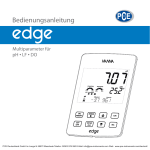
Lovibond® Water Testing
w
.s
sb
-b
er
SD 320 Con
lin
.d
e
Tintometer® Group
w
Leitfähigkeit • Conductivity
w
DE
GB
Bedienungsanleitung
Seite 3
Instruction Manual
Page 30
www.lovibond.com
Name des Herstellers:
lin
.d
e
EG-Konformitätserklärung
Tintometer GmbH
Schleefstraße 8 - 12
44287 Dortmund
Deutschland
erklärt, dass dieses Produkt
SD 320 Con
er
Produktname:
sb
-b
den folgenden Normen entspricht, die in der Richtlinie des Rates zur Angleichung der
Rechtsvorschriften der Mitgliedstaaten über die elektromagnetische Verträglichkeit (2004/108/
EG) und der Niederspannungsrichtlinie (2006/95/EG) festgelegt sind.
Für die Beurteilung des Erzeugnisses hinsichtlich elektromagnetischer Verträglichkeit wurden
folgende Normen herangezogen:
.s
EN 61326-1: 2006 (Tabelle 3, Klasse B)
EN 61326-1: 2006 (Anhang A, Klasse B)
w
w
Diese Erklärung wird verantwortlich für den Hersteller abgeben durch
w
Dortmund, 20. Januar 2013
Cay-Peter Voss, Geschäftsführer
Inhaltsverzeichnis
DE
w
w
w
.s
sb
-b
er
lin
.d
e
1. Allgemeiner Hinweis. . . . . . . . . . . . . . . . . . . . . . . . . . . . . . . . . . . . . . . . . . . . . . . . . 4
2. Sicherheit. . . . . . . . . . . . . . . . . . . . . . . . . . . . . . . . . . . . . . . . . . . . . . . . . . . . . . . . . 4
2.1 Bestimmungsgemäße Verwendung. . . . . . . . . . . . . . . . . . . . . . . . . . . . . . . . . . . . . . 4
2.2 Sicherheitszeichen und Symbole. . . . . . . . . . . . . . . . . . . . . . . . . . . . . . . . . . . . . . . . 4
2.3 Sicherheitshinweise . . . . . . . . . . . . . . . . . . . . . . . . . . . . . . . . . . . . . . . . . . . . . . . . . 5
3. Produktbeschreibung. . . . . . . . . . . . . . . . . . . . . . . . . . . . . . . . . . . . . . . . . . . . . . . . 6
3.1 Lieferumfang. . . . . . . . . . . . . . . . . . . . . . . . . . . . . . . . . . . . . . . . . . . . . . . . . . . . . . 6
3.2 Betriebs- und Wartungshinweise. . . . . . . . . . . . . . . . . . . . . . . . . . . . . . . . . . . . . . . . 6
4. Bedienung. . . . . . . . . . . . . . . . . . . . . . . . . . . . . . . . . . . . . . . . . . . . . . . . . . . . . . . . 7
4.1. Anzeigeelemente. . . . . . . . . . . . . . . . . . . . . . . . . . . . . . . . . . . . . . . . . . . . . . . . . . . 7
4.2. Bedienelemente. . . . . . . . . . . . . . . . . . . . . . . . . . . . . . . . . . . . . . . . . . . . . . . . . . . . 7
4.3 Anschlüsse. . . . . . . . . . . . . . . . . . . . . . . . . . . . . . . . . . . . . . . . . . . . . . . . . . . . . . . . 8
4.4Aufsteller. . . . . . . . . . . . . . . . . . . . . . . . . . . . . . . . . . . . . . . . . . . . . . . . . . . . . . . . . 8
5. Inbetriebnahme . . . . . . . . . . . . . . . . . . . . . . . . . . . . . . . . . . . . . . . . . . . . . . . . . . . . 9
6. Grundlagen zur Messung. . . . . . . . . . . . . . . . . . . . . . . . . . . . . . . . . . . . . . . . . . . . . 9
6.1 Leitfähigkeitsgrundlagen . . . . . . . . . . . . . . . . . . . . . . . . . . . . . . . . . . . . . . . . . . . . . 9
6.2 Messbereiche und Zell-Konstanten . . . . . . . . . . . . . . . . . . . . . . . . . . . . . . . . . . . . . 9
6.3 Leitfähigkeits-Messung. . . . . . . . . . . . . . . . . . . . . . . . . . . . . . . . . . . . . . . . . . . . . . 10
6.4 Messung des spezifischen Widerstandes. . . . . . . . . . . . . . . . . . . . . . . . . . . . . . . . . 11
6.5 Filtrattrockenrückstand/ TDS-Messung . . . . . . . . . . . . . . . . . . . . . . . . . . . . . . . . . . 11
6.6 Salzgehaltsmessung/ Salinitätsmessung . . . . . . . . . . . . . . . . . . . . . . . . . . . . . . . . . 12
6.7 Elektroden/ Messzellen. . . . . . . . . . . . . . . . . . . . . . . . . . . . . . . . . . . . . . . . . . . . . . 12
6.7.1 Belegung Bajonet-Anschluss. . . . . . . . . . . . . . . . . . . . . . . . . . . . . . . . . . . . . . . . . . 12
6.7.2 Aufbau und Auswahl. . . . . . . . . . . . . . . . . . . . . . . . . . . . . . . . . . . . . . . . . . . . . . . 12
6.8Temperaturkompensation. . . . . . . . . . . . . . . . . . . . . . . . . . . . . . . . . . . . . . . . . . . . 13
6.8.1 Temperaturkompensation „nLF“ nach EN 27888 . . . . . . . . . . . . . . . . . . . . . . . . . . 13
6.8.2 Lineare Temperaturkompensation und Ermittlung des
Temperaturkoeffizienten “t.Lin“. . . . . . . . . . . . . . . . . . . . . . . . . . . . . . . . . . . . . . . 13
7. Konfiguration des Gerätes . . . . . . . . . . . . . . . . . . . . . . . . . . . . . . . . . . . . . . . . . . . 14
8. Datenlogger. . . . . . . . . . . . . . . . . . . . . . . . . . . . . . . . . . . . . . . . . . . . . . . . . . . . . . 20
8.1. Manuelle Aufzeichnung („Func-Stor“) . . . . . . . . . . . . . . . . . . . . . . . . . . . . . . . . . . 20
8.2. Automatische Aufzeichnung mit einstellbarem Zyklus „Func CYCL“. . . . . . . . . . . . 21
9. Universalausgang. . . . . . . . . . . . . . . . . . . . . . . . . . . . . . . . . . . . . . . . . . . . . . . . . . 22
9.1. Schnittstelle. . . . . . . . . . . . . . . . . . . . . . . . . . . . . . . . . . . . . . . . . . . . . . . . . . . . . . 22
9.2. Analogausgang . . . . . . . . . . . . . . . . . . . . . . . . . . . . . . . . . . . . . . . . . . . . . . . . . . . 23
10. Justieren des Temperatureingangs. . . . . . . . . . . . . . . . . . . . . . . . . . . . . . . . . . . . . . 23
11. Automatischer Abgleich der Zellkonstante . . . . . . . . . . . . . . . . . . . . . . . . . . . . . . . 24
12. GLP . . . . . . . . . . . . . . . . . . . . . . . . . . . . . . . . . . . . . . . . . . . . . . . . . . . . . . . . . . . . 25
12.1. Abgleich-Intervall (C.Int). . . . . . . . . . . . . . . . . . . . . . . . . . . . . . . . . . . . . . . . . . . . . 25
12.2. Abgleich-Datenspeicher (rEAd CAL) . . . . . . . . . . . . . . . . . . . . . . . . . . . . . . . . . . . . 25
13. Alarm („AL.“). . . . . . . . . . . . . . . . . . . . . . . . . . . . . . . . . . . . . . . . . . . . . . . . . . . . . 26
14. Echtzeituhr („CLOC“). . . . . . . . . . . . . . . . . . . . . . . . . . . . . . . . . . . . . . . . . . . . . . . 26
15.Batteriewechsel . . . . . . . . . . . . . . . . . . . . . . . . . . . . . . . . . . . . . . . . . . . . . . . . . . . 26
16. Fehler- und Systemmeldungen. . . . . . . . . . . . . . . . . . . . . . . . . . . . . . . . . . . . . . . . 27
17. Rücksendung und Entsorgung . . . . . . . . . . . . . . . . . . . . . . . . . . . . . . . . . . . . . . . . 28
17.1Rücksendung. . . . . . . . . . . . . . . . . . . . . . . . . . . . . . . . . . . . . . . . . . . . . . . . . . . . . 28
17.2Entsorgung. . . . . . . . . . . . . . . . . . . . . . . . . . . . . . . . . . . . . . . . . . . . . . . . . . . . . . . 28
18. Technische Daten. . . . . . . . . . . . . . . . . . . . . . . . . . . . . . . . . . . . . . . . . . . . . . . . . . 28
SD 320_1 03/2013
3
1. Allgemeiner Hinweis
Lesen Sie dieses Dokument aufmerksam durch und machen Sie sich mit der Bedienung
des Gerätes vertraut, bevor Sie es einsetzen. Bewahren Sie dieses Dokument griffbereit
und in unmittelbarer Nähe des Geräts auf, damit Sie oder das Fachpersonal im Zweifelsfall
jederzeit nachschlagen können.
Montage, Inbetriebnahme, Betrieb, Wartung und Außerbetriebnahme dürfen nur von
fachspezifisch qualifiziertem Personal durchgeführt werden. Das Fachpersonal muss die
Betriebsanleitung vor Beginn aller Arbeiten sorgfältig durchgelesen und verstanden haben.
lin
.d
e
Die Haftung und Gewährleistung des Herstellers für Schäden und Folgeschäden erlischt
bei bestimmungswidriger Verwendung, Nichtbeachten dieser Betriebsanleitung, Einsatz
ungenügend qualifizierten Fachpersonals sowie eigenmächtiger Veränderung am Gerät.
Der Hersteller haftet nicht für Kosten oder Schäden, die dem Benutzer oder Dritten durch
den Einsatz dieses Geräts, vor allem bei unsachgemäßem Gebrauch des Geräts oder bei
Missbrauch oder Störungen des Anschlusses oder des Geräts, entstehen.
Der Hersteller übernimmt keine Haftung bei Druckfehlern.
er
2. Sicherheit
2.1 Bestimmungsgemäße Verwendung
w
w
.s
sb
-b
Das Gerät ist für die Messung von Leitfähigkeit, spezifischem Widerstand, Salzgehalt und TDS
unter Verwendung von geeigneten Elektroden (Messzellen) ausgelegt. Der Elektrodenanschluss
erfolgt über einen 7poligen Bajonett-Anschluss.
Bitte Beachten: Je nach Messbereich können unterschiedliche Elektrodentypen notwendig
sein – auf geeignete Auswahl achten
Es besteht die Möglichkeit einen Temperaturfühler (Pt1000 oder NTC 10k) ebenfalls über den
7poligen Bajonett-Anschluss anzuschließen. In der Regel ist bereits ein passender Temperaturfühler in der Elektrode integriert. Die gemessene Temperatur wird von der automatischen
Temperaturkompensation (z.B. Lin oder nlF) der Messung verwendet und wird zusätzlich
angezeigt.
Die Sicherheitshinweise dieser Bedienungsanleitung müssen beachtet werden (siehe unten).
Das Gerät darf nur unter den Bedingungen und für die Zwecke eingesetzt werden, für die
es konstruiert wurde.
Das Gerät muss pfleglich behandelt und gemäß den technischen Daten eingesetzt werden
(nicht werfen, aufschlagen, etc.). Vor Verschmutzung schützen.
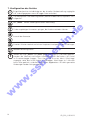
2.2 Sicherheitszeichen und Symbole
w
Warnhinweise sind in diesem Dokument wie folgt gekennzeichnet:
!
1. Warnung! Symbol warnt vor unmittelbar drohender Gefahr, Tod,
schweren Körperverletzungen bzw. schweren Sachschäden bei
Nichtbeachtung.
2. Achtung! Symbol warnt vor möglichen Gefahren oder schädlichen
Situationen, die bei Nichtbeachtung Schäden am Gerät bzw. an der
Umwelt hervorrufen.
i
4
3. Hinweis! Symbol weist auf Vorgänge hin, die bei Nichtbeachtung
einen indirekten Einfluss auf den Betrieb haben oder eine nicht
vorhergesehene Reaktion auslösen können.
SD_320_1 03/2013
2.3 Sicherheitshinweise
Dieses Gerät ist gemäß den Sicherheitsbestimmungen für elektronische Messgeräte gebaut und
geprüft. Die einwandfreie Funktion und Betriebssicherheit des Gerätes kann nur gewährleistet
werden, wenn bei der Benutzung die allgemein üblichen Sicherheitsvorkehrungen sowie die
gerätespezifischen Sicherheitshinweise dieser Betriebsanleitung beachtet werden.
2.
!
sb
-b
!
Betreiben Sie das Gerät nicht mit einem defekten oder beschädigten Netzteil.
Lebensgefahr durch Stromschlag!
!
Dieses Gerät ist nicht für Sicherheitsanwendungen, Not-Aus Vorrichtungen
oder Anwendungen bei denen eine Fehlfunktion Verletzungen und materiellen
Schaden hervorrufen könnte, geeignet. Wird dieser Hinweis nicht beachtet,
könnten schwere gesundheitliche und materielle Schäden auftreten.
w
4.
Konzipieren Sie die Beschaltung beim Anschluss an andere Geräte besonders sorgfältig.
Unter Umständen können interne Verbindungen in Fremdgeräten (z.B. Verbindung GND
mit Erde) zu nicht erlaubten Spannungspotentialen führen, die das Gerät selbst oder ein
angeschlossenes Gerät in seiner Funktion beeinträchtigen oder sogar zerstören können.
.s
3.
Wenn anzunehmen ist, dass das Gerät nicht mehr gefahrlos betrieben werden
kann, so ist es außer Betrieb zu setzen und vor einer weiteren Inbetriebnahme
durch Kennzeichnung zu sichern. Die Sicherheit des Benutzers kann durch das
Gerät beeinträchtigt sein, wenn es z.B.
- sichtbare Schäden aufweist.
- nicht mehr wie vorgeschrieben arbeitet. - längere Zeit unter ungeeigneten Bedingungen gelagert wurde.
Im Zweifelsfall Gerät zur Reparatur oder Wartung an den Hersteller schicken.
er
lin
.d
e
1. Funktion und Betriebssicherheit des Gerätes können nur unter den klimatischen Verhältnissen, die im Kapitel "Technische Daten" spezifiziert sind, eingehalten werden.
Wird das Gerät von einer kalten in eine warme Umgebung transportiert, kann durch Kondensatbildung eine Störung der Gerätefunktion eintreten. In diesem Fall muss die Angleichung
der Gerätetemperatur an die Raumtemperatur vor einer Inbetriebnahme abgewartet werden.
!
Dieses Gerät darf nicht in einer explosionsgefährdeten Umgebung eingesetzt werden. Bei Betrieb in explosionsgefährdeter Umgebung besteht
erhöhte Verpuffungs-, Brand-, oder Explosionsgefahr durch Funkenbildung.
w
w
5.
SD 320_1 03/2013
5
3. Produktbeschreibung
3.1 Lieferumfang
Im Standard-Lieferumfang enthalten:
- SD 320 Con mit 2 AAA-Batterien
- Elektrode
- Betriebsanleitung
lin
.d
e
3.2 Betriebs- und Wartungshinweise
1. Batteriebetrieb:
Wird in der unteren Anzeige ´bAt´ angezeigt, so sind die Batterien verbraucht und müssen erneuert werden. Die Gerätefunktion ist jedoch noch für eine gewisse Zeit gewährleistet. Wird in der
oberen Anzeige ´bAt´ angezeigt, so reicht die Batteriespannung für den Gerätebetrieb nicht mehr
aus, die Batterie ist nun ganz verbraucht. Batteriewechsel siehe Kapitel "14. Batteriewechsel".
Bei Lagerung des Gerätes bei über 50 °C Umgebungstemperatur muss die Batterie entnommen werden. Wird das Gerät längere Zeit nicht benutzt, sollte die Batterie
herausgenommen werden. Die Uhrzeit muss nach Wiederinbetriebnahme jedoch
erneut eingestellt werden.
er
i
2. Gerät und Sensoren/Elektroden müssen pfleglich behandelt werden und gemäß
den technischen Daten eingesetzt werden (nicht werfen, aufschlagen, etc.). Stecker
und Buchsen sind vor Verschmutzung zu schützen.
w
w
w
.s
sb
-b
3. USB:
Achten Sie beim Anschluss des USB-Schnittstellenkabels darauf, nur zulässige Komponenten
anzuschließen.
Empfohlen wird der Betrieb mit dem Schnittstellenkabel USB 300. Wird dieses verwendet, versorgt sich dass Gerät aus der USB-Schnittstelle des verbundenen PC’s oder USB-Netzteiladapters.
6
SD_320_1 03/2013
4. Bedienung
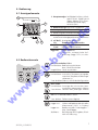
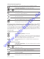
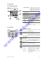
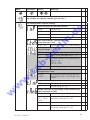
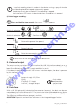
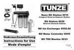
4.1 Anzeigeelemente
3
kΩ•cm MΩ•cm mS µS mg
cm cm l SAL
1
°C
MAX
HLD
DIF MIN
5
nLF NaCl
2. Nebenanzeige: Messwert Temperatur
2
°C
°F
Lin
%
K
7
4. Bewertung des Batteriezustandes
5. Anzeigeelemente zur Darstellung des minimalen/maximalen/gespeicherten Messwertes
1 Logg
cm
6
3. Anzeigepfeile für Messwert-Einheiten
lin
.d
e
4
1. Hauptanzeige:Leitfähigkeit (mS/cm, µS/cm)
spezifischer Widerstand
(kΩcm, MΩcm) TDS, Filtrat
trockenrückstand (mg/l), Salinität (SAL)
8
6. nLF NaCl, Anzeige der gewählten Temperaturkompensation
Lin:
7. %/K, zusätzliche 1/cm:Konfigurationseinheiten
sb
-b
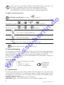
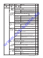
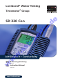
4.2 Bedienelemente
Logger ist bereit.
Pfeil blinkt: automatische Aufzeichnung (Logg CYCL) ist aktiv.
er
logg-Pfeil:
w
w
w
.s
2 Con
Ein- / Ausschalter, Licht
kurz drücken: Beleuchtung aktivieren
bzw. Gerät einschalten
lang drücken: Gerät ausschalten
set / menu:
kurz drücken: manuelle Temperatureingabe,
wenn kein Temperaturfühler ange
schlossen ist.
2 sec. drücken (Menu): Aufruf der Konfiguration
min / max:
kurz drücken:Anzeige des minimalen bzw.
maximalen gemessenen Wertes
2 sec.drücken: Löschen des jeweiligen Wertes
cal: nur im Betriebsmodus ’cond’:
2 sec. drücken: Zellkonstanten-Abgleich
store / enter:
Logger aus: Halten und Speichern des aktuellen
Messwertes (’HLD’ in Display)
Logger an: Bedienung des Datenloggers –
Kap. Datenlogger
Set/Menu: Bestätigung von Eingaben, Rück
kehr zur Messung
SD 320_1 03/2013
7
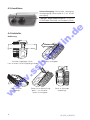
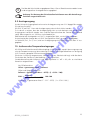
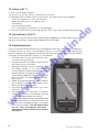
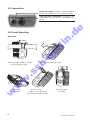
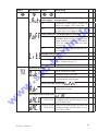
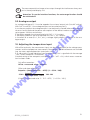
4.3 Anschlüsse
Universalausgang: Schnittstelle, Versorgung,
Analogausgang (siehe Kapitel 9.1, 9.2 Universalausgang)
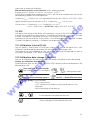
4.4 Aufsteller
Bedienung:
sb
-b
er
Ziehen
lin
.d
e
7-poliger Bajonettenanschluss: Anschluss
für Elektrode / Messzelle und Temperaturfühler
Aufsteller ausklappen.
w
w
.s
Aufsteller zugeklappt. Gerät kann an einem Gürtel aufgehängt werden.
Gerät am Tisch
aufgestellt.
w
8
Ziehen Sie an Beschriftung
"open", um Aufsteller
weiter auszuklappen.
Gerät an Schraube aufgehängt.
SD_320_1 03/2013
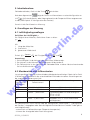
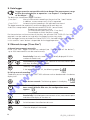
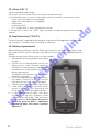
5. Inbetriebnahme
Elektrode verbinden, Gerät mit der Taste
einschalten.
zeigt das Gerät kurz Informationen zu seiner Konfiguration an:
Nach dem Segmenttest
falls eine Nullpunkt- oder Steigungskorrektur des Temperaturfühlers vorgenommen
(z.B.
wurde (siehe Kapitel 10. Konfiguration des Gerätes)).
6. Grundlagen zur Messung
6.1 Leitfähigkeitsgrundlagen
lin
.d
e
Danach ist das Gerät bereit zur Messung.
Mit
l: Länge des Materiales
A: Querschnitt “
R: gemessener Widerstand
er
Definition der Leitfähigkeit γ:
Die Fähigkeit eines Materials, elektrischen Strom zu leiten:
γ = l
(R•A)
sb
-b
[γ] = Siemens = S , bei Flüssigkeiten üblich: mS und µS
Einheit:
cm
cm
Meter m
Anmerkung
1. Die Leitfähigkeit ist der Kehrwert des spezifischen Widerstandes.
2. Der Leitwert ist der Kehrwert des gemessenen Widerstandes R.
3. Die Zellkonstante ist das Verhältnis der Elektrodenfläche zu deren Abstand voneinander.
Sie hat die Masseinheit cm-1.
.s
6.2 Messbereiche und Zellkonstanten
w
Je nach gewählter Elektrode sind verschiedene Messbereiche realisierbar. Dabei sind im Gerät
4 Zellkonstanten-Bereiche für die unterschiedlichen Elektroden einstellbar. Diese hängen von
der zugehörigen Zellkonstante K ab:
w
w
CELL rAnG
(Zellkonstanten-Bereich)
0.01
0.1
1
10
Einstellbare
Zellkonstante K
Beispiele für Anwendungen
0,004000 - 0,015000•1/cm Reinstwasser, Elektroden mit K = 0.01
0,04000 - 0,15000•1/cm
Reinstwasser, Elektroden mit K = 0.1
0,4000 - 1,5000•1/cm
Standardelektroden im Lieferumfang z.B.
SET1 K = 0.55
SET2 K = 0.40
4,000 - 15,000 •1/cm
Elektroden mit K = 10 (für extrem hohe
Leitfähigkeiten)
Die Zellkonstante K kann manuell über die Konfiguration (siehe Kapitel 7 „Konfiguration
des Gerätes“) eingegeben oder über die Abgleichfunktion bestimmt werden. Dabei gibt es
zwei Möglichkeiten:
- automatisch mit Referenzlösungen (Temperaturkompensiert)
- trimmen der Anzeige bei bekanntem Lösungswert
SD 320_1 03/2013
9
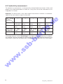
6.3 Leitfähigkeits-Messung
Die Leitfähigkeitsmessung ist eine vergleichsweise unkomplizierte Messung. Die Standardelektroden sind bei sachgemäßer Verwendung über lange Zeit stabil, und können über die
integrierte Cal-Funktion abgeglichen werden.
Achtung: Das Gerät deckt einen sehr weiten Messbereich ab, allerdings muss eine für den
Messbereich geeignete Elektrode verwendet werden.
0.1
1 (siehe Lieferumfang)
10
2
3
4
5
0,000 5,000 µS/cm
0,00 - 50,00
µS/cm
0,0 - 500,0
µS/cm
0,00 - 50,00
µS/cm
0,0 - 500,0
µS/cm
0 - 5000
µS/cm
0,0 - 500,0
µS/cm
0 - 5000
µS/cm
0,00 - 50,00
mS/cm
0 - 5000
µS/cm
0,00 - 50,00
mS/cm
0,0 - 500,0
mS/cm
0,00 - 50,00
mS/cm
0,0 - 500,0
mS/cm
0 - 1000
mS/cm
0 - 5000
µS/cm
0,00 - 50,00
mS/cm
0,0 - 500,0
mS/cm
0 - 1000
mS/cm
---
lin
.d
e
0.01
1
er
Bereich
CELL
- rAnG
w
w
w
.s
sb
-b
Ist die Bereichswahl auf „Auto Range“ eingestellt, wird automatisch der Bereich mit der
besten Auflösung gewählt, der Logger- oder Schnittstellenbetrieb verlangt allerdings eine
feste Vorauswahl des Messbereiches aus obiger Tabelle (Kein Logger/Schnittstellenbetrieb
mit Auto-Range!).
10
SD_320_1 03/2013
6.4Messung des spezifischen Widerstandes
0.01
0,10 - 50,00
kOhm•cm
0.1
0,010
- 5,000
kOhm•cm
1 (siehe Lie- 0,0010
ferumfang) - 0,5000
kOhm•cm
10
---
2
0,1 - 500,0
kOhm•cm
0,01 - 50,00
kOhm•cm
0,001
- 5,000
kOhm•cm
0,0001
- 0,5000
kOhm•cm
3
4
0,000
- 5,000
MOhm•cm
0,0 - 500,0
kOhm•cm
5
0,000
- 50,00
MOhm•cm
0,000
- 5,000
MOhm•cm
0,0 - 500,0
kOhm•cm
0,00 - 50,00
mS/cm
0,00 - 50,00
kOhm•cm
---
0,0 - 500,0
mS/cm
lin
.d
e
1
Bereich
CELL
- rAnG
0,00 - 50,00
kOhm•cm
0,000
- 5,000
kOhm•cm
0 - 1000
mS/cm
er
Ist die Bereichswahl auf „Auto Range“ eingestellt, wird automatisch der Bereich mit der
besten Auflösung gewählt, der Logger- oder Schnittstellenbetrieb verlangt allerdings eine
feste Vorauswahl des Messbereiches aus obiger Tabelle (Kein Logger/Schnittstellenbetrieb
mit Auto-Range!)
sb
-b
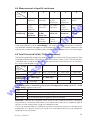
6.5 Filtrattrockenrückstand / TDS-Messung
Mit der TDS-Messung (total dissolved solids) wird anhand der Leitfähigkeit und eines Umrechnungsfaktors (C.tdS) der Filtrattrockenrückstand (Abdampfrückstand) bestimmt und ist daher
gut geeignet, um einfache Konzentrationsmessungen von z.B. Salzlösungen durchzuführen.
Die Anzeige erfolgt in mg/l.
1
.s
Bereich
CELL
- rAnG
0.01
0.1
1 (siehe Lieferumfang)
10
2
3
4
0,00 - 50,00 mg/l 0,0 - 500,0 mg/l 0 - 5000 mg/l
0,0 - 500,0 mg/l 0 - 5000 mg/l
--0 - 5000 mg/l
-----
0 - 5000 mg/l
---
---
---
w
w
w
0,000 - 5,000 mg/l
0,00 - 50,00 mg/l
0,0 - 500,0 mg/l
Anzeigewert TDS = Leitfähigkeit [in µs/cm, nLF-temperaturkomp. auf 25 °C] • C.tdS
(Menüeingabe). Näherungsweise gilt:
C.tdS
0,50
0,50
0,65 - 0,70
einwertige Salze mit 2 Ionenarten (NaCl, KCl, u.ä.)
Natürliche Wässer/Oberflächenwässer, Trinkwasser
z.B Salzkonzentration von wässrigen Düngerlösungen
Achtung: Dies sind nur Anhaltswerte und daher gut geeignet für Abschätzungen (keine
präzisen Messungen). Für präzise Messungen muss der Umrechnungsfaktor für die jeweilige
Art der Lösung und den betrachteten Konzentrationsbereich ermittelt werden.
Dies kann entweder mit Abgleich auf bekannte Vergleichslösungen oder durch tatsächliches
Verdampfen einer bestimmten Menge der Flüssigkeit mit vermessener Leitfähigkeit und anschließendes Wiegen des Trockenrückstandes bewerkstelligt werden.
SD 320_1 03/2013
11
6.6 Salzgehaltsmessung/Salinitätsmessung
lin
.d
e
In der Messart „SAL“ kann die Salinität (Salzgehalt) von Meerwasser bestimmt werden
(Grundlage: International Oceanographic Tables; IOT). Standardmeerwasser hat eine Salinität
von 35 ‰ (35 g Salz pro 1 kg Meerwasser).
Die Anzeige erfolgt in der Regel Einheitenlos in ‰ (g/kg).
Ebenso gebräuchlich ist die Bezeichnung „PSU“ (Practical Salinity Unit), der Anzeigewert
dafür ist identisch.
Die Salinitätsmessung hat eine „eigene“ Temperaturkompensation, d.h. die Temperatur wird
bei der Anzeige berücksichtigt und hat einen großen Einfluss auf den Anzeigewert, etwaige
Menü-Einstellungen hinsichtlich der Temperaturkompensation werden ignoriert.
Achtung: Die Salzzusammensetzung der verschiedenen Meere ist nicht identisch, Je
nach Ort, Wetter, Gezeiten usw. entstehen zum Teil erhebliche Abweichungen von den
35 ‰ nach IOT. Auch die Salzzusammensetzung kann Einfluss auf das Verhältnis der
Salinitätsanzeige zur tatsächlich vorhandenen Salzmenge haben.
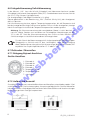
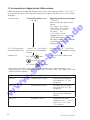
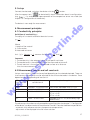
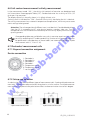
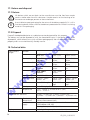
6.7Elektroden / Messzellen
Geräte-Anschluss
Elektrode I+
Elektrode U+
Elektrode UElektrode ITemperatur-Sensor
Temperatur-Sensor
nicht belegt
.s
1:
2:
3:
4:
5:
6:
7:
w
sb
-b
6.7.1 Belegung Bajonet-Anschluss
er
Für viele Salze in der Meerwasseraquaristik sind entsprechende Tabellen verfügbar
(Salzgewicht zu Salinität nach IOT bzw. Leitfähigkeit). Unter Berücksichtigung
dieser Tabellen können sehr präzise Salinitätsmessungen durchgeführt werden (Wir
empfehlen hier Graphit-4pol Messzellen LC 12 oder LC 16).
6.7.2 Aufbau und Auswahl
w
w
Grundsätzlich können zwei unterschiedliche Arten von Messzellen unterschieden werden: 2–Pol
und 4-Pol Messzellen. Die Ansteuerung bzw. Auswertung erfolgt ähnlich. Die 4-Pol Messzellen
können durch das aufwändigere Messverfahren Polarisationseffekte und Verschmutzungen
bis zu einem gewissen Grad gut kompensieren.
12
2–Pol Messzelle
4–Pol Messzelle
SD_320_1 03/2013
Die Auswahl der passenden Elektrode ist vom Anwendungsfall abhängig.
•Das breiteste Anwendungsspektrum bieten hochwertige Graphit-4pol Messzellen (LC 12
oder LC 16, alle zuvor erwähnten Anwendungen und: Meerwasser, Titration, Abwässer).
•Für niedrige Leitfähigkeiten (<100 µS/cm) bieten Edelstahl Messzellen Vorteile (Rein und
Reinstwasser, Kesselwasser, Osmose und Filtertechnik).
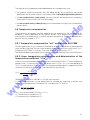
6.8 Temperaturkompensation
lin
.d
e
•Für niedrige Leitfähigkeiten (< 1000 µS/cm) bieten 2pol Platin Elektroden mit Glasschaft
eine gute Lösung (Benzin, Diesel).
Die Leitfähigkeit von wässrigen Lösungen ist abhängig von der Temperatur. Die Temperaturabhängigkeit ist stark von der Art der Lösung abhängig. Durch Temperaturkompensation wird die
Lösung auf eine einheitliche Bezugstemperatur zurückgerechnet um sie temperaturunabhängig
vergleichen zu können. Die übliche Bezugstemperatur dafür ist 25 °C.
6.8.1 Temperaturkompensation „nLF“ nach EN 27888
er
Für die meisten Anwendungen bspw. Im Bereich der Fischzucht und der Messung von Oberflächenwasser und Trinkwasser ist die nichtlineare Temperaturkompensation für natürliche
Wässer („nLF“, nach EN 27888) ausreichend genau. Die übliche Bezugstemperatur ist 25 °C.
Empfohlener Einsatzbereich der nLF- Kompensation: zwischen 60 µS/cm und 1000 µS/cm.
sb
-b
6.8.2 Lineare Temperaturkompensation und Ermittlung des Temperaturkoeffizienten “t.Lin“
Wenn die Funktion der Temperaturkompensation nicht genau bekannt ist, wird in der Praxis im
Gerät eine "lineare Temperaturkompensation" eingestellt (Menu, t.Cor = Lin, t.Lin entspricht
TKlin). Dass heisst, man nimmt vereinfachend an, dass die Temperaturabhängigkeit über den
betrachteten Konzentrationsbereich der Lösung in etwa gleich ist.
w
.s
=
LFTX
LF
Tref
TKlin
1+
• (Tx-Tref)
(100%)
w
w
Temperaturkoeffizienten um 2.0 %/K sind meist üblich.
Ein Temperaturkoeffizient kann beispielsweise ermittelt werden, indem eine Lösung mit
ausgeschalteter Temperaturkompensation bei 2 Temperaturen (T1 und T2) vermessen wird.
LFTref= (LFT1-LFT2) • 100%
(T1-T2) • LFT1
TKlin ist der Wert der im Menu "t.Lin" eingegeben wird
LFT1 Leitfähigkeit bei Temperatur T1
LFT2 Leitfähigkeit bei Temperatur T2
SD 320_1 03/2013
13
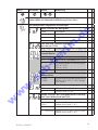
7. Konfiguration des Gerätes
i
Einige Menüpunkte sind abhängig von der aktuellen Geräteeinstellung zugänglich
(z.B. sind einige gesperrt wenn sie Logger Daten enthalten).
Zum Konfigurieren 2 Sekunden lang drücken, dadurch wird das Menü (Hauptmenü "SEt")
aufgerufen.
lin
.d
e
Mit „menu“ wählen Sie den gewünschten Menüzweig.
Zu den zugehörigen Parametern springen, die Sie dann verändern können.
Auswahl der Parameter
Beenden der Konfiguration.
i
er
Erneutes Drücken wechselt zurück zum Hauptmenü und speichert die Einstellungen.
w
w
w
.s
sb
-b
Werden die Tasten „menu“ und „store“ gemeinsam länger als 2 Sekunden gedrückt,
werden die Werkseinstellungen wiederhergestellt Befinden sich Daten
im Einzelwertlogger (Logger: ‘Func Stor’) wird als erstes Menü ‘rEAd Logg’
angezeigt: siehe dazu auch Kapitel 8 Datenlogger. Wird länger als 2 Minuten
keine Taste gedrückt, wird die Konfiguration abgebrochen. Bis dahin gemachte
Änderungen werden nicht gespeichert!
14
SD_320_1 03/2013
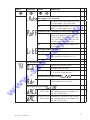
Menü
Parameter
Werte
Bedeutung
rEAd Logg: Lesen der Einzel-Loggerdaten,
siehe Kapitel 8.1! Manuelle Aufzeichnung ("Func-Stor")
Set Configuration: Allgemeine Einstellungen
Cond
Leitfähigkeit
rES:
Spezifischer Widerstand
SAL
Salzgehalt/ Salinität
TDS
Filtrattrockenrückstand
TDS Messung: Umrechnungsfaktor
(nur bei Inp = TDS)
0.40 - 1.00
**
lin
.d
e
Input: Auswahl der Messgröße
.
Umrechnungsfaktor zur TDS-Messung
0.01
Reinstwasser, Elektroden mit K ~ 0.01
Reinstwasser, Elektroden mit K ~ 0.1
sb
-b
0.1
er
Cell Range: Einstellung der Zellkonstante: Zellkonstanten-Bereich
1
Standardelektroden im Lieferumfang z.B.
SET1 K = 0.55
SET2 K = 0.40
10
Elektroden mit K=10
w
w
w
.s
Cell Factor: Einstellung der Zellkonstante: Multiplikationsfaktor
0.3800 1.5000
Multiplikationsfaktor der Zellkonstante
Zellkonstante CELL = CELL Range .
CELL Factor
t-Input: Auswahl des Temperatureingangs
NTC
NTC 10k Fühler (LC 12)
Pt
Pt1000 Fühler (LC 16)
Range: Auswahl des Anzeigebereiches (Leitfähigkeit, spez. Widerstand oder TDS)
Auto
Automatische Bereichswahl
z.B. 0.0 ... 500.0
µS/cm
Beispiel für CELL rAng 1 und InP Cond:
andere siehe Kap 6.3 - 6.5
...
0 ... 1000 mS/cm
SD 320_1 03/2013
Beispiel für CELL rAng 1 und InP Cond:
andere siehe Kap 6.3 - 6.5
15
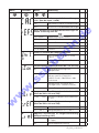
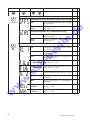
Menü
Parameter
Werte
Bedeutung
Automatische Justierung mit Referenzlösungen
„CAL“ (Nur bei Input = cond)
Edit
Manuelles Einstellen auf Referenzwert
REF.S
Auswahl aus Standard Referenzlösungen
**
lin
.d
e
REF.S: Auswahl aus Standard Referenzlösungen für
autom. Justierung. Nur bei
1413 µS/cm
Referenzlösung 0.01 M KCL
2760 µS/cm
0.02 M KCL
12.88 mS/cm
0.1 M KCL
50 mS/cm
Seewasser-Vergleichslösung KCL
111.8 mS/cm
1 M KCL
°C
Alle Temperaturangaben in Grad
Celsius
Alle Temperaturangaben in Grad
Fahrenheit
sb
-b
°F
er
Einheit t: Auswahl der Temperatureinheit
Temperaturkompensation (Nicht bei INP = SAL und TDS)
Leitfähigkeitsmessung nicht
kompensieren
nLF
nichtlineare Funktion für natürliche
Wässer nach EN 27888 (DIN
38404) Grund-, Oberflächen- oder
Trinkwasser
w
w
w
.s
oFF
NaCl
Kompensation schwacher NaClLösungen (Rein- und Reinstwasser)
Lin
lineare Temperaturkompensation
Kompensationskoeffizient (nur bei t.Cor = Lin)
(Nicht bei INP = SAL und TDS)
0.300 ... 3.000
Temperaturkompensationskoeffizient
in %/K.
Bezugstemperatur der Temperaturkompensation
(Nicht bei INP = SAL und TDS)
25 °C / 77 °F
Bezugstemperatur 25 °C / 77 °F
20 °C / 68 °F
Bezugstemperatur 20 °C / 68 °F
Abgleich: Zeitintervall für Abgleicherinnerung
(Werkseinstellung: OFF)
16
1 … 730
Zeitintervall für Abgleicherinnerung
(in Tagen)
oFF
Keine Abgleicherinnerung
SD_320_1 03/2013
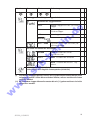
Menü
Parameter
Werte
Bedeutung
Auto Hold: Automatische Messwertermittlung (nur
bei Logger = oFF wirksam)
Automatische Messwertermittlung
(nur bei Logger = oFF) Auto Hold
oFF
Standard-Holdfunktion auf Tastendruck (nur bei Logger = oFF)
lin
.d
e
on
Auto Power-Off : Automatische Geräteabschaltung.
Abschaltverzögerung in Minuten. Wird
keine Taste gedrückt und findet kein
Datenverkehr über die Schnittstelle
statt, schaltet sich das Gerät nach Ablauf dieser Zeit automatisch ab
oFF
automatische Abschaltung deaktiviert
(Dauerbetrieb)
er
1...120
Hintergrundbeleuchtung
oFF
Keine Beleuchtung
Beleuchtung nach 5.. 120 s automatisch abschalten (Werkseinst.: 5 s)
on
Beleuchtung immer an
sb
-b
5 … 120
Universeller Ausgang
SEr
serielle Schnittstelle aktiviert
dAC
Analogausgang aktiviert
oFF
Schnittstelle und Analogausgang aus
-> minimaler Stromverbrauch
Serielle Schnittstelle (nur bei
01,11 ... 91
Analogausgang (nur bei
w
w
w
.s
0.0000 µS/cm
... 1000 mS/cm
0.0000 µS/cm
... 1000 mS/cm
SD 320_1 03/2013
=
)
Basisadresse des Gerätes für serielle
Schnittstellenkommunikation.
=
)
Eingabe der Messwertes bei welchem
der Analogausgang 0V ausgeben soll,
z.B. bei 0,0000 µS/cm
Eingabe des Messwertes bei welcher
der Analogausgang 1V ausgeben soll,
z.B. bei 100,0 mS/cm
17
Menü
Parameter
Werte
Bedeutung
Set Corr: Justage der Messungen
**
Nullpunktkorrektur/Offset der Temperaturmessung **
keine Nullpunktkorrektur der Temperaturmessung
-5.0 …
5.0 %
Nullpunktkorrektur der Temperaturmessung in °C
lin
.d
e
oFF
Steigungskorrektur der Temperaturmessung
oFF
keine Steigungskorrektur der Temperaturmessung
-5.0 …
5.0 %
Steigungskorrektur der Temperaturmessung in %
**
Set Alarm: Einstellung der Alarmfunktion
Messkanal cond/rES/TDS/SAL: Alarm
an ohne Ton
sb
-b
No.So
Messkanal cond/rES/TDS/SAL: Alarm
an mit Ton
er
On
OFF
keine Alarmfunktion für Messkanal
cond/rES/TDS/SAL
0.0000 µS/cm Min-Alarm-Grenze cond/rES/TDS/SAL
... 1000 mS/cm (nicht bei AL. 1. oFF)
w
w
w
.s
0.0000 µS/cm Max-Alarm-Grenze cond/rES/TDS/SAL
... 1000 mS/cm (nicht bei AL. 1. oFF)
18
On
Alarm Temperaturmessung an mit Ton
No.So
Alarm Temperaturmessung Alarm an
ohne Ton
OFF
keine Alarmfunktion für Temperaturmessung
-5.0 ...
+100.0 °C
Min-Alarm-Grenze Temperatur (nicht
bei AL. 2. oFF)
-5.0 ...
+100.0 °C
Max-Alarm-Grenze Temperatur (nicht
bei AL. 2. oFF)
SD_320_1 03/2013
Menü
Parameter
Werte
Bedeutung
Set Logger: Einstellung der Loggerfunktion
Auswahl der Loggerfunktion
Cyclic: Loggerfunktion zyklischer
Logger
Stor
Store: Loggerfunktion
Einzelwertlogger
oFF
keine Loggerfunktion
Nur bei
0:01 ... 60:00
*
lin
.d
e
CYCL
**
Zykluszeit in [Minuten:Sekunden] bei
zyklischem Logger
**
er
Set Clock: Einstellen der Echtzeituhr
Clock: Einstellen der Uhrzeit
Stunden:Minuten
sb
-b
HH:MM
YYYY
Year: Einstellen der Jahreszahl
TT.MM
Date: Einstellen des Datums Tag.
Monat
.s
rEAd CAL: Lesen der Kalibrierdaten:
siehe Kapitel 12.2 Abgleich-Datenspeicher (rEAd CAL)
w
w
w
(*) Sind Daten im Loggerspeicher, können mit (*) gekennzeichnete Parameter nicht
aufgerufen werden. Sollen diese verändert werden, müssen zunächst die Daten
gelöscht werden!
(**) Bei laufendem Logger können Parameter die mit (**) gekennzeichnet sind nicht
aufgerufen werden.
SD 320_1 03/2013
19
8. Datenlogger
8.1 Manuelle Aufzeichnung („Func-Stor“)
lin
.d
e
Kein Loggerbetrieb mit Auto-Range möglich! Es muss eine feste Vorauswahl
des Messbereiches getroffen werden – siehe Kapitel 7 „Konfiguration des Gerätes“ Das Gerät besitzt zwei verschiedene Loggerfunktionen:
„Func-Stor“: manuelle Messwertaufzeichnung per Tastendruck „store“
Zusätzlich wird eine Messstelleneingabe (L-Id)gefordert.
„Func-CYCL“: automatische Aufzeichnung im Abstand der eingestellten Zykluszeit
Der Logger zeichnet jeweils die Leitfähigkeit und die Temperatur pro Datensatz auf.
Ein Datensatz besteht aus: Messwert cond/rES/TDS/SAL (einer davon)
Messwert Temperatur
Messstelle L-Id (nur bei „Func-Stor“)
Uhrzeit und Datum zum Zeitpunkt des Speicherns
Zur Auswertung und Übertragung der Daten benötigen sie die Software GSOFT3050, mit der
die Loggerfunktion sehr einfach gestartet und eingestellt werden kann.
Bei aktivierter Loggerfunktion (Func Stor oder Func CYCL) steht die Hold Funktion nicht zur
Verfügung, die Taste „store“ ist dann für die Loggerbedienung zuständig.
er
a) Messwerte manuell aufzeichnen:
Wurde die Loggerfunktion „Func Stor“ gewählt (siehe „Konfigurieren des Gerätes“),
können maximal 1000 Messungen manuell abgespeichert werden:
kurz drücken: Datensatz wird abgespeichert (es wird kurz „St. XX“
angezeigt. XX ist Nummer des Datensatzes.)
sb
-b
Messstelleneingabe „L-Id“: Auswahl der Messstelle über Tasten.
Zahl von 0 … 19999.
oder
Die Eingabe wird bestätigt.
Falls der Loggerspeicher voll ist, erscheint
w
.s
b) Manuelle Aufzeichnung abrufen:
Abgespeicherte Datensätze können sowohl mit der PC-Software GSOFT3050 ausgelesen, als
auch in der Geräteanzeige selbst betrachtet werden.
w
w
i
oder
2 Sekunden lang drücken: Im Display erscheint:
„rEAd LoGG“ erscheint nur, wenn bereits Datensätze abgespeichert worden sind! Ohne Datensätze erscheint das Konfigurationsmenü
Kurz drücken: Wechsel zwischen Messwerten, Messstelle- und Datum+Uhrzeit-Anzeige des Datensatzes
Wechsel zwischen den Datensätzen
Anzeige der Aufzeichnungen beenden
20
SD_320_1 03/2013
c) Manuelle Aufzeichnung löschen:
Sind bereits Daten gespeichert, können diese über die Store-Taste gelöscht werden:
2 Sekunden lang drücken: Aufruf des Lösch-Menüs
oder
Wechsel der Auswahl
nichts löschen (Vorgang abbrechen)
Alle Datensätze löschen
lin
.d
e
den zuletzt aufgezeichneten Datensatz löschen
Bestätigung der Auswahl, Ende des Lösch-Menü
er
8.2 Automatische Aufzeichnung mit einstellbarem Zyklus „Func CYCL“
sb
-b
Wurde die Loggerfunktion „Func CYCL“ gewählt (siehe „Konfiguration des Gerätes“) werden
nach Start des Loggers automatisch Messwerte im Abstand der eingestellten Zykluszeit aufgezeichnet. Die Logger-Zykluszeit ist einstellbar von 1 s bis 60 min (siehe „Konfiguration des Gerätes“).
Speicherbare Datensätze: 10000. Die automatisch gespeicherten Werte können nur am PC
angezeigt werden.
a) Loggeraufzeichnung starten:
2 Sekunden lang drücken: Startauswahl
.s
Danach nochmals drücken: automatische Aufzeichnung wird gestartet.
Jeder Speichervorgang wird durch kurze Anzeige von ‘St.XXXXX‘ signalisiert.
XXXXX steht hierbei für die Nummer des Datensatzes.
Falls der Loggerspeicher voll ist, wird die Aufzeichnung automatisch gestoppt.
w
w
w
b) Loggeraufzeichnung stoppen:
2 Sekunden lang drücken: : Falls eine Aufzeichnung läuft, erscheint
das Stopp-Menü
oder
Wechsel der Auswahl
Die Aufzeichnung nicht stoppen (Vorgang abbrechen)
Aufzeichnung stoppen
Bestätigung der Auswahl, Ende des Lösch-Menü
SD 320_1 03/2013
21
i
Wird versucht ein mit zyklischer Aufzeichnung laufendes Gerät auszuschalten, wird
automatisch nachgefragt, ob die Aufzeichnung gestoppt werden soll.
Nur bei gestoppter Aufzeichnung kann das Gerät abgeschaltet werden.
Die Auto-Power-Off Funktion ist bei laufender Aufzeichnung deaktiviert!
c) Loggeraufzeichnung löschen:
2 Sekunden lang drücken: Startmenü "
oder
:
Wechsel der Auswahl:
oder
: Mit
bestätigen.
nichts löschen (Vorgang abbrechen)
Alle Datensätze löschen
sb
-b
bestätigen.
er
: Mit
lin
.d
e
Wechsel der Auswahl:
" erscheint.
den zuletzt aufgezeichneten Datensatz löschen
Bestätigung der Auswahl, Ende des Lösch-Menü
.s
9. Universalausgang
w
Der Ausgang kann entweder als serielle Schnittstelle (für USB 300 Schnittstellenadapter) oder
als Analogausgang (0-1V) verwendet werden. Wird der Ausgang nicht benötigt, sollte er
deaktiviert werden (Out oFF), da sich dadurch der Batterieverbrauch stark reduziert.
Wird das Gerät mit dem universellen Schnittstellenadapter USB 300 betrieben, versorgt sich
das Gerät aus dieser Schnittstelle.
w
w
Steckerbelegung:
4: externe Versorgung +5V, 50mA
3: GND
2: TxD/RxD (3.3V Logik)
1: +UDAC, Analogausgang
Nur geeignete Adapterkabel
sind zulässig
(Zubehör)
9.1 Schnittstelle
Mit einem galv. getrennten Schnittstellenwandler USB 300 (Zubehör) kann das Gerät direkt
an eine USB-Schnittstelle eines PC angeschlossen werden. Die Übertragung erfolgt in einem
binärcodierten Format und ist durch aufwendige Sicherheitsmechanismen gegen Übertragungsfehler geschützt (CRC).
Folgendes Standard - Softwarepaket steht zur Verfügung:
GSOFT3050: Bedien- und Auswertesoftware für die integrierte Loggerfunktion
22
SD_320_1 03/2013
i
Die über die Schnittstelle ausgegebenen Mess-/ Alarm-/ Bereichswerte werden immer
in der eingestellten Anzeigeeinheit ausgegeben!
Achtung: Zur Nutzung der Schnittstellenfunktionen muss die Auto-RangeFunktion ausgeschaltet sein.
9.2 Analogausgang
lin
.d
e
An der Universal-Ausgangsbuchse kann eine Analogspannung von 0-1V abgegriffen werden
(Einstellung Out dAC).
Mit DAC.0 und DAC.1 kann der Analogausgang sehr einfach skaliert werden.
Es ist darauf zu achten, dass der Analogausgang nicht zu stark belastet wird, da sonst der
Ausgangswert verfälscht werden kann und die Stromaufnahme des Gerätes entsprechend
steigt. Belastungen bis ca. 10kOhm sind unbedenklich.
Überschreitet die Anzeige den mit DAC.1 eingestellten Wert, so wird 1V ausgegeben
Unterschreitet die Anzeige den mit DAC.0 eingestellten Wert, so wird 0V ausgegeben.
Im Fehlerfall (Err.1, Err.2, usw.) wird am Analogausgang eine Spannung leicht über 1V ausgegeben.
er
10. Justieren des Temperatureinganges
sb
-b
Mit Offset und Scale können die Messeingänge justiert werden, sowohl Spannungsmessung
als auch Temperaturmessung. Voraussetzung: Es stehen zuverlässige Referenzen zur Verfügung
(z.B. Eiswasser, geregelte Präzisionswasserbäder o.ä.):
Wird eine Justierung vorgenommen (Abweichung von Werkseinstellung) wird dies beim
Einschalten des Gerätes mit der Meldung „Corr“ signalisiert.
Standardeinstellung der Nullpunkt und Steigungswerte ist: 'off' = 0.0, d.h. es wird keine
Korrektur vorgenommen.
Nur Offsetkorrektur:
Offset = gemessener Wert – Sollwert
Offset und Steigungskorrektur:
Sollwert = (gemessener Wert – OFFS) . (1 + SCAL / 100)
.s
w
Sollwert
SCAL = gemessener Wert - OFFS
100 -100
(Anzeige °F = (gemessener Wert °F - 32°F - OFFS) . (1 + SCAL / 100 ))
w
w
.
SD 320_1 03/2013
23
11Automatischer Abgleich der Zellkonstante
Neben der direkten Eingabe der Zellkonstante (siehe unten) über das Menü („CELL FACt“)
kann die Zellkonstante auch automatisch bestimmt werden (Zuvor bitte CELL rAnG im Menü
festlegen):
"Istwert" z.B. "1823 µS/cm"
und CAL mit umlaufendem
Symbol
"Lösungswert" z.B. "1413µS/cm"
und CAL mit umlaufendem Symbol
warten, bis Gerät stabilen Wert
ermittelt
sb
-b
Kalibrierung
Abgleich mit Referenzlösungen
"CAL rEF.S"
Menuauswahl der gewünschten
Lösung
1413 µS/cm 0.01 M KCL
2.76 mS/cm 0.02 M KCL
12.88 mS/cm 0.1 M KCL
50 mS/cm
KCL
111.8 mS/cm 1 M KCL
Angaben bei 25 °C, Die Temperaturgänge der genannten
Lösungen sind im Gerät hinterlegt
und werden automatisch
kompensiert.
lin
.d
e
2s Cal-Taste drücken,
Start der Kalibrierung:
manuell Einstellen: oder
"CAL Edit"
er
Menüauswahl:
Mit Tasten
oder
Sollwert einstellen
mit "enter"
bestätigen
.s
danach kehrt das Gerät in den normalen Messbetrieb zurück, oder bringt ggfs. eine
Fehlermeldung. Die resultierende Zell-Konstante ist im Menu unter „CELL rAng“ und in der
Kalibrierhistorie einsehbar.
w
Fehlermeldungen des automatischen Abgleichs:
Zellkonstante zu hoch
ermittelte Konstante darf
nicht höher als 1,5 . ZellRange sein
Zellkonstante zu klein
ermittelte Konstante darf
nicht kleiner als 0,4 . ZellRange sein
CAL Err.3
Lösung im falschen Bereich
Falscher Zell-Range / falsche
Lösung / weit außerhalb
Toleranz
CAL Err.4
Temperatur falsch
Außerhalb zulässiger
Temperatur: 0.0 – 34.0 °C
(bzw. 0.0 – 27.0 °C bei
111.8 mS/cm)
w
CAL Err.1
w
CAL Err.2
24
SD_320_1 03/2013
Alternative zum automatischen Abgleich:
Manuelle Ermittlung der Zellkonstante mit einer Referenzlösung
Beispiel mit KCl-Lösung c = 0.01 M: 1413 µS cm-1 bei 25°C
Bei anderen Temperaturen die Temperaturkompensation ausschalten (t.Cor = oFF) und zur
Temperatur gehörigen Sollwert verwenden!
LeitfähigkeitAnzeige = 1900 μS cm-1 bei eingestellter Zellkonstante von 1.000 cm-1 (CELL FACt 1.000)
spezifische Leitfähigkeit der Lösung bei 25°C: Leitfähigkeit Soll = 1413 μS cm-1
12. GLP
lin
.d
e
Zellkonstante k = Leitfähigkeit Soll / Leitfähigkeit Anzeige [cm-1]
= 1413 / 1900 μS cm-1 = 0,7437 cm-1 (CELL FACT auf 0.7437 einstellen)
Zur GLP (Guten Labor Praxis) gehört die regelmäßige Überwachung des Gerätes und des
Zubehörs. Bei Leitfähigkeits-Messungen muss insbesondere der korrekte Zellkonstantenabgleich sichergestellt werden. Das Gerät unterstützt Sie dabei mit den im folgenden genannten
Funktionen.
Voraussetzung für die Anwendung der GLP-Funktionen ist, dass die Elektrode nicht gewechselt
wird. Die Daten sind im Gerät gespeichert, beziehen sich allerdings auf die jeweilige Elektrode.
er
12.1 Abgleich-Intervall (C.Int)
sb
-b
Sie können ein festes Intervall eingeben, mit dem das Gerät Sie automatisch daran erinnert, dass
eine neue Kalibrierung durchgeführt werden soll, bzw. die Kalibrierung nicht mehr gültig ist.
Die Länge des Intervalls ist dabei abhängig von Ihrer Anwendung und der Stabilität der Elektrode. Sobald das Intervall abgelaufen ist, blinkt in der Anzeige „CAL“.
12.2 Abgleich-Datenspeicher (rEAd CAL)
.s
Die letzten 16 Kalibrierungen mit Datum und Ergebnissen sind im Gerät hinterlegt und können
abgerufen werden.
Kalibrierungsdatenspeicher anzeigen:
Abgespeicherte Kalibrierungsdaten können sowohl mit der PC-Software GSOFT3050 ausgelesen, als auch in der Geräteanzeige selbst betrachtet werden:
2 Sekunden lang drücken:
im Display erscheint:
w
w
w
So oft drücken bis erscheint:
oder
(Konfigurationsebene)
read cal. = „Kalibrierungsdaten lesen“
Kurz drücken: Wechsel zwischen
- CELL = Zellkonstante
-C . r E F = R e f e re n z w e r t , b e i d e m d i e Z e l l k o n s t a n t e
abgeglichen wurde
- Datum+Uhrzeit-Anzeige des Datensatzes
oder
SD 320_1 03/2013
Wechsel zwischen den Kalibrierungs-Datensätzen
Anzeige der Kalibrierungs-Datensätze beenden
25
13. Alarm („AL.“)
14. Echtzeituhr („CLOC“)
lin
.d
e
Es sind 3 Einstellungen möglich:
aus (AL.oFF), an mit Ton (AL.on), an ohne Ton (AL.no.So).
In folgenden Fällen wird bei aktiver Alarmfunktion (on oder no.So) Alarm gegeben:
- untere Alarmgrenze (AL. Lo) unterschritten
- obere Alarmgrenze (AL. Hi) überschritten.
-Sensorfehler
- schwache Batterie (bAt)
- Err.7: Systemfehler (wird immer mit Ton gemeldet)
Im Alarmfall wird bei Schnittstellenzugriffen das ‚PRIO‘-Flag in der Geräteantwort gesetzt.
Die Echtzeituhr wird für die zeitliche Zuordnung der Loggerdaten und der Kalibrierzeitpunkte
benötigt. Kontrollieren Sie deshalb bei Bedarf die Einstellungen.
15. Batteriewechsel
w
w
w
.s
sb
-b
er
Lesen Sie vor dem Batteriewechsel die nachfolgende Anleitung, und befolgen Sie diese anschließend Schritt für Schritt. Bei Nichtbeachtung kann es zu Beschädigungen des Gerätes
kommen, oder der Schutz gegen das Eindringen von Feuchtigkeit kann beeinträchtigt werden!
Unnötiges Aufschrauben des Gerätes ist zu vermeiden!
1. Schrauben der Schutzarmierung lösen und Schutzarmierung entfernen.
2. Die drei Kreuzschlitzschrauben an der Rückseite
des Gerätes herausschrauben.
3. Noch geschlossenes Gerät so ablegen, dass das Display sichtbar ist. Das Geräteunterteil
inklusive Elektronik sollte während des gesamten
Batteriewechsels so liegen bleiben.
Damit wird vermieden, dass die 3 Dichtungsringe,
die sich in den Schraubenlöchern befinden,
herausfallen.
4. Obere Gehäusehälfte abheben. Dabei ist beson
ders auf die 6 Funktionstasten zu achten, damit
diese nicht beschädigt werden.
5. Vorsichtig die beiden Batterien (Typ: AAA)
wechseln.
6. Kontrollieren: Alle Dichtringe im Unterteil
vorhanden (3 Stück)? Umlaufende Dichtung
im Oberteil unbeschädigt und sauber?
7. Das Oberteil wieder aufsetzen. Abschließend die
beiden Gehäuseteile zusammendrücken, das
Gerät auf die Anzeigeseite legen, und wieder
zusammenschrauben. Die Schrauben dabei
nur bis zum Druckpunkt anziehen –
stärkeres Anziehen bewirkt keine höhere
Dichtigkeit!
26
SD_320_1 03/2013
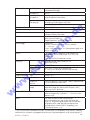
16. Fehler- und Systemmeldungen
Fehlermeldungen der Messung
Err.1
Err.2
Err.3
bei Alarmgrenze 1
Systemfehler
Zur Reparatur einschicken
Messbereich weit über- oder Prüfen: liegt Messwert
unterschritten
im zul. Messbereich des
Sensors?
Anzeigewert nicht
berechenbar
Messbereich oder
Messrange überprüfen
Eingangsgröße überschritten
Messwerte zu instabil
Signalregelung des Gerätes
abwarten
Voreingestellte
Gerät muss kalibriert werden
Kalibrierintervall ist
oder Inaktivierung von c.INT
abgelaufen oder die letzte
= OFF
Kalibrierung war ungültig
sb
-b
Err.7
Gerät defekt
Messbereich ist überschritten Prüfen: liegt Messwert
über zul. Messbereich des
Sensors? -> Messwert ist zu
hoch!
Sensor defekt
Zur Reparatur einschicken
Messbereich ist
Prüfen: liegt Messwert
unterschritten
unter zul. Messbereich des
Sensors? -> Messwert ist
zu tief!
Sensor defekt
Zur Reparatur einschicken
Anzeigebereich
Drücken
überschritten
oder
von
lin
.d
e
Gerät reagiert nicht auf
Tastendruck
Abhilfe
Neue Batterie einsetzen
Batterie und Netzgerät
abklemmen, kurz warten,
wieder anstecken
Zur Reparatur einschicken
er
Keine Anzeige oder wirre
Zeichen
Bedeutung
Batterie ist leer
Systemfehler
---
.s
> CAL <
CAL blinkt in der oberen
Anzeige
Auto
rAnG
w
no LOGG
Fehlermeldungen des automatischen Abgleichs
CAL Err.1
Zellkonstante zu hoch
w
w
Logger konnte nicht
gestartet werden
CAL Err.2
Zellkonstante zu klein
CAL Err.3
Lösung im falschen Bereich
CAL Err.4
Temperatur falsch
Autorange für den
Anzeigebereich ist aktiviert
=> Einstellung im
Konfigurationsmenü
ermittelte Konstante darf
nicht höher als 1,2 . ZellRange sein
ermittelte Konstante darf
nicht kleiner als 0,4 . ZellRange sein
Falscher Zell-Range / falsche
Lösung / weit außerhalb
Toleranz
Außerhalb zulässiger
Temperatur: 0.0 – 34.0 °C
(bzw. 0.0 – 27.0 °C bei 111.8 mS/cm)
Blinkt in der Anzeige „bAt“, so ist die Batterie verbraucht. Für eine kurze Zeit kann noch
weiter gemessen werden. Steht im Display nur „bAt“ ist die Batterie endgültig verbraucht
und muss gewechselt werden. Eine Messung ist nicht mehr möglich.
SD 320_1 03/2013
27
17.Rücksendung und Entsorgung
17.1 Rücksendung
i
Verwenden Sie zur Rücksendung des Geräts, insbesondere wenn es sich um ein
noch funktionierendes Gerät handelt, eine geeignete Transportverpackung. Achten
Sie darauf, dass das Gerät mit ausreichend Dämmmaterial in der Verpackung
geschützt ist.
lin
.d
e
!
Alle Geräte, die an den Hersteller zurückgeliefert werden, müssen frei von
Probenresten und/oder anderen Gefahrstoffen sein. Probenreste am Gehäuse oder
am Sensor können Personen oder Umwelt gefährden.
17.2 Entsorgung
Geben Sie leere Batterien an den dafür vorgesehenen Sammelstellen ab.
Das Gerät darf nicht über die Restmülltonne entsorgt werden. Soll das Gerät entsorgt werden,
senden Sie dieses direkt an uns (ausreichend frankiert). Wir entsorgen das Gerät sachgerecht
und umweltschonend.
Anzahl
Zellkonstante
0,4 … 1,5
Zellkonstante
0,04 … 0,15
Zellkonstante
0,004 … 0,015
0,0 ... 500,0
µS/cm
0,00 ... 50,00
µS/cm
0,000 ... 5,000
µS/cm
sb
-b
Messbereiche
er
18. Technische Daten
Leitfähigkeit 1 *)
2 *)
0 ... 5000
µS/cm
0,0 ... 500,0
µS/cm
0,00 ... 50,00
µS/cm
”
3 *)
0,00 ... 50,00
mS/cm
0 ... 5000
µS/cm
0,0 ... 500,0
µS/cm
.s
”
4 *)
0,0 ... 500,0
mS/cm
0,00 ... 50,00
mS/cm
---
”
5 *)
0 ... 1000 mS/cm
---
---
Spez. Widerstand
0,0010 ... 500,0
kOhm . cm
0,010 ... 5000
kOhm . cm
0,0001 ...
50,00
MOhm . cm
TDS
0,0 ... 5000 mg/l
0,00 ... 5000
mg/l
0,000 ... 5000
mg/l
w
w
w
”
Salinität
0,0 ... 70,0 g/kg (PSU)
Temperatur
-5,0 ... +100,0 °C, Pt1000 oder NTC (10k)
23,0 ... 212,0 °F
Unterstützte Zellkonstanten
28
4,000 … 15,000 / cm; 0,4000 … 1,5000 / cm;
0,04000 … 0,15000 / cm; 0,040000 … 0,015000 / cm;
SD_320_1 03/2013
Genauigkeit
Anschlüsse
Leitfähigkeit
±0,5% v.MW ±0,1 % FS (Systemgenauigkeit
elektrodenabhängig!)
Temperatur
±0,2 K
Leitfähigkeit,
Temperatur
7 poliger Bajonettanschluss zum Anschluss
unterschiedlicher Messzellen
Schnittstelle / ext.
Versorgung
4 polige Bajonettanschluss für ser. Schnittstelle und
Versorgung (USB Adapter USB 300)
Analogausgang 0-1V, einstellbar
4 ½ stellig 7-Segment, beleuchtet (weiß)
Zus Funktionen
Min/Max/Hold
Abgleich
Zellkonstante manuell oder automatisch über
wählbare Referenzlösungen
GLP
einstellbare Abgleichintervalle (1 bis 730 Tage, CALWarnung nach Ablauf)
Abgleichspeicher: letzte 16 Abgleiche
Datenlogger
Echtzeituhr
Zyklisch: 10000 Datensätze, Zyklus wählbar:
1s … 60 min
Einzel: 1000 Datensätze, mit Messtelleneingabe und
Datum + Uhrzeit
er
lin
.d
e
Display
bruchfestes PA6 GB30 Gehäuse, inkl.
Schutzarmierung
Schutzart
IP65 / IP67
Abmessungen
L . B . H [mm]
164 . 128 . 37 inkl. Schutzarmierung,
ca. 250 g inkl. Batterie und Schutzarmierung
.s
Gehäuse
2 Alarmkanäle mit separaten Grenzwerten für
Leitfähigkeit (bzw. Widerstand, TDS, SAL) und
Temperatur
Alarmierung Ton/Visuell/Schnittstelle
sb
-b
Alarm
-25 bis 50 °C; 0 bis 95 % r.F. (nicht betauend)
Lagertemperatur
-25 bis 70 °C
Stromversorgung
2 . AAA-Batterie, (im Lieferumfang) oder extern
w
w
w
Arbeitsbedingungen
Stromaufnahme
6,25 mA (bei Out = Off, entspr. 160 h), Beleuchtung
~10 mA (schaltet autom. ab)
Batterieanzeige
4 stufige Batteriezustandsanzeige,
Wechselanzeige bei verbrauchter Batterie "bAt",
Warnung "bAt“ blinkend
Auto-Off-Funktion
falls aktiviert, schaltet sich das Gerät automatisch ab,
wenn es längere Zeit (wählbar 1 ... 120 min) nicht
bedient wird
EMV
Das Gerät entspricht den wesentlichen
Schutzanforderungen, die in der Richtlinie des
Rates zur Angleichung der Rechtsvorschriften der
Mitgliedsstaaten über die elektromagnetische
Verträglichkeit (2004/108/EG) festgelegt sind.
Zusätzlicher Fehler: <1%
*) Die Auswahl der Elektrode kann den tatsächlichen Einsatzbereich einschränken, obwohl
theoretisch ein weiterer Anzeigebereich durch das Gerät bereitgestellt wird! Siehe Kapitel 6.7
SD 320_1 03/2013
29
Name of the manufacturer:
lin
.d
e
EC Declaration of Conformity
Tintometer GmbH
Schleefstraße 8 - 12
44287 Dortmund
Germany
declares that this product
SD 320 Con
er
Product name:
sb
-b
conforms to the following standards which are specified in the Council Directive for the
harmonisation of legal regulations of the Member States over electromagnetic compatibility
(2004/108/EC) and the Low-Voltage Directive (2006/95/EC).
For the evaluation of the product in regard to electromagnetic compatibility, the following
standards were consulted:
.s
EN 61326-1: 2006 (Table 3, Class B)
EN 61326-1: 2006 (Annex 3, Class B)
w
w
This declaration is issued on behalf of the manufacturer by the responsible person,
w
Dortmund, January 20, 2013
Cay-Peter Voss, Managing Director
Table of contents
GB
32
32
32
32
33
34
34
34
35
35
35
36
36
37
37
37
37
38
39
39
40
40
40
40
41
41
41
42
48
48
49
50
50
51
51
52
53
53
53
54
54
54
55
56
56
56
56
SD 320_1 03/2013
31
w
w
w
.s
sb
-b
er
lin
.d
e
1.
General information. . . . . . . . . . . . . . . . . . . . . . . . . . . . . . . . . . . . . . . . . . . . . . . .
2.Safety. . . . . . . . . . . . . . . . . . . . . . . . . . . . . . . . . . . . . . . . . . . . . . . . . . . . . . . . . . .
2.1 Intended use . . . . . . . . . . . . . . . . . . . . . . . . . . . . . . . . . . . . . . . . . . . . . . . . . . . . .
2.2 Safety signs and symbols . . . . . . . . . . . . . . . . . . . . . . . . . . . . . . . . . . . . . . . . . . . .
2.3 Safety instructions . . . . . . . . . . . . . . . . . . . . . . . . . . . . . . . . . . . . . . . . . . . . . . . . .
Product description. . . . . . . . . . . . . . . . . . . . . . . . . . . . . . . . . . . . . . . . . . . . . . . . .
3.
3.1 Delivery contents . . . . . . . . . . . . . . . . . . . . . . . . . . . . . . . . . . . . . . . . . . . . . . . . . .
3.2 Operating and maintenance information . . . . . . . . . . . . . . . . . . . . . . . . . . . . . . . .
4.Operation. . . . . . . . . . . . . . . . . . . . . . . . . . . . . . . . . . . . . . . . . . . . . . . . . . . . . . . .
4.1 Display elements. . . . . . . . . . . . . . . . . . . . . . . . . . . . . . . . . . . . . . . . . . . . . . . . . . .
4.2Controls. . . . . . . . . . . . . . . . . . . . . . . . . . . . . . . . . . . . . . . . . . . . . . . . . . . . . . . . .
4.3Connections. . . . . . . . . . . . . . . . . . . . . . . . . . . . . . . . . . . . . . . . . . . . . . . . . . . . . .
4.4 Stand/ Mounting . . . . . . . . . . . . . . . . . . . . . . . . . . . . . . . . . . . . . . . . . . . . . . . . . .
5.Set-up . . . . . . . . . . . . . . . . . . . . . . . . . . . . . . . . . . . . . . . . . . . . . . . . . . . . . . . . . .
6.
Measurement principles. . . . . . . . . . . . . . . . . . . . . . . . . . . . . . . . . . . . . . . . . . . . .
6.1 Conductivity principles. . . . . . . . . . . . . . . . . . . . . . . . . . . . . . . . . . . . . . . . . . . . . .
6.2 Measurement ranges and cell constants. . . . . . . . . . . . . . . . . . . . . . . . . . . . . . . . .
6.3 Conductivity measurement. . . . . . . . . . . . . . . . . . . . . . . . . . . . . . . . . . . . . . . . . . .
6.4 Measurement of specific resistance. . . . . . . . . . . . . . . . . . . . . . . . . . . . . . . . . . . . .
6.5 Total Dissolved Solids/ TDS measurement . . . . . . . . . . . . . . . . . . . . . . . . . . . . . . . .
6.6 Salt content measurement/ salinity measurement. . . . . . . . . . . . . . . . . . . . . . . . . .
6.7 Electrodes/ measurement cells . . . . . . . . . . . . . . . . . . . . . . . . . . . . . . . . . . . . . . . .
6.7.1 Bayonet connection assignment. . . . . . . . . . . . . . . . . . . . . . . . . . . . . . . . . . . . . . .
6.7.2 Setup and selection . . . . . . . . . . . . . . . . . . . . . . . . . . . . . . . . . . . . . . . . . . . . . . . .
6.8 Temperature compensation . . . . . . . . . . . . . . . . . . . . . . . . . . . . . . . . . . . . . . . . . .
6.8.1 Temperature compensation "nLF" according to EN 27888 . . . . . . . . . . . . . . . . . . .
6.8.2 Linear temperature compensation and determination
of the temperature coefficient "t.Lin". . . . . . . . . . . . . . . . . . . . . . . . . . . . . . . . . .
Device configuration. . . . . . . . . . . . . . . . . . . . . . . . . . . . . . . . . . . . . . . . . . . . . . . .
7.
8.
Data logger . . . . . . . . . . . . . . . . . . . . . . . . . . . . . . . . . . . . . . . . . . . . . . . . . . . . . .
8.1 Manual storage ("Func-Stor"). . . . . . . . . . . . . . . . . . . . . . . . . . . . . . . . . . . . . . . . .
8.2 Automatic storage with adjustable "Func CYCL" cycle. . . . . . . . . . . . . . . . . . . . . .
9.
Universal output. . . . . . . . . . . . . . . . . . . . . . . . . . . . . . . . . . . . . . . . . . . . . . . . . . .
9.1Interface. . . . . . . . . . . . . . . . . . . . . . . . . . . . . . . . . . . . . . . . . . . . . . . . . . . . . . . . .
9.2 Analogue output . . . . . . . . . . . . . . . . . . . . . . . . . . . . . . . . . . . . . . . . . . . . . . . . . .
10 Adjustment of the device. . . . . . . . . . . . . . . . . . . . . . . . . . . . . . . . . . . . . . . . . . . .
11. Automatic calibration of the cell constant. . . . . . . . . . . . . . . . . . . . . . . . . . . . . . . .
12.GLP . . . . . . . . . . . . . . . . . . . . . . . . . . . . . . . . . . . . . . . . . . . . . . . . . . . . . . . . . . . .
12.1 Calibration interval (C.Int). . . . . . . . . . . . . . . . . . . . . . . . . . . . . . . . . . . . . . . . . . . .
12.2 Calibration data memory (rEAd CAL) . . . . . . . . . . . . . . . . . . . . . . . . . . . . . . . . . . .
13. Alarm ("AL."). . . . . . . . . . . . . . . . . . . . . . . . . . . . . . . . . . . . . . . . . . . . . . . . . . . . .
14. Real time clock ("CLOC"). . . . . . . . . . . . . . . . . . . . . . . . . . . . . . . . . . . . . . . . . . . .
15. Battery replacement. . . . . . . . . . . . . . . . . . . . . . . . . . . . . . . . . . . . . . . . . . . . . . . .
16. Error and system messages. . . . . . . . . . . . . . . . . . . . . . . . . . . . . . . . . . . . . . . . . . .
17. Return and disposal . . . . . . . . . . . . . . . . . . . . . . . . . . . . . . . . . . . . . . . . . . . . . . . .
17.1Return . . . . . . . . . . . . . . . . . . . . . . . . . . . . . . . . . . . . . . . . . . . . . . . . . . . . . . . . . .
17.2Disposal. . . . . . . . . . . . . . . . . . . . . . . . . . . . . . . . . . . . . . . . . . . . . . . . . . . . . . . . .
18. Technical data. . . . . . . . . . . . . . . . . . . . . . . . . . . . . . . . . . . . . . . . . . . . . . . . . . . . .
1. General information
Please read through this document carefully and familiarise yourself with the operation of
the device before you use it. Keep this document to hand and in the immediate vicinity of
the device so that you or skilled personnel can refer to it at all times.
Assembly, set-up, operation, maintenance and decommissioning may only be performed
by specifically qualified personnel. The skilled personnel must have carefully read and
understood the operating manual prior to commencing with any type of work.
lin
.d
e
The liability and warranty of the manufacturer for damages and consequential damages are
void in the event of improper use, non-observance of this operating manual, assignment of
insufficiently qualified skilled personnel and arbitrary modification of the device.
The manufacturer is not liable for costs or damages arising to the user or third parties from
the use of this device, in particular as a result of improper use of the device or misuse or
faults of the connection or the device.
The manufacturer assumes no liability for printing errors.
er
2. Safety
2.1 Intended use
sb
-b
The device is designed for the measurement of conductivity, specific resistance, salt content
and TDS with the use of suitable electrodes (measurement cells). The electrode connection is
made via a 7-pin bayonet connection.
Please observe: Different electrode types may be required depending on the measurement range ensure that you have made the appropriate selection
w
w
.s
It is likewise possible to connect a temperature sensor (Pt1000 or NTC 10k) by means of the
7-pin bayonet connection. Normally a suitable temperature sensor is already integrated in the
electrode. The measured temperature is used by the automatic temperature compensation
(e.g. Lin or nIF) for the measurement and is also displayed.
The safety instructions in this operating manual must be observed (see below).
The device may only be used under the conditions and for the purposes for which it was
designed.
The device must be handled with care and used in accordance with the technical data (do
not drop etc.). Protect from dirt.
2.2 Safety signs and symbols
w
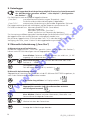
Warning notices are identified in this document as follows:
!
1. Warning! This symbol warns of an immediately threatening danger;
fatality, severe injury and/or extensive property damage may be the
result of non-observance.
2. Attention! This symbol warns of potential dangers or hazardous
situations which may cause damage to the device and/or the environment as a result of non-observance.
i
32
3. Note! This symbol draws your attention to processes which have an
indirect influence on the operation or may trigger an unforeseen
reaction as a result of non-observance.
SD_320_1 03/2013
2.3 Safety instructions
This device is built and tested in accordance with the safety regulations for electronic
measurement devices. The faultless function and operational safety of the device can only be
guaranteed if the applicable safety precautions as well as the device-specific safety instructions
in this manual are observed.
2. !
If it is to be assumed that the device can no longer be operated without potential
danger, it must be decommissioned and corrected by means of identification
prior to re-commissioning. The safety of the user may be diminished by the
device if it
- has visible damage.
- no longer works as prescribed.
- was stored for an extended period of time in unsuitable conditions.
In case of doubt, send the device to the manufacturer for repair or maintenance.
er
lin
.d
e
1. The function and operational safety of the device can only be adhered to under the
climate conditions specified in the chapter "Technical data". If the device is transported
from a cold environment into a warm environment, the formation of condensation
may bring about a fault in the device function. In this case, you must wait until the
device temperature has equalised with the room temperature prior to turning it on.
!
This device is not suitable for safety applications, emergency devices or for use
where malfunction could cause injury and property damage. If this notice is
not observed, severe damage to health and property may occur.
This device may not be used in a potentially explosive environment. In
the event of operation in a potentially explosive environment, there is a
risk of deflagration, fire or explosion due to the formation of sparks.
w
5. !
Do not operate the device with a defective or damaged mains adapter.
Danger of fatality due to electric shock!
.s
4.
sb
-b
3. The instrument should only be connected to external devices with extreme care.
Under certain circumstances, internal connections in third-party devices (e.g. GND
connection with earth) lead to potential impermissible voltage which impairs the
function of the device itself or a connected device, or may even destroy said devices.
w
w
!
SD 320_1 03/2013
33
3. Product description
3.1 Delivery contents
Standard delivery contents include:
- SD 320 Con with 2 AAA batteries
- Electrode
- Operating manual
lin
.d
e
3.2 Operating and maintenance information
1. Battery operation:
If 'bAt' is shown in the lower display, the batteries are depleted and must be replaced. However,
the device function is still assured for a certain amount of time. If 'bAt' is shown in the upper
display, the battery voltage is no longer sufficient for the operation of the device and the battery
is now completely depleted. For battery replacement, see chapter "14. Battery replacement".
If the device is stored at environmental temperatures greater than 50 °C, the batteries
must be removed. If the device is not used for an extended period of time, the
batteries should be removed. However, the clock must be reset after recommissioning.
er
i
2. The device and sensors/electrodes must be handled with care and used in accordance
with the technical data (do not drop etc.). Plug connectors and sockets must be protected
from dirt.
sb
-b
3. USB:
Make sure that only permissible components are connected with a USB interface cable.
w
w
w
.s
4. Operation with the USB 300 interface cable is recommended. If this is used, the device is
supplied with power via the USB interface from the connected PC or USB mains adapter.
34
SD_320_1 03/2013
4. Operation
4.1 Display elements
kΩ•cm MΩ•cm mS µS mg
cm cm l SAL
1
4
°C
MAX
HLD
DIF MIN
5
nLF NaCl
2
°C
°F
Lin
%
K
7
Conductivity (mS/cm, μS/cm)
specific resistance (kΩcm,
MΩcm) TDS, Total Dissolved
Solids (mg/l), salinity (SAL)
2. Secondary display: Temperature measurement value
3. Temperature measurement value
4. Battery status
5. Display elements representing the minimum/
maximum/saved measurement
1 Logg
cm
6
1. Main display: lin
.d
e
3
8
6. nLF NaCl, display of the selected
Temperature compensation
Lin:
7. %/K, 1/cm:
additional
configuration units
er
8. logg-Pfeil:Logger is active.
Arrow blinks: automatic storage
(Logg CYCL) is active.
sb
-b
4.2 Controls
w
w
w
.s
2 Con
On/Off switch, light
Press briefly: Activate light and/or switch
on device
Press and hold: Switch off device
set / menu:
Press briefly: Manual temperature input, if no
temperature sensor is connected.
Press and hold for 2 sec. (Menu): Open the
set-up menu.
min / max:
Press briefly: Display of the minimum and/or
maximum measured value
Press and hold for 2 sec.: Deletion of the respective value
cal: Only in 'cond' operating mode:
Press and hold for 2 sec.: Cell constant calibration
store / enter:
Logger off: Hold and save of the current
measurement ('HLD' in display)
Logger on: Operation of the data logger Data logger chapter
Set/Menu: Confirmation of entries, return to
measurement
SD 320_1 03/2013
35
4.3 Connections
Universal output: Interface, supply, analogue
output (see chapter 9.1, 9.2 Universal output)
4.4 Stand/ Mounting
Operation:
sb
-b
er
Pull
lin
.d
e
7-pin bayonet connection: Connection for
electrode / measuring cell and temperature
sensor
Fold out the stand-up hinge.
w
w
.s
Stand-up hinge folded in. Device can be hung on a belt.
Device set up
on a table.
w
36
Pull out at the
"open" marking to fold
the stand-up hinge out again.
Device hung on
on a screw.
SD_320_1 03/2013
5. Set-up
Connect the electrode, switch on the device with the
button.
he device briefly shows information about its configuration:
After the segment test,
(e.g.
if a zero point or slope correction of the temperature sensor was made (see
chapter 10. Configuration of the device)).
The device is now ready for measurement:
lin
.d
e
6. Measurement principles
6.1 Conductivity principles
Where
l: Length of the material
A: Cross-section
R: Measured resistance
er
Definition of conductivity γ:
The ability of a material to conduct electrical current:
γ = l
(R•A)
sb
-b
[γ] = Siemens = S, common for liquids h:
Unit:
m
metre
Comment
mS and (µS)
cm
cm
1.The conductivity is the reciprocal value of the specific resistance.
2. The conductance is the reciprocal value of the measured resistance R.
3.The cell constant is the ratio of the electrode surface to its distance.
It has the measurement cm-1.
.s
6.2 Measurement ranges and cell constants
w
Various measurement ranges can be realised depending on the selected electrode. There are
4 cell constant ranges which can be adjusted for the various electrodes in the device. These
depend on the corresponding cell constant K:
w
w
CELL rAnG
(Cell constant
range)
0.01
0.1
1
10
Adjustable
cell constant K
Examples for applications
0.004000 - 0.015000•1/cm Purest water, electrodes with K = 0.01
0.04000 - 0.15000•1/cm
Purest water, electrodes with K = 0.1
Standard electrode in the contents of delivery, e.g.
0.4000 - 1.5000•1/cm
SET1 K = 0.55
SET2 K = 0.40
4.000 - 15.000 •1/cm
Electrodes with K = 10 (for extremely high
conductivities)
The cell constant K can be manually entered during configuration (see chapter 7 "Configuration
of the device") or determined with the calibration function. There are therefore two possibilities:
- automatic with reference solutions (temperature compensation)
- adjustment of the displayed value for known solution
SD 320_1 03/2013
37
6.3 Conductivity measurement
The conductivity measurement is a comparatively uncomplicated measurement. When used
properly the standard electrodes are stable for a long time and can be calibrated with the
integrated Cal function.
Attention: The device covers a very wide range of measurements. However a suitable electrode for the measurement range must be used.
1
2
3
0.1
1 (see scope
of delivery)
10
5
0.000 5.000 µS/cm
0.00 - 50.00
µS/cm
0.0 - 500.0
µS/cm
0.00 - 50.00
µS/cm
0.0 - 500.0
µS/cm
0 - 5000
µS/cm
0.0 - 500.0
µS/cm
0 - 5000
µS/cm
0.00 - 50.00
mS/cm
0 - 5000
µS/cm
0.00 - 50.00
mS/cm
0.0 - 500.0
mS/cm
0.00 - 50.00
mS/cm
0.0 - 500.0
mS/cm
0 - 1000
mS/cm
0 - 5000
µS/cm
0.00 - 50.00
mS/cm
0.0 - 500.0
mS/cm
0 - 1000
mS/cm
---
er
0.01
4
lin
.d
e
Range
CELL
- rAnG
w
w
w
.s
sb
-b
If the range selection is set to "Auto Range", the range with the best resolution is automatically selected. However the logger or interface operation requires a fixed pre-selection of the
measurement range from the above table (no logger/interface operation with Auto Range!).
38
SD_320_1 03/2013
6.4Measurement of specific resistance
0.01
0.10 - 50.00
kOhm•cm
0.1
0.010
- 5.000
kOhm•cm
1 (see scope 0.0010
of delivery) - 0.5000
kOhm•cm
10
---
2
0.1 - 500.0
kOhm•cm
0.01 - 50.00
kOhm•cm
0.001
- 5.000
kOhm•cm
0.0001
- 0.5000
kOhm•cm
3
4
0.000
- 5.000
MOhm•cm
0.0 - 500.0
kOhm•cm
5
0.000
- 50.00
MOhm•cm
0.000
- 5.000
MOhm•cm
0.0 - 500.0
kOhm•cm
0.00 - 50.00
mS/cm
0.00 - 50.00
kOhm•cm
---
0.0 - 500.0
mS/cm
lin
.d
e
1
Range
CELL
- rAnG
0.00 - 50.00
kOhm•cm
0.000
- 5.000
kOhm•cm
0 - 1000
mS/cm
er
If the range selection is set to "Auto Range", the range with the best resolution is automatically selected. However the logger or interface operation requires a fixed pre-selection of the
measurement range from the above table (no logger/interface operation with Auto Range!)
sb
-b
6.5 Total Dissolved Solids/ TDS measurement
The total dissolved solids (evaporation residue) are determined with the TDS measurement (Total
Dissolved Solids) based on the conductivity and a conversion factor (C.tdS). The measurement
is therefore well-suited for performing simple concentration measurements of salt solutions,
etc. Values are displayed in mg/l.
1
.s
Range
CELL
- rAnG
0.01
0.1
1 (see scope
of delivery)
10
2
3
4
0.00 - 50.00 mg/l 0.0 - 500.0 mg/l 0 - 5000 mg/l
0.0 - 500.0 mg/l 0 - 5000 mg/l
--0 - 5000 mg/l
-----
0 - 5000 mg/l
---
---
---
w
w
w
0.000 - 5.000 mg/l
0.00 - 50.00 mg/l
0.0 - 500.0 mg/l
TDS display value = conductivity [in μs/cm, nLF temperature comp. to 25 °C] • C.tdS
(menu entry). Approximate values:
C.tdS
0.50
0.50
0.65 - 0.70
Monovalent salt with 2 ion types (NaCl, KCL, etc.)
Natural water/surface water, drinking water
e.g. salt concentration of aqueous fertiliser solutions
Attention: These are only reference values and thus well-suited for estimates (not precise
measurements). For precise measurements the conversion factor for the respective type of
solution and the concentration range must be determined.
This can be accomplished with calibration to known comparison solutions or through actual
evaporation of a specific quantity of liquid with measured conductivity and subsequent
weighing of the dry residue.
SD 320_1 03/2013
39
6.6 Salt content measurement/ salinity measurement
In the measurement mode "SAL", the salinity (salt content) of seawater can be determined
(ref: International Oceanographic Tables; IOT). Standard seawater has a salinity of 35 ‰ (35
g salt per 1 kg seawater).
The display normally is normally shown in ‰ (g/kg) without units.
Similarly useful is the identifier "PSU" (Practical Salinity Unit); the display for this is identical.
The salinity measurement has automatic temperature compensation, which may cause some
menu settings to be ignored.
lin
.d
e
Attention: The salt composition of different seas is not identical. Considerable deviations
from the 35 ‰ according to IOT arise due to location, weather, tides, etc. The salt
composition can also influence the relationship of the salinity display to the actual salt
quantity present.
6.7Electrodes/ measurement cells
er
Corresponding tables are available for many salts in seawater aquariums (salt weight
to salinity according to IOT and/or conductivity). Precise salinity measurements can
be performed in consideration of these tables (we recommend graphite 4-pole
measurement cells LC 12 or LC 16).
6.7.1 Bayonet connection assignment
.s
1: Electrode I+
2: Electrode U+
3: Electrode U4: Electrode I5: Temperature sensor
6: Temperature sensor
7: not assigned
w
sb
-b
Device connection
6.7.2 Setup and selection
w
w
As a basic rule, there are two different types of measurement cells: 2-pole and 4-pole measurement cells. The control and/or evaluation takes place in a similar manner. The 4-pole measurement cells can compensate for polarisation effects and contamination to a certain degree.
40
2-pole measurement cell 4-pole measurement cell
SD_320_1 03/2013
The selection of the appropriate electrode depends on the application case
•The graphite 4-pole measurement cells (LC 12 or LC 16, for all previously mentioned applications and: seawater, titration, waste water) offer the broadest application spectrum.
•For low conductivities (<100 μS/cm), stainless steel cells are beneficial (rain and purest
water, boiler water, osmosis and filter technology).
6.8 Temperature compensation
lin
.d
e
•For low conductivities (<1000 μS/cm), platinum electrodes with glass shaft are beneficial
(petrol, diesel)
The conductivity of aqueous solutions depends on the temperature. The temperature dependence is heavily dependent of the type of solution. With temperature compensation,
measurements are expressed at a uniform reference temperature. The usual reference temperature for this purpose is 25 °C.
6.8.1 Temperature compensation "nLF" according to EN 27888
er
For most applications, e.g. in the area of fish breeding and the measurement of above-ground
water and drinking water, the non-linear temperature compensation for natural water ("nLF",
according to EN 27888) is sufficient. The usual reference temperature is 25 °C.
The recommended usage range of the nLF compensation: between 60 μS/cm and 1000 μS/cm.
sb
-b
6.8.2 Linear temperature compensation and determination of the
temperature coefficient "t.Lin"
If the function of the temperature compensation is not precisely known, a "linear temperature
compensation" is normally adjusted in the device (menu, t.Cor = Lin, t.Lin corresponding to
TKlin). In simplified terms, that means that the temperature dependence is approximately the
same over the concentration range in consideration for the solution.
w
.s
=
LFTX
LF
Tref
TKlin
1+
• (Tx-Tref)
(100%)
w
w
Temperature coefficients around 2.0 %/K are most common.
A temperature coefficient can be determined, for example, by measuring a solution with
temperature compensation switched off for 2 temperatures (T1 and T2).
LFTref= (LFT1-LFT2) • 100%
(T1-T2) • LFT1
TKlin is the value entered in the menu "t.Lin".
LFT1 conductivity at temperature T1.
LFT2 conductivity at temperature T2.
SD 320_1 03/2013
41
7. Device configuration
i
Some menu items are only accessible depending on the current device setting (e.g.
some are locked when they contain logger data).
Press and hold "menu" for two seconds for the configuration, where the menu
("SEt" main menu) is opened.
lin
.d
e
Select the desired menu branch with „menu“.
Jump to the corresponding parameters which you can then change.
Selection of parameters
Close the configuration.
er
Press again to switch back to the main menu and save the settings.
If the buttons "menu" and "store" are simultaneously pressed and held for longer
than two seconds, the device is reset to the factory settings If data in the
single value logger (Logger: "Func Stor) is first shown as "rEAd Logg" menu:
see also Chapter 8 Data logger for this purpose. If no button is pressed for
a period of more than two minutes, the configuration is cancelled. No changes made
up to that point are saved!
w
w
w
.s
sb
-b
i
42
SD_320_1 03/2013
Menu
Parameter
Values
Meaning
rEAd Logg: Review stored measurements,
see Chapter 8.1! Manual recording ("Func-Stor")
Set Configuration: General settings
Cond
Conductivity
rES:
Specific resistance
SAL
Salt content/salinity
TDS
Total Dissolved Solids
TDS measurement: Conversion factor
(only with Inp = TDS)
0.40 - 1.00
**
lin
.d
e
Input: Selection of the measurement
.
Conversion factor for TDS measurement
0.01
Purest water, electrodes with K ~ 0.01
Purest water, electrodes with K ~ 0.1
w
w
w
.s
sb
-b
0.1
er
Cell Range: Adjustment of the cell constant: Cell
constant range
1
Standard electrode in the standard delivery
contents, e.g.
SET1 K = 0.55
SET2 K = 0.40
10
Electrode with K=10
Cell Factor: Adjustment of the cell constant:
Multiplication factor
0.3800 1.5000
Multiplication factor of the cell constant:
Cell constant CELL = CELL Range . CELL
Factor
t-Input: Selection of the temperature input
NTC
NTC 10k sensor (LC 12)
Pt
Pt1000 sensor (LC 16)
Range: Selection of the display range (conductivity,
spec. resistance or TDS)
Auto
Automatic range selection
e.g.
0.0 ... 500.0
µS/cm
Example for CELL rAng 1 and InP Cond:
for others, see chap. 6.3 - 6.5
...
0 - 1000 mS/cm
SD 320_1 03/2013
Example for CELL rAng 1 and InP Cond:
for others, see chap. 6.3 - 6.5
43
Menu
Parameter
Values
Meaning
Automatic adjustment with reference solutions "CAL" **
only with Input = cond)
Edit
Manual adjustment to reference value
REF.S
Selection from standard reference solutions
lin
.d
e
REF.S: Selection from standard reference solutions for
automatic adjustment. Only with
1413 µS/cm
Reference solution 00:01 M KCL
2760 µS/cm
0.02 M KCL
12.88 mS/cm
0.1 M KCL
50 mS/cm
Sea water comparison solution KCL
111.8 mS/cm
1 M KCL
°C
All temperatures specified in degrees
Celsius
All temperatures specified in degrees
Fahrenheit
sb
-b
°F
er
Unit t: Selection of the temperature unit
Temperature compensation (not with INP = SAL and
TDS)
Do not compensate for conductivity
measurement
nLF
Non-linear function for natural water
according to EN 27888 (DIN 38404)
ground, surface or drinking water
w
w
w
.s
oFF
NaCl
Compensation for NaCl solutions (pure
and purest water)
Lin
Linear temperature compensation
Compensation coefficient (only with t.Cor = Lin) (not
with INP = SAL and TDS)
0.300 - 3.000
Temperature compensation coefficient
in %/K.
Reference temperature of the temperature compensation (not with INP = SAL and TDS)
25 °C / 77 °F
Reference temperature 25 °C / 77 °F
20 °C / 68 °F
Reference temperature 20 °C / 68 °F
Comparison: Time interval for the calibration memory
(factory setting: OFF)
44
1 - 730
Time interval for calibration memory
(in days)
oFF
No calibration memory
SD_320_1 03/2013
Menü
Parameter
Werte
Bedeutung
Auto Hold: Automatic measurement processing (only
with Logger = oFF operative)
Automatic measurement processing
(only with Logger = oFF) Auto Hold
oFF
Standard hold function at the push of a
button (only with Logger = oFF)
lin
.d
e
on
Auto Power-Off : Automatic device shut-off.
Shut-off delay in minutes. If no button is
pressed and data traffic no longer takes
place through the interface, the device
shuts off automatically after the lapse
of this time
oFF
Automatic shut-off deactivated (continuous operation)
er
1 - 120
Background lighting
oFF
No lighting
Automatic shut-off of lighting after 5 120 s (factory setting: 5 s)
on
Lighting always on
sb
-b
5 - 120
Universal output
SEr
Serial interface activated
dAC
Analogue output activated
oFF
Interface and analogue output off ->
minimal power consumption
SD 320_1 03/2013
=
Serial interface (only with
01.11 - 91
Analogue output (only with
w
w
w
.s
)
Base address of the unit for serial interface communication
=
)
0.0000 µS/cm
... 1000 mS/cm
Input of the measurement at which the
analogue output should output 0V, e.g.
with 0.0000 µS/cm
0.0000 µS/cm
... 1000 mS/cm
Input of the measurement at which the
analogue output should output 1V, e.g.
with 100.0 mS/cm
45
lin
.d
e
er
sb
-b
.s
w
w
w
46
SD_320_1 03/2013
Set Corr: Adjustment of the measurements
Zero correction/offset of the temperature
measurement
No zero correction of the temperature
measurement
-5.0 5.0 %
Zero correction of the temperature
measurement in °C
**
lin
.d
e
oFF
**
Slope adjustment of the temperature measurement
oFF
No pitch correction of the temperature
measurement
-5.0 5.0 %
Pitch correction of the temperature
measurement in %
**
Set Alarm: Adjustment of the alarm function
No.So
Measurement channel cond/rES/TDS/
SAL: Alarm on without sound
No alarm function for measurement
channel cond/rES/TDS/SAL
sb
-b
OFF
Measurement channel cond/rES/TDS/
SAL: Alarm on with sound
er
On
0.0000 µS/cm Min. alarm limit cond/rES/TDS/SAL (not
... 1000 mS/cm with AL. 1. oFF)
w
w
w
.s
0.0000 µS/cm Max. alarm limit cond/rES/TDS/SAL (not
... 1000 mS/cm with AL. 1. oFF)
Menu
Parameter
SD 320_1 03/2013
On
Alarm temperature measurement on
with sound
No.So
Alarm temperature measurement alarm
on without sound
OFF
No alarm function for temperature
measurement
-5.0 +100.0 °C
Temperature min. alarm threshold (not
with Al. 2. oFF)
-5.0 +100.0 °C
Temperature max. alarm threshold (not
with Al. 2. oFF)
Values
Meaning
47
8. Data logger
lin
.d
e
Logger operation not possible with Auto-Range! The measurement range
must be pre-selected prior to operation – see chapter 7 "Configuration of the device" The device has two different logger functions:
„Func-Stor“: Manual measurement recording at the push of the "store" button
In addition, a measurement entry (L-Id) is requested.
„Func-CYCL“: Automatic cyclical recording in the adjusted time interval
The logger records the conductivity and the temperature for each data set.
A data set is comprised of: Measurement cond/rES/TDS/SAL (one of these)
Temperature measurement value
L-ID measurement point (only with "Func-Stor")
Time and date at which the data is saved
For the evaluation and transmission of the data, the software GSOFT3050 (V3.0 or later) is
required. It can be used to start and adjust the logger function very simply.
With the logger function activated (Func Stor of Func CYCL), the hold function is not available;
in this case the "store" button is responsible for the logger operation.
8.1 Manual storage ("Func-Stor")
Press briefly: Data set is saved ("St. XX" is briefly displayed. XX is the number of the data set.)
or
sb
-b
er
a) Record measurements manually:
If the "Func Stor" logger function was selected (see "Configuration of the device"),
up to 1000 measurements can be saved manually:
The entry is confirmed.
If the logger memory is full, the following appears
.s
measurement point input "L-Id": Selection of the measurement point
with keys. Number from 0 - 19999.
w
b) Call up manual recording:
Saved data sets can be read in the GSOFT3050 software and can be observed in the device
display itself.
Press for two seconds: The following appears in the display:
w
"rEAd LoGG" only appears if the data sets have already
been saved! Without data sets, the configuration menu appears Press briefly: Switch between measurement values, measurement point
and date+time display of the data set
w
i
or
Switch between the calibration data sets.
Close the display of the records.
48
SD_320_1 03/2013
c) Delete manual recording:
If data is already saved, it can be deleted with the store button:
Press and hold for two seconds: Open the delete menu
or
Switch the selection
lin
.d
e
Delete nothing (cancel the process)
Delete all data sets
Delete the most recently saved data set
Confirmation of the selection, end of the delete menu
er
8.2 Automatic storage with adjustable cycle "Func CYCL"
sb
-b
If the "Func CYCL" logger function is selected (see "Device configuration"),
measurements are automatically recorded at the pre-selected time interval. The
logger cycle time is adjustable from 1 s to 60 min (see "Device configuration").
Recordable data sets: 10000. The automatically recorded values can only be displayed on
the PC.
a) Start logger recording:
Press and hold for two seconds: Start selection
.s
w
w
w
Then press again: automatic recording is started. Each save process is
signalled by a brief display of "St.XXXXX". XXXXX stands for the
number of the data set.
If the logger memory is full, the recording is automatically stopped.
b) Stop logger recording:
Press and hold for two seconds: : If a recording is in progress, the
stop menu appears
or
Switch the selection
Do not stop the recording (cancel process)
Stop recording
Confirmation of the selection, end of the delete menu
SD 320_1 03/2013
49
i
If a cyclical recording attempt is made with the device running, a query of whether
the recording should be stopped automatically appears.
The device can only be switched off if the recording is stopped.
The Auto Power Off function is deactivated when a recording is in progress!
c) Delete logger recording:
Press and hold for two seconds: Start menu "
or
:
Switch the selection:
or
: Confirm with
Delete nothing (cancel the process)
Delete all data sets
.
.
sb
-b
: Confirm with
er
lin
.d
e
Switch the selection:
" appears.
Delete the most recently saved data set
Confirmation of the selection, end of the delete menu
.s
9. Universal output
w
The output can be used either as a serial interface (for USB 300 interface adapter) or as an
analogue output (0-1V). If the output is not required, it should be deactivated (Out oFF),
because the battery consumption is sharply reduced as a result.
If the device is operated with the USB 300 universal interface adapter, the device is powered
by this interface.
w
w
Plug assignment:
4: external supply +5V, 50mA
3: GND
2: TxD/RxD (3.3V logic)
1: +UDAC, analogue output
Only suitable adapter cables
are permitted
(Accessories)
9.1 Interface
With a USB 300 galvanically isolated interface converter (accessory), the device can be connected directly to a USB interface of a PC. The transmission takes place coded in binary format
and is protected against transmission errors through extensive safety mechanisms (CRC).
The following standard software package is available:
GSOFT3050: Operating and evaluation software for the integrated logger function
50
SD_320_1 03/2013
i
The measurement/alarm/range values output through the interface are always output in the adjusted display unit!
Attention: To use the interface functions, the auto-range function should
be switched off.
9.2Analogue output
lin
.d
e
An analogue voltage of 0-1 V can be tapped at the universal output jack (Out dAC setting).
With DAC.0 and DAC.1 the analogue output can be scaled very easily.
It must be ensured that the analogue output is not too heavily stressed, otherwise the output
value can be falsified and the power consumption of the device increases sharply. Loads of
up to approx. 10kOhm are harmless.
If the display exceeds the value adjusted with DAC.1, 1V is output.
If the display undercuts the value adjusted with DAC.1, 0V is output.
In the event of an error (Err.1, Err.1, etc.), a voltage slightly above 1V is output at the analogue output.
10. Adjusting the temperature input
sb
-b
er
With offset and scale, the measurement inputs can be adjusted, both for the voltage measurement and the temperature measurement. Requirement: Reliable references are available
(e.g. ice water, regulated precision water baths, etc.):
If an adjustment is made (deviation from factory setting), this is signalled with the message
"Corr" when the device is switched on.
Standard setting of the zero point and slope values is: "off" = 0.0, which means no correction has been made.
Only offset correction:
Offset = measured value – setpoint
w
.s
Offset and slope adjustment:
Setpoint = (measured value – OFFS) . (1 + SCAL / 100)
Setpoint
SCAL = Measured value - OFFS . 100 -100
(Display °F =(measured value °F - 32°F - OFFS) . (1 + SCAL / 100 ))
w
w
SD 320_1 03/2013
51
11Automatic calibration of the cell constant
In addition to the direct input of the cell constant (see below) through the menu ("CELL
FACt"), the cell constant can also be automatically determined (please define CELL rAnG in
the menu first):
Menu selection:
Manual adjustment:
or "CAL Edit"
er
lin
.d
e
Calibration with reference
solutions
"CAL rEF.S"
Menu selection of the desired
solution
1413 µS/cm 0.01 M KCL
2.76 mS/cm 0.02 M KCL
12.88 mS/cm 0.1 M KCL
50 mS/cm
KCL
111.8 mS/cm 1 M KCL
Specifications at 25 °C. The
temperature variations of the
indicated solutions are recorded in
the device and are automatically
compensated for.
Press the Cal button
"Current value" e.g. "1823
"Solution value" e.g. "1413 µS/cm"
for 2s,
µS/cm" and CAL with rotating and CAL with rotating symbol
Start of the calibration: symbol
Wait until the device detects a stable
value
sb
-b
Calibration
With the
or
buttons, adjust the
setpoint
Confirm with "enter"
w
.s
Then the device returns to normal measurement mode or, if applicable, returns an error
message. The resulting cell constant can be viewed in the menu under "CELL rAng" and in
the calibration history.
Error messages of the automatic calibration:
Cell constant too high
Determined constant may
not exceed 1.5 . cell range
Cell constant too low
Determined constant may
not be below 0.4 . cell
range
CAL Err.3
Solution in the incorrect
range
Incorrect cell range /
incorrect solution / far
outside of tolerance
CAL Err.4
Temperature incorrect
Outside of permissible
temperature range: 0.0 –
34.0 °C
(or 0.0 – 27.0 °C at 111.8
mS/cm)
w
CAL Err.1
w
CAL Err.2
52
SD_320_1 03/2013
Alternative to automatic calibration:
Manual determination of cell constant with a reference solution
Example with KCI solution c = 0.01 M: 1413 µS cm-1 at 25°C
Switch off the temperature compensation (t.Cor = oFF) for other temperatures and use the
corresponding setpoint for the temperature!
ConductivityDisplay = 1900 μS cm-1 with adjusted cell constant of 1.000 cm-1 (CELL FACt 1.000)
specific conductivity of the solution at 25°C: Conductivity Setpoint = 1413 μS cm-1
12. GLP
lin
.d
e
Cell constant k = Conductivity Setpoint / Conductivity Display [cm-1]
= 1413 / 1900 μS cm-1 = 0.7437 cm-1 (adjust CELL FACT to 0.7437)
The regular monitoring of the device and accessories is a part of the GLP (Good Laboratory
Practice). With conductivity measurements, the correct pH calibration, in particular, must be
assured. To enable this, the device assists you with functions mentioned below.
A prerequisite for the use of the GLP functions is that the electrode is not replaced. The data
is saved in the device. However, it is based on the respective electrode.
12.1 Calibration interval (C.Int)
sb
-b
er
You can specify a fixed interval at which you automatically remind the device that a new
calibration should be performed and/or that the calibration is no longer valid.
The length of the interval depends on your use and the stability of the electrode. As soon as
the interval has lapsed, "CAL" blinks in the display.
12.2 Calibration data storage (rEAd CAL)
The last 16 calibrations with date and results are stored in the device and can be recalled.
Display the calibration data memory:
Saved calibration data can be read in the GSOFT3050 software and can be observed in the
device display itself:
Press and hold for two seconds:
The following appears in the display
Press until the following appears:
w
.s
or
(configuration level)
read cal. = "Read calibration data"
w
w
Press briefly: Switch between
-CELL = cell constant
-C.rEF = reference value against which the cell constant was calibrated
-Date+time display of the data set
or
SD 320_1 03/2013
Switch between the calibration data sets
Close the display of the calibration data sets
53
13. Alarm ("AL.")
14. Real time clock ("CLOC")
lin
.d
e
There are three possible settings:
Off (AL.oFF), On with sound (Al.on), On without sound (AL.no.So).
In the following cases, an alarm is issued when the alarm function is active (on or no.So.):
- Lower alarm threshold (Al. Lo) exceeded.
- Upper alarm threshold (Al. Hi) exceeded.
- Sensor error
- Low battery (bAt)
- Err.7: System error (is always signalled with sound)
In the event of an alarm, the "PRIO" flag is marked in the device response with interface
accesses.
The real time clock is required for the temporal assignment of the logger data and the calibration time point. Therefore, check the settings as necessary.
15. Battery replacement
w
w
w
.s
sb
-b
er
Before replacing the battery, read the following instructions and follow them step by step.
Non-observance can result in damage to the device or may impair the waterproofing of the
device!
Unnecessary adjustment to the screws must be avoided!
1. Release the screws of the protective casing and
remove it.
2. Position the still-closed device so that the
display remains visible. The lower section of
the device, including electronic components,
should remain in this position during the entire
battery replacement.
This prevents the three seal rings in the screw
holes from falling out.
3. Lift off the upper housing half. In the process,
pay special attention to the six function
keys to ensure that they are not damaged.
4. Carefully replace the two batteries (type: AAA).
5. Check: Are all seal rings in the lower section
present (3 units)? Is the surrounding seal
in the upper section undamaged and clean?
6. Fit the upper section on again. Then press
the two housing parts together, place
the device on the display side and screw
it back together. Only tighten the screws
up to the pressure point – additional
tightening does not create a greater
tightness!
54
SD_320_1 03/2013
16. Error and system messages
Error messages for the measurement
No display or confused
symbols
Device does not react to
pushing buttons
Meaning
Battery is depleted
System error
Recommendation
Insert new battery
Disconnect battery and
mains adapter, wait a short
time and plug in again
Send in for repair
Device defective
Err.1
Sensor defect
Measurement range
undercut
Sensor defect
Display range exceeded
of
System error
Results significantly outside
detection range
sb
-b
Err.3
at alarm threshold 1
er
Err.2
Err.7
Check: Is the measurement
above the permissible
measurement range of the
sensor? -> Measurement
value is too high!
Send in for repair
Check: Is the measurement
below the permissible
measurement range of the
sensor? -> Measurement
value is too low!
Send in for repair
Pressing
lin
.d
e
Below measurement range
or
Send in for repair
Check: Is the measurement
within the permissible
measurement range of the
sensor?
Display value not calculable
---
.s
> CAL <
CAL blinks in the upper
display
Auto
rAnG
The pre-adjusted calibration
interval has lapsed or the
last calibration was invalid
The device must be
calibrated or inactivation of
c.INT = OFF
Logger could not be started
Autorange for the display
range is activated
=> Setting in the
configuration menu
w
no LOGG
Measurement range or input Check measurement range
parameter exceeded
Measurements too unstable Wait for reading to stabilize
w
w
Error messages of the automatic calibration
CAL Err.1
Cell constant too high
CAL Err.2
Cell constant too low
CAL Err.3
Solution in the incorrect
range
CAL Err.4
Temperature incorrect
Determined constant may
not exceed 1.2 . cell range
Determined constant may
not be below 0.4 . cell range
Incorrect cell range /
incorrect solution / far
outside of tolerance
Outside of permissible
temperature range: 0.0 –
34.0 °C (or 0.0 – 27.0 °C at
111.8 mS/cm)
If "bAt" blinks in the display, the battery is very low. Measurement can continue for a brief
time. If "bAt" remains in the display, the battery is fully depleted and must be replaced. No
more measurements can take place.
SD 320_1 03/2013
55
17.Return and disposal
17.1 Return
i
Use suitable transport packaging for the return of the device, especially if it is still a
functioning device. Make sure that the device is protected with sufficient insulating
material in the packaging.
lin
.d
e
!
All devices which are sent back to the manufacturer must be free from sample
remains and/or other harmful substances. Sample remains on the housing or on
the sensor can endanger persons or the environment.
17.2 Disposal
Drop off the depleted batteries at a collection centre designated for this purpose.
The device may not be disposed of with the household waste. If the device needs to be
disposed of, send it directly to us (with sufficient postage paid). We will dispose of the device
properly and in an environmentally friendly manner.
Number
Cell constant
0.4 - 1.5
Cell constant
0.04 - 0.15
Cell constant
0.004 - 0.015
0.0 - 500.0
µS/cm
0.00 - 50.00
µS/cm
0.000 - 5.000
µS/cm
sb
-b
Measurement
ranges
er
18. Technical data
Conductivity 1 *)
2 *)
0 - 5000
µS/cm
0.0 - 500.0
µS/cm
0.00 - 50.00
µS/cm
"
3 *)
0.00 - 50.00
mS/cm
0 - 5000
µS/cm
0.0 - 500.0 µS/
cm
"
4 *)
0.0 - 500.0
mS/cm
0.00 - 50.00
mS/cm
---
"
5 *)
.s
"
---
---
0.0010 - 500.0
kOhm . cm
0.010 - 5000
kOhm . cm
0.0001 - 50.00
MOhm . cm
TDS
0.0 - 5000 mg/l
0.00 - 5000
mg/l
0.000 - 5000
mg/l
w
w
w
0 - 1000 mS/cm
Spec. resistance
Salinity
0.0 - 70.0 g/kg (PSU)
Temperature
-5.0 - +100.0 °C, Pt1000 or NTC (10k)
23.0 ... 212.0 °F
Supported cell constants
4.000 - 15.000 / cm; 0.4000 - 1.5000 / cm;
0,04000 … 0,15000 / cm; 0,040000 … 0,015000 / cm;
Connections
Conductivity,
temperature
7-pin bayonet connection for the connection of
various measurement cells
Interface / ext.
supply
4-pin bayonet connection for ser. interface and supply
(USB adapter USB 300)
Analogue output 0-1V, adjustable
Display
56
4 ½ digit, 7-segment, illuminated (white)
SD_320_1 03/2013
Min/Max/Hold
Calibration
of cell constants manually or automatically using
selectable reference solutions
GLP
Adjustable calibration intervals (1 to 730 days, CAL
warning after lapse)
Calibration memory: lasts 16 calibrations
Data logger
Real time clock
Cyclical: 10.000 data sets, variable cycle:
1s - 60 min
Single: 1000 data sets, with measurement point entry
and date + time
Alarm
2 alarm channels with separate thresholds for
conductivity (and/or resistance, TDS, SAL) and
temperature
Alarm audio/visual/interface
Housing
Break-proof PA6 GB30 housing, incl. protective
reinforcement
IP65 / IP67
Dimensions
L x W x H [mm]
164 x 128 x 37 incl. protective reinforcement,
approx. 250 g incl. battery and protective
reinforcement
-25 to 70 °C
2 . AAA batteries, (included in the scope of delivery)
or external
power consumption
6.25 mA (with Out = Off, corresponding to 160 h),
lighting ~10 mA (switches off automatically)
Battery display
4-stage battery status display,
Change display with depleted battery "bAt"; "bAt"
blinking = warning
If activated, the device switches off automatically
when not used for an extended period of time
(variable 1 - 120 min)
EMC
The device corresponds to the essential safety
requirements, which are defined in the Council
Directive for the harmonisation of the legal
requirements of the Member States over
electromagnetic compatibility (2004/108/EC).
Additional error: <1%
w
.s
Auto-Off function
w
w
-25 to 50 °C; 0 to 95 % r.h. (non condensing)
sb
-b
Storage temperature
er
Protection class
Operating conditions
Power supply
lin
.d
e
Add. functions
*)The selection of the electrode can diminish the actual range of application, although
additional display range is theoretically provided by the device. See Chapter 6.7
SD 320_1 03/2013
57
lin
.d
e
er
sb
-b
.s
w
w
w
58
SD_320_1 03/2013
w
.s
w
w
er
sb
-b
lin
.d
e
lin
.d
e
er
sb
-b
The Tintometer Limited
Lovibond House / Solar Way
Solstice Park / Amesbury, SP4 7SZ
Tel.: +44 (0)1980 664800
Fax: +44 (0)1980 625412
[email protected]
www.lovibond.com
Tintometer AG
Hauptstraße 2
5212 Hausen AG
Tel.: +41 (0)56/4422829
Fax: +41 (0)56/4424121
[email protected]
www.tintometer.ch
UK
Schweiz
w
w
w
.s
Tintometer GmbH
Lovibond® Water Testing
Schleefstraße 8-12
44287 Dortmund
Tel.: +49 (0)231/94510-0
Fax: +49 (0)231/94510-30
[email protected]
www.lovibond.com
Deutschland
Technische Änderungen vorbehalten
Printed in Germany 09/13
No.: 19805021
Lovibond® und Tintometer®
sind eingetragene Warenzeichen
der Tintometer Firmengruppe
Tintometer South East Asia
Unit B-3-12, BBT One Boulevard,
Lebuh Nilam 2, Bandar Bukit Tinggi,
Klang, 41200, Selangor D.E
Tel.: +60 (0)3 3325 2285/6
Fax: +60 (0)3 3325 2287
[email protected]
www.lovibond.com
Malaysia