1
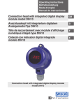
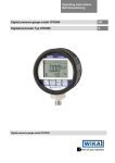
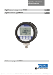
Operating instructions
Betriebsanleitung
Connection head with integrated digital display
module in accordance with ATEX directive
Model DIH10-Ex
Anschlusskopf mit integriertem digitalem
Anzeigemodul nach ATEX-Richtlinie
Typ DIH10-Ex
Connection head with integrated digital display module
model DIH10-Ex
GB
D
GB Operating instructions model DIH10-Ex
D Betriebsanleitung Typ DIH10-Ex
Page 3 - 30
Seite 31 - 57
Further languages can be found at www.wika.com.
© 2014 WIKA Alexander Wiegand SE & Co. KG
All rights reserved. / Alle Rechte vorbehalten.
WIKA® is a registered trademark in various countries.
WIKA® ist eine geschützte Marke in verschiedenen Ländern.
Vor Beginn aller Arbeiten Betriebsanleitung lesen!
Zum späteren Gebrauch aufbewahren!
2
WIKA operating instructions model DIH10-Ex
3330872.01 02/2014 GB/D
Prior to starting any work, read the operating instructions!
Keep for later use!
Contents
Contents
1. General information
2. Safety
3. Specifications
4. Design and function
5. Transport, packaging and storage
6. Commissioning, operation
7. Information on mounting and operation in
hazardous areas
8. Maintenance and cleaning
GB
4
6
12
14
17
18
23
25
9. Faults
26
Appendix: EC declaration of conformity
29
10. Dismounting, return and disposal
27
3330872.01 02/2014 GB/D
Declarations of conformity can be found online at www.wika.com.
WIKA operating instructions model DIH10-Ex
3
1. General information
1. General information
■■ The instrument described in these operating instructions has been
designed and manufactured using state-of-the-art technology. All
components are subject to stringent quality and environmental
criteria during production. Our management systems are certified to
ISO 9001 and ISO 14001.
■■ These operating instructions contain important information on
handling the instrument. Working safely requires that all safety
instructions and work instructions are observed.
■■ Observe the relevant local accident prevention regulations and
general safety regulations for the instrument's range of use.
■■ The operating instructions are part of the product and must be kept
in the immediate vicinity of the instrument and readily accessible to
skilled personnel at any time.
■■ Skilled personnel must have carefully read and understood the
operating instructions prior to beginning any work.
■■ The manufacturer's liability is void in the case of any damage
caused by using the product contrary to its intended use,
non-compliance with these operating instructions, assignment
of insufficiently qualified skilled personnel or unauthorised
modifications to the instrument.
■■ The general terms and conditions contained in the sales
documentation shall apply.
■■ Subject to technical modifications.
■■ Further information:
- Internet address:
- Relevant data sheet:
- Application consultant:
4
www.wika.de / www.wika.com
AC 80.11
Tel.: +49 9372 132-0
Fax: +49 9372 132-406
[email protected]
WIKA operating instructions model DIH10-Ex
3330872.01 02/2014 GB/D
GB
1. General information
Explanation of symbols
WARNING!
... indicates a potentially dangerous situation that can result GB
in serious injury or death, if not avoided.
CAUTION!
... indicates a potentially dangerous situation that can
result in light injuries or damage to equipment or the
environment, if not avoided.
Information
... points out useful tips, recommendations and information
for efficient and trouble-free operation.
DANGER!
... identifies hazards caused by electrical power. Should
the safety instructions not be observed, there is a risk of
serious or fatal injury.
WARNING!
... indicates a potentially dangerous situation in the
hazardous area that can result in serious injury or death, if
not avoided.
3330872.01 02/2014 GB/D
WARNING!
... indicates a potentially dangerous situation that can result
in burns, caused by hot surfaces or liquids, if not avoided.
WIKA operating instructions model DIH10-Ex
5
2. Safety
2. Safety
WARNING!
Before mounting, commissioning and operation, make sure
that the display is suitable for the application.
Non-observance can result in serious injury and/or damage
to the equipment.
GB
Further important safety instructions can be found in the
individual chapters of these operating instructions.
2.1 Intended use
The model DIH10-Ex connection head with integrated digital display
module (digital indicator) is an all-purpose, configurable loop-powered
indicator for single resistance thermometers (RTD), thermocouples
(TC) and resistance and sensor transmitters.
It is especially applicable where a standard signal of 4 ... 20 mA is
already available. The current-loop display is built into an appropriate
connection head or wall-mounted case, and can thus be used as a
local display in all sectors of industry. The cases are not constituent
elements of the EC-type examination certificate.
The technical specifications contained in these operating instructions
must be observed. Improper handling or operation of the instrument
outside of its technical specifications requires the instrument to be
taken out of service immediately and inspected by an authorised
WIKA service engineer.
If the instrument is transported from a cold into a warm environment,
the formation of condensation may result in instrument malfunction.
Before putting it back into operation, wait for the instrument
temperature and the room temperature to equalise.
6
WIKA operating instructions model DIH10-Ex
3330872.01 02/2014 GB/D
The instrument has been designed and built solely for the intended
use described here, and may only be used accordingly.
2. Safety
The manufacturer shall not be liable for claims of any type based on
operation contrary to the intended use.
GB
2.2 Personnel qualification
WARNING!
Risk of injury should qualification be insufficient!
Improper handling can result in considerable injury and
damage to equipment.
■■ The activities described in these operating instructions
may only be carried out by skilled personnel who have
the qualifications described below.
■■ Keep unqualified personnel away from hazardous areas.
Skilled personnel
Skilled personnel are understood to be personnel who, based on
their technical training, knowledge of measurement and control
technology and on their experience and knowledge of country-specific
regulations, current standards and directives, are capable of carrying
out the work described and independently recognising potential
hazards.
Special operating conditions require further appropriate knowledge,
e.g. of aggressive media.
2.3 Additional safety instructions for instruments per ATEX
3330872.01 02/2014 GB/D
WARNING!
Non-observance of these instructions and their contents
may result in the loss of explosion protection.
Ex marking:
II 2G Ex ia IIC T6 (ZELM 05 ATEX 0260)
WIKA operating instructions model DIH10-Ex
7
2. Safety
WARNING!
The programming set for the factory programming must
only be used by the manufacturer, as it does not have
ATEX approval!
GB
The programming of the display must only be made via the
three buttons at the rear of the display!
CAUTION!
■■ The operation of these versions in Ex areas is only
permitted in intrinsically safe circuits.
■■ In addition to this instruction manual, note the
accompanying EC-type examination certificate
(ZELM 05 ATEX 0260).
■■ Repairs are strictly prohibited.
■■ Do not use displays presenting externally visible
damage.
■■ Observe the instructions for mounting and operation as
well as the requirements for the use of the devices in
hazardous areas.
However, light metal cases must be qualified in
accordance with EN/IEC 60079-0 section 8.1. In addition,
non-metallic cases or powder-coated cases must meet
the requirements of EN/IEC 60079-0 or have a suitable
warning note.
8
WIKA operating instructions model DIH10-Ex
3330872.01 02/2014 GB/D
WARNING!
When cases are used, they must either have their
own suitable approval or comply with the minimum
requirements. IP protection of at least IP 20 applies for all
cases.
2. Safety
The current loop indicator can be built into either a
model BSZ-H connection head or BSS-H connection
head (with or without wall-mounting adapter). In this case,
the case requirements referred to are fulfilled. The cases
are not constituent elements of the EC-type examination
certificate.
2.4 Special hazards
WARNING!
Observe the information given in the applicable type
examination certificate and the relevant country-specific
regulations for installation and use in hazardous areas (e.g.
IEC 60079-14, NEC, CEC). Non-observance can result in
serious injury and/or damage to the equipment.
For additional important safety instructions for instruments
with ATEX approval see chapter 2.3 “Additional safety
instructions for instruments per ATEX”.
3330872.01 02/2014 GB/D
WARNING!
For hazardous media such as oxygen, acetylene,
flammable or toxic gases or liquids, and refrigeration
plants, compressors, etc., in addition to all standard
regulations, the appropriate existing codes or regulations
must also be followed.
WARNING!
Protection from electrostatic discharge (ESD) required!
The proper use of grounded work surfaces and personal
wrist straps is required when working with exposed circuitry
(printed circuit boards), in order to prevent static discharge
from damaging sensitive electronic components.
WIKA operating instructions model DIH10-Ex
9
GB
2. Safety
To ensure safe working on the instrument, the operating
company must ensure
■■ that suitable first-aid equipment is available and aid is
provided whenever required.
■■ that the operating personnel are regularly instructed
in all topics regarding work safety, first aid and
environmental protection and know the operating
instructions and in particular, the safety instructions
contained therein.
GB
DANGER!
Danger of death caused by electric current
Upon contact with live parts, there is a direct danger of
death.
■■ Electrical instruments may only be installed and
connected by skilled electrical personnel.
■■ Operation using a defective power supply unit (e.g. short
circuit from the mains voltage to the output voltage) can
result in life-threatening voltages at the instrument!
WARNING!
Residual media in dismounted instruments can result in
a risk to persons, the environment and equipment. Take
sufficient precautionary measures.
Do not use this instrument in safety or emergency stop
devices. Incorrect use of the instrument can result in injury.
3330872.01 02/2014 GB/D
Should a failure occur, aggressive media with extremely
high temperature and under high pressure or vacuum may
be present at the instrument.
10
WIKA operating instructions model DIH10-Ex
2. Safety
2.5 Labelling, safety marks
Product label
GB
■■ Product labels when fitted into a connection head or case
- Head/case labelling
Model
Year of manufacture
- Head/case product label
■■ Display module product label
1
Model
2
3
3330872.01 02/2014 GB/D
4
Year of manufacture
WIKA operating instructions model DIH10-Ex
11
2. Safety / 3. Specifications
Explanation of symbols
Before mounting and commissioning the instrument,
ensure you read the operating instructions!
GB
CE, Communauté Européenne
Instruments bearing this mark comply with the relevant
European directives.
ATEX European Explosion Protection Directive
(Atmosphère = AT, explosible = EX)
Instruments bearing this mark comply with the
requirements of the European directive 94/9/EC (ATEX) on
explosion protection.
3. Specifications
Input
Current loop
Input impedance Ri at 20 mA
Accuracy
Resolution
Measuring error
Temperature drift
Display
Principle
Measured value of display
Overrange/underrange
Display rate
12
Model DIH10-Ex (display module)
4 ... 20 mA
< 160 Ohm (U = < 3.2 V)
-999 ... 9999 digit
±0.2 % of measuring range, ±1 digit
100 ppm/K
LED, rotatable in 90° steps
7 segment, 8 mm high, red, 4-digit =
Display 9999
to HI / to LO
0.1 s - 1 s - 10 s (adjustable)
WIKA operating instructions model DIH10-Ex
3330872.01 02/2014 GB/D
Specifications
3. Specifications
3330872.01 02/2014 GB/D
Explosion protection, power supply
Only for connection to a certified intrinsically safe circuit with the following
maximum values:
Maximum terminal voltage U0
DC 30 V
Maximum current l0
100 mA
Maximum power P0
1W
Maximum capacitance Ci
negligibly small
Maximum inductance Li
negligibly small
Ambient conditions
Operating temperature
Standard version: 0 ... 80 °C
Ex version:
0 ... 60 °C
Storage temperature
-20 ... +80 °C
Module housing
Dimensions
Ø 43.0 / 48.5 / 62.5 mm x 37 mm
Case material
Polycarbonate
Ingress protection
Front: IP 67
Connection: IP 20 or IP 00
Weight
approx. 55 g
Connection
Plug-in terminal strip, up to 1.5 mm²
open cable ends
Programmable features
Scale range, display time, decimal point,
unit (°C/°F), zero point stabilisation,
programming lock, reference points, TAG
number
■■ Connection head (standard)
Case designs
■■ Wall-mount case
(see chapter 4.2)
■■ Case with pipe support
2004/108/EC, EN 61326 emission
CE conformity
EMC directive
(group 1, class A) and interference
immunity (industrial application)
ATEX directive
94/9/EC, II 2 G Ex ia IIC T6
For further specifications see WIKA data sheet AC 80.11 and the order
documentation.
WIKA operating instructions model DIH10-Ex
13
GB
3. Specifications / 4. Design and function
Ø 43
GB
43 mm
Ø 48,5
Ø 62,5
Dimensions in mm for the model DIH10-Ex display module
40 mm
4. Design and function
4.1 Description
The model DIH10-Ex is a universal, microprocessor-controlled display,
monitoring and control instrument. It has an input, to which 4 … 20 mA
standard signals can be connected.
With its simple mounting and open programmability via the easily
accessible buttons, pressure transmitters which are already operating
can also be retrofitted quickly.
The display is loop-powered, and so no additional power supply is
needed. The 8 mm high LED display ensures good readability, even in
poor lighting conditions.
Model DIH10-Ex display module, operating side
P ▼ ▲
14
Buttons for programming
Coupler connector
WIKA operating instructions model DIH10-Ex
3330872.01 02/2014 GB/D
Connector pins for factory programming
4. Design and function
14053621.01
4.2 Case designs
4.2.1 BSZ-H connection head (standard design), DIH10-Y-*A
Weight approx. 350 g
Specifications
Connection to thermometer d
Material
Cable gland
Ingress protection
Standard version
M24 x 1.5 / ½ NPT
Aluminium black, lacquered 1)
1 x M20 x 1.5 / 1 x ½ NPT
IP 65 (option: IP 67)
4.2.2 Wall-mount case, DIH10-Y-*C
14053621.01
BSZ-H upper body special version
3330872.01 02/2014 GB/D
Weight approx. 500 g
Specifications
Material
Lower body
Cable gland
Ingress protection
Standard version
Aluminium black, lacquered 1)
Aluminium black, lacquered 1)
2 x M16 x 1.5
IP 65 (option: IP 67)
1) RAL 5022
WIKA operating instructions model DIH10-Ex
15
GB
4. Design and function
4.2.3 Case with pipe support, DIH10-Y-*D
BSZ-H upper body special version
91
136
20
91
91
95
20
2095
136
25
95
25
14078928.01
136
25
GB
2x M16x1,5
2x M16x1,5
2x M16x1,5
Weight approx. 950 g
Specifications
Material
Lower body
Pipe support
Pipe diameter R
Cable gland
Ingress protection
Standard version
Aluminium black, lacquered 1)
Aluminium black, lacquered 1)
Stainless steel
1" ... 2"
2 x M16 x 1.5
IP 65 (option: IP 67)
4.3 Scope of delivery
Cross-check scope of delivery with delivery note.
16
WIKA operating instructions model DIH10-Ex
3330872.01 02/2014 GB/D
1) RAL 5022
5. Transport, packaging and storage
5. Transport, packaging and storage
5.1 Transport
Check the instrument for any damage that may have been caused by
transport. Obvious damage must be reported immediately.
5.2 Packaging
Do not remove packaging until just before mounting.
Keep the packaging as it will provide optimum protection during
transport (e.g. change in installation site, sending for repair).
5.3 Storage
Permissible conditions at the place of storage:
■■ Storage temperature: -20 ... +80 °C
■■ Humidity: 35 ... 85 % relative humidity (no condensation)
Avoid exposure to the following factors:
■■ Direct sunlight or proximity to hot objects
■■ Mechanical vibration, mechanical shock (putting it down hard)
■■ Soot, vapour, dust and corrosive gases
3330872.01 02/2014 GB/D
Store the instrument in its original packaging in a location that fulfils
the conditions listed above. If the original packaging is not available,
pack and store the instrument as described below:
1. Wrap the instrument in an antistatic plastic film.
2. Place the instrument along with shock-absorbent material in the
packaging.
3. If stored for a prolonged period of time (more than 30 days), place a
bag containing a desiccant inside the packaging.
WARNING!
Before storing the instrument (following operation), remove
any residual media. This is of particular importance if
the medium is hazardous to health, e.g. caustic, toxic,
carcinogenic, radioactive, etc.
WIKA operating instructions model DIH10-Ex
17
GB
6. Commissioning, operation
6. Commissioning, operation
WARNING!
GB
■■ Never connect directly to a voltage supply (e.g. 24 V) as
this will damage the display.
■■ Only use a transmitter that will not exceed the
permissible electrical limit values.
6.1 Operating a current loop
Power
supply
unit
DC 24 V
internal
bridge
DIH10-Ex
display
Case
WARNING!
The display is only ever operated in a 4 ... 20 mA current
loop. A direct connection to a voltage supply (e.g. DC 24 V)
will lead to the display being damaged and will invalidate
the warranty.
In normal operation, the display is connected in series with
a 4 ... 20 mA transmitter or connected to the 4 ... 20 mA
analogue output of an instrument.
18
WIKA operating instructions model DIH10-Ex
3330872.01 02/2014 GB/D
For a functional check, the display must be powered from a
mA source (e.g. mA transmitter or calibrator).
6. Commissioning, operation
6.2 Model DIH10-Ex connection
Plug-in terminal strip
GB
Internal bridge
1
Power +
supply unit
2
+
-
3
4
+
Transmitter
4 ... 20 mA
The 4-pin terminal block for the connection of the current-loop display
is located on the rear of the display and is accessible once the case is
1open.
2
1 2
1 2 3 4
+
+
+
Terminal 1: Positive terminal of the current loop
Trans+Terminal
+
- Trans2:
Negative
terminal
of
the
current
loop
+ mitter
mitter
4 ... 20 mA
Terminals 3 and 4 are connected together on the PCB and enable the
convenient connection of a transmitter built into the connection head.
+
-
+
-
+
-
Connection examples
4 ... 20 mA
Controllers
Ex area
+ (1)
DIH10-Ex
Transmitter
supply isolator
+
4 ... 20 mA
- (2)
=
 ̄
-
3330872.01 02/2014 GB/D
L1
=
+
-
Display
Data
instrument logger
+
-
+
-
+
4 ... 20 mA
-
N
Maximum terminal voltage: DC 30 V
Maximum current: 100 mA
Voltage drop: 3.2 V
Maximum power: 1 W
WIKA operating instructions model DIH10-Ex
19
6. Commissioning, operation
■■ Model DIH10-Ex (Ex version)
Non-hazardous area
Transmitter supply isolator
Ex ia IIC
GB
Transmitter
+
-
4 ... 20 mA
current loop
Interconnection in
accordance with
EN 60079-14
-
+
-
Ex area
4
-
3
-
+
4 ... 20 mA
current loop
- 2
+
1
internal
bridge
DIH10-Ex
display
Case *)
Power supply
3330872.01 02/2014 GB/D
*) The cases are not constituent elements of the EC-type examination certificate.
20
WIKA operating instructions model DIH10-Ex
6. Commissioning, operation
6.3 Programming the display
6.3.1 Programming table for the programming of the display
PN Description
Range
Factory
default *
Calibration mode
0 = Sensor calibration (signal must be
applied, only for factory setting)
1 = Rescaling (display value at 4 ... 20 mA)
1
Full scale value (programming the display
value at 20 mA, e.g. 600)
2
Initial value (programming the display value at
4 mA, e.g. 100)
3
Decimal point or unit selection
(for programming a unit, the value shifts to
the left)
4
Display and averaging time in 1/10 of a second
5 ** Zero point stabilisation (the ± range in which
0000 will be displayed)
50 *** Definition of PIN code > 0000 (for
programming lock)
51 *** Authentication by PIN code (removal of
programming lock)
100 Number of reference points (reference points
for sensor calibration, reference points reduce
the measuring rate)
101... Reference points (as programmed under
130 PN100)
200 TAG number
3330872.01 02/2014 GB/D
0
0/1
1
-999...9999
150
-999...9999
0
0 / 0.0 / 0.00 °C
/ 0.000 /
°F / °C
5.0 ... 100.0 10
0 ... 100
2
0000...9999 0000
0000...9999 0000
0 ... 30
0
-999 ... 9999 0
0000 ... 9999 0
* For factory setting
** For programming a value >1 a hysteresis of 0.1 % will be activated. This prevents
the display jumping.
*** optional
(If no PIN code has been defined, PN50/PN51 are not available. A PIN code can
only be initially programmed via the serial interface for the factory programming. If a
PIN code has been defined (display after segment test: Pin), the programming lock
must be released, using the PIN code defined via PN50, through PN51 under input,
as otherwise, any changes made under the other PN's will not be able to be saved.
In order to reactivate the PIN code via PN50 on completion of any programming,
the programming mode must be left (by the input of 0000 under PN50 or by briefly
interrupting the current loop).
WIKA operating instructions model DIH10-Ex
21
GB
6. Commissioning, operation
6.3.2 Programming the display
1. Connect instrument in accordance with connection diagram
2. Switch on the current loop supply (current between 4 ... 20 mA)
GB An initialisation and segment test is carried out. Then DIH10-Ex and
subsequently the firmware version number (e.g. F1.24) is displayed.
Following this, the display switches into operating mode.
3. Press the program button P, the program number P 0 will be
displayed
button or P and the
button
4. By pressing P and the
simultaneously, change the program number
5. Under the selected program number, switch to the stored value with
the P button
6. By pressing P briefly, the required digit can be selected;
or
the selected digit is changed using
7. The entry is saved by pressing the P button for approx. 2 seconds;
the value has been saved once the display shows horizontal bars
8. If no button is pressed, after approx. 7 seconds the instrument
returns to operating mode
CAUTION!
If the measuring range setting is changed, to maintain the
measuring accuracy, the display must be recalibrated.
22
WIKA operating instructions model DIH10-Ex
3330872.01 02/2014 GB/D
Additional functions in normal operation to retrieve the recorded
Min/Max values
■■ Using the
button, the recorded value of the Max memory is
shown in the display for some seconds
■■ Using the
button, the recorded value of the Min memory is
shown in the display for some seconds
■■ By simultaneously pressing the
and the
buttons, the Min and
Max values are deleted
6. Commissioning ... / 7. Information on ...
6.3.3 Display information, Overrange/underrange
Range:
4 ... 20 mA
Displayed range:
3.9 ... 20.1 mA
Usable range:
3.6 ... 21.5 mA
Advance warning of underrange: 3.6 ... < 3.9 mA
Advance warning of overrange: > 20.1 ... 21.5 mA
Underrange displayed:
< 3.6 mA
Overrange displayed:
> 21.5 mA
GB
With the advance warning, the display blinks (normal display
alternates with horizontal bars).
For values under 3.6 mA, a horizontal bar alternates with the display
"undr". For values over 21.5 mA, a horizontal bar alternates with the
display "over".
7. Information on mounting and operation in
hazardous areas
WARNING!
As a general rule, repairs are strictly prohibited.
Displays with externally visible damage should not be
used. Observe the following instructions for mounting
and operation as well as the requirements for using the
instruments in hazardous areas.
3330872.01 02/2014 GB/D
■■ In addition to these operating instructions, note
the accompanying EC-type examination certificate
(ZELM 05 ATEX 0260).
■■ Do not make any alterations to the display.
WIKA operating instructions model DIH10-Ex
23
7. Information on mounting and operation in ...
■■ Use only appropriate intrinsically safe equipment with a
separate EC-type examination certificate, with which the
permissible electrical limit values of the intrinsically safe
circuit will not be exceeded.
Max. terminal voltage U0 = DC 30 V
Max. current l0 = 100 mA
Max. power P0 = 1 W
GB
The maximum effective capacitance and inductance are
negligibly small.
WARNING!
The ambient temperature of the current-loop display can
be altered by additional components (e.g. through heat
dissipation in the case, in particular with a transmitter
mounted within the case or by mounting it in the connection
head of a temperature sensor with the radiated heat from
the process medium). The operator of the display must
ensure that, even in the event of a failure, the maximum
permitted ambient temperature of 60 °C is not exceeded.
3330872.01 02/2014 GB/D
The programming set for the factory programming must
only be used by the manufacturer, as it does not have
ATEX approval!
The programming of the display must only be made via the
three buttons at the rear of the display!
24
WIKA operating instructions model DIH10-Ex
8. Maintenance and cleaning
8. Maintenance and cleaning
8.1 Maintenance
This instrument is maintenance-free.
GB
Repairs must only be carried out by the manufacturer.
8.2 Cleaning
CAUTION!
■■ Before cleaning, correctly disconnect the instrument
■■
■■
■■
■■
from the pressure supply, switch it off and disconnect it
from the mains.
Clean the instrument with a moist cloth.
Electrical connections must not come into contact with
moisture.
Wash or clean the dismounted instrument before
returning it, in order to protect persons and the
environment from exposure to residual media.
Residual media in dismounted instruments can result in
a risk to persons, the environment and equipment. Take
sufficient precautionary measures.
3330872.01 02/2014 GB/D
For information on returning the instrument see chapter
10.2 “Return”.
WIKA operating instructions model DIH10-Ex
25
9. Faults
9. Faults
Fault-tree
Display
No display
Measured value
I = 0 mA
Current loop disconnected
Transmitter not connected
Power supply incorrectly connected (reverse polarity)
Horizontal bar
with display
“over”.
A horizontal
bar alternates
with the display
“undr”
I = > 20 mA
Process temperature out of
range
I = 4 mA
Sensor break or short circuit
4 mA < I < 20 mA
but wrong value
Sensor connected incorrectly
Wrong transmitter configuration
CAUTION!
If faults cannot be eliminated by means of the measures
listed above, shut down the instrument immediately, and
ensure that pressure and/or signal are no longer present,
and secure the instrument from being put back into
operation inadvertently.
In this case, contact the manufacturer.
If a return is needed, follow the instructions given in chapter
10.2 “Return”.
26
WIKA operating instructions model DIH10-Ex
3330872.01 02/2014 GB/D
GB
10. Dismounting, return and disposal
10. Dismounting, return and disposal
WARNING!
Residual media in dismounted instruments can result in
a risk to persons, the environment and equipment. Take
sufficient precautionary measures.
GB
10.1 Dismounting
WARNING!
Risk of burns!
Let the instrument cool down sufficiently before
dismounting it!
During dismounting there is a risk of dangerously hot
pressure media escaping.
Only disconnect the digital indicator once the system has been
depressurised!
10.2 Return
WARNING!
Strictly observe the following when shipping the
instrument:
All instruments delivered to WIKA must be free from any
kind of hazardous substances (acids, bases, solutions, etc.).
3330872.01 02/2014 GB/D
When returning the instrument, use the original packaging or a
suitable transport package.
WIKA operating instructions model DIH10-Ex
27
10. Dismounting, return and disposal
To avoid damage:
1. Wrap the instrument in an antistatic plastic film.
2. Place the instrument along with shock-absorbent material in the
GB packaging.
Place shock-absorbent material evenly on all sides of the transport
packaging.
3. If possible, place a bag containing a desiccant inside the packaging.
4. Label the shipment as carriage of a highly sensitive measuring
instrument.
Information on returns can be found under the heading
“Service” on our local website.
10.3 Disposal
Incorrect disposal can put the environment at risk.
3330872.01 02/2014 GB/D
Dispose of instrument components and packaging materials in an
environmentally compatible way and in accordance with the countryspecific waste disposal regulations.
28
WIKA operating instructions model DIH10-Ex
Appendix: EC declaration of conformity
3330872.01 02/2014 GB/D
GB
WIKA operating instructions model DIH10-Ex
29
3330872.01 02/2014 GB/D
GB
30
WIKA operating instructions model DIH10-Ex
Inhalt
Inhalt
1. Allgemeines
2. Sicherheit
32
3. Technische Daten
34 D
40
5. Transport, Verpackung und Lagerung
45
4. Aufbau und Funktion
6. Inbetriebnahme, Betrieb
7. Hinweise zu Montage und Betrieb im
explosionsgefährdeten Bereich
8. Wartung und Reinigung
9. Störungen
42
46
51
53
54
10. Demontage, Rücksendung und Entsorgung 55
Anlage: EG-Konformitätserklärung
57
3330872.01 02/2014 GB/D
Konformitätserklärungen finden Sie online unter www.wika.de.
WIKA Betriebsanleitung Typ DIH10-Ex
31
1. Allgemeines
1. Allgemeines
■■ Das in der Betriebsanleitung beschriebene Gerät wird nach dem
■■ Diese Betriebsanleitung gibt wichtige Hinweise zum Umgang mit
dem Gerät. Voraussetzung für sicheres Arbeiten ist die Einhaltung
aller angegebenen Sicherheitshinweise und Handlungsanweisungen.
■■ Die für den Einsatzbereich des Gerätes geltenden örtlichen Unfall-
verhütungsvorschriften und allgemeinen Sicherheitsbestimmungen
einhalten.
■■ Die Betriebsanleitung ist Produktbestandteil und muss in unmittel-
barer Nähe des Gerätes für das Fachpersonal jederzeit zugänglich
aufbewahrt werden.
■■ Das Fachpersonal muss die Betriebsanleitung vor Beginn aller
Arbeiten sorgfältig durchgelesen und verstanden haben.
■■ Die Haftung des Herstellers erlischt bei Schäden durch bestim-
mungswidrige Verwendung, Nichtbeachten dieser Betriebsanleitung, Einsatz ungenügend qualifizierten Fachpersonals sowie
eigenmächtiger Veränderung am Gerät.
■■ Es gelten die allgemeinen Geschäftsbedingungen in den Verkaufs-
unterlagen.
■■ Technische Änderungen vorbehalten.
■■ Weitere Informationen:
- Internet-Adresse:
- Zugehöriges Datenblatt:
- Anwendungsberater:
32
www.wika.de / www.wika.com
AC 80.11
Tel.: +49 9372 132-0
Fax: +49 9372 132-406
[email protected]
WIKA Betriebsanleitung Typ DIH10-Ex
3330872.01 02/2014 GB/D
D
aktuellen Stand der Technik konstruiert und gefertigt.
Alle Komponenten unterliegen während der Fertigung strengen
Qualitäts- und Umweltkriterien. Unsere Managementsysteme sind
nach ISO 9001 und ISO 14001 zertifiziert.
1. Allgemeines
Symbolerklärung
WARNUNG!
… weist auf eine möglicherweise gefährliche Situation hin,
die zum Tod oder zu schweren Verletzungen führen kann,
wenn sie nicht gemieden wird.
D
VORSICHT!
… weist auf eine möglicherweise gefährliche Situation hin,
die zu geringfügigen oder leichten Verletzungen bzw. Sachund Umweltschäden führen kann, wenn sie nicht gemieden
wird.
Information
… hebt nützliche Tipps und Empfehlungen sowie Informationen für einen effizienten und störungsfreien Betrieb
hervor.
GEFAHR!
…kennzeichnet Gefährdungen durch elektrischen Strom.
Bei Nichtbeachtung der Sicherheitshinweise besteht die
Gefahr schwerer oder tödlicher Verletzungen.
3330872.01 02/2014 GB/D
WARNUNG!
… weist auf eine möglicherweise gefährliche Situation
im explosionsgefährdeten Bereich hin, die zum Tod oder
zu schweren Verletzungen führen kann, wenn sie nicht
gemieden wird.
WARNUNG!
… weist auf eine möglicherweise gefährliche Situation
hin, die durch heiße Oberflächen oder Flüssigkeiten zu
Verbrennungen führen kann, wenn sie nicht gemieden wird.
WIKA Betriebsanleitung Typ DIH10-Ex
33
2. Sicherheit
2. Sicherheit
WARNUNG!
Vor Montage, Inbetriebnahme und Betrieb sicherstellen,
dass die Anzeige für den Anwendungsfall geeignet ist.
Bei Nichtbeachten können schwere Körperverletzungen
und/oder Sachschäden auftreten.
D
Weitere wichtige Sicherheitshinweise befinden sich in den
einzelnen Kapiteln dieser Betriebsanleitung.
2.1 Bestimmungsgemäße Verwendung
Der Anschlusskopf mit integriertem digitalem Anzeigemodul (Digitalanzeige) Typ DIH10-Ex ist eine universelle, konfigurierbare Schleifenanzeige für Einzel-Widerstandsthermometer (RTD), Thermoelemente
(TC) sowie Widerstands- und Sensorgeber.
Sie ist besonders dort einsetzbar, wo schon ein Standardsignal von
4 ... 20 mA vorhanden ist. Die Stromschleifen-Anzeige ist eingebaut
in geeignete Anschlussköpfe oder Wandgehäuse, und kann so als
Vor-Ort-Anzeige im gesamten industriellen Bereich eingesetzt werden.
Die Gehäuse sind nicht Bestandteil der EG-Baumusterprüfbescheinigung.
Die technischen Spezifikationen in dieser Betriebsanleitung sind
einzuhalten. Eine unsachgemäße Handhabung oder ein Betreiben
des Gerätes außerhalb der technischen Spezifikationen macht die
sofortige Stilllegung und Überprüfung durch einen autorisierten WIKAServicemitarbeiter erforderlich.
Wird das Gerät von einer kalten in eine warme Umgebung transportiert,
so kann durch Kondensatbildung eine Störung der Gerätefunktion
34
WIKA Betriebsanleitung Typ DIH10-Ex
3330872.01 02/2014 GB/D
Das Gerät ist ausschließlich für den hier beschriebenen bestimmungsgemäßen Verwendungszweck konzipiert und konstruiert und darf nur
dementsprechend verwendet werden.
2. Sicherheit
eintreten. Vor einer erneuten Inbetriebnahme die Angleichung der
Gerätetemperatur an die Raumtemperatur abwarten.
Ansprüche jeglicher Art aufgrund von nicht bestimmungsgemäßer
Verwendung sind ausgeschlossen.
2.2 Personalqualifikation
WARNUNG!
Verletzungsgefahr bei unzureichender Qualifikation!
Unsachgemäßer Umgang kann zu erheblichen Personenund Sachschäden führen.
■■ Die in dieser Betriebsanleitung beschriebenen Tätigkeiten nur durch Fachpersonal nachfolgend beschriebener Qualifikation durchführen lassen.
■■ Unqualifiziertes Personal von den Gefahrenbereichen
fernhalten.
Fachpersonal
Das Fachpersonal ist aufgrund seiner fachlichen Ausbildung, seiner
Kenntnisse der Mess- und Regelungstechnik und seiner Erfahrungen
sowie Kenntnis der landesspezifischen Vorschriften, geltenden
Normen und Richtlinien in der Lage, die beschriebenen Arbeiten
auszuführen und mögliche Gefahren selbstständig zu erkennen.
Spezielle Einsatzbedingungen verlangen weiteres entsprechendes
Wissen, z. B. über aggressive Medien.
3330872.01 02/2014 GB/D
2.3 Zusätzliche Sicherheitshinweise für Geräte nach ATEX
WARNUNG!
Die Nichtbeachtung dieser Inhalte und Anweisungen kann
zum Verlust des Explosionsschutzes führen.
Ex-Kennzeichnung:
II 2G Ex ia IIC T6 (ZELM 05 ATEX 0260)
WIKA Betriebsanleitung Typ DIH10-Ex
35
D
2. Sicherheit
WARNUNG!
Das Programmierset für die Werksprogammierung darf nur
durch den Hersteller verwendet werden, da es keine ATEXZulassung besitzt!
Die Programmierung der Anzeige darf nur über die drei
Tasten auf der Rückseite der Anzeige erfolgen!
D
VORSICHT!
■■ Der Betrieb dieser Ausführungen in Ex-Bereichen ist nur
in eigensicheren Stromkreisen gestattet.
■■ Zusätzlich zu dieser Bedienungsanleitung die mitgelie-
ferte EG-Baumusterprüfbescheinigung (ZELM 05 ATEX
0260) beachten.
■■ Reparaturen sind grundsätzlich verboten.
■■ Anzeigen mit äußerlichen Beschädigungen nicht
verwenden.
■■ Hinweise zur Montage und zum Betrieb beachten,
ebenso die Vorschriften für den Einsatz von Geräten in
Ex-Bereichen.
IP-Schutz: mindestens IP 20 gilt für alle Gehäuse.
Leichtmetallgehäuse müssen jedoch entsprechend
EN/IEC 60079-0 Abs. 8.1 geeignet sein. Zusätzlich
müssen nicht metallische Gehäuse oder pulverbeschichtete Gehäuse den elektrostatischen Anforderungen nach
EN/IEC 60079-0 entsprechen oder einen entsprechenden
Warnhinweis besitzen.
36
WIKA Betriebsanleitung Typ DIH10-Ex
3330872.01 02/2014 GB/D
WARNUNG!
Für die Verwendung von Gehäusen müssen diese
entweder über eine entsprechende eigene Zulassung
verfügen oder den minimalen Anforderungen entsprechen.
2. Sicherheit
Die Stromschleifenanzeige ist optional in einem
Anschlusskopf Typ BSZ-H oder BSS-H (mit oder ohne
Wandaufbauadapter) eingebaut. In diesem Fall sind die
genannten Gehäuseanforderungen erfüllt. Die Gehäuse
sind nicht Bestandteil der EG-Baumusterprüfbescheinigung.
D
2.4 Besondere Gefahren
WARNUNG!
Die Angaben der geltenden Baumusterprüfbescheinigung
sowie die jeweiligen landesspezifischen Vorschriften
zur Installation und Einsatz in explosionsgefährdeten
Bereichen (z. B. IEC 60079-14, NEC, CEC) einhalten. Bei
Nichtbeachten können schwere Körperverletzungen und/
oder Sachschäden auftreten.
Weitere wichtige Sicherheitshinweise für Geräte mit ATEXZulassung siehe Kapitel 2.3 „Zusätzliche Sicherheitshinweise für Geräte nach ATEX“.
3330872.01 02/2014 GB/D
WARNUNG!
Bei gefährlichen Messstoffen wie z. B. Sauerstoff, Acetylen, brennbaren oder giftigen Stoffen, sowie bei Kälteanlagen, Kompressoren etc. müssen über die gesamten
allgemeinen Regeln hinaus die einschlägigen Vorschriften
beachtet werden.
WARNUNG!
Schutz vor elektrostatischer Entladung (ESD) erforderlich!
Die ordnungsgemäße Verwendung geerdeter Arbeitsflächen und persönlicher Armbänder ist bei Arbeiten mit
offenen Schaltkreisen (Leiterplatten) erforderlich, um die
Beschädigung empfindlicher elektronischer Bauteile durch
elektrostatische Entladung zu vermeiden.
WIKA Betriebsanleitung Typ DIH10-Ex
37
2. Sicherheit
Für ein sicheres Arbeiten am Gerät muss der Betreiber
sicherstellen,
■■ dass eine entsprechende Erste-Hilfe-Ausrüstung vorhanden ist und bei Bedarf jederzeit Hilfe zur Stelle ist.
■■ dass das Bedienpersonal regelmäßig in allen zutreffenden Fragen von Arbeitssicherheit, Erste-Hilfe und
Umweltschutz unterwiesen wird, sowie die Betriebsanleitung und insbesondere die darin enthaltenen
Sicherheitshinweise kennt.
D
GEFAHR!
Lebensgefahr durch elektrischen Strom
Bei Berührung mit spannungsführenden Teilen besteht
unmittelbare Lebensgefahr.
■■ Einbau und Montage des elektrischen Gerätes dürfen
nur durch das Elektrofachpersonal erfolgen.
■■ Bei Betrieb mit einem defekten Netzgerät (z. B.
Kurzschluss von Netzspannung zur Ausgangsspannung) können am Gerät lebensgefährliche Spannungen
auftreten!
WARNUNG!
Messstoffreste in ausgebauten Geräten können zur
Gefährdung von Personen, Umwelt und Einrichtung führen.
Ausreichende Vorsichtsmaßnahmen ergreifen.
Am Gerät können im Fehlerfall aggressive Medien mit
extremer Temperatur und unter hohem Druck oder Vakuum
anliegen.
38
WIKA Betriebsanleitung Typ DIH10-Ex
3330872.01 02/2014 GB/D
Dieses Gerät nicht in Sicherheits- oder in Not-Aus-Einrichtungen benutzen. Fehlerhafte Anwendungen des Gerätes
können zu Verletzungen führen.
2. Sicherheit
2.5 Beschilderung, Sicherheitskennzeichnungen
Typenschild
■■ Typenschilder bei Einbau im Anschlusskopf oder Gehäuse
- Beschriftung Kopf/Gehäuse
Typ
D
Herstellungsjahr
- Typenschild Kopf/Gehäuse
■■ Typenschild Anzeigenmodul
1
Typ
2
3
3330872.01 02/2014 GB/D
4
Herstellungsjahr
WIKA Betriebsanleitung Typ DIH10-Ex
39
2. Sicherheit / 3. Technische Daten
Symbolerklärung
Vor Montage und Inbetriebnahme des Gerätes
unbedingt die Betriebsanleitung lesen!
CE, Communauté Européenne
Geräte mit dieser Kennzeichnung stimmen überein mit den
zutreffenden europäischen Richtlinien.
D
ATEX Europäische Explosionsschutz-Richtlinie
(Atmosphère = AT, explosible = EX)
Geräte mit dieser Kennzeichnung stimmen überein mit
den Anforderungen der europäischen Richtlinie 94/9/EG
(ATEX) zum Explosionsschutz.
3. Technische Daten
Eingang
Stromschleife
Eingangswiderstand Ri bei 20 mA
Genauigkeit
Auflösung
Messfehler
Temperaturdrift
Anzeige
Prinzip
Anzeigemesswert
Überlauf/Unterlauf
Anzeigezeit
40
Typ DIH10-Ex (Anzeigemodul)
4 ... 20 mA
< 160 Ohm (U = < 3,2 V)
-999 ... 9999 Digit
±0,2 % vom Messbereich, ±1 Digit
100 ppm/K
LED, drehbar in 90°-Schritten
7 Segment, 8 mm hoch, rot, 4 Digit =
Anzeige 9999
nach HI / nach LO
0,1 s - 1 s - 10 s (einstellbar)
WIKA Betriebsanleitung Typ DIH10-Ex
3330872.01 02/2014 GB/D
Technische Daten
3. Technische Daten
Explosionsschutz, Hilfsenergie
3330872.01 02/2014 GB/D
Nur zum Anschluss an einen bescheinigten eigensicheren Stromkreis mit
folgenden Höchstwerten:
Maximale Klemmenspannung U0
DC 30 V
Maximaler Strom l0
100 mA
Maximale Leistung P0
1W
Maximale Kapazität Ci
vernachlässigbar klein
Maximale Induktivität Li
vernachlässigbar klein
Umgebungsbedingungen
Betriebstemperatur
Standardausführung: 0 ... 80 °C
Ex-Ausführung:
0 ... 60 °C
Lagertemperatur
-20 ... +80 °C
Modulgehäuse
Abmessungen
Ø 43,0 / 48,5 / 62,5 mm x 37 mm
Gehäusematerial
Polycarbonat
Schutzart
Front: IP 67
Anschluss: IP 20 bzw. IP 00
Gewicht
ca. 55 g
Anschluss
Klemmsteckleiste, bis 1,5 mm²
offene Kabelenden
Programmierbare Merkmale
Anzeigebereich, Anzeigezeit,
Dezimalpunkt, Einheit (°C/°F),
Nullpunktberuhigung, Programmiersperre,
Stützpunkte, TAG-Nummer
■■ Anschlusskopf (Standard)
Gehäuseausführungen
■■ Wandaufbaugehäuse
(siehe Kapitel 4.2)
■■ Gehäuse mit Rohrhalterung
2004/108/EG, EN 61326 Emission
CE-Konformität
EMV-Richtlinie
(Gruppe 1, Klasse A) und Störfestigkeit
(industrieller Bereich)
ATEX-Richtlinie
94/9/EG, II 2 G Ex ia IIC T6
Weitere technische Daten siehe WIKA-Datenblatt AC 80.11 und
Bestellunterlagen.
WIKA Betriebsanleitung Typ DIH10-Ex
41
D
4. Aufbau und Funktion
Ø 43
D
43 mm
Ø 48,5
Ø 62,5
Abmessungen in mm des Anzeigemoduls Typ DIH10-Ex
40 mm
4. Aufbau und Funktion
4.1 Beschreibung
Das Anzeigemodul Typ DIH10-Ex ist ein universell einsetzbares,
mikroprozessorgesteuertes Anzeige-, Überwachungs- und Regelgerät.
Es besitzt einen Eingang mit Anschlussmöglichkeit für Normsignale
4 … 20 mA.
Durch einfache Montage und freie Programmierbarkeit über die
vorhandenen Tasten können auch bereits im Einsatz befindliche
Messumformer in kurzer Zeit nachgerüstet werden.
Die Anzeige versorgt sich aus der Stromschleife, somit ist keine
weitere Hilfsenergieversorgung notwendig. Die 8 mm hohe LED-Anzeige gewährleistet auch bei schlechten Lichtverhältnisse eine gute
Ablesbarkeit.
Anzeigemodul Typ DIH10-Ex Bedienseite
P ▼ ▲
42
Tasten für Programmierung
Anschlussstecker
WIKA Betriebsanleitung Typ DIH10-Ex
3330872.01 02/2014 GB/D
Steckerkontakt für Werksprogrammierung
4. Aufbau und Funktion
14053621.01
4.2 Gehäuseausführungen
4.2.1 Anschlusskopf BSZ-H (Standardausführung), DIH10-Y-*A
D
Gewicht ca. 350 g
Technische Daten
Anschluss zum Thermometer d
Werkstoff
Kabelverschraubung
Schutzart
Standardausführung
M24 x 1,5 / ½ NPT
Aluminium blau, lackiert 1)
1 x M20 x 1,5 / 1 x ½ NPT
IP 65 (Option: IP 67)
4.2.2 Wandaufbaugehäuse, DIH10-Y-*C
14053621.01
BSZ-H Oberteil Sonderausführung
3330872.01 02/2014 GB/D
Gewicht ca. 500 g
Technische Daten
Werkstoff
Unterteil
Kabelverschraubung
Schutzart
Standardausführung
Aluminium blau, lackiert 1)
Aluminium blau, lackiert 1)
2 x M16 x 1,5
IP 65 (Option: IP 67)
1) RAL 5022
WIKA Betriebsanleitung Typ DIH10-Ex
43
4. Aufbau und Funktion
4.2.3 Gehäuse mit Rohrhalterung, DIH10-Y-*D
BSZ-H Oberteil Sonderausführung
91
136
20
91
91
95
20
2095
D
136
25
95
25
14078928.01
136
25
2x M16x1,5
2x M16x1,5
2x M16x1,5
Gewicht ca. 950 g
Technische Daten
Werkstoff
Unterteil
Rohrhalterung
Rohrdurchmesser R
Kabelverschraubung
Schutzart
Standardausführung
Aluminium blau, lackiert 1)
Aluminium blau, lackiert 1)
CrNi-Stahl
1" ... 2"
2 x M16 x 1,5
IP 65 (Option: IP 67)
4.3 Lieferumfang
Lieferumfang mit dem Lieferschein abgleichen.
44
WIKA Betriebsanleitung Typ DIH10-Ex
3330872.01 02/2014 GB/D
1) RAL 5022
5. Transport, Verpackung und Lagerung
5. Transport, Verpackung und Lagerung
5.1 Transport
Gerät auf eventuell vorhandene Transportschäden untersuchen.
Offensichtliche Schäden unverzüglich mitteilen.
5.2 Verpackung
Verpackung erst unmittelbar vor der Montage entfernen.
Die Verpackung aufbewahren, denn diese bietet bei einem Transport
einen optimalen Schutz (z. B. wechselnder Einbauort, Reparatursendung).
5.3 Lagerung
Zulässige Bedingungen am Lagerort:
■■ Lagertemperatur: -20 ... +80 °C
■■ Feuchtigkeit: 35 ... 85 % relative Feuchte (keine Betauung)
Folgende Einflüsse vermeiden:
■■ Direktes Sonnenlicht oder Nähe zu heißen Gegenständen
■■ Mechanische Vibration, mechanischer Schock (hartes Aufstellen)
■■ Ruß, Dampf, Staub und korrosive Gase
3330872.01 02/2014 GB/D
Das Gerät in der Originalverpackung an einem Ort, der die oben
gelisteten Bedingungen erfüllt, lagern. Wenn die Originalverpackung
nicht vorhanden ist, dann das Gerät wie folgt verpacken und lagern:
1. Das Gerät in eine antistatische Plastikfolie einhüllen.
2. Das Gerät mit dem Dämmmaterial in der Verpackung platzieren.
3. Bei längerer Einlagerung (mehr als 30 Tage) einen Beutel mit Trocknungsmittel der Verpackung beilegen.
WARNUNG!
Vor der Einlagerung des Gerätes (nach Betrieb) alle
anhaftenden Messstoffreste entfernen. Dies ist besonders
wichtig, wenn der Messstoff gesundheitsgefährdend ist, wie
z. B. ätzend, giftig, krebserregend, radioaktiv, usw.
WIKA Betriebsanleitung Typ DIH10-Ex
45
D
6. Inbetriebnahme, Betrieb
6. Inbetriebnahme, Betrieb
WARNUNG!
■■ Niemals direkt an eine Spannungsversorgung (z. B.
24 V) anschließen, die Anzeige wird dadurch zerstört.
■■ Nur Geber verwenden, die die zulässigen elektrischen
Grenzwerte nicht überschreiten.
6.1 Betrieb einer Stromschleife
Netzteil
DC 24 V
interne
Brücke
DIH10-ExAnzeige
Gehäuse
WARNUNG!
Die Anzeige wird grundsätzlich nur in einer Stromschleife
von 4 ... 20 mA betrieben. Ein direkter Anschluss an eine
Spannungsversorgung (z. B. DC 24 V) führt zur Zerstörung
der Anzeige und zum Verlust der Garantie.
Für eine Funktionsprüfung muss die Anzeige aus einer
mA-Quelle gespeist werden (z. B. mA-Geber oder -Kalibrator).
Im Normalbetrieb ist die Anzeige mit einem Messumformer
4 ... 20 mA in Reihe geschaltet oder wird am Analogausgang 4 ... 20 mA eines Gerätes angeschlossen.
46
WIKA Betriebsanleitung Typ DIH10-Ex
3330872.01 02/2014 GB/D
D
6. Inbetriebnahme, Betrieb
6.2 Anschluss Typ DIH10-Ex
Klemmsteckleiste
Interne Brücke
1
2
+
+
Netzteil -
-
3
4
+
Transmitter
D
4 ... 20 mA
Die 4-polige Klemmsteckleiste zum Anschluss der Stromschleifenanzeige befindet sich auf der Rückseite des Displays und ist nach Öffnen
1des2 Gehäuses zugänglich.
1 2
1 2 3 4
+
+
+
Klemme 1: Pluspol der Stromschleife
Trans+Klemme
+Stromschleife
- Trans2:
Minuspol
der
+ mitter
mitter
4 ... 20 mA
Klemme 3 und Klemme 4 sind auf der Platine gebrückt und dienen
zum komfortablen Anschluss eines im Anschlusskopf eingebauten
Transmitters.
+
-
+
-
+
Anschlussbeispiele
-
4 ... 20 mA
Regler
Ex-Bereich
+ (1)
DIH10-Ex
Speisetrenner
+
4 ... 20 mA
- (2)
=
 ̄
-
3330872.01 02/2014 GB/D
L1
=
+
-
Anzeige- Registriergerät
gerät
+
-
+
-
+
4 ... 20 mA
-
N
Maximale Klemmenspannung: DC 30 V
Maximaler Strom: 100 mA
Spannungsabfall: 3,2 V
Maximale Leistung: 1 W
WIKA Betriebsanleitung Typ DIH10-Ex
47
6. Inbetriebnahme, Betrieb
■■ Typ DIH10-Ex (Ex-Ausführung)
Nicht-Ex-Bereich
Speisetrenner
Ex ia IIC
-
4 ... 20 mAStromschleife
Zusammenschaltung
nach EN 60079-14
-
-
4
-
+
3
-
+
4 ... 20 mA
Stromschleife
- 2
+
1
interne
Brücke
DIH10-ExAnzeige
Gehäuse *)
Hilfsenergie
*) Die Gehäuse sind nicht Bestandteil der EG-Baumusterprüfbescheinigung.
3330872.01 02/2014 GB/D
D
+
Messumformer
Ex-Bereich
48
WIKA Betriebsanleitung Typ DIH10-Ex
6. Inbetriebnahme, Betrieb
6.3 Anzeigenprogrammierung
6.3.1 Programmtabelle für die Anzeigenprogrammierung
PN Beschreibung
Bereich
Lieferzustand *
Kalibrationsmodus
0 = Sensorkalibration (Signal muss anliegen,
nur für Werkseinstellung)
1 = Umskalieren (Anzeigewert bei 4 ... 20 mA)
1
Endwert (Programmierung Anzeigewert bei
20 mA, z. B. 600)
2
Anfangswert (Programmierung Anzeigewert
bei 4 mA, z. B. 100)
3
Kommaeinstellung oder Dimensionswahl
(bei Programmierung einer Einheit verschiebt
sich die Anzeige nach links)
4
Anzeige- und Mittelungszeit in 1/10 Sekunden
5 ** Nullpunktberuhigung (der ± Bereich, in dem
0000 angezeigt wird)
50 *** Definition PIN-Code > 0000 (für
Programmiersperre)
51 *** Authentifizierung durch PIN-Code (Aufhebung
Programmiersperre)
100 Anzahl der Stützpunkte (Stützpunkte für die
Sensorkalibration, Stützpunkte reduzieren die
Messrate )
101... Stützpunkte (wie unter PN100 programmiert)
130
200 TAG-Nummer
3330872.01 02/2014 GB/D
0
0/1
1
-999...9999
150
-999...9999
0
D
0 / 0.0 / 0.00 °C
/ 0.000 /
°F / °C
5,0 ... 100,0 10
0 ... 100
2
0000...9999 0000
0000...9999 0000
0 ... 30
0
-999 ... 9999 0
0000 ... 9999 0
* Bei Werkseinstellung
** Bei Programmierung eines Wertes >1 wird eine Hysterese von 0,1 % aktiviert.
Dies verhindert ein Springen der Anzeige.
*** optional
(Wenn kein PIN-Code definiert ist, sind PN50/PN51 nicht vorhanden. Ein PIN-Code
kann nur über die Schnittstelle der Werksprogrammierung erstmals programmiert
werden. Wenn ein PIN-Code definiert ist (Anzeige nach Segmenttest: Pin), muss
die Programmiersperre unter PN51 unter Eingabe des unter PN50 definierten
PIN-Codes aufgehoben werden, da sonst vorgenommene Änderungen unter den
anderen PN nicht gespeichert werden können. Um nach einer Programmierung den
PIN-Code unter PN50 wieder zu aktivieren, muss der Programmiermodus durch
Eingabe von 0000 unter PN50 verlassen werden oder die Stromschleife kurzzeitig
unterbrochen werden.
WIKA Betriebsanleitung Typ DIH10-Ex
49
6. Inbetriebnahme, Betrieb
6.3.2 Programmierung der Anzeige
1. Gerät gemäß Anschlussplan anschließen
2. Stromschleifenversorgung einschalten (Strom zwischen 4 ... 20 mA)
Es erfolgt eine Initialisierung und ein Segmenttest. Dann wird
DIH10-Ex und anschließend die Firmware-Versionsnummer
angezeigt (z. B. F1.24). Danach schaltet die Anzeige in den
Betriebsmodus.
D 3. Programmtaste P drücken, die Programmnummer P 0 wird
angezeigt
4. Durch gleichzeitiges Drücken von P und
-Taste oder P und
-Taste die Programmnummer wechseln
5. Unter gewählter Programmnummer zum hinterlegten Wert mit
P-Taste wechseln
6. Durch kurzes Drücken von P erfolgt ein Stellenwechsel;
die angewählte Stelle wird mit
oder
verändert
7. Das Speichern erfolgt durch Betätigung der P-Taste für
ca. 2 Sekunden; die Speicherung ist erfolgt, wenn die Anzeige
Querbalken anzeigt
8. Ohne Betätigung einer Taste wechselt das Gerät nach
ca. 7 Sekunden in den Betriebsmodus
VORSICHT!
Bei Änderung der Messbereichseinstellung ist zur Erhaltung der Messgenauigkeit die Anzeige grundsätzlich neu
zu kalibrieren.
50
WIKA Betriebsanleitung Typ DIH10-Ex
3330872.01 02/2014 GB/D
Zusatzfunktionen im Normalbetrieb für Speicherabfrage der
Min/Max-Werte
■■ Mit der
Taste wird der Wert des Max-Speichers für einige
Sekunden im Display angezeigt
■■ Mit der
Taste wird der Wert des Min-Speichers für einige
Sekunden im Display angezeigt
■■ Gleichzeitiges Drücken der
und
Tasten löscht den Min- und
den Max-Wert
6. Inbetriebnahme, Betrieb / 7. Hinweise zu ...
6.3.3 Anzeigeinfo Unterlauf/Überlauf
Bereich:
4 ... 20 mA
angezeigter Bereich: 3,9 ... 20,1 mA
nutzbarer Bereich:
3,6 ... 21,5 mA
Vorwarnung Unterlauf: 3,6 ... < 3,9 mA
Vorwarnung Überlauf: > 20,1 ... 21,5 mA
Anzeige Unterlauf:
< 3,6 mA
Anzeige Überlauf:
> 21,5 mA
Bei Vorwarnung blinkt die Anzeige (normale Anzeige wechselt mit
Querbalken).
Bei Werten unter 3,6 mA wechselt ein Querbalken mit der Anzeige "undr".
Bei Werten über 21,5 mA wechselt ein Querbalken mit Anzeige "over".
7. Hinweise zu Montage und Betrieb im explosionsgefährdeten Bereich
WARNUNG!
Grundsätzlich gilt: Reparaturen sind verboten.
Anzeigen mit äußerlichen Beschädigungen dürfen nicht
verwendet werden. Folgende Hinweise zur Montage und
zum Betrieb, sowie die Vorschriften für den Einsatz von
Geräten in Ex-Bereichen beachten.
■■ Zusätzlich zu dieser Betriebsanleitung die EG-Baumus-
terprüfbescheinigung (ZELM 05 ATEX 0260) beachten.
3330872.01 02/2014 GB/D
■■ Keine Veränderungen an der Anzeige vornehmen.
WIKA Betriebsanleitung Typ DIH10-Ex
51
D
7. Hinweise zu Montage und Betrieb im ...
■■ Nur zugehörige eigensichere Betriebsmittel mit
separater EG-Baumusterprüfbescheinigung verwenden,
mit denen die zulässigen elektrischen Grenzwerte des
eigensicheren Stromkreises nicht überschritten werden:
Max. Klemmenspannung U0 = DC 30 V
Max. Strom l0 = 100 mA
Max. Leistung P0 = 1 W
D
Die maximale wirksame Kapazität und Induktivität sind
vernachlässigbar klein.
WARNUNG!
Die Umgebungstemperatur der Stromschleifenanzeige
kann sich durch zusätzliche Komponenten verändern, z. B.
durch die Wärmeabgabe im Gehäuse insbesondere durch
mit in das Gehäuse eingebaute Messumformer oder bei
Einbau in einen Temperaturfühler-Anschlusskopf durch
Abstrahlwärme des Messmediums. Der Betreiber der
Anzeige muss sicherstellen, dass auch im Fehlerfall die
maximal zulässige Umgebungstemperatur von 60 °C nicht
überschritten wird.
3330872.01 02/2014 GB/D
Das Programmierset für die Werksprogrammierung darf
nur duch den Hersteller verwendet werden, da es keine
ATEX-Zulassung besitzt!
Die Programmierung der Anzeige darf nur über die drei
Tasten auf der Rückseite der Anzeige erfolgen.
52
WIKA Betriebsanleitung Typ DIH10-Ex
8. Wartung und Reinigung
8. Wartung und Reinigung
8.1 Wartung
Dieses Gerät ist wartungsfrei.
Reparaturen sind ausschließlich vom Hersteller durchzuführen.
D
8.2 Reinigung
VORSICHT!
■■ Vor der Reinigung das Gerät ordnungsgemäß von der
■■
■■
■■
■■
Druckversorgung trennen, ausschalten und vom Netz
trennen.
Das Gerät mit einem feuchten Tuch reinigen.
Elektrische Anschlüsse nicht mit Feuchtigkeit in
Berührung bringen.
Ausgebautes Gerät vor der Rücksendung spülen bzw.
säubern, um Personen und Umwelt vor Gefährdung
durch anhaftende Messstoffreste zu schützen.
Messstoffreste in ausgebauten Geräten können zur
Gefährdung von Personen, Umwelt und Einrichtung
führen. Ausreichende Vorsichtsmaßnahmen ergreifen.
3330872.01 02/2014 GB/D
Hinweise zur Rücksendung des Gerätes siehe Kapitel
10.2 „Rücksendung“.
WIKA Betriebsanleitung Typ DIH10-Ex
53
9. Störungen
9. Störungen
Fehlerbaum
Anzeige
Keine Anzeige
I = 0 mA
Stromschleife nicht geschlossen
Transmitter nicht angeschlossen
Hilfsenergie falsch angeschlossen (verpolt)
Querbalken mit
Anzeige „over.“
Wechselt ein
Querbalken mit
der Anzeige
„undr.“
I = > 20 mA
Prozesstemperatur außerhalb
des Messbereiches
I = 4 mA
Sensorbruch oder Sensorkurzschluss
4 mA < I < 20 mA
jedoch falscher
Wert
Sensor falsch angeschlossen
Falsche Transmitterkonfiguration
VORSICHT!
Können Störungen mit Hilfe der oben aufgeführten
Maßnahmen nicht beseitigt werden, ist das Gerät unverzüglich außer Betrieb zu setzen, sicherzustellen, dass kein
Druck bzw. Signal mehr anliegt und gegen versehentliche
Inbetriebnahme zu schützen.
In diesem Falle Kontakt mit dem Hersteller aufnehmen.
Bei notwendiger Rücksendung die Hinweise unter Kapitel
10.2 „Rücksendung“ beachten.
54
WIKA Betriebsanleitung Typ DIH10-Ex
3330872.01 02/2014 GB/D
D
Messwert
10. Demontage, Rücksendung und Entsorgung
10. Demontage, Rücksendung und Entsorgung
WARNUNG!
Messstoffreste in ausgebauten Geräten können zur
Gefährdung von Personen, Umwelt und Einrichtung führen.
Ausreichende Vorsichtsmaßnahmen ergreifen.
10.1 Demontage
WARNUNG!
Verbrennungsgefahr!
Vor dem Ausbau das Gerät ausreichend abkühlen lassen!
Beim Ausbau besteht Gefahr durch austretende, gefährlich
heiße Messstoffe.
Digitalanzeige nur im drucklosen Zustand demontieren!
10.2 Rücksendung
WARNUNG!
Beim Versand des Gerätes unbedingt beachten:
Alle an WIKA gelieferten Geräte müssen frei von Gefahrstoffen (Säuren, Laugen, Lösungen, etc.) sein.
3330872.01 02/2014 GB/D
Zur Rücksendung des Gerätes die Originalverpackung oder eine
geeignete Transportverpackung verwenden.
Um Schäden zu vermeiden:
1. Das Gerät in eine antistatische Plastikfolie einhüllen.
2. Das Gerät mit dem Dämmmaterial in der Verpackung platzieren.
Zu allen Seiten der Transportverpackung gleichmäßig dämmen.
3. Wenn möglich einen Beutel mit Trocknungsmittel der Verpackung
beifügen.
4. Sendung als Transport eines hochempfindlichen Messgerätes
kennzeichnen.
WIKA Betriebsanleitung Typ DIH10-Ex
55
D
10. Demontage, Rücksendung und Entsorgung
Hinweise zur Rücksendung befinden sich in der Rubrik
„Service“ auf unserer lokalen Internetseite.
Gerätekomponenten und Verpackungsmaterialien entsprechend den
landesspezifischen Abfallbehandlungs- und Entsorgungsvorschriften
umweltgerecht entsorgen.
3330872.01 02/2014 GB/D
D
10.3 Entsorgung
Durch falsche Entsorgung können Gefahren für die Umwelt entstehen.
56
WIKA Betriebsanleitung Typ DIH10-Ex
Anlage: EG-Konformitätserklärung
3330872.01 02/2014 GB/D
D
WIKA Betriebsanleitung Typ DIH10-Ex
57
WIKA global
Croatia
WIKA Croatia d.o.o.
Hrastovicka 19
Austria
WIKA Messgerätevertrieb 10250 Zagreb-Lucko
Tel. +385 1 6531-034
Ursula Wiegand GmbH
Fax: +385 1 6531-357
& Co. KG
[email protected]
Perfektastr. 83
www.wika.hr
1230 Vienna
Tel. +43 1 8691631
Finland
Fax: +43 1 8691634
WIKA Finland Oy
[email protected]
Melkonkatu 24
www.wika.at
00210 Helsinki
Tel. +358 9 682492-0
Belarus
Fax: +358 9 682492-70
WIKA Belrus
Ul. Zaharova 50B, Office 3H [email protected]
www.wika.fi
220088 Minsk
Tel. +375 17 2945711
France
Fax: +375 17 2945711
WIKA Instruments s.a.r.l.
[email protected]
Parc d‘Affaires des
www.wika.by
Bellevues
8 rue Rosa Luxembourg
Benelux
95610 Eragny-sur-Oise
WIKA Benelux
Industrial estate De Berk Tel. +33 1 343084-84
Fax: +33 1 343084-94
Newtonweg 12
[email protected]
6101 WX Echt
www.wika.fr
Tel. +31 475 535500
Fax: +31 475 535446
Germany
[email protected]
WIKA Alexander
www.wika.nl
Wiegand SE & Co. KG
Alexander-WiegandBulgaria
WIKA Bulgaria EOOD
Str. 30
Akad.Ivan Geshov Blvd. 2E 63911 Klingenberg
Business Center Serdika, Tel. +49 9372 132-0
Fax: +49 9372 132-406
office 3/104
[email protected]
1330 Sofia
www.wika.de
Tel. +359 2 82138-10
Fax: +359 2 82138-13
[email protected]
www.wika.bg
58
Italy
WIKA Italia S.r.l. & C.
S.a.s.
Via G. Marconi 8
20020 Arese (Milano)
Tel. +39 02 93861-1
Fax: +39 02 93861-74
[email protected]
www.wika.it
Poland
WIKA Polska spółka
z ograniczoną
odpowiedzialnością sp. k.
Ul. Legska 29/35
87-800 Wloclawek
Tel. +48 54 230110-0
Fax: +48 54 230110-1
[email protected]
www.wikapolska.pl
Romania
WIKA Instruments
Romania S.R.L.
050897 Bucuresti
Calea Rahovei Nr. 266-268
Corp 61, Etaj 1
Tel. +40 21 4048327
Fax: +40 21 4563137
[email protected]
www.wika.ro
Russia
ZAO WIKA MERA
Wjatskaya Str. 27,
Building 17
Office 205/206
127015 Moscow
Tel. +7 495-648018-0
Fax: +7 495-648018-1
[email protected]
www.wika.ru
WIKA operating instructions model DIH10-Ex
3330872.01 02/2014 GB/D
Europe
3330872.01 02/2014 GB/D
WIKA global
Serbia
WIKA Merna Tehnika
d.o.o.
Sime Solaje 15
11060 Beograd
Tel. +381 11 2763722
Fax: +381 11 753674
[email protected]
www.wika.rs
Ukraine
TOV WIKA Prylad
M. Raskovoy Str. 11, A
PO 200
02660 Kyiv
Tel. +38 044 4968380
Fax: +38 044 4968380
[email protected]
www.wika.ua
Spain
Instrumentos WIKA
S.A.U.
C/Josep Carner, 11-17
08205 Sabadell Barcelona
Tel. +34 933 9386-30
Fax: +34 933 9386-66
[email protected]
www.wika.es
United Kingdom
WIKA Instruments Ltd
Merstham, Redhill
RH13LG
Tel. +44 1737 644-008
Fax: +44 1737 644-403
[email protected]
www.wika.co.uk
Switzerland
MANOMETER AG
Industriestrasse 11
6285 Hitzkirch
Tel. +41 41 91972-72
Fax: +41 41 91972-73
[email protected]
www.manometer.ch
North America
Turkey
WIKA Instruments
Istanbul
Basinc ve Sicaklik Ölcme
Cihazlari
Ith. Ihr. ve Tic. Ltd. Sti.
Bayraktar Bulvari No. 17
34775 Yukari Dudullu Istanbul
Tel. +90 216 41590-66
Fax: +90 216 41590-97
[email protected]
www.wika.com.tr
Canada
WIKA Instruments Ltd.
Head Office
3103 Parsons Road
Edmonton, Alberta, T6N
1C8
Tel. +1 780 4637035
Fax: +1 780 4620017
[email protected]
www.wika.ca
WIKA Process Solutions,
LP.
950 Hall Court
Deer Park, TX 77536
Tel. +1 713 47500-22
Fax: +1 713 47500-11
[email protected]
www.wika.com
Mensor Corporation
201 Barnes Drive
San Marcos, TX 78666
Tel. +1 512 396-4200
Fax: +1 512 396-1820
[email protected]
www.mensor.com
Latin America
Argentina
WIKA Argentina S.A.
Gral. Lavalle 3568
(B1603AUH) Villa Martelli
Buenos Aires
Tel. +54 11 47301800
Fax: +54 11 47610050
[email protected]
www.wika.com.ar
Brazil
WIKA do Brasil Ind. e
Com. Ltda.
USA
Av. Ursula Wiegand, 03
WIKA Instrument, LP
CEP 18560-000 Iperó
1000 Wiegand Boulevard - SP
Lawrenceville, GA 30043 Tel. +55 15 34599700
Tel. +1 770 5138200
Fax: +55 15 32661650
Fax: +1 770 3385118
[email protected]
[email protected]
www.wika.com.br
www.wika.com
WIKA operating instructions model DIH10-Ex
59
WIKA global
Chile
WIKA Chile S.p.A.
Av. Coronel Pereira 72
Oficina 101
Las Condes - Santiago
de Chile
Tel. +56 2 365-1719
[email protected]
www.wika.cl
Colombia
Instrumentos WIKA
Colombia S.A.S.
Dorado Plaza,
Avenida Calle 26 No.
85D – 55
Local 126 y 126 A
Bogotá – Colombia
Tel. +57 1 744 3455
[email protected]
www.wika.co
Mexico
Instrumentos WIKA
Mexico S.A. de C.V.
Viena 20 Ofna 301
Col. Juarez, Del.
Cuauthemoc
06600 Mexico D.F.
Tel. +52 55 50205300
Fax: +52 55 50205300
[email protected]
www.wika.com.mx
China
WIKA Instrumentation
Suzhou Co., Ltd.
81, Ta Yuan Road, SND
Suzhou 215011
Tel. +86 512 6878 8000
Fax: +86 512 6809 2321
[email protected]
www. wika.com.cn
India
WIKA Instruments India
Pvt. Ltd.
Asia
Village Kesnand, Wagholi
Pune - 412 207
Azerbaijan
Tel. +91 20 66293-200
WIKA Azerbaijan LLC
Caspian Business Center Fax: +91 20 66293-325
9th floor 40 J.Jabbarli str. [email protected]
www.wika.co.in
AZ1065 Baku
Tel. +994 12 49704-61
Fax: +994 12 49704-62
[email protected]
www.wika.az
WIKA Alexander Wiegand SE & Co. KG
Alexander-Wiegand-Strasse 30
63911 Klingenberg • Germany
Tel.
+49 9372 132-0
Fax
+49 9372 132-406
[email protected]
www.wika.de
60
WIKA operating instructions model DIH10-Ex
3330872.01 02/2014 GB/D
Further WIKA subsidiaries worldwide can be found online at www.wika.com.
Weitere WIKA-Niederlassungen weltweit finden Sie online unter www.wika.de.