1
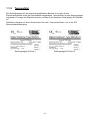
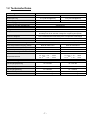
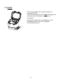
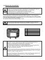
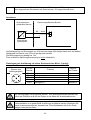
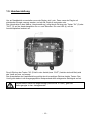
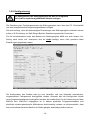
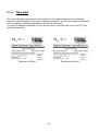
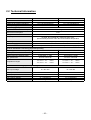
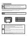
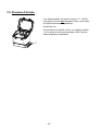
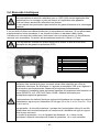
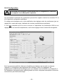
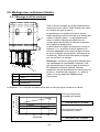
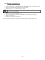
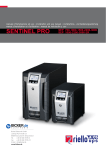
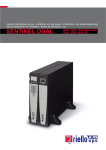
Betriebsanleitung Operating Instructions Manuel d'utilisation 8049-Ex ATEX 8049-Ex, 8049-Ex-0 Version: 09/2011 M8049-Ex-def.doc Art.-Nr: 112 8049 Bunsenstrasse Tel: (0841) 9654-0 www.schubert-salzer.com D-85053 Ingolstadt Fax: (0841) 9654-590 Inhalt/Content/Sommaire Inhalt/Content/Sommaire .............................................................................................................................2 Betriebsanleitung (deutsch).......................................................................................................4 1 1.1 Allgemeines ....................................................................................................................................4 1.1.1 Anbau.............................................................................................................................................4 1.1.2 Bestimmungsgemäßer Gebrauch ....................................................................................................4 1.1.3 Gesetze und Bestimmungen ............................................................................................................5 1.1.4 Allgemeine Sicherheitshinweise ......................................................................................................5 1.1.5 Typenschild ....................................................................................................................................6 1.2 Technische Daten............................................................................................................................7 1.3 Zuluft .............................................................................................................................................8 1.4 Elektrische Anschlüsse ...................................................................................................................9 1.5 Handverstellung ........................................................................................................................... 12 1.6 Einstellungen ................................................................................................................................ 13 1.7 Fehlermeldungen/Betriebszustände .............................................................................................. 15 1.8 Störungsbeseitigung...................................................................................................................... 15 1.9 Montage bei Linearantrieben ....................................................................................................... 16 1.10 Montage bei Schwenkantrieben .................................................................................................... 18 1.11 Wartung und Instandhaltung ....................................................................................................... 20 1.12 Abmessungen und Gewichte ......................................................................................................... 21 Operating Instructions (English) .................................................................................22 2 2.1 General......................................................................................................................................... 22 2.1.1 Installation ................................................................................................................................... 22 2.1.2 Intended use ................................................................................................................................. 22 2.1.3 Laws and regulations.................................................................................................................... 23 2.1.4 General safety instructions ........................................................................................................... 23 2.1.5 Tape plate..................................................................................................................................... 24 2.2 Technical Information .................................................................................................................. 25 2.3 Supply Pressure ............................................................................................................................ 26 2.4 Electrical Connections .................................................................................................................. 27 2.5 Manual Override .......................................................................................................................... 30 2.6 Configuration ............................................................................................................................... 31 2.7 Fault messages/Operating modes .................................................................................................. 33 2.8 Troubleshooting............................................................................................................................ 33 2.9 Mounting On Linear Actuators .................................................................................................... 34 2.10 Mounting instructions for part-turn actuators.............................................................................. 36 2.11 Maintenance and repairs .............................................................................................................. 38 2.12 Dimensions and Weights............................................................................................................... 39 -2– 3 4 Instructions de service (français)...........................................................................................40 3.1.1 Pose .............................................................................................................................................. 40 3.1.2 Utilisation conforme aux prescriptions ......................................................................................... 40 3.1.3 Lois et règlements ......................................................................................................................... 41 3.1.4 Consignes de sécurité générales .................................................................................................... 41 3.1.5 Plaque signalétique ....................................................................................................................... 42 3.2 Caractéristiques Technique .......................................................................................................... 43 3.3 Pression d'arrivée ......................................................................................................................... 44 3.4 Raccords électriques ..................................................................................................................... 45 3.5 Actionnement manuel ................................................................................................................... 48 3.6 Configuration ............................................................................................................................... 49 3.7 Messages d'erreur/États de fonctionnement ................................................................................. 51 3.8 Suppression des perturbations...................................................................................................... 51 3.9 Montage avec actionneur linéaire ................................................................................................. 52 3.10 Montage sur actionneurs rotatifs .................................................................................................. 54 2.11. Maintenance et entretien .............................................................................................................. 56 3.11 Dimensions et poids ...................................................................................................................... 57 Anhang / Annex / Annexe ..................................................................................................................58 -3– 1 Betriebsanleitung (deutsch) 1.1 Allgemeines Neben den Hinweisen in dieser Druckschrift müssen die allgemeingültigen Sicherheits- und Unfallverhütungsvorschriften berücksichtigt werden. Sollten die in dieser Druckschrift enthaltenen Informationen in irgendeinem Fall nicht ausreichen, so steht Ihnen unser Service gerne mit weitergehenden Auskünften zur Verfügung. Vor der Installation und Inbetriebnahme lesen Sie bitte diese Druckschrift sorgfältig durch. 1.1.1 Anbau Der Stellungsregler kann auf jedes pneumatische Stellventil mit Hüben von 3 bis 28 mm aufgebaut werden („Top-Mounted“). Um den Anbau an das Ventil zu vereinfachen, stehen verschiedene Anbausätze zur Verfügung, die die erforderlichen Anbauteile für das Verbinden des Ventilantriebs und des Stellungsreglers, eine Rückführ-Taststange für den Ventilhub und bei Bedarf eine optische Ventilpositionsanzeige umfassen. Da die Adaption des Stellungsreglers an den Ventilhub automatisch erfolgt, wird ein StandardAnbausatz verwendet, der jedoch antriebsseitig den mechanischen Gegebenheiten des Ventils bei Bedarf angepasst werden kann. Alle anderen Betriebsparameter (wie z.B. "Split-Range"Betrieb) können über eine entsprechende Konfigurationssoftware, die bei Bedarf geliefert werden kann, eingestellt werden. 1.1.2 Bestimmungsgemäßer Gebrauch Der Stellungsregler 8049 dient zum Positionieren von pneumatisch gesteuerten Stellgliedern. Er ist vorgesehen zum Anbau an Linear- und Schwenkantriebe gemäß den Anweisungen in dieser Betriebsanleitung. Das Gerät darf nur für die in dieser Betriebsanleitung bzw. in den Datenblättern beschriebenen Anwendungsfälle eingesetzt werden. Jeder andere Gebrauch gilt als bestimmungswidrig. Für Anwendungen im explosionsgefährdetem Bereich sind 2 Varianten unter folgenden Typbezeichnungen erhältlich: 8049-Ex 8049-Ex-0 (für Einsatz in Zone 1) (für Einsatz in Zone 0) -4– Die Zonen sind dabei folgendermaßen definiert: Zone 0: Zone 1: Bereich, in dem gefährliche explosionsfähige Atmosphäre als Gemisch aus Luft und brennbaren Gasen, Dämpfen oder Nebeln ständig, über lange Zeiträume oder häufig Bereich, in dem sich bei Normalbetrieb gelegentlich eine gefährliche explosionsfähige Atmosphäre als Gemisch aus Luft und brennbaren Gasen, Dämpfen oder Nebeln bilden kann. vorhanden ist. Der Typ 8049-Ex-0 kann für beide Zonen verwendet werden. Für den Einsatz in der Zone 0 darf nur der 8049-Ex-0 verwendet werden! 1.1.3 Gesetze und Bestimmungen Bei Anschluss, Montage und Inbetriebnahme, sind die im jeweiligen Land gültigen gesetzlichen Bestimmungen einzuhalten. Dies sind insbesondere für explosionsgefährdete Bereiche zum Beispiel: IEC 60079-14 (international) EN 60079-14 (EU, Deutschland) Die Betriebssicherheitsverordnung (Deutschland) 1.1.4 Allgemeine Sicherheitshinweise Das Gerät darf nur von Fachpersonal, das mit der Montage, der Inbetriebnahme und dem Betrieb dieses Produktes vertraut ist, montiert und in Betrieb genommen werden. Fachpersonal im Sinne dieser Einbau- und Bedienungsanleitung sind Personen, die auf Grund ihrer fachlichen Ausbildung, ihrer Kenntnisse und Erfahrungen sowie ihrer Kenntnisse der einschlägigen Normen die ihnen übertragenen Arbeiten beurteilen und mögliche Gefahren erkennen können. Bei Geräten in explosionsgeschützter Ausführung müssen die Personen eine Ausbildung oder Unterweisung bzw. eine Berechtigung zum Arbeiten an explosionsgeschützten Geräten in explosionsgefährdeten Anlagen haben. Gefährdungen, die am Stellventil vom Durchflussmedium und dem Betriebsdruck sowie dem Stelldruck und von beweglichen Teilen ausgehen können, sind durch geeignete Maßnahmen zu verhindern. Falls sich durch die Höhe des Zuluftdrucks im pneumatischen Antrieb unzulässige Bewegungen oder Kräfte ergeben, muss der Zuluftdruck durch eine geeignete Reduzierstation begrenzt werden. Die Abluftöffnung darf bauseits nicht verschlossen werden. Sachgemäßer Transport und fachgerechte Lagerung des Gerätes werden vorausgesetzt. -5– 1.1.5 Typenschild Bei Stellungsreglern für den explosionsgefährdeten Bereich ist je nach Art des Explosionsschutzes eines der nachstehend dargestellten Typenschilder an dem Stellungsregler angebracht. Es zeigt den Explosionsschutz und das für Ihr jeweiliges Gerät gültige Ex-Zertifikat an. Detaillierte Angaben zu Ihrem Gerät finden Sie unter „Technische Daten“ und in der EGBaumusterbescheinigung. Stellungsregler für Zone 1 Stellungsregler für Zone 0 -6– 1.2 Technische Daten Ausführung Nennhub Bürdenspannung Hilfsenergie, pneumatisch 8049-Ex 8049-Ex-0 3 - 28 mm 3 - 28 mm 14 V (700 Ohm@20mA) 14 V (700 Ohm@20mA) 4,5 - 6 bar 4,5 - 6 bar 30 Nl/min. Luftleistung (@5bar) selbstlernend Anpassung von Hub und Nullpunkt keiner Eigenluftverbrauch Über PC-Software Konfiguration Luftqualität Nicht geölte, trockene Industrieluft, Feststoffgehalt < 30µ, Drucktaupunkt 20 K unter der niedrigsten Umgebungstemperatur Anbau an Stellgerät Über standardisierte Anbausätze (auch mit optischer Hubanzeige) G 1/8" Druckanschluss Schutzart nach DIN 40050 IP 65 (zusätzlich Überdruck im Gehäuse durch Spülluft) Allgemeine Ex-relevante Angaben Baumusterprüfbescheinigung (ATEX) ATEX-Kennzeichnung BVS 08 ATEX E154 BVS 08 ATEX E154 II 2G Ex ia T3/T4 II 1G Ex ia T3/T4 IECEx BVS 11.0060 IECEx BVS 11.0060 IEC-Kennzeichnung Ex ia IIC T3/T4 Gb Ex ia IIC T3/T4 Ga Temperaturbereiche T4: Tamb = -10 … +40°C T3: Tamb = -10 … +75°C T4: T amb = -10 … +40°C T3: T amb = -10 … +75°C Ui = DC 30V Ui = DC 30V Ii = 100mA Ii = 100mA max. Eingangsleistung Pi = 633mW Pi = 633mW max. innere Kapazität Ci = vernachlässigbar Ci = vernachlässigbar max. innere Induktivität Li = vernachlässigbar Li = vernachlässigbar Baumusterprüfbescheinigung (IEC) Ex-relevante Angaben max. Eingangsspannung max. Eingangsstrom -7– 1.3 Zuluft Die Versorgungsluft wird mit dem Eingang "P" verbunden (G1/8"). Sie darf einen Druck von 6 bar nicht übersteigen, da sonst mit einer Fehlfunktion zu rechnen ist. Luftqualität: Nicht geölte Industrieluft, Feststoffgehalt < 30µ, Drucktaupunkt 20 K unter der niedrigsten Umgebungstemperatur. P -8– 1.4 Elektrische Anschlüsse Der elektrische Anschluss darf nur durch qualifiziertes Personal erfolgen. Beachten Sie unbedingt bei Montage, Inbetriebnahme und Betrieb der Geräte die entsprechenden nationalen Sicherheitsvorschriften (z. B. VDE 0100). Alle Arbeiten dürfen nur im spannungslosen Zustand erfolgen. Bei Nichtbeachten der entsprechenden Vorschriften können schwere Körperverletzungen und/oder Sachschäden auftreten. Für den elektrischen Anschluss werden geschirmte Kabel empfohlen. Ist eine zusätzliche Spannungsversorgung erforderlich, so sollte diese über ein getrenntes zweites Kabel erfolgen. Nach dem Öffnen des Deckels des Stellungsreglers sind die Schraubklemmen der Klemmleiste (1) für die einzelnen Anschlüsse zugänglich. Der maximale Anschlussquerschnitt beträgt 1,5 mm² Nicht verwendete Kabelverschraubungen sind unbedingt mit einem geeigneten Verschlussstopfen abzudichten um die Schutzart (IP65) zu erhalten. 1 2 3 4 5 6 7 8 Klemmleiste Taste "IN" Taste "OUT" LED rot LED grün Funktionserde/Schirm Anschluss für Interface Steckplätze für Zusatzmodule Bei der elektrischen Installation sind die einschlägigen elektrotechnischen Vorschriften und die Unfallverhütungsvorschriften des Bestimmungslandes zu beachten. In Deutschland sind dies die VDE-Vorschriften und die Unfallverhütungsvorschriften der Berufsgenossenschaften. Für die Montage und Installation in explosionsgefährdeten Bereichen gilt die EN 60079-14:3; VDE 0165 Teil 1/8.98 „Elektrische Betriebsmittel für gasexplosionsgefährdete Bereiche Für die Zusammenschaltung der eigensicheren elektrischen Betriebsmittel gelten die zulässigen Höchstwerte der EG-Baumusterprüfbescheinigung (Ui bzw. Uo, li bzw. Io, Pi bzw. Po: Ci bzw. Co und Li bzw. Lo). Geräte der Zündschutzart "Eigensicherheit" verlieren ihre Zulassung, sobald sie an Stromkreisen betrieben wurden, die nicht der in Ihrem Land gültigen Prüfbescheinigung entsprechen. -9– Das Schutzniveau "ia" des Geräts wird auf Schutzniveau "ib" herabgesetzt, wenn eigensichere Stromkreise mit Schutzniveau "ib" angeschlossen sind. Anschluss: Nicht explosionsgefährdeter Bereich + EEx I Explosionsgefährdeter Bereich 0/4 ... 20mA 1 2 - Eigensichere Speisequelle Als Stellsignal ist ein Stromsignal von 4-20 mA anzulegen (Der Regler kann auch auf andere Stellsignale im Bereich von 4-20 mA konfiguriert werden). Die Bürdenspannung beträgt ca. 14V. Eine zusätzliche Spannungsversorgung ist nicht erforderlich. Pinbelegung bei Ausführung mit einem Steckanschluss M12x1 (5-polig): Draufsicht auf Stecker des Stellungsreglers 4 3 5 1 2 Pin am Stecker Pin Pin Pin Pin 1 2 3 4 Pin 5 Funktion Klemme auf Platine Stellsignal (+) Klemme 1 Stellsignal (-) Klemme 2 Der Stellungsregler muss geerdet werden. Eine Erdungsschraube befindet sich außen am Gehäuse und auf der Platine in der Nähe der Anschlussklemmen.. Für den Einsatz des Stellungsreglers im explosionsgefährdeten Bereich muss ein Trennverstärker in ex-geschützter Ausführung eingesetzt werden. Beachten Sie immer (insbesondere bei der Auswahl des Trennverstärkers) die für Ihr Gerät gültigen technischen Daten. - 10 – Beispiele für zulässigeTrennverstärker Firma Artikel-Nummer Versorgungsspannung Stahl 9165/16-11-11 24V DC Stahl 9165/26-11-11 24V DC Siemens 7NG4130-AA11 24V DC Siemens 7NG4130-BA11 95-253V AC Bemerkung 2 Kanäle Störmeldeausgang Bei den Reglern in Ex-Ausführung ist kein Störmeldeausgang verfügbar. Geräte, die für den Einsatz in Zone 0 vorgesehen sind, müssen mit metallischen Kabeleinführungen versehen sein. - 11 – 1.5 Handverstellung Um auf Handbetrieb umzustellen muss der Regler „aktiv“ sein. Dazu muss der Regler mit elektrischer Energie versorgt werden und mit der Druckluft verbunden sein. Das Umschalten in den Modus „Handverstellung“ erfolgt durch Drücken der Tasten "IN" (2) oder "OUT" (3) auf der Anschlussplatine für ca. zwei Sekunden. Die rote LED (4) auf der Anschlussplatine leuchtet auf. Durch Drücken der Tasten "IN" (Zuluft in den Antrieb) bzw. "OUT" (Antrieb wird entlüftet) wird das Ventil auf bzw. zu bewegt. Das Ausschalten der Handverstellung erfolgt durch kurzzeitiges Drücken beider Tasten. Das Ventil geht wieder in die Ausgangsposition entsprechend dem anliegenden Stellsignal zurück. Werden beide Tasten zu lange betätigt (mehr als ca. 2-3 sec.), geht der Stellungsregler in den Justagebetrieb. - 12 – 1.6 Einstellungen 1.6.1 Selbstabgleich Die Justierung (Selbstabgleich) des montierten Stellungsreglers wurde im Werk vorgenommen. Sie ist normalerweise nur nach einem Austausch oder evtl. nach einer Reparatur des Ventils erforderlich. Nachdem ein neuer oder getauschter Stellungsregler auf das Ventil montiert wurde, muss er wie folgt justiert werden. Dazu muss der Regler mit elektrischer Energie versorgt werden und mit der Druckluft verbunden sein. 1. Beide Tasten "IN" und "OUT" drücken bis die grüne LED leuchtet (nach 2-3 Sekunden) 2. Das Ventil öffnet und schließt mehrmals, nach Beendigung erlischt die LED. Eine leuchtende rote LED weist auf einen Fehler hin (z.B. zu geringer Zuluftdruck!). 3. Nach Beenden der Justierung wechselt der Regler bei fehlerfreiem Abgleich selbstständig wieder in den Regelbetrieb. - 13 – 1.6.2 Konfigurierung Die Konfiguration des Stellungsreglers mit dem PC-Programm darf nicht im explosionsgefährdeten Bereich erfolgen. Die Einstellung der Funktionsparameter des Stellungsreglers kann über eine PC -Schnittstelle und eine entsprechende Konfigurierungssoftware erfolgen. Sie wird benötigt, wenn die werksseitigen Einstellungen des Stellungsreglers verändert werden sollen (z.B. Einrichtung von Split-Range-Betrieb, Realisierung spezieller Kennlinien). Für die Inbetriebnahme sowie den Betrieb des Stellungsreglers 8049 und auch dessen Justierung nach einem evtl. Austausch wird sie nicht benötigt, wenn nicht spezielle lokale Einstellungen gespeichert waren. Die Konfiguration des Gerätes darf nur vom Hersteller und vom Hersteller autorisiertem, eingewiesenem Fachpersonal durchgeführt werden. Alternativ darf die Konfiguration mittels eines Programmieradapters durchgeführt werden, der ausdrücklich für die Verwendung mit dem 8049-Ex bzw. 8049-Ex-0 freigegeben ist. In diesem speziellen Programmieradapter sind sämtliche schaltungstechnische Maßnahmen berücksichtigt worden um sicherzustellen, dass keine sicherheitsrelevanten Bauteile im Stellungsregler beschädigt werden können. - 14 – 1.7 Fehlermeldungen/Betriebszustände Der Stellungsregler zeigt seine Betriebszustände durch zwei LEDs an. Die Bedeutung der Signale kann den nachfolgenden Tabelle entnommen werden. LED-Rot • LED-Grün Fehler Bedeutung Regelfehler (Wenn nicht im Handbetrieb) OFF Das Ventil erreicht nich seine Sollposition Betriebszustand • OFF 1.8 OFF Handbetrieb • Regler befindet sich im Selbstabgleich Störungsbeseitigung Fehler / Symptom Antrieb bewegt sich nicht Mögliche Ursache(n) • Steuerdruck ist zu gering Antrieb fährt nicht bis zum Anschlag (bei 20mA) • Steuerdruck ist zu gering • Regler ist nicht richtig abgeglichen • Leckage in Verbindung vom Stellungsregler zum Antrieb. • Leckage im Antrieb Im stationären Automatikbetrieb (konstanter Sollwert) schalten die Magnetventile ständig. Magnetventile schalten nicht. Ventil öffnet nicht. • Magnetventile nicht richtig kontaktiert • Schmutz (Späne, Partikel) in den Magnetventilen • Taststange ist lose. Vorgehensweise • Steuerdruck auf 4-6 bar erhöhen. • Steuerdruck erhöhen. • Abgleich durchführen • Leckage suchen und beseitigen. • Dichtungen des Antriebs wechseln. • Steckverbindung der Magnetventile überprüfen. • Magnetventile tauschen. • Sitz der Taststange überprüfen Regler funktioniert nicht. • Polarität des Stellsignals ist vertauscht. • Polarität des Stellsignals überprüfen Positionen des Ventils werden nicht richtig angefahren. Regler reagiert nicht auf Stellsignal. • Regler ist nicht richtig abgeglichen. • Selbstabgleich durchführen. • Regler befindet sich im Handbetrieb. Rote LED leuchtet. • Durch drücken der beiden Tasten (IN und OUT) in den Automatikmodus wechseln.. - 15 – 1.9 Montage bei Linearantrieben 1.9.1 Montage des Anbausatzes Der Anbausatz wird an der Oberseite des Ventilantriebs befestigt. Je dach Ventilbauart kann diese Befestigung unterschiedlich sein. 4 Der Anschlag muss so eingestellt sein, dass das Maß „X“, gemessen von der Oberkante des Adapterrings bis zur Auflagefläche bei nicht druckbetätigtem Ventil, erreicht wird (siehe unten). Er muss nach der Einstellung durch Kontern oder Verklebung gesichert werden. X 3 2 Anmerkung: je nach Antriebskonstruktion wird möglicherweise keine optische Sichtanzeige benötigt (z.B. bei Membranantrieben mit Säulenaufbau). In diesem Fall wird lediglich der Adapterring direkt auf dem Ventilantrieb befestigt; das Einstellmaß „X“ bleibt jedoch gleich, d.h. die Taststange reicht in den Antrieb hinein. 1 1 Ventilantrieb 2 Anschlag 3 Anbausatz 4 Stellungsregler Die Ankoppelung des Stellungsreglers an das Ventil erfolgt über einen mechanischen Anschlag der ventilseitig vorzusehen ist und mit der Ventilspindel verbunden sein muss. Auf der planen Oberfläche des Anschlags liegt die Rückführ-Taststange mit Rückstellfeder auf, die die Ventilstellung an den Regler weitermeldet. Das Maß „X“ ist nicht konstant, sondern hängt vom Ventilhub ab: Bei federschließenden Antrieben gilt: 65 "X" mm 60 Feder schließt 55 X in mm = 50,8 + Hub/2 50 45 40 35 Feder öffnet und bei federöffnenden Antrieben: 30 0 5 10 15 20 25 X in mm = 50,8 - Hub/2 Hub mm - 16 – 1.9.2 Montage des Stellungsreglers Stellungsregler inkl. Taststange und Rückstellfeder auf den Anbausatz aufsetzen. Am Befestigungsring seitlich die 3 Gewindestifte festziehen. Ausgang "Y1" mit dem Ventilantrieb verbinden. Achten Sie darauf, dass diese Verbindung dicht ist, weil dies sonst dazu führt, dass die Magnetventile im Stellungsregler permanent arbeiten. Zuluft (Anschluss „P“) anschließen. Deckel des Stellungsreglers öffnen und elektrische Verbindungen herstellen. Justierung des Stellungsreglers durchführen. Deckel des Stellungsreglers schließen. Demontage des Stellungsreglers sinngemäß in umgekehrter Reihenfolge durchführen. - 17 – 1.10 Montage bei Schwenkantrieben Der digitale Stellungsregler für Schwenkantriebe ist für den Anbau auf Schwenkantriebe mit Anbausatz nach VDI/VDE 3835 konzipiert. Bei Doppelwirkenden Antrieben: 1. Ventil in die „geschlossen“ Stellung fahren. 2. Kupplung(1) drehen, bis der Drehwinkelanzeiger(2) auf 0° steht. Bei Einfachwirkenden Antrieben „Feder schließt“: 1. Antrieb nicht mit Druckluft beaufschlagen. 2 1 2. Kupplung(1) drehen, bis der Drehwinkelanzeiger(2) auf 0° steht. Bei Einfachwirkenden Antrieben „Feder öffnet“: 1. Antrieb nicht mit Druckluft beaufschlagen. 2. Kupplung(1) drehen, bis der Drehwinkelanzeiger(2) auf 90° steht. - 18 – 3 5 4 2 25 6 1 A 3. Stellungsregler auf die Konsole des Anbausatzes aufsetzen. Die Kupplung muss dabei in die Nut des Antriebs (A) einrasten. 4. Stellungsregler mit Schrauben(4) und Scheiben(5) an der Konsole befestigen. 5. Gewindestifte der Kupplung (1) und des Ringes (2) niemals lösen! 6. Pneumatische Verbindungen zwischen Stellungsregler und Antrieb herstellen. o Bei einfachwirkenden Antrieben: Ausgang Y1 o Bei doppelwirkenden Antrieben: Ausgang Y1 und Y2 Achten Sie darauf, dass diese Verbindung dicht ist, weil dies sonst dazu führt, dass die Magnetventile im Stellungsregler permanent arbeiten. 7. Deckel des Stellungsreglers öffnen und elektrische Verbindungen herstellen. 8. Zuluft (Anschluss „P“) anschließen. 9. Justierung des Stellungsreglers durchführen. 10. Deckel des Stellungsreglers schließen. Demontage des Stellungsreglers sinngemäß in umgekehrter Reihenfolge durchführen. - 19 – 1.11 Wartung und Instandhaltung Das Gerät ist wartungsfrei. An der Rückseite des metallischen Gehäuseunterteils befindet sich ein Filtereinsatz, der bei Bedarf herausgeschraubt und gereinigt bzw. ersetzt werden kann. Die Wartungsvorschriften von eventuell vorgeschalteten Zuluft-Reduzierstationen sind zu beachten. 1.11.1 Instandsetzung Ex-Geräte Wird der Stellungsregler mit einem Teil von dem der Explosionsschutz abhängt instand gesetzt, so darf er erst dann wieder in Betrieb genommen werden, wenn ein Sachverständiger das Betriebsmittel gemäß den Anforderungen des Explosionsschutzes überprüft hat, darüber eine Bescheinigung ausgestellt oder das Betriebsmittel mit seinem Prüfzeichen versehen hat. Die Prüfung durch den Sachverständigen kann entfallen, wenn das Betriebsmittel vor der erneuten Inbetriebnahme vom Hersteller einer Stückprüfung unterzogen wird und die erfolgreiche Stückprüfung durch das Anbringen eines Prüfzeichens auf dem Betriebsmittel bestätigt wurde. Der Austausch von Ex-Komponenten darf nur mit original stückgeprüften Komponenten des Herstellers erfolgen. Geräte, die bereits außerhalb explosionsgefährdeter Bereiche verwendet wurden und künftig innerhalb explosionsgefährdeter Bereiche eingesetzt werden sollen, unterliegen den Bestimmungen für instand gesetzte Geräte. Sie sind vor dem Einsatz innerhalb explosionsgefährdeter Bereiche entsprechend den Bedingungen die für die „Instandsetzung von Ex-Geräten“ gelten einer Prüfung zu unterziehen. - 20 – 1.12 Abmessungen und Gewichte 115 121 M16x1,5 24 P 49 8,5 A G1/8" 2 56 65 66 Gewicht ca. 1 kg - 21 – 2 Operating Instructions (English) 2.1 General In addition to the instructions in this publication, the generally applicable safety and accident prevention regulations must be observed. If the information in this publication is insufficient in any way, our service organisation will be happy to provide you with further information. Before installation and start-up, please read through this publication carefully. 2.1.1 Installation The positioner can be mounted to any pneumatic control valve with a stroke of 3 to 28 mm (“top-mounted” design). To ease mounting the valve various mounting kits are available which contain the required parts to connect valve actuator and positioner, a feedback pin for sensing the valve stroke and an optical valve position indicator if required. As the adaptation of positioner to valve stroke is carried out automatically a standard mounting kit is used, which can be adapted to the mechanical actuator requirements in case. All other operation parameters (e.g. “split-range” operation) can be set through configuration software which is supplied on request. . 2.1.2 Intended use The 8049 positioner is a control device to position pneumatically-controlled actuators. It is supplied for installation on linear and swivel actuators in accordance with the instructions in this operating manual. The device must be used solely for the applications described in this operating manual and in the data sheets. Any other application will be in breach of its intended use. For applications in a potentially explosive area, 2 versions are available with the following type designations: 8049-Ex 8049-Ex-0 (for use in zone 1) (for use in zone 0) - 22 – The zones concerned are defined as follows: Zone 0: Zone 1: An area in which a dangerous, potentially explosive atmosphere of air and combustible gases, vapours or mists is present continuously, over long periods or frequently. An area in which a dangerous, potentially explosive atmosphere of air and combustible gases, vapours or mists is likely to occur in normal operation occasionally. The 8049-Ex-0 can be used for both zones. Only the 8049-Ex-0 may be used in zone 0! 2.1.3 Laws and regulations Legal regulations in force in the country concerned must be observed in connecting, fitting and starting operation. In particular, the following examples apply to potentially explosive areas: IEC 60079-14 (international) EN 60079-14 (EU, Germany) The Ordinance on Industrial Safety and Health (Germany) 2.1.4 General safety instructions The device may be fitted and started in operation only by qualified personnel who are familiar with the fitting, start up and operation of this product. Qualified personnel within the meaning of these installation and operating instructions are those persons who, due to their professional training, knowledge and experience as well as their knowledge of applicable standards can assess the work assigned to them and recognise potential dangers. With regard to devices designed to be explosion-proof, the personnel must be trained or instructed, or have permission, to work on explosion-proof devices in potentially explosive plants. Hazards that may arise at the control valve from the flowing medium and the operating pressure, as well as the actuating force and from moving parts must be prevented by adopting suitable measures. If there is a possibility of excessive movements or forces due to the magnitude of the supply air pressure in pneumatic actuation, the supply air pressure must be limited by a suitable reducing station. The exhaust air opening must not be closed by the customer. Appropriate transportation and proper storage of the device are taken as given. - 23 – 2.1.5 Tape plate One of the following type plates is to be attached in the case of positioners for potentially explosive areas according to the type of explosion protection. It shows the explosion protection and the explosion certificate applicable to the device concerned. You can find detailed information on your device under “Technical data” and in the EC Type Approval Certificate. Positioner for Zone 1 Positioner for Zone 0 - 24 – 2.2 Technical Information Version 8049-Ex 8049-Ex-0 3 - 28 mm 3 - 28 mm 14 V (700 Ohm@20mA) 14 V (700 Ohm@20mA) 4,5 - 6 bar 4,5 - 6 bar nominal stroke voltage of the working resistance auxiliary energy, pneumatic 30 Nl/min. air delivery (@5bar) self-learning adjustment of stroke and zero point none internal air consumption with PC-Software configuration air quality not oiled, dry industrial air, content of solid < 30 µ, pressure dew point 20 K under the lowest ambient temperature mounting to control valve standardized mounting kits (also with optical position indicator) G 1/8" pressure supply port protection class acc. DIN 40050 IP 65 (additional over pressure in the body with scavenging air) general information concerning explosion-proofing product type test certificate (ATEX) BVS 08 ATEX E154 BVS 08 ATEX E154 II 2G Ex ia T3/T4 II 1G Ex ia T3/T4 IECEx BVS 11.0060 IECEx BVS 11.0060 Ex ia IIC T3/T4 Gb Ex ia IIC T3/T4 Ga T4: Tamb = -10 … +40°C T3: Tamb = -10 … +75°C T4: T amb = -10 … +40°C T3: T amb = -10 … +75°C ATEX specification product type test certificate (IEC) IEC specification temperature ranges information concerning explosion-proofing max. input voltage Ui = DC 30V Ui = DC 30V max. input current Ii = 100mA Ii = 100mA max. input power Pi = 633mW Pi = 633mW max. interior capacity Ci = insignificant Ci = insignificant max. interior inductance Li = insignificant Li = insignificant - 25 – 2.3 Supply Pressure The supply pressure is connected to port "P" (G1/8"). It must not exceed 6 bars, malfunctions might occur then. Air quality: Non-oiled industrial air, solid content < 30 µm (1200 µinch), pressure dew point 20 K below lowest ambient temperature. P - 26 – 2.4 Electrical Connections The electrical connection must only be carried through by qualified personnel. Follow the respective national safety standards (e. g. VDE 0100) for mounting, start-up and operation. All actions must only be carried through without voltage connected. Disregarding the corresponding standard may cause heavy injuries and/or property damage. Shielded cables are recommended for the electrical connection. An additionally required voltage supply should be connected through a separate second cable. After opening the positioner cover the screw terminals of the connecting block (1) can be accessed. The maximum connector size is 1.5 mm² Cable bushings which are not used should be sealed in any case using a suitable sealing cap to preserve the protection class (IP65). 1 2 3 4 5 6 7 8 screw terminals key "IN" key "OUT" LED red LED green Function end / shield interface connection plug terminal for additional modules The electrical regulations and accident prevention regulations applicable in the country concerned must be observed. In Germany, these are the VDE (Association of Electrical Engineers) regulations and the accident prevention regulations of the professional associations. EN 60079-14:3; VDE 0165 Part 1/8.98 “Electrical apparatus for potentially explosive gas atmospheres” apply for the fitting and installation in potentially explosive atmospheres. The highest permissible values for the EC Type Approval Certificate (Ui or Uo, li or Io, Pi or Po: Ci or Co and Li or Lo) apply for the interconnection of intrinsically safe operating equipment. Devices of the “intrinsically safe” ignition type of protection lose their approval as soon as they are operated in electrical circuits that do not conform to the test certificate in force in their country. - 27 – The “ia” protection level of the device is downgraded to “ib” when intrinsically safe electrical circuits with an “ib” protection level are connected. Connection: Potentially explosive area Non-potentially explosive area + EEx I 0/4 ... 20mA 1 2 Positioner 8049-Ex 8049-Ex-0 - Intrinsically safe power source A current signal of 4-20 mA is applied as a set point signal (the controller can also be configured to other set point signals in the range of 4-20 mA). The voltage rating is approximately 14V. An additional power supply is not required. Pin assignment for version with a plug and socket connection M12x1 (5-pin): Top view of positioner plug 4 3 5 1 2 Pin on plug Pin 1 Pin 2 Pin 3 Pin 4 Pin 5 Function Terminal on PCB Set point signal (+) Terminal 1 Set point signal (-) Terminal 2 The positioner has to be earthed. An earthing screw is located on the outside of the casing and on the PCB near the connection terminals. Also, shielded cables must be used. An explosion-proof isolation amplifier must be used if the positioner is to be used in an explosive environment. Ensure that (especially when selecting an isolation amplifier) the specifications and specific requirements of your device in accordance with the applicable certificate are observed. - 28 – Examples of permissible isolation amplifiers Manufacturer Item number Supply voltage Stahl 9165/16-11-11 24V DC Stahl 9165/26-11-11 24V DC Siemens 7NG4130-AA11 24V DC Siemens 7NG4130-BA11 95-253V AC Notes 2 channels Alarm output An alarm output is not provided for explosion-proof controllers. Devices designed for use in zone 0 must be provided with metallic cable glands. - 29 – 2.5 Manual Override Switching over to manual operation requires an “active” positioner, i.e. the positioner has to be powered electrically and connected to the supply air. Switching over to manual operation mode is carried through by pushing button "IN" (2) or "OUT" (3) on the connecting plate for two seconds approximately. The red LED (4) on the connecting plate lights up. Pushing button "IN" (supply air to actuator) or "OUT" (actuator is vented) opens or closes the valve. Switching off the manual operation mode is carried through by pushing both buttons for a short moment. The valve moves back to its initial position corresponding to the valid set-point signal. If both buttons are actuated more than 2-3 seconds, the positioner switches to selfadjusting mode. - 30 – 2.6 Configuration 2.6.1 Self Adjusting Mode The adjustment (self adjusting) of mounted positioners has been carried through in the factory. Normally it is only required after replacing a positioner or repairing the valve. After a new or replaced positioner has been mounted to the valve it has to be adjusted as follows. The positioner has to be powered electrically and connected to the supply air. 1. Press both buttons "IN" and "OUT" until the green LED lights up (after 2-3 seconds). 2. The valve opens and closes several times, after completion the LED turns off. A lit red LED indicates an error (e.g. supply air pressure too low!). 3. After completing the adjustment free from errors the positioner return to control mode automatically. - 31 – 2.6.2 Configuration Configuring the positioner using the PC program must not be carried out in the potentially explosive area. Setting the positioner function parameters can be carried out using a PC interface and the corresponding configuration software. This software is required if the factory settings of the positioner have to be modified (e.g. setting up split-range operation, implementation of special flow characteristics). It is not required for start-up and operation of the 8049 positioner nor adjustment after a potential replacement if no special local settings were stored. Configuration of the device must be carried out only by the manufacturer or qualified personnel authorised and trained by the manufacturer. Alternatively, the configuration may be performed using a programming adapter which is approved expressly for use with the 8049-Ex or 8049-Ex0. All connection means have been provided for in this special programming adapter to ensure that no safety-related components in the positioner may be damaged. - 32 – 2.7 Fault messages/Operating modes The operating mode of the positioner is indicated by two LEDs. The signals are explained in the following table. LED red • LED green Fault Control fault (unless in manual mode) OFF Description Valve does not reach target position Operating mode • OFF 2.8 OFF Manual mode • Positioner is performing self-calibration Troubleshooting Fault / Symptom Actuator does not move Possible cause(s) • Pilot pressure is too low. Actuator does not move right up to stop (at 20mA). • Pilot pressure is too low Positioner is not adjusted correctly. • Leak in connection from positioner to actuator. • Leak in actuator. In stationary automatic operation (constant set point signal) the solenoid valves continue to operate. Solenoid valves are not operating. Valve fails to open. • Faulty solenoid valve connections. • Contamination (swarf, particles) in the solenoid valves. • Feedback pin is loose. Action • Increase pilot pressure to 4-6 bar. • Increase pilot pressure. • Make adjustments. • Find leak and correct. • Change seals in actuator. • Check solenoid valve plug connections. • Exchange solenoid valves. • Check feedback pin seat. Positioner not working. • Polarity of set point signal • Check polarity of set point has reversed. signal. Valve positions not reached correctly. Positioner does not respond to set point signal. • Positioner is not adjusted correctly. • Positioner is in manual mode. Red LED is on. - 33 – • Run self-adjustment. • Change to automatic mode by pressing both buttons (IN and OUT). 2.9 Mounting On Linear Actuators 2.9.1 Fixing the Mounting Kit The mounting kit is attached to the upper end of the valve actuator. This attachment might vary due to the different actuator designs. 4 X 3 2 1 1 valve actuator 2 stopper 3 mounting kit 4 positioner Coupling the positioner to the valve is carried through using a mechanical stopper which is connected to the valve stem. Feedback pin and spring are positioned on its flat surface and feed back the valve position to the positioner. The stopper has to be adjusted in such a way that dimension “X“ (measured from the upper edge of the adapting ring to the flat surface of the not actuated valve) is achieved (see below). The stopper has to be fixed by locking or some adhesive. Remark: Depending on the actuator design possibly no position (e.g. diaphragm actuators with columns). In this case the adaptor ring is fixed directly to the valve actuator. However the adjustment dimension “X“ remains the same, i.e. the feedback pin extends into the actuator. - 34 – Dimension “X“ is not constant but depends on the valve stroke: Valid for actuators with springs to close: 65 60 spring closes "X" mm 55 X in mm = 50.8 + stroke/2 50 45 Valid for actuators with springs to open: 40 35 spring opens 30 0 5 10 15 20 25 X in mm = 50.8 - stroke/2 stroke mm 2.9.2 Mounting the Positioner Put positioner with feedback pin and spring on mounting kit. Tighten the three threaded pins in the fastening ring. Connect output "Y1" with valve actuator. Take care that this connection is sealed properly, as otherwise the solenoid valves in the positioner will operate permanently. Connect supply air (port „P“). Open positioner cover and provide the electrical connections. Carry through positioner adjustment. Close positioner cover. Dismount the positioner correspondingly in reverse order. - 35 – 2.10 Mounting instructions for part-turn actuators The digital positioner used for part-turn actuators has been designed so that it can be installed on part-turn actuators using a mounting kit meeting VDI/VDE 3835. For double-acting actuators: 1. Move valve into the “closed” position. 2. Turn coupling (1) until the angle indicator (2) points to 0°. For single-acting actuators with “spring closing”: 1. Actuator must not be under pressure from compressed air. 2 1 2. Turn coupling (1) until the angle indicator (2) points to 0°. For single-acting actuators with “spring opening”: 1. Actuator must not be under pressure from compressed air. 2. Turn coupling (1) until the angle indicator (2) points to 90°. - 36 – 3 5 4 2 25 6 1 A 1. Place the positioner on the mounting kit bracket. In doing so, the coupling must engage in the slot in the actuator (A). 2. Fasten the positioner to the bracket using screws (4) and washers (5). 3. Never loosen the screw pins of the coupling (1) and the ring (2)! 4. Connect the pneumatic supply between the positioner and the actuator. o For single-acting actuators: output Y1 o For double-acting actuators: outputs Y1 and Y2 Ensure that this connection is leak-tight, because otherwise the solenoid valves in the positioner will operate constantly. 5. 6. 7. 8. Open the cover on the positioner and provide the electrical connections. Connect supply air (connection “P”). Adjust the positioner. Close the cover on the positioner. To remove the positioner, follow the same sequence in the reverse order. - 37 – 2.11 Maintenance and repairs The device is maintenance-free. A filter element, located at the rear of the underside of the metal body, can be unscrewed and cleaned or exchanged when necessary. The maintenance instructions for any in-line connected supply air reducing station must be observed. 2.10.1. Repairs to explosion-proof devices If the positioner with a part on which the explosion proofing depends is repaired, it must not be put into operation again until a supervisor has checked the equipment in accordance with the explosion proofing requirements, and has issued a relevant certification or has applied his conformity mark to the equipment. The check by the supervisor can be dispensed with if, before being started up again, the manufacturer has conducted a check test and has confirmed that the check test has been passed by applying a conformity mark to the equipment. Explosion-proof components are to be replaced only by the manufacturer’s original tested components. Devices which have already been used outside potentially explosive atmospheres and are to be used in future in potentially explosive atmospheres are subject to the stipulations for repaired devices. Before they are used in potentially explosive atmospheres they must be checked in accordance with the conditions that apply under “Repairs to explosion-proof devices”. - 38 – 2.12 Dimensions and Weights 115 121 M16x1,5 24 P 49 8,5 A G1/8" 2 56 65 66 Weight 1 kg approx. - 39 – 3 Instructions de service (français) Le règlement de sécurité et de prévention des accidents doit être respecté en plus des consignes données dans ce document. Si les informations contenues dans ce document s’avéraient insuffisantes, notre service après-vente se tient à votre disposition pour tout renseignement supplémentaire. Veuillez lire attentivement ce document avant l’installation et la mise en service. 3.1.1 Pose Le positionneur peut être monté sur n’importe quelle vanne de régulation possédant une course comprise entre 3 et 28 mm (« top-mounted »). Le montage peut être facilité par différents kits de montage comprenant les pièces nécessaires au raccordement de l’actionneur et du positionneur, une tige palpeuse de retour pour la course de la vanne et, au besoin, un affichage optique de la position de la vanne. Etant donné que le positionneur s’adapte automatiquement à la course de la vanne, on utilise un kit de montage standard qui peut être adapté côté actionneur aux propriétés mécaniques de la vanne. Tous les autres paramètres (comme par ex. « split-range ») peuvent être réglés à l’aide d’un logiciel de configuration qui peut être commandé séparément. 3.1.2 Utilisation conforme aux prescriptions Le positionneur 8049 est un régulateur permettant de positionner les actionneurs à commande pneumatique. Il est conçu pour être posé sur des actionneurs linéaires et rotatifs conformément aux instructions de cette notice d’utilisation.. L’appareil doit uniquement être utilisé pour les applications décrites dans cette notice d’utilisation et les fiches signalétiques. Toute autre utilisation est considérée comme non conforme aux prescriptions. Deux versions antidéflagrantes sont disponibles avec les désignations de type suivantes pour les applications dans une atmosphère explosive : 8049-Ex 8049-Ex-0 (pour utilisation en zone 1) (pour utilisation en zone 0) - 40 – Les zones sont définies comme suit : Zone 0 : Zone 1 : Emplacement où une atmosphère explosive consistant en un mélange avec l’air de substances inflammables sous forme de gaz, de vapeur ou de brouillard est présente en permanence, pendant de longues périodes ou fréquemment. Emplacement où une atmosphère explosive consistant en un mélange avec l’air de substances inflammables sous forme de gaz, de vapeur ou de brouillard est susceptible de se présenter occasionnellement en fonctionnement normal. Le type 8049-Ex-0 peut être utilisé pour les deux zones. Seul le type 8049-Ex-0 peut être utilisé dans la zone 0 ! 3.1.3 Lois et règlements Les dispositions légales en vigueur dans le pays d’utilisation doivent être respectées au cours du raccordement, du montage et de la mise en service. Il s’agit notamment des règlements suivants pour les zones exposées aux explosions : IEC 60079-14 (international) EN 60079-14 (EU, Allemagne) La réglementation allemande sur la sécurité dans les entreprises (« Betriebssicherheitsverordnung ») 3.1.4 Consignes de sécurité générales Seul le personnel qualifié et expérimenté pour le montage, la mise en service et l’exploitation de ce produit est autorisé à monter et à mettre cet appareil en service. Dans l’esprit de cette notice de montage et d’utilisation, le personnel qualifié désigne les personnes capables de juger les travaux qui leur sont confiés et de reconnaître les risques éventuels sur la base de leur formation professionnelle, de leur expérience et de leur connaissance des normes correspondantes. Pour les versions antidéflagrantes, ces personnes doivent avoir suivi une formation ou une instruction correspondante ou avoir été habilitées à travailler sur des appareils antidéflagrants utilisés dans des installations exposées à des atmosphères explosives. Il convient de prendre des mesures adaptées afin de supprimer tout risque susceptible de survenir au niveau de la vanne de régulation du fluide et de la pression de service, de la pression de réglage et des pièces mobiles. Si la pression de l’air d’arrivée dans l’actionneur pneumatique provoque des mouvements ou forces inadmissibles, la pression de l’air d’arrivée doit être limitée par un poste réducteur approprié. Il est interdit de fermer l’ouverture de ventilation. Sous réserve d’un transport correct et d’un stockage approprié de l’appareil. - 41 – 3.1.5 Plaque signalétique Les positionneurs pour zones exposées aux explosions présentent l’une des plaques signalétiques suivantes, selon le type de protection antidéflagrante. Cette plaque indique la protection antidéflagrante et le certificat antidéflagrant en vigueur pour l’appareil. Les informations détaillées concernant votre appareil sont indiquées dans les « Caractéristiques techniques » et l’attestation de type CE. Positionneur pour zone 1 Positionneur pour zone 0 - 42 – 3.2 Caractéristiques Technique Version 8049-Ex 8049-Ex-0 3 - 28 mm 3 - 28 mm Tension la résistance ohmique 14 V (700 Ohm@20mA) 14 V (700 Ohm@20mA) Énergie auxiliaire, pneumatique 4,5 - 6 bar 4,5 - 6 bar Course nominale 30 Nl/min. Capacité pneumatique (@5bar] auto-adaptatif Adaptation de course et point zéro none Consommation propre en air comprimé Configuration par logiciel PC Qualité de l'air air industriel sec, non lubrifié, teneur en matières solides < 30µ, point de rosée sous pression 20K à l'air de balayage Gaz d'actionnement Montage sur l'actionneur air comprimé ou gaz non inflammables (azote, CO2, …) á travers des kits d'adaptations standardisé (aussi avec indicateur de course visuel) G 1/8" Raccord de pression Degré de protection selon DIN 40050 IP 65 ( surpression dans le corps due à l'air de balayage) Informations générales concernant la protection antidéflagrante Attestation d'examen (ATEX) Marquage ATEX Attestation d'examen (IEC) Marquage IEC Plage de température BVS 08 ATEX E154 BVS 08 ATEX E154 II 2G Ex ia T3/T4 II 1G Ex ia T3/T4 IECEx BVS 11.0060 IECEx BVS 11.0060 Ex ia IIC T3/T4 Gb Ex ia IIC T3/T4 Ga T4: Tamb = -10 … +40°C T3: Tamb = -10 … +75°C T4: Tamb = -10 … +40°C T3: Tamb = -10 … +75°C Informations concernant la protection antidéflagrante Max. tension d'entrée Ui = DC 30V Ui = DC 30V Max. cour.de polarisation Ii = 100mA Ii = 100mA Max. puissance d'entrée Pi = 633mW Pi = 633mW Max. capacité intérieure Ci = négligeable Ci = négligeable Max. inductivité intérieure Li = négligeable Li = négligeable - 43 – 3.3 Pression d'arrivée L’air d’alimentation est relié à l’entrée « P » (G1/8"). La pression ne doit pas dépasser 6 bars, sous peine de dysfonctionnements possibles. Qualité de l’air : air industriel non lubrifié, teneur en matières solides < 30 µ, point de rosée sous pression 20K à la plus faible température ambiante. P - 44 – 3.4 Raccords électriques Le raccordement électrique doit impérativement être confié à un personnel qualifié. Les prescriptions de sécurité nationales (par ex. VDE 0100) doivent également être respectées pour le montage, la mise en service et l’exploitation des appareils. Tous les travaux doivent être effectués hors tension. Le non-respect des prescriptions peut entraîner de graves blessures et/ou dommages matériels. Il est conseillé d’utiliser des câbles blindés pour le raccordement électrique. Si une alimentation supplémentaire s’avère nécessaire, il est conseillé d’utiliser un deuxième câble. Après l’ouverture du couvercle du positionneur, les bornes à vis de la prise domino (1) des différents raccords sont accessibles. La section de raccordement maximum s’élève à 1,5 mm². Il est impératif de colmater les presse-étoupe non utilisés à l’aide d’un bouchon approprié afin de garantir la protection (IP65). 1 2 3 4 5 6 7 8 Prise domino Touche « IN » Touche « OUT » DEL rouge DEL verte Fin de fonction / Blindage Raccord pour l’interface Raccords pour modules suppl. Les prescriptions correspondantes en matière d’électrotechnique et le règlement de prévention des accidents du pays concerné doivent être respectés au cours de l’installation électrique. En Allemagne, il s’agit des prescriptions VDE et du règlement de prévention des accidents des caisses de prévoyance professionnelle. Le montage et l’installation dans des zones exposées aux explosions sont soumis à la norme EN 60079-14:3; VDE 0165 Partie 1/8.98 « Matériel électrique pour atmosphères explosives gazeuses ». L’interconnexion de matériel électrique à sécurité intrinsèque est soumise aux valeurs maximales en vigueur pour l’attestation CE de type (Ui ou Uo, li ou Io, Pi ou Po : Ci ou Co et Li ou Lo). Les appareils « à sécurité intrinsèque » perdent leur homologation dès qu’ils ont été utilisés dans des circuits électriques non conformes à l’attestation de type en vigueur dans le pays concerné. Le niveau de protection « ia » de l’appareil est déclassé « ib » si des circuits électriques à sécurité intrinsèque de niveau de protection « ib » sont raccordés. - 45 – Raccordement : Zone exposée à des atmosphères explosives Zone non exposée à des atmosphères explosives + EEx I 0/4 ... 20mA 1 2 Positionneur 8049-Ex 8049-Ex-0 - Alimentation à sécurité intrinsèque Un signal électrique de 4-20 mA doit être fourni comme signal de réglage (le positionneur peut également être configuré pour d’autres signaux de réglage situés entre 4 et 20 mA). La tension de charge s’élève à env. 14 V. Il n’est pas nécessaire de prévoir une alimentation supplémentaire. Occupation des bornes pour la version avec connecteur à enficher M12x1 (5 pôles) Vue de dessus du connecteur du positionneur 4 3 5 1 2 Broches du connecteur Broche 1 Broche 2 Broche 3 Broche 4 Broche 5 Fonction Borne sur la carte imprimée Signal de réglage (+) Borne 1 Signal de réglage (-) Borne 2 Le positionneur doit être mis à la terre. Sa vis de mise à la terre est située à l’extérieur du boîtier et sur la carte imprimée, à proximité des bornes de raccordement. Utiliser en outre des câbles blindés. En cas d'utilisation du positionneur dans une zone exposée aux explosions, il faut utiliser un ampli-séparateur en version antidéflagrante. Toujours tenir compte des caractéristiques techniques de votre appareil (en particulier pour le choix de l'ampli-sé - 46 – Exemples d'ampli-séparateurs admissibles Marque Référence Tension d'alimentation Stahl 9165/16-11-11 24V CC Stahl 9165/26-11-11 24V CC Siemens 7NG4130-AA11 24V CC Siemens 7NG4130-BA11 95-253V CA Remarque 2 canaux Sortie de signal d’erreur Les positionneurs antidéflagrants ne possèdent pas de sortie de signal d’erreur. Les appareils destinés à être utilisés dans une zone 0 doivent impérativement être dotés d’entrées de câbles métalliques. - 47 – 3.5 Actionnement manuel Pour passer en mode manuel, il faut « activer » le positionneur. Celui-ci doit être alimenté en énergie électrique et raccordé à l’air comprimé. Pour passer au mode « Actionnement manuel », presser pendant env. 2 secondes les touches « IN » (2) ou « OUT » (3) sur la plaque de raccordement. La LED rouge (4) de la plaque de raccordement s’allume. Presser la touche « IN » (arrivée d’air dans l’actionneur) ou « OUT » (ventilation de l’actionneur) pour ouvrir ou fermer la vanne. Pour désactiver l’actionnement manuel, presser brièvement les deux touches. La vanne retourne en position initiale en fonction du signal de réglage actif. Si les deux touches sont actionnées trop longtemps (plus de 2-3 secondes), le positionneur retourne en mode réglage. - 48 – 3.6 Configuration 3.6.1 Equilibrage automatique Le réglage (équilibrage automatique) du positionneur monté a été effectué en usine. Normalement, un nouveau réglage n’est nécessaire qu’après un échange ou une réparation de la vanne. Après le montage d’un positionneur neuf ou l’échange du positionneur sur la vanne, il faut le régler comme suit. Celui-ci doit être alimenté en énergie électrique et raccordé à l’air comprimé. 4. Presser simultanément les touches « IN » et « OUT » jusqu’à ce que la DEL verte s’allume (au bout d’env. 2-3 secondes). 5. La vanne s’ouvre et se ferme plusieurs fois, puis la DEL s’éteint. Les erreurs éventuelles sont signalées par une DEL rouge (par ex. pression d’air d’arrivée insuffisante). 6. Après le réglage, le positionneur se remet automatiquement en mode régulation. - 49 – 2.6.2. Configuration Il est interdit de configurer le positionneur avec le programme PC dans une zone exposée à une atmosphère explosive. Les paramètres fonctionnels du positionneur peuvent être réglés à l’aide d’une interface PC et d’un logiciel de configuration spécifique. Ce réglage est nécessaire pour toute modification des réglages usine du positionneur (par ex. réglage d’un mode split-range, réalisation de courbes caractéristiques spéciales). Il n’est pas nécessaire pour la mise en service et l’exploitation du positionneur 8049 et son réglage après un éventuel remplacement, sauf si des réglages locaux avaient été enregistrés. Seul le personnel qualifié du fabricant et habilité par le fabricant est autorisé à configurer l’appareil. La configuration peut également être réalisée à l’aide d’un adaptateur de programmation explicitement homologué pour une utilisation avec le 8049-Ex ou le 8049-Ex-0. Cet adaptateur de programmation spécial garantit qu’aucun composant susceptible d’influencer la sécurité ne peut être endommagé - 50 – 3.7 Messages d'erreur/États de fonctionnement Les états de fonctionnement du positionneur sont indiqués par deux DEL. La signification des signaux est indiquée dans le tableau ci-dessous. DEL rouge • DEL verte OFF Erreur Erreur de régulation (si pas en mode manuel) Signification La vanne n'atteint pas sa position de consigne État de fonctionnement • OFF 3.8 OFF • Manuel Le positionneur est en cours d'équilibrage automatique Suppression des perturbations Erreur / Symptôme La commande ne bouge pas La commande ne va pas jusqu’à la butée (avec 20 mA) En mode automatique stationnaire (valeur de consigne constante), les vannes Piezo commutent en permanence Les vannes Piezo ne commutent pas La vanne ne s’ouvre pas Le régulateur ne fonctionne pas Les positions de la vanne ne sont pas correctement accostées Le régulateur ne réagit pas au signal de réglage Cause possible • Pression de commande trop faible • Pression de commande trop faible • Le régulateur n’est pas correctement réglé • Fuite entre le positionneur et la commande • Fuite dans la commande Procédure • Augmenter la pression de commande à 4-6 bars • Augmenter la pression de commande • Procéder au réglage • Les vannes Piezo ne sont pas correctement branchées • Salissure (copeaux, particules) dans les vannes Piezo • La tige palpeuse est mal fixée • La polarité du signal de réglage est inversée • Vérifier le raccordement des vannes Piezo • Chercher et éliminer la fuite • Remplacer les joints de la commande • Remplacer les vannes Piezo • Vérifier la fixation de la tige palpeuse • Vérifier la polarité du signal de réglage • Le régulateur n’est pas correctement réglé • Lancer l’équilibrage automatique • Le régulateur est en mode manuel • La LED rouge est allumée • Passer en mode automatique en pressant les deux touches (IN et OUT) - 51 – 3.9 Montage avec actionneur linéaire 3.9.1 Montage du kit de montage Fixer le kit de montage sur la face supérieure de l’actionneur de la vanne. Cette fixation peut varier en fonction du type de vanne. 4 La butée doit être réglée de manière à ce que la distance « X », mesurée du bord supérieur de l’anneau adaptateur à la surface d’appui lorsque la vanne n’est pas sous pression, soit atteinte (cf. ci-dessous). Elle doit être fixée après le réglage par contre-écrou ou collage. X 3 2 Remarque : Le témoin optique (par exemple pour les membranes de commande à colonne) n’est pas nécessaire pour tous les types d’actionneur. En l’absence de témoin optique, l’anneau adaptateur est fixé directement sur l’actionneur de la vanne ; la distance de réglage « X » reste la même, et la tige palpeuse dépasse dans l’actionneur. 1 1 Actionneur 2 Butée 3 Kit de montage 4 Positionneur Le positionneur se couple à la vanne via une butée mécanique située côté vanne et devant être reliée à la tige de vanne. La tige palpeuse de retour à ressort d’ajustement repose sur la surface plane de la butée et transmet la position de la vanne au positionneur. La distance « X » n’est pas constante mais varie en fonction de la course de la vanne : Pour les actionneurs normalement fermés : « X » mm 65 60 55 NF X en mm = 50,8 + course/2 50 45 40 35 30 et pour les actionneurs normalement ouverts : NO 0 5 10 15 20 Course mm 25 X en mm = 50,8 - course/2 - 52 – 3.9.2 Montage du positionneur Poser le positionneur, la tige palpeuse et le ressort d’ajustement sur le kit de montage. Serrer les 3 pointeaux sur le côté de l’anneau de fixation. Relier la sortie « Y1 » à l’actionneur de la vanne. L’étanchéité doit être parfaite, sinon les électrovannes du positionneur fonctionneront en permanence. Raccorder l’air d’arrivée (raccord « P »). Ouvrir le couvercle du positionneur et procéder aux branchements électriques. Régler le positionneur. Refermer le couvercle du positionneur Pour démonter le positionneur, procéder aux mêmes opérations dans l’ordre inverse. - 53 – 3.10 Montage sur actionneurs rotatifs Le positionneur numérique pour actionneurs rotatifs est conçu pour être posé sur des positionneurs rotatifs avec kit de montage VDI/VDE 3835. Actionneurs double effet : 1. Positionner la vanne en position « fermée ». 2. Tourner le raccord (1) jusqu’à ce que l’indicateur d’angle de rotation (2) se trouve sur 0°. Actionneurs à effet simple « normalement fermés » : 2 1 1. Ne pas alimenter l’actionneur en air comprimé. 2. Tourner le raccord (1) jusqu’à ce que l’indicateur d’angle de rotation (2) se trouve sur 0°. Actionneurs à effet simple « normalement ouverts » : 1. Ne pas alimenter l’actionneur en air comprimé. Tourner le raccord (1) jusqu’à ce que l’indicateur d’angle de rotation (2) se trouve sur 90°. - 54 – 3 5 4 2 25 6 1 A 1. Poser le positionneur sur la console du kit de montage. Le raccord doit se bloquer dans la rainure de l’actionneur (A). 2. Fixer le positionneur à la console à l’aide des vis (4) et rondelles (5). 3. Ne jamais desserrer les pointeaux du raccord (1) et de la bague (2). 4. Raccorder le positionneur et l’actionneur au système pneumatique. o Actionneurs à effet simple : Sortie Y1 o Actionneurs double effet : Sorties Y1 et Y2 L’étanchéité doit être parfaite, sinon les électrovannes du positionneur fonctionneront en permanence. 5. 6. 7. 2. Ouvrir le couvercle du positionneur et procéder aux branchements électriques. Raccorder l’air d’arrivée (raccord « P »). Régler le positionneur. Refermer le couvercle du positionneur. Pour démonter le positionneur, procéder aux mêmes opérations dans l’ordre inverse. - 55 – 2.11.Maintenance et entretien Cet appareil ne nécessite aucun entretien. Un élément filtrant situé à l’arrière de la partie inférieure métallique peut être dévissé et nettoyé ou remplacé en cas de besoin. Les prescriptions de maintenance de postes réducteurs de l’air d’arrivée éventuellement montés en amont doivent être observées. 2.11.1. Réparation d’appareils antidéflagrants Si le matériel utilisé pour réparer le positionneur influe sur la protection antidéflagrante, le positionneur ne peut être remis en service qu’après vérification du matériel par un expert conformément aux exigences de la protection antidéflagrante et l’établissement d’une attestation ou la pose d’une plaque d’homologation sur le matériel. La vérification par l’expert n’est pas nécessaire si le matériel a été vérifié par le fabricant avant la remise en service et que ce contrôle a été attesté par une marque d’homologation sur le matériel. Les composants antidéflagrants doivent uniquement être remplacés par des composants d’origine contrôlée du fabricant. Les appareils déjà utilisés en dehors de zones exposées à des atmosphères explosives et devant être utilisés dans des atmosphères explosives sont soumis aux dispositions en vigueur pour les appareils réparés. Avant leur utilisation dans une atmosphère explosive, ils doivent être contrôlés conformément aux conditions en vigueur pour la « réparation d’appareils antidéflagrants ». - 56 – 3.11 Dimensions et poids 115 121 M16x1,5 24 P 49 8,5 A G1/8" 2 56 65 66 Poids : env. 1 kg - 57 – 4 Anhang / Annex / Annexe - 58 – - 59 – - 60 – - 61 – - 62 – - 63 – - 64 – - 65 – - 66 – - 67 – - 68 – - 69 – - 70 – - 71 – Original Schubert & Salzer Produkte werden ausgeliefert über: Original Schubert & Salzer products delivered by: Les produits originaux Schubert & Salzer sont livrés par: - 72 –