1
ua
ls
Betriebsanleitung
Operating Instructions
ww
w
.E
lec
tri
ca
lP
ar
tM
an
SIMOVERT Master Drives
Einspeise-Einheit
Bauform B und C
Common Rectifier
Size B and C
.c
om
s
Ausgabe / Edition: E
Bestell-Nr. / Order-No.: 6SE7087-6AC85-0AA0
11.98
om
Allgemeines / General
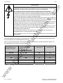
Von dieser Betriebsanleitung sind folgende fremdsprachige Ausgaben lieferbar:
These Operating Instructions are available in the following languages:
Französisch
French
Spanisch
Spanish
Italienisch
Italian
Bestell-Nr.
Order-No.
6SE7087-7AC85-0AA0
6SE7087-8AC85-0AA0
6SE7087-2AC85-0AA0
ca
lP
ar
tM
an
ua
ls
.c
Sprache
Language
lec
tri
Weitergabe sowie Vervielfältigung dieser Unterlage, Verwertung und
Mitteilung ihres Inhalts nicht gestattet, soweit nicht ausdrüchlich
zugestanden. Zuwiderhandlungen verpflichten zu Schadenersatz. Alle
Rechte vorbehalten, insbesondere für den Fall der Patenterteilung oder
GM-Eintragung.
SIMOVERT ® ist ein Warenzeichen von Siemens
.E
Wir haben den Inhalt der Druckschrift auf Übereinstimmung mit der
beschriebenen Hard- und Software überprüft. Dennoch können
Abweichungen nicht ausgeschlossen werden, so daß wir für die
vollständige Übereinstimmung keine Garantie übernehmen. Die Angaben
in dieser Druckschrift werden jedoch regelmäßig überprüft und
notwendige Korrekturen sind in den nachfolgenden Auflagen enthalten.
Für Verbesserungsvorschläge sind wir dankbar.
The reproduction, transmission or use of this document or its contents is
not permitted without express written authority. Offenders will be liable for
damages. All rights, including rights created by patent grant or registration
of a utility model or design, are reserved.
ww
w
We have checked the contents of this document for conformity with the
hardware and software described. However, this does not absolutely
preclude deviations, and we therefore cannot guarantee complete
conformity. The information in the document is subjected to regular
scrutiny. Any necessary corrections will be made in subsequent editions.
We also welcome any suggestions you may have in the way of
improvement.
© Siemens AG 1998 All rights reserved
SIMOVERT ® Registered Trade Mark
11.98
Inhalt
om
DEUTSCH
Inhalt
Seite
Definitionen ................................................................................................................ 0-5
1
Beschreibung ............................................................................................................ 1-1
1.1
Anwendungsbereich......................................................................................................... 1-1
1.2
Arbeitsweise..................................................................................................................... 1-1
2
Transportieren, Auspacken, Montieren .......................................................... 2-1
2.1
Transportieren, Auspacken .............................................................................................. 2-1
2.2
Lagern .............................................................................................................................. 2-1
2.3
Montieren ......................................................................................................................... 2-2
2.4
Maßbilder ......................................................................................................................... 2-3
3
Anschließen................................................................................................................ 3-1
3.1
Leistungsanschlüsse........................................................................................................ 3-2
3.2
Stromversorgung/Steuerung ............................................................................................ 3-4
3.2.1
Elektronikstromversorgung/Störmeldung......................................................................... 3-4
3.2.2
Melderelais X36 (Signal „Warnung“)................................................................................ 3-5
3.2.3
Einstellungen auf der Baugruppe A23 ............................................................................. 3-5
3.3
Steuerklemmleiste von Optionen ..................................................................................... 3-5
3.4
Maßnahmen zur Einhaltung der Funk-Entstörvorschriften .............................................. 3-7
3.5
Übersichtsschaltbilder mit Schaltungsvorschlägen.......................................................... 3-8
3.6
Leistungsteile ................................................................................................................... 3-10
ua
ls
an
ar
tM
lP
ca
lec
tri
4
Inbetriebnahme ......................................................................................................... 4-1
5
Leerkapitel
Leerkapitel
.E
6
7
.c
0
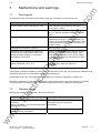
Störungen und Warnungen ................................................................................. 7-1
Störmeldungen................................................................................................................. 7-1
7.2
Warnmeldungen............................................................................................................... 7-1
ww
w
7.1
Siemens AG 6SE7087-6AC85-0AA0
Einspeise-Einheit Betriebsanleitung
DEUTSCH
0-3
Inhalt
11.98
Seite
Wartung ........................................................................................................................ 8-1
8-1
Wartungsempfehlungen ................................................................................................... 8-1
8.2
Austausch von Bauelementen ......................................................................................... 8-2
8.2.1
Austausch des Lüfters...................................................................................................... 8-2
8.2.2
Austausch von Baugruppen ............................................................................................. 8-2
8.2.3
Austausch von Brückengleichrichter V1........................................................................... 8-3
9
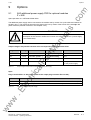
Optionen ...................................................................................................................... 9-1
9.1
A50 Zusatzstromversorgung PSR für Optionsbaugruppen.............................................. 9-1
9.2
Integrierbare Optionen in der Elektronikbox .................................................................... 9-2
9.3
Stromversorgung.............................................................................................................. 9-4
9.4
Stromistwerterfassung...................................................................................................... 9-4
9.5
Mechanik .......................................................................................................................... 9-6
10
Ersatzteile .................................................................................................................... 10-1
11
Leerkapitel
12
Leerkapitel
13
Umweltverträglichkeit ............................................................................................ 13-1
14
Technische Daten .................................................................................................... 14-1
14-1
Leistungsreduzierung bei erhöhter Kühlmitteltemperatur ................................................ 14-3
14.2
Leistungsreduzierung bei Aufstellhöhe > 1000m über NN .............................................. 14-3
14.3
Angewandte Normen........................................................................................................ 14-4
ww
w
.E
lec
tri
ca
lP
ar
tM
an
ua
ls
.c
om
8
0-4
DEUTSCH
Siemens AG 6SE7087-6AC85-0AA0
Einspeise-Einheit Betriebsanleitung
10.94
Definitionen
Definitionen
om
0
• QUALIFIZIERTES PERSONAL
.c
im Sinne der Betriebsanleitung bzw. der Warnhinweise auf dem Produkt selbst sind Personen, die mit
Aufstellung, Montage, Inbetriebsetzung und Betrieb des Produktes vertraut sind und über die ihrer Tätigkeit
entsprechenden Qualifikationen verfügen wie z. B.:
1. Ausbildung oder Unterweisung bzw. Berechtigung Stromkreise und Geräte gemäß den Standards der
Sicherheitstechnik ein- und auszuschalten, zu erden und zu kennzeichnen.
ua
ls
2. Ausbildung oder Unterweisung gemäß den Standards der Sicherheitstechnik in Pflege und Gebrauch
angemessener Sicherheitsausrüstung.
3. Schulung in Erster Hilfe
• GEFAHR
an
im Sinne dieser Betriebsanleitung und der Warnhinweise auf den Produkten selbst bedeutet, daß Tod,
schwere Körperverletzung oder erheblicher Sachschaden eintreten werden, wenn die entsprechenden
Vorsichtsmaßnahmen nicht getroffen werden.
• WARNUNG
ar
tM
im Sinne dieser Betriebsanleitung und der Warnhinweise auf den Produkten selbst bedeutet, daß Tod,
schwere Körperverletzung oder erheblicher Sachschaden eintreten können, wenn die entsprechenden
Vorsichtsmaßnahmen nicht getroffen werden.
• VORSICHT
im Sinne dieser Betriebsanleitung und der Warnhinweise auf den Produkten selbst bedeutet, daß eine
leichte Körperverletzung oder ein Sachschaden eintreten kann, wenn die entsprechenden
Vorsichtsmaßnahmen nicht getroffen werden.
lP
• HINWEIS
lec
tri
ca
im Sinne dieser Betriebsanleitung ist eine wichtige Information über das Produkt oder den jeweiligen Teil der
Betriebsanleitung, auf die besonders aufmerksam gemacht werden soll.
HINWEIS
.E
Diese Betriebsanleitung enthält aus Gründen der Übersichtlichkeit nicht sämtliche Detailinformationen zu
allen Typen des Produkts und kann auch nicht jeden denkbaren Fall der Aufstellung, des Betriebes oder der
Instandhaltung berücksichtigen.
Sollten Sie weitere Informationen wünschen, oder sollten besondere Probleme auftreten, die in der Betriebsanleitung nicht ausführlich genug behandelt werden, können Sie die erforderliche Auskunft über die örtliche
Siemens-Niederlassung anfordern.
ww
w
Außerdem weisen wir darauf hin, daß der Inhalt dieser Betriebsanleitung nicht Teil einer früheren oder bestehenden Vereinbarung, Zusage oder eines Rechtsverhältnisses ist oder dieses abändern soll. Sämtliche
Verpflichtungen von Siemens ergeben sich aus dem jeweiligen Kaufvertrag, der auch die vollständige und
allein gültige Gewährleistungsregelung enthält. Diese vertraglichen Gewährleistungsbestimmungen werden
durch die Ausführungen dieser Betriebsanleitung weder erweitert noch beschränkt.
Siemens AG 6SE7087-6AC85-0AA0
Einspeise-Einheit Betriebsanleitung
DEUTSCH
0-5
Definitionen
10.94
om
VORSICHT
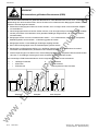
Elektrostatisch gefährdete Bauelemente (EGB)
.c
Das Gerät enthält elektrostatisch gefährdete Bauelemente. Diese Bauelemente können durch unsachgemäße
Behandlung sehr leicht zerstört werden. Wenn Sie dennoch mit elektronischen Baugruppen arbeiten müssen,
beachten Sie bitte folgende Hinweise:
♦ Elektronische Baugruppen sollten nur berührt werden, wenn es wegen daran vorzunehmender Arbeiten
unvermeidbar ist
ua
ls
♦ Wenn Baugruppen dennoch berührt werden müssen, muß der eigene Körper unmittelbar vorher entladen
werden (am besten durch Berühren eines geerdeten leitfähigen Gegenstands, z.B. eines Steckdosenschutzkontakts)
♦ Baugruppen dürfen nicht mit hochisolierenden Stoffen − z. B. Kunststoffolien, isolierenden Tischplatten,
Bekleidungsteilen aus Kunstfaser − in Berührung gebracht werden
an
♦ Baugruppen dürfen nur auf leitfähigen Unterlagen abgelegt werden
♦ Beim Löten an Baugruppen muß die Lötkolbenspitze geerdet werden
♦ Baugruppen und Bauelemente dürfen nur in leitfähiger Verpackung (z. B. metallisierten Kunststoffschachteln oder Metallbüchsen) aufbewahrt oder versandt werden
ar
tM
♦ Soweit Verpackungen nicht leitend sind, müssen Baugruppen vor dem Verpacken leitend umhüllt werden.
Hier kann z. B. leitfähiger Schaumgummi oder Haushalts-Alufolie verwendet werden.
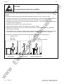
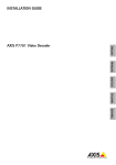
Die notwendigen EGB-Schutzmaßnahmen sind im folgenden Bild noch einmal verdeutlicht:
leitfähiger Fußboden
EGB-Tisch
EGB-Schuhe
=
=
=
EGB-Mantel
EGB-Armband
Erdungsanschluß der Schränke
d
d
lec
tri
b
d
e
f
lP
=
=
=
ca
a
b
c
e
e
f
f
c
a
Stehplatz
f
f
f
c
a
Steh-/Sitzplatz
ww
w
.E
Sitzplatz
a
d
b
0-6
DEUTSCH
Siemens AG 6SE7087-6AC85-0AA0
Einspeise-Einheit Betriebsanleitung
10.94
Definitionen
om
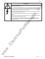
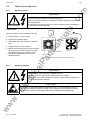
WARNUNG
Beim Betrieb elektrischer Geräte stehen zwangsläufig bestimmte Teile dieser Geräte
unter gefährlicher Spannung.
.c
Durch die Zwischenkreiskondensatoren in den angeschlossenen SIMOVERT Master
Drives ist bis zu 5 min nach dem Freischalten (Leistungsanschluß und Elektronikstromversorgung) gefährliche Spannung am Gerät vorhanden. Deshalb ist das Öffnen des
Gerätes erst nach einer Wartezeit von 5 min zulässig.
Bei Nichtbeachtung der Warnhinweise können Tod, schwere Körperverletzungen oder
erheblicher Sachschaden die Folge sein.
ua
ls
Nur entsprechend qualifiziertes Personal darf an diesem Gerät oder in dessen Nähe
arbeiten.
Dieses Personal muß gründlich mit allen Warnungen und Instandhaltungsmaßnahmen
gemäß dieser Betriebsanleitung vertraut sein.
ww
w
.E
lec
tri
ca
lP
ar
tM
an
Der einwandfreie und sichere Betrieb dieses Gerätes setzt sachgemäßen Transport,
fachgerechte Lagerung, Aufstellung und Montage sowie sorgfältige Bedienung und
Instandhaltung voraus.
Siemens AG 6SE7087-6AC85-0AA0
Einspeise-Einheit Betriebsanleitung
DEUTSCH
0-7
10.94
ww
w
.E
lec
tri
ca
lP
ar
tM
an
ua
ls
.c
om
Definitionen
0-8
DEUTSCH
Siemens AG 6SE7087-6AC85-0AA0
Einspeise-Einheit Betriebsanleitung
Beschreibung
1
Beschreibung
1.1
Anwendungsbereich
om
11.98
.c
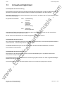
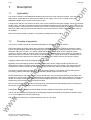
Die Einspeise-Einheit der Reihe SIMOVERT Master Drives ist ein Gerät der Leistungselektronik. Sie erzeugt
aus einem Drehstromnetz ein Gleichspannungsnetz und wird als Gleichspannungsspeiseeinheit für ein oder
mehrere Geräte der Wechselrichterreihe SIMOVERT Master Drives mit Spannungszwischenkreis verwendet.
1.2
an
Spannungs- und Strombereiche siehe technische Daten Kapitel 14.
ua
ls
An den Eingang wird ein Drehstromnetz angeschlossen. An den Gleichstrom-Ausgang können ein oder
mehrere Wechselrichter und ein Bremschopper angeschlossen werden. Dabei darf die Summe der
Bemessungsströme der installierten Wechselrichter den Bemessungsstrom der Einspeise-Einheit übersteigen.
Durch die Anlagenprojektierung ist jedoch sicherzustellen, daß zu keinem Zeitpunkt die Summe der
augenblicklichen Lastgleichströme größer als der Bemessungsgleichstrom der Einspeise-Einheit ist. Eine
Rückspeisung ins Netz ist nicht möglich.
Arbeitsweise
ar
tM
Die Einspeise-Einheit besteht aus einer 6-pulsigen Diodenbrücke zur Gleichrichtung des Drehstromnetzes.
lP
Die Vorladung beginnt ab dem Anlegen der Netzspannung durch Widerstände im Gleichstromzweig. Wenn die
Zwischenkreisspannung eine vorgegebene Einschaltschwelle überschreitet, werden die Vorladewiderstände
durch Relais überbrückt. Innerhalb der +10% und –15% Netzspannungstoleranz und bei richtiger Wahl der
Bemessungsanschlußpannung an den Wahlschaltern S1 und S3 und bei Beachtung der maximal möglichen
kapazitiven Belastung erfolgt die Vorladung innerhalb einer Sekunde. Die maximale Zwischenkreiskapazität
eines Gruppenantriebes darf die eines Einzelwechselrichters, dessen Bemessungsstrom im Zwischenkreis dem
Bemessungsstrom der Einspeise-Einheit entspricht, nicht übersteigen.
Eine Laststromentnahme während der Vorladung ist zu vermeiden!
ca
Wenn durch einen Netzausfall oder starken Netzeinbruch die Zwischenkreisspannung unter die Ausschaltschwelle sinkt, wird die Überbrückung der Vorladewiderstände wieder unterbrochen. Dadurch werden Überströme durch die zu schnelle Aufladung der Zwischenkreiskondensatoren bei Netzwiederkehr verhindert.
lec
tri
Ein Erdschluß am Ausgang eines angeschlossenen Umrichters wird von der Einspeise-Einheit nicht überprüft,
weil die dortigen Freilaufdioden durch die Vorladewiderstände ausreichend vor Überstrom geschützt sind.
Übertemperatur des Leistungsteiles, Übertemperatur der Vorladewiderstände, Phasenausfall und Elektronikversorgung werden überwacht und führen bei Gefahr zur Abschaltung und Fehlermeldung. Der Ausgangsstrom
wird nicht überwacht. Der Überstromschutz ist durch geeignete Dimensionierung und Betrieb der
angeschlossenen Wechselrichter sicherzustellen.
.E
Die Verwendung eines Hauptschützes oder einer ähnlich wirkenden Einrichtung, die durch das StörmeldungsRelais gesteuert wird, ist zum sicheren Betrieb der Einspeise-Einheit mit Vorladewiderständen notwendig.
Die Quittierung der Fehlermeldungen erfolgt durch Abschalten der Netzspannung oder der Elektronikversorgung.
w
Die Ein- und Ausschaltschwelle für die Überbrückung der Vorladewiderstände wird durch die Einstellung des
Wahlschalters S1 bzw. S3 auf der Baugruppe A23 festgelegt (siehe Inbetriebsetzung).
ww
Die Elektronikversorgung erfolgt extern durch einen DC 24 V Eingang.
Siemens AG 6SE7087-6AC85-0AA0
Einspeise-Einheit Betriebsanleitung
DEUTSCH
1-1
11.98
ww
w
.E
lec
tri
ca
lP
ar
tM
an
ua
ls
.c
om
Beschreibung
1-2
DEUTSCH
Siemens AG 6SE7087-6AC85-0AA0
Einspeise-Einheit Betriebsanleitung
11.98
Transportieren, Auspacken, Montieren
Transportieren, Auspacken, Montieren
2.1
Transportieren, Auspacken
om
2
.c
Die Geräte werden im Herstellerwerk entsprechend der Bestellung verpackt. Ein Produktverpackungsschild
befindet sich auf dem Karton.
Vermeiden Sie starke Transporterschütterungen und harte Stöße, z.B. beim Absetzen.
ua
ls
Beachten Sie die Hinweise auf der Verpackung für Transport, Lagerung und sachgemäße Handhabung.
Nach dem Auspacken und der Kontrolle auf Vollständigkeit der Sendung und Unversehrtheit des Gerätes
kann die Aufstellung erfolgen.
Die Verpackung besteht aus Karton und Wellpappe. Sie kann entsprechend den örtlichen Vorschriften für
Kartonagen entsorgt werden.
Lagern
ar
tM
2.2
an
Wenn Sie einen Transportschaden feststellen, sollten Sie umgehend Ihren Spediteur benachrichtigen.
ww
w
.E
lec
tri
ca
lP
Die Geräte müssen in sauberen trockenen Räumen gelagert werden. Temperaturen zwischen −25 °C (−13 °F)
und + 70 °C (158 °F) sind zulässig. Temperaturschwankungen > 20 K pro Stunde sind nicht zulässig.
Siemens AG 6SE7087-6AC85-0AA0
Einspeise-Einheit Betriebsanleitung
DEUTSCH
2-1
Transportieren, Auspacken, Montieren
Montieren
om
2.3
11.98
.c
Zur Befestigung werden benötigt:
♦ G-Schiene nach EN50035 mit Schrauben zur Befestigung
♦ eine Schraube M6
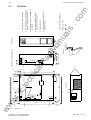
♦ Maßbild (Bild 2.2 für Bauform B, Bild 2.3 für Bauform C).
WARNUNG
ua
ls
Sicherer Betrieb des Gerätes setzt voraus, daß es von qualifiziertem Personal sachgemäß
unter Beachtung der Warnhinweise in dieser Betriebsanleitung montiert und in Betrieb
gesetzt wird.
Insbesondere sind sowohl die allgemeinen und nationalen Errichtungs- und Sicherheitsvorschriften für Arbeiten an Starkstromanlagen (z. B. VDE), als auch die den fachgerechten
Einsatz von Werkzeugen und die Benutzung persönlicher Schutzeinrichtungen
betreffenden Vorschriften zu beachten.
an
Bei Nichtbeachtung der Warnhinweise können Tod, schwere Körperverletzungen oder
erheblicher Sachschaden die Folge sein.
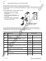
Anforderungen an den Aufstellort:
ar
tM
Das Gerät muß vor dem Eindringen von Fremdkörpern geschützt werden, da sonst
Funkton und Sicherheit nicht gewährleistet sind.
Für die Montage sind örtliche Richtlinien und Normen zu berücksichtigen.
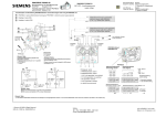
Verlustleistung
lP
Die Betriebsstätten müssen trocken und staubfrei sein. Die
zugeführte Luft darf keine funktionsgefährdenden, elektrisch
leitfähigen Gase, Dämpfe und Stäube enthalten. Staubhaltige Luft
muß gefiltert werden.
ca
WARNUNG
lec
tri
Schrankbelüftung entsprechend der Verlustleistung
dimensionieren! (Technische Daten Kapitel 14)
6SE70
.E
Das Umgebungsklima des Gerätes in den Betriebsräumen darf die
Werte des Kennbuchstabens 3K3 nach DIN IEC 721 Teil 3-3 /04.90
nicht überschreiten. Bei Temperaturen > 40 °C (104 °F) und Aufstellungshöhen >1000m, ist eine Leistungsreduzierung entsprechend
Kapitel: 14.1 und 14.2 erforderlich. Ab Aufstellhöhe >2000m ist auch
eine Anschlußspannungsreduzierung erforderlich.
Kühlluft
≤ 40 °C (50°C)
ww
w
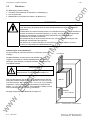
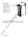
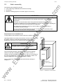
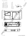
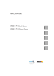
Montage entsprechend der Maßbilder in Kapitel 2.4.
2-2
DEUTSCH
Bild 2.1
Gerätemontage in Schaltschränken
Siemens AG 6SE7087-6AC85-0AA0
Einspeise-Einheit Betriebsanleitung
3)
4)
5)
40
50
1
2
X1
X37
S2
X36
R2
F2
F1
S3
S1
X1
X9
6)
X20
54321
X9
Draufsicht
350
Lufteintritt
V1
A23
Luftaustritt 2)
Z
A23
2)
D
67,5
V1
20
35
4)
135
Detail Z
1)
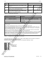
max. 5,7
.c
Maße: mm
Gewicht: ca. 12kg
om
Keine Schwerpunktverlagerung
6) Anschluß Stromversorgung DC24V
und Störmeldung
5) Berührungsschutz
4) Schirmanschlagstellen für Signalleitungen (2 Schirmschellen).
3) Notwendiger Luftraum zur Entwärmung
der Geräte.
2) Haken (Aufhängung) zur Befestigung
an einer G-Schiene nach EN50035
1) Durchgangsloch für Schraube M6.
ua
ls
DANGER
WARNUNG
SIEMENS
SIEMENS
Vorderansicht
an
ar
tM
X36
lP
S3
S1
X1
U1 V1 W1 PE C
47
Darstellung ohne Frontabgdeckung
ca
lec
tri
.E
125
6)
16
425
3)
100
425
100
Siemens AG 6SE7087-6AC85-0AA0
Einspeise-Einheit Betriebsanleitung
25
w
225
ww
23
41
Bild 2.2
R100
2.4
25
11.98
Transportieren, Auspacken, Montieren
Maßbilder
Bauform B
DEUTSCH
2-3
1)
DANGER
WARNUNG
SIEMENS
SIEMENS
L1
90
X1
U1
X9
L2
180
L3
V1 W1 PE
L+
C
L-
D
Z
34
56
4)
2)
R100
Luftaustritt
S2
A23
5)
Lufteintritt
DANGER
WARNUNG
V1
350
X1
2
126,7
47
52
100
3)
3)
om
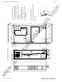
max. 5,7
Detail Z
.c
Maße: mm
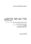
Gewicht: siehe Kapitel 14 (Technische Daten)
Keine Schwerpunktverlagerung
5) Anschluß Stromversorgung DC24V
und Störmeldung
4) Schirmanschlagstellen für Signalleitungen (2 Schirmschellen).
3) Notwendiger Luftraum zur Entwärmung
der Geräte.
2) Haken (Aufhängung) zur Befestigung
an einer G-Schiene nach EN50035
1) Durchgangsloch für Schraube M6.
ua
ls
an
A24
1
R2
F2
F1
S3
S1
X37
X20 X36
X9
5 4 3 2 1
X247
ar
tM
lP
ca
lec
tri
.E
82
69
54
23
43
16
600
Darstellung ohne Frontabgdeckung
25
DEUTSCH
X30.1
X30.2
2-4
600
Bild 2.3
100
w
ww
Transportieren, Auspacken, Montieren
11.98
Bauform C
Siemens AG 6SE7087-6AC85-0AA0
Einspeise-Einheit Betriebsanleitung
11.98
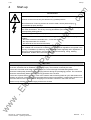
WARNUNG
Die Geräte werden mit hohen Spannungen betrieben.
Alle Anschlußarbeiten im spannungslosen Zustand durchführen!
om
Anschließen
.c
3
Anschließen
Alle Arbeiten am Gerät dürfen nur von qualifizierten Personen durchgeführt werden.
Bei Nichtbeachtung der Warnhinweise können Tod, schwere Körperverletzungen oder
erheblicher Sachschaden die Folge sein.
ua
ls
Durch die Zwischenkreiskondensatoren in den angeschlossenen SIMOVERT Master
Drives ist bis zu 5 min nach dem Freischalten noch gefährliche Spannung im Gerät
vorhanden. Deshalb ist das Öffnen des Gerätes erst nach einer entsprechenden Wartezeit
zulässig.
Auch bei Motorstillstand können die Leistungsklemmen und Steuerklemmen Spannung
führen.
an
Beim Hantieren am geöffneten Gerät ist zu beachten, daß spannungsführende Teile
freiliegen.
ar
tM
Der Benutzer ist dafür verantwortlich, daß E-Einheit, Umrichter, Motor und andere Geräte
nach den anerkannten technischen Regeln im Aufstellungsland (in der Bundesrepublik
Deutschland: VDE, VBG4), sowie anderen regional gültigen Vorschriften, aufgestellt und
angeschlossen werden. Dabei sind die Kabeldimensionierung, Absicherung, Erdung,
Abschaltung, Trennung und der Überstromschutz besonders zu berücksichtigen.
HINWEISE
lP
Bei der Auswahl der eingesetzten Komponenten sowie der Festlegung der Luft- und Kriechstrecken wurde auf
die Vorschriften der sicheren Trennung nach VDE 0160 / prEN 50178 geachtet.
ca
Es liegt im Ermessen des Anwenders dies bei der Auswahl der externen Stromversorgung ebenfalls zu
berücksichtigen.
ww
w
.E
lec
tri
Zum Betrieb der Geräte ist eine externe 24V-Stromversorgung erforderlich (siehe Kapitel 3.5 und 9.3)
Siemens AG 67087-6AC85-0AA0
Einspeise-Einheit Betriebsanleitung
DEUTSCH
3-1
Anschließen
Leistungsanschlüsse
om
3.1
11.98
WARNUNG
Durch falschen Netzanschluß kann das Gerät zerstört werden!
.c
Die Erregerspulen von Schützen und Relais, die am selben Netz wie das Gerät angeschlossen sind oder sich in der Nähe des Gerätes befinden, sind mit Überspannungsbegrenzern z.B. RC-Gliedern zu beschalten.
Das Gerät darf nicht über einen FI-Schutzschalter betrieben werden (DIN VDE 0160).
ua
ls
Das Gerät darf nur mit angeschlossenem SIMOVERT Master Drives an Spannung
geschaltet werden.
Durch Vertauschen oder Kurzschließen der Zwischenkreisklemmen wird der Umrichter
SIMOVERT Master Drives zerstört!
an
Die Geräte sind für festen Netzanschluß entsprechend DIN VDE 0160 Abschnitt 6.5.2.1 vorgesehen.
Schutzleiteranschluß: Mindestquerschnitt 10mm2.
ar
tM
Die Geräte sind auf der Netzseite mit Halbleiter-Sicherungen nach Tabelle 3.2
abzusichern. Um Netzrückwirkungen zu verringern und Oberschwingungen
zu begrenzen sollte der Netzanschluß über eine 2-%-Kommutierungsdrossel
nach Tabelle 3.3 erfolgen. Netz plus Kommutierungsinduktivität müssen ≥ 3%
uk sein (Wechselstrombelastbarkeit der Zwischenkreiskondensatoren im
Wechselrichter). Bestellnummern für Sicherungen siehe Tabelle 3.2.
Netz
Zwischenkreis
W1
C
V1 L3
L+
L2
PE
D
U1
LL1
lP
Die in Tabelle 3.1 angegebenen Anschlußquerschnitte sind für Kupferkabel
bei 40 °C (104 °F) Umgebungstemperatur ermittelt. Die Angaben erfolgen für
mehrdrähtige Kabel.
Klemmenanschlußbereich:
Bauform B: 2,5mm2 bis 16mm2 / AWG 14 bis AWG 6
X1
ca
Bild 3.1
Netzanschluß
Bauform C: 10mm2 bis 50mm2 / AWG 8 bis AWG 1/0
Bemessungs
eingangs-
Leiterquerschnitt
U1/L1, V1/L2, W1/L3
lec
tri
GeräteBestellnummer
Leiterquerschnitt
C/L+, D/L-
Leiterquerschnitt
PE
Spannung
Strom
(V)
(A)
mm2
AWG 1)
mm2
AWG 1)
mm2
AWG 1)
24-1EB85-0AA0
200 bis 480
36
16
6
16
6
16
6
28-6EC85-0AA0
200 bis 480
74
50
1/0
50
1/0
25
4
24-1FB85-0AA0
500 bis 600
36
16
6
16
6
16
6
.E
6SE70
27-2FC85-0AA0
500 bis 600
62
35
2
35
2
16
6
28-8FC85-0AA0
500 bis 600
82
50
1/0
50
1/0
25
4
Netzanschluß
ww
w
Tabelle 3.1
1) American Wire Gauge (Amerikanisches Drahtmaß)
3-2
DEUTSCH
Siemens AG 6SE7087-6AC85-0AA0
Einspeise-Einheit Betriebsanleitung
Anschließen
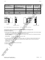
Sicherungen Netzzuleitung
6SE70
Spalte 1
Spalte 2
Spalte 3
Siemens gR
(SITOR)
Vorzugstyp
Siemens (SITOR)
Bussmann
US-Standard
A
Type
24-1EB85-0AA0
28-6EC85-0AA0
80
3NE1820-0
24-1FB85-0AA0
A
Type
A
Type
63
3NE4118
63
170M3610
125
3NE3222
125
170M3613
63
3NE4118
63
27-2FC85-0AA0
80
3NE1820-0
125
3NE3222
100
28-8FC85-0AA0
100
3NE1021-0
125
3NE3222
160
ua
ls
Bestellnummer
.c
Geräte-
om
11.98
170M3690
170M3692
170M3693
Empfohlene Netzsicherungen
Spalte 1:
Durch diese Sicherung mit gR-Charakteristik werden die Halbleiter geschützt. Sie haben auch
gleichzeitig Leitungsschutzcharakteristik, die bei entsprechender Anschlußquerschnittszuordnung
z.B. nach DIN VDE 0100 Teil 430 genutzt werden kann (bevorzugt einzusetzen).
an
Tabelle 3.2
Geräte-
Bemessungs-
Bestellnummer
eingangs-
ar
tM
Spalte 2, 3: Nur Halbleiterschutz, Leitungen werden nicht zuverlässig geschützt. Selektiver Leitungsschutz ist
durch Zuordnung der Leitungsschutzsicherung zu verlegtem Leitungsquerschnitt gemäß den
jeweils geltenden Vorschriften - z.B. DIN VDE 0100 Teil 430 - sicherzustellen.
Kommutierungsdrossel 2%
lP
Type
Spannung / Frequenz
Spannung Strom
(V)
(A)
ca
6SE70
Bemessungsstrom
(V / Hz)
(V / Hz)
(A)
200 bis 480
36
4EP3700-2UK
400 / 50
460 / 60
35,5
28-6EC85-0AA0
200 bis 480
74
4EP3900-2UK
400 / 50
460 / 60
80
24-1FB85-0AA0
500 bis 600
36
4EP3700-1UK
500 / 50
35,5
lec
tri
24-1EB85-0AA0
27-2FC85-0AA0
500 bis 600
62
4EP3900-1UK
500 / 50
63
28-8FC85-0AA0
500 bis 600
82
4EP4000-1UK
500 / 50
80
Empfohlene Kommutierungsdrossel
ww
w
.E
Tabelle 3.3
Siemens AG 67087-6AC85-0AA0
Einspeise-Einheit Betriebsanleitung
DEUTSCH
3-3
11.98
3.2
Stromversorgung / Steuerung
3.2.1
Elektronikstromversorgung / Störmeldung
om
Anschließen
Die Elektronikstromversorgung ist nicht im Lieferumfang der Einspeise-Einheit enthalten.
1
Funktion Beschreibung
zul. Leiterquerschnitt
(mm2)
(AWG)
DC 24V (Toleranzbereich 20V - 30V)
max. Stromaufnahme 2A bei +24V
0,2 bis 2,5
24 bis 14
Störmeldung
M
P
max. Stromaufnahme ohne Optionen:
Bauform B = 0,5A, Bauform C = 1A
1
2
Bezugspotential
0,2 bis 2,5
24 bis 14
3
nicht belegt (N.C.)
24 bis 14
4
Störmeldung
0,2 bis 2,5
24 bis 14
5
Störmeldung 2)
0,2 bis 2,5
24 bis 14
Zulässige Anschlußquerschnitte für Stromversorgung und Störmeldung
2
3
4
5
X9
an
0,2 bis 2,5
2)
Tabelle 3.4
ext. SV
DC 24V
ua
ls
Klemme
X9
.c
Steckklemme X9
Bild 3.2
AC 230V
1500VA
Anschluß Stromversorgung DC 24 V und
Störmeldung
ar
tM
Klemme X9.1 abgesichert mit Sicherung T2A/250V träge/time-lag 5x20mm
(19198-T2A/250V Fa. Wickmann-Werke GmbH bzw.
0034.3993 FSD Fa. Schurter)
lP
Klemme X9.2 abgesichert mit Sicherung T3,2A/250V träge/time-lag 5x20mm
(19198-T3,2A/250V Fa. Wickmann-Werke GmbH bzw.
0034.3998 FSD Fa. Schurter)
WARNUNG
ca
Aus Sicherheitsgründen wird empfohlen, netzseitig ein Hauptschütz oder eine gleichartig
funktionierende Einrichtung, die beim Öffnen des Kontaktes "Störung" das Gerät vom Netz
trennt, vorzusehen.
lec
tri
Um bei Verwendung eines Hauptschützes unerwartetes Einschalten nach Störungen zu
verhindern, ist die Schaltung eines Selbsthaltekreises für das Hauptschütz notwendig.
HINWEISE
Die Erregerspule des Hauptschützes ist mit Überspannungsbegrenzern z.B. RC-Glied bei AC bzw. Diode bei
DC zu beschalten.
.E
Den Relaiskontakt "Störung" (Klemme X9) ist direkt oder indirekt in die Hauptschütz-Steuerung einschleifen.
Die Verwendung eines Hauptschützes ist notwendig für den Schutz des Gerätes. Die Schaltung eines
Selbsthaltekreises verhindert unerwartetes Einschalten bei Wegfall der Störung.
ww
w
Ein Betrieb des Hauptschützes ohne Selbsthaltung führt bei Phasenausfall zum zyklischen Aus- und
Einschalten des Hauptschützes, weil bei Netzausfall die Phasenausfall-Meldung unterdrückt wird. Der
Netzausfall am Gerät entsteht durch den Abfall des Hauptschützes bei Störung.
2) Kontakte zum Schalten des Hauptschützes zwischen Klemme 4 und 5 ; Schaltspannung AC 230V max. AC 3A bei cosϕ ≥ 0,4;
max.Schaltleistung 1500 VA ; bei Schaltspannung DC 30V max. DC 5A
3-4
DEUTSCH
Siemens AG 6SE7087-6AC85-0AA0
Einspeise-Einheit Betriebsanleitung
11.98
Anschließen
3.2.2
Melderelais X36 (Signal „Warnung“)
zul. Leiterquerschnitt
(mm2)
(AWG)
Meldekontakte zum Schalten von Kleinspannung zwischen
Klemme 1 und 2 bei Schaltspannung DC 30 V max.DC 5 A, bei
Schaltspannung AC 60 V max. AC 5 A bei cosϕ ≥ 0,4
Tabelle 3.5
Warnung
3.2.3
Einstellungen auf der Baugruppe A23:
0,2 bis 2,5
24 bis 14
ua
ls
X36-1
X36-2
Funktion Beschreibung
.c
Klemmen
om
Steckklemme X36
an
R2: 0 Widerstand als Verbindung Erde - Masse M
Im Auslieferzustand ist M mit Erde verbunden. Entfernen dieses Widerstandes nur zur Vermeidung von
Störungen durch Erdschleifen, d.h. wenn die Elektronikmasse auf andere Weise (z.B. über den Masseanschluß
des Netzgerätes) mit Erde verbunden ist. Bei Einsatz der Zusatzstromversorgung A50 (siehe Kapitel 9.1) ist
zusätzlich der 0Ω Widerstand R210 auf der Baugruppe A50 zu entfernen.
ar
tM
S1: Mit S1 (Piano-DIP-Switch) die Bemessungsanschlußspannung einstellen (den zutreffenden Hebel zur
Baugruppe drücken). Es darf nur eine Spannung gewählt sein.
Die Einstellung der Anlagennetzspannung am Schalter S1 muß genau derjenigen an den angeschlossenen
Umrichtern entsprechen, um die richtige Reihenfolge von Überbrückung und Laststromentnahme zu
gewährleisten (siehe Kapitel 4, Tabelle 4.1 bzw. 4.2).
lP
S2: Mit S2 (DIP-Fix) kann der Zustand der Überbrückungsrelais auf den Ausgang "Warnung" (Klemme X36)
durchgeschaltet werden. Wenn S2 offen ist, wird nur bei Übertemperatur-Vorwarnung das Relais "Warnung"
geöffnet.
Steuerklemmenleiste von Optionen
VORSICHT
lec
tri
ca
3.3
Um die Steuerleitungen an X9, X36 und X37 anzuschließen, muß das Gerät im
spannungsfreien Zustand sein.
.E
♦ A50 Zusatzstromversorgung PSR für Optionsbaugruppen
Stecker X37
Stecker X37
w
Pin 1
Pin 2
ww
Tabelle 3.6
Funktion Beschreibung
DC 24V über eine Sicherung T2A mit Klemme X9-1 verbunden
Bezugspotential über eine Sicherung T3,2A mit Klemme X9-2 verbunden
Anschluß Zusatzstromversorgung
Siemens AG 67087-6AC85-0AA0
Einspeise-Einheit Betriebsanleitung
DEUTSCH
3-5
Anschließen
11.98
om
♦ Lüfter für Zusatzstromversorgung bei 36A-Geräten (6SE7024-1xB85)
(keine Kundenklemme)
Stecker X20
Funktion Beschreibung
Pin 1
DC 24V über einen gesteuerten Spannungsbegrenzer
Pin 2
Bezugspotential
Lüfteranschluß
ua
ls
Tabelle 3.7
.c
Stecker X20
♦ Anschluß von Steuerleitungen von Optionsbaugruppen(in Vorbereitung)
HINWEIS
an
Die Steuerleitungen müssen geschirmt sein und sind getrennt von den Leistungskabeln zu verlegen,
Mindestabstand 20 cm. Der Schirm ist beidseitig aufzulegen. Am Gerätegehäuse wird der Schirm mit
Schirmschellen aufgelegt, deren Handhabung in Bild 3.3 dargestellt ist.
ar
tM
Kreuzungen von Steuer- und Leistungskabeln sind in einem Winkel von 90° zu verlegen.
Schirmschelle einrasten
Kabelbinder
∅ ≤ 15mm
Stecker
∅ ≤ 7,5mm
∅ ≤ 5mm
lP
Schirmung überstülpen
und z.B. mit
Schrumpfschlauch
befestigen
ca
Länge nach
Bauform anpassen
lec
tri
Feder nicht
überbiegen
35
Schirmung
Schelle mit der Hand oder mit einem
Schraubenzieher zusammendrücken
und nach oben abziehen.
Vorsicht!
Die Schellen sind scharfkantig!
Anschließen der Steuerleitungen und Handhabung der Schirmschellen
.E
Bild 3.3
Schirmschelle lösen
Werden so viele Steuerleitungen benötigt, daß zwei Schirmschellen nicht ausreichen, so ist die Option „EMVSchirmgehäuse“ einzusetzen.
ww
w
Bestellnummer:
♦ Bauform B 6SE7090-0XB87-3CA0
♦ Bauform C 6SE7090-0XC87-3CA0
3-6
DEUTSCH
Siemens AG 6SE7087-6AC85-0AA0
Einspeise-Einheit Betriebsanleitung
11.98
Maßnahmen zur Einhaltung der Funk-Entstörvorschriften
Um Funk-Entstörvorschriften einhalten zu können müssen folgende Punkte beachtet werden:
om
3.4
Anschließen
ua
ls
.c
• Erdung
Bedingt durch die Arbeitsweise der Stromrichter entstehen Funkstörungen. Diese sollten möglichst niederohmig zur Quelle zurückgeführt werden (Querschnitt Erdungsanschluß ≥ Querschnitt Netzanschluß).
Benutzen Sie beim Einbau von Einspeiseeinheit und optionellen Funk-Entstörfiltern die beste Erdungsmöglichkeit (z.B. Montageblech, Erdungsseil, Erdungsschiene). Verbinden Sie alle leitfähigen Gehäuse
großflächig miteinander.
Für die Entstörung ist nicht nur der Querschnitt (Sicherheitsvorschriften im Fehlerfall beachten), sondern vor
allem die Oberfläche der Kontaktierung wichtig, da hochfrequente Störströme nicht durch den gesamten
Querschnitt, sondern weitgehend auf der Außenhaut eines Leiters fließen.
• Schirmung
Um Störungen zu reduzieren und die Funk-Entstörgrade einzuhalten, sind
− zwischen Umrichter-Ausgang und Motor geschirmte Kabel zu verwenden und
− geschirmte Steuerleitungen zu verlegen.
Der Schirm muß beidseitig mit Erdpotential verbunden werden.
an
• Filter
Die Entstörfilter müssen direkt vor der Einspeiseeinheit angeschlossen werden. Die Gehäuse müssen
leitend miteinander verbunden werden.
ww
w
.E
lec
tri
ca
lP
ar
tM
Zur Einhaltung der Funk-Entstörvorschriften werden A1-Entstörfilter empfohlen.
Siemens AG 67087-6AC85-0AA0
Einspeise-Einheit Betriebsanleitung
DEUTSCH
3-7
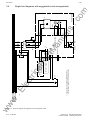
Bild 3.4
3-8
DEUTSCH
Aus
1) Lüfter nur bei Verwendung der A50 (C98043-A1699)
Zusatzstromversorgung PSR für Optionsbaugruppen
Ein
X36-2
X36-1
X9-5
X9-4
X9-3
X9-2
X9-1
X37-2
F1
M
A23
C98043-A1692
D/L-
GLR-
GLR+
X30-2
X20-1
+
X20-2
-
X30-1
U1/L1
V1/L2
W1/L3
ua
ls
an
+24V
X1: C/L+
Warnung
Störung
N.C.
F2
Filter
(optional)
X1: U1 V1 W1 PE
L1 L2 L3
ar
tM
X37-1
K1
+
1)
om
Leistungsteil
E1
M
.c
ϑ
R100
-
V1
3.5
24V-Netzgerät
lP
A50 (C98043-A1699)
Zusatzstromversorgung PSR
für Optionsbaugruppen
ca
lec
tri
.E
3AC 50-60Hz, 400V
3AC 50-60Hz, 500V
1AC 50-60Hz, 230V
w
ww
Anschließen
11.98
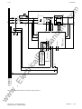
Übersichtschaltbilder mit Schaltungsvorschlägen
Übersichtsschaltbild mit Anschlußvorschlag, Bauform B
Siemens AG 6SE7087-6AC85-0AA0
Einspeise-Einheit Betriebsanleitung
w
ww
Bild 3.5
Siemens AG 67087-6AC85-0AA0
Einspeise-Einheit Betriebsanleitung
Ein
Aus
24V-Netzgerät
X36-2
X36-1
X9-5
X9-4
X9-3
X9-2
X9-1
X37-2
X37-1
A23
C98043-A1693
Warnung
+24V
M
K1
C/L+
D/L-
X247-1
X247-2
X30-2
X20-1
X20-2
GLR+
X30-1
Filter
(optional)
E1
M
DEUTSCH
X1: C/L+
PUD
NUD
-
V1
om
-
X1: D/L-
A24
PCU0
ϑ
R100
.c
+
+
X1: U1 V1 W1 PE
L1 L2 L3
X248-1
X248-2
ua
ls
+
-
U1/L1 V1/L2 W1/L3
an
Störung
N.C.
F2
F1
ar
tM
A50 (C98043-A1699)
Zusatzstromversorgung PSR
für Optionsbaugruppen
lP
ca
lec
tri
.E
3AC 50-60Hz, 400V
3AC 50-60Hz, 500V
1AC 50-60Hz, 230V
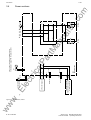
11.98
Anschließen
Übersichtsschaltbild mit Anschlußvorschlag, Bauform C
3-9
ϑ
R100
A50 (C98043-A1699)
Zusatzstromversorgung PSR
für Optionsbaugruppen
Warnung
Störung
24V-Netzgerät
X37-2
X37-1
X36-2
X36-1
X9-5
X9-4
X9-3
X9-2
X9-1
X30-1
X30-2
F1
T2A
-
K501-2
K440-2
-
X1: C/L+
+
+
~
~
X1: U1/
L1
~
~
C2
V1/
L2
~
~
W1/ PE
L3
ua
ls
an
ar
tM
lP
+
ca
+
X20-1
X20-2
A23
C98043-A1692
N.C.
F2
T3,2A
lec
tri
.E
Thermofühler
am Kühlkörper
M
E1
Lüfter nur bei Verwendung der A50 (C98043-A1699)
Zusatzstromversorgung PSR für Optionsbaugruppen
R712 R715
DEUTSCH
K701-2
3-10
K701-3
Bild 3.6
om
.c
-
-
V1
K702-3
X1: D/L-
R706 R709
3.6
K702-2
w
ww
Anschließen
11.98
Leistungsteile
Leistungsteil, Bauform B
Siemens AG 6SE7087-6AC85-0AA0
Einspeise-Einheit Betriebsanleitung
w
ww
ϑ
R100
A50 (C98043-A1699)
Zusatzstromversorgung PSR
für Optionsbaugruppen
Warnung
Störung
24V-Netzgerät
X37-2
X37-1
X36-2
X36-1
X9-5
X9-4
X9-3
X9-2
X9-1
X30-1
X30-2
F1
T2A
+
X20-1
X20-2
-
K501-2
K440-2
-
+
C/L+
D/L-
X247-2
X247-1
GLR+
U1/L1
V1/L2
W1/L3
X247-1
X248-2
X248-1
X247-2
X241
+
+
K4
~
X1: U1/
L1
ua
ls
an
ar
tM
lP
A23
C98043-A1693
N.C.
F2
T3,2A
ca
lec
tri
.E
Thermofühler
am Kühlkörper
X1: C/L+
PUD
X242
R423 R422 R421
M
K2
Siemens AG 67087-6AC85-0AA0
Einspeise-Einheit Betriebsanleitung
~
W1/ PE
L3
R411 R412 R413
X243
-
-
V1
X244
X1: D/L-
NUD
om
.c
C1
A24
PCU0
~
V1/
L2
K1
Bild 3.7
K3
E1
11.98
Anschließen
Leistungsteil, Bauform C
DEUTSCH
3-11
11.98
ww
w
.E
lec
tri
ca
lP
ar
tM
an
ua
ls
.c
om
Anschließen
3-12
DEUTSCH
Siemens AG 6SE7087-6AC85-0AA0
Einspeise-Einheit Betriebsanleitung
11.98
Inbetriebnahme
om
4
Inbetriebnahme
WARNUNG
.c
Die Geräte 6SE70 werden mit hohen Spannungen betrieben.
Alle Arbeiten am Gerät dürfen nur von qualifizierten Personen durchgeführt werden.
Bei Nichtbeachtung der Warnhinweise können Tod, schwere Körperverletzungen oder
erheblicher Sachschaden die Folge sein.
ua
ls
Durch die Zwischenkreiskondensatoren ist bis zu 5 min nach dem Freischalten noch
gefährliche Spannung im Gerät vorhanden. Deshalb ist das Öffnen des Gerätes erst nach
einer entsprechen Wartezeit zulässig.
Beim Hantieren am geöffneten Gerät ist zu beachten, daß spannungsführende Teile
freiliegen.
an
Auch bei Motorstillstand können folgende Geräteteile Spannung führen:
- die Netzanschlußklemmen U1/L1, V1/L2 und W1/L3
- die Ausgangsklemmen C/L+ und D/L- die Klemmen der Steuerklemmenleiste
lP
ar
tM
Der Benutzer ist dafür verantwortlich, daß E-Einheit, Umrichter, Motor, und andere Geräte
nach den anerkannten technischen Regeln im Aufstellungsland (in der Bundesrepublik
Deutschland: VDE, VBG4), sowie anderen regional gültigen Vorschriften, aufgestellt und
angeschlossen werden. Dabei sind die Kabeldimensionierung, Absicherung, Erdung,
Abschaltung, Trennung und der Überstromschutz besonders zu berücksichtigen.
HINWEIS
ca
Wenn zwischen dem Sternpunkt des Netzes (Erde) und Zwischenkreis große Kapazitäten liegen (Störableitkondensatoren), und der Zwischenkreis unbelastet ist, kann sich dieser um √2 höher aufladen als im
Normalfall.
lec
tri
Bei Erdschluß am Umrichterausgang wird der Strom über die Freilaufdioden der Umrichter durch die Vorladewiderstände beim Vorladen hinreichend begrenzt. Die angeschlossenen Umrichter erkennen von sich aus
Erdschlüsse bei Betrieb des Wechselrichters.
Ein Betrieb des Hauptschützes ohne Selbsthaltung führt bei Phasenausfall zum zyklischen Aus- und
Einschalten des Hauptschützes, weil bei Netzausfall die Phasenausfall-Meldung unterdrückt wird. Der
Netzausfall am Gerät entsteht durch den Abfall des Hauptschützes bei Störung.
ww
w
.E
Der Lüfter wird nur bei kurzgeschlossenen Vorladewiderständen eingeschaltet.
Siemens AG 6SE7087-6AC85-0AA0
Einspeise-Einheit Betriebsanleitung
DEUTSCH
4-1
Inbetriebnahme
11.98
om
WARNUNG
Die Einstellung der Bemessungsanschlußspannung am Schalter S1 muß genau der
eingestellten Spannung an den angeschlossenen Umrichtern entsprechen, um die richtige
Reihenfolge von Überbrückung und Laststromentnahme zu gewährleisten.
.c
Bei zu hoher Einstellung der Bemessungsanschlußspannung wird das Ende der
Vorladung dann nicht erreicht, wenn einer der angeschlossenen Umrichter hinreichend
Laststrom zieht. Dadurch werden die Vorladewiderstände überhitzt und das Gerät schaltet
mit "Störung" ab. Ebenso öffnen die Überbrückungsrelais bei Netzeinbrüchen zu früh und
können durch Gleichstrom-Lichtbögen beschädigt werden.
ua
ls
Bei zu niedriger Einstellung der Bemessungsanschlußspannung werden die Vorladewiderstände zu früh überbrückt und es entsteht ein Überstromimpuls, der zur Beschädigung des
Gleichrichters, der Relaiskontakte und der Sicherungen führen kann.
Pluspol und Minuspol (C/L+ und D/L-) des Zwischenkreises sind bei parallelen Umrichtern
unbedingt richtig anzuschließen, weil die dortigen Freilaufdioden durch die Sicherungen
der E-Einheit vor Überstrom nicht hinreichend abgesichert sind.
an
Ein Betrieb ohne Hauptschütz oder eine gleichartig funktionierende Einrichtung, die beim
Öffnen des Kontaktes "Störung" das Gerät vom Netz trennt, ist unzulässig und kann zur
Beschädigung des Gerätes führen.
Um unerwartetes Einschalten nach Störungen zu verhindern ist die Schaltung eines
Selbsthaltekreises für das Hauptschütz notwendig.
ar
tM
Mit den Schaltern S1 bzw. S3 muß eine Spannung ausgewählt sein, sonst kommt es zum
Sicherungsfall.
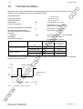
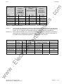
Die Vorladung beginnt ab Anlegen der Netzspannung und wird, wenn Ud die Einschaltschwelle überschreitet
durch Überbrücken der Vorladewiderstände beendet.
ca
Zwischenkreisspannungsnennwerte Und in V= bei
Nennlast
(am SIMOVERT Master Drive
Parameter P071 einstellen)
605
lec
tri
Bemessungs
anschlußspannung Un
verkettet in Veff (A.C.)
lP
Wenn Ud die Ausschaltschwelle unterschreitet wird die Überbrückung der Vorladewiderstände beendet, und
das Gerät befindet sich wieder im Vorladezustand.
460 / 480
Ausschaltschwelle
von Ud in V=
508
419
578
486
400
415
545
458
378
400
526
442
364
380
500
420
346
230
302
254
209
200
263
220
181
.E
440
Einschalt- und Ausschaltschwellen für Geräte 6SE70xx-xEx8x
ww
w
Tabelle 4.1
Einschaltschwelle
von Ud in V=
4-2
DEUTSCH
Siemens AG 6SE7087-6AC85-0AA0
Einspeise-Einheit Betriebsanleitung
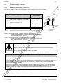
Inbetriebnahme
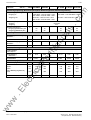
600
663
546
575
756
635
525
690
580
500
657
552
Einschalt- und Ausschaltschwellen für Geräte 6SE70xx-xFx8x
L2
600
575
525
500
-----
S1
S1
S3
1
2
3
4
5
6
S1
ar
tM
1 0
Bauform B
523
478
455
L1
460
440
415
400
380
230
L2
600
575
525
500
-----
S3
6
5
4
3
2
1
S1
0 1
Bauform C
Lage auf A23
Bild 4.1
Ausschaltschwelle
von Ud in V=
ua
ls
L1
460
440
415
400
380
230
Einschaltschwelle
von Ud in V=
an
Tabelle 4.2
Zwischenkreisspannungsnennwerte Und in V=
(am SIMOVERT Master Drive
Parameter P071 einstellen)
789
.c
Bemessungs
anschlußspannung Un
verkettet in Veff (A.C.)
om
11.98
Wahlschalter S1 und S3 auf Baugruppe A23
Lage auf A23
460V- Stellung auch für 480V, S3 für 200V
lP
Nach Anschluß des Gerätes (laut Kapitel 3) sind folgende Inbetriebnahmeschritte durchzuführen:
ca
♦ Mit Schalter S1 (Piano-DIP-Switch) ist die Bemessungsanschlußspannung einzustellen (den
entsprechenden Hebel des Schalters zur Baugruppe drücken). Es darf nur eine Spannung gewählt sein
(auch S3 offen).
Der Spannungsbereich 200V wird durch Schließen der DIP-Fix Schaltbrücke S3 (über S1) aktiviert, dabei
müssen alle Hebel von S1 offen sein.
lec
tri
Werkseinstellung: bei 200-230V und 380-480V- Geräten = 400V
bei 500-600V-Geräten = 500V
♦ Mit Schaltbrücke S2 (DIP-Fix) kann der Zustand der Überbrückungsrelais auf den Ausgang "Warnung"
(Klemme X36) durchgeschaltet werden. Wenn S2 offen ist, wird nur bei Übertemperatur-Vorwarnung das
Relais "Warnung" geöffnet.
Werkseinstellung: S2 offen
♦ Netz und Elektronik-Versorgung einschalten.
ww
w
.E
♦ Umrichter freigeben.
Siemens AG 6SE7087-6AC85-0AA0
Einspeise-Einheit Betriebsanleitung
DEUTSCH
4-3
11.98
ww
w
.E
lec
tri
ca
lP
ar
tM
an
ua
ls
.c
om
Inbetriebnahme
4-4
DEUTSCH
Siemens AG 6SE7087-6AC85-0AA0
Einspeise-Einheit Betriebsanleitung
11.98
Störungen und Warnungen
Störungen und Warnungen
7.1
Störmeldungen
om
7
.c
Störungs-Relais K440 an Klemmen X9-4 und X9-5 unterbricht. Es erfolgt im Gerät keine Speicherung des
Fehlers.
Abhilfe
Elektronikversorgung ist kleiner als DC 18 V
Elektronikversorgung 20 bis 30 V überprüfen,
Sicherungen F1 und F2 überprüfen.
keine Bemessungsanschlußspannung an S1/S3
gewählt
Ein Hebel an S1 muß zur Leiterplatte hin gedrückt
sein oder der Dip-Switch S3 muß geschlossen
sein.
mehrere Bemessungsanschlußspannungen an
S1 gewählt
Nur ein Hebel an S1 darf zur Leiterplatte hin
gedrückt sein, wenn der Dip-Switch S3 offen ist.
Kein Hebel an S1 darf zur Leiterplatte gedrückt
sein, wenn der Dip-Switch S3 geschlossen ist.
Phasenausfall länger als 1 Sekunde
Netz überprüfen.
Überlastung der Vorladewiderstände durch zu
große Zwischenkreiskapazität oder Laststromentnahme während der Vorladung oder zu
häufige Vorladung innerhalb kurzer Zeit
Bemessungsanschlußspannung an S1/S3 und
allen angeschlossenen Umrichtern richtig
einstellen, Koordination des Aufbaues der
Zwischenkreisspannung und der
Laststromentnahme sowie Summe der
Zwischenkreiskapazitäten überprüfen.
Übertemperatur des Leistungsteiles
Schaltschwelle = 90°C ±5°C
Stromentnahme reduzieren, Luftdurchsatz (Lüfter)
überprüfen, Zulufttemperatur überprüfen.
lP
ar
tM
an
ua
ls
Mögliche Ursache
ca
Wenn einer dieser Fehler auftritt, wird sofort Fehlermeldung über K440 gegeben (das Gerät muß darauffolgend
3-phasig vom Netz getrennt werden). Der Fehler wird vom Gerät nicht gespeichert oder angezeigt.
Es wird empfohlen das Hauptschütz gemäß Anschlußvorschlag Kapitel 3.5 zu verdrahten.
7.2
lec
tri
Eine Quittierung des Fehlers erfolgt durch Fehlerquittierung am Selbsthaltekreis des Hauptschützes oder einer
ähnlich wirkenden Einrichtung. Nach Anlegen der Netzspannung beginnt sofort wieder die Vorladung.
Warnmeldungen
Warnungs-Relais K501 an Klemmen X36-1 und X36-2 unterbricht.
.E
Ursache
Abhilfe
Übertemperatur des Leistungsteiles Vorwarnung Stromentnahme reduzieren, Luftdurchsatz
Schaltschwelle = 6°C unter der für Störmeldung überprüfen, Zulufttemperatur überprüfen
(90°C ±5°C)
DIP-FIX-Schalter S2 öffnen.
ww
w
Wenn der DIP-FIX-Schalter S2 geschlossen ist,
erfolgt auch eine Warnung während der
Vorladung.
Siemens AG 6SE7087-6AC85-0AA0
Einspeise-Einheit Betriebsanleitung
DEUTSCH
7-1
11.98
ww
w
.E
lec
tri
ca
lP
ar
tM
an
ua
ls
.c
om
Störungen und Warnungen
7-2
DEUTSCH
Siemens AG 6SE7087-6AC85-0AA0
Einspeise-Einheit Betriebsanleitung
02.96
Wartung
om
8
Wartung
WARNUNG
Die Geräte SIMOVERT Master Drives werden mit hohen Spannungen betrieben.
.c
Alle Arbeiten am Gerät müssen in Übereinstimmung mit den nationalen elektrischen Bestimmungen (Bundesrepublik Deutschland: VBG 4) durchgeführt werden.
Wartungs- und Instandhaltungsarbeiten dürfen nur von qualifiziertem Personal
durchgeführt werden.
ua
ls
Nur vom Hersteller zugelassene Ersatzteile dürfen verwendet werden.
Die vorgeschriebenen Wartungsintervalle sowie die Anweisungen für Reparatur und Austausch sind unbedingt einzuhalten.
an
Durch die Zwischenkreiskondensatoren ist bis zu 5 min nach dem Freischalten (Leistungsanschluß und Elektronikstromversorgung) noch gefährliche Spannung im Gerät
vorhanden. Deshalb ist das Öffnen des Gerätes erst nach einer entsprechen Wartezeit
zulässig.
Auch bei Motorstillstand können die Leistungsklemmen und Steuerklemmen Spannung
führen.
ar
tM
Wenn Arbeiten am eingeschalteten Gerät notwendig sind:
♦ berühren Sie keine spannungsführende Teile.
♦ benutzen Sie nur ordnungsgemäße meßtechnische Ausrüstungen und Arbeitsschutzkleidung.
♦ stellen Sie sich auf eine nicht geerdete, isolierte und EGB-gerechte Unterlage.
lP
Bei Nichtbeachtung der Warnhinweise können Tod, schwere Körperverletzungen oder
erheblicher Sachschaden die Folge sein.
Wartungsempfehlungen
lec
tri
8.1
ca
Bei Fragen an die Serviceabteilung sollten Sie Bestell- und Fabrik-Nr. Ihres Gerätes wissen. Sie finden diese
Nummern und andere wichtige Daten auf dem Leistungsschild des Gerätes.
Staubablagerungen im Gerät müssen von qualifiziertem Personal mindestens einmal im Jahr gründlich entfernt
werden. Bei Bedarf muß die Reinigung in kürzeren Zeitabständen erfolgen. Die Reinigung muß mit Pinsel und
Staubsauger und an nicht zugänglichen Stellen mit staubfreier trockener Druckluft, max. 1 bar erfolgen.
ww
w
.E
Der DC-24V-Lüfter ist für eine Betriebsdauer von 35 000 Stunden bei einer Umgebungstemperatur von 40 °C
ausgelegt. Er muß rechtzeitig ausgewechselt werden, um die Verfügbarkeit des Gerätes zu erhalten.
Siemens AG 6SE7087-6AC85-0AA0
Einspeise-Einheit Betriebsanleitung
DEUTSCH
8-1
02.96
8.2
Austausch von Bauelementen
8.2.1
Austausch des Lüfters
om
Wartung
WARNUNG
.c
Der Lüfter darf nur von qualifiziertem Personen ausgetauscht werden.
ua
ls
Durch die Zwischenkreiskondensatoren ist auch nach dem Freischalten noch
für 5 min gefährliche Spannung vorhanden.
Bei Nichtbeachtung der Warnhinweise können Tod, schwere Körperverletzungen oder erheblicher Sachschaden die Folge sein.
Bauform B und C
Der Lüfter befindet sich an der Unterseite des
Gerätes
X20
♦ Beide Torx-Schrauben M4 x 49 lösen
M4 x 49
Torx T20
an
♦ Schutzgitter entfernen
♦ Neuen Lüfter in umgekehrter Reihenfolge
einbauen
ar
tM
♦ Lüfter nach unten herausziehen und Stecker
X20 abziehen
Lüfter E1
M4 x 49 / Torx T20
Bild 8.1
Schutzgitter und Lüfter (24 V) für Bauform B und C
ca
lP
♦ Vor Inbetriebnahme des Gerätes Lüfter auf
Schleiffreiheit und Strömungsrichtung der Luft
(Pfeil nach oben) überprüfen. Die Luft muß
nach oben aus dem Gerät abgeführt werden.
Schutzgitter
Austausch von Baugruppen
lec
tri
8.2.2
WARNUNG
Die Baugruppen dürfen nur von qualifizierten Personen ausgetauscht werden.
Die Baugruppen dürfen nicht unter Spannung gezogen oder gesteckt werden.
Bei Nichtbeachtung dieser Warnhinweise können Tod, schwere Körperverletzung oder erheblicher Sachschaden die Folge sein.
.E
VORSICHT
ww
w
Die Baugruppen enthalten elektrostatisch gefährdete Bauelemente. Vor dem Berühren
einer elektronischen Baugruppe muß der eigene Körper entladen werden. Dies kann in
einfachster Weise dadurch geschehen, daß unmittelbar vorher ein leitfähiger, geerdeter
Gegenstand berührt wird (z. B. metallblanke Schaltschrankteile).
8-2
DEUTSCH
Siemens AG 6SE7087-6AC85-0AA0
Einspeise-Einheit Betriebsanleitung
02.96
Wartung
S te c k p la tz 1 (P S R )
S te c kp la tz 3 (O p tio n e n )
S te c k p la tz 2 (O p tio n e n )
ua
ls
♦ Baugruppe mit Hilfe der Steck- /
Ziehhilfen vorsichtig aus der
Elektronikbox herausziehen, dabei
beachten, daß sich die Baugruppe
nicht verhakt
.c
♦ Befestigungsschrauben der
Baugruppen oberhalb und unterhalb
der Steck- / Ziehhilfen lösen
om
Tausch von Baugruppen in der
Elektronikbox (Optionen)
♦ Neue Baugruppe vorsichtig in den
Führungsschienen bis zum Anschlag
in die Elektronikbox einschieben
ar
tM
an
♦ Baugruppe mit den
Befestigungsschrauben oberhalb und
unterhalb der Steck- / Ziehhilfen
festschrauben.
Bild 8.2
Elektronikbox, bestückt mit PSR (Steckplatz 1)
Austausch von Brückengleichrichter V1
ca
8.2.3
lP
und Optionen (Steckplatz 2 und 3)
ww
w
.E
lec
tri
Der Brückengleichrichter ist mit selbstfurchenden Schrauben befestigt. Bei Austauch sind zur Befestigung des
Brückengleichrichters unbedingt Schrauben in Originallänge mit Sicherungselementen zu verwenden.
Bei der Verschraubung des Brückengleichrichters mit den Anschlußkabel sind ebenfalls Schrauben mit
Originallänge zu verwenden.
Siemens AG 6SE7087-6AC85-0AA0
Einspeise-Einheit Betriebsanleitung
DEUTSCH
8-3
02.96
ww
w
.E
lec
tri
ca
lP
ar
tM
an
ua
ls
.c
om
Wartung
8-4
DEUTSCH
Siemens AG 6SE7087-6AC85-0AA0
Einspeise-Einheit Betriebsanleitung
Optionen
9
Optionen
9.1
A50 Zusatzstromversorgung PSR für Optionsbaugruppen
Z = K90
.c
Ersatzteil-Bestellnummer: 6SE7090-0XX85-0KA0
om
11.98
ua
ls
Die Zusatzstromversorgung A50 ist mit der Baugruppe A23 durch ein 2-poliges Kabel verbunden und links im
Einbauplatz 1 eingesteckt. Die Baugruppe ist durch die Schrauben der Ziehhilfe an der Elektronikbox befestigt
(Verbindung Erde-Masse siehe Kapitel 3.2.3).
VORSICHT
an
Die maximal entnehmbare Leistung ist in Summe 19 Watt (mit Rücksicht auf den
maximalen Verbrauch der Einspeise-Einheit und der gemeinsamen Sicherung mit 2 A für
die DC 24 V Versorgung auf der Baugruppe A23).
Bezeichnung
Spannung
Strom
Überlastschutz
Toleranz
Strombegrenzung
± 2%
0 bis 0,8A (0,65A 1) )
Strombegrenzung
± 3%
-15 V
0 bis 0,33A (0,3A 1) )
Strombegrenzung
± 3%
+24 V
0 bis 0,2A
+5 V
0 bis 3,5A
P15
+15 V
N15
P24_AUX
Heißleiter, Thermistor
lP
P5
Entspricht der DC 24V
Versorgung
Ausgangsspannungen und mögliche Ströme der Zusatzstromversorgung
ca
Tabelle 9.1
ar
tM
Ausgangsspannungen und mögliche Ströme an den entsprechenden Stiften von Stecker X107:
lec
tri
Eingang:
Steckklemme X37 auf der A50 (entspricht dem Ausgang Stiftleiste X37 auf derA23):
Klemme
1
2
DC 24V Versorgung Toleranz: 20V - 30V (auf Baugruppe A23 mit T2A abgesichert)
Bezugspotential (auf Baugruppe A23 mit T3,2A abgesichert)
Anschluß der Zusatzstromversorgung
ww
w
.E
Tabelle 9.2
Funktion Beschreibung
1) maximaler Laststrom beim Einschalten
Siemens AG 6SE7087-6AC85-0AA0
Einspeise-Einheit Betriebsanleitung
DEUTSCH
9-1
Optionen
Integrierbare Optionen in der Elektronikbox
om
9.2
11.98
Local Bus Adapter (LBA) zum Einbau von optionalen Zusatzbaugruppen
.c
Voraussetzung für den Einbau von Optionalen Zusatzbaugruppen ist die Option LBA. Wenn der LBA noch nicht
im Gerät vorhanden ist, muß er in die Elektronikbox eingebaut werden, bevor man eine Optionsbaugruppe
einschieben kann.
Local Bus Adapter LBA in der Elektronikbox montieren:
ua
ls
♦ PSR-Baugruppe nach Lösen der beiden
Befestigungsschrauben an den Ziehgriffen
herausnehmen.
♦ Buserweiterung LBA in Elektronikbox
schieben (Lage siehe nebenstehendes Bild)
und einrasten.
ar
tM
an
♦ PSR-Baugruppe wieder in linken Steckplatz
einstecken und Befestigungsschrauben an
den Ziehgriffen anschrauben.
Steckplatz 2 (Optionen)
Steckplatz 3 (Optionen)
Steckplatz 1 (PSR)
Für die Verwendung der Baugruppen CBC und CBP ist zusätzlich zum LBA noch ein ADB (Adapter Board,
Trägerboard) notwendig. Diese Baugruppen müssen aufgrund der kleineren mechanischen Abmessungen auf
ein ADB gesteckt werden, damit sie in die Elektronikbox gesteckt werden können.
lP
Die Optionen werden mit Optionsbeschreibung geliefert.
Beschreibung
LBA
Local-Bus-Adapter für die Elektronikbox.
Voraussetzung für den Einbau von T300, CB1, SCB1
und SCB2
ADB
Adapter Board für kleine Baugruppen
Voraussetzung für den Einbau von CBC und CBP
Baugruppe
T100
Technologiebaugruppe
Baugruppe
6SE7090-0XX87-0BB0
Beschreibung 6SE7080-0CX87-0BB0
T300
Technologiebaugruppe zur Regelung technologischer
Vorgänge
Baugruppe
6SE7090-0XX84-0AH0
Beschreibung 6SE7080-0CX84-0AH0
SCB1
Serielle Kommunikationsbaugruppe mit
Lichtwellenleiter für serielles I/O-System und Peer-toPeer-Verbindung
Baugruppe
6SE7090-0XX84-0BC0
Beschreibung 6SE7080-0CX84-0BC0
SCB2
Serielle Kommunikationsbaugruppe für Peer-to-Peer
Verbindung und USS-Protokoll über RS485
6SE7090-0XX84-0BD0
Baugruppe
Beschreibung 6SE7080-0CX84-0BD0
Anwendung der seriellen Schnittstelle mit USSProtokoll
Applikationsbeschreibung
w
.E
lec
tri
ca
Bezeichnung
ww
CB1
9-2
Bestellnummer
Baugruppe
6SE7090-0XX84-4HA0
Beschreibung 6SE7080-0CX84-4HA0
6SE7087-6CX87-4KB0
Kommunikationsbaugruppe mit Schnittstelle für SINEC- Baugruppe
6SE7090-0XX84-0AK0
L2-DP, (Profibus)
Beschreibung 6SE7087-0CX84-0AK0
Anwendung der Profibus-DP-Schnittstelle
DEUTSCH
Applikationsbeschreibung
6SE7087-6CX87-0AK0
Siemens AG 6SE7087-6AC85-0AA0
Einspeise-Einheit Betriebsanleitung
11.98
Optionen
Beschreibung
CB2
Kommunikationsbaugruppe mit Schnittstelle für CANProtokoll
CBP
Kommunikationsbaugruppe mit Schnittstelle für SINEC- Baugruppe
L2-DP, (Profibus) (kleinformatige Baugruppe; muß am
ADB rechts bzw. unten gesteckt werden)
CBC
Kommunikationsbaugruppe mit Schnittstelle für CANProtokoll (kleinformatige Baugruppe; muß am ADB
rechts bzw. unten gesteckt werden)
Optionsbaugruppen und Busadapter
Baugruppe
6SE7090-0XX84-0AE0
Beschreibung 6SE7087-6CX84-0AK0
.c
Baugruppe
6SE7090-0XX84-0FF0
6SE7090-0XX84-0FG0
ua
ls
Tabelle 9.3
Bestellnummer
om
Bezeichnung
Baugruppen
Links
Steckplatz 1 (PSR)
PSR
Mitte
Steckplatz 3 (Optionen)
CB1 / SCB1 / SCB2 / CBC (mit ADB) / CBP (mit ADB)
Rechts
Steckplatz 2 (Optionen)
CB1 / CB2 / CBP (mit ADB) / CBC (mit ADB) / SCB1 / SCB2
/ T100 / T300
an
Steckplatz in der Elektronikbox
HINWEIS
ar
tM
Wenn nur eine Technologiebaugruppe eingesetzt wird, muß diese immer in Steckplatz 2 der Elektronikbox
gesteckt werden.
Jede optionale Zusatzbaugruppe darf nur einmal in der Elektronikbox montiert sein.
Wird eine Technologiebaugruppe zusammen mit einer Kommunikationsbaugruppe verwendet, dann muß
die Kommunikationsbaugruppe im Slot G (kleinformatige Baugruppen CBP und CBC) bzw. im Steckplatz 3
(großformatige Baugruppen CB1 und CB2) stecken.
lP
Die Daten von großformatigen Baugruppen erscheinen immer unter Slot E bzw. Slot G, d.h. daß z.B. die
Softwareversion einer Technologiebaugruppe über r060.003 angezeigt wird.
ca
Für die Verwendung von kleinformatigen Baugruppen (CBP und CBC) ist zusätzlich zum LBA noch ein ADB
(Adapter Board, Trägerboard) notwendig. Diese Baugruppen müssen aufgrund der kleinen mechanischen
Abmessungen auf ein ADB gesteckt werden, damit sie in die Elektronikbox gesteckt werden können.
Es können maximal 2 Zusatzbaugruppen verwendet werden.
Steckplätze für die Optionsbaugruppen in der Elektronikbox
lec
tri
Tabelle 9.4
In der Elektronikbox können mit Hilfe der Option LBA (Local Bus Adapter) eine oder zwei der in Tabelle 9.3
aufgeführten Optionsbaugruppen gesteckt werden.
Die Kennzeichnung der Steckplätze bzw. Slots ist in der folgenden Abbildung zu sehen.
3
2
.E
1
D
G
E
Kennzeichnung der
Steckplätze 1 bis 3
und Slots D bis G
in der Elektronikbox
ww
w
PSR
F
Siemens AG 6SE7087-6AC85-0AA0
Einspeise-Einheit Betriebsanleitung
DEUTSCH
9-3
Optionen
11.98
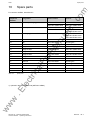
Stromaufnahme der DC 24V Versorgung:
Baugruppe
Die Werte sind zusätzlich zu den vom Grundgerät
verbrauchten 1 A notwendig.
CB1
190
CBP
150
CB2
100
CBC
100
T300 ohne Tacho
620
SCB1
50
SCB2
550
Stromaufnahme der Optionsbaugruppen
an
Stromversorgung
150
ua
ls
Tabelle 9.5
9.3
om
T100
.c
(Bei Bauform B erhöht sich durch den benötigten
Lüfter der Eigenbedarf des Grundgerätes von 0,5A
auf 1A).
Strombedarf (mA)
DC 24V Versorgung
9.4
Stromistwererfassung
Z = K91
ar
tM
Als Stromversorgung für die Einspeiseeinheit (Stecker X9) wird eine SITOP-Stromversorgung nach Katalog
KT10 empfohlen.
Bestell-Nr. des Nachrüstsatzes: 6SE7090-0XC85-1TD0
Brücke
IBemessung Ausgang
Bauform
J14
[A]
[Ω]
605
33,222
J11
ca
E
420
47,886
J10
375
53,647
J9
354
56,849
J8
270
74,557
J7
235
85,677
J6
222
90,720
J5
173
116,421
J4
142
141,887
J3
94
214,464
J2
86
234,523
J1
72
280,230
keine
41
492,381
J13
536
37,507
463
43,432
.E
lec
tri
J12
ww
w
B und C
Tabelle 9.6
9-4
Ri gesamt
lP
Geräte
Brücken der Stromistwerterfassung
DEUTSCH
Siemens AG 6SE7087-6AC85-0AA0
Einspeise-Einheit Betriebsanleitung
11.98
Optionen
Die Bürdenspannung bei Ausgangs-Bemessungsstrom beträgt 10V.
om
Übersetzungsverhältnis der Stromwandler 2000 : 1
Der Quellwiderstand Ri gesamt laut Tabelle.
HINWEIS
.c
Bei Anschluß von Meßgeräten wird je nach Innenwiderstand des Meßgerätes der effektive Bürdenwiderstand
und damit die Spannung verändert.
ua
ls
Für den kleinsten Ausgangs-Bemessungsstrom von 41A sind alle Brücken (J1 bis J14) offen. Für den größten
Ausgangs-Bemessungsstrom der Geräte-Bauformen B und C von 94A sind die Brücken J1 bis J3 geschlossen
und J4 bis J14 offen.
Beispiel: Für ein Gerät mit einem Ausgangs-Bemessungsstrom von 86A ist die Brücke J3 zu öffnen.
Im Auslieferzustand sind die Brücken (J1 bis J3) auf der Baugruppe 6SE7028-8FC85-0OA0 geschlossen. Vor
Inbetriebnahme sind daher die Brüchenstellungen nach Ausgangs-Bemessungsstrom (siehe Typenschild) und
Tabelle 9.6 vorzunehmen.
an
Netz
k
ca
l
X47
2
- I_IST
6SE7028-8FC85-0OA0
1
T2
X50
K
lP
T1
C98043-A1697-L1
+ I_IST
k
l
s
K
ar
tM
Die Durchsteckrichtung muß bei beiden Stromwandlern gleichsinnig sein!
J1 J2 J3 J4 J5 J6 J7 J8 J9 J10 J11 J12 J13 J14 J15 J16 J17
lec
tri
Brücke geschlossen
Brücke offen
X1:U1/L1 V1/L2 W1/L3
.E
Maßbild:
ww
Siemens AG 6SE7087-6AC85-0AA0
Einspeise-Einheit Betriebsanleitung
21,5
w
65
für M4
220
230
DEUTSCH
9-5
Optionen
Mechanik
om
9.5
11.98
Kurzbezeichnung Beschreibung
der Option
Nachrüstsatz
Bestell-Nr.
Z = M08
nur werksseitiger Einbau möglich
.c
mechanische Optionen
ww
w
.E
lec
tri
ca
lP
ar
tM
an
ua
ls
Tabelle 9.7
Doppelseitig lackierte Baugruppen
9-6
DEUTSCH
Siemens AG 6SE7087-6AC85-0AA0
Einspeise-Einheit Betriebsanleitung
02.96
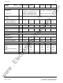
Ersatzteile
Für Einspeise-Einheiten Bauform B und C
om
10
Ersatzteile
Bezeichnung
Bestellnummer
Eingesetzt in
-A23
FBG-Wiederstandsvorladung
6SE7024-1EB85-0FA0
6SE7024-1EB85-0AA0
6SE7024-1FB85-0FA0
6SE7024-1FB85-0AA0
6SE7028-6EC85-0CA0
6SE7028-6EC85-0AA0
6SE7028-8FC85-0CA0
6SE7027-2FC85-0AA0
6SE7028-8FC85-0AA0
6SE7024-1FB85-0AA0
6SE7027-2FC85-0AA0
6SE7028-8FC85-0AA0
FBG-Steuerung
ua
ls
-A23
.c
Betriebsmittelkennzeichen
FBG-Vorladung PCU0
6SE7024-7FD84-1HH0
-E1
Lüfter
6SY7000-0AA48
allen Gerätetypen 1)
-V1
Brückengleichrichter
6SY7010-1AA01
6SE7024-1EB85-0AA0
-V1
Brückengleichrichter
-V1
Brückengleichrichter
-V1
Brückengleichrichter
-V1
Brückengleichrichter
-F1
Schmelzeinsatz
-F2
Schmelzeinsatz
-R100
Heißleiter
ar
tM
lP
ca
Ersatzteile
6SY7010-1AA02
6SE7024-1FB85-0AA0
6SY7010-1AA03
6SE7028-6EC85-0AA0
6SY7010-1AA04
6SE7027-2FC85-0AA0
6SY7010-1AA05
6SE7028-8FC85-0AA0
6SY7010-2AA01
allen Gerätetypen
6SY7010-2AA02
allen Gerätetypen
6SY7010-6AA01
allen Gerätetypen
lec
tri
Tabelle 10.1
an
-A24
ww
w
.E
1) bei 36A Geräten (6SE7024-1xB85) optional
Siemens AG 6SE7087-6AC85-0AA0
Einspeise-Einheit Betriebsanleitung
DEUTSCH
10-1
02.96
ww
w
.E
lec
tri
ca
lP
ar
tM
an
ua
ls
.c
om
Ersatzteile
10-2
DEUTSCH
Siemens AG 6SE7087-6AC85-0AA0
Einspeise-Einheit Betriebsanleitung
02.96
Umweltverträglichkeit
om
13
Umweltverträglichkeit
Umweltaspekte bei der Entwicklung
.c
Die Anzahl der Teile wurde durch Verwendung hochintegrierter Komponenten und durch modularen Aufbau der
gesamten Umrichterreihe stark reduziert. Dadurch sinkt der Energieverbrauch bei der Produktion.
ABS:
Frontabdeckung
Lüftergitter
PP:
Scharnier
Isolierplatte
Griffmulde
Busnachrüstung
PA6:
Isolierfolien
Klemmengehäuse
an
Eingesetzte Kunststoffteile:
ua
ls
Besonderes Augenmerk wurde auf die Reduzierung des Volumens, der Masse und der Typenvielfalt der Metallund Kunststoffteile gelegt.
ar
tM
Halogenhaltige Flammenschutzhemmer und silikonhaltige Isoliermaterialien wurden bei allen wesentlichen
Teilen durch schadstoffreie Materialien ersetzt.
Bei der Auswahl der Zulieferteile war Umweltverträglichkeit ein wichtiges Kriterium.
Umweltaspekte bei der Fertigung
lP
Der Transport der Zulieferteile geschieht vorwiegend in Umlaufverpackung. Das Verpackungsmaterial selbst ist
wiederverwertbar, es besteht hauptsächlich aus Kartonagen.
Auf Oberflächenbeschichtungen wird, bis auf Ausnahme des feuerverzinkten Seitenblechs, verzichtet.
ca
Die Produktion ist emissionsfrei.
lec
tri
Umweltaspekte bei der Entsorgung
Das Gerät kann über einfach lösbare Schraub- und Schnappverbindungen in recycelbare mechanische
Komponenten zerlegt werden.
Die Flachbaugruppen können der thermischen Verwertung zugeführt werden. Der Anteil an gefahrstoffhaltigen
Bauelementen ist geringfügig.
ww
w
.E
Die Kunststoffteile sind nach DIN 54840 gekennzeichnet und mit dem Recyclingsymbol versehen.
Siemens AG 6SE7087-6AC85-0AA0
Einspeise-Einheit Betriebsanleitung
DEUTSCH
13-1
02.96
ww
w
.E
lec
tri
ca
lP
ar
tM
an
ua
ls
.c
om
Umweltverträglichkeit
13-2
DEUTSCH
Siemens AG 6SE7087-6AC85-0AA0
Einspeise-Einheit Betriebsanleitung
11.98
Technische Daten
Technische Daten
om
14
Bei anderen als in diesem Kapitel aufgeführten Einsatzbedingungen, nehmen Sie bitte Kontakt mit Ihrer zuständigen Siemens-Niederlassung bzw. Landesgesellschaft auf.
Kühlmitteltemperatur
Lagerungstemperatur
− 25 °C bis +70 °C
Transporttemperatur
− 25 °C bis +70 °C
.c
0 °C bis +40 °C
3K3
DIN IEC 60721-3-3 / 04.90
Verschmutzungsgrad
2
DIN VDE 0110 Teil 1 / 01.89
Betauung nicht zulässig
Überspannungskategorie (Leistungsteil)
III
DIN VDE 0110 Teil 2 / 01.89
Überspannungsfestigkeitsklasse
(bei angeschlossenem Wechelrichter)
Schutzart
− Standard
1
E DIN VDE 0160 / 04.91
IP20
DIN VDE 0470 Teil1 / 11.92 =
^ EN 60529
an
Störfestigkeit
ua
ls
Umweltklasse
IEC 60801-2, IEC 60801-4
Mechanische Festigkeit
DIN IEC 60068-2-6 / 06.90
Konstante Amplitude der
Auslenkung
Beschleunigung
mm
m/s2 (g)
ar
tM
Frequenzbereich
Hz
10 bis 58
− beim stationären Einsatz
0,075
über 58 bis 500
9,8 (1)
3,5
9,8 (1)
lP
− beim Transport
ca
Die Geräte können auch in Belastungsklasse II betrieben werden. Die zulässigen Werte müssen den folgenden
Tabellen entnommen werden.
I
(A)
lec
tri
Belastungsklasse ΙΙ
136%
.E
100%
91%
60s
240s
t/(s)
Leistung nach Belastungsklasse II
ww
w
Bild 14.1
Belastungsklasse Ι
Siemens AG 6SE7087-6AC85-0AA0
Einspeise-Einheit Betriebsanleitung
DEUTSCH
14-1
Technische Daten
11.98
6SE70..-.....-0AA0 24-1EB85 28-6EC85
24-1FB85 27-2FC85 28-8FC85
Bemessungsspannung, Bemessungsfrequenz, Bemessungsstrom, Bemessungsleistung
V
3 AC 200V –10% bis 230V +15%,
bzw. 380V –15% bis 480V +10%
DC 270V –10% bis 310V +15%
bzw. 510V –15% bis 650V +10%
Bemessungsfrequenz fn
Eingang
Ausgang
Hz
Bemessungsstrom In
Eingang (Effektivwert) AC
Ausgang (Mittelwert) DC
A
36
41
74
86
37
78
36
41
62
72
82
94
A
37
66
86
Grundlastdauer
s
Überstrom Ausgang
Mittelwert
A
56
98
128
Überstromdauer
s
0,26
0,12
0,22
0,28
0,028
0,022 2)
0,028
0,028
240
56
117
60
Verluste, Kühlung, Leistungsfaktor
ar
tM
Bemessungsstrom Ausgang
Mittelwert
1
Leistungsfaktor
Netz cosϕ1N
kW
0,12
Kühlluftbedarf
m3/s
0,022 1)
Schalldruckpegel, Maße, Gewichte
60
60 2)
60
60
B
135
425
C
180
600
B
135
425
C
180
600
C
180
600
350
350
350
350
350
18
12
18
18
ca
mm
mm
60 1)
lec
tri
mm
kg
12
ww
w
.E
Gewicht ca.
dB(A)
lP
Verlustleistung
− Maximum
Bauform
Breite
Höhe
(ohne Befestigungslasche)
Tiefe
ua
ls
46 bis 64
D.C.
Belastungsklasse II nach EN 60146-1-1
Schalldruckpegel Lüfter
DC 675V –15% bis 810V +10%
.c
Ausgang Udn
3 AC 500V –10% bis 600V +10%
an
Bemessungsspannung
Eingang Un
om
E-Einheit
1 ) optional mit Zusatzstromversorgung
14-2
DEUTSCH
Siemens AG 6SE7087-6AC85-0AA0
Einspeise-Einheit Betriebsanleitung
11.98
Technische Daten
Leistungsreduzierung bei erhöhter Kühlmitteltemperatur
om
14.1
Bei Kühlmitteltemperaturen über 40°C muß der Bemessungsstrom bemäß Bild 14.2 reduziert werden.
Kühlmitteltemperaturen > 50°C sind nicht zulässig.
.c
zulässiger Bemessungsstrom
in %
100
ua
ls
90
80
75
60
Kühlmitteltemperatur in °C
10
30
40
50
Maximal zulässiger Bemessungsstrom in Abhänigkeit von der Kühlmitteltemperatur
ar
tM
Bild 14.2
20
an
70
14.2
Leistungsreduzierung bei Aufstellungshöhen > 1000m über NN
lec
tri
100
ca
zulässiger Bemessungsstrom
in %
lP
Bei Aufstellungshöhen > 1000 m über NN muß der Bemessungsstrom gemäß Bild 14.3 reduziert werden.
Aufstellungshöhen > 2000 m über NN auf Anfrage.
90
80
70
.E
60
1000
2000
3000
4000
Aufstellungshöhe
in m über NN
100
90
80
70
60
0
1000
2000
3000
4000
Aufstellungshöhe
in m über NN
w
0
zulässige Bemessungsspannung
in %
Maximalwerte für Bemessungsstrom und Bemessungsspannung in Abhänigkeit von der Aufstellungshöhe
ww
Bild 14.3
Siemens AG 6SE7087-6AC85-0AA0
Einspeise-Einheit Betriebsanleitung
DEUTSCH
14-3
Technische Daten
Errichten von Starkstromanlagen mit Nennspannungen bis 1000 V,
Auswahl und Errichtung elektrischer Betriebsmittel, Erdung, Schutzleiter,
Potentialausgleichleiter
Teil 1 A05.82
Teil 100
A03.83
Schutz gegen elektrischen Schlag:
Klassifizierung von elektrischen und elektronischen Betriebsmitteln (IEC 536)
Anordnung von Betätigungselementen in der Nähe berührungsgefährlicher
Teile
Teil 1 u. 2
A01.89
Isolationskoordination für elektrische Betriebsmitteln in
Niederspannungsanlagen
Teil 1 A06.93
Sicherheit von Maschinen: Elektrische Ausrüstung von Maschinen,
Allgemeine Anforderungen (EN 60204-1:1992)
E12.90 A05.88
Ausrüstung von Starkstromanlagen mit elektronischen Betriebsmitteln
DIN VDE 0106
DIN VDE 0110
VDE 0113
DIN VDE 0160
DIN VDE 0298
Teil 2 A11.79
Teil 4 A02.88
.c
Teil 540
A11.91
ua
ls
DIN VDE 0100
om
Angewandte Normen
Verwendung von Kabeln und isolierten Leitungen für Starkstromanlagen:
Empfohlene Werte für die Strombelastbarkeit von Kabeln mit Nennspannungen U0 / U bis 18/30 kV
Empfohlene Werte für die Strombelastbarkeit von Leitungen
an
14.3
11.98
Teil 1 A12.92
Schutzarten; Berührungs-, Fremdkörper- und Wasserschutz für elektrische
Betriebsmittel (EN 60529: 1991)
DIN VDE 0558
Teil1 A07.87
Halbleiter-Stromrichter: Allg. Bestimmungen und besondere Bestimmungen
für netzgeführte Stromrichter
DIN VDE 0843
Elektromagnetische Verträglichkeit von Meß-, Steuer- und
Regeleinrichtungen in der industriellen Prozeßtechnik:
Teil 2 A09.87 Z Störfestigkeit gegen Entladung statischer Elektrizität; Anforderungen und
Meßverfahren (IEC801-2) Ersetzt durch DIN EN 60801, Teil 2 (09.87)
Funkentstörung von elektrischen Betriebsmitteln und Anlagen:
Teil 1 A12.88 Z (EN 55014: 1987) Ersetzt durch DIN VDE 0875, Teil 14 und DIN VDE 0075
Teil 11 A07.92 (EN 55011: 1991)
DIN 41651
lP
Teil 5 A9.80
ca
DIN 41494
Bauweise für elektronische Einrichtungen; Baugruppenträger und
Baugruppen
lec
tri
DIN VDE 0875
ar
tM
DIN VDE 0470
Teil 1 A9.89
Steckverbinder für gedruckte Schaltungen zum Anschluß von Flachleitungen
mit runden Leitern; Indirektes Stecken, Rastermaß 2,54 mm
Elektrotechnik; Grundlegende Umweltprüfverfahren; Prüfungen
DIN IEC 60721
Teil 3 A08.87
Elektrotechnik; Klassifizierung von Umweltbedingungen:
Klassen von Einflußgrößen
Teil 4
Elektromagnetic compatibility for industrial - process mesurement and control
equipment
Electrical fast transient / burst requirements
.E
DIN IEC 60068 Teil 2
IEC 60801
1993
Teil 1-1
Halbleiter-Stromrichter;
Allgemeine Anforderungen und netzgeführte Stromrichter:
Festlegung der Grundanforderungen (IEC146-1-1991)
ww
w
EN 60146-1-1:
14-4
DEUTSCH
Siemens AG 6SE7087-6AC85-0AA0
Einspeise-Einheit Betriebsanleitung
11.98
Technische Daten
DIN VDE-Bestimmungen:
VDE-Auslieferungsstelle
Merianstraße 29
63069 Offenbach
.c
Beuth-Verlag GmbH
Burggrafenstraße 6
10787 Berlin
ww
w
.E
lec
tri
ca
lP
ar
tM
an
ua
ls
DIN-Normen und ausländische Normen:
om
Bezugsquellen:
Siemens AG 6SE7087-6AC85-0AA0
Einspeise-Einheit Betriebsanleitung
DEUTSCH
14-5
11.98
ww
w
.E
lec
tri
ca
lP
ar
tM
an
ua
ls
.c
om
Technische Daten
14-6
DEUTSCH
Siemens AG 6SE7087-6AC85-0AA0
Einspeise-Einheit Betriebsanleitung
ua
ls
Betriebsanleitung
Operating Instructions
ww
w
.E
lec
tri
ca
lP
ar
tM
an
SIMOVERT Master Drives
Einspeise-Einheit
Bauform B und C
Common Rectifier
Size B and C
.c
om
s
Ausgabe / Edition: E
Bestell-Nr. / Order-No.: 6SE7087-6AC85-0AA0
11.98
om
Allgemeines / General
Von dieser Betriebsanleitung sind folgende fremdsprachige Ausgaben lieferbar:
These Operating Instructions are available in the following languages:
Französisch
French
Spanisch
Spanish
Italienisch
Italian
Bestell-Nr.
Order-No.
6SE7087-7AC85-0AA0
6SE7087-8AC85-0AA0
6SE7087-2AC85-0AA0
ca
lP
ar
tM
an
ua
ls
.c
Sprache
Language
lec
tri
Weitergabe sowie Vervielfältigung dieser Unterlage, Verwertung und
Mitteilung ihres Inhalts nicht gestattet, soweit nicht ausdrüchlich
zugestanden. Zuwiderhandlungen verpflichten zu Schadenersatz. Alle
Rechte vorbehalten, insbesondere für den Fall der Patenterteilung oder
GM-Eintragung.
SIMOVERT ® ist ein Warenzeichen von Siemens
.E
Wir haben den Inhalt der Druckschrift auf Übereinstimmung mit der
beschriebenen Hard- und Software überprüft. Dennoch können
Abweichungen nicht ausgeschlossen werden, so daß wir für die
vollständige Übereinstimmung keine Garantie übernehmen. Die Angaben
in dieser Druckschrift werden jedoch regelmäßig überprüft und
notwendige Korrekturen sind in den nachfolgenden Auflagen enthalten.
Für Verbesserungsvorschläge sind wir dankbar.
The reproduction, transmission or use of this document or its contents is
not permitted without express written authority. Offenders will be liable for
damages. All rights, including rights created by patent grant or registration
of a utility model or design, are reserved.
ww
w
We have checked the contents of this document for conformity with the
hardware and software described. However, this does not absolutely
preclude deviations, and we therefore cannot guarantee complete
conformity. The information in the document is subjected to regular
scrutiny. Any necessary corrections will be made in subsequent editions.
We also welcome any suggestions you may have in the way of
improvement.
© Siemens AG 1998 All rights reserved
SIMOVERT ® Registered Trade Mark
11.98
Contents
om
ENGLISH
Definitions ................................................................................................................... 0-5
1
Description ................................................................................................................. 1-1
1.1
Applicability ...................................................................................................................... 1-1
1.2
Principle of operation ....................................................................................................... 1-1
2
Transport, unpacking, assembly ....................................................................... 2-1
2.1
Transport, unpacking ....................................................................................................... 2-1
2.2
Storage............................................................................................................................. 2-1
2.3
Assembly.......................................................................................................................... 2-2
2.4
Dimension drawings......................................................................................................... 2-3
3
Connection ................................................................................................................. 3-1
3.1
Power connections........................................................................................................... 3-2
3.2
Power supply / control...................................................................................................... 3-4
3.2.1
Electronic power supply / fault signal............................................................................... 3-4
3.2.2
Signalling relay X36 ('Warning' signal)............................................................................. 3-5
3.2.3
Settings on the module A23 ............................................................................................. 3-5
3.3
Control terminal strip of options ....................................................................................... 3-5
3.4
Measures for keeping to RFI suppression regulations .................................................... 3-7
3.5
Single-line diagrams with suggested circuit arrangements.............................................. 3-8
3.6
Power sections................................................................................................................. 3-10
4
ua
ls
an
ar
tM
lP
ca
Start-up ......................................................................................................................... 4-1
5
Blank
Blank
.E
6
7
.c
0
lec
tri
Contents
Malfunctions and warnings ................................................................................. 7-1
Fault signals ..................................................................................................................... 7-1
7.2
Warning signals................................................................................................................ 7-1
ww
w
7.1
Siemens AG 6SE7087-6AC85-0AA0
Common Rectifier Operating instructions
ENGLISH
0-3
Contents
11.98
Maintenance ............................................................................................................... 8-1
8-1
Maintenance recommendations ....................................................................................... 8-1
8.2
Replacing components..................................................................................................... 8-2
8.2.1
Replacing the fan ............................................................................................................. 8-2
8.2.2
Replacing modules........................................................................................................... 8-2
8.2.3
Replacing bridge rectifiers V1 .......................................................................................... 8-3
9
Options ......................................................................................................................... 9-1
9-1
A50 additional power supply PSR for optional modules .................................................. 9-1
9.2
Options which can be integrated into the electronics box................................................ 9-2
9.3
Power supply.................................................................................................................... 9-3
9.4
Actual-current sensing module......................................................................................... 9-3
9.5
Mechanical components .................................................................................................. 9-4
10
Spare parts .................................................................................................................. 10-1
11
Blank
12
Blank
13
Environmental compatibility ............................................................................... 13-1
14
Technical data ........................................................................................................... 14-1
14-1
Power reduction at increased coolant temperature ......................................................... 14-3
14.2
Power reduction at altitudes > 1000m above MSL .......................................................... 14-3
14.3
Applied standards............................................................................................................. 14-4
15
Index .............................................................................................................................. 15-1
ww
w
.E
lec
tri
ca
lP
ar
tM
an
ua
ls
.c
om
8
0-4
ENGLISH
Siemens AG 6SE7087-6AC85-0AA0
Common Rectifier Operating instructions
10.94
Definitions
om
0
Definitions
• QUALIFIED PERSONNEL
.c
within the meaning of these operating instructions or the warning information on the product itself, are
persons who are entrusted with installation, assembly, commissioning and operation of the product and who
avail of qualifications corresponding to their activities, e.g.:
1. training or instruction or authorisation to activate and deactivate, to earth and to mark circuits and
equipment in accordance with the standards of safety engineering.
ua
ls
2. training or instruction in accordance with the standards of safety engineering in the care and use of
suitable safety equipment.
3. training in First Aid
• DANGER
within the meaning of these operating instructions or the warning information on the product itself, indicates
that death and/or substantial property damage will result if proper precautions are not taken.
an
• WARNING
ar
tM
within the meaning of these operating instructions or the warning information on the product itself, indicates
that severe personal injury and/or substantial property damage will result if proper precautions are not taken.
• CAUTION
within the meaning of these operating instructions or the warning information on the product itself, indicates
that slight personal injury or property damage will result if proper precautions are not taken.
• NOTE
lec
tri
ca
lP
within the meaning of these operating instructions indicates important information about the product or the
respective part of the operating instructions to which attention is drawn.
NOTE
.E
For reasons of clarity, these operating instructions do not contain all details of all types of the product and can
also not take into account every conceivable installation, operation or maintenance circumstances.
You can consult your local Siemens branch if you should require further information or if particular problem
occur that are not dealt with in adequate detail in the operating instructions.
ww
w
Attention is also drawn to the fact that the contents of this instruction manual shall not become part of or
modify any prior or existing agreement, commitment or legal relationship. The sales contract, which also
contains the complete and solely valid warranty stipulations, contains the entire obligations of Siemens.
These contractual warranty stipulations are neither extended nor limited by the statements given in
instructions and documentation.
Siemens AG 6SE7087-6AC85-0AA0
Common Rectifier Operating instructions
ENGLISH
0-5
Definitions
10.94
om
CAUTION
Electrostatically Sensitive Devices (ESDs)
.c
The equipment contains electrostatically sensitive devices. These components may be destroyed very easily
by improper handling. Please observe the following notes if you nevertheless have to work with electronic
modules:
♦ Electronic modules should only be touched if absolutely necessary to carry out work on them.
ua
ls
♦ If modules nevertheless have to be touched, you must discharge your own body directly beforehand (this is
best done by touching an earthed conductive object such as the PE contact of a socket).
♦ Modules must not come into contact with highly insulating materials − e.g. plastic films, insulating desktops
or synthetic fibre clothing items.
♦ Modules must only be placed on conductive surfaces.
♦ When soldering modules, the tip of the soldering iron must be earthed.
an
♦ Modules and components must only be stored or dispatched in conductive packaging (e.g. metallised
plastic boxes or metal tins).
ar
tM
♦ If packagings are not conductive, modules must be placed in a conductive envelopment prior to packaging.
In this case, use can be made of conductive foam rubber or domestic aluminium foil, for example.
The necessary protective measures for ESDs are elucidated once again in the following figure:
conductive floor
ESD desk
ESD shoes
d
e
f
e
f
f
lec
tri
f
a
ESD coat
ESD armband
earthing terminal on cabinets
d
d
b
=
=
=
lP
=
=
=
ca
a
b
c
a
Standing position
e
f
f
c
a
Standing / Sitting position
ww
w
.E
Sitting position
c
d
b
0-6
ENGLISH
Siemens AG 6SE7087-6AC85-0AA0
Common Rectifier Operating instructions
Definitions
WARNING
om
10.94
When operating electrical equipment, certain parts of such equipment are inevitably live.
.c
Owing to the dc link capacitors, hazardous voltages are present on the equipment up to 5
min. after deenergisation (power terminal and electronic power supply). This is why it is
not permitted to open the housing until after waiting for 5 minutes.
Non-observance of warning notices can result in death, severe personal injury or
considerable property damage.
ua
ls
Only qualified personnel should work on or around the equipment after first becoming
thoroughly familiar with all warnings and maintenance procedures contained in these
Instructions.
ww
w
.E
lec
tri
ca
lP
ar
tM
an
Perfect and safe operation of the equipment requires proper transport, expert storage,
installation and assembly and cautious operation and maintenance.
Siemens AG 6SE7087-6AC85-0AA0
Common Rectifier Operating instructions
ENGLISH
0-7
10.94
ww
w
.E
lec
tri
ca
lP
ar
tM
an
ua
ls
.c
om
Definitions
0-8
ENGLISH
Siemens AG 6SE7087-6AC85-0AA0
Common Rectifier Operating instructions
Description
1
Description
1.1
Applicability
om
11.98
.c
The common rectifier in the SIMOVERT Master Drives series is a power electronics device. From the threephase mains, it generates a dc network and is used as a dc supply unit for one or several units in the
SIMOVERT Master Drives inverter series with a dc link.
ua
ls
A three-phase mains is connected to the input. One or more inverters and a brake chopper can be connected to
the DC output. The total of the rated currents of the installed inverters may then exceed the rated current of the
common rectifier. It must however be ensured in the course of system planning that at no moment in time is the
total of DC load currents greater than the rated DC current of the common rectifier. Feedback to the mains is
not possible.
Refer to the technical data in Chapter 14 for details of voltage and current ranges.
Principle of operation
an
1.2
The common rectifier consists of a 6-pulse diode bridge for rectification of the dc network.
ar
tM
Precharging begins as from the point when the mains voltage is applied and is realised by resistors in the dc
branch. The precharging resistors are bypassed by relays when the dc link voltage exceeds a given power-on
threshold. Within the +10 and -15 % mains voltage tolerance, and if the rated ac-side voltage is chosen
correctly on selector switch S1 and S3 and if the maximum possible capacitive load is observed, precharging
takes place within one second. The maximum dc link capacitance of a group drive must not exceed that of a
single inverter whose rated current in the dc link corresponds to the rated current of the common rectifier.
lP
Tapping of load current during precharging must be avoided!
ca
Bypassing of the precharging resistors will be interrupted if the dc link voltage should drop below the off
threshold as the result of a mains power failure or extreme drops in the mains voltage. This prevents excess
currents as the result of charging of the dc link capacitors at too fast a rate when the mains voltage returns.
lec
tri
The common rectifier does not check for an earth fault at the output of a connected converter because the
precharging resistors adequately protect its freewheeling diodes against excess current.
Excess temperature of the power section, excess temperature of the precharging resistors, phase failure and
the electronic power supply are monitored. Monitoring triggers deactivation and a fault signal in the event of any
hazard. The output current is not monitored. Protection against excess currents must be ensured by suitable
dimensioning and operation of the connected inverters.
.E
Use of a main contactor or a similarly functioning facility controlled by the fault signalling relay is necessary to
ensure safe and reliable operation of the common rectifier.
Fault signals are acknowledged by deactivating the mains voltage or the electronic power supply.
The on and off thresholds for bypassing the precharging resistors are defined by the setting of selector switch
S1 or S3 on module A23 (see Commissioning).
ww
w
The power for the electronics is supplied externally via a 24 V DC input.
Siemens AG 6SE7087-6AC85-0AA0
Common Rectifier Operating instructions
ENGLISH
1-1
11.98
ww
w
.E
lec
tri
ca
lP
ar
tM
an
ua
ls
.c
om
Description
1-2
ENGLISH
Siemens AG 6SE7087-6AC85-0AA0
Common Rectifier Operating instructions
11.98
Transport, unpacking, assembly
Transport, unpacking, assembly
2.1
Transport, unpacking
om
2
.c
The units are packed at the manufacturing works in conformity with the order. A product packaging plate is
attached to the box.
Avoid extreme vibrations and hard impacts during transport, e.g. when lowering the unit.
ua
ls
Pay attention to the notes on the packaging relating to transport, storage and proper handling.
The converter can be installed after unpacking it and checking the consignment for completeness and
damage.
The packaging consists of cardboard and corrugated cardboard. It may be disposed of in accordance
with local cardboard disposal regulations.
Storage
ar
tM
2.2
an
You should notify your freight forwarder immediately if you discover any transportation damage.
ww
w
.E
lec
tri
ca
lP
The units must be stored in clean dry rooms. Temperatures between −25 °C (−13 °F) and + 70 °C (158 °F) are
permissible. Temperature fluctuations > 20 K per hour are not permissible.
Siemens AG 6SE7087-6AC85-0AA0
Common Rectifier Operating instructions
ENGLISH
2-1
Transport, unpacking, assembly
Aids to assembly
om
2.3
11.98
.c
The following are required for securing:
♦ G rail conforming to EN50035 with screws for securing
♦ one M6 bolt
♦ dimension drawing (figure 2.2 for size B, figure 2.3 for size C).
WARNING
ua
ls
For safe operation of the unit, it is presumed it will be assembled and commissioned by
qualified personnel, paying attention to the warning notes given in these operating
instructions.
Particular note must be taken both of the general and national erection and safety
regulations regarding work on power installations (e.g. VDE) and regulations regarding the
proper use of tools and of personal protective equipment.
an
Non-observance of warning notices can result in death, severe personal injury or
considerable property damage.
Requirements for the installation site
ar
tM
The unit must be protected against the ingress of foreign matter as otherwise proper
functioning and safety will not be guaranteed.
Local guidelines and standards must be observed in relation to assembly.
Dissipated
power
lP
Operating facilities must be dry and dust-free. Air fed in must not contain
any gases, vapours or dusts that are electrically conductive or
detrimental to functioning. Air containing dust must be filtered.
WARNING
ca
Dimension cabinet ventilation according to the
dissipated power! (Technical data in Chapter 14)
lec
tri
The unit’s ambient climate in operating rooms must not exceed the
values of code 3K3 as detailed in DIN IEC 721 Part 3-3 /04.90. A
reduction of power as detailed in Chapters 14.1 and 14.2 is necessary in
the event of temperatures > 40 °C (104 °F) and altitudes >1000m. The
terminal voltage has to be reduced for altitudes > 2000m.
6SE70
Cooling air
≤ 40 °C (50°C)
Figure 2.1 Installation in control cabinets
ww
w
.E
Carry out assembly in accordance with the dimension drawings in
Chapter 2.4.
2-2
ENGLISH
Siemens AG 6SE7087-6AC85-0AA0
Common Rectifier Operating instructions
3)
4)
5)
40
50
w
100
425
100
1
2
X1
X37
S2
X36
R2
F2
F1
S3
S1
X1
X9
6)
X20
54321
X9
Top view
350
Air intake
V1
A23
Exhaust air 2)
Z
A23
2)
X36
S3
S1
20
35
23
41
4)
Detail Z
max. 5,7
1)
.c
Dimension: mm
Weight: approx. 12kg
om
No displacement of the centre of gravity
6) Connector for power supply DC24V
and fault signal
5) Shock-hazard protection
4) Screen connection for two cables.
3) Space required for cooling the unit.
2) Hook (suspension) for mounting on a
g-rail according to EN50035
1) Mounting hole for screw M6.
ua
ls
DANGER
WARNUNG
SIEMENS
SIEMENS
Front view
an
ar
tM
67,5
V1
D
135
X1
U1 V1 W1 PE C
47
Fiew without front cover
lP
ca
lec
tri
.E
125
6)
16
425
3)
225
ww
25
Siemens AG 6SE7087-6AC85-0AA0
Common Rectifier Operating instructions
R100
2.4
25
11.98
Transport, unpacking, assembly
Dimension drawings
Figure 2.2 Size B
ENGLISH
2-3
1)
DANGER
WARNUNG
SIEMENS
L1
90
X1
U1
X9
V1 W1 PE
C
D
L2
180
L3
L+
L-
Z
34
56
4)
2)
V1
R100
Exhaust air
S2
A23
5)
Air intake
DANGER
WARNUNG
350
X1
2
47
52
3)
3)
5) Connector for power supply DC24V
and fault signal
4) Screen connection for two cables.
3) Space required for cooling the unit.
2) Hook (suspension) for mounting on a
g-rail according to EN50035
1) Mounting hole for screw M6.
Detail Z
om
.c
max. 5,7
Dimension: mm
Weight: refer to section 14 (technical data)
No displacement of the centre of gravity
ua
ls
A24
1
R2
F2
F1
S3
S1
X37
X20 X36
X247
X9
5 4 3 2 1
126,7
an
ar
tM
lP
ca
lec
tri
.E
SIEMENS
82
69
16
600
View without front cover
54
23
43
X30.1
X30.2
ENGLISH
25
100
600
2-4
100
w
ww
Transport, unpacking, assembly
11.98
Figure 2.3 Size C
Siemens AG 6SE7087-6AC85-0AA0
Common Rectifier Operating instructions
11.98
WARNING
The units are operated with high voltages.
Only carry out connection work after disconnecting the voltage!
All work on the unit must only be carried out by qualified persons.
om
Connection
.c
3
Connection
Non-observance of warning notices can result in death, severe personal injury or
considerable property damage.
ua
ls
As the result of the dc link capacitors in the connected SIMOVERT Master Drives, the unit
still contains a hazardous voltage up to 5 min. after isolation. This is why it is only
permitted to open the unit after observing an appropriate waiting time.
The power terminals and control terminals may carry a voltage even when the motor is at
standstill.
When working on the open unit, pay attention to the fact that live parts are exposed.
ar
tM
an
The user is responsible for ensuring that the rectifier unit, converter, motor and other units
are installed and connected in accordance with the technical regulations recognised in the
country of installation (in Germany: VDE, VBG4) and other regionally valid regulations. In
doing so, particular attention must be paid to cable dimensioning, fusing, earthing,
deactivation, isolation and overcurrent protection.
NOTES
When the components used were being selected and when the clearance and creepage distances were being
determined, the regulations for safe isolation in accordance with VDE 0160 / prEN 50178 were complied with.
lP
It is the responsibility of the user to take these specifications into account when selecting an external power
supply.
ww
w
.E
lec
tri
ca
An external 24 V power supply is required in order to operate the unit (see Chapters 3.5 and 9.3).
Siemens AG 67087-6AC85-0AA0
Common Rectifier Operating instructions
ENGLISH
3-1
Connection
Power connections
om
3.1
11.98
WARNING
Incorrect connection to the mains will destroy the unit!
.c
The excitation coils of contactors and relays connected to the same mains network as the
unit, or which are located in its proximity, must be wired with surge arresters, e.g. RC
networks.
The unit must not be operated via a current-operated earth-leakage circuit-breaker (DIN
VDE 0160).
ua
ls
A voltage may only be applied to the unit after connecting SIMOVERT Master Drives.
Swapping or shorting the dc link terminals will destroy the SIMOVERT Master Drives
inverter!
an
The units are intended for permanent connection to the mains in conformity with DIN VDE 0160 Section 6.5.2.1.
PE conductor connection: minimum cross-section 10mm2.
ar
tM
The units must be fused on the mains side with semiconductor fuses as
detailed in Table 3.2. To avoid retroactive effects on the mains and to limit
harmonics, the mains should be connected via a 2 % commutation choke as
detailed in Table 3.3. Mains plus commutation activity must be ≥ 3% uk (ac
load carrying capacity of the dc link capacitors in the inverter). See Table 3.2
for details of order numbers for fuses.
Mains
dc link
W1
C
V1 L3
L+
L2
PE
D
U1
LL1
lP
The connection cross-sections given in Table 3.1 were determined for copper
cables at 40 °C (104 °F) ambient temperature. Data applies to multiple-wire
cables.
X1
The terminals accept the following range of cables:
Figure 3.1 Mains connection
ca
Type B: 2,5mm2 to 16mm2 / AWG 14 to AWG 6
lec
tri
Type C: 10mm2 to 50mm2 / AWG 8 to AWG 1/0
Unit order No.
Rated
input-
Conductor
U1/L1, V1/L2, W1/L3
Conductor
C/L+, D/L-
Conductor
PE
voltage
current
(V)
(A)
mm2
AWG 1)
mm2
AWG 1)
mm2
AWG 1)
24-1EB85-0AA0
200 to 480
36
16
6
16
6
16
6
28-6EC85-0AA0
200 to 480
74
50
1/0
50
1/0
25
4
24-1FB85-0AA0
500 to 600
36
16
6
16
6
16
6
27-2FC85-0AA0
500 to 600
62
35
2
35
2
16
6
28-8FC85-0AA0
500 to 600
82
50
1/0
50
1/0
25
4
.E
6SE70
Mains connection
ww
w
Table 3.1
1) American Wire Gauge
3-2
ENGLISH
Siemens AG 6SE7087-6AC85-0AA0
Common Rectifier Operating instructions
Connection
Column 1
Column 2
Column 3
Siemens gR
(SITOR)
Preferred type
Siemens (SITOR)
Bussmann
US-standard
A
Type
24-1EB85-0AA0
28-6EC85-0AA0
80
3NE1820-0
24-1FB85-0AA0
A
Type
A
Type
63
3NE4118
63
170M3610
125
3NE3222
125
170M3613
63
3NE4118
63
27-2FC85-0AA0
80
3NE1820-0
125
3NE3222
100
28-8FC85-0AA0
100
3NE1021-0
125
3NE3222
160
Column 1:
Recommended mains fuses
170M3690
170M3692
170M3693
This fuse with gR characteristic protects the semiconductors. At the same time, they also have
line protection characteristic which can be used if the appropriate conductor cross-sections are
chosen, e.g. in accordance with DIN VDE 0100 Part 430 (to be applied for preference).
an
Table 3.2
ua
ls
6SE70
Mains supply cable fuses
.c
Unit order No.
om
11.98
Unit order No.
Rated input-
Commutation choke 2 %
current
(V)
(A)
24-1EB85-0AA0
200 to 480
36
28-6EC85-0AA0
200 to 480
74
24-1FB85-0AA0
500 to 600
27-2FC85-0AA0
500 to 600
Rated current
(V / Hz)
(A)
400 / 50
460 / 60
35,5
4EP3900-2UK
400 / 50
460 / 60
80
36
4EP3700-1UK
500 / 50
35,5
62
4EP3900-1UK
500 / 50
63
500 / 50
80
4EP3700-2UK
ca
500 to 600
Voltage / Frequency
(V / Hz)
lec
tri
28-8FC85-0AA0
82
4EP4000-1UK
Recommended commutation choke
ww
w
.E
Table 3.3
Type
lP
voltage
6SE70
ar
tM
Column 2, 3: Semiconductor protection only, lines are not reliably protected. Discriminative line protection is
assured only by correlating the line protection fuses to the installed conductor cross-section in
accordance with the applicable regulations - e.g. DIN VDE 0100 Part 430.
Siemens AG 67087-6AC85-0AA0
Common Rectifier Operating instructions
ENGLISH
3-3
11.98
3.2
Power supply / control
3.2.1
Electronic power supply / fault signal
om
Connection
The electronic power supply is not included in the scope of supply of the common rectifier.
Function description
perm. conductor
cross-section
(mm2)
(AWG)
X9
1
2)
DC 24V (tolerance range 20V - 30V)
max. current consumption 2A at +24V
0,2 to 2,5
X9
Reference potential
0,2 to 2,5
24 to 14
3
not connected (N.C.)
0,2 to 2,5
24 to 14
4
Fault signal 2)
0,2 to 2,5
24 to 14
5
2)
0,2 to 2,5
24 to 14
an
2
M
Permissible connection cross-sections for the power supply and the fault signal
1
2
3
4
5
AC 230V
1500VA
Figure 3.2 DC 24 V power supply
and fault signal
connection
ar
tM
Table 3.3
Fault signal
24 to 14
P
max. current consumption without options:
size B = 0.5A, size C = 1A
Fault signal
ext. SV
DC 24V
ua
ls
Terminal
.c
Plug-in terminal X9
Terminal X9.1 fused with fuse T2A/250V träge/time-lag 5x20mm
(19198-T2A/250V Messrs. Wickmann-Werke GmbH respectively
0034.3993 FSD Messrs. Schurter)
lP
Terminal X9.2 fused with fuse T3,2A/250V träge/time-lag 5x20mm
(19198-T3,2A/250V Messrs. Wickmann-Werke GmbH respectively
0034.3998 FSD Messrs. Schurter)
WARNING
ca
For safety reasons, we recommend that a master contactor or other device with a similar
function is fitted on the mains system side which disconnects the unit from the mains
system when the "Fault" contact opens.
lec
tri
In cases where a main contactor is fitted, a latching circuit should be provided for this in
order to prevent unexpected reclosing after faults.
NOTES
The main contactor’s exciter coil must be wired with surge arresters, e.g. an RC network for AC or a diode for
DC.
.E
The 'Fault' relay contact (terminal X9) must be looped directly or indirectly into the main contactor control. Use
of a main contactor is necessary to protect the unit. Connection of a latching relay prevents unexpected
activation when the fault is remedied.
ww
w
In the event of phase failure, operation of the main contactor without latching leads to cyclic deactivation and
activation of the main contactor because the phase failure signal is suppressed in the event of a mains failure.
Mains failure on the unit arises by virtue of the fact that the main contactor drops out in the event of a
malfunction.
2) Contacts for switching the main contactor between terminals 4 and 5 ; switching voltage AC 230V max. AC 3A at cosϕ ≥ 0.4; max.
switching capacity 1500 VA ; at switching voltage DC 30V max. DC 5A
3-4
ENGLISH
Siemens AG 6SE7087-6AC85-0AA0
Common Rectifier Operating instructions
11.98
Connection
3.2.2
Signalling relay X36 ('Warning' signal)
om
Plug-in terminal X36
X36-1
X36-2
Signalling contacts to switch extra-low voltage between terminals
1 and 2 at a switching voltage of DC 30 V max.DC 5 A, at a
switching voltage of AC 60 V max. AC 5 A at cosϕ ≥ 0,4
Table 3.5
Warning
3.2.3
Settings on the module A23:
perm. conductor
cross-section
(mm2)
(AWG)
.c
Function description
0,2 to 2,5
24 to 14
ua
ls
Terminals
an
R2: 0 resistance as earth - reference potential M connection
On delivery, M is connected to earth. Remove this resistor only to avoid disturbances from earth loops, i.e. if the
electronic reference potential is otherwise connected to earth (e.g. via the reference potential connection
terminal of the power supply unit. The 0 resistor R210 on the A50 module must additionally be removed when
using the additional power suppy A50 (see Chapter 9.1).
ar
tM
S1: Set the rated supply voltage with S1 (Piano DIP switch) (press down the applicable lever). Only one voltage
must be selected.
The setting of the system mains voltage on the switch S1 must correspond exactly with the one set on the
connected converters, thus guaranteeing a correct bypassing sequence and load current extraction (see
Chapter 4, Table 4.1 or 4.2).
ca
lP
S2: The status of the bridging relays can be switched through to the "Warning" output (terminal X36) with S2
(DIP-Fix). When S2 is open, the "Warning" relay is opened only in the event of the excess temperature prewarning.
Control terminal strip of options
lec
tri
3.3
CAUTION
.E
The unit must be in the deenergised state in order to connect the control lines to X9, X36
and X37.
♦ A50 additional power supply PSR for optional modules
Connector X37
ww
w
Connector X37
Function description
Pin 1
DC 24V connected to terminal X9-1 via a 2A slow-blow fuse
Pin 2
Electronic reference potential connected to terminal X9-2 via a 3.2A slow-blow fuse
Table 3.6
Connection of additional power supply
Siemens AG 67087-6AC85-0AA0
Common Rectifier Operating instructions
ENGLISH
3-5
Connection
11.98
om
♦ Fan for additional power supply in the case of 36A units (6SE7024-1xB85)
(not a customer terminal)
Connector X20
Function description
Pin 1
DC 24V via a controlled voltage limiter
Pin 2
Reference potential
Fan connection
ua
ls
Table 3.7
.c
Connector X20
♦ Connecting control lines of optional modules (in preparation)
NOTE
an
When installed, control lines must be shielded and isolated from the power cables, laying them at a minimum
distance of 20 cm. The shield must be connected on both sides. On the unit's housing, the shield is connected
with shield clamps. Handling of these clamps is shown in Figure 3.3.
ar
tM
When they intersect, control and power cables must be laid at an angle of 90°.
Fitting the shielding clamp
Cable binder
Connector
∅ ≤ 7,5mm
∅ ≤ 5mm
lP
Slide on shield
and secure with
shrink-on tubing,
for example
∅ ≤ 15mm
ca
Adapt length
to design
lec
tri
Do not bend
spring over
35
Manually or using a screwdriver,
press the clamp together and extract
it in the updown direction.
Caution!
The clamps are sharp-edged!
.E
Shield
Releasing the shielding clamp
Figure 3.3 Connecting the control lines and handling the shielding clamps
w
Use must be made of the 'EMC shielding housing' option if so many control lines are needed that two shielding
clamps are not enough.
ww
Order numbers:
♦ Design B
6SE7090-0XB87-3CA0
♦ Design C
6SE7090-0XC87-3CA0
3-6
ENGLISH
Siemens AG 6SE7087-6AC85-0AA0
Common Rectifier Operating instructions
11.98
Measures for keeping to RFI suppression regulations
om
3.4
Connection
The following points must be observed in order to comply with the radio-frequency interference suppression
requirements:
ua
ls
.c
• Grounding
Radio frequency interference results from operation of the converters. Such interference voltages should be
returned to the source by means of low-resistance connections (cross-section of the ground connection
cross-section of the power supply system connection).
On installation of the power supply unit and of any optional RFI filters use should be made of the best
available method of grounding (e.g. mounting plate, earthing wire, earthing bus). Connect all conductive
housings together so as to make contact over a large area.
Not only the cross-section (governed also by the safety regulations which should be observed to obviate the
effects of a fault) but also the contact surfaces are of vital importance for RFI suppression, since high
frequency interference currents do not flow through the entire cross-section but mainly on the outer surface
of the conductor.
• Shielding
The following measures are required in order to attenuate interference and to meet the RFI suppression
requirements
an
− use of shielded cable between the output of the converter and the motor and
− use of shielded control cables.
The shield must be connected to earth potential at both ends.
ar
tM
• Filters
The RFI suppression filters must be connected directly before the power supply unit. The housings must be
interconnected by means of an electrically conductive connection.
ww
w
.E
lec
tri
ca
lP
Type A1 RFI suppression filters are recommended for compliance with the RFI suppresssion requirements.
Siemens AG 67087-6AC85-0AA0
Common Rectifier Operating instructions
ENGLISH
3-7
3-8
ENGLISH
Off
1) Fan only when using the A50 (C98043-A1699)
Additional power supply PSR for optional modules
On
X36-2
X36-1
X9-5
X9-4
X9-3
X9-2
X9-1
X37-2
F1
A23
C98043-A1692
D/L-
+
-
GLR-
GLR+
X20-2
X20-1
X30-2
X30-1
W1/L3
V1/L2
U1/L1
ua
ls
an
M
+24V
X1: C/L+
Warning
Malfunction
N.C.
F2
Filter
(optional)
X1: U1 V1 W1 PE
L1 L2 L3
ar
tM
X37-1
K1
+
1)
om
Power section
E1
M
.c
ϑ
R100
-
V1
3.5
24V-power supply unit
lP
A50 (C98043-A1699)
Additional power supply PSR
for optional modules
ca
lec
tri
.E
3AC 50-60Hz, 400V
3AC 50-60Hz, 500V
1AC 50-60Hz, 230V
w
ww
Connection
11.98
Single-line diagrams with suggested circuit arrangements
Figure 3.4 Single-line diagram with suggested circuit arrangement, size B
Siemens AG 6SE7087-6AC85-0AA0
Common Rectifier Operating instructions
w
ww
Siemens AG 67087-6AC85-0AA0
Common Rectifier Operating instructions
On
Off
24V-power supply unit
X36-2
X36-1
X9-5
X9-4
X9-3
X9-2
X9-1
X37-2
X37-1
F1
+24V
M
A23
C98043-A1693
Warning
Malfunction
N.C.
F2
W1/L3
K1
+
-
X20-1
X30-2
X30-1
Filter
(optional)
X248-2
-
NUD
-
V1
X1: D/L-
om
.c
PUD
M
E1
A24
PCU0
ϑ
R100
X1: C/L+
X248-1
X247-2
+
+
X1: U1 V1 W1 PE
L1 L2 L3
X247-1
GLR+
X20-2
ua
ls
D/L-
V1/L2
C/L+
U1/L1
an
ar
tM
A50 (C98043-A1699)
Additional power supply PSR
for optional modules
lP
ca
lec
tri
.E
3AC 50-60Hz, 400V
3AC 50-60Hz, 500V
1AC 50-60Hz, 230V
11.98
Connection
Figure 3.5 Single-line diagram with suggested circuit arrangement, size C
ENGLISH
3-9
w
ww
A50 (C98043-A1699)
Additional power supply PSR
for optional modules
Warning
Malfunction
24V-power supply unit
X37-2
X37-1
X36-2
X36-1
X9-5
X9-4
X9-3
X9-2
X9-1
X30-1
X30-2
R100
J
F1
T2A
M
+
X20-1
X20-2
-
K501-2
K440-2
-
+
+
~
~
X1: U1/
L1
~
~
C2
V1/
L2
~
~
+
X1: C/L+
-
-
V1
K702-3
X1: D/L-
om
.c
W1/ PE
L3
ua
ls
an
ar
tM
lP
A23
C98043-A1692
N.C.
F2
T3,2A
ca
lec
tri
.E
Termal sensor
on the heatsink
K701-2
E1
R712 R715
ENGLISH
K701-3
3-10
R706 R709
3.6
K702-2
Fan only when using the A50 (C98043-A1699)
Additional power supply PSR for optional modules
Connection
11.98
Power sections
Figure 3.6 Power section, size B
Siemens AG 6SE7087-6AC85-0AA0
Common Rectifier Operating instructions
w
ww
A50 (C98043-A1699)
Additional power supply PSR
for optional modules
Warning
Malfunction
24V-power supply unit
ϑ
X30-1
X30-2
R100
X37-2
X37-1
X36-2
X36-1
X9-5
X9-4
X9-3
X9-2
X9-1
F1
T2A
K501-2
K440-2
-
-
+
GLR+
U1/L1
V1/L2
W1/L3
C/L+
D/L-
X247-2
X247-1
X247-1
X248-2
X248-1
X247-2
X241
+
+
K4
ua
ls
an
ar
tM
lP
+
X20-1
X20-2
A23
C98043-A1693
N.C.
F2
T3,2A
ca
lec
tri
.E
Termal sensor
on the heatsink
X1: C/L+
PUD
X242
K2
M
R423 R422 R421
C1
A24
PCU0
~
V1/
L2
~
W1/ PE
L3
R411 R412 R413
X243
-
-
V1
X244
X1: D/L-
NUD
om
.c
~
X1: U1/
L1
K1
Siemens AG 67087-6AC85-0AA0
Common Rectifier Operating instructions
K3
E1
11.98
Connection
Figure 3.7 Power section, size C
ENGLISH
3-11
11.98
ww
w
.E
lec
tri
ca
lP
ar
tM
an
ua
ls
.c
om
Connection
3-12
ENGLISH
Siemens AG 6SE7087-6AC85-0AA0
Common Rectifier Operating instructions
11.98
WARNING
The units 6SE70 are operated with high voltages.
All work on the unit must only be carried out by qualified persons.
om
Start-up
.c
4
Start-up
Non-observance of warning notices can result in death, severe personal injury or
considerable property damage.
ua
ls
Owing to the dc link capacitors, a hazardous voltage still prevails inside the unit for up to 5
min. after deactivation. This is why it is only permitted to open the unit after a
corresponding waiting period.
When working on the open unit, pay attention to the fact that live parts are exposed.
an
Even when the motor is at standstill, the following parts of the unit may be carrying a live
voltage:
- the mains connection terminals U1/L1, V1/L2 and W1/L3
- the output terminals C/L+ and D/L- the terminals of the control terminal strip
lP
ar
tM
The user is responsible for ensuring that the rectifier unit, converter, motor and other units
are installed and connected in accordance with the technical regulations recognised in the
country of installation (in Germany: VDE, VBG4) and other regionally valid regulations. In
doing so, particular attention must be paid to cable dimensioning, fusing, earthing,
deactivation, isolation and overcurrent protection.
NOTES
ca
If there are high capacitances (noise suppression capacitors) between the star point of the mains (earth) and
the dc link, and the dc link is unloaded, it may charge up by √2 more than is normally the case.
lec
tri
In the event of an earth fault at the converter output, the current through the freewheeling diodes of the
converters is adequately limited by the precharging resistors during the precharging process. The connected
converters automatically detect earth faults during operation of the inverter.
In the event of phase failure, operation of the main contactor without latching leads to cyclic deactivation and
activation of the main contactor because the phase failure signal is suppressed if a mains failure should occur.
The mains failure on the unit results from dropping out of the main contactor in the event of a fault.
ww
w
.E
The fan is only activated if the precharging resistors are shorted.
Siemens AG 6SE7087-6AC85-0AA0
Common Rectifier Operating instructions
ENGLISH
4-1
Start-up
11.98
om
WARNING
The rated ac-side voltage setting on the switch S1 must correspond exactly with the
voltage set on the connected converters, thus guaranteeing the correct sequence of
bypassing and load current extraction.
.c
If the rated ac-side voltage is set too high, the end of precharging is not reached when one
of the connected converter is tapping load current adequately. Consequently, the
precharging resistors get overheated and the unit switches off with a 'Fault' signal. The
bypassing relays also open too early in the event of mains voltage drops and may be
damaged by dc arcs.
ua
ls
If the rated ac-side voltage is set too low, the precharging resistors are bypassed too early
and an overcurrent pulse occurs which may lead to damaging of the rectifier, the relay
contacts and the fuses.
When using parallel converters, it is imperative to connect the positive and negative poles
(C/L+ and D/L-) of the dc link correctly because its freewheeling diodes are not adequately
protected against excess currents by the fuses of the common rectifier.
an
Operation without a main contactor or a similarly functioning device that isolates the unit
from the mains when the 'Fault' contact opens is not permissible and may lead to
damaging of the unit.
To prevent unexpected activation after malfunctions, it is necessary to wire a latching
circuit for the main contactor.
ar
tM
A voltage must be selected with switches S1 or S3 as otherwise the fuse will drop out.
Precharging begins as from the point when the mains voltage is applied and is ended by bridging of the
precharging resistors when Ud exceeds the On threshold.
lec
tri
460
Rated values of DC-link
voltage Und in V= at rated load
(set parameter P071 on the
SIMOVERT Master Drive)
605
ca
Rated voltage Un
chained in Vrms (A.C.)
lP
When Ud falls below the Off threshold, bridging of the precharging resistors is ended and the unit is again in the
precharging state.
On threshold
of Ud in V=
Off threshold
of Ud in V=
508
419
578
486
400
415
545
458
378
400
526
442
364
380
500
420
346
230
302
254
209
200
263
220
181
.E
440
On and off thresholds for units 6SE70xx-xEx8x
ww
w
Table 4.1
4-2
ENGLISH
Siemens AG 6SE7087-6AC85-0AA0
Common Rectifier Operating instructions
Start-up
L1
460
440
415
400
380
230
663
546
575
756
635
525
690
580
500
657
552
On and off thresholds for units 6SE70xx-xFx8x
S1
L2
600
575
525
500
-----
S1
S3
1
2
3
4
5
6
S1
1 0
523
478
455
L1
460
440
415
400
380
230
L2
600
575
525
500
-----
S3
6
5
4
3
2
1
S1
0 1
Size C
Position on A23
Fig. 4.1 Selector switches S1 and S3 on the A23 board
ar
tM
Size B
.c
Off threshold
of Ud in V=
an
Table 4.2
On threshold
of Ud in V=
600
Nominal dc link voltage values
Und in V=
(set parameter P071 on the
SIMOVERT Master Drive)
789
ua
ls
Rated voltage Un
chained in Vrms (A.C.)
om
11.98
Position on A23
460 V position also for 480 V, S3 for 200 V
lP
The following commissioning steps must be carried out after connecting the unit
(as detailed in Chapter 3):
for 200-230V and 380-480V units = 400V
for 500-600V units = 500V
lec
tri
Works setting:
ca
♦ Set the rated mains voltage with S1 (Piano DIP switch) (press the corresponding lever of the switch towards
the module). It is only permissible to select one voltage (S3 also open).
The 200 V voltage range is activated by closing DIP-fix jumper S3 (by means of S1), whereby all the levers
of S1 must be open.
♦ The status of the bridging relays can be switched through to the "Warning" output (terminal X36) with the
jumper S2 (DIP-Fix). When S2 is open, the "Warning" relay is opened only in the event of the excess
temperature pre-warning.
Works setting:
S2 open
♦ Switch on the mains and electronic power supply.
ww
w
.E
♦ Enable the converter.
Siemens AG 6SE7087-6AC85-0AA0
Common Rectifier Operating instructions
ENGLISH
4-3
11.98
ww
w
.E
lec
tri
ca
lP
ar
tM
an
ua
ls
.c
om
Start-up
4-4
ENGLISH
Siemens AG 6SE7087-6AC85-0AA0
Common Rectifier Operating instructions
Malfunctions and warnings
7
Malfunctions and warnings
7.1
Fault signals
.c
The fault relay K440 at terminals X9-4 and X9-5 interrupts. The fault is not stored in the unit.
om
11.98
Remedy
Electronic power supply is less than DC 18 V
Check electronic power supply of 20 to 30 V;
check fuses F1 and F2.
No rated ac-side voltage selected on S1/S3
A lever on S1 must have been pressed towards
the p.c.b. board or dip-switch S3 must have been
closed.
Several rated ac-side voltages selected on S1
It is permissible for only one lever on S1 to be
pressed towards the p.c.b. board if dip-switch S3
is open. It is not permissible for a lever on S1 to be
pressed towards the p.c.b. board if dip-switch S3
has been closed.
Phase failure for more than 1 second
Check the mains.
Overloading of the precharging resistors by
excessive dc link capacitance or load current
tapping during precharging or too frequent
precharging in a short time
Correctly set the rated ac-side voltage on S1 and
adjust all connected converters properly; check
coordination of the build-up of the dc link voltage
and load current tapping as well as the sum of the
dc link capacitances.
Excess temperature of the power section
Switching threshold = 90°C ±5°C
Reduce current extraction; check the air
throughput (fan); check the ingoing air
temperature.
lP
ar
tM
an
ua
ls
Possible cause
ca
A fault signal is issued immediately via K440 if one of these faults occurs (the unit must then be isolated from all
3 phases of the mains). The unit does not store or indicate the fault.
It is advisable to wire the main contactor as described in the connection suggestion in Chapter 3.5.
7.2
lec
tri
The fault is registered by a fault acknowledgement on the latching circuit of the main contactor or a similarly
funcitoning facility. Precharging begins immediately again after the mains voltage has been applied.
Warning signals
Warning relay K501 at terminals X36-1 and X36-2 interrupts.
.E
Cause
Remedy
Reduce current extraction; check the air
throughput; check the ingoing air
temperature.
If the DIP-FIX switch S2 is closed, a warning is
also issued during precharging.
Open DIP-FIX switch S2.
ww
w
Excess temperature of the power section
prewarning
Switching threshold = 6°C below the fault signal
threshold (90°C ±5°C)
Siemens AG 6SE7087-6AC85-0AA0
Common Rectifier Operating instructions
ENGLISH
7-1
11.98
ww
w
.E
lec
tri
ca
lP
ar
tM
an
ua
ls
.c
om
Malfunctions and warnings
7-2
ENGLISH
Siemens AG 6SE7087-6AC85-0AA0
Common Rectifier Operating instructions
11.98
Maintenance
WARNING
The units SIMOVERT Master Drives are operated with high voltages.
om
8
Maintenance
.c
All work on the unit must be carried out in agreement with the national electrical regulations
(in Germany: VBG 4).
Maintenance and repair work must only be carried out by qualified personnel.
Use must only be made ofd spare parts approved by the manufacturer.
ua
ls
It is imperative to observe the prescribed maintenance intervals and the repair and
replacement instructions.
Owing to the dc link capacitors, hazardous voltages still prevail in the unit up to 5 min. after
deenergisation (power terminal and electronic power supply). This is why it is only
permitted to open the unit after a corresponding waiting time.
The power and control terminals may still be live even in the even of motor standstill.
ar
tM
an
If work on the activated unit is necessary:
♦ do not touch any live parts.
♦ use only proper measuring equipment and protective work clothing.
♦ stand or sit on an unearthed and isolated surface that does justice to ESD
requirements.
Non-observance of warning notices can result in death, severe personal injury or
considerable property damage.
Maintenance recommendations
ca
8.1
lP
You should know the order and factory numbers of your unit when consulting the service department. You will
find these numbers and other important data on the rating plate of the unit.
lec
tri
Dust deposits inside the unit must be removed at least once annually by qualified personnel. If required,
cleaning must take place at shorter intervals. The unit must be cleaned with a brush and vacuum cleaner and in
inaccessible locations with dust-free dry compressed air at a maximum of 1 bar.
ww
w
.E
The DC-24V fan is designed for an operating life of 35 000 hours at an ambient temperature of 40 °C. It must be
replaced in good time to maintain the availability of the unit.
Siemens AG 6SE7087-6AC85-0AA0
Common Rectifier Operating instructions
ENGLISH
8-1
11.98
8.2
Replacing components
8.2.1
Replacing the fan
om
Maintenance
WARNING
.c
The fan must only be replaced by qualified personnel.
ua
ls
Owing to the dc link capacitors, a hazardous voltage prevails for a further 5 min.
after deenergisation.
Non-observance of warning notices can result in death, severe personal injury
or considerable property damage.
Sizes B and C
The fan is located on the underside of the unit
X20
♦ Undo both M4 x 49 Torx screws
♦ Remove the protective grille
an
M4 x 49
Torx T20
♦ Pull the fan down and extract the connector
X20
ar
tM
♦ Install a new fan in reverse order
♦ Before commissioning the unit, check that the
fan does not rub and also check the air flow
direction (arrow pointing upward). The air
must be discharged from the unit in the
upward direction.
Protective grille
Fan E1
M4 x 49 / Torx T20
Replacing modules
ca
8.2.2
lP
Figure 8.1 Protective grille and fan (24 V) for sizes B and C
WARNING
lec
tri
Modules must only be replaced by qualified persons.
Modules must not be removed or inserted under a live voltage.
Non-observance of warning notices can result in death, severe personal injury
or considerable property damage.
CAUTION
ww
w
.E
The modules contain electrostatically sensitive devices. You must discharge your own
body before touching an electronic module. This is best done by touching a conductive
earthed object (e.g. a bare metal part of the control cabinet) directly beforehand.
8-2
ENGLISH
Siemens AG 6SE7087-6AC85-0AA0
Common Rectifier Operating instructions
11.98
Maintenance
♦ Undo the securing screws of the modules
above and below the insertion /removal aids
♦ By means of the insertion /removal aids,
carefully pull the module out of the
electronics box, making sure that the
module does not get stuck
om
Replacing modules in the electronics box
(option)
S lo t 1 (P S R )
S lo t 3 (o p tio n s )
ua
ls
♦ Carefully insert the new module in the guide
rails until it moves no further in the
electronics box
.c
S lo t 2 (o p tio n s )
ar
tM
an
♦ Firmly screw down the module with the
securing screws above and below the
insertion / removal aids.
Figure 8.2 Electronics box, equipped with PSR (slot 1)
Replacing bridge rectifiers V1
ca
8.2.3
lP
and options (slots 2 and 3)
ww
w
.E
lec
tri
The bridge rectifier is secured with self-tapping screws. When replacing the bridge rectifier, it is imperative to
use original-length screws with locking elements to secure it.
Also use original-length screws when screwing the bridge rectifier to the connecting cables.
Siemens AG 6SE7087-6AC85-0AA0
Common Rectifier Operating instructions
ENGLISH
8-3
11.98
ww
w
.E
lec
tri
ca
lP
ar
tM
an
ua
ls
.c
om
Maintenance
8-4
ENGLISH
Siemens AG 6SE7087-6AC85-0AA0
Common Rectifier Operating instructions
Options
9
Options
9.1
A50 additional power supply PSR for optional modules
Z = K90
.c
Spare part order no.: 6SE7090-0XX85-0KA0
om
11.98
ua
ls
The additional power supply A50 is connected to the module A23 by means of a 2-pole cable and inserted on
the left in slot 1. The module is secured on the electronics box by means of the screws of the extraction aid
(earth-reference potential connection: see Chapter 3.2.3).
CAUTION
an
The maximum total power that can be extracted is 19 W (taking into account the maximum
consumption of the common rectifier and common 2 A fuse for the DC 24 V power supply
on the module A23).
Designation
Voltage
Current
Overload protection
Tolerance
Current limiting
± 2%
0 to 0. 8A (0.65A 1) )
Current limiting
± 3%
-15 V
0 to 0. 33A (0.3A 1) )
Current limiting
± 3%
+24 V
0 to 0.2 A
NTC thermistor
Corresponds to the
DC 24V power supply
+5 V
0 to 3.5 A
P15
+15 V
N15
P24_AUX
lP
P5
Output voltages and possible currents of additional power supply
ca
Table 9.1
ar
tM
Output voltages and possible currents at the corresponding pins of connector X107
lec
tri
Input
Plug-in terminal X37 on A50 (corresponds to the output plug connector X37 on A23):
Terminal
1
2
DC 24V power supply tolerance: 20V - 30V (fused with 2 A slow-blow on module A23)
Reference potential (fused with 3.2 A slow-blow on module A23)
Connection of additional power supply
ww
w
.E
Table 9.2
Function description
1) maximum load current on switch-on
Siemens AG 6SE7087-6AC85-0AA0
Common Rectifier Operating instructions
ENGLISH
9-1
Options
11.98
Options which can be integrated into the electronics box
om
9.2
Local bus adapter (LBA) for fitting optional supplementary boards
The LBA option is a precondition for fitting optional supplementary boards. If there is no LBA in the unit yet, it
must be built into the electronics box before an option board can be slotted in.
.c
Mounting the local bus adapter LBA in the electronics box
♦ Use the handles to pull out the PSR board
after undoing the two fixing screws.
ua
ls
♦ Push the LBA into the electronics box (for
position, see illustration on the right) until it
clicks in.
an
♦ Re-insert the PSR board into the left-hand slot
and tighten the fixing screws in the handles.
ar
tM
Slot 2 (options)
Slot 3 (options)
Slot 1 (PSR)
In order to use the CBC and CBP boards, an ADB (adapter board) is needed in addition to the LBA. Due to their
smaller mechanical dimensions, these boards must be plugged onto an ADB so that they can be slotted into the
electronics box.
lP
The options are supplied with the option description.
Description
LBA
Local bus adapter for the electronics box. This is
required for installing T300, CB1, TSY, SCB1 and
SCB2
Board
description
ADB
Adapter board for small boards. Precondition for fitting
CBC and CBP
Board
T100
Technology board
Board
description
6SE7090-0XX87-0BB0
6SE7080-0CX87-0BB0
T300
Technology board for controlling technological
processes
Board
description
6SE7090-0XX84-0AH0
6SE7080-0CX84-0AH0
SCB1
Serial communications board with fiber-optic cable for
serial I/O system and peer-to-peer connection
Board
description
6SE7090-0XX84-0BC0
6SE7080-0CX84-0BC0
Serial communications board for peer-to-peer
connection and USS protocol via RS485
Board
description
6SE7090-0XX84-0BD0
6SE7080-0CX84-0BD0
Use of the serial interface with USS protocol
Application
description
6SE7087-6CX87-4KB0
Communications board with interface for SINEC- L2DP, (Profibus)
Board
description
6SE7090-0XX84-0AK0
6SE7087-0CX84-0AK0
Use of the PROFIBUS DP interface
Application
description
6SE7087-6CX87-0AK0
Communications board with interface for CAN protocol
Board
Description
6SE7090-0XX84-0AE0
6SE7087-6CX84-0AK0
.E
lec
tri
ca
Designation
SCB2
ww
w
CB1
CB2
9-2
ENGLISH
Order No.
6SE7090-0XX84-4HA0
6SE7080-0CX84-4HA0
Siemens AG 6SE7087-6AC85-0AA0
Common Rectifier Operating instructions
11.98
Options
Description
CBP
Communications board with interface for SINEC-L2-DP, Board
(Profibus) (small-format board; must be plugged onto
the ADB on the right-hand side or below)
6SE7090-0XX84-0FF0
CBC
Communications board with interface for CAN protocol
(small-format board; must be plugged onto the ADB on
the right-hand side or below)
6SE7090-0XX84-0FG0
Board
.c
Table 9.3
Order No.
om
Designation
Option boards and bus adapter
Boards
Left
Slot 1 (PSR)
PSR
Middle
Slot 3 (options)
CB1 / SCB1 / SCB2 / CBC (with ADB) / CBP (with ADB)
Right
Slot 2 (options)
CB1 / CB2 / CBP (with ADB) / CBC (with ADB) / SCB1 /
SCB2 / T100 / T300
an
NOTE
ua
ls
Slot in the electronics box
If only one technology board is used, it must always be plugged into slot 2 of the electronics box.
It is only permissible for each optional supplementary board to be mounted once in the electronics box.
ar
tM
If a technology board is used in conjunction with a communications board, the communications board must
be plugged into slot G (small-format boards, CBP and CBC) or slot 3 (large-format boards, CB1 and CB2).
The data of large-format boards always appear under slot E or slot G. This means that, for example, the
software version of a technology board is displayed by means of r060.003.
lP
In order to use small-format boards (CBP and CBC) an ADB (adapter board) is necessary in addition to the
LBA. Due to their small mechanical dimensions, these boards must be plugged onto an ADB so that they
can be slotted into the electronics box.
A maximum of 2 supplementary boards can be used.
Slots in the electronics box
ca
Table 9.4
1
3
2
D
Marking of
slots 1 to 3 and
slots D to G in the
electronics box
.E
PSR
F
lec
tri
One or two of the option boards listed in Table 9.3 can be plugged into the electronics box with the help of the
LBA option (local bus adapter).
The slots are marked as shown in the following illustration.
E
ww
w
G
Siemens AG 6SE7087-6AC85-0AA0
Common Rectifier Operating instructions
ENGLISH
9-3
Options
11.98
Current input of DC 24V power supply:
Boards
The figures are required in addition to the 1A consumed
by the basic unit.
CB1
190
CBP
150
CB2
100
T100
550
CBC
100
SCB1
50
ua
ls
150
T300 without tacho
620
Current drain of the option boards
an
Table 9.5
9.3
om
SCB2
.c
(In case of size B, the demand of the basic unit
increases from 0,5A to 1A, owing to the fan required).
Current drain (mA)
24V DC supply
Power Supply
ar
tM
A SITOP power supply as described in Catalog KT10 is recommended for the common rectifier (connector X9).
9.4
Actual-current sensing module
Z = K91
Jumper
Size
E
J14
J13
Ri total
[A]
[Ω]
605
33,222
536
37,507
463
43,432
lec
tri
J12
Irated output
ca
Unit
lP
Order-No. for retrofit assembly: 6SE7090-0XC85-1TD0
420
47,886
J10
375
53,647
J9
354
56,849
J8
270
74,557
J7
235
85,677
J6
222
90,720
J5
173
116,421
J4
142
141,887
J3
94
214,464
J2
86
234,523
J1
72
280,230
keine
41
492,381
.E
J11
ww
w
B and C
Table 9.6
9-4
Jumpers for actual-current sensing module
ENGLISH
Siemens AG 6SE7087-6AC85-0AA0
Common Rectifier Operating instructions
11.98
Options
om
The compliance voltage at the rated output current is 10V.
The transformation ratio of the current transformers is 2000 : 1
Source resistance Ri total as per table.
.c
NOTE
When measuring equipment is connected to the unit, the effective load impedance and thus the voltage will
vary in accordance with the internal resistance of the equipment.
ua
ls
For the lowest rated output current of 41A, all the jumpers (J1 to J14) should be open. For the maximum rated
output current with units Sizes B and C, 94A, jumpers J1 to J3 should be closed and J4 to J14 open.
Example: For a unit with a rated output current of 86A, jumper J3 should be open.
The units are dispatched from the factory with the jumpers (J1 to J3) on the board 6SE7028-8FC85-0OA0
closed. Before start-up the unit, therefore, the jumpers should be positioned as appropriate to the rated output
current (see rating plate) and accordance with Table 9.6.
an
Mains
K
lP
T1
6SE7028-8FC85-0OA0
2
C98043-A1697-L1
- I_IST
k
l
X50
K
ar
tM
Flow direction must be the same for both current transformers!
k
ca
l
X47
1
+ I_IST
T2
J1 J2 J3 J4 J5 J6 J7 J8 J9 J10 J11 J12 J13 J14 J15 J16 J17
lec
tri
Jumper closed
Jumper open
X1:U1/L1 V1/L2 W1/L3
.E
Dimension drawing:
Siemens AG 6SE7087-6AC85-0AA0
Common Rectifier Operating instructions
21,5
ww
w
65
für M4
220
230
ENGLISH
9-5
11.98
9.5
Mechanical components
Description
Retrofit assembly
Order No.
Z = M08
Boards painted on both sides
Factory option only
Mechanical options
ww
w
.E
lec
tri
ca
lP
ar
tM
an
ua
ls
Table 9.7
.c
Order code for
option
om
Options
9-6
ENGLISH
Siemens AG 6SE7087-6AC85-0AA0
Common Rectifier Operating instructions
02.96
Spare parts
Spare parts
For common rectifiers, sizes B and C
om
10
Designation
Order number
Used in
-A23
Resistor precharging pc board
6SE7024-1EB85-0FA0
6SE7024-1EB85-0AA0
6SE7024-1FB85-0FA0
6SE7024-1FB85-0AA0
6SE7028-6EC85-0CA0
6SE7028-6EC85-0AA0
6SE7028-8FC85-0CA0
6SE7027-2FC85-0AA0
6SE7028-8FC85-0AA0
6SE7024-1FB85-0AA0
6SE7027-2FC85-0AA0
6SE7028-8FC85-0AA0
Control pc board
ua
ls
-A23
.c
Equipment
identifier
Precharging pc board PCU0
6SE7024-7FD84-1HH0
-E1
Fan
6SY7000-0AA48
all unit types 1)
-V1
Bridge rectifier
6SY7010-1AA01
6SE7024-1EB85-0AA0
-V1
Bridge rectifier
-V1
Bridge rectifier
-V1
Bridge rectifier
-V1
Bridge rectifier
-F1
Fuse link
-F2
Fuse link
-R100
NTC thermistor
ar
tM
lP
ca
Spare parts
6SY7010-1AA02
6SE7024-1FB85-0AA0
6SY7010-1AA03
6SE7028-6EC85-0AA0
6SY7010-1AA04
6SE7027-2FC85-0AA0
6SY7010-1AA05
6SE7028-8FC85-0AA0
6SY7010-2AA01
all unit types
6SY7010-2AA02
all unit types
6SY7010-6AA01
all unit types
lec
tri
Table 10.1
an
-A24
ww
w
.E
1) optional in the case of 36A units (6SE7024-1xB85)
Siemens AG 6SE7087-6AC85-0AA0
Common Rectifier Operating instructions
ENGLISH
10-1
02.96
ww
w
.E
lec
tri
ca
lP
ar
tM
an
ua
ls
.c
om
Spare parts
10-2
ENGLISH
Siemens AG 6SE7087-6AC85-0AA0
Common Rectifier Operating instructions
02.96
Environmental compatibility
om
13
Environmental compatibility
Environmental aspects during development
.c
The number of parts has been reduced substantially by the use of highly integrated components and by a
modular structure of the complete converter series. This reduces energy consumption during production.
ABS:
front cover
fan grille
PP:
hinge
insulating plate
handle
bus retrofit
PA6:
insulating films
terminal housing
an
Plastic parts used:
ua
ls
Particular attention was paid to reducing volume, mass and type diversity of the metal and plastic parts.
ar
tM
On all essential parts, flame retardants containing halogen and insulating material containing silicone have been
substituted by materials that are devoid of noxious substances.
Environmental compatibility was an important criterion in the selection of externally sourced items.
Environmental aspects during production
lP
Externally sourced items are mainly transported in returnable packaging. The packaging material itself is
recyclable, consisting mainly of cardboard.
With the exception of the hot galvanised side plate, surface coatings have been dispensed with.
ca
Production is emission-free.
Environmental aspects of disposal
lec
tri
The unit can be dismantled into recyclable mechanical components by means of easily removable screw and
snap joints.
The pc boards can be disposed of thermally. The number of components containing hazardous substances is
only slight.
ww
w
.E
The plastic parts are marked in conformity with DIN 54840 and bear the recycling symbol.
Siemens AG 6SE7087-6AC85-0AA0
Common Rectifier Operating instructions
ENGLISH
13-1
02.96
ww
w
.E
lec
tri
ca
lP
ar
tM
an
ua
ls
.c
om
Environmental compatibility
13-2
ENGLISH
Siemens AG 6SE7087-6AC85-0AA0
Common Rectifier Operating instructions
11.98
Technical data
om
14
Technical data
Coolant temperature
0 °C to +40 °C
Storage temperature
− 25 °C to +70 °C
Transport temperature
− 25 °C to +70 °C
.c
In the event of conditions of use other than those listed in this chapter, please contact your local Siemens
branch or national subsidiary.
3K3
DIN IEC 60721-3-3 / 04.90
Soiling
2
DIN VDE 0110 Part 1 / 01.89
moisture not permitted
Overvoltage category (power section)
III
DIN VDE 0110 Part 2 / 01.89
Overvoltage resistance class
(with inverter connected)
Type of protection
− Standard
1
DIN VDE 0160 / 04.91
ua
ls
Environmental class
IP20
Interference immunity
an
DIN VDE 0470 Part1 / 11.92 =
^ EN 60529
IEC 60801-2, IEC 60801-4
Mechanical strength
DIN IEC 60068-2-6 / 06.90
Constant Amplitude of
deflection
acceleration
mm
m/s2 (g)
ar
tM
Frequency range
Hz
10 to 58
− stationary use
0.075
more than 58 to 500
9.8 (1)
3.5
lP
− during transport
9.8 (1)
ca
The units can also be operated in load class II. The permissible values must be taken from the following tables.
I
(A)
.E
100%
91%
lec
tri
136%
Load class ΙΙ
60s
Load class Ι
240s
t/(s)
ww
w
Figure 14.1 Power output according to load class II
Siemens AG 6SE7087-6AC85-0AA0
Common Rectifier Operating instructions
ENGLISH
14-1
Technical data
11.98
6SE70..-.....-0AA0 24-1EB85 28-6EC85
24-1FB85 27-2FC85 28-8FC85
om
Common
rectifier
Rated voltage, rated frequency, rated current, rated power
V
3 AC 200V –10% tos 230V +15%,
or 380V –15% to 480V +10%
DC 270V –10% to 310V +15%
or 510V –15% to 650V +10%
Output Udn
Rated frequency fn
Input
Output
Hz
Rated current In
Input (rms value) AC
Output (average) DC
A
DC 675V –15% to 810V +10%
36
41
74
86
37
78
36
41
62
72
82
94
37
66
86
Base load duration
s
Excess output current
average
A
56
98
128
Excess current duration
s
0,26
0,12
0,22
0,28
0,028
0,022 2)
0,028
0,028
240
56
117
an
A
60
Losses, cooling, power factor
ar
tM
Rated output current average
ua
ls
46 to 64
D.C.
Load class II acc. EN 60146-1-1
1
Power factor
Mains cos 1N
kW
0,12
m3/s
0,022 1)
Power dissipation
− Maximum
Cooling air requirement
mm
mm
60 1)
60
60 2)
60
60
B
135
425
C
180
600
B
135
425
C
180
600
C
180
600
mm
350
350
350
350
350
18
12
18
18
lec
tri
Size
Width
Height
(without securing bracket)
Depth
dB(A)
ca
Sound pressure level of fan
lP
Sound pressure level, dimensions, weight
kg
12
ww
w
.E
Weight app.
3 AC 500V –10% to 600V +10%
.c
Rated voltage
Input Un
1) optionally with additional power supply
14-2
ENGLISH
Siemens AG 6SE7087-6AC85-0AA0
Common Rectifier Operating instructions
11.98
Technical data
Power reduction at increased coolant temperature
om
14.1
The rated current must be reduced according to Figure 14.2 for cooling medium temperatures exceeding 40°C.
Cooling medium temperatures > 50°C are not permissible.
.c
permissible rated current
in %
100
ua
ls
90
80
75
60
Coolant temperature
in °C
10
30
40
50
Maximum permitted rated current depending on coolant temperature
ar
tM
Figure 14.2
20
an
70
14.2
Power reduction at altitudes > 1000m above MSL
lP
The rated current must be reduced as shown in Figure 14.3 in the event of installation altitudes > 1000 m above
mean sea level. Installation altitudes > 2000 m above MSL (please enquire)
ca
permissible rated current
in %
lec
tri
100
90
80
70
.E
60
0
2000
3000
4000
100
90
80
70
60
0
1000
Installation altitude
in m above sea level
2000
3000
4000
Installation altitude
in m above sea level
Maximum values for rated current and rated voltage depending on installation altitude
ww
w
Figure 14.3
1000
permissible rated current
in %
Siemens AG 6SE7087-6AC85-0AA0
Common Rectifier Operating instructions
ENGLISH
14-3
Technical data
DIN VDE 0100
Part 540 A11.91
DIN VDE 0106
Part 1 A05.82
Part 100 A03.83
om
Applied standards
Erection of power installations with rated voltages up to 1000 V,
Selection and erection of electrical equipment, earthing, PE conductor,
equipotential bonding conductor
Protection against electric shock:
Classification of electrical and electronic equipment (IEC 536)
Arrangement of actuation elements in the proximity of shock-hazard parts
.c
14.3
11.98
Isolation coordination for electrical equipment in low-voltage installations
DIN VDE 0113
Safety of machines: electrical equipment of machines,
General requirements (EN 60204-1:1992)
ua
ls
DIN VDE 0110 Part 1 and 2
A01.89
Part 1 A06.93
DIN VDE 0160 E04.91
Equipping power installations with electronic equipment
DIN VDE 0298
Use of cables and insulated cables for power installations:
Recommended values for the current carrying capacity of cables with rated
voltages U0 / U to 18/30 kV
Recommended values for the current carrying capacity of cables
an
Part 2 A11.79
Part 4 A02.80
Types of protection, shock, foreign body and water protection for electrical
equipment (EN 60529: 1991)
DIN VDE 0558 Part1 A07.87
Semiconductor converters: general regulations and special regulations for
line-commutated converters
DIN VDE 0843
Electromagnetic compatibility of instrumentation and control equipment in
industrial process engineering:
Interference resistance to static electricity discharges; requirements and
measurement methods (IEC801-2) Superseded by DIN EN 60801, Part 2
(09.87)
DIN 41494
DIN 41651
ca
RFI suppression of electrical equipment and installations:
Part 11 A12.88 Z (EN 55014: 1987) Superseded by DIN VDE 0875, Part 14 and DIN VDE
0075
Part 1 A07.92
(EN 55011: 1991)
lec
tri
DIN VDE 0875
lP
Part 2 A09.87 Z
ar
tM
DIN VDE 0470 Part 1 A12.92
Part 5 A9.80
Equipment practice for electronic facilities; subracks and modules
Part 1 A9.89
Connectors for printed circuits for connecting ribbon cables with round
conductors; indirect insertion, grid dimension 2.54 mm
Electrical engineering; Fundamental environmental test methods; tests
DIN IEC 60721
Part 3 A08.87
Electrical engineering; classification of environmental conditions:
classes of influencing quantities
Part 4
Electromagnetic compatibility for industrial - process measurement and
control equipment
Electrical fast transient / burst requirements
.E
DIN IEC 60068 Part 2
w
IEC 60801
ww
EN 60146-1-1: 1993
14-4
ENGLISH
Part 1-1
Semiconductor converters;
General requirements and line-commutated converters:
Definition of basic requirements (IEC146-1-1991)
Siemens AG 6SE7087-6AC85-0AA0
Common Rectifier Operating instructions
11.98
Technical data
DIN VDE regulations:
VDE-Auslieferungsstelle
Merianstraße 29
63069 Offenbach
.c
Beuth-Verlag GmbH
Burggrafenstraße 6
10787 Berlin
ww
w
.E
lec
tri
ca
lP
ar
tM
an
ua
ls
DIN standards and foreign standards:
om
Sources
Siemens AG 6SE7087-6AC85-0AA0
Common Rectifier Operating instructions
ENGLISH
14-5
11.98
ww
w
.E
lec
tri
ca
lP
ar
tM
an
ua
ls
.c
om
Technical data
14-6
ENGLISH
Siemens AG 6SE7087-6AC85-0AA0
Common Rectifier Operating instructions
w
ww
ua
ls
an
ar
tM
lP
ca
lec
tri
.E
om
.c
11.98
interne Sachnummer
Internal Part number
om
Ausgabe
Version
C98130-A1235-A1-01-7447
B
C98130-A1235-A1-02-7447
C
C98130-A1235-A1-03-7447
D
C98130-A1235-A1-04-7447
E
C98130-A1235-A1-05-7447
A5E00812614
.c
A
ua
ls
Bisher sind folgende Ausgaben erschienen:
The following versions have appeared so far:
Ausgabe E besteht aus folgenden Kapiteln
Version E consists of the following chapters
Kapitel
Chapter
Seiten
Pages
Ausgabedatum
Date of Edition
8
11.98
2
11.98
4
11.98
12
11.98
4
11.98
Allgemeines / General
1
Beschreibung / Description
2
Transportieren, Auspacken, Montieren /
Transport, unpacking, assembly
3
Anschließen / Connection
4
Inbetriebnahme / Start-up
7
Störungen und Warnungen / Malfunctions and warnings
2
11.98
8
Wartung / Maintenance
4
02.96
9
Optionen / Options
6
11.98
10
Ersatzteile / Spare parts
2
02.96
13
Umweltverträglichkeit / Environmental compatibility
2
02.96
14
Technische Daten / Technical data
6
11.98
.E
lec
tri
ca
lP
ar
tM
an
0
w
Bereich
Elektronikwerk Wien
Postfach 83, A-1211 Wien
ww
Electronic Plant Vienna
P.O. Box 83, A-1211 Vienna
Siemens Aktiengesellschaft
Siemens AG 6SE7087-6AC85-0AA0
Einspeise-Einheit Betriebsanleitung
Common Rectifier Operating instructions
Änderungen vorbehalten
Subject to change without notice
Bestell-Nr. / Order-No.: 6SE7087-6AC85-0AA0
Printed in Austria