1
tecator
BlocOlOa
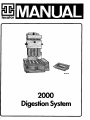
2000
Digestion System
Dansk
Teksten med sikkerhedsinformation er skrevet
i denne stil og oversat til de lokale sprog
(EU/EES). Informationen kan findes pa de gule
sider.
Deutscfl
Text uber Sicherheitsinformationen ist in
diesem Stil geschrieben und in andere
Sprachen (EU/EES) ubersetzt. Die
Informationen finden sich auf den gelben
Seiten.
English
Text regarding safety information is written
in this style and translated into local
language (EU/EES). The information will be
found on the yellow pages.
Kei|XEVO 7tA,r|po<|>opEi.c)v aac|)aA,eias ypa^exai C
c o u r i e r Kai |j.ETa(|>pa^ETai axr\v TOTUKTI yXcoaaa (EE/EES).
Oi 7iA,ripo(|)op8i8S evTO7ti^ovtai CTTO Xpuao OSrjyo.
Islenska
Texti sem vidkemur upplysingum um oryggi er
skrifadur i pessum stil og pyddur a
stadarmalid (EU/EES). Upplasingarnar ma finna
a gulu sidunum.
Espahol
El texto relativo a la informacion de
seguridad esta escrito en este estilo y
traducido al idioma local (EU/EES). La
informacion figura en las paginas amarillas.
Le texte concernant les informations sur la
securite est redige dans ce style et traduit
dans les langues nationales (EUROPE, EEE).
Ces informations se trouvent dans les pages
jaunes.
Italiano
II testo relativo alle informazioni di
sicurezza e scritto in questo stile e
tradotto nella lingua locale (EU/EES). Le
informazioni si trovano sulle pagine gialle.
Nederlands
De tekst inzake veiligheidsvoorschriften is
in het opgesteld en wordt in het Nederlands
vertaald. De informatie staat in de gouden
gids .
Norsk
Tekst som gjelder sikkerhetsinformasjon er
skrevet med denne stilen og er oversatt til
lokalt sprak (EU/EES). Informasjonen finnes
pa de gule sidene.
Portugues
0 texto sobre as informagoes de seguranca
esta escrito neste estilo e traduzido na
lingua local (EU/EES). As informagoes
encontram-se nas paginas amarelas.
to
I
I
§
•s
a
a
S
Suomilcsi
Turvallisuuteen liittyvat tiedot on
kirjoitettu talla tyylilla ja kaannetty
paikalliselle kielelle (EU/EES). Tiedot
loytyvat keltaisilta sivuilta.
Svenska
Text som har med sakerhet att gora ar skriven
med denna stil och ar oversatt till lokalt
sprak (EU/EES). Informationen hittas pa de
gula sidorna.
I
c
i5
g
8
Table of contents
SAFETY PRECAUTIONS AND PROCEDURES
5
1.1
1.2
Intended use
Safety precautions
5
5
2
INTRODUCTION
i
2.1
2.2
Brief description
Performance data
7
8
3
PREPARATIONS FOR USE
3.1
3.2
9
3.5
Unpacking and checking
Assembly
Exhaust System for individual handling of tubes for DS-6
Installation requirements
Input and output connections
2006, 2012, 2020 and 2040 Digester
2000 Controller
Flow Regulator
2001 Scrubber Unit
Fuses
2001 Scrubber unit
Installation instructions
Digestion Unit
Exhaust System
Flow Regulator
-Adjustment of the Flow regulator
Scrubber unit
Adjustment of Scrubber unit
Reagents for Scrubber unit
Water aspirator supplied with DS-6 and DS-12
Water aspirator supplied with Exhaust System for DS-20 and DS-40
Controller
Checking and changing set Digester type
Function
4
OPERATING INSTRUCTIONS
•B
4.1
4.2
4.3
(S
4.3.1
&
4.4
4.5
1
4.5.1
4.5.2
4.5.3
4.5.4
4.5.5
4.5.6
4.5.7
4.5.8
4.5.9
Identification of operating controls and symbols
Operation
Starting the Digestor
Changing the set temperature
Preparing samples before digestion
Programming the Controller
Starting the Controller
Programming the temperature and time cycles for the Digestor
Start of the Digestor
Setting the delay time
Scrubber Unit or Flow Regulator connected
Lift System connected
Interrupting the cycle
Example of Digestion with Flow Regulator or a Scrubber Unit
Digestor finishes heating
19
19
19
20
20
20
20
20
21
22
22
23
23
24
25
s
4.6
Handling of the tube rack
25
3.2.1
3.3
3.3.1
3.3.1.1
3.3.1.2
3.3.1.3
3.3.1.4
3.3.2
3.3.2.1
3.4
•8
AB,
4)
3.4.1
3.4.2
3.4.2.1
3.4.2.2
3.4.2.3
3.4.2.4
3.4.2.5
3.4.2.6
3.4.2.7
3.4.3
3.4.3.1
9
11
11
12
12
12
12
13
13
13
13
13
13
13
14
14
14
14
15
15
15
16
17
18
S
18
o
§
n
i
dim
1
E
i
tion
I
o
19
4.6.1
4.6.2
Before digestion
After digestion
25
26
5
MAINTENANCE
n
5.1
5.2
Cleaning of the Digestion tubes
Maintenance
27
27
5.2.1
5.2.2
5.2.3
5.2.3.1
Digestion system
Exhaust system
Scrubber Unit 2001
Pre-cleaning stage
27
27
27
28
5.2.3.2
Cleaning air pump
28
6
TROUBLE SHOOTING SCHEME
29
7
8
TECATOR APPLICATION NOTES SYSTEM
TECHNICAL SPECIFICATION
30
31
8.1
8.2
8.3
Safety
Environmental conditions
Storage and transport
31
31
31
9
SALES AND SERVICE
32
9.1
9.2
9.3
Complete Digestion system
Accessories and spare parts
Manufacturers name and address
32
34
36
10
SICHERHEITSINFORMATIONEN 2000(DE)
37
10
SIKKERHEDSINFORMATION 2000(DK)
43
10
INFORMACION DE SEGURIDAD 2000 (ES)
49
10
TURVALLISUUSOHJEET 2000 (Fl)
55
10
INSTRUCTION DE SECURITE 2000(FR)
6i
10
SAFETY INFORMATION (GB)
68
10
nAHPOOOPIES ASOAAEIAS (GR)
74
10
UPPLYSINGAR UM ORYGGI (IS)
si
10
INFORMAZIONI Dl SICUREZZA 2000(IT)
86
10
VEILIGHEIDSINFORMATIE 2000(NL)
92
10
SIKKERHETSINFORMASJON 2000(NO)
98
10
INFORMACOES DE SEGURAN^A 2000(PT)
104
10
SAKERHETSINFORMATION 2000(SE)
no
3
oo*
s
s
I
a
o
1
§
SAFETY PRECAUTIONS AND
PROCEDURES
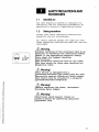
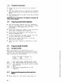
1.1
Intended use
The 2000 Digestion System is designed for
laboratory use for analysing parameters as
specified in Tecator's Application Notes.
1.2
Safety precautions
Please read these operating instructions
carefully and act accordingly.
For safety reasons people not familiar with
these operating instructions must not use the
instrument.
Warning
Careful handling of the solutions used in an
analysis is mandatory for laboratory safety.
Refer to the appropriate material safety
data sheet for reagent handling
instructions.
Eye protection should be worn at all times
and care should be taken when handling hot
digestion tubes.
Warning!
This device is equipped with a
grounding/earthing type power plug for your
protection against electrical shock hazard
and should only be attached to a properly
grounded/earthed receptacle.
Warning!
Before replacing the fuses, disconnect
incoming mains supply.
Warning!
Electrical shock hazard. Covers or
panel (s)should be removed by qualified
personnel only.
s
•1
/A
Hot surface!
Caution!
The responsible body shall be made aware
that, if the equipment is used in a manner
not specified by the manufacturer, the
protection provided by the equipment may bt
impaired.
Modifications, alterations, rebuilding or
use of safety parts not authorized by Tecator
AB violates the warranty. Tecator AB has no
responsibility for damages, material or
personal, occurring as a result of such
actions.
Note! To maintain the limits for the CE approval only CE approved
instruments may be connected.
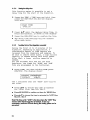
INTRODUCTION
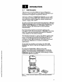
2.1
Brief description
This manual covers the different types of Digestion
Systems, Control Systems, Fume Removal Systems and
Accessories for digestion supplied by Tecator.
The basis of Tecator's Digestion Systems, is one of the
four Digestion Units (2006, 2012, 2020 and 2040). They
are convenient tools for digestion sample preparation
within a range of 50- 440°C .
To remove the fumes generated during digestion, different
Exhaust Systems can be combined with the digestor. By
adding a Flow Regulator or a Scrubber Unit to the
Exhaust System, the water flow can be controlled
automatically.
For eliminating emission of corrosive gases in the
laboratory and to the environment, a Scrubber should be
used. The unit also eliminates the need for a separate
water supply for the exhaust system.
The Digestion System is a part of the Kjeltec system and
can be combined with suitable Distilling and Titration
Units, to run determinations of nitrogen/protein in
accordance with official methods. It can as well be used
for other wet digestions in a number of different
applications.
To simplify the handling and timing, the 2015 Lift
System from Tecator can also be integrated with the
digestor.
By using the Controller, different time and
temperature cycles can be programmed to control the
digestor. The Lift system, the Scrubber or the Flow
Regulator can also be controlled, thus making a totally
automated digestion possible.
I
5
a
§
8
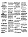
Fig. 1 A fully automatic Digestion System allowing unattended
operation.
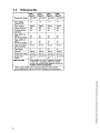
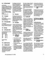
2.2
Performance data
2006
Digestor
2012
Digestor
2020
Digestor
2040
Digestor
Temperature range:
100-440°
C
100-440°
C
100-440°
C
100-440°
C
Temp, setting
repeatabilbity:
1°C
1°C
re
1°C
Temp, readout
Digital
Digital
Digital
Digital
Heater indication:
LED
LED
LED
LED
Overtemperature
protection
Yes
Yes
Yes
Yes
Temp, stability at
100°C
with the Controller:
±5
±2
±5
±2
±5
±2
±5
±2
Temp, stability at
400° C
with the Controller:
±3
±1
±3
±1
±3
±1
±3
±1
Heating time 20 to
400° C at 230 V:
30 min
30 min
40 min
40 min
Tubes/batch:
6
12
20
40
Tube size:
250 ml
100 ml
250 ml
100 ml
Sample size* solids:
up to 5 g
up to 1 g
up to 5 g
up to 1 g
Sample size*
liquids:
up to 15
ml
up to 3 ml
up to 15
up to 3 ml
2000 Controller
nil
Programmable in 9 steps. Temperature 20-440°
C. Time from 1 minute up to 99 hours and 59
minutes. Can control all the Digestors, the Lift, the
Scrubber and the Flow Regulator.
* Note: Larger samples require special procedures. Please see the
relevant Application notes or consult our Customer Service Laboratory.
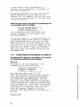
PREPARATIONS FOR USE
3.1
Unpacking and checking
Unpack the Digestion Unit and its accessories with care.
Remove all packing material from the equipment.
Use the packing list provided with the unit to check that
you have received all parts.
If you have any questions, please contact your Tecator
representative or Tecator.
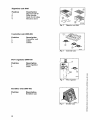
Digestion unit 2006
Position
1
2
3
Fig. 2
Description
Digestor DS-6
Heat shield
Rack for 6 tubes
Digestion unit 2006.
Digestion unit 2012
Position
1
2
3
4
Fig. 3
Description
Digestor DS-12
Heat shield
Rack for 12 tubes
Retainer plate
Digestion unit 2012.
Digestion unit 2020
n
Position
I
1
2
3
4
Fig. 4
Description
Digestor DS-20
Heat shields
Rack for 20 tubes
Retainer plate
Digestion unit 2020.
9
Digestion unit 2040
Position
1
2
3
4
Description
Digestor DS-40
Heat shields
Rack for 40 tubes
Retainer plate
Fig. 5
Digestion unit 2040.
Fig. 6
Controller unit.
Controller unit 2000-001
Position
1
2
3
Description
Controller unit
Cable
Cables
Flow regulator 2000-010
Position
1
2
Description
Flow regulator
Cable
1
i
Fig. 7
Flow regulator.
Fig. 8
Scrubber unit.
Scrubber Unit 2001-001
Position
1
10
Description
Scrubber unit
I
3.2
Assembly
The Digestion Unit itself comes fully assembled, but the
rack for the digestion tubes for DS-20 and DS-40 needs to
be assembled (see fig.9). First fasten the two handles in
the two upper pairs of holes in the rack. Use the screws
supplied. The handles are asymmetrical. Fasten them
with the flat side facing down. Then fasten the lower
plate for the rack in the lower holes. Use the screws and
nuts supplied.
Fig. 9
Tube racks for
digestion tubes, DS-20 and
DS-40.
3.2.1
Exhaust System for individual handling of tubes for DS-6
The Exhaust System for Individual Handling of
tubes for DS - 6 must be assembled as follows:
Use fig. 10 for reference.
a) Mount the exhaust cap stand, posl, in the predrilled
holes with two screws and two spacers. Attach the
stand to the rear of the Digestion Unit, using the two
screws supplied. Referring to fig.10, see that the stand
is attached correctly.
b) Moisten (with water) the six tubing connectors on the
glass exhaust receiver, pos2, and secure a short tube on
each outlet.
c) Slide the glass exhaust receiver into position in the
plastic holder. Turn the outlet towards the cold water
tap to which the Exhaust System later will be
connected.
Fig. 10 The Exhaust System for
individual handling.
d) Moisten the tubing connectors on the exhaust caps,
pos3, and attach the other end of the tubing. Cut off a
small piece of tubing if necessary, so that the exhaust
caps will rest safely in their holders on the upper part
of the exhaust cap stand.
e) Secure the long special tubing on the outlet to the
exhaust receiver.
<
f) The other end of this tubing is connected to the water
aspirator or scrubber unit.
I
o
g
11
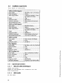
3.3
Installation requirements
This table is
translated.
2006 and 2012 Digestor
Power supply
200-230V or 100-115V, 50-60 Hz
Power consumption
1000W
Water supply: Exhaust
~5 l/min for 5 min then 1-2 l/min.
Not needed with Scrubber.
Weight
10kg
Dimensions, LxDxH
28x31x14 cm
Ventilation requirement
Exhaust system and Fume hood
Recommended bench space
0,6 m
2020 and 2040 Digestor
Power supply
200-230V, 50-60 Hz
Power consumption
1860W
Water supply: Exhaust
~5 l/min for 5 min then 1 -2 l/min.
Not needed with Scrubber.
Weight
19 kg
Dimensions, LxDxH
32x48x14 cm
Ventilation requirement
Exhaust System and fume hood
Recommended bench space
1 m or 0.4 m if a Lift is used
2000 Controller
Power supply
None, connects to the Digestor
Weight
0.6 kg
Dimensions, LxDxH
17x13x5 cm
Flow Regulator
Power supply
200-230V or 100-115V, 50-60 Hz
Power consumtion
15W
Weight
1.0 kg
Dimensions, LxDxH
10x10x15 cm
2001 Scrubber Unit
Power supply
100/110/200/230 V, 50-60 Hz
Power consumption
150W
Water supply
No
Weight
13 kg
Dimensions, LxDxH
340x330x340
Ventilation requirement
Connection to Fume hood possible
3.3.1
3.3.1.1
Input and output connections
2006,2012,2020 and 2040 Digestor
Under the front:
There is one Modular 8/8 connector for the
2000 Controller.
3.3.1.2
2000 Controller
At the rear:
12
There are two interchangeable Modular 6/6
connectors to control the functions of the
2015 Lift System, Flow Regulator, 2001
Scrubber Unit or Scrubber interface.
There is also one Modular 8/8 connector for
one of the 2000 series Digestor Units.
One 9-pin D-SUB for PC.
3.3.1.3
FlowRegulator
Under the front:
There is one Modular 6/6 connector for the
2000 Controller.
3.3.1.4
2001 Scrubber Unit
On the left side:
There is one cable with a Modular 6/6
connector for the 2000 Controller.
3.3.2
3.3.2.1
Fuses
2001 Scrubber unit
Choose the appropriate fuse in accordance
with the following table:
Primary fuses:
100V
2x T 3.15 A
110V
2x T 2.5 A
200V
2x T 1.6 A
230V
2x T 1.6 A
Secondary fuse:
T 2. 5 A
|
%
s
(2
i
3.4
Installation instructions
3.4.1
Digestion Unit
The Digestion System should always be used
together with an Exhaust System or a Reflux
Condensor and it must be installed close to a
cold water tap and appropriate power supply.
The connnections are: brown wire-line, blue
wire-neutral and green/yellow-protective
earth.
w
o
o
~
~
«
"
5
t
^
•|
|
Please check on the back of the unit that the
specified voltage agrees with the power
supply.
If a Scrubber unit (see Complete Digestion
System, section 9.1) is used, the water
supply is not necessary.
It is always recommended to place the system
in a fume cupboard if available.
13
3.4.2
Exhaust System
The Exhaust System consists of an exhaust
manifold, a water aspirator and a stand with
a drip pan for the exhaust manifold. An
optional Flow Regulator can be used in
conjuction with the Water Aspirator.
3.4.2.1
FlowRegulator
Connect the upper snap in part of the Flow
Regulator to the cold water tap (ordinary
diameter: 1/2"). An internal thread in the
upper part can be unscrewed to fit a water
tap with a larger diameter (3/4").
Then screw the water aspirator to the fitting
that is underneath the Flow Regulator.
Connect the mains cable to the wall socket.
3.4.2.2
The Exhaust Systems.
Adjustment of the Flow regulator
•
Press the switch to position I.
•
Open the water tap to the maximum flow
that will be used for the 'High' flow
during digestion.
•
Turn the knob counter-clockwise to the end
postion.
•
Press the switch to position II.
•
Turn the knob clockwise to the flow that
will be used for the 'LOW flow during
digestion.
It is preferable to make the last adjustment
during the first digestion performed.
After the time for the 'High' flow has
passed, press the switch to position II.
Please note that the knob must be turned
completely to the end position. Then adjust
to the flow that is to be used. The Flow
Regulator can, after the initial adjustment,
be controlled from the controller 2000 when
the switch is in the 0 position.
3.4.2.3
Fig. 11
Fig. 12 The Flow Regulator
and the Water Aspirator (broken
line).
*>•
$
Scrubber unit
Please check at the back of the unit that the
specified voltage agrees with the power
supply. Connect the Scrubber to the socket.
Connect the tubing on the top of the unit to
the exhaust manifold. If desired, a
ventilation tube can be connected from the
outlet of the unit to a fume hood or another
suitable ventilation system.
«**
\
it
J
ttgd
I
\
s
a
a
.2
Bloc064a
s
Fig. 13
14
The Scrubber Unit.
to
a
o
•43
3.4.2.4
Adjustment of Scrubber unit
The Scrubber can be manually operated.
Switching from high to low exhaust settings
can easily be done using the switch on the
left side of the unit.
Press the switch to position II for maximum
suction, high exhaust, during the initial
part of the digestion.
For reduced suction, exhaust low, press the
switch to position I. Regulate the suction
with the lever on the right side of the
Scrubber Unit, to the suction level where the
fumes just are retained in the tube. Watch
for the condensation inside the tube. It is
preferable to make the last adjustment during
the first digestion being performed with the
Scrubber unit. For automatic operation the
switch must be set in 0 position, see section
4.5.5
3.4.2.5
Reagents for Scrubber unit
The Scrubber unit operates with an air pump
that transports the evaporated fumes first
through an acid trap (left flask) and then to
a neutralizing solution (right flask). The
air flow is ventilated through an outlet on
the rear.
Note! The cap with an extra splash plate fitted should be used
with the flask to the right.
|
|
m
I
|
ss
1
§
|
Neutralising solutions:
The condensation flask to the left should be
filled, to the minimum level with water, to
preclean the gases and to prolong the
lifetime of the scrubber reagents.
The flask to the right should contain a
solution of 0.4 litre sodium hydroxide (40%)
and 0.8 litres of water. This solution is
sufficient for up to 100 Kjeldahl digestions,
i.e. 5 batches of 20 250 ml tubes. To have a
secure way to know when the neutralising
solution is saturated a suitable acid/base
indicator can be added, i.e. bromothymol
blue, BTB.
PH
|
Note! The flask to the right should not be filled above the
maximum level.
|
3.4.2.6
•|
|
4
s
Connect the water aspirator to the cold water
tap (ordinary diameter: 1/2") or the Flow
Regulator. The upper part can be unscrewed to
fit a water tap with a larger diameter (3/4") .
Water aspirator supplied with DS-6 and DS-12
15
A piece of tubing (not supplied) attached to
the lower part of the water aspirator and
directed down into the sink drain will
considerably reduce the noise level.
3.4.2.7
Water aspirator supplied with Exhaust System for DS-20
and DS-40
Alternative I , see fig. 14
Connect the water aspirator directly to the
drain pipe (5) with a piece of tubing (1)
(not supplied) . Note that the waste pipe must
have an air outlet (6) somewhere to prevent
counter-pressure in the tubing (1).
Alternative II, see fig.15
Fig. 14 Alternative I
The lower part of the water aspirator is put
through a cover (2) over the sink. The air is
led out through a hole in the cover via a
piece of tubing (3) connected to a fume
cupboard or a vent. The diameter of this
tubing should be about 40 mm. The ventilation
tubing (part no 1000 0516) can be used.
For both alternatives the tubing supplied
with the Exhaust System should be connected
from the manifold to the vacuum connection
(4) on the water aspirator. Cut the tubing as
short as possible. It should be just long
enough so it can be operated during digestion
without bends or kinks. Make sure that the
manifold can be placed on the digestion tubes
when the tubes are placed in the block and
that it is possible to lift out the tubes
onto the cooling rack with the manifold still
in place. The exhaust must also be used
during the cooling stage.
Fig. 15 Alternative II
Now choose the most convenient location for
the Digestion unit on the laboratory bench,
or in a fume cupboard. The maximum distance
to the cold water tap should be the length of
the long tubing, but preferably shorter.
It is important for the proper function of
the exhaust system that the tubing from the
exhaust receiver to the water aspirator does
not form any bends or kinks.
Because acid will condense in the tubing
during the digestion, cut off the long
special tubing to a suitable length and
connect it to the water aspirator.
3.4.3
Controller
The Controller draws its power from the
connected Digestor.
Connect the cable with the 8-pin contact, in
the front underneath the cabinet of the
Digestion Unit, to E on the Controller unit
16
PS
•3
(see figs.16 and 17 ) .
When the Lift System is to be connected with
the Controller, use the contact that is
situated on the back of the Lift Unit. The
Flow Regulator and the Scrubber both have
communication contacts on the front. For all
alternatives, you must connect the 6-pin
contact cable to either A or B.
There are two alternative locations for the
controller. It is delivered to be placed on
Fig. 16 The Digestion Unit seen
the laboratory bench. If the controller is to
from the front underneath the cabinet. be placed on the wall, unscrew the four nuts
that hold the plate at the back of the unit.
Then turn the plate 180 degrees and screw
back the four nuts.
u
A B
HH
c
I
u
OW.V.'IO
o|[jl]|
D E
i
BLOCW f t
Fig. 17 The rear of the controller.
A and B: to Lift System or to Flow
Regulator or to Scrubber Unit
C: to PC
D: adjustment of contrast of display
E: to Digestion Unit
Note! Avoid placing the controller in the fume cupboard as
accidental spillage of acid can cause damage.
3.4.3.1
Checking and changing set Digestor type
When you turn on the power you will see the
type of Digestor that is preprogrammed for a
few seconds in the display:
TECATOR
DS-XX
V.ZZ.ZZ ==*==000000
To check the type of Digestor that is
preprogrammed, proceed as follows:
•
Press TEMP, and while holding TEMP, press
RUN/STOP
•
The display shows in this example that the
controller is set for a DS-20 :
TECATOR
00 06
DS-20
12 *20* 40
If the Digestor type shown in the display of
the Controller is not the Digestor that is to
be used, the following steps have to be taken.
a
a
I
e
•
Press the A T button, up or down, to
change the Digestor type.
•
Press RUN/STOP to confirm set Digestor
type, and then the Controller returns to
the working menu:
#: 1
STOP
T: XXX
ZZZ
YY:YY
Note! *00* is used when heat sources other than Tecator
Digestors are connected to the Controller.
a
.2
17
3.5
Function
The different Digestors are designed for temperatures
from 50°C to 440°C. All four Tecator Digestors can be
integrated in systems to make the digestion more
automatic.
The Flow Regulator makes it easy to adjust the flow
through a connected water aspirator. It can be set to three
different positions where the flow is either at a
maximum, minimum or no flow at all through the water
aspirator. This can be controlled automatically by the
Controller Unit.
The Scrubber Unit eliminates emission of corrosive
exhausts to the laboratory environment and the
atmosphere. The unit also makes it possible to operate
the exhaust system without the need for a water supply.
The Scrubber unit can be operated manually or controlled
automatically by the Controller Unit.
The use of a Lift System minimizes the manual handling
during the digestion. This system also secures that close
control of the digestion conditions is obtained i.e.
digestion time will always be the same.
The 2000 Controller Unit is used together with the
Digestion unit types 2006, 2012, 2020 and 2040 as well as
the Lift System, the Scrubber Unit and the Flow
Regulator.
The Controller is programmable in nine steps, and both
temperature and time can be set.
When a Lift System is integrated with the Digestion Unit,
the start and stop steps of the Lift System are controlled.
When a Scrubber or a Flow Regulator is integrated, their
procedures are programmed into the Controller Unit.
OPERATING INSTRUCTIONS
4.1
Identification of operating controls and symbols
These tables are translated.
Fig.18 Operating controls Digestors
1
Fig. 18
The Digestors.
Power
2
Heating indicator lamp
3
Select set point
4
Increase set value
5
Decrease set value
Fig.19 Operating controls Controller
Fig. 19
1
Increase
2
Decrease
3
Run/Stop
4
Select temp
5
Select time
Fig.2O Operating controls Flow Regulator
1
Operation mode selector
2
Flow rate adjustor
4.2
BLOC070a
Fig. 20
The Flow Regulator.
Operation
Tecator's Digestion Systems can be used for a
number of different types of analysis. •
Application Notes are available from your
Tecator representative upon request.
Note! Most digestion applications involve strong chemicals and
high temperatures, which makes it important to follow the safety
regulations. Always protect your eyes and use protective gloves
and garments.
4.3
Starting the Digestor
•
Press the mains switch to start the
Digestor.
•
The set temperature is displayed for one
second, followed by the actual temperature
in the Digestor.
•
If the actual temperature is lower than
the set value, a steady light will appear
in the heating indicator lamp, see fig.18,
showing that the Digestor is heating.
•
When the set temperature is reached in the
Digestor, the heating indicator lamp will
flash.
10
a
o
g
§3
19
4.3.1
Changing the set temperature
•
Press and hold the function key marked
•
The set temperature is changed by pressing
and holding down the function keys marked
• T.
•
The maximum value is 440°C and the minimum
value is 50°C.
Note! If there is any malfunction in the Digestor, the display will
show an error message.
4.4
Preparing samples before digestion
•
Add the weighed sample and the chemicals
and/or the reagents to the digestion tubes
according to the application to be
performed.
•
Place the digestion tubes in the tube rack
and place it beside the Digestor.
•
Check that the Digestor has reached the
correct temperature.
•
If the Controller is used, check that the
correct settings are programmed.
•
Turn on the water tap fully or as the
application requires.
•
Hang the heat shields in position on the
rack.
4.5
Programming the Controller
4.5.1
Starting the Controller
When the Digestor is switched on, the
Controller will beep and go through a check
routine for some seconds before the working
menu is shown in the display:
a
#:1 T: XXX
STOP
ZZZ
YY:YY
I
00*
s
#:1 = The first step, always shown first
XXX
= Set temperature for the first step
YY: YY = Set time for the first step in hours
and minutes
STOP = Stop
ZZZ
= The actual temperature in the
Digestor
&
"
&
1
|
J
2
4.5.2
h
J
en
3
§
•
20
Programming the temperature and time cycles for the
Digestor
After Power On, the first step shown is
I
#1 T: XXX
STOP
ZZZ
YY:YY
•
By pressing A T , the desired step is
chosen
•
When the desired step is reached and shown
in the display, the temperature and time
can be set for that step.
Changing the temperature:
•
Press and hold TEMP, press A T to the
desired temperature. Max 440°C, Min 10°C.
Note! The set temperature in the Digestor must be equal to or
higher than the highest temperature in any cycle.
Changing the time:
•
Press and hold TIME, press A T to the
desired time. Max 99:59, Min 00:00
Note! When holding down A T and scrolling, the digits will start
moving faster after some seconds.
When the desired temperature and time are set
for this step, the next step can be set. The
procedure is repeated for up to 9 steps.
Note! A step where the time is set to 00:00 is called a stop step.
The programmed cycle will stop at this step and the set
temperature will be maintained
To run the digestor at a constant temperature
for a prolonged time set the temperature to
the desired value and program the time to
00:00 and press run. The set temperature will
be maintained until shut-down of the system.
|
|
«
It is possible to preprogram several cycles
starting from different steps if stop steps
are used.
o
|
4
0
|
^
£
•*
The function of the step/time programming is
as follows:
The time for first step in any cycle is
always measured from the point where the
digestor have reached the set temperature. In
all other following steps, time is always
measured directly from the start.
1
s
|
|
|
a
|
I
4.5.3
Start of the Digestor
See 4.6 regarding handling of the tube rack
before digestion. The Digestor starts to heat
up when the RUN/STOP button is pressed and it
does not matter which step is choosen.
Note! The count down for the first programmed step starts when
the preset temperature is reached.
bo
3
g
21
4.5.4
Setting the delay time
This function makes it possible to set a
delay time for the start of the digestion.
•
Press the TEMP + TIME keys and hold, then
press the RUN-STOP key and the display
will show.
DELAY TIME
T=00:00
•
Press A T until the desired delay time, in
hours and minutes, is shown in the display.
•
Press the RUN-STOP key to confirm the time.
•
The delay time settings will be cleared
after each cycle.
4.5.5
Scrubber Unit or Flow Regulator connected
During the first 10 to 15 minutes of the
digestion, depending on application, a
considerable amount of fume vapours are
released from the chemicals and samples. To
be able to remove these fumes, a high suction
capacity is needed during this first phase.
After that, a lower suction capacity is
needed.
For the Scrubber Unit and for the Flow
Regulator, the times for 'HIGH' and 'LOW
flow are programmed in the Controller.
Press TIME, and when holding TIME press
RUN/STOP. The display shows:
EXHAUST PARAMETERS
*HIGH=YY
LOW=ZZ
The * indicates that the 'HIGH' flow will be
set first.
«
»
o
i
•
Press A • to choose the time in minutes
for 'HIGH' flow. Max 180, Min 0
•
Press RUN/STOP to confirm set time for 'HIGH' flow.
S
S
§
H
•
Press A • to choose the time in minutes for 'LOW flow.
Max 59 , Min 0
Note! The time set for "LOW" is the time where the "LOW" flow
remains after that the digestion is finished. In this way
unnecessary emission of fumes during the cooling phase can be
prevented.
J
j
|
§•
|
§
.Sf
n
22
Press RUN/STOP to confirm and store the
chosen times and the Controller returns to
the working menu:
#:1 T: XXX
STOP
ZZZ
4.5.6
YY:YY
Lift System connected
The Lift System is started when the
temperature programmed for the start step is
reached in the Digestor. The tube rack with
the tubes moves up and docks with the exhaust
manifold or the reflux head. The complete
assembly is lowered into the block and the
digestion proceeds for the programmed cycle.
Note! When DS-40 is used, it is preferable to dock the exhaust
manifold or the reflux head manually.
The Lift stop signal comes when the
Controller reaches a step where the time is
set to 00:00. The complete assembly will then
be raised to its top position.
Program example:
First Stfcps
Second sst«£>;
g
"8
m
9
S
TE&H? ~ 420
TIME » Olr-OQ
TSMP ** 10-
TIME « O0;OG
• When the temperature in the Digestor has
reached 420°C, the complete assembly will
be lowered into the Digestor.
• After 1 hour, step number two is
activated, and as the time is 00:00, the
complete assembly will rise in the Lift
system.
• The Digestor will cool down to room
temperature when the temperature is set to
10.
3
f•jjj
|
0
£
3
1
• A step when the time is set to 00:00 is
called a stop step. In this step the
Digestor will maintain the set
temperature.
• You can reach a stop step in a cycle or
choose a step with time 00:00, and press
run.
g
4.5.7
Interrupting the cycle
|
4
f
f
I
|
The cycle can be interrupted by pressing
RUN/STOP. The tube rack with the Exhaust
Manifold or the Reflux Head will rise to the
top position in the lift and the flow will
continue through the Flow Regulator or
Scrubber Unit for the programmed time.
23
If some button other than RUN/STOP is
pressed, the Flow Regulator or Scrubber unit
will stop immediately.
By pressing RUN/STOP, the tube rack and the
Exhaust Manifold or Reflux Head will be
lowered into the digestor, and the cycle will
continue from the beginning of the step where
it was interrupted.
Note! If the power supply is interrupted, The Controller beeps and
a warning will be shown in the display:
CYCLE HALTED DUE TO
POWER INTERRUPTION
For a combination with Controller, Lift
System, scrubber Unit and Digestor the
following happens:
If the power supply is interrupted during an
unattended digestion the tubes will remain in
the block and the block will cool off. When
power comes back, the Lift System will lift
the tubes out of the block and remain in that
position until manual action is taken and the
block will not start to heat. The Scrubber
Unit will start with reduced suction for the
programmed time.
4.5.8
Example of Digestion with Flow Regulator or a Scrubber Unit
Note! When the Flow Regulator or the Scrubber Unit is connected
to a Controller the switch must be in the O-position.
With Lift
Settings for the Flow Regulator or the
Scrubber Unit in the Controller:
EXHAUST PARAMETERS
*HIGH=10 LOW=15
The digestion time is set at 01:00
After the RUN/STOP button has been pressed to
start the digestion cycle and the Digestor
has reached the set temperature, the Lift
will lower the complete assembly into the
Digestor. At the same time the Flow Regulator
or the Scrubber Unit starts the 'HIGH' flow,
which continues for 10 minutes. The remaining
digestion time will have a 'LOW flow. After
the digestion is completed, the Lift will
raise the complete assembly to the top
position. The 'LOW flow will continue for 15
minutes.
5
§
~
5
f*
"
«
|
s
-|
|
~
s
to
Without Lift
24
I
Settings for the Flow Regulator or the
Scrubber Unit in the Controller:
EXHAUST PARAMETERS
*HIGH=10 L0W=15
The digestion time is set at 01:00
When the Digestor has reached the set
temperature, the Flow Regulator or the
Scrubber Unit starts at a 'HIGH' flow, that
will continue for 10 minutes. The tube rack
is then lowered manually into the block.
After the 10 minutes have passed, the flow
will continue with a 'LOW flow for the rest
of the digestion time. When the remaining
digestion time has passed, the tube rack must
be lifted out from the Digestor manually, and
the 'LOW' flow continues for 15 minutes.
4.5.9
Digestor finishes heating
The Digestor will stop heating when it
reaches a stop step where the temperature
setting is lower than the ambient temperature.
4.6
Handling of the tube rack
4.6.1
Before digestion
With Lift System
|
|
«
•
Make sure that the rack is filled with
tubes, even if not all contains a sample.
Otherwise the performance of the Exhaust
Manifold or Reflux Head will be impaired.
•
Check that the correct timing is set for
the Lift System or for the Controller Unit.
•
Regulate the vacuum/flow rate for the
Exhaust Manifold/Reflux Head during the
digestion as described in the application
that is performed.
t-,
|
^
• When using the Reflux Head make sure that
the cooling capacity is enough.
CO
i
• Start the Lift System.
o
o
I
«
Without Lift System
^
5
I
s
|
I
I
• Place the Exhaust Manifold or the Reflux
Head on top of the digestion tubes. Make
sure that the rack is filled with tubes,
even if not all contains sample. Otherwise
the performance of the Exhaust Manifold or
Reflux Head will be impaired.
• Place the whole rack in the Digestor.
• Regulate the suction of the Exhaust
Manifold/Reflux Head to what is required
for the application being performed.
m
a
25
•
When using Exhaust caps place the cap on
top of the digestion tube. To have the
most effective exhaust, each cup should be
placed on a tube, even if the tube does not
contain any sample. Alternatively insert a
rubber plug in the unused caps.
Note! If the airflow through the Exhaust Manifold or Exhaust
caps is too high, there is a risk of evaporating acid and/or
reagent. This may cause a loss of nitrogen or of the parameter
being analysed.
4.6.2
After digestion
With Lift System
•
After the programmed time is over, the
tube rack with Exhaust manifold rises to
cooling position.
•
To prevent acid from dripping onto the
Digestor, the drip tray should be in place
before removal of a rack, when no
digestion is being performed.
Without Lift System
•
When the digestion is complete, lift the
tube rack out, with the Exhaust Manifold
still in place, and put it on the optional
cooling stand or onto a heat resistant
material. For rapid cooling, a small fan
may be used.
•
After the cooling, place the Exhaust
manifold onto the stand (including the
drip pan) to prevent acid from dripping
onto the surface underneath. Turn off the
water tap.
s
a
26
AAAINTENANCE
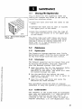
5.1
Cleaning of the Digestion tubes
Fig.21 shows how the digestion tubes can
easily be cleaned and dried in the rack by
using the retainer plate.
a)Place the tube rack with the tubes on the
bench.
b)Elevate the tube rack so that it touches
the upper part of the tubes.
c)Hook the retainer plate over the rims of
the tubes and attach it to the upper part
of the stand.
Fig. 21 The rack when using the
retainer plate.
The whole tube rack with tubes can now be
turned upside-down and cleaned with water
through a piece of tubing connected to a
water tap. Or it may be placed in a
laboratory dishwasher.
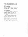
5.2
Maintenance
5.2.1
Digestion system
The Digestion System requires very little
maintenance apart from the daily wiping off
of any acid drops from the unit itself.
5.2.2
Exhaust system
The Exhaust manifold can be rinsed from acid
by filling the plastic drip pan (supplied
with the Exhaust system) with water.
•
Open the water tap for the aspirator fully
and immerse the caps of the Exhaust
Manifold in the water. The water will then
be sucked through the caps.
•
Let the manifold dry before the next
digestion. Also make sure that no water is
left in the tubing.
•
Open the water tap fully and raise the
manifold for some seconds.
This procedure should be done at regular
intervals to keep the system in good function.
5.2.3
'•§
Scrubber Unit 2001
The reagents in the flasks must be exchanged
when they are exhausted, i.e. when the pH of
the alkali solution is too low (pH<7). A
cleaning of the two flasks shall be made at
regular intervals, i.e. 100 digestions. Fill
27
the flask with water and dissolve all
crystals. Repeat the procedure two to three
times.
To obtain best performance the seals in the
flasks should be greased with regular vacuum
grease.
5.2.3.1
Pre-cleaning stage
The flask to the left should be filled to the
minimum level with water. The water traps
acidic fumes there by increases the useful
life of the reagents in the scrubbing stage.
5.2.3.2
Cleaning air pump
It is normally not necessary to clean the air
pump unless the neutralising flask
accidentally has been filled above the
maximum level and liquid has been sucked into
the air pump. If this happens it will not
cause permanent damage to the pump but it has
to be cleaned.
To clean the air pump proceed as follows:
1. Disconnect the Scrubber from the power
supply.
2.Remove both flasks.
3.Connect a hose from the air outlet on the
rear to a sink.
4.Gently rinse the pump with water through
the rightmost nipple on the front of the
unit, i.e. outlet of the neutralising flask.
s
a
a
28
TROUBLE SHOOTING SCHEME
Digestion systems
Fault
Lamp in main switch lit up
but not the display.
The display shows a very low
value for two minutes ,then
shows one zero in the middle.
The display first shows
nothing, then one zero in the
middle.
The display does not show
the set temperature the first
second after power but
shows 100°C instead.
The lamp in the main switch
and the display lights up but
the digestor does not get hot.
Controller
Fault
The Controller does not start.
The unit beeps at intervals
of one sec.
The unit does not remember
the last set value.
CO
<
Probable cause
The temperature cut-out
thermostat.
The temperature
transmitter is broken.
The temperature has
exceeded 450°C.
Corrective measure
Try to restore the cut-out
thermostat or contact your
service engineer.
Contact your service
engineer to replace the temp
transmitter.
Restore by turning off and on
again.
The EE-prom is broken.
Contact your service
engineer to replace the
circuit board.
The semiconductor relay or
the rod heater or a
connection problem.
Check the cables or contact
your service engineer.
Probable cause
Connection problem.
Program fault
Corrective measure
Check the cables.
Change unit.
The EE-prom is broken.
Contact your service
engineer to replace the
circuit board.
Contact your service
engineer to replace the
circuit board.
The function keys get stuck.
The circuit board is broken.
Flow Regulator
Fault
The unit does not react to
the control signals.
Probable cause
Connection problem.
Corrective measure
Check that the water tap is
turned on and check the
cable.
29
TECATOR APPLICATION NOTES
SYSTEM
For information about preparation of chemicals and the
Fibertec method please see the Application Note AN 300
supplied with your system.
In Tecators extensive list of Application Sub Notes you
will find information on how to analyse the sample of
your choice. Please contact your Tecator representative
for more details.
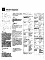
tecator I
APPLICATION
SUB NOTE
THE DETERMINATION OF NITROGEN ACCORDING TO KJELDAHL IN CEREALS
Sample Preparation
Grind the samples by using a suitable laboratory mill (Tecator Cyclotec) or grinder (Tecator Knifetec
Mill). Weigh 1 g of sample to an accuracy of ± 0.1 mg into a 250 ml digestion tube.
Digestion
Add 2 Kjeltabs Cu 3.5 (or 7 g K2SO4 + 0.8 g CuSO4 x 5H2O). Add 12 ml concentrated H2SO4.
Shake gently to "wet" the sample. Position the exhaust and turn on aspirator or scrubber. Digest for 60
minutes. Remove rack with exhaust and leave to cool for at least 15 minutes.
Distillation
On some systems part or all of this is performed automatically. Dilute cooled digest with 75 ml H2O.
Add 25 ml of receiver solution to receiver flask. Add 50 ml 40 % NaOH to diluted digest. Allow
reaction to settle (delay). Distil for the prescribed time (see below) and titrate distillate with
standardised titrant*.
T h e normality of the titrant is required to 4 decimal places. Perform a reagent blank before each
batch of samples.
Calculation
(T-B) x 14.007 x N x 100
% Nitrogen =
Sn
Weight of sample (mg)
I
% Protein = % Nitrogen x 6.25 (5.7 for wheat)
00
s
T = Sample titration B = Blank titration N = Normality of titrant
Settings
For details see system manual. Preheat Digestion Block to 420° C. Adjust exhaust to just contain
fumes after 5 minutes at full effect.
Model
Dilution
1002
1026
1030
1035
75 ml
75 ml
75 ml
75 ml
Fig. 22
Alkali
Delay
Distil
Rec Soln.
Titrant
02
Auto
12 sec
4 in ins
3.6
Auto
Auto
4% H3BO3
4% H3BO3
1%H3BO3
1%H3BO3
0.1 NHC1
0.1NHC1
0.1NHC1
0.1NHC1
lstroke
2
Macro
50 ml
Example of an Application Sub Note.
I
§
8
30
TECHNICAL SPECIFICATION
8.1
Safety
The insulation of external, inaccessible
circuits is reinforced.
8.2
Environmental conditions
The equipment is designed to be safe at least
under the following conditions:
•
Indoor use
•
Altitude up to 2000 m.
•
Temperature 5° C to 40° C.
•
Maximum relative humidity 80% for
temperatures up to 31°C decreasing
linearly to 50% relative humidity at 40°C.
•
Mains supply voltage fluctuations not
exceeding ±10% of the rated voltage.
•
Transient overvoltage is according to
category II which is normal for this type
of equipment.
•
Pollution degree 2.
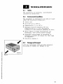
8.3
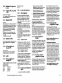
Storage and transport
Lift the instrument 2020 and 2040 Digestor
according to figure 23. Weight 19 kg.
9
Fig. 23
1
s
s
31
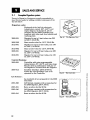
SALES AND SERVICE
9.1
Complete Digestion system
Tecator's Digestion Systems are easily expandable to
meet future needs by adding suitable components from
the list below.
Digestion units:
Equipped with a built-in electronic
temperature control 100°- 440°C and
digital display. As standard, all are
prepared for the 2000 Controller and
complete with tube rack, heat shields and
washing plate.
2006-001
Digestor for up to 6 test tubes, size 250
ml.230 V, 50-60 Hz.
2006-002
Same as above but for 115 V, 50-60 Hz.
2012-001
Digestor for up to 12 test tubes, size 100
ml. 230 V, 50-60 Hz
2012-002
Same as above but for 115 V, 50-60 Hz
2020-001
Digestor for up to 20 test tubes, size 250
ml. 230 V, 50-60 Hz.
2040-001
Digestor for up to 40 test tubes, size 100
ml. 230 V, 50-60 Hz.
Control Systems :
2000-001
'Controller with nine programmable
temperatures, 50°- 440°C, and time steps.
May be used in combination with any of
the Digestors. Powered from the Digestor.
Scrubber Interface. 230V, 50-60 Hz.
2000-013
Allows the 1013 Scrubber Unit to be
operated by the Controller.
Fig. 24
The Digestion Unit.
Fig. 25
The Controller.
Fig. 26
The Lift System.
Lift Systems :
2015-020
2015-021
2015-040
2015-041
As standard, all are prepared for the 2000
Controller
Lift System complete with accessories for
the 2020 Digestor, 230 V, 50 Hz
Same as above but for 60 Hz
Lift System complete with accessories for
the 2040 Digestor, 230 V, 50 Hz
Same as above but for 60 Hz
Si
a
32
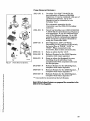
Fume Removal Systems:
Scrubber Unit 230 V, 50-60 Hz for
neutralization of fumes in Kjeldahl
digestions. It can be combined with any of
the Exhaust Systems. Up to two
Digestors can be connected to one
Scrubber Unit.
For automatic operation by the
Controller, use the 2000-013 Scrubber
Interface.
2001-001 B Bench top Scrubber unit 100/110/200/230
V, 50-60 Hz for neutralization of fumes in
acid digestions. It can be combined with
any of the Exhaust Systems. Up to 100
samples without replenishing reagents.
Fully automatic operation obtained by
using the Controller 2000.
2000-010 C Flow Regulator. 230 V, 50-60 Hz.
Depending on the position of the switch,
the water flow is "HIGH'V'LOW" or
"STOP". When connected to the
Controller, this is done automatically.
2000-011 C Same as above but for 115 V.
2006-020 D Exhaust System for the 2006 Digestor,
complete with water aspirator
2006-021 E Same as above but designed for easy
handling of each individual tube,
complemented with a special tube rack
for this purpose.
2012-020 F Exhaust System for the 2012 Digestor,
complete with water aspirator
2020-020 G Exhaust System for the 2020 Digestor,
complete with water aspirator **
2040-020 H Exhaust System for the 2040 Digestor,
complete with water aspirator **
** Can easily be mounted on the Lift System
1013-101 A
Fig. 27
I
Fume Removal Systems.
Note! All the Exhaust Systems are prepared for connection to the
2000-010 Flow Regulator.
I
s
k
a
§
33
9.2
Accessories and spare parts
Test Tubes :
Straight model (fig. A), often used for Kjeldahl
determination.
1000-0155
1000-0158
1000-0825
1000-0735
Size 250 ml, set of 6
Same as above, but set of 20
Size 100 ml, set of 12
Same as above, but set of 40
With constriction and volume mark (fig. B), used in
applications where the digest is diluted to volume and an
aliquot is taken for tests.
1000-0154
1000-0157
1000-0826
1000-0737
Volume mark at 250 ml, set of 6
Same as above, but set of 20
Volume mark at 100 ml, set of 12
Same as above, but set of 40
With a ground joint (fig. C) for air-cooled reflux condensers
1000-0156
Size 250 ml, set of 6
1000-0159
Same as above, but set of 20
Fig. 28 The different models of
test tubes.
With a ball joint (fig. D) for water-cooled reflux condensors
1000-0610
Size 250 ml, set of 6
1000-0611
Same as above, but set of 20
1000-0627
Size 100 ml, set of 12
1000-5523
Same as above, but set of 40
Reflux Condensors:
2006-030
2012-030
2020-030
Reflux head with 6 water-cooled
condensors for 250 ml tubes
Reflux head with 12 water-cooled
condensors for 100 ml tubes
Reflux head with 20 water-cooled
condensors for 250 ml tubes ***
lift I
1
^0
Fig. 29
jm
\i ®_ra
zd
P=
IKEI
I""
Reflux Condensors.
*** Can easily be mounted on the Lift System
1
I
c
a
o
1
34
Kjeltabs :
1527-0003
1527-0004
<
1527-0018
1527-0001
Fig. 30
Kjeltabs.
1527-0033
1527-0034
All types are delivered in boxes of 1000.
Selenium, tablets with 3.5 g K2SO4 + 3.5
mg Se.
Mercury, tablets with 3.5 g K2SO4 + 175
mgHgO
Copper, tablets with 3.5 g K2SO4 + 400
mg CuO x 5 H2O
Selenium, tablets with 1.5 g K2SO4 + 7.5
mgSe.
Mercury, tablets with 1.5 g K2SO4 + 75
mg HgO
Copper, tablets with 1.5 g K2SO4 + 150
mg CuO x 5 H2O
Handling Systems:
One each of the listed items below is included in the
corresponding Digestor. For handy operation it is
advisable to order more Tube Racks so that all the tubes
normally in use in the laboratory are placed in a rack.
1000-0831
1000-0573
1000-4237
1000-0072
1000-0536
Fig. 31 The different tube racks
and the stand for rapid cooling.
1000-0188
1000-0538
1000-4424
1000-0095
Tube rack for 6 tubes, 250 ml
Tube rack for 12 tubes, 100 ml
Tube rack for 20 tubes, 250 ml. This rack
fits the 1038 Sampler.
Tube rack for 40 tubes, 100 ml
Heat shields for the tube racks with 6 or
12 test tubes.
Heat shields for the tube racks with 20 or
40 test tubes.
Retainer plate for simultaneous washing
and drying of 12 tubes in their rack.
Retainer plate for simultaneous washing
and drying of 20 tubes in their rack.
Retainer plate for simultaneous washing
and drying of 40 tubes in their rack.
For convenient operation the Digestion System could be
complemented with the following accessories.
1000-0012
1000-0897
1000-0817
1000-0424
1000-0460
Tube rack for individual handling of up to
6 tubes, 250 ml. Recommended for
"express" samples when a 2006 Digestor
is used. (Included in 2006-021).
Handling device for test tubes.
Stand for rapid cooling when racks with 6
or 12 tubes are used.
Stand for rapid cooling when racks with
20 or 40 tubes are used. This is not
needed when the Lift System is used.
Boiling rod, to avoid bumping when
digesting large volumes of water.
35
1521-0001
1521-0002
Dispenser for reagents like acid or
peroxide. Adjustable 1-10 ml, (1250).
Dispenser for reagents like acid or
peroxide. Adjustable 10 - 30 ml, (2000).
Scrubber unit:
1000 6401
1000 6390
1000 6757
1000 6758
1564 0049
1564 0073
1564 0097
9.3
Flask
Lid cpl.
Set of o-rings
Membrane kit for pump cpl.
Fuse, T 1.6 A
Fuse, T 3.15 A
Fuse, T 2.5 A
Manufacturers name and address
Tecator AB
Box 70
S-263 21 Hoganas
Sweden
Int phone. +46 42 361500
Int fax. +46 42 340349
•s
$
M
36
SAFETY INFORMATION (GB)
10.1
Intended use
Warning!
The 2000 Digestion System is designed
for laboratory use for analysing parameters as specified in Tecator's Application
Notes.
Electrical shock hazard. Covera or
panel(a)should be removed by qualified personnel only.
10.2
/m\
Safety precautions
Please read these operating instructions
carefully and act accordingly.
For safety reasons people not familiar
with these operating instructions must
not use the instrument.
Warning
Careful handling of the solutions
used in an analysis is mandatory for
laboratory safety. Refer to the appropriate material safety data sheet for
reagent handling inatructiona.
Eye protection ahould be worn at all
times and care should be taken when
handling hot digestion tubes.
Warning!
This device is equipped with a
grounding/earthing type power plug
for your protection against electrical
shock hazard and ahould only be attached to a properly
grounded/earthed receptacle.
! \ Warning!
Before replacing the fuses, disconnect incoming mains supply.
Hot surface!
28x31x14 cm
Ventilation
requirement
Recommended
bench space
The responsible body shall be made
aware that, if the equipment is used
in a manner not specified by the manufacturer, the protection provided
by the equipment may be impaired.
Modifications, alterations, rebuilding or use of safety parts not authorized by Tecator AB violates the
warranty. Tecator AB has no responsibility for damages, material orperaonal, occurring as a result of such
actions.
Note! To maintain the limits for the CE approval
only CE approved instruments may be
connected.
2006 and 2012 Digestor
200-230V or
100-115V,
50-60 Hz
Power consumption
1000 W
Water supply:
Exhaust
~5 l/min for 5 min
then 1-2 l/min.
Not needed with
Scrubber.
Weight
2000, Instruction Manual, Rev 2.1, 1000 5548
Exhaust system
and Fume hood
100/110/200/230
V, 50-60 Hz
Power consumption
150W
0,6 m
Water supply
No
Weight
13 kg
Dimensions, LxDxH
340x330x340
Ventilation
requirement
Connection to
Fume hood possible
Power supply
200-230V,
50-60 Hz
Power consumption
2000 W
Water supply:
Exhaust
~5 l/min for 5 min
then 1-2 l/min.
Not needed with
Scrubber.
Weight
19 kg
Dimensions, LxDxH
32x48x14 cm
Ventilation
requirement
Exhaust System
and fume hood
Under the front:
There is one Modular 8/8 connector for
the 2000 Controller.
Recommended
bench space
1m or 0.4 m if a
Lift is used
10.4.2
2000 Controller
Power supply
None, connects to
the Digestor
Weight
0.6 kg
Dimensions, LxDxH
17x13x5 cm
Installation requirements
Power supply
Power supply
2020 and 2040 Digestor
Caution!
10.3
Dimensions, LxDxH
10kg
Flow Regulator
Power supply
200-230V or
100-115V,
50-60 Hz
Power consumtion
15W
Weight
1.0 kg
Dimensions, LxDxH
10x10x15 cm
2001 Scrubber Unit
10.4
10.4.1
Input and output
connections
2006,2012, 2020 and 2040
Digestor
2000 Controller
At the rear:
There are two interchangeable Modular
6/6 connectors to control the functions of
the 2015 Lift System, Flow Regulator,
2001 Scrubber Unit or Scrubber interface.
There is also one Modular 8/8 connector
for one of the 2000 series Digestor Units.
One 9-pin D-SUB for PC.
10.4.3
Flow Regulator
Under the front:
There is one Modular 6/6 connector for
the 2000 Controller.
10.4.4
2001 Scrubber Unit
On the left side:
37
There is one cable with a Modular 6/6 connector for the 2000 Controller.
10.5
10.5.1
Fuses
2001 Scrubber unit
Choose the appropriate fuse in accordance with the following table:
Primary fuses:
100V
2xT3.15A
110V
2xT2.5A
200V
2x T 1.6 A
230V
2x T 1.6 A
10.6.1
Connect the upper snap in part of the
Flow Regulator to the cold water tap (ordinary diameter: 1/2"). An internal thread
in the upper part can be unscrewed to fit
a water tap with a larger diameter (3/4").
Then screw the water aspirator to the fitting that is underneath the Flow Regulator. Connect the mains cable to the wall
socket.
The Scrubber can be manually operated.
Switching from high to low exhaust settings can easily be done using the switch
on the left side of the unit.
•
•
Installation instructions
•
Digestion Unit
The Digestion System should always be
used together with an Exhaust System or
a Reflux Condensor and it must be installed close to a cold water tap and appropriate power supply.
The connnections are: brown wire-line,
blue wire-neutral and green/yellowprotective earth.
Please check on the back of the unit that
the specified voltage agrees with the
power supply.
If a Scrubber unit is used, the water supply is not necessary.
It is always recommended to place the system in a fume cupboard if available.
10.6.2
10.6.2.4 Adjustment of Scrubber unit
10.6.2.2 Adjustment of the Flow
regulator
Secondary fuse:
T2.5A
10.6
10.6.2.1 Flow Regulator
It is preferable to make the last adjustment during the first digestion performed.
After the time for the 'HIGH' flow has
passed, press the switch to position II.
Please note that the knob must be turned
completely to the end position. Then adjust to the flow that is to be used. The
Flow Regulator can, after the initial adjustment, be controlled from the controller 2000 when the switch is in the 0
position.
10.6.2.3 Scrubber unit
Exhaust System
The Exhaust System consists of an exhaust manifold, a water aspirator and a
stand with a drip pan for the exhaust
manifold. An optional Flow Regulator can
be used in conjuction with the Water Aspirator.
I n i r f n i ^ n n MUTMIOI
•
•
Press the switch to position I.
Open the water tap to the maximum
flow that will be used for the 'HIGH'
flow during digestion.
Turn the knob counter-clockwise to
the end postion.
Press the switch to position II.
Turn the knob clockwise to the flow
that will be used for the 'LOW flow
during digestion.
Please check at the back of the unit that
the specified voltage agrees with the
power supply. Connect the Scrubber to
the socket. Connect the tubing on the top
of the unit to the exhaust manifold. If desired, a ventilation tube can be connected
from the outlet of the unit to a fume hood
or another suitable ventilation system.
POW O 1 1 nC\C\ KKAfl
Press the switch to position II for maximum suction, high exhaust, during the initial part of the digestion.
For reduced suction, exhaust low, press
the switch to position I. Regulate the suction with lever on the right side of the
Scrubber Unit, to the suction level where
the fumes just are retained in the tube.
Watch for condensation inside the tube. I t
is preferable to make the last adjustment
during the first digestion being performed
with the Scrubber unit. For automatic operation the switch must be set in 0 position.
10.6.2.5 Reagents for Scrubber unit
The Scrubber unit operates with an air
pump that transports the evaporated
fumes first through an acid trap (left
flask) and then to a neutralizing solution
(right flask). The air flow is ventilated
through an outlet on the rear.
Note! The cap with an extra splash plate fitted
should be used with theflasktothe right.
Neutralising solution:
The condensation flask to the left should
be filled, to the minimum level with
water, to preclean the gases and to prolong the lifetime of the scrubber reagents.
The flask to the right should contain a solution of 0.4 litre sodium hydroxide (40%)
and 0.8 litres of water. This solution is sufficient for up to 100 Kjeldahl digestions,
i.e. 5 batches of 20 250 ml tubes. To have
a secure way to know when the neutralising solution is saturated a suitable
acid/base indicator can be added, i.e. bromothymol blue, BTB.
Note! Theflasktothe right should not be filled
above the maximum level.
10.6.2.6
Water aspirator supplied
wirhDS-6andDS-12
Connect the water aspirator to the cold
water tap (ordinary diameter: 1/2") or the
Flow Regulator. The upper part can be unscrewed to fit a water tap with a larger diameter (3/4").
Apiece of tubing (not supplied) attached
to the lower part of the water aspirator
and directed down into the sink drain will
considerably reduce the noise level.
10.6.2.7 Water aspirator supplied
with Exhaust System for
DS-20 and DS-40
Alternative I , see fig. 14
Connect the water aspirator directly to
the drain pipe (5) with a piece of tubing
(1) (not supplied). Note that the waste
pipe must have an air outlet (6) somewhere to prevent counter-pressure in the
tubing (1).
Alternative II, see fig. 15
The lower part of the water aspirator is
put through a cover (2) over the sink. The
air is led out through a hole in the cover
via a piece of tubing (3) connected to a
fume cupboard or a vent. The diameter of
this tubing should be about 40 mm. The
ventilation tubing (part no 1000 0516) can
be used.
For both alternatives the tubing supplied
with the Exhaust System should be connected from the manifold to the vacuum
connection (4) on the water aspirator. Cut
the tubing as short as possible. It should
be just long enough so it can be operated
during digestion without bends or kinks.
Make sure that the manifold can be
placed on the digestion tubes when the
tubes are placed in the block and that it is
38
possible to lift out the tubes onto the cooling rack with the manifold still in place.
The exhaust must also be used during the
cooling stage.
Now choose the most convenient location
for the Digestion unit on the laboratory
bench, or in a fume cupboard. The maximum distance to the cold water tap
should be the length of the long tubing,
but preferably shorter.
It is important for the proper function of
the exhaust system that the tubing from
the exhaust receiver to the water aspirator
does not form any bends or kinks.
Because acid will condense in the tubing
during the digestion, cut off the long special tubing to a suitable length and connect it to the water aspirator.
10.6.3
Controller
The Controller draws its power from the
connected Digestor.
Connect the cable with the 8-pin contact,
in the front underneath the cabinet of the
Digestion Unit, to E on the Controller
unit (see figs.16 and 17 ).
When the Lift System is to be connected
with the Controller, use the contact that
is situated on the back of the Lift Unit.
The Flow Regulator and the Scrubber
both have communication contacts on the
front. For all alternatives, you must connect the 6-pin contact cable to either A or
B.'
There are two alternative locations for
the controller. It is delivered to be placed
on the laboratory bench. If the controller
is to be placed on the wall, unscrew the
four nuts that hold the plate at the back
of the unit. Then turn the plate 180 degrees and screw back the four nuts.
Note! Avoid placing the controller in the fume
cupboard as accidental spillage of acid can
cause damage.
10.6.3.1 Checking and changing set
Digestor type
Fig. 19
When you turn on the power you will see
the type of Digestor that is preprogrammed for a few seconds in the display:
TECATOR
DS-XX
v.ZZ.ZZ ==*==000000
To check the type of Digestor that is preprogrammed, proceed as follows:
• Press TEMP, and while holding
TEMP, press RUN/STOP
• The display shows in this example
that the controller is set for a DS-20 :
TECATOR
00 06
DS-20
12 * 2 0 * 40
If the Digestor type shown in the display
of the Controller is not the Digestor that
is to be used, the following steps have to
be taken.
• Press the • • button, up or down, to
change the Digestor type.
• Press RUN/STOP to confirm set
Digestor type, and then the Controller
returns to the working menu:
T: XXX
ZZZ
STOP
Increase
2
Decrease
3
Run/Stop
4
Select temp
5
Select time
Fig.2O Operating controls Flow Regulator
1
Operation mode selector
2
Flow rate adjustor
10.8
Operation
Tecator's Digestion Systems can be used
for a number of different types of analysis. Application Notes are available from
your Tecator representative upon request.
Note! Most digestion applications involve
strong chemicals and high temperatures, which
makes it important to follow the safety
regulations. Always protect your eyes and use
protective gloves and garments.
Identification of operating
controls and symbols
10.8.1
•
•
•
Corresponding figure numbers in the table heading.
•
Fig. 18
1
YY:YY
Note! *00* is used when heat sources other
than Tecator Digesters are connected to the
Controller.
10.7
Operating controls Controller
Operating controls Digestors
Starring the Digestor
Press the mains switch to start the
Digestor.
The set temperature is displayed for
one second, followed by the actual
temperature in the Digestor.
If the actual temperature is lower
than the set value, a steady light will
appear in the heating indicator lamp,
see fig.18 , showing that the Digestor
is heating.
When the set temperature is reached
in the Digestor, the heating indicator
lamp will flash.
1
Power
2
3
Heating indicator lamp
10.8.1.1 Changing the set temperature
Select set point
•
4
5
Increase set value
•
•
The set temperature is changed by
pressing and holding down the
function keys marked • • .
The maximum value is 440°C and the
minimum value is 50°C.
Note! If there is any malfunction in the Digestor,
the display will show an error message.
10.8.2
•
•
•
•
•
•
Preparing samples before
digestion
Add the weighed sample and the
chemicals and/or the reagents to the
digestion tubes according to the
application to be performed.
Place the digestion tubes in the tube
rack and place it beside the Digestor.
Check that the Digestor has reached
the correct temperature.
If the Controller is used, check that
the correct settings are programmed.
Turn on the water tap fully or as the
application requires.
Hang the heat shields in position on
the rack.
10.8.3
Programming the Controller
10.8.3.1 Starting the Controller
When the Digestor is switched on, the
Controller will beep and go through a
check routine for some seconds before the
working menu is shown in the display:
#:1 T: XXX
STOP
ZZZ
YY:YY
#:1 = The first step, always shown
first
XXX = Set temperature for the first
step
YY:YY = Set time for the first step in
hours and minutes
STOP = Stop
ZZZ = The actual temperature in the
Digestor
Press and hold the function key
marked 'SET'.
Decrease set value
2000, Instruction Manual, Rev 2.1, 1000 5548
39
10.8.3.2 Programming the
temperature and time cycles
for the Digestor
It is possible to preprogram several cycles
starting from different steps if stop steps
are used.
•
The function of the step/time programming is as follows: The time for first step
in any cycle is always measured from the
point where the digestor have reached the
set temperature. In all other following
steps, time is always measured directly
from the start.
After Power On, the first step shown is
#1 T: XXX
STOP
ZZZ
•
YY:YY
r
By pressing
, the desired step is
chosen
When the desired step is reached and
shown in the display, the temperature
and time can be set for that step.
Changing1 the temperature:
• Press and hold TEMP, press A T to
the desired temperature. Max 440°C,
Min 10°C.
Note! The set temperature in the Digestor must
be equal to or higher than the highest
temperature in any cycle.
Changing the time:
• Press and hold TIME, press A Y to
the desired time. Max 99:59, Min
00:00
Note! A step where the time is set to 00:00 is
called a stop step. The programmed cycle will
stop at this step and the set temperature in the
STOP STEP will be maintained
To run the digestion at a constant temperature for a prolonged time set the temperature to the desired value and
program the time to 00:00 and press run.
The set temperature will be maintained
until shut-down of the system.
4-
t-i
TVJ
1
Note! The count down for the first programmed
step starts when the preset temperature is
reached.
Setting the delay time
This function makes it possible to set a delay time for the start of the digestion.
When the desired temperature and time
are set for this step, the next step can be
set. The procedure is repeated for up to 9
steps.
T
See 10.8.4 regarding handling of the tube
rack before digestion. The Digestor starts
to heat up when the RUN/STOP button is
pressed and it does not matter which step
is choosen.
10.8.3.4
Note! When holding down • T and scrolling,
the digits will start moving faster after some
seconds.
onnn
10.8.3.3 Start of the Digestor
TO
•
Press the TEMP + TIME keys and
hold, then press the RUN-STOP key
and the display will show.
DELAY TIME
T=00:00
•
•
•
Press • T until the desired delay
time, in hours and minutes, is shown
in the display.
Press the RUN-STOP key to confirm
the time.
The dalay time setting will be cleared
safter each cycle.
10.8.3.5 Scrubber Unit or Flow
Regulator connected
During the first 10 to 15 minutes of the digestion, depending on application, a considerable amount of fume vapours are
released from the chemicals and samples.
To be able to remove these fumes, a high
.01
suction capacity is needed during this
first phase. After that, a lower suction capacity is needed.
For the Scrubber Unit and for the Flow
Regulator, the times for 'HIGH' and 'LOW
flow are programmed in the Controller.
•
Press TIME, and when holding TIME
press RUN/STOP. The display shows:
EXHAUST PARAMETERS
*HIGH=YY
LOW=ZZ
The * indicates that the 'HIGH' flow will
be set first.
• Press A T to choose the time in
minutes for 'HIGH' flow. Max 180,
MinO
• Press RUN/STOP to confirm set time
for'HIGH'flow.
• Press A T to choose the time in
minutes for 'LOW flow.
Max 59 , Min 0
Note! The time set for " L O W is the time where
the " L O W flow remains after that the
digestion is finished. In this way unnecessary
emission of fumes during the cooling phase can
be prevented.
•
Press RUN/STOP to confirm and store
the chosen times and the Controller
returns to the working menu:
T:
STOP
XXX
ZZZ
YY:YY
10.8.3.6 Lift System connected
The Lift System is started when the temperature programmed for the start step is
reached in the Digestor. The tube rack
with the tubes moves up and docks with
the exhaust manifold or the reflux head.
The complete assembly is lowered into
the block and the digestion proceeds for
the programmed cycle.
Note! When DS-40 is used, it is preferable to
dock the exhaust manifold or the reflux head
manually.
The Lift stop signal comes when the Controller reaches a step where the time is
set to 00:00. The complete assembly will
then be raised to its top position.
Program example:
First step: TEMP=420 TIME=01:ll
Second step: TEMP=10 TIME=00:00
• Wnen the temperature in the Digestor
has reached 420°C, the complete
assembly will be lowered into the
Digestor.
• After 1 hour, step number two is
activated, and as the time is 00:00,
the complete assembly will rise in the
Lift system.
• The Digestor will cool down to room
temperature when the temperature is
set to 10.
• A step when the time is set to 00:00 is
called a stop step. In this step the
Digestor will maintain the set
temperature.
• You can reach a stop step in a cycle or
choose a step with time 00:00, and
press run.
10.8.3.7 Interrupting the cycle
The cycle can be interrupted by pressing
RUN/STOP. The tube rack with the Exhaust Manifold or the Reflux Head will
rise to the top position in the lift and the
flow will continue through the Flow Regulator or Scrubber Unit for the programmed time.
If some button other than RUN/STOP is
pressed, the Flow Regulator or Scrubber
unit will stop immediately.
By pressing RUN/STOP, the tube rack
and the Exhaust Manifold or Reflux Head
will be lowered into the digestor, and the
cycle will continue from the beginning of
the step where it was interrupted.
Note! If the power supply is interrupted, the
Controller beeps and a warning will be shown
in the display:
CYCLE HALTED DUE TO
POWER INTERRUPTION
40
For a combination with Controller, Lift
System, Scrubber Unit and Digestor the
following happens:
If the power supply is interrupted during
an unattended digestion the tubes will remain in the block and the block will cool
off. When power comes back, the Lift System will lift the tubes out of the block and
remain in that position until manual action is taken and the block will not start
to heat.The Scrubber Unit will start with
reduced suction for the programmmed
time.
10.8.3.8 Example of Digestion with
Flow Regulator or a Scrubber
Unit
Note! When the Flow Regulator or the Scrubber
Unit is connected to a Controller the switch must
be in the O-posifion.
With Lift
Settings for the Flow Regulator or the
Scrubber Unit in the Controller:
EXHAUST PARAMETERS
*HIGH=10 L0W=15
The digestion time is set at 01:00
After the RUN/STOP button has been
pressed to start the digestion cycle and
the Digestor has reached the set temperature, the Lift will lower the complete assembly into the Digestor. At the same
time the Flow Regulator or the Scrubber
Unit starts the 'HIGH' flow, which continues for 10 minutes. The remaining digestion time will have a 'LOW' flow. After the
digestion is completed, the Lift will raise
the complete assembly to the top position.
The 'LOW flow will continue for 15 minutes.
Without Lift
Settings for the Flow Regulator or the
Scrubber Unit in the Controller:
EXHAUST PARAMETERS
*HIGH=10 L0W=15
The digestion time is set at 01:00
When the Digestor has reached the set
temperature, the Flow Regulator or the
Scrubber Unit starts at a 'HIGH' flow,
that will continue for 10 minutes. The
tube rack is then lowered manually into
the block. After the 10 minutes have
passed, the flow will continue with a
'LOW flow for the rest of the digestion
time. When the remaining digestion time
has passed, the tube rack must be lifted
out from the Digestor manually, and the
'LOW flow continues for 15 minutes.
10.8.3.9 Digestor finishes heating
The Digestor will stop heating when it
reaches a stop step where the temperature setting is lower than the ambient
temperature.
10.8.4
Handling of the tube rack
10.8.4.1 Before digestion
With Lift System
• Make sure that the rack is filled with
tubes, even if not all contain a
sample. Otherwise the performance of
the Exhaust Manifold or Reflux Head
will be impaired.
• Check that the correct timing is set
for the Lift System or for the
Controller Unit.
• Regulate the vacuum/flow rate for the
Exhaust Manifold/Reflux Head
during the digestion as described in
the application that is performed.
• When using the Reflux Head make
sure that the cooling capacity is
enough.
• Start the Lift System.
Without Lift System
• Place the Exhaust Manifold or the
Reflux Head on top of the digestion
tubes. Make sure that the rack is
filled with tubes, even if not all
2000, Instruction Manual, Rev 2.1,1000 5548
•
•
•
contains sample. Otherwise the
performance of the Exhaust Manifold
or Reflux Head will be impaired.
Place the whole rack in the Digestor.
Regulate the suction of the Exhaust
Manifold/Reflux Head to what is
required for the application being
performed.
When using Exhaust caps place the
cap on top of the digestion tube. To
have the most effective exhaust, each
cup should be placed on a tube, even if
the tube does not contain any sample.
Alternatively insert a rubber plug in
the unused caps.
Note! If the airflow through the Exhaust
Manifold or Exhaust caps is too high, there is a
risk of evaporating acid and/or reagent. This
may cause a loss of nitrogen or of the
parameter being analysed.
10.8.4.2
After digestion
With Lift System
• After the programmed time is over,
the tube rack with Exhaust manifold
rises to cooling position.
• To prevent acid from dripping onto
the Digestor, the drip tray should be
in place before removal of a rack,
when no digestion is being performed.
Without Lift System
• When the digestion is complete, lift
the tube rack out, with the Exhaust
Manifold still in place, and put it on
the optional cooling stand or onto a
heat resistant material. For rapid
cooling, a small fan may be used.
• After the cooling, place the Exhaust
manifold onto the stand (including
the drip pan) to prevent acid from
dripping onto the surface underneath.
Turn off the water tap.
10.9
Maintenance and service
10.9.1
Cleaning of the Digestion
tubes
Fig.21 shows how the digestion tubes can
easily be cleaned and dried in the rack by
using the retainer plate.
a) Place the tube rack with the tubes on
the bench.
b) Elevate the tube rack so that it
touches the upper part of the tubes.
c) Hook the retainer plate over the rims
of the tubes and attach it to the upper
part of the stand.
The whole tube rack with tubes can now
be turned upside-down and cleaned with
water through a piece of tubing connected
to a water tap. Or it may be placed in a
laboratory dishwasher.
10.9.2
Maintenance
10.9.2.1 Digestion system
The Digestion System requires very little
maintenance apart from the daily wiping
off of any acid drops from the unit itself.
10.9.2.2 Exhaust system
The Exhaust manifold can be rinsed from
acid by filling the plastic drip pan (supplied with the Exhaust system) with
water.
• Open the water tap for the aspirator
fully and immerse the caps of the
Exhaust Manifold in the water. The
water will then be sucked through the
caps.
• Let the manifold dry before the next
digestion. Also make sure that no
water is left in the tubing.
• Open the water tap fully and raise the
manifold for some seconds.
This procedure should be done at regular
intervals to keep the system in good function.
41
10.9.2.3 Scrubber Unit 2001
10.10.2 Environmental conditions
The reagents in the flasks must be exchanged when they are exhausted, i.e.
when the pH of the alkali solution is too
low (pH<7). A cleaning of the two flasks
shall be made at regular intervals, i.e.
100 digestions. Fill the flask with water
and dissolve all crystals. Repeat the procedure two to three times.
To obtain best performance the seals in
the flasks should be greased with regular
vacuum grease.
The equipment is designed to be safe at
least under the following conditions:
Indoor use
Altitude up to 2000 m.
Temperature 5° C to 40° C.
Maximum relative humidity 80% for temperatures up to 31° C decreasing linearly
to 50% relative humidity at 40° C.
Mains supply voltage fluctuations not exceeding ±10% of the rated voltage.
Transient overvoltage is according to category II which is normal for this type of
equipment.
Pollution degree 2.
10.9.2.4 Pre-cleaning stage
The flask to the left should be filled to the
minimum level with water. The water
traps acidic fumes there by increases the
useful life of the reagents in the scrubbing stage.
10.9.2.5 Cleaning air pump
10.11 Storage and transport
Lift the instrument 2020 and 2040 Diges
tor according to figure 23. Weight 19 kg.
It is normally not necessary to clean the
air pump unless the neutralising flask accidentally has been filled above the maximum level and liquid has been sucked
into the air pump. If this happens it will
not cause permanent damage to the pump
but it has to be cleaned.
To clean the air pump proceed as follows:
1. Disconnect the Scrubber from the
power supply.
2. Remove both flasks.
3. Connect a hose from the air outlet on
the rear to a sink.
4. Gently rinse the pump with water
through the rightmost nipple on the
front of the unit, i.e. outlet of the neutralising flask.
1 0 . 1 0 Technical specifications
10.10.1 Safety
The insulation of external, inaccessible
circuits is reinforced.
42
SICHERHEITSINF0RMAT10NEN 2000(DE)
10.1
Anwendungsbereich
Das AufschluBsystem 2000 ist fur den
Laborgebrauch vorgesehen und dient der
Analyse von Parametern, die in den Application Notes von Tecator angegeben sind.
10.2
Sicherheitsvorkehrungen
Bitte lesen Sie diese Betriebsanleitung
sorgfaltig durch und handeln Sie dementsprechend.
Aus Sicherheitsgrtinden darf das Instrument nur von Personal angewendet werden, das mit dem Inhalt dieser
Betriebsanleitung vollig vertraut ist.
Warnung
Vorsichtige Handhabung der Losungen, die fur eine Analyse benutzt werden, ist fiir die Labor sic herheit
unumgdnglich. Wir verweisen auf
das geltende WerkstoffsicherheitsDatenblatt fur Anweisungen zur Behandlung von Reagenzien.
Eine Schutzbrille ist bei alien Arbeiten zu tragen und heifie Aufschlufigldser sind mit Vorsicht zu
behandeln.
Warnung
Diese Vorrichtung ist mit einem geerdeten Netzstecker ausgerustet, um
den Anwender vor elektrischen
Schldgen zu schutzen, und darf nur
an eine entsprechend geerdete Steckdose angeschlossen werden.
Warnung
Vor dem. Auswechseln von Sicherungen ist der Netzstrom zu unterbrechen.
10.3
Bedingungen fur die
Aufstellung
AufschluBblocke 2006 und 2012
Gewicht
0,6 kg
Abmessungen,
LxTxH
17x13x5 cm
DurchfluBregler
Stromversorgung
200-230 V oder
100-115 V,
50-60 Hz
Stromversorgu ng
200-230 Voder
100-115V,
50-60 Hz
Stromverbrauch
1000 W
Stromverbrauch
15W
Wasserversorgung:
Ablauf
~5 l/min wahrend
5 min
Gewicht
1,0 kg
Gewicht
10 kg
Abmessungen,
LxTxH
10x10x15 cm
/ S \ HeiBe Oberflache!
Warnung!
Abmessungen,
UTxH
28x31x1 A cm
Scrubber 2001
Warnung
Gefahr von elektrischen Schlagen.
Deckel oder Abdeckungen durfen nur
von qualifiziertem Fachpersonal entfernt werden.
Das verantwortliche Personal mufi gewarnt werden, dafi der Betrieb der
Ausriistung auf eine nicht vom Hersteller angegebene Weise deren
Schutzfunktion beeintrdchtigen
kann.
Anderungen und Umbauten oder die
Anwendung von Sicherheitsteilen auf
eine nicht von Tecator AB gutgeheifiene Weise schrankt die Gultigkeit der
Garantie ein. Tecator AB tragt keine
Verantwortung fur Personen- oder
Sachschaden, die als ein Ergebnis solcher Handlungen auftreten.
Hinweis! Um die Bedingungen der
CE-Zulassung zu erfullen durfen nur
CE-zugelassene Gerdte an das Instrument
angeschlossen werden.
Ventilationsbedingun Absaugsystem und
Abzugsschrank
g
0,6 m
Empfohlener
Freiraum auf Tisch
AufschluBblocke 2020 und 2040
Stromversorgung
200-230V,
50-60 Hz
Stromverbrauch
2000 W
Wasserversorgung:
Ablauf
~5 l/min wahrend
5 min
Gewicht
19 kg
Abmessungen,
LxTxH
32x48x14 cm
1m
Steuereinheit 2000
Stromversorgung
2000, Instruction Manual, Rev 2.1,1000 5548
100/110/200/230
V, 50-60 Hz
Stromverbrauch
150W
Wasserversorgung
keine
Gewicht
13 kg
Abmessungen,
LxTxH
340x330x340
Ventilationsbedingun AnschluB an
gen
Abzugsschrank
moglich
10.4
10.4.1
Ventilationsbedinunc Absaugsystem und
Abzugsschrank
Empfohlener
Freiraum auf Tisch
Stromversorgu ng
Ein-und Ausgange
AufschluBblocke 2006,2012,
2020 und 2040
Unter der Vorderwand:
Fiir die Steuereinheit 2000 ist eine Modulsteckverbindung 8/8 vorgesehen. Controller.
keine
43
10.4.2
Steuereinheit 2000
Hinterseite:
Fur die Steuerung der Funktionen des
Liftsystems 2015, des Durchflufireglers,
des Scrubber 2001 oder der Scrubberschnittstelle sind zwei austauschbare
Modul-Steckverbindungen 6/6 vorhanden.
Fiir den AnschluB an die Aufschlufiblbcke
Serie 2000 ist eine Modul-Steckverbindung 8/8 vorgesehen.
Fur PC-AnschluJ3 ist ein 9-Stift D-SUB
Kontakt vorhanden.
10.4.3
DurchfluBregler
Unter der Vorderwand:
Fiir die Steuereinheit 2000 ist eine ModulSteckverbindung 6/6 vorhanden.
10.4.4
Scrubber 2001
An der linken Seite:
Dort ist ein Kabel mit einer ModulSteckverbindung 6/6 fur die Steuereinheit
2000 vorhanden.
10.5
10.5.1
Sicherungen
Scrubber 2001
Die entsprechende Sicherung ist gemaB
nachstehender Tabelle zu wahlen:
Primarsicherungen:
100 V
2xT3.15A
110 V
2xT2.5A
200 V
2xT1.6A
230 V
2xT1.6A
Sekundarsicherungen:
T2.5A
10.6
10.6.1
Anweisungen fur die
Aufstellung
AufschluBblock
Das AufschluBsystem ist stets mit einem
Rauchsaugsystem oder einem RiickfluBkuhler anzuwenden und ist in der
Nahe eines Kaltwasserhahnes und der
entsprechenden Stromquelle aufzustellen.
Elektrische Anschliisse: Brauner Leiter,
blauer Leiter und griin-gelber Masseleiter.
Bitte kontrollieren Sie auf der Hinterseite des Gerats, daB die angegebene
Spannung mit der Netzspannung ubereinstimmt.
Wenn ein Scrubber benutzt wird, ist die
Wasserversorgung nicht erforderlich.
Es ist stets empfohlen, das System in dem
Abzugsschrank anzustellen, wenn ein solcher verfugbar ist.
10.6.2
Absaugsystem
Das Absaugsystem besteht aus einer Absaug-Haube, einer Wasserstrahlpumpe
und einem Gestell mit einem Tropfbehalter fur die Absaug-Haube. Ein
DurchfluBregler (Option) kann zusammen
mit der Wasserstrahlpumpe angewendet
werden.
10.6.2.1 DurchfluBregler
Das obere Einschnappteil des
DurchfluBreglers an den Kaltwasserhahn
anschliefien (Durchmesser normal: 1/2").
Ein Innengewinde im oberen Teil kann
herausgeschraubt werden, wenn der AnschluB an einen groBeren Wasserhahn
(3/4") erfolgen soil.
Danach die Wasserstrahlpumpe an den
an der Unterseite des DurchfluBreglers
angebrachten AnschluB anschrauben.
Netzkabel an die Steckdose anschlieBen.
10.6.2.2 Einstellung des
DurchfluBreglers
•
•
•
•
•
Wasserhahn fiir den groBten
DurchfluB, der wahrend des
Aufschlusses fiir den Betriebszustand
'HIGH' angewendet wird, b'ffnen.
Drehschalter bis zum Anschlag gegen
den Uhrzeigersinn drehen.
Schalter in Stellung II driicken.
Drehschalter im Uhrzeigersinn bis zu
dem DurchfluB drehen, der wahrend
des Aufschlusses dem
Betriebszustand 'LOW entspricht.
Es empfiehlt sich, die letztere Einstellung
wahrend des Ablaufes des ersten Aufschlusses vorzunehmen.
Nach dem Ablauf der fiir den DurchfluB
'HIGH' vorgesehenen Zeit ist der Schalter
in Stellung II zu driicken.
Bitte beachten Sie, dafi der Drehschalter
ganz in seine Endstellung gedreht werden
muB. Danach den Schalter auf den erforderlichen DurchfluB einstellen. Der
DurchfluBregler kann nach der ersten
Einstellung von der Steuereinheit 2000
gesteuert werden, wenn der Schalter in
der Stellung 0 steht.
Den Schalter in die Stellung II fur hochste Saugleistung wahrend der Anfangsphase des Aufschlusses driicken.
Fur reduzierte Saugwirkung ist der Schalter in die Stellung I zu driicken. Die Saugwirkung kann mit dem Hebel an der
rechten Seite des Scrubbers auf ein
Niveau eingestellt werden, bei dem die
Dampfe gerade noch im Rohr gehalten
werden. Auf Kondensation im Rohr
achten. Vorzuziehen ist, die letzte Einstellung wahrend des ersten Aufschlusses,
der mit angeschlossenem Scrubber erfolgt, vorzunehmen. Fur automatischen
Betrieb muB der Schalter in Stellung 0
stehen.
10.6.2.5 Reagenzien fur den Scrubber
Der Scrubber wird mit einer Luftpumpe
betrieben, die abgeschiedene Dampfe
zuerst durch einen Saureabscheider befordert (linkes GefaB) und danach in eine
Neutralisationslb'sung (rechtes GefaB).
Der Luftstrom wird durch einen AnschluB
an der Hinterseite entliiftet.
10.6.2.3 Scrubber
Bitte priifen Sie auf der Hinterseite des
Gerats, daB die angegebene Spannung
mit der Netzspannung ubereinstimmt.
Den Scrubber an die Steckdose
anschlieBen. Den Schlauch oben auf dem
Gerat an die Absaug-Haube anschlieBen.
Wenn gewtinscht kann ein Ventilationsrohr vom AnschluB des Gerats an
einen Abzugsschrank oder eine andere,
geeignete Entliiftungsanlage
angeschlossen werden.
10.6.2.4 Einstellung des Scrubbers
Der Scrubber kann manuell betrieben
werden. Das Umschalten von hohen auf
niedrige Absaugeinstellung erfolgt auf
einfache Weise mit dem Schalter an der
linken Seite des Gerats.
Hinweis! Der Deckel mit einem zusatzlichen
Spriizblech ist fur das rechte GefaB
anzuwenden.
Neutralisationslosung:
Das linke KondensationsgefaB ist bis zum
Mindestfiillstand mit Wasser zu fullen,
um die Gase vorab zu reinigen und urn die
Lebensdauer der Scrubber-Reagenzien zu
verlangern. Das rechte GefaB hat eine
Lb'sung von 0,4 Liter Natriumhydroxid
(40 %) und 0,8 Liter Wasser zu enthalten.
Diese Lb'sung geniigt fiir bis zu 100
Kjeldahl-Aufschlusse, d.h. 5 Durchgange
zu je 20 250-ml-Reagenzglasern. Um mit
Sicherheit feststellen zu konnen, wann
die Neutralisationslostung gesattigt ist,
kann ein geeigneter Saure/Basen-Indikator hinzugefugt werden, z.B. Bromthymolblau, BTB.
Schalter in Stellung I driicken.
44
Hinweis! Das rechte GefaB darf nicht iiber den
hochsten Fullstand gefiilltwerden.
10.6.2.6 Wasserstrahlpumpe,
mitgeliefert mit DS-6 und
DS-12
Wasserstrahlpumpe an den Kaltwasserhahn (normale Durchmesser: 1/2") oder
an den DurchfluBregler anschlieBen. Der
obere Teil kann herausgeschraubt werden, um zu einem groBeren Wasserhahn
(3/4") zu passen.
Ein Schlauchstiick (nicht mitgeliefert),
das an den unteren Teil der Wasserstrahlpumpe angeschlossen und direkt in den
AbfluB gefilhrt wird, senkt das Betriebsgerausch erheblich.
10.6.2.7 Wasserstrahlpumpe,
mitgeliefert mit
Absaugsystem fur DS-20 und
DS-40
Alternative I , siehe Bildl4
Wasserstrahlpumpe mit einem nicht mitgelieferten Schlauchsttick (1) direkt an
das AbfluBrohr (5) anschlieBen. Bitte
beachten, daB das AbfluBrohr einen
LuftauslaB (6) haben muB, um Gegendruck im Schlauch (1) zu verhindern.
Alternative II, siehe Bildl5
Der untere Teil der Wasserstrahlpumpe
wird durch den Deckel (2) iiber dem AbfluB gefuhrt. Die Luft wird durch eine
Offnung im Deckel iiber ein Schlauchstiick (3), das an den Abzugschrank oder
an eine Entliiftung angeschlossen wird,
abgeleitet. Der Durchmesser dieses
Schlauches sollte etwa 40 mm sein. Der
Ventilationsschlauch (Art.-Nr. 1000 0516)
kann benutzt werden.
Bei beiden Alternativen muB der mit dem
Absaugsystem mitgelieferte Schlauch
vom Sammelrohr an den Vakuuman-
schluB (4) auf der Wasserstrahlpumpe
angeschlossen werden. Der Schlauch ist
moglichst kurz zuzuschneiden. Er sollte
nur so lang sein, daB er wahrend des Aufschlufivorganges ohne Bogen oder Schlingen betrieben werden kann. Es ist
sicherzustellen, daB die Absaughaube auf
den AufschluBglasern angebracht werden
kann, wenn die Glaser im Block eingesetzt sind, und daB die Glaser herausgehoben und in das Kiihlgestell gesetzt
werden, wahrend die Absaughaube nach
wie vor auf den glasern sitzt. Die Entliiftung muB auch wahrend der Kiihlphase angewendet werden konnen.
Danach ist ein geeigneter Platz fur den
AufschluBblock auf dem Labortisch oder
in einem Abzugschrank zu wahlen. Der
groBte Abstand zum Kaltwasserhahn
sollte der Lange des langen Schlauches
entsprechen, wenn moglich jedoch kiirzer
sein.
Fur die richtige Funktion des Absaugsystems ist es wichtig, daf) der Schlauch vom
Block zur Wasserstrahlpumpe nicht Bogen
oder Schlingen aufweist.
Da Saure wahrend des Aufschlusses im
Schlauch kondensiert, ist der lange Spezialschlauch auf eine passende Lange
zuzuschneiden und an die Wasserstrahlpumpe anzuschlieBen.
10.6.3
Steuergerfit
Die Steuereinheit ist elektrisch an den
AufschluBblock angeschlossen.
Das Kabel ist mit dem 8-Stift-Stecker an
der Vorderseite unter dem Gehause des
AufschluBblocks an E an der Steuereinheit anzuschlieBen (siehe Bildl6 und 17 ).
Wenn das Liftsystem an die Steuereinheit
anzuschlieBen ist, ist der Stecker an der
Hinterseite des Liftgerats zuverwenden.
Der DurchfluBregler und der Scrubber haben ihre AnschluBkontakte an der Vorderseite. Bei alien Alternativen ist da
6-Stift-Kontaktkabel entweder an A oder
an B anzuschlieBen.
2000, Instruction Manual, Rev 2.1,1000 5548
Es gibt zwei verschiedene Anbringungsarten der Steuereinheit. Das Gerat wird
fiir Aufstellung auf dem Labortisch geliefert. Wenn die Steuereinheit an der Wand
anzubringen ist, sind die vier Haltemuttern des Bleches an der Hinterseite des
Gerats zu losen, danach das Blech 180
Grad drehen und die vier Muttern wieder
einschrauben.
Hinweis! Vermeiden Sie, die Steuereinheit im
Abzuqsschrank anzubringen, da
unvornergesehenes Verscnutten von Saure zu
Schaden nihren kann.
10.6.3.1 Typ des AufschluBblocks
kontrollieren und andern
Nach das Einschalten der Spannung sehen Sie den AufschluBblock modell, fiir
das die Steuereinheit programmiert ist,
einige Sekunden lang in der Anzeige:
TECATOR
v.ZZ.ZZ
DS-XX
==*==000000
Um den Typ des AufschluBblocks, dessen
Programm vorgegeben ist, zu kontrollieren, sind folgende Schaltungen vorzunehmen:
• TEMP driicken und gedriickt halten,
gleichzeitig RUN/STOP driicken
• Die Anzeige zeigt in diesem Beispiel,
daB die Steuereinheit fiir einen DS-20
eingestellt ist:
TECATOR
00 06
DS-20
12 *20* 40
Wenn ein anderer AufschluBblock verwenden werden soil, sind folgende Schaltungen vorzunehmen:
• Die Tasten • T fiir Auf oder Ab
driicken, um den AufschluBblocketyp
zu andern.
• RUN/STOP driicken, um die
Einstellung zu bestatigen, worauf die
Steuereinheit zum Arbeitsmenil
zuriickkehrt:
T:
STOP
XXX
YY:YY
Hinweis! *00* wird benutzt, wenn andere
Warmequellen als Tecator AufschluBblocke an
die Steuereinheit angeschlossen sind.
10.7
Beschreibung von Reglern
und Symbolen
Entsprechende Bildnummern sind im Tabellenkopf angegeben:
Bild18
Regler
1
Netzschalter
2
Warmeanzeigelampe
3
4
Einstellung wahlen
5
Eingestellten Wert senken
Bild19
1
Eingestellten Wert erhohen
Regler
Erhohen
2
Senken
3
Ein/Aus
4
Temperatur wahlen
5
Zeit wahlen
Bild20
Regler
1
Betriebsartenwahler
2
DurchfluBeinstellung
10.8
Betrieb
Das AufschluBsystem von Tecator kann
fiir viele verschiedene Analysen eingesetzt werden. Ihr Tecator-Handler stellt
auf Anfrage Application Notes zur Verfiigung.
Hinweis! Die meisten AufschluBverfahren
fordern starke Chemikalien und hohe
Temperaturen, weshalb das Befolgen der
zzz
45
Sicherheitsbestimmungen unerldBlich ist.
Schutzen Sie stets Ihre Augen und arbeiten Sie
mit Schutzhandschuhen und -Kleidung.
•
10.8.1
10.8.3
Steuergerfit programmieren
10.8.3.1
Steuereinheit einschalten
Inbetriebnahme des
AufschluBblocks
•
•
•
•
Netzschalter driicken
Eine Sekunde lang wird die
eingestellte Temperatur gezeigt,
danach die tatsachliche Temperatur
im AufschluBblock.
Wenn die tatsachliche Temperatur
niedriger ist als der eingestellte Wert,
leuchtet die Warmeanzeigelampe mit
Festschein, d.h. der AufschluBblock
wird erhitzt, siehe Bildl8 .
Nach Erreichen der eingestellten
Temperatur im AufschluBblock
beginnt die Anzeigelampe zu blinken.
10.8.1.1
•
•
•
Eingestellte Temperatur
andern
Punktionstaste 'SET' gedriickt halten.
Die eingestellte Temperatur wird
durch Driichen der Punktionstaste •
T geandert.
Der Hbchstwert betragt 440 °C, der
Mindestwert 50 °C.
Hinweis! Bei einem Funktionsfehler im
AufschluBblock, zeigt die Anzeige eine
Fehlermeldung.
10.8.2
•
•
•
•
•
Beim Einschalten des AufschluBblocks
piept die Steuereinheit und fiihrt einen
einige Sekunden wahrenden Testzyklus
durch, bevor das Arbeitsmenii in der Anzeige erscheint:
STOP
#:1
=
XXX =
YY:YY =
STOP =
ZZZ =
10.8.3.2
•
T: XXX
ZZZ
•
YY:YY
Erster Schritt, wird immer
zuerst gezeigt
Temperatur fur ersten Schritt
einstellen
Zeit fur ersten Schritt in
Stunden und Minuten einstellen
Stop
Die tatsachliche Temperatur im
AufschluBblock
Temperatur-und Zeitzyklen
des AufschluBblocks
programmieren
Nach Einschalten der Spannung wird
als erster Schritt gezeigt
#1 T: XXX
STOP
ZZZ
Proben fur AufschluB
vorbereiten
Die gewogene Probe und die
Chemikalien und/oder Reagenzien in
die AufschluBglaser fiillen,
entspreehend der auszufiihrenden
Analyse.
Die AufschluBglaser in das
Glasgestell stellen und dieses neben
den AufschluBblock stellen.
Priifen, dafi der AufschluBblock die
richtige Temperatur erreicht hat.
Wenn die Steuereinheitbenutzt wird
ist zu priifen, daB die richtigen
Einstellungen programmiert sind.
Wasserhahn ganz oderje nach der
durchzufiihrenden Analyse bffnen.
Hitzeschilde an das Gestell hangen.
YY:YY
Durch Driicken auf • • , wird der
gewiinschte Schritt gewahlt
Wenn der gewiinschte Schritt erreicht
ist und in der Anzeige erscheint,
kbnnen die Temperatur und die Zeit
fur diesen Schritt eingestellt werden.
Temperatur andern
• TEMP driicken und gedriickt halten.
• T driicken, um die gewiinschte
Temperatur einzustellen. Hochstwert
440 °C, Mindestwert 10 °C.
Hinweis! Die im AufschluBblock eingestellte
Temperatur muB der hochsten Temperatur aller
Zyklen entsprechen oder holier sein als diese.
Zeit andern:
• TIME gedriickt halten, auf A T
driicken, um die gewiinschte Zeit
einzustellen. Hochstwert 99:59,
Mindestwert 00:00.
Hinweis! Wenn • T gedriickt wird und die
Ziffern abrollen, bewegen sich die Ziffern nach
einigen Sekunden schneller.
Nach Einstellung der gewiinschten Temperatur und der Zeit fur diesen Schritt
kann der nachste Schritt eingestellt werden. Diesen Vorgang fur bis zu 9 Schritte
wiederholen!
Hinweis! Ein Schritt, bei dem die Zeit auf 00:00
eingestellt wird, ist ein Stopschritt. Der
programmierte Zyklus halt bei diesem Schritt
an und die eingestellte Temperatur des
Stopschritts (STOP STEP) wird beibehalten.
Um den AufschluBvorgang langere Zeit
bei gleichbleibender Temperatur durchzufuhren, ist die Temperatur auf den
gewiinschten Wert einzustellen, die Zeit
auf 00:00, danach RUN betatigen. Die
eingestellte Temperatur wird beibehalten,
bis das System abgestellt wird.
Mit Stopschritten kbnnen mehrere Zyklen, die in verschiedenen Schritten beginnen, vorprogrammiert werden.
Die Funktion des Schritt/Zeit-Programmierens ist folgende: Die Zeit fur den ersten Schritt jedes Zyklus wird stets ab
dem Punkt gemessen, zu dem der AufschluBblock die eingestellte Temperatur
erreicht. Bei alien anderen Schritten wird
die Zeit direkt ab deren Beginn gemessen.
10.8.3.3
AufschluBblock einschalten
Vor 10.8.4 dem AufschluB sind die Anweisungen unter 10.8.4 beziiglieh Handhabung des Glasgestells zu beachten. Die
Erwarmung des AufschluBblocks beginnt
beim Beatigen der Taste RUN/STOP und
hierbei spielt es keine Rolle, welcher
Schritt gewahlt ist.
Hinweis! Die Ablaufzeit des ersten
programmierten Schrittes wird ab dem
Erreichen der eingestellten Temperatur
gemesssen.
10.8.3.4
Verzogerungszeit einstellen
Mit dieser Funktion kann eine Verzogerungszeit fur den Beginn des Aufschlusses eingestellt werden.
•
Die Tasten TEMP + TIME gedriickt
halten, danach die Taste RUN-STOP
driicken und die Anzeige zeigt:
DELAY TIME
T=00:00
•
•
•
Die Tasten • T driicken, bis die
gewiinschte Verzogerungszeit in
Stunden und Minuten in der Anzeige
sichtbar ist.
Die Taste RUN-STOP drucken, um
die Zeit zu bestatigen.
Die Verzogerungszeit wird nach
jedem Zyklus gelbscht.
10.8.3.5
Scrubber oder
DurchfluBregler
angeschlossen
Wahrend der ersten 10 bis 15 Minuten
eines Aufschlusses bilden sich, je nach
dem Verfahren, eine erhebliche Menge
von Dampfen aus den Chemikalien und
Proben. Um diese Dampfe zu beseitigen,
ist eine hohe Saugkapazitat in der ersten
Phase erforderlich. Danach sinkt der
benbtigte Saugleistungsbedarf.
Fur den Scrubber und fur den
DurchfluBregler werden die Zeiten fur
'HIGH' und 'LOW', d.h. hoher oder niedriger DurchfluB, an der Steuereinheit
programmiert.
•
TIME gedruckt halten und
gleichzeitig RUN/STOP drucken. Die
Anzeige zeigt:
AP,
EXHAUST PARAMETERS
*HIGH=YY
LOW=ZZ
Der * zeigt an, daJ3 der hohe DurchfluB
'HIGH' zuerst einzustellen wird.
• Auf A T drticken, um die Zeit fur
'HIGH' DurchfluB in Minuten
einzustellen. Hochstens 180,
mindestens 0.
• RUN/STOP driicken, um die
eingestellte Zeit fur 'HIGH' zu
bestatigen.
• Auf • T driicken, um die Zeit in
Minuten fur 'LOW DurchfluB zu
wahlen.
Hochstens 59 , mindestens 0.
Hinweis! Die "LOW" eingestellte Zeit ist die
Zeit, iiber die der niedrige FluB nach Ablauf
des AufschiuBvorganges beibehalten wird. Auf
diese Weise Icann unnotige Dampfenfwicklung
wahrend der Abkiihlphase vermieden werden.
•
Auf RUN/STOP driicken um die
gewahlten Zeitwerte zu bestatigen
und zu speichern. Die Steuereinheit
kehrt danach zum Arbeitsmenu
zuriick:
T:
STOP
XXX
ZZZ
YY:YY
10.8.3.6 Liftsystem anschlieBen
Das Liftsystem startet, wenn die Temperatur, die fur den ersten Schritt programmiert ist, im AufschluJ3block erreicht
wird. Das Glasgestell mit den Glasern
bewegt sich nach oben und schlieBt an die
Absaug-Haube oder den RuckfluBkiihler
an. Die ganze Einheit wird in den Block
gesenkt und der AufschluB setzt mit dem
programmierten Zyklus fort.
Hinweis! Wenn DS-40 angewendet wird, ist es
vorzuziehen, die Absaug-Haube oder den
RiickfluBkuhler manuell anzudocken.
Das Lift-Haltsignal wird erteilt, wenn die
Steuereinheit einen Schritt erreicht, in
dem die Zeit auf 00:00 eingestellt ist.
Hierbei wird die ganze Einheit in ihre
obere Stellung gehoben.
Hinweis! Wenn die Stromzufuhr unterbrochen
wird, piept die Steuereinheit und eine Warnung
erscheint in der Anzeige:
Programmbeispiel:
Erster Schritt:TEMP=420 TIME=01:00
Zweiter Schritt:TEMP=10 TIME=00:00
• Wenn die Temperatur im
AufschluBblock 420°C erreicht hat,
wird die ganze Einheit in der
AufschluBblock gesenkt.
• Nach 1 Stunde wird Schritt 2
aktiviert und da die Zeit 00:00 ist,
wird die ganze Einheit in das
Liftsystem gehoben.
• Der AufschluBblock kiihlt auf
Zimmertemperatur ab, wenn die
Temperatur auf 10 eingestellt ist.
• Ein Schritt, in dem die Zeit auf 00:00
gesetzt ist, wird Halteschritt
genannt. In diesem Schritt behalt der
AufschluBblock die eingestellte
Temperatur bei.
• Man kann einen Halteschritt in
einem Durchlauf erreichen oder einen
Schritt mit der Zeit 00:00 einstellen
und Run driicken.
Fur eine Anlage mit Steuereinheit, Liftsystem, Scrubber und AufschluBblock ist
der Ablauf folgender:
10.8.3.7 Zyklus unterbrechen
Der Zyklus kann durch Betatigen von
RUN/STOP unterbrochen werden. Das
Glasgestell mit dem Absaug- oder RiickfluB-Kiihler wird bis zur oberen Lage im
Liftgerat angehoben und bzw.
DurchfluBregler Scrubber arbeiten
weiter.
Wenn eine andere Taste als RUN/STOP
gedriickt wird, halten der
DurchfluBregler oder der Scrubber sofort
an.
Durch Betatigen von RUN/STOP werden
das Glasgestell und die Absaug-Haube in
den AufschluBblock gesenkt und der Zyklus setzt ab dem Anfang des Schritts, in
dem er unterbrochen wurde, wieder fort.
2000, Instruction Manual, Rev 2.1,1000 5548
CYCLE HALTED DUE TO
POWER INTERRUPTION
Wenn die Stromzufuhr wahrend eines unbewachten AufschluBverfahrens unterbrochen wird, bleiben die Glaser im Block
und der Block kiihlt ab. Wenn der Strom
wieder zugefiihrt wird, hebt das Liftsystem die Glaser aus dem Block und halt diese in dieser Stellung, bis ein manueller
Eingriff erfolgt, und der Block wird nicht
erhitzt. Der Scrubber arbeitet wahrend
der programmierten Zeit mit reduzierter
Absaugung.
10.8.3.8 Beispiel eines Aufschlusses
mit DurchfluBregler oder
Scrubber
Hinweis! Wenn der DurchfluBregler oder der
Scrubber an eine Steuereinheit angeschlossen
sind, muB der Schalter in der Stellung 0 stehen.
Mit Liftsystem
Einstellungen fur den DurchfluBregler
oder den Scrubber in der Steuereinheit:
EXHAUST PARAMETERS
*HIGH=10 LOW=15
Die AufschluBzeit wird auf 01:00
eingestellt.
Nach Driicken der Taste RUN/STOP (AufschluBzyklus einzuschalten) und nachdem der Aufschlufiblock die eingestellte
Temperatur erreicht hat, senkt das Liftgerat die ganze Einheit in der AufschluBblock ab. Gleichzeitig schaltet der
DurchfluBregler oder der Scrubber den
DurchfluB auf'HIGH', was 10 Minuten anhalt. Wahrend der restlichen AufschluBzeit ist der DurchfluB 'LOW. Nach
abgeschlossenem AufschluB hebt das Lift-
system die ganze Einheit in die obere Stellung an. Der niedrige DurchfluB setzt 15
Minuten lang fort.
Ohne Liftsystem
Einstellungen des DurchfluBreglers oder
des Scrubbers in der Steuereinheit:
EXHAUST PARAMETERS
*HIGH=10 LOW=15
Die AufschluBzeit ist auf 01:00 eingestellt.
Wenn der AufschluBblock die eingestellte
Temperatur erreicht, schaltet der
DurchfluBregler oder der Scrubber den
DurchfluB 'HIGH', fur die Dauer von 10
Minuten. Danach wird das Glasgestell
manuell in den Block abgesenkt. Danach
ist der DurchfluB 'LOW fur den Rest der
AufschluBzeit. Nach Ablauf dieser Zeit
muB das Glasgestell manuell aus dem AufschluBblock gehoben werden und der niedrige DurchfluB setzt 15 Minuten lang
fort.
10.8.3.9 AufschluBblock bricht
Erwarmung ab
Der AufschluBblock bricht die Erwarmung ab, wenn es einen Halteschritt erreicht, indem die Temperatureinstellung
unter der Umgebungstemperatur liegt.
10.8.4
Handhabung des Glasgestells
10.8.4.1 Vor dem AufschluB
Mit Liftsystem
• Sicherstellen, daB das Gestell mit
Glasern gefullt ist, auch wenn nicht
alle eine Probe enthalten.
Anderenfalls wird die Leistung der
Absaugung- oder RuckfluB-Kiihler
beeintrachtigt.
• Priifen, daB die richtige Zeit fur das
Liftsystem oder fur die Steuereinheit
eingesetzt ist.
• Das Vakuum bzw. die
DurchfluBgeschwindigkeit fur das
Absaug-ZRuckfluBsystem wahrend des
47
Aufschlusses laut der Beschreibung
in der geltenden Application Note
einstelien.
• Bei der Anwendung des
RiickfluB-Kiihlers ist sicherzustellen,
daB die Kiihlleistung ausreichend ist.
• Liftsystem einschalten.
Ohne Liftsystem
• Absaugung- oder RiickfluB-Kiihler
oben auf die AufschluBglaser stellen.
Sicherstellen, daB das Gestell mit
Glasern gefiillt ist, auch wenn nicht
alle eine Probe enthalten.
Anderenfalls kann die Leistung der
Absaugung- oder RiickfluB-Kuhler
beeintrachtigt werden.
• Ganzes Gestell in der AufschluBblock
setzen.
• Die Saugleistung der Absaugung je
nach dem durchzufuhrenden
Verfahren einstelien.
• Wenn Eintel absaugung angewendet
werden, ist der Deckel oben auf dem
AufschluBglas anzubringen. Um die
Absaugung wirkungsvoll
durchzufunren, sollte jedes Glas mit
einem Absaugdeckel versehen, auch
wenn das Glas keine Probe enthalt.
Alternatiy kann ein GummiverschluB
auf den nicht benutzten Glasern
angebracht werden.
Hinweis! Wenn der Luftstrom am
Absaua-Sammelrohr oder den Absaugdeckel
zu hoch ist, besteht die Gefahr, daB Saure
und/oder Reaqens abgesaugtwird. Dies kann
Verlust von Stickstoff oder dem analysierten
Parameter herbeifuhren.
10.8.4.2
•
•
Nach abgeschlossenem AufschluB ist
das Glasgestell mit angebrachter
Absaugung herauszuheben und in das
Kiihlgestell (Option) oder auf
hitzefestes Material zu setzen.
Fur schnelles Abkiihlen kann ein
kleiner Ventilator benutzt werden.
Nach dem Abkiihlen die Absaugung
auf dem Gestell anbringen (einschl.
Tropfwanne), um zu verhindern, dafl
Saure auf die darunterliegende
Flache tropft. Wasserzufuhr schlieBen.
10.9
Instandhdtung und
Wartung
10.9.1
AufschluBglaser reinigen
Bild21 zeigt, wie die AufschluBglaser auf
einfache Weise im Gestell gereinigt und
getrocknet werden konnen, indem das
Halteblech benutzt wird.
a) Glasgestell mit den Glasern auf den
Arbeitstisch stellen.
b) Glasgestell anheben, so daB es den
oberen Teil der Glaser beriihrt.
c) Halteblech iiber die Kanten der Glaser
haken und an dem oberen Teil des
Gestells befestigen.
Das ganze Glasgestell mit Glasern kann
jetzt umgedreht und mit Wasser gereinigt
werden, indem man es mit einem an den
Wasserhahn angeschlossenen Schlauch
abspiilt. Es kann auch in die Spiilmaschine des Labors gesetzt werden.
Nach dem AufschluR
Mit Liftsystem
• Nach Ablauf der programmierten Zeit
wird das Glasgestell mit der
Absaugung in die Kiihlstellung
angehoben.
• Um zu verhindern, daB Saure auf der
AufschluBblock tropft, ist die
Tropfwanne einzusetzen, bevor das
Gestell herausgenommen wird.
10.9.2
10.9.2.1 AufschluBsystem
Das AufschluBsystem fordert sehr wenig
Wartung, abgesehen von dem taglichen
Entfernen von Sauretropfen, die auf das
Gerat gekommen sind.
TJaxr O 1
Die Absaugung kann von Saure gereinigt
werden, indem die Tropfwanne (mit dem
Absaugsystem mitgeliefert) mit Wasser
gefullt wird.
• Wasserhahn der Wasserstrahlpumpe
ganz offnen und die Absaugdeckel in
Wasser legen. Das Wasser wird
danach durch die Deckel gesaugt.
• Sammelrohr vor dem nachsten
AufschluB trocknen lassen. Ebenfalls
sicherstellen, daB die Schlauche kein
Wasser enthalten.
• Wasserhahn ganz offnen und
Sammelrohr einige Sekunden
anheben.
Dieser Vorgang sollte regelmaBig wiederholt werden, um das System in gutem Zustand zu halten.
1 C\C\C\
fiillt und Fliissigkeit in die Luftpumpe gesaugt worden ist. Sollte dies der Fall sein,
wird die Pumpe nicht dauerhaft
beschadigt, sie muB jedoch gereinigt werden.
Vorgang beim Reinigen der Luftpumpe:
1. Scrubber von der Stromquelle trennen.
2. Beide GefaBe herausnehmen.
3. Einen Schlauch vom LuftauslaB an der
Hinterseite an einen AbfluB
anschlieBen.
Die Pumpe vorsichtig durch den ganz
rechts liegenden Nippel an der Vorderseite des Gerats, d.h. den AuslaB
des NeutralisationsgefaBes, reinigen.
1 0 . 1 0 Technische Daten
10.9.2.3 Scrubber 2001
Die Reagenzien in den GefaBen miissen
ausgewechselt werden, wenn sie verbraucht sind, d.h. wenn der pH-Wert der
alkalischen Losung zu niedrig ist. Die
beiden GefaBe sind in regelmaBigen Abstanden, z.B. nach jeweils 100 Aufsehlussen zu reinigen. Das GefaB mit
Wasser fallen und alle Kristalle losen.
Den Vorgang zwei- bis dreimal wiederholen. Fur optimale Leistung sind die Dichtungen in den GefaBen mit
handelsublichem Vakuumfett zu
schmieren.
10.9.2.4 Vorreinigungssrofe
Das linke GefaB bis zum Mindest-Fiillstand mit Wasser fallen. Das Wasser
fangt Sauredampfe ab und verlangert
dadurch die Lebensdauer der Reagenzien
im Scrubber.
10.10.1
Sicherheit
Die Isolierung der auBeren, nicht
zuganglichen Stromkreise ist verstarkt.
10.10.2
Umfeldbedingungen
Das Gerat ist fur sicheren Betrieb bei mindestens folgenden Bedingungen ausgelegt:
• Innenraumbetrieb
• Hohe bis zu 2000 m.
• Temperatur 5°C bis 40°C.
• Hochste relative Luftfeuchtigkeit 80
% fiir Temperaturen bis zu 31°C
linear absinkend auf 50 % relative
Luftfeuchtigkeit bei 40°C.
• Spannungsschwankungen der
Stromquelle nicht hoher als ±10 % der
Nennspannuns.
• Transienten-Uberspannung gemaB
Installations-Kategorie II, was fiir
Ausriistung dieses typs normal ist.
• Luftverschmutzung Stufe 2
10.9.2.5 Luftpumpe reinigen
Die Luftpumpe braucht normalerweise
nicht gereinigt werden, vorausgesetzt,
daB das NeutralisationsgefaB nicht irrtiimlich iiber den hochsten Fiillstand ge-
Ohne Liftsystem
Tncfmntui, Mannol
Wartung
10.9.2.2 Absaugsystem
1 0 . 1 1 Lagerung und Transport
Die Instrumente AufschluBblock 2020
und 2040 sind wie auf Bild23 gezeigt zu
heben. Gewicht 19 kg.
48
SIKKERHEDSINFORMATION 2000(DK)
10.1
Anvendelse
2000 Digestion System er beregnet for
laboratorieanalyseformal som anf0rt i Tecator's Application Notes.
10.2
Sikkerhedsforholdsregler
Betjeningsanvisningerne skal gennemlseses n0je og overholdes.
Af sikkerhedshensyn ma personale, som
ikke er bekendt med brugen af apparatet,
ikke anvende det.
/ ! \ Advarsel
Forudasetningen for sikkerhed pa
laboratoriet er den omhyggelige
handtering afde kemikalier, ayrer og
evt. baser som anvendes i analysen.
Der henviaea til de relevante brugsanvianinger til handtering af kemikalier.
0jenvsern er pabudt og varme destruktionsr0r skal altid handterea
med foraigtighed.
/ilKVarmoverflode!
Advarsel!
Den anavarlige skal vsere opmserkaom pa, at anvendes apparatet pa anden made end specificeret af
producenten, kan udstyrets indbyggede aikkerhedaanordninger svigte.
Modifikationer, aendringer, ombygning eller anvendelse af sikkerhedskomponenter, aom ikke er godkendt
afTecatorAB annullerer garantien.
Tecator AB kan ikke gpres ansvarlig
for akader pa materiale eller personer, aom er en f0lge afdiase handlinger.
NB! For at overholde grsenserne for
CE-godkendelsen, ma der udelukkende
tilsluttes CE-godkendte enheder til dette
instrument.
10.3
Installationskrav
Ventilationskrav
Aftraekssystem og
udsugning
Stramforsyning
100/110/200/230
V, 50-60 Hz
Anbefalet plads pa
arbejdsbord
0,6 m
Stromforbrug
150W
Vandforsyning
No
2020 og 2040 Digestor
Stramforsyning
200-230V,
50-60 Hz
Stramforbrug
2000 W
Vandforsyning:
udleb
~5 l/min i 5 min
derefter 1-2 l/min.
Ikke pakraevet med
scrubber.
Vaegt
19 kg
Dimensioner, LxDxH
32x48x14 cm
Ventilationskrav
Aftraekssystem og
udsugning
Anbefalet plads pa
arbejdsbord
1 m eller 0,4 m
med lift
Ingen, tilsluttes
Digestor
2006 og 2012 Digestor
Vaegt
0.6 kg
Apparatet er udatyret medjordforbundet atik aom beakyttelae mod
str0mst0d og ma kun tilsluttes atikdoaer medjord.
Stramforsyning
200-230V eller
100-115V,
50-60 Hz
Dimensioner, LxDxH
17x13x5 cm
Stramforbrug
1000W
Stromforsyning
/ ! \ Advarsel
Vandforsyning:
udlob
~5 l/min i 5 min
derefter 1-2 l/min.
Ikke pakraevet med
scrubber.
200-230V eller
100-115V,
50-60 Hz
Stramforbrug
15W
Vsegt
1.0 kg
Vsegt
10kg
Dimensioner, LxDxH
10x10x15 cm
Dimensioner, LxDxH
28x31x14 cm
2001 Scrubber
I F0r udakiftning afaikringer trxkkea
I atikket ud af stikkontakten.
/ ! \ Advarsel
Risiko for elektriak st0d. Kobinettet i
sin helhed eller dele derafma kun afmonterea affaguddan.net personale.
2000, Instruction Manual, Rev 2.1,1000 5548
13 kg
Dimensioner, LxDxH
340x330x340
Ventilationskrav
Tilslutning til
udsugning mulig
10.4
10.4.1
Flow Regulator
Ledningsforbindelser fra
udstyr til controller
2006, 2012, 2020 og 2040
Digestor
Under fronten:
befinder sig en modulser 8/8 connector til
2000 Controller-enheden.
10.4.2
2000 Controller
Stromforsyning
Advarsel
Vaegt
2000 Controller
Pa bagsiden:
Der er to indbyrdes udskiftelige,
modulaere 6/6 connectorer til styring af
funktionerne i 2015 Lift System, Flow
Regulator, 2001 Scrubber eller Scrubber
interface.
Desuden er der en modulser 8/8 connector
til en serie 2000 Digestor enhed.
En 9-pin D-SUB til PC.
10.4.3
Flow Regulator
Under fronten:
befinder sig en modulasr 6/6 connector til
2000 Controller-enheden.
10.4.4
2001 Scrubber
Pa venstre side:
49
Der er et kabel med en modulser 6/6 connector til 2000 Controller.
10.6.2.1 Flowregulator
10.6.2.4 Indstilling af scrubberen
Scrubberen kan betjenes manuelt. Omskiftningen fra staerk til svag udsugning
sker pa omskifteren pa enhedens venstre
side.
Passende sikring vselges i henhold til f0lgende liste:
Primsere sikringer:
100V
2xT3.15A
110V
2xT2.5A
200V
2x T 1.6 A
230V
2x T 1.6 A
Flowregulatorens 0vre del med lynkoblingen tilsluttes koldtvandshanen (standarddiameter : 1/2"). En indvendig
gevinddel kan skrues ud, sa tilslutningen
passer til en vandhane med st0rre diameter (3/4").
Derefter fastskrues vandstralesugeren pa
den tilslutning, som findes under
flowregulatoren. Netledningen tilsluttes
en vaegstikdase .
10.6.2.2 Indstilling af flowregulatoren
Sekundasr sikring:
T2.5A
•
•
10.5
10.5.1
10.6
10.6.1
Sikringer
2001 Scrubber
Installationsvejledning
•
Destruktionsblok
Destruktionsblokken b0r altid anvendes
sammen med et udsugningssystem eller
en tilbagesvaler. Destruktionsblokken
skal vaere anbragt taet ved en koldtvandshane samt en passende str0mforsyning.
Tilslutningerne er: brun, bla og gr0n/gul
(jord).
Kontroller pa bagsiden af enheden, at
spsendingsdata for destruktionsblokken
og netforsyningen stemmer overens.
Anvendes scrubber, er vandforsyningen
ikke nfldvendig.
Det anbefales sa vidt muligt at placere destruktionsblokken i et udsugningsskab.
10.6.2
Udsugningssystem
T—J.
J.I—
Det anbefales at udf0re den endelige indstilling, mens den f0rste destruktionen
gennemf0res.
Efter udl0b af perioden for "HIGH" flow,
stilles omskifteren i position II.
Husk at omskifteren skal drejes til endestop. Derefter indstilles det 0nskede flow.
Flowregulatoren kan efter startindstillingen styres fra kontrolenheden Controller
2000, nar omskifteren befinder sig i 0 positionen.
10.6.2.3 Scrubber
Udsugningssystemet bestar af en udsugningsmanifold, en vandstralesuger
samt stativ med drypbakke for udsugningsmanifolden. Der kan tilsluttes en
flowregulator sammen med vandstralesuger.
nnnn
•
•
Omskifteren stilles pa position I.
Vandhanen abnes til maks. som
anvendes til "HIGH" flow under
destruktionen.
Drejeknappen drejes mod uret til
stop..
Omskifteren stilles i position II.
Drejeknappen drejes med uret til det
flow, som anvendes til "LOW" flow
under destruktionen.
it
1
TI—n
Kontroller pa bagsiden af enheden, at
spaendingsdata for enhed og netforsyningen stemmer overens. Det medf0lgende
kabel saettes pa scrubberenheden og saettes i stikkontakten. Slangeforbindelserne
pa scrubberenhedens top forbindes med
udsugningsmanifoldens slangestuds. Evt.
kan der tilsluttes en slange, som forbinder enhedens udgang med en udsugningshaette eller an det passende
udsugningssystem.
t
Omskifteren indstilles til position II til
maks. sugning, staerk udsugning, i begyndelsen af destruktionen.
For reduceret sugning, svag udsugning,
stilles omskifteren pa position I. Sugningen reguleres med omskifteren pa scrubberens h0jre side sadan, at dampene har
et jaevnt flow gennem system et. Destruktionsr0rer kontrolleres for indvendig kondensering. Det anbefales at gennemf0re
den endelige indstilling under den f0rste
destruktion, som gennemf0res med scrubberen. For automatisk drift skal omskifteren sta i position 0.
NB! Hojre kolbe md ikke fyldes til op over
maks. niveau.
10.6.2.6
Vandstralesuger, leveret
sammen med DS-6 og DS-12
Vandstralesugeren tilsluttes koldtvandshanen (normal diameter: 1/2") eller
flowregulatoren. Den 0vre del kan skrues
ud, sa tilslutningen passer til en hane
med st0rre diameter (3/4").
Et slangestykke (ikke medleveret), som
tilsluttes forneden pa vandstralesugeren
og f0res ud i afl0bsvasken, reducerer
st0jniveauet betydeligt.
10.6.2.7 Vandstralesugerer, leveret
sammen med
udsugningssystemet til DS-20
og DS-40
Alternativ I, se fig.14
10.6.2.5 Reagenser til scrubberen
Scrubberen anvender en luftpumpe, som
transporterer dampene; f0rst igennem en
syrefaelde (venstre kolbe) og derefter til
en neutraliserende opl0sning (h0jre
kolbe). Luftstr0mmen f0res ud gennem en
slangestuds bag pa scrubberenheden.
NB! Kapslen med en ekstra stenkplade bor
anvendes til kolben i herjre side.
Neutraliserende opl0sning:
Kondenseringskolben i venstre side fyldes
til mindste niveau med vand, for at forrense gasserne og forlaenge scrubberreagensernes levetid. Kolben til h.0jre
skal indeholde en opl0sning af 0,4 1 natriumhydroxid (40%) og 0,8 1 vand. Denne
opl0sning er tilstraskkelig til ca. 100
Kjeldahl-destruktioner, f.eks. 5 stativer a
20 destruktioner pa 250 ml. For at fa sikker indikation af, hvornar den neutraliserende opl0sning er maettet, kan der
tilssettes en passende syre/base indikator,
fx bromothymol blue, BTB.
Vandstralesugeren tilsluttes direkte til
faldstammen (5) med et slangestykke (1)
(ikke medleveret). Husk, afl0bsr0ret skal
have et ventilationshul (6), for at modvirke modtryk i slangen (1).
Alternativ II, se fig.15
Vandstralesugerens nedre del f0res igennem en afdaekning (2) over vasken. Luften
ledes igennem et hul i afdsekningen via et
slangestykke (3), som tilsluttes stinkskab
eller ventilator. Slangens diameter b0r
vasre ca. 40 mm. Udluftningsflexslangen
(part nr. 1000 0516) kan anvendes.
For begge alternativer gaelder, at de
slanger, som leveres sammen med udsugningssystemet, b0r forbinde manifolden med vakuumtilslutningen (4) pa
vandstralesugeren. Slangen skal vsere sa
kort som muligt. Der ma ikke vsere knaek
eller bukninger pa slangen. Kondenseret
vaeske skal kunne l0be uhindret og ma
ikke samles i slangen. Det skal sikres, at
manifolden kan anbringes pa destruk50
tionsr0rene, nar destruktionsr0rene er
placeret pa blokken, samt at det er muligt
at l0fte destruktionsr0rene over pa et stativ til afk0ling med manifolden monteret.
Nu vaelges den optimale placering for destruktionsblokken i et stinkskabet. Den
maksimale afstand til koldtvandshanen
b0r vaere lig den lange slanges laengde,
men gerne kortere.
Afhensyn til destruktionssystemets optimale funktion er det vigtigt, at slangen fra
udsugningssystemet til vandstralesugeren
ikke har knxk eller bukninger. Kondenseret vaeske skal kunne l0be uhindret og
ma ikke samles i slangen.
Da syren kondenserer i slangen under destruktionen, afskseres den lange specialslange til en passende lsengde og
forbindes med vandstralesugeren.
10.6.3
Controller
Controlleren far str0m fra den tilsluttede
destruktionsenhed.
Kablet med 8-bens stikket foran pa undersiden af destruktionsblokkens kabinet,
tilsluttes E pa controller-enheden (se
fig. 16 og 17 ).
Nar lift-systemet skal forbindes med controlleren, bruges stikket pa bagsiden af
lift-enheden. Bade flowreguleringen og
scrubberen har kommunikationstilslutninger pa fronten. Alle andre
tilslutninger skal forbindes med kablet 6bens stikket til enten A eller B.
Der findes to muligheder for placering af
controlleren. Fra fabrikken er den
beregnet til placering pa laboratoriebordet. Skal controlleren vsegmonteres, fjernes de fire m0trikker, som holder
enhedens bagplade pa plads. Derefter drejes pladen 180 grader og de fire m0trikker
monteres igen.
NB! Controlleren bor ikke placeres i
stinkskabet, da utilsigtet spild af syre kan
forarsage skader.
10.6.3.1 Check og aendring af
grundindstilling af
destruktionsbloktype
Nar destruktionsblokken startes, vises i
nogle sekunder pa displayet, hvilken type
der er indprogrammeret:
TECATOR
DS-XX
v.ZZ.ZZ ==*==000000
Kontrol af hvilken type destruktionsblok,
der er tale om, gennemf0res sadan:
• Tryk TEMP, mens TEMP holdes nede,
trykkes RUN/STOP
• Displayet viser i dette eksempel at
controlleren er indstillet til en DS-20 :
TECATOR
00 06
DS-20
12 *20* 40
Hvis den viste type ikke stemmer overens
med den aktuelle destruktionsblok, aendres indstillingen pa f0lgende made.
• Tryk tasten A t o p eller ned for at
sendre destruktionsblok-type.
• Tryk RUN/STOP for at bekraefte den
valgte type, hvorefter controlleren
vender tilbage til arbejdsmenuen:
T: XXX
STOP
YY:YY
zzz
NB! *00* anvendes, nar der er tilsluttet andre
opvarmningsenheder end Tecator
destruktionsblokke til kontrolenheder.
Fig.18
Kontrolpanel
1
Afbryder
2
Indikatorlampe for opvarmning
3
Vaelg indstillet vasrdi
4
Indstillet vaerdi hojere
5
Indstillet vaerdi lavere
2000, Instruction Manual, Rev 2.1,1000 5548
Derefter aendres den indstillede
temperatur ved at trykke og holde
funktionstasterne • T.
H0jeste vaerdi er 440°C og mindste
vaerdi er 50°C.
Hojere
2
Lavere
3
Start/Stop
4
Valg af temp
NB! Ved funktionsfejl i destruktionsblokken,
vises der en fejlmeddelelse i displayet.
5
Valg af tid
10.8.2
Betjening Flow Regulator
1
Valg af flow
2
Indstilling af flow
10.8
Drift
•
•
•
•
Forberedelse af prover for
destruktionen
Den veiede pr0ve, syre og kemikalier
(Kjeltabs) haeldes i
destruktionsr0rene i henhold til den
0nskede anvendelse.
Destruktionsr0rene placeres i stativet
og stilles ved siden af
destruktionsblokken.
Kontroller at destruktionsblokken
har naet den 0nskede temperatur.
Anvendes controller, kontrolleres at
de korrekte indstillinger er
indprogrammeret.
Vandhanen abnes helt eller i henhold
til applikationskravene.
Varmeskjoldene haenges pa plads pa
holderne.
Tecators destruktionssystemer kan anvendes til forskellige analyser. Anvendelsesvejledninger fas ved henvendelse til
Deres Tecator forhandler.
•
NB! Til deflestedestruktioner bruges sterke
syrer, kemikalier og hoje temperaturer. Derfor
er det vigtigt at sikkerhedsreqleme overholdes.
0jnene beskyttes med sikkernedsbriller og
resten af kroppen med handsker og anden,
passende sikkerhedsbeklaedning.
•
10.8.1
10.8.3.1 Start af controlleren
•
Betjening og tastatur
Pigurnumrene fremgar at 0verste tabellinje.
•
1
Fig.2O
•
10.7
Betjening Controller
Fig. 19
•
•
Start af destruktionsblokken
Tryk pa afbryderknappen for at starte
destruktionsblokken.
Den indstillede temperatur vises i et
sekund, efterfulgt af den faktiske
temperatur i destruktionsblokken.
Er den faktiske temperatur lavere
end den indstillede, lyser
opvarmnings-indikatorlampen med
konstant lys, se fig. 18 , dvs.
destruktionsblokken opvarmer
Nar destruktionsblokken har naet
den indstillede temperatur, blinker
indikatorlampen.
10.8.1.1 /tndring af den indstillede
temperatur
•
•
10.8.3
Programmering af
controlleren
Nar destruktionsblokken er startet, bipper controlleren og gennemf0rer en checkrutine i nogle sekunder, far
arbejdsmenuen vises i displayet:
#:1 T: XXX
STOP
ZZZ
YY:YY
#:1 = F0rste trin, vises altid f0rst
XXX = Indstil temperaturen for f0rste
trin
YY:YY = Indstil tid (timer og minutter)
for f0rste trin
STOP = Stop
ZZZ = Den faktiske tid i
destruktionsblokken
Funktionstasten 'SET' trykkes og
holdes nede.
51
10.8.3.2 Programmering at
destruktionblokkens
temperatur og tidscyklus
•
Efter start vises f0lgende f0rste trin
#1 T: XXX
STOP
ZZZ
•
YY:YY
Ved tryk pa • T, vaelges det 0nskede
trin
Nar det 0nskede trin er naet og vises i
displayet, kan temperatur og tid for
dette trin indstilles.
^Endring af temperaturen:
• TEMP trykkes og holdes nede, tryk •
T indtil den 0nskede temperatur er
naet. Maks. 440°C, Min. 10°C.
NB! Den indstillede temperatur i
destruktionsblokken slcal vaere lig eller hojere
end den hojeste temperatur i en nvilken som
heist cyldus.
^Indring af tiden:
• TIME trykkes og holdes nede, tryk •
T indtil den 0nskede tid er naet.
Maks. 99:59, Min. 00:00
NB! Nar • • holdes nede lower tallene, og
efter nogle fa sekunder korer tallene hurtigere.
Nar det pagaeldende trins 0nskede temperatur og tid er indstillet, kan naeste trin
indstilles. Proceduren gentages op til 9
trin.
Det er muligt at forprogrammere forskellige tids- og temperaturtrin, som starter
fra forskellige trin, hvis der anvendes
stop-trin.
Funktionen af trin/tid programmeringen
er som f0lger: Varigheden af det f0rste
trin i hver cyklus males fra det tidspunkt,
hvor destruktionsblokken har naet den
indstillede temperatur. For alle andre
efterf0lgende trin, males varigheden altid
direkte fra start.
lierne og proverne. For at fjerne dampene,
skal der anvendes et kraftigt sug i denne
f0rste fase. Derefter er der kun behov for
mindre udsugningskapacitet.
For scrubberen og flowregulatoren er
tiderne for "HIGH" og "LOW" indprogrammeret i controlleren.
NB! Anvendes DS-40, bar udsugningsenheden
eller refluxopsatsen kobles sammen manuelt.
•
Program eksempel:
F0rste trin: TEMP=420 TIME=01:ll
Andet trin: TEMP=10 TIME=00:00
• Nar temperaturen i
destruktionsblokken har naet 420°C,
saenkes hele ssettet ned i
destruktionsblokken.
• Efter 1 time aktiveres trin nr. 2, og da
varigheden er 00:00, l0ftes hele
enheden op af lift-systemet.
• Destruktionsblokken afk0les til
rumtemperaturen, nar temperaturen
saattes til 10.
• Et trin, hvor varigheden er sat til
00:00, kaldes stop-trin. I dette trin
bibeholder destruktionsblokken den
indstillede temperatur.
• Et stop-trin inden for en cyklus nas
eller et trin med varighed 00:00 kan
vselges, og derefter trykkes "RUN".
EXHAUST PARAMETERS
*HIGH=YY
LOW=ZZ
10.8.3.3 Start af destruktionsblokken.
Se 10.8.4 vedrorende handtering af stativ
med destruktionsr0r. Destruktionsblokken starter opvarmningen, nar
RUN/STOP trykkes, idet det er underordnet, hvilket trin der blev valgt.
NB! Nedtellingen of detforste
indprogrammerede trin starter, nar den
forindstillede temperatur er naet.
10.8.3.4 Indstilling af delay-time
Med denne funktion kan indstilles en
forsinkelse for starten af destruktionen.
•
TEMP + TIME tasterne trykkes og
holdes nede, derefter trykkes
RUN-STOP tasten og displayet viser.
DELAY TIME
T=00:00
•
Tryk A • indtil displayet viser den
0nskede tidsforsinkelse i timer og
minutter.
Tryk RUN-STOP tasten for at
bekraefte.
Den indstillede forsinkelsestid slettes
efter hver cyklus..
NB! Et trin, hvor tiden er sat til 00:00, kaldes
stop-trin. Den indprogrammerede cyldus
standser ved dette trin og den indstillede
temperatur i STOP TRINET bibeholdes.
•
Hvis en destruktions kraever en konstant
temperatur gennem en forlsenget periode,
indstilles temperaturen til den 0nskede
vaerdi og programtiden til 00:00. Derefter
trykkes RUN. Den indstillede temperatur
bibeholdes, indtil systemet lukkes ned.
10.8.3.5 Scrubber eller Flow Regulator
tilsluttet
•
Under de f0rste 10 til 15 minutter af destruktionsprocessen - afhaengigt af den aktuelle applikation - frig0res der en
betydelig maengde dampe fra kemika-
2000. Instruction Manual. Rev 2.1. 1000 5548
Tryk TIME, og mens TIME holdes
nede, trykkes RUN/STOP. Displayet
viser:
• indikerer, at 'HIGH' flow indstilles ffjrst.
• Tryk A T for at vselge varigheden for
'HIGH'flow i minutter. Maks. 180,
Min. 0
• Tryk RUN/STOP for at bekrsefte
varigheden for 'HIGH' flow.
• Tryk A T for at vaelge varigheden for
'LOW flow.
Maks.59 , Min. 0
NB! Den indstillede varighed for " L O W er
den tid, hvor " L O W flow varer ved, efter at
destruktionen er afsluttet. Pa denne made
undgas uiurdvendigt udslip af dampe under
nedkolingsfasen.
•
Tryk RUN/STOP for at bekrsefte og
lagre de valgte tider og controlleren
vender tilbage til arbejdsmenuen:
T:
STOP
XXX
ZZZ
YY:YY
10.8.3.6 Lift-system tilsluttet
Lift-systemet starter, nar temperaturen i
destruktionssystemet er naet op pa den
temperatur, som er programmeret som
starttrin. Stativ med destruktionsr0r
bevaeger sig opad og kobles sammen med
udsugningsenheden eller refluxopsatsen.
Hele saettet nedsaenkes i blokken og destruktionen k0rer i henhold til den programmerede cyklus.
L0ftstopsignalet kommer, nar controlleren nar et trin, hvor varigheden er sat
til 00:00. Hele saettet l0ftes derefter til
0verste position.
10.8.3.7 Afbrydelse af cyklus
En cyklus kan afbrydes med tryk pa
RUN/STOP. Stativet med udsugningsenheden eller refluxopsatsen l0ftes til topposition i l0fteanordningen og flowet
fortssetter igennem flowregulatoren eller
scrubberen under den indprogrammede
tid.
Trykkes en anden tast end RUN/STOP,
stopper flowregulatoren eller scrubberen
omgaende.
Trykkes RUN/STOP, nedsasnkes stativet
med udsugningsenhed eller refluxopsats i
destuktionsblokken, og cyklus fortssetter
fra begyndelsen af det trin, hvor afbrydelsen skete.
NB! Afbrydes stremforsyningen, bipper
confrolleren og der fremkommer en advarsel i
displayet:
52
CYCLE HALTED DUE TO
POWER INTERRUPTION
Er controller, lift-systemet, scrubber og
destruktionssystemet opstillet sammen,
sker f0lgende:
Afbrydes str0mforsyningen under en destruction forbliver destruktionsr0rene i
blokken, og blokken kaler af. Nar str0mmen vender tilbage, l0fter lift-systemet destruktionsr0rene op ad blokken og
forbliver i denne position, indtil der
indgribes manuelt. Blokken begynder
ikke at opvarme. Scrubberen starter med
reduceret sugning for den indprogrammerede tid..
10.8.3.8 Eksempel pa destruktion med
flowregulator eller scrubber
NB! Er der tilsluttet flowregulator eller scrubber
til controlleren, skal omskirteren std i O-position.
Med lift-system
Indstillinger af flowregulator eller scrubber i controlleren:
EXHAUST PARAMETERS
*HIGH=10 L0W=15
Destruktionstiden er sat til 01:00
Efter tryk pa RUN/STOP for at starte destruktionscyklusen og destruktionsblokken har naet den indstillede temperatur,
ssenker lift-systemet hele saettet ned i destruktionsblokken. Samtidigt starter
flowregulatoren eller scrubberen "HIGH"
flowet, som fortsaetter i 10 minutter. Den
tilbagevaerende destruktionstid foregar i
"LOW" flow. Efter destruktionen er afsluttet, l0fter lift-systemet hele ssettet til toppositionen. "LOW" flowet fortssetter i 15
minutter.
Uden lift-system
Indstillinger af flowregulator eller scrubber i controlleren:
EXHAUST PARAMETERS
*HIGH=10 LOW=15
Destruktionstiden er sat til 01:00
Nar destruktionsblokken har naet den
indstillede temperatur, starter flowregulatoren eller scrubberen "HIGH" flowet,
som fortsaetter i 10 minutter. Stativet
ssenkes derefter manuelt ned i blokken.
Efter 10 minutter fortsaetter flowet i
"LOW" for resten af destruktionstiden.
Nar destruktionen er afsluttet, l0ftes stativet manuelt ud af destruktionsblokken.
"LOW" flowet fortsaetter i 15 minutter.
10.8.3.9
Destruktionsblokken
afbryder opvarmningen
Destruktionsblokken afbryder opvarmningen, nar den nar et trin, hvor temperaturen er lavere end
omgivelsestemperaturen.
10.8.4
Hantering af stativ med
destruktionsror
•
•
•
Hvis stativet ikke er fyldt med
destruktionsr0r virker
udsugningssystemet eller
refluxopsatsen ikke optimalt.
Stativet placeres i
destruktionsblokken.
Sugeeffekten/k0levand til
udsugningsenheden/refluxopsatsen
indstilles i henhold til kravene for
den aktuelle applikation.
Bruges udsugningskopper, placeres
udsugningskoppen pa toppen af
destruktionsr0rer. Suget har st0rst
effekt, nar der er placeret en
udsugningskop pa hvert
destruktionsr0r, selv orn
destruktionsr0ret ikke indeholder
nogen prpve. Ellers placeres en
gummiprop i ikke anvendte
udsugningskop.
NB! Er luftgennemstremningen igennem
udsugningsmanifolden eller
udsugningskoppeme for stor, er der risiko for
syre- og/eller reagensdampe. Derved kan der
fremkomme tab af kvaelstor eller andre
parametre, som skal analyseres.
10.9.1
Vedligeholdelse og service
Rengoringaf
destruktionsrorene
Fig.21 viser hvordan destruktionsr0rene
kan reng0res og t0rres i stativet pa en
nem made med vaskepladen.
a) Stativet med destruktionsr0rene placeres pa arbejdsbordet.
b) Stativet l0ftes, sa den r0rer destruktionsr0rene 0vre del.
c) Vaskepladen faestnes over destruktionsr0renes krave og stativets 0vre
del..
Nu kan hele stativet med destruktionsr0rene vendes op og ned og reng0res
i vand med en slange, forbundet til vandhanen. Eller den kan reng0res i en laboratorieopvaskemaskine.
10.9.2
Vedligeholdelse
10.9.2.1 Destruktionssystem
10.8.4.1 Far destruktionen
10.8.4.2 Efter destruktion
Med lift-system
• Kontroller at stativet er fyldt med
destruktionsr0r, selv om ikke alle
indeholder pr0ver. Hvis stativet ikke
er fyldt med destruktionsr0r, virker
udsugningssystem og refluxopsats
ikke optimalt.
• Kontroller at tidsindstillingen er
korrekt for lift-systemet eller
controlleren.
• Vakuum/flow-raten for
udsugningsenheden eller refluxopsats
under destruktionen indstilles som
beskrevet for den aktuelle
applikation.
• Anvendes refluxopsats skal sikres, at
kcilekapaciteten er tilstraekkelig.
• Lift-systemet startes.
Uden lift-system
• Udsugningsenheden eller
refluxopsatsen placeres oven pa
destruktionsr0rene. Kontroller at
stativet er fyldt med destruktionsr0r,
selv om ikke alle indholder pr0ver.
Med lift-system
• Nar den indprogrammerede tid er
slut, loftes stativ med destruktionsr0r
til k0lepositionen.
• For at forhindre, at syre drypper pa
destruktionsblokken, b0r drypbakken
vaere pa plads inden holderen fjernes,
efter destruktionen er afsluttet.
2000, Instruction Manual, Rev 2.1,1000 5548
10.9
Uden lift-system
• Nar destruktionen er afsluttet, lflftes
stativet ud med udsugningsenheden
stadig pa plads og placeres i et
afk0lingsstativ (ekstraudstyr) eller pa
en overflade af varmefast materiale.
For hurtig afk0ling kan der anvendes
en lille ventilator.
• Efter afk0lingen placeres
udsugningsenheden pa stativet
(inklusive drypbakke) for at
forhindre, at der drypper syre pa
overfladerne nedenunder. Vandhanen
lukkes.
Destruktionssystemet krsever kun meget
lidt vedligeholdelse, bortset fra daglig
aft0rring for syrestaenk pa selve enheden.
10.9.2.2
Udsugningssystem
Udsugningsmanifolden kan afskylles for
syrerester ved at fylde drypbakken af
plastik (leveret sammen med udsugningssystemet) med vand.
• Vandet til vandstralesugeren abnes
helt, og udsugningsmanifoldens
kopper daekkes med vand. Vandet vil
nu blive suget igennem
udsugningsenheden.
• Udsugningsmanifolden skal t0rre f0r
naeste destruktion. Det skal sikres, at
der ikke er vand tilbage i
destruktionsr0ret og slanger.
• Vandhanen abnes helt og
udsugningsmanifolden haeves i nogle
sekunder.
53
Denne procedure b0r gennemfares regelmsessigt, for at sikre systemets funktion.
10.9.2.3 Scrubber Unit 2001
Reagenserne i kolberne skal udskiftes,
nar de er blevet opbrugt, dvs. pH-vaerdien
i alkali-opl0sningen er for lav (pH<7). De
to kolber b0r reng0res regelmaessigt, dvs.
for hver 100 destruktioner. Kolben fyldes
med vand og alle krystaller opl0ses. Proceduren gentages to eller tre gange.
for at sikre optimal ydelse, b0r kolbepakningerne sm0res med almindelig vakuumfedt.
10.9.2.4 Foropsamling
Venstre kolbe skal sta med vand op til laveste niveau. Vandet tilbageholder syreholdige dampe og forlaenger derved
reagensernes levetid i scrubbe-trinet.
10.9.2.5 Rengenring af luftpumpe
Normalt er det ikke n0dvendigt at
reng0re luftpumpen, med mindre den neutraliserende kolbe ved en fejltagelse er
blevet fyldt til op over maks. niveau og
der blev suget vaeske ind i luftpumpen.
Pumpen lider derved ingen permanent
skade, men skal reng0res.
1 0 . 1 0 Teknisice specifikationer
10.10.1 Sikkerhed
Afskaermningen af eksterne elektriske
kredsl0b uden tilgangsmulighed er forstaerket.
10.10.2 Arbejdsmiljo
Apparatet er konstrueret for sikker funktion under i hvert fald f0lgende forhold :
• Anvendelse indend0rs
• H0jder op til 2000 m.
• Temperatur 5°C til 40°C.
• Maksimum relativ luftfugtighed 80%
for temperaturer op til 31°C
aftagende lineaert til 50% relativ
luftfugtighed ved 40°C.
• Str0msp£endingsvariationer pa ikke
over ±10%
• Transientoverspaendingen svarer til
installationsgruppe II, som er normal
for denne type udstyr.
• Forureningsgrad 2
10.11 Lagring og transport
Instrument 2020 og 2040 destruktionsenhed l0ftes i henhold til figur23. Vajgt 19
kg.
Luftpumpen reng0res som fialger:
1. Sluk for str0mmen til scrubberen.
2. Begge kolber fjernes.
3. Der tilsluttes en slange pa luftudtaget
pa bagsiden og f0res til vasken.
4. Pumpen skylles forsigtigt med vand
igennem h0jre nippel pa enhedens forside, dvs. udgangen for den neutraliserende kolbe.
nnnn
T
i.
j.;
»>T__,,«1 TJ«
54
INFORMACION DE SEGURIDAD 2000 (ES)
10.1
Uso
! \ Precaucion
El sistema de digestion 2000 esta
disenado para utilizarse en el laboratorio I Antes de cambiar los fusibles
y analizar parametros de acuerdo a las no- I desconecte la alimentacion electrica.
tas de aplicacion de Tecator.
Consumo electrico
1000 W
Peso
0,6 kg
Toma de agua:
Escape
~5 l/min durante 5
min y despues 1 -2
l/min. No es
necesaria con
depurador
Dimensiones, LxPxA
17x13x5 cm
Precaucion
10.2
Instrucciones de seguridad
Por favor, lea estas instrucciones atentamente y actue de acuerdo con las mismas.
Por razones de seguridad, el equipo no debera ser usado por personas que no esten
familiarizadas con estas instrucciones de
funcionamiento.
/ ! \ Precaucion
Para la seguridad en el laboratorio
es imprescindible hacer un uso cuidadoso de las soluciones empleadas
en el andlisis Consulte la hoja de datos de seguridad referente a las instrucciones de manejo de material
reactivo
Es necesario utilizar proteccion para
los ojos y actuar cuidadosamente
coda vez que se manejen tubos de digestion calientes.
Precaucion
Eate aparato ha sido equipado con
un cable de alimentacion con conexion a tierra para protegerle contra
riesgos de descarga electrica y solo
deberd ser conectado a una toma con
conexidn a tierra adecuada.
Riesgo de descarga electrica. Las tapas opaneles solo deberdn ser retiradas por personal cualificado.
jNota! Para mantenerse dentro de los limites
de la aprobacion de la CE, solo deberdn
conectarse al instrumento unidades
homologadas por CE.
10.3
Requisites de instalacion
Alimentacion
electrica
2000, Instruction Manual, Rev 2.1,1000 5548
200-230V o
100-115V,
50-60 Hz
200-230V o
100-115V,
50-60 Hz
10 kg
Dimensiones, LxPxA
28x31x14 cm
Consumo electrico
15W
Ventilacion
Sistema de escape
y campana
extractora
Peso
1,0 kg
Dimensiones, LxPxA
10x10x15 cm
Espacio de banco
recomendado
0,6 m
Sistemas de digestion 2020 y 2040
Unidad de depuration 2001
Alimentacion
electrica
100/110/200/230
V, 50-60 Hz
Alimentacion
electrica
200-230V,
50-60 Hz
Consumo electrico
150W
Toma de agua
No
Consumo electrico
2000 W
Peso
13 kg
Dimensiones, LxPxA
340x330x340
Ventilacion
Puede conectarse a
una campana
extractora
Toma de agua:
Escape
~5 l/min durante 5
min y despues 1-2
l/min. No es
necesaria con
depurador
Peso
19 kg
Dimensiones, LxPxA
32x48x14 cm
10.4
Ventilacion
Sistema de escape
y campana
extractora
10.4.1
Espacio de banco
recomendado
1 m o 0,4 m
Controlador 2000
Sistemas de digestion 2006 y 2012
Alimentacion
electrica
Peso
/UlK jSuperficie caliente!
Precaucion
Los responsables deben saber que si
el equipo no se usa de la forma especificada por el fabricante, la proteccion que ofrece el mismopuede ser
irregular.
Las modificaciones, alteraciones, recomposiciones o uso de piezas de seguridad no autorizadas por Tecator AB,
provocardn la nulidad de la garantia. Tecator AB no se hace responsable de danos materiales o
personates derivados de dichas acciones.
Regulador de flujo
Alimentacion
electrica
Ninguna,
conectado al
sistema de
digestion
Conexiones de entrada y
salida
Sistemas de digestion 2006,
2012, 2020y2040
Bajo la parte frontal:
Hay un conector modular 8/8 para el controlador 2000.
10.4.2
Controlador 2000
En la parte posterior:
55
Hay dos conectores modulares 6/6 intercambiables para controlar las funciones
del sistema elevador 2015, el regulador de
flujo y el interfaz de depuracion o unidad
de depuracion 2001.
Tambien hay un conector modular 8/8
para una de las unidades de digestion
serie 2000.
Un puerto D subminiatura de 9 patillas
para PC.
10.4.3
Regulador de flujo
Bajo la parte frontal:
Hay un conector modular 6/6 para el controlador 2000.
10.4.4
Unidad de depuracion 2001
En la parte izquierda:
Hay un cable con un conector modular 6/6
para el controlador 2000.
10.5
10.5.1
Fusibles
Unidad de depuracion 2001
Escoja el fusible adecuado segun la
siguiente tabla:
Fusibles principales:
100V
2xT3,15A
110V
2x T 2,5 A
200V
2x T 1,6 A
230V
2x T 1,6 A
10.6.1
10.6.2
Sistema de escape
El sistema de escape consta de un colector
de escape, un aspirador de agua y un
soporte con una bandeja de escurrido para
el colector de escape. Tambien puede
utilizarse un regulador de flujo opcional
en conjuncion con el aspirador de agua.
10 6 21
- -
Regulador de flujo
Conecte el cierre a presion superior del
regulador de flujo al grifo de agua frfa
(diametro normal: 1/2" (1,3 cm)). En la
parte superior hay una rosca interior que
puede desenroscarse para acoplar un grifo
con un diametro mayor (3/4" (1,8 cm)).
A continuation, enrosque el aspirador de
agua a la conexion situada en la parte inferior del regulador de flujo. Conecte el cable de alimentacion al enchufe de la pared.
10.6.2.2 Ajuste del regulador de flujo
•
•
Fusible secundario:
T2,5A
10.6
parte posterior de la unidad coincide con
el de la fuente de alimentacion.
Si utiliza una unidad de depuracion, la
toma de agua no es necesaria.
Se recomienda situar el sistema en una
camara extractora siempre que sea posible.
•
Instrucciones de instdacion
•
•
Unidad de digestion
El sistema de digestion debe utilizarse
siempre con un sistema de escape o un
condensador de reflujo e instalarse cerca
de un grifo de agua frfa y una fuente de
alimentacion adecuada.
Las conexiones son: cable marron, cable
azul y toma de tierra verde/amarillo.
Compruebe que el voltaje indicado en la
T»
Situe el interruptor en la posicion I.
Abra el grifo hasta el nivel de flujo
maximo que se utilizara en la posicion
de flujo 'ALTO'('HIGH') durante la
digestion.
Gire el mando en sentido contrario al
de las agujas del reloj hasta la
posicion final.
Situe el interruptor en posicion II.
Gire el mando en el sentido de las
agujas del reloj hasta el niyel de flujo
que se utilizara en la posicion de flujo
'BAJO' ('LOW).
Conviene realizar el ultimo ajuste durante la primera digestion.
Una vez concluida la fase de flujo 'ALTO',
situe el interruptor en la posicion II.
Tenga en cuenta que el mando debe gin 1
f\nr\
rr z A o
rarse completamente hasta la posicion final. Luego, ajuste el flujo al nivel que
vaya a usar. Tras el ajuste inicial, y con el
interruptor en posicion 0, el regulador de
flujo puede regularse desde el controlador
2000.
10.6.2.3 Unidad de depuracion
Compruebe que el voltaje indicado en la
parte posterior de la unidad coincide con
el de la fuente de alimentacion. Conecte el
depurador al enchufe. Acople el tubo situado en la parte superior de la unidad al
colector de escape. Si lo desea, puede llevar un tubo de ventilation desde la salida
de la unidad hasta una campana extractora u otro sistema de ventilacion
adecuado.
10.6.2.4 Ajuste de la unidad de
depuracion
El depurador puede controlarse manualmente. Es posible cambiar de un nivel
alto de escape a uno bajo con facilidad mediante el interruptor situado en la parte
izquierda de la unidad.
Situe el interruptor en la posicion II para
obtener una aspiracion maxima y un escape alto durante la fase inicial de la digestion.
Para obtener una aspiracion reducida y
un escape bajo, coloque el interruptor en
la posicion I y, mediante la palanca situada en la parte izquierda de la unidad,
regule la aspiracion a un nivel en el que
los gases solo queden retenidos en el tubo.
Vigile la condensation que pueda originarse dentro del tubo. Conviene efectuar
el ultimo ajuste durante la primera digestion que se realice con la unidad. Para el
funcionamiento automatico, el interruptor debe situarse en la posicion 0.
10.6.2.5 Reactivos para la unidad de
depuracion
La unidad de depuracion funciona con
una bomba que transporta los gases evaporados primero por un sifon con acido
(matraz izquierdo) y despues a una solution neutralizadora (matraz derecho). El
flujo de aire es expulsado a traves de una
salida en la parte posterior de la unidad.
jNota! La tapa que tiene una placa adicional
contra salpicaduras corresponde al matraz
derecho.
Solucion neutralizadora:
El matraz de condensation de la izquierda
debe llenarse con agua hasta el nivel
minimo para realizar una depuracion previa de gases y prolongar la vida de los reactivos de depuracion. El matraz de la
derecha debe contener una solucion compuesta por 0,4 litros de hidroxido de sodio
(40%) y 0,8 litros de agua, lo cual es suficiente para un maximo de 100 digestiones
Kjeldahl, es decir, 5 series de 20 tubos de
250 ml. Como medio de saber cuando esta
saturada la solucion neutralizadora,
puede anadirse un indicador de
acido/base apropiado, como el bromotimol
azul, BTB.
jNota! El matraz de la derecha no debe
llenarse por encima del nivel maximo.
10.6.2.6
Aspirador de agua
proporcionado con el DS-6 y
el DS-12
Conecte el aspirador al grifo de agua frfa
(diametro normal: 1/2" (1,3 cm)) o al regulador de flujo. La parte superior puede desenroscarse para acoplarla a un grifo con
un diametro mayor ( 3/4" (1,8 cm)).
Si conecta un trozo de tubo (no suministrado) a la parte baja del aspirador de
agua y lo dirige hacia el drenaje del grifo,
lograra reducir considerablemente el
nivel de ruido.
56
10.6.2.7 Aspirador de agua
proporcionado con el sistema
de escape del DS-20 y el
DS-40
Alternativa I, vease Fig. 14
Conecte el aspirador de agua directamente al tubo de drenaje (5) mediante
un trozo de tubo (1) (no suministrado).
Tenga en cuenta que el tubo de descarga
debe tener una salida de aire (6) en algun
punto para evitar la contrapresion en el
tubo(l).
Alternativa II, vease Fig. 15
La parte inferior del aspirador de agua se
hace pasar a traves de una tapa (2) sobre
el sumidero y el aire se expulsa por un orificio en la tapa a traves de un tubo (3), de
unos 40 mm de diametro, conectado a una
camara extractora o a un respiradero.
Puede utilizarse
el tubo de ventilacion
(piezan81000 0516).
En ambas alternativas, el tubo suministrado con el sistema de escape debe estar
conectado desde el colector de escape
hasta la conexion de aspiracion (4) del aspirador de agua. Corte el tubo a una longitud lo bastante reducida como para poder
manejarlo durante la digestion sin que se
curve ni se doble. Asegurese de que el
colector de escape puede situarse sobre
los tubos de digestion cuando coloque
estos en el bloque y que es posible extraer
los tubos y colocarlos en el soporte de enfriado sin sacar el colector de escape de su
sitio, ya que el sistema de escape tambien
debe utilizarse durante la fase de enfriado.
Escoja la ubicacion mas conveniente para
la unidad de digestion en el banco de laboratorio o en una camara extractora. La
distancia maxima al grifo de agua fria
debe ser igual o menor a la longitud del
tubo largo.
Es importante para el correcto funcionamiento del sistema de escape que el
tubo que conecta el receptor de escape con
el aspirador de agua no este curvado ni
doblado.
Como el acido se condensa en el tubo durante la digestion, corte el tubo largo especial a una longitud adecuada y conectelo
al aspirador de agua.
10.6.3
Para comprobar el tipo de digestor preprogramado, realice los siguientes pasos:
• Pulse la tecla de TEMPERATURA
(TEMP) y, sin soltarla, pulse la de
ACTIVAR/DESACTIVAR
(RUN/STOP).
• En este ejemplo, la pantalla indica
ue el controlador esta regulado para
IS-20 :
S
TECATOR
00 06
Controlador
El controlador recibe la energia del
sistema de digestion al que esta conectado
Acople el cable con conector de 8 patillas
situado en la parte frontal de la unidad de
digestion (bajo el bastidor) a la conexion
E de la unidad de control (vease Figs. 16 y
17).
Cuando vaya a conectar el sistema elevador al controlador, utilice el conector situado en la parte de atras de la unidad de
elevacion. Tanto el regulador de flujo
como el depurador disponen de conectores
en la parte frontal. En todas las alternativas, debe acoplar el cable conector de 6 patillas a A o B.
El controlador puede ubicarse en dos posiciones: en el banco de laboratorio, que es
la posicion de fabrica, o en la pared. Si desea colocarlo en la pared, desenrosque las
cuatro tuercas que sujetan la placa posterior de la unidad, gire la placa 180 grados
y vuelva a apretar las tuercas.
jNota! Evite situar el controlador en la camara
extractora, ya que el derrame accidental de
acido podria danarlo.
10.6.3.1 Comprobacion y cambio del
tipo de digester
Al activar el sistema, la pantalla muestra
durante unos segundos el tipo de digestor
que esta preprogramado.
TECATOR
DS-XX
v . Z Z . Z Z ==*==000000
2000, Instruction Manual, Rev 2.1, 1000 5548
DS-20
12 * 2 0 * 40
Si el tipo de digestor indicado en la pantalla del controlador no es el que desea
utilizar, realice los siguientes pasos:
• Pulse el boton • T (arriba/abajo)
para cambiar el tipo de digestor.
• Pulse la tecla de
ACTIVAR/DESACTIVAR para
confirmar el tipo de digestor
seleccionado. El controlador regresara
al menu de trabajo:
#:1
T:
STOP
XXX
ZZZ
YY:YY
•Nota! El valor *00* se utiliza cuando hay otras
fuentes de calor distintas de los digestores
Tecator conectadas al controlador.
10.7
Identification de los
controles de
funcionamiento y sus
simbolos
Numeros de figura correspondientes en el
encabezamiento de la tabla.
Controles de funcionamiento de
los digestores
Fig.
18
1
Alimentacion
2
Piloto indicador de calentamiento
3
Seleccion de! punto de a juste
4
Seleccion de un valor mas alto
5
Seleccion de un valor mas bajo
Controles de funcionamiento del
controlador
Fig.
19
1
Seleccion mas alta
2
Seleccion mas baja
3
4
Activar/Desactivar
5
Seleccion de tiempo
Seleccion de temperatura
Controles de funcionamiento del
regulador de flujo
1
Seleccion de modo de
funcionamiento
2
Regulacion del flujo de agua
10.8
Funcionamiento
Los sistemas de digestion Tecator pueden
utilizarse para diversos tipos de analisis.
Es posible solicitar notas de aplicacion al
representante de Tecator correspondiente.
jNota! La mayoria de las aplicaciones de
digestion implican el uso de productos
quimicos fuertes y la presencia de altas
temperaturas, por lo que es importante seguir
las normas de seguriaad. Proteja siempre sus
ojos y utilice ropa y guantes protectores.
10.8.1
•
•
•
•
Activacion del sistema de
digestion
Pulse el interrupter de alimentacion
para activar el digestor.
La temperatura fijada aparece
durante un segundo, seguida de la
temperatura real del digestor.
Si la temperatura real es inferior a la
fijada, el piloto de calentamiento se
encendera de forma continua (vease
Fig. 18) para indicar que el sistema de
digestion se esta calentando.
Cuando el digestor alcance la
temperatura fijada, el piloto
parpadeara.
57
10.8.1.1 Cambio de la temperatura
rijada
•
•
•
Pulse la tecla de funcion de AJUSTE
('SET) y mantengala en esta position.
La temperatura fijada puede variarse
pulsando las teclas A T y
manteniendolas en esta posicion.
El valor maximo es 440°C y el minimo
50°C.
;Nota! Si hay un fallo de fundonamiento en el
sistema de digestion, aparecera un mensaje de
error.
10.8.2
•
•
•
•
•
•
Preparation de las muestras
antes de la digestion
Una vez pesada la muestra,
introdiizcala en Ios tubos de digestion
y anada las sustancias quimicas y/o
Ios reactivos segun la aplicacion que
desee realizar.
Ponga Ios tubos de digestion en su
soporte y situe este junto al sistema
de digestion.
Compruebe que el sistema ha
alcanzado la temperatura correcta.
Si utiliza el controlador, cerciorese de
que esta correctamente programado.
Abra el grifo de agua por completo o
de acuerdo a Ios requisitos de la
aplicacion.
Cuelgue Ios protectores de calor en su
posicion en el soporte.
10.8.3
Programacion del controlador
10.8.3.1 Activation del controlador
Al encender el sistema de digestion, el
controlador emite una serial sonora y
ejecuta una rutina de comprobacion de
unos segundos antes de mostrar el menu
de trabajo en la pantalla:
#:1 T: XXX YY:YY
STOP
ZZZ
YY:YY = Tiempo fijado, en horas y
minutos, para el primer paso
STOP = Parada
ZZZ = Temperatura real del sistema
de digestion
10.8.3.2 Programacion de Ios ciclos de
temperatura y de tiempo del
sistema de digestion
•
#1 T: XXX
STOP
ZZZ
YY:YY
•
Para elegir el paso deseado, pulse A
•
Una vez que se alcanza y muestra el
paso deseado, es posible asignarle la
temperatura y el tiempo.
Cambio de la temperatura:
• Pulse la tecla de TEMPERATURA y,
sin soltarla, seleccione la temperatura
deseada mediante las teclas A •
(max. 440°C, mm. 10°C).
jNota! La temperatura fijada del sistema de
digestion debe ser igual o mayor que la
temperatura maxima alcanzada por Ios ciclos.
Cambio del tiempo:
• Pulse la tecla de TIEMPO (TIME) y,
sin soltarla, seleccione el tiempo
deseado mediante las teclas A •
(max. 99:59, min. 00:00).
jNota! Al mantener pulsadas las teclas de
desplazamiento A T , Ios digitos comenzaran a
moverse a mayor velocidad transcurridos unos
segundos.
Cuando haya ajustado la temperatura y el
tiempo de este paso, puede hacer lo
mismo para el siguiente paso. Es posible
regular hasta 9 pasos.
#:1 = Primer paso, mostrado siempre
en primer lugar
XXX = Temperatura fijada para el
primer paso
o n n n T.,.,*..,,..*-;.,,, M n r > , i o l
Tras activar el sistema, el primer
paso que aparece es:
T>air O 1
;Nota! Un paso con un tiempo fiiado en 00:00
se denomina paso de parada. Al llegar a el, el
ciclo programado se detiene y la temperatura
programada se mantiene.
Para realizar la digestion a una temperatura constante durante un periodo de
tiempo prolongado, seleccione la temperatura deseada, ajuste el tiempo a 00:00 y
pulse la tecla de ACTIVAR/DESACTIVAR.
La temperatura fijada se mantendra
hasta la desactivacion de sistema.
Mediante Ios pasos de parada es posible
preprogramar varios ciclos comenzando
desde distintos pasos.
El funcionamiento de la programacion
paso/tiempo es el siguiente: el tiempo del
primer paso de cualquier ciclo siempre se
mide a partir del momento en el que el
sistema de digestion alcanza la temperatura fijada. En el resto de Ios pasos, el
tiempo siempre se mide directamente
desde el comienzo.
10.8.3.3 Activacion del sistema de
digestion
Vease 10.8.4 para obtener information sobre como manejar el soporte de tubos antes de proceder a la digestion. El sistema
de digestion comienza a calentarse
cuando se pulsa la tecla de ACTIVAR/DESACTIVAR, con independencia del paso
escogido.
jNota! La cuenta atras del primer paso
programado comienza cuando se alcanza la
temperatura prefijada.
10.8.3.4 Selection del tiempo de
retardo
Esta funcion permite seleccionar un
tiempo de retardo antes de iniciarse la digestion.
•
Pulse las teclas de TEMPERATURA +
TIEMPO y, sin soltarlas, pulse la de
ACTIVAR/DESACTIVAR. La pantalla
mostrara lo siguiente:
DELAY TIME
T=00:00
•
•
•
Utilice las teclas A • para
seleccionar en la pantalla el tiempo de
retardo deseado en horas y minutos.
Pulse la tecla de
ACTIVAR/DESACTIVAR para
confirmar el tiempo fiiado.
El tiempo de retardo fijado se borrara
al terminar cada ciclo.
10.8.3.5 Unidad de depuration o
regulador de flujo conectados
Durante Ios primeros 10 o 15 minutos de
la digestion, y segun la aplicacion realizada, Ios productos qulmicos y las muestras desprenden una considerable
cantidad de vapores. Para poder eliminar
estos gases, se necesita una alta capacidad de aspiration durante esta primera
fase. En las fases siguientes puede
utilizarse una capacidad menor.
Las fases de flujo 'ALTO' y 'BAJO' de la
unidad de depuration y el regulador de
flujo se programan desde el controlador.
•
Pulse la tecla de TIEMPO y, sin
soltarla, pulse la de
ACTIVAR/DESACTIVAR. La pantalla
mostrara lo siguiente:
EXHAUST PARAMETERS
*HIGH=YY
LOW=ZZ
El asterisco (*) indica que primero se
fijara el flujo 'ALTO'.
• Pulse las teclas A T para seleccionar
el tiempo en minutos del flujo 'ALTO
(max. 180, mm. 0).
• Pulse la tecla de
ACTIVAR/DESACTIVAR para
confirmar el tiempo asignado al flujo
'ALTO'.
58
•
Pulse las teclas A •
para seleccionar el tiempo en
minutos del flujo 'BAJO (max. 59,
min. 0).
jNota! El tiempo asignado al flujo 'BAJO' es el
tiempo en que este flujo se mantiene una vez
finalizada la digestion, lo que impide la
emision innecesaria de gases durante la fase
de enfriado.
•
Pulse la tecla de
ACTIVAR/DESACTIVAR para
cqnfirmar y almacenar los tiempos
fijados. El controlador volvera al
menu de trabajo:
T:
STOP
XXX
ZZZ
YY:YY
10.8.3.6 Sistema elevador conectado
El sistema elevador se activa cuando el
sistema de digestion alcanza la temperatura programada para el paso inicial. El
soporte con los tubos se eleva y acopla al
colector de escape o la cabeza de reflujo.
Todo el conjunto baja y se introduce en el
bloque, con lo que se inicia la digestion
del ciclo programado.
jNota! Si se utiliza un DS-40, es preferible
acoplar el colector de escape o la cabeza de
reflujo de forma manual.
La serial de parada del elevador se produce cuando el controlador llega a un
paso en el que el tiempo fijado es 00:00,
que es cuando el conjunto completo se levanta hasta su posicion mas alta.
Ejemplo de un programa:
Primer paso: TEMPERATURA=420
TIEMPO=01:11
Segundo paso: TEMPERATURA=10
TIEMPO=00:00
• Cuando la temperatura del sistema de
digestion alcanza los 420°C, todo el
conjunto baja y se introduce en el
sistema de digestion.
•
•
•
•
Tras una hora, se activa el segundo
paso y, como el tiempo es 00:00, el
sistema de elevacion levanta todo el
conjunto.
La temperatura del sistema de
digestion desciende hasta la
ambiental cuando la temperatura se
frja en 10.
Un paso en el que el tiempo fijado es
00:00 se denomina paso de parada. Al
llegar a el, el sistema de digestion
mantiene la temperatura programada.
Puede llegar a un paso de parada en
un ciclo o escoger uno con tiempo
00:00 y pulsar la tecla de
ACTIVAR/DESACTIVAR.
10.8.3.7 Interruption del ciclo
El ciclo puede interrumpirse pulsando la
tecla de ACTIVAR/DESACTIVAR. El
sistema elevador levanta el soporte de
tubos, junto con el colector de escape o la
cabeza de flujo, hasta su posicion mas
alta y el flujo se mantiene en el regulador
de flujo o la unidad de depuracion durante el tiempo programado.
Si pulsa una tecla que no sea la de ACTIVAR/DESACTIVAR, el regulador de flujo
o la unidad de depuracion se detienen de
forma inmediata.
Pulse la tecla de ACTIVAR/DESACTIVAR
para bajar el soporte de tubos, con el colector de escape o la cabeza de flujo, e introducirlo en la unidad de digestion y
reactivar el ciclo desde el comienzo del
paso en el que se ha interrumpido.
jNota! Si se corta el suministro de energfa, el
controlador emite una send sonora y aparece
en la pantalla la siguiente advertencia:
CYCLE HALTED DUE TO
POWER INTERRUPTION
En el caso de que utilice el controlador, el
sistema elevador, la unidad de depuracion
y el sistema de digestion de forma conjunta, esto es lo que ocurre:
Si la alimentacion se corta durante una digestion que no se esta supervisando, los
tubos permanecen en el bloque y 6ste se
enfria progresivamente. Al volver la corriente, el sistema elevador extrae los tubos
del bloque y permanece en esta posicion,
sin que se caliente el bloque, hasta que se
acciona de forma manual. La unidad de
depuracion se activa con un nivel de aspiracion bajo durante el tiempo programado.
10.8.3.8 Ejemplo de una digestion con
el regulador de flujo o la
unidad de depuracion
jNota! Cuando el regulador de flujo o la
unidad de depuracion se conectan al
controlador, el interruptor debe estar en la
posicion 0.
Con el sistema elevador
Parametros en el controlador para el regulador de flujo o la unidad de depuracion:
EXHAUST PARAMETERS
*HIGH=10 LOW=15
El tiempo de digestion fijado es 01:00.
Una vez que se ha pulsado la tecla de ACTIVAR/DESACTIVAR para iniciar el ciclo
de digestion y el sistema de digestion ha
alcanzado la temperatura fijada, el elevador baja todo el conjunto y lo introduce
en el sistema de digestion. Al mismo
tiempo, el regulador de flujo o la unidad
de depuracion inician el flujo 'ALTO', que
dura 10 minutos. El resto de la digestion
se realiza con un flujo 'BAJO'. Despues de
concluir la digestion, el elevador levanta
todo el conjunto a la posicion mas alta y el
flujo 'BAJO' continua durante otros 15 minutos.
Sin el sistema elevador
Parametros en el controlador para el regulador de flujo o la unidad de depuracion:
EXHAUST PARAMETERS
*HIGH=10 LOW=15
Una vez que el sistema de digestion ha alcanzado la temperatura fijada, el regulador de flujo o la unidad de depuracion
activan el flujo 'ALTO', que dura 10 minutos. En este momento, el soporte debe
bajarse manualmente al interior del bloque. Transcurridos los 10 minutos, el flujo
continua a un nivel 'BAJO' durante el resto del tiempo de digestion, despues del
cual debe extraerse el soporte de tubos
manualmente del sistema de digestion, y
el flujo 'BAJO' continua durante otros 15
minutos.
10.8.3.9 Finalizacion del
calentamiento
El sistema de digestion deja de calentar
cuando llega a un paso de parada en el
que la temperatura fijada es menor que la
ambiental.
10.8.4
Mane jo del soporte de tubos
10.8.4.1 Antes de la digestion
Con el sistema elevador
• Asegurese de que el soporte contiene
todos los tubos, aunque haya alguno
vacio. En caso contrario, el
funcionamiento del colector de escape
o la cabeza de reflujo se vera
perjudicado.
• Compruebe que el tiempo fijado para
el sistema elevador o el controlador es
el correcto.
• Regule el nivel de aspiracion/flujo del
colector de escape/cabeza de reflujo
durante la digestion de acuerdo con la
aplicacion que realice.
• Si utiliza la cabeza de reflujo,
compruebe que dispone de suficiente
refrigeration.
• Active el sistema elevador.
Sin el sistema elevador
• Situe el colector de escape o la cabeza
de reflujo encima de los tubos de
digestion. Asegurese de que el soporte
contiene todos los tubos, aunque naya
alguno vacio. En caso contrario, el
El tiempo de digestion fijado es 01:00.
2000, Instruction Manual, Rev 2.1, 1000 5548
59
•
•
•
funcionamiento del colector de escape
o la cabeza de reflujo se vera
perjudicado.
Coloque todo el soporte en el sistema
de digestion.
Regule el nivel de aspiracion/flujo del
colector de escape/cabeza de reflujo de
acuerdo con la aplicacion que realice.
Cuando utilice las tapas de escape,
coloquelas sobre los tubos de
digestion. Para obtener un escape
optimo, cada tapa deberia colocarse
en un tubo, incluso si 6ste se
encuentra vacio. Como alternativa,
puede insertar un tap6n de goma en
las tapas que no se utilicen.
jNota! Si el flujo de aire del colector o las tapas
de escape es demasiado alto, existe un riesgo
de evaporation de los acidos y/o los reactivos,
lo cual puede prodoar una perdida de
nitrogeno o del parametro que se este
analizando.
10.8.4.2
Despues de la digestion
Con el sistema elevador
• Una vez transcurrido el tiempo
programado, el soporte de tubos y el
colector de escape se elevan a la
posicion de enfriado.
• Para evitar el goteo de acido sobre el
sistema de digestion, la bandeja de
escurrido debe estar en su posicion
antes de la extraction del soporte de
tubos, cuando la digestion esta
desactivada.
Sin el sistema elevador
• Una vez completada la digestion,
extraiga el soporte de tubos, con el
colector de escape en su sitio, y
coloquelo en el soporte de enfriado o
sobre un material resistente al calor.
Para enfriarlo mas deprisa, puede
utilizar un ventilador.
• Despues del enfriado, coloque el
colector de escape (incluida la bandeja
de escurrido) en el soporte para evitar
que caiga acido en la superficie
inferior. Cierre el grifo de agua.
A*_-_
TLJT
1
TD
10.9
10.9.1
Mantenimiento y servicio.
Limpieza de los tubos de
digestion
Para el buen funcionamiento del sistema,
este procedimiento deberia repetirse a intervalos regulares
10.9.2.3 Unidad de depuration 2001
La Fig. 21 muestra como los tubos de digestion pueden limpiarse y secarse con facilidad en el soporte mediante la placa de
sujecion.
a) Situe el soporte con los tubos en el
banco de laboratorio.
b) Levante el soporte de tubos de forma
que quede en contacto con la parte superior de los tubos.
c) Enganche la placa de sujecion en los
bordes de los tubos y sujetela a la
parte superior del soporte.
Ahora es posible darle la vuelta por completo al soporte con los tubos para lavarlo
con un tubo conectado a un grifo de agua.
Como alternativa, puede utilizar un
lavavajillas de laboratorio.
Los reactivos de los matraces deben cambiarse cuando se desgastan, es decir,
cuando el pH de la solution alcalina es demasiado bajo (pH<7). Se recomienda una
limpieza de ambos matraces a intervalos
regulares, p. ej., cada 100 digestiones.
Llene el matraz con agua y disuelva todo
el residuo cristalizado. Repita el procedimiento dos o tres veces.
Para obtener un rendimiento optimo, el
cierre de los matraces debe engrasarse de
forma regular con una grasa de vacio.
10.9.2
10.9.2.5 Limpieza de la bomba de aire
Mantenimiento
10.9.2.1 Sistema de digestion
El sistema de digestion requiere un mantenimiento reducido, aparte de la limpieza diaria de los derrames de acido
provenientes de la propia unidad.
10.9.2.4 Fase de prelimpieza
El matraz de la izquierda debe llenarse al
minimo con agua. El agua atrapa los
gases acidos y prolonga asi la vida util de
los reactivos en la fase de depuration.
Normalmente no es necesario limpiar la
bomba de aire, salvo que el matraz de neutralization se haya llenado demasiado por
equivocation y la bomba haya aspirado
liquido. Si esto ocurre, no se producen
danos permanentes en la bomba, pero es
necesario limpiarla.
1 0 . 1 0 Especificaciones tecnicas
10.10.1 Seguridad
El aislamiento de los circuitos exteriores
a los que no se puede acceder ha sido reforzado.
10.10.2 Condiciones ambientales
El equipo ha sido disenado para ofrecer
seguridad bajo las siguientes condiciones:
• Uso en interiores
• Altitud maxima de 2000 m.
• Temperatura de 5°C a 40°C.
• Nivel maximo de humedad relativa
80% para temperaturas hasta
31°Cdisminuci6n lineal de 50% de
humedad relativa a 40°C.
• Fluctuaciones en el voltaje de
alimentation principal inferiores a
±10% del voltaje nominal.
• Las oscilaciones de sobretension
segun la categoria de la instalacion II,
lo que es normal en este tipo de
equipo.
• Grado 2 de contamination
1 0 . 1 1 Almacenamiento y
trans porte
Levante los sistemas de digestion 2020 y
2040 segun la Fig. 23.19 kg de peso.
10.9.2.2 Sistema de escape
Puede enjuagar el colector de escape y
eliminar el acido llenando la bandeja de
escurrido de plastico (suministrada con el
sistema de escape) con agua.
• Abra al maximo el grifo de agua del
aspirador y sumerja las tapas del
colector de escape en el agua, de
forma que esta sea absorbida a traves
de las tapas.
• Deje secar el colector antes de la
siguiente digestion y compruebe que
no queda agua en los tubos.
• Abra el grifo al maximo y levante el
colector durante unos segundos.
Para limpiar la bomba de aire, realice los
siguientes pasos:
1. Desconecte el depurador de la fuente
de alimentacidn.
2. Extraiga ambos matraces.
3. Conecte una manguera desde la salida
de aire hasta el grifo.
4. Teniendo cuidado, enjuague la bomba
con agua mediante la boquilla situada
en el extremo derecho de la parte frontal de la unidad, es decir, la salida del
matraz de neutralization.
fin
TURVALUSUUSOHJEET 2000 (Fl)
10.1
Kayttotarkoitus
Polttojarjestelma 2000 on suunniteltu
parametrien analysointiin laboratorioissa
Tecatorin toimittamien kayttoohjeiden
mukaisesti.
10.2
Varotoimet
Lue nama kayttoohjeet huolellisesti ja
toimi niiden mukaisesti.
Turvallisuussyista eivat henkilot, jotka
eivat ole perehtyneet naihin kayttoohjeisiin, saa kayttaa laitetta.
/ ! \ Varoitus
Laboratorion turvallisuuden vuoksi
on analyyseihin kdytettdvid liuoksia
kdsiteltdvd varovasti. Katso reagenssin kdsittelyohjeet ko. materiaalin
kdyttoturvallisuustiedotteesta.
Silmiensuojaimia on kaytettdvd koko
ajanja kuumien uuttoputkien kdsittelysad on noudatettava
varovaisuutta.
Vedensyotto: Poisto
! \ Varoitus
Sdhkdiakujen vaaro. Kannet ja
paneeli(t) saa poistaa ainoastaan riittdvdn pdtevyyden omaava henkildkunta.
200-230V tai
100-115V,
50-60 Hz
Virrankulutus
15W
Paino
1.0 kg
10x10x15 cm
Paino
10kg
Mitat, PxSxK
Mitat, PxSxK
28x31x14 cm
2001 Kaasunpesuyksikko
Varoitus!
llmanvaihtovaatimuk Poistojarjestelma
set
ja vetokaappi
Verkkojannite
100/110/200/230
V, 50-60 Hz
Suositeltu poytaala
Virrankulutus
150W
2020 ja 2040 Polttolaite
Vedensyotto
Ei
Verkkojannite
Paino
13 kg
Mitat, PxSxK
340x330x340
llmavaihtovaatimuks
et
Liittaminen
vetokaappiin
mahdollista
Kdytostd vastaavan elimen tietoon on
saatettava, ettdjos laitteistoa kdytetddn valmistajan ohjeiden vastaisesti, sen tarjoama suoja saattaa
heiketd.
Modifikaatiot, muutokset, laajennukset tai muiden kuin Tecator AB:n hyvdksymien turvallisuusosien kdytto
on takuuehtojen vastaista. Tecator
AB ei vastaa tdllaisesta menettelystd
aiheutuvista materiaali- ja henkildvahingoista.
Huom! CE-hyvdksynnan rajojen tayftamiseksi
laitteeseen saa liittaa ainoastaan
CE-hyvaksyttyja ylcsikoita.
10.3
Asennuksen edellytykset
0,6 m
200-230V,
50-60 Hz
Virrankulutus
2000 W
Vedensyotto: Poisto
~5 l/min 5
minuutiksi, sitten
1-2 l/min. Ei
tarvita, kun
kaytetaan
kaasu npesulaitetta.
10.4
Paino
19 kg
10.4.1
Mitat, PxSxK
32x48x14 cm
llmanvaihtovaatimuk Poistojarjestelma
set
ja vetokaappi
Suositeltu poytaala
2006 ja 2012 Polttolaite
l m tai 0.4 m
200-230V tai
100-115V,
50-60 Hz
Verkkojannite
Ei, liitetaan
polttolaitteeseen
Virrankulutus
1000W
Paino
0.6 kg
Mitat, PxSxK
17x13x5 cm
Virtaussaadin
2000, Instruction Manual, Rev 2.1,1000 5548
Tulo- ja lahtoliitanndt
2006, 2012, 2020 ja 2040
Polttolaitteet
Etuosan alaosassa:
Yksi 8/8-moduuliliitin 2000-saatblaitteelle.
10.4.2
2000 Saatolaite
Verkkojannite
Varoitus
Irrota verkkojohto ennen sulakkeiden vaihtamista.
Verkkojannite
/ilK Kuuma pinta!
/ ! \ Varoitus
Tdmd laite on varustettu
sdhkoiskuilta suojaavalla maadoitetulla pistokkeella, jonka saa liittdd ainoastaan asianmukaiaesti
maadoitettuun pistorasiaan.
- 5 l/min 5
minuutiksi, sitten
1-2 l/min. Ei
tarvita, kun
kaytetaan
kaasu npesu laitetta.
2000 Saatolaite
Takana:
Kaksi keskenaan vaihdettavissa olevaa
6/6-moduuliliitinta 2015-hissijarjestelman, virtaussaatimen, 2001-kaasunpesulaitteen tai kaasunpesulaitteen
liitannan toimintojen ohjaamiseen.
Lisaksi yksi 8/8-moduuliliitin yhdelle
2000-sarjan polttoyksikb'lle.
61
Yksi 9-napainen D-SUB mikrotietokoneelle.
10.4.3
Virtaussaadin
Etuosan alaosassa:
Yksi 6/6-moduuliliitin 2000-saatolaitteelle.
10.4.4
2001 KaasunpesuylcsikkS
Vasemmalla sivulla:
Yksi 6/6-moduuliliittimella varustettu
kaapeli 2000-saatolaitteelle.
10.5
10.5.1
Sulakkeet
2001 Kaasunpesuyksikko
Valitse oikea sulake alia olevan taulukon
mukaan:
Ensibsulakkeet:
100V
2x T 3.15 A
110V
2x T 2.5 A
200V
2x T 1.6 A
230V
2xT1.6A
Toisiosulakkeet:
T2.5A
10.6
Asennusohjeet
10.6.1
Polttoyksikko
Polttojarjestelmaa tulisi aina kayttaa yhdessa poistojarjestelman tai palautusjaahdyttajan kanssa ja se on asennettava
lahelle kylmavesihanaa ja jannitelahdetta.
Liitannat ovat: ruskea-johdin, sininenjohdin ja vihrea/keltainen-maa.
Tarkasta laitteen takaa, etta jannite
vastaa sahkoverkon jannitetta.
Jos kaytetaan kaasunpesulaitetta, vedensyo'tto ei ole valttamatonta.
Jarjestelma on aina suositeltavaa sijoittaa vetokaappiin, mikali sellainen on
kaytettavissa.
10.6.2
Poistojarjestelma
Poistojarjestelma koostuu poistoputkista,
vesisuihkusta ja jalustasta, jossa on tippaastia poistoputkille. Vesisuihkun kanssa
voidaan kayttaa lisavarusteena saatavaa
virtaussaadinta.
10.6.2.1 Virtaussaadin
Liita virtaussaatimen pikakiinnitteinen
ylaosa kylmavesihanaan (varsinainen halkaisija: 1/2"). Ylaosan sisakierre voidaan
irrottaa, jotta saadin voitaisiin kiinnittaa
halkaisijaltaan suurempaan vesihanaan
(3/4").
Kierra taman jalkeen vesisuihku virtaussaatimen alia olevaan liittimeen. Liita verkkokaapeli pistorasiaan.
10.6.2.2 Virtaussaatimen saataminen
•
•
•
•
•
Paina kytkin asentoon I.
Avaa vesihana maksimiyirtaukselle,
jota kaytetaan 'HIGH'-virtaukseen
polttamisen aikana.
Kaanna nuppi vastapaivaan
aariasentoon.
Paina kytkin asentoon II.
Kaanna nuppi myotapaivaan
virtaukselle, iota kaytetaan
'LOW-virtaukseen polttamisen
aikana.
Viimeksi mainittu saato kannattaa suorittaa ensimmaisen suoritettavan polton aikana.
Kun 'HIGH'-virtauskierto on paattynyt,
paina kytkin asentoon II.
Huomaa, etta nuppi on kaannettava perille aariasentoon. Saada taman jalkeen
kaytettava virtaus. Virtaussaadin voidaan alustavan saadon jalkeen tarkistaa
saatolaitteella 2000, kun kytkin on asennossa 0.
10.6.2.3 Kaasunpesuyksikko
Tarkasta laitteen takaa, etta jannite vastaa sahkoverkon jannitetta. Liita kaasunpesulaite pistorasiaan. Liita letku
2000, Instruction Manual, Rev 2.1, 1000 5548
laitteen paalta poistojarjestelmaan.
Haluttaessa voidaan liitaa ilmanvaihtoputki laitteen lahtoliitannasta vetokaappiin tai muuhun
ilmanvaihtojarjestelmaan.
10.6.2.4 Kaasunpesuyksikon
saataminen
Kaasunpesulaitetta voidaan kayttaa
manuaalisesti. Suuren ja pienen poistoasetuksen valilla on helppo vaihtaa yksikon vasemmalla sivulla olevalla
kytkimella.
Paina kytkin asentoon II suurimmalle
imuteholle, suuri poistoasetus, polttamisen alkuvaiheen aikana.
Alennettu imuteho, pieni poistoasetus,
saadaan painamalla kytkin asentoon I.
Saada imuteho kaasunpesuyksikon
oikealla sivulla olevalla vivulla sellaiselle
tasolle, etta ho'yryt juuri ja juuri pysyvat
putkessa. Tarkkaile kondensoitumista
putken sisalla. Lopullinen saato kannattaa suorittaa ensimmaisen polton aikana
kaasunpesuyksikolla. Kaanna kytkin
automaattikayttoa varten asentoon 0.
10.6.2.5 Kaasunpesuyksikon
reagenssit
Kaasunpesuyksikko toimii ilmapumpulla,
joka kuljettaa muodostuneet hoyryt
aluksi happolukon (vasen pullo) lapi ja
edelleen neutralointiliuokseen (oikea
pullo). Ilmanvirtaus poistetaan takana
olevan lahtoliitannan kautta.
Huom! Oikeanpuoleisen pullon kanssa on
kaytettava ylimdaraiselld roiskelevylla
varusteftua korkkia.
Neutralointiliuos:
Vasemmanpuoleinen lauhdepullo on
taytettava alarajaan saakka vedella
kaasujen esipuhdistusta ja kaasunpesulaitteen reagenssien kayttoian pidentamista varten. Oikeanpuoleisessa
pullossa on oltava liuosta, jossa on 0.41
natriumhydroksidia (40%) ja 0.8 1 vetta.
Tama liuosmaara riittaa 100 Kjeldahluuton suorittamiseen, ts. 5 eraa 20x250
ml putkia. Jotta voitaisiin varmuudella
selvittaa, milloin neutralointiliuos on tyydyttynytta, siihen voidaan lisata sopivaa
happo/emas-indikaattoria, ts. bromothymol sininen, BTB.
Huom! Oikeanpuoleista pulloa ei saa tayttaa
ylarajan yli.
10.6.2.6
DS-6:n ja DS-12:n mukana
toimitettava vesisuihku
Liita vesisuihku kylmavesihanaan (halkaisija: 1/2") tai virtaussaatimeen. Ylaosa
voidaan kiertaa irti, jos vesihanan halkaisija on suurempi (3/4").
Pala letkua (ei sisally toimitukseen), joka
kiinnitetaan vesisuihkun alaosaan ja
suunnataan kaatoaltaaseen, alentaa aanitasoa huomattavasti.
10.6.2.7 DS-20:n [a DS-40:n
poistojar|estelman mukana
toimitettava vesisuihku
Vaihtoehto I, ks. kuval4
Liita vesisuihku suoraan tyhjennysputkeen (5) letkunpalalla (1) (ei sis. toimitukseen). Huomaa, etta jateputkessa on
oltava ilmanpoistoliitanta (6), joka estaa
vastapaineen muodostumisen letkuun (1).
Vaihtoehto II, ks. kuval5
Vesisuihkun alaosa tyonnetaan altaan
paalla olevan kannen (2) lapi. lima johdetaan pois kannessa olevan reian kautta
letkua (3) pitkin, joka on yhdistetty vetokaappiin tai ilmanvaihtojarjestelmaan.
Letkun halkaisijan on oltava noin 40 mm.
Tarkoitukseen voidaan kayttaa ilmanvaihtoletkua (osanro 1000 0516).
62
Molemmissa vaihtoehdoissa on poistojarjestelman mukana toimitettava letku yhdistettava vesisuihkun tyhjioliitantaan
(4). Katkaise letku mahdollisimman lyhyeksi. Sen on oltava juuri sen mittainen,
etta sita voidaan kayttaa polttamisen aikana, ilman etta se menee taitteille. Varmista, etta poistojarjestelma voidaan
asettaa polttoputkiin, kun putket on
asetettu pitimeen ja etta putket voidaan
nostaa jaahdytystelineeseen poistamatta
poistojarjestelmaa paikaltaan. Poistojarjestelmaa on kaytettava myos jaahdytysvaiheen aikana.
Valitse seuraavaksi laboratoriopbydalta
tai vetokaapista mahdollisimman kaytannollinen paikka polttoyksikolle. Suurin
etaisyys kylmavesihanaan saa olla pitkan
letkun pituus, mielellaan kuitenkin lyhyempi.
Poistojdrjestelmdn moitteettoman toiminnan kannalta on tdrkedd, ettdjdjestelmdn
ja vesisuihkun vdlisessd letkussa ei ole
taipeita tai silmukoita.
Koska happo kondensoituu letkussa uuttamisen aikana, katkaise pitka erikoisletku sopivan mittaiseksi ja yhdista se
vesisuihkuun.
10.6.3
Saatolaite
Saatolaite saa virtansa sahkoverkkoon liitetysta polttolaitteesta.
Liita 8-napaisella liittimella varustettu liitin polttoyksikon kotelon etuosan
alaosasta saatolaitteen liitantaan E (ks.
kuvatl6ja 17).
Kun hissijarjestelma on liitetty saatolaitteeseen, kayta hissiyksikon takana olevaa liitinta. Seka virtaussaatimen etta
kaasunpesulaitteen etupaneelissa on tiedonsiirtoliitannat. Kaikissa tapauksissa
6-napainen liitantakaapeli on liitettava
joko liitantaan A tai B.
Saatalaitteelle on kaksi vaihtoehtoista sijoituspaikkaa. Se on toimitettaessa tarkoitettu sijoitettavaksi laboratoriopoydalle.
Jos saatolaite asennetaan seinalle, irrota
laitteen takalevyn nelja kiinnitysmutteria. Kaanna taman jalkeen levya 180
astetta ja kierra mutterit takaisin paikalleen.
Kuva18
Huom! Yalta saatolaitteen sijoittamista
vetokaappiin, silla mahdolliset happoroiskeet
saattavatvaurioittaa sita.
10.6.3.1
Asetetun polttolaitteen tyypin
tarkastus ja muuttaminen
Kun kytket virran, naet nayttoruudulla
muutaman sekunnin ajan esiohjelmoidun
polttolaitteen tyypin:
Toimi polttolaitteen tyypin tarkastamiseksi seuraavalla tavalla:
• Paina TEMP-painiketta ja pida sita
alhaalla ja paina samalla RUN/STOP.
• Tassa esimerkissa nayttoruutu
nayttaa, etta saatolaite on asetettu
DS-20:lle :
TECATOR
00 06
T:
STOP
XXX
ZZZ
YY:YY
Huom! Arvoa *00* kdytetaan, kun
saatolaitteeseen on liitetty jokin muu
lampolahde kuin Tecatorin polttolaite,
Virta
2
Lammityksen merkkivalo
3
Asetuspisteen valinta
4
Asetusarvon suurentaminen
5
Asetusarvon pienentaminen
Suurenna
2
3
Pienenna
Ajo/Seis
4
Lampotilan valinta
5
Ajan valinta
Kdyttosaatimet ja symbolit
Vastaavat kuvien numerot taulukoiden otsikoissa.
2000, Instruction Manual, Rev 2.1,1000 5548
Kayttosaatimet Virtaussaadin
1
Kayttotilan valitsin
2
Virtausmaaran saadin
10.8
Kaytto
Tecatorin polttojarjestelmia voidaan kayttaa useiden erityyppisten analyysien
tekemiseen. Kayttbohjeita voi tiedustella
lahimmalta Tecator-edustajalta.
Huom! Useimpiin polttosovelluksiin liittyy
vahvoja kemikaaleia ja korkeita lampotiloja,
minka vuoksi turvallisuusohjeiden
noudattaminen on tarkeaa. Suojaa aina silmat
ja kayta suojakasineita ja -vaatteita.
10.8.1
10.7
Kayttosaatimet Saatolaite
1
<uva20
DS-20
12 * 2 0 * 40
Jos saatolaitteen nayttoruudulla naytetyn polttolaitteen tyyppi ei vastaa polttolaitetta, jota on tarkoitus kayttaa, on
toimittava seuraavalla tavalla.
• Paina • T painiketta ylos tai alas
polttolaitetyypin vaihtamiseksi.
• Vahvista valinta painamalla
RUN/STOP. Taman jalkeen saatolaite
palaa tyovalikkoon:
1
Cuval9
TECATOR
DS-XX
v . Z Z . Z Z ==*==000000
Kayttosaatimet Polttolaitteet
•
•
Polttolaitteen kaynnistaminen
Kaynnista polttolaite painamalla
paavirtakytkinta.
Asetettu lampotila naytetaan 1
sekunnin ajan, minka jalkeen
nayttob'n tulee polttolaitteen sen
hetkinen lampotila.
•
Jos ko. lampotila on asetusarvoa
alhaisempi, lammityksen
merkkivaloon syttyy kiintea valo, ks.
kuval8 , ihnoittaen, etta polttolaite
kuumenee.
Kun asetettu lampotila on
saavutettu, lammityksen merkkivalo
alkaa vilkkua.
•
10.8.1.1 Asetetun lampotilan
muuttaminen
•
•
•
Paina ja pida alhaalla
toimintonappainta 'SET'.
Asetettua lampotilaa voidaan
muuttaa painamalla
toimintonappaimia, jotka on merkitty
AT.
Maksimiarvo on 440°C ja minimiarvo
50°C.
Huom! Jos uuttoiaitteessa ilmenee jokin
toimintahairio, nayttoruutu nayttaa
virheilmoituksen.
10.8.2
•
•
•
•
•
•
Naytteiden valmistelu ennen
polttamista
Lisaa punnittu nayte j a kemikaalit
ja/tai reagenssit polttoputkiin
suoritettavan sovelluksen mukaisesti.
Aseta polttoputket putkitelineeseen
ja aseta se polttolaitteen viereen.
Tarkasta, etta polttolaite on
saavuttanut oikean lampotilan.
Jos kaytetaan saatolaitetta, tarkasta,
etta siihen on ohjelmoitu oikeat
asetukset.
Avaa vesihana taysin auki ja
sovelluksen vaatimalle virtaukselle.
Ripusta lampokilvet paikalleen
telineeseen.
10.8.3
Saatolaitteen ohjelmointi
10.8.3.1 Saatolaitteen kaynnistaminen
Ennen kuin polttolaite kytketaan paalle,
saatolaite antaa aanimerkin ja suorittaa
muutaman sekunnin mittaisen rutiinitarkastuksen, ennen kuin tyovalikko ilmestyy nayttbruudulle:
63
#:1 T: XXX YY:YY
STOP
ZZZ
#:1
=
Ensimmainen vaihe, naytetaan
aina ensimmaisena
XXX = Ensimmaisen vaiheen asetettu
lampotila
YY:YY = Ensimmaisen vaiheen asetettu
aika tunteina ja minuutteina
STOP= Seis
ZZZ = Ko. lampotila polttolaitteessa
10.8.3.2 LSmpoHlan ja aikajaksojen
ohjelmoinri polHolaitteefle
•
•
•
Kun virta on kytketty, ensimmainen
naytettava vaihe on
#1 T: XXX
YY:YY
STOP
ZZZ
Haluttu vaihe valitaan painamalla •
T
Kun on paasty haluttuun vaiheeseen
ja se nakyy naytolla, kyseisen
vaiheen lampotila ja aika voidaan
asettaa.
Lampotilan muuttaminen:
•
Paina ja pida alhaalla TEMP, valitse
haluttu lampotila painamalla A T.
Maks. 440°C, Min 10°C.
Huom! Polttoiaitteeseen asetetun lampotilan on
oltava yhtasuuri tai korkeampi kuin minkaan
jakson Icorkein lampotila.
Ajan muuttaminen:
•
Paina ja pida alhaalla TIME, valitse
haluttu aika painamalla A T. Maks.
99:59, Min 00:00
Huom! Kun painiketta A T pidetaan alhaalla,
numerot alkavat juosta nopeammin muutaman
sekunnin kuluttua.
Kun ko. vaiheen haluttu lampotila ja aika
on asetettu, voidaan asettaa seuraavan
vaiheen arvot. Toimenpide toistetaan
kaikkiaan 9 vaiheelle.
Huom! Vaihetta, jonka ajaksi on asetettu
00:00, kutsutaan pysaytysvaiheeksi.
Ohjelmoitu kierto pysahtyy tahan vaiheeseen
ja PYSAYTYSVAIHEESEEN asetettu lampotila
pidetaan ylld.
Jotta polttamista pystyttaisiin jatkamaan
tasaisella lammolla pitkaan, aseta
haluttu lampotila-arvo ja ohjelmoi ajaksi
00:00 ja paina run-painiketta. Asetettua
lampotilaa pidetaan ylla jarjestelman
sammuttamiseen saakka.
Pysaytysvaiheita kayttamalla on mahdollista ohjelmoida useita kiertoja, jotka alkavat eri vaiheista.
Vaihe/aika -ohjelmointi toimii seuraavasti: Kaikkien kiertojen ensimmaisen
vaiheen aika mitataan aina siita hetkesta, jolloin polttolaite on saavuttanut
asetetun lampotilan. Kaikissa taman
jalkeen tulevissa vaiheissa aika mitataan
suoraan kaynnistyksesta.
•
•
•
10.8.3.5 Kaasunpesulaite ja
virtaussaadin liitettyna
Sovelluksesta riippuen polttamisen ensimmaisten 10 - 15 minuutin aikana kemikaaleista ja naytteesta vapautuu
huomattava maara hoyrykaasuja. Siksi
ensimmaisen vaiheen aikana tarvitaan
naiden hbyrykaasujen poistamiseksi
suurta imutehoa. Taman jalkeen riittaa
alhaisempi imuteho.
Kaasunpesuyksikolle ja virtaussaatimelle
'HIGH'-ja 'LOW- virtausten ajat on ohjelmoitu saatolaitteeseen.
•
10.8.3.3 Polttolaitteen kaynnistaminen
Katso putkitelineen kasittelya koskevat
ohjeet kohdasta 10.8.4 ennen polttamista.
Polttolaite alkaa lammita, kun painetaan
RUN/STOP -painiketta valitusta vaiheesta riippumatta.
Huom! Ensimmaisen ohjelmoidun vaiheen ajan
alaslaskeminen kdynnistyy, kun asetettu
lampotila on saavutettu.
10.8.3.4
Viiveajan asettaminen
Tama toiminto mahdollistaa viiveajan
asettamisen polttamisen kaynnistykselle.
•
Paina TEMP + TIME nappaimia ja
pida ne alhaalla. Paina taman jalkeen
RUN-STOP -nappainta, jolloin
naytossa naytetaan:
DELAY TIME
T=00:00
2000, Instruction Manual, Rev 2.1. 1000 5548
Paina A • , kunnes haluttu
viiveaika nakyy tunteina j a
minuutteina naytolla.
Vahvista asetus painamalla
RUN-STOP.
Viiveaika-asetus poistetaan kunkin
kierron jalkeen.
Paina j a pida alhaalla
TIME-painiketta ja paina samalla
RUN/STOP. Nayttoruudulla
naytetaan:
EXHAUST PARAMETERS
*HIGH=YY
LOW=ZZ
Asterisk! * ilmaisee, etta 'HIGH'-virtaus
asetetaan ensin.
•
Valitse 'HIGH'-virtauksen aika
minuutteina painamalla A T. Maks.
180, min 0.
•
Vahvista 'HIGH'-virtaukselle asetettu
aika painamalla RUN/STOP.
•
Valitse 'LOW-virtauksen aika
minuutteina painamalla A T.
Maks. 59 , min. 0
Huom! "LOW-virtaukselle asetettu aika on
aika, jonka "LOW-virtaus on paalla
polttamisen jalkeen. Nain valtetaan
tarpeettomat hoyrypaastot jaahdytysvaiheen
aikana.
•
T:
STOP
XXX
ZZZ
YY:YY
10.8.3.6 Hissijdrjestelma liitettyna
Hissijarjestelma kaynnistyy, kun kaynnistysvaiheelle ohjelmoitu lampotila on
saavutettu polttolaitteessa. Putkiteline
putkineen siirtyy ylos ja kiinnittyy poistojarjestelmaan tai palatusjaahdyttajaan.
Koko asennelma laskeutuu polttohauteelle ja ohjelmoidun kierron mukainen
uutto jatkuu.
Huom! Kun kaytetdan DS-40:aa, on
suositeltavaa lainnittaa poistojarjestelmd tai
palautusjaahdyttaja manuaalisesti.
Hissin pysaytyssignaali saadaan, kun
saatolaite saavuttaa vaiheen, jonka
ajaksi on asetettu 00:00. Koko asennelma
nousee talloin ylaasentoonsa.
Ohj elmointiesimerkki:
Ensimmainen vaihe:TEMP=420
TIME=01:ll
Toinen vaihe: TEMP=10 TIME=00:00
•
•
•
•
•
Kun polttolaitteen lampotila on
saavuttanut arvon 420°C, koko
asennelma lasketaan
polttoiaitteeseen.
1 tunnin kuluttua kaynnistyy vaihe 2,
ja koska sen ajaksi on asetettu 00:00,
koko asennelma nousee
hissijarjestelmassa.
Polttolaite jaahtyy
huoneenlampoiseksi, kun
lampotilaksi on asetettu 10.
Vaihetta, jonka ajaksi on asetettu
00:00, kutsutaan pysaytysvaiheeksi.
Tassa vaiheessa polttolaite sailyttaa
asetetun lampotilan.
Paaset kierron pysaytysvaiheeseen
tai valitset vaiheen, jonka aika on
00:00, minka jalkeen painetaan
run-painiketta.
Vahvista asetus painamalla
RUN/STOP ja tallenna valitut ajat,
jolloin saatolaite palaa takaisin
tyovalikkoon:
64
10.8.3.7 Kierron keskeyttSminen
Kierto voidaan keskeyttaa painamalla
RUN/STOP. Putkiteline ja poistojarjestelma tai palautusjaahdyttaja
nousevat ylaasentoon hississa ja virtaus
jatkuu virtaussaatimen tai kaasunpesulaitteen lapi ohjelmoidun ajan.
Jos painetaan jotain muuta painiketta
kuin RUN/STOP, virtaussaadin tai
kaasunpesulaite pysahtyy valittomasti.
Kun painetaan RUN/STOP, putkiteline ja
poistojarjestelma tai palautusjaahdyttaja
laskeutuvat polttolaitteeseen ja kierto jatkuu sen vaiheen alusta, jonka aikana
keskeytys tapahtui.
saatolaite
Huom! Jos virransyottb keskeytyy,s<
antaa aanimerkin ja nayttoruudulla naytetaan
varoitus:
CYCLE HALTED DUE TO
POWER INTERRUPTION
Saatolaitteen, hissijarjestelman, kaasunpesuyksikon ja polttolaitteen yhdistelmalle tapahtuu seuraavaa:
Jos virransyotto katkeaa valvomattoman
polton aikana, putket pysyvat polttohauteella ja polttohaude jaahtyy. Kun virransyotto palaa normaaliksi, hissijarjestelma
nostaa putket lohkosta ja jaavat siihen
asentoon, kunnes ryhdytaan manuaalisiin toimenpiteisiin eika polttohauteesta
ala kuumentua. Kaasunpesuyksikko
kaynnistyy alennetulla imuteholla ohjelmoiduksi ajaksi.
10.8.3.8
Esimerkki polttamisesta
virtaussaatimella tai
kaasunpesuyksiolla
Huom! Kun virtaussaadin tai kaasunpesulaite
on liiteffy saatolaitteeseen, kytkimen on oltava
asennossa 0.
Hissin kanssa
Virtaussaatimen tai kaasunpesuyksikon
asetukset saatolaitteessa:
EXHAUST PARAMETERS
*HIGH=10 LOW=15
Polttoajaksi on asetettu 01:00
Kun on painettu RUN/STOP-painiketta
polttokierron aloittamiseksi ja polttolaite
on saavuttanut asetetun lampotilan, hissi
laskee koko asennelman polttolaitteeseen. Samalla virtaussaadin tai
kaasunpesuyksikko kaynnistaa 'HIGH'virtauksen, joka kestaa 10 minuuttia.
Jaljella olevan polttoajan virtauksena on
'LOW. Kun polttaminen on suoritettu,
hissi nostaa asennelman ylaasentoon.
'LOW-virtaus jatkuu viela 15 minuuttia.
Ilman hissia
Virtaussaatimen tai kaasunpesuyksikon
asetukset saatolaitteessa:
EXHAUST PARAMETERS
*HIGH=10 L0W=15
Polttoajaksi on asetettu 01:00
Kun polttolaite on saavuttanut asetetun
lampotilan, virtaussaadin tai kaasunpesuyksikko kaynnistaa 'HIGH'-virtauksen,
joka kestaa 10 minuuttia. Putkiteline lasketaan polttohauteeseen manuaalisesti.
Kun 10 minuuttia on kulunut, virtaus jatkuu 'LOW-virtauksena jaljella olevan
polttoajan. Kun jaljella oleva polttoaika
on kulunut, putkiteline on nostettava polttolaitteesta manuaalisesti, ja 'LOW'-virtaus jatkuu viela 15 minuuttia.
10.8.3.9 Polttolaite lopettaa
lammittamisen
Polttolaite lopettaa lammittamisen, kun
se saavuttaa pysaytysvaiheen, jossa lampotila-asetus on ympariston lampotilaa alhaisempi.
10.8.4
Putkitelineen kasittely
10.8.4.1 Ennen polttamista
Hissijarjestelman kanssa
2000, Instruction Manual, Rev 2.1,1000 5548
•
Varmista, etta teline on taynna
putkia, vaikka kaikissa ei olisikaan
naytetta. Muussa tapauksessa
poistojarjestelma tai
palautusjaahdyttaja ei toimi kunnolla.
• Varmista, etta hissijarjestelman tai
saatolaitteen ajastinasetus on oikea.
• Saada poistoiarjestelman
/palautusjaahdyttajan tyhjio/virtaus
polttamisen aikana suoritettavassa
sovelluksessa annetun kuvauksen
mukaisesti.
• Kun kaytetaan palautuskupua,
varmista, etta jaahdytysteho on
riittava.
• Kaynnista hissijarjestelma.
Ilman hissijarjestelmaa
• Aseta poistoputkijohto tai
palautuskupu uuttoputkien paalle.
Varmista, etta teline on taynna
putkia, vaikka kaikissa ei olisikaan
naytetta. Muussa tapauksessa
poistojarjestelma tai
palautusjaahdyttaja ei toimi kunnolla.
• Aseta koko teline uuttolaitteeseen.
• Saada poistojarjestelman
/palautusjaahdyttajan tyhjio/virtaus
vaadituksi sovelluksessa annetun
kuvauksen mukaisesti.
• Kun kaytetaan poistokorkkeja, aseta
korkki polttoputken paahan. Jotta
poisto olisi mahdollisimman
tehokasta, kaikkiin putkiin on
asetettava korkki, vaikka putkessa ei
olisikaan naytetta.
Vaihtoehtoisestikayttamattomiin
korkkeihin voidaan asettaa
kumitulppa.
Huom! Jos ilmanvirtaus poistojarjestelman tai
poistokorkkien lapi on liian voimakas, on
oiemassa hapon ja/tai reagenssin haihtumisen
vaara. lasta saattaa olla seurauksena typen
tai analysoitavan parametrin havio.
10.8.4.2
Polttamisen j a l k e e n
Hissijarjestelman kanssa
• Kun ohjelmoitu aika on kulunut,
putkiteline ja poistojarjestelma
nousevat jaahdytysasentoon.
•
Jotta estettaisiin hapon tippuminen
polttolaitteelle, tippa-astian on oltava
paikallaan ennen telineen
irrottamista, kun polttamista ei ole
kaynnissa.
Ilman hissijarjestelmaa
• Kun polttaminen on suoritettu, nosta
putkiteline pois poistojarjestelman
ollessa yha paikallaan j a aseta se
lisavarusteena saatavaan
jaahdytystelineeseen tai kuumuutta
kestavalle materiaalille.
Jaahdyttamisen nopeuttamiseksi
voidaan kayttaa pienta tuuletinta.
• Aseta poistojarjestelma
jaahdyttamisen jalkeen telineeseen
(tippa-astia mukaanlukien)
estaaksesi happoa tippumasta alia
olevalle pinnalle. Sulje vesihana.
10.9
Kunnossapito ja huolto
10.9.1
Polttoputkien puhdistus
Kuvassa21 on esitetty, kuinka polttoputket on helppo puhdistaa ja kuivata
telineessa pidatinlevya kayttamalla.
a) Aseta putkiteline putkineen tyopoydalle.
b) Nosta putkitelinetta niin, etta se koskettaa putkien ylaosaa.
c) Aseta pidatinlevy putkien reunojen
paalle ja kiinnita se telineen ylaosaan.
Koko putkiteline putkineen voidaan nyt
kaantaa ylosalaisin ja puhdistaa vesihanaan yhdistetylla letkulla. Se voidaan
asettaa myos laboratorioastianpesukoneeseen.
10.9.2
Kunnossapito
10.9.2.1
Polttojarjestelma
Polttojarjestelma ei tarvitse juurikaan
kunnossapitoa paivittaista happopisaroiden puhdistusta lukuunottamatta.
65
10.9.2.2
Poistojarjestelma
Poistoputkijohto voidaan huuhdella puhtaaksi haposta tayttamalla muovinen
tippa-astia (toimitetaan poistojarjestelman mukana) vedella.
• Avaa suihkun vesihana taysin auki ja
upota poistojarjestelman korkit
veteen, jolloin vetta imetaan korkkien
lapi.
• Anna poistojarjestelman kuivua
ennen seuraavaa polttamista.
Varmista, ettei letkuun jaa vetta.
• Avaa vesihana ja huuhtele
poistojarjestelma muutaman
sekunnin ajan.
Tama toimenpide on suoritettava saannollisin valiajoin jarjestelman toimintakunnon sailyttamiseksi.
10.9.2.3 Kaasunpesuyksikko 2001
Pulloissa olevat reagenssit on vaihdettava, kun ne ovat kyllastyneet, ts. kun
emasliuoksen pH on liian alhainen
(pH<7). Pullot on puhdistettava saannollisesti, ts. 100 polton valein. Tayta pullo
vedella ja liuota kaikki kiteet. Toista menettely pari kolme kertaa.
Suorituskyvyn varmistamiseksi pullojen
tiivisteet on rasvattava saannbllisesti
tavallisella tyhjorasvalla.
10.9.2.4 Esipuhdistusvaihe
Vasen pullo taytetaan alempaan merkkiin
saakka vedella. Vesi vangitsee happohoyryt ja lisaa nain reagenssien hybdyllista kayttoikaa kaasunpesuvaiheessa.
10.9.2.5 llmapumpun puhdistus
Yleensa ilmapumppua ei tarvitse puhdistaa, ellei neutralointipulloa ole vahingossa taytetty maksimitason yli ja
nestetta on paassyt imeytymaan ilmapumppuun. Tasta ei kuitenkaan aiheudu pumpulle pysyvaa vahinkoa, vaan
pelkka pumpun puhdistus riittaa.
1. Irrota kaasunpesulaite sahkoverkosta.
2. Poista molemmat pullot.
3. Siirra ilman ulostuloletku laitteen
takka altaaseen.
4. Huuhtele pumppu varovasti vedella
yksikon etupuolella olevan oikeanpuoleisimman nipan, ts. neutralointipullon lahtoliitannan kautta.
10.10 Tekniset tiedot
10.10.1 Turvallisuus
Ulkoisten, ulottumattomissa olevien piirien eristys on vahvistettu.
10.10.2 Ymparistoolosuhteet
Laitteiston turvallinen kaytto edellyttaa
kayttoymparistolta seuraavia vahimmaisvaatimuksia:
• Kaytto sisatiloissa
• Korkeus merenpinnasta maks. 2000
m.
• Lampotila 5°C - 40°C.
• Suurin suhteellinen kosteus 80%
lampotiloissa maks. 31°C aleten
lineaarisesti suhteelliseen kosteuteen
50% lampotilassa 40°C.
• Verkkojannitevaihtelut eivat saa
ylittaa ±10% nimellisjannitteesta.
• Ylijannite on asennusluokan II
mukainen, joka on normaali
tamantyyppisille laitteille.
• Saasteluokka 2
10.11 Varastointi ja kuljetus
Nosta Polttolaitetta 2020 ja 2040 kuvan
23 mukaisesti. Paino 19 kg.
Ilmapumppu puhdistetaan seuraavasti:
2000, Instruction Manual, Rev 2.1,1000 5548
66
INSTRUCTION DE SECURITE 2000(FR)
10.1
Utilisation
! \ Avertissement
Alimentation
electrique
200-230 V ou
100-115 V,
50-60 Hz
Le systeme de mineralisation 2000 est
concu pour une utilisation de laboratoire
pour l'analyse des parametre comme
specifie dans les notes d'application Tecator.
Avant de remplacer les fusibles, couper Valimentation electrique principale.
Consommation
electrique
1000W
/ ! \ Avertissement
Alimentation eau:
Aspiration
10.2
Risque d'electrocution electrique. Les
caches et les panneaux doivent
uniquement etre enleves par un personnel qualifie.
~5 l/min pour 5
min puis 1 a 2
l/min. Pas
necessaire avec un
bloc de
neutralisation.
Precautions de securite
Lire attentivement les instructions de
fonctionnement et les suivre scrupuleusement.
Pour des raisons de securite, les personnes qui ne sont pas habituees a ce genre
d'operation ne doivent pas utiliser l'instrument.
/ ! \ Avertissement
Les precautions de manipulation des
solutions utilisees dans les analyses
sont imperatives pour la securite en
laboratoire. Se referer a la fiche technique de securite touchant les produits concernes pour les instructions
de manipulation reactive.
Toujours utiliser des lunettes de protection etfaire tres attention pour
manipuler des tubes de digestion
chauds.
Avertissement
Ce dispositif est equipe d'une fiche de
branchement avec masse/terre pour
assurer une bonne protection contre
les dangers d'electrocution et doit
uniquement etre branche a une prise
adequate avec masse/terre.
/ i l l \ Surface chaude!
Attention!
Le responsable doit etre parfaitement
conscient que si Vequipement n'est
pas utilise comme le specifie le fabricant, la garantie et la securite offertes par Vequipement ne peuvent plus
etre assurees.
Toute modification, alteration, reconstruction ou utilisation de pieces de
securite sans Vautorisation de Tecator AB entraine I'annulation de la garantie. Tecator AB ne repond pas des
dommages, materiel et corporel, resultant de ces interventions.
Caracteristiques
d'installation
Blocs de mineralisation 2006 et 2012
2000, Instruction Manual, Rev 2.1, 1000 5548
1 m ou 0.4 m en
utilisant un systeme
de
montee/descente
2000 Controleur
Alimentation
electrique
Aucune
Poids
0.6 kg
Dimensions, Ixpxh
17x13x5 cm
Regulateur de debit
Poids
10kg
Dimensions, Ixpxh
28x31x14 cm
Alimentation
electrique
Ventilation
necessaire
Systeme
d'evacuation et
hotte aspirante
200-230 V ou
100-115 V,
50-60 Hz
Consommation
electrique
15W
Plan de travail
recommande
0,6 m
Poids
1.0 kg
10x10x15 cm
Blocs de mineralisation 2020 et 2040
Alimentation
electrique
200-230 V,
50-60 Hz
Consommation
electrique
2000 W
Alimentation eau:
Aspiration
~5 l/min pour 5
min puis 1 a 2
l/min. Pas
necessaire avec un
bloc de
neutralisation.
Note! Pour rester dans les limites de la
certification CE, seules les unites certifiees CE
peuvent etre branchees a instrument.
10.3
Plan de travail
recommande
Poids
19 kg
Dimensions, Ixpxh
32x48x14 cm
Ventilation
necessaire
Systeme
d'evacuation et
hotte aspirante
Dimensions, Ixpxh
2001 Unite de neutralisation
100/110/200/230
Alimentation
electrique
V, 50-60 Hz
Consommation
electrique
150W
Alimentation eau
Non
Poids
13 kg
Dimensions, Ixpxh
340x330x340
Ventilation
necessaire
Possibility de
raccordement a
une hotte aspirante
67
10.4
10.4.1
Raccords d'entree et de
sortie
Blocs de mineralisation 2006,
1012, 2020 et 2040
Sous la partie frontale:
Un connecteur modulaire 8/8 pour le controleur 2000.
10.4.2
Controleur 2000
A l'arriere:
Deux connecteurs modulaires interchangeables 6/6 pour la commande des
fonctions du systeme de montee/descente
des tubes 2015, du regulateur de debit, de
l'unite de neutralisation 2001 ou d'une interface de neutralisation. Egalement un
connecteur modulaire 8/8 pour l'un des
blocs de mineralisation des series 2000.
Un connecteur D-SUB a 9 broches pour ordinateur.
10.4.3
Regulateur de debit
Sous la partie frontale:
Un connecteur modulaire 6/6 pour le controleur 2000.
10.4.4
Unite de neutralisation 2001
Sur le cote gauche:
Un cable avec un connecteur modulaire
6/6 pour le controleur 2000.
10.5
10.5.1
Fusibles
2001 Unite de neutralisation
Choisisez un fusible adequat conformement au tableau suivant:
Fusibles primaires:
100 V
2xT3.15A
110 V
2xT2.5A
200 V
2xT1.6A
230 V
2xT1.6A
Fusibles secondaires:
T2.5A
10.6
10.6.1
Instructions d'installation
Bloc de mineralisation
Le systeme de mineralisation doit toujours etre utilise avec un systeme d'aspiration ou un condenseur de reflux et il doit
etre installe a proximite d'un robinet
d'eau froide et d'une source d'alimentation adequate.
Les branchements sont les suivants: fil
electrique brun, fil electrique bleu et fil
de masse vert/jaune.
Verifiez sur l'arriere du bloc que la tension indiquee correspond bien a la tension
d'alimentation.
Si une unite de neutralisation est
utilisee, l'alimentation eau n'est pas
necessaire.
II est toujours recommande de placer le
systeme dans une hotte aspirante fermee.
10.6.2
Susteme d'aspiration
Le systeme d'aspiration est constitue' par
une tete d'aspiration, une trombe d'eau et
un support avec un collecteur pour la tete
d'aspiration. Un regulateur de debit optionnel peut etre utilise avec la trombe
d'eau.
10.6.2.1 Regulateur de debit
Montez le raccord superieur du regulateur de debit sur le robinet d'eau froide
(diametre normal: 1/2"). Un filetage interne dans la partie superieure peut etre
devisse pour s'adapter a un robinet d'eau
d'un diametre superieur (3/4").
Vissez ensuite la trombe d'eau au raccord
situe en-dessous du regulateur de debit.
Branchez le cable d'alimentation a une
prise murale.
10.6.2.2 Reglage du regulateur de
debit
•
•
Enfoncez l'interrupteur a la position I.
Ouvrez au maximum le robinet d'eau
utilise pour le debit haut 'HIGH'
durant la mineralisation.
2000, Instruction Manual, Rev 2.1, 1000 5548
•
•
•
Tournez le bouton dans le sens
contraire d'horloge a la position limite.
Enfoncez l'interrupteur a la position
Tournez le bouton dans le sens
d'horloge au debit utilise pour le debit
bas 'LOW' durant la mineralisation.
II est preferable d'effectuer le dernier
reglage pendant la premiere mineralisation.
Lorsque le temps du debit haut 'HIGH'
s'est ecoule, enfoncez l'interrupteur a la
position II.
Notez que le bouton doit etre tourne entierement a la position limite. Ajustez
alors le debit qui doit etre utilise. Le regulateur de debit peut, apres le reglage initial, etre commande par le controleur
2000 lorsque l'interrupteur est a la position 0.
10.6.2.3 Unite de neutralisation
Commencez par verifier que la tension indiquee sur l'arriere de l'unite coincide
avec la tension d'alimentation utilisee.
Branchez l'unite de neutralisation.
Branchez le tuyau en haut de l'unite a la
tete d'aspiration. Un tuyau de ventilation
peut egalement etre branche de la sortie
de l'unite a une hotte aspirante ou a un
autre systeme de ventilation adequat.
10.6.2.4 Reglage de l'unite de
neutralisation
L'unite de neutralisation peut etre
utilisee manuellement. Le passage entre
une aspiration forte et une aspiration
faible peut etre facilement realise avec
l'interrupteur situe sur le cote gauche de
l'unite.
Enfoncez l'interrupteur en position II
pour une aspiration maximale, debit
haut, pendant la partie initiale de la
mineralisation.
Pour une aspiration reduite, debit bas, enfoncez l'interrupteur a la position I.
Reglez l'aspiration avec le levier sur le
cote droit de l'unite de neutralisation
pour avoir juste le niveau d'aspiration qui
retient les fumees dans le tube. Faites attention a la condensation a l'interieur du
tube. II est preferable d'effectuer le
dernier reglage pendant la premiere
mineralisation realisee avec l'unite de
neutralisation. Pour un fonctionnement
automatique, l'interrupteur doit etre en
position 0
10.6.2.5 Reactifs pour l'unite de
neutralisation
L'unite de neutralisation travaille avec
une pompe a air qui fait d'abord passer
les vapeurs dans un piege a acide
(bouteille de gauche) puis dans une solution de neutralisation (bouteille de
droite). La ventilation se fait par une sortie sur l'arriere.
Note! Le bouchon avec une plaque
supplemental de protection devra etre utilise
avec la bouteille de droite.
Solution de neutralisation:
La bouteille de condensation a gauche
doit etre remplie d'eau jusqu'au niveau
minimal pour un nettoyage primaire des
gaz et pour prolonger la longevite des
reactifs. La bouteille a droite doit contenir une solution de 0,4 litre d'hydroxyde
de sodium (40%) et 0,8 litre d'eau. Cette
solution est suffisante pour 100 cycles de
mineralisation Kjeldahl, c'est-a-dire 5
bains de 20 tubes de 250 ml. Pour savoir,
de maniere sure, si la solution de neutralisation est saturee, un indicateur adequat
acide/basique peut etre ajoute, c'est-adire du bleu de bromothymol, BTB.
Note! La bouteille de droite ne doit pas etre
remplie au-dela du niveau maximal.
10.6.2.6
Trombe d'eau equipant un
DS-6etDS-12
Branchez la trombe d'eau au robinet
d'eau froide (diametre ordinaire: 1/2") ou
au regulateur de debit. La partie
68
superieure peut etre devissee pour un
montage sur un robinet d'eau d'un plus
grand diametre (3/4").
Un morceau de tuyau (non joint) branche
a la partie inferieure de la trombe d'eau
et amene directement a la bouche d'evacuation reduit considerablement le niveau
sonore.
10.6.2.7 Trombe d'eau equipant le
systeme d'evacuation pour
DS-20etDS-40
Alternative I, voir la figure 14
Branchez la trombe d'eau directement au
tuyau de vidange (5) avec un morceau de
tuyau (1) (non fourni). Notez que le tuyau
d'evacuation doit avoir une sortie d'air (6)
quelque part pour eviter une contre-pression dans le tuyau (1).
Alternative II, voir la figure 15
La partie inferieure de la trombe d'eau
est placee dans un couvercle (2) sur la
bouche d'evacuation. L'air est amene par
un orifice dans le couvercle, par l'intermediaire d'un morceau de tuyau (3)
branche a une hotte aspirante fermee ou
a une ventilation. Le diametre de ce
tuyau doit etre d'environ 40 mm. Le
tuyau de ventilation (N° de ref. 1000
0516) peut etre utilise.
Pour les deux alternatives le tuyau fourni
avec le systeme d'aspiration doit etre
branche de la tete d'aspiration au raccord
de vide (4) sur la trombe d'eau. Coupez le
tuyau aussi court que possible. II doit etre
juste suffisamment long pour qu'il puisse
fonctionner pendant la mineralisation
sans plier ni vriller. Assurez-vous que la
tete d'aspiration peut etre placee sur les
tubes de mineralisation lorsque ces
derniers sont montes dans le bloc et qu'il
est possible de sortir les tubes sur le portoir de refroidissement en laissant la tete
d'aspiration en place. L'aspiration doit
egalement etre utilisee pendant la phase
de refroidissement.
Choisissez maintenant l'emplacement le
mieux adequat pour le bloc de mineralisation sur le plan de travail du laboratoire,
ou dans une hotte aspirante fermee. La
distance maximale au robinet d'eau froide
doit correspondre au tuyau le plus long,
de preference plus petite.
Pour avoir un fonctionnement exact du
systeme d'evacuation, il est important que
le tuyau reliant le recepteur d'aspiration a
la trompe d'eau ne forme aucun coude et
ne soitpas vrille.
Comme les acides se condensent dans le
tuyau pendant la mineralisation, couper
le tuyau special long a une longueur
adequate et branchez-le a la trombe d'eau.
10.6.3
10.6.3.1 Controle et changement du
type de serie du bloc de
mineralisation
En mettant l'unite sous tension, le type
de mineralisation preprogramme sera indique pendant quelques secondes sur l'afficheur:
TECATOR
DS-XX
v.ZZ.ZZ ==*==000000
Pour verifier le type de bloc de mineralisation preprogramme, procedez de la facon
suivante:
• Appuyez sur TEMP, et tout en
maintenant TEMP enfonce, appuyez
sur RUN/STOP
• Dans cet exemple, Fafficheur indique
que le controleur est programme pour
DS-20 :
Controleur
Le controleur est alimente par l'unite de
mineralisation.
Branchez le cable avec le connecteur a 8broches dans la partie frontale, en-dessous du bloc de mineralisation, a E sur le
controleur (voir les figures 16 et 17 ).
Lorsque le systeme de montee/descente
doit etre branche au controleur, utilisez le
contact situe sur l'arriere de l'unite de
montee/descente. Le regulateur de debit
et l'unite de neutralisation comportent
des raccords de communication sur la partie frontale. Pour toutes les alternatives,
vous devez brancher le cable avec le connecteur a 6 broches soit a A, soit a B.
Deux emplacements sont possibles pour le
controleur. A la livraison, il est prevu que
le controleur sera place sur le plan de travail du laboratoire. Si le controleur doit
etre place sur le mur, devissez les quatre
ecrous de fixation pour la plaque sur l'arriere de l'unite. Tournez la plaque de 180
degres et revissez les quatre ecrous.
Note! Evitez de placer le controleur dans la
hotte aspirante, des rejets accidentels d'acide
risque de I'endommager.
2000, Instruction Manual, Rev 2.1,1000 5548
TECATOR
00 06
DS-20
12 *20* 40
Si le type de bloc de mineralisation affiche sur le controleur ne correspond pas
au bloc de mineralisation utilise, procedez
de la facon suivante:
• Appuyez sur la touche • • , haut ou
bas, pour changer le type de bloc de
mineralisation
• Appuyez sur RUN/STOP pour
confirmer le type de bloc de
mineralisation, et le controleur
revient au menu de travail:
T:
STOP
XXX
ZZZ
YY:YY
Note! *00* est utilise lorsque d'autres sources
de chauffage que celle des blocs de
mineralisation Tecator sont branchees au
controleur.
10.7
Identification des
commandes et des symboles
Correspondance des numeros de figure
dans l'en-tete des tableaux.
Fig.18
Commandes de bloc de
mineralisation
1
Alimentation
2
Temoin de chauffage
3
Temperature selectionnee
4
Augmentation de la temperature
selectionnee
5
Diminution de la temperature
selectionnee
Fig.19
1
Commandes du controleur
Augmentation
2
Diminution
3
Marche/arret
4
Temp, selec.
5
Temps selec.
Fig.2O Commandes du regulateur de debit
1
Selecteur du mode de
fonctionnement
2
Reglage du debit
10.8
Fonctionnement
Les systemes de mineralisation Tecator
peuvent etre utilises pour un grand nombre de differents types d'analyse. Des
notes d'application sont disponibles chez
votre representant Tecator sur simple demande.
Note! La plupart des applications de
mineralisation utilisent des produits chimiques
forts et des temperatures elevees. C'est
pourquoi il est tres important de suivre les
prescriptions de secunte. Protegez-vous
toujours les yeux et portez des gants et des
vetements de protection.
69
10.8.1
•
•
•
•
Mise en service du bloc de
mineralisation
Enfoncez 1'interrupteur principal
pour demarrer le bloc de
mineralisation
La temperature selectionnee est
affichee pendant une seconde suivie
de la temperature reelle dans le bloc
de mineralisation.
Si la temperature reelle est inferieure
a la temperature selectionnee, un
temoin s'allume dans l'indicateur de
chauffage, voir la figure 18 , pour
signaler que le bloc de mineralisation
chauffe.
Lorsque la temperature selectionnee
est atteinte dans le bloc de
mineralisation, le temoin de
chauffage clignote.
10.8.1.1 Pour changer la temperature
selectionnee
•
•
•
Appuyez et maintenez enfoncee la
touche marquee 'SET'.
La temperature selectionnee sera
modifiee en appuyant et en
maintenant les touches de fonction
reperees • T.
La valeur maximale est de 440°C et la
valeur minimale de 50°C.
Note! En cas de perturbations de
fonctionnement dans le bloc de mineralisation,
I'afficheur indique un message d'erreur.
10.8.2
•
•
•
•
•
•
Note! La temperature reglee dans le bloc de
mineralisation doit etre egale ou superieure a
la temperature maximale de tous les cycles.
10.8.3.1 Mise en service du controleur
Changement du temps:
• Appuyez et maintenez appuyee la
touche TIME, appuyez sur • T pour
avoir le temps desire. Maxi 99:59,
Mini 00:00
Lorsque le bloc de mineralisation est mis
en service, le controleur va effectuer un
auto-controle pendant quelques seeondes
avant d'afficher le menu de travail:
Note! En gardant les touches A T enfoncees,
la vitesse de defilement des chiffres augmente
apres quelques seeondes.
10.8.3
Programmation du controleur
T:
STOP
#:1 =
XXX =
YY:YY =
STOP=
ZZZ =
XXX
ZZZ
YY:YY
La premiere phase est toujours
indiquee en premier
Reglez la temperature pour la
premiere phase
Reglez le temps pour la
premiere phase, en heures et
minutes
Arret
La temperature reelle dans le
bloc de mineralisation
10.8.3.2 Programmation de la
temperature et des cycles de
temps pour le bloc de
mineralisation
•
Preparation des echantillons
avant la mineralisation
Mettez l'echantillon pese et les
produits chimiques et/ou les reactifs
dans les tubes de mineralisation
confonnement a 1'application qui doit
etre realisee.
Placez les tubes de mineralisation sur
le portoir, a cote du bloc de
mineralisation.
Verifiez que le bloc de mineralisation
a atteint la temperature exacte.
Si le controleur est utilise, verifiez
que la programmation des reglages
est exacte.
Ouvrez entierement le robinet d'eau
ou suivant les indications donnees
pour 1'application effectuee.
Positionnez les reflecteurs sur le
portoir.
Apres avoir mis sous tension, la
premiere phase est indiquee
#1 T: XXX
STOP
ZZZ
•
•
Y Y : YY
La phase voulue est choisie en
appuyant sur • T
Lorsque la phase voulue est obtenue
et indiquee sur I'afficheur, la
temperature et le temps peuvent etre
regies pour cette phase.
Changement de temperature:
• Appuyez et maintenez appuyee la
touche TEMP, appuyez sur A T pour
avoir la temperature desiree. Maxi
440°C, Mini 10°C.
2000, Instruction Manual, Rev 2.1, 1000 5548
Lorsque la temperature et le temps
desires sont regies pour cette phase, la
phase suivante peut etre ajustee. La
procedure peut etre repetee pour neuf
phases.
Note! Une phase avec un temps regie sur
00:00 est appele une phase a'arret. Le cycle
programme va s'arreter a cette phase et la
temperature programmee sera maintenue dans
la PHASE D'ARRET.
10.8.3.3 Mise en service du bloc de
mineralisation
Voir 10.8.4 pour la manipulation du portoir de tubes avant la mineralisation. Le
bloc de mineralisation commence a chauffer lorsque la touche RUN/STOP est enfoncee, quelle que soit la phase choisie.
Note! Le compteur de temps pour la premiere
phase programmee demarre lorsque la
temperature preselectionnee est atteinte.
10.8.3.4 Reglage de temporisation
Cette fonction permet d'utiliser la temporisation pour demarrer la mineralisation.
•
Appuyez sur les touches TEMP +
TIME et maintenez-les enfoncees,
puis appuyez sur la touche
RUN-STOP et I'afficheur indique:
DELAY TIME
T=00:00
•
Appuyez sur A • pour avoir la
temporisation voulue, en heures et en
minutes, indiquee sur I'afficheur.
Appuyez sur la touche RUN-STOP
pour confirmer la temporisation.
La temporisation est remise a zero
apres chaque cycle.
Pour avoir une temperature constante
pendant une duree plus longue, programmez la temperature sur la valeur desiree
et programmez le temps sur 00.00 puis appuyez sur marche. La temperature selectionnee sera maintenue jusqu'a 1'arret du
systeme.
•
II est possible de preprogrammer plusieurs cycles a partir de differentes
phases en utilisant des phases d'arret.
Durant les 10 a 15 premieres minutes de
la mineralisation, suivant 1'application,
une grande quantite de vapeurs s'echappe
des produits chimiques et des echantillons. Pour evacuer ces fumees, une
grande capacite d'aspiration est necessaire pendant la premiere phase. Par la
suite, la capacite d'aspiration necessaire
est plus faible. Pour l'unite de neutralisation et pour le regulateur de debit, les
temps pour les debits haut 'HIGH' et bas
'LOW sont programmes dans le controleur.
Le fonctionnement de la programmation
de la phase/temps est le suivant: Le
temps de la premiere phase de tous les cycles est toujours mesure a partir du moment ou le bloc de mineralisation a
atteint la temperature selectionnee. Dans
toutes les phases suivantes, le temps est
toujours mesure directement a partir de
la mise en service.
•
10.8.3.5 Unite de neutralisation ou
regulateur de debit branche
70
•
Appuyez sur TIME, et, tout en
maintenant la touche TIME enfoncee,
appuyez sur RUN/STOP. L'afficheur
indique:
EXHAUST PARAMETERS
*HIGH=YY
LOW=Z Z
L'asterisque * indique que le debit haut
'HIGH' sera programme en premier.
• Appuyez sur • T pour choisir le
temps en minutes pour le debit haut
'HIGH'. Maxi 180, Mini 0
• Appuyez sur RUN/STOP pour
confirmer le temps regie pour le debit
haut 'HIGH'.
• Appuyez sur • T pour choisir le
temps en minutes pour le debit bas
'LOW.
Maxi 59 , Mini 0
Note! Le temps programme pour le debit
"LOW" correspond au temps pendant leq
va
fondionner Inspiration avec un debit bas
"LOW" lorsque le cycle de mineralisation est
termine. Ceci pour eviter des emissions inutiles
de fumees pendant la phase de refroidissement.
•
Appuyez sur RUN/STOP pour
confirmer et sauvegarder les temps
selectionnes, le controleur revient
ensuite au menu de travail:
T:
STOP
XXX
ZZZ
YY:YY
10.8.3.6 Systeme de montee/descente
branche
Le systeme de montee/descente demarre
lorsque la temperature programmed pour
la phase de depart est atteinte dans le
bloc de mineralisation. Le portoir de
tubes avec les tubes est souleve' et positionne avec la tete d'evacuation ou de reflux. L'ensemble est ensuite abaisse dans
le bloc et le cycle de programmation pour
la mineralisation commence.
Note! Lorsque DS-40 est utilise, il est cependant
preferable de positionner manuellement la tete
d'evacuation ou de reflux.
Le signal d'arret du systeme de montee/descente est donne lorsque le controleur arrive a une phase ou le temps est
programme sur 00:00. L'ensemble complet
est alors souleve a sa position limite.
Note! En cas de coupure d'alimentation
electrique, le controleur emet un signal et un
avertissement est indique sur l'afficheur:
Exemple de programmation:
Premiere phase:TEMP=420 TIME=01:ll
Seconde phase: TEMP=10 TIME=00:00
• Lorsque la temperature dans le bloc
de mineralisation atteint 420°C,
l'ensemble complet est abaisse dans le
bloc de mineralisation.
• Apres 1 heure, la phase numero deux
est activee et, comme le temps
programme est 00:00, l'ensemble
complet va etre souleve par le
systeme de montee/descente.
• Le bloc de mineralisation va refroidir
a la temperature ambiante lorsque la
temperature est programmed sur 10.
• Une phase avec un temps programme
de 00:00 est appelee une phase
d'arret. Dans cette phase, le bloc de
mineralisation va maintenir la
temperature selectionnee.
• Vous pouvez arriver a une phase
d'arret dans un cycle ou choisir une
phase avec un temps programme de
00:00, et appuyez sur la touche Run.
Pour un ensemble comprenant un controleur, un systeme de montee/descente,
une unite de neutralisation et un bloc de
mineralisation, le fonctionnement sera le
suivant:
10.8.3.7 Interruption d'un cycle
Le cycle peut etre interrompu en appuyant sur la touche RUN/STOP. Le portoir
de tube avec la tete d'aspiration ou la tete
de reflux vont etre souleve's a la position
haute par le systeme de montee/descente
et le passage va continuer dans le regulateur de debit et l'unite de neutralisation
pour le temps programme.
En enfoncant une touche autre que
RUN/STOP, le regulateur de debit ou
l'unite de neutralisation va s'arreter immediatement.
En appuyant sur la touche RUN/STOP, le
portoir de tube et la tete d'aspiration ou
la tete de reflux vont s'abaisser dans le
bloc de mineralisation et le cycle va continuer en partant du debut de la phase interrompue.
2000, Instruction Manual, Rev 2.1,1000 5548
CYCLE HALTED DUE TO
POWER INTERRUPTION
Si la coupure d'alimentation se produit
pendant une mineralisation automatique,
les tubes vont rester dans le bloc et le bloc
va refroidir. Lorsque 1'alimentation revient, le systeme dee montee/descente va
soulever les tubes hors du bloc et rester a
cette position jusqu'a ce qu'une action
manuelle soit prise et le bloc de mineralisation ne va pas chauffer. L'unite de neutralisation va demarrer avec une
aspiration reduite pour le temps programme.
10.8.3.8 Exemple de mineralisation
avec regulateur de debit ou
unite de neutralisation
Note! Lorsque le regulateur de debut ou l'unite
de neutralisation est branche au controleur,
I'interrupteur doit etre en position 0.
Avec systeme de montee/descente
Reglages pour le regulateur de debit ou
l'unite de neutralisation sur le controleur:
EXHAUST PARAMETERS
*HIGH=10 LOW=15
Le temps de mineralisation est
programme sur 01:00
Apres avoir enfonce la touche RUN/STOP
pour demarrer le cycle de mineralisation
et lorsque le bloc de mineralisation a atteint la temperature selectionnee, le
systeme de montee/descente abaisse l'ensemble complet dans le bloc de mineralisation. En meme temps, le regulateur de
debit ou l'unite de neutralisation demarre
en debit haut 'HIGH' qui se poursuit pendant 10 minutes. La mineralisation restante va se faire avec un debit bas
'LOW. Lorsque la mineralisation est terminee, le systeme de montee/descente
souleve l'ensemble complet a sa position
haute. Le debit bas 'LOW continue pendant 15 minutes.
Sans systeme de montee/descente
Reglages pour le regulateur de debit ou
l'unite de neutralisation sur le controleur:
EXHAUST PARAMETERS
*HIGH=10 LOW=15
Le temps de mineralisation est programme sur 01:00
Lorsque le bloc de mineralisation a atteint sa temperature selectionnee, le regulateur de debit ou l'unite de
neutralisation demarre avec un debit
haut 'HIGH' qui se poursuit pendant 10
minutes. Le portoir de tube est abaisse
manuellement dans le bloc. Lorsque les
10 minutes se sont ecoulees, le debit va
passer sur bas 'LOW pour le reste du
temps de mineralisation. Lorsque le
temps de mineralisation est termine, le
portoir de tube devra etre retire manuellement du bloc de mineralisation et le debit
bas 'LOW continue pendant 15 minutes.
10.8.3.9 Arret du chauffage du bloc
de mineralisation
Le chauffage du bloc de mineralisation va
s'arreter en arrivant a une phase d'arret
ou la temperature est programm.ee sur
une valeur inferieure a la temperature
ambiante.
10.8.4
Manipulation du portoir de
tube
10.8.4.1 Avant la mineralisation
Avec un systeme de montee/descente
• Assurez-vous que le portoir est plein
de tubes, meme si tous les tubes ne
contiennent pas d'echantillons. Sinon
71
la tete d'evacuation ou la tete de
reflux ne peut pas fonctionner
correctement
• Verifiez que la programmation est
exacte pour le systeme de
montee/descente ou pour le controleur.
• Ajustez le debit/vide pour la tete
d'evacuation/tete de reflux pendant la
mineralisation comme decrit dans
l'application effectuee.
• En utilisant une tete de reflux,
assurez-vous que la capacite de
refroidissement est suffisante.
• Demarrez le systeme de
montee/descente.
Sans systeme de montee/descente
• Placez la tete d'evacuation ou la tete
de reflux en haut des tubes de
mineralisation. Assurez-vous que le
portoir est plein de tubes, meme si
tous les tubes ne contiennent pas
d'echantillons. Sinon la tete
d'evacuation ou la tete de reflux ne
peut pas fonctionner correctement
• Placez le portoir entier dans le bloc de
mineralisation.
• Ajustez Inspiration de la tete
d'evacuation/tete de reflux suivant
l'application effectuee.
• Pour utiliser les tetes d'evacuation,
placez ces dernieres en haut des tubes
de digestion. Pour avoir une
evacution optimale, chaque tete devra
etre placee sur un tube, meme si le
tube ne contient pas d'echantillon.
Une autre solution consiste a mettre
un bouchon en caoutchouc dans les
tetes non utilisees.
Note! Un debit d'air trap important par la tete
d'evacuation risque d'entratner I'evaporation
d'adde et/ou de reacrif. D'ou une perte
d'azote ou de parametres analyses.
10.8.4.2
Apres la mineralisation
avant d'enlever le support
lorsqu'aucune mineralisation n'est en
cours.
Sans systeme de montee-descente
• Lorsque la mineralisation est
terminee, retirez le portoir de tube
avec la tete d'evacuation en place et
positionnez-les sur le support
optionnel de refroidissement ou sur
un materiau resistant a la chaleur.
Pour un refroidissement rapide, un
petit ventilateur peut etre utilise.
• Apres le refroidissement, placez la
tete d'evacuation sur le support (avec
le collecteur) pour eviter que des
gouttes d'acide ne tombent sur la
surface en-dessous. Fermez le robinet
d'eau.
10.9
Maintenance et service
10.9.1
Nettoyage des tubes de
mineralisation
La figure 21 montre comment les tubes de
mineralisation peuvent etre facilement
nettoyes et seches sur le portoir en
utilisant la plaque de verrouillage.
a) Placez le portoir de tube avec les tubes
sur le plan de travail.
b) Soulevez le portoir de tube pour qu'il
touche la partie superieure des tubes.
c) Accrochez la plaque de verrouillage
sur les cadres des tubes et fixez-la a la
partie superieure du portoir.
Le portoir entier de tube, avec les tubes,
peuvent maintenant etre retournes et nettoyes avec de l'eau en branchant un tuyau
au robinet. Ou ils peuvent etre places
dans un lave-vaisselle de laboratoire.
Avec un systeme de montee/descente
• Lorsque le temps programme s'est
ecoule, le portoir de tube avec la tete
d'evacuation sont souleves en position
de refroidissement.
• Pour eviter que des gouttes d'acide ne
tombent sur le bloc de mineralisation,
le collecteur doit etre mis en place
2000, Instruction Manual, Rev 2.1,1000 5548
10.9.2
Maintenance
10.9.2.1 Systeme de mineralisation
Le systeme de mineralisaion demande
tres peu d'entretien, autre qu'un essuyage
quotidien pour enlever les gouttes acides
provenant du bloc.
10.9.2.2 Systeme d"evacuation
La tete d'evacuation peut etre rincee pour
eliminer les acides en remplissant d'eau
le collecteur en plastique (fourni avec le
systeme d'evacuation).
• Ouvrez entierement le robinet d'eau
pour la trombe d'eau et immergez les
tetes d'evacuation dans l'eau. L'eau va
alors etre aspiree a travers les tetes.
• Laissez les tetes secher avant la
prochaine mineralisation.
Assurez-vous egalement qu'il ne reste
pas d'eau dans le tuyau.
• Ouvrez entierement le robinet d'eau
et soulevez la tete d'evacuation
pendant quelques secondes.
Cette procedure devra etre effectuee
regulierement pour maintenir le systeme
en bon etat.
10.9.2.3 Unite de neutralisation 2001
Les reactifs dans les bouteilles doivent
etre remplaces lorsqu'ils sont uses, c'est-adire lorsque la teneur en pH de la solution
alcaline est trop faible (pH<7). Le nettoyage des deux bouteilles devra etre effectue regulierement, c'est-a-dire tous les
100 cylces de mineralisation. Remplissez
la bouteille d'eau et laissez dissoudre tous
les cristaux. Repetez la procedure deux ou
trois fois. Pour avoir un fonctionnement
optimal, les joints des bouteilles devont
etre graisses avec de la graisse normale
pour vide.
10.9.2.4 Phase de pre-nettoyage
La bouteille a gauche devra etre remplie
d'eau jusqu'au niveau minimal. L'eau arrete les vapeurs acides et augmente la
longevite des reactifs dans la phase de
neutralisation.
10.9.2.5 Nettoyage de la pompe a air
Normalement il n'est pas necessaire de
nettoyer la pompe a air a moins d'avoir
rempli accidentellement la bouteille de
neutralisation au-dessus du niveau maximal et que du liquide ait ete aspire dans
la pompe a air. Dans ce cas, la pompe ne
sera pas irremediablement endommagee
mais elle devra etre nettoyee.
Pour nettoyer la pompe a air, procedez
comme suit:
1. Debranchez l'unite de neutralisation
de l'alimentation electrique.
2. Enlevez les deux bouteilles.
3. Branchez un flexible de la sortie d'air
sur l'arriere a une bouche d'evacuation.
4. Rincez doucement la pompe en faisant
passer de l'eau par le raccord le plus
droit sur la face avant du bloc, c'est-adire par la sortie de la bouteille de neutralisation.
10.10
Caracteristiques techniques
10.10.1 Securite
L'etancheite des circuits externes et inaccessibles est renforcee.
10.10.2 Conditions d'environnement
L'equipement est concu pour assurer la
securite au moins dans les conditions suivantes:
• Utilisation interieure
• Altitude jusqu'a 2000 m.
• Temperatures de 5°C a 40°C.
72
Humidite relative maximale 80% pour
des temperatures jusqu'a 31°C
decroissant lineairement jusqu'a 50%
d'humidite relative a 40°C.
Variations de tension d'alimentation
ne depassant pas ±10% de la tension
nominale.
Surtension transitoire conformement
a la categorie d'installation II,
c'est-a-dire normale pour ce type
d'equipement.
Pollution de degre 2
10.11 Stockage et transport
Soulevez les blocs de mineralisation 2020
et 2040 conformement a la figure 23.
Poids 19 kg.
2000, Instruction Manual, Rev 2.1,1000 5548
73
AITFH METPQN ASOAAEIAS 2000 (GR)
10.1 IIepiYpcu|>f[ Xpqaiic;
To Euaxqua AnoauvOeanc; 2000 elvai
axeSiaauevo y i a epyaaxqpiaKri XP^01!; Y l a
xqv avaAuari napajiexpcov auu<|>cova ue xiq
OSnvieq E(J>apuoycov xijq Tecator.
10.3 npoimoOecreiq
IIpiv avxiKaxaoxqaexe Kanoia
Kapcvii ao^dAeia, npenei va
anoo"uv8eo"exe xn oTjoKeuif ano xqv
napoxq pcupaxoq.
10.2 Aqijni pcxprav
IlapaKaAoujie 8iap*daxe npoaeKXiKa Kai
ciKoAouBqoxe nicrxd auxeq xiq oSnvieq
Fia Aoyouq aa<j>aAeiaq, q auaKeuq 8ev
npenei va xpilOTuonoieixai ano dxoua nou
6cv yvcopl^ouv xiq o8nyieq xpqanc;.
O npooxKxiKot; x£ip*<nlo<> xwv
SiaAupdxarv nou xpnwiponoiouvx
CTxiq avaAuoew; eivai cmxaKxiKo*; y
«J>aAcia peva aro spyownqpio
axo
X
p
x
avriSpaoxiipitov.
Ilpenei d
xpip
yuaAid npoaxaaiaq Y1"* x a pdxia, o
8c x e l P 1 « l 1 ^ xcav Kairxwv
npenei va yivexai jie
q avrtq eivai e^oSiacrpevi|
pe pevpaxoAqnxii twnou Y&i<D<nl<> Y10Tt\ 8iKq va<; npoertaaia ano
nAcKxponAri^Ia KCU npenei va
oirvSeexai povo at. KaxdAAqAa
Ycicapevo pEupaxo86xq (npi^a).
2000 Instruction Manual. Rev 2.1. 1000 5548
EvSwvoq i|AeKxponAi|^iaq. Ta
KaAuppaxa xijt; oiraKeirqq npenei va
a^aipovvxai povo and eiSncevpevo
npoawniKO.
Movd8a Anoouv6eoiiq 2006 Kai
2012
200-230V n
napoxil peujiaxoq
100-115V,
50-60 Hz
KaxavdAcoaii
1000 W
peuiiaxoq
napox^ T vepou:
E^aycoyq
ili\ Kawtq Eru<^d
Oi tmewGuvoi yia xij Aeixoupyia xq«;
oiroKevqq npenei va vvwpi^ouv 6xi
edv q orroKevq 8ev xpil<nponoieixai
^
pe xiq oSixyieq xou
npoaxaoia nou
eivai peicapevq.
Oi xpononoiijaeiq, oi aAAayeq, oi
nou
yivovxai x°>pi<; xqv evKpioq xqq
cxaipeiaq Tecator AB anoxeAouv
napapiacrq xq«; eyYuqaqq. H
exaipeia Tecator AB Sev uncxsi
euGuvq via Kapia BAd^q, uAiKq q
acopaxiKq, o^eiAopevq we xexoieq
Bdpoq
Aiaaxaaeiq,
MxBxY
Anaixqaeig
e^aepiap.ou
Suvioxwjievoq
yoopoq nayKou
- 5 AixgaAenxo yia
5 Aenxa Kai pexa
1-2 Aixpa/Aenxo.
^ ev T XP el d?exai
vcpoyiaxn T
Movdoa ELAuoTiq
Aepicov.
lOKiAd
28x31x14 EK.
Suoxqjia
#aYWYnqKai
LuAAeKxriq
avaOuviidaecav
0,6 p.
Movd8a Anoouveeoiiq 1010 KCU
2040
Anaixqaeig
e^aepicrpou
Suviaxcqjievoq
Xcopoq nayKou
EAeyKxnq 2000
Ilapoxii peup.axoq
Bdpoq
Aiaaxdcreiq,
MxBxY
KaxavdAcoaq
peuxiaxoq
Bdpoq
Aiaaxaaeiq,
200-230V n
100-115V,
50-60 Hz
15 W
1.0 KiAd
10x10x15 CK.
MxBxY
Movd8a IIAuoiiq Aepicov 2001
Ilapoxq peup.axoq
KqxavdAcoaii
peuriaxoq
200-230V,
50-60 Hz
IIapoxf| vepou
KaxavdAcoaq
peup.axoQ
2000 W
napoxnvepou:
E^aycoyq
- 5 AIxgaAenxo yia
5 Aerrta Kai jiexa
1-2 Aixpa/Aenxo.
Aev^eid^exai
vepovia xn
Movdoa nAucrqq
Aepicov.
19KiAd
32x48x14 BK.
Bdpoq
Aiaaxaaeiq,
MxBxY
Anaixqaeig
e^aepiapou
Bdpoq
Aiaaxaaeiq,
MxBxY
Aev anaixeixai,
auv8e8xai p.e xri
Movd8a
AnoauvSeaiiq
0.6 KiAd
17x13x5 eK.
PuGpicrtfiq Poqq
Ilapoxq peup.axoq
Ilapox^ peup.axoq
EripcItDaq! Fia va xqpqGouv oi
nepiopiopoi xq<; evKpioq<; oqpaxoq CE,
povo e^coxepiKeq povd8e«; pe evKpioq
CE npenei va o"uv8eovxai azo opyavo.
Suaxqjia
E^aywyqq KOI
cruAAcKxriq
avaSuxiiaaecov
lp.. T[ 0.4 p. edv
Xpiiaiponoieixai
avinycoxn paq
100/110/200/230
V, 50-60 Hz
150 W
'Oyi
13KiAd
340x330x340
H auySeoT} p.e xo
SuAAeKxq
ava6upidaecov
eivai mOavq
74
10.4 Suv8eaeiqeia65ouKca
10.6
•
Avoi^xe xq ppuaq axq u.eyiaxq poq
nou 0a xpqaiu.onoiq9ei Y l a "^Y^
"HIGH" (p.eyaAq) ooq Kaxd xq
Sidpseia xqq anoauvBeaqq.
e^aycoyqq axp.ou, Kaxd xq SidpKeia xqq
apxutqq $daqq xqq SiaSisaalaq
anoauvQeaqq.
•
Fupiaxe xo K.op.j3io npoq xa apiaxepd,
axo xeppxi.
•
•
BdAxe xo 8iaKonxq axq 9eaq II.
Fupiaxe xo Kop|5Io npoq xa Se^id axq
poq nou 9a xpqaiu.onoiri9ei yia xqv
TliOW (p.iKpq) poq Kaxd xq SidpKeia
xqq anoauv0eaqq.
Fia eAaxxcop.evq avappo^qaq KOI xapqAo
pa9p.6 e^ayooyqq axp.ou, gdAxe xo SiaKonxq
axq 9eaq I. PuGpiaxe xqv avapp6<J>qaq px
xo P.OYA6 nou PpiaKexai axq Se^id nAeupd
xqq povdSaq, axo enineSo avappo^qaqq
axo onoio oi axp.oi p.oAiq auyKpaxouvxai
p.eaa axo acoAqva. IIapaKoAou9qaxe av
undpxei aupnuKveoaq peaa axo acoAqva.
Eivai npoxip.6xepo va Kavexe auxq xqv
xeAeuxaia pu9p.iaq Kaxd xq SidpKeia xqq
npooxqq anoauvGeaqq nou 9a eKxeAeaexe
p.e xq MovdSa IIAuaqq Aepicov. Fia
auxop.axq Aeixoupyia, o SiaKonxqq npenei
va xe9ei axq 9eaq 0.
10.6.1
10.4.1 Mova5aAnoouv0eoii<;2006,
2012,2020 Km 2040
Karoo and xo epnpdq xpqpa:
Yndpxei evaq anovSuAcoxoq (modular)
ouvSexqpaq yia TOV EAeyKxq 2000.
10.4.2
KOAOO8IO Kai npdaivo/Kixpivo
Sxo niaco xpqpa:
Yndpxouv 8uo avxiKaOiaxcopevoi
anovSuAcoxoi ouvSexq^eq 6/6 nou
eAeyxouv xiq Aenoupyieq xou Suaxqpaxoq
Avutpcoaqq 2015, xou PuBpiaxq Poqq, xqq
MovdSaq FIAuaqq Aepicov 2001 q xqq
SiaauvSeaqq xqq MovdSaq FIAuaqq Aepioov.
Yndpxei eniaqq evaq anovSuAcoxoq
auvSexqpaq 8/8 yia pi<* a n o "n^ MovdSeq
Anoauv9eaqq xqq aeipdq 2000.
Mia unoSoxq D-SUB 9 ojdScov yia
crovSeaq pe unoAoyiaxq.
10.4.3
To Suoxqp.a AnoauvOeaqq npenei ndvxa
va xpqoiponoieixai p a 5 p.e xo Euaxqp.a
E^aycoyqq Axpiou q p.e SiqanuKvooxq
Enava^opdq sai npenei va eyKa9iaxaxai
Kovxd ae gpuaq Kpuou vepou s a i
KaxdAAqAq napoxq peupaxoc;.
Oi auvSeaeiq eivai: Ka$e KOAWSIO,
PuOpiatqqPoqq
Kdxco ano xo epnpoq xpqpa:
Yndpxei evaq anovSuAcoxoq auvSexqpaq
6/6 yia xov EA.eyKxq 2000.
10.4.4 Mov&SaIlAuaiiQAeplcov2001
Sxqv apiaxepq nAeupd:
Yndpxei KaAooSio pe evav auvSexqpa 6/6
yia xov EAeyKxq 2000.
10.5 Aa4>aAeieq
10.5.1 Movd8anAuoiiQAEpiG>v2001
EniAe^xe xqv KaxdAAqAq aoc^dAeia
aup<|>oova pe xov nivaxa nou OKoAou9ei:
Elpcoxeuouaeq aa<|>dAeieq:
100V
2xT3.15A
110V
2xT2.5A
200V
2xT1.6A
230V r
2xT1.6A
Aeuxepeuouaa ao$dA.eia:
T2.5A
2000 Instruction Manual, Rev 2.1, 1000 5548
yeicoaqt;.
Be^aicoGeixe oxi q xdaq xou SIKXUOU
aup.$oovei p.e auxq nou avaypd$exai axo
niaoD p.epoc; xqt; p.ovd8aq.
Edv xpqaip-onoieixai MovdSa IIAuaqq
Aepioov, 8ev xpeid^exai napoxq vepou.
Suviotoiqie va xonoSexqaexe xo auaxqp.a
ae eiSiKO epp.dpio axp.oov, edv undpxei-
10.6.2
To 2uaxqp.a E^aycoyqe; Axptou anoxeAeixai
ano p-ia noAAanAq e^ayooyqq, evav
avappo<|)qxqpa vepou Kai eva axqpiYP-a P 8
AeKavq yia xo uypo nou axd^ei ano xqv
noAAanAq e^ayooyqq. IIpoaipexiKd p.nopei
va xpqo"ip-°noiq9ei eva Pu0p.iaxq(; Poqq ae
auv8uaap.6 p.e xov Avappo^qxqpa Nepou.
10.6.2.1 Pueiuaxq<;Poq<;
EuvSeaxe xo KAeiSpo (apndyq) nou
J3piaKexai axo ndvoo p.epoc; xou Pu6p.iaxq
Poqq axq Ppuaq xou Kpuou vepou
(savoviKq 8idp.expo(; 1/2"). Yndpxei
eaooxepiKO aneipcop.a axo ndvco p.epo<; xou
Pu9p.iaxq Poqq xo onoio p.nopei va
auv8e0el ae gpuaq p.e peyaAuxepq
8idp.expo (3/4").
BiSooaxe xov avappo^qxqpa vepou axo
e£dpxqp.a nou ppiasexai KOXCO and xo
Pu9piaxq Poqq. SuvSeaxe xo KOAGO8IO XOU
peupiaxoc; axo peup.axo86xq xou xoixou.
10.6.2.2
•
PwepiaqxowPuejuoxiiPons
Eivai npoxqaoxepo va Kavexe auxq xqv
xeAeuxaia pu0p.iaq Kaxd xqv SidpKeia xqq
npobxqq anoauvBeaqq nou 9a eKxeAeaexe.
"Oxav nepdaei o xpovoq xqq 'HIGH' poqq,
pdAxe xo SiaKonxq axq 9eaq II.
Eqp.eiooaxe oxi npenei va yupiaexe xo
Kop.[Slo xeAeicoq axo xepjta. Kaxomv,
pu9p.iaxe xq auaKeuq axq poq nou 9a
Xpqaiu.onoiq9ei. O Pu9jiiaxqq Poqq
pjiopei, p.exd xqv apxiKq pu9vuaq, va
eAeyxexai ano xov EAeyKxq 2000 oxav o
SiaKonxqq eivai axq 9eaq 0.
10.6.2.3 Movd8an\utrq<;Aepicov
Bepaioo9eixe oxi q xdaq xou 8IKXUOU
aup$oovei p.e auxq nou avaypd<J>exai axo
niaoo p.epoq xqq p.ovd8aq. EuvSeaxe xq
MovdSa axo peup.axo86xq. SuvSeaxe xouq
aooAqveq nou ^piaKovxai axo endvoo p.epoq
xqq povdSaq axqv noAAanAq e^ayooyq.
Edv 9eA.exe, pjiopeixe va auvSeaexe eva
aooAqva e^aepiap.ou ano xqv e£o8o xqq
p.ovd8aq ae eva auAAeKxq avaOupidaecov q
ae Kanoio dAAo KaxdAAqAo auaxqpa
10.6.2.4
p
Acpioov
H MovdSa IIAuaqq Aepicuv pnopei va
Aeixoupyqaei xeipoKivqxa. H aAAayq and
xiq uipqAeq axiq xa.p.qAeq pu9p.Iaeiq
e^aycoyqq ylvexai euKoAa peaoo xou
SiaKonxq nou PpiaKexai axqv apiaxepq
nAeupd xqq piovdSaq.
BdAxe xo Siasonxq axq 9eaq I.
BdAxe xo SiaKonxq axq Oeaq II yia
piyiaxq avappo^qaq Kai u^fqAo pa0ji6
10.6.2.5 AvxiSpaarfipia Yiaxq MovdSa
IIAuaTi*; Aepicav
H MovdSa IIAuaqq Aepicov Aeixoupyei p.e
avxAia aepa nou p.exa$epei xouq
eciaxp.iap.evouq axp.ouq npcoxa p.eaa ano
p.ia nayiSa o^eoq (apiaxepq cJiidAq) Kai
Kaxomv ae eva SidAup.a e^ouSexepcoaqq
(Se^id $idAq). H poq xou aepa eciaepi^exai
p.eaoo piiaq e^oSou nou PpiaKcxai axo niaco
pepoq xqq piovdSaq.
qUeicooTi! To KuneAAo pe xqy
npooOexq nAoiKa npenei v a
Xpq.oip.onoieixai pe xq Se^id 4>
AidAupa
e ^ o p q ;
H $idAq aupnuKvcoaqq axqv apiaxepq
nAeupd npenei va yepiaei pe vepd axqv
eAdxiaxq axdQpq yia xov npcoxo
KaBapiapo xcov aepicov Kai yia xqv
napdxaaq xou xpovou £coqq xcov
avxiSpaaxqpicov xqq MovdSaq FIAuaqq
Aepicov. H $idAq axq Se^id nAeupd npenei
va nepiexei eva SidAupa 0.4 xou Aixpou
u8po£ei5iou xou vaxpiou (40%) KOI 0.8 xou
Aixpou vEpou. Auxo xo SidAupa eivai
enapKeq yia 100 KihsAouq anoauvOeaqq pe
xq peBoSo Kjeldahl, SqAaSq 5 opdSeq 20
acoAqvcov xcov 250 ml. Fia va yvoopic^exe pe
i p a noxe eivai Kopeapevo xo SidAupa
75
ecjouSexepcoaqq pnopei va npoa9eaexe evav
KaxdAAqAo SeiKxq o£;eoq-f3daecov, n.xKuavo j5pcopo9up6Aqq, BTB.
ji
i a $iaAii Sev npenei
v a eivai vepdrq navea and xq pEvio-Tri
10.6.2.6 Avappo^ifxqpaqvepou
e^onAiapevoj; pe DS-6 KCU
DS-12
Euv8eaxe xov avappo<|>qxqpa vepou axq
ppuaq xou Kpuou vepou (Kavovraqq
Siapexpou 1/2") q axo PuGpiaxq Poqq.
Mnopeixe va £eJ3i8d>aexe xo ndvco pepoq
via va o|>appoaei ae Ppuaq pe peyaAuxepq
Sidpexpo (3/4").
Mnopeixe va auvSeaexe eva Koppdxi
acoAqva (8ev nepiAapfJdvexai axov
e£onAiap6 xqq auaKeuqq) axo sctxco pepoq
xou avappo<|qxqpa vepou Kai va xo
KaxeuGuvexe axo vepoxuxq. Mexovxpono
auxo 6a peico9ei aqpavxiKa o GopufJoq.
10.6.2.7 Avappo^qxqpaqvepou
DS-40
KOI
acoAqva npenei va eivai nepinou 40 YIA.
Mnopeixe va xpqaiponoiqaexe to acoAqva
e^aepiapiou (api9p.6q e^apxqpaxoq 1000
0516).
Kai axouq 8uo xponouq o awAqvaq nou
auvoSeuei xo Euaxqiia E^aycoYq? Axpou
npenei va auvSeGei ano xqv noAAanAq axq
auvSeaq Kevou (4) ndvco axov
avappo$qxqpa vepou. Koijrce xo aooAqva
cbaxe va yivei oao xo Suvaxov mo Kovxoq.
Ilpenei va eivai apsexd jiaKpuq coaxe Kaxd
xq SidpKeia xqq anoauvGeaqq va pqv
SinAoovei ouxe va axpi§ei. BegaicoGeixe oxi
q noAAanAq pnopei va xonoGexqGei axouq
acoAqveq anoauvGeaqq oxav auxoi eivai
xono9exqjievoi axo IUIAOK Kai oxi eivai
Suvaxq q avinpeoaq KOI q xono9exqaq xouq
ndvco axo pd$i lpu^qq X^pi? v a $UYei q
noAAanAq ano xq 9eaq xqq. H e^aycoYq
axpou npenei eniaqq va xpqtnvionoieixai
axo axdSio xqq Tjrucjqq.
Tcopa emAe^xe xqv mo KaxdAAqAq 9eaq
yia xqv xono9exqaq xqq Movd8aq
Anoauv9eaqq ndvco axov naYso xou
epyaaxqpiou q peaa ae eppdpio axpeov. H
peyiaxq anoaxaaq ano xq ppuaq xou
Kpuou vepou npenei va eivai oaq xo pqKoq
xou paKpu acoAqva, aAAd Kaxd npoxipqaq
piKpoxepq.
axo E xou EAeyKxq (5eixe axqpaxal6 Kai
17).
Fia xq auvSeaq xou Euaxqpaxoq
AvuTjrcoaqq pe xov EAeyKxq
Xpqaiponoiqoxe xqv unoSoxq (ena$q) nou
PpiaKexai axo niaco pepoq xqq MovdSaq
Avuipcoaqq. O PuGpiaxqq Poqq KCU q
Movd8a EEAuaqq Aepicov exouv Kai oi 8uo
Gupeq eniKoivcoviaq axo epnpoq pepoq. Fia
oAouq xouq xponouq auvSeaqq npenei va
auvSeaexe xo aKpo 6 OKISCOV XOU KaAcoSiou
eixe axo A eixe axo B.
Yndpxouv 8uo evaAAoKxiKeq Geaeiq yia
xqv xonoGexqoq xou eAeyKxq, eixe axov
ndyKo xou epyaaxqpiou eixe axov xoixo.
Fia va xov xonoGexqaexe axov xoixo,
£e|S lScbaxe xa xeaaepa nac^ipdSia nou
auvKpaxouv xqv nAdKa axo niaco pepoq
xqq povdSaq, Kai Kaxomv yupiaxe xqv
nAaKa 180 poipeq Kai £avaj3i8cooxe xa
xeaaepa na£ipd8ia.
m q ! Mijv TonoOcxqacxc TOV
EAEVKTH OTO eppapio arjwav yiaxi a v
xuxei Kai mxaiAioTci pe o^v pnopei v a
unoaxei
unoaxei oopapq ^iyua
10.6.3.1
Tponoq I , Seixe ax-14
SuvSeaxe xov avappo$qxqpa vepou
aneuGeiaq oxov aycoyo anoxexeuaqq (5) pe
eva Koppdxi acoAqva (1) (8ev
nepiAapJJdvexai axov e^onAiapo xqq
auaKeuqq). O aycoyoq anojJAqxcov npenei
va exei ilia e£o8o aepa (6) cbaxe va
ano^euYexai q avxiGAiipq (avxi-nieaq)
p.eaa axiq acoAqvcoaeiq (1).
Fia TTI acoarfi Xeizovpyia TOV overrifciaToi;
eEp.ya>yfi<i arjiov, o oaXfjyas nov avvSeei
TOV vnodoxia TTiq e%aya>yii<;ne TOV
avappofyriTTipa vepov Sev npknei noxeva
dinXcovei fi va arpi§£i.
EneiSq xo ocju aupnuKvcbvexai peaa axo
acoAqva Kaxd xq SidpKeia xqq
anoauvGeaqq, Koipxe xo paKpu BI8IKO
acoAqva ae KotdAAqAo pqKoq Kai auvSeaxe
xov OTOV avappo<|)qxqpa.
Tponoq II, Seixe ax-15
TonoGexqaxe xo Kaxco jiepoq xou
avappo$qxqpa vepou cre eva sdAuppa (2)
ndvco ano xo vepovuxq. O aepaq o8qYeixai
e^co p.eaco piaq onqq axo KdAup.p.a Kai evoq
Kop.]iaxiou acoAqva (3) auvSeSejievou ae
eva epp.dpio axjicov q ae sdnoio dvoivjia
e^aepiajaou. H Sidpexpoq auxou xou
2000 Instruction Manual, Rev 2.1, 1000 5548
10.6.3
O EAeyKxqq naipvei peupa ano xq Movd8a
AnoauvGeaqq axqv onoia eivai
auvSeSepevoq.
To aKpo 8 OKiScov xou KoAcoSiou nou
{JpioKexai pnpoaxd, Kaxco ano xo GdAapo
xqq MovdSaq AnoauvGeaqq, auvSeaxe xo
Y X ^ Y q
npoKadopiapevou t u n o u
MovdSa<;Anocnrv9ecni«;
MoAiq avoic;exe xo yeviKo SiaKonxq, Ga
Seixe yia pepiKa SeuxepoAenxa axqv oGovq
xov xuno xqq MovdSaq AnoauvGeaqq nou
eivai npoypappaxiapevq BK XCOV npoxepcov:
TECATOR
DS-XX
v.ZZ.ZZ ==*==000000
Fia va eAeycjexe xov xuno xqq BK XCOV
npoxepcov npoypappaxiapevqq MovdSaq
AnoauvGeaqq, aKoAouGqaxe xqv ei^qq
SiaSisaaia:
•
•
Ilaxqaxe xo nAqKxpo TEMP, KOI
Kpaxcovxaq xo naxqpevo, naxqaxe xo
nAqKxpo RUN/STOP
Se auxo xo napdSeiypa q^ oGovq
Seivvei oxi o EAeyKxqq eivai
pu9piapevoq yia DS-20:
TECATOR
00 06
DS-20
12 ^20* 40
Av o xunoq xqq MovdSaq AnoauvGeaqq
nou <|aivexai axqv oGovq xou EAeyKxq Sev
eivai auxoq nou npoKeixai va
Xpqaiponoiqaexe, aKoAouGqaxe xqv ecjqq
SiaSiKaaia:
•
Ilaxqoxe xa nAqKxpa • T , endveo q
Kaxco, yia va aAAacjexe xov xuno xqq
MovdSaq AnoauvOeaqq.
•
Ilaxqaxe xo nAqKxpo RUN/STOP yia
va empepaicoaexe xqv emAoyq aaq. O
EAeyKxqq emaxpe^ei axo pevou
epyaaiaq:
# : 1 T: XXX
STOP
ZZZ
YY:YY
Sruiela>o-q! To *00* xpiioipo
oxav azav EAeyKiq eivai airv5c8ei»Eve<;
dAAeq nqycq 0cpp6xiixa<; Kai oxi oi
MovdScq AuoauvGcoTiq Tecator.
10.7
eAeyxou KCU crupgoAa>v
Oi avxioxoixoi apiGpoi {JpiaKovxai axouq
xixAouq xou nivaKa
S X .18
1
2
3
4
5
SX-19
1
2
3
4
5
'Opyava EAEYX°W Movd5cov
Anoo-uvGc <m<;
FeviKoq SiaKonxqq
EvSeiKXiKq AuYvia Geppavaqq
EniAoyq aqpeiou
pu9piaqq/Ka9opicrp.ou
Au^qaq xqq Ka6opiau.evqq xipqq
Meicoaq xqq Ka9opiapevqq xipqq
T
Opyava cAeyxow tow EAcvKcq
Au^qaq
Meicoaq
EKxeAean/IIauan (RUN/STOP)
EniAovf) GeppoKpaaiaq
EniAoyq xpovou
76
T
SX-20
OpY«xva CABYX°W PuOpioxq
Poqs
EniAoyeaq Kaxdaxaaqq
Aeixoupyiaq
PuGuiaxqq puGuou poqq
1
2
10.8 Aeixoup\ict
Ta Suoxqpaxa AnoquvOeaqq Tecator
pnopouv va xpqaiuonoiqOouv yia
8ia<$>opexiKouqxunouqavdAuaqq. Zqxqaxe
xiq avxiaxoixeq 08qyieq E$appoywv ano
xov xomKo avxmpoawno xqq Tecator.
SqueiaHrn! Oi nepioooxepct;
e<J>appx>Ye<; anoovv8eai|<; anaixouv
XP^oif lOYupobv xi]]UKa>v ouawbv Kai
inpi|Aeq GepuoKpaaieq. F i a TO Aoyo
auxo civai anapaixqxo v a OKoAouOeixe
m o x a xouq Kavovsq ao~4>aAeia<;. N a
4>opaxe n d v t a npooxaxeuxiKa yuaAia,
Y&VTia Kai orcoAeq.
•
H peyioxq xijiq eivai 440°C Kai q
A x i x q xipq eivai 50°C.
ipei<>xn|! Av undpxci Kanoio
npdpAima KdKqq AeixovpYiat; xq<;
MovdSaq AnoaijvOeam;, i | oOdvq 9 a
Sei^ei jujyujia AdOovq.
10.8.2 Eh:oi]iaaiaxcf>v5eiYiiaxa)v
npiv xqv anoauvGcori
•
•
•
10.8.1
AnocnjvOeaqq
•
•
•
Ilaxqaxe xo yeviKO SiaKonxq^yia va
Geaexe ae Aeixoupyia xq povaoa.
H oGovq Seivvei yia eva SeuxepoAenxo
xqv KaGopiapevq GeppoKpaaia Kai
saxomv xqv npaypaxiKq GeppoKpaaia
xq^q jiovd5a<;.
Eav IJ npayp.axiKq BeppoKpaaia eivai
A
n
i ^ G
p i p ^ , q
i Auxvia Gepjiavcrqc;, 5eixe
ax-18 , 6a eivai avajip.evq Seixvovxaq
oxi T\ jiovd8a Gepjxaivexai.
T
Oxav q Gepp.0Kpaoia XIJC; jiovaSaq
$xdaei axriv K.a0opiap.evq xipq, q
evSeiKxiKq Auvvia Ga apxioei va
avagoo^qvei.
10.8.1.1
Yq
OeppoKpaoiaq
Ilaxqaxe Kai Kpaxqoxe naxqp.evo xo
AeixoupyiKo nAqKxpo 'SET'.
AAXd^^ qy G ^ p j q
GcpjxoKpaaia naxcovxaq Kai Kpaxcovxaq
naxqpeva xa nAqKxpa • • .
2000 Instruction Manual, Rev 2.1,1000 5548
•
Pi^xe xo ^uyicrpievo Seiyjia Kai xa
XqiiiKa q/Kai xa avxiSpaaxqpia ]xeaa
axouq aooAqveq anoauv9eaqq avaAoya
pe xqv e^apnoyq nou Ga eKxeAeaexe.
TonoGexqaxe xouq acoAqveq
anoouvGeaqc; axo pd$i xou^ Kai oxq
auvexeia^xonoGexqaxe xo pa<|>i 6inAa
axq Movd8a AnoauvGeoqq.
Be|aico9eixe oxi q MovdSa
AnoauvGeaq<; exei $8doei arcq acoaxq
6epp.oKpaaia.
Edv xpqcniionoieixai o EAeyKxqq,
gPaiooGeixe oxi eivai
npoygappaxiojievet; oi aooaxet;
p Gi
p q
Ayoi^xe xq gpuoq axo xepp.a q ae dAAq
Geaq avdAoya pe xiq anaixqaeiq xqq
p exuaaQ
x Q e^appioyqc;
^ppyq;
Kpepidaxe xiq npoaxaxexjxiKe^ aani6eq
Gepp.6xqxaq axq Geaq xouq navco axo
d$
10.8.3 IIpoYP<xpt]iaxiap:6<;Tou
10.8.3.1
MoAit; xeGei ae Aeixoupyia q MovdSa
AnoauvGeaqq, o EAeyKxqq qxei Kai
eKxeAei xo npoypappa eAeyxou yia jiepiKa
8euxep6Aenxa npiv e]i$aviaxei axqv oGovq
xo pevou epyaaiaq:
# : 1 T: XXX
STOP
ZZZ
YY:YY
#:1 = To npwxo §qp.a
ndvxa npuxo
XXX = H Ka6opiap.evq GeppoKpaaia
yia xo npwxo
YY:YY = H Ka0opiapevq cbpa yia xo
npcbxo Pqpa, ae wpeq Kai Aenxd
STOP = Exon
ZZZ = H npaypaxiKq 0eppoKpaaia xq<;
Movd8aq AnoauvGeaqq
10.8.3.2 IIpoYpap]iaxia]i6<;xeasv
KUKAa>v9eppoKpaaia<; Kai
XpdvoIT y i a xq MovdSa
AnotriJvGetrqt;.
•
M6AN5xeGei ae AeixoupyiaqMovd8a
AnoauvGeanc;, xo npwxo Pqpa nou
Seixvei q oGovq eivai:
#1 T: XXX
YY:YY
STOP ZZZ
Ilaxwvxaq xa nAqKxpa - . • , eniAeyexe
xa em0up.qxd gqpaxa.
MOAIQ xo emGvqaqxo pqpa eji^aviaxei
axqv oGovq^ pjiopeixe va Geaexe xq
9epp.oKpaaia Kai xo xpovo yi' auxo xo
M
AAAayq 9eppoKpaaia<;:
• Ilaxqaxe xo nAqKxpoTEMP Kai
KpaxwvxaQ xo naxqp.evo, naxqaxs xa
nAqKxpa F129Ms t wanou va
eu$aviaxei q emGuriqxq GeppoKpaaia.
Na 6up.daxe: Meyiaxq GeppiOKpaaia
440°C, EAdxiaxq 10°C.
SiUisiwaii! H Ka9op«ixievii
OeppioKpaaia xqq Movd5a<;
Ano<mv0€aT[<; npcnci v a eivai icn\ q
uipqAdxcpq a n d xqv avwtaxix
OeptioKpaaia ere KaOe KUKAO.
y q XP
Ilaxqaxe xo nAqKxpo TIME Kai
Kpaxwvxaq xo naxqp.evo, naxqaxe • •
wanou va ep$aviaxei o emGupqxoe;
Xpovoq. Na Gupdaxe: Meyiaxoq
Xpovoq 99:59, EAdvioxoc; 00:00
Sqjieicocrq! "Otav Kpaxdxc naxiyieva xa
nAqKxpa • T Kai KuAdei q o96vq, oi
apiOjioI pexd a n o jtepiKa
8evxep6Asnxa 8 a apv^aouv v a
Krvouvtai noAw Ypq.Y°Pa*
'Oxav Geaexe xqv emGupqxq Gepp.oKpaaia
Kai xpovo yi' auxo xo Pqpa, pinopeixe va
Geaexe xo enopevo Pqpia. H 8ia8iKaaia
pnopei va enavaAq$0ei yia pexpi 9
X p q
a Pqp.a oxo onoio o
Xpovoq xi9exai oxiq OOHH) ovojid^exai
STOP STEP (pqpa axon). O
npoYpap.xtaxioxievo<; KXVKAO<; 9 a
axajiaTqaei arc auxo xo p q u a Kai q
KaGopiajievjj BepvtoKpaoia «no STOP
STEP 9a Siaxnpii9ei.
Fia va eKxeAeaexe xqv anoauvGeaq ae
axaOepq 0epp.oKpaaia via napaxexaptevo
Xpovo, Geaaxe xq GeppoKpaaia axqv
emGujiqxq xipq Kai xo xpovo axiq 00:00
Kai naxqaxe xo nAqKxpo RUN. H
KaGopiapevq 9epp.0Kpaaia Ga SiaxqpqGei
pexpi xqv nauaq Aeixoupyiaq xou
auaxqiiaxoi;.
Mnopeixe va npoypap.p.axiaexe BK XCOV
npoxepoov apKexouq KUKAouq apxi^ovxaq
ano 8ia<|>opexiKd gqjiaxa, av
Xpqaip.onoiouvxai xa STOP STEP.
H Aeixoupyia npoypap.jiaxiap.ou
|5qp.axoq/xp6vou eivai q e^qq: O xpovoq
yia xo npwxo ^qpa ae KaGe KTJKAO
pexpdxai ndvxa ano xo oqpeio axo onoio q
MovdSa AnoauvGeaqq exei $xdaei axqv
KaOopiapevq GeppoKpaaia. Se 6Aa xa
dAAa enopeva gqpaxa, o xpovoq pexpdxai
KaxeuGeiav ano xqv apxq.
10.8.3.3
Aeixe xqv napdypai|>o 10.8.4 axexiKa pe xo
Xeipiapo xou pa$iou awAqvwv npiv xqv
anoauvGeaq. H MovdSa AnoauvGeaqq
apxioei va Oeppaivexai oxav naxqGei xo
nlqKxpo RUN/STOP Kai Sev exei aqpaaia
noio Pqpa exei eniAeyei.
Eqpei<ocrq! H avxiaxpo4>q pxxpqcrri v i a
xo npcbxo npOYpavtpaxioxievo p q p a
77
apxi^ci jioAiq q p o v a S a <pxdo-ei axqv
npoKaOopiopevq OeppoKpaoia.
10.8.3.4 PuOpurq xou xpovou
KaOuoxep:qoq<;
H Aeixoupyia auxq aaq Sivei xq
Suvaxoxqxa va Geaexe xpdvo
KaGuaxepqaqq ym xqv evap^q xqq
anoauvGeaqq.
•
Ilaxqaxe xa nAqKxpa TEMP + TIME
Kai Kpaxcbvxaq xa naxqpeva, naxqaxe
xo nAqKxpo RUN-STOP. H o96vii 0a
Sei^ei:
DELAY TIME
T=00:00
Flaxqaxe • T pexpi v a ep$aviaxei
axiiv oGovq o emGupqxoq xpovoq
KaGuaxepqaqq.
Flaxqaxe xo nAqKxpo RUN-STOP yia
va emp'ep'aiCGaexe xq puGpiaq.
H puGpioq xou xpdvou KaGuaxepqaqq
Ga ap"qvei pexd ano KaGe KUKAO.
10.8.3.5
q q p q
PuOpiorqc; Poqq ouvSeSepeva
axqy MovdSa Anoouv9eoi}<;
Kaxd xa npcoxa 10 ecoq 15 Aenxd xqq
anoauvGeaqq, avdAoya pe xqv ecjiappoyq,
pia peydAq noaoxqxa
axpcov/avaGupidaecov p"yaivei a n ° "n?
XqpiKeq ouaieq Kai xa Seiypaxa. Fia xqv
anopoKpuvaq auxcov xoov axpcov
anaixeixai layupq avappo$qaq axq
Sidpseia auxqq xqq npcoxqq <|daqq. Mexd
xqv npcixq $daq anaixeixai Aiyoxepo
loxupq avappo^qaq.
Fia xqv MovdSa EEAuaqq Aepicov Kai via
xo PuGpioxq Poqq, oi xpovoi yia 'HIGH'
( A ) Km 'LOW1 (jiiKpq) poq
i
axov EAeyKxq.
Ilaxqaxe xo nAqKxpoTIME, Kai
Kpaxoovxaq xo naxqp.evo, naxqaxe xo
nAqKxpo RUN/STOP. H oGovq S
EXHAUST PARAMETERS
*HIGH=YY
LOW=ZZ
2000 Instruction Manual. Rev 2.1. 1000 5548
O aaxepiaKoq * aqjiaivei oxi q MEFAAH
poq Ga puGpiicrxei npobxq.
•
Ilaxqaxe xa nAijKxpa • T yia xqv
emAovq tovr v^povou ae Aeirxd via xq
MEFAAH poq. Meyioroq xpovoq 180,
EAdxiaxoQ 0
•
•
Ilaxqoxe xo nAqKxpo RUN/STOP yia
va emp'ep'aicaaexe xq puGjiiaq xou
Xpovou via xq MEFAAH poq.
naxqaxe xa nAqKxpa • T yia xqv
emAoyq xpovou ae Aenxd yia xq
MIKPH poq.
Meyioxoq XP°V°<; 59 , EAdxiaxoQ 0
U i ! O xpovoq now xiOexai yict xq
MIKPH poq elvai o xpovoq n o u q
MEKPH poq n a p a p e v e i KCQ jiExd xqv
oAoKAqpoMrq xq«; anoouvOeoiiq. Me xov
xpono auxo ano^euYcxai q doKonq
aueAcuGepcaoq arpcbv KCU
avaOvrpidaecov o r q SidpKeia xqq
d
^
•
Ilaxqaxe xo nAqKxpo RUN/STOP yia
va em^ep^aKBaexe Kai ya
anoGqKeuaexe axq pvqpq xouq
emAeyevxeq xpovouq^. O EAeyKxqe;
emaxpe$ei axo pevou epyaaiac;:
# : 1 T: XXX
STOP
ZZZ
10.8.3.6
YY:YY
q p i q ^
auv8e8ejiEvo pe xqv MovaSa
AnoauvOeoq^
To Suaxqiia Avuqrcuaqq xiGexai ae
Aeixoupyia poAiq q MovdSa AnoauvGeaqq
4>Gdaei axqv KaGopiajievq 6epp.oKpaaia
nou exei npoypaixpaxiaxei yia xo Pqpa
evap^qq. To pd$i xcov aooAqvcov pa£I pe
xouq acaAqveq pexaKiveixai npoq xa ndvco
Kai auv8eexai pie xqv noAAanAq e^aycoyqq
q p.e xqv Ke$aAq xou aupnuKvooxq
enava<|>opd<;. To aex pd$i-acoAqveq
KaxePaivei p.eaa axo pnAoK Kai apxi^ei q
SiaSiKaaia anoauvGeaqq yia xov
npoypajqaaxiaiievo KUKAO.
Sqpieioao-q! 'Oxav xpqoijionoieixoa xo
DS-40 eivai nponpoxcpo q o~uv8eo~q
xou p a ^ i o u pe xqv noAAanAq
e^aycavqq q pc xqv KE<|»aAq
enava^opou; v a yivexai pe xo x^P 1 K a l
oxi a n o xo Svaxqpa AvuTjroxrqq.
To aqua nauaqq Avuipcoaqq
evepyonoieixai oxav o EAeyKxqq ^Gdaei ae
eva Pqp.a axo onoio o xpovoq exei xeGei
axiq 00:00. To aex pd$i-aooAqveq
avuqrcavexai axqv uipqAoxepq xou Geaq.
n a p d 5 e i v p a npoypdppaxo^:
npoaxo Pqpa:
TEMP=420
TIME=01:ll
Aeuxepo Pqjta: TEMP=10
TIME=00:00
• MOANJ q Gepp.0Kpaaia axqv Movd8a
AnoauvGeaqq^xdaei axouq 420°C, xo
aex 9a Kaxefsei peaa axq p.ovd8a.
• Mexd ano 1 wpa, evepyonoieixai xo
Seuxepo Pqpa Kai KaOcoq o xpoyoq
eivai 00:00 xo aex Ga avuijrcoGei.
• H Gep^xoKpaaia xqq MovdSaq
AnoauvGeaqq Ga Kaxe^ei ae
GeppioKpaaia 8ajp.axiou oxav eivai
puGjuapevq axo 10.
• 'Oxav o xpovoq xiGexai axiq 00:00, xo
Bqjia BKCIVO ovop.d^exai "Pqp.a axon".
Sxo Pruia auxo q Movdoa
AnoauvGeaqq Ga Siaxqpfjaei xqv
KaGopiauevq GeppoKpaaia.
• Mnopeixe va emAe^exe eva ]3qp.a axon
ae evav KUKAO q eva ^qpa p.e xpovo
00:00 Kai va naxqaexe xo nAqKxpo
RUN.
10.8.3.7 AiaKonqxouKUKAou
Mnopeixe va SiaKoipexe xov KUKAO
naxobvxaq xo nAqKxpo RUN/STOP. To
pd$i pe xouq acoAqveq p a ^ pe xqv
noAAanAq e^aycoyqq q xqv Ke$aAq
enava^opdq 9a avuipcoGei axqv ndvco Geaq
Kai q poq Ga auveviaxei peaco xou
PuGpiaxq Poqq q xqq MovdSaq IIAuaqq
Aepicov via xo npoypappaxiapevo xpovo.
Av naxqaexe Kanoio dAAo nAqKxpo eKxoq
ano xo nAqKxpo RUN/STOP, o PuOpiaxqq
Poqq q q MovdSa IIAuaqq Aepicov 9a
axapaxqaei apeacoq va Aeixoupyei.
Av naxqaexe xo nAqKxpo RUN/STOP, xo
pd$i pe xouq acoAqveq Kai q noAAanAq
e^aycoyqq q q KecJiaAq enava$opdq 9a
Kaxe{5ouv peaa axq MovdSa Anoauv9eaqq
Kai o KUKAoq 9a auvexiaxei ano xqv apxq
xou p"qpaxoq axo onoio exei SiaKonei.
SqpeiciKrq! Av 3iaKonei q napoxq
peupaxot;, o EAeyKxqq Sivci qxqxiKo
aiipa Kai q oGovq ep«J>avi^ei xqv e^qq
npoei5onoiqoi|:
CYCLE HALTED DUE TO
POWER INTERRUPTION
'Oxav undpxei auvSuaapoq EAeyKxq,
Suaxqpa Avuqrcoaqq, MovdSa IIAuaqq
Aepicov Kai MovdSa AnoauvGeaqq
aupp'aivouv xa e^qq:
Av q napoxq peupaxoq SiaKonei axq
SidpKeia xqq anoauvGeaqq, oi acoAqveq Ga
napapeivouv peaa oxo pnAoK KCU XO
pnAoK Ga Kpucoaei. 'Oxav enaveAGei xo
peupa, xo Suaxqpa Avuipcoaqq 9a
aqKcooei xouq acoAqveq Kai Ga xouq j3ydAei
e£co ano xo pnAoK Kai 9a napapeivei ae
auxq xq Geaq pexpi va enep^ei o
Xeipiaxqq, xo 6e pnAoK Sev 9a apxiaei va
Geppaivexai. H MovdSa nAuaqq Aepicov
Ga xeGei ae Aeixoupyia pe peicopevq
avappo^qaq yia xov npoypappaxiapevo
Xpdvo.
10.8.3.8 Ilap&SeiYpaAiiooTJvOcaqqpe
PuOpiorq Poq<; q pc Movd8a
HAvoqt; Aeplcov
p q ! 'Oxav o Pu6pio~xq<; Poqq q q
MovdSa nAvraqq Aepicav eivai
oirv8e8epcva orov EAevKiq o
SiaKonxqq npenei v a ppioKexai oxq
OeoijO.
Me S u o x q p a Avvipcooiiq
Oi pu9piaeiq axov EAeyKxq yia xo
PuGpiaxq Poqq q xq MovdSa IIAuaqq
Aepicov Ga eivai q e^qq:
78
EXHAUST PARAMETERS
*HIGH=10 L0W=15
O xpovoq anoauvGeaqq exei xe6ei axiq
01:00
AcJ>ou naxqGei xo nAiJKxpo RUN/STOP yia
va apxiaei o KusAoq anoauvGeaqq KM q
Movd8a AnoauvGeaqq exei c]>xdaei axqv
KaGopiapevq GeppoKpaaia, xo Euaxqpa
Avuipcoaqq 0a Kaxej3daei xo aex
pdc]>i-acoAqveq peaa axq Movd8a
Anoauv9eaqq. Tauxoxpova o Pu9piaxqq
Poqq q q MovdSa FIAuaqq Aepicov 6a
apxioei va Xeixoupyei pe xq MEFAAH poq
nou 9a auvexiaxei via 10 Aenxd. O
unoAomoq xpovoS TI 1 ( ; anoouvGeaqq Ga
KuAqaei pe xq MIKPH poq. Mexd xqv
oAoKAqpcoaq xqq anoauvGeaqq, xo
Suaxqpa Avuipcoaqq Ga aqKcbaei xo aex
axqv endvco Geaq. H MIKPH poq Ga
auvcxioxel yia 15 Aenxd.
Xa>pi<;
Oi pu9piaeiq axov EAeyKxq Y la xo
Pu9piaxq Poqq q xq MovdSa FlAuoqq
Aepioov 9a civai oi e£qq:
EXHAUST PARAMETERS
*HIGH=10 LOW=15
O xpovoq anoauvGeaqq exei xeGei axiq
01:00.
MoAiq q MovdSa AnoauvGeaqq c}>xdaei
arqv Ka9opiapevq Geppospaoia, o
PuGpiaxqq Poqq q q Movd8a IIAuaqq
Aepicov Ga apviaei va Aeixoupyei p.e xq
MEFAAH poq nou Ga auvexioxel yia 10
Aenxd. To pd$i jxe xouq acoAqvet;
Kaxcgaivei xeipoKivqxa jieaa oxo pnAoK.
'Oxav nepdaouv xa 10 Aerrtd, Ga
cruvexioxei q MIKPH poq yio. xov
unoAoino xp°vo anoauvGeaqq. TOxav
nepdaci Kai o unoAeinojicvoq xpovoq
anocnjvGeaqq xo pdc}>i pe xouq acoAqvei;
npenei va avuipco9ei s a i va ^yei ano xqv
MovdSa Ano0uv9eoq<; x^ipoKivqxa. H
MIKPH poq 9a auvevioxei yia 15 Aenxd.
2000 Instruction Manual, Rev 2.1,1000 5548
10.8.3.9
; p j
Aaooijv6e<ni<;
H MovdSa Anoauv9eaq<; Ga oxapaxqaei
va Gepp.aivexai JIOAK; $xdaei ae eva Pqpa
crton axo onoio q GepjioKpaoia exei xeGei
oe aqpeio xapqAoxcpo ano xq
GepjxoKpaoia nepipdAAovxoq.
10.8.4 X e i p i o ] i 6 q x o u p a ^ i o u
oooAqvrov
10.8.4.1
nprvanonjvanoaiivOeoii
Me S u a x q p a Avwipcooq*;
•
BePaicoGeixe oxi xo pd$i clvai yepidxo
jie awAqveq aKopa KI av 8ev
negiexouv 6Aoi Seiviiaj 8ia$opexiK.d q
ano8oaq xqc; noAAanAq^ e^aycoyq*; q
xqq Ke^aAqq enava$opaq 9a eivai
lieicoiievq
liq
•
Be^aicoGeixc oxi exei xeGei o aoooxoq
Xpovoq Y la x o Suo-cqjia Avuipcoaqq q
yia xov EAeyKxq.
•
PuGuiaxe xo Kevo Kai xq poq yia. xqv
noAAanAq e^aycoYn^ A X I 1 V Ke$aAq
enava^iopdq ouji^cova vie xqv
xpexouaa e$app.ovq.
•
'Oxav xpqaivionoieixe xqv K.8$aAq
enava^opdc;, pePaicoGeixe oxi q IOYUC;
xqq ipu^qq eivai enapnqq.
•
©eaaxe ae AeixoupYia xo Suaxqpa
Avuqrcoaqq.
Xcapiq S u o n u i a AVTJ\JHBOH<;
•
TonoOexqaxe xqv noAAanAq e^aycoY^t;
q xqv Kei^aAq enava$opdq ndvco ano
xouc; acoAqveq anoauvGeaqq.
Be^aicoGeixe oxi xo pd$i eivai yeiiaxo
pe acoAqveq aKop.a K.I av 8ev
nep^iexouv 6Aoi Seivptaj 8ia$opexiKa q
anoSoaq xqq noAAanAqq e^aycoYqq q
xqq KecjjaAqq enava^opaq Ga eivai
peicop.8vq.
•
TonoGexqaxe xo pd$i p.eaa axqv
Movd5a AnoauvGeaqq.
•
PuGpiaxe xqv avap^po^qaq yia xqv
A A Aq^YYK
^ Y Y i K 1 TI111 Ke$aAq
enava^opdq aup4>cova pe xqv
xpexouaa e$appoY^.
•
'Oxav x^qaiponoieixe KaAupiiaxa
s^aYcoyqq xonoGexqaxe eva KaAuppa
navco ano KaGe acoAqva anoauvGeaqq
aKopa KI av o acoAqvaq 8ev nepiexei
Seiypa. 'Exai q e^aycoyq Ga eivai
anoxeAeapaxiKoxepq. TEvaq dAAoq
xponoq eivai va {SaAexe eva eAaaxiKO
noopa axa KaAuppaxa nou 8ev
Xpqcaponoiouvxai.
SiUiciaxni! Av q poq xow a c p a p e o a
a n o xqy noAAanAq e^aY«>>Y4*> A a n ° T a
KaAujipaTa e^aywYil*; eivai noAw
JICYOAII undpxei Kiv8uvo<; v a
e^aijuoxei xo o^u Kai/q TO
avnSpaorqpio. AUTO 6a npoKaAsoxi
ancbAeia a^caxou i\ dnoicu; aAAi|<;
ovroiaq avaAvrcTai EKcivq tq<; ariYpq.
10.8.4.2
Me
ij
pn
•
'Oxav xeAeidbaei o npoypappaxiapevoq
Xpovoq, xo pd$i pe xouq acoAqveq pa^i
pe xqv noAAanAq e^aywYqq
avuipcovexai axq Geaq i}ruqqq.
•
Fia va pqv axd^ei xo o^u ndvco axqv
MovdSa AnoauvGeaqq, o eiSiKoq
SiaKoq npenei va xonoGexqGei^oxq^
Geaq xou npiv a^aipeGei xo ^d&i oxav
8ev eKxeAeixai KUKAoq anoauvGeaqq.
Xcopiq S u c H
pi
•
'Oxav oAoKAqpcoGei q anoauvGeaq,
avuijrcbaxe sai fJydAxe xo pdcjn pe xouq
acoAqveq x^piQ v a $uyei ano^xq Geaq
xqq q noAAanAij Kai xonoGex^oxe xo
axo npoaipexiso axqpiypa ipu£qq q
ndvco ae Kanoio nupipaxo UAIKO. Fia
xaxeia ipu^q pnopme va
Xpqaiponoiqaexe eva piKpo
avepiaxqpa.^
•
Mexd xqv ipu^q, xonoGexqaxe xqv
noAAanAq e^aycoyqq ndvco oro
axqpiypa (pa^i pe xov eiSuco 8iaKo)
yia va pq axd^ei o^u ndvco axqv
em^dveia xqq povaSaq. KAeioxe xq
10.9 Strvxqpqaii K
10.9.1 KaOapiojioq xrov SoAqvcov
To Sx-21 Seixvei ncoq pnopeixe va
KaGapiaexe euKoAa xouq acoAqveq
anoauvGeaqq Kai va xouq axeyvebaexe axo
pdc]n pe xq XP^.arl xqq nAdKaq
auyKpaxqaqq.
a) Tono9exqaxe xo pd$i pe xouq acoAqveq
ndvco axov ndyK.0.
P) Avuipcoaxe xo pdcjn coaxe va ayyi^ei xo
ndvco pepoq xcov acoAqvcov.
y) Kpepdaxe xqv nAaKa auyspaxqaqq
ndvco ano xa x e i^q xcov acoAqvcov Kai
axepecbaxe xqv axo ndvco pepoq xou
axqpiYpaxoq.
Tcbpa avanoSoYupiare xo pdcji pe xouq
acoAqveq Kai KaGapiaxe xo pe vepo pe xq
Xpqaq evoq KoppaxiKou eAaaxiKou
acoAqva auvSeSepevou orq fpuaq.
Mnopeixe va xo nAuvexe Kai aro BISIKO
nAuvxqpio mdxcov yia epyaarqpiaKq
Xpquq.
10.9.2 S u v x q p q o i i
10.9.2.1
To Euaxqpa AnoauvGeaqq xpeidc^e
eAdxiaxq auvxqpqaq esxoq ano xo
KaGqpepivo KaGapiapo xou pe eva nayi
yia va $uyouv xuxov axayovec; o^eoq.
10.9.2.2
TO
KaGapiaxe xqv noAAanAq £ y Y q q
o£u yepi^ovxaq xov nAaaxiKO SiaKO (nou
nepiAapgdvexai axov e^onAiapo xou
Suaxqpaxoq E^aycoyqq) pe vepo.
•
Avoi^xe xeppa xq gpuaq atqv onoia
eivai auvSeoepevoq o avappocjiqxqpaq
vepou Kai Pu6iaxe xa KoAuppi.axa xqq
noAAanAqq peaa ato vepo. Tc'o vepo Ga
avappocJqGei ano auxd.
A(j>qaxe xqv noAAanAq va axeyvcbaei
npiv apviaexe xqv enopevq
79
•
anoouv0eaq. BePaicoOeixe oxi 8ev exei
peivei vepo peaa axout; acoAqvet;.
Avoi^xe xq JJpuaq axo xepua Kai
£enAuvexe xqv noAAanAq via pepmd
oeuxepoAenxa.
Auxq q SiaSucaaia 9a npenei va yivexai ae
xaKxd xpovisd 8iaaxqpaxa via va
Siaxqpeixai xo auoxqpa ae KoAq
Kaxdaxaaq.
10.9.2.3 Mova8aHAuoii<;Aepi<iav2001
Ta avxiSpaaxqpia peaa axiq 4>idAeq npenei
va avxncaOioxavxai oxav e^avxAouvxai,
SqAaSq oxav xo pH xou SiaAupaxoq
OAKOAIOU eivai noAu xapqAo (pH<7). Oi
8uo 4?idAeq npenei va Ka0apl£ovxai ae
xaxxd xpovisd Siaoxqixaxa, 8qAa8q Ka6e
100 anoauvOeaeic;. Fepioxe xq $idAq p:e
vepo Kai SiaAuaxe oAouq xouq
KpuaxdAAouc;. EnavaAdgexe xq SiaSiKaala
2-3 $opeq.
Fia va exouv ndvxa dpiaxq anoSoaq oi
$>idAe<;, xa napepPuapaxd XOUQ npenei va
Ainaivovxai pe xo eiSuco ypdao.
10.9.2.4 SxdSio npoKaxapKXLKou
KaOapiopou
Feuiaxe xqv apiaxepq $idAq uexpi xqv
eAdviaxq axdQpq. To vepo nayiSeuei xouq
axpouq xou O^BOQ au^dvovxaq exai xq
SidpKeia ^coqq xou avxiSpaaxqpiou axo
axdSio nAuaq<; aepicov.
10.9.2.5
H avxAia Kavovisd 8ev xpeid^e
KaGdpiapa eKXoq edv q $idAq pe xo
8idAup.a e^ouSexepasaqQ Yeuiaxei Kaxd
AdBoq ndvco ano xq peyiaxq axd0pq Kai q
avxAia aepa exei avappo$qaei uypo. Auxo
8ev Ga nposaAeaei piovipq pAdfq axqv
avxAia aAAd oncoaSqnoxe q avxAia 0a
npenei va Ka0apiaxel.
Fia va Ka0apiaexe xqv avxAia
OKoAou0qaxe xqv e^qq SiaSiKaaia:
2. A$aipeaxe Kai xiq 8uo
3. SuvSeaxe xqv e£oSo xou aepa nou
JJpioKexai aro niaco uepot; pe xo
vepovuxq pc xq XP^°il evo<? acoAqva
ano eAaaxiKO.
4. SenAuvexe npoaeKxisd xqv avxAia pe
vepo peaa ano xo paKop nou {JpiaKexai
axo Se^I dupo axo epnpoq pepoe; xqq
povdSaq (e^oSoc; xqq $idAqq xou
SiaAupaxoq e^ouSexepcoaqc;).
10.10 Aa<t>aAcia
H povcoaq xcov e^coxepiKcov,
anpoaneAaaxoov KUKAcopdxcov xqq povdSaq
elvai eviaxupevq.
10.11
H povdSa exei axeSiaaxei ei8iKa yid v i
napexei aa^idAeia XPil01!? Kaxco ano xi<;
e^qq auv0qKe<;:
• Xpqaq ae KABIOXO x^po.
• Yipopexpo ecoq 2000 pexpa.
• ©eppoKpaaia 5°C ecoc; 40 c C.
• Meyioxq axexiKq uypaaia 80% yia
Oe^poKpaaiet; ecoq 31°C pe ypappiKq
eAaxxcoaq axo 50% axexusqc; uypaaiaq
axouc; 40° C.
• AiaKupdvaeiQ peupaxot; xpo^oSoaiae;
6YI nepav xou ±10% xqq ovopaaxiKqq
xaaqq.
• H npooxaaiaano pexagaxiKeq
unepxdaeiq eivai avxiaxoixq pe xqv
Kaxqyopia syKaxaaxdaecov II, q onoia
eivai q auvqGqc; yia e^onAiapo xou
xunou auxou.
• Ba0p6e; poAuvaqq 2
10.12
Avu^rcoaxe xq MovdSa AnoauvOeaqe; 2020
Kai 2040 aupc^cova pe xo axqpa 23. Bdpoc;
19 KiAd.
1. AnoauvSeaxe xq MovdSa IIAuaqq
Aepicov ano xqv napoxq peuuaxoc;.
2000 Instruction Manual, Rev 2.1, 1000 5548
80
ORYGGISLEIDBEININGAR 2000(IS)
10.1
Tibetlud notkun
2000 MeltingarkerfiS er hannaS fyrir
notkun a tilraunstofum til aS greina
breytur eins og lyst er i
notkunarlei3beiningum Tecator.
10.2
NauSsynlegur
borSflofur
! \ ViSvorun
Hsetta a rafloati. Einungia tilpeaa
hsefir einataklingar mega fjarlsegja
\ hlifar eda hlidar.
Lesa ber bessar notkunarleiSbeiningar og
fara eftir beim.
Rafmagn
ViSvorun
Oryggisins vegna er beim oheimilt a3
nota taeki5 sera ekki hefar kynnt ser
bessar leiSbeiningar .
/ ! \ Vidvorun
Oryggiaina vegna ber ad medhondla
varlega lausnir sent notadar eru vid
greiningu. Fara ber eftir leidbeiningum um medhondlun hvarfefna d
gagnabladi um oryggi efha.
Avallt skal bera augnhlifar oggseta
varudar pegar heit meltingarglos eru
handleikin.
! \ Vi&vdrun
Petta tseki er buidjardtengdri rafmagnsklo til peas ad koma i veg fyrir
ad notandi verdi fyrir rafloati og
tsekid ma einungia tengja vid
jardtengdan tengil.
ViSvorun
Adur en skipt er um oryggi parfad
taka txkid ur aambandi.
2000 Instruction Manual, Rev 2.1, 1000 5548
Peim sent dbyrgd ber d notkun txkiaina skal gerd grein fyrir pvf ad ef
txkid er notad d einhvern pann hdtt
sent framleidandinn hefur ekki mselt
med dregur urpeirri vorn sent txkid
veitir.
Endurbxtur, breytingar, endurbygging eda notkun oryggiahluta sent
ekki eru aampykktir of Tecator AB
nema dbyrgdina ur gildi. Tecator AB
ber ekki dbyrgd d tjoni d efnum eda
einataklingum sent kann ad leida af
sliku athxfi.
CE-merlcingar ma eingungis tengja CE-merkt
teelci via fjetta telci.
tyngd
Mai, LxDxH
Loftraesting
NauSsynlegur
boroflotur
Rafmagn
Orkunotkun
Vatnsfljafi: Utblastur
t>ynfld
Mai, UBxH
Loftraesting
200-230V eSa
100- 115V,
50-60 Hz
1000W
~5 I/mm. \ 5 min.
10kq
28x31x14 cm
Utblasturskerfi og
reykskapur
200-230V,
50-60 Hz
2000 W
~5 I/mm. I 5 mm.
sioan 1-2 l/min.
Ekki nauosynlegur
meo Gashreinsir.
19 kq
32x48x14 cm
Utblasturskerfi og
reykskapur
1 m eoa 0,4 m ef
lyfta er notuo
2000 Stjorneining
Rafmagn
t^ngd
Mai, LxBxH
Ekkert, tengist
meltara
0,6 kg
17x13x5 cm
FlaeSistjori
Rafmagn
10.3 Uppsetningarkrofur
2006 og 2012 meltari
Mai, LxBxH
Loftraesting
2020 og 2040 meltari
Orkunotkun
Vatnsgjafi: Ublastur
Oryggisreglur
0,6 m
Orkunotkun
byngd
Mai, LxBxH
2OO-23OV or
100-115V,
50-60 Hz
15W
1,0 kq
10x10x15 cm
340x330x340
Haegt a5 tengja viS
reykskap
10.4 Inn- og urtak
10.4.1 2006,2012,2020 og 2040 meltari
Bak vi3 framhliSina:
Eitt Modular 8/8 tengistykki fyrir 2000
StjorntaekiS.
10.4.2
20O0Stj6mtseki
A3 aftan:
Tvo umskiptanleg Modular 6/6
tengistykki til bess a5 stjorna gangi mala
12015 lyftukerfinu, flas3istyringu, 2001
Gashreinsi-einingu e3a
Gashreinsi-millistykki.
Einnig er eitt Modular 8/8 tengistykki
fyrir eina af 2000 meltingareiningunum.
Eitt 9-pinna D-SUB fyrir PC.
10.4.3 Flaeoistyring
Bak vi3 framhli5ina
Eitt Modular 6/6 tengistykki fyrir 2000
stjorntaekiS.
10.4.4 2001 Gashreinsi-eining
Vinstra megin:
Ein snura me5 Modular 6/6 tengistykki
fyrir 2000 stjorntaeki.
10.5 Oryggi
2001 Gashreinsi-eining
Rafmagn
Orkunotkun
Vatnsqjafi
t'yngd
100/110/200/230
V, 50-60 Hz
150 W
Nei
13 kq
10.5.1 2001 Gashreinsi-eining
Velja barf rett oryggi samkvaemt
eftirfarandi toflu:
Meginoryggi:
100V
2xT3.15A
110V
2x T 2.5 A
200V
2x T 1.6 A
81
230V
2x T 1.6 A
Anna9 oryggi:
T2.5A
10.6
Lei&beiningar urn uppsetningu
10.6.1 Mehingartaeki
Meltingarkerfi9 skal alltaf nota asamt
ublasturskerfi e9a bakrennslisbetti og
ba3 ver9ur a5 staSsetja nalsegt
kaldavatnskrana.
Tengingarnar eru: brunn vir, blar vir og
grsenn/gulur (jor9).
Gaeta barf Ipess a bakhli9 taekisins a9
tilgreind spenna samsvari spennunni a
sta9num.
Ef notu9 er gashreinsi-eining er
vatnsgjafi ekki nau5synlegur.
Avallt er maelt me9 pvi a3 setja kerfi9 l
reykskap ef hann er fyrir hendi.
10.6.2 Utblashjrskerfi
Utblasturskerfi3 er utblastursgrein,
lofttEBmidasla fyrir vatn og undirsta9a
me9 dropabakka fyrir utblastursgreinina.
Hsegt er a9 nota flae5istyringu i tengslum
vi9 lofttaemidaeluna.
10.6.2.1 Flaeoistyring
Efri smellihluti flae5istyringarinnar er
tengdur vi9 kaldavatnskranann (algengt
bvermal: 1/2"). Hsegt er fjarlaegja innri
gengjur I efri partinum svo a9 parturinn
gangi upp a sverari vatnskrana (3/4").
Og lofttaemidaslan er skrufu3 a
tengistykki9 sem er ne9an vi9
flae5istyringuna. Rafsnuran er tengd vi9
innstungu.
10.6.2.2 Stilling flaeSistyringar
•
•
•
•
Rofanum er ytt i sto9u I.
Skrtifa9 er svo miki9 fra vatninu sem
mest ver3ur nota9 me9an a meltingu
stendur.
Hnappnum er sniii9 rangsaelis eins
langt og hann kemst.
Rofanum er ytt i sto5u II.
2000 Instruction Manual, Rev 2.1, 1000 5548
•
Hnappnum er snui3 rettsaelis og stillt
a flse3i9 eins og pa9 ver3ur minnst
me9an a meltingu stendur.
Akjosanlegt er framkvsema endanlegar
stillingar me9an fyrsta melting fer fram.
Eftir a9 timinn fyrir mesta flae9i9 er
Ii9inn er rofanum ytt i sto9u II.
Mikilvaegt er a9 snua hnappnum eins
langt og hann kemst. Si9an er flae9i5 stillt
sem aetlunin er a9 nota. Flae5istyringunni
ma eftir frumstillinu stjprna me9
stjorntaekinu 2000 begar rofinn er i 0
stb9u.
10.6.2.3 Gashreinsi-eining
Ganga barf ur skugga um a3 rett
rafspenna hafi veri3 valinn mi9a9 vi9
innstungur. gashreinsi-einingunni er
stungi9 samband. Slongurnar ofan a
einingunni eru tengdar vi3
utblastursgreinina. Ef bess er 6ska3 er
hsegt a3 tengja slongu fra urtakinu ur
einingunni vi9 reykskap e9a a9ra hentuga
loftraestingu
10.6.2.4 Stilling gashreinsi-einingar
Gashreinsi-einingunni ma stjorna
handvirkt. A9 skipta fra litlum i mikinn
utblastur er au9velt me3 rofanum a
vinstri hliS taekisins.
Rofanum er ytt i sto9u II fyrir mest sog,
mikinn utblastur me9an a fyrsta hluta
meltingarinnar stendur.
Til a9 fa minnka sog, minni utblastur,
barf a9 yta rofanum i sto3u I. Soginu er
stjorna9 me9 handfanginu a hasgri hli9
gashreinsi-einingarinnar, a3 bvi sogstigi
pegar reykur naest rett inn i rori5. Leita
b_arf a9 bettivatni inni i slongunni.
Akjosanlegt a9 framkvaema si3ustu
stillinguna me9an a fyrstu meltingu
stendur. Til bess a3 sjalfvirkni se virk
barf rofinn a9 vera 1 0 sto3u.
gegnum syrugildru (vinstri flaska) og svo
f lutkennda lausn (haegri flaska).
Loftstraumurinn fer ut um gat a
bakhli5inni.
Ath! Tappinn sem a er auka skvettihlif er
notaour afloskunatil haegri.
Lutlausn:
I>ettifloskuna til vinstri barf a9 fylla a9
lagmarkinu me9 vatni til bess a9
forhreinsa lofttegundirnar og auka
endingu hvarfefna l gashreinsinum. I
floskunni til haegri aetti a9 vera lausn af
0,4 litrum vitissota (40%) og 0,8 lltrum
vatns. I>essi lausn naegir i allt a3 100
Kjeldahl meltingar, b.e. 5 flokka af 20 250
ml glb'sum. Til bess a9 hafa orugga
visbendingu um begar lut-lausnin er
mettu9 er haegt a9 nota hentugan
syru-basa-visi, svo sem. bromothymol
blatt, BTB.
Ath! Floskuna til hseqri setti ekki ao fylla yfir
hamarkio.
10.6.2.6 LofttaemiaaelunnifylgirDS-6ogDS-12
LofttEemiaslan er tengd vi9
kaldavatnskranann (algengt bvermal:
1/2") e9a vi9 flae9istyringuna. Efri
hlutann ma skriifa af svo a5 stykki
komist upp a sverari vatnskrana (3/4").
Slongubiitur (fylgir ekki) sem er settur a
ne9ri enda lofttaemidaelunnar og beinist
ofan i ni9urfalli3 i vaskinum dregur
verulega ur hava9anum.
10.6.2.7 LaHtemidaela sem fylgir
utblasturskerh'nu fyrir DS-20 og DS-40
Kostur I , sja mynd 14
Lofttaemidaelan er tengd vi3 ni9urfalli9 (5)
me9 slongubut (1) (fylgir ekki). Gaeta barf
bess a9 a urgangspipu ver9ur a9 vera
loftgat (6) einhvers sta3ar til pess a9
koma i veg fyrir motbrysting (1).
10.6.2.5 Hvarfefni fyrir gashreinsi-eininguna.
Gashreinsi-einingin vinnur me3 loftfaelu
sem flytur uppgufa3ar lofttegundir fyrst
Kostur II, sja mynd 15
Ne9ri endi lofttasmidaelunnar er settur
gegnum bekju (2) yfir vaskinum. Lofti3 er
leitt gegnum gat a bekjunni um slongubut
(3) sem tengdur er vi9 reykskap e3a viftu.
E»vermal pessarar slongu aetti a9 vera um
40 mm. Loftrsestibarkinn (part no 1000
0516) er nothaefur.
I ba9um bessum tilvikum aetti Siangan
sem fylgir utblasturskerfinu a9 tengjast
fra greininni a9 lofttaamitengingunni (4)
a lofttaemidaelunni. Siangan er hof5 eins
stutt og kostur er. Hun barf a3 vera rett
matulega nogu long til bess a9 geta
bjona9 hlutverki sinu a bess a9 beyglast.
Ganga barf ur skugga um a3
litblastursgreinin geti veri9 a
meltingarglosunum begar bau eru l
blokkinni og a9 ba5 se hasgt a3 lyfta
glosunum ut a kseligrindina bott
utblastursgreinin se a sinum sta9.
Utblaturinn barf einnig a9 nota a me9an
allt er a9 kolna.
Nu er a9 velja hentugustu sta3setninguna
fyrir meltingareininguna a
tilraunabor9inu e5a i reykskapnum.
Hamarksfjarlseg3 a9 vatnskrana setti a9
samsvara lengd lengri slb'ngunnar en
heist aetti ekki a9 vera svona langt.
Til pess ad utbldsturskerfid vinni rett er
dridandi ad Siangan fra
utblastursmottokunni ad lofttsemidselunni
beyglist ekki eda klemmist
Vegna pess a9 syra pettist i slongunni
me3an a meltingunni stendur er ra31egt
a3 stytta longu slonguna haefilega og
tengja hana vi9 lofttaemidaeluna.
10.6.3 Sfjornteki
Stj6rntaeki3 fasr rafmagn fra
meltingartaakinu.
Tengja parf Iei9sluna me9 8-pinna tengi,
fremst undir kassa
melitngareiningarinnar, a9 E a
stjorntaekinu (sja myndir 16 og 17 ).
]>egar tengja parf Iyftukerfi3 vi9
stj6rnta3ki3 er nota3ur tengipunkturinn
aftan a lyftueiningunni. Flae3istyringin og
gashreinsirinn eru ba39i buin
82
samskiptatengingum a framhli5. Til pess
a3 allar leiSir seu faerar ]par a5 tengja
6-pinna snuru vi5 anna5 hvort A e5a B.
10.7
Vi3eigandi myndaniimer i haus toflunnar.
Til eru tvaer sta5setningar fyrir
stj6rntaeki5. Vi3 afhendingu er gert ra5
fyrir a5 pa5 se haft a tilraunabor5i. Ef
setja barf stjorntaeki5 a vegg ver3ur a3
losa fjorar raer sem halda bakinu a
einingunni. Plotunni er snlii3 180 gra5ur
og raarnar settar a aftur.
Mynd
rYoninogbreyting a gero meltara
TECATOR
DS-XX
v . Z Z . Z Z ==*==000000
TECATOR
00 06
DS-2 0
12 *20* 40
Ef ger3 meltara sem synd er i a skjanum a
stjorntaekinu er ekki su sem aetlunin var
a3 nota verdur a3 gripa til eftirfarandi
a3ger3a..
• Sty3ja a • Y-hnappinn, upp e5a
niour, til pess a3 skipta um ger3
meltara.
• Sty3ja a RUN/STOP til a3 sta5festa
ger3 af meltara sem valin og pa snyr
stjorntaekiS aftur a3
vinnuvalmyndinni:
T:
STOP
XXX
ZZZ
YY:YY
Ath *00* er notao begar hitataeld onnur en
Tecator meltarar eru tengd via stjorntekiS.
2000 Instruction Manual, Rev 2.1, 1000 5548
Notkun stjorntaekja a melturum
Rafmaqn
Hitunargumljos
ValiS hitastiq
Minnka valio qildi
Notkun stjorntaekis
1
Auka
2
3
4
Minnka
5
Velja tima
Keyra/StoSva
Velja hita
Fig.2O
Stjorntseki a flaeoistyringu
Hamarksgildi3 er 440°C og lagmark
er 50°C.
Ath! Ef eitthvao fer urskeiois i meltaranum
birtast villuboo a skjanum.
10.8.2
•
•
2
FlaeSistyrina.
•
1 0 . 8 . 1 Gangsetning meltarans
•
•
•
Ath! i flestum meltinqarkerfum eru notuo sterk
efni og mikill hitiog bvi er ari&andi a& fylgja
oryggisreglum. Avallt setti ao vernda augun og
nota hlifoarverriinga og svuntu.
•
•
Vinnsluhamsveljari
Meltingarkerfi Tecator ma nota fyrir otal
mismunandi greiningar.
Notkunarlei3beiningar fast hja
umbo3smanniTecator samkvaemt beidni.
Stutt er a a3alrofann til a5 gangsetja
meltarann.
Vali3 hitastig birtist andartak a
skjanum og, sfflan er synt
raunverulegt hitastig i meltaranum.
Ef raunverulegt hitastig er laegra en
hitinn i valid gildi logar a
hitunargaumljosinu, mynd 18 og
A6breytavolduhitastigi
Sty&ja a og halda ni3ri hnappnum
'SET'.
Voldu hitastigi
g er breytt
y me3 bvi a3
3j a og halda
i3i
sty3ja
halda ni3ri
a3ger3ahnoppunum sem merktir eru
1
10.8 Notkun
•
•
Auka valio qildi
Fig. 19
]>egar kveikt er a taekinu sest l nokkrar
sekundur a skjanum hva3a ger3 meltara
hefur veri3 valin.
Athuga ma ger3 meltara sem er forritu3
inn me3 bvi a3 gera eftirfarandi:
• Sty3ja a TEMP og me3an TEMP er
haldi3 niSri er stutt a RUN/STOP
• A skjanum sest 1 bessu daemi a3
stjorntsekiS er stiilt a DS-20 :
•
10.8.1.1
1
2
3
4
5
Ath! Foroast ber a& setja stjorntekiS i reylcskap
bar eo syruskveitur geta valdio tjoni.
10.6.3.1
gefur til kynna a3 meltarinn se a3
hita.
l>egar tilskildum hita er na.3 1
meltaranum blikkar
hitunargaumljosi3.
Sljomunara&gerSirogtakn
•
•
10.8.3.2
•
•
•
Forritunhitastigsogtimaskeioafyrir
meltarann
Eftir gangsetningu er fyrsta brepi3
sem synt er:
#1 T: XXX
YY:YY
ZZZ
STOP
Me3 bvi a3 sty3ja a A
seskilegt prep.
t>egar tilskildu J)repi er na3 og birtist
a skjanum er hasgt a5 velja hita og
tima fyrir ba3 brep.
Undirbuningursynafyrirmeltingu
Vigtufium synum og efnum og/e3a
hvarfefnum er helt i meltingarglosin i
samrasmi vi5 \>a a8ger5 sem veri3 er
a3 framkvsema.
Meltingarglosin eru sett 1 glasagrind
sem er sett vi3 hliSina a meltaranum.
Athuga barf hvort meltarinn hafi na3
rettu hitastigi.
Ef stjorntaekiB er nota3 barf a3 ganga
ur skugga um a3 rettar stillingar seu
forrita3ar.
Skrufa barf alveg fra vatninu e3a eins
og bar f fyrir a3ger3ina.
Hitaskjoldunum er komi3 fyrir a
grindinni.
1 0 . 8 . 3 Forrhun stjorntaekisins
10.8.3.1
YY:YY = Timi valinn fyrir fyrsta prep i
klukkustundum og mimitum.
STOP = Stop
ZZZ = Raunverulegur hiti i
meltaranum
Gangsetningstjorntsekis
5>egar kveikt er a meltaranum gefur
stjorntaakiS fra ser hlj63merki og fer 1
gegnum athugunarferli i nokkrar
sekundur a3ur en vinnuvalmynd birtist a
skjaunum.
T:
STOP
XXX
ZZZ
YY:YY
#:1 = Fyrsta brepi3, alltaf synt fyrst
XXX = Hiti valinn fyrir fyrsta prep
Ad breyta hitastiginu:
• Sty3ja a og halda ni3ri TEMP, sty3ja a
• T Jianga3 til aeskilegt hitastig er
fundi3, hamark 440°C, lagmark 10°C.
Ath! ValiS hitastig i meltaranum verSur ao vera
jafnt eoa haerri en haesta hitastig i einhverju ferli
Ad breyta timanum:
• Sty3ja og halda ni3ri TIME, sty3ja a
• • panga3 til rettur timi birtist.
Hamark 99:59, lagmark 00:00
Ath! begar haldio er niori A T og skrunaS
byrja tolurnar ao skipta hraoar eftir nokkrar
sekundur.
I>egar asskilegt hitastig og timi hefur
veri3 valinn fyrir betta brep er hasgt a3
stefna a naasta ]prep. Ferli3 er endurteki3
i upp a3 9 prep.
Ath! l>rep bar sem timinn er 00:00 nefnist stop
step. Hio forritaoa ferli stoovast a bessu brepi
og valinn hiti stoovast a bessu stigi og valinn
hiti f STOP STEP heist.
Ef halda a meltingu a sto3ugum hita um
lengri tima er vali3 aeskilegt hitastig,
timinn forrita3ur 00:00 og si3an er stutt a
83
run. Valid hitastig heist bangad til slokkt
verdur a kerfinu.
Pad er hsegt ad forrita fleiri ferli sem
hefjast a mismunandi stigum ef notud eru
stop step.
Vinnumati step/time forritunar er sem
her segir: Timinn fyrir fyrsta brepid i
serhverju ferli er alltaf mseldur fra beim
punkti jpegar meltarinn hefur nad voldum
hita. A bllum brepum sem a eftir koma er
timinn alltaf maeldur beint frra upphafi.
sogkrafti a bessu fyrsta brepi. Eftir bad er
nsegir minni sogkraftur.
Vardandi gashreinsinn og flsedistyringuna
eru tlmarnir fyrir 'HIGH' og 'LOW
rennsli forriti3 inn 1 stjorntaeki.
• Stutt a TIME og me3an TIME er
haldid barf ad yta a RUN/STOP.
Skjarinn synir:
10.8.3.3 Gangsetningmeharans
Sja 10.8.4 vardandi medferd glasagrindar
fyrir meltingu. Meltarinn byrjar ad hita
begar stutt hefur verid a
RUN/STOP-hnappinn og ekki skiptir mali
hvad brep er valid.
Ath! Niourtalning hins fyrsta forritaoa breps
hefst begar vdio hitastig hefur naSst.
10.8.3.4 Stilling seinkunnar
EXHAUST PARAMETERS
*HIGH=YY
LOW=ZZ
Stjarnan * gefur til kynna ad
HIGH-flaedid verdur valid fyrst.
• Stutt er a A T til ad velja tima fyrir
for 'HIGH' flEe5i. Hamark 180,
lagmark 0
• Stutt a RUN/STOP til a3 stadfesta
valinn fyrir 'HIGH' flae3i.
• Stutt a A T til a3 velja tima i
minutum fyrir 'LOWflaedi.
Hamark 59, Lagmark 0
Pessi adger3 gerir manni kleift ad
skilgreina frestun a gangsetningu
meltingar.
Ath! Timinn sem settur er f y r i r l O W er timinn
• "LOW" fUeoi heist eftir ao meltingu er
5. Meo bessum hsetti er haegt aS koma i veg
fyrir ao onauasynlegt streymi lofttegunda
myndist a kolnunartimanum.
•
•
Stydja a TEMP + TIME hnappa og
halda, stydja sidan a RUN-STOP
hnappinn og allt birtist a skjanum.
DELAY TIME
T=00:00
•
•
•
T:
STOP
Stutt era A T bangaS til aeskileg
frestun i klukkustundum og minutum
birtisti a skjanum.
Stutt a RUN-STOP hnappinn til aS
stadfesta timann.
Akvordun seinkunar verpur hreinsu3
eftir hvert ferli.
10.8.3.5 GashreinsirinneSaflaeoistyringin
lengd
A fyrstu 10 til 15 minutum eftir meltingu
er allt eftir atvikum talsvert sky
lofttegunda sem losna fra efnunum og
synunum. Til bess a3 hsegt se a3 fjarlsegja
betta oloft er |>brf a mjog miklum
onnn T^o
Stutt er a RUN/STOP til ad stadfesta
og geyma valda tima og stjorntsekid
snyr aftur ad vinnuvalmyndinni.
Rev 2.1. 1000 5548
XXX
ZZZ
YY:YY
10.8.3.6 LyftukerfiStengt
Kveikt er a lyftukerfinu begar hitastigiS i
meltaranum sem forrita3 er fyrir
upphafsbrepi3 hefur na5st. Glasagrindin
me3 glosin faerist upp og rekst a
utblastursgreinina e3a
bakstreymishausinn. Allri einingunni er
sokkt niSur i blokkina og meltingin
heldur afram eins og ferli3 er forrita3.
Ath! fegar DS-40 er notao er betra aS lata
rekast a utblastursgreinina eoa
bakrennslishausinn handvirkt.
Sto3vunarmerki lyftukerfisins kemur
begar stjorntsekiS nser bvl brepi bar sem
timinn er stillltur a 00:00. M lyftist oil
einingin i toppsto3u.
Forritsdaemi:
Fyrsta brep: TEMP=420 TIME=01:ll
Anna3 |>rep: TEMP=10 TIME=00:00
• I>egar hitastigi3 i meltaranum hefur
na<5 420°C er allri einingunni sokkt
ofan I meltarann.
• Eftir eina klukkustund er brep tvo
gangsett og begar klukkan er 00:00,
kemur oil einingin upp i lyftukerfinu.
• Meltarinn kolnar ni3ur i stofuhita
begar hitinn er stilltur a a 10.
• Prep begar klukkan er stillit a 00:00
kallast stop step. A ^vi brepi heldur
meltarinn pvl hitastigi sem stillt
hefur veri3.
• Hsegt er a3 na stop step ferli e3a velja
brep me3 tima 00:00, og sty3ja a run.
10.8.3.7 AosioovaferliS
Ferli3 ma sto3va me6 bvi a3 sty3ja a
RUN/STOP. Glasagrindin me5
utblastursgreininni e3a
bakstreymishausinn lyftist i efstu sto3u i
lyftunni og fl£e5i5 heldur afram i gegnum
flse3istyringuna e3a gashreinsinn bann
tima sem forrita3 hefur veriS .
Ef stutt er einhvern annan hnapp en
RUN/STOP sto3vast flasSistyringin e3a
gashreinsirinn tafarlaust.
Me3 bvi a3 sty3ja a RUN/STOP ver3ur
glasagrindinni asamt titblastursgrindinni
e5a gashreinsinum sokkt ofan i hitarann,
og ferli3 kemur til me3 a3 halda afram fra
upphafi bess breps bar sem ba3 var
st63va3.
Ath! Ef straumrof verour gefur stiornteekiS
hljoomerkiS fra ser og vidvorun birtist a
skjanum:
CYCLE HALTED DUE TO
POWER INTERRUPTION
Pegar stjorntseki, lyftukerfi,
gashreinsieining og meltari eru
sameiginleg gerist eftirfarandi:
Ef straumur hverfur a me3an melting an
eftirlits er i gangi ver3a glosin afram kyrr
i blokkinni og blokkin kolnar. Pegar
straumur kemur aftur lyftir Iyftukerfi3
glosunum ut tir blokkinni og ver5ur f
beirri stb'3u bangad til handvirkt er gripid
inn i og blokkinn byrjar ekki aftur a3
hitna. Gashreinsi-einingin byrjar med
takmorku3u sogi lit bann tima sem
forrita3 hefur veri3.
10.8.3.8 Daemiummeltingu meoflaeSistyringu
og gashreinsi-einingu
Ath! l>egarflaeSistyring eoa gashreinsi-eining
eru tengdar vi8 stjomtsekinu a rofinn aS vera i
O-stoou.
Med lyftu
Stillingar fyrir flsedstyringuna eda
gashreinsi-eininguna i stjorntEekinu:
EXHAUST PARAMETERS
*HIGH=10 L0W=15
Meltingartimi er akvardadur 01:00. Eftir
ad stutt hefur verid a
RUN/STOP-hnappinn til ad hefja
meltingarferlid og meltarinn hefur nad
tilskildu hitastigi sokkvir lyftan allri
einingunni i meltarann. A sama tima.
hefur flsedilstyringin eda
gashreinsieiningin 'HIGH'-flsedi sem
heldur afram l um 10 minutur. A beim
meltingartima sem eftir er verdur
'LOW-fladi. Eftir a3 meltingu er lyftir
lyftukerfid allri einingunni i efri stodu.
TiOW-flaedi heldur afram i um 15
minutur.
An lyftu
Stillingar fyrir flsdistyringu eda
gashreinsieiningu i stjorntaekinu:
EXHAUST PARAMETERS
*HIGH=10 L0W=15
Meltingartimi er akvardadur 01:00
Pegar meltarinn hefur nad tilskildu
hitastigi byrjar flasdistyringin eda
gashreinsi-einingin 'HIGH'-flsedi sem
heldur afram i 10 minutur.
Glasagrindinni er ba handvirkt sokkt inn
i blokkina. Ad lidnum 10 minutum heldur
84
fse3i afram sem 'L0W-flae3i pa3 sem eftir
er meltingartlmans. ]?egar sa
meltingartimi sem eftir var er H3inn
ver3ur a3 lyfta glasagrindinni handvirkt
tit tir meltaranum og 'LOW'-flae3i3 heldur
afram 115 mfnutur.
10.8.3.9 Meharihaefliraohita
Meltarinn haettir a3 hita begar hann
kemst a stop step par sem vali3 hitastig
er lasgra en hitiastigi3 umhverfis.
a3 fa sem skilvirkastan utblastur skal
hver bolli settur ofan a meltingarglas,
jafnvel bott ekkert syni ser i glasinu.
Annars er settur gummitappi i
6nota9ur hettur
Aih! Ef loflstraumurinn um utblastursgreinina
eSa utblasturhettumar er of oflugur er haetta a
ao syra e&a hvarfefni gufi upp. t>etta getur
vaiaiS tapi a kafnunarefni eda ao breytan
lynist sem veriS er aS greina.
10.8.4.2 Eftirmehingu
Med lyftukerfi
• Eftir a3 forritaSur timi er H3inn
10.8.4.1 Fyrirmeltingu
lyftist glasagrindin me3
utblastursgreininni 1 kolnunarsto3u.
Med lyftukerfi
• Til bess a3 koma f veg fyrir a3 sy^ra
• Gaeta parf pess a3 grindin se full af
drjtipi a meltarann barf
glosum jafnvel pott ekki se s^ni i
dropabakkinn a3 vera a slnum sta3
peim ollum. A3 63rum kosti skilar
a5ur en grindin er tekin ur, begar
utblastursgreinin e3a
engin melting er 1 gangi.
bakstreymishausinn ekki tilaetlu3um
arangri.
An lyftukerfis
• Gaeta parf pess a3 rett timasetning se
• £egar meltingu er Ioki3 er grindinni
akvor3u3 fyrir Iyftukerfi3 e3a
lyft ut, og utblastursgreinin hofS a
stjorntsekio.
sinum sta3, og grindin er si3an sett a
• Loftt3emi/flaa3i-styrkurinn fyrir
kolnunarundirsto3u sem er a
utblastursgreinina/bakstreymishausinn
bo3stolum e3a anna3 hitaboliS efni.
er tempraour meSan meltingin a ser
Til pess a9 kasling taki fljott af ma
sta3 samkvaemt lysingu i bvi verkefni
nota litla viftu.
sem veri3 er a3 leysa.
• A3 lokinni kaelingu er
• I>egar bakstreymishausinn er nota3ur
utblastursgreinin sett a undirsto3una
barf a3 ganga ur skugga um a3
(asamt dropabakkanum) til a3 koma i
kseligetan se naag.
veg fyrir a3 syran drjupi a yfirbor3i3
• LyftukerfiS er gangsett.
undir. Skrufa3 er fyrir vatni3.
An lyftukerfis
• Utblastursgreininni e3a
10.9 Vidhaldogt>jonusfa
bakstreymishausnum er komi3 fyrir
ofan a meltingarglosunum . Gaeta parf
10.9.1 Hreinsun meltingarglasa
pess a3 grindin se full af glosum
jafnvel £6tt ekki se syni i peim ollum.
Mynd 21 synir hvernig au3veldlega ma
A3 Sdrum kosti skilar
hreinsa meltingarglosin og burrka i
utblastursgreinin e5a
grindinni me3 bvl a3 nota
bakstreymishausinn ekki tilaatluSum
mothaldsplotuna.
arangri.
• Allri grindinni er komi3 fyrir I
a) Glasagrindin me3 glosunum er sett a
meltaranum.
bor3i3
• Sog
utblastursgreinarinnar/bakstreymis-ha b) Glasagrindinni er lyft svo a3 snerti
efri hluta glasanna.
ussins er tempra3 mi3a3 vi3 verkefni3
sem veri3 er a5 leysa
• E>egar utblasturshettur eru nota5ar er
hettan sett ofan a meltingarglasi3. Til
10.8.4 Me&hondlun glasagrindar
2000 Instruction Manual, Rev 2.1, 1000 5548
c) M6thaldsplatan er sett yfir brunir
glasanna og fest vi3 efri hluta
grindarinnar.
Allri glasagrindinni me3 glosum ma nu
sntia a hvolf og hreinsa hana me3 vatni ur
slongubiit sem tengdur er vi3
vantskranann.
10.9.2 ViShdd
10.9.2.1 Mehingarkerfi
Meltingarkerfi3 krefst mjog litils vi3halds
umfram daglega afburrkun ef syrudropar
hafa sest a taeki3 sjalft.
10.9.2.2 LHblasturskerfi
Syru ma hreinsa af utblastursgreininni
me3 pvi a3 fylla plastdropabakkann (sem
fylgir dtblasturskerfinu) af vatni.
• Skrtifa3 er a3 fullu fra vatninu til
lofttaemidselunnar og hettunum a
utblastursgreininni er sokkt i vatni3.
Vatni3 sogast pa gegnum hetturnar.
• Greinin er latin borna fyrir nasstu
meltingu. Ganga barf tir skugga um
a3 ekkert vatn se eftir i slongunum.
• Skrufa3 er a3 fullu fra vatninu og
greininni lyft upp um stund
5>etta ferli ]aarf a3 endurtaka reglulega til
Jsess a3 kerfi3 se i g63u standi.
10.9.2.3 Gashreinsi-eining 2001
Hvarfefnunum i floskunum ver3ur a5
skipta ut ^egar ]?au eru or3in ovirk, {>.e.
pegar pH-gildi lutlausnarinnar er or3i5 of
lagt (pH<7). Hreinsa J)arf floskurnar tvasr
reglulega, t.d. eftir 100 meltingar.
Flaskan er fyllt af vatni og kristalarnir
leystir upp. t>etta er endurteki3 tvisvar
e3a t)rievar.
Til Jiess a3 na sem bestum arangri J>arf a3
smyrja Jiettingarnar a floskunum me3
venjulegri lofttaamifeiti.
10.9.2.4 Fyrir hreinsun
I floskunni til hasgri parf a3 vera vatn
upp a3 lagmarkinu. Vatni3 tekur i sig
syrugufur og bsetir endingartima
hvarfefnanna i gashreinsinum
10.9.2.5 Hreinsun loftdaelunnar
Ekki er venjulega nau3synlegt a3 hreinsa
loftdseluna nema ltitflaskan hafi af vanga
veri3 fyllt yfir hamarkiS og vokvi hafi
sogast inn i loftdseluna. Ef petta gerist
veldur ]aa3 ekki varanlegu tjoni a daelunni
en hana parf a3 hreinsa.
Til bess a3 hreinsa loftdaeluna er gert sem
her segir:
1. Gashreinsitaeki3 er tekiS ur sambandi.
2. Ba3ar flbskur eru fjarla3g3ar
3. Barki er tengdur fra loftiirtakinu
aftan a og i vask.
4. Daelan er varlega hreinsu3 me3 vatni
sem er Iati3 renna um sttitinn lengst
til hsegri a framhli3 taskisins, b.e.
tirtaki5 fra ltitfloskunni.
10.10 Oryggi
Einangrun ytri oaSgengilegra Iei3slna
hefur veri3 bastt.
10.11 A6stae5ur i umhverfinu
Btina3urinn er hanna3ur svo a3 hann se
oruggur a3 minnsta kosti vi3 eftirfarandi
skilyr3i.
• Notkun innandyra
• I h333 upp a3 2000 m.
• Hitastig 5°C til 40°C.
• Hamarks hlutfallslegur raki 80% vi3
hitastig upp a3 31°C laskkandi
linulega 1 50% hlutfallslegan raka vi3
40°C.
• Spennusveiflur a rafmagni fari ekki
yfir ±10% af uppgefinni spennu.
• Skammvin yfirspenna er i samraami
vi5 uppsetningarflokk II sem er
algengur fyrir pessa ger3 btina3ar.
• Mengunarstig 2
10.12 Geymsla og flutningur
Taskjunum 2020 og 2040 meltara er lyft
eins og synt er a mynd 23. l*yngd 19 kg.
85
INFORMAZIONI DI SICUREZZA 2000(11)
10.1
Uso previsto
II sistema di digestione 2000 e destinato
all'uso di laboratorio per l'analisi dei parametri come specificato nelle Note applicative Tecator.
10.2
Norme precauzionali
Si raccomanda di leggere queste istruzioni operative attentamente e di agire in
conformita ad esse.
Per ragioni di sicurezza le persone che
non abbiano familiarita con le presenti istruzioni operative non dovranno utilizzare il gruppo.
/ ! \ Attenzione
Al fine di mantenere la sicurezza del
laboratorio e indiapensabile manipolare con estrema attenzione le soluzioni. Fare riferimento alle schede
tecniche sulla sicurezza dei materiali appropriate per quanto riguarda
le istruzioni di manipolazione di
ogni reagente.
Si raccomanda di indossare continuativa appoaiti dispositivi di protezione per gli occhi e di us are molt a
cautela durante la manipolazione
delle provette per la mineralizzazione, che sono estremamente calde.
/ i l i \ Superficie calda!
/ ! \ Attenzione
Questo dispositivo e dotato di una
apina di alimentazione provvista di
messa a massalterra per la protezione dell'utente dal pericolo di scosse
elettriche e dovrebbe essere collegata
esclusivamente a prese correttamente
mease a massalterra.
! \ Attenzione
Prima di sostituire i fusibili, scollegare Valimentazione di rete in entrata.
/ ! \ Attenzione
Pericolo di scosse elettriche. Le coperture ed i pannelli dovrebbero esaere
rimoaai eacluaivamente da personate
specializzato.
Attenzione!
L'organismo responsabile dovra essere messo al corrente del fatto che,
qualora I'attrezzatura venga utilizzata in modi non speciftcati dal fabbricante, laprotezione fornita
dall'attrezzatura stessa potrebbe venire compromesaa.
Modifiche, alterazioni, ricoatruzione
od utilizzo di parti di sicurezza non
autorizzati dalla Tecator AB coatituiacono violazioni delta garanzia.
La Tecator AB non si assumera alcana reaponaabilitd per danni, a coae o
persone, che avvengano in seguito a
tali azioni.
Nota! Per rimanere nei limili previsfi
dall'approvazione CE, si dovranno collegare
allo strumenfo soltanto unite accessorie
approvate CE.
10.3
Requisiti di installazione
Digestore 2006 e 2012
Alimentazione
elettrica
200-230V o
100-115V,
50-60 Hz
Consumes
1000 W
Alimentazione
idrica: scarico
~5 l/min per 5
minuti quindi 1-2
l/min. Non
necessaria con il
gorgogliatore di
lavaggio.
Peso
10 kg
Dimensioni, LxPxA
28x31x14 cm
Requisiti di
ventilazione
Sistema di scarico
e cappa per
aspirazione fumi
Spazio del piano
consigliato
0,6 m
Digestore 2020 e 2040
Alimentazione
elettrica
200-230V,
50-60 Hz
Consumo
2000 W
Alimentazione
idrica: Scarico
-5 l/min per 5
minuti quindi 1-2
l/min. Non
necessaria con il
gorgogliatore di
lavaggio.
Peso
19 kg
Dimensioni, LxPxA
32x48x14 cm
Requisiti di
ventilazione
Sistema di scarico
e cappa per
aspirazione fumi
Spazio del piano
consigliato
1m o 0.4 m in caso
di impiego di un
elevatore
Regolatore 2000
Alimentazione
elettrica
Nessuna, si
collega al digestore
Peso
0.6 kg
Dimensioni, LxPxA
17x13x5 cm
Regolatore di flusso
Alimentazione
elettrica
200-230V o
100-115V,
50-60 Hz
Consumo
Peso
15W
1.0 kg
Dimensioni, LxPxA
10x10x15 cm
Unita gorgogliatore di lavaggio 2001
Alimentazione
100/110/200/230
elettrica
V, 50-60 Hz
Consumo
Alimentazione
idrica
150W
Nessuna
Peso
13 kg
Dimensioni, LxPxA
340x330x340
Requisiti di
ventilazione
Possibile
collegamento alia
cappa per
aspirazione fumi
10.4
10.4.1
Collegamenti in ingresso e
in uscita
Digestore 2006, 2012, 2020
e2040
Sotto la parte anteriore:
Per il regolatore 2000 e presente un connettore modulare 8/8.
10.4.2
Regolatore 2000
Sul retro:
Sono presenti due connettori modulari 6/6
intercambiabili per controllare le funzioni
del sistema di sollevamento 2015, del regolatore di flusso, dell'unita gorgogliatrice di lavaggio 2001 o dell'interfaccia
gorgogliatrice di lavaggio.
E'presente inoltre un connettore modulare 8/8 per una delle unita di digestione
serie 2000.
Un D-SUB a 9 pin per PC.
10.4.3
Regolatore di flusso
Sotto la parte anteriore e presente un connettore modulare 6/6 per il regolatore
2000.
10.4.4
Unita gorgogliatrice di
lavaggio 2001
Sul lato sinistro:
E presente un cavo con un connettore
modulare 6/6 per il regolatore 2000.
10.5
10.5.1
Fusibili
Unita gorgogliatrice di
lavaggio 2001
Scegliere il fusibile opportuno in base alia
seguente tabella:
Fusibili primari:
100V
2xT3.15A
110V
2xT2.5A
200V
2xT1.6A
230V
2xT1.6A
Fusibili secondari:
T2.5A
•
10.6
•
10.6.1
Istruzioni di installazione
Unita di digestione
II sistema di digestione deve sempre
essere usato insieme con un sistema di
scarico o un condensatore di riflusso e
deve essere installato vicino a un rubinetto d'acqua fredda e a una presa elettrica adatta.
I collegamenti sono: conduttore marrone,
conduttore blu e verde/giallo a massa.
Verificare sul retro delPunita che la tensione specificata concordi con Palimentazione elettrica.
Se viene impiegata un'unita gorgogliatrice di lavaggio, l'alimentazione idrica
non e necessaria.
Si consiglia di collocare sempre il sistema
sotto una cappa per aspirazione fumi, se
disponibile.
10.6.2
Sistema di scarico
II sistema di scarico consiste di un collettore di scarico, un aspiratore dell'acqua e
un supporto con una vasca di raccolta per
il collettore di scarico. Un regolatore di
flusso opzionale puo essere usato congiuntamente all'aspiratore dell'acqua.
10.6.2.1 Regolatore di flusso
Collegare l'innesto a scatto del regolatore
di flusso al rubinetto delPacqua fredda
(diametro normale: 1/2"). L'adattatore interno dell'innesto a scatto puo essere svitato per installare un rubinetto dell'acqua
di diametro maggiore (3/4").
Awitare quindi l'aspiratore dell'acqua al
raccordo situato sotto il regolatore di
flusso. Collegare il cavo di rete alia presa
a muro.
10.6.2.2 Regolazione del regolatore di
flusso
•
•
•
Aprire al massimo il rubinetto
delPacqua per garantire una portata
'FORTE' durante la digestione.
Ruotare la manopola in senso
antiorario nella posizione finale.
Ruotare l'interruttore in posizione II.
Ruotare la manopola in senso orario
per garantire la portata 'RIDOTTA'
durante la digestione
E'preferibile effettuare l'ultima regolazione durante la prima digestione.
Al termine del periodo di portata
'FORTE', portare l'interruttore in posizione II.
Notare che la manopola deve essere ruotata completamente nella posizione finale. Effettuare quindi la regolazione
della portata da utilizzare. Dopo la regolazione iniziale, il regolatore di flusso puo
essere controllato dal regolatore 2000 se
l'interruttore e in posizione 0.
10.6.2.3 Unita gorgogliatrice di
lavaggio
Controllare sul retro delPunita che la tensione specificata concordi con l'alimentazione elettrica. Collegare il gorgogliatore
di lavaggio alia presa. Collegare i tubi
nella parte superiore delPunita al collettore di scarico. Se si desidera, e possibile
collegare un tubo di ventilazione all'uscita dell'unita a una cappa per aspirazione fumi o a un altro sistema di
ventilazione adatto.
10.6.2.4 Regolazione dell'unita
gorgogliatrice di lavaggio
II gorgogliatore di lavaggio puo essere azionato manualmente. II commutatore sul
lato sinistro dell'unita consente di passare da impostazioni di scarico elevate a
impostazioni ridotte.
Per un'aspirazione ridotta, scarico ridotto, ruotare l'interruttore in posizione I.
Regolare Paspirazione con la leva sul lato
destro dell'unita gorgogliatrice di lavaggio, ad un livello che consenta di trattenere i fumi nel tubo. Controllare la
condensazione all'interno del tubo. E
preferibile effettuare l'ultima regolazione
durante la prima digestione effettuata
con l'unita gorgogliatore di lavaggio. Per
il funzionamento automatico, portare l'interruttore in posizione 0.
10.6.2.5 Reagenti per lunita
gorgogliatore di lavaggio
L'unita gorgogliatrice di lavaggio
funziona con una pompa dell'aria che trasporta i fumi evaporati prima attraverso
un separatore di acidi (bottiglia sinistra),
quindi verso una soluzione neutralizzante
(bottiglia destra). L'aria fuoriesce attraverso un'uscita sul retro.
Nota! Per la bottiglia sulla destra usare un
coperchio con un paraspruzzo.
Soluzione neutralizzante:
La bottiglia di condensazione sulla sinistra deve essere riempita fino al livello
minimo con acqua, per un prefiltraggio
dei gas e per prolungare la durata dei
reagenti di lavaggio. La bottiglia sulla
destra deve contenere una soluzione di
0,4 litri di idrossido di sodio (40%) e 0,8
litri di acqua. Questa soluzione e sufficiente per 100 digestioni Kjeldahl, vale a
dire 5 lotti di 20 tubi da 250 ml. Per
sapere con sicurezza quando la soluzione
neutralizzante e satura, e possibile aggiungere un indicatore di acido/base adatto,
cioe blu di bromtimolo, BTB.
Nota! La bottiglia sul lato destro non deve
essere riempita oltre il livello massimo.
Ruotare l'interruttore in posizione II per
Paspirazione massima, scarico elevato, durante la parte iniziale della digestione.
Ruotare l'interruttore in posizione I.
2000, Instruction Manual, Rev 2.1,1000 5548
87
10.6.2.6 Aspiratore dell'acqua fornito
con DS-6eDS-12
Collegare 1'aspiratore dell'acqua al rubinetto dell'acqua fredda (diametro normale: 1/2") oppure al regolatore di flusso.
La parte superiore pud essere svitata per
adattarsi a un rubinetto dell'acqua con un
diametro maggiore (3/4").
Un tratto di tubo (non in dotazione) collegato alia parte inferiore dell'aspiratore
dell'acqua e diretto verso il basso nel lavello di scarico ridurra considerevolmente
il rumore.
10.6.2.7 Aspiratore dell'acqua fornito
con il sistema di scarico per
DS-20 e DS-40
Alternativa I , vedere fig-14
Collegare 1'aspiratore dell'acqua direttamente alia conduttura di drenaggio (5)
con un tratto di tubo (1) (non in dotazione). Notare che la conduttura di scarico
deve essere dotata in qualche punto di uscita per l'aria (6), per impedire la contropressione nel tubo (1).
Alternativa II, vedere fig. 15
La parte inferiore dell'aspiratore dell'acqua attraversa un coperchio (2) sopra al
lavello. L'aria fuoriesce da un foro nel coperchio mediante un tratto di tubo (3) collegato alia cappa per aspirazione fumi o a
uno sfiato. II diametro del tubo deve
essere di ca. 40 mm. Puo essere usato il
tubo di ventilazione (particolare n. 1000
0516).
Per entrambe le alternative il tubo fornito
con il sistema di scarico deve svilupparsi
dal coUettore al punto di collegamento per
il vuoto (4) dell'aspiratore dell'acqua.
Mantenere il tubo il piu breve possibile.
Dovrebbe semplicemente essere abbastanza lungo da poter essere utilizzato durante la digestione senza pieghe o
arricciature. Controllare che il coUettore
possa essere installato sui tubi di digestione quando questi sono inseriti nel
blocco e che sia possibile sollevarli sul
rack di raffreddamento con il collettore
ancora in posizione. Lo scarico deve
essere usato anche durante la fase di raffreddamento.
Collocare ora l'unita di digestione nella
posizione piu opportuna sul piano da laboratorio oppure in una cappa per aspirazione fumi. La distanza massima dal
rubinetto dell'acqua fredda deve essere
pari alia lunghezza del tubo lungo o,
preferibilmente, anche inferiore.
Per un corretto funzionamento del sistema
di scarico, e importante che i tubi dal serbatoio di scarico all'aspiratore dell'acqua
non formino pieghe o arricciature.
Siccome durante la digestione l'acido si
condensa nel tubo, tagliare il tubo speciale ad una lunghezza adatta e collegarlo
all'aspiratore dell'acqua.
Nota! Non collocare il regolatore nella cappa
per aspirazione fumi in quanto perdite
accidental!* di acido possono causare danni.
10.6.3
Se il tipo di digestore mostrato nel display non e quello da utilizzare, procedere
come segue.
• Premere il pulsante • • per
modificare il tipo di digestore.
• Premere AWIO/ARRESTO per
confermare il tipo di digestore
impostato, quindi il regolatore torna
al menu di lavoro:
Regolatore
II regolatore trae energia dal digestore collegato.
Collegare il cavo con il contatto a 8 pin,
nella parte anteriore sotto l'unita di digestione, ad E sull'unita regolatore (vedere
fig.16 e 17).
Se il sistema di sollevamento deve essere
collegato al regolatore, usare il contatto situato sul retro dell'unita di sollevamento.
II regolatore di flusso e il gorgogliatore di
lavaggio dispongono entrambi di contatti
di comunicazione nella parte anteriore.
Per tutte le altre alternative, collegare il
cavo con contatto a 6 pin ad A o B.
Sono possibili due collocazioni alternative
del regolatore. Di norma viene collocato
sul piano di laboratorio; se invece deve
essere installato a muro, svitare i quattro
dadi che fissano la piastra nella parte posteriore dell'unita. Ruotare quindi la piastra di 180 gradi e riawitare i quattro dadi.
10.6.3.1
Fig. 18
Controllo e sosrituzione del
tipo di digestore impostato
AlPaccensione, sul display verra visualizzato per pochi secondi il tipo di digestore
preprogrammato:
TECATOR
v.ZZ.ZZ
DS-XX
=*==000000
TECATOR
00 06
STOP
DS-2 0
12 *20* 40
T: XXX
ZZZ
YY:YY
Nota! *00* viene utilizzato quando fonti di
calore diverse dai digestori tecator sono
collegateal regolatore.
10.7
Identificazione dei comandi
e dei simboli di
funzionamento
Numeri delle figure corrispondenti nell'intestazione della tabella.
1
Potenza
2
Lampada indicatore riscaldamento
3
Selezione punto di Funzionamento
4
Incremento valore impostato
5
Decremento valore impostato
Fig. 19
Per controllare il tipo di digestore preprogrammato, procedere come segue:
• Premere TEMPERATURA e,
mantenendo premuto
TEMPERATURA, premere
AWIO/ARRESTO
• In questo esempio il display mostra
che il regolatore e impostato per un
DS-20 :
Comandi di funzionamento
digestori
Comandi di funzionamento
regolatore
1
Incremento
2
Decremento
3
Awio/Arresto
4
Selezione temperatura
5
Selezione tempo
Fig.20
Comandi di funzionamento
regolatore di flusso
1
Selettore modo di funzionamento
2
Regolatore portata
10.8
Funzionamento
II sistema di digestione Tecator puo
essere impiegato per numerosi tipi di
analisi. Richiedere le Note applicative
presso il rappresentante Tecator.
Nota! La maggior parte delle applicazioni di
digestione comportano I'impiego di sostanze
chimiche potenti e temperature elevate, che
rendono importante il rispetto delle norme di
sicurezza. Proteggere sempre gli occhi e usare
guanti e indumenti protettivi.
10.8.1
•
Accensione del digestore
Per awiare il digestore, premere
l'interruttore di rete.
•
•
•
La temperatura impostata viene
visualizzata per un secondo, seguita
dalla temperatura effettiva nel
digestore.
Se la temperatura effettiva e inferiore
al valore impostato, la lampada
indicatore riscaldamento emettera
una luce continua, vedere fig.18, per
indicare che il digestore si sta
riscaldando.
Quando il digestore raggiunge la
temperatura impostata, la lampada
indicatore riscafdamento comincera a
lampeggiare.
10.8.1.1 Modified della temperatura
impostata
•
•
•
Premere e mantenere premuto il tasto
funzione 'IMPOSTAZIONE'.
La temperatura impostata viene
modificata premendo e mantenendo
premuti i tasti funzione • T.
II valore massimo e 440°C, quello
minimo 50cC.
Nota! In caso di malfunzionamento del
digestore, il display visualizzera un messaggio
di errore.
10.8.2
•
•
•
•
•
•
Preparazione dei campioni
prima digestione
Aggiungere il campione pesato e le
sostanze chimiche e/o i reagenti ai
tubi di digestione in base
all'applicazione prevista.
Collocare i tubi di digestione
nell'apposito rack e posizionarlo a lato
del digestore.
Controllare che il digestore abbia
raggiunto la temperatura corretta.
Se viene usato il regolatore,
controllare che siano state
programmate le impostazioni corrette.
Aprire il rubinetto dell'acqua
completamente o secondo quanto
richiesto dall'applicazione.
Posizionare gli scudi termici sul rack.
10.8.3
Programmazione del
regolatore
Premere e tenere premuto TEMPO,
premere A • fino al tempo
desiderato. Max 99:59, min 00:00
Nota! Il conto alia rovescia della prima fase
programmata ha inizio al raggiungimento
della temperatura preimpostata.
10.8.3.1 Accensione del regolatore
Quando il digestore e acceso, il regolatore
emettera un segnale acustico ed effettuera una routine di controllo per alcuni
secondi prima che il menu di lavoro venga
visualizzato sul display:
#:1
T : XXX
STOP
ZZZ
YY:YY
#:1 = La prima fase, mostrata sempre
per prima
XXX = Impostare la temperatura della
prima fase
YY:YY = Impostare il tempo della prima
fase in ore e minuti
STOP= Arresto
ZZZ = Temperatura corrente nel
digestore
10.8.3.2 Programmazione della
temperatura e dei tempi ciclo
dl digestore
•
Dopo l'accensione, la prima fase
visualizzata e
#1
T : XXX
STOP
ZZZ
•
•
YY:YY
Premere • T, per selezionare la fase
desiderata
Quando la fase desiderata viene
raggiunta e visualizzata sul display,
possono essere knpostate la
temperatura e la durata di tale fase.
Modifica della temperatura:
• Premere e tenere premuto
TEMPERATURA, premere • T fino
alia temperatura desiderata. Max
440°C, min 10°C.
Nota! La temperatura impostata nel digestore
deve essere uguale o superiore alia
temperatura massima di qualsiasi ciclo.
Modifica del tempo:
2000, Instruction Manual, Rev 2.1, 1000 5548
Nota! Tenendo premuti • T , le cifre
cominceranno a scorrere piu rapidamente
dopo alcun secondi.
Dopo aver impostato la temperatura e il
tempo desjderati per una fase, e possibile
impostare la fase successiva. Questa procedura viene ripetuta per un numero massimo di 9 fasi.
Nota! Una fase in cui il tempo impostato e
00:00, viene chiamata fase di arresto. Il ciclo
programmato si arrestera a questa fase e la
temperatura impostata nella FASE DI ARRESTO
verra mantenuta.
10.8.3.4 Impostazione del tempo di
ritardo
Questa funzione consente di programmare un tempo di ritardo per l'avvio della
digestione.
•
Premere e tenere premuti i tasti
TEMPERATURA + TEMPO, quindi
premere il tasto AWIO/ARRESTO, il
display visualizzera.
TEMPO DI RITARDO
T=00:00
•
Premere • • finche il tempo di
ritardo desiderato, in ore e minuti,
viene visualizzato sul display.
Premere il tasto AWIO/ARRESTO
per confermare il tempo.
L'impostazione del tempo di ritardo
verra annullata dopo ogni ciclo.
Per effettuare la digestione ad una temperatura costante per un periodo prolungato, impostare la temperatura al valore
desiderato, programmare il tempo a 00:00
e premere Awio. La temperatura impostata verra mantenuta fino allo spegnimento del sistema.
•
Se vengono utilizzate fasi di arresto, e possibile preprogrammare diversi cicli
partendo da fasi differenti.
Durante i primi 10 -15 minuti di digestione, a seconda dell'applicazione, le
sostanze chimiche e i campioni rilasciano
una quantita considerevole di vapori. Per
eliminare questi vapori, durante questa
prima fase e necessaria un'elevata capacita di aspirazione, dopodiche e necessaria una eapacita di aspirazione
inferiore.
Per l'unita gorgogliatrice di lavaggio e per
il regolatore di flusso, i tempi di portata
'FORTE' e 'RIDOTTAsono programmati
nel regolatore.
La programmazione delle fasi / del tempo
ha la seguente funzione: il tempo della
prima fase in qualsiasi ciclo viene sempre
misurato dal punto in cui il digestore ha
raggiunto la temperatura impostata. In
tutte le altre fasi seguenti, il tempo viene
sempre misurato direttamente dall'inizio.
10.8.3.3 Awio del digestore
Vedere 10.8.4 per la gestione del rack dei
tubi prima della digestione. II digestore
comincia a riscaldarsi quando viene premuto il pulsante AWIO/ARRESTO, indipendentemente dalla fase selezionata.
•
10.8.3.5 Unita gorgogliatrice di
lavaggio o regolatore di
flusso collegato
•
Premere TEMPO, e tenendo premuto
TEMPO premere AWIO/ARRESTO.
II display mostra:
PARAMETRI DI SCARICO
*ELEVATO=YY RIDOTTO= ZZ
89
• indica che la portata 'FORTE' verra
impostata per primo.
• Premere A T per selezionare il tempo
in minuti di portata 'FORTE'. Max
180, min 0.
• Premere AWIO/ARRESTO per
confermare il tempo impostato per la
portata 'FORTE'.
• Premere • • per selezionare il tempo
in minuti di portata 'RIDOTTA'.
Max 59 , min 0.
Nota! Il tempo impostato per portata
"RIDOTTA" e il tempo in cui la portata rimane
"RIDOTTA" al termine della digestione. In
questo modo e possibile impedire un'emissione
non necessaria di fumi durante la fase di
raffreddamento.
•
Premere AWIO/ARRESTO per
confermare e memorizzare i tempi
selezionati. II regolatore torna at
menu di lavoro:
T: XXX
ZZZ
STOP
YY:YY
10.8.3.6 Sistema di sollevamento
collegato
II sistema di sollevamento viene awiato
quando nel digestore viene raggiunta la
temperatura programmata per la fase di
avvio. II rack con i tubi si solleva e si aggancia al collettore di scarico o alia testa
di riflusso. II gruppo completo viene abbassato nel blocco e la digestione continua
secondo il ciclo programmato.
Nota! Quando viene impiegato il DS-40, e
preferibile agganciare manualmente il
collettore di scarico o la testa di riflusso.
II segnale di arresto sollevamento viene
emesso quando il regolatore raggiunge
una fase in cui il tempo e impostato a
00:00. II gruppo completo verra quindi
sollevato in posizione superiore.
Esempio di programma:
Prima fase:TEMPERATURA=420
TEMPO=01:11
Seconda fase: TEMPERATURA =10
TEMPO=00:00
• Quando la temperatura nel digestore
raggiunge 420°C, il gruppo completo
viene abbassato nel digestore.
• Dopo 1 ora viene attivata la fase
numero due e quando il tempo e pari
00:00, il gruppo completo verra
sollevato net sistema di sollevamento.
• II digestore si raffreddera a
temperatura ambiente quando la
temperatura e impostata a 10.
• Una fase in cui il tempo viene
impostato a 00:00 viene chiamata fase
di arresto. In questa fase il digestore
manterra la temperatura impostata.
• E possibile raggiungere una fase di
arresto in un ciclo oppure selezionare
una fase con tempo 00:00 e premere
Avvio.
10.8.3.7 Interruzione del ciclo
II ciclo puo essere interrotto premendo AVVIO/ARRESTO. II rack dei tubi con il
collettore di scarico o la testa di riflusso
raggiungera la posizione superiore nel
sollevatore e il flusso continuera attraverso il regolatore di flusso o nell'unita gorgogliatrice di lavaggio per il tempo
programmato.
Se viene premuto un pulsante diverso da
AWIO/ARRESTO, il regolatore di flusso
o l'unita gorgogliatrice di lavaggio si arresteranno immediatamente.
Premendo AWIO/ARRESTO, il rack dei
tubi e il collettore di scarico o la testa di
riflusso verranno abbassati nel digestore
e il ciclo continuera dall'inizio della fase
in cui era stato interrotto.
Nota! In caso di interruzione
dell'alimentazione elettrica, il regolatore
etnette un segnale acustico e un'awertenza
verra visualizzata sul display:
CICLO ARRESTATO
CAUSA DI
UN'INTERRUZIONE DI
CORRENTE
Combinando il regolatore, il sistema di
sollevamento, l'unita gorgogliatrice di
lavaggio e il digestore accade quanto segue:
Se la corrente elettrica viene interrotta
durante una digestione non controllata, i
tubi rimarranno nel blocco e il blocco si
raffreddera. Al ritorno della corrente, il
sistema di sollevamento sollevera i tubi
dal blocco e rimarra in quella posizione
fino a un intervento manuale e finche il
blocco non iniziera a riscaldarsi. L'unita
gorgogliatrice di lavaggio iniziera con unaspirazione ridotta per il tempo programmato.
10.8.3.8 Esempio di digestione con un
regolatore di flusso o
un'unita gorgogliatore di
lavaggio
Nota! Se il regolatore di flusso o l'unita
gorgogliatrice di lavaggio vengono collegate a
un regolatore, I'interruttore deve essere in
posizione 0.
Con sollevatore
Impostazioni del regolatore di flusso o
dell'unita gorgogliatrice di lavaggio nel regolatore:
PARAMETRI DI SCARICO
*ELEVATO=10 RIDOTTO= 15
II tempo di digestione e impostato a 01:00
Dopo aver premuto il pulsante AWIO/ARRESTO per awiare il ciclo di digestione e
dopo che il digestore ha raggiunto la temperatura impostata, il sollevatore abbassera il gruppo completo nel digestore.
Contemporaneamente il regolatore di
flusso o l'unita gorgogliatrice di lavaggio
danno inizio alia portata 'FORTE', che
continua per 10 minuti. II tempo di diges-
tione rimanente rimarra a portata 'RIDOTTA'. Al completamento della digestione, il sollevatore sollevera il gruppo
completo in posizione superiore. La portata 'RIDOTTA continuera per 15 minuti.
Senza sollevatore
Impostazioni del regolatore di flusso o
dell'unita gorgogliatrice di lavaggio nel
regolatore:
PARAMETRI DI SCARICO
*ELEVATO=10 RIDOTTO= 15
II tempo di digestione e impostato a 01:00
Quando il digestore ha raggiunto la temperatura impostata, il regolatore di flusso
o l'unita gorgogliatrice di lavaggio danno
inizio alia mandata 'FORTE', che continuera per 10 minuti. II rack dei tubi viene quindi abbassato manualmente nel
blocco. Al termine dei 10 minuti, continuera una mandata 'RIDOTTA per il resto della digestione. Allo scadere del
tempo di digestione rimanente, il rack dei
tubi deve essere estratto dal digestore
manualmente e la mandata 'RIDOTTA'
continuera per 15 minuti.
10.8.3.9 II digestore arresta il
riscaldamento
II digestore arresta il riscaldamento al
raggiungimento della fase di arresto se la
temperatura impostata e inferiore alia
temperatura ambiente.
10.8.4
Gestione del rack dei tubi
10.8.4.1 Prima della digestione
Con il sistema di sollevamento
• Assicurarsi che il rack sia pieno di
tubi, anche se non tutti contenenti un
campione, in caso contrario le
prestazioni del collettore di scarico o
della testa di riflusso potrebbero
essere compromesse.
• Controllare che venea impostato il
tempo corretto per il sistema di
sollevamento o il regolatore.
qn
•
Regolare il vuoto/la mandata del
collettore di scarico / della testa di
riflusso durante la digestione come
descritto daH'applicazione prevista.
• In caso di impiego di una testa di
riflusso, assicurarsi che la capacita di
raffreddamento sia sufficiente.
• Awiare il sistema di sollevamento.
Senza sistema di sollevamento
• Collocare il collettore di scarico o la
testa di riflusso alia sommita dei tubi
di digestione. Assicurarsi che il rack
sia pieno di tubi, anche se non tutti
contenenti un campione; in caso
contrario le prestazioni del collettore
di scarico o della testa di riflusso
potrebbero essere compromesse.
• Collocare l'intero rack nel digestore.
• Regolare l'aspirazione del collettore di
scarico/testa di riflusso in base a
quanto richiesto per l'applicazione
prevista.
• In caso di impiego di cappucci di
scarico, posizionare il cappuccio alia
sommita del tubo di digestione. Per
uno scarico estremamente efficiente,
posizionare un cappuccio su ogni tubo,
anche su quelli non contenenti
campioni. In alternativa inserire un
tappo in gomma nei cappucci
inutilizzati.
•
•
Al termine della digestione, sollevare
il rack dei tubi, con il collettore di
scarico ancora in posizione, e
collocarlo sul supporto di
raffreddamento opzionale o su un
materiale resistente al calore. Per un
raffreddamento rapido pub essere
impiegato un piccolo ventilatore.
Dopo il raffreddamento, collocare il
collettore di scarico sul supporto
(incluso lo scolatoio) per impedire che
l'acido goccioli sulla superficie
sottostante. Chiudere il rubinetto
dell'acqua.
10.9
10.9.1
Manutenzione e assistenza
Pulizia dei tubi di digestione
Nota! Se il flusso dell'aria attraverso collettore
di scarico o i cappucci di carico e troppo forte,
sussiste il rischio di evaporazione di acido e/o
reagente. Go puo provocare perdite di azoto o
dei parametri analizzati.
La fig.21 mostra che i tubi di digestione
possono essere facilmente puliti e asciugati sul rack usando la piastra di fermo.
a) Collocare il rack con i tubi sul piano.
b) Sollevare il rack in modo che tocchi la
parte superiore dei tubi.
c) Agganciare la piastra di fermo ai bordi
dei tubi e congiungerla alia parte superiore del supporto.
L'intero rack con i tubi puo ora essere
capovolto e pulito con acqua tramite un
tubo collegato al rubinetto dell'acqua oppure puo essere inserito in una lavastoviglie da laboratorio.
10.8.4.2
10.9.2
Dopo ia digestione
Con sistema di sollevamento
• Al termine del tempo programmato, il
rack dei tubi con il collettore di
scarico sale in posizione di
raffreddamento.
• Per impedire che l'acido goccioli sul
digestore, lo scolatoio deve essere
installato prima di rimuovere il rack
quando non viene effettuata alcuna
digestione.
Senza sistema di sollevamento
Manutenzione
10.9.2.1 Sistema di digestione
II sistema di digestione necessita di una
manutenzione ridottissima, a parte la
pulizia giornaliera delle gocce d'acido
cadute sull'unita stessa.
10.9.2.2 Sistema di scarico
II sistema di scarico puo essere risciacquato dallacido riempiendo lo scolatoio
(fornito con il sistema di scarico) con acqua.
2000, Instruction Manual, Rev 2.1,1000 5548
•
•
•
Aprire completamente il rubinetto
dell'acqua dell'aspiratore e immergere
nell'acqua i cappucci del collettore di
scarico. L'acqua sara quindi aspirata
attraverso i cappucci.
Lasciare asciugare il collettore prima
della digestione successiva. Verificare
anche che non sia rimasta acqua nelle
tubazioni.
Aprire completamente il rubinetto
dell'acqua e sollevare il collettore per
alcuni secondi.
Questa procedura deve essere effettuata a
intervalli regolari per mantenere il
sistema in buono stato.
10.9.2.3 Unita gor
lavaggio
iliatrice di
I reagenti nelle bottiglie devono essere
sostituiti una volta esauriti, vale a dire
quandoil pH della soluzione alcalina e
troppo basso (pH<7). La pulizia delle due
bottiglie verra effettuata a intervalli regolari, cioe ogni 100 digestioni. Riempire la
bottiglia d'acqua e lasciare dissolvere
tutti i cristalli. Ripetere la procedura due
o tre volte.
Per ottimizzare le prestazioni, le guarnizioni delle bottiglie devono essere lubrificate con grasso apposito.
10.9.2.4 Fase di pulizia preliminare
La bottiglia di sinistra deve essere riempita fino al livello minimo con acqua. L'acqua separa i fumi acidi aumentando la
vita utile dei reagenti nella fase di lavaggio.
10.9.2.5 Pulizia della pompa dell'aria
Non e di norma necessario pulire la
pompa dell'aria, a meno che la bottiglia di
neutralizzazione non venga accidentalmente riempita oltre il livello massimo e
il liquido sia stato aspirato nella pompa
dell'aria. Se cio accade, la pompa non ne
sara danneggiata in modo permanente ma
dovra essere pulita.
Per pulire la pompa dell'aria procedere
come segue:
1. Scollegare il gorgogliatore di lavaggio
dall'alimentazione elettrica.
2. Rimuovere entrambe le bottiglie.
3. Collegare un tubo dall'uscita dell'aria
sul retro a un lavello.
4. Risciacquare delicatamente la pompa
con acqua mediante il rubinetto all'estrema destra nella parte anteriore dellunita, cioe l'uscita della bottiglia di
neutralizzazione.
10.10 Datitecnici
10.10.1 Sicurezza
L'isolamento di circuiti esterni o inaccessibili e stato rinforzato.
10.10.2 Condizioni ambientali
L'attrezzatura e stata progettata per operare in modo sicuro almeno alle seguenti
condizioni ambientali:
• Impiego in interni
• Altitudine sino ai 2000 m.
• Temperatura da 5°C a 40°C.
• Massima umidita relativa 80% per
temperature sino ai 31°C diminuisce
in modo lineare sino al 50% di
umidita relativa a 40°C.
• Pluttuazioni della alimentazione di
rete non superiori al ±10% del carico
nominale.
• La sovratensione transitoria e
prevista per le installazioni di
categoria II ed e normale per questo
tipo di equipaggiamenti.
• Classificazione di protezione
ambientale 2
10.11 Magazzinaggio e trasporto
Sollevare il digestore 2020 e 2040 in base
alia figura23. Peso 19 kg.
91
VEIUGHEIDSINFORMATIE 2000(NL)
10.1
Bedoeld gebruik
Waarschuwing
Het 2000 destructie eysteem is ontwikkeld voor laboratoriumgebruik bij het analyseren van parameters zoals
gespecificeerd in Tecator's Application
Notes.
Voor het vervangen van de zekeringen de inkomende hoofdatroom uitschakelen.
10.2
Gevaar voor elektrische schokken.
Dekaels ofpanelen mogen alleen worden verwijderd door gekwalificeerd
personeel.
Veiligheidsmaatregelen
Lees deze gebruiksinstructie alstublieft
zorgvuldig door en ga dienovereenkomstig
te werk.
Om veiligheidsredenen moeten personen
die niet bekend zijn met deze gebruiksaanwijzing het instrument niet gebruiken.
! \ Waarschuwing
Voorzichtig otngaan met de oplossingen die bij een analyse ivorden gebruikt is verplicht voor de veiligheid
van het laboratorium. Verwijs naar
het informatieblad voor het veilig
omgaan met het deabetreffende materiaal.
Een oogbescherming moet altijd worden gedragen en zorgvuldigheid moet
in acht ivorden genomen bij het
omgaan met hete reageerbuisjes.
Waarschuwing
Dit toestel is uitgerust met een grondendlaardend type stroomplug om u
te beschermen tegen het gevaar van
elektrische schokken en dient alleen
te worden aangesloten op een op de
juiste manier gegrondlgeaard atopcontact.
10.3
Installatievereisten
2006 en 2012 Destructie systeem
Geen, wordt
aangesloten op de
ontbinder
200-230V of
100-115V,
50-60 Hz
Gewicht
0.6 kg
Afmetingen, LxBxH
17x13x5 cm
Stroomverbruik
1000 W
Stroomregelaar
Watertoevoer:
Uitlaat
~5 l/min
gedurende 5 min
aan 1-2 l/min.
Niet nodig bij
Schrobber.
Stroomtoevoer
200-230V of
100- 115V,
50-60 Hz
Stroomverbruik
Gewicht
15W
1.0 kg
10x10x15 cm
Stroomtoevoer
! \ Waarschuwing
/"KHeetoppervlak!
Waarschuwing!
Gewicht
10kg
Het verantwoordelijk lichaam moet
ervan op de hoogte ivorden gebracht,
dot als de uitrusting wordt gebruikt
op een manier die niet door de fabrikant wordt gespecificeerd, de bescherming die door de uitrusting wordt
geboden geschaad kan worden.
Het aanpassen, wijzigen, reviseren of
gebruiken van veiligheidsonderdelen
zonder toestemming van Tecator AB
maakt inbreuk op de garantie. Tecator AB draagt geen verantwoordelijkheid voor beschadiging van
materialen ofletsel aan personen,
dot zich voordoet als een gevolg van
dergelijke acties.
Afmetingen, LxBxH
28x31x14 cm
Ventilatievereiste
Uitlaatsysteem en
wasemkap
Aanbevolen
bankruimte
0,6 m
N.B.: Om de grenzen voor de CEgoedkeuring te handhaven, mogen alleen
eenheden die een CE-goedkeuring hebben
op het instrument worden aangesloten.
2000 Controle-eenheid
Stroomtoevoer
2020 en 2040 Ontbinder
200-230V,
Stroomtoevoer
50-60 Hz
Stroomverbruik
Watertoevoer:
Uitlaat
Gewicht
Afmetingen, LxBxH
Afmetingen, LxBxH
2001 Schrobber Eenheid
Stroomtoevoer
100/110/200/230
V, 50-60 Hz
Stroomverbruik
150W
Watertoevoer
Nee
Gewicht
13 kg
Afmetingen, LxBxH
340x330x340
Ventilatievereiste
Aansluiting op
wasemkap mogelijk
2000 W
~5 l/min
gedurende 5 min
dan 1-2 l/min.
Niet nodig bij
Schrobber.
10.4
19 kg
32x48x14 cm
10.4.1
Ventilatievereiste
Uitlaatsysteem en
wasemkap
Aanbevolen
bankruimte
1 m of 0.4 m als
een lift wordt
gebruikt
Inlaat en uitlaat
verbindingen
2006, 2012, 2020 en 2040
Ontbinder
Onder de voorkant
Er is een Modulair 8/8 verbinding voor de
2000 Controle-eenheid.
10.4.2
2000 Controle-eenheid
Aan de achterkant:
Er zijn twee uitwisselbare Modulaire 6/6
verbindingen om de functies van het 2015
Lift Systeem, De Stroomregelaar, de 2001
Schrobber Eenheid of de Schrobber koppeling te bedienen.
Er is ook een Modulair 8/8 verbinding
voor een van de 2000 serie Ontbindings
Eenheden.
Een 9-pins D-SUB voor PC.
10.4.3
Stroomregelaar
Onder de voorkant:
Er is een Modulaire 6/6 verbinding voor
de 2000 Controle-eenheid.
10.4.4
2001 Schrobber Eenheid
Aan de linkerzijde:
Er is een kabel met een Modulaire 6/6 verbinding voor de 2000 Controle-eenheid.
10.5
10.5.1
Zekeringen
2001 Schrobber eenheid
Kies de geschikte zekering overeenkomstig de volgende tabel:
Primaire zekeringen:
100V
2xT3.15A
110V
2xT2.5A
200V
2xT1.6A
230V
2x T 1.6 A
Secundaire zekering:
T2.5A
10.6
Installatie-instructies
10.6.1
Ontbindings Eenheid
Het Ontbindingssysteem moet altijd worden gebruikt samen met een Afvoersysteem of een Reflux Condensor en het moet
altijd worden geinstalleerd vlakbij een
koudwaterkraan en een geschikte
stroomtoevoer.
De verbindingen zijn: bruine-draad,
blauwe-draad en groen/gele-aarde.
Controleer aan de achterkant van de eenheid of het gespecificeerde voltage
overeenkomt met de stroomtoevoer.
Als een Schrobbereenheid wordt gebruikt,
is de watertoevoer niet noodzakelijk.
Er wordt altijd aanbevolen om het systeem in een zuurkast te zetten indien
aanwezig.
10.6.2
Afvoersysteem
Het Uitlaatsysteem bestaat uit een uitlaatspruitstuk, een waterafzuiger en een
standaard met een lekbak voor het uitlaatspruitstuk. Een optionele Stroomregelaar kan worden gebruikt in combinatie
met de Waterafzuiger.
10.6.2.1 Stroomregelaar
Verbind de bovenste sluiting in het deel
van de Stroomregelaar met de koudwaterkraan (gewone diameter: 1/2"). Een inwendige schroefdraad in het bovenste
deel kan er worden uitgeschroefd om een
waterkraan te monteren met een grotere
diameter (3/4").
Schroef dan de waterafzuiger op de aansluiting die onder de Stroomregelaar zit.
Sluit de netkabel aan op het wandcontact.
10.6.2.2 Afstelling van de
Stroomregelaar
•
•
•
•
•
Druk de schakelaar naar positie 1.
Open de waterkraan naar de
maximum stroom die zal worden
gebruikt voor de 'HIGH' stroom
gedurende de ontbinding.
Draai de knop tegen de klok in naar
de eindpositie.
Druk de schakelaar naar positie II.
Draai de knop met de klok mee naar
de stroom die zal worden gebruikt
voor de 'LOW stroom gedurende de
ontbinding.
2000, Instruction Manual, Rev 2.1,1000 5548
Het verdient aanbeveling om de laatste afstelling te doen gedurende de eerste ontbinding die wordt uitgevoerd.
Nadat de tijd voor de 'HIGH' stroom is verstreken, de schakelaar drukken naar positie II.
Let er a.u.b. op dat de knop helemaal
naar de eindpositie moet worden gedraaid. Stel dan de stroom af die moet
worden gebruikt. De Stroomregelaar kan,
na de initiele afstelling worden geregeld
vanaf de controle-eenheid 2000 als de
schakelaar in de 0 positie staat.
wordt uitgevoerd met de Schrobber eenheid. Voor automatische bediening moet
de schakelaar in de stand 0 worden gezet.
10.6.2.5 Reagenria voor Schrobber
eenheid
De Schrobber eenheid wordt bediend met
een luchtpomp die de verdampte gassen
eerst door een zuurafsluiter transporteert
(linker kolf) en dan naar een neutraliserende oplossing (rechter kolf). De luchtstroom wordt geventileerd door een
uitlaat aan de achterkant.
10.6.2.3 Schrobbereenheid
Controleer a.u.b. aan de achterkant van
de eenheid of het gespecificeerde voltage
overeenkomt met de stroomtoevoer. Sluit
de Schrobber aan op het contact. Sluit de
slang boven op de eenheid aan op het uitlaatspruitstuk. Indien gewenst kan een
ventilatieslang worden aangesloten vanaf
de uitlaat van de eenheid op een
wasemkap of een andere geschikt ventilatiesysteem.
10.6.2.4 Afstelling van
Schrobber-eenheid
De schrobber kan handmatig worden bediend. Het schakelen tussen hoge en lage
uitlaat instellingen kan eenvoudig worden uitgevoerd door het gebruik aan de
linkerkant van de eenheid.
Let op! De leap met een extra spaiplaat eraan
gemonteerd, moet worden gebruikt bij de kolf
rechts.
Neutraliserende oplossing:
De condensatiekolf links moet zijn gevuld
tot het minimumniveau met water, om de
gassen voor te reinigen en om de
levensduur van de schrobberreagentia te
verlengen. De kolf rechts moet een oplossing bevatten van 0,4 liter natriumhydroxyde en 0,8 liter water. Deze oplossing
is voldoende voor Kjeldahl ontbindingen,
d.i. 5 partijen van 20 250 ml buizen. Om
een zekere manier te hebben om te weten
of de neutraliserende oplossing is verzadigd kan een geschikte zuur/base indicator worden toegevoegd, bijv
bromothymol blauw, BTB.
Druk de schakelaar naar positie II voor
maximum afzuiging, hoge afvoer,
gedurende het initiele deel van de ontbinding.
Let op! De kolf rechts moet niet zijn gevuld tot
boven het maximumniveau.
Voor een verminderde afzuiging, uitlaat
laag, druk de schakelaar naar positie I.
Regel de afzuiging met de hefboom aan de
rechterzijde van de Schrobber Eenheid,
tot het afzuigniveau waarbij de dampen
net worden vastgehouden in de buis. Let
op voor condensatie in de buis. Het verdient de voorkeur de laatste afstelling te
doen gedurende de eerste ontbinding die
Sluit de waterafzuiger aan op de koudwaterkraan (gewone diameter: 1/2") of de
stroomregelaar. Het bovenste deel kan er
worden afgeschroefd om een waterkraan
te monteren met een grotere diameter
(3/4").
10.6.2.6
Waterafzuiger voorzien van
DS-6enDS-12
93
Een stuk slang (niet bijgeleverd) bevestigd aan het onderste deel van de
waterafzuiger en naar beneden gericht in
de aanrechtafvoer zal het lawaainiveau
aanzienlijk verminderen.
10.6.2.7 Waterafzuiger voorzien van
Uitlaatsysteem voor DS-20 en
DS-40
Alternatief I, zie afb.14
Shut de waterafzuiger direct aan op de
afvoerpijp (5) met een stuk slang (1) (niet
bijgeleverd). Denk eraan, dat de afvoerpijp ergens een luchtuitlaat (6) moet hebben om tegendruk in de slang (1) te
voorkomen.
Alternatief II, zie afb.15
Het onderste deel van de waterafzuiger
wordt door een deksel (2) op de afvoer
geleid. de lucht wordt naar buiten geleid
door een gat in het deksel via een stuk
slang (3) verbonden aan een zuurkast of
een ventilator. De diameter van deze
slang zou ongeveer 40 mm moeten zijn.
De ventilatieslang (onderdeel nr. 1000
0516) kan worden gebruikt.
Voor beide alternatieven geldt dat de
slang die wordt geleverd bij het Uitlaatsysteem moet worden aangesloten vanaf
het spruitstuk naar de vacuumverbinding
(4) op de waterafzuiger. Snijd de slang zo
kort mogelijk af. Hij moet net lang genoeg
zijn om tijdens de ontbinding te kunnen
worden gebruikt zonder bochten en knikken. Zorg ervoor dat het spruitstuk kan
worden geplaatst op de ontbindingsbuisjes als de buisjes worden geplaatst in het
blok en dat het mogelijk is om de buisjes
eruit te tillen en op het koelrek te plaatsen met het spruitstuk nog steeds op zijn
plaats. De uitlaat moet ook worden gebruikt gedurende de koelperiode.
Kies nu de meest geschikte plaats voor de
Ontbindingseenheid op de laboratoriumbank, of in een zuurkast. De maximale af-
stand naar de koudwaterkraan moet de
lengte zijn van de lange slang, maar bij
voorkeur korter.
Het is belangrijk voor het goed functioneren van het uitlaatsysteem dat de slang
van de uitlaatontvanger naar de
waterafzuiger geen bochten ofknikken vertoont.
Omdat zuur zal condenseren in de slang
gedurende de ontbinding, de lange speciale slang afsnijden tot een geschikte
lengte en aansluiten op de waterafzuiger.
10.6.3
Controle-eenheid
De controle-eenheid trekt zijn stroom van
de aangesloten ontbindings-eenheid.
Sluit de kabel met het 8-pins contact aan,
aan de voorkant onder de kast van de Ontbindingseenheid, naar E op de Controleeenheid (zie de afb.16 en 17 ).
Als het liftsysteem moet worden verbonden met de Controle-eenheid, het contact
gebruiken dat is gesitueerd aan de
achterkant van de Lifteenheid. De
Stroomregelaar en de Schrobber hebben
allebei communicatiecontacten aan de
voorkant. Voor alle alternatieven moet u
de 6^pins contactkabel aansluiten op A of
B.
Er zijn twee alternatieve lokaties voor de
controle-eenheid. Hij wordt geleverd om
te worden geplaatst op de laboratoriumbank. Als de controle-eenheid wordt geplaatst tegen de muur de vier moeren los
schroeven die de plaat aan de achterkant
van de eenheid vasthouden. Dan de plaat
180 graden draaien en de vier moeren
weer terug schroeven.
Let op! Vermijd het ploalsen van de
controle-eenheid in de zuurkast aanqezien het
per ongeluk knoeien met zuur schade kan
veroorzaken.
10.6.3.1 Controleren en wiizigen van
het ingestelde Ontbindertype
Afb.18
Als u de stroom aanzet zult u gedurende
enkele seconden op de display het type
ontbinder zien dat is voorgeprogrammeerd:
TECATOR
DS-XX
v . Z Z . Z Z ==*==000000
Om het type ontbinder dat is voorgeprogrammeerd te controleren als volgt te
werk gaan:
• Druk op TEMP, en terwijl TEMP
ingedrukt blijft, drukken op
RUN/STOP
• De display toont in dit voorbeeld dat
de controle-eenheid is ingesteld voor
een DS-20 :
TECATOR
00 06
12
Als het ontbindertype dat op de display
van de controle-eenheid wordt getoond
niet de ontbinder is die gebruikt moet worden, dienen de volgende stappen te worden ondernomen.
• Druk op de • T knop, omhoog of
omlaag, om het ontbindertype te
wijzigen.
• Druk op RUN/STOP om het
ingestelde ontbindertype te
bevestigen, en dan keert de
controle-eenheid terug naar het
werkmenu:
STOP
T : XXX
ZZZ
YY:YY
Let op! *00* wordt gebruikt als andere
verwarmingsbronnen dan ontbinders van
Tecator zijn aangesloten op de
controle-eenheid.
10.7
Identificatie van
bedieningsknoppen en
symbolen
De cijfers in de afbeeldingen corresponderen met de cijfers in de tabellen.
1
Stroom
2
Warmteindicatielamp
3
Selecteer insfellingspunt
4
Verhogen ingestelde waarde
5
Verlagen ingestelde waarde
Afb.19
DS-20
0* 40
Bedieningsknoppen Ontbinder
Bedieningsknoppen
Controle-eenheid
1
Verhogen
2
Verlagen
3
Starten/Stop
4
Selecteer temperatuur
5
Selecteer tijd
Afb.20
Bedieningsknoppen
Stroomregelaar
1
Bedieningsstand keuzeknop
2
Stroomfrequentie instelknop
10.8
Procedure
De ontbindingssystemen van tecator kunnen worden gebruikt voor een aantal verschillende typen analyse. Op aanvraag
zijn Application Notes te verkrijgen bij
uw Tecator-vertegenwoordiger.
Let op! De meeste ontbindingstoepassingen
maken gebruikvan strenge chemicalien en
hoge temperaturen, hetgeen het belangrijk
maalct de veiligheidsregels te volgen. Bescherm
altiid uw ogen en gebruik
veiligheidsnandschoenen en -Ideding.
10.8.1
•
Starten van de Ontbinder
Druk op de hoofdschakelaar om de
Ontbinder te starten.
•
•
•
De ingestelde temperatuur wordt
gedurende een seconde getoond op de
display, gevolgd door de actuele
temperatuur in de Ontbinder.
Als de actuele temperatuur lager is
dan de ingestelde waarde, zal een
vaste gloed verschijnen in de
verwarmingsindicatielamp, zie afb.18
, aangevend dat de Ontbinder op
temperatuur wordt gebracht.
Als de ingestelde temperatuur is
bereikt in de Ontbinder zal de
verwarmingsindicatielamp knipperen.
10.8.1.1 Wijzigen van de ingestelde
temperatuur
•
•
•
Druk de functietoets 'SET' in en houd
deze ingedrukt.
De ingestelde temperatuur wordt
gewijzigd door het indrukken en
ingedrukt houden van de
functietoetsen gemerkt • • .
De maximumwaarde is 440°C en de
minimumwaarde is 50°C.
10.8.3
Programmeren van de
Controle-eenheid.
10.8.3.1 Starten van de
Controle-eenheid
Als de Ontbinder is ingeschakeld zal de
Controle-eenheid piepen en een aantal
controles uitvoeren voordat het werkmenu wordt getoond op de display:
T:
STOP
XXX
ZZZ
YY:YY
#:1 = De eerste stap, wordt altijd het
eerst getoond
XXX = Ingestelde temperatuur voor de
eerste stap
YY:YY = Ingestelde tijd voor de eerste
stap in uren en minuten
STOP = Stop
ZZZ = De actuele temperatuur in de
Ontbinder
Let op! Als er een storing zit in de Ontbinder,
zal de display een foutbericht tonen.
10.8.3.2 Het programmeren van de
temperatuur en tijdcycli voor
de Ontbinder
10.8.2
•
•
•
•
•
•
•
Het voorbereiden van
monsters voor de ontbinding
Voeg het afgewogen monster en de
chemicalien en/of de reagentia toe
aan de ontbindingsbuisjes
overeenkomstig de toepassing die
moet worden uitgevoerd.
Plaats de ontbindingsbuisjes in het
buisjesrek en plaats dit naast de
Ontbinder.
Controleer of de Ontbinder de
correcte temperatuur heeft bereikt.
Als de Controle-eenheid wordt
gebruikt, controleren of de correcte
instellingen zijn geprogrammeerd.
Zet de koudwaterkraan helemaal
open of zover als de toepassing vereist.
Hang de hitteschilden in positie op
het rek.
Nadat de stroom is aangezet, is de
eerste stap die wordt getoond
#1 T: XXX
STOP
ZZZ
•
YY:YY
Door te drukken op • • , wordt de
gewenste stap gekozen
Als de gewenste stap is bereikt en is
getoond op de display, kunnen
temperatuur en tijd voor die stap
worden ingesteld.
Wijzigen van de temperatuur:
• TEMP indrukken en ingedrukt
houden, druk op • • naar de
gewenste temperatuur. Max 440°C,
Min 10°C.
Let op! De ingestelde temperatuur in de
Ontbinder moet gelijk zijn aan of hoger zijn
dan de hoogste temperatuur in enige cyclus.
Wijzigen van de tijd:
2000, Instruction Manual, Rev 2.1, 1000 5548
TIME indrukken en ingedrukt
houden, druk op • • tot de gewenste
tijd. Max 99:59, Min 00:00
Let op! Als • • ingedrukt worden gehouden
en u goat rollen, zullen de digitale cijfers na
enkele seconden sneller gaan bewegen.
Als de gewenste temperatuur en tijd voor
deze stap zijn ingesteld, kan de volgende
stap worden ingesteld. De procedure
wordt herhaald tot 9 stappen.
Let op! Een stap waarbij de tijd is ingesteld op
00:00 wordt een stopstap genoemd. De
geprogrammeerde cyclus zal stoppen bij deze
stap en de ingestelde temperatuur in de STOP
STAP zal worden gehandhaafd.
Om de ontbinding te laten verlopen op
een constante temperatuur gedurende
een langere periode de temperatuur instellen op de gewenste waarde en de tijd
programmeren op 00:00 en drukken op
start. De ingestelde temperatuur zal worden gehandhaafd totdat het systeem
wordt afgezet.
Het is mogelijk om meerdere cycli voor te
programmeren, startend vanuit verschillende stappen als stop stappen worden gebruikt.
De werking van de stap/tijd programmering is als volgt: De tijd voor de eerste stap
in enige cyclus wordt altijd gemeten vanaf
het punt waar de ontbinder de ingestelde
temperatuur heeft bereikt. In alle volgende stappen wordt de tijd altijd direct
gemeten vanaf de start.
10.8.3.3 Starten van de Ontbinder
Zie 10.8.4 voor wat betreft het hanteren
van het buisjesrek voor de ontbinding. de
Ontbinder begint warm te worden als de
RUN/STOP knop is ingedrukt en het doet
er niet toe welke knop is gekozen.
Let op! Het aftellen voor de eerste
geprogrammeerde stap start als de vooraf
ingestelde temperatuur is bereikt.
10.8.3.4 Instellen van wachtrijd
Deze functie maakt het mogelijk een
wachttijd in te stellen voor de start van
de ontbinding.
•
Druk op de TEMP + TIME toetsen en
houd deze ingedrukt, druk dan op de
RUN/STOP toets en de display zal
tonen.
DELAY TIME
T=00:00
•
•
•
Druk op • T totdat de gewenste
wachttijd, in uren en minuten, is
getoond op de display.
Druk op de RUN-STOP toets om de
tijd te bevestigen.
De wachttijdinstelling zal worden
gewist na iedere cyclus.
10.8.3.5 Schrobber Eenheid of
Stroomregelaar aangesloten
Gedurende de eerste 10 of 15 minuten
van de ontbinding, afhankelijk van de
toepassing, zal een aanzienlijke hoeveelheid giftige dampen van de chemicalien
en monsters af komen. Om in staat te zijn
deze dampen te verwijderen is een hoge
afzuigcapaciteit nodig gedurende deze eerste fase. Daarna is een lagere afzuigcapaciteit nodig.
Voor de Schrobber Eenheid en de Stroomregelaar zijn de tijden voor 'HIGH' en
'LOW stroom geprogrammeerd in de controle-eenheid.
•
Druk op TIME, en terwijl TIME
ingedrukt wordt gehouden, drukken
op RUN/STOP. De display toont:
EXHAUST PARAMETERS
*HIGH=YY
LOW=ZZ
95
De * geeft aan dat de 'HIGH' stroom eerst
zal worden ingesteld.
• Druk op A T om de tijd in minuten te
kiezen voor 'HIGH' stroom. Max 180,
MinO
• Druk op RUN/STOP om de ingestelde
tijd voor 'HIGH' stroom te bevestigen.
• Druk op A T om de tijd in minuten te
kiezen voor 'LOW stroom.
Max 59, -MinO
Let op! De tijd ingesteld voor " L O W is de tijd
gedurende welke de "LOW" stroom blijft
gehandhaafd nadat de ontbinding is
afgesloten. Op deze manier kan de onnodige
uitstootvan dampen gedurende de koelfase
worden voorkomen.
•
Druk op RUN/STOP om de gekozen
tijden te bevestigen en op te slaan en
de Controle-eenheid gaat terug naar
het werkmenu:
#:1 T: XXX
STOP
ZZZ
YY:YY
10.8.3.6 Liftsysteem acmgesloten
Het Liftsysteem wordt gestart als de temperatuur die is geprogrammeerd voor de
start stap in de Ontbinder is bereikt. Het
buisjesrek met de buisjes gaat omhoog en
wordt gestald bij het uitlaatspruitstuk of
de terugvloeiingskop. De totale eenheid
wordt verlaagd in het blok en de ontbinding gaat verder voor de geprogrammeerde
cyclus.
Let op! Als DS-40 wordt gebruikt, verdient het
aanbeveling om het uitlaatspruitstuk of de
terugvloeiingskop handmatig te plaatsen.
Het Lift stopsignaal komt als de controleeenheid een stap bereikt waarvan de tijd
is afgesteld op 00:00. De complete eenheid
zal dan omhoog worden gebracht tot de
bovenste positie.
Programmavoorbeeld:
Eerste stap:TEMP=420 TIME=01:ll
Tweede stap: TEMP=10 TIME=00:00
•
•
•
•
•
Als de temperatuur in de Ontbinder
420°C heeft bereikt, zal de complete
eenheid worden verlaagd in de
Ontbinder.
Na 1 uur, wordt stap twee geactiveerd
en als de tijd 00:00 is zal de complete
eenheid omhoog komen in het
Liftsysteem.
De Ontbinder zal afkoelen tot
kamertemperatuur als de
temperatuur is ingesteld op 10.
Een stap waarvan de tijd is ingesteld
op 00:00 wordt een stop stap
genoemd. In deze stap zal de
Ontbinder de ingestelde temperatuur
vasthouden.
U kunt een stop stap bereiken in een
cyclus of een stap kiezen met de tijd
00:00, en drukken op start.
10.8.3.7 Onderbreken van de cyclus
De cyclus kan worden onderbroken door
te drukken op RUN/STOP. Het buisjesrek
met het Uitlaatspruitstuk of de
Terugvloeiingskop zal omhoog gaan tot de
bovenste positie in de lift en de stroom zal
doorgaan door de Stroomregelaar of de
Schrobbereenheid gedurende de geprogrammeerde tijd.
Als een andere knop dan RUN/STOP
wordt ingedrukt, zal de Stroomregelaar of
Schrobbereenheid onmiddellijk stoppen.
Door te drukken op RUN/STOP zullen het
buisjesrek en het Uitlaatspruitstuk of de
terugvloeiingskop worden verlaagd in de
Ontbinder en de cyclus zal verdergaan
vanaf het begin van de stap waar hij was
onderbroken.
Let op! Als de stroom wordt onderbroken, piept
de Controle-eenheid en zal een waarschuwing
worden getoond op de display:
CYCLE HALTED DUE TO
POWER INTERRUPTION
Voor een combinatie met de Controle-eenheid, Liftsysteem, Schrobber Eenheid en
Ontbinder gebeurt het volgende:
Als de stroomtoevoer wordt onderbroken
gedurende een onbewaakte ontbinding
zullen de buisjes in het blok blijven en het
blok zal afkoelen. Als de stroom weer
terug komt, zal het Liftsysteem de buisjes
uit het blok tillen en in die positie blijven
totdat handmatige actie wordt ondernomen en het blok zal niet warm worden. De
Schrobber Eenheid zal starten met gereduceerde afzuiging gedurende de geprogrammeerde tijd.
10.8.3.8 Voorbeeld van Ontbinding
met Strromregelaar of
Schrobber Eenheid
Let op! Als de Stroomregelaar of de Schrobber
Eenheid is aangesloten op een
Controle-eenheid moet de schakelaar in de
O-poshie staan.
Met Lift
Instellingen voor de Stroomregelaar of de
Schrobber Eenheid in de Controle-eenheid:
EXHAUST PARAMETERS
*HIGH=10 LOW=15
De ontbindingstijd is ingesteld op 01:00
Nadat de RUN/STOP knop is ingedrukt
en de Ontbinder de ingestelde temperatuur heeft bereikt, zal de lift de gehele
eenheid verlagen in de Ontbinder. Op
hetzelfde moment start de stroomregelaar
of de Schrobbereenheid de 'HIGH' stroom,
die gedurende 10 minuten doorgaat. De
resterende ontbindingstijd zal een 'LOW
stroom hebben. Nadat de ontbinding is
afgesloten zal de Lift de totale eenheid
verhogen naar de bovenste positie. de
'LOW stroom zal gedurende 15 minuten
doorgaan.
Zonder Lift
Instellingen voor de Stroomregelaar of de
Schrobber Eenheid in de Controle-eenheid:
EXHAUST PARAMETERS
*HIGH=10 LOW=15
De ontbindingstijd is ingesteld op 01:00
Als de Ontbinder de ingestelde temperatuur heeft bereikt zal de Stroomregelaar
of de Schrobber Eenheid starten op een
'HIGH' stroom, die zal doorgaan
gedurende 10 minuten. Het buisjesrek is
dan handmatig verlaagd in het blok.
Nadat de 10 minuten zijn verstreken zal
de stroom doorgaan met een "low" stroom
gedurende de rest van de ontbindingstijd.
Als de resterende ontbindingstijd is verstreken, moet het buisjesrek handmatig
uit de Ontbinder worden gehaald, en de
'LOW stroom gaat nog 15 minuten door.
10.8.3.9 Ontbinder houdt op met
verwarmen
De Ontbinder zal ophouden met verwarmen als hij een stop stap bereikt waarvan
de ingestelde temperatuur lager is dan de
omgevingstemperatuur.
10.8.4
Hanteren van het buisjesrek
10.8.4.1 Voor de ontbinding
Met Lift Systeem
• Zorg ervoor dat het rek is gevuld met
buisjes, ook al bevatten deze niet
allemaal een monster. Anders zal de
prestatie van het Uitlaatspruitstuk of
de Terugvloeiingskop nadelig worden
beinvloed.
• Controleer of de correcte tijd is
ingesteld voor het Lift Systeem en
voor de Controle-eenheid.
• Regel de vacuum/stroom frequentie
voor het Uitlaatspruitstuk / de
Terugvloeiingskop gedurende de
ontbinding zoals beschreven in de
toepassing die wordt uitgevoerd.
• Als de Terugvloeiingskop wordt
ebruikt ervoor zorgen dat de
oelcapaciteit voldoende is.
• Start het Lift Systeem.
Zonder Lift Systeem
f
•
•
•
•
Plaats het uitlaatspruitstuk of de
Terugvloeiingskop boven op de
ontbindingsbuisjes. Zorg ervoor dat
het rek is gevuld met buisjes, ook al
bevatten deze niet allemaal een
monster. Anders zal de prestatie van
het Uitlaatspruitstuk of de
Terugvloeiingskop nadelig worden
bei'nvloed.
Plaats het gehele rek in de Ontbinder.
Regel de afzuiging van het
Uitlaatspruitstuk/ de
Terugvloeiingskop tot wat vereist is
voor de toepassing die wordt
uitgevoerd.
Als u uitlaatkappen gebruikt, de kap
plaatsen op de bovenkant van het
ontbindingsbuisje. Om de meest
effectieve afvoer te bereiken, zou
iedere beker moeten worden geplaatst
op een buisje, ook al bevat het buisje
geen monster. Als alternatief kan een
rubberen plug in de ongebruikte
kappen worden geplaatst.
Let op! Als de luchtstroom door het
Uitlaatspruitstuk of de uitlaatkappen te hooq is,
bestaat net risico van uitwasemend zuur en/of
reagens. Dat kan een veriies aan nitrogeen
veroorzaken of van de parameter die
geanah/seerd moet worden.
10.8.4.2 Na de ontbinding
Met Lift Systeem
• Nadat de geprogrammeerde tijd
verstreken is, gaat het buisjesrek met
het Uitlaatspruitstuk omhoog naar de
koelpositie.
• Om te voorkomen dat er zuur op de
Ontbinder druipt, moet de lekbak op
zijn plaats zitten voordat het rek
wordt verwijderd, als er geen
ontbinding wordt uitgevoerd.
Zonder Lift Systeem
• Als de ontbinding is afgerond, het
buisjesrek eruit tillen, met het
Uitlaatspruitstuk nog steeds op zijn
plaats, en het plaatsen op een
optionele koelstandaard of op
hittebestendig materiaal. Voor snel
koelen kan een kleine ventilator
worden gebruikt.
•
Na het afkoelen het Uitlaatspruitstuk
op de standaard plaatsen (inclusief de
lekbak) om te voorkomen dat er zuur
op het oppervlak druipt. Zet de
waterkraan uit.
10.9
10.9.1
Service en onderhoud
Reinigen van de
ontbindingsbuisjes
Afb .21 laat zien hoe de ontbindingsbuisjes makkelijk kunnen worden gereinigd
en gedroogd in het rek door de vasthoudplaat te gebruiken.
a) Plaats het buisjesrek met de buisjes op
de bank.
b) Breng het buisjesrek omhoog zodat het
het bovenste deel van de buisjes raakt.
c) Haak de vasthoudplaat over de randen
van de buisjes en bevestig deze aan
het bovenste deel van de standaard.
Het gehele buisjesrek met buisjes kan nu
ondersteboven worden gezet en gereinigd
worden met water door een stuk slang
aangesloten op een waterkraan. Of het
kan worden geplaatst in een laboratoriumvaatwasser.
10.9.2
Onderhoud
10.9.2.1 Destructiesysteem
Het ontbindingssysteem vereist zeer weinig onderhoud afgezien van het dagelijks
reinigen van de eenheid zelf van zuurdruppels.
10.9.2.2 Uiriaatsysteem
Het uitlaatspruitstuk kan worden gereinigd van zuur door de plastic lekbak
(geleverd bij het Uitlaatsysteem) met
water te vullen.
• Open de waterkraan voor de afzuiger
helemaal en dompel de kappen van
het Uitlaatspruitstuk onder in water.
Het water zal dan door de kappen
worden gezogen.
2000, Instruction Manual, Rev 2.1, 1000 5548
•
•
Laat het spruitstuk drogen voor de
volgende ontbinding. Zorg er ook voor
dat er geen water is achtergebleven in
de slang.
Open de waterkraan helemaal en laat
het spruitstuk enige seconden omhoog
komen.
Deze procedure moet met regelmatige intervallen worden uitgevoerd om het systeem in goede staat te houden.
10.9.2.3 Scrubber Eenheid 2001
De reagentia in de kolven moeten worden
vervangen als ze zijn uitgeput, bijv. als de
pH van de loogzoutoplosing te laag is
(pH<7). Een reiniging van de twee kolven
moet plaatsvinden met regelmatige
tussenpozen, bijv. na 100 ontbindingen.
Vul de kolf met water en los alle kristallen op. Herhaal de handeling 2 tot 3 keer.
Om het beste resultaat te verkrijgen
moeten de afdichtingen in de kolven worden ingevet met gewoon vacuum vet.
10.9.2.4 Voorreinigingsfase
De kolf links moet worden gevuld tot het
minimumniveau met water. De
waterafsluiters die de zuurdampen daar
opvangen verlengen de bruikbaarheidsperiode van de reagentia in de schrobfase.
10.9.2.5 Reinigen van de luchtpomp
Het is gewoonlijk niet nodig om de luchtpomp te reinigen behalve als de neutraliserende kolf per ongeluk gevuld is boven
het maximumniveau en vloeistof in de
luchtpomp is gezogen. Als dit gebeurt zal
dit geen blijvende schade veroorzaken
aan de pomp, maar hij moet worden gereinigd.
3. Sluit een slang aan van de luchtuitlaat
op de achterkant van een afvoer.
4. Reinig de pomp zacht met water door
de meest rechtse nippel op de voorkant
van de eenheid, dit is de uitlaat van de
neutraliserende kolf.
1 0 . 1 0 Technische specificaties
10.10.1 Veiligheid
De isolatie van externe, ontoegankelijke
circuits is versterkt.
10.10.2
Milieutechnische
voorwaarden
De uitrusting is ontworpen om veilig te
zijn tenminste onder de volgende voorwaarden:
• Gebruik binnen
• Hoogte tot 2000 m.
• Temperatuur 5°C tot 40°C.
• Maximale relatieve vochtigheid 80%
voor temperaturen tot 31°C lineair
afnemend tot 50% relatieve
vochtigheid bij 40°C.
• Netvoeding voltage fluctuaties niet
meer dan ±10% van het opgegeven
voltage.
• Een kortstondig teveel aan voltage is
overeenkomstiginstallatiecategorie
II, hetgeen normaal is voor dit type
apparatuur.
• Milieuverontreinigingsgraad 2
10.11 Opslag en transport
Til het instrument 2020 en 2040 Ontbinder op volgens afbeelding23. Gewicht 19
kg-
Ga voor het reinigen van de luchtpomp
als volgt te werk:
1. Ontkoppel de Schrobber van de
stroomtoevoer.
2. Verwijder beide kolven.
97
SIKKERHETSINFORMASJON 2000(NO)
10.1
Tiltenktbruk
2000 oppslutningssystem er utviklet for
laboratoriebruk ved analyse av parametere spesifisert i Tecators Application
Notes.
10.2
Sikkerhetsregler
Les disse driftsinstruksene n0ye og fglg
dem.
Av sikkerhetsgrunner ma personer som
ikke kjenner disse driftsinstruksene ikke
bruke instrumentet.
/ ! \ Advarsel
For a opprettholde sikkerheten i laboratoriet er det pabudt a behandle de
l0sninger aont hrukea i en analyse forsiktig. Se de aktuelle aikkerhetadatabladene for behandling av reagens.
Bruk alltid 0yevern. Vser forsiktig
ved behandling av vartne
oppslutningar0r.
/ l K Varm overflate!
Advarsel!
Det ansvarlige organ skal gj0res oppmerksom pa at dersom utstyret brukea pa en annen mate enn spesifisert
av produsenten, kan beakyttelaen aom
gis av utatyret bli reduaert.
Modifikasjoner, endringer, ombygging eller bruk av sikkerhetsdeler
aom ikke er outoriaert av TecatorAB,
gj0rgarantien ugyldig. TecatorAB
patar seg intet ansvar for materialeller peraonskader aom oppatar aom
f0lge av alike handlinger.
Merk! For a overholde grensene for
CE-godkjenning, skal bare CE-godkjente
enheter Koples til instrumentet.
10.3
Installeringskrav
Stramforbruk
2000 W
Vannforsyning:
Utpumping
~5 l/min. i 5 min.
Vekt
19 kg
Mai, L x D x H
32 x 48 x 14 cm
Ventilasjonskrav
Utpumpi ngssystem
og damphette
Anbefalt
benkeplass
1 m eller 0,4 m
hvis en heis blir
brukt
2000 kontroller
Stramforsyning
Ingen, koples til
oppslutningsenhet
Vekt
0,6 kg
Mai, L x D x H
17 x 13 x 5 cm
200-230 V eller
100-115 V,
50-60 Hz
200-230 V eller
100-115 V,
50-60 Hz
Stramforbruk
15W
Stremforbruk
1000 W
Vekt
1,0 kg
Vannforsyning:
Utpumping
~5 l/min. i 5 min.
Mai,
Vekt
10 kg
Mai, L x D x H
28x31 x!4cm
Ventilasjonskrav
Utpumpi ngssystem
og damphette
Anbefalt
benkeplass
0,6 m
Enheten er utatyrt medjordet st0psel
for a beakytte mot fare for elektrisk
st0t. Den ma derfor bare tilkoples jordet kontakt.
Stramforsyning
/ ! \ Advarsel
200-230 V,
50-60 Hz
Stramforsyning
2006 og 2012 oppslutningsenhet
Fare for elektrisk at0t. Dekaler eller
panel(er) ma bare ffernes av kvalifisert personate.
Stramforsyning
Stremningsregulator
/ ! \ Advarsel
Advarsel
I F0r skifting av sikringer ma
| str0mtilf0rselen frakoplea.
2020 og 2040 oppslutningsenhet
LxDxH
10 x 10 x 15 cm
2001 Skrubber
Mai, L x D x H
340x330x340
Ventilasjonskrav
Koples til
damphette
10.4
10.4.1
Tilkoplinger for inn- og
uttap
2006, 2012, 2020 og 2040
oppslutningsenhet
Under dekselet:
Det er en Modul 8/8-kopling til 2000 kontroller.
10.4.2
2000 kontroller
Bak:
Det er to utskiftbare Modul 6/6-koplinger
til a kontrollere funksjonene til heissystemet 2015, str0mningsregulatoren, skrubberen 2001 eller skrubbergrensesnittet.
Det er ogsa en Modul 8/8-kopling til en av
oppslutningsenhetene i 2000-serien.
En 9-stifters D-SUB for PC.
10.4.3
Stremningsregulator
Under dekselet:
Det er en Modul 6/6-kopling til 2000 kontroller.
10.4.4
2001 skrubber
Pa venstre side:
Det er en kabel med en Modul 6/6-kopling
for 2000 kontroller.
Stramforsyning
100/110/200/230
V, 50-60 Hz
Stramforbruk
150W
10.5
Vannforsyning
Ingen
10.5.1
Vekt
13 kg
Sikringer
2001 skrubber
Velg riktig sikring etter f0lgende tab ell:
Primaersikringer:
100V
2xT3,15A
110 V
2 x T 2,5 A
200V
2xTl,6A
230V
2xTl,6A
S ekundsersikringer:
T2,5A
10.6
10.6.1
Installeringinstrukser
Oppslutningsenhet
Oppslutningssystemet b0r alltid brukes
sammen med et avtrekkssystem eller en
returkj0ler og den ma vaere installert naer
en kaldtvannskran og korrekt str0mforsyning.
Koplingene er: brun ledning, bla ledning
og gr0nn/gul jordet ledning.
Kontroller bak pa enheten at angitt spenning er i samsvar med str0mforsyningen.
Hvis en skrubberenhet blir brukt, er det
ikke n0dvendig med vannforsyning.
Det anbefales alltid a plassere systemet i
et avtrekksskap, hvis et slik finnes.
10.6.2
Uttepssystem
Utl0pssystemet bestar av en uttepsmanifold, en vannaspirator og et stativ med et
dryppebrett for utl0psmanifolden. En ekstra str0mningsregulator kan brukes sammen med vannaspiratoren.
10.6.2.1 Stramningsregulator
Kopl 0vre laseelement i str0mningsregulatoren til kaldtvannskranen (vanlig diameter: 1/2"). En intern gjenge i den 0vre
delen kan skrus ut for a passe til en
vannkran med en st0rre diameter (3/4").
Skru deretter vannaspiratoren til
r0rdelen som sitter under str0mningsregulatoren. Kopl nettkabelen til vegguttaket.
10.6.2.2 Innstilling av
stromningsregulatoren
•
Flytt bryteren til posisjon I.
•
•
•
•
Apn vannkranen for maksimal
str0mning som blir brukt for 'H0Y'
str0mning under oppslutningen.
Vri knappen mot klokken til den
stopper.
Flytt bryteren til posisjon II.
Vri knappen med klokken for
str0mningen som skal brukes for
'LAV3 str0mning under oppslutningen.
Det er a foretrekke a g]0re de siste justeringene under den f0rste oppslutningen
som blir utf0rt.
Nar tiden for 'H0Y' str0ming har gatt ut,
flytt bryteren til posisjon II.
Legg merke til at knappen ma vris sa
langt den gar. Still deretter inn pa den
str0mningen som skal brukes.
Str0mningsregulatoren kan, etter den f0rste justeringen, kontrolleres fra kontroller 2000 nar bryteren star i posisjon 0.
10.6.2.3 Skrubberenhet
Kontroller bak pa enheten at den spesifiserte spenningen stemmer overens med
nettspenningen. Kopl skrubberen til vegguttaket. Kopl slangen 0verst pa enheten
til utl0psmanifolden. Etter 0nske kan et
ventilasjonsr0r koples fra utl0pet pa enheten til en damphette eller annet egnet
ventilasj onssystem.
10.6.2.4 Innstilling av skrubber
Skrubberen kan betjenes manuelt. A
skifte fra h0y til lav innstilling av utl0pet
kan gj0res enkelt ved hjelp av bryteren pa
venstre side av enheten.
Flytt bryteren til posisjon II for maksimal
sugekraft, mye damp under den f0rste
delen av oppslutningen.
For redusert sugekraft, lite damp, flytt
bryteren til posisjon I. Reguler sugekraften med spaken pa h0yre side av skrubberenheten, til sugenivaet der dampen
bare holdes igjen i r0ret. Se etter kondensering inni r0ret. Det anbefales a gj0re de
siste justeringer under den f0rste
2000, Instruction Manual, Rev 2.1, 1000 5548
oppslutningen som blir utf0rt med skrubberenheten. For automatisk drift ma
bryteren flyttes til posisjon 0.
10.6.2.5 Reagenser for skrubberenhet
Skrubberenheten betjenes med en luftpumpe som transporterer dampen f0rst
gjennom en syreutskiller (venstre beholder) og deretter til en n0ytraliserende
oppl0sning (h0yre beholder). Luftstr0mmen ventileres gjennom et utl0p pa baksiden av enheten.
Merk! Lolcket med en ekstra spruteplate bar
brukes pa beholderen til hoyre.
N0ytraliserende oppl0sning:
Kondensatorbeholderen til venstre ma
fylles med vann til minimumsniva, for a.
forhandsrengj0re gassene og for a forlenge levetiden pa skrubberreagensene.
Beholderen til h0yre skal inneholde en oppl0sning pa 0,4 liter natriumhydroksid
(40 %) og 0,8 liter vann. Denne opptesningen er tilstrekkelig for opptil 100
Kjeldahl oppslutninger, dvs. 5 sett pa 20
250 ml r0r. For a finne en sikker mate a
vite nar den n0ytraliserende oppl0sningen er mettet, kan man tilf0ye en egnet
syre/baseindikator, dvs. bromtymolblatt,
BTB.
Merk! Beholderen til hoyre ma ikke fylles over
maksimumsnivaet.
10.6.2.6
Vannaspirator som inngar i
DS-6ogDS-12
Kopl vannaspiratoren til kaldtvannskranen (vanlig diameter: 1/2") eller
str0mningsregulatoren. Den 0verste delen
kan skrus ut for a passe til en vannkran
med en st0rre diameter (3/4").
En slangebit (f0lger ikke med) tilkoplet
den nederste delen av vannaspiratoren og
rettet ned i utl0pet vil redusere
st0ynivaet betraktelig.
10.6.2.7 Vannaspirator som leveres
med utlopssystemet for DS-20
og DS-40
Alternativ I , se fig.14
Kopl vannaspiratoren direkte til
avl0psr0ret (5) med en slangebit (I) (folger ikke med). Merk at avl0psreret ma ha
et luftutl0p (6) et sted for a hindre mottrykk i slangen (1).
Alternativ II, se fig. 15
Den nederste delen av vannaspiratoren
koples via en kape (2) over vasken. Luften
blir f0rt ut gjennom et hull i kapen via en
slangebit (3) tilkoplet et avtrekksskap eller et luftehull. Diameteren pa denne
slangen ma vaere ca. 40 mm. Ventileringsslangen (delenr. 1000 0516) kanbenyttes.
For begge alternativene ma slangen som
f0lger med utl0pssystemet koples fra
manifolden til vakuumkoplingen (4) pa
vannaspiratoren. Skjaer slangen sa kort
som mulig. Den skal vaere akkurat lang
nok til at den kan fungere under
oppslutning uten knekk eller b0y. Pase at
manifolden kan settes pa
oppslutningsr0rene nar r0rene blir plassert i blokken og at det er mulig a l0fte ut
r0rene og over pa kj0lestativet med manifolden fortsatt pa plass. Utl0pet ma ogsa
benyttes under nedkj0lingsstadiet.
Na velger du den beste plasseringen for
oppslutningsenheten pa laboratoriebenken, eller i et avtrekksskap. Maksimumsavstanden til kaldtvannskranen
er slangens lengde, men heist kortere.
Det er viktig for riktig funksjon av utlapssystemet at slangen fra utl0psmottakeren
til vannaspiratoren ikke har noen knekk
eller b0yer.
Fordi syren vil kondensere i slangen under oppslutningen, ma den lange spesialslangen klippes av til en passende lengde
og koples til vannaspiratoren.
99
10.6.3
Kontrolleren
Kontrolleren far str0m fra den tilkoplede
oppslutningsenheten.
Kopl kabelen med kontakten med 8 stifter
til foran under kabinettet pa oppslutningsenheten, til E pa kontrollerenheten (se
fig.l6ogl7).
Nar heissystemet skal koples til kontrolleren, bruk kontakten som sitter bak pa
heisenheten. Str0mningsregulatoren og
skrubberen har begge kommunikasjonskontakter pa fronten. For alle alternativene ma du kople kontaktkabelen med 6
stifter til enten A eller B.
Det er to alternative plasseringer for kontrolleren. Den leveres for plassering pa
laboratoriebenken. Hvis kontrolleren skal
plasseres pa veggen, skru ut de fire
skruene som holder platen bak pa enheten. Snu deretter platen 180 grader og
skru de fire skruene inn igjen.
Merle! Unnga a plassere kontrolleren i
avtrekksslcapet, ettersom tilfeldige spill med
syre lean fordsalce skade.
10.6.3.1 Kontroll og skifte av innstilt
oppslutningsfype
Nar du slar pa str0mmen vil du i noen fa
sekunder se hvilken type oppslutningsenhet som er forhandsprogrammert pa displayet:
TECATOR
DS-XX
v.ZZ.ZZ ==*==000000
For a kontrollere hvilken type
oppslutningsenhet som er forhandsprogrammert, gj0r du f0lgende:
• Trykk pa TEMP, og mens du holder
TEMP nede, trykker du pa
RUN/STOP
• Displayet viser i dette eksempelet at
kontrolleren er innstilt for en DS-20 :
TECATOR
00 06
DS-20
12 * 2 0 * 40
Hvis oppslutningstypen som vises pa kontrollerens display ikke er den oppslutningsenheten som skal brukes, gj0r du
f0lgende.
• Trykk pa • T-knappen, opp eller ned,
for a endre oppslutningstype.
• Trykk pa RUN/STOP for a bekrefte
den innstilte oppslutningstypen, og
deretter gar kontrolleren tilbake til
arbeidsmenyen:
#:1
T : XXX
STOP
ZZZ
YY:YY
10.8
Tecators oppslutningssystemer kan
brukes for flere forskjellige typer analyser. Application Notes kan fas fra din Tecator-representant pa foresp0rsel.
•
Merk! De fleste oppslutningsapplikasjoner
involverer sterke kjemikalier og hove
temperaturer, noe som gjor det viktig a folge
sikkerhetsforskrtftene. Beskytt alltid oynene og
bruk beskyttende hansker og klaer.
•
Merle! *00* blir brulct nar andre varmekilder
enn Tecator oppslutningsenheter blir Icoplet til
kontrolleren.
•
10.7
•
Identifisering av
betjeningsorganer og
symboler
10.8.1
•
Tilsvarer fieurtall i tabelloverskriften.
Fig. 18
Betjeningsorganer for
oppslutningsenheter
•
1
Strom
2
Varmei ndi katorlampe
3
4
Velg innstilt verdi
0 k innstilt verdi
•
5
Reduser innstilt verdi
•
Betjeningsorganer for regulator
•
Fig. 19
1
0k
2
Reduser
3
4
Start/Stopp
Velg temp.
5
Velg tid
Fig.2O
Betjeningsorganer for
stramningsregulator
1
Velger for betjeningsmodus
2
Innstilling for stramningshasfighet
•
Drift
Start av oppslutningsenhet
Trykk pi str0mbryteren for a starte
oppslutningsenheten.
Den innstilte temperaturen blir vist i
ett sekund, etterfulgt av den faktiske
temperaturen i oppslutningsenheten.
Hvis den faktiske temperaturen er
lavere enn den innstilte verdien, vil
varmeindikatorlampen lyse
kontinuerlig, se fig. 18 , noe som viser
at oppslutningsenheten varmer opp.
Nar den innstilte temperaturen er
nadd i oppslutningsenheten, vil
varmeindikatorlampen blinke.
10.8.1.1
Endre innstilt temperatur
Trykk pa og hold inne
funksjonsknappen merket 'SET'.
Den innstilte temperaturen endres
ved a trykke pa og holde inne
funksjonsknappene merket • • .
Maksimumsverdien er 440 °C og
minimumsverdien er 50 °C.
Merk! Hvis
vil displayet vise en fel
10.8.2
•
•
10.8.3
Programmering av kontroller
10.8.3.1
Start av kontrolleren
Nar oppslutningsenheten er slatt pa, vil
kontrolleren pipe og ga gjennom en kontrollrutine i noen sekunder f0r arbeidsmenyen blir vist pa displayet:
#: 1
T : XXX
STOP
ZZZ
Legg den veide pr0ven og
kjemikaliene og/eller reagensene i
oppslutningsr0rene etter den
applikasjonen som skal utf0res.
Sett oppslutningsr0rene i r0rstativet
og sett det ved siden av
oppslutningsenheten.
YY:YY
#:1 = Det f0rste trinnet blir alltid vist
f0rst
XXX = Still inn temperaturen for det
f0rste trinnet
YY:YY = Still inn tiden for det f0rste
trinnet i timer og minutter
STOP = Stopp
ZZZ = Den faktiske temperaturen i
oppslutningsenheten
10.8.3.2
•
Jding.
Preparering av prever far
oppslutning
Kontroller at oppslutningsenheten
har nadd riktig temperatur.
Hvis kontrolleren blir brukt,
kontroller at de riktige innstillingene
er programmert.
Skru vannkranen helt opp eller slik
applikasjonen krever.
Heng varmeskjoldene pa piass pa
stativet.
Programmering av
temperaturen og
ridssyklusene for
oppslutningsenheten
Nar str0mmen slas pa, er det f0rste
trinnet som blir vist
#1
T : XXX
STOP
ZZZ
•
•
YY:YY
Ved a trykke pa A T, velges 0nsket
trinn
Nar 0nsket trinn er nadd og vist pa
displayet, kan temperaturen og tiden
stifles inn for det trinnet.
Endre temperaturen:
inn
•
Trykk ned og hold inne TEMP, trykk
pa A T til 0nsket temperatur kommer
opp. Maks. 440 °C, Min. 10 °C.
Merle! Den innstilte temperaturen i
oppslutningsenheten ma vaere lilc eller ho/ere
enn den hoyeste temperaturen i enhver syklus.
Endre tiden:
• Trykk ned og hold inne TIME, trykk
pa. • • til 0nsket tid kommer opp.
Maks. 99:59, Min. 00:00
Merle! Nar du holder nede A T og blar,
begynner tallene a bevege seg raskere etter
noen selcunder.
Nar den 0nskede temperaturen og tiden
er innstilt for dette trinnet, kan det neste
trinnet stilles inn. Rutinen gjentas for
opptil 9 trinn.
Merle! Et trinn der tiden stilles pa 00:00 Icalles
et stopptrinn. Den programmerte syklusen vil
stoppe ved dette trinnet og den innstilte
temperaturen i STOPPTRINNET blir opprettholdt
For a kj0re oppslutningen pa en konstant
temperatur over lang tid, stiller du temperaturen pa den 0nskede verdien og programmerer tiden til 00:00 og trykker pa
RUN. Den innstilte temperaturen blir opprettholdt til systemet slas av.
Det er mulig a forhandsprogrammere
flere sykluser med start fra forskjellige
trinn hvis stopptrinn blir brukt.
Funksjonen av programmeringen for trinnet/tiden er som f0lger: Tiden for f0rste
trinn i enhver syklus blir alltid malt fra
det punktet der oppslutningsenheten har
nadd den innstilte temperaturen. I alle
andre f0lgende trinn blir tiden alltid malt
direkte fra start.
10.8.3.3 Starte oppslutningsenheten
Se 10.8.4 med hensyn til handtering av
r0rstativet f0r oppslutning. Oppslutningsenheten begynner a varme opp nar
RUN/STOP-knappen trykkes inn, og det
spiller ingen rolle hvilket trinn som er
valgt.
Merle! Nedtellingen for det forste
programmerte trinnet begynner nar den
forhandsinnstilte temperaturen er nadd.
10.8.3.4 Still inn forsinkelsestid
Denne funksjonen gj0r det mulig a stille
inn en forsinkelsestid for starten pa
oppslutning.
•
Trykk pa TEMP + TIME-knappene og
hold dem inne, og trykk deretter pa
RUN-STOP-knappen og displayet
viser.
DELAY TIME
T=00:00
•
•
•
Trykk pa • • til 0nsket
forsinkelsestid i timer og minutter
vises pa displayet.
Trykk pa RUN-STOP-knappen for a
bekrefte tiden.
Innstillingen for forsinkelsestid
nullstilles etter hver syklus.
10.8.3.5 Tilkoplet skrubberenhet eller
stramningsregulator
I de f0rste 10 til 15 minuttene av
oppslutningen, avhengig av applikasjon,
frigj0res en stor mengde damp fra kjemikaliene og pr0vene. For a kunne fjerne
denne dampen, trenger man stor sugekapasitet i den forste fasen. Etter det
trenger man en lavere sugekapasitet.
For skrubberenheten og str0mningsregulatoren blir tidene for 'H0Y' og 'LAV
str0mning programmert i kontrolleren.
•
Trykk pa TIME, og mens du holder
TIME inne, trykker du pa RUN/STOP.
Displayet viser:
2000, Instruction Manual, Rev 2.1,1000 5548
EXHAUST PARAMETERS
*HIGH=YY
LOW=ZZ
• angir at 'H0Y' str0mning blir stilt inn
f0rst.
• Trykk pa A T for a velge tiden i
minutter for 'H0Y' str0mning. Maks.
180, Min. 0
• Trykk pa RUN/STOP for a bekrefte
den innstilte tiden for 'H0T
str0mning.
• Trykk pa A • for a velge tiden i
minutter for 'LAV str0mning.
Maks. 59, Min. 0
Merle! Tiden som er innstilt for "LAV er tiden
som "LAV" stremninq opprettholdes etter at
oppslutningen er avsluttet. Pa denne maten
lean man hindre unodig utslipp av damp under
avkjelingsfasen.
•
Trykk pa RUN/STOP for a bekrefte og
lagre den valgte tiden, og deretter gar
kontrolleren tilbake til
arbeidsmenyen:
T:
STOP
XXX
ZZZ
YY:YY
10.8.3.6 Tilleoplet heissystem
Heissystemet startes nar den programmerte temperaturen for starttrinnet nas i
oppslutningsenheten. R0rstativet med
r0rene beveger seg opp og blir staende
sammen med utl0psmanifolden eller tilbakestr0mningshodet. Hele monteringen
senkes ned i blokken og oppslutningen
fortsetter for den programmerte syklusen.
Merle! Nar DS-40 blir brukt, er det a foretrekke
a sette uttapsmanifolden eller
tilbakestremningshodet pa plass manuelt.
Andre trinn: TEMP=10 TIME=00:00
• Nar temperaturen i
oppslutningsenheten har nadd 420°C,
blir hele monteringen senket ned i
oppslutningsenheten.
• Etter 1 time blir trinn to aktivert, og
fordi tiden er 00:00, blir hele
monteringen hevet i heissystemet.
• Oppslutningsenheten blir avkj0lt til
romtemperatur nar temperaturen er
satt til 10.
• Et trinn der tiden er satt til 00:00
kalles et stopptrinn. I dette trinnet vil
oppslutningsenheten opprettholde
den innstilte temperaturen.
• Du kan na et stopptrinn i en syklus
eller velge et trinn med tiden 00:00,
og trykke pa RUN.
10.8.3.7 Avbryte syklus
Syklusen kan avbrytes ved a trykke pa
RUN/STOP. R0rstativet med utl0psmanifolden eller tilbakestr0mningshodet blir
hevet til 0verste posisjon i heissystemet,
og str0mningen vil fortsette gjennom
str0mningsregulatoren eller skrubberenheten for den programmerte tiden.
Hvis du trykker pa en annen knapp enn
RUN/STOP, vil str0mningsregulatoren eller skrubberenheten stoppe 0yeblikkelig.
Ved a trykke pa RUN/STOP, blir r0rstativet og utl0psmanifolden eller tilbakestr0mningshodet senket ned i
oppslutningsenheten, og syklusen vil fortsette fra begynnelsen av trinnet der den
ble avbrutt.
Merk! Hvis strammen blir brutt, piper
kontrolleren og det blir vist en advarsel pa
displayet:
CYCLE HALTED DUE TO
POWER INTERRUPTION
Stoppsignalet for heisen kommer nar kontrolleren nar et trinn der tiden er satt til
00:00. Hele monteringen blir hevet til
0verste posisjon.
Ved en kombinasjon med kontroller, heissystem, skrubberenhet og oppslutningsenhet skjer f0lgende:
Programeksempel:
F0rste trinn: TEMP=420 TIME=01:ll
Hvis str0mforsyningen blir brutt under
en ubevoktet oppslutning, vil r0rene forbli i blokken og blokken vil avkj0les. Nar
101
str0mmen kommer tilbake, vil heissystemet l0fte r0rene ut av blokken og bli i den
posisjonen til manuelt inngrep blir gjort
og blokken begynner ikke a varme opp.
Skrubberenheten starter med redusert
sugekraft i den programmerte tiden.
10.8.3.8
Eksempel pa oppslutning
med stramningsregulator
eller skrubberenhet
Merle! Nar stromningsregulatoren eller
skrubberenehten blir koplet til en koniroiler,
ma bryteren vaere i O-stilling.
Med heissystem
Innstillinger for str0mningsregulator eller skrubberenhet i kontrolleren:
EXHAUST PARAMETERS
*HIGH=10 L0W=15
Oppslutningstiden er satt til 01:00
Nar RUN/STOP-knappen trykkes ned for
a starte oppslutningssyklusen og
oppslutningsenheten har nadd den
innstilte temperaturen, vil heissystemet
senke hele monteringen ned i oppslutningsenheten. Samtidig starter
stramningsregulatoren
eller skrubberenheten pa 'H0Y1 str0mning, som fortsetter
i 10 minutter. Den gjenstaende
oppslutningstiden far 'LAV str0mning.
Nar oppslutningen er ferdig, hever heissystemet hele monteringen til 0verste
posisjon. Den 'LAVE' str0mningen fortsetter i 15 minutter.
Uten heissystem
Innstillinger for str0mningsregulator eller skrubberenhet i kontrolleren:
EXHAUST PARAMETERS
*HIGH=10 LOW=15
Oppslutningstiden er satt til 01:00
Nar oppslutningsenheten har nadd den
innstilte temperaturen, starter
str0mningsregulatoren eller skrubberenheten med 'H0Y' str0mning, som vil fortsette i 10 minutter. R0rstativet blir
deretter senket manuelt ned i blokken.
Nar 10 minutter har gatt, vil str0mningen
fortsette med 'LAV str0mning i resten av
oppslutningstiden. Nar den gjenstaende
oppslutningstiden har gatt, ma rorstativet l0ftes ut av oppslutningsenheten
manuelt, og 'LAV str0mning fortsetter i
15 minutter.
10.8.3.9 Oppslutningsenheten slutter
a varme
Oppslutningsenheten stopper oppvarmingen nar den nar et stopptrinn der temperaturinnstillingen er lavere enn den
omgivende temperaturen.
10.8.4
Handfering av rarstativ
10.8.4.1 For oppslutning
Med heissystem
• Pase at stativet er fylt med r0r, selv
om ikke alle inneholder en pr0ve.
Ellers vil yteevnen til
utldpsmanifolden eller
tilbakestr0mningssystemet bli
svekket.
• Kontroller at den korrekte tiden er
innstilt for heissystemet eller for
kontrolleren.
• Reguler
vakuum/str0mningshastigheten for
utl0psmanifolden/tilbakestr0mningsho
det under oppslutning som beskrevet
for den applikasjon som skal
gjennomWres.
• Nar du bruker
tilbakestr0mningshodet, pase at
kj0lekapasiteten er tilstrekkelig.
• Start heissystemet.
Uten heissystem
• Plasser utl0psmanifolden eller
tilbakestr0mningshodet oppe pa
oppslutningsr0rene. Pase at stativet
er fylt med r0r, selv om ikke alle
inneholder pr0ver. Ellers kan
yteevnen til utl0psmanifolden eller
tilbakestr0mningshodet bli svekket.
• Sett hele stativet i
oppslutningsenheten.
2000. Instruction Manual. RPV2.1. 1000 5548
•
•
Reguler sugekraften til
utl0psmanifolden/tilbakestr0mningsho
det til det som kreves for
applikasjonen som blir utf0rt.
Nar du bruker utl0pslokk, plasserer
du lokket oppa oppslutningsr0ret. For
a fa mest effektivt utl0p, b0r hvert
lokk plasseres pa et r0r, selv om r0ret
ikke inneholder noen pr0ve.
Alternativt kan du sette en
gummiplugg i de ubrukte lokkene.
Merle! Hvis luftstremmen gjennom
uttapsmanifolden eller uturpslokket erfor hey,
er diet fare for fordamping av syre og/eller
reagens. Dette kan forarsake tap av nitrogen
eller av parameterne som skal anatyseres.
10.8.4.2
Etter oppslutning
Med heissystem
• Nar den programmerte tiden har gatt,
heves r0rstativet med
utl0]3smanifolden til kj0leposisjon.
• For a hindre at syre drypper ned i
oppslutningsenheten, b0r
dryppeskalen vaere isatt f0r stativet
fjernes, nar ingen oppslutning pagar.
Uten heisesystem
• Nar oppslutningen er ferdig, 10ft ut
r0rstativet, med utl0psmanifolden
fortsatt pa plass, og sett det pa et
ekstra kj0lestativ eller pa et
varmebestandig materiale. For
raskere avkj0ling kan man bruke en
liten vifte.
• Etter avkj0ling plasserer du
utl0psmanifolden pa stativet
(inkludert dryppeskalen) for a unnga
at det drypper syre pa flaten under.
Skru av vannkranen.
a) Plasser r0rstativet med r0rene pa
benken.
b) Hev r0rstativet slik at det ber0rer den
0vre delen av r0rene.
c) Legg basreplaten over kanten pa
r0rene og fest den til den 0vre delen av
stativet.
Hele r0rstativet med r0rene kan na snus
opp ned og rengj0res med vann gjennom
en slangestubb som er koplet til en
vannkran. Eller det kan plasseres i en oppvaskmaskin for laboratoriebruk.
10.9.2
Vedlikehold
10.9.2.1 Oppslutningssystem
Oppslutningssystemet krever veldig lite
vedlikehold bortsett fra daglig t0rking av
eventuelle syredraper fra selve enheten.
10.9.2.2 Uttapssysfem
Utl0psmanifolden kan skylles for syre ved
a fylle dryppeskalen i plast (inngar i
utl0gssystemet) med vann.
• Apn vannkranen til aspiratoren helt
og senk lokkene til utl0psmanifolden
ned i vannet. Vannet blir da sugd
gjennom lokkene.
• La manifolden t0rke f0r neste
oppslutning. Pase ogsa at det ikke er
noe vann igjen i r0rene.
• Apn vannkranen helt og 10ft
manifolden i noen sekunder.
Denne rutinen b0r gj0res med jevne mellomrom for a holde systemet i god
funksjon.
10.9.2.3 Skrubberenhet 2001
10.9
10.9.1
Vedlikehold og service
Rengjoring av
oppslutningsrerene
Fig.21 viser hvordan oppslutningsr0rene
enkelt kan rengj0res og t0rkes i stativet
ved hjelp av basreplaten.
Reagensen i kolbene ma skiftes nar den
er oppbrukt, dvs. nar pHen i alkalil0sningen er for lav (pH). De to kolbene b0r
rengJ0res med jevne mellomrom, dvs. etter 100 oppslutninger. Fyll kolbene med
vann og 10s opp alle krystaller. Gjenta rutinen to til tre ganger.
For a fa best resultat, b0r tetningen i kolbene sm0res regelmessig med vakuumfett.
102
10.9.2.4 Forhandsrengjoring
Kolbene til venstre skal fylles med vann
til minimumsnivaet. Vannet skiller ut
syredamp og 0ker dermed levetiden til
reagensen i skrubberstadiet.
10.9.2.5 Rengjoring av luftpumpen
Det er normalt ikke n0dvendig a rengj0re
luftpumpen, med mindre n0ytraliseringskolben utilsiktet har blitt fylt over
maksimalt niva og vsesken har blitt sugd
inn i luftpumpen. Hvis dette skjer, vil det
ikke forarsake alvorlig skade pa pumpen,
men den ma rengj0res.
•
•
Transient overspenning er i henhold
til installeringskategori II, som er
normalt for denne type utstyr.
Forurensning av 2. grad
10.11 Oppbevaring og transport
L0ft 2020 og 2040 oppslutningsenhet slik
figur 23 viser. Vekt 19 kg.
Slik rengj0r du luftpumpen:
1. Kopl skrubberen fra str0mnettet.
2. Ta ut begge kolbene.
3. Kopl en slange fra luftutl0pet bak til
en vask.
4. Skyll pumpen forsiktig med vann gjennom nippelen lengst til h.0yre foran pa
enheten, dvs. utl0pet for n0ytraliseringskolben.
10.10 Tekniske spesifikasjoner
10.10.1 Sikkerhet
Isolasjonen av utvendige, utilgjengelige
kretser er forsterket.
10.10.2
Miljomessige sporsmal
Utstyret er konstruert for a vaere trygt under minst f0lgende forhold:
• Innend0rs bruk
• H0yde opptil 2000 m.
• Temperatur 5°C til 40°C.
• Maks. relativ luftfuktighet 80 % ved
temper aturer opptil 31°C, fallende
lineaert til 50 % relativ luftfuktighet
ved 40°C.
• Variasjoner i tilf0rselsspenning rna
ikke overstige +10 % av
merkespenningen.
2000, Instruction Manual, Rev 2.1,1000 5548
103
INFORMACOES DE SEGURANCA 2000(PT)
10.1
Utiliza^ao pretendida
! \ Aten^ao
O Sistema de Digestao 2000 e concebido
para utilizacao em laboratorio na analise
de parametros como especificado na Notas
de Aplicacao da Tecator.
Perigo de choquea electricoa. Coberturas ou paineis devem ser removidos
apenas por pessoal qualificado.
10.2
M\
Precausoes de seguran^a
Por favor leia estas instrucoes de utilizacao cuidadosamente e cumpra as suas
indicacoes.
Por razoes de seguranca, individuos nao
familiares com estas instrucoes de operacao nao devem utilizar o instrumento.
Atencao
O cuidado na utilizacao das solugoes
utilizadas numa analise e obrigatorio para seguranca no laboratorio. Conaulte a folha de dados de
seguranca apropriada para instrucdes sobre como lidar com reagentes.
Deve ser sempre utilizada protecgao
ocular e deve ser exercido cuidado especial no manuseamento de tubos de
digestao quentes.
Superficie quente!
O corpo responsavel e avisado de que
se o equipamento for utilizado de um
modo nao indie ado pelo fabricante, a
protecgao fornecida pelo equipamento pode aer comprometida.
Modificagoes, alteragoes, reconstrugoes ou utilizacao de pegaa de seguranga nao autorizadas pela Tecator AB
violam a garantia. A Tecator AB nao
assume qualquer responsabilidade
por danos, materiais ou peaaoaia, decorrentea de taia acgoea.
10.3
Este aparelho esta. equipado com
uma tomada terra para sua protecgao contra o perigo de choquea
electricos e deve aer ligoda a um recipiente terra apropriado.
Requisites de instala$ao
Digester 2006 e 2012
Fonte de
alimentacao
2OO-23OV ou
100-115V,
50-60 Hz
Consumo de
energia
1000W
Antes de substituir os fusiveia,
desligue a tomada da fonte de alimentacao.
T
-t
i.;
~\K
1 "n
- 5 l/min durante 5
min e depois 1-2
l/min. Nao e
necessario com a
Depuradora.
Fonte de
alimentacao
200-230V ou
100-115V,
50-60 Hz
Peso
10kg
15W
Dimensoes, LxPxA
28x31x14 cm
Consumo de
energia
Sistema de exaustor
Peso
1.0 kg
Requisites de
ventilacao
Dimensoes, LxPxA
10x10x15 cm
Espaco de
bancada
recomendado
0,6 m
Digester 2020 e 2040
Fonte de
alimentacao
200-230V,
50-60 Hz
Consumo de
energia
2000 W
Fornecimento de
agua: Exaustor
~5 l/min durante 5
min e depois 1-2
l/min. Nao e
necessario como a
Depuradora.
Atencao! Para manter os limites para a
aprovacao CE, somente podem ser ligados ao
insirumento unidades com a aprovacao CE.
! \ Aten;ao
onnn
Fornecimenfo de
agua: Exaustor
n 1
rir\r\ IZCAQ
Regulador de Fluxo
Unidade Depuradora 2001
Fonte de
alimentacao
100/110/200/230
V, 50-60 Hz
Consumo de
energia
150W
Fornecimento de
agua
Nenhum
Peso
13 kg
Dimensoes, LxPxA
340x330x340
Requisites de
ventilacao
Ligacao possfvel a
exaustor
Peso
19 kg
Dimensoes, LxPxA
32x48x14 cm
Requisites de
ventilacao
Sistema de exaustor
10.4.1
Espaco de
bancada
recomendado
1 m ou 0.4 m se for
utilizado um
Elevador
Na frente:
Existe um conector 8/8 para o Controlador
2000.
Controlador 2000
10.4
10.4.2
Fonte de
alimentacao
Nenhuma, liga ao
Digester
Peso
0.6 kg
Dimensoes, LxPxA
17x1 3x5 cm
Liga^oes de entrada e saida
Digester 2006, 2012, 2020 e
2040
Controlador 2000
Na traseira:
Existem dois conectores Modular 6/6 para
controlar as funcSes do Sistema de Elevacao 2015, Regulador de Fluxo, Unidade
Depuradora 2001 ou interface para Depuradora .
Existe tambem um conector Modular 8/8
para uma das Unidades de Digestao 2000.
Um D-SUB de 9 pinos para PC.
da fonte de alimentacao.
Se for utilizada uma unidade Depuradora,
nao e necessario fornecimento de agua.
E sempre recomendado que coloque o
sistema sob um exaustor, se houver um
disponivel.
mino. Depois ajuste ao fluxo que sera utilizado. O Regulador de Fluxo pode, apos o
ajuste inicial, ser controlado atraves do
Controlador 2000 quando o interruptor se
encontra na posicao 0.
10.6.2.3 Unidade Depuradora
uma solucao neutralizadora (frasco da direita). O fluxo de ar e ventilado atraves de
uma saida na traseira.
10.6.2
10.4.3
O Sistema Exaustor consiste num cano de
distribuicao, um aspirador de agua e uma
bancada com tabuleiro de coleccao para o
cano do exaustor. Pode ser utilizado opcionalmente um Regulador de Fluxo em
conjunto com o Aspirador de Agua.
Verifique na traseira da unidade se a voltagem indicada corresponde a voltagem
da fonte de alimentacao. Ligue a Depuradora a tomada. Ligue a tubagem no topo
da unidade ao cano do exaustor. Se desejar, um tubo de ventilacao pode ser ligado
da saida da unidade a um exaustor ou outro sistema de ventilacao adequado.
Sohnjao neutralizadora:
O frasco de condensacao a esquerda deve
ser preenchido de agua ate ao nivel
minimo, para limpar previamente os
gases e prolongar o tempo de vida dos
reagentes da Depuradora. O frasco da direita deve conter uma solucao de 0.4 litros
de hidroxido de sodio (40%) e 0.8 litros de
agua. Esta solucao e suficiente para ate
100 digestoes Kjeldahl, ou seja 5 lotes de
20 tubos de 250 ml. Um meio seguro de saber quando a solucao neutralizadora se encontra saturada e adicionar um indicador
acido/base adequado, por exemplo azul de
bromotimol, BTB.
Regulador de Fluxo
Na frente:
Existe um conector Modular 6/6 para o
Controlador 2000.
10.4.4
Unidade Depuradora 2001
No lado esquerdo:
Existe um cabo com um conector Modular
6/6 para o Controlador 2000.
10.5
10.5.1
Fusiveis
Unidade Depuradora 2001
Seleccione o fusivel apropriado segundo a
tabela seguinte:
Fusiveis primarios:
100V
2xT3.15A
110V
2xT2.5A
200V
2xT1.6A
230V
2x T 1.6 A
Fusivel secundario:
T2.5A
10.6
10.6.1
10.6.2.1 Regulador de Fluxo
Ligue o fecho superior do Regulador de
Fluxo a torneira de agua fria (diametro
normal: 1/2"). Uma tira na parte superior
pode ser desenroscada para se ajustar a
uma torneira com um diametro grande
(3/4").
Depois enrosque o Aspirador de Agua a
guarnicao sob o Regulador de Fluxo.
Ligue o cabo de corrente a tomada de
parede.
10.6.2.2 Ajuste do Regulador de Fluxo
•
•
•
Instrucoes de instalacao
Unidade de Digestao
O Sistema de Digestao deve ser sempre
utilizado com um Sistema Exaustor ou
um Condensador de Refluxo e deve sempre ser instalado junto de uma torneira de
agua fria e fonte de alimentacao adequadas.
As ligacoes sao: castanho-fio, azul-fio e
verde/amarelo-terra.
Verifique na traseira da unidade se a voltagem indicada corresponde a voltagem
Sistema de Exaustor
•
•
Coloque o interruptor na posicao I.
Abra a torneira no fluxo maximo que
sera utilizado para o nivel
"ELEVADO" durante a digestao.
Rode o botao no sentido oposto ao dos
ponteiros do relogio para a posicao de
termino.
Coloque o interruptor na posicao II.
Rode o botao no sentido dos ponteiros
do relogio para o fluxo que sera
utilizado para o nivel "BAIXO"
durante a digestao.
E preferivel fazer o ultimo ajuste durante
a primeira digestao.
Algum tempo depois de ter passado o
fluxo "ELEVADO", coloque o interruptor
na posicao II.
Repare que o botao deve ser completamente rodado para a posicao de ter-
2000, Instruction Manual, Rev 2.1,1000 5548
10.6.2.4 Ajuste da unidade
Depuradora
A Depuradora pode ser operado manualmente. Mudar de niveis elevados para
baixos de ventilacao pode ser conseguido
facilmente atraves do interruptor no lado
esquerdo da unidade.
Atencao! A tampa com uma placa de derrame
extra deve ser utilizada com o frasco a direita.
Atencao! O frasco da direita nao deve ser
cheio ate ao nivel maximo.
Coloque o interruptor na posicao II para
succao maxima, ventilacao elevada, durante a parte inicial da digestao.
10.6.2.6 Aspirador de Agua fornecido
comDS-6eDS-12
Para succao reduzida, ventilacao baixa,
coloque o interruptor na posicao I. Regule
a succao com a alavanca no lado direito da
Unidade Depuradora, para o nivel de
succao onde os fumos sao retidos no tubo.
Procure condensacao dentro do tubo. E
preferivel fazer um ultimo ajuste durante
a primeira digestao efectuada com a Unidade Depuradora. Para operacao
automatica o interruptor deve-se encontrar na posicao 0.
10.6.2.5 Reagentes para a Unidade
Depuradora
Ligue o Aspirador de Agua a torneira de
agua fria (diametro normal: 1/2") ou ao
Regulador de Fluxo. A parte superior pode
ser desenroscada para se ajustar a uma
torneira de grande diametro (3/4").
A Unidade Depuradora opera com uma
bomba de ar que transporta os fumos evaporados primeiro atraves de um filtro de
acido (frasco da esquerda) e depois para
Alternativa I , ver fig.14
Um pedago de tubo (nao fornecido) ligado
a parte inferior do Aspirador de Agua e direccionado para o cano de esgoto reduzira
consideravelmente o nivel de ruido.
10.6.2.7 Aspirador de Agua fornecido
com o Sistema Exaustor para
DS-20 e DS-40
Ligue o Aspirador de Agua directamente
ao cano de esgoto (5) com um pedaco de
tubo (1) (nao fornecido). O cano de esgoto
105
deve possuir uma safda de ar (6) em
qualquer lado para evitar a contrapressao na canalizacao (1).
Alternativa II, ver fig.15
A parte inferior do Aspirador de Agua
passa por uma cobertura (2) sobre a pia.
O ar e expelido por um orificio na cobertura atraves de um tubo (3) ligado a uma
camara de fumos ou um exaustor. Este
tubo deve ter cerca de 40 mm de
diametro. O tubo de ventilacao (peca n 8
1000 0516) pode tambem ser utilizado.
Para ambas as alternativas, a tubagem
fornecida com o Sistema Exaustor deve
ser ligada da tubo de distribuicao a ligacao de vacuo (4) no Aspirador de Agua.
Corte o tubo o mais curto possivel. Este
deve ter apenas o comprimento suficiente
para ser operado durante a digestao sem
quaisquer dobras. Certifique-se de que o
tubo de distribuicao pode ser colocado nos
tubos de digestao quando os tubos sao
colocados no bloco e que e possivel levantar os tubos para a prateleira de refrigeracao com o tubo de distribuicao ainda
colocado. O exaustor deve tambem ser
utilizado durante a fase de refrigeracao.
Agora escolha o local mais conveniente
para a Unidade de Digestao na bancada
do laboratorio ou na camara de fumos. A
distancia maxima ate a torneira de agua
fria deve ser o comprimento do tubo
longo, de preferencia mais curta.
E importante para o funcionamento adequado do Sistema Exaustor que a
tubagem do receptor do exaustor para o Aspirador de Agua nao possua dobras ou vincos.
Porque o acido condensara na tubagem durante a digestao, corte o tubo especial
longo para um tamanho adequado e ligueo ao Aspirador de Agua.
10.6.3
Controlador
O Controlador obtem a sua energia do Digestor a que esta ligado.
Ligue o cabo com o contacto de 8 pinos, a
frente sob o gabinete da Unidade de Digestao, ao E na unidade Controladora (ver
figs.16 e 17).
Quando o Sistema de Elevacao e ligado
ao controlador, utilize o contacto situado
na traseira da unidade de Elevacao. O
Regulador de Fluxo e a Depuradora possuem contactos de comunicacao na parte
da frente. Para todas as alternativas,
deve ligar o cabo de 6 pinos a A ou B.
Ha dois locais alternatives para o controlador. Ele e fornecido para ser colocado na
bancada do laboratorio. Se o controlador
for colocado na parede, desaperte as quatro porcas que seguram a placa na
traseira da unidade. Depois rode a placa
180 graus e volte a apertar as quatro porcas.
Se o tipo de Digestor mostrado no ecra do
Controlador nao e o Digestor que sera
utilizado, devem ser seguidos os seguintes
passos.
• Prima o botao A T , para cima e para
baixo, para alterar o tipo de Digestor.
• Prima RUN/STOP para confirmar o
tipo de Digestor definido, e em
seguida o Controlador volta para o
menu de trabalho:
# : 1 T : XXX
STOP
ZZZ
YY:YY
Atencao! *00* e utilizado quando estao ligadas
ao Controlador fontes de color que nao os
Digestores Tecator.
10.7
Identifica^ao dos controlos
e simbolos de opera?ao
Numeros de figura correspondentes no cabecalho da tabela.
Fig. 18
Controlos de operacao dos
Digestores
Atencao! Evite colocar o controlador na
camara de fumos pois derrames addentais
podem causar danos.
1
Operacao
2
Luz de indicacao de aquecimento
10.6.3.1
Verificacao e alteracao so
3
Seleccionar ponto definido
ripo definido de Digester
4
Aumentar valor definido
5
Reduzir valor definido
Quando liga a energia vera que o tipo de
Digestor que esta pre-programado durante alguns segundos no ecra.:
TECATOR
DS-XX
v.ZZ.ZZ ==*==000000
Para verificar o tipo de Digestor que se encontra pre-programado, faca o seguinte:
• Prima TEMP, e enquanto mantem
TEMP premido, prima RUN/STOP
• O ecra mostra neste exemplo que o
controlador esta definido para um
DS-20 :
TECATOR
00 06
DS-20
12 *20* 40
Fig.2O
1
Selector do modo de operacao
2
Ajustador da velocidade de fluxo
10.8
Operacao
Os Sistemas de Digestao da Tecator
podem ser utilizados para uma variedade
de analises. As Notas de Aplicacao estao
disponiveis no seu representante Tecator
a pedido.
Atencao! A maior parte das aplicacoes de
digestao envolvem produtos quimicos fortes a
altas iemperaturas, o que toma importante
seguir escrupulosamente as instrucoes de
seguranca. Proteja sempre os seus olhos e
utilize luvas e vestes de proteccao.
10.8.1
•
•
•
•
Fig. 19
Controlos de operacao do
Regulador ae Fluxo
Controlos de operacao do
Controlador
1
Aumentar
2
Reduzir
3
Executar/Parar
4
Seleccionar temperatura
•
5
Seleccionar tempo
•
Iniciar o Digestor
Prima o interruptor de corrente para
iniciar o Digestor.
A temperatura definida e mostrada
durante um segundo, seguida da
temperatura actual do Digestor.
Se a temperatura actual for inferior
ao valor definido, surgira uma luz
constante na lampada do indicador de
aquecimento, ver fig. 18 , mostrando
que o Digestor esta a aquecer.
Quando a temperatura definida e
alcangada no Digestor, a lampada
indicadora de aquecimento ficara
intermitente..
10.8.1.1 Alterar a temperatura
definida
•
Prima e mantenha premida a tecla de
funcao denominada 'SET'.
A temperatura definida e alterada
premindo e mantendo premidas as
teclas de funcao A T .
O valor maximo e 440°C e o minimo
50°C.
Atencao! Se existir alguma avaria no Digestor,
o ecra apresentara uma mensagem de erro.
or\nn T«^+-,-,»4-i«« ^/f „ „ , , „ !
IHfi
10.8.2
•
•
•
•
•
•
Preparar as amostras antes
da digestao
Adicione a amostra pesada e os
produtos quimicos e/ou reagentes aos
tub os de digestao segundo a aplicacao
a ser efectuada.
Coloque os tubos de digestao na
prateleira de tubos e coloque-a ao lado
do Digestor.
Verifique se o Digestor alcancou a
temperatura correcta.
Se for utilizado o Controlador,
verifique se esta programado
correctamente.
Abra a torneira totalmente ou como
exigir a aplicacao.
Suspenda os escudos de calor na sua
posicao na prateleira.
10.8.3
Programar o Controlador
10.8.3.1 Iniciar o Controlador
Quando o Digestor e ligado, o Controlador
emitira um aviso sonoro e iniciara uma
rotina de verificacao durante alguns
segundos antes de o menu de trabalho ser
apresentado no ecra.:
#:1
T : XXX
STOP
ZZZ
10.8.3.2 Programar a temperatura e
ciclos de tempo para o
Digestor
Depois de activar o instrumento, o
primeiro passo mostrado e
#1 T: XXX
STOP
ZZZ
•
Premindo A • , e escolhido o passo
desejado
Quando o passo desejado e alcancado
e apresentado no ecra, podem ser
definidos a temperatura e o tempo
para esse passo.
Alterar a temperatura:
• Prima e mantenha premida a tecla
TEMP, prima • • ate a temperatura
desejada. Max 440°C, Min 10°C.
Atencao! A temperatura definida no Digestor
deve ser igual ou superior a temperatura mais
elevada de qualquer cido..
Alterar o tempo:
•
Prima e mantenha premida a tecla
TIME, prima • • ate ao tempo
desejado. Max 99:59, Min 00:00
Atencao! Ao manter premida • • e percorrer
o ecra, os digitos comecaram a mover-se mais
depressa ao Tim de alguns segundos.
YY-.YY
a partir do ponto em que o Digestor alcancou a temperatura definida. Em todos
os outros passos seguintes, o tempo e sempre medido directamente a partir do
inicio.
10.8.3.3 Inicio do Digestor
Veja 10.8.4 respeitante ao manuseio da
prateleira de tubos antes da digestao. O
Digestor comeca a aquecer quando o botao
RUN/STOP e premido e nao importa que
passo seja escolhido.
Atencao! A contagem decrescente para o
primeiro passo programado comeca quando a
temperatura pre-derinida e alcancada.
10.8.3.4 Definir o tempo de atraso
Esta funcao torna possivel definir um
tempo de atraso para o inicio da digestao.
•
Quando a temperatura e tempo desejados
para este passo estao definidos, pode definir o passo seguinte. O procedimento e
repetido para ate 9 passos.
Atencao! Um passo onde o tempo e definido
para 00:00 e chamado um passo de paragem.
O ciclo programado parara neste passo e a
temperatura definida no PASSO DE PARAGEM
sera mantida
Para correr a digestao a uma temperatura
constante durante periodos prolongados
defina a temperatura no valor desejado e
o tempo de programa para 00:00 e prima
'RUN. A temperatura definida sera mantida ate o sistema ser desligado.
E possivel reprogramar varios ciclos a
comecar de diferentes passos se forem
utilizados passos de paragem.
Afuncao da programacao passo/tempo e
como se segue: O tempo para o primeiro
passo em qualquer ciclo e sempre medido
2000, Instruction Manual, Rev 2.1,1000 5548
Prima as teclas TEMP + TIME e
mantenha-as premidas, depois prima
a tecla RUN-STOP e o ecra mostrara.
DELAY TIME
T=00:00
•
YY:YY
#:1 == O primeiro passo, sempre
mostrado primeiro
XXX = Definir temperatura para o
primeiro passo
YY:YY = Definir tempo para o primeiro
passo em horas e minutos
STOP = Parar
ZZZ = A temperatura actual no
Digestor
•
•
•
•
Prima A • ate o tempo de atraso
desejado, em horas e minutos, ser
apresentado no ecra.
Prima a tecla RUN-STOP para
confirmar este tempo.
O tempo de atraso definido sera
apagado apos cada ciclo.
Para a Unidade Depuradora e para o
Regulador de Pluxo, os tempos para fluxo
'ELEVADO' e 'BAIXO' sao programados
no controlador.
•
Prima TIME, e mantendo TIME
premido prima RUN/STOP. O ecra
apresenta:
EXHAUST PARAMETERS
*HIGH=YY
LOW=ZZ
O * indica que o fluxo 'ELEVADO' sera
definido primeiro.
• Prima A • ara escolher o tempo em
minutos para o fluxo 'ELEVADO'.
Max 180, Min 0
• Prima RUN/STOP para confirmar o
tempo definido para o fluxo
'ELEVADO'.
• Prima A T para escolher o tempo em
minutos para o fluxo 'BAIXO'.
Max 59 , Min 0
Atencao! O tempo definido para "BAIXO" e o
tempo onde o fluxo "BAIXO" se mantem
depois de terminada a digestao. Deste modo
podem ser evitadas emissoes de fumos
desnecessarias durante a fase de
arrefecimento.
•
Prima RUN/STOP para confirmar e
armazenar os tempos escolhidos e o
Controlador regressa ao menu de
trabalho:
T: XXX
10.8.3.5 Unidade Depuradora ou
Regulador de Fluxo ligados
Durante os primeiros 10 a 15 minutos da
digestao, dependendo da aplicacao, e libertada uma quantidade consideravel de vapores dos produtos quimicos e amostras.
Para poder remover estes fumos, e necessaria uma grande capacidade de
succao durante esta primeira fase. Depois
disso, e necessaria uma capacidade de
succao mais baixa.
STOP
YY:YY
ZZZ
10.8.3.6 Sistema de Elevacao ligado
O Sistema de Elevacao e iniciado quando
a temperatura programada para o passo
de inicio e alcancada no Digestor. A
prateleira de tubos com os tubos sobe e desce e anexa-se a tubagem de distribuicao
ao a Cabeca de Refluxo. O conjunto e
baixado para o bloco e a digestao segue
para o ciclo programado.
107
Atencao! Quando e usado o DS-40, e preferred
anexar o tubo d e distribuicao de ventilacao ou
a Cabeca de Refluxo manualmente.
0 sinal de paragem do Elevador vem
quando o controlador atinge um passo em
que o tempo esta definido para 00:00. O
conjunto e depois elevado.
Exemplo de progTama:
Primeiro passo: TEMP=420 TIME=01:ll
Segundo passo: TEMP=10 TIME=00:00
• Quando a temperatura no Digestor
alcancar os 420°C, o conjunto sera
baixado para dentro do Digestor.
• Aofimde 1 hora, o segundo passo e
activado, e como o tempo e 00:00, o
conjunto sera elevado no sistema
Elevador.
• A temperatura do Digestor baixara
at6 a temperatura ambiente quando
esta estiver definida para 10.
• Um passo em que o tempo esta
definido para 00:00 e chamado passo
de paragem. Neste passo o Digestor
mantera a temperatura definida.
• Pode alcancar um passo de paragem
num ciclo ou escolner um passo com
tempo 00:00, e premir RUN.
10.8.3.7 Interromper o ciclo
O ciclo pode ser interrompido premindo
RUN/STOP. Aprateleira de tubos com o
Tubo de Distribuicao do Exaustor ou a Cabeca de Refluxo subirao para a posicao superior no elevador e o fluxo continuara
atraves do Regulador de Fluxo ou da Unidade Depuradora durante o tempo programado.
Se for premido outro botao que nao
RUN/STOP, o Regulador de Fluxo ou a
Unidade Depuradora pararao imediatamente.
Premindo RUN/STOP, a prateleira de
tubos e o Tubo de Distribuicao do Exaustor ou a Cabeca de Refluxo serao baixadas
para o Digestor, e o ciclo continuara desde
o inicio do passo em que foi interrompido.
Atencao! Se a corrente for interrompida, o
controlador emitira um aviso sonoro e sera
mostrado um aviso no ecra.:
CYCLE HALTED DUE TO
POWER INTERRUPTION
Numa combinacao de Controlador,
Sistema de Elevacao, Unidade Depuradora e Digestor acontece o seguinte:
Se a corrente for interrompida durante
uma digestao autonoma os tubos manterse-ao no bloco e o bloco sera esfriado.
Quando a corrente voltar, o Sistema de
Elevacao levantara os tubos para fora do
bloco e manter-se-ao nessa posicao ate alguma accao manual e o bloco nao
comecara o aquecimento. A Unidade Depuradora sera iniciada com succao reduzida
durante o tempo programado.
10.8.3.8 Exemplo
mplo de Digestao com
Regulador
gulad de Fluxo ou uma
Uid
Unidade
Depuradora
Atencao! Quando o Regulador de Fluxo ou a
Unidade Depuradora estao ligados a um
controlador o interrupter deve-se encontrar na
posicao 0 .
Com Elevador
Definicoes para o Regulador de Fluxo ou a
Unidade Depuradora no Controlador:
EXHAUST PARAMETERS
*HIGH=10 L0W=15
O tempo de digestao esta definido para
01:00
Depois de premir o botao RUN/STOP para
iniciar o ciclo de digestao e o Digestor alcancar a temperatura definida, o Elevador baixara o conjunto para dentro do
Digestor. Ao mesmo tempo o Regulador de
Fluxo ou a Unidade Depuradora inicia o
fluxo 'ELEVADO', que continua durante
10 MINUTOS. O tempo de digestao restante possuira um fluxo 'BAIXO. Depois
de completada a digestao, o Elevador le-
Tnoiniz-HrmMannal Rev 9 1 1 flOD 5548
vantara o conjunto para a posicao superior. O fluxo 'BAIXO continuara durante
15 minutos.
Sem Elevador
Definicoes para o Regulador de Fluxo ou i
Unidade Depuradora no Controlador:
EXHAUST PARAMETERS
*HIGH=10 L0W=15
O tempo de digestao esta definido para
01:00
Quando o Digestor alcancar a temperatura definida, o Regulador de Fluxo ou a
Unidade Depuradora sao iniciados com
um fluxo 'ELEVADO, que continuara durante 10 minutos. Aprateleira de tubos e
entao baixada manualmente ate ao bloco.
Ao fim de 10 minutos, o fluxo continuara
'BALXO durante o resto do tempo de digestao. Quando termina o tempo restante
de digestao, a prateleira de tubos deve ser
levantada manualmente para fora do Digestor, e o fluxo 'BAIXO continua durante
15 minutos.
10.8.3.9 O Digestor termina o
aquecimento
O Digestor para de aquecer quando chega
a um passo de paragem onde a temperatura definida e mais baixa que a temperatura ambiente.
10.8.4
Manuseio da prateleira de
tubos
•
Regule o fluxo de vacuo para o Tubo
de Distribuicao do Exaustor/Cabeca
de Refluxo durante a digestao como e
descrito na aplicacao que esta a ser
executada.
• Ao utilizar a Cabeca de Refluxo
certifique-se de que a capacidade de
refrigeracao e suficiente.
• Iniciar o Sistema de Elevacao.
Sem Sistema de Elevacao
• Coloque o Tubo de Distribuicao do
Exaustor ou a Cabeca de Refluxo
sobre os tubos de digestao.
Certifique-se de que a prateleira esta
cheia de tuboe, mesmo que nem todos
contenham uma amostra. De outro
modo a performance do Tubo de
Distribuicao do Exaustor ou da
Cabeca de Refluxo sera diminuida.
• Coloque a prateleira inteira no
Digestor.
• Regule a succao do Tubo de
Distribuicao do Exaustor/Cabeca de
Refluxo para o que e exigido para a
aplicacao que esta a ser executada.
• Ao utilizar as tampas do Exaustor
coloque a tampa sobre o tubo de
digestao. Para conseguir a melhor
ventilacao posslvel, cada tampa deve
ser colocada sobre um tubo, mesmo
que o tubo nao contenham amostra.
Como alternativa insira uma rolha de
borracha nas tampas nao utilizadas.
Atencao! Se o fluxo de ar atraves do Tubo de
Distribuicao do Exaustor ou tampas do
Exaustor e demasiado elevado, existe o risco
de evaporacao de acido e/ou reagente. Isto
pode levar a perda de nitrogenio ou do
parametro a ser analisado.
10.8.4.1 Antes da digestao
10.8.4.2
Com Sistema
d
• Certifique-se de que a prateleira esta
cheia de tubos, mesmo que nem todos
contenham uma amostra. De outro
modo a performance do Tubo de
Distribuicao do Exaustor ou da
Cabeca de Refluxo sera diminuida.
• Verifique que esta definido o tempo
correcto para o Sistema de Elevacao
ou para a Unidade Controladora.
Depois d a digestao
Com Sistema de Elevacao
• Terminado o tempo programado, a
prateleira de tubos com o tubo de
distribuicao do exaustor levanta-se
para a posicao de refrigeracao.
• Para evitar o derrame de acido para o
Digestor, o tabuleiro de coleccio deve
estar no seu lugar antes da remocao
de uma prateleira, mesmo quando nao
esta a ser efectuada qualquer
digestao.
108
Sem Sistema de Elevasao
• Quando a digestao esta completa, tire
para fora a prateleira de tubos, com o
Tubo de Distribuicao do Exaustor
ainda colocado, e coloque-a na
bancada opcional de refrigeracao ou
sobre um material resistente ao calor.
Para uma refrigeracao mais rapida,
pode utilizar uma ventoinha pequena.
• Depois de esfriar, coloque o tubo de
distribuicao do Exaustor na bancada
(incluindo o tabuleiro de coleccao)
para evitar pingos sobre a superficie
que se encontra por baixo. Feche a
torneira.
10.9
Manuten;ao e servi?o
10.9.1
Limpeza dos tubos de
Digestao
AFig.21 mostra como os tubos de digestao
podem ser facilmente limpos e secos na
prateleira utilizando um prato de retencao.
a) Coloque na bancada a prateleira com
os tubos.
b) Eleve a prateleira de modo a que toque
na parte superior dos tubos.
c) prenda o prato de retencao sobre as
bordas dos tubos e ligue-as a parte superior da bancada.
A prateleira inteira com os tubos pode ser
agora voltada ao contrario e limpa com
agua atraves de um tubo ligado a uma torneira. Ou podera ser colocada numa
maquina de lavar de laboratorio.
10.9.2
Manuten;ao
10.9.2.1 Sistema de Digestao
O Sistema de Digestao requer muito
pouca manutencao alem da limpeza diaria
da pingos de acido na propria unidade.
10.9.2.2 Sistema Exaustor
O tubo de distribuicao do Exaustor pode
ser limpo de acido enchendo o tabuleiro de
plastico de coleccao (fornecido com o
Sistema Exaustor) de agua.
• Abra a torneira completamente para o
aspirador e imersa as tampas do Tubo
de Distribuicao do Exaustor na agua.
A agua devera ser sugada atraves
tampas.
• Deixe o tubo de distribuicao secar
antes da proxima digestao.
Certifique-se tambem de que nao
ficou agua nas tubagens.
• Abra completamente a torneira de
agua e sub a o tubo de distribuicao
durante alguns segundos.
tenha sido sugado pela bomba de ar. Se
isto acontecer nao causara danos permanentes a bomba mas tem que ser limpa.
para limpara a bomba de ar proceda do
seguinte modo:
1. Desligue a Depuradora da corrente.
2. Remova ambos os frascos.
3. Ligue uma mangueira da saida de ar a
traseira da pia.
4. Esfregue cuidadosamente a bomba
com agua atraves do bocal mais a direita na frente da unidade, ou seja a
saida do frasco neutralisador.
Este procedimento deve ser efectuado a intervalos regulares para manter o sistema
a funcionar correctamente.
1 0 . 1 0 Especifica^oes tecnicas
10.9.2.3 Unidade Depuradora 2001
O isolamento de circuitos externos e
inacessiveis e reforcado.
Os reagentes nos frascos devem ser substituidos quando estao gastos, ou seja,
quando o pH da solucao alcalina e demasiado baixo (pH<7). Os dois frascos devem ser limpos a intervalos regulares, por
exemplo, a cada 100 digestoes. Encha o
frasco com agua e dissolva todos os cris- •
tais. Repita o procedimento duas ou tres
vezes.
Para obter a melhor performance os selos
dos frascos devem ser oleados com gordura normal de vacuo.
10.9.2.4 Fase de pre-limpeza
O frasco da esquerda deve ser cheio de
agua ate ao nivel minimo. A agua retem
os fumos acidicos mas aumenta o tempo
de vida util dos reagentes na fase de lavagem.
10.10.1 Seguran$a
10.10.2 Condi?6es ambientais
O equipamento e concebido para ser
seguro pelo menos sob as condicoes
seguintes:
• Utilizacao em interior
• Altitudes ate 2000 m.
• Temperatura 5°C a 40°C.
• Maxima humidade relativa de 80%
para temperaturas ate 31°C
diminuindo linearmente ate 50% de
humidade relativa a 40°C.
• Flutuacoes de voltagem no
fornecimento de energia nao
excedendo +10% da voltagem indicada.
• Sobrevoltagem momentanea esta de
acordo com a categoria de instalacao
II, o que e normal para este tipo de
equipamento.
• Grau de poluigao 2
10.9.2.5 Limpeza da bomba de ar
Nao e normalmente necessario limpar a
bomba de ar a nao ser que o frasco neutralizador tenha sido acidentalmente
cheio ate ao nivel maximo e o lfquido
2000, Instruction Manual, Rev 2.1,1000 5548
10.11 Armazenagem e transporte
Erga o Digestor 2020 e 2040 como na
figura 23. Peso 19 kg.
109
SAKERHETSINF0RMAT10N 2OOO(SE)
10.1
Avsedd anvandning
2000 Vatforbranningssystemet ar konstruerat for laboratorieanvandning vid
analys av paramterar enligt specifikationen i Tecators Applikation Notes.
10.2
Varning
Risk for elektrisk stot. Holjen eller
panel(er) skall endast tas bort av utbildad personal.
/»K Her via!
Sakerhetsforeskrifter
Las noga igenom dessa driftinstruktioner och folj dem.
Av sakerhetsskal far personer utan kunskap om dessa driftinstruktioner inte anvanda instrumentet.
Varning
Varsam hantering av kemikalierna
som anvands i en analys ar absolut
nodvandigt for sakerheten pa laboratoriet. Se aktuellt datablad over
materialsakerhet med hanteringsanvisningar for kemikalien
Skyddsglasogon skall alltid anvandas och varsamhet iakttas vid hantering av heta digestionror
Varning!
Ansvarig instans skall kanna till
att, om utrustningen anvands pa
gait utanfbr tillverkarens specifikation, kan det skydd som hiir till utrustningen forsamras.
Modifieringar, dndringar, ombyggnad eller anvandning av komponenter som paverkar sakerheten som
inte godkants av Tector AB gor gorantin ogiltig. Tecator AB p&tar sig
inget ansvar for skador, materiella
eller person, som uppkommer till
fdljd av sadana handlingar.
Obs! For att bibehalla gransema for
CE-godlcannande far bara CE-godlcanda
enheter anslutas fill instrumentet.
Varning
Denna apparat ar utrustad med en
jordad stickontakt for att skydda
mot risken for elektrisk stot och
skall enbart anslutas till reglementsenligt jordat uttag.
! \ Varning
Bryt instrdmmen fore byte av sdkringarna.
10.3
Installationskrav
onnn T—_±
A:
»/r
1 D_.. o i
Stromforsorjning
15W
Vikt
1,0 kg
Matt, LxDxH
10x10x15 cm
Vikt
10kg
Matt, LxDxH
28x31x14 cm
Ventilations krav
Utsuqningssystem
och dragskap
2001 Scrubber
Rekommenderat
ba'nkutrymme
0,6 m
Stromforsorjning
100/110/200/230
V, 50-60 Hz
2020 och 2040
Vatforbranningsblock
Stromforbrukning
150 W
Vattenforsorjning
Ingen
Stromforsorjning
2OO-23OV,
50-60 Hz
Vikt
13 kg
Matt, LxDxH
340x330x340
Stromforbrukning
2000 W
Ventilationskrav
Vattenforbrukning,
Utsugning
-5 l/min i 5 min
sedan 1 -2 l/min.
Behovs inte med
scrubber.
Anslutning till
dragskap om
mojlig
Vikt
19 kg
10.4
In- och utloppsanslutningar
Matt, LxDxH
32x48x14 cm
10.4.1
Ventilationskrav
Utsuqningssystem
och dragskap
2006, 2012, 2020 och
2040 Vatforbranningsblock
Rekommenderat
bankytrymme
1 m eller 0,4 m
om lyft anvands.
2000 Controller
Under fronten:
Det finns en Modul 8/8 koppling till
2000 Controllers
10.4.2
Stromforsorjning
Ingen, ansluts till
Digestron
Stromforsorjning
1 rvnn E E J O
200-230Veller
100-115V,
50-60 Hz
- 5 l/min i 5 min
sedan 1-2 l/min.
Behovs inte med
scrubber.
2006 och 2012
Vatforbranningsblock
Stromforbrukning
Stromforsorjning
Vattenforsorjning:
Utsugning
200-230V eller
100-115V,
50-60 Hz
Vikt
0,6 kg
Matt, LxDxH
17x13x5 cm
1000 W
Flodesregulator
2000 Controller
Baktill:
Det finns tva skiftbara Modul 6/6 kopplingar for funktionsstyrning av 2015
Lyftsystemet, Flodesregulatorn, 2001
Scrubbern eller Scrubberenhetens
granssnitt.
Det finns aven en Modul 8/8 koppling
till en av 2000 seriens Vatforbranningsblock.
nn
En 9-stifts D-SUB till PC.
10.6.2
10.4.3
Utsugningssystemet bestar av ett utsugningssamlingsrbr, en vattenaspirator och ett stativ med ett dropptrag till
utsugningssamlingsroret. Extra kan en
flodesregulator anvandas ihop med Vattenaspiratorn.
10.6.2.1 Flodesregulator
Flodesregulator
Under fronten:
Det finns en 6/6 koppling till 2000 Controllern.
10.4.4
2001 Scrubber
Pa vanster sida:
Det finns en kabel med en Modul 6/6
koppling till 2000 Controllern.
10.5
10.5.1
Sdkringar
2001 Scrubber
Valj ratt sakring enligt foljande tabell:
Primarsakringar:
100V
2xT3.15A
110V
2xT2.5A
200V
2xT1.6A
230V
2x T 1.6 A
Sekundarsakring:
T2.5A
10.6
10.6.1
Installationsanvisningar
Vatforbranningsblock
Vatfbrbranningssystemet ska alltid anvandas ihop med ett Utsugningssystem
eller en Aterflbdeskondensor och installeras nara en kallvattenkran och uttag
med passande eldata.
Anslutningarna ar: brun ledning, bla
ledning och grbn/gul skyddsjord.
Kontrollera pa enhetens baksida att den
specificerade spanningen bverensstammer med natstrbmmens.
Om en scrubber anvands, erfordras
ingen vattentillforsel.
Det ar alltid fordelaktigt att placera systemet i ett dragskap, om sadant finns.
Utsugningssystem
Anslut det ovre laselementet i flodesregulatorn till kallvattenkranen (ordinarie diameter: 1/2"). En invandig ganga
i den ovre delen kan skruvas av for att
kunna ansluta en vattenkran med storre
diameter (3/4").
Anslut sedan vattenaspiratorn till kopplingen som ar under flbdesregulatorn.
Anslut natkabeln till vagguttaget.
10.6.2.2 Installing av
flodesregulatorn
•
•
•
•
•
Tryck strbmstallaren till position I.
Oppna vattenkranen for max flode
som anvands for 'STARKT' flode
under vatforbranning.
Vrid vredet moturs till andlage.
Tryck strbmstallaren till position II.
Vrid vredet medurs for flodet som
anvands till 'LAGT' flode under
vatforbranning.
Det ar lampligt att gora den sista justeringen under den forst utfbrda vatfbrbranningen.
Nar tiden for 'STARKT' flode har gatt
ut, tryck strbmstallaren till position II.
Observera att vredet maste vridas helt
till andlaget. Stall darefter in flodet som
ska anvandas. Flodesregulatorn kan,
efter den fbrsta installningen, styras
fran controller 2000 om strbmstallaren
star i position 0.
10.6.2.3 Scrubber
Kontrollera baktill pa enheten att den
specificerade spanningen overensstammer med natstrommens. Anslut Scrub-
2000, Instruction Manual, Rev 2.1, 1000 5548
bern till hylssockeln. Anslut slangen
upptill pa enheten till utsugningssamlingsroret. Om sa bnskas, kan ett ventilationsror anslutas fran enhetens
utgang till en dragskap eller annat lampligt ventilationssystem.
10.6.2.4 Installing av
Scrubberenheten
Scrubbern kan manbvreras manuellt.
Omkoppling fran hbga till laga installningar av utsugningen kan latt
gbras med omkopplaren pa enhetens
vanstra sida.
Tryck omkopplaren till position II for
max sugning (mycket rbkgaser) under
fbrsta delen av vatfbrbranningen.
Tryck omkopplaren till position I for
minskad sugning vid liten rbkgasutveckling. Reglera sugningen med spaken pa
Scrubberenhetens vanstra sida, till den
sugniva dar rokgaserna precis halls
kvar i rbret. Overvaka om kondensering
fbrepkommer inuti rbret. Det ar lampligt att gbra den sista justeringen under utfbrande av den fbrsta
vatfbrbranningen med Scrubberenheten.
Omkopplaren ska sta. i position 0 vid
automatisk drift.
10.6.2.5 Kemilcalier till Scrubberenhet
livslangden pa Scrubberns
reagensmedel. Flaskan till hbger ska innehalla en lbsning av 0,4 liter natriumhydroxid (40%) och 0,8 liter vatten.
Denna lbsning racker for upp till 100
Kjeldahl vatfbrbranningar, dvs 5 satser
med 20 250 ml rbr. For att pa ett sakert
satt kunna veta nar den neutraliserande
lbsningen ar mattad kan en lamplig
syra/bas-indikator tillsattas, dvs bromtymol bla, BTB.
Obs! Flaskan till hoger ska inte fyllas over
maxnivan.
10.6.2.6
Medlevererad
vattenaspirator rill DS-6 och
DS-12
Anslut vattenaspiratorn till kallvattenkranen (ordinarie diameter 1/2") eller
flodesregulatorn. Den ovre delen kan
skruvas bort sa att den passar en vattenkran med storre diameter (3/4").
En bit slang (ingar ej) fast till vattenaspiratorns nedre del och riktad ner i
vaskavloppet sanker ljudnivan avsevart.
10.6.2.7 Vattenaspirator
medlevererad rill
Utsugningssystem DS-20
och DS-40
Scrubberenheten arbetar med en luftpump som fbrst transporterar de evaporerade angorna genom en
syraavskiljare (vanster flaska) och sedan till en neutraliserande lbsning
(hbger flaska). Luftstrbmmen ventileras
genom en utgang pa baksidan.
Alternativ I, se fig. 14
Obs! Locket med en extra stankplat monterad
ska anvandas till den hogra flaskan.
Alternativ II, se fig.15
Neutraliserande losning:
Kondenseringsflaskan till vanster ska
vara fylld med vatten till miniminivan,
for att fbrrena angorna och forlanga
Den nedre delen pa vattenaspiratorn
kopplas via en kapa (2) over vasken.
Luften leds ut genom ett hal i kapan via
en slangstump (3) ansluten till ett dragskap eller en ventilator. Diametern pa
Anslut vattenaspiratorn direkt till
avloppsrbret (5) med en slangbit (1)
(medfbljer ej). Observera att .
avloppsrbret maste ha en luftutgang (6)
nagonstans for att fbrhindra mottryck i
slangen (1).
111
denna slang ska vara ca 40 mm. Ventilationsslangen (art.nr 1000 0516) kan anvandas.
Controllern har tva alternativa placeringar. Den levereras for uppstallning pa
laboratoriebanken. Lossa, om Controllern ska placeras pa vaggen, de fyra muttrarna som haller plattan baktill pa
enheten. Vrid darefter plattan 180
grader och satt tillbaka de fyra muttrarna.
Till bada alternativen ska den till Utsugningssystemet medlevererade
slangen anslutas fran samlingsroret till
vakuumanslutningen (4) pa vattenaspiratorn. Klipp av slangen till sa kort som
mojligt. Den ska bara vara sa lang att
den kan fungera vid vatforbranning
utan bojar eller oglor. Kontrollera att
samlingsroret kan sattas pa vatforbranningsroren nar roren placerats i blocket
och att det gar att lyfta ut roren pa kylstallet med samlingsroret fortfarande
pa plats. Utsugningen ska anvandas
aven under nedkylningsstadiet.
Valj nu den lampligaste platsen for Vatforbranningsblocket pa laboratoriebanken, eller i ett dragskap.
Maxavstandet till kallvattenkranen ar
slangens langd, men heist kortare.
10.6.3.1
Vid strompaslagning visas i nagra
sekunder den typ av vatforbranningsblock som ar forprogrammerad:
TECATOR
DS-XX
v . Z Z . Z Z ==*==000000
Gor enligt nedan for kontroll av den typ
av vatforbranningsblock som ar forprogrammerat:
• Tryck pa TEMP, och tryck medan
TEMP halls intryckt pa
START/STOPP
• Displayen visar i detta exempel att
controllern ar installd for en DS-20 :
TECATOR
00 06
Controllern far strom fran det ansluta
vatforbranningsblocket.
Anslut kabeln med 8-stiftskontakten, pa
framdelen under skapet till vatfbrbranningsenheten, till E pa Controllerenheten (se figur 16 och 17 ).
Nar Lyftsystemet ska anslutas till Controllern, anvand kontakten som sitter
bak pa Lyftenheten. Flodesregulatorn
och Scrubbern har bada kommunikationskontakter pa fronten. For samtliga
alternativ, maste ni ansluta 6-stifts kontaktkabeln till antingen A eller B.
J.
j.:
i>
l
T>
DS-20
12 *20* 40
Om den den typ av vatforbranningsblock som visas pa Controllerns
display inte ar det vatforbranningsblock
som ska anvandas, far foljande atgarder
vidtas.
• Tryck pa • T knappen, upp eller
ner, for att andra typen av
vatforbranningsblock
• Tryck pa START/STOPP for att
bekrafta installd typ av
vatforbranningsblock, varefter
Controllern gar tillbaka till
arbetsmenyn:
Controller
T
Kontroll och byte av install*
Vatforbranningsblock
T:
STOP
. o
i
ir\nn CLCAQ
XXX
ZZZ
YY:YY
det viktigt att folja sakerhetsbestammelsema.
Skydda alltid era ogon och anvand
skyddshandskar och -klader.
10.8.1
10.7
Obs! Undvik att placera Controllern i
dragskapet eftersom oavsiktiigt spill av syra
lean skada den.
Det ar for rdtt funktion hos utsugningssystemet viktigt att slangen fran angmottagaren till vattenaspiratorn inte
har n&gra bojar eller oglor.
Eftersom syra kondenserar i slangen under varforbranningen, ska den langa specialslangen klippas av till lamplig langd
och anslutas till vattenaspiratorn.
10.6.3
Obs! *00* anvdnds nar andra varmekallor
an Tecator Vatforbranningsblock ar anslutna
till Controllern.
Identifiering av
manoverreglage och
symboler
Manoverreglage
Vatforbranningsblock
Fig.18
1
Strom
2
Varmeindikeringslampa
3
Valja sattpunkt
4
Oka satfvarde
5
Minska sattvarde
•
•
•
•
Start av
Vatforbranningsblocket
Tryck pa huvudstromstallaren for
att starta vatforbranningsblocket.
Installd temperatur visas i en
sekund, foljt av den aktuella
temperaturen i
Vatforbranningsblocket.
Om den aktuella temperaturen ar
lagre an det satta vardet, lyser
varmeindikeringslampan med fast
sken, se fig.18 , vilket indikerar att
Vatforbranningsblocket varmer upp.
Nar temperaturen kommer upp till
det satta vardet i
Vatforbranningsenheten, blinkar
lampan.
10.8.1.1 Andra installd temperatur
Fig. 19 Manoverreglage Flodesregulator
1
Oka
•
2
Minska
•
3
Start/Stopp
4
Valja temp
5
Valja tid
Fig.2O Manoverreglage Flodesregulator
1
Valjare
2
Regie ring
•
Om nagot inte fungerar i
Vatforbranningsenheten, visas ett
felmeddelande pa displayen.
10.8.2
•
10.8
Drift
Tecators Vatfbrbranningssystem kan anvandas till ett flertal olika analystyper.
Applikation Notes kan vid anmodan
erhallas fran er Tecator-representant.
Obs! Till de fiesta
vatforbranningsapplikationer ingar starka
kemikalier och hoga temperaturer, vilket gor
Tryck ner funktionstangenten markt
'SATTA' och hall den intryckt.
Den installda temperaturen andras
genom att halla
funktionsknapparna • T.nedtryckta
Maxvarde ar 440°C och minvarde
50°C.
•
•
•
Preparering av prover fore
varrorbranning
Lagg det vagda provet och
kemikalierna i
vatforbranningsroren enligt den
applikation som ska genomforas.
Satt varfb'rbranningsroren i
rorstativet och stall det bredvid
Vatforbranningsblocket.
Konrollera att
Vatforbranningsblocket har uppnatt
ratt temperatur.
Om Controllern anvands,
kontrollera att de ratta
installningarna programmerats.
119
•
•
Oppna vattenkranen helt eller
enligt applikationen.
Hang varmeskoldarna pa plats pa
stativet.
10.8.3
Programmering av
Controilern
10.8.3.1 Start av Controilern
Nar Vatforbranningsblocket satts pa,
ljuder Controilern och gar igenom en
kontrollrutin under nagra sekunder innan arbetsmenyn visas pa displayen:
#:1 T: XXX
STOP
ZZZ
YY:YY
#:1 = Forsta steget, visas alltid forst
XXX = Stall in temperatur for forsta
steget
YY:YY = Stall in tid for forsta steget i
timmar och minuter
STOPP = Stopp
ZZZ = Aktuell temperatur i
Vatforbranningsblocket
10.8.3.2 Programmering av
temperatur och tidscykler
for Vatforbranningsblocket
•
Efter paslagning av strommen ar
det forst visade steget
#1 T: XXX
STOP
ZZZ
•
•
YY:YY
Genom tryckning pa • • , valjs
onskat steg
Nar det onskade steget kommit fram
och visas pa displayen, kan
temperatur och tid stallas in for det
steget.
Andra temperatur:
• Tryck pa TEMP och hall intryckt,
tryck pa A T for onskad temperatur.
Max 440°C, min 10°C.
Obs! Den installda temperaturen i
Vatforbranningsblocket ska vara lika med
eller hogre an den hogsta temperaturen i
nagon cykel.
Andra tiden:
• Tryck pa TID och hall intryckt, tryck
pa A T for onskad tid. Max 99:59,
min 00:00
START/STOPP-knappen trycks ned och
da det inte spelar nagon roll vilket steg
som valjs.
Obs! Nedrakningen for det forst
programmerade steget borjar nar den
forinstallda temperaturen uppnatts.
10.8.3.4 Stalla in fordrojningstid
Obs! Vid nedtryckning av • T och rullning,
borjar siffrorna rora sig snabbare efter nagra
sekunder.
Med denna funktion gar det att stalla in
en fordrojningstid for vatforbranningens
borjan.
Nar onskad temperatur och tid stallts in
for detta steg, kan nasta steg stallas in.
Proceduren upprepas for upp till 9 steg.
•
Obs! Eft steg dar tiden ar satt till 00:00 kallas
ett stoppsteg. Den programmerade cykeln
stoppar vid detta steg och den installaa
temperaturen i ST0PPS1EGET upprathalls.
Tryck pa knapparna TEMP + TID
och hall dem intryckta, tryck da. pa
START/STOPP-knappen varvid
displayen visar:
FORDROJNINGSTID
T=00:00
•
Tryck pa A T tills onskad
fordrojningstid, i timmar och
minuter, visas pi displayen.
Tryck pa START/STOPP-knappen
for att bekrafta tiden
Den installda fordrojningstiden
nollstalls efter varje cykel.
Satt, vid kbrning av vatforbranningen
med en konstant temperatur under ett
langre tag temperaturen pa onskat
varde och programmera tiden till 00:00
och tryck pa START. Den installda temperaturen bibehalls tills systemet
stangs av.
•
Det gar att forprogrammera flera cykler
med start fran olika steg om stoppsteg
anvands.
Punktionen hos steg/tid-programmeringen ar enligt foljande: Tiden for det forsta steget i en cykel mats alltid fran den
punkt dar vatforbranningsblocket har
uppnatt den installda temperaturen. I
samtliga efterfoljande steg, mats alltid
tiden direkt fran start.
Under de forsta 10 till 15 minuternas
vatforbranning, beroende pa applikation, frigors en avsevard mangd rokangor fran kemikalierna och proven. For
att kunna avlagsna dessa angor, kravs
en hog sugkapacitet under denna forsta
fas. Darefter erfordras en lagre sugkapacitet.
Tiderna for 'HOG och 'LAG ar programmerade i Controilern for saval Scrubbern som Flodesregulatorn.
10.8.3.3 Starta
Vatforbranningsblocket
•
Se 10.8.4 angaende hantering av rorstativet fore vatforbranning. Vatforbranningsblocket borjar varma upp da
2000, Instruction Manual, Rev 2.1,1000 5548
•
10.8.3.5 Ansluten Scrubber eller
Flodesregulator
Tryck och hall intryckt TID och
tryck darvid pa START/STOPP.
Displayen visar:
UTSUGNINGSPARAMETRAR
*HOG=YY LAG=ZZ
• indikerar att 'HOG kapacitet stalls in
forst.
• Tryck pa A T for att valja tid i
minuter for 'HOG' kapacitet. Max
180, min 0
• Tryck pa START/STOPP for att
bekrafta installd tid for 'HOG'
kapacitet.
• Tryck pa A T for att valja tid i
minuter for 'LAG' kapacitet.
Max 59 , min 0
Obs! Installd tid for "LAG" ar den tid som
"LAG" kapacitet bibehalls efter avslutad
vatforbranninq. Genom detta kan onodigt
rokutslapp under avsvalningsfasen
forhindras.
•
Tryck pa START/STOPP for att
bekrafta och lagra de valda tiderna
varefter Controilern gar tillbaka till
arbetsmenyn:
STOPP
T : XXX
ZZZ
YY:YY
10.8.3.6 Anslutet Lyftsystem
Lyftsystemet startas nar den temperatur som programmerats for startsteget
uppnatts i Vatforbranningsblocket. Rorstativet med ror flyttas upp och dockar
med utsugningssamlingsrbret eller aterflodeshuvudet. Hela monteringen sanks
ner i blocket och vatforbranningen fortsatter med den programmerade cykeln.
Obs! Da DS-40 anvands, ar det lampligast att
docka utsugningssamlingsroret eller
aterflodningshuvudet manuellt.
Stoppsignalen for lyften ljuder nar Controilern kommer fram till ett steg dar
tiden ar satt till 00:00. Hela monteringen hojs da upp till sitt oversta lage.
Programexempel:
Forsta steg: TEMP=420 TID=01:ll
Andra steg: TEMP=10 TID=00:00
113
•
•
•
•
•
Nar temperaturen i
vatfbtbranningsblocket har natt upp
till 420°C, sanks hela monteringen
ner i Vatforbranningsblocket.
Efter 1 timma aktiveras steg
nummer tva, och eftersom tiden ar
00:00 hojs hela monteringen upp i
Lyftsystemet.
Vatforbranningsblocket svalnar till
rumstemperatur nar temperaturen
satts pa 10.
Ett steg dar tiden ar satt till 00:00
kallas ett stoppsteg. I detta steg
upprathaller
Vatforbranningsblocket den
installda temperaturen.
Man kan na upp till varje steg i en
cykel eller valja ett steg med tiden
00:00, och trycka pa start.
10.8.3.7 Avbryta cykel
Cykeln kan avbrytas genom tryckning
pa START/STOPP. Rbrstativet med Utsugningssamlingsrbret eller Aterflddningshuvudet hb'js upp till det
oversta laget i lyften och flodet fortsatter genom Flodesregulatorn eller Scrubbem under den programmerade tiden.
Om nagon annan knapp an
START/STOPP trycks ned, stoppar
Flodesregulatorn eller Scrubbern
omedelbart.
Vid tryckning pa START/STOPP sanks
Utsugningssamlingsrdret eller Aterflbdningshuvudet ner i vatforbranningsblocket, och cykeln fortsatter fran
borjan pa det steg dar det avbrots.
Obs! Om stromforsorjningen bryts, ljuder
Controllern och en varning visas pa displayen:
CYKELN STOPPAD PA
GRUND AV
STROMAVBROTT
Vid en kombination med Controller,
Lyftsystem, Scrubber och Vatfbrbranningsblock sker foljande:
Om strbmfdrsbrjningen bryts under en
obvervakad vatfdrbranning blir rbren
kvar i blocket och blocket svalnar. Nar
strbmmen kommer tillbaks, lyfter
lyftsystemet ut blocket och haller kvar i
den positionen tills manuellt fbrfarande
tillgrips. Blocket bbrjar inte varma.
Scrubbern startar med reducerad
sugning under den programmerade
tiden.
10.8.3.8 Exempel pa vatforbranning
med Flodesregulator eller
Scrubber
Obs! Om Flodesregulatorn eller Scrubbem ar
ansluten till en Controller ska stromstallaren
std i 0-lage.
Med lyft
Installningar for Flodesregulatorn eller
Scrubbern i Controllern:
UTSUGNINGSPARAMETRAR
*HOG=10 LAG=15
Vatfbrbranningstiden ar installd pa
01:00
Nar START/STOPP-knappen trycks ned
for start av vatfbrbranningscykeln och
Vatforbranningsblocket har natt upp till
den installda temperaturen, sanker Lyften ner hela monteringen i Vatforbranningsblocket. Samtidigt startar
Flodesregulatorn eller Scrubbern pa
'HOG' kapacitet, som fortsatter i 10 minuter. Den aterstaende vatfbrbranningstiden far 'LAG' strbmningskapacitet.
Nar vatfbrbranningen ar klar, lyfter lyften upp hela monteringen till det bversta laget. 'LAG' strbmningskapacitet
fortsatter i 15 minuter.
Utan Lyft
Installning for Flodesregulatorn eller
Scrubbern i Controllern:
UTSUGNINGSPARAMETRAR
*HOG=10 LAG=15
Vatfbrbranningstiden ar satt pa 01:00
Nar Vatforbranningsblocket har
uppnatt den installda temperaturen,
startar Flodesregulatorn eller Scrubbern pa 'HOG' kapacitet, som fortsatter i
10 minuter. Rbrstativet sanks sa ner
manuellt i blocket. Nar 10 minuter gatt,
fortsatter strbmningen med 'LAG'kapacitet under aterstoden av vatfbrbranningstiden. Nar den aterstaende
vatfbrbranningstiden har gatt, maste
rbrstativet lyftas ut manuellt fran Vatforbranningsblocket, och 'LAG'
strbmningskapacitet fortsatter i 15 minuter.
10.8.3.9 Uppyarmningsslut hos
Vatforbranningsblocket
Vatforbranningsblocket upphbr att
varma nar det nar ett stoppsteg dar temperaturinstallningen ar lagre an omgivningstemperaturen.
10.8.4
•
•
•
inte alia innehaller prov. I annat fall
fbrsamras prestandan hos
ytsugningssamlingsrbret eller
Aterflbdningshuvudet.
Satt hela stativet i
Vatforbranningsblocket.
Reglera sugningen hos
Utsugningssamlingsrbret/Ate rflbdnin
gshuvudet till vad som erfordras for
den applikation som genomfbrs.
Satt, vid anvandning av
Utsugningslock locket uppe pa
vatfbrbranningsrbret. For att fa
mest effektiv utsugning, ska varje
kopp placeras pa ett rbr, aven om
rbret inte innehallet nagot prov.
Satt alternativt en gummipropp i de
oanvanda locken.
Obs! Om luftstromningen genom
Utsugningssamlingsroret eller
Utsugningsloclcen ar for hog, firms risk for att
syra och/eller reagensmedel avdunstar. Det
kan fdrorsaka forlust av kvave eller av den
parameter som anah/seras.
Hantering av rorstativ
10.8.4.1 Fore vatforbranning
Med Lyftstativ
• Kontrollera att stativet ar fyllt med
rbr, aven om inte alia innehaller ett
prov. I annat fall fdrsamras
prestandan hos
ytsugningssamlingsrbret eller
Aterflbdningshuvudet.
• Kontrollera att ratt tidsanpassning
stallts in for Lyftsystemet eller
Controllern.
• Reglera
vakuum/strbmningshastigheten hos
Utsugningssamlingsrbret/Aterflbdnin
gshuvudet under vatfbrbranningen
enligt beskrivningen for den
applikation som genomfbrs.
• kontrollera vid anvandning av
Aterflbdningshuvudet att
kylkapaciteten ar tillracklig.
• Starta Lyftsystemet.
Utan Lyftsystem
• Placera Utsugningssamlingsrbret
eller Aterflodningshuvudet uppe pa
vatforbranningsrbren. Kontrollera
att stativet ar fyllt med rbr, aven om
10.8.4.2 Efter vatforbranning
Med Lyftsystem
• Nar den programmerade tiden ar
slut, hbjs rbrstativet med
Utsugningssamlingsrbr upp till
avsvalningsposition.
• For att fbrhindra att syra droppar
pa Vatforbranningsblocket, ska
dropptraget vara insatt innan
stativet tas ut, da ingen
vatforbranning pagar.
Utan Lyftsystem
• Lyft ut rbrstativet efter avslutad
vatforbranning, med
utsugningssamlingsrbret
fortfarande pa plats, och satt det pa
det extra kylstativet eller pa ett
varmebestandigt material. For
snabbare avsvalning kan en flakt
anvandas.
• Placera efter avsvalning
Utsugningssamlingsrbret pa
stativet (med dropptraget) for att
fbrhindra syra fran att droppa ner
pa ytan under. Stang vattenkranen.
10.9
Underhall och service
10.9.1
Rengoring av
vatforbranningsroren
Fig.21 visar hur vatfdrbranningsroren
latt kan rengoras och torkas i stativet
med hjalp av fastplattan.
a) Satt rorstativet med roren pa banken.
b) Hissa upp rorstativet sa att det
vidror rorens overdel.
c) Kroka fast fastplattan over rorkanterna och gor fast den i stativets overdel.
Hela rorstativet med ror kan nu vandas
och ned och rengoras med vatten via en
slangstump.
10.9.2
Underhall
10.9.2.1 Vatforbranningssystem
Vatforbranningssystemet kraver mycket
lite underhall vid sidan av den dagliga
avtorkningen av syradroppar fran sjalva
enheten.
10.9.2.2 Utsugningssystem
Utsugningssystemet kan skoljas av fran
syra genom att plastdropptraget (ingar
till Utsugningssystemet) fylls med vatten.
• Oppna vattenkranen till aspiratorn
helt och sank ner locken till
Utsugningssamlingsroret i vatten.
Vattnet sugs da in genom locken.
• Lat samlingsroret torka fore nasta
vatforbranning. Kontrollera ocksa
att nagot vatten inte finns kvar i
slangen.
• Oppna vattenkranen helt och lyft
upp samlingsroret nagra sekunder.
Denna procedur ska utforas med regelbundna intervall for att halla systemet i
bra funktion.
10.9.2.3 Scrubber 2001
10.10.2 Miljoforhallanden
Kemikalierna i flaskorna ska bytas nar
de ar anvanda, dvs nar pH i alkalilosningen ar for lagt. Rengoring av de tva
flaskorna ska utforas med regelbundna
intervall, dvs 100 vatforbranningar. Fyll
flaskan med vatten och los upp alia kristaller. Upprepa proceduren tva eller tre
ganger.
For att fa basta resultat ska tatningarna i flaskorna fettas in regelbundet
med vakuumfett.
Utrustningen ar konstruerad att vara
saker under minst dessa forhallanden:
• Anvandning inomhus
• Upp till 2000 m.o.h.
• Temperatur 5°C till 40°C.
• Max relativ fuktighet 80% for
temperaturer upp till 31°C linjart
sjunkande till 50% relativ fuktighet
vid40°C.
• Spanningsvariationer i
natstrommen ej overstigande ±10%
av markspanningen.
• Transient overspanning enligt
installationskategori II, vilket ar
normalt for denna typ av utrustning.
• Fororeningsgrad 2
10.9.2.4 FSrrengoringsmoment
Flaskan till vanster ska fyllas med vatten till miniminiva. Vatten avskiljer
syrahaltiga angor varvid den anvandbara livslangden pa kemikalierna okar i
tvattmomentet.
10.9.2.5 Rengoring av luftpump
10.11 Forvaring och transport
Lyft 2020 och 2040 Vatforbranningsblock enligt fig. 23. Vikt 19 kg.
Normalt kravs ingen rengoring av luftpumpen savida inte neutraliseringsflaskan oavsiktligt har fylls over
maxnivan och vatska har sugits in i luftpumpen. Om det sker ger det ingen
bestaende skada pa pumpen men den
maste rengoras.
Rengor luftpumpen pa foljande satt:
1. Koppla bort Scrubbern fran stromforsorjningen.
2. Ta bort bada flaskorna.
3. Anslut en slang fran luftutgangen pa
baksidan till en vask.
4. Skolj forsiktigt pumpen med vatten
genom nippeln langst till hoger
framtill pa enheten, dvs utloppet for
neutraliseringsflaskan.
10.10 Tekniska specifikationer
10.10.1 Sakerhet
Isoleringen av utvandiga, oatkomliga
kretsar ar forstarkt.
2000, Instruction Manual, Rev 2.1,1000 5548
115