1
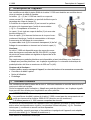
Betriebsanleitung (Original) Betriebsanleitung.................................................. Seite 1 - 12 Operating manual ................................................page 13 - 24 Notice d'utilisation................................................page 25 - 36 Kolben-Strömungswächter Baureihe V 1000 Inhaltsverzeichnis Seite © SiKA • Ba_V1000.pdf 04/2013 . 0 Hinweise zur Betriebsanleitung .................................................................................2 1 Gerätebeschreibung ..................................................................................................3 1.1 Bestimmungsgemäße Verwendung.........................................................................3 2 3 4 5 5.1 5.2 Sicherheitshinweise...................................................................................................4 Bauteile und Funktion................................................................................................6 Werkstofftabelle der benetzten Bauteile ....................................................................6 Einbau und elektrischer Anschluss............................................................................7 Einbau des V 1000 ..................................................................................................7 Elektrischer Anschluss und Schaltpunkt..................................................................8 6 7 8 Wartung und Reinigung ...........................................................................................10 Demontage und Entsorgung....................................................................................10 Technische Daten....................................................................................................11 Bewahren Sie diese Betriebsanleitung zum Nachschlagen auf. Geben Sie diese Betriebsanleitung bei der Veräußerung des Gerätes mit. SiKA Dr.Siebert & Kühn GmbH & Co. KG y Struthweg 7–9 y D-34260 Kaufungen y Germany ℡ +49 5605 803-0 y +49 5605 803-54 y [email protected] y www.SIKA.net Hinweise zur Betriebsanleitung 0 V 1000 Hinweise zur Betriebsanleitung • Die Betriebsanleitung richtet sich an Facharbeiter und angelernte Arbeitskräfte. • Lesen Sie vor jedem Arbeitsschritt die dazugehörigen Hinweise sorgfältig durch und halten Sie die vorgegebene Reihenfolge ein. • Lesen Sie den Abschnitt „Sicherheitshinweise“ besonders aufmerksam durch. Sollten Sie Probleme oder Fragen haben, wenden Sie sich an Ihren Lieferanten oder direkt an: Dr. Siebert & Kühn GmbH & Co. KG Struthweg 7-9 • D - 34260 Kaufungen ℡ 05605-803 0 • 05605-803 54 [email protected] • www.sika.net Verwendete Gefahrenzeichen und Symbole: GEFAHR! Lebensgefahr durch elektrischer Strom! Diese Zeichen kennzeichnet Gefahren, die zu schweren gesundheitlichen Schäden oder zum Tode führen. WARNUNG! / VORSICHT! Verletzungsgefahr! Diese Zeichen kennzeichnet Gefahren, die Personenschäden verursachen, die zu gesundheitlichen Schäden führen oder erheblichen Sachschaden verursachen können. VORSICHT! Materialschaden! Dieses Zeichen weist auf Handlungen hin, die mögliche Sach- und Umweltschäden verursachen können. HINWEIS! BETRIEBSANLEITUNG BEACHTEN! Diese Zeichen gibt Ihnen wichtige Hinweise, Tipps oder Informationen. KEIN HAUSMÜLL! Das Gerät darf nicht zusammen mit Hausmüll entsorgt werden. Beachten und befolgen Sie die damit gekennzeichneten Informationen. ª Befolgen Sie die angegebenen Anweisungen bzw. Handlungsschritte. Halten Sie die Reihenfolge ein. Überprüfen Sie die angegebenen Punkte oder Hinweise. J Verweis auf einen anderen Abschnitt, Dokument oder Quelle. • Gliederungspunkt Urheberschutzvermerk: Weitergabe sowie Vervielfältigung dieser Betriebsanleitung, Verwertung und Mitteilung seines Inhalts sind verboten, soweit nicht ausdrücklich gestattet. Zuwiderhandlungen verpflichten zu Schadenersatz. Alle Rechte für den Fall der Patent-, Gebrauchsmuster- oder Geschmacksmustereintragung vorbehalten. -2- © SiKA • Ba_V1000_de.doc 04/2013 V 1000 1 Gerätebeschreibung Gerätebeschreibung Die SiKA Kolben-Strömungswächter der Baureihe V 1000 sind zur Minimum- bzw. Maximumüberwachung von Flüssigkeitsströmungen vorgesehen. Das Gehäuse (1) +(2) des V 1000 ist mit einem normalen Ventilkörper (3) verschraubt. Der Prozessanschluss erfolgt über das Innengewinde des Ventilkörpers (3). Im Inneren des Gehäusekörpers (2) befindet sich das Kolbensystem und die Aufnahme für die Schalteinheit (J § 3: "Bauteile und Funktion"). Die Abdeckhaube (1) ist mit Hutmuttern (5) am Gehäusekörper (2) des V 1000 verschraubt. Unter der Abdeckhaube (1) sind die Schraubklemmen für den elektrischen Anschluss, die Schalteinheit und die Glimmlampe der Schaltanzeige. Die Kabelverschraubung (6) und der transparente Deckel (4) der Schaltanzeige befinden sich auf der Oberseite der Abdeckhaube (1). Ausführungen: Die Baureihe V 1000 ist mit Ventilkörpern in Nennweiten von DN 08 bis DN 50 lieferbar. Der Schaltpunktbereich ist einstellbar und abhängig von der Nennweite. Ausführungen für Öl sind lieferbar und mit dem Hinweis "Öltauglich" auf dem Typenschild gekennzeichnet. Die kinetischen Viskosität des Öls darf max. 220 mm2/s (cSt) betragen. Lieferumfang: Überprüfen Sie vor Einbau des Gerätes den Lieferumfang und das bestellte Zubehör: • Kolben-Strömungswächter. • Betriebsanleitung. • Verpackung. 1.1 Bestimmungsgemäße Verwendung Die Kolben-Strömungswächter der Baureihe V 1000 sind ausschließlich zur Minimum- bzw. Maximumüberwachung von Flüssigkeitsströmungen vorgesehen. Nur Geräte mit dem Hinweis "Öltauglich" auf dem Typenschild dürfen für den Einsatz im Medium Öl verwendet werden. WARNUNG! Kein Sicherheitsbauteil! Die Kolben-Strömungswächter der Baureihe V 1000 sind keine Sicherheitsbauteile im Sinne der Richtlinie 2006-42-EG (Maschinenrichtlinie). ª Verwenden Sie den V 1000 niemals als Sicherheitsbauteil. Die Betriebssicherheit des gelieferten Gerätes ist nur bei bestimmungsgemäßer Verwendung gewährleistet. Die angegebenen Grenzwerte (J § 8 "Technische Daten") dürfen keinesfalls überschritten werden. Überprüfen Sie vor dem Einbau, ob die benetzten Werkstoffe des Gerätes für das verwendete Medium geeignet sind (J § 4 "Werkstofftabelle"). Technische Änderungen vorbehalten -3- Sicherheitshinweise V 1000 1.1.1 Reedkontakt - Schalten von induktiven oder kapazitiven Lasten VORSICHT! Zerstörung oder Beschädigung des Reedkontaktes! Beachten Sie die max. Kontaktbelastung auf dem Typenschild! Die auf dem Typenschild angegebene max. Kontaktbelastungen (Schaltspannung, Schaltstrom und Schaltleistung) gelten nur für rein ohmsche Lasten und dürfen auf keinem Fall überschritten werden. Insbesondere beim Schalten von induktiven oder kapazitiven Lasten (z. B. Relaisspule, Kondensatoren) können hohe Spannungs- und Stromspitzen auftreten. Selbst eine kurzzeitige Überlastungen kann den Reedkontakt zerstören (Verschweißen der Kontakte) oder beschädigen (reduzierte Lebensdauer). ª Verwenden Sie nur geeignete und geprüfte Schutzmaßnahmen für ihre Anwendung. Schutzmaßnahmen beim elektrischen Anschluss von Reedkontakten: Die folgenden Schutzbeschaltungen sind grundsätzlich möglich: Strombegrenzungswiderstände, RC-Glieder, Freilaufdioden, Suppressordioden, Varistoren oder Kombinationen davon. Überprüfen Sie die Wirksamkeit der ausgewählten Schutzmaßnahme auf den speziellen Lastfall ihrer Anwendung hin. 2 Sicherheitshinweise Bevor Sie den V 1000 installieren, lesen Sie diese Betriebsanleitung sorgfältig durch. Werden die darin enthaltenen Anweisungen, insbesondere die Sicherheitshinweise nicht beachtet, können Gefahren für Mensch, Umwelt, Gerät und Anlage die Folge sein. Die V 1000 entsprechen dem aktuellen Stand der Technik. Dies betrifft die Genauigkeit, die Funktionsweise und den sicheren Betrieb der Geräte. Um eine sichere Bedienung zu gewährleisten, ist sachkundiges und sicherheitsbewusstes Verhalten der Bediener erforderlich. SiKA gewährt persönlich oder durch entsprechende Literatur Hilfestellung für die Anwendung der Produkte. Der Kunde prüft die Einsetzbarkeit des Produktes auf der Basis unserer technischen Informationen. In kunden- und anwendungsspezifischen Tests überprüft der Kunde die Eignung des Produktes für seinen Verwendungszweck. Mit dieser Prüfung gehen Gefahr und Risiko auf unseren Kunden über; unsere Gewährleistung erlischt. Qualifiziertes Personal: Das Personal, das mit der Inbetriebnahme und Bedienung des V 1000 beauftragt wird, muss eine entsprechende Qualifikation aufweisen. Dies kann durch Schulung oder entsprechende Unterweisung geschehen. Dem Personal muss der Inhalt der vorliegenden Betriebsanleitung bekannt und jederzeit zugänglich sein. Der elektrische Anschluss darf nur von einer Elektrofachkraft vorgenommen werden. -4- © SiKA • Ba_V1000_de.doc 04/2013 V 1000 Sicherheitshinweise Allgemeine Sicherheitshinweise: Bei allen Arbeiten sind die bestehenden nationalen Vorschriften zur Unfallverhütung und Sicherheit am Arbeitsplatz einzuhalten. Vorhandene interne Vorschriften des Betreibers sind zu beachten, auch wenn diese nicht in dieser Anleitung genannt werden. Stellen Sie sicher, dass das Medium frei von magnetischen Partikeln ist. Das Einfrieren des Mediums ist durch geeignete Maßnahmen zu verhindern. Soll der Kolben-Strömungswächter später Umgebungstemperaturen < 4 °C ausgesetzt werden, darf zuvor kein Betrieb, z. B. Testbetrieb, mit reinem Wasser erfolgen. Durch im Kolben-Strömungswächter verbliebenes Wasser könnten Frostschäden verursacht werden. Entfernen Sie niemals einen Kolben-Strömungswächter oder Bauteile von ihm aus einer unter Druck stehenden Rohrleitung. Wenn das zu überwachende Medium sehr hohe Temperaturen besitzt, wird auch der Kolben-Strömungswächter bzw. seine Bauteile extrem heiß. Vermeiden Sie Berührungen und stellen Sie keine temperaturempfindlichen Gegenstände in der Nähe ab. Schützen Sie den Kolben-Strömungswächter vor magnetischen Fremdfeldern in der unmittelbaren Umgebung, da diese die Funktionsweise des Gerätes beeinträchtigen können. Schutzart nach DIN EN 60529: Achten Sie darauf, dass die Umgebungsbedingungen am Einsatzort die Anforderungen der angegebenen Schutzart (J § 8 "Technische Daten") nicht überschreiten. Verwenden Sie den V 1000 nur in einwandfreiem Zustand. Beschädigte oder fehlerhafte Geräte müssen sofort überprüft und ggf. ersetzt werden. Verwenden Sie bei Montage, Anschluss und Demontage des V 1000 nur passende Werkzeuge. Typenschilder oder sonstige Hinweise auf dem Gerät dürfen weder entfernt noch unkenntlich gemacht werden, da sonst jegliche Garantie und Herstellerverantwortung erlischt. Spezielle Sicherheitshinweise: Warnhinweise, die sich speziell auf einzelne Funktionsabläufe oder Tätigkeiten beziehen, finden Sie vor den entsprechenden Stellen in dieser Betriebsanleitung. Technische Änderungen vorbehalten -5- Bauteile und Funktion 3 V 1000 Bauteile und Funktion Der Strömungswächter ist auf einem normalen Ventilkörper mit Innengewindeanschluss aufgebaut. Bauteile: (1) Gehäusekörper. (2) Druckfeder. (3) Führungsstange. (4) Magnete. (5) Kolben. (6) Ventilkörper. (7) Flachdichtung. (8) Aufnahme für Schalteinheit. (9) Reedkontakt. (10) O-Ringe. Funktionsprinzip: Der Kolben (5) ist in senkrechter Richtung beweglich und wird vom Führungsstab (3) in der richtigen Position gehalten. Durch die Druckfeder (2) wird der Kolben in den Sitz des Ventilkörpers (6) gedrückt. Bei einsetzender Strömung wird der Kolben (5) aus dem Ventilsitz gehoben. Je stärker die Strömung ist, desto größer wird die Auslenkung des Kolbens (5) und der Magnete (4). Die Magnete (4) verändern ihre Stellung zum Reedkontakt (9). Bei Erreichen des eingestellten Schaltpunktes, werden die Kontakte des Reedschalters (9) umgeschaltet. Bei geringerer Strömung wird die Auslenkung des Kolbens (5) mit den Magneten (4) kleiner. Der Reedkontakt (9) schaltet zurück. 4 Werkstofftabelle der benetzten Bauteile Prüfen Sie vor dem Einbau, ob der Kolben-Strömungswächter werkstoffseitig für das zu überwachende Medium geeignet ist. # Bauteil Material 1 Gehäusekörper Messing (2.0321/2.0402) 2 Druckfeder Edelstahl (1.4310) 3 Führungsstab Messing (2.0402) 4 Magnete Hartferrit 5 Kolben PPN (Hostalen®) 6 Ventilkörper Rotguss RG5 (G-CuSn5ZnPb) 7 Flachdichtung Vulkanfiber 8 Aufnahme für Schalteinheit Messing (2.0321) 10 O-Ringe NBR -6- © SiKA • Ba_V1000_de.doc 04/2013 V 1000 5 Einbau und elektrischer Anschluss Einbau und elektrischer Anschluss Überprüfen Sie vor dem Einbau des V 1000 ob, die Anlage ausgeschaltet ist und sich in einem sicheren und stromlosen Zustand befindet. die Anlage drucklos und abgekühlt ist. GEEIGNETE WERKZEUGE: Verwenden Sie nur geeignete Werkzeuge der passenden Größe. 5.1 Einbau des V 1000 Der Strömungswächter ist selbsttragend und kann direkt in jede Leitung eingebaut werden. Einbauhinweise: • Reinigen Sie zuerst das Rohrleitungssystem, in das der Strömungswächter eingebaut werden soll und befreien Sie es von magnetischen Partikeln wie z. B. Schweißrückständen. • Die bevorzugte Einbaulage ist senkrecht stehend in waagerechte Leitungen. Es ist allerdings möglich, dass das Gehäuse bis max. 70° abweichend von der Senkrechten stehen kann. • In bewegliche Anlagen mit Stoß- und Vibrationsbelastungen darf der Strömungswächter nur senkrecht stehend in waagerechte Rohrleitungen eingebaut werden. • Sorgen Sie dafür, dass in der unmittelbaren Umgebung des Strömungswächters keine magnetischen Fremdfelder die Funktionsweise des Gerätes beeinträchtigen können. • Große ferromagnetische Teile können eine magnetische Beeinflussung des Strömungswächters bewirken, die die Betriebssicherheit gefährdet. Vermeiden Sie deshalb unbedingt die Montage des V 1000 in der Nähe dieser Körper. m ax .7 0° Montage: VORSICHT! Verletzungsgefahr oder Materialschaden! Beachten Sie, dass das Gehäuse werksseitig nur handfest angezogen ist. ª Ziehen Sie das Gehäuse nach erfolgter Montage unbedingt fest. EINBAUMAßE: ª Beachten Sie die Einbaumaße in § 8 "Abmessungen". ª Bauen Sie den Strömungswächter wie ein Ventil in die vorhandene Rohrleitung ein. ª Beachten Sie den Durchflusspfeil am Ventilkörper. Er muss in Strömungsrichtung zeigen! ª Die Abdichtung am Ventilkörper müssen Sie entweder über Gewindeabdichtungen (Teflonband, Oberflächenbeschichtung usw.) oder über Dichtringe, die stirnseitig am Ventilkörper abdichten, realisieren. Technische Änderungen vorbehalten -7- Einbau und elektrischer Anschluss 5.2 V 1000 Elektrischer Anschluss und Schaltpunkt 5.2.1 Abdeckhaube öffnen ª Schrauben Sie die beiden Hutmuttern (SW7) der Abdeckhaube ab. ª Nehmen Sie Unterlegscheiben ab und heben sie die Abdeckhaube nach oben ab. ª Legen Sie die Bauteile für die spätere Verwendung beiseite. 5.2.2 Elektrischer Anschluss GEFAHR! Lebensgefahr durch elektrischer Strom! Schalten Sie die elektrische Anlage spannungsfrei, bevor Sie den V 1000 anschließen. VORSICHT! Zerstörung oder Beschädigung des Reedkontaktes! Die auf dem Typenschild angegebene max. Kontaktbelastungen gelten nur für rein ohmsche Lasten und dürfen auf keinem Fall überschritten werden. ª Beachten Sie § 1.1.1 "Reedkontakt - Schalten von induktiven oder kapazitiven Lasten". Die Strömungswächter der Baureihe V 1000 sind standardmäßig für 230 V AC/DC ausgelegt. Der Strömungswächter darf elektrisch nur in Reihenschaltung mit dem Netz verbunden werden. Er kann in 3 unterschiedlichen Beschaltungen betrieben werden. 2 VAC / VDC 3 schwarz V371 N gelb-grün 82k *1 *2 N 22k, 5W 3 Verbraucher RL1 an Arbeitskontakt 2 N Verbraucher RL1 an Ruhekontakt *3 RL1 3 RL1 2 22k, 5W 3 *2 Arbeitskontakt: Der Verbraucher RL1 wird an Klemme 2 (Arbeitskontakt) angeschlossen. *1 … *3 2 Für die Schaltanzeige muss Klemme 2 entsprechend beschaltet werden (→ *3). braun L V360 Spannung an Klemme 2: Über die Glimmlampe und deren Vorwiderstand liegt auch bei Ruhekontakt eine Spannung an Klemme 2 an. Si (F) blau 1 *1 Ruhekontakt: Der Verbraucher RL1 wird an Klemme 3 (Ruhekontakt) angeschlossen. N kein Verbraucher Rl1 Abb.: Schaltbild *3 Schaltanzeige (kein Verbraucher): Soll die Schaltanzeige ohne Verbraucher RL1 betrieben werden, so muss bei 230 V AC ein Widerstand von 22 kΩ, 5 W an Klemme 2 angeschlossen werden. Bei abweichenden Spannungen entfällt die Schaltanzeige durch die Glimmlampe. Die Glimmlampe der Schaltanzeige leuchtet bei Unterschreitung des eingestellten Schaltpunktes. Vorsicherung: Die Vorsicherung Si ist entsprechend dem Maximalstrom bei der verwendeten Versorgungsspannung zu bemessen und in flinker Ausführung zu verwenden. -8- © SiKA • Ba_V1000_de.doc 04/2013 V 1000 Einbau und elektrischer Anschluss Kabel anschließen: SCHUTZART IP 54: Zur Gewährleistung der Schutzart IP 54 nach EN 60529:2000, muss das verwendete Anschlusskabel einen Manteldurchmesser von 7,5 - 9 mm aufweisen. ª Lösen Sie die beiden Schrauben an der Kabelverschraubung. ª Führen Sie das Anschlusskabel durch die Kabelverschraubung. ª Verbinden Sie die einzelnen Leitungen mit den Schraubklemmen entsprechend der gewünschten Beschaltung (→ Abb.: Schaltbild *1 …*3). ª Ziehen Sie die beiden Schrauben der Kabelverschraubung fest. Wählen Sie die Leitungslänge so, dass die Leitungen zur Schraubklemme nicht unter Zug stehen. Ferner sollte sich die Abdeckhaube problemlos öffnen und schließen lassen. 5.2.3 Einstellen des Schaltpunktes Auf der Schalteinheit befindet sich eine Skala 0 ... 10. Durch Verschieben der Schalteinheit kann der Schaltpunkt eingestellt werden. Dabei entspricht 0 dem minimalem und 10 dem maximalen Wert des Schaltpunktbereiches (→ § 8 "Schaltpunktbereich"). max WICHTIG: Beachten Sie, dass sich die Skala 0 ... 10 nicht linear auf den angegebenen Schaltpunktbereich übertragen lässt. min. Schaltpunkt Arretierungsschraube V1000 linear min 0 10 max. Schaltpunkt Bezugskante ª Lösen Sie die Arretierungsschraube (Innensechskant SW 2,5). ª Verschieben Sie die Schalteinheit auf den gewünschten Schaltpunkt. ª Ziehen Sie die Arretierungsschraube wieder fest. 5.2.4 Abdeckhaube schließen VORSICHT! Materialschaden! Achten Sie darauf, dass der O-Ring beim Schließen der Abdeckhaube nicht beschädigt wird und dass keine Leitungen des Anschlusskabels eingeklemmt werden. ª Setzen Sie die Abdeckhaube passend auf den Gehäusekörper. ª Montieren Sie die Unterlegscheiben und die Hutmuttern auf dem Gewindebolzen. ª Ziehen Sie die Hutmuttern fest. Technische Änderungen vorbehalten -9- Wartung und Reinigung 6 V 1000 Wartung und Reinigung Wartung: Der V 1000 ist wartungsfrei und kann auch nicht vom Anwender repariert werden. Bei einem Defekt muss das Gerät zur Reparatur an den Hersteller zurückgeschickt werden. Reinigung: Reinigen Sie den V 1000 mit einem trockenen oder leicht angefeuchteten, fusselfreien Tuch. Verwenden Sie beim Reinigen keine scharfen Gegenstände oder aggressive Reinigungsmittel. 7 Demontage und Entsorgung VORSICHT! Verletzungsgefahr! Entfernen Sie niemals den V 1000 aus einer im Betrieb befindlichen Anlage. ª Sorgen Sie dafür, dass die Anlage fachgerecht ausgeschaltet wird. Vor der Demontage: Überprüfen Sie vor der Demontage, ob die Anlage ausgeschaltet ist und sich in einem sicheren und stromlosen Zustand befindet. die Anlage drucklos und abgekühlt ist. Demontage: ª Entfernen Sie die elektrischen Anschlüsse. ª Bauen Sie den V 1000 mit passenden Werkzeugen aus. Entsorgung: KEIN HAUSMÜLL! Der V 1000 besteht aus unterschiedlichen Werkstoffen. Er darf nicht zusammen mit Hausmüll entsorgt werden. ª Führen Sie den V 1000 der lokalen Wiederverwertung zu oder ª schicken Sie den V 1000 an Ihren Lieferanten bzw. SiKA zurück. - 10 - © SiKA • Ba_V1000_de.doc 04/2013 V 1000 8 Technische Daten Technische Daten Bei kundenspezifischen Ausführungen können technische Daten gegenüber den Angaben dieser Anleitung abweichen. Bitte beachten Sie die Angaben auf dem Typenschild. Allgemeine und elektrische Daten Allgemeine Kenndaten Elektrische Kenndaten Nenndruck PN 16 Schaltspannung, max. Mediumstemperatur, max. 100 °C Schaltstrom, max. 230 V AC/DC 1A Kontaktbelastung, max. Kenndaten Schaltpunktbereich Toleranz ± 15% Schalthysterese < 10 %* Repr. Schaltgenauigkeit < 2 %* 25 W / 36 VA Schutzart IP 54 * bezogen auf Umschaltpunkt bei fallender Durchflussmenge. Ausführung für den Einsatz im Medium Öl < 220 mm2/s (cSt) Der Schaltpunktbereich ist abhängig vom verwendeten Öl. Die Angaben zum Schaltpunktbereich und Druckverlust der nachfolgenden Tabellen gelten nicht für Öl. Kinetische Viskosität Schaltpunktbereich Schaltpunktbereich und Abmessungen 2…10 2…10 1,0 1,0 V 1015 DN 15 2…13 0,9 V 1020 DN 20 5…28 1,1 V 1025 DN 25 20…110 1,3 V 1032 DN 32 23…140 1,7 V 1040 DN 40 50…220 2,2 V 1050 DN 50 130…400 3,3 * bezogen auf Umschaltpunkt bei fallender Durchflussmenge. Anschlussh3 gewinde D V 1008 27/22** 50 V 1010 27/22** 50 10 11 81 81 26 110 102 26 110 102 G¼ G⅜ V 1015 27 50 11 67 30 110 102 G½ V 1020 33 50 14 80 33 110 102 G¾ V 1025 41 50 17 95 40 110 102 G1 V 1032 52 60 14 98 40 110 102 G1¼ V 1040 58 70 17 130 45 99 91 SW1 G1½ V 1050 72 90 20 137 51 99 91 G2 ** Schlüsselweiten der mitgelieferten Reduzierungen. Technische Änderungen vorbehalten SW2 h1 SW1 Abmessungen [mm] SW2 l1 l2 h1 h2 D Typ ø 50 h2 V 1008 DN 08 V 1010 DN 10 M20 x 1,5 h3 Gewicht [kg] Nennweite ~ 50 Schaltpunktbereich* H2O, 20°C, [l/min] Typ l1 l2 - 11 - Technische Daten V 1000 Druckverlustkurven - 12 - © SiKA • Ba_V1000_de.doc 04/2013 Operating manual (Translation) Betriebsanleitung.................................................. Seite 1 - 12 Operating manual ................................................page 13 - 24 Notice d'utilisation................................................page 25 - 36 Piston Flow Monitor Series V 1000 Table of contents page © SiKA • Ba_V1000.pdf 04/2013 . 0 About this operating manual ....................................................................................14 1 Device description ...................................................................................................15 1.1 Intended use..........................................................................................................15 2 3 4 5 5.1 5.2 Safety instructions ...................................................................................................16 Components and function........................................................................................18 Materials table of wetted components .....................................................................18 Installation and electrical connection .......................................................................19 Installation of the V 1000 .......................................................................................19 Electrical connection and switch point ...................................................................20 6 7 8 Maintenance and cleaning.......................................................................................22 Disassembly and disposal .......................................................................................22 Technical data .........................................................................................................23 Please keep this operating manual for future reference. If the device is resold, please provide the operating manual along with it. SiKA Dr.Siebert & Kühn GmbH & Co. KG y Struthweg 7–9 y D-34260 Kaufungen y Germany ℡ +49 5605 803-0 y +49 5605 803-54 y [email protected] y www.SIKA.net About this operating manual 0 V 1000 About this operating manual • The operating manual is aimed at specialists and semi-skilled personnel. • Before each step, read through the relevant advice carefully and keep to the specified order. • Thoroughly read and understand the information in the section “Safety instructions”. If you have any problems or questions, please contact your supplier or contact us directly at: Dr. Siebert & Kühn GmbH & Co. KG Struthweg 7-9 • D - 34260 Kaufungen ℡ 05605-803 0 • 05605-803 54 [email protected] • www.sika.net Hazard signs and other symbols used: DANGER! Risk of death due to electric current! This sign indicates dangers which could lead to serious health defects or to death. WARNING! / CAUTION! Risk of injury! This sign indicates dangers that cause personal injuries that can lead to health defects or cause considerable damage to property. CAUTION! Material damage! This sign indicates actions which could lead to possible damage to material or environmental damage. NOTICE! ADHERE TO OPERATING MANUAL! This symbol indicates important notices, tips or information. NO DOMESTIC WASTE! The device must not be disposed of together with domestic waste. Pay attention to and comply with information that is marked with this symbol. ª Follow the specified instructions and steps. Adhere to the given order. Check the specified points or notices. J Reference to another section, document or source. • Item Copyright notice: The reproduction, distribution and utilization of this operating manual as well as the communication of its contents to others without express authorization is prohibited. Offenders will be held liable for the payment of damages. All rights reserved in the event of the grant of a patent, utility model or design. - 14 - © SiKA • Ba_V1000_en.doc 04/2013 V 1000 1 Device description Device description The SiKA piston flow monitor of the V 1000 series are designed for minimum or maximum monitoring of liquid flows. The housing (1) +(2) of the V 1000 is fitted on a normal valve body (3). The device is connected to the process system by the female threaded ports of the valve body (3). The piston system and the holder for the switching unit are located inside the housing body (2) (J § 3: "Components and function"). The housing cover (1) is screwed to the housing body (2) of the V 1000 by acorn nuts (5). The screw terminals for the electrical connection, the switching unit and the switch indicator glow lamp are located under the housing cover (1). The cable gland (6) and the transparent lens (4) of the switch indicator are located on top of the housing cover (1). Version: The V 1000 series is available with valve bodies having nominal diameters DN 08 to DN 50. The switching point range is adjustable and depends on the nominal diameter. Versions for use with oil are available and are marked "Oil compatible" on the type plate. The maximum allowable kinetic viscosity of the oil is 220 mm2/s (cSt). Scope of delivery: Before installing the device, check the delivered items and ordered accessories: • Piston flow monitor. • Operating manual. • Packaging. 1.1 Intended use The piston flow monitor of the V 1000 series are designed for minimum or maximum monitoring of liquid flows. Only devices marked "Oil compatible" on the type plate may be used to monitor oil. WARNING! No safety component! The piston flow monitor of the V 1000 series are not safety components in accordance with Directive 2006-42-EG (Machine Directive). ª Never use the V 1000 as a safety component. The operational safety of the device supplied is only guaranteed by intended use. The specified limits (J § 8: "Technical data") may under no circumstances be exceeded. Before installing the device, check that the wetted materials of the device are compatible with the media being used (§ 4 "Materials table"). Technical changes reserved - 15 - Safety instructions V 1000 1.1.1 Reed contakt - Switching of inductive or capacitive loads CAUTION! Destruction or damage of reed contact! Take notice of the max. contact loads mentioned on the specification plate! The max. contact loads mentioned on the type plate (switching voltage, switching current and switching capacity) refer to pure ohmic loads and may not be exceeded under any circumstances. High voltage and current peaks can occur, particularly when switching inductive or capacitive loads (e.g. relay coil, capacitors). Even if the overload is brief, this can destroy (welding the contacts) or damage (reduced lifespan) the reed contact. ª Only use protection methods which be appropriate and checked. Protection method when electrical connection of reed contacts: The following protective circuits are basically possible: current limiting resistors, RC circuits, freewheeling diodes, suppression diodes, varistors or a combination of these. Please verify the effectiveness of the chosen protection method in accordance with the specific loads involved. 2 Safety instructions Before you install the V 1000, read through this operating manual carefully. If the instructions contained within it are not followed, in particular the safety guidelines, this could result in danger for people, the environment, and the device and the system it is connected to. The V 1000 correspond to the state-of-the-art technology. This concerns the accuracy, the operating mode and the safe operation of the device. In order to guarantee that the device operates safely, the operator must act competently and be conscious of safety issues. SiKA provides support for the use of its products either personally or via relevant literature. The customer verifies that our product is fit for purpose based on our technical information. The customer performs customer- and application-specific tests to ensure that the product is suitable for the intended use. With this verification all hazards and risks are transferred to our customers; our warranty is not valid. Qualified personnel: The personnel who are charged for the installation, operation and maintenance of the V 1000 must hold a relevant qualification. This can be based on training or relevant tuition. The personnel must be aware of this operating manual and have access to it at all times. The electrical connection should only be carried out by a fully qualified electrician. - 16 - © SiKA • Ba_V1000_en.doc 04/2013 V 1000 Safety instructions General safety instructions: In all work, the existing national regulations for accident prevention and safety in the workplace must be complied with. Any internal regulations of the operator must also be complied with, even if these are not mentioned in this manual. Ensure that the medium is free from magnetic particles. Suitable measures should be taken to prevent the medium from freezing. If the piston flow monitor is to be used in ambient temperatures of <4 °C, do not carry out any operation beforehand with pure water, e.g. a test run. Residual water in the flow monitor can result in frost damage. Never remove a piston flow monitor or any of its components from a pipe under pressure. If the medium which is to be monitored is very hot, the piston flow monitor or their components will also become very hot. In this case, neither touch the flow monitor nor place any heat-sensitive objects in its vicinity. Protect the piston flow monitor against external magnetic fields in the immediate vicinity, since these can impair device functioning. Degree of protection according to EN 60529: Ensure that the ambient conditions at the site of use does not exceed the requirements for the stated protection rating (J § 8: "Technical data"). Only use the V 1000 if it is in perfect condition. Damaged or faulty devices must be checked without delay and, if necessary, replaced. When fitting, connecting and removing the V 1000 use only suitable appropriate tools. It is prohibited to remove or make type plates or any other information attached to the equipment indecipherable, otherwise all warranties and the responsibility of the manufacturer no longer apply. Special safety instructions: Warnings that are specifically relevant to individual operating procedures or activities can be found at the beginning of the relevant sections of this operating manual. Technical changes reserved - 17 - Components and function 3 V 1000 Components and function The flow monitor is fitted on a normal valve body with a female threaded connection. Components: (1) Housing body. (2) Compression spring. (3) Guide rod. (4) Magnets. (5) Piston. (6) Valve body. (7) Flat gasket. (8) Holder for switching unit. (9) Reed contact. (10) O-rings. Functional principle: The piston (5) is free to move vertically and is held in the correct position by the guide rod (3). The piston is pressed against the valve seat in the valve body (6) by the compression spring (2). With incoming flow, the piston (5) is lifted free from the valve seat. The stronger the flow, the more the piston (5) and magnets (4) are displaced. The magnets (4) move relative to the reed contact (9). When the set switching point is reached, the contacts of the reed switch (9) switch over. When the flow rate drops, the displacement of the piston (5) and magnets (4) is less. The reed contact (9) switches back. 4 Materials table of wetted components Before installation, check whether the material of the piston flow monitor is suitable for the medium to be monitored. # Component Material 1 Housing body Brass (2.0321/2.0402) 2 Compression spring Stainless steel (1.4310) 3 Guide rod Brass (2.0402) 4 Magnets Hard ferrite 5 Piston PPN (Hostalen®) 6 Valve body Red brass RG5 (G-CuSn5ZnPb) 7 Flat gasket Vulcanized floer 8 Holder for switching unit Brass (2.0321) 10 O-rings NBR - 18 - © SiKA • Ba_V1000_en.doc 04/2013 V 1000 5 Installation and electrical connection Installation and electrical connection Before installing the V 1000, check that the equipment is switched off and is in a safe and de-energised state. the equipment is depressurised and has coolde down. SUITABLE TOOLS: ª Use only suitable tools of the correct size. 5.1 Installation of the V 1000 The flow monitor is self-supporting and can therefore be fitted in any pipeline. Installation instructions: • Firstly, clean the pipe system in which the flow monitor is to be installed and remove any magnetic particles, e.g. welding residue. • The preferred installation position is upright vertical in horizontal pipelines. However, it is also possible for the upper part to deviate from the vertical by up to 70° • In movable systems subjected to impact or vibration stresses, the flow monitor should only be installed vertically in horizontal pipelines. • Please make sure that there are no external magnetic fields in the immediate vicinity of the flow monitor, since these can impair device functioning • Large ferromagnetic parts can effect the magnetic action of the flow monitor and endanger operational safety. For this reason, never install the V 1000 near such parts. m ax .7 0° Assembly: CAUTION! Risk of injury or material damage! Pay attention that the housing is only hand-tightened at the works. ª Always tighten the housing after installation. MOUNTING DIMENSIONS: ª Pay attention to the mounting dimensions in § 8 "Dimensions". ª Fit the flow monitor in the existing pipe in the same way as a valve. ª Pay attention to the flow arrow on the valve body. It must point in the same direction as the flow! ª The sealing on the valve body has to be carried out with either thread sealants (Teflon tape, surface coating, etc.) or via sealing rings on the face of the tube section. Technical changes reserved - 19 - Installation and electrical connection 5.2 V 1000 Electrical connection and switch point 5.2.1 Open the cover ª Unscrew the two acorn nuts (a/f 7) from the housing cover. ª Remove the washers and lift up the cover. ª Place these parts aside for later use. 5.2.2 Electrical connection DANGER! Risk of death due to electric current! Always de-energize the system before connecting the V 1000. CAUTION! Destruction or damage of reed contact! The max. contact loads mentioned on the type plate refer to pure ohmic loads and may not be exceeded under any circumstances. ª Pay attention to § 1.1.1 "Reed contakt - Switching of inductive or capacitive loads". The flow monitor of the V 1000 series are designed as standard for 230 V AC/DC. The flow monitor must always be connected in a series circuit with the AC/DC mains. It can be used with three different wiring schemes. 2 VAC / VDC 3 black V371 N yellow-green 82k *1 *2 Load RL1 on n.o. contact N 22k, 5W 3 N 2 Load RL1 on n.c. contact *3 RL1 3 RL1 2 22k, 5W 3 *2 Normally open contact: The load RL1 is connected to terminal 2 (Normally open contact). L *1 … *3 2 For switch indication, terminal 2 must be wired appropriately (→ *3). brown V360 Voltage on terminal 2: A voltage is present on terminal 2, even when the contact is in the normal position, due to the glow lamp and its series resistor. Si (F) blue 1 *1 Normally closed contact: The load RL1 is connected to terminal 3 (Normally closed contact). N no load Rl1 Fig.: Wiring diagram *3 Switch indicator (no load): If it is desired to use the switch indicator without a load RL1, a 22 kΩ, 5 W resistor must be connected to terminal 2 with a supply voltage of 230 V AC. At other voltages, the glow lamp cannot be used for switch indication. The switch indicator glow lamp lights up when the flow is below the set switching point Back-up fuse: The back-up fuse Si must be rated in accordance with the maximum current for the supply voltage used and must be quick-acting. - 20 - © SiKA • Ba_V1000_en.doc 04/2013 V 1000 Installation and electrical connection Connecting the cable: DEGREE OF PROTECTION IP 54: To guarantee the degree of protection IP 54 according to EN 60529:2000, the applied connecting cable has to have a sheathing diameter of between 7,5 - 9 mm. ª Loosen the two screws of the cable gland. ª Feed the connecting cable through the cable gland. ª Connect the individual leads to the screw terminals according to the desired wiring scheme (→ Fig.: Wiring diagram *1 – *3). ª Tighten the two screws of the cable gland. Ensure that the leads connected to the screw terminal are long enough to avoid putting them under strain. Also check that the cover can be removed and replaced easily. 5.2.3 Set switching point A scale ranging from 0 to 10 is fitted to the switching unit. The switching point can be set by sliding the switching unit. Here 0 corresponds to the minimum of the switching point range and 10 to the maximum. (→ § 8 "Switching point range"). IMPORTANT: Please note that the switching point setting does not have a linear relationship to the scale graduations. min. Switching point max V1000 linear min 0 10 max. Switching point Locking screw Reference mark ª Loosen the locking screw (hexagon socket a/f 2.5). ª Slide the switching unit to the desired switching point. ª Retighten the locking screw. 5.2.4 Close the cover CAUTION! Material damage! When closing the cover, be careful to avoid damaging the O-ring and ensure that the leads of the connecting cable are not trapped. ª Fit the cover on the housing body. ª Fit the washers and acorn nuts on the threaded studs. ª Tighten the acorn nuts. Technical changes reserved - 21 - Maintenance and cleaning 6 V 1000 Maintenance and cleaning Maintenance: The V 1000 is maintenance-free and cannot be repaired by the user. In case of a defect, the device must be returned back to the manufacturer for repair. Cleaning: Clean the V 1000 with a dry or slightly damp lint-free cloth. Do not use sharp objects or aggressive agents for cleaning. 7 Disassembly and disposal CAUTION! Risk of injury! Never remove the V 1000 from a plant in operation. ª Make sure that the plant is shut down professionally. Before disassembly: Prior to disassembly, ensure that the equipment is switched off and is in a safe and de-energised state. the equipment is depressurised and has cooled down. Disassembly: ª Remove the electrical connectors. ª Remove the V 1000 using suitable tools. Disposal: NO HOUSEHOLD WASTE! The V 1000 consists of various different materials. He must not be disposed of with household waste. ª Take the V 1000 to your local recycling plant or ª send the V 1000 back to your supplier or to SiKA. - 22 - © SiKA • Ba_V1000_en.doc 04/2013 V 1000 8 Technical data Technical data The technical data of customised versions may differ from the data in these instructions. Please observe the informations specified on the type plate. General and electrical data General characteristics Electrical characteristics Nominal pressure PN 16 Switching voltage, max. 230 V AC/DC Medium temperature, max. 100 °C Switching current, max. 1A Characteristics switching point range Contact loads, max. 25 W / 36 VA Tolerance Degree of protection IP 54 ± 15% Switching hysteresis < 10 %* Rep. switching accuracy < 2 %* * referred to switchover point for falling flow rate. Version for use with oil < 220 mm2/s (cSt) The switching point range depends on the oil that is used. The switching point range and pressure drop data in the following tables does not apply to oil. Kinetic viscosity Switching point range Switching point range and dimensions V 1008 V 1010 DN 08 DN 10 2…10 2…10 1.0 1.0 V 1015 DN 15 2…13 0.9 V 1020 DN 20 5…28 1.1 V 1025 DN 25 20…110 1.3 V 1032 DN 32 23…140 1.7 V 1040 DN 40 50…220 2.2 V 1050 DN 50 130…400 * referred to switchover point for falling flow rate. ø 50 Thread h3 connection D V 1008 27/22** 50 V 1010 27/22** 50 10 11 81 81 26 110 102 26 110 102 G¼ G⅜ V 1015 27 50 11 67 30 110 102 G½ V 1020 33 50 14 80 33 110 102 G¾ V 1025 41 50 17 95 40 110 102 G1 V 1032 52 60 14 98 40 110 102 G1¼ V 1040 58 70 17 130 45 99 91 V 1050 72 90 20 137 51 99 91 ** Width a/f of the included reducing fittings. Technical changes reserved SW2 h1 SW1 Dimensions [mm] SW2 l1 l2 h1 h2 3.3 D Type M20 x 1,5 h2 Weight [kg] h3 Switching point range * H2O, 20°C, [l/min] ~ 50 Nominal diameter Type SW1 G1½ G2 l1 l2 - 23 - Technical data V 1000 Pressure drop curves - 24 - © SiKA • Ba_V1000_en.doc 04/2013 Notice d'utilisation (Traduction) Betriebsanleitung.................................................. Seite 1 - 12 Operating manual ................................................page 13 - 24 Notice d'utilisation................................................page 25 - 36 Contrôleur de débit à piston Séries V 1000 Sommaire page © SiKA • Ba_V1000.pdf 04/2013 . 0 Indications sur la notice d'utilisation.........................................................................26 1 Description de l'appareil ..........................................................................................27 1.1 Utilisation conforme ...............................................................................................27 2 3 4 5 5.1 5.2 Consignes de sécurité .............................................................................................28 Composants et fonction ...........................................................................................30 Tableau de matériaux des composants mouillés.....................................................30 Installation et branchement électrique .....................................................................31 Montage du V 1000 ...............................................................................................31 Branchement électrique et point de commutation .................................................32 6 7 8 Entretien et Nettoyage.............................................................................................34 Démontage et Élimination .......................................................................................34 Données techniques................................................................................................35 Conservez cette notice d'utilisation pour vous y reporter. Joignez cette notice d'utilisation à la vente de l'appareil. SiKA Dr.Siebert & Kühn GmbH & Co. KG y Struthweg 7–9 y D-34260 Kaufungen y Germany ℡ +49 5605 803-0 y +49 5605 803-54 y [email protected] y www.SIKA.net Indications sur la notice d'utilisation 0 V 1000 Indications sur la notice d'utilisation • La notice d'utilisation est destinée à un personnel formé et spécialisé. • Avant chaque étape de travail, lisez attentivement les indications correspondantes dans l'ordre indiqué. • Lisez particulièrement attentivement le chapitre « Instructions de sécurité ». Si vous avez des problèmes ou des questions, adressez-vous à votre fournisseur ou directement à : Dr. Siebert & Kühn GmbH & Co. KG Struthweg 7-9 • D - 34260 Kaufungen ℡ 05605-803 0 • 05605-803 54 [email protected] • www.sika.net Signes et symboles de sécurité utilisés : DANGER ! Danger de mort par électrocution ! Ce signe indique un danger susceptible d'entraîner de graves blessures ou même la mort. AVERTISSEMENT ! / ATTENTION ! Risque de blessure ! Ce signe indique un danger susceptible d'entraîner des blessures corporelles, des dommages personnels ou des dégâts matériels considérables. ATTENTION ! Dégâts matériels ! Ce signe indique des manipulations qui peuvent provoquer des dégâts matériels et à l'environnement. INDICATION ! SUIVEZ LA NOTICE D'UTILISATION ! Ce symbole indique des indications, astuces ou informations importants. PAS DE DECHET MENAGER ! Ne jetez pas cet dispositif avec les déchets ménagers. Prenez note et suivez attentivement les informations qu'il contient. ª Suivez les instructions et étapes de manipulation. Données dans l'ordre. Vérifiez les points ou indications donnés. J Renvoi à un autre chapitre, document ou source. • Point d'énumération. Note sur la protection des droits d'auteur : Toute communication ou reproduction de ce notice d'utilisation, toute exploitation ou communication de son contenu sont interdites, sauf autorisation expresse. Tout manquement à cette règle est illicite et expose son auteur au versement de dommages et intérêts. Tous droits réservés pour le cas de la délivrance d'un brevet, d'un modèle d'utilité ou d'un modèle de présentation. - 26 - © SiKA • Ba_V1000_fr.doc 04/2013 V 1000 1 Description de l'appareil Description de l'appareil Les contrôleurs de débit à piston SiKA de la série V 1000 sont destinés au contrôle des minima et maxima du débit de liquides. Le boîtier (1) + (2) du V 1000 est vissé à un corps de vanne normal (3). L'adaptation au procédé s'effectue par le taraudage du corps de vanne (3). À l'intérieur du corps de boîtier (2) se trouvent le système de piston et le logement pour l'unité de commutation (J § 3: « Composants et fonction »). Le capot (1) est vissé au corps de boîtier (2) du avec des boulons borgnes (5). Sous le capot (1) se trouvent les bornes à vis pour le raccordement électrique, l'unité de commutation et la lampe fluorescente de l'affichage du commutateur. Le passe-câble à vis (6) et le couvercle transparent (4) de l'affichage du commutateur se trouvent sur le haut du capot (1). Versions : La série V 1000 est disponible avec des corps de vanne dans des largeurs nominales de DN 08 à DN 50. La plage de points de commutation est réglable et dépend de la largeur nominale. Des versions pour produits pétroliers sont disponibles et sont identifiées avec l'indication « Adapté aux produits pétroliers » sur la plaque signalétique. La viscosité cinématique du produit pétrolier doit être au maximum de 220 mm2/s (cSt). Contenu de la livraison : Veuillez contrôler, avant le montage de l'appareil, le volume de livraison et les accessoires commandés : • Contrôleur de débit à piston. • Notice d'utilisation. • Emballage. 1.1 Utilisation conforme Les contrôleurs de débit à piston de la série V 1000 sont destinés au contrôle des minima et maxima du débit de liquides. Seuls les appareils avec l'indication « Adapté aux produits pétroliers » sur la plaque signalétique peuvent être utilisés pour l'exploitation en milieu pétrolier. AVERTISSEMENT ! Aucun composant de sécurité ! Les contrôleurs de débit à piston de la série V 1000 ne sont pas des composants de sécurité aux termes de la directive 2006-42-CE (directive sur les machines). ª N'utilisez jamais un V 1000 comme composant de sécurité. La sécurité du fonctionnement de l'appareil fourni n'est garantie que dans le cadre d'une utilisation selon les dispositions en vigueur. Les données limites indiquées (J § 8 « Données techniques ») ne doivent en aucun cas être dépassées. Veuillez contrôler, avant le montage, si les matériaux imprégnés de l'appareil sont adaptés pour le fluide utilisé (§ 4 « Tableau de matériaux »). Sous réserve de modifications techniques - 27 - Consignes de sécurité V 1000 1.1.1 Contact reed - Commuter de charges inductives ou capacitaires ATTENTION ! Destruction ou endommagement du contact reed ! Veuillez respecter la charge max. des contacts, indiquée sur la plaque signalétique ! Les charges max. (tensions de commutation, courant de commutation et puissance de rupture), qui sont indiquées sur la plaque signalétique, sont uniquement valables pour des charges purement ohmiques et ne doivent en aucun cas être dépassées. Des pics de tension et de courant élevés surviennent surtout lors de la commutation de charges inductives ou capacitives (par exemple bobine, condensateurs). Même des surcharges de courte durée peuvent détruire le contact reed (soudure des contacts) ou l'endommager (durée d'utilisation réduite). ª Pour votre application, utilisez uniquement des mesures de sécurité adaptées et contrôlées. Mesure de protection de le branchement électrique de contacts reed : Les circuits de protection suivants sont généralement possibles : résistances de limitation de courant, circuits RC, diodes de roue libre, diodes de suppression, varistors ou des combinaisons de ces éléments. Contrôlez l'efficacité de la mesure de sécurité choisie pour le cas spécifique de la charge de votre application. 2 Consignes de sécurité Avant d'installer V 1000, lisez attentivement ce notice d'utilisation. Si les instructions qui y sont contenues, en particulier les instructions de sécurité, ne sont pas respectées, cela peut entraîner des dangers pour les personnes, pour l'environnement, l'appareil et le système. Les V 1000 correspondent à l'état actuel de la technique. Cela concerne l'exactitude, le mode de fonctionnement et la sécurité du fonctionnement de l'appareil. Pour garantir un fonctionnement sûr, un comportement professionnel et axé sur la sécurité est nécessaire de la part de l'utilisateur. SiKA garantit personnellement ou via une littérature correspondante une assistance à l'utilisation des produits. Le client vérifie l'utilisabilité du produit sur la base de nos informations techniques. Dans les tests spécifiques au client et d'utilisation, le client contrôle la qualification du produit pour son emploi prévu. Avec ce contrôle, risque et danger sont transmis à nos clients : notre garantie prend fin. Personnel qualifié : Le personnel chargé du montage, de l'utilisation et de la maintenance de V 1000 doit avoir reçu une qualification adéquate. Cela peut se faire par une formation scolaire ou continue correspondante. Le contenu de cette présente notice d'utilisation doit être connu du personnel et lui être accessible à tout moment. Seul un électricien est autorisé à effectuer le branchement électrique. - 28 - © SiKA • Ba_V1000_fr.doc 04/2013 V 1000 Consignes de sécurité Instructions générales de sécurité : Pour tout travail, les prescriptions nationales en vigueur de sécurité et de prévention des accidents doivent être respectées sur le lieu de travail. Les prescriptions internes existantes de l'exploitant doivent être prises en considération même si elles ne sont pas spécifiées dans ce document. S’assurer que le milieu est exempt de particules magnétiques. Prévenir le gel du milieu avec des mesures adéquates. Si le contrôleur de débit à piston doit être soumis plus tard à des températures environnantes <4 °C, il ne faut pas l’opérer en premier lieu, pour un test par ex., avec de l’eau pure. L’eau résiduelle dans le commutateur de débit pourrait entraîner des dégâts dus au gel. Si l’installation se trouve sous pression, il ne faut en aucun cas démonter le contrôleur de débit à piston ou sa composants. Si le milieu à contrôler présente une température très élevée, le contrôleur de débit à piston et leurs composants deviennent aussi très chauds. Evitez tout contact et éloignez les objets sensibles aux températures élevées. Protégez le contrôleur de débit à piston des champs magnétiques externes de l’environnement proche car ils peuvent altérer le fonctionnement de l'appareil. Degré de protection selon DIN EN 60529 : Veillez à ce que les conditions environnementales sur le lieu d'utilisation ne dépassent pas les prescriptions du type de protection donné (J § 8 « Données techniques »). Utilisez le V 1000 uniquement à l'état intact. Les appareils endommagés ou défectueux doivent être immédiatement vérifiés et, le cas échéant, remplacés. Utilisez uniquement des outils adaptés pour le montage, le branchement et le démontage du V 1000. Les plaques signalétiques ou autres indications sur l'appareil ne doivent être ni enlevées ni rendues illisibles, sinon la garantie et la responsabilité du fabricant expirent. Instructions spéciales de sécurité : Vous trouverez des avertissements qui se rapportent spécialement à chaque procédure ou activité aux endroits correspondants dans ce notice d'utilisation. Sous réserve de modifications techniques - 29 - Composants et fonction 3 V 1000 Composants et fonction Le contrôleur de débit est monté à un corps de soupage normal avec un raccord taraudé. Composants : (1) Corps de boîtier. (2) Ressort de pression. (3) Barre de guidage. (4) Aimants. (5) Piston. (6) Corps de vanne. (7) Joint plat. (8) Logement pour unité de commutation. (9) Contact reed. (10) Joints torique. Principe de fonctionnement : Le piston (5) est mobile verticalement et est maintenu dans la bonne position par la barre de guidage (3). Par le ressort de pression (2), le piston est pressé dans le siège du corps de vanne (6). Lorsqu'il y a du débit, le piston (5) est soulevé hors du siège de vanne. Plus le débit est fort, plus grand est le déplacement du piston (5) et des aimants (4). Les aimants (4) changent de position par rapport au contact Reed (9). Lorsque le point de commutation réglé est atteint, les contacts du commutateur Reed (9) commutent. Lorsque le débit est plus faible, le déplacement du piston (5) avec les aimants (4) diminue. Le contact Reed (9) revient en position initiale. 4 Tableau de matériaux des composants mouillés Avant le montage, assurez-vous que les matériaux composant le contrôleur de débit à piston soient adaptés au milieu à surveiller. # Composant Matériau 1 Corps de boîtier Laiton (2.0321/2.0402) 2 Ressort de pression Acier spécial (1.4310) 3 Barre de guidage Laiton (2.0402) 4 Aimants Ferrite céramique 5 Piston PPN (Hostalen®) 6 Corps de vanne Laiton rouge (G-CuSn5ZnPb) 7 Joint plat Fibre vulcanisée 8 Logement pour unité de commutation Laiton (2.0321) 10 Joints torique - 30 - NBR © SiKA • Ba_V1000_fr.doc 04/2013 V 1000 5 Installation et branchement électrique Installation et branchement électrique Avant la pose du V 1000, vérifiez que : l'installation a été mise hors service et qu'elle est sécurisée et sans alimentation électrique ; l'installation est dépressurisée et refroidie. OUTILS APPROPRIES : ª N'utilisez que des outils appropriés de la taille adaptée. 5.1 Montage du V 1000 Le contrôleur de débit est autoportant et il peut être installé directement dans n'importe quelle conduite. Instructions de montage : • Nettoyer tout d’abord la tuyauterie dans laquelle le contrôleur de débit doit être monté et débarrassez-la des particules aimantées comme par ex. des résidus de soudage. • La position de montage privilégiée est à la verticale dans des conduites horizontales. Il est toutefois possible de positionner le boîtier jusqu'à un maximum de 70° d'écart par rapport à la verticale. • Dans des installations mobiles avec des expositions aux chocs et aux vibrations, le contrôleur de débit doit être monté uniquement en position verticale dans des canalisations horizontales. • Veillez à ce qu'aucun champ magnétique étranger dans l'environnement immédiat du contrôleur de débit ne puisse altérer le fonctionnement de l'appareil. • Les grosses pièces ferromagnétiques peuvent avoir sur le contrôleur de débit un impact magnétique qui porte atteinte à la sécurité de fonctionnement. Évitez donc absolument le montage du V 1000 à proximité de ces éléments. m ax .7 0° Montage : ATTENTION ! Risque de blessure ou dégâts matériels ! Notez que, départ usine, le boîtier n'est serré qu'à la main. ª Serrez le boîtier impérativement une fois le montage effectué. COTES DE MONTAGE : ª Respectez les cotes de montage dans le § 8 « Dimensions ». ª Montez le contrôleur de débit comme une vanne dans la canalisation existante. ª Respectez la flèche de débit sur le corps de vanne. Elle doit indiquer le sens de l'écoulement ! ª Vous devez réaliser l'étanchéité du corps de vanne soit par des dispositifs d'étanchéité de filetage (bande téflon, revêtements de surface etc.), soit par des bagues d'étanchéité qui assurent une étanchéité frontale du corps de vanne. Sous réserve de modifications techniques - 31 - Installation et branchement électrique 5.2 V 1000 Branchement électrique et point de commutation 5.2.1 Ouvrir le capot ª Dévissez les deux boulons borgnes (clé de 7) du capot. ª Ôtez les rondelles et retirez le couvercle par le haut. ª Mettez les éléments de côté pour l'utilisation ultérieure. 5.2.2 Branchement électrique DANGER ! Danger de mort par électrocution ! Mettez l'installation hors tension avant de brancher le V 1000. ATTENTION ! Destruction ou endommagement du contact reed ! Les charges max., qui sont indiquées sur la plaque signalétique, sont uniquement valables pour des charges purement ohmiques et ne doivent en aucun cas être dépassées. ª Prenez note § 1.1.1 « Contact reed - Commuter de charges inductives ou capacitaires ». Les contrôleurs de débit de la série V 1000 sont dimensionnés pour du 230 V AC/DC en standard. Le contrôleur de débit doit être relié électriquement au réseau uniquement par montage en série. Il peut fonctionner dans 3 dispositions différentes. 2 VAC / VDC 3 noir V371 N jaune-vert 82k *1 *2 N 22k, 5W 3 Récepteur RL1 à le contact de travail 2 N Récepteur RLL1 à le contact de repos *3 RL1 3 RL1 2 22k, 5W 3 *2 Contact de travail : Le récepteur RL1 est connecté à la borne 2 (contact de travail). L *1 … *3 2 Pour l'affichage du commutateur, la borne 2 doit être connectée en conséquence (→ *3). marron V360 Tension à la borne 2 : Par la lampe à incandescence et sa résistance de série, il y a une tension à la borne 2 même avec le contact de repos. Si (F) bleu 1 *1 Contact de repos : Le récepteur RL1 est connecté à la borne 3 (contact de repos). N pas de récepteur Rl1 Fig. : schéma électrique *3 Affichage du commutateur (pas de récepteur) : Si l'affichage du commutateur doit fonctionner sans récepteur RL1, alors une résistance de 22 kΩ, 5 W en 230 V AC doit être connectée à la borne 2. Pour des tensions différentes, l'affichage du commutateur par la lampe à incandescence est supprimé. La lampe à incandescence de l'affichage du commutateur s'allume tant que le point de commutation réglé n'est pas atteint. Fusible amont : Le fusible amont Si est dimensionné en fonction du courant maximum à la tension d'alimentation utilisée et doit être utilisé en version rapide. - 32 - © SiKA • Ba_V1000_fr.doc 04/2013 V 1000 Installation et branchement électrique Brancher le câble : DEGRÉ DE PROTECTION IP 54: Afin de garantir l' indice de protection IP 54 selon EN 60529:2000, le diamètre externe de la gaine du câble de connexion utilisé doit être compris entre 7,5 et 9 mm. ª Desserrez les deux vis sur le passe-câble à vis. ª Passez le câblage de connexion à travers le passe-câble à vis. ª Reliez les différents câbles aux bornes à vis selon la disposition souhaitée (→ Fig. : schéma électrique *1…*3). ª Serrez les deux vis du passe-câble à vis. Choisissez une longueur de câble telle que les câbles branchés sur les bornes à vis ne soient pas tendus. De plus, le capot doit pouvoir s'ouvrir et se fermer sans problème. 5.2.3 Réglage du point de commutation Sur l'unité de commutation se trouve une échelle graduée 0...10. Le point de commutation peut être réglé en déplaçant l'unité de commutation. Ici 0 correspond à la valeur minimale et 10 à la valeur maximale de la plage de points de commutation (→ § 8 « Plage de points de commutation »). IMPORTANT: Notez que l'échelle 0...10 ne se reporte pas linéairement sur la plage de points de commutation. Point de commutation min. max V1000 linear min 0 10 Point de commutation max. Vis d’ arrêt Ligne de reférence ª Desserrez la vis d'arrêt (six pans creux clé de 2,5). ª Déplacez l'unité de commutation sur le point de commutation souhaité. ª Resserrez la vis d'arrêt. 5.2.4 Fermer le capot ATTENTION ! Dégâts matériels ! Veillez à ce que le joint torique ne soit pas endommagé à la fermeture du capot et à ce qu'aucun câble du câblage de connexion ne soit coincé. ª Placez convenablement le capot sur le corps de boîtier. ª Montez les rondelles et les boulons borgnes sur la tige filetée. ª Serrez les boulons borgnes. Sous réserve de modifications techniques - 33 - Entretien et Nettoyage 6 V 1000 Entretien et Nettoyage Entretien : Le V 1000 ne nécessite aucun entretien et ne peut pas être réparé par l'utilisateur. En cas de panne, l'appareil doit être renvoyé au constructeur pour réparation. Nettoyage : Nettoyez le V 1000 avec un chiffon non peluchant, sec ou légèrement humide. N'utilisez pas d'objets pointus ou de produits de nettoyage agressifs pour procéder au nettoyage. 7 Démontage et Élimination ATTENTION ! Risque de blessure ! N'enlevez jamais le V 1000 d'un installation en service. ª Assurez-vous que l'installation a été arrêtée correctement. Avant le démontage : Avant le démontage, vérifiez si l'installation a été mise hors service correctement et si elle est sécurisée et sans alimentation électrique. l'installation est dépressurisée et refroidie. Démontage : ª Déposez tous les branchements électriques. ª Démontez le V 1000 avec des outils adaptés. Élimination : PAS DE DÉCHET MÉNAGER ! Le V 1000 se compose de différents matériaux. Il ne peut pas être jetée ensemble avec les déchets ménagers. ª Emportez le V 1000 à votre centre local de recyclage ou ª renvoyez le V 1000 à votre fournisseur ou à SiKA. - 34 - © SiKA • Ba_V1000_fr.doc 04/2013 V 1000 8 Données techniques Données techniques Les données techniques de type personnalisé peuvent être différentes de celles de la présente notice. Veuillez tenir compte des indications sur la plaque signalétique. Données générales et électriques Caractéristiques générales Caractéristiques électriques Pression nominal PN 16 Température de milieu, max. 100 °C Caractéristiques de plage de points de commutation Tolérance ± 15% Hystérésis de commutation < 10 %* Repr. précision de réglage < 2 %* Tension de coupure, max. 230 V AC/DC Courant de commutation, max. 1A Capacité de charge, max. 25 W / 36 VA Degré de protection IP 54 * rapportées au point de commutation en cas de débit décroissant. Version pour l'exploitation en milieu pétrolier Viscosité cinématique < 220 mm2/s (cSt) Plage de réglage La plage de points de commutation dépend du produit pétrolier utilisé. Les indications pour la plage de points de commutation et les pertes de charge des tableaux suivants ne sont pas valables pour les produits pétroliers. Plage de réglage et dimensions Largeur Plage de points de commutation* Poids [kg] nominale H2O, 20°C, [l/min] 2…10 2…10 1,0 1,0 V 1015 DN 15 2…13 0,9 V 1020 DN 20 5…28 1,1 V 1025 DN 25 20…110 1,3 V 1032 DN 32 23…140 1,7 V 1040 DN 40 50…220 2,2 V 1050 DN 50 130…400 3,3 * rapportées au point de commutation en cas de débit décroissant. Dimensions [mm] SW2 l1 l2 h1 h2 h3 Filetage D V 1008 27/22** 50 V 1010 27/22** 50 10 11 81 81 26 110 102 26 110 102 G¼ G⅜ V 1015 27 50 11 67 30 110 102 G½ V 1020 33 50 14 80 33 110 102 G¾ V 1025 41 50 17 95 40 110 102 G1 V 1032 52 60 14 98 40 110 102 G1¼ V 1040 58 70 17 130 45 99 91 G1½ V 1050 72 90 20 137 51 ** Clé des réduction fouruis avec. 99 91 G2 Sous réserve de modifications techniques SW2 h1 SW1 D Type ø 50 h2 DN 08 DN 10 h3 V 1008 V 1010 M20 x 1,5 ~ 50 Type SW1 l1 l2 - 35 - Données techniques V 1000 Courbes de perte de charge - 36 - © SiKA • Ba_V1000_fr.doc 04/2013