1
Ä.=>sä
EDSGDC
.=>s
L
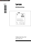
Handbuch/Manual
Global Drive
Global Drive Control (GDC)
Erste Schritte/Getting Started
Deutsch . . . . . . . . . . . . . . . . . . . . . . . . . . . . . . . . . . . . . . . . . . . . . . . . . . . . . . . . .
1
English . . . . . . . . . . . . . . . . . . . . . . . . . . . . . . . . . . . . . . . . . . . . . . . . . . . . . . . . .
35
Global Drive Control
ACHTUNG:
Die Software wird dem Benutzer in der vorliegenden Form zur Verfügung gestellt. Alle Risiken
hinsichtlich der Qualität und der durch ihren Einsatz ermittelten Ergebnisse verbleiben beim
Benutzer. Entsprechende Sicherheitsvorkehrungen gegen eventuelle Fehlbedienungen sind
vom Benutzer vorzusehen.
Wir übernehmen keine Verantwortung für direkt oder indirekt entstandene Schäden, z. B.
Gewinnverluste, Auftragsverluste oder geschäftliche Beeinträchtigungen jeglicher Art.
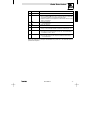
Stand
ID−Nr.
Änderungen
1.0
10/1998 TD05 00403781
Erstauflage
1.1
09/1999 TD05 00410149
Zweisprachig Deutsch/Englisch
2.0
04/2002 TD05 00452507
Überarbeitete und aktualisierte Auflage für GDC ab Version 4.4
3.0
09/2002 TD01 00458263
Umfirmierung
3.1
04/2003 TD05 00464347
Aktualisierte Auflage
3.2
06/2004 TD05 00494622
Systemanforderungen
4.0
12/2008 TD16 13282982
Neuauflage wegen Neuorganisation des Unternehmens
E 2008 Lenze Automation GmbH
Ohne besondere schriftliche Genehmigung von Lenze Automation GmbH darf kein Teil dieser
Dokumentation vervielfältigt oder Dritten zugänglich gemacht werden.
Wir haben alle Angaben in dieser Dokumentation mit größter Sorgfalt zusammengestellt und auf
Übereinstimmung mit der beschriebenen Hard− und Software geprüft. Trotzdem können wir
Abweichungen nicht ganz ausschließen. Wir übernehmen keine juristische Verantwortung oder Haftung
für Schäden, die dadurch eventuell entstehen. Notwendige Korrekturen werden wir in die
nachfolgenden Auflagen einarbeiten.
Windows, Windows NT und MS−DOS sind entweder eingetragene Warenzeichen oder Warenzeichen der
Microsoft Corporation in den U.S.A. und/oder anderen Ländern.
IBM und VGA sind eingetragene Warenzeichen von International Business Machines, Inc.
Alle anderen Markennamen sind Warenzeichen ihrer jeweiligen Besitzer.
L
GDC DE/EN 4.0
1
Inhaltsverzeichnis
1 Vorwort und Allgemeines . . . . . . . . . . . . . . . . . . . . . . . . . . . . . . . . . . . . . . . .
3
1.1
Verwendete Konventionen . . . . . . . . . . . . . . . . . . . . . . . . . . . . . . . . . . . . . . . . . . . . . . . . . .
3
1.2
1.3
Gestaltung der Sicherheitshinweise . . . . . . . . . . . . . . . . . . . . . . . . . . . . . . . . . . . . . . . . . . .
Lieferumfang . . . . . . . . . . . . . . . . . . . . . . . . . . . . . . . . . . . . . . . . . . . . . . . . . . . . . . . . . . .
4
4
2 Systemanforderungen . . . . . . . . . . . . . . . . . . . . . . . . . . . . . . . . . . . . . . . . . . .
5
2.1
Von Global Drive Control unterstützte Schnittstellen . . . . . . . . . . . . . . . . . . . . . . . . . . . . . . . .
5
3 Software−Installation . . . . . . . . . . . . . . . . . . . . . . . . . . . . . . . . . . . . . . . . . . .
6
3.1
Auswahl von Komponenten . . . . . . . . . . . . . . . . . . . . . . . . . . . . . . . . . . . . . . . . . . . . . . . . .
6
4 Erste Schritte mit Global Drive Control . . . . . . . . . . . . . . . . . . . . . . . . . . . . . .
7
4.1
Allgemeines . . . . . . . . . . . . . . . . . . . . . . . . . . . . . . . . . . . . . . . . . . . . . . . . . . . . . . . . . . . .
7
4.2
Starten des Programms . . . . . . . . . . . . . . . . . . . . . . . . . . . . . . . . . . . . . . . . . . . . . . . . . . . .
8
4.3
4.4
Zielsystem suchen (Online−Modus) . . . . . . . . . . . . . . . . . . . . . . . . . . . . . . . . . . . . . . . . . . . .
Zielsystem manuell auswählen (Offline−Modus) . . . . . . . . . . . . . . . . . . . . . . . . . . . . . . . . . . .
9
11
4.5
AIF−Modul dem Grundgerät zuordnen . . . . . . . . . . . . . . . . . . . . . . . . . . . . . . . . . . . . . . . . . .
12
4.6
4.7
FIF−Modul dem Grundgerät zuordnen . . . . . . . . . . . . . . . . . . . . . . . . . . . . . . . . . . . . . . . . . .
Kurzinbetriebnahme . . . . . . . . . . . . . . . . . . . . . . . . . . . . . . . . . . . . . . . . . . . . . . . . . . . . . . .
14
16
4.9
4.7.1
Beispiele für den Kurzinbetriebnahme−Dialog . . . . . . . . . . . . . . . . . . . . . . . . . . . . .
Die Bedienoberfläche von Global Drive Control . . . . . . . . . . . . . . . . . . . . . . . . . . . . . . . . . . .
4.8.1
Hauptfenster . . . . . . . . . . . . . . . . . . . . . . . . . . . . . . . . . . . . . . . . . . . . . . . . . . . .
4.8.2
Hauptmenü . . . . . . . . . . . . . . . . . . . . . . . . . . . . . . . . . . . . . . . . . . . . . . . . . . . . .
4.8.3
Symbolleiste . . . . . . . . . . . . . . . . . . . . . . . . . . . . . . . . . . . . . . . . . . . . . . . . . . . .
4.8.4
Statuszeile . . . . . . . . . . . . . . . . . . . . . . . . . . . . . . . . . . . . . . . . . . . . . . . . . . . . .
4.8.5
Fenster Antriebe am Bus" . . . . . . . . . . . . . . . . . . . . . . . . . . . . . . . . . . . . . . . . . .
4.8.6
Parameterfenster . . . . . . . . . . . . . . . . . . . . . . . . . . . . . . . . . . . . . . . . . . . . . . . . .
4.8.7
Eingabedialoge . . . . . . . . . . . . . . . . . . . . . . . . . . . . . . . . . . . . . . . . . . . . . . . . . .
4.8.8
Monitorfenster . . . . . . . . . . . . . . . . . . . . . . . . . . . . . . . . . . . . . . . . . . . . . . . . . . .
Funktionsblock−Editor . . . . . . . . . . . . . . . . . . . . . . . . . . . . . . . . . . . . . . . . . . . . . . . . . . . . .
16
18
18
19
20
21
21
22
24
25
26
4.10
4.11
Oszilloskopfunktion . . . . . . . . . . . . . . . . . . . . . . . . . . . . . . . . . . . . . . . . . . . . . . . . . . . . . . .
Eingabeassistent für Motordaten . . . . . . . . . . . . . . . . . . . . . . . . . . . . . . . . . . . . . . . . . . . . . .
27
28
5 Anhang . . . . . . . . . . . . . . . . . . . . . . . . . . . . . . . . . . . . . . . . . . . . . . . . . . . . . .
30
4.8
2
5.1
GDC als OPC−Client verwenden . . . . . . . . . . . . . . . . . . . . . . . . . . . . . . . . . . . . . . . . . . . . . . .
30
5.2
5.1.1
Busserver konfigurieren . . . . . . . . . . . . . . . . . . . . . . . . . . . . . . . . . . . . . . . . . . . .
5.1.2
GDC−Kommunikationsparameter konfigurieren . . . . . . . . . . . . . . . . . . . . . . . . . . . .
5.1.3
OPC−Antriebe suchen . . . . . . . . . . . . . . . . . . . . . . . . . . . . . . . . . . . . . . . . . . . . . .
5.1.4
Verwendung des Busserver S7−MPI . . . . . . . . . . . . . . . . . . . . . . . . . . . . . . . . . . . .
Schnittstellenwandler für LECOM−B (RS485) . . . . . . . . . . . . . . . . . . . . . . . . . . . . . . . . . . . . .
30
30
32
33
34
5.3
Häufig gestellte Fragen und Antworten . . . . . . . . . . . . . . . . . . . . . . . . . . . . . . . . . . . . . . . . .
34
GDC DE/EN 4.0
L
Global Drive Control
1
Vorwort und Allgemeines
Das Programm Global Drive Control (GDC) dient zur komfortablen Inbetriebnahme und Parametrie rung der Global Drive Antriebsreihen 8200 und 9300.
Die wesentlichen Eigenschaften von GDC sind:
· Geführte Inbetriebnahme mittels antriebsspezifischer Dialoge.
· Menügeführte Parametrierung. Gleichzeitige Darstellung des Menüs und der zugeordneten
Codestellen ähnlich des Windows Explorers.
· Parametrierung mit und ohne direkter Verbindung zum Antriebsregler (Online−/Offline−Betrieb).
Hierdurch Vorabparametrierung im Bürobereich möglich.
· Vereinfachte Funktionsblockparametrierung für Antriebsregler 93xx.
· Automatische Antriebserkennung beim Betrieb mit serieller Schnittstelle.
· Kommunikation über serielle Schnittstelle RS232/485, LWL−Ring oder Systembus möglich.
· Integrierte Schnittstelle für OPC (OLE for Process Control), dadurch kann GDC als OPC−Client auf
vom Lenze DriveServer unterstützte Busserver zugreifen.
· Vereinfachte Fehlersuche durch Diagnose−Funktionen.
· Monitorfenster zur Darstellung von 8 Parametern, die zyklisch aktualisiert werden. Die Werte
können durch unterschiedliche Visualisierungsfomen (Zeigerinstrument, Balken, Trend, Zahl)
dargestellt werden.
· Oszilloskopfunktion für Antriebsregler 93xx.
(93xx Servo ab Softwarestand 2.0, 93xx Vector ab Softwarestand 1.0)
· Funktionsblock−Editor für Antriebsregler 93xx.
· Eingabeassistent für Motordaten.
· PC−Parametersatzvergleich mit der Lenze−Werkseinstellung oder der aktuellen
Antriebseinstellung, um festzustellen, welche Parameter−Änderungen vorgenommen wurden.
· Kompletter Parametersatztransfer zwischen PC und Antriebsregler mit einem Befehl.
· Ausdruck der Parametereinstellungen zur Dokumentation.
· Speichern/Laden der Antriebskonfiguration zum Austausch zwischen verschiedenen Rechnern.
· Komfortables Online−Hilfesystem.
1.1
Verwendete Konventionen
Dieses Handbuch verwendet folgende Konventionen zur Unterscheidung verschiedener Arten von Information:
Informationsart
Auszeichnung
Beispiel
Namen von Dialogfeldern, Eingabefeldern und Auswahllisten
kursiv
Das Dialogfeld Optionen...
Schaltflächen
fett
Klicken Sie auf OK, um...
Menübefehle
fett
Mit dem Befehl Suchen können Sie...
Sind zum Ausführen einer Funktion mehrere Befehle
nacheinander erforderlich, sind die einzelnen Befehle durch einen Pfeil voneinander getrennt:
Wählen Sie OptionenWTools, um...
Tastaturbefehle
<fett>
Mit <F1> rufen Sie die Online−Hilfe auf.
Ist für einen Befehl eine Tastenkombination erforderlich, ist zwischen den Befehlen ein "+" gesetzt:
Mit <Shift>+<ESC> können Sie...
L
GDC DE/EN 4.0
3
Global Drive Control
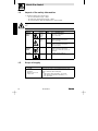
1.2
Gestaltung der Sicherheitshinweise
· Alle Sicherheitshinweise sind einheitlich aufgebaut:
– Das Piktogramm kennzeichnet die Art der Gefahr.
– Das Signalwort kennzeichnet die Schwere der Gefahr.
– Der Hinweistext beschreibt die Gefahr und gibt Hinweise, wie die Gefahr vermieden werden
kann.
Signalwort
Hinweistext
verwendete Piktogramme
Warnung vor
Personenschäden
1.3
Gefahr!
Warnt vor unmittelbar drohender Gefahr.
Folgen bei Mißachtung:
Tod oder schwerste Verletzungen.
Warnung vor
einer allgemeinen Gefahr
Warnung!
Warnt vor einer möglichen, sehr gefährlichen
Situation.
Mögliche Folgen bei Mißachtung:
Tod oder schwerste Verletzungen.
Vorsicht!
Warnt vor einer möglichen, gefährlichen Situation.
Mögliche Folgen bei Mißachtung:
leichte oder geringfügige Verletzungen.
Warnung vor
Sachschäden
Stop!
Warnt vor möglichen Sachschäden.
Mögliche Folgen bei Mißachtung:
Beschädigung des Antriebsreglers/Antriebssystems
oder seiner Umgebung.
Sonstige
Hinweise
Tip!
Kennzeichnet einen allgemeinen, nützlichen Tip.
Wenn Sie ihn befolgen, erleichtern Sie sich die
Handhabung des Produkts.
Lieferumfang
Lieferumfang
Wichtig
· 1 CD−ROM
Überprüfen Sie nach Erhalt der Lieferung sofort, ob der Lieferumfang mit
den Warenbegleitpapieren übereinstimmt. Für nachträglich reklamierte
Mängel übernimmt Lenze keine Gewährleistung.
Reklamieren Sie
· erkennbare Transportschäden sofort beim Anlieferer.
· erkennbare Mängel/Unvollständigkeit sofort bei der zuständigen
Lenze−Vertretung.
Global Drive Control"
· Dieses Handbuch
· Beiblatt Lizenz− und Vertrags bedingungen"
4
Signalwörter
Warnung vor
gefährlicher
elektrischer
Spannung
GDC DE/EN 4.0
L
Global Drive Control
2
Systemanforderungen
Um mit GDC arbeiten zu können, sind folgende Mindestanforderungen an Hard− und Software zu erfüllen:
· Microsoft © Windows© 98/Me, Windows NT© 4.0 (ab Service Pack 5),
Windows 2000 (ab Service Pack 2) oder Windows XP
· IBM−kompatibler PC mit Intel© Pentium ©−333 Prozessor
· 128 MB Arbeitsspeicher (RAM)
· 180 MB freie Festplattenkapazität
· CD−ROM Laufwerk
· Freie Steckplätze/Schnittstellen entsprechend den Anforderungen der einzusetzenden
Feldbus−Anschaltbaugruppe
Desweiteren empfehlen wir die Verwendung einer Maus.
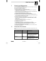
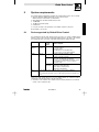
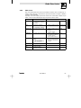
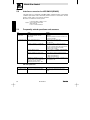
2.1
Von Global Drive Control unterstützte Schnittstellen
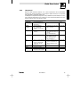
Zur Kommunikation mit dem Zielsystem (Antriebsregler, Drive PLC usw.) benötigen Sie für den PC eine
feldbusspezifische Anschaltbaugruppe sowie die dazu passenden Feldbusmodule für die anzuschließenden Antriebe. Die folgende Tabelle liefert eine Übersicht über die Übertragungsmedien, die von GDC
unterstützt werden:
Bussystem
Schnittstelle
am PC
max. Anzahl
Zielsysteme
erforderliche
Hardware−Komponenten
Systembus
(CANopen)
parallele
Schnittstelle
(LPT−Port)
63
Systembusmodul
inkl. Anschlußleitung und
Spannungsversorgungsadapter
· für DIN−Tastaturanschluß (EMF2173IB)
· für PS/2−Tastaturanschluß (EMF2173IBV002)
· für PS/2−Tastaturanschluß mit galvanischer Trennung
(EMF2173IBV003)
LECOM
Serielle
Schnittstelle
(COM−Port)
1
(RS232)
· Feldbusmodul EMF 2102IB V001 oder V004
· PC−Systemkabel RS232/485, 5m (EWL0020)
31
(RS485)
· Feldbusmodul EMF 2102IB V001
· PC−Systemkabel RS232/485, 5m (EWL0020)
· Schnittstellenwandler RS232/RS485 mit automatischer
52
(LWL)
Andere
Bussysteme
·
·
·
·
Richtungsumschaltung (nicht bei Lenze erhältlich; Bezugsquelle siehe Anhang. ^ 34)
Feldbusmodul EMF 2102IB V003
LWL−Adapter (EMF2125IB)
Netzteil für Adapter (EJ0013)
LWLKabel (EWZ0007)
Feldbusspezifische PC−Anschaltbaugruppe mit OPC−Busserver nach DRIVECOM−Spezifikation.
· Ausführliche Informationen zur Verwendung von GDC als OPC−Client finden Sie im Anhang.
(^ 30)
Um im GDC−Onlinemodus mit dem Zielsystem kommunizieren zu können, verbinden Sie das Zielsystem
mit dem PC über die entsprechende Schnittstelle/PC−Anschaltbaugruppe.
· Informationen zum Anschluß entnehmen Sie bitte der dem Feldbusmodul bzw. der
PC−Anschaltbaugruppe zugehörigen Betriebsanleitung.
L
GDC DE/EN 4.0
5
Global Drive Control
3
Software−Installation
Um die Software GDC auf Ihrem Rechner zu installieren, führen Sie die folgenden Schritte aus:
1. Starten Sie Windows.
2. Legen Sie die CD Global Drive Control" in Ihr CD−ROM−Laufwerk ein.
Ist die Autostart−Funktion Ihres CD−ROM−Laufwerks aktiviert, wird das Installationsprogramm
automatisch gestartet und Sie können mit Schritt 5 fortfahren.
3. Wählen Sie im Startmenü Ausführen... .
4. Geben Sie in die Befehlszeile den Laufwerksbuchstaben Ihres CD−ROM−Laufwerks gefolgt von
:\setup.exe" ein (z. B. e:\setup.exe") und bestätigen Sie mit Ok.
5. Folgen Sie den Anweisungen des Installationsprogramms.
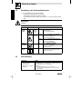
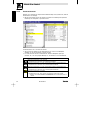
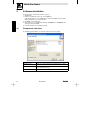
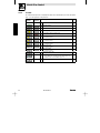
3.1
Auswahl von Komponenten
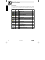
Im Installationsprogramm können Sie auswählen, welche Komponenten installiert werden sollen:
6
Komponente
Info
Global Drive Control
Software zur komfortablen Inbetriebnahme, Parametrierung und Diagnose der
Global Drive Antriebsreihen 8200 und 9300.
Global Drive Loader
Software, mit der vom PC aus SPS−Programme, Parametersätze und Applikations−Daten in Lenze Zielsysteme übertragen werden können.
Global Drive Oscilloscope
Software zum Aufzeichnen und Speichern von Meßwerten in Lenze PLCs.
GDC DE/EN 4.0
L
Global Drive Control
4
Erste Schritte mit Global Drive Control
4.1
Allgemeines
Das Programm GDC unterscheidet zwischen Online− und Offline−Modus.
· Offline:
Es besteht keine Verbindung zum Zielsystem. Dieser Modus ist sinnvoll zur Vorparametrierung
bzw. zur Dokumentation der Parametrierung im Büro. Außer dem PC sind keine weiteren
Komponenten erforderlich.
· Online:
GDC kommuniziert über die serielle/parallele Schnittstelle des PC bzw. über eine
feldbusspezifische PC−Anschaltbaugruppe mit dem Zielsystem. Diese Betriebsart ist für die
Inbetriebnahme des Zielsystems erforderlich.
Hinweis
GDC ist auf die serielle Schnittstelle COM2, bei Installationsauswahl "Systembus (CAN)−Anschaltung"
auf die Systembus (CAN)−Schnittstelle (500 kBaud/Parameterkanal 2) voreingestellt.
· Wenn Sie eine andere Schnittstelle verwenden möchten, müssen Sie diese in den
Kommunikationseinstellungen von GDC entsprechend konfigurieren.
(Siehe auch Tip auf der folgenden Seite.)
· Weitere Hinweise zur Kommunikation mit dem Zielsystem finden Sie in der GDC−Online−Hilfe.
L
GDC DE/EN 4.0
7
Global Drive Control
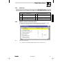
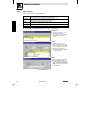
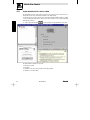
4.2
Starten des Programms
Wählen Sie im Startmenü ProgrammeWLenzeWGlobal Drive ControlWGlobal Drive Control.
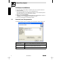
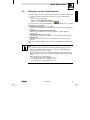
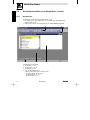
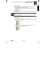
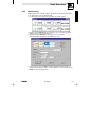
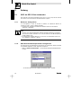
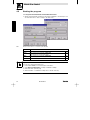
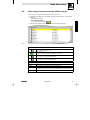
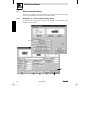
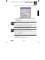
· Nach dem ersten Programmstart wird automatisch das Dialogfeld Antriebe suchen zur
voreingestellten Schnittstelle angezeigt, über das Sie eine Suche nach Antrieben im
Online−Modus durchführen oder in den Offline−Modus wechseln können:
Abb. 1
Dialogfeld Antriebe suchen" für Lecom−A/B bzw. Systembus (CAN)
Schaltfläche
Funktion/Hinweise
Suchen
Sucht nach an der entsprechenden Schnittstelle angeschlossenen Zielsystemen und
startet GDC im Online−Modus.
^9
Abbruch
Schließt das Dialogfeld und startet GDC im Online−Modus,
ohne eine Suche nach angeschlossenen Zielsystemen durchzuführen.
^9
Offline
Schließt das Dialogfeld und startet GDC im Offline−Modus,
ohne eine Suche nach angeschlossenen Zielsystemen durchzuführen.
^ 11
Hilfe
Öffnet die GDC−Online−Hilfe mit Informationen zu diesem Dialogfeld.
Tip!
Wenn Sie eine andere als die voreingestellte Schnittstelle verwenden:
1. Wählen Sie die Schaltfläche Abbruch, um das Dialogfeld Antriebe suchen zu schließen.
2. Wählen Sie OptionenWKommunikation, um die Kommunikationseinstellungen zu ändern.
3. Starten Sie eine erneute Suche. (Siehe folgende Seite)
Weitere Informationen zu den Kommunikationseinstellungen finden Sie in der GDC−Online−Hilfe.
8
GDC DE/EN 4.0
L
Global Drive Control
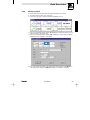
4.3
Zielsystem suchen (Online−Modus)
Das Dialogfeld Antriebe suchen wird automatisch geöffnet, wenn GDC im Online−Modus gestartet wird.
· Sie können das Dialogfeld Antriebe suchen auch über eine der folgenden Möglichkeiten
aufrufen:
– Drücken Sie die Funktionstaste F2
– Wählen Sie im Menü AntriebsreglerWSuchen.
– Klicken Sie in der Symbolleiste auf die Schaltfläche
Für die Suche können Sie verschiedene Einstellungen vornehmen, die abhängig von der verwendeten
Schnittstelle sind: (siehe auch Abb. 1)
· Alle Baudraten durchsuchen: (nur bei Lecom−A/B)
Aktivieren Sie das Kontrollkästchen, um alle Baudraten von 1200 bis 19200 Baud durchsuchen
zu lassen.
· Suche abbrechen, sobald ein Antrieb gefunden wird:
Aktivieren Sie das Kontrollkästchen, um die Suche abzubrechen, sobald ein Zielsystem
gefunden wurde.
· Slave−Antriebe suchen: (nur bei Lecom−A/B)
Aktivieren Sie das Kontrollkästchen, um während der Suche auch Slave−Antriebe zu erfassen.
· Geräteadressen:
Geben Sie in die Eingabefelder den Bereich der Geräteadressen ein, nach denen gesucht
werden soll.
Wählen Sie die Schaltfläche Suchen, um die Suche zu starten oder Abbruch, um die Suche abzubrechen.
Tip!
Für die gefundenen Zielsysteme versucht GDC automatisch, Gerätebeschreibungen zuzuordnen.
· Wurde nur ein Zielsystem gefunden und konnte dem Zielsystem eine Gerätebeschreibung
zugeordnet werden, wird diese sofort geladen.
· Gelingt die automatische Zuordnung der Gerätebeschreibung für ein Zielsystem nicht, wird ein
Dialogfeld angezeigt, über das Sie die entsprechende Gerätebeschreibung manuell auswählen
können.
Weitere Informationen zur manuellen Auswahl
– eines Grundgerätes finden Sie im Unterkapitel 4.4. (^ 11)
– eines AIF−Moduls finden Sie im Unterkapitel 4.5. (^ 12)
– von FIF−Modulen finden Sie im Unterkapitel 4.6. (^ 14)
L
GDC DE/EN 4.0
9
Global Drive Control
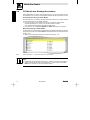
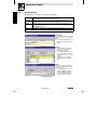
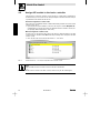
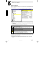
Fenster "Antriebe am Bus"
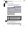
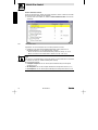
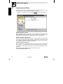
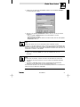
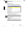
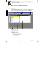
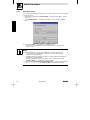
Alle am Bus gefundenen bzw. manuell zugeordneten Zielsysteme inklusive vorhandener AIF−/FIF−Module werden im Fenster Antriebe am Bus aufgelistet.
· Sollte das Fenster nicht sichtbar sein, wählen Sie FensterWAntriebe am Bus, um das Fenster
einzublenden.
Abb. 2
Fenster Antriebe am Bus
Doppelklicken Sie auf das Zielsystem, das Sie mit GDC parametrieren möchten.
· Daraufhin wird die entsprechende Gerätebeschreibungsdatei in GDC geladen und der
Kurzinbetriebnahmedialog bzw. das Parameterfenster angezeigt.
– Weitere Informationen zum Kurzinbetriebnahmedialog erhalten Sie im Kap. 4.7. (^ 16)
– Weitere Informationen zum Parameterfenster erhalten Sie im Kap. 4.8.6. (^ 22)
Tip!
Wenn Sie mit der rechten Maustaste auf einen Eintrag klicken, wird ein Kontextmenü mit einem Befehl
zur manuellen Zuordnung der Gerätebeschreibungsdatei angezeigt.
Mit dem Kontextmenü−Befehl:
· Grundgerät manipulieren rufen Sie das Dialogfeld Gerätebeschreibung dem Grundgerät
zuordnen auf. (^ 11)
· AIF manipulieren rufen Sie das Dialogfeld AIF−Modul dem Grundgerät zuordnen auf. (^ 12)
· FIF manipulieren rufen Sie das Dialogfeld FIF−Modul(e) dem Grundgerät zuordnen auf. (^ 14)
10
GDC DE/EN 4.0
L
Global Drive Control
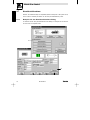
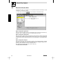
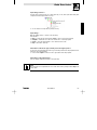
4.4
Zielsystem manuell auswählen (Offline−Modus)
Führen Sie die folgenden Schritte aus, um im Offline−Modus das Zielsystem manuell auszuwählen:
1. Rufen Sie das Dialogfeld Gerätebeschreibung dem Grundgerät zuordnen über eine der
folgenden Möglichkeiten auf:
– Drücken Sie die Funktionstaste F3
– Wählen Sie im Menü AntriebsreglerWWählen
– Klicken Sie in der Symbolleiste auf die Schaltfläche
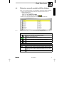
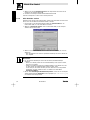
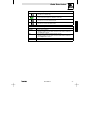
2. Wählen Sie das entsprechende Grundgerät im Listenfeld Gerätebeschreibung aus:
Abb. 3
Listenfeld Gerätebeschreibung im Dialogfeld Gerätebeschreibung dem Grundgerät zuordnen
Symbole im Dialogfeld und ihre Bedeutung
Kennzeichnet einen nicht ausgewählten Eintrag.
· Klicken Sie auf das Symbol, um diesen Eintrag auszuwählen.
Kennzeichnet einen ausgewählten Eintrag.
· Im unteren Textfeld werden Ihnen weitere Informationen zu diesem Eintrag angezeigt.
Kennzeichnet einen Eintrag, der weitere (ausgeblendete) Untereinträge enthält.
· Klicken Sie auf das Symbol, um die untergeordneten Einträge einzublenden.
Kennzeichnet einen Eintrag, der weitere (eingeblendete) Untereinträge enthält.
· Klicken Sie auf das Symbol, um die untergeordneten Einträge auszublenden.
Schaltflächen im Dialogfeld und ihre Bedeutung
L
Weiter
Weiter zum Dialogfeld AIF−Modul dem Grundgerät zuordnen.
Abbruch
Abbruch der Zuordnung, Dialogfeld ohne Übernahme durchgeführter Änderungen schließen.
Suchen (Pfad)
Laden einer Gerätebeschreibungsdatei (*.pdb) über das Dateisystem des PC.
· Wählen Sie im Dialogfeld Öffnen die Gerätebeschreibungsdatei aus, die in GDC geladen
werden soll.
Hilfe
Aufruf der Online−Hilfe
GDC DE/EN 4.0
11
Global Drive Control
4.5
AIF−Modul dem Grundgerät zuordnen
Ist am Grundsgerät ein AIF−Modul angeschlossen und erfolgt die Kommunikation PCóZielsystem über
dieses AIF−Modul, so kann in GDC die zum entsprechenden AIF−Modul zugehörige Gerätebeschreibung
geladen werden, um auch das AIF−Modul mit GDC parametrieren zu können.
Automatische Zuordnung im Online−Modus
Im Online−Modus wird ein vorhandenes AIF−Modul automatisch erkannt und im Fenster Antriebe am
Bus" aufgelistet. (^ 21)
· Durch Klicken mit der rechten Maustaste auf den Eintrag für das AIF−Modul steht Ihnen der
Befehl AIF manipulieren zur Verfügung, über den Sie das Dialogfeld AIF−Modul dem
Grundgerät zuordnen aufrufen (siehe folgenden Abschnitt Manuelle Zuordnung im
Offline−Modus).
Manuelle Zuordnung im Offline−Modus
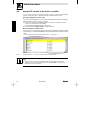
Im Offline−Modus erfolgt die Zuordnung des AIF−Moduls über das Dialogfeld AIF−Modul dem Grundgerät
zuordnen, das Sie über die Schaltfläche Weiter im Dialogfeld Gerätebeschreibung dem Grundgerät zuordnen aufrufen. (^ 11)
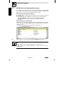
· Wählen Sie das entsprechende AIF−Modul im Listenfeld AIF−Modul für ... aus:
Abb. 4
Listenfeld AIF−Modul für ... im Dialogfeld AIF−Modul dem Grundgerät zuordnen
Tip!
Ist der PC nicht über das Interface des AIF−Moduls mit dem Grundgerät verbunden
− oder −
ist kein AIF−Modul am Grundgerät angeschlossen, so wählen Sie den Eintrag Kein
AIF−Modul/Keypad".
12
GDC DE/EN 4.0
L
Global Drive Control
Symbole im Dialogfeld und ihre Bedeutung
Kennzeichnet einen nicht ausgewählten Eintrag.
· Klicken Sie auf das Symbol, um diesen Eintrag auszuwählen.
Kennzeichnet einen ausgewählten Eintrag.
· Im unteren Textfeld werden Ihnen weitere Informationen zu diesem Eintrag angezeigt.
Kennzeichnet einen Eintrag, der weitere (ausgeblendete) Untereinträge enthält.
· Klicken Sie auf das Symbol, um die untergeordneten Einträge einzublenden.
Kennzeichnet einen Eintrag, der weitere (eingeblendete) Untereinträge enthält.
· Klicken Sie auf das Symbol, um die untergeordneten Einträge auszublenden.
Schaltflächen im Dialogfeld und ihre Bedeutung
L
Zurück
Zurückkehren zum Dialogfeld Gerätebeschreibung dem Grundgerät zuordnen.
Fertigstellen
Fertigstellen der ausgewählten Zuordnung.
· Diese Schaltfläche wird nur angezeigt, wenn das Grundgerät über keine FIF−Schnittstelle
verfügt, ansonsten wird stattdessen die Schaltfläche Weiter angezeigt.
Weiter
Weiter zum Dialogfeld FIF−Modul dem Grundgerät zuordnen.
· Diese Schaltfläche wird nur angezeigt, wenn das Grundgerät über eine FIF−Schnittstelle
verfügt, ansonsten wird stattdessen die Schaltfläche Fertigstellen angezeigt.
Abbruch
Abbruch der Zuordnung, Dialogfeld ohne Übernahme durchgeführter Änderungen schließen.
Hilfe
Aufruf der Online−Hilfe
GDC DE/EN 4.0
13
Global Drive Control
4.6
FIF−Modul dem Grundgerät zuordnen
Sind am Grundgerät ein oder mehrere FIF−Module angeschlossen, so können Sie die zugehörigen Gerätebeschreibungen laden, um auch die entsprechenden FIF−Module mit GDC parametrieren zu können.
Automatische Zuordnung im Online−Modus
Im Online−Modus wird ein vorhandenes FIF−Modul automatisch erkannt und im Dialogfeld FIF−Modul
dem Grundgerät zuordnen als ausgewählt" angezeigt.
· Sollte die automatisch erfolgte Auswahl nicht mit dem am Grundgerät angeschlossenen
FIF−Modul übereinstimmen, so können Sie die Zuordnung manuell vornehmen.
(Siehe folgenden Abschnitt Manuelle Zuordnung im Offline−Modus).
· Durch Klicken auf die Schaltfläche Fertigstellen bzw. Weiter übernehmen Sie die Auswahl.
Manuelle Zuordnung im Offline−Modus
Im Offline−Modus erfolgt die Zuordnung des FIF−Moduls über das Dialogfeld FIF−Modul(e) dem Grundgerät zuordnen, das Sie über die Schaltfläche Weiter im Dialogfeld AIF−Modul dem Grundgerät zuordnen
aufrufen. (^ 12)
· Wählen Sie das entsprechende FIF−Modul im Listenfeld FIF−Modul für ... aus:
Abb. 5
Listenfeld FIF−Modul für ... im Dialogfeld FIF−Modul dem Grundgerät zuordnen
Tip!
· Ist kein FIF−Modul am Grundgerät angeschlossen, so wählen Sie den Eintrag Kein FIF−Modul".
· Verfügt das Grundgerät über mehrere FIF−Schnittstellen, so können Sie über die Schaltfläche
Weiter mit der Zuordnung der weiteren FIF−Module fortfahren.
14
GDC DE/EN 4.0
L
Global Drive Control
Symbole im Dialogfeld und ihre Bedeutung
Kennzeichnet einen nicht ausgewählten Eintrag.
· Klicken Sie auf das Symbol, um diesen Eintrag auszuwählen.
Kennzeichnet einen ausgewählten Eintrag.
· Im unteren Textfeld werden Ihnen weitere Informationen zu diesem Eintrag angezeigt.
Kennzeichnet einen Eintrag, der weitere (ausgeblendete) Untereinträge enthält.
· Klicken Sie auf das Symbol, um die untergeordneten Einträge einzublenden.
Kennzeichnet einen Eintrag, der weitere (eingeblendete) Untereinträge enthält.
· Klicken Sie auf das Symbol, um die untergeordneten Einträge auszublenden.
Schaltflächen im Dialogfeld und ihre Bedeutung
L
Zurück
Zurückkehren zum vorherigen Dialogfeld.
Fertigstellen
Fertigstellen der ausgewählten Zuordnung.
Weiter
Weiter zum Dialogfeld 2. FIF−Modul dem Grundgerät zuordnen.
· Diese Schaltfläche wird nur angezeigt, wenn das Grundgerät über mehrere FIF−Schnittstellen verfügt, ansonsten wird stattdessen die Schaltfläche Fertigstellen angezeigt.
Abbruch
Abbruch der Zuordnung, Dialogfeld ohne Übernahme durchgeführter Änderungen schließen.
Hilfe
Aufruf der Online−Hilfe
GDC DE/EN 4.0
15
Global Drive Control
4.7
Kurzinbetriebnahme
Nachdem die Gerätebeschreibung des ausgewählten/gefundenen Zielsystems in GDC geladen wurde,
wird in der GDC−Voreinstellung automatisch der GDC−Dialog Kurzinbetriebnahme geöffnet.
4.7.1
Beispiele für den Kurzinbetriebnahme−Dialog
Die Funktionen im GDC−Dialog Kurzinbetriebnahme sind abhängig vom Zielsystem und werden daher
an dieser Stelle nur beispielhaft erklärt.
16
GDC DE/EN 4.0
L
Global Drive Control
Feld Schaltfläche
Funktion/Hinweise
Änderung der Einstellungen zur ausgewählten Konfiguration
Hilfe
Anzeige der Online−Hilfe
· Über die Schaltfläche Hilfe können Sie von jedem Dialogfeld aus die Online−Hilfe
mit gezielten Informationen zum jeweiligen Dialogfeld aufrufen.
· Allgemeine Informationen zum Umgang mit der Windows−Hilfe finden Sie in Ihrer
Windows−Dokumentation.
Start
· Startet das Zielsystem
Stop
· Stoppt das Zielsystem
Diagnose
Wechsel zum GDC−Dialog Diagnose
· Anzeige von Überwachungskonfiguration, Betriebszeit, Fehlermeldungen, usw.
Parametermenü
Schließen des GDC−Dialogs Kurzinbetriebnahme und Anzeige des Parametermenüs
· Zum Umgang mit dem Parametermenü siehe Kap. 4.8, Die Bedienoberfläche
von Global−Drive−Control". (^ 18)
Steuerung
Wechsel zum GDC−Dialog Steuerung
· Über diesen GDC−Dialog kann das Zielsystem in Betrieb genommen werden.
– nur im Online−Modus
– nur im Online−Modus
– nur im Online−Modus
Weitere Informationen zum jeweiligen Inbetriebnahme−Dialog finden Sie in der Online−Hilfe zum entsprechendem Zielsystem.
L
GDC DE/EN 4.0
17
Global Drive Control
4.8
Die Bedienoberfläche von Global Drive Control
4.8.1
Hauptfenster
Das Hauptfenster ist das eigentliche Anwendungsfenster von GDC.
· Alle anderen Fenster sind Dokumentfenster, die nur innerhalb dieses Anwendungsfensters
angezeigt werden können.
· Funktionen zur Anordnung der Anwendungsfenster sind im Menü Fenster untergebracht.
Das Haupfenster von GDC enthält
· das Hauptmenü , (^ 19)
· die Symbolleiste , (^ 20)
· die Statuszeile , (^ 21)
· sowie den GDC−Arbeitsbereich ,
in dem die weiteren GDC−Fenster angezeigt werden:
– das Fenster "Antriebe am Bus", (^ 21)
– das Parameterfenster
, (^ 22)
– das Monitorfenster, (^ 25)
18
GDC DE/EN 4.0
L
Global Drive Control
4.8.2
Hauptmenü
Neben den häufig verwendeten Funktionen, die z. B. über die Symbolleiste oder die Funktionstasten
zugänglich sind, enthält das Hauptmenü von GDC zahlreiche spezielle Funktionen, die entsprechend
ihrer Funktionalität in Untermenüs gruppiert sind.
In Abhängigkeit des ausgewählten Zielsystems und des gewählten Modus (Online/Offline) kann es sein,
daß ein Untermenü ausgeblendet ist bzw. Funktionen in diesem Untermenü abgeblendet sind. Abgeblendete Funktionen können nicht aufgerufen werden.
Untermenü
Funktionen
Antriebsregler
·
·
·
·
Antriebs−
parameter
FB−Editor
Hinweise
Parametersatztransfer
PC ó Antriebsregler
· Parameter laden/speichern/
drucken
· Untermenü wird nur im Online−
^ Online−Hilfe
Modus angezeigt.
· spezielle Funktionsblock−Editor− · Untermenü wird nur bei aktivier- ^ 26
Funktionen
Oszilloskop
^ 9, 11
Suchen/Wählen/Start/Stop
Kommunikationsparameter
GDC beenden
tem Funktionsblock−Editor angezeigt.
· nur Antriebsregler 93xx
· spezielle Oszilloskop−Funktionen · Untermenü wird nur bei aktivier- ^ 27
tem Oszilloskop angezeigt.
· nur Antriebsregler 93xx
ab Softwarestand 2.x
Tool
· Aufruf von benutzerdefinierbaren Tools von GDC aus
· Aufruf von optionalen GDC−
Komponenten (FB−Editor,
Oszilloskop)
Optionen
Fenster
Hilfe
L
·
·
·
·
Voreinstellungen zum Programm
· In dieses Untermenü können ex- ^ Online−Hilfe
terne Programme eingebunden
werden, die dann direkt von
GDC aus aufgerufen werden
können.
^ Online−Hilfe
Anordnung der Fenster
Anzeige der Online−Hilfe
Informationen zum Programm
GDC DE/EN 4.0
19
Global Drive Control
4.8.3
Symbolleiste
Über die Symbolleiste haben Sie einen bequemen Zugriff auf häufig benötigte Funktionen. Alternativ
zur Symbolleiste können Sie für viele Funktionen auch die Funktionstasten Ihrer PC−Tastatur verwenden.
Schaltfläche
aktiviert
Schaltfläche
deaktiviert
Funktionstaste/Funktion
F1
Anzeige der kontextsensitiven Hilfe.
Antriebsfenster schließen.
20
F2
Zielsystem suchen (Online−Modus).
^9
F3
Zielsystem wählen (Offline−Modus).
^ 11
F4
Umschalten zwischen Online−/Offline−Modus
^9
^ 11
F5
Parametersatz vom PC zum Zielsystem übertragen.
· nur im Online−Modus
F6
Markierten Parameter vom Zielsystem in den PC übertragen.
· nur im Online−Modus
F7
Parametersatz vom Zielsystem in den PC übertragen.
· nur im Online−Modus
F8
Zielsystem starten.
· nur im Online−Modus
F9
Zielsystem stoppen.
· nur im Online−Modus
Funktionsblock−Editor starten.
· nur bei Antriebsreglern 93xx
^ 26
Oszilloskopfunktion starten.
· nur bei Antriebsreglern 93xx Servo ab Softwarestand 2.0 und
93xx Vector ab Softwarestand 1.0
^ 27
Eingabeassistent für Motordaten starten.
^ 28
GDC DE/EN 4.0
L
Global Drive Control
4.8.4
Statuszeile
Angezeigte Informationen in der Statuszeile
Hinweise zu gerätespezifischen
IMP: Impulssperre im Zielsystem gesetzt
Parametermenüs
/ Statusinformationen bei antriebsspezifischen
Aktueller Modus (Online/Offline)
Dialogen
TRIP: Störung im Zielsystem aufgetreten
RSP: Reglersperre im Zielsystem gesetzt
Online−Adresse (CAN oder LECOM−A/B)
Aktiver Parametersatz (nur im Online−Modus
bei 8200 vector/motec)
4.8.5
Fenster Antriebe am Bus"
Im Fenster Antriebe am Bus werden alle verfügbaren Zielsysteme inklusive vorhandener AIF−/FIF−Module aufgelistet.
· Wählen Sie in diesem Fenster per Doppelklick das Zielsystem aus, das Sie parametrieren
möchten.
Abb. 6
Fenster Antriebe am Bus
· Informationen zur manuellen Zuordnung von Zielsystemen finden Sie auf Seite 10ff. (^ 10)
L
GDC DE/EN 4.0
21
Global Drive Control
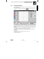
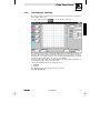
4.8.6
Parameterfenster
Nachdem für ein Zielsystem die entsprechende Gerätebeschreibung in GDC geladen wurde, steht das
Parameterfenster zur Verfügung.
· Mit Hilfe dieses Fensters können auf einfache Art und Weise alle Antriebssystem−spezifischen
Einstellungen des Zielsystems vorgenommen werden.
Das Parameterfenster ist in zwei Bereiche unterteilt:
· Auf der linken Seite befindet sich das Parametermenü, hier können Sie den Menüpunkt
auswählen, für den Sie Einstellungen vornehmen möchten.
· Die rechte Seite stellt die zum im Parametermenü aktiviertem Menüpunkt zugehörigen
Parameter dar, in der oben gezeigten Abbildung z. B. die Parameter für den Drehzahlbetrieb.
Symbole im Parametermenü und ihre Bedeutung
Menüpunkt im Parametermenü, nicht ausgewählt.
· Doppelklicken Sie auf das Symbol, um den Menüpunkt auszuwählen.
Menüpunkt im Parametermenü, der weitere Untermenüpunkte enthält. Die Untermenüpunkte sind
ausgeblendet.
· Doppelklicken Sie auf das Symbol, um die Untermenüpunkte einzublenden.
Menüpunkt im Parametermenü, der weitere Untermenüpunkte enthält. Die Untermenüpunkte sind
eingeblendet.
· Doppelklicken Sie auf das Symbol, um die Untermenüpunkte auszublenden.
Menüpunkt im Parametermenü, ausgewählt.
· Die rechte Seite des Parameterfenster dient für Ausgaben zu diesem aktivierten Menüpunkt.
· Bei Menüpunkten, die mit Dialog" beginnen, wird stattdessen ein GDC−Dialog geöffnet.
– Wählen Sie die Schaltfläche Zurück bzw. Parametermenü, um diesen GDC−Dialog wieder zu
schließen.
22
GDC DE/EN 4.0
L
Global Drive Control
Parameter auswählen
Einen auf der rechten Seite im Parameterfenster dargestellten Parameter des Zielsystems können Sie
mit der rechten Maustaste oder den Pfeiltasten auswählen.
· Der ausgewählte Parameter wird durch einen gelben Hintergrund hervorgehoben.
· Durch Betätigen der Funktionstaste F1 öffnen Sie die Online−Hilfe mit Informationen zum
ausgewählten Parameter.
Parameter ändern
Das Ändern eines ausgewählten Parameters erfolgt über einen Eingabedialog, den Sie durch Betätigen
der Taste Enter öffnen.
Tip!
Mit der linke Maustaste können Sie einen Parameter auswählen und gleichzeitig den Eingabedialog
zum Ändern des Parameters öffnen.
Weitere Informationen zu den Eingabedialogen finden Sie im folgenden Kapitel. (^ 24)
Codestellen/Objekte
Bei den Parametern wird zwischen Codestellen und Objekten unterschieden:
· Codestellen sind in der Spalte "Code" durch ein vorangestelltes "C" gekennzeichnet und stellen
die bekannten Lenze−Codestellen dar.
· Objekte sind in der Spalte "Code" durch ein vorangestelltes "I" gekennzeichnet und stellen
Parameter dar, die eine hexadezimale Adressierung verwenden.
L
GDC DE/EN 4.0
23
Global Drive Control
4.8.7
Eingabedialoge
Alle Eingabedialoge verfügen über die folgenden vier Schaltflächen:
Ok
Der selektierte/eingegebene Wert wird übernommen, der Eingabedialog wird beendet.
· Im Online−Modus wird der Wert zum Zielsystem übertragen.*
Übernahme
Der selektierte/eingegebene Wert wird übernommen, der Eingabedialog bleibt geöffnet.
· Im Online−Modus wird der Wert zum Zielsystem übertragen.*
Abbruch
Der Eingabedialog wird beendet, ohne daß durchgeführte Änderungen übernommen werden.
· Ausnahme: Die durchgeführten Änderungen wurden bereits durch Betätigen der Schaltfläche
Übernahme übernommen.
Hilfe
Die Online−Hilfe mit Informationen zum ausgewählten Parameter wird geöffnet.
* Einige Parameter können im Online−Modus nur geändert werden, wenn im Zielsystem Reglersperre gesetzt ist.
Die Darstellung des Parameterwertes ist abhängig von der Art des Parameters:
Auswahl (Liste)
Aus einer Liste können Sie für den ausgewählten Parametere eine neue Einstellung
wählen.
· Der aktuell eingestellte Wert ist beim
Öffnen des Eingabedialogs in der Liste
selektiert.
Bitcodiert
Der Wert des Parameters ist bitcodiert.
· In einer Liste werden alle Bits und
ihre Bedeutung aufgeführt.
· Den ausgewählten Wert können Sie
mit der linken Maustaste oder mit der
Leertaste zwischen 0 und 1 wechseln
("toggeln").
· Alternativ können Sie den Parameterwert Dezimal bzw. Hexadezimal
eingeben.
Dezimal
Innerhalb eines angezeigten Zahlenbereiches können Sie den Parameterwert über
die Tastatur eingeben.
· Zu einigen Parametern stehen im Eingabedialog zusätzlich die Schaltflächen Up und Down zur Verfügung,
über die Sie den Parameterwert in festen Schritten verändern können.
24
GDC DE/EN 4.0
L
Global Drive Control
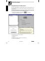
4.8.8
Monitorfenster
Das Monitorfenster dient zur Anzeige von Werten, die zyklisch vom Antriebsregler gelesen werden.
· Das Monitorfenster ist nur im Online−Modus aktiv.
· Im Offline−Modus wird das Monitorfenster automatisch zum Symbol verkleinert.
· Klicken Sie mit der linken Maustaste auf ein Teilfenster, um es zu vergrößern. Ein weiterer
Mausklick stellt die vorherige Ansicht wieder her.
· Klicken Sie mit der rechten Maustaste auf ein Teilfenster, um das Dialogfeld
Monitorkonfiguration zum Konfigurieren der Darstellung zu öffnen:
· Sie können nun für die im Feld Monitor mit blauem Hintergrund dargestellte Anzeige die
entsprechenden Einstellungen vornehmen oder durch Anklicken einer anderen Anzeige im Feld
Monitor zu deren Einstellungen wechseln.
L
GDC DE/EN 4.0
25
Global Drive Control
4.9
Funktionsblock−Editor
Der Funktionsblock−Editor ist ein leistungsfähiges Werkzeug, mit dem Signalkonfigurationen in Lenze−
Antriebsreglern 93xx erstellt, diagnostiziert und analysiert werden können.
· Klicken Sie in der Symbolleiste auf die Schaltfläche
, um das Dialogfeld FB−Editor zu
öffnen.
Signalkonfiguration erstellen
Mit Hilfe des Mauszeigers lassen sich Verbindungen zwischen Funktionsblöcken herstellen sowie bestehende Verknüpfungen entfernen. Darüber hinaus können die Parameter der Funktionsblöcke (z. B.
Hochlauframpe oder Maximaldrehzahl) mit dem Funktionsblock−Editor eingestellt werden.
Signalkonfiguration diagnostizieren
An den Ein− und Ausgängen der Funktionsblöcke lassen sich Istwerte einblenden, die zyklisch aktualisiert werden. Diese Signale können durch Mausklick von Funktionsblock zu Funktionsblock verfolgt
werden, um Fehler im Signalfluß aufzuspüren. Außerdem liefert der Funktionsblock−Editor Informationen zur Abarbeitungsreihenfolge der einzelnen Funktionsblöcke.
Signalkonfiguration analysieren
Jeder Funktionsblock, der in der Signalkonfiguration verwendet wird, kann grafisch dargestellt werden.
Einzelne Signale (z. B. Drehzahlsollwert) lassen sich mit Hilfe des Mauszeigers durch die gesamte Signalkonfiguration verfolgen. Dabei geben die Parameter der Funktionsblöcke Aufschluß über die jeweilige Funktion.
Weitere Informationen zum Funktionsblock−Editor erhalten Sie, indem Sie im
Menü HilfeWFunktionsblockeditor wählen.
26
GDC DE/EN 4.0
L
Global Drive Control
4.10
Oszilloskopfunktion
Für Antriebsregler 93xx Servo ab Softwarestand 2.0 (93xx Vector ab Softwarestand 1.0) verfügt GDC
über eine Oszilloskopfunktion.
· Klicken Sie in der Symbolleiste auf die Schaltfläche
, um das Dialogfeld Oszilloskop zu
öffnen.
Die Oszilloskopfunktion dient zur Messung beliebiger Signale, die vom Antriebsregler verarbeitet
werden. Dazu befindet sich im Antriebsregler ein Funktionsblock (OSZ), der wie ein Speicheroszilloskop
arbeitet. Dieser Funktionsblock kann bis zu vier analoge Signale gleichzeitig messen und aufzeichnen.
Die Triggerung erfolgt entweder über einen zusätzlichen digitalen Eingang oder über einen der vier analogen Kanäle.
Die Speicherung der Daten erfolgt im Antriebsregler. Nach Abschluß einer Messung werden diese Daten
zum PC übertragen und mit Hilfe der Oszilloskopfunktion in GDC visualisiert.
Die Kommunikation zwischen Antriebsregler und Visualisierungsfunktion ist nur möglich über
· LECOM−A/B
· Systembus
Weitere Informationen zur Oszilloskop−Funktion erhalten Sie, indem Sie im
Menü HilfeWOszilloskop wählen.
L
GDC DE/EN 4.0
27
Global Drive Control
4.11
Eingabeassistent für Motordaten
Mit Hilfe des Eingabeassistenten für Motordaten können Sie aus einer Liste mit Lenze−Motoren oder
einer anwenderdefinierten Liste den verwendeten Motor auswählen und dessen Motordaten in das Zielsystem übertragen.
Die Anwender−Motorenliste läßt sich um weitere Motortypen ergänzen, die entweder direkt eingegeben
oder mit Hilfe der Importfunktion aus einer Datei hinzugeladen werden. Über die Exportfunktion kann
die Motorenliste anderen Rechnern mit GDC zur Verfügung gestellt werden.
· Klicken Sie in der Symbolleiste auf die Schaltfläche
, um das Dialogfeld
Eingabeassistent für Motordaten zu öffnen.
Der Eingabeassistent ist in vier Bereiche unterteilt:
Eingabedialog−Übersicht
Eingabedialog
Informationen zum aktuell im Zielsystem eingestellten Motortyp
Informationen zum Eingabedialog
28
GDC DE/EN 4.0
L
Global Drive Control
Eingabedialog−Übersicht
Anhand der Eingabedialog−Übersicht können Sie entnehmen, in welchem Eingabeschritt Sie sich momentan befinden, welche Eingaben bereits erledigt sind und welche Eingaben noch vorgenommen
werden müssen:
· Indem Sie auf einen Eintrag klicken, können Sie zum entsprechenden Eingabedialog wechseln.
Eingabedialog
Nehmen Sie im Eingabedialog die entsprechende Auswahl bzw. die erforderlichen Eingaben vor.
Wählen Sie die Schaltfläche
· Weiter, um mit dem nächsten Eingabeschritt fortzufahren bzw. Zurück, um zum vorherigen
Eingabeschritt zurückzukehren.
· Fertigstellen, um die Motordaten des ausgewählten Motors in das Zielsystem zu übertragen.
· Abbrechen, um den Eingabeassistent für Motordaten abzubrechen und zu GDC zurückzukehren.
· Hilfe, um die GDC−Online−Hilfe aufzurufen.
Informationen zum aktuell im Zielsystem eingestellten Motortyp
In diesem Bereich wird Ihnen im Online−Modus angezeigt, welcher Motortyp aktuell im Zielsystem eingestellt ist und aus welcher Motorenliste er stammt.
· Wählen Sie die Schaltfläche Aktualisieren, um den eingestellten Motortyp aus dem Zielsystem
erneut auszulesen.
Informationen zum Eingabedialog
In diesem Bereich werden Ihnen Zusatzinformationen zum jeweiligen Eingabedialog angezeigt.
Tip!
Weitere Informationen zum Eingabeassistenten für Motordaten erhalten Sie, indem Sie die
Schaltfläche Hilfe wählen.
L
GDC DE/EN 4.0
29
Global Drive Control
5
Anhang
5.1
GDC als OPC−Client verwenden
GDC verfügt über eine integrierte Schnittstelle für OPC (OLE for Process Control) und kann somit als
OPC−Client auf vom Lenze DriveServer unterstützte Busserver zugreifen.
5.1.1
Busserver konfigurieren
Vor der Konfiguration von GDC als OPC−Client ist zunächst der entsprechende Busserver zu
konfigurieren, damit er in GDC zur Auswahl bereitsteht.
· Informationen zur Konfiguration des Busservers entnehmen Sie bitte der zum Busserver
zugehörigen Dokumentation.
Tip!
· Busserver für die beiden Feldbussysteme LECOM und Systembus (CAN) sind im Lieferumfang
des DriveServer enthalten, desweiteren ist von Lenze ein Busserver für den MPI−Bus (Busserver
S7−MPI) erhältlich. (^ 33)
· Eine Übersicht über verfügbare Busserver von Lenze sowie von Fremdherstellern finden Sie in
der Dokumentation DriveServer – Zubehör".
5.1.2
GDC−Kommunikationsparameter konfigurieren
Um mit GDC über die OPC−Schnittstelle mit dem DriveServer zu kommunizieren, müssen Sie zunächst
die Kommunikationsparameter in GDC entsprechend konfigurieren:
1. Wählen Sie OptionenWKommunikation..., um das Dialogfeld Auswahl Kommunikationstreiber
zu öffnen:
– Im Listenfeld werden Ihnen alle verfügbaren Kommunikationstreiber angezeigt.
30
GDC DE/EN 4.0
L
Global Drive Control
2. Selektieren Sie im Listenfeld den Eintrag OPC und wählen Sie die Schaltfläche Parameter...,
um das Dialogfeld OPC zu öffnen:
3. Geben Sie in das Eingabefeld Rechnername den Namen des PC ein, auf dem der Busserver
installiert ist.
– Über die Schaltfläche Netzwerk können Sie den entsprechenden PC aus Ihrer
Netzwerkumgebung auswählen.
– Wenn sich der Busserver auf dem gleichen PC wie GDC befindet, lassen Sie das Eingabefeld
Rechnername einfach leer.
Tip!
Beachten Sie folgendes, wenn Sie auf einen Busserver über ein Netzwerk zugreifen:
Um einen PC vor unbefugten Zugriffen zu schützen, verbieten die DCOM−Sicherheitseinstellungen standardmäßig den OPC−Zugriff. Kontrollieren Sie daher die DCOM−Einstellungen für den entsprechenden
Busserver und verändern Sie diese gegebenenfalls. Ausführliche Informationen hierzu finden Sie in der
Dokumentation DriveServer – Erste Schritte".
4. Wählen Sie die Schaltfläche Refresh, um die Liste der verfügbaren OPC−Server zu
aktualisieren.
Tip!
An dieser Stelle wird zwischen normalen" OPC−Servern und OPC−Busservern unterschieden:
· Bei einfachen OPC−Servern (Data Access 2.0) ist in der Regel eine aufwendige Konfiguration
notwendig.
· OPC−Busserver (DRIVECOM) dagegen sind für die Zusammenarbeit mit GDC/DriveServer
optimiert worden und kommen daher mit einer Minimalkonfiguration aus.
Aus diesem Grund empfehlen wir, nur OPC−Server mit Ausprägung als Busserver zu verwenden (Voreinstellung OPC−Optionen: þ Busserver (DRIVECOM) ).
L
GDC DE/EN 4.0
31
Global Drive Control
5. Wählen Sie im Listenfeld Verfügbare OPC−Server den entsprechenden OPC−Server aus und
schließen Sie das Dialogfeld OPC mit Ok.
6. Schließen Sie das Dialogfeld Auswahl Kommunikationstreiber mit Ok.
Damit ist die Konfiguration von GDC als OPC−Client abgeschlossen.
5.1.3
OPC−Antriebe suchen
Nachdem Sie GDC als OPC−Client konfiguriert haben, können Sie im Online−Modus eine Suche durchführen, um die am OPC−Busserver befindlichen Antriebe zu erfassen:
1. Falls sich GDC noch im Offline−Modus befindet, wählen Sie OptionenWOnline bzw. die
Funktionstaste <F4>, um in den Online−Modus zu wechseln.
2. Wählen Sie AntriebsreglerWSuchen... bzw. die Funktionstaste <F2>, um das Dialogfeld
Antrieb am OPC suchen zu öffnen:
3. Wählen Sie die Schaltfläche Suchen, um die Suche zu starten oder Abbruch, um die Suche
abzubrechen.
– Nach durchgeführter Suche werden die gefundenen Antriebsregler im Fenster Antriebe am
Bus" aufgelistet.
Hinweise!
· Für die gefundenen Antriebsregler versucht GDC automatisch, Gerätebeschreibungen
zuzuordnen.
– Wurde nur ein Antrieb gefunden und eine Gerätebeschreibung konnte zugeordnet werden,
wird diese sofort geladen.
– Gelingt die automatische Zuordnung der Gerätebeschreibung für einen Antrieb nicht, kann
für diesen Antrieb die Gerätebeschreibung manuell zugeordnet werden.
Um den Dialog für die manuelle Zuordnung zu öffnen, aktivieren Sie den entsprechenden
Antriebsregler im Fenster Antriebe am Bus" oder wählen Sie im Offline−Modus
AntriebsreglerWWählen....
· Mit dem Befehl AntriebsreglerWKommunikationsparameter... können Sie sich im Dialogfeld
Aktueller Antrieb im Textfeld Zugriffspfad den OPC−Zugriffspfad (z. B. COM1.Device_01)
zum aktuellen Antrieb anzeigen lassen.
32
GDC DE/EN 4.0
L
Global Drive Control
5.1.4
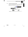
Verwendung des Busserver S7−MPI
Im Zusammenspiel mit dem Busserver S7−MPI besteht nun auch mit GDC die Möglichkeit, Zielsysteme
zu parametrieren, die über PROFIBUS−DP vernetzt sind und über Siemens SIMATIC S7 SPS gesteuert
werden.
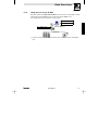
Die folgende Abbildung zeigt die Architektur eines solchen Systems:
Global Drive Control
Busserver S7−MPI
MPI
Funktionsbaustein
Siemens SIMATIC S7
PROFIBUS−DP
· Lediglich die Oszilloskopfunktion von GDC steht über diesen Kommunikationsweg nicht zur
Verfügung.
L
GDC DE/EN 4.0
33
Global Drive Control
5.2
Schnittstellenwandler für LECOM−B (RS485)
Soll die Kommunikation mit dem Zielsystem über LECOM−B (RS485) erfolgen, so ist hierfür ein intelligenter Schnittstellenwandler RS232óRS485 erforderlich, der die Kommunikationsrichtung automatisch umschalten kann. Der Lenze−Schnittstellenwandler 2100 erfüllt diese Funktion nicht.
Wir empfehlen daher die Verwendung des folgenden Produkts:
I−7520 galvanisch getrennter RS232 auf RS485 Wandler
Anbieter: Spectra Computersysteme GmbH
Humboldstraße 36
70771 Leinfelden/Echterdingen
5.3
Häufig gestellte Fragen und Antworten
Fehler
Ursache
Abhilfe
Parametersatzdateien
können nicht eingelesen
werden.
Sie haben versucht, Parametersatzdateien
einzulesen, die mit dem DOS−Programm
Lemoc2" hergestellt wurden.
GDC verwendet für die Ablage der Antriebsparameter
ein anderes Dateiformat.
Übertragen Sie den Parametrsatz aus den Antriebsregler in den PC und speichern Sie diesen mit GDC ab.
Keine Kommunikation
mit dem Antriebsregler.
Es wird ein falsches PC−Systemkabel verwendet.
Überprüfen Sie die Verdrahtung des Systemkabels.
(Die Belegung des Systemkabels finden Sie in der
GDC−Online−Hilfe.)
Antriebsregler ist ausgeschaltet bzw. das
LECOM−A/B−Modul 2102 hat keine Spannung.
Antriebsregler mit Spannung versorgen und korrekte
Verbindung mit dem Antriebsregler überprüfen.
Bei externer Spannungsversorgung an den Klemmen
39 und 59 die Spannung überprüfen (siehe Betriebsanleitung zum Antriebsregler).
Es wurde der falsche COM−Port gewählt.
Verwendeten COM−Port über OptionenWKommunikation einstellen.
Die Schnittstellenparameter sind nicht korrekt eingestellt.
Mit Hilfe der Windows−Systemsteuerung können die
Schnittstellenparameter geändert werden:
· COM1: Adresse 03F8, IRQ 4
· COM2: Adresse 02F8, IRQ 3
Die Windows−Konfiguration ist fehlerhaft.
Installieren Sie Windows erneut oder beheben Sie in
Hinweis: Mit dem Windows−Programm Ter- der Datei System.ini" Fehler in der Konfiguration.
minal" (Startmenü/Programme/Zubehör)
kann ebenfalls nicht auf die COM−Ports zugegriffen werden.
GDC mit Systembus
Fehler
Ursache
Absturz von GDC oder
Windows
Abziehen des PC−Systembusmoduls während PC−Systembusmodul nicht von der Schnittstelle abzieWindows läuft.
hen bzw. auf die Schnittstelle stecken während Windows läuft.
34
Abhilfe
GDC DE/EN 4.0
L
Global Drive Control
CAUTION:
The software is supplied to the user as described in this document. Any risks resulting from
its quality or use remain the responsibility of the user. The user must provide all safety
measures protecting against possible maloperation.
We do not take any liability for direct or indirect damage, e.g. profit loss, order loss or any
loss regarding business.
Version
ID no.
Changes
1.0
10/1998 TD05 00403781
First edition
1.1
09/1999 TD05 00410149
Bilingual German/English
2.0
04/2002 TD27 00452507
Revised and updated edition for GDC as from version 4.4
3.0
09/2002 TD01 00458263
Change of company name
3.1
04/2003 TD05 00464347
Revised edition
3.2
06/2004 TD05 00494622
System requirements
4.0
12/2008 TD16 13282982
New edition due to reorganisation of the company
E 2008 Lenze Automation GmbH
No part of this documentation may be copied or made available to third parties without the explicit
written approval of Lenze Automation GmbH.
All information given in this online documentation has been carefully selected and tested for
compliance with the hardware and software described. Nevertheless, discrepancies cannot be ruled
out. We do not accept any responsibility or liability for any damage that may occur. Required corrections
will be included in updates of this documentation.
Windows, Windows NT and MS−DOS are either registered trademarks or trademarks of Microsoft
Corporation in the U.S.A and/or other countries.
IBM and VGA are registered trademarks of International Business Machines, Inc.
All other product names are trademarks of the corresponding owners.
L
GDC DE/EN 4.0
35
Contents
1 Preface and general information . . . . . . . . . . . . . . . . . . . . . . . . . . . . . . . . . . .
37
1.1
Conventions used . . . . . . . . . . . . . . . . . . . . . . . . . . . . . . . . . . . . . . . . . . . . . . . . . . . . . . . .
37
1.2
1.3
Layout of the safety information . . . . . . . . . . . . . . . . . . . . . . . . . . . . . . . . . . . . . . . . . . . . . .
Scope of supply . . . . . . . . . . . . . . . . . . . . . . . . . . . . . . . . . . . . . . . . . . . . . . . . . . . . . . . . .
38
38
2 System requirements . . . . . . . . . . . . . . . . . . . . . . . . . . . . . . . . . . . . . . . . . . .
39
2.1
Ports supported by Global Drive Control . . . . . . . . . . . . . . . . . . . . . . . . . . . . . . . . . . . . . . . .
39
3 Software installation . . . . . . . . . . . . . . . . . . . . . . . . . . . . . . . . . . . . . . . . . . . .
40
3.1
Component selection . . . . . . . . . . . . . . . . . . . . . . . . . . . . . . . . . . . . . . . . . . . . . . . . . . . . . .
40
4 First steps with Global Drive Control . . . . . . . . . . . . . . . . . . . . . . . . . . . . . . .
41
4.1
General . . . . . . . . . . . . . . . . . . . . . . . . . . . . . . . . . . . . . . . . . . . . . . . . . . . . . . . . . . . . . . .
41
4.2
Starting the program . . . . . . . . . . . . . . . . . . . . . . . . . . . . . . . . . . . . . . . . . . . . . . . . . . . . . .
42
4.3
4.4
Find target system (Online mode) . . . . . . . . . . . . . . . . . . . . . . . . . . . . . . . . . . . . . . . . . . . . .
Select target system manually (offline mode) . . . . . . . . . . . . . . . . . . . . . . . . . . . . . . . . . . . .
43
45
4.5
Assign AIF module to the basic controller . . . . . . . . . . . . . . . . . . . . . . . . . . . . . . . . . . . . . . .
46
4.6
4.7
Assign FIF module to the basic controller . . . . . . . . . . . . . . . . . . . . . . . . . . . . . . . . . . . . . . .
Short commissioning . . . . . . . . . . . . . . . . . . . . . . . . . . . . . . . . . . . . . . . . . . . . . . . . . . . . . .
48
50
4.9
4.7.1
Examples of a short commissioning dialog . . . . . . . . . . . . . . . . . . . . . . . . . . . . . . .
User interface of Global Drive Control . . . . . . . . . . . . . . . . . . . . . . . . . . . . . . . . . . . . . . . . . .
4.8.1
Main window . . . . . . . . . . . . . . . . . . . . . . . . . . . . . . . . . . . . . . . . . . . . . . . . . . . .
4.8.2
Main menu . . . . . . . . . . . . . . . . . . . . . . . . . . . . . . . . . . . . . . . . . . . . . . . . . . . . .
4.8.3
Toolbar . . . . . . . . . . . . . . . . . . . . . . . . . . . . . . . . . . . . . . . . . . . . . . . . . . . . . . . .
4.8.4
Status bar . . . . . . . . . . . . . . . . . . . . . . . . . . . . . . . . . . . . . . . . . . . . . . . . . . . . . .
4.8.5
Window "Drives connected to bus" . . . . . . . . . . . . . . . . . . . . . . . . . . . . . . . . . . . .
4.8.6
Parameter window . . . . . . . . . . . . . . . . . . . . . . . . . . . . . . . . . . . . . . . . . . . . . . . .
4.8.7
Input dialogs . . . . . . . . . . . . . . . . . . . . . . . . . . . . . . . . . . . . . . . . . . . . . . . . . . . .
4.8.8
Monitor window . . . . . . . . . . . . . . . . . . . . . . . . . . . . . . . . . . . . . . . . . . . . . . . . . .
Function block editor . . . . . . . . . . . . . . . . . . . . . . . . . . . . . . . . . . . . . . . . . . . . . . . . . . . . . .
50
52
52
53
54
55
55
56
58
59
60
4.10
4.11
Oscilloscope function . . . . . . . . . . . . . . . . . . . . . . . . . . . . . . . . . . . . . . . . . . . . . . . . . . . . . .
Input assistent for motor data . . . . . . . . . . . . . . . . . . . . . . . . . . . . . . . . . . . . . . . . . . . . . . .
61
62
5 Appendix . . . . . . . . . . . . . . . . . . . . . . . . . . . . . . . . . . . . . . . . . . . . . . . . . . . . .
64
4.8
36
5.1
Using GDC as OPC client . . . . . . . . . . . . . . . . . . . . . . . . . . . . . . . . . . . . . . . . . . . . . . . . . . .
64
5.2
5.1.1
5.1.2
5.1.3
5.1.4
Interface
Bus server configuration . . . . . . . . . . . . . . . . . . . . . . . . . . . . . . . . . . . . . . . . . . . .
Configuring GDC communication parameters . . . . . . . . . . . . . . . . . . . . . . . . . . . . .
Find OPC drives . . . . . . . . . . . . . . . . . . . . . . . . . . . . . . . . . . . . . . . . . . . . . . . . . .
Using the bus server S7−MPI . . . . . . . . . . . . . . . . . . . . . . . . . . . . . . . . . . . . . . . . .
converter for LECOM−B (RS485) . . . . . . . . . . . . . . . . . . . . . . . . . . . . . . . . . . . . . . .
64
64
66
67
68
5.3
Frequently asked questions and answers . . . . . . . . . . . . . . . . . . . . . . . . . . . . . . . . . . . . . . . .
68
GDC DE/EN 4.0
L
Global Drive Control
1
Preface and general information
The program Global Drive Control (GDC) is used for convenient commissioning and parameterization
of the Global Drive Control series 8200 and 9300.
The primary features of GDC are:
· Guided commissioning using drive−specific dialogs.
· Menu−assisted parameterization. Simultaneous representation of menus and assigned codes
similar to Windows Explorer.
· Parameterization with and without direct controller connection (online/offline operation), thus
enabling preparatory parameterization already in the office.
· Simplified function block parameterization for 93xx controllers.
· Automatic controller identification when operated at a serial port.
· Communication via serial interface RS232/485, optical fiber ring or system bus possible.
· Integrated interface for OPC (OLE for Process Control so that GDC − as OPC client − is able to
access bus servers supported by Lenze DriveServer.
· Simplified troubleshooting through diagnostic function.
· Monitor windows for the representation of 8 parameters which are updated periodically. The
values can be represented by different forms (point instrument, bar, trend, number).
· Oscilloscope function for 93xx controller.
(93xx Servo as from software version 2.0, 93xx Vector as from software version 1.0)
· Function block editor for 93xx controller
· Input assistent for motor data.
· PC parameter set comparison with Lenze default setting or the momentary drive setting, to
determine which parameters were changed.
· Complete parameter set transfer between PC and controller using one command.
· Hardcopy of parameter settings for documentation purposes.
· Saving/Loading the drive configuration for the exchange among different computers.
· Convenient online help system.
1.1
Conventions used
This Manual uses the following conventions to distinguish between different types of information:
Type of information
Marking
Example
Names of dialog boxes, input fields
and selection lists
italics
The dialog box Options...
Buttons
bold
Click OK, to...
Menu commands
bold
Use the command Search to...
If several commands must be used in sequence to
carry out a function, then the individual commands
are separated by an arrow:
Select Options WTools , to...
Keyboard commands
bold
Use <F1> to open the online help.
If a command requires a combination of keys, then a
"+" is placed between the key symbols:
With <Shift>+<ESC> you can...
L
GDC DE/EN 4.0
37
Global Drive Control
1.2
Layout of the safety information
· All safety information have a uniform layout:
– The icon characterises the type of danger.
– The signal word characterises the severity of danger.
– The note describes the danger and suggests how to avoid the danger.
Signal word
Note
Icons used
Warning of
danger to
persons
1.3
Danger!
Warns of impending danger.
Consequences if disregarded:
Death or severe injury.
Warning of a
general
danger
Warning!
Warns of potential, very hazardous situations.
Possible consequences if disregarded:
Death or severe injury.
Caution!
Warns of potential, hazardous situations.
Possible consequences if disregarded:
Light or minor injuries.
Warns of potential damage to material.
Possible consequences if disregarded:
Damage of the controller/drive system or its
environment .
Warning of
damage to
material
Stop!
Other notes
Tip!
Designates a general, useful note.
If observed, it will make handling the product easier.
Scope of supply
Scope of supply
Important
· 1 CD−ROM
After receipt of the delivery, check immediately whether the items
delivered match the accompanying papers.Lenze does not accept any
liability for deficiencies claimed subsequently.
Claim
· visible transport damage immediately to the forwarder.
· visible deficiencies/incompleteness immediately to your
Lenze representative.
Global Drive Control"
· This Manual
· Supplement "Licence and
contract terms"
38
Signal words
Warning of
hazardous
electrical
voltage
GDC DE/EN 4.0
L
Global Drive Control
2
System requirements
The following minimum requirements on hardware and software must be met in order to use GDC:
· Microsoft © Windows© 98/Me, Windows NT© 4.0 (as of Service Pack 5),
Windows 2000 (as of Service Pack 2) or Windows XP
· IBM compatible PC with Intel© Pentium ©−333 processor
· 128 MB RAM
· 180 MB free hard disk capacity
· CD−ROM drive
· Free ports according to the requirements of the fieldbus connection module used
We recommend to use a mouse.
2.1
Ports supported by Global Drive Control
The communication with the target system (controller, Drive PLC, etc.) requires a fieldbus−specific
interface module for the PC and the corresponding fieldbus modules for the drives to be connected.
The following table gives an overview of the transfer media which are supported by GDC.
Bus system
PC port
Max. number Required
of target
hardware components
systems
System bus
(CANopen)
Parallel port
(LPT port)
63
System bus module
incl. connection cable and
voltage−supply adapter
· for DIN keyboard connection (EMF2173IB)
· for PS/2 keyboard connection (EMF2173IBV002)
LECOM
Serial port
(COM port)
1
(RS232)
· Fieldbus module EMF 2102IB V001 or V004
· PC system cable RS232/485, 5m (EWL0020)
31
(RS485)
· Fieldbus module EMF 2102IB V001
· PC system cable RS232/485, 5m (EWL0020)
· Interface converter RS232/RS485 with automatic reversal
52
(optical fibre)
Other
bus systems
·
·
·
·
(not available from Lenze; for sources of supply see
appendix). (^ 68 )
Fieldbus module EMF 2102IB V003
Optical fibre adapter (EMF2125IB)
Power supply for adapter (EJ0013)
Optical fibre cable (EWZ0007)
Field bus specific PC interface module with OPC bus server according to DRIVECOM
specification.
· For comprehensive information on the use of GDC as OPC client refer to the appendix. ( ^
64 )
Connect the target system with the PC via the suitable interface PC connection module to
communication with the target system in the GDC online mode.
· Information on the connection can be obtained from the operating instructions of the field bus
module or the PC interface module.
L
GDC DE/EN 4.0
39
Global Drive Control
3
Software installation
Proceed as follows to install the GDC software on your PC:
1. Start Windows.
2. Insert the CD "Global Drive Control" into your CD−ROM drive.
If the auto−start function of your CD−ROM drive is activated, the installation program will be
started automatically. If so, proceed with step 5.
3. Select Run... from the start menu.
4. Enter the letter for your CD−ROM drive followed by :\setup.exe" (e.g. e:\setup.exe") and
confirm the entry by clicking Ok.
5. Follow the instructions of the installation program.
3.1
Component selection
The installation program enables you to select the components you want to install:
40
Component
Info
Global Drive Control
Software for convenient commissioning and parameterization of the Global
Drive Control series 8200 and 9300.
Global Drive Loader
Software to transfer PLC programs, parameter sets and application data to
Lenze controllers/PLCs using a PC.
Global Drive Oscilloscope
Software for recording and saving measured values in Lenze PLCs.
GDC DE/EN 4.0
L
Global Drive Control
4
First steps with Global Drive Control
4.1
General
The program GDC distinguishes between online and offline mode.
· Offline:
No connection with the target system. This mode is useful for preparatory parameterization in
the office or for documentation purposes. No components but a PC are required.
· Online:
GDC communicates via the serial/paramellel PC port or via a fieldbus−specific PC connection
module with the target system. This mode is required for the commissioning of the target
system.
Note
The GDC default setting is serial port COM2 and system bus (CAN) port (500kBaud/parameter
channel 2) when "system bus (CAN) connection" has been selected for installation.
· If you want to use another port you have to configure it in the GDC communication settings.
(Refer also to the tip on the next page.)
· Further information on target system communication can be obtained from the GDC online
help.
L
GDC DE/EN 4.0
41
Global Drive Control
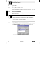
4.2
Starting the program
Select ProgramsWLenzeWGlobal Drive ControlWGlobal Drive Control.
· After the first program start, the dialog box Search drives is displayed for the selected port. You
can search here online for drives or change to the offline mode.
Abb. 7
Dialog box "Search drives" for Lecom−A/B or system bus (CAN)
Button
Function/Notes
Search
Searches for target systems connected to this port and starts GDC in online mode.
^ 43
Cancel
Closes the dialog box and starts GDC in Online mode,
without searching for connected target systems.
^ 43
Offline
Closes the dialog box and starts GDC in Offline mode,
without searching for connected target systems.
^ 45
Help
Opens GDC online help with information on this dialog box.
Tip!
If you use a port other than the selected one:
1. Click the button Cancel, to close the dialog box Search drives .
2. Select OptionsWCommunication, to change communication settings.
3. Start a new search. (See next page)
For further information on communication settings refer to the GDC online help.
42
GDC DE/EN 4.0
L
Global Drive Control
4.3
Find target system (Online mode)
The dialog box Find drives is opened automatically when GDC is started in online mode.
· You can call the dialog box Find drives using one of the following possibilities:
– Press the function key F2
– Select DriveWFind.
– In the toolbar, click on the button
To search a drive you can enter different settings which are dependent on the port used: (see also
Abb. 7)
· Browse all baud rates: (only for Lecom−A/B)
Activate the check box to browse all baud rates from 1200 to 19200 baud.
· Quit search when drive found:
Activate the check box to cancel the search once a target system has been found.
· Search drives: (only for Lecom−A/B)
Activate the check box to include slave drives in your search.
· Drive addresses:
Enter the range of controller addresses which you want to find.
Click the button Search to start searching or click Cancel to abort.
Tip!
GDC automatically tries to allocate device descriptions to the target systems found.
· If only one target system was found and a device description could be allocated, the device
description is loaded immediately.
· If the automatic allocation to the device description fails a dialog box appears in which you can
select the suitable device description manually.
Further information on manual selection
– of a basic controller can be found in section 4.4. (^ 45)
– of an AIF module can be found in section 4.5. (^ 46)
– of FIF modules can be found in section 4.6. (^ 48)
L
GDC DE/EN 4.0
43
Global Drive Control
Window "Drives connected to bus"
All target systems found on or allocated to the target system including available AIF/FIF modules are
listed in the window Drives connected to bus.
· If the window should not appear select WindowWDrives connected to bus to show the
window.
Abb. 8
Window Drives connected to bus
Doubleclick the target system which you want to parameterize with GDC.
· The corresponding device description file will be loaded into GDC and the dialog for short
commissioning or the parameter window will be displayed.
– More information on the dialog for short commissioning can be found in section 4.7. (^ 50)
– More information on the parameter window can be found in section 4.8.6. (^ 56)
Tip!
If you click an entry with the right mousebutton a context menu with a command for manual allocation
of the device description file will appear.
With the context menu command:
· Manipulate basic controller you call the dialog box Assign device description to the basic
controller. (^ 45)
· Manipulate AIF you call the dialog box Assign AIF module to the basic controller . (^ 46)
· Manipulate FIF you call the dialog box Assign FIF module(s) to the basic controller . (^ 48)
44
GDC DE/EN 4.0
L
Global Drive Control
4.4
Select target system manually (offline mode)
Proceed as follows to select the target system manually in offline mode:
1. Call the dialog box Assign device description to the basic controller using one of the following
possibilities:
– Press the function key F3
– Select ControllerWSelect
– In the toolbar, click on the button
2. Select the basic controller from the list field Controller description from the list:
Abb. 9
List field Device description in the dialog box Assign device description to the basic controller
Dialog box icons and their meanings
Marks a non−selected entry.
· Click the icon to select this entry.
Marks a selected entry
· The box at the bottom display more information on this entry.
Marks an entry which contains further (hidden) entries.
· Click the icon to show the subordinated entries.
Marks an entry which contains further (shown) entries.
· Click the icon to hide the subordinated entries.
Dialog box buttons and their meanings
L
Next
Go on to the dialog box Assign AIF module to the basic controller.
Cancel
Cancels allocation, closes dialog box without accepting changes.
Find (path)
Loading a controller description file (*.pdb) via the PC file system.
· Open the dialog box Open the controller description file which you want to load into GDC.
Help
Calling the online help
GDC DE/EN 4.0
45
Global Drive Control
4.5
Assign AIF module to the basic controller
If an AIF module is connected to the basic controller and the PC ótarget system communication is
via this AIF module you can load the controller description assigned to the AIF module. This allows you
to parameterize the AIF module with GDC as well.
Automatic assignment in online mode
In the online mode, an available AIF module is identified automatically and listed in the window "Drives
connected to bus". (^ 55)
· By clicking with the right mousebutton on the AIF module entry the command Manipulate AIF
is available which you can call via the dialog box Assign AIF module to the basic controller (see
next paragraph "Manual assignment in offline mode).
Manual assignment in offline mode
In offline mode, you can assign the AIF module via the dialog box Assign AIF module to the basic
controller which you call with the button Next in the dialog box Assign device description to the basic
controller . (^ 45)
· Select the AIF module from the list field AIF module for ... from the list:
Abb. 10
list field AIF module for ... in the dialog box Assign AIF module to the basic controller
Tip!
If the PC is not connected to the basic controller via the AIF module interface
− or −
no AIF module is connected to the basic controller, select the entry "No AIF module/keypad".
46
GDC DE/EN 4.0
L
Global Drive Control
Dialog box icons and their meanings
Marks a non−selected entry.
· Click the icon to select this entry.
Marks a selected entry
· The box at the bottom display more information on this entry.
Marks an entry which contains further (hidden) entries.
· Click the icon to show the subordinated entries.
Marks an entry which contains further (shown) entries.
· Click the icon to hide the subordinated entries.
Dialog box buttons and their meanings
L
Back
Return to dialog box Assign device description to the basic controller.
Complete
Complete selected assignment.
· This button will appear only if the basic controller has no FIF interface otherwise the
button Next will be displayed.
Next
Go on to the dialog box Assign FIF module to the basic controller.
· This button will appear only if the basic controller has an FIF interface otherwise the
button Complete will be displayed.
Cancel
Cancels allocation, closes dialog box without accepting changes.
Help
Calling the online help
GDC DE/EN 4.0
47
Global Drive Control
4.6
Assign FIF module to the basic controller
If one or more FIF modules are connected to the basic controller you can load the corresponding
controller descriptions so that you can parameterize the FIF modules with GDC as well.
Automatic assignment in online mode
In the online mode, an available FIF module is identified automatically and appears in the dialog box
Assign FIF module to the basic controller as "selected".
· If a FIF module other than the automatically selected one should be connected to the basic
controller, you can assign the module manually.
(see next paragraph "Manual assignment in offline mode).
· By clicking the button Complete or Next you accept the selection.
Manual assignment in offline mode
In the offline mode, you can assign the FIF module via the dialog box Assign FIF module(s) to the basic
controller which you call with the button Next in the dialog box Assign AIF module to the basic controller
. (^ 46)
· Select the FIF module from the list field FIF module for ... from the list:
Abb. 11
List field FIF module for ... in the dialog box Assign FIF module to the basic controller
Tip!
· If no FIF module is connected to the basic controller, select the entry "No FIF module".
· If the basic controller has several FIF interfaces click the button Next to proceed with the
assignment of the other FIF modules.
48
GDC DE/EN 4.0
L
Global Drive Control
Dialog box icons and their meanings
Marks a non−selected entry.
· Click the icon to select this entry.
Marks a selected entry
· The box at the bottom display more information on this entry.
Marks an entry which contains further (hidden) entries.
· Click the icon to show the subordinated entries.
Marks an entry which contains further (shown) entries.
· Click the icon to hide the subordinated entries.
Dialog box buttons and their meanings
L
Back
Return to the previous dialog box.
Complete
Complete selected assignment.
Next
Go on to the dialog box Assign second FIF module to the basic controller.
· This button will appear only if the basic controller has several FIF interfaces otherwise
the button Complete will be displayed.
Cancel
Cancels allocation, closes dialog box without accepting changes.
Help
Calling the online help
GDC DE/EN 4.0
49
Global Drive Control
4.7
Short commissioning
After the controller description of the selected/found target system has been loaded into GDC the GDC
dialog Short commissioning automatically opens in the GDC presetting.
4.7.1
Examples of a short commissioning dialog
The functions in the GDC dialog Short commissioning are dependent on the target system and are
explained here using examples.
50
GDC DE/EN 4.0
L
Global Drive Control
Field Button
Function/Notes
Changes of the selected configuration settings
Help
Online help display
· With the button Help you can call the online help with deliberate information on
the corresponding dialog box from any dialog box.
· General information on the use of the Windows help can be found in your
Windows documentation.
Start
· Starts the target system
Stop
· Stops the target system
Diagnostics
Change to GDC dialog Diagnostics
· Display of monitoring configuration, operating time, error messages, etc.
Parameter menu
Closing the GDC dialog Short commissioning and display of the parameter menu
· For the use of the parameter menu see section 4.8, "The user interface of
Global Drive Control". ( ^ 52 )
Control
Change to GDC dialog Control
· This GDC dialog is used to commission the target system.
– in online mode only
– in online mode only
– in online mode only
For more information on the commissioning dialog refer to the online help of the target system.
L
GDC DE/EN 4.0
51
Global Drive Control
4.8
User interface of Global Drive Control
4.8.1
Main window
The main window is the actual GDC user window.
· All other windows are document windows which can only be displayed within this user window.
· Functions on the arrangement of the user windows can be found in the menu Window .
The GDC main window contains
· the main menu , (^ 53)
· the toolbar , (^ 54)
· the status bar , (^ 55)
· and the GDC working area ,
in which more GDC windows are displayed:
– the window "Drives connected to bus", (^ 55)
– the parameter window
, (^ 56)
– the monitor window, (^ 59)
52
GDC DE/EN 4.0
L
Global Drive Control
4.8.2
Main menu
Apart from frequently used functions which are accessible through the toolbar or the funtion keys, for
instance, the GDC main menu contains numerous special functions which are arranged in submenus
according to their functionality.
Depending on the selected target system and the selected mode (online/offline) a submenu may be
hidden or functions in this submenu appear grey. Grey functions cannot be called.
Submenu
Functions
Drive
·
·
·
·
Notes
^ 43, 45
Finde/Select/Start/Stop
Communication parameters
Stop GDC
Parameter set transfer
PC ó drive
· Load/Save/Print parameters
· Submenu is displayed in online
Function block
editor
· Special function block editor
· Submenu is displayed only when ^ 60
Oscilloscope
· Special oscilloscope functions
Drive
parameters
functions
^ Online help
mode only.
the function block editor is
activated.
· only 93xx controllers
· Submenu is displayed only when ^ 61
the oscilloscope is activated.
· only 93xx controllers
as from software version 2.x
Tool
· Call from user−defined tool from · In this submenu, you can
GDC
· Call from optional GDC
components (function block
editor, osciolloscope)
Options
Window
Help
L
·
·
·
·
Program presettings
^ Online help
implement external programs
which can be called directly
from GDC.
^ Online help
Window arrangement
Online help display
Program information
GDC DE/EN 4.0
53
Global Drive Control
4.8.3
Toolbar
The toolbar allows easy access to frequently used functions. As an alternative your can use the function
keys of your PC keyboard for many functions.
Button
activated
Button
deactivated
Function key/Function
F1
Display of context−sensitive help
Close drive window.
54
F2
Search target system (online mode).
^ 43
F3
Select target system (offline mode).
^ 45
F4
Toggle between online and offline mode
^ 43
^ 45
F5
Transmit parameter set from PC to target system.
· in online mode only
F6
Transmit marked parameter from target system to PC.
· in online mode only
F7
Transmit parameter from target system to PC.
· in online mode only
F8
Start target system.
· in online mode only
F9
Stop target system.
· in online mode only
Start function block editor.
· only 93xx controllers
^ 60
Start oscilloscope function.
· only for 93xx servo controllers as from software version 2.0
and 93xx vector as from software version 1.0
^ 61
Start input assistent for motor data.
^ 62
GDC DE/EN 4.0
L
Global Drive Control
4.8.4
Status bar
Displayed information in the status bar
Information on controller−specific
IMP: Pulse inhibit set in target system
parameter menus
/ Status information of drive−specific dialogs
TRIP: Error in target system
RSP: Controller inhibit set in target system
Current mode (online/offline)
Online address (CAN or LECOM−A/B)
Active parameter set (in onlinel mode for 8200
vector/motec only)
4.8.5
Window "Drives connected to bus"
The window Drives connected to bus lists all available target systems including AIF/FIF modules.
· Doubleclick the target system which you want to parameterize in this window.
Abb. 12
Window Drives connected to bus
· For information on manual target system assignment refer to page 44ff. (^ 44)
L
GDC DE/EN 4.0
55
Global Drive Control
4.8.6
Parameter window
After the corresponding device description for a target system has been loaded into GDC the parameter
window is available.
· In this window you can easily enter all drive system−specific settings of the target system.
The parameter window is divided into two areas:
· The parameter menu is on the left−hand side where you select the menu item which you want
to parameterize.
· The right−hand side shows the parameters of the menu item activated in the parameter menu.
In the above example, these are the parameters for speed operation.
Icons in the parameter menu and their meanings
Parameter menu item, not selected.
· Doubleclick the icon to call the menu item.
Parameter menu item containing more submenu items. The submenu items are hidden.
· Doubleclick the icon to show the submenu item.
Parameter menu item containing more submenu items. The submenu items are shown.
· Doubleclick the icon to hide the submenu item.
Parameter menu item, selected.
· The right−hand side of the parameter window shows outputs of this activated menu item.
· Menu items starting with "Dialog" a GDC dialog is opened instead.
– Click the button Back or Parameter menu to close this GDC dialog.
Selecting parameters
You can select a target system parameter shown on the right−hand side in the parameter window using
the right mousebutton or the arrow keys.
· The selected parameter is highlighted by a yellow background.
· By pressing the function key F1 you open the online help with information on the selected
parameter.
56
GDC DE/EN 4.0
L
Global Drive Control
Changing parameters
You change a selected parameter through an input dialog which you open by pressing the Enter key.
Tip!
Use the left mousebutton to simultaneously a select parameter and open the input dialog to change
the parameter.
More information on the input dialogs can be found in the following section. (^ 58)
Codes/Objects
Parameters either have codes or objects:
· Codes are marked by a "C" in the column "Code" and represent the known Lenze codes.
· Objects are marked by a preceeding "I" in the column "Code" and represent parameters with a
hexadecimal address.
L
GDC DE/EN 4.0
57
Global Drive Control
4.8.7
Input dialogs
All input dialogs have the following four buttons:
Ok
The selected/entered value is accepted, the input dialog is completed.
· In online mode the value is transferred to the target system.*
Acceptance
The selected/entered value is accepted, the input dialog remains open.
· In online mode the value is transferred to the target system.*
Cancel
The input dialog is completed without accepting changes.
· Exception: The changes were already accepted by clicking the button Acceptance .
Help
The online help with information on the selected parameter is opened.
* Some parameters can only be changed in online mode if the controller has been inhibited in the target system.
The representation of the parameter value depends on the type of parameter:
Selection (list)
You can select a new setting for the
selected parameter from a list.
· The currently set value is selected in
the list when the input dialog is
opened.
Bit−coded
The parameter value is bit−coded.
· All bits and their meanings are listed.
· You can toggle between 0 and 1 with
the left mousebutton or the space bar.
· Alternatively, you can enter the
parameter value either as a decimal
or hexadecimal value.
Decimal
You can enter the parameter value within
a displayed range with the keyboard.
· For some parameters, the input dialog
offers additionally the buttons Up and
Down to change the parameter value
in fixed increments.
58
GDC DE/EN 4.0
L
Global Drive Control
4.8.8
Monitor window
The monitor window displays values which are measured cyclically by the controller.
· The monitor window is active only in online mode.
· In offline mode the monitor window is minimized automatically as an icon.
· Click one of the individual windows with the left mousebutton to enlarge this window. A second
mouseclick returns to the previous view.
· Click one of the individual windows with the right mousebutton to open the dialog box Monitor
configuration for the configuration of this window:
· Now you can perform the settings for the display with the blue background in the Monitor box
or by clicking another display in the Monitor box change to the settings of this display.
L
GDC DE/EN 4.0
59
Global Drive Control
4.9
Function block editor
The function block editor is a powerful tool for the generation, diagnostics and analysis of signal
configurations in Lenze 93xx controllers.
· In the toolbar, click the button
, to open the dialog box Function block editor.
Signal configuration generation
Function block links can either be inserted or removed using the cursor. Function block parameters (e.g.
acceleration ramp or maximum speed) can be set with the function block editor.
Signal configuration diagnostics
At the function block inputs and outputs, actual values can be shown which are updated cyclically. With
a mouseclick these signals can be traced through the function blocks to find errors in the signal flow.
The function block editor also supplies information on the processing sequence of the individual function
blocks.
Signal configuration analysis
Every function block which is used in the signal configuration can be displayed graphically. Individual
signals (e.g. speed setpoint) can be traced throughout the entire signal configuration using the cursor.
The function block parameters show their correspoding function.
More information on the function block editor can be found in the
menu Help WFunction block editor .
60
GDC DE/EN 4.0
L
Global Drive Control
4.10
Oscilloscope function
GDC offers an oscilloscope function for 93xx servo controllers as from software version .20 (93xx vector
as from software version 1.0).
· In the toolbar, click the button
, to open the dialog box Oscilloscope .
The oscilloscope function is used to measure any signals which are processed by the controller. For
this purpose the controller includes a function block (OSZ) which works like a memory oscilloscope.
This function block can measure and record up to four analog signals simultaneously. It is triggered
either via an additional digital input or one of the four analog channels.
The data is saved in the controller. Once a measurement is completed the data is transferred to the
PC and displayed using the oscilloscope function in GDC.
Controller and visualization function can communicate only via
· LECOM−A/B
· System bus
More information on the oscilloscope function can be found in the
menu Help WOscilloscope .
L
GDC DE/EN 4.0
61
Global Drive Control
4.11
Input assistent for motor data
The input assistent for motor data is used to select the motor used from a list of Lenze motors or a
user−defined list. The motor data is then transmitted to the target system.
You can add more motor types to the user motor list, either by directly entering the data or by loading
it from a file using the import function. The motor list can be exported to other computers with GDC
using the export function.
· In the toolbar, click the button
, to open the dialog box Input assistent for motor data .
The input assistent is divided into four areas:
Input dialog overview
Input dialog
Information on the motor type currently set in the target system
Information on the input dialog
62
GDC DE/EN 4.0
L
Global Drive Control
Input dialog overview
The input dialog overview shows you in which input step you are, which inputs have already been
completed and which inputs remain to be done:
· You can change to the input dialog by clicking an entry.
Input dialog
Make the suitable selection or entries in the input dialog.
Click the button
· Next to proceed with the next input step or Back to return to the previous input step.
· Complete to transmit the motor data of the selected motor to the target system.
· Cancel to cancel the input assistent for motor data and return to GDC.
· Help to call the GDC online help.
Information on the motor type currently set in the target system
In online mode, this area displays which motor type is currently selected in the target system and from
which motor list it has been taken.
· Click the button Update to read the set motor type again from the target system.
Information on the input dialog
This area displays additional information on the input dialog.
Tip!
More information on the input assistent for motor data can be found by clicking the button Help in the
context menu.
L
GDC DE/EN 4.0
63
Global Drive Control
5
Appendix
5.1
Using GDC as OPC client
GDC has an integrated interface for OPC (OLE for Process Control) and can thus access − as OPC client
− to bus servers supported by Lenze DriveServer.
5.1.1
Bus server configuration
Before configuring GDC as an OPC client, the appropriate bus server must be configured so that it is
available for selection in GDC.
· For details about configuring the bus server, please refer to the bus server documentation.
Tip!
· The DriveServer delivery package includes bus servers for the fieldbus systems LECOM and
system bus (CAN). A bus server for the MPI bus (bus server S7−MPI) is also available from
Lenze. (^ 67)
· For an overview of the bus servers supplied by Lenze and third−party manufacturers, please
refer to the DriveServer – Accessories" documentation.
5.1.2
Configuring GDC communication parameters
To enable GDC to communicate with the DriveServer via the OPC interface, the GDC communication
parameters have to be configured accordingly:
1. Go to OptionsWCommunication..., to open the dialog box Select communication driver :
– All communication drivers available are displayed in the list field.
64
GDC DE/EN 4.0
L
Global Drive Control
2. In the list field select the entry OPC and select the button Parameter..., to open the dialog box
OPC :
3. Use the input field Computer name to enter the PC name on which the bus server is installed.
– Click the button Network to select the corresponding computer from your network
environment.
– If the bus server is installed on the same computer as GDC, you can simply leave the input
field Computer name blank.
Tip!
When accessing a bus server via a network, please bear in mind that:
In order to protect a computer from unauthorised access, the default DCOM safety settings do not allow
OPC access. Check the DCOM settings for the bus server concerned and change them, if necessary.
For details, please refer to the DriveServer – Getting Started" documentation.
4. Click the button Refresh to update the list of available OPC servers.
Tip!
The program distinguishes between normal" OPC servers and OPC bus servers:
· Configuring OPC servers (Data Access 2.0) is usually a difficult and time−consuming process.
· OPC bus servers (DRIVECOM) have been optimised for use with GDC/DriveServer and therefore
require only a minimum configuration.
We therefore recommend the use of OPC servers that also display bus server features (presetting OPC
options: þ Bus server (DRIVECOM) ).
5. Use the list field Available OPC servers to select the suitable OPC server and close the dialog
box OPC with Ok.
6. Close the dialog box Select communication driver with Ok.
GDC configuration as an OPC client is now complete.
L
GDC DE/EN 4.0
65
Global Drive Control
5.1.3
Find OPC drives
Once GDC has been configured as an OPC client, you can search online to find the drives connected
to the OPC bus server:
1. If GDC is still in offline mode, click OptionsWOnline or press function key <F4> to change to
online mode.
2. Go to ControllerWSearch... or press function key <F2>, to open the dialog box Find OPC
drives :
3. Click the button Search to start searching or click Cancel to abort.
– Once the search is completed the controllers found are listed in the window "Drives
connected to bus".
Note!
· GDC automatically tries to allocate device descriptions to the drive controllers found.
– If only one drive was found and a device description could be allocated, the device
description is loaded immediately.
– If automatic allocation of the device description for a drive fails, the device description for
the drive can be allocated manually.
Select the corresponding controller in the window "Drives connected to bus" or click
ControllerWSelect... to open the dialog for manual allocation.
· Use the command ControllerWCommunication parameters... to display the OPC access path
(e.g. COM1.Device_01) in text field Access path of the dialog box Current drive.
66
GDC DE/EN 4.0
L
Global Drive Control
5.1.4
Using the bus server S7−MPI
When used together with the Bus server S7−MPI GDC can also be used to set parameters for target
systems networked via PROFIBUS−DP and controlled via a Siemens SIMATIC S7 PLC.
The following figure shows the architecture of such a system:
Global Drive Control
Bus server S7−MPI
MPI
Function block
Siemens SIMATIC S7
PROFIBUS−DP
· The GDC oscilloscope function is the only function that is not available via this communication
path.
L
GDC DE/EN 4.0
67
Global Drive Control
5.2
Interface converter for LECOM−B (RS485)
If the target system is to communicate via LECOM−B (RS485), an intelligent interface converter RS232
óRS485 is required which is able to automatically reverse the direction of communication. The Lenze
interface converter 2100 does not meet this requirement.
We therefore recommend the following product:
I−7520 isolated RS232 to RS485 converter
Supplier: Spectra Computersysteme GmbH
Humboldstraße 36
D−70771 Leinfelden/Echterdingen
5.3
Frequently asked questions and answers
Error
Cause
Remedy
Parameter set files
cannot be read.
You tried to read parameter set files which
were generated with the "Lemoc2"
DOS−program.
GDC uses another file format for the saving of drive
parameters.
Transmit the parameter set from the controller to the
PC and save it with GDC.
No communication with
the controller.
The PC system cable is wrong.
Check the wiring of the system cable.
(For the assignment of the system cable refer to the
GDC online help.)
Controller is switched off or LECOM−A/B
module 2102 has no power supply.
Connect power supply to controller and check the
connection to the controller.
In the case of external voltage supply at the terminals
39 and 59, check the voltage (see operating
instructions of the controller).
Incorrect COM port selected.
Set correct COM port via Options WCommunication
Interface parameters are set incorrectly.
You can change the interface parameters using the
Windows Control Panel:
· COM1: address 03F8, IRQ 4
· COM2: address 02F8, IRQ 3
The Windows configuration is incorrect.
Note: You cannot access the COM ports via
the Windows program "Terminal"
(Startup/Programs/Accessories), either.
Install Windows again or eliminate configuration errors
in the "System.ini" file.
GDC with system bus
Error
Cause
Remedy
GDC or Windows crash
Removing PC system bus module which
Windows is running.
Do not remove PC system bus module from the
interface or plug into the interface while Windows is
running.
68
GDC DE/EN 4.0
L
Q
© 12/2008
F
(
Ê
ü
Lenze Automation GmbH
Grünstraße 36
D−40667 Meerbusch
Germany
+49(0)21 32 /99 04−0
+49(0)21 32 /7 21 90
[email protected]
Service
Lenze Service GmbH
Breslauer Straße 3
D−32699 Extertal
Germany
(
Ê
008000/ 2446877 (24 h helpline)
+49(0)5154/ 82−11 12
[email protected]
www.Lenze.com
EDSGDC § .=>s § DE/EN § 4.0 § TD16
10
9
8
7
6
5
4
3
2
1