1
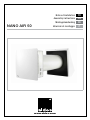
Notice d’installation
Assembly instructions
Montagehandleiding
NANO AIR 50
Istruzioni di montaggio
www.aldes.com
FR
GB
DE
IT
TABLE DES MATIÈRES • CONTENTS • INHALTSVERZEICHNIS • SOMMARIO
1. INTRODUCTION • INTRODUCTION • EINFÜHRUNG • INTRODUZIONE����������������������������������������4
2. GÉNÉRALITÉS • GENERAL INFORMATION • ALLGEMEINE INFORMATIONEN
• INFORMAZIONI GENERALI�������������������������������������������������������������������������������������������������������������5
2.1. Introduction
Introduction
Einführung
Introduzione��������������������������������������������������������������������������������������������������������������������������������5
2.2. C
onsignes de sécurité
Safety instructions
Sicherheitsvorschriften
Istruzioni di sicurezza������������������������������������������������������������������������������������������������������������������5
2.3. U
tilisation et Entretien
Use and Maintenance
Betrieb und Instandhaltung
Utilizzo e Manutenzione��������������������������������������������������������������������������������������������������������������6
3. CONTENU DU COLIS • DELIVERY SET • LIEFERUMFANG
• PRODOTTI FORNITI������������������������������������������������������������������������������������������������������������������������7
4. PRINCIPAUX PARAMÈTRES TECHNIQUES • MAIN TECHNICAL PARAMETERS
• TECHNISCHE GRUNDDATEN • PARAMETRI TECNICI PRINCIPALI���������������������������������������������������� 8
4.1. D
imensions générales du Nano Air 50, en mm
Nano Air 50 overall dimensions, mm
Aussenabmessungen der Nano Air 50, mm
Dimensioni di ingombro, mm������������������������������������������������������������������������������������������������������8
5. VUE DU NANO AIR 50 • NANO AIR 50 DESIGN • AUFBAU DER NANO AIR 50
• COMPONENTI NANO AIR 50��������������������������������������������������������������������������������������������������������10
5.1. M
odes de fonctionnement du Nano Air 50
Nano Air 50 operating modes
Betriebsarten der Nano Air 50
Modalità di funzionamento del Nano Air 50������������������������������������������������������������������������������13
6. MONTAGE ET PARAMÉTRAGE • MOUNTING AND SET-UP
• MONTAGE UND BETRIEBSVORBEREITUNG • MONTAGGIO E SET-UP������������������������������������14
6.1. M
ontage du Nano Air 50
Nano Air 50 mounting
Montage der Nano Air 50
Montaggio del Nano Air 50�������������������������������������������������������������������������������������������������������14
2
6.2. M
ontage de la grille extérieure
Ventilation hood mounting
Montage der lüftungshaube
Montaggio controvento esterno�����������������������������������������������������������������������������������������������18
7. RACCORDEMENT AU SECTEUR • CONNECTION TO POWER MAINS
• ANSCHLUSS AN STROMNETZ • CONNESSIONE ALLA RETE ELETTRICA������������������������������21
7.1. R
accordement de plusieurs Nano Air 50 en série
Connection of several Nano Air 50 in series
Hintereinanderschaltung von mehreren Nano Air 50
Collegamento di Nano Air 50 in serie���������������������������������������������������������������������������������������22
7.2. R
accordement de plusieurs Nano Air 50 en série (vue arrière)
Connection of several Nano Air 50 in series (backside view)
Serienverschaltung von mehreren Nano Air 50 (hintenansicht)
Collegamento di Nano Air 50 in serie (vista posteriore)������������������������������������������������������������23
7.3. R
accordement de plus de 10 Nano Air 50 en série
Connection of more than 10 Nano Air 50 in series
Hintereinanderschaltung von mehr als 10 Nano Air 50
Collegamento di più di 10 Nano Air 50 in serie������������������������������������������������������������������������24
8. COMMANDE DU NANO AIR 50 • NANO AIR 50 CONTROL
• STEUERUNG DER NANO AIR 50 • CONTROLLO NANO AIR 50�������������������������������������������������26
8.1. B
outons de commande sur le caisson du Nano Air 50
Control buttons on the Nano Air 50 casing
Steuertasten auf dem gehäuse
Pulsanti di controllo sul corpo del Nano Air 50������������������������������������������������������������������������26
8.2. Télécommande
Remote control
Fernbedienung
Telecomando����������������������������������������������������������������������������������������������������������������������������28
8.3. C
ommande par les boutons sur le caisson du Nano Air 50
Operation with the control buttons on the Nano Air 50 casing
Steuerung über die tasten auf dem Nano Air 50
Comandi sul corpo del Nano Air 50������������������������������������������������������������������������������������������29
8.4. Télécommande
Remote control
Fernsteuerung
Telecomando����������������������������������������������������������������������������������������������������������������������������30
9. ENTRETIEN • MAINTENANCE • WARTUNG • MANUTENZIONE��������������������������������������������������32
10. TABLEAU DE DÉPANNAGE • TROUBLESHOOTING • FEHLERBEHEBUNG
• RISOLUZIONE DEI PROBLEMI���������������������������������������������������������������������������������������������������36
11. RÈGLES DE STOCKAGE ET DE TRANSPORT • STORAGE AND TRANSPORTATION RULES
• LAGER- UND TRANSPORTVORSCHRIFTEN • REGOLE CONSEGNA E TRASPORTO�����������38
3
1. INTRODUCTION • INTRODUCTION • EINFÜHRUNG • INTRODUZIONE
FR
Ce manuel d’utilisation contient la description technique, les instructions d’utilisation, d’installation et de montage et les données
techniques du Nano Air 50 à récupération d’énergie.
GB
This user’s manual includes technical description, operation, installation and mounting guidelines, technical data for the energy
regeneration Nano Air 50.
DE
Die Betriebsanleitung enthält technische Grunddaten, technische Beschreibung, Montage- und Einbauanleitungen für die dezentrale reversierende Nano Air 50 mit Wärmerückgewinnung.
IT
Il presente manuale d’uso contiene descrizione tecnica, guida al funzionamento, istruzioni sull’installazione e specifiche tecniche
riguardanti il Nano Air 50.
4
2. GÉNÉRALITÉS • GENERAL INFORMATION • ALLGEMEINE
INFORMATIONEN • INFORMAZIONI GENERALI
2.1. Introduction • Introduction • Einführung • Introduzione
Nous vous remercions d’avoir choisi un produit ALDES. Nous vous recommandons de lire attentivement ce document et de suivre
les instructions afin de garantir le fonctionnement optimal de votre appareil. Notre responsabilité sur la qualité de fabrication ne
saurait être engagée au titre d’une mauvaise utilisation de l’appareil, d’une absence ou mauvais entretien de celui-ci, ou d’une
mauvaise installation de l’appareil. Dans un souci d’amélioration constante de la qualité de ses produits, la société ALDES se
réserve le droit de modifier à tout moment les caractéristiques indiquées dans ce document. Le bon fonctionnement de l’appareil
est conditionné par le strict respect de la présente notice. Le non-respect de ces préconisations pourrait supprimer le bénéfice de
la garantie.
FR
We would like to thank you for choosing an ALDES product. We recommend that you read this manual and follow the instructions
carefully in order to ensure that your unit works correctly. As the manufacturering quality we will not be responsible for any improper
use, poor maintenance or lack of maintenance of the unit, nor in the event of incorrect installation. In order to constantly improve
the quality of our products, ALDES reserves the right to modify the specifications included in this document at any time. The correct
operation of the unit depends on these instructions being followed carefully. Failure to follow these recommendations may void the
guarantee.
GB
Wir danken Ihnen dafür, ein ALDES-Produkt gewählt zu haben.Lesen Sie diese Anleitung aufmerksam durch und befolgen Sie die
Anweisungen, um den einwandfreien Betrieb Ihres Geräts zu gewährleisten. Wir haften nicht für eine unsachgemäße Benutzung
des Geräts, für mangelnde oder schlechte Instandhaltung desselben oder eine unsachgemäße Installation des Geräts. In dem
Bestreben, die Qualität der Produkte kontinuierlich zu verbessern, behält sich die Firma ALDES das Recht vor, die in diesem
Schriftstück angegebenen Merkmale jederzeit zu ändern.
DE
Vi ringraziamo per aver scelto un prodotto ALDES. Vi consigliamo vivamente di leggere il manuale e seguire attentamente le istruzioni per assicurare il corretto funzionamento del sistema. In qualità di fabbricante non rispondiamo in alcun modo di qualsiasi uso
improprio, cattiva o mancata manutenzione del sistema, o in caso di installazione errata. Con l’obiettivo di migliorare continuamente
la qualità dei nostri prodotti, ALDES si riserva il diritto di modificare in qualsiasi momento le specifiche contenute in questo documento.
IT
2.2. Consignes de sécurité • Safety instructions • Sicherheitsvorschriften • Istruzioni
di sicurezza
• La manutention et la mise en place de l’appareil doivent être adaptées au poids et à l’encombrement de ce dernier.
• L’appareil doit être placé à l’abri des intempéries et protégé du gel.
• L’appareil doit être positionné selon les prescriptions du fabricant.
FR
• The equipment should be handled and installed in accordance with its weight and dimensions.
• The unit should be installed in a dry place and should not be exposed to freezing temperatures (interior installations).
• The unit must be positioned as per the manufacturer’s recommendations.
GB
• Bei der Beförderung und beim Aufstellen des Geräts dessen Gewicht und Platzbedarf berücksichtigen.
• Das Gerät ist witterungs - und frostgeschützt aufzustellen.
• Die Anlage ist entsprechend den Herstellerempfehlungen aufzustellen.
DE
• L’apparecchio va maneggiato e installato tenendo conto del suo peso e delle dimensioni.
• La centrale va installata in un locale asciutto e al riparo dagli agenti atmosferici.
• La centrale va installata conformemente alle raccomandazioni del fabbricante.
IT
5
2.3. Utilisation et Entretien • Use and Maintenance • Betrieb und Instandhaltung
• Utilizzo e Manutenzione
FR
--En cas d’anomalie de fonctionnement, faire appel à un professionnel.
--Aucun obstacle ne doit entraver la circulation de l’air.
--Ne pas essayer de réparer votre appareil vous-même.
--Cet appareil ne contient aucune pièce susceptible d’être réparée par l’utilisateur lui-même.
--Couper l’alimentation électrique si des bruits anormaux, des odeurs ou des fumées proviennent de l’appareil et contacter
votre installateur.
--Avant tout nettoyage éventuel, couper l’alimentation électrique sur l’appareil.
--Ne pas utiliser de liquide de nettoyage agressif ou de solvants pour nettoyer l’appareil.
--Toute modification de l’appareil est interdite. Tout remplacement de composants doit être effectué par un professionnel avec
des pièces adaptées d’origine du constructeur.
GB
--Call a professional if a malfunction occurs.
--Nothing should block the circulation of air.
--Do not attempt to repair your unit yourself.
--Cut off the electrical power in the event of abnormal noises, smells or the presence of fumes and Contact your installation
technician.
--Cut the electrical power from the unit before attempting to clean it.
--Do not use an aggressive cleaning fluid or solvents to clean the unit.
--It is prohibited to modify the unit. Replacement of components must be performed by a qualified professional using original
spare parts supplied by the manufacturer.
DE
--Bei Funktionsstörungen an einen Fachmann wenden.
--Die Luftdurchströmung darf nicht behindert werden.
--Nicht versuchen, das Gerät selbst zu reparieren.
--Dieses Gerät enthält keine Teile, die vom Benutzer selbst repariert werden können.
--Durch das Abmontieren der Schutzverkleidung können Sie sich gefährlichen elektrischen Spannungen aussetzen.
--Die Stromzufuhr unterbrechen, sobald das Gerät anormale Geräusche von sich gibt oder es zu Geruchs- oder Rauchbildung
kommt, und Ihren Installateur kontaktieren
--Vor der Gerätereinigung die Stromversorgung immer unterbrechen.
--Die Anlage darf unter keinen Umständen verändert werden. Die Bauteile dürfen ausschließlich von qualifizierten Mitarbeitern,
und nur gegen Originalteile des Herstellers getauscht werden.
IT
--In caso di anomalia o malfunzionamento rivolgersi a personale qualificato.
--Il sistema di condotti dell’aria deve essere perfettamente sgombro.
--Non riparare la centrale da soli.
--Nessun particolare della centrale può essere riparato dall’utente.
--La rimozione di qualsiasi coperchio vi espone al pericolo di scariche elettriche.
--Interrompere immediatamente la corrente elettrica in caso di rumori anomali, odori o presenza di fumo e contattare il centro
assistenza Aldes.
--Prima di pulire la centrale togliere l’alimentazione elettrica.
6
3. CONTENU DU COLIS • DELIVERY SET • LIEFERUMFANG
• PRODOTTI FORNITI
Unité ventilation
1 unité
Jeu d’éléments de fixation
1 unité
Télécommande
1 unité
Manuel d’utilisation
1 unité
Carton d’emballage
1 unité
Ventilation unit
1 item
Fastening set
1 item
Remote control
1 item
User’s manual
1 item
Packing box
1 item
Ventilatoreinheit
1 st.
Befestigungsset
1 st.
Fernbedienung
1 st.
Betriebsanleitung
1 st.
Verpackung
1 st.
Ventilatore
1 articolo
Set di fissaggio
1 articolo
Telecomando
1 articolo
Manuale d’uso
1 articolo
Scatola di imballaggio
1 articolo
7
FR
GB
DE
IT
4. PRINCIPAUX PARAMÈTRES TECHNIQUES • MAIN TECHNICAL PARAMETERS
• TECHNISCHE GRUNDDATEN • PARAMETRI TECNICI PRINCIPALI
FR
Le Nano Air 50 est conçu pour une utilisation en intérieur, à une température ambiante comprise entre -20°C et +50°C, avec une
humidité relative jusqu’à 80%. Il est considéré comme un appareil électrique de classe I. Son indice de protection contre les corps
solides et liquides est IP24.
GB
The Nano Air 50 is designed for indoor application with the ambient temperature ranging from -20°C up to +50°C and relative humidity up to 80%. The Nano Air 50 is classified as a class I electric appliance. Ingress Protection (IP) rating from solid objects and
liquids IP 24.
DE
Die Nano Air 50 ist in einem geschlossenen Raum bei Temperaturen von -20°C bis zu +50°C und bei relativer Feuchtigkeit bis
höchstens 80% einsetzbar. Die Nano Air 50 gehört zu den elektrischen Nano Air 50 der Klasse I. Schutzart gegen Eindringen von
Fremdkörpern und Schutz gegen Wasser - IP24.
IT
Il Nano Air 50 è progettato per applicazione all’interno con una temperatura compresa tra i -20°C a +50°C e un umidità relativa
inferiore all’80%. Il Nano Air 50 è classificato come un apparecchio elettrico di classe 1. Grado di protezione IP 24.
4.1. Dimensions générales du Nano Air 50, en mm • Nano Air 50 overall dimensions, mm
• Aussenabmessungen der Nano Air 50, mm • Dimensioni di ingombro, mm
FR
Le Nano Air 50 est constitué du conduit télescopique, dont la longueur est définie par la position du conduit intérieur dans le
conduit extérieur, de l’unité de ventilation et de la grille extérieure. Le conduit intérieur contient deux filtres et l’accumulateur de
chaleur en céramique.
Les filtres purifient l’air insufflé et empêchent la pénétration de corps étrangers dans l’accumulateur de chaleur et le Nano Air 50.
Une alarme du Nano Air 50 rappelle tous les 90 jours qu’il est nécessaire de nettoyer ou de remplacer le filtre.
L’accumulateur de chaleur en céramique utilise l’énergie thermique de l’air extrait pour réchauffer le flux d’air insufflé. L’accumulateur de chaleur est équipé d’un cordon permettant de l’extraire facilement du Nano Air 50. Il est installé sur un matériau isolant
servant également de joint d’étanchéité.
L’unité de ventilation doit être installée sur la face intérieure du mur. Elle est équipée de volets automatiques condamnant le conduit
lorsque le Nano Air 50 est en veille, afin d’empêcher les retours d’air.
La grille extérieure doit être installée sur la face extérieure du mur afin d’empêcher la pénétration d’eau et d’autres corps dans le
Nano Air 50.
GB
The Nano Air 50 consists of the telescopic air duct with adjustable length regulated by position of the inner air duct inside the outer
air duct, the ventilation unit and the ventilation hood.
Two filters and the ceramic regenerator are located inside the inner duct of the telescope.
The filters are designed to purify supply air and prevent foreign object ingress to the regenerator and the fan.
The Nano Air 50 generates a sound alarm reminding to clean or replace the filter every 90 days.
The ceramic regenerator uses extract air heat energy to warm up supply air flow.
The regenerator is equipped with a pull cord inside to facilitate its withdrawal from the Nano Air 50. The regenerator is installed on
an insulation material used as a sealant as well.
The ventilation unit must be installed on inner side of the wall. The ventilation unit is equipped with automatic shutters that shut the
air duct off during the Nano Air 50 standby and prevent air back draft.
The ventilation hood must be installed on outer side of the wall to prevent ingress of water and other objects to the Nano Air 50.
DE
Die Nano Air 50 besteht aus dem längenverstellbaren Teleskopgehäuse, das sich von der Position des Innenteils im Aussenteil
regulieren lässt, der Nano Air 50 einheit und der Außenlüftungshaube.
Zwei Filter und ein Keramik-Wärmespeicher sind im Innenteil des Teleskopes installiert.
Die Filter dienen der Zuluftreinigung und verhindern Eindringen von Staub sowie Fremdkörpern in den Wärmespeicher und ins
Flügelrad.
Nach 90 Betriebstagen erfolgt ein Tonsignal, das auf den Filterwechsel oder die Filterreinigung deutet.
8
Der Keramik-Wärmespeicher übergibt die Abluftwärme an die frische Außenluft zur Erwärmung. Im Inneren des Wärmespeichers
befindet sich eine Zugschnur zum Herausziehen des Wärmespeichers aus der Nano Air 50. Der Wärmespeicher liegt auf einem
Dämmstoff, der auch als ein Dichtstoff dient. Die Nano Air 50 einheit ist von innen im Raum zu installieren.
Die Nano Air 50 einheit ist mit automatischen Jalousieklappen ausgestattet, die das Lüftungsrohr absperren, wenn die Nano Air 50
ausgeschaltet ist und verhindern somit den Luftrückstrom.
Die Lüftungshaube schützt die Nano Air 50 gegen Wasser- und Fremdkörpereindringung und ist auf der Außenseite des Gebäudes
zu installieren.
Il Nano Air 50 è composto da un canale telescopico per l’attraversamento della parete esterna e avente lunghezza regolabile.
Dall’unità di ventilazione e dal controvento esterno all’interno del canale sono presenti due filtri e il recuperatore di calore in ceramica.
I filtri sono predisposti per purificare l’aria immessa nella stanza e prevenire l’introduzione di polvere ed oggetti estranei nel recuperatore o nel Nano Air 50.
Ogni 90 giorni il Nano Air 50 emette un segnale acustico che indica la necessità di pulire o sostituire i filtri.
Il recuperatore in ceramica utilizza il calore dell’aria espulsa per riscaldare l’aria immessa.
Il recuperatore è facilmente estraibile per la pulizia e la manutenzione. Il recuperatore è installato su materiale coibente avente proprietà di isolamento termico, acustico ed elettrico.
Il Nano Air 50 deve essere installato sul lato interno della parete. E’ presente una griglia di ventilazione automatica che chiude il
canale quando il Nano Air 50 si spegne per evitare l’ingresso dell’aria.
Il controvento esterno deve essere montato sul lato esterno della parete per evitare l’ingresso di acqua ed altri oggetti estranei nel
Nano Air 50.
280
240
300
Ø 157
13
7
25
0
-4
70
86
Nano Air 50
9
IT
5. VUE DU NANO AIR 50 • NANO AIR 50 DESIGN • AUFBAU DER NANO AIR 50
• COMPONENTI NANO AIR 50
1
5
2
3
6
4
7
8
9
10
Nano Air 50
FR
1 – Conduit extérieur
Partie externe du conduit télescopique.
2 – Conduit intérieur
Partie interne du conduit télescopique.
3 – Plaque de montage
Plaque de montage permettant d’installer l’unité de ventilation au mur et de raccorder le Nano Air 50 au secteur.
4 – Unité de ventilation
Permet au Nano Air 50 de générer un flux d’air. La grille décorative protège le Nano Air 50 contre la pénétration de corps
étrangers. L’unité de ventilation est équipée de volets automatiques qui s’ouvrent quand le Nano Air 50 est en marche et se
ferment quand il est à l’arrêt, afin d’éviter le reflux d’air.
5 – Grille de ventilation extérieure
Interdit la pénétration d’eau et de corps étrangers directement dans le Nano Air 50.
6 – Bague d’écartement
Sert de support aux filtres et à l’accumulateur de chaleur dans le conduit intérieur.
7 – Filtre
Conçu pour purifier le flux d’air et empêcher la pénétration de poussière et de corps étrangers dans le Nano Air 50. Prévient
l’encrassement de l’accumulateur de chaleur.
8 – Accumulateur de chaleur en céramique
Récupère la chaleur de l’air extrait afin de réchauffer l’air insufflé.
9 – Filtre
Conçu pour purifier le flux d’air et empêcher la pénétration de poussière et de corps étrangers dans le Nano Air 50. Prévient
l’encrassement de l’accumulateur de chaleur.
10 – Redresseur de débit
Élimine les turbulences afin de réduire le niveau sonore.
10
1 – Outer air duct
Outer part of the telescopic air duct.
2 – Inner air duct
Inner part of the telescopic air duct.
3 – Mounting plate
A mounting plate for installation the ventilation unit on the wall and connecting the Nano Air 50 to the power mains.
4 – Ventilation unit
Is used to generate air flow by the fan. The decorative grille protects the fan against foreign objects ingress from the
premises. The ventilation unit is equipped with automatic shutters opening when the Nano Air 50 is on and closing when it is
off, thus preventing back air flow.
5 – Outer ventilation hood
Prevents direct water and foreign objects ingress to the Nano Air 50.
6 – Distance ring
Is used as a support for the filters and the regenerator in the inner air duct.
7 – Filter
Designed to purify supply air flow and prevent dust and foreign objects ingress to the Nano Air 50. Prevents regenerator
clogging.
8 – Ceramic regenerator
Provides extract air heat energy regeneration to warm up supply air flow.
9 – Filter
Designed to purify supply air flow and prevent dust and foreign objects ingress to the Nano Air 50. Prevents regenerator clogging.
10 – Air flow rectifier
Eliminates air turbulence, thus reducing noise level.
GB
1 – Äußerer Luftkanal
Außen liegender Teil des Teleskop-Luftkanals.
2 – Innerer Luftkanal
Inneren liegender Teil des Teleskop-Luftkanals.
3 – Montageplatte
Eine Montageplatte für die Installation des Gebläses an der Wand und zum Anschluss des Gebläses an die Stromversorgung.
4 – Gebläse
Für die Erzeugung des Luftstroms über den Nano Air 50. Das Deko-Gitter schützt den Nano Air 50 gegen das Eindringen von
Fremdkörpern aus dem Gebäude. Das Gebläse ist mit automatischen Klappen versehen, die sich öffnen, wenn der Nano Air
50 läuft, und die sich schließen, wenn er ausgeschaltet ist, um ein Rückströmen von Luft zu verhindern.
5 – Äußere Gebläseabdeckung
Verhindert das direkte Eindringen von Wasser und Fremdkörpern ins Gebläse.
6 – Abstandsring
Wird als Halterung für die Filter und den Regenerator im inneren Luftkanal verwendet.
7 – Filter
Dient der Reinigung von Zuluft und der Verhinderung des Eindringens von Staub und Fremdkörpern ins Gebläse. Verhindert
ein Verstopfen des Regenerators.
8 – Keramischer Regenerator
Dient der Wiedergewinnung von Wärmeenergie aus der Abluft, um die Zuluft zu erwärmen.
9 – Filter
Dient der Reinigung von Zuluft und der Verhinderung des Eindringens von Staub und Fremdkörpern ins Gebläse. Verhindert
ein Verstopfen des Regenerators.
10 – Luftstromrichter
Eliminiert Luftturbulenzen und reduziert so den Geräuschpegel.
DE
1 – Condotto esterno aria
Parte esterna del condotto telescopico dell’aria.
2 – Condotto interno aria
Parte interna del condotto telescopico dell’aria.
3 – Piastra di supporto
Piastra di supporto per installare a parete l’unità di ventilazione e collegare elettricamente il Nano Air 50.
4 – Unità di ventilazione
Genera il flusso d’aria tramite la ventola. La griglia estetica protegge la ventola dall’ingresso di oggetti estranei. L’unità di
ventilazione è dotata di serrande automatiche che si aprono quando il Nano Air 50 è in funzione e si chiudono quando è
spento, evitando così ingressi d’aria non desiderati.
IT
11
5 – Controvento esterno
Evita l’ingresso diretto di acqua o oggetti estranei nel Nano Air 50.
6 – Anello distanziale
Utilizzato come supporto per il filtri ed il recuperatore nel condotto interno.
7 – Filtri
Progettati in modo da purificare il flusso di aria in ingresso ed evitare che polvere ed oggetti estranei entrino nel Nano Air 50.
Evitano l’intasamento del recuperatore.
8 – Recuperatore ceramico
Recupera l’energia termica dall’aria estratta per riscaldare il flusso d’aria di rinnovo.
9 – Filtro
Progettato in modo da purificare il flusso di aria in ingresso ed evitare che polvere ed oggetti estranei entrino nel Nano Air 50.
Evita l’intasamento del recuperatore.
10 – Raddrizzatore del flusso d’aria
Elimina la turbolenza dell’aria riducendo così il livello di rumore acustico.
+20 °С
7
.
ec
0s
-7 °С
+20 °С
+17 °С
-7 °С
ec.
0s
-10 °С
7
2
CYCLE II • CYCLE II
• ZYKLUS II • CICLO II
+17 °С
-10 °С
FR
1–A
ir extrait
2–A
ir neuf
GB
1–A
ir extract
2 – Air supply
DE
1–A
bluft
2–Z
uluft
IT
1–A
ria estratta
2–A
ria immessa
1
CYCLE I • CYCLE I
• ZYKLUS I • CICLO I
12
5.1. Modes de fonctionnement du Nano Air 50 • Nano Air 50 operating modes • Betriebsarten
der Nano Air 50 • Modalità di funzionamento del Nano Air 50
Le Nano Air 50 présente quatre modes de fonctionnement :
• Alimentation d’air naturel - la pièce est ventilée de manière naturelle, le Nano Air 50 est à l’arrêt.
• Alimentation - le Nano Air 50 alimente le bâtiment en air neuf, quelle que soit la position du cavalier CN7.
• Ventilation - le Nano Air 50 fonctionne en mode alimentation permanente ou extraction à la vitesse paramétrée, selon la
position du cavalier CN7.
• Récupération - le Nano Air 50 fonctionne en mode double flux avec récupération de chaleur et d’humidité.
En mode Récupération, le Nano Air 50 fonctionne selon deux cycles de 70 secondes chacun.
Cycle I : l’air chaud vicié est extrait de la pièce. En traversant l’accumulateur de chaleur, il le réchauffe et l’humidifie. Jusqu’à 88%
de son énergie thermique est récupérée. Au bout de 70 secondes, l’accumulateur de chaleur en céramique est chaud et
le Nano Air 50 passe en mode Alimentation.
Cycle II : L’air neuf aspiré à l’extérieur traverse l’accumulateur de chaleur en céramique et absorbe la chaleur et l’humidité accumulées. Au bout de 70 secondes, l’accumulateur de chaleur en céramique a refroidi, le Nano Air 50 repasse en mode
Extraction et le cycle recommence.
FR
The Nano Air 50 has four ventilation modes :
• Natural air supply - the Nano Air 50 is used for natural ventilation, the fan is not activated.
• Supply - the Nano Air 50 supplies fresh air to the premise no matter of CN7 jumper position.
• Ventilation - the Nano Air 50 operates in permanent supply or extract mode at set speed depending on CN7 jumper position.
• Regeneration - the Nano Air 50 operates in reversible mode with heat and humidity regeneration.
In Regeneration mode the Nano Air 50 operates in two cycles, 70 seconds each.
Cycle I : Warm stale air is extracted from the room. As it flows through the regenerator, it heats and moisturizes the regenerator,
transferring up to 88% heat energy. In 70 seconds as the ceramic regenerator gets warmed the Nano Air 50 is switched
to supply mode.
Cycle II : Fresh intake air from outside flows through the ceramic regenerator and absorbs accumulated moisture and heat up to
the room temperature. In 70 seconds as the ceramic regenerator gets cooled down, the Nano Air 50 is switched into
extract mode and the cycle is renewed.
GB
Die Nano Air 50 hat vier Ventilationsbetriebsarten :
• Natürliche Zuluft - die Nano Air 50 wird für die natürliche Lüftung verwendet, der Nano Air 50 ist dabei aus.
• Zuluft - de Nano Air 50 sichert frische Luftzufuhr, unabhängig von der Position des Jumpers CN7.
• Belüftung - die Nano Air 50 funktioniert im permanenten Zu- und Abluftbetrieb bei der eingestellten Geschwindigkeit, je nach
der Position des Jumpers CN7.
• Regeneration - die Nano Air 50 funktioniert im reversiblen Betrieb mit Wärme- und Feuchterückgewinnung.
Im Regenerationsbetrieb funktioniert die Nano Air 50 in zwei Zyklen, je 70 Sekunden.
Zyklus I : Die warme Abluft wird dem Raum über den Keramik-Wärmespeicher entzogen. Die Abluft erwärmt und befeuchtet den
Wärmespeicher, dabei übergibt er bis zu 88% der Wärmeenergie. In 70 Sekunden wird der Wärmespeicher erwärmt und
die Nano Air 50 wechselt in den Zuluftbetrieb.
Zyklus II : Die frische Außenluft strömt über den Wärmespeicher und entnimmt die gespeicherte Wärme und Feuchte aus dem
Wärmespeicher, bis die Raumtemperatur erreicht wird. In 70 Sekunden wird der Wärmespeicher abgekühlt und die
Nano Air 50 wechselt wieder in den Abluftbetrieb. Der Zyklus startet neu.
DE
Il Nano Air 50 ha quattro modalità di ventilazione :
• Ventilazione naturale - il Nano Air 50 è utilizzato per la ventilazione naturale, non sono attivate altre funzioni.
• Immissione aria forzata - il Nano Air 50 assicura l’immissione dell’aria di rinnovo nel locale.
• Ventilazione - il Nano Air 50 effettua I’immissione o l’estrazione dell’aria alla velocità scelta.
• Recupero - il Nano Air 50 funziona in modalità reversibile con il recupero di calore e umidità.
In Modalità recupero il Nano Air 50 opera in due cicli, 70 secondi ciascuno.
Ciclo I : L’aria calda viene estratta dalla stanza, passa attraverso il recuperatore in ceramica e mentre scorre attraverso di esso
lo riscalda e umidifica con un trasferimento di calore pari al 88%. Quando il recuperatore viene riscaldato il Nano Air 50
passa al secondo ciclo.
Ciclo II : L’aria fresca dall’esterno passa attraverso il recuperatore, assorbe l’umidità e si riscalda fino alla temperatura ambiente
grazie al calore accumulato nel ciclo I. Quando la temperatura dell’accumulatore scende il Nano Air 50 passa in modalità
estrazione e ricomincia il ciclo I.
IT
13
6. MONTAGE ET PARAMÉTRAGE • MOUNTING AND SET-UP
• MONTAGE UND BETRIEBSVORBEREITUNG • MONTAGGIO E SET-UP
FR
GB
DE
IT
ATTENTION! Le Nano Air 50 doit être installé de manière à ce que le conduit d’air ne soit pas obstrué par des volets, rideaux,
voilages ou autres, afin de prévenir l’accumulation de poussière dans la pièce. Les rideaux peuvent par ailleurs affecter le flux
normal de l’air dans la pièce, rendant la ventilation inefficace.
CAUTION! The Nano Air 50 must not be installed in sites where the air duct may be clogged by the blinds, curtains, drapes,
etc. to prevent the room dust deposition and accumulation. Also, curtains might obstruct normal airflow in the room, thus rendering Nano Air 50 operation not efficient.
ACHTUNG! Zur staubverhinderung darf die Nano Air 50 nicht an den tellen montiert werden, wo das Lüftungsrohr durch
vorhänge, gardinen, portieren usw. Abgedeckt wird. Ausserdem können die vorhängen der normalen luftzirkulation im raum
behindern, damit wird der betrieb der Nano Air 50 uneffektiv.
ATTENZIONE! Il Nano Air 50 deve essere installato lontano da tende, tapparelle o persiane che possono ostacolare la circolazione dell’aria, rendendo inefficaci le prestazioni del Nano Air 50.
6.1. Montage du Nano Air 50 • Nano Air 50 mounting • Montage der Nano Air 50
• Montaggio del Nano Air 50
1.
FR
Un trou rond (170 mm) doit être percé dans le mur afin de monter le Nano Air 50.
GB
To mount the Nano Air 50 prepare a thorough round hole in the wall, 170 mm.
DE
Für die Montage der Nano Air 50 eine runde durchgehende Öffnung in der Außenwand vorbereiten, 170 mm.
IT
Per montare il Nano Air 50 preparare un foro circolare, 170 mm.
A
A-A
170
A
14
2.
FR
Une fois la traversée percée, découper un renfoncement de 25 mm de profondeur pour le passage des câbles et des prises de
contact raccordées à la plaque de montage. Si le montage de plusieurs Nano Air 50 en série est prévu, prévoir un renfoncement pour le passage des câbles lors du perçage de la traversée afin de permettre le raccordement desdits Nano Air 50.
GB
After preparing a through hole cut out a 25 mm deep recess for laying of the cables and the contact sockets connected to the
mounting plate. While mounting several connected in series Nano Air 50 provide a recess for the cable layout during the hole
preparation to enable series connection of several Nano Air 50.
DE
Nach der Vorbereitung der Wandöff nung einen Hohlraum zur Verlegung des Kabels und Schnittstellen zum Anschluss an
die Aufbauplatte in der Wand, 25 mm tief, ist einzuplanen. Bei der Montage mehreren hintereinander angeschlossenen Nano
Air 50 bei der Vorbereitung des Kabelschlitzes ist einen Hohlraum zur Verlegung des Kabels in der Wand zum Anschluss von
mehreren Nano Air 50 vorzubereiten.
IT
Dopo aver realizzato il foro sulla parete interna bisogna predisporre una rientranza profonda 25 mm per la posa dei cavi elettrici
collegati alla piastra di montaggio. Se si desidera collegare in serie più Nano Air 50 si consiglia, di provvedere alla realizzazione
della rientranza per mascherare il cavo nella parete.
max 90 mm
R100
15
4.
FR
Raccorder la plaque de montage. Percer quatre trous de fixation et fixer la plaque de montage au mur à l’aide de 4 vis 4x40 et
de chevilles 6x40 (fournies). Aligner le conduit télescopique sur la plaque de montage, puis combler les espaces entre le mur et
le conduit à l’aide de mousse expansive (non fournie). Le conduit télescopique ne doit pas dépasser de la surface de la plaque
de montage.
GB
Connect the mounting plate. Prepare four fastening holes and fix the mounting plate on the wall with fours 4x40 screws and
6x40 dowels (included into the delivery set). Align the telescopic air duct with respect to the mounting plate and fill the gaps
between the wall and the telescopic air duct with a mounting foam (not included). The telescopic air duct must not protrude
from the mounting plate surface.
DE
Die Aufbauplatte laut dem Schaltplan anschließen. Vier Befestigungslöcher bohren und die Aufbauplatte auf der Wand mit
vier Schrauben 4x40 und Dübeln 6x60 (in Lieferumfang enthalten) befestigen. Das Teleskoprohr bezogen auf die Aufbauplatte
zentrieren und die Hohlräume zwischen der Wand und dem Teleskoprohr mit einem Montageschaum füllen (nicht enchalteten).
Das Teleskoprohr muss bündig mit der Aufbauplatte sein.
IT
Collegare la piastra di montaggio. Preparare quattro fori di fissaggio e fissare la piastra al muro con quattro viti 4x40 e tasselli
6x60 (inclusi nella confezione). Allineare il condotto telescopico rispetto alla piastra e riempiere il vuoto tra il canale e il muro con
la schiuma di riempimento (non fornita). Il canale telescopico non deve sporgere al di fuori della piastra.
16
5.
6.
FR
Installer dans l’ordre le filtre, l’accumulateur de chaleur en céramique, un autre filtre et le redresseur de débit à l’intérieur du
conduit télescopique.
GB
Install the filter, the ceramic regenerator, another filter and the air flow rectifier in the consecutive order inside the telescopic air
duct.
DE
Den Filter, den keramischen Wärmespeicher, den anderen Filter und den Strömungsgleichrichter nacheinander in das Teleskoprohr installieren.
IT
Installare dentro al canale telescopico in ordine filtro, il recuperatore in ceramica, l’altro filtro e il raddrizzatore di flusso.
FR
Installer l’unité de ventilation sur la plaque de montage. L’unité de ventilation est fixée à l’aide d’aimants.
GB
Install the ventilation unit on the mounting plate. The ventilation unit is fixed with magnets.
DE
Die Nano Air 50 einheit auf der Aufbauplatte installieren. Die Nano Air 50 einheit wird mit Magneten fixiert.
IT
Instellare l’unità di ventilazione sulla piastra di montaggio. L’unità è fissata con dei magneti.
17
6.2. Montage de la grille extérieure • Ventilation hood mounting • Montage der lüftungshaube
• Montaggio controvento esterno
1.
FR
Marquer les trous de fixation de la grille extérieure, puis percer les trous destinés à recevoir les chevilles 6x40. Pour simplifier le
marquage, utiliser la partie arrière de la grille.
GB
Mark the fastening holes for the outer ventilation hood and drill holes for the dowel 6X40. For marking convenience use the
ventilation hood back part.
DE
Die Befestigungslöcher für die Montage der Außenlüftungshaube markieren und die Löcher für den Dübel 6x40 bohren. Für die
bequeme Markierung den hinteren Teil der Lüftungshaube benutzen.
IT
Effettuare una marcatura dei fori per fissare il controvento esterno, i fori dovranno essere delle dimensioni dei tasselli 6x40. Per
comodità usare per la marcatura la parte posteriore del coperchio.
220 mm
Ø6 mm
4 trous
4 holes
4 Löcher
4 fori
200 mm
2.
FR
Insérer les chevilles 6x40 (fournies) dans les trous.
GB
Insert the dowels 6X40 (included into the delivery set) into the holes.
DE
Die Dübel 6x40 (in Lieferumfang enthalten) in die Löcher einsetzen.
IT
Inserire i tasselli 6x40 (inclusi nella confezione) nei fori.
18
3.
4.
FR
Démonter la grille extérieure afin d’accéder aux trous de fixation.
GB
Disassemble the outer ventilation hood to enable access to the fastening holes.
Take off the upper part of the outer ventilation hood.
DE
Die Lüftungshaube ausbauen um einen Zugang an die Befestigungslöcher zu ermöglichen.
IT
Smontare il controvento esterno per consentire l’accesso ai fori di fissaggio.
FR
Fixer la partie arrière de la grille extérieure au mur à l’aide des vis 4x40 fournies.
GB
Fix the back part of the ventilation hood on the wall with 4X40 screws from the delivery set.
DE
Die Rückseite der Außenlüftungshaube an der Wand, mit den Schrauben 4X40 aus dem Liefersatz, befestigen.
IT
Fissare la parte posteriore del controvento esterno alla parete con viti 4x40 (incluse nella confezione).
19
5.
FR
Monter la partie supérieure de la grille extérieure.
GB
Mount the upper part of the ventilation hood.
DE
Den Vorderteil der Lüftungshaube aufsetzen.
IT
Montare la parte superiore del controvento esterno.
20
7. RACCORDEMENT AU SECTEUR • CONNECTION TO POWER MAINS
• ANSCHLUSS AN STROMNETZ • CONNESSIONE ALLA RETE ELETTRICA
ATTENTION! Débrancher le Nano Air 50 du secteur avant toute opération d’installation électrique. Raccorder le Nano Air 50
à une prise correctement installée équipée d’une borne de mise à la terre. Il est interdit de modifier les branchements internes.
Toute modification entraîne l’annulation de la garantie. Le Nano Air 50 est prévu pour être raccordé au secteur en 230 V monophasé. Afin de faciliter le câblage, le Nano Air 50 est fourni avec un cordon d’alimentation pré-câblé et une prise. Raccorder le
Nano Air 50 au secteur via le disjoncteur automatique à déclenchement magnétique intégré au circuit de câblage fixe.
CAUTION! Disconnect the Nano Air 50 from power mains prior to any electric installation operations. Connect the Nano Air 50
to a correct installed socket with a grounded terminal. Any internal connection modifications are not allowed and result in warranty loss. The Nano Air 50 is rated for connection to single-phase 230 V power mains. For wireworks facilitation, the Nano Air
50 is supplied with a pre-wired power cord and a plug. Connect the Nano Air 50 to power mains through the automatic circuit
breaker with magnetic trip integrated into the fixed wiring system.
ACHTUNG! Die Nano Air 50 vor allen arbeiten vom stromnetz trennen. Die Nano Air 50 muss an eine vorschriftsmässig installierte Steckdose mit einem geerdeten anschluss eingesteckt werden. Jeder eingriff in die internen anschlüsse ist verboten und
wird die garantie erlöschen lassen. Die Nano Air 50 ist für den anschluss an das einphasen-wechselstromnetz mit der spannung
von 230 V. Dafür ist ein stromkabel mit einem stecker, angeschlossen durch den hersteller, vorgesehen. Die Nano Air 50 über
einen externen netztrennschalter mit einem elektromagnetischem auslöser an das stromnetz anschließen.
ATTENZIONE! Prima di effettuare qualsiasi intervento il Nano Air 50 deve essere scollegato dalla rete elettrica. Il Nano Air 50
deve essere collegato ad una presa di corrente installata in modo appropriato, avente un contatto di messa a terra. Le eventuali
modifiche alla connessione interna sono proibite e comportano la perdita della garanzia. Il Nano Air 50 si collega alla rete di
alimentazione monofase 230 V. A questo scopo è previsto il cavo di alimentazione con spina collegato dal costruttore. Prevedere
una protezione con interruttore magnetotermico a monte del Nano Air 50.
21
FR
GB
DE
IT
7.1. Raccordement de plusieurs Nano Air 50 en série • Connection of several Nano Air 50 in
series • Hintereinanderschaltung von mehreren Nano Air 50 • Collegamento di Nano Air 50
in serie
Output
Input
Output
Input
L
G
L
G
L
G
L
G
D
N
D
N
D
N
Nano Air 1
Output
TO THE NEXT
VENTILATOR
Nano Air 2
Output
Input
L
G
L
G
D
N
Input
L
G
D
N
ground
terminal
D
N
L
G
D
N
ground
terminal
D
N
ground
terminal
ground
terminal
1~100-230 V
50-60 Hz
FR
Lorsque les Nano Air 50 sont raccordés en série, tous sont contrôlés par le premier Nano Air 50, à l’aide d’une télécommande
commune. Pour raccorder les Nano Air 50 en série, brancher la prise de contact de sortie de la plaque de montage du premier
Nano Air 50 à la prise de contact d’entrée de la plaque de montage du deuxième Nano Air 50.
Raccorder le deuxième Nano Air 50 au troisième de la même manière, et ainsi de suite. Au maximum, 10 Nano Air 50 peuvent être
raccordés en série.
Pour simplifier l’installation électrique, utiliser un câble à 5 fils (non fourni) de section supérieure à 0,5 mm².
Le câble doit être compatible avec une alimentation en courant alternatif à la tension secteur spécifique du pays d’installation. Le
câble d’alimentation doit être débranché pour raccorder les Nano Air 50 en série.
GB
When the Nano Air 50 are connected in series, all the connected Nano Air 50 are controlled with the first Nano Air 50 and a common remote control. To connect the Nano Air 50 in series connect the output contact socket of the first Nano Air 50 mounting
plate with the
Input contact socket of the second Nano Air 50 mounting plate.
Connect the second Nano Air 50 with the third Nano Air 50 in the same way, etc. Up to 10 Nano Air 50 may be connected in series.
For easy electric installations use a five-wire cable (not included into the delivery set) with the cable cross section not below 0.5
mm2.
The cable must be rated for operation in an alternating current power supply with the country-specific mains voltage. Disconnect
the power cord while connecting the second, third, etc. Nano Air 50 in series.
DE
Bei der Hintereinanderschaltung werden die mehreren verbundenen Nano Air 50 synchron über die erste Nano Air 50 und eine
gemeinsame Fernbedienung gesteuert. Zur Hintereinanderschaltung die Schnittstelle Output (Ausgang) auf der Aufbauplatte der
ersten Nano Air 50 an die Schnittstelle Input (Eingang) auf der Aufbauplatte der zweiten Nano Air 50 anschließen. Die zweite Nano
Air 50 mit der dritten Nano Air 50 in der gleichen Weise anschließen.
Bis zu 10 Nano Air 50 können hintereinander geschaltet werden. Elektrischer Anschluss erfolgt über ein Fünfleiterkabel (nicht mitgeliefert) mit dem Mindestkabelquerschnitt 0.5 mm2 für einfache Montage. Das Kabel soll für den Betrieb im Wechselstromnetz mit
der länderspezifi schen Nennspannung ausgelegt sein.
Beim Anschluss von der zweiten, dritten usw. Nano Air 50 das Netzkabel aus der Steckdose herausziehen.
22
Quando i Nano Air 50 sono comandati in serie vengono tutti comandati dal primo Nano Air 50 e da un unico telecomando. Nel
caso di collegamenti in serie è necessario collegare il contatto di Uscita sulla piastra del primo Nano Air 50 con il contatto di Entrata
sulla piastra del secondo Nano Air 50. Collegare il secondo Nano Air 50 con il terzo nello stesso modo. Si possono collegare in
serie fino a 10 Nano Air 50.
Per il collegamento si usa un cavo a cinque fili (non incluso), avente sezione di filo non inferiore a 0.5 mm2.
Il cavo deve essere compatibile con la rete in corrente alternata prevista. Durante il collegamenti in serie scollegare sempre i cavi
di alimentazione elettrica.
IT
7.2. Raccordement de plusieurs Nano Air 50 en série (vue arrière) • Connection of several
Nano Air 50 in series (backside view) • Serienverschaltung von mehreren Nano Air 50
(hintenansicht) • Collegamento di Nano Air 50 in serie (vista posteriore)
+
N
CN7 TB2
1
2
3
4
5
6
L
G
D
+
N
CN7
Le premier Nano Air 50 contrôle tous les Nano Air 50 raccordés. Le cavalier entre les contacts 1 et 2 ou 2 et 3 du connecteur CN7
détermine le sens du flux en mode Ventilation.
Si le cavalier connecte les contacts 1 et 2, le mode Ventilation extrait l’air de la pièce. Il s’agit d’un réglage d’usine!
Si le cavalier connecte les contacts 2 et 3, le mode Ventilation insuffle l’air.
La position du cavalier à chaque branchement d’un Nano Air 50 en série détermine le sens de rotation en mode Ventilation et la
phase de fonctionnement en mode Récupération. Exemple : si le cavalier du premier Nano Air 50 relie les contacts 2 et 3 et celui
du deuxième Nano Air 50 les contacts 1 et 2, les Nano Air 50 fonctionnent dans des sens opposés en mode Récupération.
FR
The first Nano Air 50 controls all the connected Nano Air 50. The jumper between the contacts 1 and 2 or 2 and 3 of CN7 socket
connector determines a flow direction in Ventilation mode.
If the jumper connects the contacts 1 and 2, air is extracted from the room in Ventilation mode. This is a factory setting!
If the jumper connects the contacts 2 and 3, air is supplied in Ventilation mode.
The jumper position at each connection in series Nano Air 50 determines a rotation direction in Ventilation mode and an operating
phase in Regeneration mode. Example : if the jumper at the first Nano Air 50 connects the contacts 2 and 3 and the jumper at the
second Nano Air 50 connects the contacts 1 and 2, the Nano Air 50 operate in opposite directions in Regeneration mode.
GB
Die Steuerung aller verbundenen Nano Air 50 erfolgt über die erste Nano Air 50. Die Position des Jumpers zwischen den Kontakten
1 und 2 oder 2 und 3 der Schnittstelle CN7 bestimmt eine Luftstromrichtung im Belüftungsbetrieb.
Wenn der Jumper die Kontakte 1 und 2 verbindet, dann wird die Abluft dem Raum im Belüftungsbetrieb entzogen (standardmäßig).
Wenn der Jumper die Kontakte 2 und 3 verbindet, dann wird die Frischluft dem Raum im Belüftungsbetrieb zugeführt.
Die Position des Jumpers auf jeder angeschlossenen Nano Air 50 bestimmt die Luftstromrichtung im Belüftungsbetrieb sowie den
Ausgangsphase im Regenerationsbetrieb.
z.B., der Jumper der ersten Nano Air 50 verbindet die Kontakte 2 und 3 und der Jumper der zweiten Nano Air 50 verbindet die
Kontakte 1 und 2. Im Regenerationsbetrieb funktionieren die Nano Air 50 gegenläufig.
DE
23
IT
Il primo Nano Air 50 controlla tutti gli altri ad esso collegati. Il ponte tra i contatti 1 e 2 o 2 e 3 del morsetto CN7 determina la direzione del flusso in modalità Ventilazione.
Se il il ponte si trova tra i contatti 1 e 2 allora in modalità Ventilazione si avrà l’aspirazione dell’aria (funzione predefinita).
Se il ponte si trova tra i contatti 2 e 3 allora in Modalità ventilazione si avrà l’a usso dell’aria.
La posizione del ponte in ciascun Nano Air 50 collegato in serie determina un senso di rotazione nella Modalità di ventilazione
nonchè la fase di funzionamento.
Cioè, se il ponte del primo Nano Air 50 si trova tra i contatti 2 e 3 e nel secondo Nano Air 50 si trova tra i contatti 1 e 2, allora in
fase di Recupero i Nano Air 50 funzionano in fase opposta.
7.3. Raccordement de plus de 10 Nano Air 50 en série • Connection of more than 10 Nano Air
50 in series • Hintereinanderschaltung von mehr als 10 Nano Air 50 • Collegamento di più
di 10 Nano Air 50 in serie
FR
Si plus de 10 Nano Air 50 sont raccordés, le 11e Nano Air 50 (bornes L et N) est alimenté par le secteur et non par le Nano Air 50
précédent. Les signaux de commande G et D provenant du 10e Nano Air 50 sont transmis via le câble 2 × 0,5 mm². Les Nano Air
50 12 à 20 sont raccordés au Nano Air 50 11 de la même manière que les Nano Air 50 1 à 10. Tous les Nano Air 50 raccordés
sont commandés par le Nano Air 50 1.
ATTENTION! Tous les Nano Air 50 raccordés en série doivent être mis à la terre.
GB
In case of connection above 10 Nano Air 50 power is supplied to the 11th Nano Air 50 (L and N terminals) not from the previous
Nano Air 50 but from power mains. The control signals G and D from the 10th Nano Air 50 are transferred throught the cable 2 × 0,5
mm2. The Nano Air 50 no.12....20 are connected to the Nano Air 50 no.11 in the same way as the Nano Air 50 no.1...10. All the
connected Nano Air 50 are controlled with the Nano Air 50 no.1.
CAUTION! All the connected in series Nano Air 50 must be grounded.
DE
Bei dem Anschluss von mehr als 10 Nano Air 50, muss die Stromversorgung der Nano Air 50 no.11 (Klemmen L und N) nicht über
die vorangehende Nano Air 50, sondern über ein Stromnetz zugeführt werden. Die Steuersignale G und D aus der Nano Air 50
no.10 werden über das Kabel 2 × 0.5 mm2 übertragen werden. Die Nano Air 50 no.12…20 an der Nano Air 50 no.11 in der gleichen
Weise, wie die Nano Air 50 no.1…10 anschließen. Alle hintereinander angeschlossene Nano Air 50 werden über die Nano Air 50
no.1. gesteuert.
ACHTUNG! Sichere erdung für alle hintereinander angeschlossene Nano Air 50 ist zu gewährleisten.
IT
Nel caso di collegamento di più di 10 Nano Air 50, l’alimentazione elettrica (prese di terra L e N) dell’11ma unità non proviene
dall’unità precedente ma dalla rete di alimentazione. I segnali G e D arrivano dal 10mo Nano Air 50 con il cavo 2 × 0.5 mm2. I Nano
Air 50 n.12...20 si collegano al n.11 nello stesso modo fatto precedentemente dal n.1 al n.10.
Tutti i Nano Air 50 collegati sono comandati dal Nano Air 50 n.1.
ATTENZIONE! Tutti i Nano Air 50 collegati devono assolutamente essere messi a terra.
24
TO THE NEXT
VENTILATOR
D
N
D
N
L
G
D
N
L
G
Input
Output
1~100-230 V
50-60 Hz
D
N
Output
L
G
L
G
Input
Nano Air n°11
L
G
L
G
1~100-230 V
50-60 Hz
D
N
D
N
Output
Input
Nano Air n°1- 10
Raccordement en série de plus de 10 Nano Air 50 • Connection in series of above 10 Nano Air 50
• Hintereinanderschaltung von mehr als 10 Nano Air 50 • Connessione in serie di più di 10 Nano Air 50
25
8. COMMANDE DU NANO AIR 50 • NANO AIR 50 CONTROL • STEUERUNG
DER NANO AIR 50 • CONTROLLO NANO AIR 50
FR
Le Nano Air 50 est commandé par télécommande ou par les boutons situés sur le caisson. Les fonctions de ces boutons sont
limitées : elles permettent d’activer la deuxième et la troisième vitesse, ainsi que de régler trois des quatre modes de ventilation. La
télécommande offre des fonctionnalités bien plus nombreuses.
GB
The Nano Air 50 is operated with a remote control or the buttons on the Nano Air 50 casing. The operation buttons on the Nano Air
50 casing have limited functionality and include activating the second and third speed and setting three of four ventilation modes.
The remote control has wider control capabilities.
DE
Die Steuerung der Nano Air 50 erfolgt über eine Fernbedienung oder über die Tasten auf dem Gehäuse. Die Tasten auf dem
Gehäuse ermöglichen die Aktivierung der zweiten und der dritten Geschwindigkeit und die Einstellung von drei aus vier Belüftungsbetriebe. Die Fernbedienung hat erweiterte Steuerungsmöglichkeiten.
IT
Il Nano Air 50 può essere comandato con un telecomando oppure con i comandi direttamente sul corpo del Nano Air 50.
I pulsanti situati sul corpo del Nano Air 50 hanno funzioni limitate, possono attivare la seconda e terza velocità ed impostare tre delle
quattro modalità di ventilazione. Il telecomando ha più funzioni e comandi.
8.1. Boutons de commande sur le caisson du Nano Air 50 • Control buttons on the Nano Air 50
casing • Steuertasten auf dem gehäuse • Pulsanti di controllo sul corpo del Nano Air 50
1
2
3
4
5
6
26
1 – Troisième vitesse
Le Nano Air 50 fonctionne en débit maximal.
2 – Le Nano Air 50 est sur ARRÊT
Le Nano Air 50 ne fonctionne pas. Les volets sont fermés.
3 – Deuxième vitesse
Le Nano Air 50 fonctionne à 50% du débit maximal.
4 – Mode Ventilation
Tous les Nano Air 50 raccordés en série fonctionnent en mode Extraction ou Alimentation, suivant la position du cavalier
CN7. Le cavalier est réglé par défaut en mode Extraction.
5 – Mode Récupération
Le Nano Air 50 alterne toutes les 70 secondes entre les modes Alimentation et Extraction avec récupération de chaleur.
6 – Mode Alimentation
Tous les Nano Air 50 raccordés en série fonctionnent en mode Alimentation, quelle que soit la position du cavalier CN7.
FR
1 – Third speed
The Nano Air 50 operates with maximum air flow.
2 – The fan is OFF
The Nano Air 50 does not operate. The shutters are closed.
3 – Second speed
The Nano Air 50 operates with 50% air flow.
4 – Ventilation mode
All the connected in series Nano Air 50 operate either in extract or supply mode according to the CN7 jumper position. By
default the jumper is set to extract mode.
5 – Regeneration mode
In this mode the Nano Air 50 switches between supply and extract mode each 70 seconds with heat regeneration.
6 – Supply mode
All the connected in series Nano Air 50 operate in supply mode with no reference to the CN7 jumper position.
GB
1 – Dritte Geschwindigkeit
Die Nano Air 50 läuft mit der Höchstgeschwindigkeit.
2 – Die Nano Air 50 ist AUS
Die Nano Air 50 läuft nicht. Die Jalousieklappen sind geschlossen.
3 – Zweite Geschwindigkeit
Die Nano Air 50 läuft mit der Förderleistung 50%.
4 – Belüftungsbetrieb
Bei der Hintereinanderschaltung funktionieren die Nano Air 50 in Ab- oder Zuluftbetrieb je nach Position des Jumpers CN7.
Standarmäßig ist der Jumper in der Position «Abluftbetrieb» gestellt.
5 – Regenerationsbetrieb
In diesem Betrieb funktioniert die Nano Air 50 70 Sekunden in Zuluftbetrieb und dan 70 Sekunden in Abluftbetrieb. Dabei
wird die Wärmeenergie zurückgewonnen.
6 – Zuluftbetrieb
Bei der Hintereinanderschaltung funktionieren alle Nano Air 50 im Zuluftbetrieb unabhängig von der Position des Jumpers
CN7.
DE
1 – Terza velocità
Il Nano Air 50 funziona alla portata d’aria massima.
2 – Nano Air 50 OFF
Il Nano Air 50 è spento. La alette sono chiuse.
3 – Seconda velocità
Il Nano Air 50 funziona al 50% della portata d’aria.
4 – Modalità ventilazione
Il Nano Air 50 immette l’aria oppure estrae aria alla velocità scelta in funzione della posizione del ponte CN7.
5 – Modalità recupero
In questa modalità il Nano Air 50 effettua ogni 70 secondi un ciclo di immissione e di estrazione aria.
6 – Modalità immissione
Tutti i Nano Air 50 collegati in serie operano in modalità immissione aria a prescindere dalla posizione del ponte CN7.
IT
27
8.2. Télécommande • Remote control • Fernbedienung • Telecomando
1
2
3
4
6
5
7
8
FR
1 – Nano Air 50 MARCHE/ARRÊT
2 – Mode nuit
Le Nano Air 50 passe en première vitesse lorsque la lumière baisse en dessous d’un certain seuil.
3 – Modification vitesse
4 – Alimentation air naturel
Les volets sont ouverts, le Nano Air 50 est à l’arrêt.
5 – Ventilation
Le Nano Air 50 fonctionne en mode Extraction ou Alimentation à la vitesse sélectionnée, selon la position du cavalier CN7.
6 – Alimentation d’air
Le Nano Air 50 insuffle en continu de l’air neuf dans la pièce, quelle que soit la position du cavalier CN7.
7 – Récupération
Le Nano Air 50 alterne toutes les 70 secondes entre les modes Alimentation et Extraction avec récupération de chaleur.
8 – Réglage du seuil d’humidité
GB
1 – Nano Air 50 ON/OFF
2 – Night mode
The Nano Air 50 switches to the first speed when the light in the night is off.
3 – Speed changeover
4 – Natural air supply
The shutters are open, the fan is off.
5 – Ventilation
The Nano Air 50 operates either in extract or supply mode at selected speed depending on CN7 jumper position.
6 – Air supply
The Nano Air 50 continually supplies fresh air to the room no matter of CN7 jumper position.
7 – Regeneration
The Nano Air 50 switches between supply and extract mode each 70 seconds with heat regeneration.
8 – Humidity threshold setting
28
1 – Nano Air 50 Ein/Aus
2 – Nachtbetrieb
Die Nano Air 50 schaltet in die erste Geschwindigkeit, wenn das Licht in der Nacht aus ist.
3 – Auswahl der Geschwindigkeit
4 – Natürliche Zuluft
Die Jalousieklappen der Nano Air 50 sind geöffnet, der Nano Air 50 ist aus.
5 – Belüftung
Die Nano Air 50 funktioniert entweder im Ab- oder Zuluftbetrieb mit der gewählten Geschwindigkeit, je nach Position des
Jumpers CN7.
6 – Zuluftbetrieb
Die Nano Air 50 liefert ständig die frische Luft in den Raum unabhängig von der Position des Jumpers CN7.
7 – Regeneration
Die Nano Air 50 funktioniert 70 Sekunden in Zuluftbetrieb und dann 70 Sekunden in Abluftbetrieb. Dabei wird die
Wärmeenergie zurückgewonnen.
8 – Einstellung des Feuchtesollwerts
DE
1 – Nano Air 50 ON/OFF
2 – Modalità notte
Durante la notte, con l’illuminazione spenta, il Nano Air 50 passa alla velocità uno per fare meno rumore.
3 – Selettore velocità
4 – Ventilazione naturale
La alette sono aperte, il Nano Air 50 è spento.
5 – Ventilazione
Il Nano Air 50 immette o estrae aria alla velocità scelta a seconda della posizione del ponte CN7.
6 – Modalità immissione aria forzata
Il Nano Air 50 immette aria di rinnovo costantemente a prescindere dalla posizione del ponte CN7.
7 – Recupero
Ogni 70 secondi il Nano Air 50 passa dal ciclo I (estrazione) al ciclo II (immissione).
8 – Impostazione soglia di umidità
IT
8.3. Commande par les boutons sur le caisson du Nano Air 50 • Operation with the control
buttons on the Nano Air 50 casing • Steuerung über die tasten auf dem Nano Air 50
• Comandi sul corpo del Nano Air 50
FR
GB
1. Mise en MARCHE du Nano Air 50. Réglage de la vitesse de
fonctionnement.
1. Turning the Nano Air 50 ON. Setting operation speed.
Deuxième vitesse.
Second speed.
Troisième vitesse.
Third speed.
2. Mise à l’ARRÊT du Nano Air 50.
2. Turning the Nano Air 50 OFF.
Mise à l’ARRÊT du Nano Air 50.
Turning the Nano Air 50 OFF.
DE
IT
1. Einchalten der Nano Air 50. Einstellung
der Geschwindigkeit.
1. Accensione del Nano Air 50. Impostare velocità.
Zweite Geschwindigkeit.
Velocità due.
Dritte Geschwindigkeit.
Velocità tre.
2. Ausschalten der Nano Air 50.
2. Spegnimento del Nano Air 50 OFF.
Ausschalten der Nano Air 50.
Nano Air 50 spento OFF.
29
8.4. Télécommande • Remote control • Fernsteuerung • Telecomando
FR
GB
Mettre le commutateur de vitesse sur
et le commutateur de
mode de ventilation sur
pour autoriser la commande à distance
de la ventilation.
Set the speed switch to position
and the ventilation mode switch
to position
to enable remote control of the Nano Air 50.
1. Mise en marche/arrêt du Nano Air 50
1. Turning Nano Air 50 ON/OFF
Marche/arrêt
ON/OFF
2. Mode Nuit
2. Night mode
Marche/arrêt
ON/OFF
Si le mode Nuit est activé, le Nano Air 50 passe en première vitesse
pendant la nuit, en l’absence de lumière. L’activation du mode nuit est
confirmée par un long signal sonore. L’arrêt du mode nuit est confirmé
par un bref signal sonore.
If Night mode is activated, the Nano Air 50 switches to the fi rst
speed in the night, when the light is turned off. Activation of the night
mode is confi rmed by a long sound signal. Exiting the night mode is
confi rmed by a short sound signal.
3. Réglage de vitesse
3. Speed setting
Première vitesse.
First speed.
Deuxième vitesse.
Second speed.
Troisième vitesse.
Third speed.
4. Mode de fonctionnement
4. Operation mode
Mode Alimentation d’air naturel. La pièce est
ventilée de manière naturelle, le Nano Air 50 est à
l’arrêt.
Natural air supply mode. The room is ventilated in
the natural way, the fan is off.
Mode Alimentation d’air. L’air est insufflé dans la
pièce à une vitesse définie, quelle que soit la position
du cavalier CN7.
Air supply mode. Air is supplied to the room at a
set speed no matter of CN7 jumper.
Mode Ventilation. L’air est extrait (réglage d’usine)
ou insufflé à la vitesse sélectionnée. La position du
cavalier CN7 influence le fonctionnement de tous les
Nano Air 50 raccordés en série.
Ventilation mode. Air is extracted (factory setting)
or supplied at a selected speed. All the Nano Air 50
connected in series Nano Air 50 operate depending
on position of CN7 jumper.
Mode récupération. Le Nano Air 50 fonctionne 70
secondes en mode Alimentation, puis 70 secondes
en mode Extraction avec récupération de chaleur.
Regeneration mode. The Nano Air 50 operates
70 seconds in Supply mode and then 70 seconds in
Extract mode with heat regeneration.
5. Contrôle d’humidité. L’humidité peut être régulée uniquement
en mode Récupération.
5. Humidity control. Humidity control is possible only
in Regeneration mode.
Réglage du seuil d’humidité — 45%
Setting humidity threshold — 45%
Réglage du seuil d’humidité — 55%
Setting humidity threshold — 55%
Réglage du seuil d’humidité — 65%
Setting humidity threshold — 65%
LE CONTRÔLE D’HUMIDITÉ EST ACTIVABLE UNIQUEMENT
AVEC LA TÉLÉCOMMANDE!
HUMIDITY CONTROL MAY BE ACTIVATED WITH
THE REMOTE CONTROL ONLY!
30
DE
IT
Zur Aktivierung der Fernsteuerung den Drehzahlschalter auf dem Anlagengehäuse in die Position
bringen und den Betriebsartschalter
in die Position
.
Impostare l’interuttore di velocità su
e la modalità di ventilazione
su
in grado di consentire il controllo remoto del Nano Air 50.
1. Nano Air 50 Ein/Aus
1. Attivare Nano Air 50 ON/OFF
Ein/Aus
2. Nachtbetrieb
Acceso/Spento
2. Modalità Notte
Ein/Aus
Acceso/Spento
Wenn der Nachtbetrieb aktiv ist, schaltet die Nano Air 50 in die
erste Geschwindigkeit in der nacht, wenn das Licht ausgeschaltet
ist. Umschalten in den Nachtbetrieb wird mit dem langen Tonsignal
bestätigt. Verlassen des Nachtbetriebs wird mit einem kurzen Tonsignal bestätigt.
Se è attivata la modalità Notte, in assenza di luce il Nano Air 50
passa automaticamente alla velocità 1. L’attivazione della modalità
notturna è confermata da un lungo segnale acustico, la disattivazione
invece da uno breve.
3. Geschwindigkeitseinstellung
3. Impostazioni della velocità
Erste Geschwidigkeit.
Prima velocità.
Zweite Geschwindigkeit.
Seconda velocità.
Dritte Geschwindigkeit.
Terza velocità.
4. Betreibsarten
4. Modalità di funzionamento
Natürlicher Zuluftbetrieb. Der Raum wird auf
natürlichem Weg belüftet, der Nano Air 50 ist dabei
aus.
Modalità di ventilazione naturale. La stanza è
ventilata in maniera naturale, il Nano Air 50 è spento.
Zuluftbetrieb. Die frische Luft wird dem Raum
zugeführt, unabhängig von der Position des Jumpers
CN7.
Modalità immissione aria forzata. L’aria viene
immessa ad una velocità stabilita a prescindere dalla
posizione del ponte CN7.
Belüftungsbetrieb. Die Abluft wird entzogen oder
die frische Luft wird dem Raum zugeführt in der eingestellten Geschwindigkeit. Bei der Hintereinanderschaltung wird die Betriebsart der Nano Air 50 durch
die Position des Jumpers CN7 bestimmt.
Modalità ventilazione. L’aria viene estratta (impostazione di fabbrica) o immessa ad una velocità
selezionata. Tutti i Nano Air 50 collegati in serie funzionano a seconda della posizione del ponte CN7.
Regenerationsbetrieb. Die Nano Air 50 funktioniert 70 Sekunden in Zuluftbetrieb und dann 70
Sekunden in Abluftbetrieb. Dabei wird die Wärmeenergie zurückgewonnen.
Modalità recupero. Il Nano Air 50 funziona 70
secondi in modalità immissione e 70 secondi in modalità estrazione con recupero di calore.
5. Feuchtigkeitskontrolle. Die Feuchtigkeitskontrolle ist nur im
Regenartionsbetrieb möglich.
5. Controllo umidità. Il controllo umidità è possibile solo in modalità recupero.
Einstellung der Einschaltfeuchte — 45%
Impostazione soglia di umidità — 45%
Einstellung der Einschaltfeuchte — 55%
Impostazione soglia di umidità — 55%
Einstellung der Einschaltfeuchte — 65%
Impostazione soglia di umidità — 65%
FEUCHTIGKEITSKONTROLLE IST NUR ÜBER
DIE FERNBEDIENUNG MÖGLICH!
IL CONTROLLO DELL’UMIDITA PUO ESSERE ATTIVATO
SOLO CON IL TELECOMANDO!
31
9. ENTRETIEN • MAINTENANCE • WARTUNG • MANUTENZIONE
FR
ATTENTION! Débrancher l’alimentation du Nano Air 50 avant toute opération d’entretien.
L’entretien consiste à nettoyer régulièrement les surfaces du Nano Air 50 afin d’éliminer la poussière, ainsi qu’à nettoyer ou à remplacer les filtres.
GB
CAUTION! Disconnect the Nano Air 50 from power supply prior to any maintenance operations.
Maintenance of the Nano Air 50 means regular cleaning of the Nano Air 50 surfaces of dust and cleaning or replacement of the
filters.
DE
ACHTUNG! Vor der wartung die Nano Air 50 von der stromversorgung trennen.
Die Wartung der Nano Air 50 umfasst regelmäßige Reinigung der Anlagenoberfl ächen sowie Filterersatz oder Filterreinigung.
IT
ATTENZIONE! Prima di qualsiasi operazione di manutenzione togliere l’alimentazione elettrica dall’unità.
La manutenzione del Nano Air 50 consiste nella rimozione della polvere dalle superfici e nella pulizia / sostituzione dei filtri.
1. Entretien du ventilateur (une fois par an) • Fan maintenance (once per year) • Pflege des ventilators (järlich)
• Manutenzione ventola (una volta l’anno)
FR
Tirer le ventilateur pour l’extraire.
GB
Pull the ventilator to remove.
DE
Die Ventilatoreinheit herausziehen und entfernen.
IT
Rimuovere il ventilatore dalla piastra.
32
FR
Nettoyer les pales. Pour éliminer la poussière, utiliser une brosse
douce, un chiffon ou un aspirateur. Ne pas utiliser d’eau, de
détergents abrasifs, de solvants ou d’objets pointus. Les pales
doivent être nettoyées une fois par an.
GB
Clean the impeller blades. To remove dust use a soft brush, cloth or a vacuum cleaner. Do not use water, abrasive detergents,
solvents, sharp objects. The impeller blades must be cleaned
once in year.
DE
Die Flügelradschaufeln reinigen. Staub mit einer weichen Bürste,
einem trockenen weichen Tuch, einem Staubsauger entfernen.
Reinigung mit Wasser, einem scheuernden Reinigungsmittel,
scharfer Gegenständen oder Lösungsmittel ist nicht gestattet.
Die Flügelradschaufeln einmal pro Jahr reinigen.
IT
Pulire le pale del ventilatore. Per rimuovere la polvere utilizzare
una spazzola morbida o un panno. Non utilizzare acqua, detergenti, solventi. La pale del ventilatore vanno pulite almeno una
volta l’anno.
2. Entretien de l’accumulateur de chaleur et du filtre (4 fois par an) • Regenerator and filter maintenance (4 times per year)
• Pflege des Wärmespeichers und der Filter (viermal pro Jahr) • Manutenzione del recuperatore e dei filtri (4 volte l’anno)
FR
Déposer le redresseur de débit.
Retirer le filtre situé devant l’accumulateur de chaleur.
Tirer sur le cordon pour extraire l’accumulateur de chaleur du
conduit. Tirer doucement sur l’accumulateur de chaleur pour ne
pas l’endommager.
Retirer le filtre situé derrière l’accumulateur de chaleur.
GB
Remove the air flow rectifier.
Remove the filter in front of the regenerator.
Pull the regenerator cord to remove the regenerator from the air
duct. Be careful while pulling the regenerator to avoid its damage.
Remove the filter after the regenerator.
DE
Den Strömungsgleichrichter herausziehen. Den Filter vor dem
Wärmespeicher herausziehen. Die Zugschnur ziehen und den
Wärmespeicher aus dem Lüftungsrohr herausnehmen. Den
Wärmespeicher vorsichtig ziehen, so dass der nicht beschädigt
wird. Den Filter nach dem Wärmespeicher herausziehen.
IT
Rimuovere il raddrizzatore del flusso dell’aria.
Rimuovere il primo filtro.
Estrarre con la cordicella il recuperatore in ceramica.
Prestare attenzione a non danneggiare il recuperatore.
Rimuovere il secondo filtro.
33
FR
Après 90 jours de service, le ventilateur émet un signal sonore
rappelant de remplacer ou de nettoyer le filtre. Ce signal est
répété toutes les 5 minutes jusqu’à ce que l’entretien du filtre ait
été réalisé. Nettoyer les filtres, les laisser sécher puis les installer
à l’intérieur du conduit. L’utilisation d’un aspirateur est autorisée.
La durée de service du filtre est de 3 ans.
GB
Once a 90 day period of operation expires, the ventilator generates a sound signal as a reminder of the need to replace or
clean filter. The signal is repeated every 5 minutes until the filter
maintenance has been completed. Clean the filters, let those get
dry and install the dry filters inside the air duct. Vacuum cleaning
is allowed. The filter rated service life is 3 years.
DE
Nach 90 Betriebstagen erfolgt ein Tonsignal, der auf den
Filterwechsel oder die Filterreinigung deutet. Das Tonsignal
wiederholt sich alle 5 Minuten, bis die Filter ersetzt oder gereinigt
werden. Die Filter waschen und trocken lassen. Die trockenen Filter in das Lüftungsrohr installieren. Reinigung mit einem
Staubsauger ist zulässig. Die Filterlebensdauer beträgt 3 Jahre.
Für einen Ersatzfilter kontaktieren Sie Ihren Händler.
IT
Dopo 90 giorni il ventilatore genera un segnale sonoro per ricordare la necessità di sostituire o pulire il filtro. Il segnale viene ripetuto ogni 5 minuti fino a quando non viene effettuata la pulizia.
Pulire i filtri e rinserirli una volta asciutti all’interno del condotto
d’aria. Il filtro ha una durata di 3 anni.
Contattare il venditore per i filtri di ricambio.
FR
Des saletés peuvent s’accumuler sur l’accumulateur de chaleur,
même en cas d’entretien fréquent. L’accumulateur de chaleur
doit être nettoyé régulièrement afin de garantir un rendement
élevé d’échange thermique. Nettoyer l’accumulateur de chaleur
à l’aide d’un aspirateur au moins une fois par an.
GB
Even regular technical maintenance may not completely prevent
dirt accumulation on the regenerator assemblies. Subject the
regenerator to regular cleaning to ensure high heat exchange
efficiency. Clean the regenerator with a vacuum cleaner at least
once in a year.
DE
Auch bei regelmäßiger Wartung der Filter, können die Staubpartikel auf den Wärmespeicher gelangen. Der Wärmespeicher
bedarf regelmäßiger Reinigung zur Erhaltung der hohen Effizienz
des Wärmeaustausches. Den Wärmespeicher einmal pro Jahr,
mit einem Staubsauger reinigen.
IT
Anche sul recuperatore è possibile che si vada a depositare della
polvere o dello sporco. Sottoporre ad una regolare pulizia anche
il recuperatore garantisce il suo perfetto funzionamento. Pulire il
recuperatore con un aspirapolvere almeno una volta l’anno.
FR
Pour réinitialiser le compteur, installer les filtres et l’accumulateur de chaleur dans le ventilateur, puis maintenir le bouton ARRÊT
appuyé pendant 10 secondes, jusqu’à l’émission d’un long signal sonore.
GB
To reset the operating time meter indication, install the filters and the regenerator into the ventilator and then press and hold the
button OFF
for 10 secondes until a long sound signal.
DE
Für die Rücksetzung der Timeranzeige : nach der Einsetzung der Filter und des Wärmespeichers in die Lüftungsanlage den Knopf
OFF
drücken und 10 Sekunden festhalten, bis der lange Tonsignal ertönt.
IT
Per riprendere le funzioni classiche e interrompere la manutenzione inserire nel condotto il filtro, il recuperatore, l’altro filtro e infine il
raddrizzatore di flusso. Tenere premuto il tasto OFF
per 10 sec. fino a che non sentirete un segnale acustico prolungato.
34
3. E
ntretien de la grille extérieure (une fois par an) • Ventilation hood maintenance (once per year) • Pflege def luftungshaube
(jährlich) • Manutenzione controvento esterno di ventilazione (una volta l’anno)
FR
La grille extérieure peut être obstruée par des feuilles ou d’autres corps étrangers, ce qui risque d’impacter les performances de
l’unité. Contrôler la grille extérieure deux fois par an et la nettoyer aussi souvent que nécessaire. Pour cela, la démonter et procéder
au nettoyage de la grille et du conduit.
GB
The ventilation hood grill may get clogged with leaves and other objects which impairs the unit performance. Check the ventilation
hood twice per year and clean it as often as required. To clean the ventilation hood disassemble it, then clean the ventilation hood
and the air duct.
DE
Die Lüftungshaube kann mit Laub verstopft werden und somit wird die Förderleistung der Lüftungsanlage vermindert werden. Die
Lüftungshaube zweimal pro Jahr prüfen und bei Bedarf reinigen. Zur Reinigung der Lüftungshaube diese demontieren, danach die
Außenlüftungshaube und das Lüftungsrohr reinigen.
IT
Controllare il controvento esterno almeno due volte l’anno per assicurarsi che non si fermino al suo interno foglie o corpi estranei
che potrebbero danneggiare il ventilatore. Per la sua pulizia basta sfilare il coperchio esterno, quindi pulire il controvento esterno e il
condotto dell’aria.
35
10. TABLEAU DE DÉPANNAGE • TROUBLESHOOTING • FEHLERBEHEBUNG
• RISOLUZIONE DEI PROBLEMI
FR
Défaut
Le Nano Air 50 ne démarre pas.
Déclenchement automatique de l’interrupteur
dès la mise en service du Nano Air 50.
Faible débit d’air.
Le ventilateur émet des signaux sonores.
GB
Raisons possibles
Solution
Absence d’alimentation électrique.
Vérifier que le Nano Air 50 est correctement
raccordé au secteur et corriger si nécessaire.
Le moteur est bloqué, le ventilateur est
encrassé.
Mettre le Nano Air 50 hors tension. Débloquer
le moteur et désencrasser le ventilateur. Nettoyer les pales. Redémarrer le Nano Air 50.
Surtension causée par un court-circuit du
circuit électrique.
Mettre le Nano Air 50 hors tension. Contacter
un installateur.
Le ventilateur est en vitesse basse.
Régler une vitesse plus élevée.
Le filtre, le ventilateur ou l’accumulateur de
chaleur sont sales.
Nettoyer ou remplacer le filtre, nettoyer le
ventilateur et l’accumulateur de chaleur.
Le compteur de durée de service a atteint le
seuil de remplacement des filtres.
Effectuer l’entretien de l’accumulateur et des
filtres.
Le ventilateur est sale.
Nettoyer le ventilateur.
Haut niveau sonore, vibrations.
Les vis du caisson du ventilateur ou de la
grille extérieure sont desserrées.
Serrer les vis du ventilateur ou de la grille
extérieure.
Fault
Possible reasons
Fault handling
No power supply.
Make sure that the ventilator is properly
connected to the power mains and make any
corrections, if necessary.
Motor is jammed, the impeller are clogged.
Turn the Nano Air 50 off. Troubleshoot the
motor jam and the impeller clogging. Clean
the blades. Restart the ventilator.
Overcurrent resulted from short circuit in the
electric circuit.
Turn the ventilator off. Contact your installer.
Low set fan speed.
Set higher speed.
The filter, the fan or the regenerator are dirty.
Clean or replace the filter, clean the fan and
the regenerator.
The operating time meter for filter replacement is activated.
Do the regenerator and the filter maintenance.
The impeller is soiled.
Clean the impeller.
Loose screw connection of the ventilator
casing or the ventilation hood.
Tighten the screws of the ventilator or the
outer ventilation hood.
The fan does not start up during the ventilator
start-up.
Automatic switch tripping following the ventilator turning on.
Low air flow.
The ventilator generates sound signals.
High noise, vibration.
36
Fehler
Der Ventilator startet beim Einschalten der
Lüftungsanlage nicht.
Auslösung des Schutzschalters beim Start
der Lüftungsanlage
Niedriger Luftstrom
Tonsignale
Mögliche Gründe
Abhilfe
Keine Stromversorgung.
Überprüfen, dass die Stromversorgung
richtig angeschlossen ist, ansonsten einen
Anschlussfehler beseitigen.
Blockierter Motor, verschmutzte
Flüfelradschaufeln.
Die Lüftungsanlage ausschalten. Die
Blockierung des Motors abstellen. Die Flügelradschaufeln reinigen. Die Lüftungsanlage
neu starten.
Erhöhte Stromaufnahme infolge des
Kurzschlusses im Stromnetz.
Die Lüftungsanlage ausschalten. Mit dem
Kundendienst Kontakt aufnehmen
Niedrige eingestellte Geschwindigkeit des
Ventilators.
Eine höhere Geschwindigkeit einstellen.
Verschmutzter Filter, Ventilator oder Wärmespeicher.
Den Filter reinigen oder ersetzen; den Ventilator und den Wärmespeicher reinigen.
Betätigung des Stundenzählers.
Den Filter und den Wärmespeicher reinigen.
Verschmutztes Flügelrad.
Das Flügelrad reinigen.
Hohes Geräusch, Vibrationen
Lockere Schraubverbindung im Gehäuse
oder in der Lüftungshaube.
Die Schrauben an der Lüftungsanlage oder
an der Lüftungshaube ziehen.
Guasto
Possibile causa
Gestione dei guasti
Mancanza di alimentazione.
Assicurarsi che il ventilatore sia collegato
correttamente e provvedere se necessario.
Motore inceppato, girante sporca.
Togliere l’alimentazione elettrica. Sbloccare
il motore e pulire il ventilatore e le pale.
Riavviare il ventilatore.
Corto circuito elettrico.
Spegnere il ventilatore e contattare il servizio
clienti.
La ventola è impostata a bassa velocità.
Impostare une velocità più elevata.
Il filtro, il recuperatore o la ventola sono
sporchi.
Pulire ventola, recuperatore e filtri o sostituirli.
Si è attivato il timer per la sostituzione / pulizia
dei filtri.
Manutenzione del filtro e del recuperatore.
La girante è sporca.
Pulire la girante.
Viti allentate sull’unità interna o sul controvento esterno.
Serrare le viti.
Il ventilatore non si avviva.
L’interruttore magnetotermico interviene
all’accensione.
Bassa portata d’aria.
Il ventilatore genera segnali acustici.
Rumore elevato, vibrazioni.
37
DE
IT
11. RÈGLES DE STOCKAGE ET DE TRANSPORT • STORAGE AND
TRANSPORTATION RULES • LAGER- UND TRANSPORTVORSCHRIFTEN
• REGOLE CONSEGNA E TRASPORTO
FR
Entreposer le Nano Air 50 dans l’emballage d’origine fourni par le fabricant, dans une pièce sèche et ventilée, à une température comprise entre +5°C et +40°C. L’environnement de stockage ne doit pas contenir de vapeurs agressives ni de mélanges
chimiques susceptibles d’entraîner une corrosion ou une déformation de l’isolant et des joints. Pour les opérations de manutention
et de stockage, employer un dispositif de levage adapté afin d’éviter tout chute ou oscillation excessive, susceptible d’endommager le Nano Air 50. Respecter les exigences de manutention applicables à ce type de colis. Le transport est autorisé dans tout type
de véhicule, à condition que le Nano Air 50 soit protégé contre les dommages mécaniques et les intempéries. Éviter les chocs et
les coups pendant la manutention.
GB
Store the Nano Air 50 in the manufacturer’s original packaging box in a dry ventilated premise at the temperature from +5°C up
to +40°C. Storage environment must not contain aggressive vapours and chemical mixtures provoking corrosion, insulation and
sealing deformation. Use moist machinery for handling and storage operations to prevent the Nano Air 50 damage in consequence
of falling or excessive oscillation. Fulfil the handling requirements applicable freight type. Transportation with any vehicle type is
allowed provided that the Nano Air 50 is protected against mechanical and weather damage. Avoid any mechanical shocks and
strokes during handling operations.
DE
Die Nano Air 50 in der Originalverpackung in einem belüfteten Raum bei der Temperatur von +5°C bis zu +40°C. Dämpfe und
Fremdstoffe, die Korrosion verursachen und Anschluss-Abdichtungen beschädigen können, sind in der Luft nicht zulässig. Bei
Umschlagsarbeiten verwenden Sie Hebezeug zur Vorbeugung möglicher Schäden. Die Transporterfordernisse für diese Ladungsart sind zu erfüllen. Die Beförderung mit jeder Fahrzeugart ist zulässig unter der Bedingung, dass die Nano Air 50! Gegen mechanische Schäden und Witterungseinflüsse geschützt ist. Umschlagarbeiten sorgfältig durchführen, vor Stößen schützen.
IT
Conservare il Nano Air 50 nella scatola originale, in un locale asciutto e ventilato con una temperatura compresa tra i +5°C fino a
+40°C. Non conservare l’imballo in un locale dove nell’aria siano presenti vapori o sostanze che favoriscono la corrosione e il deterioramento. Utilizzare macchinari idonei per il sollevamento e il trasporto dei Nano Air 50 in modo da evitare cadute accidentali che
potrebbero danneggiare il Nano Air 50. Sono permessi trasporti con qualsiasi mezzo a condizione che il Nano Air 50 sia protetto
da urti e agenti atmosferici.
38
39
11022987 - A - 04-15 - Imprimé en France/Printed in France
www.aldes.com