1
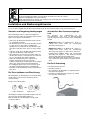
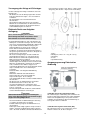
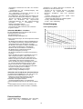
R
I-207Effective with the Serial Nuber:
LE Bester S.A.
ul. Jana III Sobieskiego 19 A
58-263 Bielawa
tel./074/ 64 61 100
fax /074/ 64 61 080
serwis: /074/ 64 61 188
http://www.bester.com.pl
e-mail: [email protected]
Process
MIG/MAG Welding
Description
D
C 1 3
P
h
as
e P
h
as
e
Semi-Automatic Welding Machines
operator’s manual / bedienungsanleitung / instrukcja obsługi
MiniMagster 1501, 1501S
July ‘2009
THANK YOU! For your appreciate of quality of LE Bester S.A. products.
•
Please check if the packaging and product aren’t damaged. The complaint of damage, which was accrued during
transportation must be submitted immediately for the deliverer (the distributor).
•
For convenience, please write the identification data of the product in this page, i.e. Model Name, Code and Serial
Number. You can find those date on the name plate of the product.
Wir Danken Ihnen! Für die Auswahl eins Qualitätsprodukts des LE Bester S.A. GmbH.
Prüfen Sie Bitte ob die Verpackung und die Einrichtung nicht beschädigt sind. Die Reklamationen der
Transportbeschädigungen sollen sofort an der Lieferant angemeldet werden.
Für Erleichterung schreiben Sie bitte auf diese Seite die identifizierungs- Daten. Modell Name, Code und
Seriennummer können Sie am Erzeugnisschild finden.
DZI KUJEMY! Za docenienie JAKO CI produktów LE Bester S.A.
•
Prosz sprawdzi czy opakowanie i sprz t nie s uszkodzone. Reklamacje uszkodze powstałych podczas
transportu musz by natychmiast zgłoszone do dostawcy (dystrybutora).
•
Dla ułatwienia prosimy o zapisanie na tej stronie danych identyfikacyjnych wyrobów. Nazwa modelu, Kod i Numer
Seryjny, które mo ecie Pa stwo znale na tabliczce znamionowej wyrobu.
Nie wyrzuca osprz tu elektrycznego razem z normalnymi odpadami!
Zgodnie z Dyrektyw Europejsk 2002/96/EC dotycz c Pozbywania si zu ytego Sprz tu Elektrycznego i
Elektronicznego (Waste Electrical and Electronic Equipment, WEEE) i jej wprowadzeniem w ycie zgodnie
z mi dzynarodowym prawem, zu yty sprz t elektryczny musi by składowany oddzielnie i specjalnie
utylizowany. Jako wła ciciel urz dze powiniene otrzyma informacje o zatwierdzonym systemie
składowania od naszego lokalnego przedstawiciela.
Stosuj c te wytyczne b dziesz chronił rodowisko i zdrowie człowieka!
Die elektrische Einrichtungen soll man nicht zusammen mit Haushaltmühle hinauswerfen!
Gemäß Europeische Direktive 2002/96/EC betrifft Gebrauchte Elektrische und Elektronische Einrichtungen
Loswerden (WEEE) und Sie in Benutzung, gemäß Internationale Recht, Einführung gebrauchte elektrische
Einrichtungen sollen getrennt lagern sein und speziell utilisiert. Als Einrichtungen Besitzer sollen Sie die
Auskunft über bestätigten Lagersystem von unserem Ortsverträter bekommen.
Diese Gesetze beobachten hilft Umwelt und Menschen Gesundheit Schutzen.
Do not dispose of electrical equipment together with normal waste!
In observance of European Directive 2002/96/EC on Waste Electrical and Electronic Equipment (WEEE)
and its implementation in accordance with national law, electrical equipment that has reached the end of its
life must be collected separately and returned to an environmentally compatible recycling facility. As the
owner of the equipment, you should get information on approved collection systems from our local
representative.
By applying this European Directive you will protect the environment and human health!
Model Name/ Modell Name/Nazwa modelu:
………………...…………………………….…………………………………………………………………………………………..
Code and Serial Number/ Code und Seriennummer/Kod i numer seryjny:
………………….……………………………………………….. …………………………………………………….……………..
Purches Date and Place/ Datum- und Platz des Ankaufes/Data i miejsce zakupu:
…………………………………………………………………... ……………………….…………………………………………..
3
Declaration of conformity
Konformitätserklärung
Deklaracja zgodno ci
LE BESTER S.A.
Declares that the welding machine:
Erklärt, daß die Bauart der Maschine:
Deklaruje, e spawalnicze ródło energii:
MiniMagster 1501, -1501S
s/n
conforms to the following directives:
den folgenden Bestimmungen entspricht:
spełnia nast puj ce wytyczne:
73/23/CEE, 93/68/CEE, 89/336/CEE, 92/31/CEE
and has been designed in conformance with the following norms:
und in Übereinstimmung mit den nachstehenden Normen hergestellt wurde:
i e zostało zaprojektowane zgodnie z wymaganiami nast puj cych norm:
EN 50199, EN 60974-1
Paweł Lipi ski
Operational Director
LE BESTER S.A., ul. Jana III Sobieskiego 19A, 58-260 Bielawa, Poland
4
07/09
ENGLISH INDEX
Safety .............................................................................................................................................................................. 6
Installation and Operator Instructions .............................................................................................................................. 7
Electromagnetic Compatibility (EMC) ............................................................................................................................ 11
Technical Specifications ................................................................................................................................................ 11
INHALTSVERZEICHNIS DEUTSCH
Sicherheitsmaßnahmen / Unfallschutz .......................................................................................................................... 12
Installation und Bedienungshinweise ............................................................................................................................. 13
Elektromagnetische Verträglichkeit (EMC) .................................................................................................................... 17
Technische Daten .......................................................................................................................................................... 17
SKOROWIDZ POLSKI
Bezpiecze stwo U ytkowania ....................................................................................................................................... 18
Instrukcja Instalacji i Eksploatacji .................................................................................................................................. 19
PrzepisyBHP...................................................................................................................................................................23
Kompatybilno Elektromagnetyczna (EMC) ................................................................................................................. 24
Dane Techniczne ........................................................................................................................................................... 24
Spare Parts, Ersatzteile, Wykaz Cz ci Zamiennych .................................................................................................... 25
Electrical Schematic, Elektrische Schaltpläne, Schemat Elektryczny ............................................................................ 30
Accessories, Zubehör, Akcesoria .................................................................................................................................. 32
5
Safety
07/09
WARNING
This equipment must be used by qualified personnel. Be sure that all installation, operation, maintenance and repair
procedures are performed only by qualified individuals. Read and understand this manual before operating this
equipment. Failure to follow the instructions in this manual could cause serious personal injury, loss of life, or damage to
this equipment. Read and understand the following explanations of the warning symbols. Lincoln Electric is not
responsible for damages caused by improper installation, improper care or abnormal operation.
WARNING: This symbol indicates that instructions must be followed to avoid serious personal injury,
loss of life, or damage to this equipment. Protect yourself and others from possible serious injury or
death.
READ AND UNDERSTAND INSTRUCTIONS: Read and understand this manual before operating
this equipment. Arc welding can be hazardous. Failure to follow the instructions in this manual could
cause serious personal injury, loss of life, or damage to this equipment.
ELECTRIC SHOCK CAN KILL: Welding equipment generates high voltages. Do not touch the
electrode, work clamp, or connected work pieces when this equipment is on. Insulate yourself from
the electrode, work clamp, and connected work pieces.
FUMES AND GASES CAN BE DANGEROUS: Welding may produce fumes and gases hazardous to
health. Avoid breathing these fumes and gases. To avoid these dangers the operator must use
enough ventilation or exhaust to keep fumes and gases away from the breathing zone.
ARC RAYS CAN BURN: Use a shield with the proper filter and cover plates to protect your eyes from
sparks and the rays of the arc when welding or observing. Use suitable clothing made from durable
flame-resistant material to protect you skin and that of your helpers. Protect other nearby personnel
with suitable, non-flammable screening and warn them not to watch the arc nor expose themselves to
the arc.
WELDING SPARKS CAN CAUSE FIRE OR EXPLOSION: Remove fire hazards from the welding
area and have a fire extinguisher readily available. Welding sparks and hot materials from the welding
process can easily go through small cracks and openings to adjacent areas. Do not weld on any
tanks, drums, containers, or material until the proper steps have been taken to insure that no
flammable or toxic vapors will be present. Never operate this equipment when flammable gases,
vapors or liquid combustibles are present.
ELECTRICALLY POWERED EQUIPMENT: Turn off input power using the disconnect switch at the
fuse box before working on this equipment. Ground this equipment in accordance with local electrical
regulations.
ELECTRICALLY POWERED EQUIPMENT: Regularly inspect the input, electrode, and work clamp
cables. If any insulation damage exists replace the cable immediately. Do not place the electrode
holder directly on the welding table or any other surface in contact with the work clamp to avoid the
risk of accidental arc ignition.
ELECTRIC AND MAGNETIC FIELDS MAY BE DANGEROUS: Electric current flowing through any
conductor creates electric and magnetic fields (EMF). EMF fields may interfere with some
pacemakers, and welders having a pacemaker should consult their physician before operating this
equipment.
NOISE APPEARES DURING WELDING CAN BE HARMFUL: Welding arc can cause noise with high
level of 85dB for 8-hour week day. Welders operating welding machines are obligated to wear the
proper ear protectors /appendix No. 2 for the Decree of the Secretary of Labor and Social Policy from
17.06 1998 – Dz.U. No. 79 pos. 513/. According to the Decree the Secretary of Health and Social
Welfare from 09.07.1996 /Dz.U. No. 68 pos. 194/, employers are obligated to carry examinations and
measurements of health harmful factors.
CYLINDER MAY EXPLODE IF DAMAGED: Use only compressed gas cylinders containing the
correct shielding gas for the process used and properly operating regulators designed for the gas and
pressure used. Always keep cylinders in an upright position securely chained to a fixed support. Do
not move or transport gas cylinders with the protection cap removed. Do not allow the electrode,
electrode holder, work clamp or any other electrically live part to touch a gas cylinder. Gas cylinders
must be located away from areas where they may be subjected to physical damage or the welding
process including sparks and heat sources.
6
WELDED MATERIALS CAN BURN: Welding generates a large amount of heat. Hot surfaces and
materials in work area can cause serious burns. Use gloves and pliers when touching or moving
materials in the work area.
CE COMPLIANCE: This equipment complies to the European Communities directives.
SAFETY MARK: This equipment is suitable for supplying power for welding operations carried out in
an environment with increased hazard of electric shock.
MOVING PARTS ARE DANGEROUS: There are moving mechanical parts in this machine, which can
cause serious injury. Keep your hands, body and clothing away from those parts during machine
starting, operating and servicing.
Installation and Operator Instructions
Read this entire section before installation or operation
of the machine.
Location and Environment
This machine will operate in harsh environments.
However, it is important that simple preventative
measures are followed to assure long life and reliable
operation.
Minutes
or decrease
Duty Cycle
Handle Fastening
• Do not place or operate this machine on a surface
with an incline greater than 15° from horizontal.
• This machine must be located where there is free
circulation of clean air without restrictions for air
movement to and from the air vents. Do not cover the
machine with paper, cloth or rags when switched on.
• Dirt and dust that can be drawn into the machine
should be kept to a minimum.
• This machine has a protection rating of IP21. Keep it
dry when possible and do not place it on wet ground
or in puddles.
• Locate the machine away from radio controlled
machinery. Normal operation may adversely affect
the operation of nearby radio controlled machinery,
which may result in injury or equipment damage.
Read the section on electromagnetic compatibility in
this manual.
• Do not operate in areas with an ambient temperature
greater than 40°C.
• Unpack the machine.
• Unpack the handle.
• Unscrew for screws fastening the top cover to the
chassis.
• Match the handle to the four holes on the top cover
and screw it with four screws.
Duty Cycle and Overheating
The duty cycle of a welding machine is the percentage
of time in a 10 minute cycle at which the welder can
operate the machine at rated welding current.
Input Supply Connection
Input connection of the welder and its grounding should
be done according to valid standards PN-E – 05009
“Electrical Installation in buildings”.
Example: 60% Duty Cycle:
MiniMagster 1501 is adopted to 1-phase, 3-wire
power supply network 230V, 50Hz protected with the
Superlag fuse 16 A.
Welding for 6 minutes.
MiniMagster 1501S is adopted to 1-phase, 3-wire
230V, 50 Hz power supply network, protected with the
Superlag fuse 16 A or to 3-phase, 5-wire 400V. 50
Hz power supply network protected with the Superlag
fuse 10 A. Power supply socket should have
naturalization terminal.
Break for 4 minutes.
Excessive extension of the duty cycle will cause the
thermal protection circuit to activate. See “Technical
Specification”.
7
MiniMagster 1501S is equipped with two input power
cords for two types of power supply. Change of the
power supply can be done by the power supply
switch, which is placed on the rear panel of the
welder.
the wire is cut by the drive roll or is locked in the guide
tube. Turning the thumbscrew to the right – pressure
increasing, turning the thumbscrew to the left –
pressure decreasing.
Before connecting the welder to the power supply
network , make sure if the main switch is “0” (switched
off).
Shielding Gas Connection
To connect shielding gas, you should:
After placing the shielding gas cylinder on the platform,
protect it against to overturn with the chain.
Take off the hub cap of the safety valve of the shielding
gas cylinder.
Install the regulator on the gas cylinder.
Connect the regulator to the MiniMagster with gas hose
using band clip.
Wire Loading
ATTENTION
Before wire loading, turn machine power switch to
the OFF (“0”) position before working inside the
wire feed enclosure.
To load wire you should do the following sequence of
operations:
Push the spool onto the spindle so that the wire
feeds off the bottom of the spool, toward the
drive roll.
Sleeve
Spool with wire: A - 5 kg, B - 0,5 kg
Spool spacer
Spring
Spool lock
5 kg spool push onto the shorter part of the spindle
with bigger diameter and 0,5 kg spool push onto the
longer part of the spindle with smaller diameter.
To lock the spool, push the spool spacer onto the
spindle. For 5 kg spool with the spool spacer flange
inward and for 0.5 kg spool with the spool spacer
flange outside.
Slide the spring onto the spool spacer, then press on
the spool lock, turning it clockwise to lock the spool
assembly onto the spindle.
Release the spring loaded thumbscrew and rotate the
idle roll arm away from the wire feed drive roll.
Ensure that the visible, stenciled size on the drive roll
side facing you matches the wire size being used.
Carefully detach the end of the wire from the spool
maintain tension on the wire to prevent the spool from
unwinding.
Thread the wire through the ingoing guide tube.
Thread the wire over the drive roll, and into the gun
liner.
Close the idle roll arm and turn down the thumbscrew
until the idle roller presses down firmly on the wire.
Remove the nozzle and contact tip from the gun.
Turn the machine ON (“I”).
Point the gun away so that outgoing wire doesn’t cut
the welder and other people standing nearby.
Depress the gun trigger switch and welding wire
should move towards the end of the gun.
Changing Polarity of the Output
Voltage
ATTENTION
Don’t look into the outlet of the gun during cold
inching - going out wire can seriously injure your
eye.
After going out the wire into the gun outlet (about 20
mm), release the gun trigger switch and twist the
contact tip suitable for the wire diameter being used.
Adjust pressure by turning thumbscrew. Pressure too
low – drive roll slips on the wire; pressure too high –
Welding with Positive Polarity (DC+)
As delivered the machine is wired for Positive Polarity.
To wire for Positive polarity, connect the gun cable to
the Positive (+) output terminal and the work cable to
the Negative (-) terminal.
Welding with Negative Polarity (DC-)
To wire for Negative Polarity, connect the gun cable to
8
the Negative (-) output terminal and the work cable to
the Positive (+) terminal. This is the typical
configuration for Flux Cored Welding (FCAW).
2.
Hose: For shielding gas connecting.
3.
Cooling Fun Holes: Don’t cover!
Controls and Operational Features of
the MiniMagster 1501 and 1501S
4.
Shelf: For placing the gas cylinder .
WARNING
After installation, protect the shielding gas cylinder
from overturn with the chain. Don’t place any gas
cylinder over 10 l – it can cause overturning the
welder.
Rear Panel of the MiniMagster 1501S
1.
Power Switch: Turns the machine on/off. Switching
on is indicated by lighting up of the switch button.
2.
WFS (Wire Feed Speed) Knob: 10-position scale
enables stepless WFS control in a range of 0 18.0m/min.
3.
Welding Voltage Changing Switche: enables four
values of welding voltage step selection: MIN1,
MIN2, MAX1 and MAX2.
WARNING
It is not allowed changing the welding voltage
range during welding process! It may damage
the switch.
4.
Thermal Protection Indicator: The lamp indicates
overheating of the machine.
5.
Welding Gun: Supplies welding voltage and
shielding gas and feeds electrode wire.
6.
Ground Cable with the Work Clamp.
1.
230V Input Power Cord with the Plug.
2.
400V Input Power Cord with the Plug.
3.
Hose: For shielding gas connecting.
4.
Cooling Fun Holes: Don’t cover!
5.
Shelf : For placing the gas cylinder .
WARNING
After installation, protect the shielding gas cylinder
from overturn with the chain. Don’t place gas cylinder over 10 l – it can cause overturning the
welder.
6.
Power Supply Change Switch
WARNING
It is not allowed changing the welding voltage
range during welding process! It may damage
the switch.
Rear Panel of the MiniMagster 1501
Final Actions
Connect the work cable to the work with the work
clamp.
Connect the gas cylinder to the gas input through the
gas regulator.
Insert the plug of the power input cord into the mains
power socket.
Switch on the welder with the power switch. Switching
on is indicated by lighting up of the power indicator.
Based on the seam kind, join type and material
thickness of the work piece, chose correct welding
settings with the welding voltage switch and WFS
control.
Obeying the appropriate regulations, you can begin to
weld.
1.
MIG/MAG Welding
Input Power Cord with the Plug.
The MIG/MAG Welding method requires adjusting only
two parameters:
9
- welding voltage
- electrode wire speed (WFS).
Below it was presented several recommendations,
which make easier to select welding parameters:
WFS increasing causes arc length shortening,
welding current increasing and joint penetration
increasing.
WFS decreasing causes arc length extension, welding
current decreasing and join penetration decreasing.
Welding voltage increasing causes arc length
extension.
Welding voltage decreasing causes arc length
shortening.
Too high WFS causes pushing up of the welding gun.
The electrode wire doesn’t keep up to melt into the
arc and it pushes away the gun.
Too low WFS or too high welding voltage creates big
drops on the end of the wire, which fall down beside
melted pool.
Too big splashing indicates too low welding voltage or
too high WFS.
Flux Cored Welding
To adopt welders MiniMagster 1501 and 1501S for Flux
Cored Welding, you should:
Mount the spool with flux cored wire onto the spindle.
Change the output voltage polarity in the wire feeder
chamber.
Put on the drive roll marked 0.9V/1.2V .
Match accessories of the welding gun for welding with
cored wire (contact tip140.D418 and nozzle
145.D258).
Spot Welding
Semiautomatic welders MiniMagster 1501 and 1501S
can be applied for spot welding – for welding thin parts
e.g. metal sheets.
To do it, you should:
Install the special gas nozzle for spot welding. It is
equipped with pins to pressure welded parts and it
provides free gas flow.
Set the welding settings according to the previous
discussed rules.
Welding time essentially influence on the joint quality:
- too long - causes too big metal penetration
- too short - joint lack.
Welding Process
10
Electromagnetic Compatibility (EMC)
07/09
This machine has been designed in accordance with all relative directives and norms. However, it may still generate
electromagnetic disturbances that can affect other systems like telecommunications (telephone, radio, and television) or
other safety systems. These disturbances can cause safety problems in the affected systems. Read and understand
this section to eliminate or reduce the amount of electromagnetic disturbance generated by this machine.
This machine has been designed to operate in an industrial area. To operate in a domestic area it is
necessary to observe particular precautions to eliminate possible electromagnetic disturbances. The
operator must install and operate this equipment as described in this manual. If any electromagnetic
disturbances are detected the operator must put in place corrective actions to eliminate these disturbances
with, if necessary, assistance from Lincoln Electric.
Before installing the machine, the operator must check the work area for any devices that may malfunction because of
electromagnetic disturbances. Consider the following.
•
Input and output cables, control cables, and telephone cables that are in or adjacent to the work area and the
machine.
•
Radio and/or television transmitters and receivers. Computers or computer controlled equipment.
•
Safety and control equipment for industrial processes. Equipment for calibration and measurement.
•
Personal medical devices like pacemakers and hearing aids.
•
Check the electromagnetic immunity for equipment operating in or near the work area. The operator must be sure
that all equipment in the area is compatible. This may require additional protection measures.
•
The dimensions of the work area to consider will depend on the construction of the area and other activities that are
taking place.
Consider the following guidelines to reduce electromagnetic emissions from the machine.
•
Connect the machine to the input supply according to this manual. If disturbances occur if may be necessary to take
additional precautions such as filtering the input supply.
•
The output cables should be kept as short as possible and should be positioned together. If possible connect the
work piece to ground in order to reduce the electromagnetic emissions. The operator must check that connecting
the work piece to ground does not cause problems or unsafe operating conditions for personnel and equipment.
•
Shielding of cables in the work area can reduce electromagnetic emissions. This may be necessary for special
applications.
Technical Specifications
MiniMagster 1501, 1501S
MiniMagster 1501
MiniMagster 1501S
INPUT PARAMETERS
Maximum Input
Input Voltage
Current
230V ±10%, 50 Hz
18.6 A
230V ±10%, 50 Hz
18.6 A
400V ±10%, 50 Hz
10.9 A
OUTPUT PARAMETERS
Duty Cycle
(Based on a 10 min. period)
X20 %
MiniMagster 1501
X60 %
X100 %
Maximum Power
Consumption
4.7 kVA
4.7 kVA
4.7 kVA
Power Factor
0.97
0.97
0.97
Output Current
Welding Current Range
Output Circuit
Voltage
115 A
65 A
50 A
40 - 115 A
19 – 32 V
(400 V)
(230V)
(400V)
(230V)
(400V)
115 A
MiniMagster 1501S
40 - 115 A
65 - 115 A
19 - 32 V 24 – 32 V
65 A
50 A
OTHER PARAMETERS
Degree
Insulation
Welding Voltage
Operating
WFS Range
Operating Humidity
Protection
Class
Steps
Temperature
IP21
H
0 - 18 m/min
4
od -10 do +40 C
90 %
RECOMMENDED FUSE SIZES
WEIGHT
Dimensions W x H x D
16 A Superlag
32 kg
MiniMagster 1501
365 x 383 x 635 mm
16 A (230V) /10 A (400V) Superlag
35 kg
MiniMagster 1501S
X20 %
X60 %
X100 %
(230 V)
115 A
65 A
50 A
11
Sicherheitsmaßnahmen / Unfallschutz
07/09
ACHTUNG
Diese Anlage darf nur von ausgebildeten Leuten benutzt, gewartet und repariert werden. Schließen Sie dieses Gerät
nicht an, arbeiten Sie nicht damit oder reparieren Sie es nicht, bevor Sie diese Betriebsanleitung gelesen und verstanden
haben. Bei Nichtbeachtung der Hinweise kann es zu gefährlichen Verletzungen bis hin zum Tod oder zu
Beschädigungen am Gerät kommen. Beachten Sie auch die folgenden Beschreibungen der Warnhinweise. Lincoln
Electric ist nicht verantwortlich für Fehler, die durch inkorrekte Installation, mangelnde Sorgfalt oder Fehlbenutzung des
Gerätes entstehen.
ACHTUNG: Dieses Symbol gibt an, dass die folgenden Hinweise beachtet werden müssen, um
gefährliche Verletzungen bis hin zum Tode oder Beschädigungen am Gerät zu verhindern. Schützen
Sie sich und andere vor gefährlichen Verletzungen oder dem Tode.
BEACHTEN SIE DIE ANLEITUNG: Lesen Sie diese Anleitung sorgfältig, bevor Sie das Gerät in
Betrieb nehmen. Bei Nichtbeachtung der Hinweise kann es zu gefährlichen Verletzungen bis hin zum
Tod oder zu Beschädigungen am Gerät kommen.
STROMSCHLÄGE KÖNNEN TÖDLICH SEIN: Schweißgeräte erzeugen hohe Stromstärken.
Berühren Sie keine stromführenden Teile oder die Elektrode mit der Haut oder nasser Kleidung.
Schützen Sie beim Schweißen Ihren Körper durch geeignete isolierende Kleidung und Handschuhe.
RAUCH UND GASE KÖNNEN GEFÄHRLICH SEIN: Schweißen erzeugt Rauch und Gase, die
gesundheitsschädlich sein können. Vermeiden Sie das Einatmen dieser Metalldämpfe. Benutzen Sie
eine Schweißrauchabsaugung, um die Dämpfe abzusaugen.
LICHTBÖGEN KÖNNEN VERBRENNUNGEN HERVORRUFEN: Tragen Sie geeignete Schutzkleidungen und Schutzmasken für Augen, Ohren und Körper, um sich vor Spritzern und Strahlungen
zu schützen. Warnen Sie auch in der Umgebung befindliche Personen vor den Gefahren des
Lichtbogens. Lassen Sie keinen ungeschützt den Lichtbogen beobachten.
SCHWEISSPRITZER KÖNNEN FEUER ODER EXPLOSIONEN VERURSACHEN: Entfernen Sie
feuergefährliche Gegenstände vom Schweißplatz und halten Sie einen Feuerlöscher bereit.
Schweißen Sie keine Behälter, die brennbare oder giftige Stoffe enthalten, bis diese vollständig
geleert und gesäubert sind. Schweißen Sie niemals an Orten, an denen brennbare Gase, Stoffe oder
Flüssigkeiten vorhanden sind.
ELEKTRISCHE GERÄTE: Schalten Sie die Netzspannung am Sicherungskasten aus oder ziehen Sie
den Netzstecker, bevor Arbeiten an der Maschine ausgeführt werden. Erden Sie die Maschine
gemäß den geltenden elektrischen Bestimmungen.
ELEKTRISCHE GERÄTE: Achten Sie regelmäßig darauf, dass Netz-, Werkstück- und Elektrodenkabel in einwandfreiem Zustand sind und tauschen Sie diese bei Beschädigung aus. Legen Sie
den Elektrodenhalter niemals auf den Schweißarbeitsplatz, damit es zu keinem ungewollten
Lichtbogen kommt.
ELEKTRISCHE UND MAGNETISCHE FELDER BERGEN GEFAHREN: Elektrischer Strom, der
durch ein Kabel fließt erzeugt, ein elektrisches und magnetisches Feld (EMF). EMF Felder können
Herzschrittmacher beeinflussen. Bitte fragen Sie Ihren Arzt, wenn Sie einen Herzschrittmacher
haben, bevor Sie dieses Gerät benutzen.
DEFEKTE GASFLASCHEN KÖNNEN EXPLODIEREN: Benutzen Sie nur Gasflaschen mit dem für
den Schweißprozess geeigneten Gas und ordnungsgemäßen Druckreglern, die für dieses Gas
ausgelegt sind. Lagern Sie Gasflaschen aufrecht und gegen Umfallen gesichert. Bewegen Sie keine
Gasflasche ohne Ihre Sicherheitskappe. Berühren Sie niemals eine Gasflasche mit der Elektrode,
Elektrodenhalter, Massekabel oder einem anderen stromführenden Teil. Gasflaschen dürfen nicht an
Plätzen aufgestellt werden, an denen sie beschädigt werden können, inklusive Schweißspritzern und
Wärmequellen.
GESCHWEISSTE MATERIALIEN KÖNNEN VERBRENNUNGEN VERURSACHEN: Schweißen verursacht hohe Temperaturen. Heiße Materialien können somit ernsthafte Verbrennungen verursachen.
Benutzen Sie Handschuhe und Zangen, wenn Sie geschweißte Materialien berühren oder bewegen.
CE Konformität: Dieses Gerät erfüllt die CE-Normen.
12
S-ZEICHEN: Dieses Gerät darf Schweißstrom in Umgebungen mit erhöhter elektrischer Gefährdung
liefern.
BEWEGLICHE MECHANISCHE TEILEN SIND GEFÄHRLICH.
In diesem Einrichtung befinden sich bewegliche mechanische Teilen die schwere
Körperbeschädigungen verursachen können.
Während Inbetriebnahme, Betrieb und Reparaturen die Körpergliedern, Kleidungsteilen und andere
Gegenstände nicht zu diesem nähern.
Installation und Bedienungshinweise
Lesen Sie bitte sorgfältig diese Bedienungsanleitung, bevor Sie das Gerät anschließen oder in Betrieb nehmen.
Standort und Umgebungsbedingungen
Anschluß an das Stromversorgungsnetz
Diese Einrichtung kann im schweren Bedingungen
arbeiten.Dennoch sollten die folgenden Punkte für eine
lange Lebensdauer beachtet werden.
Der
Anschluss
des
Halbautomate
an
das
Versorgungsnetz sowie auch an Antielektroschlag
System soll gemäß entsprechender Norm durchgeführt
werden.
• Stellen Sie das Gerät nicht auf Ebenen mit mehr als
15° horizontaler Neigung.
• Die Einrichtung muss an einem Ort installiert werden,
an dem eine freie und saubere Luftzirkulation
gewährleistet ist. Bedecken Sie die Maschine nicht
mit Papier, Stoff oder Plane, wenn sie eingeschaltet
ist.
• Schmutz, Staub, der in die Maschine gelangen kann,
sollte auf ein Minimum reduziert werden.
• Diese Maschine ist nach IP21 geschützt. Halten Sie
die Maschine trocken, und stellen Sie diese nicht auf
nassen Untergrund oder in Wasserpfützen.
• Halten Sie die Einrichtung von elektronischen
Anlagen mit funksteuerung fern. Normaler
Schweissvorgang kann zu Störungen dieser Anlagen
führen, was Körperverletzung oder Einrichtung
beschädigung wirken kann. Lesen Sie hierzu auch
das Kapitel "Elektromagnetische Verträglichkeit".
• Betreiben Sie die Einrichtung nicht bei Temperaturen
über 40°C.
MiniMagster 1501 ist zu Mitarbeit mit 1 Phase 3 –
Leitung Netz 230V, 50Hz mit Verzögerungs
Sicherung 16A angepasst.
MiniMagster 1501S ist zu Mitarbeit mit 1 Phase 3 –
Leitung Netz 230V, 50Hz mit Verzögerungs
Sicherung 16A angepasst, oder mit 3 Pfasen 5 –
Leitung Netz 3x400V, 50Hz, mit Verzögerungs
Sicherung 10A angepasst. Die Anschluss Buchse
soll einen Antielektroschlag Kontakt haben.
Bevor Halbautomat zum Anspeisenetz anschließen
sich versichern ob Hauptschalter in Position 0 bleibt
(Aus).
Der Griff Andrehung
• Die Einrichtung auspacken.
• Der Griff auspacken.
• Vier Schrauben die Oberplatte zu Tragkonstruktion
befestigen abschrauben.
• Der Griff zur Oberplatte Löcher anpassen und mit
vier schrauben anschrauben.
Die Einschaltdauer und Überhitzung
Die Arbeitzyklus der Einrichtung ist ein Prozentteilung
10 Min. Zyklus wenn man mit normativem Strom
schweißen kann.
Beispiel : 60% Arbeitszyklus
6 Min. Schweißen
4 Min. Pause
Übermäßige Verlängerung der Arbeitszyklus kann der
Thermoschutz der Einrichtung aktivieren.
Mehr Auskunft über die Arbeitzyklus im Abschnitt
‘Technische Daten’.
13
Versorgung der Anlage mit Schutzgas
Panzer blockiert. Regler rechts drehen – Anpresskraft
Steigerung, links drehen – Anpresskraft Vermeidung.
Um das Schutzgas der Anlage zuzuführen, muß man
folgendes tun:
Die Gasflasche auf das Anlageregal stellen und mit
Kette am Haltearm befestigen – um einen Sturz zu
verhindern.
Die Schutzkappe vom Ventil der Gasflasche
abschrauben.
Das Reduzierventil an die Flasche anschrauben.
Mit Hilfe eines Klemmbandes der Gasschlauch vom
Zuleitungspaket zwischen das Reduzierventil und
Schweißdrathaufgeber anschließen.
Elektrode Draht zum Aufgeber
Auflegung.
ACHTUNG
Bevor Drahtauflegung man soll die
Einrichtung vom Netz ausschalten durch
Netzschalter in Position 0 Einstellung.
Um Schweißdraht installieren, man soll folgendes tun:
Drahtspule so auf Bolzen auflegen, dass die Leitung
nach unten vorragt Richtung Antriebrolle. Drahtspulle
5 kg soll man auf kurzem Bolzen auflegen (mit
größerem Diameter), Spule 0,5 kg soll man auf
kurzen Bolzen mit kleinem Diameter auflegen.
Auf Bolzen ein Ring für Spule Blockierung auflegen –
für Spule 5 kg mit Flansche nach Innen, für Spule 0,5
kg mit Flansche nach Außen.
Die Feder auf Ring auflegen und die mit Hilfe der
Spule Blockierung anpressen. Um Spulesatz am
Bolzen blockieren soll man die Spuleblockierung
Mutter Uhrzeigersinn zu zudrehen.
Im Drahtaufgeber die Mutteranpressfeder erlassen
und die Anpressarm aufheben. Sich versichern ob die
Diameter der Antriebrolle, graviert auf die sichtbarer
Seite, zu Diameter des Drahtes angepasst ist.
Vorsichtig die Drahtende vom Spule abwickeln, Draht
anpressend halten um eine Verwicklung zu
vermeiden.
Elektrode Draht zum Aufgeber Drahtführung
einführen.
Draht durch Aktivrolle zum Griff einführen.
Anpressrolle Arm senken und mit Hilfe des
Anpresskraft Reglers die zuschlagen.
Vom Schweißgriff die Düse und das Kontaktendstück
abschrauben.
Die Anspeisung des Halbautomaten einschalten.
Der Griff nach außen so leiten, dass der
ausgehenden Draht keine Verletzungen dem
Schweißer, und anderer in der Nähe verweilenden
Leuten, verursacht.
Der Steuerknopf im Griff eindrücken; Schweißdraht
soll zum Kontaktendstück sich bewegen.
Hülse
Drahtspule , Masse A – 5 kg, B – 0,5 kg
Spulering
Feder
Spuleblockierung
Ausgangsspannung Polarisation
Änderung
ACHTUNG
Schweißen mit positive Polarisation (DC+)
Die Einrichtung ist Fabrikmäßig zum Schweißen mit
positive Polarisation vorbereitet, die vollen Stahldraht
fordert. Schweißgriffleitung ist zur positive Klemme
verbinden, die Rückleitung, mit blaue Markierung, ist
zur negative Klemme verbinden.
Während Drahtbewegung im Schweißgriff
nicht in der Ausgangsloch einschauen wegen
Augenverletzung Möglichkeit.
Nach Schweißdraht im Griffmündung Erscheinung
(ca. 20mm) der Knopf erlassen und die
Kontaktendstück, geeignete zu Drahtdurchmesser,
einschrauben.
Rolleanpresskraft richtig regulieren: Anpresskraft zu
niedrig – die Rolle auf Draht gleitet; Anpresskraft zu
stark - die Rolle der Draht schneidet oder Draht ist im
Schweißen mit negative Polarisation (DC-)
Die Leitungen an der Leiste soll man auf seinem
Plätzen verwechseln, dh. Die Leitung des
14
Schweißgriffes zur negativen Klemme verbinden und
die Rückleitung zur positiven Klemme verbinden. Diese
Verbindung ist zu Schweißen mit Kerndraht mit
Schutzschichten vorgesehen.
Betätigungselemente und Funktionen
MiniMagster 1500, 1500S
1.
Hauptschalter für Einrichtung Anspeisung: schaltet
die Netzanspeisung Ein- und Aus-; Anspeise
Einschaltung signalisiert ist mit Schalter Lämpchen
Erleuchtung.
2.
Knebelgriff für Draht Aufgebung Geschwindigkeit
Regulierung Vd: ermöglicht stufenlose
Geschwindigkeit Regulierung im Bereich 0 – 18,0
m/min.
3.
Schweißspannung Änderung Umschalter:
ermöglicht Wahl vier Schweißspannung Werte –
MIN1, MIN2, MAX1, MAX2.
1.
Netzleitung mit Stecker.
2.
Schlauch zum Schutzgas Anschluss.
3.
Ventilationslöcher – nicht bedecken!
4.
Regal für Gasflasche Einstellung.
ACHTUNG
Nach Gasflasche Installierung man soll sie mit
Kette befestigen um ein Sturz zu verhindern.
Auf Regal keine Flasche die mehr als 10 Liter hat
stellen – das kann ein Sturz zur Folge haben.
Rückplatte MiniMagster 1501S
ACHTUNG
Es ist nicht gestattet die Schweißspannung
während der Schweißvorgang Ändern –
Umschalter kann beschädigt sein.
4.
Thermoschaltung Sicherung Anzeige: signalisiert
Einrichtung Überhitzung.
5.
Schweißgriff: führt Schweißspannung, Schutzgas
und Elektrodedraht an.
6.
Rückleitung mit Klemme.
1.
Netzleitung 230 V mit Stecker.
2.
Netzleitung 400 V mit Stecker.
3.
Schlauch zum Schutzgas Anschluss.
4.
Ventilationslöcher – nicht bedecken!
5.
Regal für Gasflasche Einstellung.
ACHTUNG
Nach Gasflasche Installierung man soll sie mit
Kette befestigen um ein Sturz zu verhindern.
Auf Regal keine Flasche die mehr als 10 Liter hat
stellen – das kann ein Sturz zur Folge haben.
6.
Schweißspannung Änderung Umschalter.
ACHTUNG
Es ist nicht gestattet die Schweißspannung
während der Schweißvorgang Ändern –
Umschalter kann beschädigt sein.
Rückplatte MiniMagster 1501
Schlusstätigkeiten
15
Rückleitung mit Werkstück mit Hilfe einer Klemme
verbinden.
Schutzgasflasche mit Schutzgaseingang über
Reduzierventil verbinden.
Der Halbautomat Anspeisenetz Stecker an die
Versorgungsnetz Buchse anschalten.
Der Halbautomat mit Hauptschalter einschalten, was
ist durch die Erleuchtung des Lämpchens signalisiert.
Gemäß der Nahtart, Verbindungsart und je nach
Stärke
der
Werkstücke
die
entsprechende
Schweißeinstellungen mit Hilfe Schweißspannung
Umschalter
und
Knebelgriffes
der
Drahtgeschwindigkeit wählen. .
Unter Beachtung der entsprechenden
Sicherheitsvortschriften kann mit dem Schweißen
begonnen werden.
empfohlene bei dünnen Elementen Schweißen, zB.
Blechtafel. In diesem Fall man soll:
Gasdüse für eine Spezielle tauschen, mit Stiften
ausgerüstet,
die
Anpresskraft
schweißenden
Elementen ermöglichen, sowie freie Schutzgas
Ausfluss.
Schweiß Parametern Einstelen, gemäß vorher
besprochenen Bedingungen.
Schweißzeit wirkt wichtig auf Verbindung Güte:
-zu lang – wirkt Metal Schmeltzung
-zu kurz – keine Verbindung.
Schweißvorgang
Strom-Spannung Kurve
Schweißen MIG/MAG – Verfahren
Bei dem MIG/MAG Schweißverfahren sind nur zwei
Schweißparameter einzustellen:
-Schweißspannung Us
- Drahtvorschubgeschwindgkeit Vd
Unten Paar Bemerkungen, die Schweißparameter Wahl
erleichtern:
Die Erhöhung der Drahtvorschubgeschwindigkeit hat
eine Lichtbobenverkürzung, Schweißstromerhöhung
und Steigerung der Umschmeltztiefe zur Folge.
Die Abnahme der Drahtvorschubgeschwindigkeit hat
eine Lichtbogenverlängerung, Schweißstrom
Abnahme und Umschmeltztiefe Verminderung.
Die Erhöhung der Schweißspannung hat
Lichtbogenverlängerung zur Folge.
Die Spannung Abnahme hat Lichtbogenverkürzung
zur Folge.
Wenn die Drahtvorschubgeschwindigkeit zu hoch ist
dann erfolgt ein deutliches „Hinausstoßen“ des
Schweißhalters nach oben. Die Schmelzung des
Drahtes im Bogen kann nicht nachkommen und der
Schweißdraht stößt den Schweißhalter zurück.
Wenn die Drahtvorschubgeschwindigkeit zu niedrig
ist, oder die Schweißspannung zu hoch ist, dann
bilden sich am Ende des Schweißdrahtes große
Tropfen die neben dem Schmeltzbad herunterfallen.
Zu große Zerspringen auf zu niedriger
Schweißspannung, oder auf zu großer
Drahtvorschubgeschwindigkeit zeigen.
Schweißen mit Kerndraht mit Schutzschichten
Um Halbautomaten MiniMagster 1501 und 1501S zum
Schweißen mit Kerndraht anpassen, man soll:
Drahtspule mit Kerndraht auf Bolzen auflegen.
Im Aufgeber Kammer Ausgangsspannung
Polarisation auf Negative Ändern.
Im Elektrode Draht Aufgeber eine Antriebrolle
auflegen mit Markierung 0.9V1.2V mit Seite zum Draht
0.9.
Schweißgriff umrüsten benutzen Ausstattung zum
Kerndraht (Endstück 140.D418 und Düse 145.D258).
Punktschweißen
Schweißhalbautomaten MiniMagster 1501 und 1501S
können auch zum Punktschweißen dienen –
16
Elektromagnetische Verträglichkeit (EMC)
07/09
Diese Maschine wurde unter Beachtung aller zugehörigen Normen und Vorschriften gebaut. Dennoch kann es unter
besonderen Umständen zu elektromagnetischen Störungen anderer elektronischer Syteme (z.B. Telefon, Radio, TV,
Computer usw. ) kommen. Diese Störungen können im Extremfall zu Sicherheitsproblemen der beeinflussten Systeme
führen. Lesen Sie deshalb diesen Abschnitt aufmerksam durch, um das Auftreten elektromagnetischer Störungen zu
reduzieren oder ganz zu vermeiden.
Diese Maschine ist für den industriellen Einsatz konzipiert worden. Bei Benutzung dieser Anlage in Wohngebieten sind daher besondere Vorkehrungen zu treffen, um Störungen durch elektromagnetische
Beeinflussungen zu vermeiden. Halten Sie sich stets genau an die in dieser Bedienungsanleitung genannten
Einsatzvorschriften. Falls dennoch elektromagnetische Störungen auftreten, müssen geeignete Gegenmaßnahmen getroffen werden. Kontaktieren Sie gegebenenfalls den Kundendienst der Lincoln Smitweld GmbH.
Technische Änderungen der Anlage sind nur nach schriftlicher Genehmigung des Herstellers zulässig.
Vergewissern Sie sich vor der Inbetriebnahme des Schweißgerätes, dass sich keine für elektromagnetische Störungen
empfänglichen Geräte und Anlagen im möglichen Einflussbereich befinden. Dies gilt besonders für:
•
Steuerleitungen, Datenkabel und Telefonleitungen,
•
Radio und Televisions-Sender oder -Empfänger sowie deren Kabelverbindungen,
•
Computer oder computergesteuerte Anlagen,
•
elektronische Sicherheitseinrichtungen und Steuereinheiten für industrielle Anlagen,
•
elektronische Mess- und Kalibriereinrichtungen,
•
medizinische Apparate und Geräte, Hörgeräte oder persönliche Implantate wie Herzschrittmacher usw. Achtung!
Informieren Sie sich vor Inbetriebnahme der Anlage in der Nähe von Kliniken und Krankenhäusern über die hierzu
gültigen Vorschriften, und sorgen Sie für die exakte Einhaltung aller erforderlichen Sicherheitsmaßnahmen!
•
Prüfen Sie grundsätzlich die elektromagnetische Verträglichkeit von Geräten, die sich im Einflussbereich der
Schweißanlage befinden.
•
Dieser Einflussbereich kann in Abhängigkeit der physikalischen Umstände in seiner räumlichen Ausdehnung stark
variieren.
Befolgen Sie zusätzlich die folgenden Richtlinien um elektromagnetische Abstrahlungen zu reduzieren:
•
Schließen Sie die Maschine stets nur wie beschrieben an. Falls dennoch Störungen auftreten, muss eventuell ein
zusätzlicher Netzfilter eingebaut werden.
•
Halten Sie die Länge der Schweißkabel möglichst auf ein erforderliches Mindestmaß begrenzt.
•
Wenn möglich, sollte das Werkstück separat geerdet werden. Beachten Sie stets bei allen Maßnahmen, dass
hierdurch keinerlei Gefährdung von direkt oder indirekt beteiligten Menschen verursacht wird.
Technische Daten
MiniMagster 1500, 1501S
EINGANGS DATEN
Eingangsspannung Maximale Stromaufnahme
MiniMagster 1501
MiniMagster 1501S
230V ±10%, 50 Hz
230V ±10%, 50 Hz
400V ±10%, 50 Hz
Einschaltdauer
(basierend auf 10 min. -Zyklus)
X20 %
MiniMagster 1501
X60 %
X100 %
18,6 A
18,6 A
10,9 A
AUSGANGS DATEN
Maximale
Leistungsaufnahme
4,7 kVA
4,7 kVA
4,7 kVA
Leistungsfaktor
0,97
0,97
0,97
Schweißstrom
Schweißstrombereich
Ausgang-Spannung
115 A
65 A
50 A
40 - 115 A
19 – 32 V
(400 V)
(230V)
(400V)
(230V)
(400V)
115 A
40 - 115 A
65 - 115 A
19 - 32 V 24 – 32 V
65 A
50 A
ANDERE DATEN
Isolation
Zulässige
Gehäuse
Schweißstufen
SchutzWFS beraich
UmgebungstemFeuchtigkeit
Schutzgrad
Anzahl
grad
peraturen
IP21
H
0 - 18 m/min
4
od -10 do +40 C
90 %
Sicherungen oder
Gewicht
Abmessungen LxHxT
16 A Superträge
32 kg
MiniMagster 1501
365 x 383 x 635 mm
16 A (230V) /10 A (400V) Superträge
35 kg
MiniMagster 1501S
MiniMagster 1501S
X20 %
X60 %
X100 %
(230 V)
115 A
65 A
50 A
17
Bezpiecze stwo U ytkowania
07/09
OSTRZE ENIE
Urz dzenie to mo e by u ywane tylko przez wykwalifikowany personel. Nale y by pewnym, e instalacja, obsługa,
przegl dy i naprawy s przeprowadzane tylko przez osoby wykwalifikowane. Instalacji i eksploatacji tego urz dzenia
mo na dokona tylko po dokładnym zapoznaniu si z t instrukcj obsługi. Nieprzestrzeganie zalece zawartych w tej
instrukcji mo e narazi u ytkownika na powa ne obra enie ciała, mier lub uszkodzenie samego urz dzenia. Lincoln
Electric nie ponosi odpowiedzialno ci za uszkodzenia spowodowane niewła ciw instalacj , niewła ciw konserwacj
lub nienormaln obsług .
OSTRZE ENIE: Symbol ten wskazuje, e bezwzgl dnie musz by przestrzegane instrukcje dla
unikni cia powa nego obra enia ciała, mierci lub uszkodzenia samego urz dzenia. Chro siebie i
innych przed mo liwym powa nym obra eniem ciała lub mierci .
CZYTAJ ZE ZROZUMIENIEM INSTRUKCJ : Przed rozpocz ciem u ytkowania tego urz dzenia
przeczytaj niniejsz instrukcj ze zrozumieniem. Łuk spawalniczy mo e by niebezpieczny.
Nieprzestrzeganie instrukcji tutaj zawartych mo e spowodowa powa ne obra enia ciała, mier lub
uszkodzenie samego urz dzenia.
PORA ENIE ELEKTRYCZNE MO E ZABI : Urz dzenie spawalnicze wytwarza wysokie napi cie.
Nie dotyka elektrody, uchwytu spawalniczego lub podł czonego materiału spawanego, gdy
urz dzenie jest zał czone do sieci. Odizolowa siebie od elektrody, uchwytu spawalniczego i
podł czonego materiału spawanego.
OPARY I GAZY MOG BY NIEBEZPIECZNE: W procesie spawania mog powstawa opary i gazy
niebezpieczne dla zdrowia. Unika wdychania tych oparów i gazów. Dla unikni cia takiego ryzyka
musi by zastosowana odpowiednia wentylacja lub wyci g usuwaj cy opary i gazy ze strefy
oddychania.
PROMIENIE ŁUKU MOG POPARZY : Stosowa mask ochronn z odpowiednim filtrem i osłony
dla zabezpieczenia oczu przed promieniami łuku podczas spawania lub jego nadzoru. Dla ochrony
skóry stosowa odpowiedni odzie wykonan z wytrzymałego i niepalnego materiału. Chroni
personel postronny, znajduj cy si w pobli u, przy pomocy odpowiednich, niepalnych ekranów lub
ostrzega ich przed patrzeniem na łuk lub wystawianiem si na jego oddziaływanie.
ISKRY MOG SPOWODOWA PO AR LUB WYBUCH: Usuwa wszelkie zagro enie po arem z
obszaru prowadzenia prac spawalniczych. W pogotowiu powinny by odpowiednie rodki ga nicze.
Iskry i rozgrzany materiał pochodz ce od procesu spawania łatwo przenikaj przez małe szczeliny i
otwory do przyległego obszaru. Nie spawa adnych pojemników, b bnów, zbiorników lub materiału
dopóki nie zostan przedsi wzi te odpowiednie kroki zabezpieczaj ce przed pojawieniem si
łatwopalnych lub toksycznych gazów. Nigdy nie u ywa tego urz dzenia w obecno ci łatwopalnych
gazów, oparów lub łatwopalnych cieczy.
URZ DZENIE ZASILANE ELEKTRYCZNIE: Przed przyst pieniem do jakichkolwiek prac przy tym
urz dzeniu odł czy jego zasilanie sieciowe. Urz dzenie to powinno by zainstalowane i uziemione
zgodnie z zaleceniami producenta i obowi zuj cymi przepisami.
URZ DZENIE ZASILANE ELEKTRYCZNIE: Regularnie sprawdza kable zasilaj cy i spawalnicze z
uchwytem spawalniczym i zaciskiem uziemiaj cym. Je eli zostanie zauwa one jakiekolwiek
uszkodzenie izolacji, natychmiast wymieni kabel. Dla unikni cia ryzyka przypadkowego zapłonu nie
kła uchwytu spawalniczego bezpo rednio na stół spawalniczy lub na inn powierzchni maj c
kontakt z zaciskiem uziemiaj cym.
POLE ELEKTROMAGNETYCZNE MO E BY NIEBEZPIECZNE: Pr d elektryczny płyn cy przez
jakikolwiek przewodnik wytwarza wokół niego pole elektromagnetyczne. Pole elektromagnetyczne
mo e zakłóca prac rozruszników serca i spawacze z wszczepionym rozrusznikiem serca przed
podj ciem pracy z tym urz dzeniem powinni skonsultowa si ze swoim lekarzem.
HAŁAS POWSTAŁY PODCZAS SPAWANIA MO E BY SZKODLIWY: Łuk spawalniczy mo e
wywoływa hałas o poziomie powy ej 85dB dla 8-godzinnego wymiaru czasu pracy. Spawacze
obsługuj cy półautomat spawalniczy obowi zani s do noszenia w czasie pracy odpowiednich
ochronników słuchu/zał cznik nr 2 do Rozporz dzenia Ministra Pracy i Polityki Socjalnej z
17.06.1998. – Dz. U. Nr 79 poz. 513/. Zgodnie z Rozporz dzeniem Ministra Zdrowia o Opieki
Społecznej z 09. 07.1996r. /Dz. U. Nr 68 poz. 194/ pracodawca jest zobowi zany do dokonywania
bada i pomiarów czynników szkodliwych dla zdrowia.
SPAWANY MATERIAŁ MO E POPARZY : Proces spawania wytwarza du ilo ciepła.
Rozgrzane powierzchnie i materiał w polu pracy mog spowodowa powa ne poparzenia. Stosowa
r kawice I szczypce, gdy dotykamy lub przemieszczamy spawany materiał w polu pracy.
18
BUTLA MO E WYBUCHN
JE LI JEST USZKODZONA: Stosowa tylko butle atestowane z
gazem odpowiedniego rodzaju do stosowanego procesu i poprawnie działaj cymi regulatorami
ci nienia, przeznaczonymi dla stosowanego gazu i ci nienia. Zawsze utrzymywa butl w pionowym
poło eniu, zabezpieczaj c j ła cuchem przed wywróceniem si . Nie przemieszcza i nie
transportowa butli z gazem ze zdj tym kołpakiem zabezpieczaj cym. Nigdy nie dotyka elektrody,
uchwytu spawalniczego, zacisku uziemiaj cego lub jakiegokolwiek elementu obwodu przewodz cego
pr d do butli z gazem. Butle z gazem musz by umieszczane z dala od miejsca gdzie mogłyby ulec
uszkodzeniu lub gdzie byłyby nara one na działanie iskier lub rozgrzanej powierzchni.
ZGODNO
Z CE: Urz dzenie to spełnia zalecenia Europejskiego Komitetu CE.
ZNAK BEZPIECZE STWA: Urz dzenie to jest przystosowane do zasilania sieciowego, do prac spawalniczych prowadzonych w rodowisku o podwy szonym ryzyku pora enia elektrycznego.
RUCHOME CZ CI MECHANICZNE S NIEBEZPIECZNE:
W urz dzeniu tym znajduj si ruchome cz ci mechaniczne, które mog spowodowa powa ne
obra enia ciała. Podczas uruchamiania, u ytkowania i napraw nie zbli a do nich cz ci ciała, ubra
oraz innych przedmiotów.
Instrukcja Instalacji i Eksploatacji
Nadmierne wydłu enie cyklu pracy urz dzenia mo e
spowodowa uaktywnienie si układu zabezpieczenia
termicznego.
Przed instalacj i rozpocz ciem u ytkowania tego
urz dzenia nale y przeczyta cały ten rozdział.
Warunki Eksploatacji
Wi cej informacji o cyklach pracy w rozdziale „Dane
Techniczne”.
Urz dzenie to mo e pracowa w ci kich warunkach.
Jednak e wa nym jest zastosowanie prostych rodków
zapobiegawczych, które zapewni dług ywotno i
niezawodn prac , mi dzy innymi:
• Nie umieszcza i nie u ytkowa tego urz dzenia na
powierzchni o pochyło ci wi kszej ni 15°.
• Urz dzenie to musi by umieszczone w miejscu gdzie
wyst puje swobodna cyrkulacja czystego powietrza
bez ogranicze przepływu powietrza do i od
wentylatora. Gdy urz dzenie jest zał czone do sieci,
niczym go nie przykrywa np. papierem lub cierk .
• Ograniczy do minimum brud i kurz, które mog
przedosta si do urz dzenia.
• Urz dzenie to posiada stopie ochrony obudowy IP21
- utrzymywa je suchym, o ile to mo liwe, i nie
umieszcza na mokrym podło u lub w kału y.
• Urz dzenie to powinno by umieszczone z dala od
urz dze sterowanych drog radiow . Jego normalna
praca mo e niekorzystnie wpłyn na ulokowane w
pobli u urz dzenia sterowane radiowo, co mo e
doprowadzi do obra enia ciała lub uszkodzenia
urz dzenia. Przeczytaj rozdział o kompatybilno ci
elektromagnetycznej zawarty w tej instrukcji.
• Nie u ywa tego urz dzenia w temperaturach
otoczenia wy szych ni 40°C.
minuty
Przykr canie uchwytu
• Rozpakowa urz dzenie.
• Rozpakowa uchwyt.
• Wykr ci cztery wkr ty mocuj ce płyt górn do
konstrukcji no nej.
• Dopasowa uchwyt do otworów w płycie górnej i
przykr ci go czterema wkr tami.
Cykl Pracy i Przegrzanie
Cykl pracy urz dzenia jest procentowym podziałem 10
minutowego cyklu, przez który mo na spawa ze
znamionowym pr dem spawania.
Przykład: 60% cykl pracy:
6 minut spawania
lub zmniejszy
cykl pracy
4 minuty przerwy
19
Przył czanie do sieci zasilaj cej
Ostro nie odwin koniec drutu ze szpuli utrzymuj c
go napr onym dla zapobie enia rozwini cia si drutu
ze szpuli.
Wprowadzi drut elektrodowy do prowadnicy drutu w
podajniku.
Wprowadzi drut poprzez rolk nap dow podajnika
do uchwytu.
Opu ci rami rolki dociskaj cej i zatrzasn je za
pomoc regulatora siły docisku.
Z uchwytu spawalniczego wykr ci dysz i ko cówk
kontaktow .
Wł czy zasilanie półautomatu.
Skierowa uchwyt na zewn trz tak, aby wysuwaj cy
si drut nie spowodował okaleczenia spawacza oraz
innych ludzi znajduj cych si w pobli u.
Nacisn przycisk steruj cy; drut elektrodowy powinien
przesuwa si w kierunku ko cówki uchwytu.
Przył czanie
półautomatu
do
zasilaj cej
sieci
energetycznej oraz wł czanie do systemu ochrony
przeciwpora eniowej powinno by zgodne z norm
arkuszow PN-E – 05009 pt. „Instalacja elektryczna w
obiektach budowlanych”.
MiniMagster 1501 przystosowany jest do współpracy
z jednofazow 3-przewodow sieci 230V, 50Hz z
zabezpieczeniem zwłocznym bezpiecznikiem o pr dzie
16A.
MiniMagster 1501S przystosowany jest do współpracy
z jednofazow , 3-przewodow sieci 230V, 50Hz z
zabezpieczeniem zwłocznym bezpiecznikiem o pr dzie
16A lub trójfazow , 5-przewodow sieci 3x400V,
50Hz z zabezpieczeniem zwłocznym bezpiecznikiem o
pr dzie 10A. Gniazdo przył czeniowe powinno
posiada zacisk ochrony przeciwpora eniowej.
Przed przył czeniem półautomatu do sieci zasilaj cej
upewni si czy wył cznik główny jest w pozycji 0
/wył czony/.
MiniMagster 1501S wyposa ony jest w dwa przewody
zasilaj ce dla dwóch rodzajów sieci zasilaj cej.
Zmiany napi cia zasilania mo na dokona za pomoc
przeł cznika napi cia zasilania, zamontowanego na
ciance tylnej urz dzenia.
UWAGA
Podczas wysuwania drutu z uchwytu
spawalni-czego nie zagl da do otworu
wylotowego, gdy wysuwaj cy si drut mo e
przebi rogówk oka.
Po pojawieniu si drutu elektrodowego w wylocie
uchwytu spawalniczego /około 20 mm/ zwolni
przycisk uchwytu i nakr ci ko cówk kontaktow
odpowiedni do rednicy drutu.
Prawidłowo wyregulowa sił docisku rolki: docisk za
mały – rolka nap dowa lizga si po drucie; docisk za
du y drut jest skrawany przez rolk nap dow , lub
blokuje si w pancerzu; obrót regulatora w prawo –
zwi ksza docisk, obrót regulatora w lewo – zmniejsza
docisk.
Podł czanie gazu osłonowego
W celu podł czenia gazu osłonowego wykona
nast puj ce czynno ci:
Po ustawieniu butli na półce od strony cianki tylnej,
zabezpieczy j przed przewróceniem si za pomoc
ła cucha.
Zdj osłon zaworu butli z gazem osłonowym.
Nakr ci reduktor gazu na butl .
Podł czy reduktor gazu z półautomatem MiniMagster
w em ci nieniowym doprowadzaj cym gaz, u ywaj c
do tego opaski zaciskowej.
Zakładanie drutu elektrodowego do
podajnika
UWAGA
Przed rozpocz ciem rozpocz ciem operacji
zakładania drutu, urz dzenie nale y wył czy
z sieci poprzez ustawienie przeł cznika
zasilania sieciowego w poło eniu “0”.
Aby zało y drut elektrodowy nale y wykona
nast puj ce czynno ci:
Nało y szpul z drutem na trzpie , tak eby przewód
wystawał od dołu, w kierunku rolki nap dowej. Szpule
z drutem o masie 5kg nale y nakłada na krótszy
trzpie o wi kszej rednicy, natomiast szpule z drutem
o masie 0,5kg nale y nakłada na dłu szy trzpie o
mniejszej rednicy.
Nało y pier cie na trzpie dla zablokowania szpuli –
dla szpuli o masie 5kg kołnierzem do wewn trz, dla
szpul o masie 0,5kg kołnierzem na zewn trz.
Nało y spr yn na pier cie , nast pnie docisn j
za pomoc blokady szpuli. Dla zablokowania zespołu
szpuli na trzpieniu nale y nakr tk blokady szpuli
wkr ca w kierunku zgodnym z ruchem wskazówek
zegara.
W podajniku drutu zwolni spr yn dociskaj c
nakr tk i unie rami dociskaj ce. Upewni si czy
rednica wygrawerowana na widocznej stronie rolki
nap dowej odpowiada rednicy zastosowanego drutu.
Tuleja
Szpula z drutem o masie: A - 5 kg, B - 0,5 kg
Pier cie szpuli
Spr yna
Blokada szpuli
20
Zmiana polaryzacji napi cia wyj ciowego
3.
Przeł czniki zmiany napi cia spawania: umo liwia
wybór czterech warto ci napi cia spawania: MIN1,
MIN2, MAX1, MAX2.
UWAGA
Nie wolno zmienia warto ci napi cia w
trakcie spawania - grozi to uszkodzeniem
przeł cznika.
4.
Wska nik zabezpieczenia termicznego: sygnalizuje
stan przegrzania urz dzenia.
5.
Uchwyt spawalniczy: doprowadza napi cie
spawania, gaz osłonowy i drut elektrodowy.
6.
Przewód powrotny z zaciskiem kleszczowym.
Płyta tylna MiniMagster 1501
Spawanie z dodatni polaryzacj (DC+)
Urz dzenie fabrycznie przygotowane jest do spawania z
dodatni polaryzacj wymagan do drutu elektrodowego
stalowego pełnego. Przewód uchwytu spawalniczego
podł czony jest do dodatniego zacisku wyj ciowego,
natomiast przewód powrotny oznakowany niebiesk
koszulk do zacisku ujemnego.
Spawanie z ujemn polaryzacj (DC-)
Przewody dochodz ce do listwy nale y zamieni
miejscami tj. przewód uchwytu spawalniczego podł czy
do zacisku ujemnego, a przewód powrotny do zacisku
dodatniego. Jest to konfiguracja przewidziana do
spawania drutem rdzeniowym, samoosłonowym.
Elementy obsługi i funkcje MiniMagster
1500, 1500S
1.
Przewód sieciowy z wtyczk .
2.
W
3.
Otwory wentylacyjne – nie zasłania !
4.
Półka do ustawienia butli z gazem.
do podł czenia gazu osłonowego.
UWAGA
Po zainstalowaniu butli z gazem, nale y j zabezpieczy przed wywróceniem si za pomoc
ła cucha. Nie stawia na półce butli o pojemno ci
wiekszej ni 10 litrów – grozi to wywróceniem si
urz dzenia.
Płyta tylna MiniMagster 1501S
1.
Wł cznik główny zasilania: wł cza i wył cza
zasilanie sieciowe; wł czenie zasilania sygnalizowane jest pod wietleniem si wł cznika.
2.
Pokr tło regulacji pr dko ci podawania drutu Vd:
umo liwia płynn regulacj pr dko ci w zakresie
0÷18,0m/min
21
1.
Przewód sieciowy 230V z wtyczk .
2.
Przewód sieciowy 400V z wtyczk .
3.
W
4.
Otwory wentylacyjne – nie zasłania !
5.
Półka do ustawienia butli z gazem.
Gdy pr dko podawania drutu elektrodowego jest ju
za du a nast puje wyra ne „wypchanie” uchwytu
spawalniczego ku górze. Drut elektrodowy nie nad a
topi si w łuku i odpycha uchwyt spawalniczy.
Gdy pr dko podawania drutu elektrodowego jest za
mała lub, gdy napi cie spawania jest za wysokie, na
ko cu drutu elektrodowego tworz si du e krople,
które spadaj obok jeziorka ciekłego metalu.
Zbyt du e rozpryski wiadcz o za małym napi ciu
spawania lub za du ej pr dko ci podawania drutu
elektrodowego.
do podłaczenia gazu.
UWAGA
Po zainstalowaniu butli z gazem, nale y j zabezpieczy przed wywróceniem si za pomoc
ła cucha. Nie stawia na półce butli o pojemno ci
wiekszej ni 10 litrów – grozi to wywróceniem si
urz dzenia.
6.
Spawanie drutem rdzeniowym, samoosłonowym
W celu przystosowania półautomatów MiniMagster 1501
i 1501S do spawania drutem rdzeniowym nale y:
Zało y na tulej szpul z drutem rdzeniowym.
W komorze podajnika zmieni polaryzacj napi cia
wyj ciowego na ujemn .
W podajniku drutu elektrodowego zało y rolk
nap dow oznakowan symbolem 0.9V/1.2V stron
do drutu 0.9.
Przezbroi
uchwyt
spawalniczy
zakładaj c
wyposa enie do drutu rdzeniowego (ko cówk
140.D418 i dysz 145.D258).
Przeł cznik zmiany napi cia zasilania
UWAGA
Nie wolno zmienia warto ci napi cia
zasilania w trakcie spawania - grozi to
uszkodzeniem przeł cznika.
Czynno ci ko cowe
Poł czy przewód powrotny z elementem spawanym
za pomoc zacisku kleszczowego.
Podł czy butl z gazem osłonowym z wej ciem gazu
osłonowego poprzez reduktor ci nienia.
Wł czy wtyczk zasilania sieciowego półautomatu do
gniazda zasilania sieci energetycznej.
Wł czy zasilanie półautomatu wł cznikiem głównym,
co sygnalizowane jest za wieceniem si
lampki
sygnalizacyjnej.
Stosownie do rodzaju spoiny, typu zł cza i grubo ci
spawanych elementów wybra odpowiednie nastawy
spawania za pomoc przeł cznika napi cia spawania
oraz pokr tła regulacji pr dko ci podawania drutu
elektrodowego.
Zachowuj c stosowne przepisy bhp mo na przyst pi
od spawania.
Spawanie punktowe
Półautomaty spawalnicze MiniMagster 1501 i 1501S
mog równie słu y do spawania punktowego –
zalecane przy spawaniu cienkich elementów np. arkuszy
blachy. W tym celu nale y:
Zmieni
dysz
gazow
na dysz
specjaln ,
wyposa on w kołki umo liwiaj ce docisk ł czonych
elementów i swobodny wypływ gazu osłonowego.
Ustawi parametry spawania według wcze niej
omówionych zasad.
Istotny wpływ na jako ł cza ma tu czas spawania:
- zbyt długi – powoduje wytopienie si metalu
- zbyt krótki – brak poł czenia.
Proces spawania
Spawanie metod MIG / MAG
Charakterystyka pr dowo-napi ciowa urz dzenia
napi cie spawania Us [V]
W metodzie spawania technik MIG / MAG wymagane
jest jedynie ustawienie dwóch parametrów spawania:
- napi cie spawania Us
- pr dko podawania drutu elektrodowego Vd
Poni ej przedstawiono kilka uwag, ułatwiaj cych dobór
parametrów spawania:
Zwi kszenie pr dko ci podawania drutu
elektrodowego powoduje skrócenie długo ci łuku,
zwi kszenie nat enia pr du spawania oraz
zwi kszenie gł boko ci wtopienia /przetopu/.
Zmniejszenie pr dko ci podawania drutu powoduje
wydłu enie łuku, zmniejszenie nat enia pr du
spawania i zmniejszenie przetopu.
Zwi kszenie napi cia spawania powoduje wydłu enie
łuku.
Zmniejszenie napi cia spawania powoduje skrócenie
łuku.
35
30
25
20
15
10
0
10
20
30
40
50
60
70
80
90 100 110 120 130 140
pr d spawania Is [A]
22
Przepisy w sprawie bezpiecze stwa i higieny pracy
W sprawie bezpiecze stwa i higieny pracy przy pracach spawalniczych obowi zuj zapisy Rozporz dzenia Ministra
Gospodarki z dnia 27 kwietnia 2000r. /Dz. U. 00.40.470 z dnia 19 maja 2000r./, a w szczególno ci punkty:
Rozdział 3 Wyposa enie i materiały eksploatacyjne
§ 20.2. Butle zapasowe, o których mowa w ust. 1, powinny by przechowywane w wyodr bnionych pomieszczeniach
wykonanych z materiałów niepalnych b d w wydzielonych miejscach spawalni, wyra nie oznakowanych
i zabezpieczonych.
§ 22.1. W e do gazów powinny by stosowane zgodnie z ich przeznaczeniem, rodzajem gazu i ci nieniem
znamionowym. W przypadku mieszanek gazowych nale y stosowa w odpowiedni do gazu dominuj cego w
mieszance.
§ 25.1 Naprawy urz dze i osprz tu spawalniczego powinny by wykonywane przez osoby o odpowiednich
kwalifikacjach, natomiast u ytkownicy urz dze spawalniczych i osprz tu mog wykonywa tylko bie ce czynno ci
konserwacyjne, okre lone w instrukcjach eksploatacyjnych wydanych przez producenta.
§ 25.2. Urz dzenia i osprz t spawalniczy powinny by po naprawie sprawdzane pod wzgl dem spełnienia przez nie
wymaga bezpiecze stwa okre lonych w przepisach lub w Polskich Normach. Wynik sprawdzenia powinien by
udokumentowany.
Rozdział 4 Kwalifikacje spawalnicze
§ 27. Prace spawalnicze powinny by wykonywane przez osoby posiadaj ce "Za wiadczenie o uko czeniu szkolenia"
albo " wiadectwo egzaminu spawacza" lub "Ksi k spawacza", wystawione w trybie okre lonym w odr bnych
przepisach i Polskich Normach, z uwzgl dnieniem przepisu §28.
§ 28. Osoby wykonuj ce: r czne ci cie termiczne, zgrzewanie, r czne lutowanie, zmechanizowane i automatyczne
wykonywanie prac spawalniczych - powinny wykaza si , co najmniej za wiadczeniem o uko czeniu szkolenia w
zakresie okre lonym w odr bnych przepisach i Polskich Normach.
23
Kompatybilno
Elektromagnetyczna (EMC)
07/09
Urz dzenie to zostało zaprojektowane zgodnie ze wszystkimi odno nymi zaleceniami i normami. Jednak e mo e ono
wytwarza zakłócenia elektromagnetyczne, które mog oddziaływa na inne systemy takie jak systemy
telekomunikacyjne (telefon, odbiornik radiowy lub telewizyjny) lub systemy zabezpiecze . Zakłócenia te mog
powodowa problemy z zachowaniem wymogów bezpiecze stwa w odno nych systemach. Dla wyeliminowania lub
zmniejszenia wpływu zakłóce elektromagnetycznych wytwarzanych przez to urz dzenie nale y dokładnie zapozna si
zaleceniami tego rozdziału.
Urz dzenie to zostało zaprojektowane do pracy w obszarze przemysłowym. A eby u ywa go w
gospodarstwie domowym niezb dne jest przestrzeganie specjalnych zabezpiecze koniecznych do
wyeliminowania mo liwych zakłóce elektromagnetycznych. Urz dzenie to musi by zainstalowane i
obsługiwane tak jak to opisano w tej instrukcji. Je eli stwierdzi si wyst pienie jakiekolwiek zakłóce
elektromagnetycznych obsługuj cy musi podj odpowiednie działania celem ich eliminacji i w razie potrzeby skorzysta
z pomocy Lincoln Electric. Nie dokonywa adnych zmian tego urz dzenia bez pisemnej zgody Lincoln Electric.
Przed zainstalowaniem tego urz dzenia, obsługuj cy musi sprawdzi miejsce pracy czy nie znajduj si tam jakie
urz dzenia, które mogłyby działa niepoprawnie z powodu zakłóce elektromagnetycznych. Nale y wzi pod uwag :
•
Kable wej ciowe i wyj ciowe, przewody steruj ce i przewody telefoniczne, które znajduj si w, lub pobli a miejsca
pracy i urz dzenia.
•
Nadajniki i odbiorniki radiowe lub telewizyjne. Komputery lub urz dzenia komputerowo sterowane.
•
Urz dzenia systemów bezpiecze stwa i steruj ce stosowanych w przemy le. Sprz t słu cy do pomiarów i
kalibracji.
•
Osobiste urz dzenia medyczne takie jak rozruszniki serca czy urz dzenia wspomagaj ce słuch.
•
Sprawdzi odporno elektromagnetyczn sprz tu pracuj cego w, lub w miejscu pracy. Obsługuj cy musi by
pewien, e cały sprz t w obszarze pracy jest kompatybilny. Mo e to wymaga dodatkowych pomiarów.
•
Wymiary miejsca pracy, które nale y bra pod uwag b d zale ały od konfiguracji miejsca pracy i innych
czynników, które mog mie miejsce.
A eby zmniejszy emisj promieniowania elektromagnetycznego urz dzenia nale y wzi pod uwag nast puj ce
wskazówki:
•
Podł czy urz dzenie do sieci zasilaj cej zgodnie ze wskazówkami tej instrukcji. Je li mimo to pojawi si zakłócenia, mo e zaistnie potrzeba przedsi wzi cia dodatkowych zabezpiecze jak np. jak filtrowanie napi cia zasilania.
•
Kable wyj ciowe powinny by mo liwie krótkie i uło onym razem, jak najbli ej siebie.
•
Dla zmniejszenia promieniowania elektromagnetycznego, je li to mo liwe nale y uziemia miejsce pracy.
Obsługuj cy musi sprawdzi czy poł czenie miejsca pracy z ziemi nie powoduje adnych problemów lub nie
pogarsza warunków bezpiecze stwa dla obsługi i urz dzenia.
•
Ekranowanie kabli w miejscu pracy mo e zmniejszy promieniowanie elektromagnetyczne. Dla pewnych
zastosowa mo e to okaza si niezb dneDane Techniczne
Dane Techniczne
MiniMagster 1501, 1501S
PARAMETRY WEJ CIOWE
Znamionowe
Znamionowy maksymalny
Znamionowy
Współczynnik
napi cie zasilania
pr d zasilania
pobór mocy
mocy
MiniMagster 1501
230V ±10%, 50 Hz
18,6 A
4,7 kVA
0,97
230V ±10%, 50 Hz
18,6 A
4,7 kVA
0,97
MiniMagster 1501S
400V ±10%, 50 Hz
10,9 A
4,7 kVA
0,97
PARAMETRY WYJ CIOWE
Cykl pracy
Zakres regulacji pr du
Napi cie wyj ciowe
Pr d spawania
(oparty na 10 min okresie)
spawania
bez obci enia
X20 %
115 A
MiniMagster 1501
65 A
X60 %
40 - 115 A
19 – 32 V
X100 %
50 A
(230 V)
(400 V)
(230V)
(400V)
(230V)
(400V)
X20 %
115 A
115 A
MiniMagster 1501S
40 - 115 A
65 - 115 A
19 - 32 V 24 – 32 V
X60 %
65 A
65 A
X100 %
50 A
50 A
POZOSTAŁE PARAMETRY
Stopie
Klasa
Pr dko
Ilo stopni
Temperatura pracy Wilgotno wzgl dna
ochrony
izolacji
podawania drutu
napi cia spaw.
IP21
H
0 - 18 m/min
4
od -10 do +40 C
90 %
Rozmiar bezpiecznika
Masa
Wymiary Sz x W x Gł
16 A zwłoczny
32 kg
MiniMagster 1501
365 x 383 x 635 mm
16 A (230V) /10 A (400V) zwłoczny
35 kg
MiniMagster 1501S
24
Spare Parts, Ersatzteile, Wykaz Cz
ci Zamiennych
07/09
Part List reading instructions
•
•
•
Do not use this part list for a machine if its code number is not listed. Contact the Lincoln Electric Service Department for
any code number not listed.
Use the illustration of assembly page and the table below to determine where the part is located for your particular code
machine.
Use only the the parts marked "x" in the column under the heading number called for in the assembly page (# indicate a
change in this printing).
Hinweise zur Verwendung der Ersatzteillisten
•
•
•
Verwenden Sie diese Ersatzteilliste nicht für Geräte, nach deren code number diese Liste nicht gültig ist. Kontaktieren Sie
in diesem Fall die Ihnen bekannte Lincoln Service Station.
Bestimmen Sie mit Hilfe der assembly page, der Stückliste und der code number Ihres Geräts, an welcher Stelle sich das
jeweilige Ersatzteil befindet.
Ermitteln Sie zunächst mit Hilfe der assembly page die für die code number Ihres Geräts gültige Index-Spaltennummer,
und wählen Sie anschließend nur die Ersatzteile aus, die in dieser Spalte mit einem “X” markiert sind (das Zeichen #
weist auf eine Änderung hin).
Wykaz cz
•
•
•
ci dotycz cych instrukcji
Nie u ywa tej cz ci wykazu dla maszyn, których kodu (code) nie ma na li cie. Skontaktuj si z serwisem je eli numeru
kodu nie ma na li cie.
U yj ilustracji monta u (assembly page) i tabeli poni ej aby okresli poło enie cz ci dla urz dzenia z konkretnym kodem
(code).
U yj tylko cz ci z oznaczeniem “x” w kolumnie pod numerem głównym przywołuj cym stron (assembly page) z
indeksem modelu (# znajd zmiany na rysunku).
Spare Parts, Ersatzteile, Wykaz Cz
25
ci Zamiennych
Spare Parts, Ersatzteile, Wykaz Cz
ci Zamiennych
* only for MiniMagster 1501S
nur MiniMagster 1501S
tylko dla MiniMagster 1501S
26
Spare Parts
MiniMagster 15001 1501 – index B18214-1, code 1034
Pos.
1
2
3
4
5
6
7
8
9
10
11
12
13
14
15
16
17
18
19
20
21
22
23
24
Description
Switch (power switch)
Switch (output voltage switch)
Knob (complete)
Welding Gun
Work Cable
Transformer
Chock
PCB (complete)
Rectifying Set
Fan
Holder
Input Power Cord
Turning Wheel
Wheel
Drive Roll
Drive Roll
Guide Tube
Sleeve
Spool Spacer
Connector Pipe
Spring
Hose 5x2
Wire Drive Motor
Strip of the Changing Polarity
Symbol
W4.8 GREEN O/I
W2.3/Z1346 RED
F32
RV13/120; 2,5M
US-68 (230V)
PMS-28+T
DP200A2123XST 230V
KPA-PG 50S 39293
V0,6/0,8B
VK0,9/1,2B
101.674
Index
1115-270-005R
1115-270-051R
1158-910-025R
0742-200-961R
C-5578-026-6R
C-4244-385-0R
R-4043-003-1R
C-3731-401-1R
1156-112-020R
0873-100-093R
R-3019-004-1R
D-5578-194-2R
1029-660-003R
1029-660-125R
BP10083-1
BP10099-1
0742-200-360R
1361-599-326R
1361-599-327R
1361-599-325R
0652-620-017R
1361-410-005R
1111-722-045R
1361-599-328R
Qty
1
1
1
1
1
1
1
1
1
1
1
1
2
2
1
1
0.11 m
1
1
1
1
2m
1
1
Index
1115-270-005R
1115-270-051R
1158-910-025R
0742-200-961R
C-5578-026-6R
C-4244-387-0R
R-4043-003-1R
C-3731-401-2R
1156-112-020R
0873-100-093R
R-3019-004-1R
D-5578-194-1R
1029-660-003R
1029-660-125R
BP10083-1
BP10099-1
0742-200-360R
1361-599-326R
1361-599-327R
1361-599-325R
0652-620-017R
1361-410-005R
1111-722-045R
1361-599-328R
1115-260-222R
D-5578-195-1R
Qty
1
1
1
1
1
1
1
1
1
1
1
1
2
2
1
1
0.11 m
1
1
1
1
2m
1
1
1
1
MiniMagster 15001S 1501S – index B18214-2, code 1035
Pos.
1
2
3
4
5
6
7
8
9
10
11
12
13
14
15
16
17
18
19
20
21
22
23
24
25
26
Description
Switch (power switch)
Switch (output voltage switch)
Knob (complete)
Welding Gun
Work Cable
Transformer
Chock
PCB (complete)
Rectifying Set
Fan
Holder
Input Power Cord
Turning Wheel
Wheel
Drive Roll
Drive Roll
Guide Tube
Sleeve
Spool Spacer
Connector Pipe
Spring
Hose 5x2
Wire Drive Motor
Strip of the Changing Polarity
Switch (input power supply change)
Input Power Cord
Symbol
W4.8 GREEN O/I
W2.3/Z1346 RED
F32
RV13/120; 2,5M
US-68 (230/400V)
PMS-28+T
DP200A2123XST 230V
KPA-PG 50S 39293
V0,6/0,8B
VK0,9/1,2B
101.674
SK10/4.42S
27
Ersatzteile
MiniMagster 15001 – index B18214-1, code 1034
Pos.
1
2
3
4
5
6
7
8
9
10
11
12
13
14
15
16
17
18
19
20
21
22
23
24
Beschreibung
Tasteschalter (Anspeise Anschalter)
Tasteschalter (Bereich Umschalter)
Knebelgriff
Schweißhalters
Massekabel
Transformator
Drossel
Platte (komplett)
Gleichrichterbrücke
Ventilator
Griff
Netzkabel
Wenderad
Rad
Rolle
Rolle
Führung
Hülse
Ring für Spule Blockierung
Stutzen
Druckfeder
Technischschlauch 5x2
Motor (komplett)
Leiste Polarisation Änderung
Symbol
W4.8 ZIELONY O/I
W2.3/Z1346 CZERWONY
F32
RV13/120; 2,5M
US-68 (230V)
PMS-28+T
DP200A2123XST 230V
KPA-PG 50S 39293
V0,6/0,8B
VK0,9/1,2B
101.674
Ersatzteil-Nr.
1115-270-005R
1115-270-051R
1158-910-025R
0742-200-961R
C-5578-026-6R
C-4244-385-0R
R-4043-003-1R
C-3731-401-1R
1156-112-020R
0873-100-093R
R-3019-004-1R
D-5578-194-2R
1029-660-003R
1029-660-125R
BP10083-1
BP10099-1
0742-200-360R
1361-599-326R
1361-599-327R
1361-599-325R
0652-620-017R
1361-410-005R
1111-722-045R
1361-599-328R
Menge
1
1
1
1
1
1
1
1
1
1
1
1
2
2
1
1
0,11 m
1
1
1
1
2m
1
1
Ersatzteil-Nr.
1115-270-005R
1115-270-051R
1158-910-025R
0742-200-961R
C-5578-026-6R
C-4244-387-0R
R-4043-003-1R
C-3731-401-2R
1156-112-020R
0873-100-093R
R-3019-004-1R
D-5578-194-1R
1029-660-003R
1029-660-125R
BP10083-1
BP10099-1
0742-200-360R
1361-599-326R
1361-599-327R
1361-599-325R
0652-620-017R
1361-410-005R
1111-722-045R
1361-599-328R
1115-260-222R
D-5578-195-1R
Menge
1
1
1
1
1
1
1
1
1
1
1
1
2
2
1
1
0,11 m
1
1
1
1
2m
1
1
1
1
MiniMagster 15001S – index B18214-2, code 1035
Pos.
1
2
3
4
5
6
7
8
9
10
11
12
13
14
15
16
17
18
19
20
21
22
23
24
25
26
Beschreibung
Tasteschalter (Anspeise Anschalter)
Tasteschalter (Bereich Umschalter)
Knebelgriff
Schweißhalters
Massekabel
Transformator
Drossel
Platte (komplett)
Gleichrichterbrücke
Ventilator
Griff
Netzkabel
Wenderad
Rad
Rolle
Rolle
Führung
Hülse
Ring für Spule Blockierung
Stutzen
Druckfeder
Technischschlauch 5x2
Motor (komplett)
Leiste Polarisation Änderung
Schalter (Anspeise Spannung Änderung)
Netzkabel
Symbol
W4.8 ZIELONY O/I
W2.3/Z1346 CZERWONY
F32
RV13/120; 2,5M
US-68 (230/400V)
PMS-28+T
DP200A2123XST 230V
KPA-PG 50S 39293
V0,6/0,8B
VK0,9/1,2B
101.674
SK10/4.42S
28
Wykaz Cz
ci Zamiennych
MiniMagster 15001 – indeks B18214-1, code 1034
L.p.
1
2
3
4
5
6
7
8
9
10
11
12
13
14
15
16
17
18
19
20
21
22
23
24
Nazwa cz ci
Ł cznik klawiszowy (wł cznik zasilania)
Ł cznik klawiszowy (przeł cznik zakresów)
Pokr tło kompletne
Uchwyt spawalniczy
Przewód powrotny
Tansformator
Dławik
Płytka kompletna
Zestaw prostowniczy
Wentylator
Uchwyt
Przewód sieciowy
Koło przednie, skr tne
Koło tylne
Rolka czynna
Rolka czynna
Prowadnica
Tuleja
Pier cie blokuj cy szpul
Króciec
Spr yna
W ci nieniowy 5x2
Silnik zesp. podaj cego
Listwa zmiany biegunowo ci
Symbol
W4.8 ZIELONY O/I
W2.3/Z1346 CZERWONY
F32
RV13/120; 2,5M
US-68 (230V)
PMS-28+T
DP200A2123XST 230V
KPA-PG 50S 39293
V0,6/0,8B
VK0,9/1,2B
101.674
Indeks
1115-270-005R
1115-270-051R
1158-910-025R
0742-200-961R
C-5578-026-6R
C-4244-385-0R
R-4043-003-1R
C-3731-401-1R
1156-112-020R
0873-100-093R
R-3019-004-1R
D-5578-194-2R
1029-660-003R
1029-660-125R
BP10083-1
BP10099-1
0742-200-360R
1361-599-326R
1361-599-327R
1361-599-325R
0652-620-017R
1361-410-005R
1111-722-045R
1361-599-328R
Ilo
Indeks
1115-270-005R
1115-270-051R
1158-910-025R
0742-200-961R
C-5578-026-6R
C-4244-387-0R
R-4043-003-1R
C-3731-401-2R
1156-112-020R
0873-100-093R
R-3019-004-1R
D-5578-194-1R
1029-660-003R
1029-660-125R
BP10083-1
BP10099-1
0742-200-360R
1361-599-326R
1361-599-327R
1361-599-325R
0652-620-017R
1361-410-005R
1111-722-045R
1361-599-328R
1115-260-222R
D-5578-195-1R
Ilo
1
1
1
1
1
1
1
1
1
1
1
1
2
2
1
1
0,11 m
1
1
1
1
2m
1
1
MiniMagster 15001S – indeks B18214-2, code 1035
L.p.
1
2
3
4
5
6
7
8
9
10
11
12
13
14
15
16
17
18
19
20
21
22
23
24
25
26
Nazwa cz ci
Ł cznik klawiszowy (wł cznik zasilania)
Ł cznik klawiszowy (przeł cznik zakresów)
Pokr tło kompletne
Uchwyt spawalniczy
Przewód powrotny
Transformator
Dławik
Płytka kompletna
Zestaw prostowniczy
Wentylator
Uchwyt
Przewód sieciowy
Koło przednie, skr tne
Koło tylne
Rolka czynna
Rolka czynna
Prowadnica
Tuleja
Pier cie blokuj cy szpul
Króciec
Spr yna
W ci nieniowy 5x2
Silnik zesp. podaj cego
Listwa zmiany biegunowo ci
Ł cznik (zmiana napi cia zasilania)
Przewód sieciowy
Symbol
W4.8 ZIELONY O/I
W2.3/Z1346 CZERWONY
F32
RV13/120; 2,5M
US-68 (230/400V)
PMS-28+T
DP200A2123XST 230V
KPA-PG 50S 39293
V0,6/0,8B
VK0,9/1,2B
101.674
SK10/4.42S
29
1
1
1
1
1
1
1
1
1
1
1
1
2
2
1
1
0,11 m
1
1
1
1
2m
1
1
1
1
Electrical Schematic, Elektrische Schaltpläne, Schemat Elektryczny
MiniMagster 15001
30
Electrical Schematic, Elektrische Schaltpläne, Schemat Elektryczny
MiniMagster 15001S
31
Accessories, Zubehör, Akcesoria
Pos.
1
2
3
4
5
Description
Contact tip for solid wire φ = 0,6 mm
Contact tip for solid wire φ = 0,8 mm
Contact tip for flux cored wire φ = 0,9 mm
Nozzle for solid wire dysza gazowa do drutu stalowego
Nozzle for flux cored wire
Symbol
140.0008
140.0059
140.D418
145.D255
145.D258
Index
BP10000-1
BP10000-2
BP10027-1
BP10034-1
BP10035-1
Pos Beschreibung
1.
Kontaktende für Stahldraht φ = 0,6 mm
2
Kontaktende für Stahldraht φ = 0,8 mm
3
Kontaktende für Kerndraht φ = 0,9 mm
4
Gasdüse für Stahldraht
5
Gasdüse für Kerndraht mit Schutzschichten
Symbol
140.0008
140.0059
140.D418
145.D255
145.D258
Ersatzteil-Nr.
BP10000-1
BP10000-2
BP10027-1
BP10034-1
BP10035-1
Poz.
1
2
3
4
5
Symbol
140.0008
140.0059
140.D418
145.D255
145.D258
Indeks
BP10000-1
BP10000-2
BP10027-1
BP10034-1
BP10035-1
Nazwa cz ci
ko cówka kontaktowa do drutu stalowego φ = 0,6 mm
ko cówka kontaktowa do drutu stalowego φ = 0,8 mm
ko cówka kontaktowa do drutu rdzeniowego, samoosłonowego φ = 0,9
mm
dysza gazowa do drutu stalowego
dysza do drutu rdzeniowego, samoosłonowego
32
MANUAL REVISIONS
DO NOT PRINT THIS PAGE IN THE MANUAL.
REV 0:
•
Beta phase Manual English / German / Polish.
PRINT THIS MANUAL ACCORDINGLY WITH THE PROCEDURE DT0052.
33