1
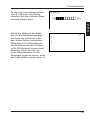
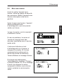
Measure what you see.
haze-gard dual
Manual
Betriebsanleitung
Mode de’emploi
A member of
Additives & Instruments
Français
Deutsch
Manual
Bedienungsanleitung
mode d‘emploi
English
haze-gard dual
Patent pending
Patent angemeldet
faire breveter
BYK-Gardner GmbH
Lausitzer Str. 8
D-82538 Geretsried
Germany
Tel.
0-800-gardner
(0-800-4273637)
+49-8171-3493-0
Fax
+49-8171-3493-140
www.byk.com/instruments
257 015 268 EDF 0809
BYK - Gardner USA
9104 Guilford Road
Columbia, MD 21046
USA
Phone 800-343-7721
301-483-6500
Fax
800-394-8215
301-483-6555
Français
Deutsch
English
English
This instruction manual is an important component of this equipment. It
contains essential information about
its installation, operation and use. If
you pass the device on to another
user, please ensure that the instruction manual is included. The manual
must be studied carefully before
working with the equipment. Please
contact your regional service office if
you have any questions or require
additional information about the
device.
The technology and fittings are
based on state-of-the art optic and
electronic technology. New developments and innovations are constantly being integrated into the equipment. Thus, the diagrams, dimensions, and technical data used in
this manual may have changed as a
result of the adaptation of the device
to new information and
improvements.
3
4
English
English
Contents
1
2
3
4
5
6
7
8
9
Safety Information .............................................................................. 8
System Description ............................................................................. 9
2.1 System Description .................................................................. 9
Startup .............................................................................................. 10
3.1 Important Notes ...................................................................... 10
3.2 Setting the Equipment Up ...................................................... 11
3.3 Power-up ................................................................................ 12
Features ........................................................................................... 15
4.1 Device .................................................................................... 15
4.2 Operation ................................................................................ 16
Selecting a Measurement Method .................................................... 17
5.1 Selecting a Measurement Method ......................................... 17
Calibration ........................................................................................ 19
6.1 Calibration .............................................................................. 19
6.2 How to Calibrate the Device .................................................. 19
6.3 Calibrating with other Standards ............................................ 20
6.4 Additional Standards for Monitoring Test Equipment ............. 22
6.5 Monitoring Test Equipment ..................................................... 22
6.6 Storing and Handling Standards ............................................ 22
6.7 Cleaning ................................................................................. 23
6.8 The Validity of Standard Values ............................................. 23
Measurement .................................................................................... 24
7.1 ISO Method ............................................................................ 24
7.2 ASTM Method ........................................................................ 25
7.3 Haze Measurement ................................................................ 25
Measurement Series with Statistics .................................................. 26
8.1 Measurement Series with Statistics ....................................... 26
8.2 Statistics with Continuous Mode ............................................ 27
8.3 Deleting One Measurement ................................................... 27
8.4 Deleting All Measurement ...................................................... 27
Continuous Mode ............................................................................. 28
9.1 Continuous Mode ISO Transmittance .................................... 28
Haze ....................................................................................... 29
Standby .................................................................................. 30
9.2 Continuous Mode ASTM Transmittance ................................ 31
Haze ....................................................................................... 31
9.3 Continuous Mode Statistics .................................................... 32
5
English
Contents
10
11
12
13
14
15
16
6
SET UP ............................................................................................. 33
10.1 General Information ............................................................... 33
10.2 Calibration .............................................................................. 34
10.3 Print Statistics ......................................................................... 34
10.4 Print Online ............................................................................. 34
10.5 Continuous Mode ................................................................... 35
10.6 Language ............................................................................... 35
10.7 Method ................................................................................... 35
10.8 Beeper .................................................................................... 36
10.9 Adjust Date ............................................................................. 36
10.10 Adjust Time ............................................................................. 37
10.11 Display Contrast ..................................................................... 37
10.12 Change Calibration Value ...................................................... 38
Temporary Storage ................................................................. 39
Continuous Storage ................................................................ 40
Parameters ....................................................................................... 41
11.1 Appearance of Transparent Materials .................................... 41
11.2 Criteria for the Evaluation of Transparency ........................... 41
11.3 The Measurement Principle ................................................... 42
11.4 Standards ............................................................................... 42
11.5 Notes ...................................................................................... 44
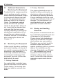
Care and Maintenance ..................................................................... 45
12.1 Changing the Lamp ................................................................ 45
12.2 Changing a Fuse .................................................................... 46
12.3 Maintenance ........................................................................... 47
Interface Description ........................................................................ 48
Technical Specifications ................................................................... 49
Delivery Information .......................................................................... 50
Error Messages ................................................................................ 51
7
English
English
1 Safety Infromation
No claims of product liability or
warrantee can be honored if the
device is not operated in accordance with the operating instructions or the instructions on
the instrument.
If you use the unit and accessories properly, there are no
hazards to fear – none of a
mechanical nature and none
caused by electrical shock.
The following paragraphs
contain information about the
safe use of the device.
Please use only accessories
that are available for the unit.
See „Delivery Notes“ and the
„Technical Data“ for further
information.
Avoid exposure to continuous
humidity and condensation (see
Technical Data). Avoid splashing with water, chemicals or
other liquids.
Do not perform any repairs on
the unit, neither mechanical nor
electrical. Please consult our
Technical Customer Service.
Only devices that meet the requirements for low – voltage
safety may be connected to the
RS 232 interface.
The power supply unit can be
disconnect from the power supply by disconnecting the power
connection line plug from the
8
socket. Make certain that the
power supply unit plug is easily
accessible. Use only the power
supply connection line included
with delivery.
Before placing the instrument into operation please check, if the
line voltage set on the power entry module corresponds to the
power supply system in your
facility.
Defects and extraordinary loads
If safe operation can no longer
be presumed, shut down the
device and secure it against
unintended operation.
The device must be presumed
unsafe to operate:
• if visible damage is evident
• if the instrument is no longer
working
• if it has been stored for long
periods under adverse conditions
• after harsh treatment during
shipping.
The instrument shall be connected only to power outlets with
faultless ground wire. If the connection to the ground wire is insufficient, the housing of the instrument may in cases of error
assume voltage potentials which
at contact represent a risk of
electric shock. In case of doubt
please have the proper construction of the ground wire inspected
by a specialist.
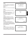
2.1
System Description
Please read the instruction
manual before placing the
instrument in service and
observe the safety
instructions.
The haze-gard dual is a stationary
instrument designed to measure the
appearance of glass and films,
packaging, and other parts made of
plastic and other transparent materials. The specimen surface is illuminated perpendicularly and the
transmitted light is measured photoelectronically using an integrating
sphere (0°/diffuse geometry). The
spectral sensitivity conforms to the
CIE standard spectral value under
standard lamp D65.
The two parameters:
• total transmittance
• haze
enable the full and objective characterization of visual appearance.
It is possible to switch between two
different international standardized
methods using this device:
• Compensated (ISO 13468 and
14782)
With the uncompensated method,
the surface reflection on the specimen is included in the measurement
result whereas with compensated
measurement, the value is independent of the specimen reflectance
properties (see Chapter 11, Parameters).
The haze-gard dual sets new standards in transparency measurement
instruments. Apart from its speed
and ease of operation, it also offers
the following features:
• High accuracy and reliability
thanks to reference-beam optics
• Long-term calibration and selfdiagnosis
• Open specimen area for the
measurement of small and large
products
• Automatic calibration and menudriven operation
• Closed optics and electronics
• Ready to operate; no lengthy
warm-up needed
• Foot switch
• Internal statistics functions
• Memory to store readings, PC
interface, printer outlet
• Uncompensated (ASTM D1003)
9
English
1 Safety Infromation
English
3 Startup
3.1
Important Notes!
Before operating the instrument for
the first time, please read the
instructions and note particularly the
safety information provided in
Chapter 1.1.
The device has no special
environmental requirements.
However, it is important to observe
the standard operating conditions
for electronic instruments. Please
avoid:
• excessive oscillations and
vibrations,
• extreme ambient temperatures or
rapid changes in temperature,
• relative humidity in excess of 85%
and splashing with water or other
liquids,
• contact with caustic and explosive
chemicals, vapors, and gases,
• extreme electromagnetic fields,
• intrusion of foreign objects or
extraneous matter through
measuring apertures.
10
The instrument chassis is resistant
to a number of solvents but cannot
be guaranteed to withstand contact
with all chemicals. Thus, use only a
small damp cloth for cleaning. A little
rubbing alcohol or mild detergent
may be used to remove stubborn
stains. Clean the front lens of the
clarity port with only a soft lint-free
cloth (preferably a damp optical
wipe).
Never clean the interior of the
detector sphere (haze-port)!
If the instrument malfunctions, do
not attempt to repair it yourself. Our
Customer Service will be glad to
provide you with rapid assistance.
3.2
English
3 Startup
Setting the Equipment Up
Always switch off the device
before plugging in or unplugging
the various connectors (foot
switch, printer cable, and power
cable)!
To ensure that the measurement
device is being used correctly
and safely, check that the voltage
setting is correct!
• Unpack the device and check for
possible damage sustained during
shipment (visual inspection).
• Before starting the device for the
first time, check that all
components have been delivered
(for a list of package contents, see
Chapter 15 Ordering Guide).
• Plug the enclosed power cord into
the device and into a grounded
power outlet.
• If applicable, plug the foot switch
and printer or PC connection into
the appropriate slots.
• Set the voltage selector on the
instrument and, if necessary,
change it to the correct setting as
follows: use an appropriate tool
(No. 2 screwdriver) to remove the
fuse insert below the power-cable
receptacle and plug the insert
back in so that the mark on the
power-switch coincides with the
required voltage range.
11
English
3 Startup
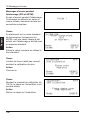
3.3
Power-Up
Before switching the device on,
remove the protective cover from
the haze ports. To switch on the
equipment, press the power switch
on the left side of the device.
The device will run a self-diagnostic
test after it is switched on, the
progress of which is indicated on
the display.
The first thing that appears on the
screen is the company logo along
with the software version number
and the copyright note. The version
number and year of copyright are
important for Customer Service if
you ever need to report a problem
with the device.
The device then carries out a selfdiagnostic test. The lamp, chopper,
and shutter are checked. If the
values for any of these components
are outside the tolerance range, an
error message is displayed.
If the lamp is faulty, the selfdiagnostic test is stopped. If this
happens, replace the lamp (see
Chapter 12). If an error is reported
for other components, please
contact our Customer Service.
12
When the self-diagnostic tests are
successfully completed, the stored
calibration values appear on the
display.
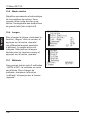
STATUS
The status display for the lamp and
sphere coating provides important
information about wear and tear on
the device. If the lamp status is
below 50%, it must be changed (see
Chapter 12). If the sphere coating
has dropped below 50%, we
recommend that you contact
Customer Service to arrange for
testing.
STATUS
The “Statistics Memory” status
display indicates the number of
readings stored in the device.
STATISTIC-MEMORY
English
3 Startup
Transmission Std.
100.0%
Lamp Status
100%
Sphere Coating
100%
7.54 am
Time:
28.05.1999
Date:
T:
H:
T&H:
n=
n=
n=
4
5
7
13
English
3 Startup
A short warm-up of only two minutes
follows. The status of the warm-up
process is indicated on the display.
As soon as the instrument has
completed the self-diagnosis and
status displays, it returns to the
mode which was active at the last
shutdown. It is now ready for operation. The ISO method (compensated
measurement) is active when the
device is delivered. The device must
be calibrated before measurements
can be taken after it is started for
the first time (Chapter 6).
14
WARM-UP
0%
T
H
100%
ISO
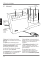
4.1
English
4 Features
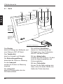
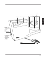
Device
The display is used to output
measurement values and display
messages from the SET-UP dialog.
The button field is used for
selecting and inputting functions.
The haze port illuminates the
specimen to be measured.
The specimens to be measured are
placed at the haze port.
The comp port is used for compensation measurement for the ISO
method.
The side connections are used to
connect the device to the mains
electricity supply, foot switch, PC,
and printer.
The power switch is used to switch
on the device. It also functions as a
voltage selector and fuse switch.
If you need both hands to hold the
specimen, it is possible to start
measurement by pressing the foot
switch.
15
English
4 Features
4.2
Operation
Measurement and
Selection key
Cursor Keys
Reference measurement
(Continuous Mode)
delete last
statistic
result
on/off
on/off
operate
set up
reference
transmittance
haze
transm.
+ haze
delete all
SET-UP Menu
Measurement selection
The operate and selection buttons
are pressed to start the measurement and to select the measurement method.
transm.+ haze selects both
methods simultaneously.
operate starts a measurement.
set up button
reference starts a reference measurement in continuous measurement mode.
The cursor buttons are used to
move the index
mark along the
menu for the selection of menu
items.
transmittance selects the transmission measurement method.
haze selects the haze measurement
method.
To display the SET-UP Menu
press the
operate confirms the selection
made.
set up cancels a process.
16
5.1
English
5 Selecting the Measurement Method
Selecting the Measurement
Method
Two standardized measurement
methods are available using this
device.
T
• Compensated (ISO 13468 and
14782)
H
ASTM
• Uncompensated (ASTM D1003)
The active measurement method is
displayed on the top right.
The measurement method can be
changed from the SET-UP Menu.
delete last
This menu is accessed using the
buttons shown here:
The menu is opened by pressing
the “set up” button.
statistic
result
on/off
on/off
operate
set up
delete all
To select options within the SET-UP
Menu, use the cursor buttons and
the “operate” and “set up” buttons.
The other labels on the cursor
buttons are irrelevant here.
17
English
5 Selecting the Measurement Method
Open the SET-UP Menu using the
cursor buttons.
The first part of the SET-UP Menu is
shown on the display.
To select the measurement method,
scroll down to the item “Method“
using the cursor buttons and press
the “operate” button.
The displayed method will change
and a message will appear
concerning the “comp-port”:
SET UP MENU
Calibrate
Print Statistic
Print Online:
Cont. Mode:
Language:
Method:
Escape:
SET
on
off
USA
ISO
UP
• Changing to ASTM:
cover the comp-port.
• Changing to ISO:
uncover from the comp-port.
Once a measurement mode has
been selected, the corresponding
calibration routine is started
immediately.
18
Attention!
Keep
comp-port
open
Continue:
ISO
OPERATE
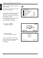
6.1
English
6 Calibration
Calibration
Thanks to the use of state-of-the-art
technology and the reference beam
principle, calibration does not have
to be carried out very often. We
recommend a calibration interval of
two months. Calibration is also
necessary:
• at the initial startup,
• in the event of a drastic change in
ambient temperature (for
example, if the device has been
moved to a new location),
• if a message appears on the
display requesting calibration (e.g.
following the modification of
stored calibration values),
• if the measurement method has
been changed.
6.2
How to Calibrate the Device
Calibration is carried out in the SETUP Menu. This menu is opened by
pressing the “set up” button. Using
the cursor buttons, select the menu
item “Calibration” and then press
the “operate” button. The dark
measurement is carried out. Cover
the “haze-port” with the dark
standard and press the “operate”
button again.
CALIBRATION
Zero Calibration
ASTM
Please cover
haze-port
Ready:
Escape:
OPERATE
SET UP
To interrupt the calibration procedure at any time, press the “set up”
button.
19
English
6 Calibration
A message is shown on the display
while the measurement is being
carried out.
Measurement
active
The bright measurement follows the
dark measurement. For this, remove
the dark standard from the hazeport and press the “operate“ button.
Please remove cover
from haze-port
Ready:
The device completes the bright
measurement and then returns to
standby mode. Calibration is now
complete and the device is ready to
carry out measurements.
6.3
Calibrating with other
Standards
The device can also be calibrated
and tested with a reference standard in the ASTM measurement
method (see Accessories/Delivery
Package). To enable this, the
calibration data for this standard
must be already entered in the SETUP menu (Chapter 10.12). In this
case, the relevant standard must be
placed at the haze-port for
calibration.
20
ISO
CALIBRATION
100% Calibration
T
H
OPERATE
ISO
English
6 Calibration
For dark measurement, cover the
haze-port with the dark standard
and press the “operate” button.
The dark measurement is followed
by bright measurement. For this,
remove the dark standard from the
haze-port and press the “operate”
button again.
You will then be asked to place the
standard that was entered in the
SET-UP Menu. Calibration is
complete when you press the
“operate” button and the device is
ready for measurement.
CALIBRATION
Place Transm.stand.
90.0
at haze-port
Ready:
Escape:
OPERATE
SET UP
To avoid confusion, please ensure
that the value shown during
calibration coincides with the data
for the standard used.
The manufacturer’s original
standards must be used to
guarantee accurate calibration.
21
English
6 Calibration
6.4
Additional Standards for
Monitoring Test Equipment
To check that the measurement device is working correctly, measurements should be performed at regular intervals with special test standards. The appropriate test standards are listed in the Ordering
Guide. The displayed readings
should fall within the specified
values for the standard. If they do
not, check that the standard was
clean and that the device was
correctly calibrated. If cleaning the
standard and recalibration do not
correct the error, please contact
Customer Service. For information
about cleaning the device, see
Chapter 6.7.
6.5
Monitoring Test Equipment
Under normal laboratory conditions
and careful handling, an interval of
one month is recommended for the
monitoring of test equipment. If
measuring conditions necessitate
more frequent monitoring of the
equipment, two sets of haze standards should be used:
1. Working Standards
Any material that is suitably homogenous and stable can be used for
routine testing. The working standards are based on primary standards.
22
2. Primary Standards
The primary standards are not intended for daily monitoring but exclusively as reference material for
the checking of working standards.
Primary standards should be used
as little as possible due to the risk of
damage. The manufacturer’s original standards must be used to
guarantee accurate calibration.
6.6
Storing and Handling
Standards
6.6 Storing and Handling
The precision
of measurements can
Standards
be considerably impaired by the use
The precision of measurements can
of damaged or dirty standards.
be considerably impaired by the use
Please ensure that standards are
of damaged or dirty standards.
clean and unscratched. The stanPlease ensure that standards are
dard surfaces are very sensitive.
clean and unscratched. The stanTherefore, you must not touch the
dard surfaces are very sensitive.
standard surface and protect it
Therefore, you must not touch the
against scratching (store in a secure
standard surface and protect it
iplace). For instructions on the
against scratching (store in a secure
cleaning of standards, see Chapter
iplace). For instructions on the
6.7. The standards must not be
cleaning of standards, see Chapter
exposed to direct sunlight or be
6.7. The standards must not be
stored in a dirty or dusty environexposed to direct sunlight or be
ment. Contact with chemicals and
stored in a dirty or dusty environaggressive vapors must also be
ment. Contact with chemicals and
avoided.
aggressive vapors must also be
avoided.
6.7
Cleaning
The standard surfaces are very
sensitive. Hence, standards should
be cleaned as seldom as possible.
Dust and lint can cause incorrect
measurements. Thus, standards
must be cleaned with oil-free compressed air before use.
Never rub the standard dry!
The rubbing action may cause
scratches from surface dust.
6.8
The Validity of Standard
Values
Even if handled carefully, the measurement values of the standards
can change due to environmental
factors. Thus, primary standards
should be measured regularly by
the Byk-Gardner Service.
A monitoring interval of one year is
recommended in this case.
Extreme care must be taken when
cleaning standards. Use a fresh soft
cloth and wash the standards in distilled water. Do not apply pressure
or rubbing action. Ensure that there
are no particles adhering to the
cloth that might damage the standard surface.
Do not use aggressive cleaners
such as solvents, rubbing alcohol,
trichloroethylene, benzene, strong
alcohols, acids or lyes. Chemical
cleaners and polishes are equally
damaging.
To remove stubborn dirt, add a little
household dish detergent (acid-free)
to the water. Rinse in distilled water.
Dry with oil-free compressed air and
blow off any remaining dust or lint.
Do not rub the standard dry! The
rubbing action may cause scratches
from surface dust.
23
English
6 Calibration
English
7 Measurement
7.1
ISO Method
If the “transm. + haze” parameter is
selected, the device is ready to
carry out measurements in accordance with the ISO method. The
comp-port is open. Press the “operate” button. You will then be requested to place the specimen at
the comp-port.
Place
sample at
comp-port
Ready:
OPERATE
The specimen must be held level
with the port during measurement.
Press the “operate” button. The
device will start measuring. The
following message appears during
measurement:
“Measurement active”.
You will then be requested to place
the specimen at the haze port.
Place the specimen at the haze port
and press the “operate” button.
Please place
sample at
haze-port
Ready:
OPERATE
The following message is displayed
again:
“Measurement active”.
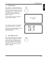
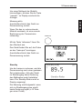
The result is displayed and the
measurement process is complete.
Transmission measurement is identical to the measurement procedure
described above.
24
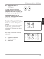
T
H
91.8
18.3
ISO
7.2
ASTM Method
The “transm. + haze” parameter is
selected, the comp port is covered,
and the device is ready to carry out
measurements in accordance with
the ASTM method. Place your
specimen at the haze port and
press “operate”.
transm.
+ haze
The following message appears:
“Measurement active”.
Measurement
active
The result is shown on the display
and measurement is complete.
T
Transmission measurement follows
the same procedure as that
described above.
H
7.3
English
7 Measurement
91.8
18.3
ASTM
Haze Measurement
If the Haze parameter is selected,
the procedure is identical to those
for the ISO and ASTM methods.
Place the probe on the haze port
and press “operate”. The result is
appears after the “Measurement
active” message.
25
English
8 Measurement Series with Statistics
8.1
Measurement Series with
Statistics
The statistics function can be selected alone or for any combination of
parameters. They are activated
using the “left/right” cursor buttons.
In this case, the indication above
and below the buttons is valid.
statistic
result
on/off
on/off
Statistics can only be recorded for
one parameter in Continuous Mode.
The “statistic on/off” button is used
to switch the statistics function on or
off for the existing representation of
measurement values.
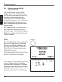
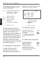
T
H
91.8
18.3
ASTM
The following data is also shown on
the display:
n = Number of measurements
m = Mean
s = Standard deviation
26
STATISTIC
T
H
90.8
18.3
ASTM
n= 14
m= 91.6
s= 1.2
m= 17.0
s= 1.8
English
8 Measurement Series with Statistics
All statistics data can be switched
on by pressing the “result on/off”
button.
act
= Last measured value; in
Continuous Mode, this is the value
for the inserted specimen
m
= Mean value
min
= Minimum value
max = Maximum value
s
= Standard deviation
v
= Variance coefficient
When the statistics function is
active, the measured values are
saved and retained when you switch
to a different parameter or switch off
the instrument. The saved values
can be transmitted to a printer or PC
via the serial interface. A previously
saved measurement series can be
called up again and continued if it
has not been deleted. It is not
possible to change calibration
values while a series is running, as
this would falsify the statistical
results.
8.2
Statistics with Continuous
Mode
In Continuous Mode, measurements
are displayed continuously but they
are not saved automatically. To add
a measurement to the measurement
series, it is necessary to press the
“operate” button.
RESULT
act=
m=
min=
max=
s=
v=
S=
T
90.8
90.6
87.2
91.3
1.02
1.12
H
8.79
8.14
6.93
9.79
0.71
8.77
ASTM
n= 14
n
2
1
(x -x)
n-1 i=1 i
V = 100 x s / m %
8.3
Deleting One Measurement
The “delete last” button
deletes the last saved
measurement.
delete last
The counter variable “n” is
decreased by 1.
8.4
Deleting All Measurements
The “delete last” button
deletes all measurement
in this series.
The deletion function only
relates to the parameters
currently set in the memory
area.
delete all
27
English
9 Continuous Mode
In the normal measuring mode,
individual measurements are started
by pressing the “operate” button or
the foot switch. In Continuous
Mode, the specimen is measured
repeatedly and the result on the
display updated accordingly. This
allows you to run a large specimen
through the device to establish
whether its quality is homogenous.
The Continuous Mode function can
only be implemented for a single
parameter. If you try to switch to
Continuous Mode for the “transm. +
Haze” parameters, the following
warning appears on the display:
Continuous reading
only in
single mode
Select one parameter and select
Continuous Mode in the SETUP
menu by pressing the “operate”
button.
9.1
Continuous Mode ISO
Transmittance
Transmittance measurement requires a compensation measurement as a reference. A message on
the display will ask for the definition
of the compensation.
Compensation
Measurement
Place
Sample at
comp-port
Place your specimen at the compport and press the “operate” button.
Ready:
The “Measurement active” message
will appear on the display and the
device will then start the continuous
measurement. Then place the
specimen at the haze-port. The
values are displayed continuously.
CONT. MODE
28
T
90.8
OPERATE
ISO
English
9 Continuous Mode
To add a value to the statistics,
press the “operate” button. The
following message appears on the
display:
Measurement active.
The device will return to continuous
mode. If the statistic function is activated (Chapter 8.3), the counter will
increase by one after measurement.
If you change the material to be
measured, a new compensation
measurement is required. Indicate
the change by pressing the “reference” button.
You will be asked to place the specimen in the comp-port. The compensation measurement is triggered
by pressing the “operate” button.
The device will then return to continuous mode.
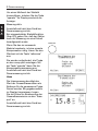
Haze
The haze measurement requires the
value of the total transmittance as a
reference for the measured specimen. This is indicated in a message
on the display. Place the specimen
whose total transmittance is to be
defined at the haze-port.
The device will return to Continuous
Mode on completion.
reference
Compensation
Measurement
Place
Sample at
comp-port
Ready:
OPERATE
Transmittance
Measurement
Please place
Sample at
haze-port
OPERATE
Ready:
ISO
CONT. MODE
H
15.8
n=
m=
s=
11
14.6
1.16
29
English
9 Continuous Mode
To add a value to the statistics,
press the “operate” button. The
following message appears on the
display:
Measurement active.
The device will then return to
Continuous Mode on completion.
If you change the material to be
tested, the transmission must be
redefined.
Indicate the change by pressing the
“reference” button.
reference
A message on the display will
request you to place the specimen
in the haze port.
Transmittance
Measurement
The device will then return to
Continuous Mode.
Please place
Sample at
haze-port
Ready:
OPERATE
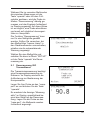
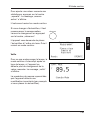
Standby
To protect the lamp, Continuous
Mode is interrupted after a certain
period if the device fails to establish
any change in the measurement
value at the beam aperture.
Measurement is continued if a
significant change is detected at the
beam inlet (e.g. placing of a
specimen).
30
CONT. MODE
T
89.5
Standby-Mode
ISO
9.2
English
9 Continuous Mode
Continuous Mode ASTM
Transmittance
Conversion to Continuous Mode in
the ASTM measurement method is
the same as that for ISO, the only
difference being that the comp port
must be covered. A message is
displayed indicating this. There is no
definition of compensation with this
method. Neither are precautionary
measures are required if the material being tested is changed. The
measurement values are saved by
pressing the “operate” button.
Haze
The transmission must be measured with the Haze parameter. This
is also indicated on the display. The
redefinition of the transmission is
triggered by pressing the “reference”
button.
reference
!"##
"$!#
You will be requested to place the
specimen at the haze-port.
The device will carry out the measurement with the new reference. The
haze value is then shown on the
display. The corresponding transmission value is indicated in the top
right corner of the display.
" #
& !#
%
31
English
9 Continuous Mode
To save a measurement value and
return to standby mode, proceed as
described above under ISO
Continuous Mode.
9.3
Continuous Mode Statistics
It is also possible to carry out a
statistical evaluation of the measurement values in Continuous Mode.
The measured values are written to
the same memory as in normal
operation.
Select the desired function by
pressing the
statistic
“statistic” :
on/off
or
result
“result” button.
on/off
The selected function is indicated
on the display.
You can now run the desired area of
your specimen through the device
and observe the measurement
values on the display. If you wish to
save a value, press the “operate”
button or foot switch.
32
CONT. MODE
H
12.7
T:
n=
m=
s=
ASTM
89.4
11
10.6
1.16
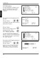
10.1 General Information
The SET-UP menu allows you to set
the various device parameters,
select a language, and carry out
calibration. The SET-UP menu and
settings within the menu are
executed using these buttons:
To call up the SET-UP menu, press
the “set up” button.
delete last
statistic
result
on/off
on/off
operate
set up
delete all
An operator instruction message
appears. To select the individual
menu items or pages, press the
“up”/“down” cursor buttons.
Press the button:
The first menu page appears with
the following selection items.
If you move down the menu
with the button: the second
page of the SET-UP menu
appears. Select the menu item you
would like to change by marking the
item in question. Press the “operate”
button to implement the change or
press “set up” to cancel. The diagram shows the menu in ASTM
mode. Select the menu item you
would like to change by marking the
item. Press the “operate” button to
change or press “set up” button to
cancel. The diagram shows the
menu in the ASTM setting. The item
Change Cal. Value does not feature
in the ISO mode.
SET UP MENU
Calibrate
Print Statistic
Print Online:
Cont. Mode:
Language:
Method:
Escape:
SET
on
off
USA
ASTM
UP
33
English
10 SET-UP
English
10 SET-UP
10.2 Calibration
Calibration is described in Chapter 6
from page 19.
10.3 Print Statistics
Select the “Print Statistics” menu
item and press the “operate” button.
The data in the selected statistics
memory is output on the connected
printer.
SET UP MENU
Calibrate
Print Statistic
Print Online:
Cont. Mode:
Language:
Method:
Escape:
SET
on
off
USA
ASTM
UP
Print Statistic
T :
n=
8
28.05.1999
Date:
Time:
9:55 am
10.4 Print Online
Select the “Print Statistics” menu
item and press the “operate” button
to change the setting.
If the “Print Online” function is
activated, the measurement data is
output directly to the connected
printer after each measurement.
34
No.:
Escape:
SET UP
English
10 SET-UP
10.5 Continuous Mode
If the Continuous Mode function is
selected, the device constantly
repeats the measurement procedure. This function can be used to
check larger specimens for
homogeneity (see Chapter 9).
10.6 Language
To change the language, select the
menu item “Language” and press
the “operate” button.
The selection menu for the available languages is displayed. The
currently selected language is
marked. Select the desired
language using the cursor buttons
and press the “operate” button to
confirm your selection.
SET UP MENU
Calibrate
Print Statistic
Print Online:
Cont. Mode:
Language:
Method:
Escape:
SET
German
English
French
Italian
Spanish
Japanese
Confirm:
Escape:
on
off
USA
ASTM
UP
OPERATE
SET UP
10.7 Method
It is possible to select between the
ASTM and ISO measurement
methods. The currently active
measurement method is indicated
under the “Method” menu item. To
change the measurement method,
select “Method” and press the
“operate” button. The displayed
measurement method is changed
and the device immediately
switches to the calibration function
for the selected measurement
method. You must now carry out the
calibration. (Chapter 6, p 19).
35
English
10 SET-UP
10.8 Beeper
The device emits a beep signal on
completion of a measurement. The
beep signal can be switched on or
off from the “Beeper” menu item.
10.9 Adjust Date
To change the date, select “Adjust
Date” and press the “operate”
button.
SET UP MENU
Beeper:
Adjust Date
Adjust Time
Display Contrast
Change Cal Value
Escape:
The date input menu is displayed.
Use the:
buttons, to move the arrow to the
item to be changed.
Use the:
buttons to change the value in
the corresponding place.
Years prior to 1980 are not
accepted.
36
on
SET UP
10.10 Adjust Time
To change the device time, select
the item “Adjust Time” and press the
“operate” button.
SET UP MENU
Beeper:
Adjust Date
Adjust Time
Display Contrast
Change Cal Value
Escape:
The time input menu is displayed.
Using the :
buttons, move the arrow to the item
to be changed.
Using the:
English
10 SET-UP
on
SET UP
Time:
15:40
New Time:
hh:mm
15:45
Confirm:
Escape:
OPERATE
SET UP
buttons, change the value in
the relevant place.
10.11 Display Contrast
To change the display contrast,
select the item “Display Contrast”
and press the “operate” button.
The input mask for changing the
contrast is displayed.
Using the :
SET UP MENU
Beeper:
Adjust Date
Adjust Time
Display Contrast
Change Cal Value
Escape:
SET UP
Contrast:
1
buttons, set the contrast on a scale
of 1-10. The higher the value, the
higher the contrast.
on
Confirm:
Escape:
10
OPERATE
SET UP
37
English
10 SET-UP
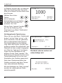
10.12 Change Calibration Value
This menu item is only available
under the ASTM measurement
method.
The value for the calibration standard is stored in the measurement
device. During calibration this data
is assigned to the relevant standard. Transmission is 100% with free
optical path. In individual cases, it
may be necessary to adjust the
stored data to a new standard, e.g.,
if you are using internal house
standards whose transmission is
known to you. You can also
calibrate and check the device with
the transmission standard set which
is available as an accessory (See
Chapter 6.2 Calibrating with Other
Standards).
Select the menu item Change
Cal. Values Press the “operate” button.
SET UP MENU
Beeper:
Adjust Date
Adjust Time
Display Contrast
Change Cal Value
Escape:
Select “Transmission Std.” and
press the “operate” button.
on
SET UP
Change Cal. Values
Input Trans Std.
Save Std Values
Escape:
38
SET UP
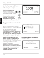
The value to be changed is shown
as a four-digit figure on the display.
The last digit here is the digit after
the decimal point.
Select the decimal
point to be changed
using the buttons:
T.Std. =
100
Confirm:
Escape:
OPERATE
SET UP
1000
English
10 SET-UP
and change the value using
the “up/down” cursor buttons.
Confirm the change by pressing the “operate” button. The
device will return to the Change Cal
Values menu.
Temporary Storage
If you leave the Change Cal Values
by pressing the “set-up” button (i.e.
cancel), the altered value is adopted temporarily. The device starts
calibrating. After the dark and light
measurement, you will be requested
to place the standard with the value
just entered at the haze port. Insert
the standard and press the
“operate” button. The calibration is
finished and the new transmission
value is now saved until the device
is switched off.
When the device is switched on
again, the following message
appears beside the company logo.
Change Cal. Values
Input Trans Std.
Save Std Values
Escape:
SET UP
Standards must be clean and
undamaged!
Adjusting
Calibration Values
Calibration data is being updated.
Continue:
OPERATE
39
English
10 SET-UP
Continuous Storage
To permanently store the altered
value of a calibration standard in the
device, go to the Change Cal.
Values. menu and select the
option “Save Std Values”
using the cursor buttons and
then press the “operate”
button.
The “Save Std Values” display
appears.
The old and new value are
presented here.
To confirm the new value, press the
“operate” button.
The device starts calibrating. After
the dark and light measurement,
you will be requested to place the
standard with the value just entered
at the haze port. Insert the standard
and press the “operate” button. The
calibration is finished and the new
transmission value is now
permanently stored.
40
Change Cal. Values
Input Trans Std.
Save Std Values
Escape:
SET UP
Initialize Instr.
Old
100
Save Data:
Escape:
New
90
OPERATE
SET UP
Standards must be clean and
undamaged!
11.1 Appearance of Transparent
Materials
11.2 Criteria for the Evaluation
of Transparency
When a transparent specimen is
illuminated by focused light, a
number of effects may result,
depending on the nature of the
material:
The appearance of a transparent
product is a function of gloss, color,
and transparency. The key parameters with respect to transparency
are total transmittance and haze.
• Homogenous material with a
smooth surface
The total transmittance is the ratio of
the total transmitted light to incident
light. It is reduced by reflectance
and absorbance.
Some of the light will be reflected
from the border surfaces and some
will pass through the specimen unaltered. The specimen will appear
glossy and crystal clear.
The intensity of the transmitted light
will be diminished by the inherent
absobance of the materials, dyes, or
pigments.
According to ASTM 1003, haze is
the percentage of light that deviates
from the incident beam by more
than 2.5° on average.
• Haze
Diffuse scattering will decrease the
imaging quality of an object. Particles or irregularities in the material
may act as “scatterers”. The light in
these areas is diffused uniformly in
all directions and the light intensity
per angle is small. This reduces
contrast and results in a milky or
cloudy appearance. This effect is
called haze.
41
English
11 Parameters
English
11 Parameters
Light trap
Illumination
Specimen
comp-port
11.3 The Measurement Principle
11.4 Standards
A beam strikes the specimen and
then enters an integrating sphere.
The light, which is uniformly distributed by the matte white coating on
the sphere wall is measured by a
detector. The total transmittance is
measured with the sphere outlet
closed and haze is measured with
the outlet open.
ASTM D 1003:
In the measurement method based
on ISO 13468 and ISO 14782, the
sphere effectiveness is taken into
account in the measurement.
ISO 13468
Standard Test Method for Haze and
Luminous Transmittance of Transparent Plastics.
ASTM D 1044:
Standard Test Method for Resistance of Transparent Plastics to
Surface Abrasion.
Plastics - Determination of the total
luminous transmittance of transparent materials.
ISO 14782
Plastics - Determination of haze for
transparent materials.
42
Calibration
English
11 Parameters
Measurement
Specimen
No compensation: different sphere efficiency
ASTM D 1003
Measurement conditions during calibration and actual measurement are
different. While part of the light that enters through the outlet escapes
calibration, during measurement the outlet with the specimen is closed.
Thus, the light in the sphere is increased by the proportion which is reflected
on the specimen.
Calibration
Measurement
Specimen
With compensation: same sphere efficiency
ISO 13468
Measurement conditions during calibration and actual measurement are the
same. The specimen is placed at the compensation outlet during calibration
and during measurement it is placed at the measurement outlet. This means
that the sphere efficacy is completely dependent on the reflectance
properties of the specimen. The difference between the two measurement
methods can be up to 2% for clear glossy specimens.
43
English
11 Parameters
11.5 Notes
• For values of less than 10 %, the
measurement range is automatically converted to a display with
two decimal places.
• During measurement, the mean
is taken across the illuminated
surface of the specimen. As it
cannot be assumed that the
optical properties are the same for
the entire surface of the specimen, we recommend taking
readings at several points on the
specimen and calculating a mean
value.
• There is little sense in taking
readings from dirty, scratched,
or otherwise damaged specimen
areas, unless you wish to obtain
the measurements as an indication of the extent of the damage,
e.g. measuring abrasion resistance (Taber Abraser).
• Specimen surfaces must be as
plane-parallel as possible; a
wedge shape will deflect light.
• When taking comparative measurements, note the specimen thickness, since absorbance and
scattering increase in direct proportion to thickness.
44
• Differences in reflection characteristics may affect transparency
measurements. If specimens are
glossy on one side and dull on the
other, the same surface should
always be directed toward the
sphere aperture.
• Optical quality cuvettes with
plane-parallel walls and an edge
length of at least 50 mm can be
used to take readings on liquids
(Chapter 15).
• In practice, it may be important to
know whether scattering is caused
by internal scatterers or surface
structure. In these cases, surface
scattering can be eliminated by
immersing the specimen during
the readings in a liquid with the
same refractive index as the
specimen. Only bulk scattering
will then come into play.
English
12 Care and Maintenance
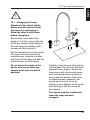
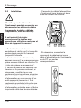
12.1 Changing the Lamp
Attention! First switch off the
device and disconnect it from
the mains by unplugging it.
Allow the lamp to cool down
before changing it.
Remove the cover above the
display. To do this, remove the top
of the two screws. Press lightly on
the side facing the display until it
moves and then remove it.
2.
1.
3.
Pull the lead plug out of the socket.
The lamp unit is secured with a
knurled screw. Unscrew the latter
and then pull the lamp unit with the
knurled screw out of the base.
Do not touch the inside of the
device and do not allow any
objects to fall into the device
aperture!
Carefully insert the new lamp device
into the base. Do not touch the lamp
glass with your fingers. Secure the
lamp device with the knurled screw
and connect the lead plug with the
base inside the device. Check that
no objects remain trapped in the
device and close the cover by
pushing it from behind into the guide
and securing it with the screw on
the chassis.
The device must be recalibrated
when the lamp has been
changed.
45
English
12 Care and Maintenance
12.2 Changing a Fuse
Caution: First switch off the device and disconnect it from the
mains electricity supply by unplugging it.
Caution: For continued protection against risk of fire replace
only with same type and rating of
fuse.
Pull the fuse holder from the mains
plug socket (left side of device)
using a suitable tool (No. 2 screw
driver). Replace the defective fuse
with a new one. Use only the recommended fuse type (Technical
Specifications, Chapter 14). Replace the fuse device so that the arrow
beside the voltage used points to
the mark on the device case.
Only use the specified fuse type.
Never resort to short circuiting!
The marking on the voltage used
must coincide with the marking
on the device chassis.
46
English
12 Care and Maintenance
12.3 Maintenance
Attention! First switch off the
device and disconnect it from
the mains electricity supply by
unplugging it.
The device chassis is resistant to a
number of solvents but cannot be
guaranteed to withstand all chemicals. Use only a soft damp cloth for
cleaning. A little rubbing alcohol or
mild detergent may be used to
remove stubborn dirt Clean the front
lens of the clarity port only with a
soft lint-free cloth.
Never clean the interior of the
detector sphere (haze-port)!
If the instrument malfunctions, do
not attempt to repair it yourself. Our
Customer Service will be glad to
provide you with rapid assistance.
47
English
13 Interface Description
The device is equipped with a serial
interface ( RS-232 ) which can be
used to control the device, for further processing of measurement
data on PC, or the output of data on
a corresponding printer. The device
has a 9-pole SUB-D socket for data
transmission with the following pin
arrangement:
Measurement device
PC
3 TxD
3 RxD
2 RxD
2 TxD
7 RTS
5 CTS
8 CTS
4 RTS
5 GND
7 GND
1
6
9
5
The serial asynchronous transmission is defined in the measurement
device and is implemented on the
basis of the following specifications:
9600 baud, 8 data bits, no parity,
1 stopbit.
48
Measurement
geometry:
Sample Port:
Measurement
Area:
0°/diffuse
21.0 mm
(0.85 in.)
16.5 mm
(0.65 in.)
Color sensitivity:
In spectral adaptation to CIE
luminosity function y under
standard illuminant D65
Connections:
RS-232:
Foot switch:
Voltage:
Power
consumption:
Fuse:
Measurement range:
Transmission:
0–100%
Haze:
0–100%
Display
resolution:
0.01 in area
from 0.00 to 9.99
0.1 in the range
from 10.0 to 99.9
Repeatability:
± 0,1 units*
Reproducibility:
± 0,4 units*
Measurement
time:
1–6 seconds
(depending
on mode)
Statistics
memory:
English
14 Technical Specifications
9-pole Sub-D
15-pole Sub-D
230V/50 Hz,
115V/60 Hz
max. 200 VA
Slow blow
1.0A;250V
(230 V)
Slow blow
1.6A;250V
(115 V)
Operating
temperature:
Storage
temperature:
+ 10°C to + 40°C
(+ 50 to 104°F)
0°C to +50°C
(+ 32 to 122°F)
Dimensions:
39 x 67 x 24 cm
(15 x 26 x 10 in.)
Weight:
18 kg (40 lbs)
3 x 999 values
battery buffered
lithium cell 3V
(CR 2450N FH)
Interface :
Serial RS-232
with dialog
capacity
*standard deviation
Technical Data Subject to Alteration
49
English
15 Delivery Information
Delivery package
haze-gard dual
basic version
Comprising:
s -EASUREMENTDEVICE
s )NTERFACECABLE
for connection to
PC or printer
s 3OFTWAREEASYLINK
s &OOTSWITCH
s #OVER
s $ARKSTANDARD
s SHEETHOLDERS
(6 cm and 12 cm)
s -AINSCABLE
Order No.
Delivery package
s 3ERIALPORTABLE
40 character
printer 230 V
s 3ERIALPORTABLE
40 character
!4
printer 115 V
s (OLDERFOR4ABER
Abraser (resistance
!4
measurement)
s ,AMP
s
s#UVETTEHOLDER
AT-4727
Order No.
!4
!4
!4
!4
#UVETTESMMEDGELENGTH
s 0ATHLENGTHMM
!4
s 0ATHLENGTHMM
!4
s 0ATHLENGTHMM
!4
s 0ATHLENGTHMM
!4
Accessories
Haze Test Standards:
s (AZEAPPROX
s (AZEAPPROX
s (AZEAPPROX
s (AZEAPPROX
s (AZEAPPROX
s 3ETOFUNITS
!4
!4
!4
!4
!4
!4
Transmission standards:
s 4RANSMAPPROX
s 4RANSMAPPROX
s 4RANSMAPPROX
s 4RANSMAPPROX
s 3ETOFFOUR
!4
!4
!4
!4 General terms and conditions apply
!4 for warranty
50
English
16 Error Messages
Cause
The current statistics memory in the
measurement device does not
contain any data.
No statistic
values stored
Cause
The connected printer is not responding. This error only occurs
when statistics data is being printed. The printer is not polled
during online mode.
Printer
not ready
Escape:
SET UP
Remedy
• Check that the printer cable is
correctly connected!
• Is the printer switched on?
• Is there paper in the printer?
• Is the printer expecting a
postscript file?
Cause
Invalid date
A date earlier than 1980 was input
during SET-UP.
Remedy
The date input was ignored and the
old date retained. Enter the correct
date.
51
English
16 Error Messages
Cause
The “reference” button was pressed
although the device is not in
Continuous Mode.
Ref. Measurement
only in
Continuous-Mode
Remedy
None, this is merely provided for
information purposes.
Cause
The current statistics memory is full.
Memory
full
Remedy
Delete the last value or entire
memory by pressing the “delete
last” or “delete all” button.
Cause
The RAM and EEPROM contain
different calibration data as these
were not saved following the changing of calibration values.
Adjusting
Calibration Values
Remedy
The calibration data are automatically transmitted from the
EEPROM to the RAM and thus the
calibration values updated again.
Continue:
OPERATE
Cause
The measurement device is in
online mode and is hence controlled
from the PC- Only the “operate” and
referencee buttons and the “foot
switch” are released.
52
Online Mode
Keyboard inactive
English
16 Error Messages
Error messages during
calibration (ISO and ASTM):
If errors occur during calibration, the
device evaluates the measurement
process as an error and requests
the following corrections, depending
on the procedure involved:
"#
Cause
During calibration to a different
transmission standard (ASTM only),
the value was incorrectly entered or
an attempt was made to calibrate
using the incorrect standard.
Remedy
#(%)$)*%
*!-'&(*
,
)'
Enter the correct value or use the
correct standard.
Cause
The haze-port was not covered
during dark measurement.
Remedy
Cover the haze-port.
#"(*"&% (&#"(*"&%
#)&+(
-'&(*
,
)'
Cause
The cover or specimen were not
removed for light measurement
Remedy
Remove cover or specimen.
#"(*"&% #"(*"&%
#)($&+&+(
(&$!-'&(*
,
53
54
English
Deutsch
Diese Betriebsanleitung ist Bestandteil des Gerätes. Sie enthält wichtige Hinweise zur Aufstellung,
Inbetriebnahme und Handhabung.
Achten Sie bei der Weitergabe des
Gerätes darauf, dass die Betriebsanleitung dem Gerät beigefügt ist.
Sie ist vor Beginn der Arbeit aufmerksam zu lesen. Sollten Sie
zusätzliche Fragen haben oder
Informationen wünschen, wenden
Sie sich bitte an Ihre regionale
Servicestelle.
Technik und Ausstattung entsprechen dem neuesten Stand optischer
und elektronischer Technik. Weiterentwicklungen und Verbesserungen
werden laufend berücksichtigt; daher können sich Abbildungen, Maße
oder technische Daten, die in dieser
Betriebsanleitung verwendet wurden, in der Zwischenzeit durch Anpassung an neue Erkenntnisse und
Verbesserungen verändert haben.
3
55
56
Deutsch
1
2
3
4
5
6
7
8
9
Sicherheitshinweise ............................................................................ 60
1.
Sicherheitshinweise ................................................................. 60
Systembeschreibung ........................................................................ 62
2.1
Systembeschreibung.............................................................. 62
Inbetriebnahme................................................................................. 63
3.1
Wichtige Hinweise vor der Inbetriebnahme ........................... 63
3.2
Aufstellung.............................................................................. 64
3.3 Einschalten ............................................................................. 65
Bedienelemente................................................................................ 68
4.1
Gerät ...................................................................................... 68
4.2
Tastatur................................................................................... 69
Wahl der Meßmethode ..................................................................... 70
5.1
Wahl der Meßmethode ........................................................... 70
Kalibrierung ...................................................................................... 72
6.1
Kalibrieren .............................................................................. 72
6.2
Durchführung der Kalibration ................................................. 72
6.3
Kalibrieren mit anderen Standards ......................................... 73
6.4
Zusatzstandards zur Prüfmittelüberwachung ........................ 75
6.5
Prüfmittelüberwachung .......................................................... 75
6.6
Aufbewahrung und Handhabung von Standards ................... 75
6.7
Reinigung ............................................................................... 76
6.8 Gültigkeit der Standardwerte .................................................. 76
Messung ........................................................................................... 77
7.1
ISO Methode .......................................................................... 77
7.2
ASTM Methode ...................................................................... 78
7.3 Haze-Messung ....................................................................... 78
Meßreihen mit Statistik ..................................................................... 79
8.1
Meßreihen mit Statistik ........................................................... 79
8.2
Statistik bei Dauermessung.................................................... 80
8.3
Messung löschen ................................................................... 80
8.4 Alle löschen ............................................................................ 80
Dauermessung ................................................................................. 81
9.1
Dauermessung ISO Transmittance ........................................ 81
Haze ....................................................................................... 82
Standby .................................................................................. 83
9.2
Dauermessung ASTM ............................................................ 84
9.3
Dauermessung Statistik ......................................................... 85
57
Deutsch
Inhaltsverzeichnis
Inhaltsverzeichnis
Deutsch
10
11
12
13
14
15
16
58
SET UP ............................................................................................. 86
10.1 Allgemeines ............................................................................ 86
10.2 Kalibrieren .............................................................................. 87
10.3 Statistik drucken ..................................................................... 87
10.4 Online Druck...........................................................................87
10.5 Dauermessung ....................................................................... 88
10.6 Sprache .................................................................................. 88
10.7 Methoden ............................................................................... 88
10.8 Signalton ................................................................................ 89
10.9 Datum ändern ........................................................................ 89
10.10 Zeit ändern ............................................................................. 90
10.11 Display Kontrast ..................................................................... 90
10.12 Kalibrierwerte ändern ............................................................. 91
Vorübergehende Speicherung ............................................... 92
Dauerhafte Speicherung ........................................................ 93
Meßgrößen ....................................................................................... 94
11.1 Erscheinungsbild transparenter Materialien........................... 94
11.2 Kriterien zur Bewertung der Transparenz .............................. 94
11.3 Meßprinzip.............................................................................. 95
11.4 Normen................................................................................... 95
11.5 Bemerkungen ......................................................................... 97
Wartung und Pflege .......................................................................... 98
12.1 Lampenwechsel ..................................................................... 98
12.2 Sicherungswechsel ................................................................ 99
12.3 Pflege des Gerätes ................................................................ 100
Schnittstellenbeschreibung .............................................................. 101
Technische Daten ............................................................................. 102
Lieferhinweise................................................................................... 103
Fehlermeldungen.............................................................................. 104
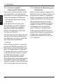
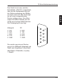
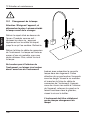
Deutsch
haze-port
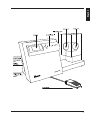
comp-port
Beleuchtungsöffnung
Display
Tastenfeld
Anschlüsse
für:
Netzkabel
Fußschalter
PC
Drucker
(RS 232)
haze
Netzschalter
Netzspannungswahl
Sicherungen
-gard
l
dua
BYK
Fußschalter zur Meßauslösung
59
1 Sicherheitshinweise
1.
Sicherheitshinweise
Deutsch
Es können keine Produkthaftungs- und Gewährleistungsansprüche geltend gemacht werden, wenn das
Gerät nicht entsprechend den
Hinweisen in der Betriebsanleitung und am Gerät betrieben wird.
Bei sachgemäßem Gebrauch
des Gerätes einschließlich des
Zubehörs sind keine Gefahren
zu befürchten, weder mechanischer Art, noch durch elektrischen Strom.
Im folgenden geben wir Ihnen
Hinweise zum sicheren Gebrauch des Gerätes.
Verwenden Sie bitte ausschließlich das für das Gerät
erhältliche Originalzubehör.
Siehe hierzu Lieferumfang und
technische Daten.
Vermeiden Sie andauernde
hohe Luftfeuchtigkeit und
Kondenswasserbildung (siehe
technische Daten). Schützen
Sie das Gerät vor Spritzwasser und Chemikalien.
Führen Sie am Gerät weder
mechanische noch elektrische
Reparaturen durch. Wenden
Sie sich hierzu an unseren
Technischen Kundendienst.
60
An der RS 232 Schnittstelle dürfen nur Geräte angeschlossen
werden, die die Anforderungen
für Sicherheitskleinspannung
erfüllen.
Das Gerät darf nur an Steckdosen mit einwandfreiem Schutzleiter angeschlossen werden.
Bei unzureichender Schutzleiterverbindung kann im Fehlerfall
das Gehäuse des Gerätes berührungsgefährliche Spannungspotenziale annehmen.
Im Zweifelsfall lassen Sie sich
die ordnungsgemäße Ausführung des Schutzleiters in der
Steckdose von einem Fachmann (Elektroinstallateur)
überprüfen.
Das Messgerät wird von der
Versorgung getrennt durch Abziehen des Steckers der Netzanschlussleitung aus der Steckdose. Achten Sie daher auf die
freie Zugänglichkeit des Netzsteckers. Verwenden Sie nur
die mitgelieferte Netzanschlussleitung.
Vor der Inbetriebnahme ist unbedingt zu überprüfen, ob die
am Gerät eingestellte Netzspannung an der Netzeingangskombination mit der Versorgungsspannung der Hausinstallation
übereinstimmt. Siehe hierzu
auch Absatz Aufstellung.
1 Sicherheitshinweise
Deutsch
Fehler und außergewöhnliche
Beanspruchungen.
Wenn anzunehmen ist, dass
ein gefahrloser Betrieb nicht
mehr möglich ist, so ist das
Gerät außer Betrieb zu setzen
und gegen unbeabsichtigtes
Einschalten zu sichern.
Ein gefahrloser Betrieb ist nicht
mehr möglich:
• wenn das Gerät sichtbare Beschädigungen aufweist
• wenn das Gerät nicht mehr
arbeitet
• nach längerer Lagerung unter
ungünstigen Verhältnissen
• nach schweren Transportbeanspruchungen
61
2 Systembeschreibung
Deutsch
2.1
Systembeschreibung
Vor Inbetriebnahme lesen Sie
bitte die Bedienungsanleitung
und beachten Sie die
Sicherheitshinweise.
Das haze-gard dual ist ein stationäres Meßgerät zur Bestimmung des
optischen Erscheinungsbildes von
Glas, Folien, Verpackungen und Teilen aus Kunststoff, sowie anderen
transparenten Materialien. Die Probe wird senkrecht beleuchtet und
das durchgelassene Licht in einer
integrierenden Kugel photoelektrisch gemessen (0°/diffus-Geometrie). Die spektrale Empfindlichkeit ist
an die CIE-Normspektralwertfunktion y unter Normlicht D65
angepasst.
Während bei der unkompensierten
Methode die Oberflächenreflexion
an der Probe ins Meßergebnis eingeht, ist das Ergebnis bei kompensierter Messung unabhängig von
den Reflexionseigenschaften der
Probe (siehe Kap. 11, Meßgrößen).
Das haze-gard dual setzt neue
Maßstäbe im Bereich der Transparenzmeßgeräte. Neben einer
schnellen und einfachen Bedienung
zeichnet es sich durch folgende
Eigenschaften aus:
• Hohe Präzision und Zuverlässigkeit durch Referenzstrahloptik
• Langzeitkalibration und Selbstdiagnose
• Offener Probenraum für kleine
und große Produkte
Die beiden Meßgrößen
• Automatische Kalibration und
menügeführte Bedienung
• Gesamttransmission
(transmittance)
• Geschlossene Optik und
Elektronik
• Trübung (haze)
• Ohne Aufwärmzeit sofort betriebsbereit
erlauben eine objektive Charakterisierung des visuellen Erscheinungsbildes.
Dabei kann zwischen zwei verschiedenen, international genormten
Methoden umgeschaltet werden:
• Kompensiert (ISO 13468 und
14782)
• Unkompensiert (ASTM D1003)
62
• Fußschalter
• Statistikfunktionen im Gerät
• Meßwertspeicher, PC-Schnittstelle, Druckerausgang
3.1
Wichtige Hinweise vor der
Inbetriebnahme:
Vor Inbetriebnahme lesen Sie bitte
die Bedienungsanleitung und
beachten Sie besonders die
Sicherheitshinweise in Kapitel 1.1.
Das Gerät ist auf keine besonderen
Umgebungsbedingungen angewiesen, jedoch sollten die für elektronische Meßgeräte üblichen Betriebsbedingungen eingehalten werden.
Vermeiden Sie:
• übermäßige Schwingungen und
Vibrationen
• extreme Umgebungstemperaturen und schnelle Temperaturänderungen
• Luftfeuchtigkeit über 85% bzw.
Spritzwasser oder ähnliches
• ätzende oder explosive Chemikalien, Dämpfe und Gase
• extreme elektromagnetische
Felder
Das Gerätegehäuse ist gegen eine
Reihe von Lösemitteln beständig,
jedoch kann eine Beständigkeit
nicht für alle Chemikalien gewährleistet werden. Benutzen Sie deshalb zur Reinigung ein weiches
feuchtes Tuch. Bei grober Verschmutzung kann auch Spiritus
oder Seifenlauge verwendet werden. Die Frontlinse am Lichtaustritt
ist mit einem weichen, staubfreien
Tuch zu reinigen (vorzugsweise
feuchte Optiktücher).
Auf keinen Fall das Innere der
Detektorkugel (haze-port) reinigen!
Sollte eine Störung an dem Meßgeräte auftreten, so bitten wir Sie,
keine eigenständigen Reparaturversuche durchzuführen. Unser
technischer Kundendienst wird
Ihnen gerne und schnellstens
weiterhelfen.
• das Eindringen von Fremdkörpern
in die Meßöffnungen
63
Deutsch
3 Inbetriebnahme
3 Inbetriebnahme
Aufstellung
Die Steckverbindungen (Fußschalter, Druckerkabel und Netzkabel) dürfen nur bei ausgeschaltetem Gerät gekoppelt oder auch
wieder getrennt werden !
Für den bestimmungsgemäßen
und sicheren Gebrauch des
Meßgerätes ist die richtige Einstellung der Netzspannung
erforderlich!
• Gerät auspacken und auf eventuelle Transportschäden untersuchen (Sichtprüfung).
• Vor Inbetriebnahme die Lieferung
auf Vollständigkeit überprüfen
(Lieferumfang siehe Kap. 15
Lieferhinweise).
• Eingestellte Netzspannung am
Gerät überprüfen und gegebenenfalls auf die vorhandene Netzspannung einstellen. Ziehen Sie
dazu den Sicherungseinsatz
unterhalb der Netzkabelbuchse
mit einem geeigneten Werkzeug
heraus (Schraubendreher Nr. 2)
und stecken Sie ihn so ein, daß
die Markierung am Netzschaltergehäuse mit der des benötigten
Spannungsbereichs übereinstimmt.
64
USE ONLY WITH 250V
FUSES/EMPLOYER
UNIQUEMENT AVEC
DES FUSIBLES DE 250V
110 - 120V"
Deutsch
3.2
220 - 240V "
T 1,6 A
T 1,0 A
250V ( 115V Mode )
250V ( 230V Mode )
• Beiliegendes Netzkabel mit dem
ausgeschalteten Gerät und einer
Steckdose mit Schutzkontakt
verbinden.
• Falls erforderlich: Fußschalter,
sowie Verbindungskabel zum
Drucker oder PC an den entsprechenden Buchsen anschließen.
SchnittSchnittstelle
Stelle
(RS
232)
(RS 232)
Fußschalter
Fuß-
Schalter
3 Inbetriebnahme
3.3
Einschalten
Deutsch
Bevor Sie das Gerät einschalten,
entfernen Sie bitte die Abdeckungen
von den Messöffnungen. Schalten
Sie das Gerät mit dem Netzschalter
an der linken Seite ein.
Nach dem Einschalten durchläuft
das Gerät verschiedene Selbsttests,
deren Verlauf Sie am Display
verfolgen können.
Es erscheint zunächst das Firmenlogo, sowie die Versionsnummer
der Software zusammen mit dem
Copyrightvermerk.
Versionsnummer und die Jahreszahl
des Copyrights sind für den Kundendienst wichtig, falls Sie einmal
Probleme mit dem Gerät haben
sollten.
Als nächstes führt das Gerät einen
Selbsttest durch. Es werden Lampe,
Chopper und Shutter überprüft.
Liegt eine dieser Komponenten
außerhalb des Toleranzbereichs,
wird ein Fehler angezeigt.
Bei defekter Lampe wird der
Selbsttest angehalten. Wechseln
Sie in diesem Fall die Lampe aus
(Kapitel 12). Sollte für andere
Komponenten ein Defekt angezeigt
werden, setzen Sie sich bitte mit
unserem Service in Verbindung.
"# !&"$
!
!!"
%$$"
!
!!"
%$$"
$
65
3 Inbetriebnahme
Die nächste Displayanzeige ist die
Statusanzeige der gespeicherten
Kalibrierwerte.
STATUS
Die Statusanzeige von Lampenzustand und Kugelbeschichtung gibt
Auskunft über die Abnutzung. Falls
der Lampenzustand unter 50% liegt,
sollte diese gewechselt werden
(Kapitel 12). Ist die Kugelbeschichtung unter 50% abgesunken, wird
eine Prüfung durch den technischen
Kundendienst empfohlen.
STATUS
Die Statusanzeige “Statistik-Speicher” gibt Auskunft über die Anzahl
der im Gerät gespeicherten Meßwerte.
STATISTIK-SPEICHER
Deutsch
Transmission std.
100.0%
66
Lampenzustand
100%
Kugelbeschichtung
100%
Zeit:
12.55
Datum:
28.05.1999
T:
H:
T&H:
n=
n=
n=
4
5
7
3 Inbetriebnahme
WARM-UP
0%
100%
Deutsch
Es folgt eine kurze Warmlaufphase
von ca. 2 Minuten. Das Display
informiert über den zeitlichen Stand
innerhalb dieser Phase.
Sobald das Meßgerät den Selbsttest und die Statusanzeigen abgeschlossen hat, schaltet es in den
beim letzten Betrieb verwendeten
Meßmodus und ist betriebsbereit.
Der Auslieferzustand des Gerätes
ist die ISO-Methode (kompensierte
Messung). Bevor Sie nach der
ersten Inbetriebnahme mit den
Messungen beginnen können, muss
das Gerät kalibriert werden (Kap. 6).
T
ISO
H
67
4 Bedienelemente
4.1
Gerät
haze-port
comp-port
Beleuchtungsöffnung
Tastenfeld
Deutsch
Display
Anschlüsse
für:
Netzkabel
Fußschalter
PC
Drucker
(RS 232)
h a ze
Netzschalter
Netzspannungswahl
Sicherungen
-gard
dua
l
BYK
Fußschalter zur Meßauslösung
Das Display
dient zur Anzeige der Meßwerte und
zum Dialog im SET-UP Menü.
Das Tastaturfeld
dient zur Auswahl und Eingabe.
Die Beleuchtungsöffnung
beleuchtet die Probe zur Messung.
An den haze-port
werden die Proben zur Messung
angelegt.
Der comp-port
dient zur Kompensation bei der
ISO-Meßmethode.
68
Die seitlichen Anschlüsse
dienen zur Verbindung mit der
Netzspannung, dem Fußschalter,
dem PC und dem Drucker.
Mit dem Netzschalter
schalten Sie das Gerät ein. Er dient
auch als Spannungswähler und
Sicherungshalter.
Mit dem Fußschalter
können Sie die Meßvorgänge auslösen, wenn Sie beide Hände zum
Halten der Probe brauchen.
4 Bedienelemente
4.2
Tastatur
Meß- und Auswahltaste
Cursortasten
Deutsch
Referenzmessung
(Dauermessung)
delete last
statistic
result
on/off
on/off
operate
set up
reference
transmittance
haze
transm.
+ haze
delete all
SET-UP Menü
Messgröße umschalten
Die Meß- und Auswahltasten dienen
zur Auslösung der Messung und zur
Auswahl des Meßverfahrens.
transm.+ haze wählt beide Meßverfahren zugleich aus. Mit der
operate
kann man das “SET-UP Menü”
aufrufen. Die
löst eine Messung aus.
reference löst im Modus Dauermessung eine Referenzmessung
aus.
transmittance wählt das Meßverfahren Transmissions-Messung
aus.
haze wählt das Meßverfahren
Haze-Messung aus.
set up - Taste
Cursortasten
bewegen die
Indexmarke
im Menü zur
Anwahl von
Menüpunkten.
operate bestätigt die Auswahl.
set up bricht den Vorgang ab.
69
5 Wahl der Meßmethode
5.1
Wahl der Meßmethode
Deutsch
Bei dem Meßgerät kann zwischen
zwei genormten Meßmethoden
umgeschaltet werden.
• Kompensiert (ISO 13468 und
14782)
T
• Unkompensiert (ASTM D1003)
H
ASTM
Die eingestellte Meßmethode wird
im Display oben rechts angezeigt.
Das Ändern der Meßmethode
erfolgt im “SET-UP Menü”.
delete last
Um in dieses Menü zu gelangen,
wird nur der nebenstehend abgebildete Teil der Tastatur benötigt.
Mit der Taste “set up” wird das Menü
geöffnet.
Für die Bedienung innerhalb des
“SET-UP Menüs” sind nur die
Cursortasten, sowie die Tasten
“operate” und “set up” erforderlich.
Die zusätzliche Beschriftung der
Cursortasten ist hier ohne Bedeutung.
70
statistic
result
on/off
on/off
operate
set up
delete all
SET UP BEDIENUNG
Cursor:
Aendern:
Weiter:
$#!"
OPERATE
"
5 Wahl der Meßmethode
Mit der Cursortaste öffnen Sie das
“SET-UP Menü”.
Zur Wahl der Meßmethode bringen
Sie die Markierung mit den Cursortasten auf den Menüpunkt “Methode” und drücken die Taste “operate”.
Die angezeigte Methode wechselt
und es erscheint ein Hinweis bezüglich des “comp-port”:
SET UP MENUE
Kalibrieren
Statistik drucken
Online Druck:
ein
Dauermessung:
aus
Sprache:
D
Methode:
ISO
Abbruch:
SET UP
Deutsch
Im Display erscheint der erste Teil
des “SET-UP Menüs”.
ASTM
• Wechsel zu ASTM:
comp-port mit Abdeckkappe
verschließen.
Achtung!
comp-port mit
Weißstandard
verschleißen
Weiter:
OPERATE
Achtung!
comp-port
muß
offen sein!
• Wechsel zu ISO:
Abdeckkappe vom comp-port
entfernen.
Weiter:
ISO
OPERATE
Unmittelbar danach beginnt das
Gerät mit der entsprechenden
Kalibrierroutine.
71
6 Kalibrierung
Deutsch
6.1
Kalibrieren
Aufgrund neuer Technologien und
dem Referenzstrahlprinzip ist die
Kalibrierung nur noch selten erforderlich. Als Richtlinie wird ein Kalibrationsintervall von zwei Monaten
empfohlen.
Außerdem ist die Kalibration nötig
• bei der ersten Inbetriebnahme
• bei starker Änderung der
Umgebungstemperatur (z. B. nach
Standortwechsel)
• wenn das Gerät Sie zum Kalibrieren auffordert (z. B. nach dem
Ändern der gespeicherten
Kalibrierwerte)
• nach dem Wechsel der Methode
6.2
Durchführung der
Kalibration
Die Kalibration erfolgt im “SET-UP
Menü”, mit der Taste “set up” wird
dieses Menü geöffnet. Wählen Sie
mit den Cursortasten den Menüpunkt Kalibrieren aus und drücken
Sie die Taste “operate”. Zunächst
erfolgt die Dunkelmessung. Decken
Sie den “haze-port” mit dem Dunkelstandard ab und bestätigen Sie mit
der Taste “operate”.
Durch Drücken der Taste “set up”
können Sie die Kalibrierung abbrechen.
72
KALIBRIERUNG
Dunkelmessung
ISO
Bitte haze-port
abdecken
Bereit:
Abbruch:
OPERATE
SET UP
6 Kalibrierung
Während der Meßvorgang läuft,
erscheint der entsprechende Hinweis im Display.
Messung
Es schließt sich die Hellmessung
an. Dazu entfernen Sie den Dunkelstandard vom “haze-port” und
drücken Sie die Taste “operate”.
KALIBRIERUNG
Hellmessung
Bitte haze-port
freimachen
Bereit:
Das Gerät führt die Hellmessung
durch und kehrt anschließend in
die Meßbereitschaft zurück. Die
Kalibrierung ist jetzt beendet und
das Gerät ist meßbereit.
6.3
ISO
T
OPERATE
ISO
H
Kalibrierung mit anderen
Standards
In der Meßmethode ASTM kann
das Gerät auch mit einem Referenzstandard kalibriert und überprüft
werden (siehe Zubehör / Lieferumfang). Dazu müssen vorab die
Kalibrierdaten dieses Standards im
SET-UP Menü eingegeben werden
(Kap. 10.12). In diesem Fall ist bei
der Kalibration der entsprechende
Standard am “haze-port” anzulegen.
73
Deutsch
aktiv
6 Kalibrierung
Deutsch
Zur Dunkelmessung decken Sie den
“haze-port” mit dem Dunkelstandard
ab und bestätigen mit der Taste
“operate”.
ASTM
Bitte haze-port
abdecken
Abbruch:
Es schließt sich die Hellmessung
an. Dazu entfernen Sie den Dunkelstandard vom “haze-port” und
drücken sie die Taste “operate”.
KALIBRIERUNG
Hellmessung
Bitte achten Sie darauf, daß der
während der Kalibration angezeigte
Wert mit den Angaben des verwendeten Standards übereinstimmt, um
eine Verwechslung auszuschließen.
Um eine exakte Kalibrierung zu
gewährleisten, dürfen nur Originalstandards des Herstellers verwendet werden.
74
ASTM
Bitte haze-port
freimachen
Bereit:
Schließlich werden Sie aufgefordert,
den Standard anzulegen, der im
SET-UP eingetragen wurde. Nach
Drücken der Taste “operate” ist die
Kalibrierung abgeschlossen, das
Gerät ist meßbereit.
OPERATE
OPERATE
KALIBRIERUNG
Transm.Standard
90.0
an haze-port
anlegen
Bereit:
Abbruch:
OPERATE
SET UP
6 Kalibrierung
Zusatzstandards zur
Prüfmittelüberwachung
Um die korrekte Funktion des Meßgerätes zu prüfen, sollten in regelmäßigen Abständen Messungen mit
speziellen Prüfstandards durchgeführt werden.
Entsprechende Prüfstandards sind
in den Lieferhinweisen aufgeführt.
Die angezeigten Meßwerte sollten
innerhalb der angegebenen Werte
des Standards liegen.
Ist das nicht der Fall, dann prüfen Sie
bitte, ob der Standard verschmutzt ist
oder das Gerät nicht richtig kalibriert
ist. Wenn eine Reinigung des Standards und eine erneute Kalibrierung
keine Abhilfe schaffen, dann nehmen
Sie bitte Kontakt zu unserem technischen Kundendienst auf. Bezüglich
der Reinigung beachten Sie bitte die
besonderen Hinweise in Kapitel 6.7.
6.5
Prüfmittelüberwachung
Unter normalen Laborbedingungen
und sorgsamer Handhabung wird ein
Intervall von einem Monat für die
Prüfmittelüberwachung empfohlen.
Wenn die Prüfbedingungen eine
häufigere Gerätekontrolle erfordern,
sollten zwei Haze-Standardsätze
verwendet werden:
1. Arbeits-Standards
Zur Routineprüfung des Geräts kann
jedes Material verwendet werden,
das genügend homogen und zeitlich
stabil ist.
Die Arbeits-Standards werden auf
Primär-Standards bezogen.
2. Primär-Standards
Die Primär-Standards sind nicht für
tägliche Prüfungen gedacht, sondern ausschließlich als Referenzmaterial zur Prüfung der ArbeitsStandards. Wegen der Gefahr der
Beschädigung sind Primär-Standards möglichst selten zu verwenden. Um eine exakte Kalibrierung zu
gewährleisten, dürfen nur Originalstandards des Herstellers verwendet werden.
6.6
Aufbewahrung und
Handhabung von Standards
Die Meßgenauigkeit wird durch die
Verwendung beschädigter oder
verschmutzter Standards erheblich
beeinträchtigt. Achten Sie darauf,
daß die Standards sauber und
kratzerfrei sind.
Die Oberflächen der Standards sind
sehr empfindlich. Daher sollten Sie
die Oberflächen der Standards nicht
berühren und vor Verkratzen schützen (Lagerung unter Verschluss).
Bezüglich der Reinigung beachten
Sie bitte die besonderen Hinweise in
Kapitel 6.6.
Die Standards dürfen keinem direkten Sonnenlicht ausgesetzt und nicht
in schmutziger oder staubiger Umgebung aufbewahrt werden. Schützen Sie die Standards vor Chemikalien und aggressiven Dämpfen.
75
Deutsch
6.4
6 Kalibrierung
Deutsch
6.7
Reinigung
Die Oberflächen der Standards sind
sehr empfindlich. Deshalb sollten
die Standards möglichst selten gereinigt werden. Falsche Meßwerte
können oft schon allein von Staub
und Flusen herrühren. Daher sind
die Standards zunächst mit ölfreier
Druckluft abzublasen.
Standards nie trocken abreiben!
Kratzgefahr durch Scheuerwirkung von Staub.
Die Reinigung muss mit größter
Vorsicht erfolgen. Verwenden Sie
dazu ein frisches, weiches Tuch
und waschen Sie die Standards in
destilliertem Wasser. Dabei keinen
Druck ausüben und nicht scheuern.
Achten Sie darauf, daß an dem
Tuch keine Partikel haften, die die
Oberfläche verletzen könnten.
Verwenden Sie keine aggressiven
Stoffe wie Lösemittel, Spiritus, Trichlorethylen, Benzol, starke Alkohole oder starke Säuren und Laugen.
Chemische Reinigungs- und Politurmittel sind ebenfalls schädlich.
Bei hartnäckiger Verschmutzung
kann dem Wasser auch ein mildes
Haushaltsspülmittel (essigfrei)
zugegeben werden. In destilliertem
Wasser nachspülen.
Mit ölfreier Druckluft trocknen und
Staub oder Fasern wegblasen.
Nie trocken abreiben! Kratzgefahr
durch Scheuerwirkung von Staub.
76
6.8
Gültigkeit der
Standardwerte
Die Meßwerte der Standards können sich, selbst bei schonender
Behandlung, durch Umwelteinflüsse
mit der Zeit ändern. Daher sollten
Sie die Primär-Standards regelmäßig durch den Hersteller vermessen lassen.
Hierfür wird ein jährliches Prüfintervall empfohlen.
7 Messung
ISO-Methode
Die Meßgröße “transm.haze” ist
ausgewählt, das Gerät ist meßbereit
nach ISO. Der comp-port ist offen.
Drücken Sie die Taste “operate”. Das
Gerät fordert Sie auf, die Probe an
den comp-port anzulegen.
Probe an
comp-port
anlegen
Bereit:
OPERATE
Die Probe muss während der Messung plan an der Öffnung anliegen.
Drücken Sie die Taste “operate”. Das
Gerät beginnt mit der Messung.
Während der Messung erscheint die
Anzeige
“Messung aktiv”.
Anschließend werden Sie aufgefordert, die Probe an den “haze-port”
anzulegen.
Legen Sie die Probe an den “hazeport” an und drücken Sie die Taste
“operate”.
Probe an
haze-port
anlegen
Bereit:
OPERATE
Wiederum erscheint die Anzeige
“Messung aktiv”.
Das Ergebnis erscheint, der
Meßvorgang ist abgeschlossen.
Die Transmissionsmessung allein ist
vom Ablauf her identisch wie der
oben beschriebene Meßvorgang.
T
H
91.8
18.3
ISO
77
Deutsch
7.1
7 Messung
Deutsch
7.2
ASTM Methode
Die Meßgröße “transm.+haze” ist
ausgewählt, der comp-port ist mit
der Abdeckkappe verschlossen, das
Gerät ist meßbereit nach ASTM.
Legen Sie Ihre Probe an den “hazeport” an und drücken Sie die Taste
“operate”.
transm.
+ haze
Es erscheint die Meldung
“Messung aktiv”.
Messung
aktiv
Das Meßergebnis erscheint im
Display, die Messung ist abgeschlossen.
Die Transmissionsmessung allein ist
vom Ablauf her identisch wie der
oben beschriebene Meßvorgang.
7.3
H
Haze-Messung
Wenn nur die Meßgröße Haze
gewählt wird, so ist der Ablauf bei
den Methoden ISO und ASTM
identisch. Legen Sie die Probe an
den “haze-port” an und drücken
“operate”. Nach dem Hinweis
“Messung aktiv” wird das Ergebnis
angezeigt.
78
T
haze
91.8
18.3
ASTM
8 Messreihen mit Statistik
Meßreihen mit Statistik
Die Statistikfunktion kann zu allen
Meßgrößen allein oder in Kombination aufgerufen werden. Die Statistikfunktionen werden mit den Cursortasten “Links/Rechts” aufgerufen. In
diesem Fall ist die Bezeichnung
ober-, und unterhalb der Tasten
gültig.
Im Modus Dauermessung kann die
Statistik nur für eine Meßgröße
betrieben werden.
Mit der Taste “statistic on/off” schalten Sie die Statistikfunktion zur
bestehenden Darstellung der
Meßwerte hinzu.
Auf dem Display erscheinen
zusätzlich:
n
=
Anzahl der Messungen
m
=
Mittelwert
s
=
Standardabweichung
statistic
result
on/off
on/off
Deutsch
8.1
T
H
91.8
18.3
STATISTIK
T
H
90.8
18.3
ASTM
ASTM
n= 14
m= 91.6
s= 1.2
m= 17.0
s= 1.8
79
8 Messreihen mit Statistik
Deutsch
Mit der Taste “result on/off” können
alle Statistikdaten eingeschaltet
werden.
act = Zuletzt gemessener Wert,
bei Dauermessung Wert
der eingelegten Probe
m = Mittelwert
min = kleinster Wert
max = größter Wert
s
= Standardabweichung
v
= Varianz
RESULT
act=
m=
min=
max=
s=
v=
Die Meßwerte im Statistik-Modus
werden gespeichert und bleiben
beim Umschalten der Meßgrößen
oder Abschalten des Geräts erhalten. Die gespeicherten Werte
können über die serielle Schnittstelle an einen Drucker oder PC übertragen werden. Eine früher aufgenommene Meßreihe kann, solange
sie nicht gelöscht wurde, bei erneutem Aufruf fortgesetzt werden.
Während einer laufenden Meßserie
dürfen die Kalibrierwerte nicht
geändert werden, da dies die
statistischen Ergebnisse verfälscht.
8.3
8.2
8.4
Statistik bei Dauermessung
Im Modus Dauermessung werden
Meßdaten zwar dauernd angezeigt,
aber nicht automatisch gespeichert.
Um eine Messung der Meßreihe
hinzuzufügen, muss die Taste
“operate” gedrückt werden.
80
T
90.8
90.6
87.2
91.3
1.02
1.12
S=
H
8.79
8.14
6.93
9.79
0.71
8.77
ASTM
n= 14
n
2
1
(x -x)
n-1 i=1 i
V = 100 x s / m %
Messung löschen
Die Taste “delete last” löscht
die letzte gespeicherte Messung.
delete last
Die Zählvariable n wird um 1
herabgesetzt.
Alle löschen
Die Taste “delete all” löscht
alle Meßwerte dieser Meßreihe.
Die Löschfunktion bezieht
sich nur auf den Speicherbereich der momentan eingestellten Meßgrößen.
delete all
Während Sie im normalen Meßmodus
die einzelnen Messungen mit der
Taste “operate” oder mit dem Fußschalter auslösen, wird die Probe im
Modus “Dauermessung” ständig gemessen und das Ergebnis fortlaufend
im Display angezeigt. Auf diese Weise
ist es möglich, eine Probe abzufahren
und somit auf mögliche Inhomogenitäten zu überprüfen.
Die Funktion “Dauermessung” kann
nur für eine Meßgröße gewählt
werden. Sollten Sie versuchen, bei
den Meßgrößen “transm.+haze” in
den Dauermeßmodus umzuschalten,
erhalten sie die nebenstehende
Warnung angezeigt.
Deutsch
9 Dauermessung
Dauermessung
nur
im
Einzelmessmodus
möglich
Wählen Sie eine Meßgröße und
schalten Sie dann im Menü “SET-UP”
mit der Taste “operate” die Dauermessung ein.
9.1
Dauermessung ISO
Transmittance
Die Transmissionsmessung benötigt
eine Kompensationsmessung als
Referenz. Im Display erscheint die
Aufforderung zur Bestimmung der
Kompensation.
Legen Sie Ihre Probe an den “compport” an und drücken Sie die Taste
“operate”.
Es erscheint die Anzeige “Messung
aktiv” im Display, anschließend beginnt das Gerät mit der Dauermessung. Legen Sie die Probe an den
“haze-port”, die Meßwerte werden
fortlaufend angezeigt.
Bestimmung der
Compensation
Probe an
comp-port
anlegen
Weiter:
DAUERMESSUNG
T
90.8
OPERATE
ISO
81
9 Dauermessung
Um einen Meßwert der Statistik
hinzuzufügen, drücken Sie die Taste
“operate”. Im Display erscheint die
Anzeige:
Deutsch
Messung aktiv.
Anschließend kehrt das Gerät zur
Dauermessung zurück.
Bei eingeschalteter Statistikfunktion
(Kap. 8.3) sehen Sie, daß der Zähler
nach der Messung um eine Einheit
heraufgesetzt wurde.
reference
Wenn Sie das zu messende
Material wechseln, ist eine erneute
Kompensation nötig. Lösen Sie den
Wechsel mit der Taste “reference”
aus.
Sie werden aufgefordert, die Probe
an den comp-port anzulegen. Mit
der Taste “operate” lösen Sie die
Kompensationsmessung aus.
Anschließend kehrt das Gerät zur
Dauermessung zurück.
Haze
Die Hazemessung benötigt den
Wert der Gesamttransmission als
Referenz für die gemessene Probe.
Darauf werden Sie gegebenenfalls
im Display hingewiesen. Legen
Sie die Probe zur Bestimmung der
Gesamttransmission an den “hazeport” an.
Anschließend kehrt das Gerät zur
Dauermessung zurück.
82
*+#%%,&! )
'%( &*+#'&
)' &
'%((')+
&$ ! &
#+ )
*+#%%,&! )
)&*%#**#'&
)' &
"- (')+
&$ ! &
#+ )
&
%
*
9 Dauermessung
Um einen Meßwert der Statistik
hinzuzufügen, drücken Sie die Taste
“operate”. Im Display erscheint die
Anzeige:
Deutsch
Messung aktiv.
Anschließend kehrt das Gerät zur
Dauermessung zurück.
Wenn Sie das zu untersuchende
Material wechseln, ist eine erneute
Bestimmung der Transmission
notwendig.
reference
Mit der Taste “reference” lösen Sie
den Wechsel aus.
Das Gerät fordert Sie auf, die Probe
an den “haze-port” anzulegen.
Anschließend kehrt das Gerät zur
Dauermessung zurück.
Standby
Um die Lampe zu schonen, wird die
Dauermessung nach einer gewissen
Zeit unterbrochen, falls das Gerät
im Strahlengang keine Änderung
des Meßwertes mehr feststellen
kann. Der Standby-Modus wird im
Display angezeigt.
DAUERMESSUNG
T
89.5
ISO
Standby-Modus
Die Messung wird fortgesetzt, wenn
sich im Strahlengang eine signifikante Änderung ergibt (z. B. Anlegen einer Probe).
83
9 Dauermessung
Deutsch
9.2
Dauermessung ASTM
Transmittance
Die Umschaltung in den Dauermeßmodus in der Meßmethode
ASTM erfolgt genauso wie bei ISO,
mit dem Unterschied, daß der
comp-port mit der Abdeckkappe
verschlossen sein muss, worauf Sie
gegebenenfalls hingewiesen werden. Die Bestimmung der Kompensation entfällt.
Ein Wechsel des zu untersuchenden Materials erfordert keinerlei
Vorkehrungen. Die Speicherung des
Meßwerts erfolgt durch Drücken der
Taste “operate”.
Haze
reference
Bei der Meßgröße Haze ist die Messung der Transmission notwendig.
Sie wird im Display zusätzlich angezeigt. Mit der Taste “reference”
lösen Sie die Neubestimmung der
Transmission aus.
Das Gerät fordert Sie auf, die Probe
an den “haze-port” anzulegen.
Das Gerät führt die Messung mit der
neuen Referenz durch. Anschließend wird der Hazewert im Display
angezeigt. Dazu erscheint der dazugehörige Transmissionswert in der
rechten oberen Ecke des Displays.
84
DAUERMESSUNG
H
13.4
T:
ASTM
86.4
9 Dauermessung
9.3
Deutsch
Die Speicherung eines Meßwertes,
sowie das Zurückschalten in den
Standby-Modus, erfolgen genauso,
wie unter Dauermessung ISO
beschrieben.
Dauermessung Statistik
Im Modus Dauermessung kann
ebenfalls eine statistische Auswertung der Meßwerte vorgenommen
werden. Die gemessenen Werte
werden in den gleichen Speicherbereich geschrieben wie im normalen Meßbetrieb.
Schalten Sie mit den Tasten
statistic
“statistic” :
on/off
oder
result
“result” :
on/off
die gewünschte Funktion ein. Sie
wird im Display dargestellt.
Sie können nun die gewünschte
Stelle Ihrer Probe anfahren und die
Entwicklung der Meßwerte auf dem
Display verfolgen. Möchten Sie
einen Wert speichern, so geschieht
dies durch Drücken der Taste
“operate” oder durch Betätigen des
Fußschalters.
DAUERMESSUNG
H
12.7
T:
n=
m=
s=
ASTM
89.4
11
10.6
1.16
85
10 SET-UP
Deutsch
10.1 Allgemeines
Im SET-UP Menü können Sie verschiedene Geräteparameter einstellen, die Sprache wählen, sowie die
Kalibration durchführen.
Der Aufruf des SET-UP Menüs, und
die Einstellungen im Menü selbst,
werden mit dem nebenstehend
abgebildeten Teil der Tastatur vorgenommen.
Drücken Sie die Taste “set up”, um
das SET-UP Menü aufzurufen.
Es erscheint ein Hinweis zur Bedienung im Display.
Mit den Cursortasten “Auf”/"Ab"
wählen Sie die einzelnen Menüpunkte, bzw. Menüseiten an.
delete last
statistic
result
on/off
on/off
operate
delete all
SET UP BEDIENUNG
Cursor:
Aendern:
$#!"
OPERATE
"
Weiter:
Drücken Sie die Taste:
Es erscheint die erste Menüseite mit
den nebenstehenden Auswahlpunkten.
Wenn Sie nun mit der Taste:
die Markierung durch das
Menü abwärts bewegen, erscheint die zweite Seite des
SET-UP Menüs.
Wählen Sie nun den Menüpunkt aus,
den Sie verändern möchten, indem
Sie die Markierung auf den Punkt
bewegen. Drücken Sie die Taste
“operate” zum Ändern oder “set up”
zum Abbruch.
Abgebildet ist das Menü in der Einstellung ASTM. In der Einstellung ISO
entfällt der Punkt “Kalib.Std. ändern".
86
set up
SET UP MENUE
Kalibrieren
Statistik drucken
Online Druck:
ein
Dauermessung:
aus
Sprache:
D
Methode:
ASTM
Abbruch:
SET UP
SET UP MENUE
Signalton:
Datum ändern
Zeit ändern
Display Kontrast
Kalib.Std. ändern
Abbruch:
SET UP
ein
10 SET-UP
10.2 Kalibrieren
Das Kalibrieren des Gerätes ist
unter Kapitel 6 ab Seite 20 beschrieben.
Markieren Sie den Menüpunkt
“Statistik drucken” und drücken Sie
die Taste “operate”.
Die Meßdaten des gewählten Statistikspeichers werden auf dem angeschlossenen Drucker ausgegeben.
SET UP MENUE
Kalibrieren
Statistik drucken
Online Druck:
ein
Dauermessung:
aus
Sprache:
D
Methode:
ASTM
Abbruch:
SET UP
Deutsch
10.3 Statistik drucken
Statistik ausdrucken
T :
n=
8
Datum:
28.05.1999
Zeit:
12:55
Nummer:
Abbruch:
SET UP
10.4 Online Druck
Markieren Sie den Menüpunkt und
drücken Sie die Taste “operate”, um
die Einstellung zu ändern.
Ist die Funktion “Online Druck” eingeschaltet, werden die Meßdaten
nach jeder Messung direkt an dem
angeschlossenen Drucker ausgegeben.
87
10 SET-UP
Deutsch
10.5 Dauermessung
Wird die Funktion Dauermessung
eingeschaltet, wiederholt das Gerät
den Meßvorgang permanent. Diese
Funktion kann verwendet werden,
um größere Prüflinge auf ihre Homogenität zu überprüfen (vgl. Kap.9).
10.6 Sprache
Um die Sprache zu ändern, bringen
Sie die Markierung auf “Sprache”
und drücken die Taste “operate”.
Es erscheint das Auswahlmenü für
die vorhandenen Sprachen. Die
momentan eingestellte Sprache ist
markiert. Wählen Sie die gewünschte Sprache mit den Cursortasten aus
und drücken Sie die Taste “operate”.
10.7 Methode
Sie können zwischen den Meßmethoden ASTM und ISO wählen.
Die momentan aktuelle Meßmethode ist hinter dem Menüpunkt “Methode” angezeigt. Um die Meßmethode
zu ändern, bringen Sie die Markierung auf “Methode” und drücken Sie
die Taste “operate”.
88
SET UP MENUE
Kalibrieren
Statistik drucken
Online Druck:
ein
Dauermessung:
aus
Sprache:
D
Methode:
ASTM
Abbruch:
SET UP
Deutsch
Englisch
Französisch
Italienisch
Spanisch
Japanisch
Bestätigen:
Abbruch:
OPERATE
SET UP
10 SET-UP
Deutsch
Die angezeigte Meßmethode ändert
sich und das Meßgerät geht unmittelbar danach in die Kalibrierfunktion der ausgewählten Meßmethode
über. Führen Sie nun die Kalibrierung durch (Kap. 6, S. 19).
10.8 Signalton
Das Gerät erzeugt nach jeder abgeschlossenen Messung einen Signalton. Mit dem Menüpunkt Signalton
können Sie das Tonsignal ein- oder
ausschalten.
10.9 Datum ändern
Um das Datum zu ändern, bringen
Sie die Markierung auf “Datum
ändern” und drücken die Taste
“operate”.
SET UP MENUE
Signalton:
Datum ändern
Zeit ändern
Display Kontrast
Kalib.Std. ändern
Abbruch:
Es erscheint das Eingabemenü für
das Datum.
Datum:
Mit den Tasten :
Neues Datum:
tt mm jjjj
17 05 1999
verschieben Sie den Pfeil zu der zu
ändernden Position.
Bestätigen:
Abbruch:
ein
SET UP
17/05/1999
OPERATE
SET UP
Mit den Tasten :
ändern Sie den Wert an
der entsprechenden Stelle.
Jahreszahlen vor 1980 werden nicht angenommen.
89
10 SET-UP
10.10 Zeit ändern
Deutsch
Um die Gerätezeit zu ändern, bringen Sie die Markierung auf “Zeit
ändern” und drücken die Taste
“operate”.
SET UP MENUE
Signalton:
Datum ändern
Zeit ändern
Display Kontrast
Kalib.Std. ändern
Abbruch:
Es erscheint das Eingabemenü für
die Zeit.
Mit den Tasten :
verschieben Sie den Pfeil zu der zu
ändernden Position.
ein
SET UP
Zeit:
15:40
Neue Zeit:
hh:mm
15:45
Bestätigen:
Abbruch:
OPERATE
SET UP
Mit den Tasten :
ändern Sie den Wert an der
entsprechenden Stelle.
10.11 Display Kontrast
Um den Kontrast des Displays zu
ändern, bringen Sie die Markierung
auf “Display Kontrast” und drücken
die Taste “operate”.
SET UP MENUE
Signalton:
Datum ändern
Zeit ändern
Display Kontrast
Kalib.Std. ändern
Abbruch:
Es erscheint die Eingabemaske zur
Kontraständerung.
Mit den Tasten :
stellen sie den Kontrast auf einer
Skala von 1-10 ein. Ein höherer
Wert bedeutet höheren Kontrast.
90
ein
SET UP
Kontrast:
1
Bestätigen:
Abbruch:
10
OPERATE
SET UP
10 SET-UP
10.2 Kalibrierwerte ändern
Dieser Menüpunkt ist nur unter der
Meßmethode ASTM verfügbar.
Führen Sie die Markierung
mit den Cursortasten auf
den Menüpunkt “Kalib.Std.
Ändern”. Drücken Sie die
Taste “operate”.
Wählen Sie “Transmission Std.” und
drücken Sie die Taste “operate”.
Deutsch
Der Wert des Kalibrierstandards ist
im Meßgerät gespeichert. Während
der Kalibrierung werden diese Daten dem jeweiligen Standard zugeordnet. Bei freiem Strahlengang
beträgt die Transmission 100%.
In einzelnen Fällen kann es erforderlich sein, die gespeicherten
Daten einem neuen Standard anzupassen, z. B. wenn Sie hausinterne Standards verwenden, deren
Transmission Ihnen bekannt ist.
Sie können aber auch das Gerät mit
dem als Zubehör erhältlichen
Transmissionsstandardsatz kalibrieren und überprüfen (siehe Kap. 6.2
Kalibrieren mit anderen Standards).
SET UP MENUE
Signalton:
Datum ändern
Zeit ändern
Display Kontrast
Kalib.Std. ändern
Abbruch:
SET UP
Kalibrierstd.
ändern
ein
Transmission Std.
Werte sichern
Abbruch:
SET UP
91
10 SET-UP
Deutsch
Im Display erscheint der zu ändernde
Wert als vierstellige Zahl. Die letzte
Ziffer ist in diesem Fall die Stelle nach
dem Komma.
Wählen Sie mit den
Tasten:
die zu ändernde
Dezimalstelle aus und ändern
Sie deren Wert mit den Cursortasten “Auf / Ab”.
T.Std. =
100
1000
Bestätigen:
Abbruch:
OPERATE
SET UP
Mit der Taste “operate” bestätigen Sie die Änderung. Das
Gerät kehrt zum Menü “Kalibrierstd.
ändern” zurück.
Vorübergehende Speicherung
Wenn Sie nun das Menü “Kalibrierstd.
Kalibrierstd.
ändern
ändern” mit der Taste “set up” = AbTransmission Std.
bruch verlassen, wird der geänderte
Werte sichern
Wert vorübergehend übernommen.
Das Gerät beginnt mit der Kalibrierung. Nach der Dunkel- und der HellAbbruch:
SET UP
messung werden Sie aufgefordert, den
Standard mit dem soeben eingegebenen Wert am “haze-port” anzulegen.
Standards müssen sauber und
Legen Sie den Standard an und
unbeschädigt sein!
drücken Sie die Taste “operate”. Die
Kalibrierung ist beendet und der neue
Transmissionswert ist nun bis zum
Abschalten des Gerätes gespeichert.
Nach dem Wiedereinschalten des
Gerätes erscheint nach dem Firmenlogo nebenstehende Meldung.
Mit dem Betätigen der Taste “operate”
werden die ursprünglichen Daten
wiederhergestellt.
92
Kalibrierdaten
werden berichtigt
Weiter:
OPERATE
10 SET-UP
Um den geänderten Wert eines
Kalibrierstandards dauerhaft im
Gerät zu speichern, bringen Sie im
Menü “Kalibrierstd. ändern” die
Markierung mit den Cursortasten auf den Menüpunkt “
Werte sichern” und drücken
die Taste “operate”.
Es erscheint das “Werte
sichern” Display.
Hier sind nochmals der alte und der
neue Wert gegenübergestellt.
Um den neuen Wert zu sichern,
drücken Sie die Taste “operate”.
Das Gerät beginnt mit der Kalibrierung. Nach der Dunkel- und der
Hellmessung werden Sie aufgefordert, den Standard mit dem
gespeicherten Wert am “haze-port”
anzulegen.
Legen Sie den Standard an und
drücken Sie die Taste “operate”.
Die Kalibrierung ist beendet und der
neue Transmissionswert ist nun
dauerhaft gespeichert.
Kalibrierstd.
ändern
Transmission Std.
Werte sichern
Abbruch:
Deutsch
Dauerhafte Speicherung
SET UP
WERTE
SICHERN
Alt
100
Sichern:
Abbruch:
Neu
90
OPERATE
SET UP
Standards müssen sauber und
unbeschädigt sein!
93
Deutsch
11 Meßgrößen
11.1 Erscheinungsbild
transparenter Materialien
11.2 Kriterien zur Bewertung der
Transparenz
Wenn eine lichtdurchlässige Probe
von gerichtetem Licht beleuchtet
wird, treten je nach Materialbeschaffenheit verschiedene Effekte auf:
Das Erscheinungsbild transparenter
Produkte wird von Glanz, Farbe und
Transparenz bestimmt. Wesentlich
für die Transparenz sind die Größen
Gesamttransmission und Trübung.
• Homogenes Material mit glatter
Oberfläche
Zum Teil wird das Licht an den
Grenzflächen gerichtet reflektiert
und zum Teil geht es ungestört
durch die Probe. Die Probe erscheint hochglänzend und in der
Durchsicht völlig klar.
Die Intensität des durchgelassenen
Lichtes wird durch die Absorption
des Materials und durch Farbstoffe
oder Pigmente geschwächt.
• Trübung
Diffuse Streuung führt zu einer Abnahme der Abbildungsqualität. Als
Streuzentren wirken dabei Teilchen
oder Inhomogenitäten im Material.
An diesen Bereichen wird das Licht
in alle Richtungen gestreut, wobei
auf jeden Raumwinkel nur eine
geringe Streuintensität entfällt.
Dies bewirkt eine Verminderung des
Kontrastes und ein milchig trübes
Erscheinungsbild. Dieser Effekt wird
als Trübung oder Haze bezeichnet.
94
Die Gesamttransmission ist das
Verhältnis des insgesamt durchgelassenen Lichtes zur einfallenden
Lichtmenge. Sie wird reduziert
durch Reflexion und Absorption.
Trübung ist nach ASTM 1003 der
prozentuale Anteil durchgelassenen
Lichtes, der vom eingestrahlten
Lichtbündel im Mittel um mehr als
2,5° abweicht.
Deutsch
11 Meßgrößen
Lichtfalle
Beleuchtung
Probe
comp-port
11.3 Meßprinzip
11.4 Normen
Ein Lichtbündel trifft auf die Probe
und tritt anschließend in eine integrierende Kugel ein. Das von der
mattweißen Kugelwand gleichmäßig
verteilte Licht wird von einem
Detektor gemessen. Die Gesamttransmission wird bei geschlossenem und die Trübung bei geöffnetem Kugelausgang bestimmt.
ASTM D 1003:
Bei der Meßmethode nach ISO
13468 und ISO 14782 wird die
Kugeleffektivität bei der Messung
berücksichtigt.
ISO 13468:
Standard Test Method for Haze and
Luminous Transmittance of Transparent Plastics.
ASTM D 1044:
Standard Test Method for
Resistance of Transparent Plastics
to Surface Abrasion.
Plastics - Determination of the total
luminous transmittance of transparent materials.
ISO 14782:
Plastics - Determination of haze for
transparent materials
95
Deutsch
11 Meßgrößen
ASTM D 1003
Die Meßbedingungen sind während der Kalibration und der aktuellen Messung unterschiedlich.
Während der Kalibration entweicht ein Teil des einfallenden Lichts durch die
offene Eingangsöffnung, während bei der Messung die Eingangsöffnung mit
der Probe verschlossen ist. Dadurch wird die Lichtmenge in der Kugel um
den Anteil vermehrt, der an der Probe reflektiert wird.
Kompensation
Messung
Probe
Mit Kompensation: Gleiche Kugeleffektivität
ISO 13468
Die Meßbedingungen sind durch eine zusätzliche Öffnung in der Kugel
während der Kalibration und der Messung gleich.
Während der Kalibration wird die Probe an die Kompensationsöffnung
angelegt. Bei der Messung wird die Probe an die Meßöffnung angelegt.
Auf diese Weise ist die Kugeleffektivität völlig unabhängig von den
Reflexionseigenschaften der Probe.
Der Unterschied zwischen den beiden Meßmethoden kann bis zu 2% bei
klaren, glänzenden Proben betragen.
96
11.5 Bemerkungen
• Bei Werten kleiner als 10% wird
der Meßbereich automatisch auf
eine Anzeige mit zwei Dezimalstellen umgeschaltet.
• Während der Messung wird über
die ausgeleuchtete Fläche der
Probe gemittelt. Da man nicht
davon ausgehen kann, daß die
optischen Eigenschaften über die
gesamte Fläche des Prüflings
gleichmäßig sind, sollte man an
mehreren Stellen der Probe messen und den Mittelwert verwenden.
• Die Messung an verschmutzten,
verkratzten oder anderweitig gestörten Bereichen des Prüflings ist
nicht sinnvoll, es sei denn, daß
man durch die Messung eine
Aussage über den Grad derartiger
Störungen erzielen will, z. B.
Abriebfestigkeit (Taber Abraser).
• Unterschiedliche Reflexionseigenschaften können die Transparenzmessung beeinflussen. Insbesondere, wenn die Proben von einer
Seite glänzend und von der anderen Seite matt sind, sollte immer
dieselbe Seite in Richtung Kugelöffnung gehalten werden.
• Zur Messung von Flüssigkeiten
können Küvetten mit planparallelen Wänden und optischer Qualität bei einer Größe von mindestens 50 mm Kantenlänge verwendet werden (Kap. 15).
• In der Praxis kann es von Bedeutung sein, ob die Streuung von internen Streuzentren oder von der
Oberfläche verursacht wird. In
diesen Fällen kann die Oberflächenstreuung eliminiert werden,
indem man die Probe in eine Flüssigkeit mit gleichem Brechungsindex taucht. Dadurch kommt allein
die innere Streuung zur Wirkung.
• Die Proben müssen möglichst
planparallele Oberflächen aufweisen. Durch einen Dickenkeil
wird das Licht abgelenkt.
• Bei Vergleichsmessungen sollte
die Dicke der Probe beachtet
werden, da Absorption und Streuung mit der Dicke der Probe
zunehmen.
97
Deutsch
11 Meßgrößen
12 Wartung und Pflege
Deutsch
12.1 Lampenwechsel
Achtung! Schalten Sie zuerst das
Gerät aus und trennen Sie das
Gerät von der Spannungsversorgung, indem Sie den Netzstecker
ziehen. Lassen Sie die Lampe abkühlen, bevor Sie sie wechseln.
Nehmen Sie die Abdeckung oberhalb des Displays ab. Dazu entfernen Sie die oberste der beiden
Schrauben. Drücken Sie auf der
dem Display zugewandten Seite von
oben leicht auf den Deckel, bis er
sich hebt, und entfernen Sie ihn
dann.
Ziehen Sie den Stecker der Zuleitung nach oben aus dem Sockel.
Die Lampeneinheit ist mit einer
Rändelschraube befestigt. Drehen
Sie diese heraus und ziehen Sie
anschließend die Lampeneinheit
zusammen mit der Rändelschraube
aus der Fassung.
Nicht in das Geräteinnere fassen
und keine Gegenstände in die
Geräteöffnung fallen lassen!
Setzen Sie nun die neue Lampeneinheit vorsichtig in die Fassung ein.
Berühren Sie den Glaskörper der
Lampe nicht mit den Fingern.
98
2.
1.
3.
Befestigen Sie die Lampeneinheit
mit der Rändelschraube und verbinden Sie den Stecker der Zuleitung mit dem Sockel am Gerät.
Vergewissern Sie sich, daß keine
Gegenstände im Gerät zurückgeblieben sind, und schließen Sie den
Deckel, indem sie ihn von hinten in
die Führung schieben und mit der
Schraube am Gehäuse befestigen.
Nach dem Lampenwechsel muß
das Gerät neu kalibriert werden.
12 Wartung und Pflege
12.2 Sicherungswechsel
Deutsch
Achtung! Schalten Sie zuerst das
Gerät aus und trennen Sie das
Gerät von der Spannungsversorgung, indem Sie den Netzstecker
ziehen.
Ziehen Sie den Sicherungshalter
mit einem geeigneten Werkzeug
(Schraubendreher Nr. 2) aus dem
Netzsteckergehäuse (linke Seite
des Gerätes). Wechseln Sie die
defekte Sicherung gegen eine neue
aus. Verwenden Sie ausschließlich
den vorgeschriebenen Sicherungstyp (technische Daten, Kap. 14).
Setzen Sie nun den Sicherungseinsatz wieder ein, so daß der Pfeil
neben der verwendeten Netzspannung zur Markierung am Gehäuse
weist.
Verwenden Sie keine anderen
Sicherungen als die des angegebenen Typs. Überbrücken Sie
keinesfalls die Sicherung! Die
Markierung der verwendeten
Netzspannung muß mit der
Markierung am Gehäuse übereinstimmen.
99
12 Wartung und Pflege
Deutsch
12.3 Pflege des Gerätes
Achtung! Schalten Sie zuerst das
Gerät aus und trennen Sie das
Gerät von der Spannungsversorgung, indem Sie den Netzstecker
ziehen.
Das Gerätegehäuse ist gegen eine
Reihe von Lösemitteln beständig,
jedoch kann eine Beständigkeit
nicht für alle Chemikalien gewährleistet werden. Benutzen Sie deshalb zur Reinigung ein weiches,
feuchtes Tuch. Bei grober Verschmutzung kann auch Spiritus
oder Seifenlauge verwendet werden. Reinigen Sie die Frontlinse
am Lichtaustritt nur mit einem
weichen, staubfreien Tuch.
Auf keinen Fall das Innere der
Detektorkugel (haze-port)
reinigen!
Sollte eine Störung an dem Meßgerät auftreten, so bitten wir Sie,
keine eigenständigen Reparaturversuche durchzuführen. Unser
technischer Kundendienst wird
Ihnen gerne und schnellstens
weiterhelfen.
100
13 Schnittstellenbeschreibung
Meßgerät
PC
3
2
7
8
5
3
2
5
4
7
TxD
RxD
RTS
CTS
GND
Deutsch
Das Gerät ist mit einer seriellen
Schnittstelle ( RS-232 ) ausgerüstet,
über die die Gerätesteuerung und
die Weiterverarbeitung der Meßdaten durch einen PC oder die Ausgabe auf einem entsprechenden
Drucker erfolgen kann. Zum Übertragen der Daten befindet sich am
Gerät eine 9-polige SUB-D Buchse.
Die Pinbelegung ist wie folgt:
1
RxD
TxD
CTS
RTS
GND
6
9
Die serielle asynchrone Übertragung ist im Meßgerät festgelegt und
findet nach folgendem Format statt:
5
9600 Baud, 8 Datenbits, no parity,
1 Stopbit.
101
Deutsch
14 Technische Daten
Meßgeometrie:
0°/diffus
Meßöffnung:
21,0 mm
Meßfeld:
16,5 mm
Farbempfindlichkeit:
In spektraler Anpassung an CIE
Normspektralwertfunktion y
unter Normlichtart D65
Meßbereich:
Transmission:
Haze:
0–100%
0–100%
Netzspannung:
230 V/50 Hz,
115 V/60 Hz
Leistungsaufnahme:
max. 200 VA
Sicherung:
250 V
Träge 1,0 A;
(230 V Netzspannung)
Träge 1,6 A; 250 V
(115 V Netzspannung)
Betriebstemperatur:
+ 10 °C bis
+ 40 °C
Lagertemperatur:
0 °C bis +50 °C
von 10,0 bis 99,9
Maße:
39 x 67 x 24 cm
Wiederholbarkeit:
± 0,1 Einheiten*
Gewicht:
18 kg
Vergleichbarkeit:
± 0,4 Einheiten*
Meßzeit:
1 bis 6 Sekunden
(je nach Modus)
Statistikspeicher:
3 x 999 Meßwerte,
batteriegepuffert
Lithiumzelle 3 V
(CR 2450N FH)
Schnittstelle:
seriell RS-232
dialogfähig
Auflösung
der Anzeige:
Anschlüsse:
RS-232:
Fußschalter:
102
0,01 im Bereich
von 0,00 bis 9,99
0,1 im Bereich
9-polig Sub-D
15-polig Sub-D
*Standardabweichung
Technische Änderungen
vorbehalten
15 Lieferhinweise
Bestell-Nr.
haze-gard dual
Grundversion
bestehend aus:
s -EGERËT
s 3CHNITTSTELLENKABEL
für Anschluss an PC
oder Drucker
s 3OFTWAREEASYLINK
s &USCHALTER
s !BDECKKAPPE
s $UNKELSTANDARD
s &OLIENHALTER
(6 cm und 12 cm)
s .ETZKABEL
Lieferumfang
s 3ERIELLERTRAGBARER
40 Zeichen Drucker
230 V
s (ALTERFàR4ABER
Abriebprobe
!4 s ,AMPE
s (ALTERFàR+àVETTEN
AT-4727
Bestell-Nr.
!4
!4
!4
!4
!4
Küvetten, 50 mm Kantenlänge:
s 7EGLËNGEMM
!4
s 7EGLËNGEMM
!4
s 7EGLËNGEMM
!4
s 7EGLËNGEMM
!4
Zubehör
Haze-Prüfstandards:
s (AZECA 1 %
s (AZECA 5 %
s (AZECA
s (AZECA
s (AZECA
s 3ATZMIT3TàCK
AT-4760
AT-4761
!4
!4
!4
!4
Transmission standards:
s 4RANSMISSIONCA
s 4RANSMISSIONCA
s 4RANSMISSIONCA
s 4RANSMISSIONCA
s 3ATZMIT3TàCK
!4
!4
!4
!4 Für die Gewährleistung gelten die
!4 allgemeinen Geschäftsbedingungen
103
Deutsch
Lieferumfang
16 Fehlermeldungen
Ursache
Deutsch
Der aktuelle Statistikspeicher des
Meßgerätes enthält keine Daten.
Keine
Statistikwerte
vorhanden
Ursache
Der angeschlossene Drucker meldet sich nicht. Dieser Fehler tritt nur
beim Ausdrucken von Statistikdaten
auf. Im Onlinemodus wird der Drucker nicht abgefragt.
Drucker
nicht bereit
Abbruch
SET UP
Beseitigung
•
•
•
•
•
Überprüfen Sie den korrekten
Anschluss des Druckerkabels!
Ist der Drucker eingeschaltet?
Hat der Drucker noch Papier?
Erwartet der Drucker ein
Postscriptfile?
Ursache
Es wurde im SET-UP eine Datumsangabe vor 1980 eingegeben.
Beseitigung
Die Datumseingabe wurde ignoriert
und das alte Datum beibehalten.
Geben Sie das korrekte Datum ein.
104
Ungültige
Datumseingabe
16 Fehlermeldungen
Ursache
Die “reference” Taste wurde gedrückt, obwohl das Gerät nicht im
Modus “Dauermessung” ist.
Referenzmessung
nur im Modus
Dauermessung
Deutsch
Beseitigung
Keine, da dies nur ein Hinweis ist.
Ursache
Der aktuelle Statistikspeicher ist voll.
Beseitigung
Statistikspeicher
ist voll
Löschen Sie mit der “delete last”
oder der “delete all” Taste den
letzten Wert oder den ganzen
Speicher.
Ursache
Im RAM und im EEPROM stehen
unterschiedliche Kalibrierdaten, da
nach dem Ändern der Kalibrierwerte
diese nicht gesichert wurden.
Beseitigung
Kalibrierdaten
werden berichtigt
Weiter:
OPERATE
Die Kalibrierdaten werden automatisch aus dem EEPROM in das
RAM übertragen und damit die alten
Kalibrierwerte wieder aktualisiert.
Ursache
Das Meßgerät ist im Onlinemodus
und wird daher vom PC gesteuert.
Nur die Tasten “operate” und
“reference”, sowie der Fußschalter,
sind freigegeben.
Online Modus
Tastatur gesperrt
105
16 Fehlermeldungen
Deutsch
Fehlermeldungen beim Kalibrieren (ISO und ASTM):
Wenn beim Kalibrieren Fehler auftreten, wertet das Gerät den Meßvorgang als Fehlmessung, gibt diese Nachricht auf dem Display aus
und verlangt, je nach Vorgang, nach
den folgenden Berichtigungen:
Ursache
Beim Kalibrieren auf einen anderen
Transmissionsstandard (nur ASTM)
wurde der Wert falsch eingegeben
oder es wurde mit dem falschen
Standard versucht zu kalibrieren.
Fehlmessung
KALIBRIERUNG
Transm.Standard
90.0
an haze-port
anlegen
Bereit:
Abbruch:
OPERATE
SET UP
Beseitigung
Geben Sie den richtigen Wert ein
oder verwenden Sie den richtigen
Standard.
ASTM
Ursache
Der “haze-port” war bei der Dunkelmessung nicht abgedeckt.
Bitte haze-port
abdecken
Beseitigung
“haze-port” abdecken.
Abbruch:
Ursache
KALIBRIERUNG
Hellmessung
Die Abdeckung oder die Probe
waren bei der Hellmessung nicht
entfernt.
Beseitigung
Abdeckung oder Probe entfernen.
106
OPERATE
ASTM
Bitte haze-port
freimachen
Bereit:
OPERATE
La technique et les accessoires
correspondent aux techniques
optiques et électroniques les plus
récentes. Les perfectionnements et
les améliorations sont apportés
régulièrement à cet appareil. De ce
fait, les illustrations, les dimensions
ou les données techniques de ce
mode d’emploi peuvent être amenées à changer pour y être adaptées.
107
Français
Ce mode d’emploi fait partie
intégrante de l’instrument. Il contient
des renseignements importants pour
l’installation, le démarrage et
l’utilisation de l’instrument. Si
l’utilisateur de l’instrument change,
faites attention à ce que le mode
d’emploi soit joint à l’instrument.
Avant la première utilisation, le lire
attentivement. Si vous avez des
questions ou si vous avez besoin de
renseignements, merci de bien vouloir contacter votre service aprèsvente local.
108
Français
1.
2.
3.
4.
5.
6.
7.
8.
9.
Consignes de sécurité .............................................................................. 112
Description du système .......................................................................... 114
Démarrage ........................................................................................ 115
3.1
Remarques importantes avant le démarrage ................................. 115
3.2
Installation ............................................................................. 116
3.3
Mise sous tension ....................................................................... 117
Eléments de réglage ................................................................................ 120
4.1
Instrument .............................................................................. 120
4.2
Clavier ................................................................................... 121
Sélection de la méthode de mesure .......................................................... 122
Etalonnage ........................................................................................ 124
6.1
Etalonnage ............................................................................. 124
6.2
Procédure d’étalonnage .............................................................. 124
6.3
Etalonnage avec d’autres étalons ................................................. 125
6.4
Etalons supplémentaires pour le contrôle des ................................ 127
équipements de test
6.5
Contrôle des équipements de test ............................................... 127
6.6
Stockage et manipulation des étalons ........................................... 127
6.7
Nettoyage des étalons ................................................................. 128
6.8
Validité des valeurs des étalons ................................................... 128
Mesures ........................................................................................... 129
7.1
Méthode ISO .............................................................................. 129
7.2
Méthode ASTM ........................................................................... 130
7.3
Mesure de voile de réflexion (haze) ................................................ 130
Mesures en série et statistiques .............................................................. 131
8.1
Mesures en série et statistiques ................................................... 131
8.2
Statistiques en mode continu ...................................................... 132
8.3
Effacer une mesure ..................................................................... 132
8.4
Effacer toutes les mesures .......................................................... 132
Mode continu .......................................................................................... 133
9.1
Mode continu : transmission en méthode ISO ............................... 133
Voile (haze ).................................................................................. 134
109
Français
Table des matières
Table des matières
Français
10.
11.
12.
13.
14.
15.
16.
110
Veille ..................................................................................... 135
9.2
Mode continu ASTM .................................................................... 136
9.3
Mode continu statistiques ........................................................... 137
Menu SET UP .......................................................................................... 138
10.1 Généralités ............................................................................ 138
10.2 Etalonnage ............................................................................ 139
10.3 Impression statistique ................................................................. 139
10.4 Impression on-line ....................................................................... 139
10.5 Mode continu .............................................................................. 140
10.6 Langue .................................................................................. 140
10.7 Méthodes .............................................................................. 140
10.8 Signal sonore .............................................................................. 141
10.9 Régler la date .............................................................................. 141
10.10 Régler l’heure .............................................................................. 142
10.11 Contraste écran .......................................................................... 142
10.12 Changer les valeurs de l’étalonnage ............................................. 143
Mise en mémoire temporaire ........................................................ 144
Mise en mémoire permanente ...................................................... 145
Paramètres ....................................................................................... 146
11.1 Aspect des matériaux transparents .............................................. 146
11.2 Critères d’évaluation de la transparence ....................................... 146
11.3 Principe de mesure .................................................................. 147
11.4 Normes .................................................................................. 147
11.5 Remarques ............................................................................ 149
Entretien et maintenance ......................................................................... 150
12.1 Changement des lampes ............................................................. 150
12.2 Changement des fusibles ............................................................ 151
12.3 Maintenance de l’instrument ........................................................ 152
Description de l’interface ......................................................................... 153
Données techniques ............................................................................... 154
Liste des pièces et accessoires ...................................................... 155
Messages d’erreur .................................................................................. 156
Port de
Port de haze compensation
Port d´illumination
Tableau de commande
Français
Afficheur
Conexion pour:
sCÊBLE
d´alimentation
s0ÏDALE
s0#
s)MPRIMANTE
s)NTÏRUPTEUR
principal
s3ÏLECTIONDU
voltage
s&USIBLE
Pédale
111
1 Consignes de sécurité
Français
La garantie constructeur ne
s’applique pas si l’appareil n’a
pas été utilisé conformément au
mode d’emploi.
Si l’appareil et ses accessoires
sont utilisés conformément au
mode d’emploi fourni, il n’y a
aucun risque d’ordre mécanique
ou électrique.
Vous trouverez dans les
paragraphes suivants des
consignes pour un emploi sûr
de cet instrument.
Veuillez n’utiliser que les pièces
d’origine prévues pour cet
instrument. Voir chapitre 15,
„Liste des pièces et
accessoires“.
Protégez l’instrument contre des
taux d’humidité élevés, et
contre la condensation (voir
chapitre 15 „Liste des pièces et
accessoires). Protégez
l’instrument contre les
éclaboussures d’eau et de
produits chimiques.
En cas de panne, n’essayez
pas d’effectuer les réparations
mécaniques ou électroniques
vous-même. Contactez notre
service après-vente, qui vous
dépannera dans les meilleurs
délais.
Seuls les instruments
conformes aux exigences des
directives basse tension sont
connectables à l’interface RS
232.
112
L’instrument ne doit être
connecté qu’aux prises de
courant munies d’un neutre
aux normes. Si le fil neutre
est défectueux, le boîtier de
l’instrument peut devenir
conducteur, et dangereux si
vous y touchez. En cas de
doute, demandez à un
électricien de contrôler le neutre
de la prise de courant.
L’alimentation électrique se
COUPEQUANDONRETIRELECÊBLE
d’alimentation de la prise de
courant. Veillez à ce que la prise
de courant soit facilement
accessible. N’uilisez que le
CÊBLEDALIMENTATIONLIVRÏAVEC
l’appareil.
Avant de mettre l’instrument
sous tension, vérifiez que la
tension nominale de l’instrument
corresponde à la tension de
réseau de votre prise de
courant. Voir aussi paragraphe
3.2 „Installation“.
1 Consignes de sécurité
Français
Incidents et surcharges
Si vous pensez que l’instrument
peut plus être utilisé dans les
conditions de sécurité requises,
mettez-le hors service et
protégez-le de toute
manipulation involontaire.
L’appareil doit être mis hors
service dans les cas suivants:
sSILINSTRUMENTESTDETOUTE
évidence endommagé;
sSILINSTRUMENTNEFONCTIONNE
plus;
sAPRÒSUNELONGUEPÏRIODEDE
stockage dans des conditions
inadéquates;
sSILASUBIDESMAUVAIS
traitements pendant son
transport.
113
2 Consignes de sécurité
2
Description du système
Français
Avant de mettre l’instrument
sous tension, veuillez lire le
mode d’emploi et faire attention
aux consignes de sécurité.
Le haze-gard dual est un instrument
fixe conçu pour mesurer l’aspect
optique du verre, des films
d’emballages et de pièces en
plastique ou autres matériaux
transparents. L’échantillon est éclairé
à la verticale et la lumière passant à
travers cet échantillon est mesurée
dans une sphère d’intégration au
moyen d’une cellule photoélectrique
(0°/géométrie diffuse). La sensibilité
spectrale est conforme à la valeur du
standard spectral du CIE sous
illuminant D65.
Deux valeurs sont mesurées
sLATRANSMISSIONTOTALE
sLEVOILE(AZE
permettent de caractériser l’aspect
visuel de manière complète et
objective.
Il est possible de basculer d’une norme à l’autre :
sAVECCOMPENSATION)3/ET
14782)
sSANSCOMPENSATION!34-$
Dans la méthode sans compensation,
la réflexion de la surface de
l’échantillon influe sur le résultat de
114
mesure. Dans la méthode avec
compensation,le résultat est
indépendant des caractéristiques de
réflexion de l’échantillon (voir chapitre
11 „Paramètres“).
Le haze-gard dual établit de nouvelles
règles dans le domaine des appareils
de mesure de la transparence. Outre
sa manipulation rapide et simple, il a
les caractéristiques suivantes:
s(AUTEPRÏCISIONETlABILITÏGRÊCEÌ
l’optique des faisceaux de référence
s%TALONNAGEÌLONGTERMEET
autodiagnostics
s-ESUREDEPETITESETDEGRANDES
pièces
s%TALONNAGEAUTOMATIQUEET
commande par menus
s/PTIQUEETÏLECTRONIQUEFERMÏES
s0ASDEPRÏCHAUFFAGEUTILISATION
immédiate
s#OMMANDEÌPÏDALE
s&ONCTIONSSTATISTIQUESINTÏGRÏES
s-ÏMORISATIONDESMESURES
interface PC, sortie imprimante
3.1 Remarques importantes avant
le démarrage
Il n’est pas nécessaire de stocker
l’instrument dans une pièce dédiée,
mais, comme pour tous les
instruments électroniques, quelques
précautions doivent être prises.
Bien que le boîtier de l’instrument ait
été étudié pour résister à l’action d’un
certain nombre de solvants, il ne peut
être protégé contre tous les agents
chimiques. C’est pourquoi il est
recommandé de le nettoyer au moyen
d’un chiffon doux à peine humide.
Pour les taches plus résistantes, vous
pouvez utiliser un peu d’alcool ou de
savon. Pour le nettoyage de la lentille
frontale sur le clarity port, employez
uniquement un chiffon doux et propre
(de préférence des chiffons optiques
humides).
Vous devez surtout éviter les
situations suivantes:
Ne nettoyez en aucun cas la sphère
du détecteur interne (haze port)!
sOSCILLATIONSETVIBRATIONSEXCESSIVES
sTEMPÏRATUREAMBIANTEÏLEVÏEET
écarts de températures importants
sTAUXDHUMIDITÏSUPÏRIEURÌ
éclaboussures de liquides
sPRODUITSCHIMIQUESCORROSIFSET
explosifs, vapeurs agressives et gaz
sPROXIMITÏDEFORTSCHAMPS
magnétiques
sPÏNÏTRATIONDECORPSÏTRANGERSDANS
les orifices de mesure
En cas de panne, n’essayez pas
d’effectuer la réparation vous-même.
contactez notre SAV, qui vous
dépannera dans les meilleurs délais.
Veuillez lire attentivement ces
informations avant de vous servir de
l’instrument, ainsi que les consignes
de sécurité du chapitre 1.
115
Français
3 Démarrage
3 Démarrage
3.2
Installation
s#ONNECTEZLECÊBLEDALIMENTATION
à l’instrument hors tension et à une
prise de courant de sécurité.
Français
N’oubliez pas de débrancher
l’instrument avant de connecter ou
déconnecter les différents câbles
(commande à pédale, câble de
l’imprimante, câble de réseau)!
Il est impératif de régler
correctement la tension pour
garantir une utilisation conforme et
sûre de l’appareil de mesure!
s3ORTEZLINSTRUMENTDESON
emballage et vérifiez qu’il n’a pas été
endommagé pendant le transport
(inspection visuelle).
s!VANTDEBRANCHERLINSTRUMENT
assurez-vous qu’il ne manque aucune
pièce en vous référant au chapitre 15:
„Liste des pièces et accessoires“.
s6ÏRIlEZLAPOSITIONDUSÏLECTEURDE
tension sur le panneau arrière et, si
nécessaire, modifiez-la en vous
conformant aux instructions suivantes.
%NLEVEZLAlCHESITUÏESOUSLECÊBLE
d’alimentation en vous servant d’un
outil approprié (tournevis n° 2) et
replacez-la ensuite de telle sorte que
le témoin situé sur l’interrupteur
d’alimentation coïncide avec la flèche
impriméeà côté de la tension désirée.
116
s3INÏCESSAIRECONNECTEZLA
commande à pédale, ainsi que le
CÊBLEDALIMENTATIONDELIMPRIMANTE
ou du PC aux sorties
correspondantes.
3 Démarrage
3.3
Mise sous tension
Avant de mettre l’appareil sous
tension, retirez les capots de sécurité
des conexions. Mettez l’appareil sous
tension (interrupteur situé sur la
gauche).
Français
Après la mise sous tension, l’appareil
effectue différents tests
d’autodiagnostic, que vous pouvez
vérifier sur l’écran.
Le logo, la version, puis le copyright
s’affichent à l’écran.
En cas de problème, la version et
l’année du copyright sont des
données importantes pour le service
après-vente.
L’instrument effectue un test
d’autodiagnostic sur la lampe, le
chopper et le shutter. Si l’un des
composants du système est en
dehors des limites de tolérance,
l’écran affichera un message d’erreur.
Si la lampe est défectueuse,
l’autodiagnostic s’arrêtera. Changez
la lampe (Chapitre 12). Si un message
d’erreur qui concerne un autre
composant s’affiche, merci de bien
vouloir contacter le service aprèsvente.
117
Français
3 Démarrage
Quand le test d’autodiagnostic est
terminé, les valeurs d’étalonnage
mémorisées apparaissent à l’écran.
STATUS
L’usure de la lampe et du revêtement
de la sphère sont les données
importantes. Si l’état de la lampe est
INFÏRIEURÌILFAUDRALACHANGER
(voir Chapitre 12). Si le revêtement de
LASPHÒREESTDEMOINSDEILEST
conseillé de faire procéder à un
examen par le service après-vente.
STATUS
L’indication „Mémoire statistique“
donne des renseignements sur le
nombre de lectures mémorisées.
STATISTIC-MEMORY
118
Transmission Std.
100.0%
Lamp Status
100%
Sphere Coating
100%
7.54 am
Time:
28.05.1999
Date:
T:
H:
T&H:
n=
n=
n=
4
5
7
3 Démarrage
Après le test d’auto-diagnostic et
l’affichage de son statut, l’instrument
revient au dernier mode activé avant
sa déconnexion. Il est prêt à
fonctionner. L’instrument est livré par
défaut en méthode de mesure ISO
(avec compensation). Avant de
pouvoir effectuer les premières
mesures, il doit être étalonné (voir
Chapitre 6).
WARM-UP
0%
T
100%
ISO
Français
Un préchauffage rapide (2 mn) est
nécessaire. L’écran en indique la
progression.
H
119
4 Eléments de réglage
4.1
Port de
Port de haze compensation
Instrument
Port d´illumination
Français
Afficheur
Tableau de commande
Conexion pour:
sCÊBLE
d´alimentation
s0ÏDALE
s0#
s)MPRIMANTE
s)NTÏRUPTEUR
principal
s3ÏLECTIONDU
voltage
s&USIBLE
Pédale
L’écran sert à indiquer les valeurs
mesurées et à naviguer dans le menu
SET-UP
Le clavier sert à sélectionner les
fonctions et à commander l’instrument.
L’orifice d’illumination éclaire
l’échantillon pendant la mesure.
Les échantillons doivent être placés
en face de l’orifice de haze.
Le comp-port sert à la compensation
en mesurant avec la méthode ISO.
Les connexionsDUCÊBLE
120
d’alimentation, de la commande à
pédale, du PC et de l’imprimante se
trouvent sur le côté gauche de
l’appareil.
L’interrupteur principal sert à alimenter l’instrument, mais aussi
comme sélecteur de tension et de
fiche à fusibles.
Si vous avez besoin de tenir
l’échantillon à deux mains, vous
pouvez lancer la procédure de
mesure via la commande à pédale
4 Eléments de réglage
4.2
Clavier
touches de curseur
touche de mesure et
de validation
mesure de référence
(mode continu)
delete last
result
on/off
on/off
operate
set up
reference
transmittance
haze
transm.
+ haze
Français
statistic
delete all
menu
SET-UP
SET-UP
Menu
La touche de mesure et de validation
sert à lancer la mesure et à valider la
méthode de mesure.
operate prend une mesure
referencen lance la procédure de
mesure de la valeur de référence en
mode continu
sélectionnent les méthodes de mesure
touche „set up“ sert à appeler le
menu SET-UP
touches de curseurs déplacent le
curseur dans le menu (sélection des
fonctions)
transmittance sélectionne la méthode
de mesure de la valeur de
transmission totale
haze sélectionne la méthode
de mesure de la valeur de voile
(haze)
operate confirme la sélection
transm.+ haze sélectionne les deux
méthodes simultanément
„set up“ annule l’opération
sélectionnée
121
5 Sélection de la methode de mesure
5.1
Sélection de la méthode de
mesure
Français
Cet appareil vous permet de choisir
entre deux méthodes de mesure :
sAVECCOMPENSATION)3/ET
14782)
sSANSCOMPENSATION!34-$
ASTM
T
H
La méthode de mesure sélectionnée
s’affiche en haut à droite de l’écran.
Vous pouvez changer la méthode de
mesure dans le menu SET-UP.
delete last
Vous entrez dans ce menu, avec les
touches ci-contre.
La touche „set up“ ouvre le menu.
statistic
result
on/off
on/off
delete all
Pour choisir des options dans le menu
SET-UP utiliser les touches de curseur
et les touches „operate“ et „set up“.
Dans ce cas, les autres touches n’ont
pas d’utilité.
122
operate
set up
5 Sélection de la methode de mesure
Ouvrez le menu SET-UP avec cette
touche de curseur.
Pour sélectionner la méthode de
mesure, placez le curseur sur
„Méthode“ curseur et appuyez sur la
touche „operate“. La méthode affichée
change et un message d’instruction
sur le comp-port s’affiche:
SET UP MENU
Calibrate
Print Statistic
Print Online:
Cont. Mode:
Language:
Method:
Escape:
SET
on
off
USA
ISO
UP
Français
La première partie du menu SET UP
s’affiche.
s0ASSAGEENASTM:
couvrez le comp-port avec le capot
de protection
s0ASSAGEENISO:
enlevez le capot de protection du
comp-port
Une fois la méthode de mesure
sélectionnée, l’étalonnage commence.
Attention!
Keep
comp-port
open
Continue:
ISO
OPERATE
123
6 Etalonnage
6.1
Etalonnage
Français
'RÊCEAUXTECHNOLOGIESMODERNES
utilisées, et au principe du rayon de
référence, l’étalonnage est rarement
nécessaire. Nous recommandons d’y
procéder à intervalles de deux mois.
L’étalonnage est également
nécessaire :
sÌLAPREMIÒREUTILISATION
sENCASDECHANGEMENTDE
température important
(déménagement par exemple) ;
sSILEMESSAGEu%TALONNAGE
recommandé“ s’affiche à l’écran
(par exemple après modification des
valeurs d’étalonnage sauvegardées)
sAPRÒSUNCHANGEMENTDEMÏTHODE
de mesure.
6.2
Procédure d’étalonnage
L’étalonnage se fait dans le menu SETUP. Appuyez sur la touche „set up“
pour ouvrir ce menu. Choisissez, avec
les touches de curseur, la fonction
„Etalonnage“ et pressez la touche
„operate“. L’appareil effectue la
mesure du zéro. Couvrez l’orifice
dehaze avec l’étalon zéro et appuyez
sur la touche „operate“ pour lancer la
procédure de mesure.
Pour sortir de l’étalonnage, appuyez
sur sur la touche „set-up“.
124
CALIBRATION
Zero Calibration
ASTM
Please cover
haze-port
Ready:
Escape:
OPERATE
SET UP
6 Etalonnage
Un message sur l’écran indique que
la mesure est en cours.
Measurement
active
Please remove cover
from haze-port
Ready:
,INSTRUMENTFAITLAMESUREDU
et retourne en mode de mesure.
L’étalonnage est terminé, et
l’instrument est prêt.
6.3
ISO
CALIBRATION
100% Calibration
T
OPERATE
ISO
H
Etalonnage avec d’autres
étalons
En méthode de mesure ASTM,
l’instrument peut aussi être étalonné
et contrôlé avec un étalon de
référence (voir Liste des pièces et
accessoires). Pour cela, entrer les
paramètres de cet étalon dans le
Menu SET-UP (voir paragraphe 10.2).
Il faudra le placer sur le port de haze.
125
Français
,AMESUREDUESTSUIVIEPARLA
MESUREDU2ETIREZLECAPOTDE
PROTECTIONÏTALONDELORIlCEDE
haze et appuyez sur la touche
„operate“.
6 Etalonnage
Français
Pour la mesure de zéro, couvrez le
port de haze avec l’étalon de zéro et
validez en appuyant sur la touche
„operate“.
,AMESUREDUESTSUIVIEPARLA
MESUREDE2ETIREZLÏTALONDE
zéro du port de haze et appuyez sur
la touche „operate“.
Sur l’écran on vous demande de
placer l’étalon mémorisé dans le menu
„SET UP“. L’étalonnage est terminé
quand vous appuyez sur la touche
„operate“ et que l’appareil est en
mode mesure.
Afin d’éviter toute confusion, assurezvous que les valeurs affichées
pendant l’étalonnage correspondent
aux spécifications des étalons
utilisés.
Pour garantir un étalonnage exact,
n’utilisez que les étalons d’origines
fournis par le fabricant.
126
CALIBRATION
Place Transm.stand.
90.0
at haze-port
Ready:
Escape:
OPERATE
SET UP
6.4 Etalons supplémentaires pour
le contrôle des équipements de test
1. Les étalons de travail
Pour les tests réguliers de
l’instrument, vous pouvez utiliser
n’importe quel matériel, suffisamment
homogène et stable dans le temps.
Les étalons de travail sont calibrés
par rapport aux étalons primaires.
2. Les étalons primaires
Les étalons primaires ne sont pas
prévus pour les tests quotidiens, mais
exclusivement pour tester les étalons
de travail. Afin de ne pas les
endommager, il faut les utiliser le plus
rarement possible. Pour garantir un
étalonnage exact, n’utilisez que les
étalons fournis par le fabricant.
Effectuez régulièrement des mesures
au moyen d’étalons spéciaux pour
vérifier le bon fonctionnement de
l’instrument.
Ces étalons sont indiqués dans la
liste des composants et accessoires.
Les valeurs de mesure affichées
doivent rester dans les limites des
valeurs spécifiées pour les étalons.
Dans le cas contraire, assurez-vous
que l’étalon ne soit pas sale, ou que
l’instrument n’ait pas été mal
étalonné. Si, après avoir nettoyé
l’étalon et procédé à un nouvel
étalonnage, le problème n’est toujours
pas résolu, prenez contact avec notre 6.6 Stockage et manipulation des
service après-vente.
étalons
Pour le nettoyage de l’appareil, vous
La précision de mesure risque d’être
reporter au paragraphe 6.7 „Nettoyage
fortement altérée par l’utilisation
des étalons“.
d’étalons sales ou endommagés.
Assurez-vous que les standards
6.5 Contrôle des équipements de
soient propres et sans rayures.
test
Les surfaces des étalons sont très
sensibles. Ne les touchez pas, et
Dans des conditions normales en
protégez-les contre les rayures
laboratoire et avec une manipulation
(gardez-les sous clé). Pour leur
soigneuse des instruments, nous
nettoyage, reportez-vous au
recommandons de contrôler les
paragraphe 6.7.
équipements de test une fois par
Ne pas exposer les étalons à la
mois. Si les conditions d’utilisation
lumière directe du soleil. Ne pas les
nécessitent de contrôler les
stocker dans un environnement sale
instruments plus souvent, il est
ou poussiéreux. Protéger les étalons
conseillé d’utiliser deux jeux d’étalons
contre les produits chimiques et les
de transmission:
vapeurs aggressives.
127
Français
6 Etalonnage
6 Etalonnage
Français
6.7 Nettoyage des étalons
Les surfaces des étalons sont très
sensibles. C’est pourquoi il faut les
nettoyer le plus rarement possible. La
poussière et les fibres peuvent avoir
de fortes répercussions sur la
précision de mesure. Il faut d’abord
nettoyer les étalons à l’air comprimé
sec, sans huile.
Ne nettoyez jamais à sec ! Vous
risqueriez de griffer la surface en
frottant.
Les surfaces des étalons étant très
sensibles, leur nettoyage doit être
réalisé avec le plus grand soin.
Utilisez un chiffon doux et propre et
nettoyez les étalons à l’eau distillée.
Veillez à n’exercer qu’une très faible
pression sur les étalons. Ne frottez
surtout pas. Assurez-vous que le
chiffon soit exempt de toute particule
susceptible d’abîmer la surface de
l’étalon.
N’utilisez en aucun cas des
substances agressives, telles que
solvant, alcool, trichloréthylène,
benzène, alcools ou acides forts,
lessives alcalines. Les détergents et
les vernis chimiques sont également
agressifs.
En cas de taches plus tenaces,
ajoutez à l’eau quelques gouttes de
détergent ménager (sans vinaigre).
Rincez à l’eau distillée.
Séchez à l’air comprimé sec et
enlevez la poussière et les fibres en
soufflant.
128
6.8 Validité des valeurs des
étalons
Même en prenant toutes les
précautions d’usage, les valeurs des
étalons peuvent se dégrader au fil du
temps sous l’influence de facteurs
extérieurs. C’est pourquoi il est
recommandé de faire mesurer
régulièrement les étalons primaires
par le fabricant.
Nous recommandons des intervalles
d’étalonnages d’un an.
7 Mesures
7.1
Méthode ISO
Si „transm. + haze“ est sélectionnée,
l’instrument est prêt à travailler en
méthode ISO. Le comp-port est
ouvert. Appuyez sur la touche
„operate“. L’instrument vous demande
de placer l’échantillon devant le
comp-port.
Place
sample at
comp-port
Ready:
OPERATE
L’appareil vous demande ensuite de
placer l’échantillon devant le port de
haze. Placez l’échantillon devant le
port de haze et appuyez sur la touche
„operate“.
Le message „mesure active“ s’affiche
à nouveau.
Le résultat s’affiche, la mesure est
terminée.
Le processus de mesure de
transmission seule est identique au
processus décrit ci-dessus.
Français
Pendant la durée de mesure
l’échantillon doit être placé
parallèlement au port. Appuyez sur la
touche „operate“. L’instrument
commence à mesurer. Le message
„mesure active“ s’affiche.
Please place
sample at
haze-port
Ready:
T
H
91.8
18.3
OPERATE
ISO
129
7 Mesures
7.2 Méthode ASTM
Français
Si la fonction „transm. + haze“ est
sélectionnée et que le comp-port est
couvert par le capot de protection,
l’instrument est prêt à travailler en
méthode ASTM. Placez l’échantillon
devant le port de haze et appuyez sur
la touche „operate“.
transm.
+ haze
Measurement
Le message „mesure active“
s’affiche.
Le résultat s’affiche, la mesure est
terminée.
Le processus de la mesure de
transmission seule est identique avec
le processus décrit ci-dessus.
7.3 Mesure de voile de réflexion
(haze)
Si le paramètre „haze“ seul est
sélectionné, les processus de mesure
des méthodes ISO et ASTM sont
identiques. Placez l’échantillon devant
le port de haze et appuyez sur la
touche „operate“. Le résultat s’affiche
après le message „mesure active“.
130
active
T
H
91.8
18.3
ASTM
8.1 Mesures en série et
statistiques
Le mode statistique peut être
sélectionné pour un seul type de
mesure ou pour toute une série. Les
touches de curseur „gauche/droit“
servent à activer les fonctions
statistiques. Dans ce cas, les
indications au-dessus et en-dessous
des touches sont utiles.
En mode continu, au contraire, la
procédure de statistique ne peut être
lancée que pour un seul type de
mesure.
En appuyant sur la touche „statistic
on/off“, vous ajoutez la fonction
statistique à l’affichage des valeurs
mesurées.
Sur l’écran les données suivantes
s’ajoutent :
n = Nombre de mesures
m = Valeur moyenne
s = Ecart-type
statistic
result
on/off
on/off
T
H
91.8
18.3
STATISTIC
T
H
90.8
18.3
ASTM
ASTM
n= 14
m= 91.6
s= 1.2
m= 17.0
s= 1.8
131
Français
8 Mesures en série et statistiques
8 Mesures en série et statistiques
En appuyant sur la touche „result on/
off“ vous affichez/éteignez tous les
résultats statistiques.
Français
act = Dernière valeur mesurée. En
mode continu, valeur de
l’échantillon en place.
m
min
max
s
v
s
V
= Valeur moyenne
= Valeur minimale
= Valeur maximale
= Ecart-type
= Coefficient de variance
= …
XSM
En mode statistique, les valeurs
mesurées sont sauvegardées quand
on passe d’un paramètre à l’autre, ou
quand on éteint l’appareil. Ces
données peuvent être transférées vers
une imprimante ou sur un PC via
l’interface série. Une série de mesures
commencée précédemment peut se
poursuivre si elle n’a pas été effacée.
Pendant les mesures, les valeurs
d’étalonnage ne peuvent en aucun cas
être modifiées, afin de ne pas fausser
les résultats statistiques.
8.2 Statistiques en mode continu
En mode continu, les valeurs
mesurées sont affichées en
permanence, mais ne sont pas
automatiquement mémorisées. Pour
132
ajouter une mesure à la série, il faudra
appuyer sur la touche „operate“.
RESULT
act=
m=
min=
max=
s=
v=
S=
T
90.8
90.6
87.2
91.3
1.02
1.12
H
8.79
8.14
6.93
9.79
0.71
8.77
ASTM
n= 14
n
2
1
(x -x)
n-1 i=1 i
V = 100 x s / m %
8.3 Effacer une mesure
La touche „delete last“
efface la dernière mesure
enregistrée.
Le compteur de variable
„n“ est décrémenté d’une
unité.
delete last
8.4 Effacer toutes les mesures
La touche „delete all“
efface la série de
mesures complète.
La suppression ne
concernera que la zone
de mémoire des paramètres
en cours d’utilisation.
delete all
9 Mode continu
Le mode continu ne peut mesurer
qu’un seul paramètre à la fois. Si vous
essayez de mesurer les paramètres
„transm. + haze“ en mode continu, le
message ci-contre sera affiché.
Français
9. Mode continu
En mode de mesure normal, la touche
„operate“ ou la commande à pédale
lancent des procédures de mesure
uniques. En mode continu, au
contraire, les mesures sont répétées,
mises à jour en permanence et sont
affichées sur l’écran. Il vous est ainsi
possible de „parcourir“ une plage plus
large de l’échantillon et de vérifier son
homogénéité.
Continuous reading
only in
single mode
Sélectionnez le paramètre désiré et
en appuyant sur la touche „operate“
lancez la mesure en mode continu.
9.1 Mode continu : transmission
en méthode ISO
Pour mesurer la transmission, il faut
d’abord une mesure de compensation
comme référence. L’appareil vous
demande de déterminer la
compensation.
Placez votre échantillon au comp-port
et appuyez sur la touche „operate“.
Le message „mesure active“
s’affiche, et l’instrument commence à
mesurer en mode continu. Placez
l’échantillon à l’orifice de haze. Les
valeurs mesurées s’affichent en
continu.
Compensation
Measurement
Place
Sample at
comp-port
Ready:
CONT. MODE
T
90.8
OPERATE
ISO
133
9 Mode continu
Pour ajouter une valeur mesurée aux
statistiques, appuyez sur la touche
„operate“. Le message „mesure
active“ s’affiche.
Français
L’instrument revient en mode continu.
Si la fonction statistique (paragraphe
8.3) est activée, après la mesure, une
unité est ajoutée au compteur.
Si vous changez d’échantillon, il faut
recommencer la compensation.
Lancez le changement en appuyant
sur la touche „reference“.
L’appareil vous demande de placer
l’échantillon au comp-port. En
appuyant sur la touche „operate“ vous
lancez la mesure de compensation.
Puis l’instrument revient en mode
continu.
reference
Compensation
Measurement
Place
Sample at
comp-port
Ready:
Voile (haze)
La mesure duvoile nécessite la valeur
de transmission totale comme
référence pour l’échantillon mesuré.
Un message sur l’écran vous le
rapellera. Placez l’échantillon à
l’orifice de haze.
L’instrument revient ensuite en mode
continu.
Transmittance
Measurement
Please place
Sample at
haze-port
OPERATE
Ready:
ISO
CONT. MODE
H
134
OPERATE
15.8
n=
m=
s=
11
14.6
1.16
9 Mode continu
Pour ajouter une valeur mesurée aux
statistiques, appuyez sur la touche
„operate“. Le message „mesure
active“ s’affiche.
L’instrument revient en mode continu.
reference
L’appareil vous demande de placer
l’échantillon à l’orifice de haze. Puis il
revient en mode continu.
Veille
Pour ne pas endommager la lampe, le
mode continu s’interrompt après un
laps de temps, si l’appareil ne
détecte plus de changement de la
valeur mesurée. Le message „veille“
s’affiche.
La procédure de mesure reprend dès
que l’appareil détecte une
modification importante (par exemple
si vous placez un échantillon).
Français
Si vous changez d’échantillon, il faut
recommencer la compensation.
Lancez le changement en appuyant
sur la touche „reference“.
Transmittance
Measurement
Please place
Sample at
haze-port
Ready:
CONT. MODE
T
89.5
OPERATE
ISO
Standby-Mode
135
9 Mode continu
9.2 Mode continu en méthode
ASTM
Français
La sélection du mode continu en
méthode ASTM se fait comme pour la
méthode ISO. La seule différence est
que le comp-port doit être fermé avec
le capot de protection. L’appareil vous
le demande. Il n’y a pas de
compensation dans cette méthode.
Le changement d’échantillon n’exige
pas de précaution particulière. La valeur mesurée est mémorisée en
appuyant sur la touche „operate“.
Voile (haze)
Pour mesurer le voile, il faut mesurer
la transmission (un message vous
l’indique). Vous lancerez la nouvelle
mesure de la transmission en
appuyant sur la touche „reference“.
reference
!"##
"$!#
L’instrument vous demande de placer
l’échantillon sur le port de haze.
" #
& !#
%
L’instrument prend la mesure avec la
nouvelle référence. La valeur du voile
s’affiche à l’écran. La valeur de
transmission s’affiche en haut à droite
de l’écran.
136
9 Mode continu
Pour mémoriser une valeur mesurée
et revenir en veille, procéder comme
indiqué à la fin du paragraphe 9.1.
9.3 Mode continu statistiques
Français
En mode continu, l’évaluation
statistique des valeurs mesurées est
possible. Les valeurs mesurées sont
enregistrées dans la même mémoire
qu’en mode de mesure normal.
Utilisez les touches
statistic
„statistic“
ou
on/off
result
„result“
pour sélectionner la fonction désirée.
Elle s’affichera sur l’écran.
Vous pouvez maintenant placer votre
échantillon et lire les valeurs mesurées
sur l’écran. Si vous voulez enregistrer
une valeur, appuyez sur la touche
„operate“ ou actionnez la commande
à pédale.
on/off
CONT. MODE
H
12.7
T:
n=
m=
s=
ASTM
89.4
11
10.6
1.16
137
10 Menu SET UP
Français
10.1 Généralités
La définition des paramètres de
l’instrument, la sélection de la langue
et le lancement de la procédure
d’étalonnage s’effectuent dans ce
menu.
L’activation du menu SET UP et ses
fonctions s’effectuent avec les
touches du clavier ci-contre.
Appuyez sur la touche „set up“ pour
appeler le menu SET UP.
Les instructions nécessaires
s’affichent sur l’écran.
!UMOYENDESTOUCHESCURSEURu(AUT
Bas“, sélectionnez la fonction désirée
dans le menu ou affichez la page
suivante.
Appuyez sur la touche:
La première page du menu
s’affiche sur l’écran, avec les
fonctions ci-contre.
Si vous appuyez
sur la touche ci-contre ,
la deuxième page du menu
SET UP s’affichera.
Choisissez la fonction que vous
désirez modifier. Appuyez sur la
touche „operate“ pour la changer ou
„set up“ pour la quitter sans confirmer
les modifications.
Le schéma ci-contre représente le
menu en méthode ASTM. La fonction
„changer la valeur de calibration“
n’apparaît pas en méthode ISO..
138
delete last
statistic
result
on/off
on/off
operate
delete all
SET UP MENU
Calibrate
Print Statistic
Print Online:
Cont. Mode:
Language:
Method:
Escape:
SET
on
off
USA
ASTM
UP
set up
10 Menu SET UP
10.2 Etalonnage
L’étalonnage de l’instrument est décrit
dans le chapitre 6.
10.3 Impression statistique
Les mesures statistiques mémorisées
sont transmises à l’imprimante de
l’appareil.
SET UP MENU
Calibrate
Print Statistic
Print Online:
Cont. Mode:
Language:
Method:
Escape:
SET
on
off
USA
ASTM
UP
Français
Choisissez la fonction „Impression
statistiques“ et appuyez sur la touche
„operate“.
10.4 Impression on-line
Choississez la fonction „Impression
statistiques“ et appuyez sur la touche
„operate“ pour changer les
paramètres.
Si la fonction „Impression on-line“
est active, les valeurs mesurées
sont transmises directement à
l’imprimante après chaque mesure.
Print Statistic
T :
n=
8
28.05.1999
Date:
Time:
9:55 am
No.:
Escape:
SET UP
139
10 Menu SET UP
10.5 Mode continu
Répétition permanente et automatique
de la procédure de mesure. Vous
pouvez utiliser cette fonction pour
vérifier l’homogénéité des échantillons
de grande taille (Voir chapitre 9).
Français
10.6 Langue
Pour changer la langue, choisissez la
fonction „langue“ avec le curseur, et
appuyez sur la touche „operate“.
Les différentes langues possibles
s’affichent. La langue active est
indiquée. Sélectionnez la langue
désirée avec les touches curseur et
appuyez sur la touche „operate“.
10.7 Méthode
Vous pouvez choisir entre 2 méthodes
: ASTM et ISO. La méthode en cours
est affichée. Pour changer de
méthode, choisissez la fonction
„méthode“ et appuyez sur la touche
„operate“.
140
SET UP MENU
Calibrate
Print Statistic
Print Online:
Cont. Mode:
Language:
Method:
Escape:
SET
German
English
French
Italian
Spanish
Japanese
Confirm:
Escape:
on
off
USA
ASTM
UP
OPERATE
SET UP
10 Menu SET UP
La méthode de mesure change, et
l’instrument peut maintenant travailler
selon la nouvelle méthode de mesure
sélectionnée. Etalonnez maintenant en
suivant les instructions du chapitre 6 :
„Etalonnage“.
Une fois la mesure prise, l’instrument
émet un signal sonore. Dans le menu
„Signal sonore“ vous pouvez activer
ou désactiver ce signal.
10.9 Régler la date
Pour changer la date, allez dans la
rubrique du menu „Changer date“ et
appuyez sur la touche „operate“.
Le menu de programmation de la date
s’affiche.
SET UP MENU
Beeper:
Adjust Date
Adjust Time
Display Contrast
Change Cal Value
Escape:
on
SET UP
Avec les touches,
déplacez la flèche
vers la valeur à
changer.
Avec les touches,
changez la valeur.
Les dates antérieures
à 1980 ne sont pas
acceptées.
141
Français
10.8 Signal sonore
10 Menu SET UP
10.10 Régler l’heure
Pour régler l’horloge interne, allez dans
la rubrique du menu „Changer l’heure“
et appuyez sur la touche „operate“.
Français
Le menu de programmation de l’heure
s’affiche.
Avec les touches,
déplacez la flèche
vers la valeur à
changer.
Avec les touches,
changez la valeur.
SET UP MENU
Beeper:
Adjust Date
Adjust Time
Display Contrast
Change Cal Value
Escape:
on
SET UP
Time:
15:40
New Time:
hh:mm
15:45
Confirm:
Escape:
OPERATE
SET UP
10.11 Contraste écran
Pour régler le contraste écran, allez
dans la rubrique „Contraste écran“ et
appuyez sur la touche „operate“.
SET UP MENU
Beeper:
Adjust Date
Adjust Time
Display Contrast
Change Cal Value
Le menu de programmation pour le
contraste écran s’affiche.
Escape:
Avec les touches,
réglez le contraste sur
une échelle de 1 à 10.
Plus la valeur est élevée,
plus le contraste est important.
142
on
SET UP
Contrast:
1
Confirm:
Escape:
10
OPERATE
SET UP
10 Menu SET UP
10.12 Changer les valeurs de
l’étalonnage
La valeur de l’étalon est enregistrée
dans la mémoire de l’instrument. Pendant le procédé d’étalonnage cettes
valeurs sont attribuées à l’étalon
correspondant. La valeur de
TRANSMISSIONESTDEQUANDLE
trajet optique est libre. Dans certains
cas, il peut être nécessaire d’adapter
les valeurs mémorisées à un nouvel
étalon, par exemple, si vous utilisez
les étalons de votre société, dont
vous connaissez la valeur en
transmission. Mais vous pouvez aussi
étalonner et contrôler l’instrument
avec le jeu d’étalons de transmission
qui vous a été livré avec l’instrument
(Voir paragraphe 6.3 „Etalonnage
avec d’autres étalons“).
Avec les touches, allez dans
la rubrique „Changer étalon“.
Appuyez sur la touche
„operate“.
Français
Cette rubrique n’est active que dans
la méthode de mesure ASTM.
SET UP MENU
Beeper:
Adjust Date
Adjust Time
Display Contrast
Change Cal Value
Escape:
Sélectionnez „Etalon transmission“ et
appuyez sur la touche „operate“.
on
SET UP
Change Cal. Values
Input Trans Std.
Save Std Values
Escape:
SET UP
143
10 Menu SET UP
La valeur à changer s’affiche sur
l’écran (quatre chiffres). Le dernier
chiffre est après la virgule.
Français
En utilisant les touches,
sélectionnez la valeur
à changer, et changez-la
avec les touches de curseur.
T.Std. =
100
Confirm:
Escape:
OPERATE
SET UP
1000
En appuyant sur la touche
„operate“, confirmez le
changement. L’instrument
revient au menu „Changer étalon“.
Enregistrement temporaire dans la
mémoire
Change Cal. Values
Si vous quittez le menu „Changer
Input Trans Std.
Save Std Values
étalon“ en appuyant sur la touche „set
up“, la valeur changée sera
temporairement mémorisée.
L’instrument commence l’étalonnage.
Escape:
SET UP
!PRÒSLAMESUREÌETCELLEÌ
LAPPAREILVOUSDEMANDEDEPLACER
l’étalon dont vous venez d’entrer la
valeur, à l’orifice de haze. Une fois
l’étalon en place, appuyez sur la
Les étalons doivent être propres
touche „operate“. L’étalonnage est
et en bon état !
terminé, et la nouvelle valeur de
transmission reste enregistrée dans la
Adjusting
mémoire jusqu’à ce que vous
éteigniez l’instrument.
Calibration Values
Quand vous remettez l’instrument
sous tension, le logo de BYK Gardner
et le message ci-contre s’affichent.
Continue:
OPERATE
L’appareil a bien enregistré les
nouvelles données.
144
10 Menu SET UP
Enregistrement permanent dans la
mémoire
Change Cal. Values
L’écran affiche „Mémoriser valeurs“.
L’ancienne et la nouvelle valeurs
s’affichent.
Pour enregistrer la nouvelle valeur,
appuyez sur la touche „operate“.
Input Trans Std.
Save Std Values
Escape:
SET UP
Français
Si vous voulez enregistrer
définitivement une valeur d’étalon
modifiée, allez dans la rubrique
du menu „Changer étalon“
avec les touches,
sélectionnez la rubrique
„Mémoriser valeurs“ et
appuyez sur la touche
„operate“.
Initialize Instr.
Old
100
Save Data:
Escape:
New
90
OPERATE
SET UP
L’instrument commence l’étalonnage.
!PRÒSLAMESUREÌETÌ
l’appareil vous demande de placer
l’étalon dont vous venez d’entrer la
valeur, à l’orifice de haze. Appuyez sur
la touche „operate“. L’étalonnage est
terminé, et la nouvelle valeur de
transmission est enregistrée
définitivement dans la mémoire.
145
11 Paramètres
11.1
Aspect des matériaux
transparents
Lorsqu’un échantillon transparent est
éclairé par une lumière dirigée, divers
effets peuvent se produire en fonction
de la propriété des matériaux:
Français
Matériau homogène à surface lisse
Une partie de la lumière dirigée vers
les surfaces extérieures de
l’échantillon est réfléchie, tandis que
l’autre partie traverse l’échantillon en
restant intacte. L’échantillon apparaît
très brillant et totalement clair vu en
transparence.
L’intensité de la lumière traversant
l’échantillon est diminuée par
l’absorption du matériau, de même
que par les colorants ou les pigments.
Haze (voile)
La dispersion diffuse diminue la
qualité de l’aspect. Particules ou
irrégularités du matériau ou des
structures, agissent sur la surface. La
lumière y est diffusée dans toutes les
directions, et l’intensité lumineuse à
chaque angle est faible, ce qui
entraîne une diminution du contraste
et un aspect laiteux-voilé. C’est ce
que l’on appelle l’effet de voile ou de
„haze“.
146
11.2
Critères d’évaluation de la
transparence
L’aspect des produits transparents
est déterminé par leur brillance, leur
couleur et leur transparence. Deux
grandeurs sont essentielles pour la
transparence : la transmission totale
et le voile.
La transmission totale est le rapport
existant entre la quantité de lumière
émise et la quantité de lumière
incidente. Elle se réduit sous l’effet de
la réflexion et de l’absorption.
Le voile est, selon la norme ASTM
D 1003, le pourcentage de lumière
émise qui dévie du faisceau de plus
de 2,5° en moyenne.
11 Paramètres
Light trap
Illumination
Français
Specimen
comp-port
11.3
Principe de mesure
Un faisceau de lumière traverse
l’échantillon et entre dans une sphère
d’intégration. La lumière répartie
uniformément par le revêtement blanc
mat de la paroi de la sphère est mesurée par un détecteur. La
transmission totale est mesurée sortie
de sphère fermée, le voile (haze) est
mesuré sortie de sphère ouverte.
Dans la méthode ISO, la mesure tient
compte de l’efficacité de la sphère.
11.4
Normes
ASTM D 1003
Méthode standard de test de voile
et de transmission lumineuse des
plastiques transparents.
ASTM D 1044
Méthode standard de test de la
résistance des plastiques
transparents à l’abrasion de leur
surface.
ISO 13468
Plastiques – Détermination du facteur
de transmission du flux lumineux total
des matériaux transparents
ISO 14782
Plastiques – Détermination du trouble
des matériaux transparents.
147
11 Paramètres
Calibration
Measurement
Specimen
Français
No compensation: different sphere efficiency
ASTM D 1003
Les conditions de mesure pendant l’étalonnage sont différentes des conditions
de mesure réelles. Pendant l’étalonnage, une partie de la lumière incidente
s’échappe par l’entrée ouverte de la sphère, alors que cette entrée est fermée
lors des mesures d’échantillons. De ce fait, la quantité de lumière dans la
sphère est augmentée par la part réfléchie par l’échantillon.
Calibration
Measurement
Specimen
With compensation: same sphere efficiency
ISO 13468
Les conditions de mesure pendant l’étalonnage sont identiques aux conditions
de mesure réelles. Pendant l’étalonnage, l’échantillon est placé à l’orifice de
compensation, et l’entrée de la sphère est ouverte. Pendant la mesure,
l’échantillon est placé à l’entrée de la sphère. L’efficacité de la sphère ne
dépend donc pas des caractéristiques de réflexion de l’échantillon. La
DIFFÏRENCEENTRELESDEUXMÏTHODESDEMESUREPEUTALLERJUSQUÌSURDES
échantillons clairs et brillants.
148
11 Paramètres
s,ESLIQUIDESPEUVENTÐTREMESURÏS
au moyen de cuvettes optiques à
s0OURLESVALEURSINFÏRIEURESÌ parois planes et parallèles, d’un trajet
l’échelle de mesure change
optique de 50 mm minimum. Vous
automatiquement, et l’affichage est à trouverez ces cuvettes dans la
deux décimales.
„Liste des composants et accessoires“ (chapitre 15).
s0ENDANTLAMESURELAPPAREIL
calcule la moyenne de la surface
s$ANSLAPRATIQUEILPEUTÐTRE
éclairée de l’échantillon. On ne peut
important de savoir si la différence
pas être sûr que les propriétés
est liée à des diffuseurs internes
optiques soient uniformes sur toute la ou à la structure de la surface de
surface de l’échantillon. Il est donc
l’échantillon. Dans ce dernier cas, il
recommandé de prendre des mesures suffit de plonger l’échantillon pendant
en plusieurs endroits et de calculer la la mesure, dans un liquide à l’indice
valeur moyenne.
de réfraction identique à celui de
l’échantillon. Seule, la diffusion
s%FFECTUERDESMESURESSURDES
interne sera alors prise en compte.
échantillons sales, abîmés ou rayés
n’a pas de sens, à moins que vous ne
SOUHAITIEZÏVALUERCESDÏGÊTSCOMME
par exemple, dans la mesure de la
résistance de l’échantillon à l’abrasion
(Taber).
s,ASURFACEDESÏCHANTILLONSDOITÐTRE
aussi plane et parallèle que possible.
Toute déformation fait dévier la
lumière.
s,ORSDEMESURESCOMPARATIVES
vérifiez l’épaisseur des échantillons
car l’absorption et la diffusion
augmentent proportionnellement à
l’épaisseur.
s$ESDIFFÏRENCESDERÏmEXIONSONT
susceptibles d’affecter la mesure de
transparence. Lorsque un échantillon
est brillant d’un côté et mat de l’autre,
il est essentiel de toujours placer la
même surface en direction de l’orifice
de la sphère.
Remarques
149
Français
11.5
12 Entretien et maintenance
12.1 Changement de la lampe
Français
Attention ! Eteignez l’appareil, et
débranchez la prise. Laissez refroidir
la lampe avant de la changer.
Retirez le capot situé au-dessus de
l’écran. Procéder comme suit :
dévissez les deux vis ; appuyez
légèrement sur les côtés du capot,
jusqu’à ce qu’il se soulève. Retirez-le.
2.
1.
3.
2ETIREZLAlCHEDUCÊBLEDECONNEXION
de l’instrument. La lampe est fixée au
moyen d’une vis moletée, que vous
devez dévisser. Puis, retirez la vis et
la lampe.
Ne touchez pas à l’intérieur de
l’instrument, ne laissez rien tomber
dans l’ouverture de l’instrument!
Insérez avec précaution la nouvelle
LAMPEDANSSONLOGEMENT&AITES
attention de ne pas toucher l’ampoule
avec les doigts. Vissez la vis moletée
ETBRANCHEZLAlCHEDUCÊBLEDE
connexion de l’instrument. Assurezvous de n’avoir rien oublié à l’intérieur
de l’appareil, refermez le capot en le
faisant coulisser dans la glissière,
vissez la vis sur le boîtier.
L’instrument doit être réétalonné
après chaque changement de
lampe!
150
12 Entretien et maintenance
12.2 Changement des fusibles
Français
Attention ! Eteignez l’appareil, et
débranchez la prise. Laissez refroidir
la lampe avant de la changer.
Attention ! Pour une meilleure
protection contre tout risque
d’incendie, remplacez les fusibles
par des fusibles de même type et
aux caractéristiques identiques.
Pour une meilleure protection
contre tout risque d’incendie,
remplacez les fusibles par des
fusibles de même type et aux
caractéristiques identiques.
Retirez le porte-fusible du logement
de la prise secteur (à gauche de
l’instrument) avec l’outil approprié
(tournevis n°2). Remplacez le fusible
défectueux par un fusible neuf.
N’utilisez pas d’autre type de fusible
que celui spécifié dans les „Données
techniques“ (voir chapitre 14).
Replacez ensuite ce porte-fusible de
manière à ce que la flèche imprimée à
côté de la tension utilisée soit en face
du témoin du boîtier.
N’utilisez que des fusibles
identiques à celui spécifié. N’utilisez
ni fusibles réparés, ni fusibles non
conformes. La tension d’utilisation
des fusibles doit impérativement
correspondre à la tension
d’utilisation de l’appareil.
151
12 Entretien et maintenance
12.3 Maintenance de l’instrument
Français
Attention ! Eteignez l’appareil, et
débranchez la prise.
Bien que le boîtier de l’instrument ait
été étudié pour résister à l’action d’un
certain nombre de solvants, la
protection contre tous les agents
chimiques ne peut être garantie. C’est
pourquoi il est recommandé de le
nettoyer avec un chiffon doux à peine
humide. Pour les taches plus
résistantes, vous pouvez utiliser un
peu d’alcool ou de détergent doux.
Pour le nettoyage de la lentille
frontale sur le clarity port, employez
uniquement un chiffon doux et propre.
Ne nettoyez jamais l’intérieur de la
sphère.
En cas de panne, n’essayez pas
d’effectuer la réparation vous-même.
Contactez notre service après-vente,
qui vous viendra en aide dans les
meilleurs délais.
152
13 Description de l’interface
13.
Description de l’interface
1
Appareil de mesure
3 TxD
2 RxD
7 RTS
8 CTS
5 GND
PC
3 RxD
2 TxD
5 CTS
4 RTS
7 GND
Français
L’appareil de mesure est équipé d’une
inferface de série (RS 232) permettant
le contrôle de l’instrument et le
traitement ultérieur des données sur
PC, ainsi que l’impression des
données sur l’imprimante appropriée.
Pour les transferts, un connecteur
SUB-D à 9 broches a été monté sur
l’instrument.
6
9
5
Le transfert série des données en
mode asynchrone est spécifié dans
l’instrument de mesure et exécuté
selon le format suivant:
9600 baud, 8 data bits, sans parité, 1
bit de fin.
153
14 Données techniques
Géométrie de mesure :
0°/diffuse
Surface de mesure :
Ø 21,0 mm
Zone de mesure :
Ø 16,5 mm
Français
Sensibilité chromatique :
Adaptée à la fonction des
composantes trichromatiques CIEy
sous illuminant normalisé D 65
Echelles de mesure :
4RANSMISSION
(AZE
Interface :
Connections :
RS-232 :
Sub-D 9-pole
Interrupteur Pédale :
Sub-D 15-pole
4ENSION
6(Z
6(Z
Puissance
consommée :
max. 200 W
Répétabilité :
&USIBLES
0,01 dans la
zone
de 0,00 à 9,99
0,1 dans la
zone
de 10,0 à 99,9 Température
d’utilisation :
+ 0,1 unité*
Reproductibilité :
+ 0,4 unité*
Temps de mesure :
1-6
secondes
(en fonction
du mode)
Résolution écran :
ÌACTIONLENTE
1.0 A ; 250 V
(230 V)
1.6 A ; 250 V
(115 V)
de + 10°C à +
40°C
Température
de stockage :
de 0°C à 50 °C
Dimensions :
39x67x24 cm
Poids :
18 kgs
Mémoires statistiques : 3 x 999
valeurs
mesurées
batterie
tampon
pile au lithium 3 V
#2.&( * Ecart type
154
Série RS 232,
permettant le
dialogue
15 Liste des pièces et accessoires
haze-gard dual
Référence
AT-4727
Version de base :
s )NSTRUMENTDEMESURE
s #ÊBLEDINTERFACEPOUR0#
ou imprimante
AT-4613
s ,OGICIELEASYLINK
!4
s #OMMANDEÌPÏDALE
s #APOTDEPROTECTION
s %TALONAZÏRO
s $ISPOSITIFSPOURlLMS
(6 cm et 12 cm)
s #ÊBLEDERACCORDEMENT
Accessoires
Etalons haze :
(AZEENV
(AZEENV
(AZEENV
(AZEENV
(AZEENV
(AZEJEUDEPIÒCES
Etalons de transmission:
4RANSMISSIONENV
4RANSMISSIONENV
4RANSMISSIONENV
4RANSMISSIONNENV
Transmission,
jeu de 4 pièces
Référence
!4
!4
!4
!4
!4
!4
!4
!4
!4
!4
AT-4754
Imprimante portable série
à 40 caractères, 230 V
AT-6650
Support Taber
(résistance à l’abrasion)
Lampe
Support pour cuvettes
AT-4735
AT-4736
AT-4739
Cuvettes pour liquides,
largeur 50 mm:
Trajet 2,5 mm
Trajet 4,0 mm
Trajet 5,0 mm
Trajet 10,0 mm
AT-6180
AT-6181
AT-6182
AT-6183
Garantie selon nos Conditions
Générales de Vente.
155
Français
Description
16 Messages d’erreur
Français
Cause
La mémoire statistique de l’instrument
ne contient aucune donnée.
Cause
L’imprimante raccordée ne réagit pas.
L’écran n’affiche ce message que lors
de l’impression de données
statistiques. En mode online,
l’imprimante n’est pas active.
Action
s6ÏRIlEZSILECÊBLEDELIMPRIMANTE
est raccordé correctement.
s,IMPRIMANTEESTELLEBRANCHÏE
s9ATILENCOREDUPAPIERDANS
LIMPRIMANTE
s,IMPRIMANTEESTELLEENATTENTEDUN
lCHIERPOSTSCRIPT
Cause
Une date antérieure à 1980 a été entrée dans le menu SET-UP
Action
La date a été ignorée et l’ancienne
date conservée. Entrez la bonne date.
156
No statistic
values stored
Printer
not ready
Escape:
SET UP
Invalid date
16 Messages d’erreur
Ref. Measurement
only in
Continuous-Mode
Cause
La mémoire statistique est saturée.
Action
Effacez la dernière donnée au moyen
de la touche „delete-last“ ou
l’intégralité de la mémoire au moyen
de la touche „delete-all“.
Cause
La mémoire (RAM) et la mémoire
(EEPROM) contiennent des valeurs
d’étalonnage différentes, car ces
dernières n’ont pas été mémorisées
après leur modification.
Action
Les valeurs d’étalonnage sont
transférées automatiquement de la
mémoire RAM à la mémoire EEPROM
et les anciennes valeurs d’étalonnage
ainsi remises à jour.
Cause
L’instrument est en mode online et
donc commandé par le PC. Seules les
touches „operate“, „reference“ et la
commande à pédale sont utilisables.
Memory
full
Français
Cause
La touche „reference“ a été activée,
alors que l’instrument n’était pas en
mode continu.
Action
Aucune, ceci n’est qu’une information.
Adjusting
Calibration Values
Continue:
OPERATE
Online Mode
Keyboard inactive
157
16 Messages d’erreur
Français
Messages d’erreur pendant
l’étalonnage (ISO et ASTM)
En cas d’erreurs pendant l’étalonnage,
l’instrument les détecte et, selon la
norme utilisée, demande de faire les
corrections suivantes:
Cause
En étalonnant sur un autre standard
de transmission (uniquement en
ASTM), soit une valeur fausse a été
entrée, soit l’étalonnage a été fait avec
un mauvais standard.
Action
Entrez la valeur correcte ou utilisez le
bon standard.
Cause
L’orifice de haze n’était pas couvert
pendant la calibration du zéro.
Action
Couvrez-le.
Cause
Pendant le procédé de calibration du
LECAPOTOULÏCHANTILLONNONT
pas été retirés.
Action
Retirez le capot ou l’échantillon.
158
"#
#(%)$)*%
*!-'&(*
,
)'
#"(*"&% (&#"(*"&%
#)&+(
-'&(*
,
)'
#"(*"&% #"(*"&%
#)($&+&+(
(&$!-'&(*
,
EG Declaration of Conformity
We
BYK-Gardner GmbH
Lausitzer Strasse 8
82538 Geretsried
herewith declare that the product
Type
haze-gard dual
complies with the requirements of the following EC directives:
2004/108/EG Electromagnetic Compatibility
2006/95/EG
Low Voltage
The following harmonized standards were applied:
EN 61010-1:2001
EN 61326-1:2006
Geretsried, November 10, 2008
Dr. Georg Schroeder
Managing Director
159
EG-Konformitätserklärung
Wir
BYK-Gardner GmbH
Lausitzer Strasse 8
82538 Geretsried
erklären hiermit, dass das Produkt:
Typ:
haze-gard dual
den folgenden EG-Richtlinien entspricht:
2004/108/EG EMV-Richtlinie
2006/95/EG
Niederspannungsrichtlinie
Folgende harmonisierte Normen wurden angewendet:
EN 61010-1:2001
EN 61326-1:2006
Geretsried, 10. November 2008
Dr. Georg Schroeder
Geschäftsführer
160
Déclaration de conformité CE
Nous, l’entreprise
BYK-Gardner GmbH
Lausitzer Strasse 8
82538 Geretsried
déclarons, par la présente que le produit :
Modèle :
haze-gard dual
sont conformes à la directive CE suivante :
Directive CEM
2004/108/CE
Directive « Basse tension » 2006/95/CE
Les normes harmonisées suivantes ont été appliquées :
EN 61010-1:2001
EN 61326-1:2006
Geretsried, le 10 novembre 2008
Dr. Georg Schroeder
Directeur général
161
162
257 015 268 EDF 0809