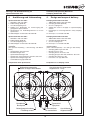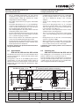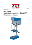
1
Montage- und Betriebsanleitung für
Spannstation NSL mini
Assembly and Operating Manual for
Clamping Station NSL mini
Spannstation
NSL mini
Clamping Station
NSL mini
04 / Spannstation NSL mini / de-en
Dokument-Stand: 2012-10-29
1
Montage- und Betriebsanleitung für
Spannstation NSL mini
Assembly and Operating Manual for
Clamping Station NSL mini
Sehr geehrter Kunde,
Dear Customer,
wir gratulieren zu Ihrer Entscheidung für SCHUNK.
Damit haben Sie sich für höchste Präzision, hervorragende Qualität und besten Service entschieden.
Congratulations on choosing a SCHUNK product.
By choosing SCHUNK, you have opted for the
highest precision, top quality and best service.
Sie erhöhen die Prozesssicherheit in Ihrer
Fertigung und erzielen beste Bearbeitungsergebnisse – für die Zufriedenheit Ihrer Kunden.
You are going to increase the process reliability
of your production and achieve best machining
results – to the customer's complete satisfaction.
SCHUNK-Produkte werden Sie begeistern.
Unsere ausführlichen Montage- und Betriebshinweise unterstützen Sie dabei.
SCHUNK products are inspiring.
Our detailed assembly and operation manual will
support you.
Sie haben Fragen? Wir sind auch nach Ihrem Kauf
jederzeit für Sie da. Sie erreichen uns unter den
unten aufgeführten Kontaktadressen.
Do you have further questions? You may contact us
at any time - even after purchase. You can reach us
directly at the below mentioned addresses.
Mit freundlichen Grüßen
Kindest Regards,
Ihre SCHUNK GmbH & Co. KG
Spann- und Greiftechnik
Your SCHUNK GmbH & Co. KG
Precision Workholding Systems
SCHUNK GmbH & Co. KG
Spann- und Greiftechnik
Bahnhofstr. 106-134
74348 Lauffen/Neckar
Deutschland
Tel. +49-7133-103-0
Fax +49-7133-103-2359
[email protected]
www.schunk.com
Reg. No. 003496 QM08
Reg. No. 003496 QM08
AUSTRIA: SCHUNK Intec GmbH
Tel. +43-7229-65770-0 · Fax +43-7229-65770-14
[email protected] · www.at.schunk.com
BELGIUM, LUXEMBOURG:
SCHUNK Intec N.V. / S. A.
Tel. +32-53-853504 · Fax +32-53-836351
[email protected] · www.be.schunk.com
CANADA: SCHUNK Intec Corp.
Tel. +1-905-712-2200 · Fax +1-905-712-2210
[email protected] · www.ca.schunk.com
CHINA: SCHUNK Intec
Precision Machinery Trading (Shanghai) Co., Ltd.
Tel. +86-21-51760266 · Fax +86-21-51760267
[email protected] · www.cn.schunk.com
CZECH REPUBLIC: SCHUNK Intec s.r.o.
Tel. +420-531-022066 · Fax +420-531-022065
[email protected] · www.cz.schunk.com
DENMARK: SCHUNK Intec A/S
Tel. +45-43601339 · Fax +45-43601492
[email protected] · www.dk.schunk.com
FINLAND: SCHUNK Intec Oy
Tel. +358-9-23-193861 · Fax +358-9-23-193862
[email protected] · www.fi.schunk.com
FRANCE: SCHUNK Intec SARL
Tel. +33-1-64663824 · Fax +33-1-64663823
[email protected] · www.fr.schunk.com
GREAT BRITAIN: SCHUNK Intec Ltd.
Tel. +44-1908-611127 · Fax +44-1908-615525
[email protected] · www.gb.schunk.com
HUNGARY: SCHUNK Intec Kft.
Tel. +36-46-50900-7 · Fax +36-46-50900-6
[email protected] · www.hu.schunk.com
INDIA: SCHUNK Intec India Private Ltd.
Tel. +91-80-40538999 · Fax +91-80-40538998
[email protected] · www.in.schunk.com
ITALY: SCHUNK Intec S.r.l.
Tel. +39-031-4951311 · Fax +39-031-4951301
[email protected] · www.it.schunk.com
JAPAN: SCHUNK Intec K.K.
Tel. +81-33-7743731 · Fax +81-33-7766500
[email protected] · www.tbk-hand.co.jp
MEXICO, VENEZUELA:
SCHUNK Intec S.A. de C.V.
Tel. +52-442-211-7800 · Fax +52-442-211-7829
[email protected] · www.mx.schunk.com
NETHERLANDS: SCHUNK Intec B.V.
Tel. +31-73-6441779 · Fax +31-73-6448025
[email protected] · www.nl.schunk.com
NORWAY: SCHUNK Intec AS
Tel. +47-210-33106 · Fax +47-210-33107
[email protected] · www.no.schunk.com
POLAND: SCHUNK Intec Sp.z o.o.
Tel. +48-22-7262500 · Fax +48-22-7262525
[email protected] · www.pl.schunk.com
2
RUSSIA: OOO SCHUNK Intec
Tel. +7-812-326 78 35 · Fax +7-812-326 78 38
[email protected] · www.ru.schunk.com
SLOVAKIA: SCHUNK Intec s.r.o.
Tel. +421-37-3260610 · Fax +421-37-6421906
[email protected] · www.sk.schunk.com
SOUTH KOREA: SCHUNK Intec Korea Ltd.
Tel. +82-31-7376141 · Fax +82-31-7376142
[email protected] · www.kr.schunk.com
SPAIN, PORTUGAL: SCHUNK Intec S.L.U.
Tel. +34-937 556 020 · Fax +34-937 908 692
[email protected] · www.es.schunk.com
SWEDEN: SCHUNK Intec AB
Tel. +46-8-554-42100 · Fax +46-8-554-42101
[email protected] · www.se.schunk.com
SWITZERLAND, LIECHTENSTEIN:
SCHUNK Intec AG
Tel. +41-523543131 · Fax +41-523543130
[email protected] · www.ch.schunk.com
TURKEY: SCHUNK Intec
Tel. +90-2163662111 · Fax +90-2163662277
[email protected] · www.tr.schunk.com
USA: SCHUNK Intec Inc.
Tel. +1-919-572-2705 · Fax +1-919-572-2818
[email protected] · www.us.schunk.com
Montage- und Betriebsanleitung für
Spannstation NSL mini
Assembly and Operating Manual for
Clamping Station NSL mini
Inhaltsverzeichnis / Table of Contents
Seite / Page
1.
2.
3.
Zu dieser Anleitung / About this manual
4
1.1
1.2
1.3
1.4
1.5
1.6
4
4
4
4
4
5
Zweck/Gültigkeit / Purpose/Validity
Zielgruppen / Target groups
Mitgeltende Unterlagen / Applicable documents
Symbole in dieser Anleitung / Symbols in this manual
Urheberrecht / Copyright
Technische Änderungen / Technical changes
Allgemeines / General
5
2.1
2.2
2.3
2.4
5
5
6
Gewährleistung / Warranty
Wichtige Hinweise / Important Notes
Dokumentation / Documentation
Hinweise auf nachweispflichtige Unterweisung des Bedienerpersonals
Notes on Instruction of Operating Personnel (for which proof is required)
6
Sicherheit / Safety
6
3.1
3.2
3.3
6
7
9
Bestimmungegemäßer Gebrauch / Proper use
Sicherheitshinweise / Safety information
Organisatorische Maßnahmen / Organisational Measures
4.
Ausführung und Lieferumfang / Design and scope of delivery
10
5.
Technische Daten / Technical data
11
6.
7.
Montage / Assembly
11
6.1 Allgemeine Montagehinweise / General assembly notes
6.2 Befestigung und Ausrichtung der Spannstation / Befestigung und Ausrichtung der Spannstation
6.2.1 NSL mini 100-2
6.2.2 NSL mini 100-3
6.2.3 Ausrichten und Anschraubstellen / Alignement and screw-on points
6.3 Anschlüsse der Spannstation / Design of the clamping station
6.3.1 Entriegelungsanschluss / Unlocking connection
6.3.2 Turboanschluss / Turbo connection
6.4 Verbinden mehrerer Spannstationen NSL mini 100-2 /
Connection of several NSL mini 100-2 clamping stations
6.5 Spannbolzen SPA mini 20, SPB mini 20, SPC mini 20 /
Clamping pins SPA mini 20, SPB mini 20, SPC mini 20
12
12
12
14
15
16
16
16
18
Wartung und Pflege / Maintenance and care
20
7.1
7.2
7.3
8.
9.
10.
Zerlegen und Zusammensetzen der Spannstation / Disassembly and assembly of the Clamping Station 20
Funktionsprüfung / Functionality test
21
Dichtheitsprüfung / Leak test
22
Problemanalyse / Trouble shooting
8.1
16
22
Notentriegelung bei Funktionsstörungen der Spannstation /
Emergency release in case of malfunctions of the clamping station
23
Dichtsatz- und Stücklisten / Seal kit and part lists
23
9.1
9.2
23
24
Dichtsatzlisten / Seal kit lists
Stücklisten / Part lists
Zusammenbauzeichnungen / Assembly drawings
3
25
Montage- und Betriebsanleitung für
Spannstation NSL mini
Assembly and Operating Manual for
Clamping Station NSL mini
1.
Zu dieser Anleitung
1.
About this manual
1.1
Zweck / Gültigkeit
1.1
Purpose / Validity
Diese Anleitung ist Teil der Spannstation NSL mini. Sie beschreibt den zuverlässigen und sachgemäßen Einsatz in
allen Betriebsphasen. Diese Anleitung ist ausschließlich für
die Spannstation NSL mini gültig.
This manual is part of the Clamping Station NSL mini. It
describes the reliably and proper use during all phases of
operation. This manual is valid only for the Clamping
Station NSL mini.
1.2
1.2
Zielgruppen
Target groups
§ Hersteller, Betreiber:
Diese Anleitung dem Personal jederzeit zugänglich halten. Personal zum Lesen und Beachten dieser Anleitung
und der mitgeltenden Unterlagen anhalten, insbesondere
der Sicherheitshinweise und Warnhinweise.
§ Manufacturer, Operator:
Keep this manual available for the personnel at all times.
Require personnel to read and observe this manual and
the applicable documents, especially the safety notes and
warnings.
1.3
1.3
§ Fachpersonal, Monteur:
Diese Anleitung und die mitgeltenden Unterlagen lesen,
beachten und befolgen, insbesondere die Sicherheitshinweise und Warnhinweise.
§ Skilled personnel, Fitter:
Read, observe and follow this manual and the applicable
documents, especially the safety notes and warnings.
Mitgeltende Unterlagen
§ Katalog
Technische Daten bzw. Einsatzparameter der Module und
Informationen zu Zubehörteilen. Es gilt jeweils die letzte
Fassung.
Applicable documents
§ Catalog
Technical data or application parameters of the module
and information on accessories. The last version is always
valid.
§ Montage- und Betriebsanleitung für Nullpunktspannmodule
Weiterführende Informationen zur Montage, Einstellung
und Instandsetzung der Nullpunktspannmodule.
§ Assembly and Operating Manuals for QuickChance Pallet Modules
Additional information relating to assembly, adjustment
and maintenance of the Quick-Change Pallet Module.
1.4
1.4
§ Allgemeine Geschäftsbedingungen (AGB)
U. a. Hinweise zur Gewährleistung.
WARNUNG
VORSICHT
HINWEIS
1.5
§ General terms of business
Including notes on the warranty.
Symbole in dieser Anleitung
Gefahren für Personen.
Nichtbeachtung kann zu Tod oder schweren Verletzungen führen.
WARNING
Gefahren für Personen.
Nichtbeachtung kann zu Verletzungen führen.
Beschädigungen des Systems sind möglich.
CAUTION
Informationen zur Vermeidung von Sachschäden,
zum Verständnis oder zum Optimieren der Arbeitsabläufe.
Urheberrecht
Symbols in this manual
Dangers for persons.
Nonobservance can cause death or serious injuries.
Dangers for persons.
Nonobservance can cause slight injuries.
Beschädigungen des Systems sind möglich.
NOTICE
Information on avoiding material damage, for
explanation or to optimize the work processes.
1.5
Copyright
Die vorliegende Betriebsanleitung sowie die Betriebsunterlagen bleiben urheberrechtlich Eigentum der SCHUNK
GmbH & Co. KG. Sie werden nur unseren Kunden und
den Betreibern unserer Produkte mitgeliefert und gehören
zur Spannstation.
The copyrights on the operating instructions and the operating documentation belong to SCHUNK GmbH & Co. KG.
Documentation is only delivered to our customers and
users of our products and forms part of the Clamping
Station.
Ohne unsere ausdrückliche Genehmigung dürfen diese
Unterlagen weder vervielfältigt noch dritten Personen,
insbesondere Wettbewerbsfirmen, zugänglich gemacht
werden.
This documentation may not be duplicated or made
accessible to third parties, in particular competitive companies, without our prior permission.
4
Montage- und Betriebsanleitung für
Spannstation NSL mini
1.6
Assembly and Operating Manual for
Clamping Station NSL mini
Technische Änderungen
1.6
Technical changes
Änderungen im Sinne technischer Verbesserungen sind
uns vorbehalten.
We reserve the right to make changes in the interest of
technical improvements.
2.
Allgemeines
2.
General
2.1
Gewährleistung
2.1
Warranty
Die Gewährleistung beträgt 12 Monate ab Lieferdatum
Werk bei bestimmungsgemäßem Gebrauch im 1-Schicht
Betrieb und unter Beachtung der vorgeschriebenen
Wartungs- und Schmierintervalle.
The warranty period is 12 months from the date of delivery when utilized as intended in single-shift operations
and in compliance with the specified maintenance and
lubrication intervals.
Grundsätzlich sind werkstücksberührende Teile und
Verschleißteile nicht Bestandteil der Gewährleistung.
Verschleißteile sind im Kapitel Dichtsatz- und Ersatzteilstücklisten als solche gekennzeichnet. Beachten Sie hierzu auch unsere Allgemeinen Geschäftsbedingungen
(AGB). Diese finden Sie auf unserer Webseite
www.de.schunk.com unter »Service« bei den »Verkaufsund Lieferbedingungen«.
Parts that come into contact with the workpiece and wearing parts are not covered by the warranty. Wearing parts
are designated accordingly in the Seal kit and spare parts
lists.
See also our General Terms and Conditions in this regard.
The unit is considered as damaged, if its basic function
“clamping of clamping pallets” is not given any more.
Die Einheit gilt dann als defekt, wenn deren Grundfunktion
Spannen von Spannpaletten nicht mehr gegeben ist.
2.2
Wichtige Hinweise
2.2
Important Notes
Unabhängig von den in dieser Betriebsanleitung aufgeführten Hinweisen gelten die gesetzlichen »Sicherheitsund Unfallverhütungsvorschriften« sowie die »EG-Maschinenrichtlinie«. Jede Person, die vom Betreiber mit der
Bedienung, Wartung und Instandsetzung der Spannstation beauftragt ist, muss vor Inbetriebnahme die Betriebsanleitung, insbesondere das Kapitel 3 »Sicherheit«
gelesen und verstanden haben. Genaue Erläuterungen
sind im Kapitel 2.4 »Hinweise auf nachweispflichtige
Unterweisung des Bedienerpersonals« zu finden.
The instructions set out in this manual do not affect the
“Safety Rules and Regulations” laid down in law and the
E.E.C. machine recommendation. Anyone being in charge
of the operation, maintenance and repair of the Clamping
Station appointed by the business operator, must have
read and understood the operating instructions in particular chapter 3 “Safety” before the chuck is set into operation. Exact explanations can be found under “Notes on
instruction of the operating personnel, proof for which is
required” in chapter 2.4.
Instandsetzer der Spannstation sind für die Arbeitssicherheit grundsätzlich selbst verantwortlich.
It is the duty of the personnel carrying out repairs to the
Clamping Station to ensure work safety.
Die Beachtung aller geltenden Sicherheitsvorschriften
und gesetzlichen Auflagen ist Voraussetzung, um Schäden an Personen und dem Produkt bei Wartung sowie
Reparaturarbeiten zu vermeiden. Instandsetzer müssen
diese Vorschriften vor Beginn der Arbeiten gelesen und
verstanden haben.
It is essential to observe the current safety regulations and
legal prerequisites to avoid damage to persons and to the
product during maintenance and repair work. Before carrying out repairs, personnel must have read and understood these instructions.
Proper repair work to SCHUNK products can only be carried out by personnel that has been trained accordingly. It
is the responsibility of the operating business and the
repair personnel to ensure that appropriate training is
received. It is their duty to see that operators and future
repair personnel receive adequate product training by
experts.
Die sachgemäße Instandsetzung der SCHUNK-Produkte
setzt entsprechend geschultes Fachpersonal voraus. Die
Pflicht der Schulung obliegt dem Betreiber bzw. Instandsetzer. Dieser hat Sorge dafür zu tragen, dass die
Bediener und zukünftigen Instandsetzer für das Produkt
fachgerecht geschult werden.
Der Gewährleistungsanspruch erlischt, wenn Schäden
durch unsachgemäße Bedienung entstehen. Zum Erlöschen jeglichen Gewährleistungsanspruches führen Reparaturarbeiten oder Eingriffe, die von hierzu nicht ermächtigten Personen vorgenommen werden, und die Verwendung von Zubehör und Ersatzteilen, auf die unsere
Spannstation nicht abgestimmt ist.
The warranty does not cover damage occurring as a result
of inexpert operation. Repair or intervention carried out by
persons not authorised to do so will result in the exclusion
of all claims under warranty. The same applies if accessories and spare parts are used which are not designed
for our Clamping Station.
5
Montage- und Betriebsanleitung für
Spannstation NSL mini
Assembly and Operating Manual for
Clamping Station NSL mini
Pannen sofort nach Erkennen melden. Defekte unverzüglich instandsetzen, um den Schadensumfang gering
zu halten und die Sicherheit der Spannstation nicht zu
beeinträchtigen. Bei Nichteinhaltung entfällt der weitere
Gewährleistungsanspruch.
Malfunctions must be reported immediately after they are
detected. Defects must be remedied without delay in order
to limit the extent of damage and to avoid compromising
the safety of the Clamping Station. Failure to comply with
this instruction will void the warranty.
Wir weisen darauf hin, dass wir für Schäden,
die sich durch Nichtbeachtung dieser Betriebsanleitung ergeben, keine Haftung übernehmen.
Please note that we cannot accept any liability
for damage caused by not observing this
Operating Manual.
HINWEIS
2.3
NOTICE
Dokumentation
2.3
Documentation
Zum Lieferumfang der Spannstation, die von der
SCHUNK GmbH & Co. KG konstruiert und gebaut wird,
gehört eine gerätebezogene Dokumentation.
A product specific documentation is supplied as part of the
scope of delivery of the Clamping Station, designed and
manufactured by SCHUNK GmbH & Co. KG.
Die Zuordnung des entsprechenden Dokumentationsteiles zur richtigen Zielgruppe obliegt dem Anwender. Er
hat dafür Sorge zu tragen, dass zumindest ein Exemplar
der Dokumentation in unmittelbarer Nähe der Maschine,
an der die Spannstation angebaut ist, aufbewahrt wird und
der betroffenen Zielgruppe zugänglich ist.
It is the responsibility of the user to provide the relevant
persons with access to the appropriate documentation. It
is his duty to ensure that at least one copy of the documentation is kept close to the machine on which the
Clamping Station is mounted and that it is accessible to
the relevant persons.
Jede Person, die mit Tätigkeiten an der Spannstation
beauftragt ist, muss vor Arbeitsaufnahme die entsprechende Dokumentation gelesen und sich insbesondere
mit dem Kapitel »Sicherheit« vertraut gemacht haben.
Every person being in charge with tasks of the Clamping
Station must have read the relevant documentation before
setting to work and in particular being familiar himself with
the chapter dealing with “Safety”.
Dies gilt insbesondere für Personal, das nur gelegentlich
mit Arbeiten an der Spannstation betraut ist, z.B.
Wartungspersonal.
This is particularly valid for personnel only in charge of
work on the Clamping Station occasionally, e.g. maintenance personnel.
2.4
2.4
Hinweise auf nachweispflichtige
Unterweisung des Bedienerpersonals
Notes on Instruction of Operating Personnel (for which proof is required)
Wir empfehlen dem Betreiber unserer Spannstation alle
Personen die mit der Bedienung, Wartung und Instandsetzung derselben beauftragt sind, die Betriebsanleitung,
insbesondere das Kapitel »Sicherheit«, zum Erwerb der
Fachkenntnisse zur Verfügung zu stellen. Desweiteren
empfehlen wir innerbetriebliche »Betriebsanweisungen«,
unter Berücksichtigung der ihm bekannten Qualifikation
des jeweils eingesetzten Personals, zu erstellen.
We recommend that the business operating our Clamping
Station makes the operating instructions in particular the
section “Safety” available to all persons being in charge of
operation, maintenance and repair, with the intention of
acquiring specialised knowledge. We further recommend
that the business operator issues internal “operating
instructions” which take into account the known qualifications of the operating personnel.
Die Teilnahme an Einweisungen, Schulungen, Lehrgängen
usw., die der Kenntnisgewinnung bei der Bedienung, Wartung und Instandsetzung der Spannstation dienen, sollte
dem Betreiber schriftlich bestätigt werden. Dazu empfehlen
wir die in der Anlage beigefügte Kenntniserklärung zu verwenden.
Participation in information sessions, training programmes
and courses etc. with the aim of gaining knowledge in
operation, maintenance and repair of the Clamping
Station should be confirmed in writing to the business
operator. For this purpose please use the enclosed
“Declaration of Knowledge”.
3.
Sicherheit
3.
Safety
3.1
Bestimmungsgemäßer Gebrauch
3.1
Proper use
Die Spannstation wurde konstruiert zum Spannen von
Spannpaletten, Spannvorrichtungen oder Werkstücken.
The Clamping Station is designed for clamping of clamping pallets, clamping devices or workpieces.
Das Produkt ist zum Ein-/Anbau für Maschinen bzw.
Anlagen bestimmt. Die Anforderungen der zutreffenden
Richtlinien müssen beachtet und eingehalten werden.
This product is intended for installation / mounting for
machinery and equipment. The requirements of the applicable directives must be observed and complied with.
6
Montage- und Betriebsanleitung für
Spannstation NSL mini
Assembly and Operating Manual for
Clamping Station NSL mini
Das Produkt darf ausschließlich im Rahmen seiner technischen Daten verwendet werden.
This product may only ever be employed within the restrictions of its technical specifications.
Ein darüberhinausgehender Gebrauch gilt als nicht
bestimmungsgemäß. Für Schäden aus einem solchen
Gebrauch haftet der Hersteller nicht.
Using the system with disregard to even a minor specification will be deemed inappropriate use. The manufacturer assumes no liability for any injury or damage resulting
from inappropriate use.
Verwendungszweck
Die Spannstation dient dem zwischen Hersteller/ Lieferer
und Anwender vertraglich vereinbarten Verwendungszweck sowie demjenigen Verwendungszweck, der sich
aus der Produktbeschreibung und dem Gebrauch im
Rahmen der technischen Werte entspricht.
Case of application
The Clamping Station is to be used for the case of application contractually agreed between the producer/deliverer and the user, as well as such cases of application described in the product description which are also
in accordance with the technical values.
Die Betriebssicherheit ist bei bestimmungsgemäßer Verwendung unter Beachtung der einschlägigen Sicherheitsbestimmungen, soweit als vorhersehbar, gewährleistet.
The safe function is as far as it can be foreseen, guaranteed when it is used for the intended purpose in accordance with the appropriate safety regulations.
Bei unsachgemäßem Gebrauch der Spannstations können
– Gefahren für Leib und Leben des Bedieners,
Improper use of the Clamping Station can result in
– Danger to life and limb of the operator,
–
–
Gefahren für die Spannstation und weiterer Vermögenswerte des Betreibers oder Dritter, entstehen.
3.2
–
–
Sicherheitshinweise
Danger to the Clamping Station and to further
assets of either the business operator or a third
party.
3.2
Die Spannstation ist nach dem Stand der Technik zum
Zeitpunkt der Auslieferung gebaut. Gefahren können
von ihm jedoch ausgehen, wenn z.B.:
–
Safety information
The Clamping Station is built according to the level of
technology available at the time of delivery. However,
the system may still be dangerous if, for example:
die Spannstation unsachgemäß eingesetzt, montiert,
gewartet oder zum nicht bestimmungsgemäßen
Gebrauch eingesetzt wird.
the Clamping Station is used, assembled or maintained inappropriately or is used for purposes other
than those it is intended for.
die EG-Maschinenrichtlinie, die UVV, die VDE-Richtlinien, die Sicherheits- und Montagehinweise nicht
beachtet werden.
the EC Machine Directive, the accident prevention regulations, the VDE guidelines, or the safety information
and assembly instructions are not heeded.
Der Ein- und Ausbau, das Anschließen und die
Inbetriebnahme darf nur von autorisiertem Personal
durchgeführt werden.
WARNUNG
–
The installation, deinstallation, connection and commissioning may only be performed by authorized,
appropriately trained personnel.
WARNUNG
WARNING
Die Spannstation darf nicht für den Einsatz
unter dynamischer Bearbeitung auf Fräsmaschinen mit angetriebenem Maschinentisch
eingesetzt werden.
It is not allowed to use the Clamping Station for
dynamic machining on milling machines with a
driven machine table.
WARNING
WARNING
WARNUNG
WARNUNG
WARNUNG
Bei horizontaler Lage der Spannbolzenachse
oder bei Überkopfanwendungen ist vor dem
Lösen sicherzustellen, dass die Vorrichtung
oder Palette gegen Herunterfallen gesichert ist.
WARNING
WARNUNG
WARNING
Beim Ankuppeln der Luftversorgung am Eingang »Öffnen« kann sich die gekoppelte
Spannpalette von der Spannstation lösen, oder
das Werkstück aus dem Spannmittel herausfallen.
During connection of the air supply at the input
"Opening", the coupled clamping pallet may
loosen from the clamping station, or the workpiece may fall out of the clamping device.
WARNING
CAUTION
VORSICHT
VORSICHT
If the axis of the clamping pins should be horizontally positioned, or in case of overhead
applications, make sure that the device or pallet is secured against falling down, before you
are loosening them.
Beim Be- und Entladen darf generell nur ein
Bediener an der Spannstation arbeiten.
CAUTION
7
During loading and unloading generally just
one operator should work at the clamping
station.
Montage- und Betriebsanleitung für
Spannstation NSL mini
VORSICHT
Assembly and Operating Manual for
Clamping Station NSL mini
VORSICHT
CAUTION
Während des Betriebes ist ein irrtümliches oder
fahrlässiges Lösen des Spannbolzens durch
geeignete Gegenmaßnahmen (Abkoppeln der
Energiezufuhr nach der Verriegelung, Verwendung von Sicherheitsventilen oder -schaltern)
auszuschließen.
An erroneous or negligent loosening of the
clamping pins during operation is to be excluded through suitable countermeasures (disconnection of energy supply after locking, application of safety valves or switches).
CAUTION
CAUTION
VORSICHT
VORSICHT
VORSICHT
HINWEIS
HINWEIS
HINWEIS
HINWEIS
HINWEIS
HINWEIS
Nicht in die offene Mechanik der Spannbolzenaufnahme greifen. Beim Ankoppeln der Luftversorgung nicht in die beweglichen Teile oder
Spannmittel der Spannstation hineingreifen.
CAUTION
VORSICHT
CAUTION
Bei der Montage, beim Anschließen, Einstellen,
Inbetriebnehmen und Testen muss sichergestellt sein, dass ein versehentliches Betätigen
der Spannstation durch den Monteur oder
andere Personen ausgeschlossen ist.
During assembly, connection, setting, commissioning and testing, it is important to eliminate
the possibility of the fitter or any other persons
accidentally activating the Clamping Station.
CAUTION
Arbeitsweisen, die die Funktion und Betriebssicherheit der Spannstation beeinträchtigen, sind zu
unterlassen.
NOTICE
Bei Montage-, Umbau-, Wartungs- und Einstellarbeiten die Energiezuführungen entfernen. Wartungsarbeiten, Umbauten oder Anbauten außerhalb der Gefahrenzone durchführen.
Die Haltekraft der Spannstation wird im wesentlichen von der Festigkeit der Schraubenverbindungen begrenzt, mit der die Spannbolzen mit
der Palette bzw. Vorrichtung verbunden sind. Deshalb dürfen nur Schrauben der Festigkeitsklasse
12.9 verwendet werden.
–
Modes of operation that adversely affect the function and/ or the operational safety of the gripper are
to be refrained from.
NOTICE
Always disconnect the power supply lines during
assembly, conversion, maintenance and setting
work. Always carry out maintenance work, conversions and attachments outside of the danger zone.
NOTICE
The holding force of the Clamping Station is essentially limited by the strength of the screwed connections with which the clamping pins are connected
to the pallet or device. Therefore fastening screws
of the property class 12.9 are to be used only.
NOTICE
Es dürfen nur Original SCHUNK-Spannbolzen verwendet werden.
Bei der Verwendung des Spannbolzens in kundeneigenen Vorrichtungen ist eine ausreichend dimensionierte Gewindebohrung bzw. eine ausreichende
Materialstärke durch den Kunden vorzusehen.
NOTICE
Veränderungen und Nacharbeiten (zusätzliche
Gewinde, Bohrungen, Überschleifen) oder Anbauten, die nicht als Zubehör von SCHUNK angeboten
werden, dürfen nur mit Genehmigung der Fa.
SCHUNK angebracht werden.
NOTICE
Only original
SCHUNK-Clamping-Pins are to be used.
When the clamping pin is used in the customer’s
own assembly device, the customer is to provide
for a sufficiently dimensioned tap and satisfactory
strength of the material.
Alterations and modifications (additional threads,
holes, grinding) or attachments which are not supplied as accessories by SCHUNK may only be
applied after obtaining the prior consent of
SCHUNK.
This also applies to the installation of safety
devices.
Dies gilt auch für den Einbau von Sicherheitseinrichtungen.
–
Do not touch any open mechanics in the
mounting area of the clamping pin. Do not
touch the moving parts or the clamping device
of the clamping station during the connection
of the air supply.
Die Wartungs- und Pflegeintervalle sind einzuhalten.
Die Intervalle beziehen sich auf eine normale Umgebung. Soll die Spannstation in einer Umgebung mit
abrasiven Stäuben oder ätzenden bzw. aggressiven
Dämpfen bzw. Flüssigkeiten betrieben werden, so ist
vorher die Genehmigung der Fa. SCHUNK einzuholen.
Darüber hinaus gelten die am Einsatzort gültigen
Sicherheits- und Unfallverhütungsvorschriften.
8
–
The maintenance and servicing intervals must always
be complied with. The intervals indicated refer to a
standard working environment. Operating the gripper
in an environment in which it is subjected to abrasive
dusts or corrosive and/or aggressive vapours and/or
liquids requires the prior consent of SCHUNK.
–
Above and beyond that, the safety and accident prevention regulations in force at the location of use
apply.
Montage- und Betriebsanleitung für
Spannstation NSL mini
3.3
Assembly and Operating Manual for
Clamping Station NSL mini
Organisatorische Maßnahmen
3.3
Einhaltung der Vorschriften
Der Betreiber hat durch geeignete Organisations- und Instruktionsmaßnahmen sicherzustellen, dass die einschlägigen Sicherheitsvorschriften und Sicherheitsregeln von
den Personen, die mit der Bedienung, Wartung und Instandsetzung der Spannstation betraut sind, beachtet
werden.
Organisational Measures
Compliance with the Regulations
The business operator must guarantee that suitable
measures in organisation and instruction are taken to
ensure that the appropriate safety rules and regulations
are complied with by the persons entrusted with operation,
maintenance and repair of the Clamping Station.
Supervision of Conduct
The business operator is required, at least from time to
time, to check personnel’s conduct regarding awareness
of safety and hazards.
Kontrolle des Verhaltens
Der Betreiber hat zumindest gelegentlich das sicherheitsund gefahrenbewusste Verhalten des Personals zu kontrollieren.
Hazard Notices
The business operator must ensure that the notes of safety and hazards for the machine to which the Clamping
Station is mounted are observed and that the notice signs
are clearly legible.
Gefahrenhinweise
Der Betreiber hat darauf zu achten, dass die Sicherheitsund Gefahrenhinweise an der Maschine, an der die
Spannstation angebaut ist, beachtet werden und dass die
Hinweisschilder in gut lesbarem Zustand sind.
Störungen
Treten an der Spannstation sicherheitsrelevante Störungen auf, oder lässt das Produktionsverhalten auf solche schließen, ist die Maschine, an der die Spannstation
angebracht ist, sofort stillzusetzen und zwar so lange, bis
die Störung gefunden und beseitigt ist.
Störungen nur durch ausgebildetes und autorisiertes
Personal beheben lassen.
Troubles
If troubles occur at the Clamping Station which could
affect safety or production characteristics indicate that
faults are in existence, the machine (to which the
Clamping Station is mounted) must be stopped immediately and stand still as long as required to locate and eliminate the fault.
Troubles may be eliminated by trained and authorised
personnel only.
Ersatzteile
Nur Ersatzteile verwenden, die den vom Hersteller bzw.
Lieferer festgelegten Anforderungen entsprechen. Dies ist
bei Originalersatzteilen immer gewährleistet.
Spare Parts
Only use spare parts which meet the requirements of the
manufacturer and/or the supplier. This is always guaranteed if original spare parts are used.
Unsachgemäße Reparaturen, sowie falsche Ersatzteile
führen zum Ausschluss der Produkthaftung/Gewährleistung.
Improper repair as well as use of wrong spare parts
results in the exclusion from product liability/warranty.
Choice of Personnel, Personnel qualifications
– Work at the Clamping Station may only be carried out
by reliable personnel, whereby the legal minimum age
must be considered.
Personalauswahl, Personalqualifikation
– Arbeiten an der Spannstation dürfen nur von zuverlässigem Personal durchgeführt werden, hierbei ist das
gesetzliche Mindestalter zu beachten.
–
An der Spannstation nur geschultes und entsprechend
eingewiesenes Personal einsetzen, ggf. Schulungsangebote des Herstellers nutzen.
–
Zuständigkeitsbereiche des Personals für das Bedienen, Warten, Instandsetzen klar und eindeutig festlegen.
–
Wartungs- und Instandsetzungsarbeiten im sicherheitsrelevanten Bereich der Spannstation nur von Personal durchführen lassen, das im Sinne der Sicherheitsvorschriften als Sachkundiger gelten kann.
–
Bedienerverantwortung, auch im Hinblick auf sicherheitsgerechtes Verhalten festlegen, ihm die Ablehnung sicherheitswidriger Anweisungen durch Dritte
ermöglichen.
–
Personal, das sich in der Schulungs-, Einweisungs-,
Ausbildungs- oder Einlernphase befindet, nur unter
ständiger Aufsicht einer erfahrenen Person an der
Spannstation arbeiten lassen.
9
–
Only employ personnel who has been trained and
shown how to operate the Clamping Station and if necessary, make use of the manufacturer’s training programmes.
–
Clearly define the sphere of responsibility for personnel for operation, maintenance and repair.
–
Only allow personnel who is familiar with the safety
requirements of the Clamping Station to carry out
maintenance and repair work in the spheres (of the
Clamping Station) which are relevant to safety.
–
Also determine an operator who is responsible for
safety conscious conduct. Enable him to refuse
instructions by third parties who/which are irresponsible with regard to safety.
–
During training- and instruction period, the personnel
must be supervised by an experienced person on the
Clamping Station.
Montage- und Betriebsanleitung für
Spannstation NSL mini
4.
Assembly and Operating Manual for
Clamping Station NSL mini
Ausführung und Lieferumfang
4.
Design and scope of delivery
Spannstation NSL mini 100-2
Clamping Station NSL mini 100-2
–
4
1
2
BEIPACK: NSL mini 100-2
Bridenrohlinge (BRR 40)
Verschlusskupplung G 1/8"
Adapter incl. Dichtringen zur Luftversorgung bei
gekoppelten Spannstationen
2 Abstecklehren als Verbindungselement zur 4-fach
Spannstation
12 Abdeckkappen für Schraube ISO 4762 M6
–
4
1
2
Spannstation NSL mini 100-3
Clamping Station NSL mini 100-3
–
4
1
12
–
4
1
12
ENCLOSED PACK: NSL mini 100-2
Clamping pin blank (BRR 40)
Closure coupling G 1/8"
Adapter incl. seals for air supply on coupled clamping
stations
2 Plug gauges as connecting element to 4-way clamping
station
12 End caps for screw ISO 4762 M6
BEIPACK: NSL mini 100-3
Bridenrohlinge (BRR 40)
Verschlusskupplung G 1/8"
Abdeckkappen für Schraube ISO 4762 M6
ZUBEHÖR:
(bei separater Bestellung – siehe Katalog oder Datenblätter)
–
–
–
–
–
–
ACCESSORIES:
(when ordered separately – see catalog or data sheets)
–
–
–
–
–
–
Spannpaletten Type PAL mini
Modulerhöhungen mini
Spannmittelerhöhungen mini
Spannbolzen Typen SPA mini, SPB mini, SPC mini
Spannbolzenverlängerungen mini
Schutzabdeckung Type SDE mini
Komponenten einer Spannstation
Clamping pallets Type PAL mini
Module increases, mini
Clamping devices increases, mini
Clamping pin types SPA mini, SPB mini, SPC mini
Clamping pin extensions, mini
Protective cover type SDE mini
Components of a clamping station
Nullpunktspannmodule
Quick-Change Pallet Module
Ausrichtnuten für Nutensteine
Alignment for T-nuts
Grundplatte
Base plate
Befestigungsschrauben
Fastening screws
ENCLOSED PACK: NSL mini 100-3
Clamping pin blank (BRR 40)
Closure coupling G 1/8"
End caps for screw ISO 4762 M6
Typenschild
Type plate
Luftanschlüsse
Air connections
10
Ausrichtkante
Alignment edge
Montage- und Betriebsanleitung für
Spannstation NSL mini
Assembly and Operating Manual for
Clamping Station NSL mini
Unterschiedliche Ausführungen
Different Designs
Ausrichtkante
Alignment edge
Lineare Anordnung der Nullpunktspannmodule
Linear arrangement of the quick change clamping modules
5.
Radiale Anordnung der Nullpunktspannmodule
Radial arrangement of the quick change clamping modules
Technische Daten
Technical data
Haltekraft
(M6 / M8) *
Retenion force
(M6 / M8) *
Einzugskraf
ohne Turbo
Pull-down force
without turbo
Einzugskraft
mit Turbo
Pull-down force
with turbo
Betätigungsdruck
Operating
pressure
Wiederholgenauigkeit
Repeatability
Gewicht
Weight
0435220
15 / 25 kN
0.5 kN
1.2 kN
6 bar
< 0.005 mm
3.4 kg
0435230
15 / 25 kN
0.5 kN
1.2 kN
6 bar
< 0.005 mm
6.0 kg
Bezeichnung Ident-Nr.
Description
Id.-No.
NSL mini
100-2
NSL mini
100-3
5.
* Haltekraft bei Befestigung des Spannbolzens mit
Zylinderschraube – DIN EN ISO 4762/12.9
* Retention force mounting the clamping pin with
cylindrical head screw – DIN EN ISO 4762/12.9
Betriebstemperatur:
15° – 60°C
Operating temperature:
15° – 60°C
Einbaulage:
beliebig
Installation position:
variable
Druckmittel
Druckluft
Pressure medium
Druckluft
Mindestdruck
5 bar
– Der Betriebsdruck sollte 5 bar nicht unterschreiten
Minimum pressure
5 bar
– The operating pressure should not drop below 5 bar
Betätigungsdruck
6 bar
Operating pressure
6 bar
10 bar
Maximum pressure
10 bar
Maximaldruck
Anforderung an die Druckluftqualität nach ISO 8573-1:
6 4 4 (gefiltert (10 µm), trocken und geölt).
Standard for quality of the compressed air according to ISO
8573-1: 6 4 4 (filtered (10 microns), dry and lubricated).
Die Luftversorgung muss über eine separate Wartungseinheit mit Öler erfolgen.
The air supply must be done via a separate maintenance unit with oiler.
Weitere technische Angaben können dem aktuellen
Katalog und den Betriebsanleitung der eingesetzten
Module (mitgeltende Unterlagen) entnommen werden.
For further technical details see our current catalog
and the operating manual of the used modules
(applicable documents).
6.
6.
The airborne noise emitted by the System is ≤ 70 dB (A).
Der vom System ausgehende Luftschall ist ≤ 70 dB (A).
Montage
Assembly
Zum Transport der Spannstation eignen sich die als Zubehör erhältlichen Nullpunkt-Spannbolzen.
For transport of the clamping station, we recommend the
quick change clamping pins available as accessories.
In das Innengewinde der Spannbolzen lassen sich Ringschrauben einschrauben.
Eye bolts can be screwed into the inner threads of the
clamping pins.
Die Nullpunktspannmodule der Spannstation werden mit
Druckluft entriegelt um die Spannbolzen einzusetzen.
The quick change clamping modules of the clamping station are released with compressed air for insertion of the
clamping pins.
11
Montage- und Betriebsanleitung für
Spannstation NSL mini
HINWEIS
HINWEIS
6.1
Assembly and Operating Manual for
Clamping Station NSL mini
Zum Transport muss die Luftversorgung abgekoppelt sein, damit die Spannbolzen bleiben.
NOTICE
Bei der Montage des Spannstations muss die
Energieversorgung abgeschaltet sein. Die Sicherheitshinweise in Kapitel 3.2 beachten.
NOTICE
Allgemeine Montagehinweise
6.1
Zum Transport muss die Luftversorgung abgekoppelt sein, damit die Spannbolzen bleiben.
Always use the supplied eye bolts and insert them
in the provided bores of the base plates for transporting the clamping station.
General assembly notes
Beim Anschließen der Nullpunktspannsysteme berücksichtigen, dass eine vollständige Entlüftung des Kolbenraumes beim Verriegelungsvorgang möglich ist. Daher
entsprechende Ventile, Schalldämpfer oder Absperrhähne mit Entlastung vorsehen. Dies gilt auch für den
Turboanschluss. Wird der Turboanschluss nicht benutzt
muss sich die betreffende Kolbenseite entlüften können.
When connecting the Quick-Change Pallet Systems,
please make sure that complete deaeration of the piston
area during the locking operation is possible. Therefore,
valves, sound absorbers or stop valves for deaeration
should be available. The same applies for the turbo connection. If the turbo connection will not be used, it must be
possible that the relevant piston side can be deaerated.
Beim Abkoppeln von Schlauchleitungen müssen die entsprechenden Öffnungen mit Verschluss-Stopfen vor dem
Eindringen von Schmutz oder Kühlschmierstoff gesichert
werden.
When uncoupling the air hoses the corresponding openings have to be sealed with sealing plugs in order to prevent ingress of dirt or coolant into the module.
6.2
6.2
HINWEIS
Befestigung und Ausrichtung der
Spannstation
HINWEIS
Die Höhengleichheit der Module ist erst nach der
sachgemäßen Befestigung der Spannstation auf
dem Maschinentisch gegeben.
NOTICE
Fastening and alignment of the
clamping station
NOTICE
An equal height of the modules is not achieved
before the clamping station has been properly
fastened on the machine table.
6.2.1 NSL mini 100-2
6.2.1 NSL mini 100-2
(Pos.-Nr. siehe Zusammenbauzeichnungen, Kapitel 10)
(Item Nos. see assembly drawings, chapter 10)
Die Ausrichtung der Spannstation auf dem Maschinentisch erfolgt über Ausrichtkanten (siehe Abbildungen in
Kapitel 4). Durch Abtasten der Ausrichtkante über eine
bestimmte Weglänge lässt sich die Spannstation parallel
zum Maschinentisch ausrichten.
The clamping station is aligned on the machine table by
means of alignment edges (see illustrations in Chapter 4).
The clamping station can be aligned parallel to the
machine table by tracing the alignment edge over a particular length.
Die Spannstation NSL mini 100-2 bietet unterschiedliche
Möglichkeiten zur Befestigung auf dem Maschinentisch
Siehe Abbildung Seite 13).
The NSL mini 100-2 clamping station features various
options for mounting on the machine table (see illustration
on page 13).
Über die Einstellscheiben (Pos. 3), die sich unterhalb der
Spannmodule befinden kann ein flexibler Abstand zur
Befestigung der Spannstation gewählt werden. Die
Einstellscheiben werden passend positioniert und mit den
Schrauben (Pos. 8) arretiert und geklemmt. Die Befestigung der Spannstation an den Verschraubungsstellen
unterhalb der Spannmodule erfordert die Verwendung
von Zylinderschrauben nach ISO 7984 mit der Festigkeitsklasse 10.9. Sie sollten von oben zugänglich sein. Für die
erforderlichen Schraubenanzugsmomente siehe Tabelle
auf Seite 14. Beim Festziehen der Befestigungsschrauben einen Drehmomentschlüssel verwenden um Beschädigungen zu vermeiden.
The adjustment screws (no. 3) beneath the clamping modules allow flexibility in selecting the spacing for mounting
of the clamping station. Position the adjustment disks as
needed and fasten with screws (no. 8). Mounting of the
clamping station at the screw points beneath the clamping
modules requires the use of cylindrical screws with a
property class of 10.9 in accordance with ISO 7984. They
should be accessible from above. For the required tightening torques see the table on page 14. When tightening the
mounting screws, use a torque wrench to prevent damage
to the screws.
An offset screw pattern to the clamping modules by
means of the rotating adjustment disks requires that the
clamping modules first be removed. Removal of the
clamping modules is necessary for example if the clamping station is to be installed on machine tables with T-nut
spacings of 63 mm, 80 mm or 126 mm. Once the clamp-
Eine zu den Spannmodulen versetze Verschraubung über
die drehbaren Einstellscheiben erfordert die vorherige Demontage der Spannmodule. Die Demontage der Spannmodule ist beispielsweise erforderlich sobald die Spann-
12
Montage- und Betriebsanleitung für
Spannstation NSL mini
Assembly and Operating Manual for
Clamping Station NSL mini
ing modules of the clamping station are removed the
required screw spacing can be adjusted. Align the clamping station on the machine table and tighten the screws to
the permissible torque. Afterwards, you can again mount
the quick change clamping modules (no. 6) and the corresponding bottom-side sealing rings (no. 12). After mounting the clamping modules and the sealing rings, cover the
screw heads of the mounting screws with new plastic end
caps (included in scope of delivery).
station auf Maschinentischen mit T-Nutenabstände von
63 mm, 80 mm oder 126 mm verbaut werden soll. Sind die
Spannmodule von der Spannstation demontiert lässt sich
der erforderliche Verschraubungsabstand einstellen. Die
Spannstation wird auf dem Maschinentisch ausgerichtet
und mit dem zulässigen Schraubendrehmoment befestigt.
Anschließend können die Nullpunktspannmodule (Pos. 6)
und die dazugehörigen bodenseitigen Dichtringe (Pos.
12) erneut montiert werden. Nach erneuter Montage der
Spannmodule und der Dichtringe die Schraubenköpfe der
Befestigungsschrauben mit neuen Verschlusskappen aus
Kunststoff verschließen (liegen dem Lieferumfang bei).
Prior to mounting the quick change clamping modules,
clean the receiving bores of the base plate (no. 1) and
check all components for damage. Damaged sealing rings
must be replaced.
Vor der Montage der Nullpunktspannmodule die Aufnahmebohrungen der Grundplatte (Pos. 1) reinigen und
alle Komponenten auf Beschädigung kontrollieren. Beschädigte Dichtringe müssen ersetzt werden.
The NSL mini 100-2 clamping station can alternatively be
mounted on the corners of the base plate by means of the
BRR 40 blank mounting rings included in the scope of
delivery (see illustration in Chapter 6.2.3). The BRR 40
mounting rings should be screwed on using cylindrical
screws with a property class of 10.9 in accordance with
DIN ISO 4762. A through-hole for a mounting screw can
be drilled in the blank mounting rings by the customer.
To increase the clamping pressure, the mounting hole
should be positioned close to the inner protrusion.
Die Spannstation NSL mini 100-2 kann alternativ auch
über die in der Lieferung enthaltenen vier Bridenrohlinge
BRR 40 an den Ecken der Grundplatte befestigt werden
(siehe Abbildung in Kapitel 6.2.3). Die Briedenrohlinge
BRR 40 sollten mit Zylinderschrauben nach DIN ISO 4762
mit der Festigkeitsklasse 10.9 verschraubt werden. In den
Bridenrohlingen kann eine Kundenseitige Durchgangsbohrung für eine Befestigungsschraube gebohrt werden.
Um den Spanndruck zu erhöhen sollte die Anschraubbohrung nahe zur innenliegenden Ausbuchtung positioniert werden.
Aufbauvarianten auf verschiedenen Maschinentischen
Mounting variants on different machine tables
Abstand Tischnuten: 50 / 100 mm
Spacing of table slots: 50 / 100 mm
Abstand Tischnuten: 80 mm
Spacing of table slots: 80 mm
Abstand Tischnuten: 63 mm
Spacing of table slots: 63 mm
13
Montage- und Betriebsanleitung für
Spannstation NSL mini
Assembly and Operating Manual for
Clamping Station NSL mini
6.2.2 NSL mini 100-3
6.2.2 NSL mini 100-3
Die Ausrichtung der Spannstation auf dem Maschinentisch erfolgt über Nuten zur Aufnahme von Nutensteinen.
Zur Mittenausrichtung der Spannstation ist eine Zentrumsbohrung zur Aufnahme eines Ausrichtbolzens vorhanden.
The clamping station is aligned on the machine table by
means of slots for holding T-nuts. For central alignment of
the clamping station there is a center bore hole for receiving an alignment pin.
The NSL mini 100-3 clamping station features various
options for mounting on the machine table. In general, the
system is designed for mounting table tops with starshaped slots. A screw pattern can be selected at three or
four fixed-position screw points. The screw head countersinks for the mounting screws are located in the center of
the clamping modules. The screw spacing for the 4-screw
arrangement of the mounting screws is 114 mm x
114 mm. If the screw pattern with four clamping points is
selected, the two clamping modules must be removed
symmetrically next to the housing.
Die Spannstation NSL mini 100-3 bietet unterschiedliche
Möglichkeiten zur Befestigung auf dem Maschinentisch.
Generell ist die Befestigung für Tischplatten mit Sternnuten ausgelegt. Es kann eine Verschraubung an drei
oder vier fest positionierten Verschraubungsstellen
gewählt werden. Jeweils im Zentrum der Spannmodule
befinden sich die Schraubenkopfsenkungen für die
Befestigungsschrauben. Die Verschraubungsabstände
betragen in der 4-fach Anordnung der Befestigungsschrauben 114 mm x 114 mm. Wird hierbei die Verschraubung über vier Spannstellen gewählt müssen die
beiden Spannmodule symmetrisch neben dem Gehäuse
demontiert werden.
Mounting of the clamping station at the screw points
beneath the clamping modules requires the use of cylindrical screws with a property class of 10.9 in accordance
with ISO 7984. They should be accessible from above.
For the required tightening torques see the table on
page 14. When tightening the mounting screws, use
a torque wrench to prevent damage to the screws.
Die Befestigung der Spannstation an den Verschraubungsstellen unterhalb der Spannmodule erfordert die
Verwendung von Zylinderschrauben nach ISO 7984 mit
der Festigkeitsklasse 10.9. Sie sollten von oben zugänglich sein. Für die erforderlichen Schraubenanzugsmomente siehe Tabelle auf Seite 14. Beim Festziehen der
Befestigungsschrauben einen Drehmomentschlüssel verwenden um Beschädigungen zu vermeiden.
After mounting the clamping modules and the sealing
rings, cover the screw heads of the mounting screws with
new plastic end caps (included in scope of delivery).
The NSL mini 100-3 clamping station can alternatively be
mounted on the corners of the base plate by means of the
BRR 40 blank mounting rings included in the scope of
delivery (see illustration in Chapter 6.2.3). The BRR 40
mounting rings should be screwed on using cylindrical
screws with a property class of 10.9 in accordance with
DIN ISO 4762.
Nach erneuter Montage der Spannmodule und der Dichtringe die Schraubenköpfe der Befestigungsschrauben mit
neuen Verschlusskappen aus Kunststoff verschließen
(liegen dem Lieferumfang bei).
Die Spannstation NSL mini 100-3 kann alternativ auch
über die in der Lieferung enthaltenen vier Bridenrohlinge
BRR 40 an den Ecken der Grundplatte befestigt werden
(siehe Abbildung in Kapitel 6.2.3). Die Briedenrohlinge
BRR 40 sollten mit Zylinderschrauben nach DIN ISO 4762
mit der Festigkeitsklasse 10.9 verschraubt werden.
Anzugsmomente der Schraubenverbindungen mit
Schrauben nach DIN 7984 (Festigkeitsklasse 10.9)
Tightening torques of screw connections with screws
in accordance with DIN 7984 (Property class 10.9)
Schraubengröße / Screw size
Anzugsmoment / Tightening torque
[Nm]
Anzugsmomente von Schraubenverbindungen mit
Schrauben nach ISO 4762 (Festigkeitsklasse 10.9)
Schraubengröße
Screw size
Anzugsmoment
Tightening torque [Nm]
M8
M10
22
40
Tightening torques of screw connections with screws
in accordance with ISO 4762 (Property class 10.9)
M6
M8
M10
M12
M14
M16
M18
M20
M22
M24
12
25
42
58
88
125
150
183
350
375
14
Montage- und Betriebsanleitung für
Spannstation NSL mini
Assembly and Operating Manual for
Clamping Station NSL mini
6.2.3 Ausrichten und Anschraubstellen
6.2.3 Alignment and screw-on points
Ausrichtkante und Anschraubstellen der
NSL mini 100-2
Alignment edge and screw-on points of the
NSL mini 100-2
Spannfläche für Bridenrohling
BRR 40
Clamping surface for BRR 40
blank mounting ring
Anschraubstellen unterhalb der
Spannmodule, über Einstellscheibe
flexibel einstellbar. Zugang nach
Demontage der Spannmodule
Screw-on points beneath the clamping modules, flexibly adjustable by
means of adjustment disk. Access
after removal of the clamping
modules
Anschraubstellen zentrisch
unterhalb der Spannmodule Zugang von oben, keine Demontage
der Spannmoduole erforderlich
Screw-on points centered beneath
the clamping modules, access from
above, no removal of the clamping
modules necessary
Ausrichtnuten für Nutensteine
Alignment grooves for T-nuts
Ausrichtelemente und Anschraubstellen der
NSL mini 100-3
Alignment elements and screw-on points of the
NSL mini 100-3
Anschraubstellen
Screw-on points
Mittebohrung
für Ausrichtbolzen
Center bore hole
for alignment pin
Ausrichtnuten
für Nutensteine
Alignment
grooves
for T-nuts
Spannfläche für
Bridenrohling BRR 40
Clamping surface
for BRR 40 blank
mounting ring
Anschraubstellen
unterhalb der Spannmodule
Screw-on points
beneath the clamping modules
15
Montage- und Betriebsanleitung für
Spannstation NSL mini
6.3
Assembly and Operating Manual for
Clamping Station NSL mini
Anschlüsse der Spannstation
6.3
Design of the clamping station
Die VERO-S Spannstation wird in der Standardausführung
über einen Luftanschluss mit Verschlussnippel und Verschlusskupplung betätigt.
The VERO-S clamping station in standard design is
actuated via an air connection with a closing nipple and
closure coupling.
Diese befinden sich in der erforderlichen Größe im Beipack der Spannstation.
They are supplied in the required size in the accessory
pack of the clamping station.
Bei der Verwendung kundeneigener Systeme Verschlussnippel ohne Absperrfunktion verwenden,
da die Kammern der Module bei Betätigung entlüftet werden müssen.
If customer’s own systems are used, please use
closing nipples without shut-off function, since the
chambers of the module has to be deaerated
during actuation.
HINWEIS
NOTICE
Entriegelungsanschluss
Unlocking connection
Turboanschluss
Pneumatic connection for “turbo effect”
Verschlussnippel
Closing nipple
Verschlusskupplung
Closure coupling
6.3.1 Entriegelungsanschluss
6.3.1 Unlocking connection
Wird der Entriegelungsanschluss der Spannstation mit
Druckluft beaufschlagt, werden alle Module gleichzeitig
entriegelt. Spannpaletten, Vorrichtungen oder Werkstücke
können aus der Spannstation entnommen oder eingesetzt
werden.
If the unlocking connection of the clamping station is
actuated, all the modules will be unlocked at the same
time. Clamping pallets, devices or workpieces can be
removed from the clamping station, or be inserted now.
6.3.2 Turboanschluss
6.3.2 Turbo connection
Die Spannstation verfügt standardmäßig über einen
Turboanschluss. Bei Beaufschlagung mit Druckluft unterstützt dieser den federbetätigten Verriegelungsvorgang
aktiv mit Luftdruck. Die Einzugskraft wird gleichzeitig bei
allen Modulen erhöht.
The clamping station features a turbo connection as standard equipment. If it is actuated with compressed air, it
supports the spring-actuated locking process actively with
air pressure. The pull-in force is increased for all modules
simultaneously.
Die technischen Daten für den Turboanschluss können
der Montage und Betriebsanleitung für Nullpunktspannsysteme NSE mini und NSE-M mini entnommen werden.
For more technical details on the turbo connection, see
the assembly and operating manual for NSE mini and
NSE-M Quick-Change Pallet Systems.
6.4
6.4
Verbinden mehrerer Spannstationen
NSL mini 100-2
Die Spannstation NSL mini 100-2 lässt sich mit weiteren
Spannstationen des gleichen Typs verbinden. Über die
Verbindungsadapter wird die Luftversorgung an die
gekoppelte Spannstation übergeben. Bei der Verbindung
mehrerer Spannstationen beachten, dass die Symbole
der Betriebsart linear hintereinander geschaltet werden.
Hierbei kann man sich auch an den Ausrichtkanten der
Spannstationen orientieren.
Connection of several NSL mini 100-2
clamping stations
The NSL mini 100-2 clamping station can be connected
with additional clamping stations of the same type. The
connecting adapter transfers the air supply to the coupled
clamping station. When connecting several clamping
stations, make sure that the symbols of the operating
type are connected linearly one after the other. The alignment edges of the clamping stations can be used for
orientation.
16
Montage- und Betriebsanleitung für
Spannstation NSL mini
Assembly and Operating Manual for
Clamping Station NSL mini
Zuerst die Luftverbindung zwischen beiden Spannstationen hergestellen (siehe Abbildung unten).
First establish the air connection between the two clamping stations (see illustration below).
–
Die O-Ringe (Pos. 14) auf die Adapter (Pos. 4) aufziehen. Bei der Basisspannstation die rückseitigen
Verschlussschrauben (Pos. 9) herausschrauben. Die
Adapter mit einem Sechskantschraubendreher in das
Gehäuse der Spannstation einschrauben und bei
Erreichen der Einschraubtiefe nur leicht anziehen.
–
Put the O-rings (item 14) on the adapters (item 4).
Unscrew the sealing plugs (item 9) on the back of the
base clamping station. Using a hexagon screwdriver,
screw the adapter into the housing of the clamping station and tighten only slightly when the screw-in depth
is reached.
–
Bei der zu koppelnden Spannstation die stirnseitigen
Verschlussnippel (Pos. 21) aus dem Gehäuse (Pos. 2)
herausschrauben. An der Rückseite die Verschlussschrauben (Pos. 9) zur Abdichtung der Luftkanäle einschrauben.
–
On the clamping station to be coupled, screw out the
closure nipple (item 21) on the front of the housing
(item 2). Screw in the closure plugs (item 9) on the
back to seal the air ducts.
–
–
Das Gehäuse der Spannstation an den vier bodenseitigen Schrauben (Pos. 7) leicht lösen, damit sich die
Gehäuse beider Spannstationen im verbundenen Zustand selbsttätig ausrichten können.
Slightly loosen the housing of the clamping station at
the four screws (item 7) on the bottom, so that the
housings of both clamping stations can automatically
align when connected.
9
4
14
2
21
Ausrichtkante
Alignment edge
7
18
17
Ausrichtkante
Alignment edge
17
Montage- und Betriebsanleitung für
Spannstation NSL mini
Assembly and Operating Manual for
Clamping Station NSL mini
–
Die zu koppelnde Spannstation auf einer planen
Tischplatte vorsichtig mit der Basisspannstation zusammenschieben. Dabei die O-Ringe der Verbindungsadapter nicht beschädigen.
–
Carefully push the clamping station to be coupled with
the base clamping station on a flat table top. Make
sure not to damage the O-rings of the connecting
adapters.
–
Die beiden Spannstationen passgenau miteinander
arretieren.
–
Secure the two clamping stations so they fit together
exactly.
–
Die beiden Abstecklehren (Pos. 17) als Verbindungselemente in die Grundplatten der Spannstationen einsetzen, mit den Senkschrauben (Pos. 18) verschrauben und damit gegen Herausfallen sichern.
Über Abdrückgewinde in den Abstecklehren kann die
Verbindung wieder gelöst werden.
–
Insert the two plug gauges (item 17) as connecting
elements into the base plates of the clamping stations
and screw tight with the contersunk screws (item 18)
to prevent them from falling out.
The connection can be separated by means of disassembly threads in the plug gauges.
–
Bei den verbundenen Spannstationen müssen die Gehäuse mit den jeweils vier bodenseitigen Schrauben
(Pos. 7) wieder festgezogen werden.
–
The four screws (item 7) on the bottom of the housings
of the connected clamping stations must be tightened
again.
–
Beim Transport dürfen die verbundenen Spannstationen nicht in der Mitte durchgebogen werden.
–
During transport, do not allow the connected clamping
stations to sag in the middle.
–
Bei der Montage auf dem Maschinentisch die Höhengleichheit der Ausrichtkanten auf der schmalen Seite
beider Spannstationen überprüfen.
–
When mounting on the machine table, check the alignment edges on the narrow sides of both clamping stations to make sure they are the same height.
Es können maximal vier Spannstationen hintereinander geschaltet werden.
A maximum of four clamping stations can be connected
with each other.
6.5
6.5
Spannbolzen
SPA mini 20, SPB mini 20, SPC mini 20
Die Spannbolzen können auf zwei unterschiedliche Arten
an der Vorrichtung bzw. Palette befestigt werden (siehe
Zeichnung unten).
Clamping pins
SPA mini 20, SPB mini 20, SPC mini 20
The clamping pins can be fastened onto the mounting or
pallet in 2 different ways (see illustration below).
The left fastening version of the illustration (screwed from
the top) should be used preferably. In this case the device
or pallet can be also removed in case of a module falure,
after having disassembled the clamping pins.
Vorzugsweise sollte die in der Abbildung linke Befestigungsvariante, von oben geschraubt, benutzt werden. In
diesem Fall kann die Vorrichtung bzw. Palette bei einem
Modulausfall, nach Demontage der Spannbolzen, abgenommen werden.
Kundenspezifische Palette oder Vorrichtung
Customer specific pallet or mounting
A
0.5 x 45°
Ø 12H6 + 00.011
Ø 0.02 A
Toleranzen und Einbaubedingungen
Type
SPA mini 20
SPB mini 20
SPC mini 20
Ident-Nr. / Id.-No.
0425610
0425620
0425630
Stahl / Steel
Aluminium
Aluminum
G
3 + 00.5
Stahl / Steel
Aluminium
Aluminum
A
B
D
E
Schraube / Screw C
DIN EN ISO 4762 / 12.9 C
F Schraube / Screw
DIN EN ISO 4762 / 12.9
Tolerances and assembly conditions
A
>8
>8
>8
B
> 13
> 13
> 13
18
C
M8
M8
M8
D
>9
>9
>9
E
> 11
> 11
> 11
F
M6
M6
M6
G
11
11
11
Montage- und Betriebsanleitung für
Spannstation NSL mini
Assembly and Operating Manual for
Clamping Station NSL mini
Application / Disposition
of different clamping pin types
Anwendungsfall: Palette mit vier Spannstellen
Application example: pallet with four clamping areas
A
0.015 für / for Type C
C
C
B
Anordnung über weitere angekoppelte Spannstationen
Arrangement of additional coupled clamping stations
Verwendung / Anordnung
der verschiedenen Spannbolzentypen
A Spannbolzen Type A,
B
C
mit Positionsgenauigkeit
Clamping pin type A,
with positioning accuracy
Spannbolzen Type B,
zur Positionierung in einer Richtung
Clamping pin type B,
for positioning in one direction
Spannbolzen Type C,
mit Zentrierspiel 0.1 mm
Clamping pin type C,
with centering play of 0.1 mm
C
C
B
A
0.015 für / for Type B
0.015 für / for Type C
Anordnung auf gleicher Spannstation
Arrangement on the same clamping station
Anwendungsfall: Palette mit drei Spannstellen
Application example: pallet with three clamping areas
A Spannbolzen Type A,
yp
rT
0.0
15
für
/ fo
/ fo
rT
yp
eC
für
15
0.0
B
C
eC
A
B
C
mit Positionsgenauigkeit
Clamping pin type A,
with positioning accuracy
Spannbolzen Type B,
zur Positionierung in einer Richtung
Clamping pin type B,
for positioning in one direction
Spannbolzen Type C,
mit Zentrierspiel 0.1 mm
Clamping pin type C,
with centering play of 0.1 mm
C
B
A
0.015 für / for Type B
19
Montage- und Betriebsanleitung für
Spannstation NSL mini
7.
Assembly and Operating Manual for
Clamping Station NSL mini
Wartung und Pflege
7.
Das Spannstation ist für einen wartungsarmen Betrieb
ausgelegt, so dass ein Öffnen und Zerlegen der Spannmodule nur in Ausnahmefällen notwendig ist.
VORSICHT
Maintenance and care
The Clamping Station is designed for minimum-maintenance operation, so that opening and disassembly of the
clamping modules is only necessary in exceptional cases.
VORSICHT
CAUTION
Das Zerlegen der Module darf nur durch geschultes Fachpersonal erfolgen! Vorsicht bei
der Demontage der mehrfach im Spannmodul
verbauten Kolben. Diese stehen unter Federvorspannung.
Disassembly of the modules is to be carried
out by qualified personnel! Caution during disassembly of the multiple pistons installed in
the clamping module. They are under spring
tension.
CAUTION
Um die einwandfreie Funktion des Spannstations zu erhalten, sollten die folgenden Hinweise beachtet werden:
In order to maintain proper function of the Clamping
Station, please consider the following notes:
–
–
Druckmittel: Druckluft
Anforderung an die Druckluftqualität nach ISO 8573-1:
6 4 4. (gefiltert (10 µm), trocken und geölt)
HINWEIS
Pressure medium: compressed air
Standard for quality of the compressed air according
to ISO 8573-1: 6 4 4. (filtered (10 microns), dry and
lubricated)
HINWEIS
Die Luftversorgung muss über eine separate
Wartungseinheit mit Öler erfolgen.
NOTICE
–
–
Darauf achten, dass die Anlageflächen der Schnittstelle immer sauber sind.
Unbedingt verhindern, dass Späne jeglicher Art in die
Schnittstelle gelangen, und dass die Schnittstelle nicht
mit Kühlemulsion volläuft, was besonders bei vertikaler Ausrichtung der Spannbolzenachse auftreten kann.
Beides lässt sich am besten durch Verwendung der
Schutzabdeckungen SDE mini 20, SDE mini 90 vermeiden.
Sollte die Schnittstelle dennoch einmal mit Kühlemulsion volllaufen, die Entriegelung einleiten und die
Schnittstelle im betätigten Zustand austrocknen.
–
Bei der Bearbeitung sollten nur hochwertige Kühlmittelemulsionen mit Rostschutzzusätzen eingesetzt
werden, wie sie ohnehin für den Einsatz auf Bearbeitungszentren vorgeschrieben sind.
–
Die Einheiten in regelmäßigen Abständen (mind. alle
2 Wochen oder nach 1000 Spannungen) überprüfen.
Eine einwandfreie Funktion ist gegeben, wenn sich die
Spannschieber beim Mindestsystemdruck (5 bar)
ruckfrei bewegen.
–
–
Regelmäßige Sicht-/Funktionsprüfungen durchführen.
Bei sichtbaren Schäden oder Anzeichen von Funktionsstörungen die Spannstation sofort außer Betrieb
setzen.
NOTICE
The air supply must be done via a separate
maintenance unit with oiler.
–
Make sure that the bearing surface of the interface is
always clean.
–
Please arrange the necessary, so that chips of any
type can’t get into the interface. Moreover, please
avoid that coolant emulsion fills up in the interface,
espacially if the axis of the clamping pin is vertically
aligned. Both can be avoided by using a protection
cover SDE mini 20, SDE mini 90.
If the interface should nevertheless fill with coolant
emulstion, start locking and dry the interface during
actuation.
–
For operation, only high-quality coolant emulsions with
rust-protection additions should be used. The same as
stipulated for the machining centers.
–
Regularly inspect the units (at least every 2 weeks or
after 1000 clamping cycles). A proper function is
assured, if the clamping bars are moving smoothly at
minimum pressure (5 bar) without jerks.
–
Regularly inspect the system visually and control
proper function. In case of visible damages or signs of
malfunction, please stop the operation immediately.
–
The system should not be started up again, before all
the damages are repaired. I.e. by exchanging the
damaged unit.
Die Inbetriebnahme darf erst wieder erfolgen, wenn
die Schäden behoben wurden. Beispielsweise durch
das Austauschen der beschädigten Einheit.
7.1
7.1
Zerlegen und Zusammensetzen der
Spannstation
Disassembly and assembly of the
Clamping Station
(Pos.-Nr. siehe Zusammenbauzeichnungen, Kapitel 10)
(Item Nos. see assembly drawings, chapter 10)
Beim Austausch von Verschleißteilen (z. B. Dichtungen) die folgende Reihenfolge einhalten:
Beim Austausch von Verschleißteilen (z. B. Dichtungen) die folgende Reihenfolge einhalten:
1. Das Spannsystem vom Maschinentisch abmontieren.
1. Dismount the clamping system from the machine table.
20
Montage- und Betriebsanleitung für
Spannstation NSL mini
Assembly and Operating Manual for
Clamping Station NSL mini
2. Bei Bedarf die eingebauten Spannmodule von der
Grundplatte (Pos. 1) ausbauen. Zur Demontage der
Nullpunktspannmodule müssen die Abdeckkappen
der Befestigungsschrauben herausgehebelt werden.
Die Befestigungsschrauben können gelöst werden
und die Spannmodule lassen sich entnehmen. In den
Spannmodulen sind Verschlussstopfen aus Kunststoff
eingesetzt. Diese können wenn notwendig mit einem
flachen Schraubendreher herausgehoben werden.
2. If necessary, remove the installed clamping modules
from the base plate (item 1). For removing the quick
change clamping modules, the end caps of the mounting screws must be removed. Then you can loosen the
mounting screws and remove the clamping modules.
Plastic sealing plugs are inserted in the clamping modules. If necessary, they can be removed with a flattipped screwdriver.
3. Remove the O-rings inserted in the base plate from
the O-ring seats.
3. Die in der Grundplatte eingesetzten O-Ringe aus den
O-Ringsitzen entnehmen.
4. Remove the O-ring sections inserted on the side of the
housing (item 2).
4. Am Gehäuse (Pos. 2) die seitlich eingelegten O-Ringabschnitte entnehmen.
5. For the NSL mini 100-2 clamping station unscrew the
screws (item 8) and remove the adjustment disks
(item 3). In addition, you can remove the mounting
screws (item 20) from the adjustment disks.
5. Bei der Spannstation NSL mini 100-2 die Schrauben
(Pos. 8) herausdrehen und die Einstellscheiben (Pos.
3) entnehmen. Zusätzlich können die Befestigungsschrauben (Pos. 20) aus den Einstellscheiben entnommen werden.
6. Unscrew the screws (item 7) on the bottom and lift the
housing (item 2) off of the base plate (item 1).
6. Die bodenseitigen Schrauben (Pos. 7) herausschrauben und das Gehäuse (Pos. 2) von der Grundplatte
(Pos. 1) abheben.
7. Remove the seals under the bottom of the housing.
8. The set screws in the housing (item 2) and the base
plate (item 1) should be removed only if necessary so
that the clamping system remains tightly sealed. When
re-inserting set screws, use thread sealing agent.
7. Die Dichtungen unterhalb des Gehäusebodens entnehmen.
8. Die im Gehäuse (Pos. 2) und der Grundplatte (Pos. 1)
verbauten Gewindestifte sollten nur bei Bedarf herausgeschraubt werden damit die Dichtheit des Spannsystems erhalten bleibt. Neu eingesetzte Gewindestifte mit Gewindedichtmittel druckdicht einschrauben.
9. Clean all parts thoroughly and check for damage and
wear. Damaged and worn parts must be replaced.
Replace damaged parts only with original SCHUNK
replacement parts!
Assembly of the clamping station in reverse order.
9. Alle Teile gründlich säubern und auf Beschädigung und
Verschleiß kontrollieren. Beschädigte und verschlissene Teile müssen ersetzt werden.
Beschädigte Teile nur durch Original SCHUNKErsatzteile ersetzen!
Der Zusammenbau der Spannstation erfolgt in umgekehrter Reihenfolge.
–
Neue Dichtungen (Pos. 8, 12) mit Renolit HLT 2 oder
einem gleichwertigen Fett einfetten.
–
Lubricate new seals (item 8, 12) with Renolit HLT 2 or
an equivalent grease.
–
Die neuen Dichtungen vorsichtig montieren und nicht
beschädigen.
–
Proceed with caution when inserting the new seals in
order to prevent damage.
–
Die beweglichen Einstellscheiben bei NSL mini 100-2
allseitig dünn mit Renolit HLT 2 oder einem gleichwertigen Fett einfetten.
–
Lubricate the moving adjustment disks of the NSL mini
100-2 on all sides with a thin coat of Renolit HLT 2 or
an equivalent grease.
–
Das Gehäuse (Pos. 2) erst nach der Montage der
seitlich angelegten Nullpunktspannmodule montieren
und vor der Befestigung mit den Montageschrauben
(Pos. 7) vermitteln.
–
Mount the housing (item 2) only after mounting the
quick change clamping modules on the side and center prior to securing with the mounting screws (item 7).
–
–
Eine Funktions- und Dichtheitsprüfung durchführen
(siehe Kapitel 7.2 und 7.3).
Conduct a functional and leak test (see Chapter 7.2
and 7.3).
7.2
Funktionsprüfung
7.2
Die Funktionsprüfung soll eine einwandfreie Funktion der
Nullpunktspannsysteme bei Bedarf über mehrere gekoppelte Spannstationen bestätigen.
Functionality test
The functional test should confirm proper functioning of
the quick change clamping systems for several coupled
clamping stations, if applicable.
21
Montage- und Betriebsanleitung für
Spannstation NSL mini
Assembly and Operating Manual for
Clamping Station NSL mini
Eine einwandfreie Funktion ist gegeben, wenn sich:
– die Spannschieber beim Mindestsystemdruck (5 bar)
ruckfrei bewegen.
Eine einwandfreie Funktion ist gegeben, wenn sich:
– die Spannschieber beim Mindestsystemdruck (5 bar)
ruckfrei bewegen.
–
die gekoppelte Spannstation über die LuftübergabeSchnittstelle angesteuert wird.
–
die gekoppelte Spannstation über die LuftübergabeSchnittstelle angesteuert wird.
–
die gewünschten Funktionen dem Schaltsymbol auf
dem Gehäuse der Spannstation entspricht
–
die gewünschten Funktionen dem Schaltsymbol auf
dem Gehäuse der Spannstation entspricht
–
das Spannsystem keine Undichtigkeiten aufweist.
–
das Spannsystem keine Undichtigkeiten aufweist.
7.3
Dichtheitsprüfung
7.3
Leak test
Bei einer Dichtheitsprüfung werden die Luft- und Steckanschlüsse sowie die über Verbindungsadapter gekoppelten Spannstationen auf Dichtigkeit geprüft.
The leak test must include testing of the air and plug-in
connections as well as the clamping stations coupled by
connecting adapters.
Undichtigkeiten, beispielsweise an den Steckanschlüssen, den Verbindungsadaptern oder an den Gewindestiften zur Kanalverschließung, müssen abgedichtet werden. Defekte Komponenten müssen gegen Neuteile ausgetauscht werden.
Leaks, for example at the plug-in connections, the connecting adapters or the set screws for sealing channels,
must be eliminated. Defective components must be
replaced with new components.
For carrying out the leak test, the following parts are
required: pressure gauge, supply line with coupling
nipple.
Für die Dichtheitsprüfung werden folgende Teile benötigt: Manometer, Versorgungsleitung mit Kupplungsnippel.
Carrying out the leak test:
Durchführung der Dichtheitsprüfung:
1. The parts have to be connected in the following order
to the air connection:
Pressure gauge, supply line with coupling nipple.
1. Die Teile in folgender Reihenfolge an den Luftanschluss anschließen:
Manometer, Versorgungsleitung mit Kupplungsnippel.
2. Actuate the clamping system with compressed air.
2. Das Spannsystem mit Druckluft beaufschlagen.
3. Check the clamping system for leaks in both switching
positions to the module controller.
3. Das Spannsystem in beiden Schaltstellungen zur Modulansteuerung auf Dichtheit prüfen.
4. Check the connecting adapters between the coupled
clamping stations for leaks in both switching positions.
4. Die Dichtheit der Verbindungsadapter zwischen den
gekoppelten Spannstationen in beiden Schaltstellungen prüfen.
For controlling the coupling conversions on tightness, no
clamping plate should be connected.
Um die Dichtheit der Spannsystems festzustellen, sollte
keine Spannpalette angekoppelt sein.
If the clamping system should be untight, inspect the whole
pneumatic system (e.g. with Metaflux leak detection spray).
Ist das Spannsystem undicht, das gesamte Pneumatiksystem überprüfen (z. B. mit Metaflux Lecksuchspray).
Leaks, for example at the set screws of the housing, the
base plate or the plug-in connections, must be eliminated.
Undichtigkeiten beispielsweise an den Gewindestiften des
Gehäuses, der Grundplatte oder den Steckanschlüssen
müssen abgedichtet werden.
If leaks are determined at seals and the connecting
adapters, inspect and, in case of wear or defects, replace
them.
Werden Undichtigkeiten bei Dichtungen und den Verbindungsadaptern festgestellt, diese überprüfen und bei
Verschleiß oder Defekt ausgetauschen.
8.
Problemanalyse
8.
Trouble shooting
Die Spannstelle entriegelt nicht oder nicht einwandfrei:
The clamping area doesn’t unlock or doesn’t unlock
properly:
–
Betriebsdruck ist kleiner als 5 bar
–
Operation pressure is less than 5 bar
–
Die Spannstation wurde nicht mit geölter Druckluft
betrieben
–
The Clamping Station has not been operated with
lubrified air
–
Luftversorgung überprüfen
–
Check the air supply
–
Zuglast auf Spannbolzen zu hoch
–
The tensile force at the clamping pin is too high
22
Montage- und Betriebsanleitung für
Spannstation NSL mini
–
Der Turboanschluss ist noch mit Druck beaufschlagt
–
Die Luftversorgung bzw. der Luftanschluss ist undicht
–
Die Kammern der Spannmodule werden bei der Betätigung des Entriegelungsanschluss nicht ausreichend
schnell entlüftet
–
Assembly and Operating Manual for
Clamping Station NSL mini
–
Die gekoppelten Spannstationen sind überkreuzt zusammengebaut.
8.1
Notentriegelung bei
Funktionsstörungen der Spannstation
The pneumatic port for “turbo effect” is still actuated
with pressure
–
Air supply or the air connection is untight
–
Die Kammern der Spannmodule werden bei der Betätigung des Entriegelungsanschluss nicht ausreichend
schnell entlüftet
–
Die gekoppelten Spannstationen sind überkreuzt zusammengebaut.
9.1.1 Emergency release in case of
malfunctions of the clamping station
Die pneumatisch betätigten Nullpunktspannmodule können bei einer Funktionsstörung oder unterbrochener Luftzufuhr auch manuell entriegelt werden. Sollte sich das
Spannsystem nicht automatisch entriegeln lassen ist die
manuelle Entriegelung zu empfehlen.
In case of malfunctions or interrupted air supply, the pneumatically actuated clamping system can be manually unlocked. If an automatic unlocking should not be possible, we
recommend the manual unlocking.
Three set-screws are screwed onto the circumference
of the base body at an angle of 3 x 120°. At one of the
three accesses the clamping system can be emergency
released.
Am Umfang des Grundkörpers des Spannmoduls sind
drei Gewindestifte unter einem Winkel von 3 x 120° eingeschraubt. Das Spannsystem kann an einem dieser drei
Zugänge notentriegelt werden.
For manual actuation of the clamping system, one of
these three set-screws have to be unscrewed with an
Allen wrench. Behind the set-screw the piston and a
pressure spring are located. Do not remove the piston and
the pressure spring from the base body.
Um das Spannsystem manuell zu betätigen muss einer
dieser drei Gewindestifte mit einem Sechskant-Schraubendreher herausgedreht werden. Hinter diesem Gewindestift befindet sich der Kolben und eine Druckfeder,
welche für die Verriegelung des Spannbolzens zuständig
sind. Der Kolben und die Druckfeder dürfen nicht aus dem
Grundkörper entnommen werden.
For unlocking carefully press with a suitable tool onto the
piston face against the pressure force. Now the clamping
system can be opened, and the clamping pin is unlocked.
Um die Entriegelung einzuleiten, vorsichtig mit einem geeigneten Werkzeug auf die Stirnfläche des Kolbens entgegen der Federkraft drücken. Nun lässt sich das Spannsystem öffnen und der Spannbolzen wird entriegelt.
During assembly of the disassembled components please
take care that the inserted O-rings which are located on
the piston, are not damaged. The set-screw should be
sealed with a screw sealing agent.
Beim Zusammenbauen der demontierten Teile darauf
achten, dass die am Kolben verbauten O-Ringe nicht
beschädigt sind. Den Gewindestift mit einem Schraubendichtmittel abdichten.
Before restart of the clamping system, the reason for malfunction should be found, and the clamping system has to
be cleaned.
Für einen erneuten Betrieb die Fehlerursache finden und
das Spannsystem reinigen.
9.
Dichtsatz- und Stücklisten
9.
Seal kit and part lists
9.1
Dichtsatzlisten
9.1
Seal kit lists
NSL mini 100-2 (Ident-Nr. 0435224)
Pos. / item
12
13
14
NSL mini 100-2 (Id.-No. 0435224)
Bezeichnung / Description
O-Ring / O-ring Ø 4 x 1
O-Ring / O-ring Ø 74 x 1
O-Ring / O-ring Ø 4 x 1.2
Menge / Quantity
3
1
8
NSL mini 100-3 (Ident-Nr. 0435234)
Pos. / item
8
9
NSL mini 100-3 (Id.-No. 0435234)
Bezeichnung / Description
O-Ring / O-ring Ø 4 x 1
O-Ring / O-ring Ø 74 x 1
Menge / Quantity
2
1
23
Montage- und Betriebsanleitung für
Spannstation NSL mini
9.2
Assembly and Operating Manual for
Clamping Station NSL mini
Stücklisten
9.2
NSL mini 100-2
Pos. / item
1
2
3
4**
5
6
7
8
9
10
11
12*
13*
14* / **
16**
17**
18**
20**
21**
22**
30**
Ident-Nr. / Id.-No.
8508194
8508195
8508196
8508197
8508198
425100
9907151
9662018
9659001
9942020
9942019
–
–
–
8508304
8508208
9664010
9984046
9985830
9985503
8508199
NSL mini 100-2
Bezeichnung / Description
Grundplatte/ Base plate
Gehäuse / Housing
Einstellscheibe / Adjustment disc
Adapter / Adapter
Verschlussstopfen aus Kunststoff / Locking plug (plastic)
NSE mini 90
Schraube / Screw DIN 7984 M5 x 12 8.8
Schraube / Screw DIN 7984 M4 x 6 8.8
Verschlussschraube / Locking screw G1/8" mit Dichtring/with sealing ring
Gewindestift / Set screw DIN EN ISO 4026 M5 x 4
Gewindestift / Set screw DIN EN ISO 4026 M4 x 4
O-Ring / O-ring Ø 4 x 1
O-Ring / O-ring Ø 74 x 1
O-Ring / O-ring Ø 4 x 1.2
Verschlussnippel, mit Entlüftung / Locking nipple, with deaeration
Abstecklehre / Plug gauge
Senkschraube / Countersunk screw DIN EN ISO 10642 10.9
Schraube / Screw DIN 7984 M10 x 20 10.9
Verschlusskupplung / Closure coupling
Abdeckkappe für Schraube / End cap for screw ISO 4762 M6
Briedenrohling / Clamping pin blank BRR 40
NSL mini 100-3
Pos. / item
1
2
3
4
5
6
7
8*
9*
10
12**
13**
21**
22**
23**
30**
*
Ident-Nr. / Id.-No.
8508219
8508220
8508198
425100
9941931
9941768
9941931
–
–
9939817
8508304
9984046
9985830
9659001
9985503
8508199
Part Lists
Menge / Quantity
1
1
2
2
2
2
4
2
4
5
6
3
1
8
2
2
2
2
1
12
4
NSL mini 100-3
Bezeichnung / Description
Grundplatte/ Base plate
Gehäuse / Housing
Verschlussstopfen aus Kunststoff / Locking plug (plastic)
NSE mini 90
Gewindestift / Set screw DIN EN ISO 4026 M5 x 4
Gewindestift / Set screw DIN EN ISO 4026 M4 x 4
Gewindestift / Set screw DIN EN ISO 4026 M5 x 4
O-Ring / O-ring Ø 4 x 1
O-Ring / O-ring Ø 74 x 1
Senkschraube / Countersunk screw DIN EN ISO 10642 M5 x 20
Verschlussnippel, mit Entlüftung / Locking nipple, with deaeration
Schraube / Screw DIN 7984 M10 x 20 10.9
Verschlusskupplung / Closure coupling
Verschlussschraube / Locking screw G1/8" mit Dichtring/with sealing ring
Abdeckkappe für Schraube / End cap for screw ISO 4762 M6
Briedenrohling / Clamping pin blank BRR 40
Siehe Dichtsatzliste –
Teile sind nicht einzeln bestellbar
*
** Teile sind im Beipack enthalten
Menge / Quantity
1
1
3
3
1
3
5
2
1
4
1
4
1
2
18
4
See seal kit list –
The parts cannot be ordered separately
** Parts are included in enclosed pac
Wear parts; replacement during maintenance recommended
Verschleißteile, empfohlen bei Wartung auszutauschen
24
Montage- und Betriebsanleitung für
Spannstation NSL mini
Assembly and Operating Manual for
Clamping Station NSL mini
10. Zusammenbauzeichnungen
10. Assembly Drawings
**Abdeckkappe
**End cap
** Schraube ISO 4762
** Screw ISO 4762
6
20
**O-Ring
9
5
14
3
4
11
2
* 13
16
1
12
10
17
8
18
7
* O-Ring Abschnitt
* O-ring section
** Lieferumfang Nullpunktspannsystem
siehe Ersatzteile / Dichtsatz in
Bedienungsanleitung NSE mini / NSE-M-mini
** For scope of delivery of quick change clamping system
see replacement parts / seal set in
operating manual for NSE mini / NSE-M mini
25
Montage- und Betriebsanleitung für
Spannstation NSL mini
Assembly and Operating Manual for
Clamping Station NSL mini
6
5
6
* 9
2
8
12 *
**Abdeckkappe
**End cap
** Schraube ISO 4762
** Screw ISO 4762
4
13 *
**O-Ring
3
1
7
10
* O-Ring Abschnitt
* O-ring section
** Lieferumfang Nullpunktspannsystem
siehe Ersatzteile / Dichtsatz in
Bedienungsanleitung NSE mini / NSE-M-mini
** For scope of delivery of quick change clamping system
see replacement parts / seal set in
operating manual for NSE mini / NSE-M mini
26
Original EG-Einbauerklärung
EG-Einbauerklärung
Im Sinne der EG-Maschinenrichtlinie 2006/42/EG, Anhang II, Teil B
Hersteller/
Inverkehrbringer
H.-D. SCHUNK GmbH & Co. Spanntechnik KG.
Lothringer Str. 23
D-88512 Mengen
Hiermit erklären wir, dass folgendes Produkt:
Produktbezeichnung:
Spannstation
Typenbezeichnung:
NSL mini
Identnummern:
0435210 - 0435240
den zutreffenden grundlegenden Anforderungen der Richtlinie Maschinen (2006/42/EG) entspricht.
Die unvollständige Maschine darf erst dann in Betrieb genommen werden, wenn festgestellt wurde,
dass die Maschine, in die die unvollständige Maschine eingebaut werden soll, den Bestimmungen der
Richtlinie Maschinen (2006/42/EG) entspricht.
Angewandte harmonisierte Normen, insbesondere:
EN ISO 12100-1
Sicherheit von Maschinen - Grundbegriffe, allgemeine Gestaltungsleitsätze,
Teil 1: Grundsätzliche Terminologie, Methodik
EN ISO 12100-2
Sicherheit von Maschinen - Grundbegriffe, allgemeine Gestaltungsleitsätze,
Teil 2: Technische Leitsätze und Spezifikationen
Der Hersteller verpflichtet sich, die speziellen technischen Unterlagen zur unvollständigen Maschine
einzelstaatlichen Stellen auf Verlangen zu übermitteln.
Die zur unvollständigen Maschine gehörenden speziellen technischen Unterlagen nach
Anhang VII, Teil B wurden erstellt.
Dokumentationsverantwortlicher: Herr Robert Leuthner. Adresse: siehe Adresse des Herstellers
Ort, Datum/Unterschrift:
Mengen, Januar 2012
i.V.
Angaben zum Unterzeichner
Leitung Entwicklung / Konstruktion
Translation of original EC declaration of incorporation
EC declaration of incorporation
In terms of the EC Machinery Directive 2006/42/EC, annex II, Part B
Manufacturer/
distributor
H.-D. SCHUNK GmbH & Co. Spanntechnik KG.
Lothringer Str. 23
D-88512 Mengen, Germany
We hereby declare that the following product:
Product designation
Clamping Station
Type designation:
NSL mini
ID numbers:
0435210 - 0435240
meets the applicable basic requirements of the Directive Machinery (2006/42/EC).
The incomplete machine may not be put into operation until conformity of the machine into which
the incomplete machine is to be installed with the provisions of the Machinery Directive (2006/42/EC)
is confirmed.
Applied harmonized standards, especially:
EN ISO 12100-1
EN ISO 12100-2
Safety of machinery - Basic concepts, general principles for design
Part 1: Basic terminology, methodology
Safety of machinery - Basic concepts, general principles for design
Part 2: Technical principles
The manufacturer agrees to forward on demand the special technical documents for the incomplete
machine to state offices.
The special technical documents according to Annex VII, Part B, belonging to the incomplete
machine have been created.
Person responsible for documentation: Mr. Robert Leuthner. Adress: see manufacturers adress
Location, date/signature:
Mengen, Germany, January 2012
Title of the signatory
Director for Development/Design
p.p.