1
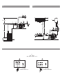
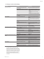
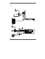
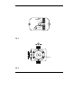
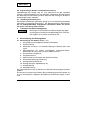
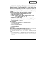
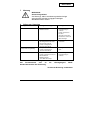
2050754-Ed.02/2009-09-Wilo
Wilo-Jet-WJ
D
Einbau- und Betriebsanleitung
I
Istruzioni di montaggio, uso e manutenzione
GB
Installation and operating instructions
CZ
Návod k montáži a obsluze
F
Notice de montage et de mise en service
RUS Инструкция по монтажу и эксплуатации
NL
Inbouw- en bedieningsvoorschriften
GR
Οδηγίες εγκατάστασης και λειτουργίας
E
Instrucciones de instalación y funcionamiento
TR
Montaj ve kullanma kılavuzu
Fig. 1
Fig. 2
3
7
9
0,5 M MIN.
2 5
7
12
8
13
11
3 x PH.
6
HC
HA
MIN. 200mm
MIN.
100
mm
4
2
10
1
7
4
7
2 5
ou/or
6
Fig. 3
3~
230 - 400 V
220 - 280 V / 240 - 415 V
3 X 400 V
3 X 380 V / 3 X 415 V
3 X 230 V
3 X 220 V / 3 X 240 V
3
7
D
Einbau- und Betriebsanleitung
4
GB
Installation and operating instructions
8
F
Notice de montage et de mise en service
12
NL
Inbouw- en bedieningsvoorschriften
16
E
Instrucciones de instalación y funcionamiento
20
I
Istruzioni di montaggio, uso e manutenzione
24
CZ
Návod k montáži a obsluze
28
RUS
Инструкция по монтажу и эксплуатации
32
GR
Οδηγίες εγκατάστασης και λειτουργίας
36
TR
Montaj ve kullanma kılavuzu
40
Deutsch
1. Allgemeines
Einbau und Inbetriebnahme nur durch Fachpersonal
1.1 Verwendungszweck
Mit der Jetpumpe bietet WILO eine preiswerte
Wasser-Versorgungsanlage für die Bereiche Haus,
Hobby und Garten an. Die Pumpen eignen sich:
– Zum Bewässern und Beregnen aus Teichen,
Bächen und Brunnen,
– Zur Entleerung von Behältern,
– Zum Auspumpen überschwemmter Kellerräume.
Die Pumpe arbeitet im Saugbetrieb (z.B. aus
Brunnen) oder Zulaufbetrieb (z.B. aus offenem
Behälter).
Die Pumpe darf nicht im direkten Anschluss an
das öffentliche Trinkwassernetz angeschlossen
werden.
1.2 Angaben über das Erzeugnis
1.2.1 Anschluss- und Leistungsdaten
Zulässiges Fördermedium: Wasser ohne Fest-/
Sinkstoffe, Brauch-, Kalt-, Kühl- und
Regenwasser. Die Förderung anderer Medien
bedarf der Zustimmung der Firma WILO.
•
•
•
•
•
•
•
•
•
•
Zulässige Temperatur min./max. + 5 °C bis + 35 °C
Umgebungstemperatur min./max. 0...40 °C
Maximale Saughöhe 8 m
1~: 2850 1/min (50 Hz)
3~: 3450 1/min (60 Hz)
Saug- und Druckstutzen DN: RP 1
Max. zulässiger Betriebsdruck 6 bar
Isolationsklasse: 130
Schutzart IP 44
Elektrischer Anschluss 1 ~ 230 V ±6%, 50 Hz /
3 ~ 400 V ±6%, 50 Hz /
1 ~ 220-240 V ±6%, 60 Hz
3 ~ 220-254/380-440 V
±6%, 60 Hz
Bei Ersatzteilbestellungen sind sämtliche Daten
des Anlagentypenschildes anzugeben.
2. Sicherheit
Diese Betriebsanleitung enthält grundlegende
Hinweise, die bei Aufstellung und Betrieb zu
beachten sind. Daher ist diese Betriebsanleitung
unbedingt vor Montage und Inbetriebnahme vom
Monteur sowie dem zuständigen Betreiber zu
lesen. Es sind nicht nur die unter diesem
Hauptpunkt Sicherheit aufgeführten allgemeinen
Sicherheitshinweise zu beachten, sondern auch
die unter den folgenden Hauptpunkten eingefügten, speziellen Sicherheitshinweise.
2.1 Kennzeichnung von Hinweisen in der
Betriebsanleitung
Allgemeines Gefahrensymbol.
Sicherheitshinweise, die bei Nichtbeachtung
Gefährdungen
Warnung vor elektrischer Spannung
ACHTUNG! Sicherheitshinweise, deren
Nichtbeachtung Gefahren für die Pumpe/Anlage
und deren Funktion hervorrufen können.
4
2.2 Personalqualifikation
Das Personal für die Montage muss die entsprechende Qualifikation für diese Arbeiten aufweisen.
2.3 Gefahren bei Nichtbeachtung der
Sicherheitshinweise
Das Nichtbeachten der Sicherheitshinweise kann
eine Gefährdung für Personen und Anlage zur
Folge haben. Die Nichtbeachtung der
Sicherheitshinweise kann zum Verlust jeglicher
Schadenersatzansprüche führen.
Im einzelnen kann Nichtbeachten beispielsweise
folgende Gefährdungen nach sich ziehen:
• Versagen wichtiger Funktionen der Anlage,
• Gefährdungen von Personen durch elektrische
und mechanische Einwirkungen.
2.4 Sicherheitshinweise für den Betreiber
Die bestehenden Vorschriften zur Unfallverhütung sind zu beachten.
Dieses Produkt darf nicht durch Personen mit eingeschränkter Zurechnungsfähigkeit (einschließlich Kindern) oder ohne entsprechendes Fachwissen in Betrieb genommen oder bedient werden. Ausnahmen sind nur durch entsprechende
Anweisung sicherheitsverantwortlicher Personen
zulässig.
Gefährdungen durch elektrische Energie sind auszuschließen. Vorschriften des VDE und der örtlichen Energieversorgungsunternehmen beachten.
2.5 Sicherheitshinweise für Inspektions- und
Montagearbeiten
Der Betreiber hat dafür zu sorgen, dass alle
Inspektions- und Montagearbeiten von autorisiertem und qualifiziertem Fachpersonal ausgeführt werden, das sich durch eingehendes
Studium der Betriebsanleitung ausreichend informiert hat.
Die Arbeiten an der Pumpe/dem Produkt dürfen
nur im Stillstand durchgeführt werden.
2.6 Eigenmächtiger Umbau und
Ersatzteilherstellung
Veränderungen der Anlage sind nur nach
Absprache mit dem Hersteller zulässig.
Originalersatzteile und vom Hersteller autorisiertes Zubehör dienen der Sicherheit. Die
Verwendung anderer Teile kann die Haftung für
die daraus entstehenden Folgen aufheben.
2.7 Unzulässige Betriebsweisen
Die Betriebssicherheit der gelieferten Anlage ist nur
bei bestimmungsmäßiger Verwendung entsprechend Abschnitt 1 der Betriebsanleitung gewährleistet. Die im Datenblatt angegebenen Grenzwerte
dürfen auf keinen Fall überschritten werden.
3. Transport und Zwischenlagerung
ACHTUNG! Die Pumpe darf keinen Temperaturen
außerhalb des Bereiches von 0 °C bis +40 °C ausgesetzt werden.
Wird die gelieferte Pumpe erst zu einem späteren
Zeitpunkt eingebaut, ist sie gegen Feuchtigkeit,
mechanische Beschädigung durch Stoß/Schlag
und allen äußeren Einflüssen zu schützen.
WILO SE 09/2009
Deutsch
Es ist vorsichtig mit der Pumpe umzugehen, so
dass die Geometrie und die Ausrichtung der
Hydraulik nicht verändert werden.
Die Pumpe niemals am Stromkabel aufhängen.
4. Beschreibung von Erzeugnis und
Zubehör
Alle Typen sind selbstansaugende Kreiselpumpen.
Bei den Wechselstrom-Motoren schaltet der
thermische Motorschutz den Motor bei Überlastung ab. Nach Abkühlen des Motors schaltet die
Pumpe sich automatisch wieder ein. Das
Pumpengehäuse ist gegenüber dem Motor mit
einer Gleitringdichtung abgedichtet.
ACHTUNG!! Die Pumpe darf nicht trocken laufen.
Für Schäden an der Pumpe, die durch
Trockenlauf entstehen, erlischt die Garantie des
Herstellers.
4.1 Beschreibung der Pumpe WJ
Die WJ-Typen sind transportable Pumpen. Die
EM-Pumpen haben einen Tragegriff und werden
anschlussfertig mit Anschlusskabel,
Schutzkontaktstecker und Ein-Aus-Schalter
geliefert.
Maximaler Betriebsdruck
– Bild 1: Saugbetrieb
– Bild 2: Druckbetrieb am Vorratstank oder am
Druckwasser- Anschluss mit TrockenlaufSchutz.
Legende für Einbaubeispiele (siehe Bilder 1 und 2):
Pos. 1 Ansaug-Fußventil (maximaler Durchgang
1 mm)
Pos. 2 Ansaug-Kugelhahn
Pos. 3 Auslassventil
Pos. 4 Rückflussverhinderer
Pos. 5 Füllschraube
Pos. 6 Ablassschraube
Pos. 7 Rohrbefestigung
Pos. 8 Ansaugkorb
Pos. 9 Vorratstank
Pos. 10 Wasseranschluss
Pos. 11 3~ Netzanschluss (DM)
Pos. 12 An/Aus-Schalter für 1~-Motor
(rote Signalleuchte)
Pos. 13 Netzstecker (1~ -Motor)
4.2 Lieferumfang
– Jetpumpe (WJ)
– Einbau- und Betriebsanleitung.
4.3 Zubehör
– Ansaugkit,
– Absperrvorrichtung ,
– Rückflussverhinderer,
– Saugkorb-Fußventil,
– Membrandruckbehälter,
– Schwingungsdämpfer,
– Motorschutzrelais,
– Trockenlaufschutz (ME-Kit),
– Ein-/Aus-Schaltgerät
Der Einsatz von neuem Zubehör wird empfohlen.
WILO SE 09/2009
5. Aufstellung/Einbau
5.1 Montage
Die Pumpe gemäß den Vorschriften des örtlichen
Wasser-Versorgungs- Unternehmens betreiben.
Anforderungen an den Aufstellungsort:
– leicht zugänglich
– gut belüftet, trocken und frostsicher
– Montage auf einem Beton-Sockel oder direkt auf
einem glatten ebenen Untergrund.
Folgeschäden, die durch Ausfall der Pumpe entstehen können, wie Überflutung von Räumen,
hat der Betreiber durch geeignete Maßnahmen
(z. B. Installation einer Alarmanlage,
Reservepumpe u.ä.) auszuschließen.
– Saug- und Druckleitung sind bauseits beizustellen.
– Bei Anschluss von festen Saug- und
Druckleitungen ist die Pumpe bauseits am Boden
zu befestigen.
– Bei nicht fixierter Aufstellung ist die Pumpe
zumindest mit flexiblen Schlauch-Übergangsstücken an die Saug- und Druckleitung anzuschließen.
– Die Saugleitung steigend, vakuumdicht und
spannungsfrei verlegen.
– Bei mehr als 5 m Saughöhe sollte der
Durchmesser der Saugleitung mindestens 11/4“
betragen.
– Druckleitung spannungsfrei an Druckstutzen
anschließen.
ACHTUNG! Zur Gewährleistung eines einwandfreien Betriebes benötigen die Pumpen eine
Wasservorlage von 30 cm, d. h. der Anfang der
Druckleitung ist mindestens auf einer Länge von
30 cm steigend zu verlegen.
– An die Saugleitung ist ein Fußventil zu montieren.
Es sollte mindestens 30 cm unter dem niedrigsten Wasserstand liegen. Grundsätzlich ist die
Verwendung eines Saugschlauch- Sets
(Zubehör), bestehend aus Saugschlauch,
Saugkorb und Fußventil zu empfehlen.
5.2 Elektrischer Anschluss
ACHTUNG! Der elektrische Anschluss ist von
einem beim örtlichen EVU zugelassenen
Elektroinstallateur und entsprechend den geltenden VDE-Vorschriften auszuführen.
Die Pumpen sollten nur über einen FehlerstromSchutzschalter von 30 mA angeschlossen werden.
– Für den Einsatz in Schwimmbecken und
Gartenteichen die Vorschriften nach VDE 0100
Teil 702 einhalten.
– Die elektrischen Steckverbindungen überflutungssicher und vor Feuchtigkeit geschützt
installieren.
– Stromart und Spannung des Netzanschlusses
überprüfen.
– Typenschilddaten des Pumpenmotors beachten.
– Netzseitige Absicherung: 10A, träge.
– Erdung beachten.
5
Deutsch
Die Pumpen dürfen nur mit einer elektrischen
Anschlussleitung (auch Verlängerungsleitung)
betrieben werden, die mindestens einer
Gummischlauchleitung vom Typ H07 RNF nach
DIN 57282 oder DIN 57245 ensprechen.
– DM-Motoren nach Bild 3/Anschlussbild im
Klemmenkasten verdrahten.
– Bei Anschluss einer Drehstrommotor-Pumpe ist
ein Motorschutzschalter bauseits vorzusehen.
Er ist auf den Nennstrom lt. Typenschild einzustellen.
– Erden nicht vergessen.
– Ein Anschlussfehler führt zu Motorschaden.
– Das Stromkabel darf niemals das Rohr oder die
Pumpe berühren; der Schutz vor jeglicher
Feuchtigkeit ist sicherzustellen.
6. Inbetriebnahme
– Prüfung auf ausreichenden Wasserstand im offenen Vorlaufbehälter bzw. im Brunnen.
Trockenlauf der Pumpe unbedingt vermeiden!
Er zerstört die Gleitringdichtung.
– Pumpe und Saugleitung an der Einfüllschraube
befüllen. Nur eine befüllte Pumpe ist selbstansaugend.
– Evtl. vorhandene Absperrorgane in der
Druckleitung öffnen, damit evtl. Luft in der
Saugleitung frei herausgefördert werden kann.
– Bei DM-Motoren Drehrichtung kontrollieren:
Durch kurzzeitiges Einschalten prüfen, ob die
Drehrichtung der Pumpe mit dem Pfeil auf der
Lüfterhaube übereinstimmt. Bei falscher
Drehrichtung 2 Phasen vertauschen.
– Die Pumpe niemals am Netzanschlusskabel
anheben, transportieren oder befestigen.
– Die Pumpe darf keinem direkten Wasserstrahl
ausgesetzt werden.
7. Wartung
Vor der Überprüfung Pumpe bzw. Anlage spannungsfrei schalten! Schäden am Anschlusskabel
grundsätzlich durch einen qualifizierten
Elektroinstallateur beheben lassen.
Zur Gewährleistung höchster Betriebssicherheit
bei geringstmöglichen Betriebskosten werden
folgende, gelegentliche Überprüfungen empfohlen:
– Überprüfung des Druckes im
Membrandruckbehälter (mindestens 1,4 bar bei
Standardeinstellung des Druckschalters),
– Pumpe auf Dichtheit prüfen.
Bei Frostgefahr muß die Pumpe komplett (einschließlich Behälter) entleert werden. Der
Entleerungsstopfen befindet sich an der
Pumpenunterseite.
Vor längerem Stillstand (z. B. Überwinterung)
sollte die Pumpe gründlich durchgespült, komplett entleert und dann trocken gelagert werden.
Vor Wiederinbetriebnahme durch kurzes EinAus-Schalten überprüfen, ob die Pumpe frei
dreht. Dann wieder mit Wasser auffüllen.
6
WILO SE 09/2009
Deutsch
8. Störungen, Ursachen und Beseitigung
Störungen
Pumpe läuft nicht an
Ursachen
Unterbrechung in der Stromzuführung,
Kurzschluß, Isolationsfehler in der
Motorwicklung
Beseitigung
Netzspannung überprüfen, Leitung und
Motor vom Fachmann überprüfen lassen
Pumpe ist durch Fremdkörper blockiert (1) – Anlage spannungsfrei schalten und
gegen unbefugtes Wiedereinschalten
sichern
– Absperrarmatur hinter der Pumpe
schließen
– Pumpe aus dem Sumpf herausheben
– Fremdkörper aus der Pumpe entfernen
Motor überhitzt
Thermoschutz- Schalter hat ausgelöst
Pumpe läuft, aber fördert nicht oder zu
wenig
Motorschutzschalter hat ausgelöst
(1 ~ -Motor)
Pumpe/Motor abkühlen lassen
Zu geringe Betriebsspannung
Spannung an den Anschlussklemmen
prüfen.
Sie sollte innerhalb von ± 6 % (50 Hz),
bzw. ± 6 % (60 Hz) der Nennspannung
liegen
Pumpe ist durch äußere Einflüsse
blockiert
(siehe 1)
Umgebungstemperatur über +40 °C
Der Motor ist auf eine maximale
Umgebungstemperatur von +40 °C ausgelegt
Aufstellort > 1000 m
Der Motor ist für ein Betriebsniveau von
≤ 1000 m ausgelegt
Thermo-Schutzschalter falsch eingestellt (3 ~ -Motor)
auf Nennstrom einstellen
Spannung ist zu niedrig
Überprüfen, ob der Kabelquerschnitt ausreichend ist
Eine Phase is unterbrochen
Phasen überprüfen und falls erforderlich
Kabel austauschen
Thermo-Schutzschalter defekt
austauschen
Motor defekt
austauschen
Pumpe ist durch äußere Einflüsse
blockiert
Pumpe leergelaufen
Luft in der Saugleitung
(siehe 1)
Saugleitung verstopft
Falsche Drehrichtung (3 ~ -Motor)
Pumpe vibriert
Bodenverschraubung ist locker
Pumpe ist durch äußere Einflüsse
blockiert
Elektrische Verbindung fehlerhaft
Pumpe füllen
Gesamte Zuleitung bis zur Pumpe auf
Dichtheit prüfen und abdichten
Saugleitung reinigen
2 Phasen des Netzanschlusses vertauschen
Alle Befestigungsbolzen prüfen und festziehen
(siehe 1)
Elektrische Verbindung überprüfen
Eine Verstopfung der Pumpe kann in den meisten Fällen dadurch beseitigt werden, dass
zunächst der Saugschlauch abgenommen und
die Pumpe dann rückwärts unter Druck durchgespült wird. Während des Durchspülens die Pumpe
mehrmals für 2 Sekunden einschalten. Läßt sich
die Betriebsstörung nicht beheben, wenden Sie
sich bitte an das Fachhandwerk oder an die
nächstgelegene WILO-Kundendienststelle oder
Vertretung.
WILO SE 09/2009
7
English
1. General
Installation and service by qualified personnel only
1.1 Application
With the Jet-pump WlLO offers an inexpensive
water supply unit in the fields of home, hobby and
garden. The pumps are suitable for:
– watering and sprinkling from ponds, creeks and
bores,
– draining of tanks and containers,
– dewatering of flooded basements.
The pump works self-priming (e.g. from bores) or
with flooded suction (e.g. from open tanks).
It must not be connected directly to public water
supply systems.
1.2 Product Information
1.2.1 Technical Data
Suitable media: Water without solid particles,
domestic, cold, cooling and rain water. Use of
other media requires WlLO's consent.
•
•
•
•
•
•
•
•
•
•
Temperature min./max. + 5 °C to + 35 °C
Environment temperature min./max. 0...40 °C
Maximum suction lift 8 m
Single-phase (EM): 2850 1/min (50 Hz)
Three-phase (DM): 3450 1/min (60 Hz)
Size suction/discharge ports: 1”BSP
Max. working pressure 6 bar
Insulation class 130
Protection index IP 44
Electrical connection 1 ~ 230 V ±6%, 50 Hz /
3 ~ 400 V ±6%, 50 Hz /
1 ~ 220-240 V ±6%, 60 Hz
3 ~ 220-254/380-440 V
±6%, 60 Hz
When ordering spare parts, please state all name
plate data.
2. Safety
These instructions contain basic rules on safety
which must be strictly adhered to. It is therefore
imperative for the Installer and the Operator to
carefully read these instructions prior to installation and commissioning. Please observe, not only
the safety directions under the main heading
Safety Rules, but also those added and specially
marked under the ensuing headers.
2.1 Safety marks contained in these Instructions
Danger from general causes. Safety references
contained which, if not complied with, may
cause death or severe physical injury to persons.
Danger from electrical causes
ATTENTION! Safety references which, if not
complied with, may result in damage to the plant
or its function.
2.2 Personnel qualification
Only suitably qualified personnel may work on
this equipment .
2.3 Dangers from non-observance of safety hints
Non-observance of safety reference may cause
bodily harm to persons or damage to the plant.
8
Failure to comply with safety reference could
invalidate warranty and/or damage claims.
In detail, non-compliance may, for example,
cause the following dangerous possibilities:
• Failure of vital plant functions or damage to the
pump,
• Causing personal injury due to electrical and/or
mechanical causes.
2.4 Safety reference for the Operator
Local regulations for the prevention of accidents
must be observed.
This appliance is not intended for use by persons
(including children) with reduced physical, sensory or mental capabilities, or lack of experience and
knowledge, unless they have been given supervision or instruction concerning use of the appliance by a person responsible for their safety.
Danger tram electrical energy must be excluded
(conforming to local or general regulations such
as lEG, 881, VDE etc.).
2.5 Safety reference for Inspections and
Installation work
It is the Operator's responsibility to ensure that
inspections and installation work are carried out
by authorized and qualilied personnel only, having
themselves made lully conversant with these
instructions.
Work must principally be carried out only with the
plant switched off and at complete standstill.
2.6 Arbitrary alterations and spare part procurement
Any alterations to the plant are only permitted in
agreement with the manulacturers. Original spare
parts and authorized accessories serve safety and
reliability. The use of unauthorized parts could
invalidate any claims tor consequential damages.
2.7 Abnormal Operating Conditions
Operational salety of the plant is only ensured il
used in accordance with Ghapter 1 of these instructions. The limits stated there must not be exceeded under any circumstances.
3. Transport and Storage
ATTENTION! The pump must not be subjected to
temperatures outside the limits of 0 °C to +
40 °C.
If the equipment delivered is to be installed at
some later time, store it in a dry place and protect it from impacts and all external influences
(moisture, frost, etc.).
Handle the pump carrefully so as not to alter the
geometry and the alignment of the hydraulic
unit.
Never suspend the pump from the power cord.
4. Description of Product and Accessories
All WJ-series pumps are self-priming.AlI parts in
contact with the medium being handled are of
corrosion-resistant steel. Single-phase motors
have built-in thermal contacts, switching off the
motor on overload and on again after a cooling
down period. A mechanical seal separates the
pump housing from the motor.
WILO SE 09/2009
English
ATTENTION! The pump must not run dry.
Warranty does not cover damages to the pu mp
due to dryrunning.
4.1 Description of WJ-Series Pump
Series WJ pumps are portable for mobile application. Single phase pumps have a carrying grip and
are supplied complete with power cable, plug
and ON/OFF switch.
Standard-Installations
– Figure 1: Pump in suction
– Figure 2: Pump under pressure on storage tank or
on town water supply with dry-running protection system.
Legend for Installation samples (see figures 1 and 2):
Pos. 1 Strainer-foot valve (maximum passing
section 1 mm)
Pos. 2 Pump suction valve
Pos. 3 Pump discharge valve
Pos. 4 Non-return valve
Pos. 5 Filling plug
Pos. 6 Draining plug
Pos. 7 Pipe supports
Pos. 8 Strainer
Pos. 9 Storage tank
Pos. 10 Town water supply
Pos. 11 3~ motor protection relay
Pos. 12 OFF/ON switch for single phase motor
(red indicator light)
Pos. 13 Power plug (1~ -Motor)
4.2 Scope of supply
– Jet Pump (WJ)
– Installation and Operation instructions.
4.3 Accessories
– Suction kit,
– Isolating valves,
– Non-return valves,
– Strainer-foot valve,
– Bladder tank,
– Vibrationless sleeves,
– Motor protection relay,
– Dry running protection (ME kit),
– On-off control device...
The use of new accessories is recommended.
5. Sitting/lnstallation
5.1 Installation
The pump must be operated in strict compliance
with local water supply regulations.
Requirements on installation location:
– easy to reach
– well vented, dry and frostfree
– Installation on a concrete socket or directly on a
smooth and horizontal floor.
lt is the Operators responsibility to take all preventive measures (e. g. provision of alarm
systems, standby pump, etc.) to avoid consequential damages such as flooding due to pump
failure.
– Suction and discharge piping to be provided on
site by others.
– When using solid pipe connections the pump
must be firmly fixed to the floor.
– If not firmly fixed, flexible connectors must at
WILO SE 09/2009
least be used for suction and discharge ports.
– The suction pipe must be fully airtight and be
installed free of stress, steadily rising towards the
pump.
– Suction lifts above 5 metres require a suction
pipe size of not less than 11/4”.
– Discharge pipe connections must be free of
stress on the pump.
ATTENTION! In order to ensure proper operation
a static discharge head of 30 cm is required; the
discharge pipe must thus be installed with a rise
of at least 30 cm.
– A foot valve is required at the end of the suction
line. lt must be located not less than 30 cm below
the lowest water level. Recommended is the use
of a suction hose set (optional extra) consisting
of suction hose, suction strainer and foot valve.
5.2 Electrical connection
ATTENTION! All electrical work to be carried out
by a qualified and locally licenced electrician in
strict conformity with locally ruling regulations.
30 mA earth fault circuit interruptors should be
used for the electrical circuits to the pump.
– Regulations of VDE 0100, Part 702 must be
observed for use in conjunction with swimming
pools or garden ponds.
– Electrical plug connections must be made in
flood-safe locations and be protected from moisture.
– Check available power supply.
– Take note of pump name plate data requirements.
– Supply side fuse: 10A, inert action.
– Observe local earthing requirements.
Pumps must only be operated on electrical cables
(also extension leads) conforming with local
ruling standards.
– Three-phase motors to be wired in accordance
with Fig. 3 (motor terminal wiring).
– Three-phase motors require the onsite provision
and installation by others of an external thermal
overload protection device to be set to the F.L.C.
value stated on the motor name plate.
– Do not forget to connect the earth.
– A connection error would damage the motor.
– The power cable must never touch the pipe or
the pump ; make sure that it is sheltered from
any humidity.
6. Commissioning
– Check to ensure that a sufficiently high water
level is available in the open break tank or bore.
Dry-running of the pump must be prevented as it
will lead to destruction of the mechanical seal.
– Fill pump and suction line via the fill plug. Only a
filled pump has self-priming capacity.
– Open discharge isolating valve(s) to allow free air
evacuation from the suction pipe.
– Three-phase motors require a rotation check:
Briefly switch on the pump and check whether
actual direction of rotation corresponds with the
9
English
arrow on the fan hood of the motor. II necessary,
change any two supply phases.
– Never use the power supply cable for lifting,
transporting or fixing of the pump.
– The pump must not be subjected to direct water
spray.
7. Maintenance
Isolate from power supply before checking the
pump!
In principle, damage to the connecting cable
should only be repaired by a qualified electrician.
To ensure highest operational safety and reliability at lowest possible cost the following routine
checks are recommended:
– Check on diaphragm vessel pressure (at least
1.4 bar on standard settings of pressure switch).
– Check pump for leaks.
On danger of freezing it is necessary to completely drain the pump using the drain plug at the
bottom of the pump housing.
For prolonged standdown periods (e. g. winter
shutdown) the pump needs thorough scouring,
complete draining and dry storage.
On re-commissioning check tor free rotation by
brieflyswitching-on the pump. Then re-fill with
water.
10
WILO SE 09/2009
English
8. Faults, Causes and Remedies
Défauts
Pump does not run
Causes
Remèdes
Interruption of the current, short circuit, Check power supply, Call on expert to
Insulation fault in the motor coil
check cable and motor
Pump is blocked due to foreign matters (1) – Switch off the pump voltage and secure against reoperation.
– Close the shut-off fittings at the back
and front of the pump.
– Remove foreign bodies from the pump
Motor overheats
Thermal relay
Pump runs, but no delivery or it
tranports too little
Pump vibrates
Protective motor switch activated
(1 ~ -Motor)
Let the pump/motor cooling
Too low voltage
Check voltage on terminals of the
motor.It should be within ± 6 % (50 Hz),
resp. ± 6 % (60 Hz) of the rated voltage
Pump is blocked due to foreign matters
(see 1)
Ambient temperature above +40 °C
The motor is aimed at operating at
a maximum ambient temperature
of +40 °C
Altitude > 1000 m
Motor is planned to operate at an altitude ≤ 1000 m
Value of the thermal relay (3 ~ -Motor) is Check the current with an ammeter or put
too low
the value switches off of the cuttent rating
mentioned on the motor data plate
Voltage is too low
Check the adequate cross-section of the
electrical cable conductors
A phase is cut
Check it and change the electrical cable if
necessary
Thermal relay of the curcuit-breaker is
defective
replace it
Motor is defective
replace it
Pump is blocked due to foreign matters
(see 1)
Pump is empty
Air in suction pipes
Fill the pump
Check tightness of the whole pipe up to
the pump and make it tight
Suction pie obstructed
Clean all the pipes
Wrong rotating direction(3 ~ -Motor)
Cross two phase wires
Loose on ist foundation
Check and completely tighten the nuts
of the stud bolts
Pump is blocked due to foreign matters
(see 1)
Bad electrical connection
Check the connections to the pump
motor
A blockage of the pump can in most cases be
remedied by removing the suction connection and
scouring the pump backwards under pressure.
Switch-on pump several times for 2 secs during
scouring.
If the fault cannot be located or rectified, please
contact your nearest WILO representative.
WILO SE 09/2009
11
2 049 542 / ed04-0804
Wilo-Fluidcontrol / - EK
D
Montageanleitung
GB
Assembly Instructions
F
Notice de montage
NL
Inbouw- en gebruikshandleiding
E
Instrucciones de instalación y funcionamiento
I
Istruzioni di montaggio, uso e manutenzione
H
Beépítési és üzemeltetési útmutató
GR
Οδηγίες εγκατάστασης και λειτουργίας
2
5
6
3
1
4
Fig. 1
10
11
9
8
12
Fig. 2
Fig. 2
220-240 V
50 - 60 Hz
M
1
L1
N
U
V
Fig. 4
7
Fig. 5
Einbau- und
Betriebsanleitung
Installation and
operating instructions
Notice de montage et
de mise en service
Inbouw- en
gebruikshandleiding
Instrucciones de instalación y
funcionamiento
Istruzioni di montaggio, uso e
manutenzione
Beépítési és
üzemeltetési útmutató
Οδηγίες εγκατάστασης
και λειτουργίας
……..6
D
……12
GB
……18
F
……24
NL
……30
E
……36
I
……42
H
……48
GR
DEUTSCH
1
Allgemeines
Einbau und Inbetriebnahme nur durch Fachpersonal!
1.1
Verwendungszweck
Das elektronische Steuer- und Kontrollsystem Wilo-Fluidcontrol (...EK) wird
auf Einzelpumpen zur Hauswasserversorgung und Druckerhöhung
aufgeschraubt. Er ermöglicht den automatischen Betrieb dieser Pumpen ohne
separaten Druckbehälter.
1.2 Angaben über das Erzeugnis
1.2.1 Anschluß- und Leistungsdaten
Fördermedium
Reines Wasser ohne Sinkstoffe
max. Fördermenge:
10 m³/h
max. zul. Betriebsdruck:
10 bar
Einschaltdruck:
max. zul. Wassertemperatur:
1,5 - 2,7 bar
60 °C
Anschlußspannung:
Wechselstrom
Nennstrom:
max. 10 A
Schutzart:
IP 65
Anschluß Saug-/Druckleitung:
R1
1 ~ 220 - 250 V, 50 - 60 Hz
Der von der verwendeten Pumpe erzeugte Druck muß ca. 0,5 bar über dem
Einschaltdruck, d.h. > 2,0 bar liegen.
Bei Ersatzteilbestellungen sind sämtliche Daten des Anlagentypenschildes
anzugeben.
2
Sicherheit
Diese Betriebsanleitung enthält grundlegende Hinweise, die bei Aufstellung
und Betrieb zu beachten sind. Daher ist diese Betriebsanleitung unbedingt vor
Montage und Inbetriebnahme vom Monteur sowie dem zuständigen Betreiber
zu lesen. Es sind nicht nur die unter diesem Hauptpunkt Sicherheit
aufgeführten allgemeinen Sicherheitshinweise zu beachten, sondern auch die
unter
den
folgenden
Hauptpunkten
eingefügten,
speziellen
Sicherheitshinweise.
6 (55)
DEUTSCH
2.1 Kennzeichnung von Hinweisen in der Betriebsanleitung
Die in dieser Betriebsanleitung enthaltenen Sicherheitshinweise, die bei
Nichtbeachtung Gefährdungen für Personen hervorrufen können, sind mit dem
allgemeinen Gefahrensymbol
bei Warnung vor elektrischer Spannung mit
besonders gekennzeichnet.
Bei Sicherheitshinweisen, deren Nichtbeachtung Gefahren für die Anlage und
deren Funktion hervorrufen können, ist das Wort
ACHTUNG!
eingefügt.
2.2 Personalqualifikation
Das Personal für die Montage muß die entsprechende Qualifikation für diese
Arbeiten aufweisen.
2.3 Gefahren bei Nichtbeachtung der Sicherheitshinweise
Die Nichtbeachtung der Sicherheitshinweise kann eine Gefährdung für
Personen und Anlage zur Folge haben. Die Nichtbeachtung der
Sicherheitshinweise kann zum Verlust jeglicher Schadenersatzansprüche
führen.
Im einzelnen kann Nichtbeachtung beispielsweise folgende Gefährdungen
nach sich ziehen:
●
Versagen wichtiger Funktionen der Anlage,
●
Gefährdungen von Personen durch elektrische und mechanische
Einwirkungen.
2.4 Sicherheitshinweise für den Betreiber
Die bestehenden Vorschriften zur Unfallverhütung sind zu beachten.
Gefährdungen durch elektrische Energie sind auszuschließen. Vorschriften
des VDE und der örtlichen Energieversorgungsunternehmen beachten.
2.5 Sicherheitshinweise für Inspektions- und Montagearbeiten
Der Betreiber hat dafür zu sorgen, daß alle Inspektions- und Montagearbeiten
von autorisiertem und qualifiziertem Fachpersonal ausgeführt werden, das
sich durch eingehendes Studium der Betriebsanleitung ausreichend informiert
hat.
Grundsätzlich dürfen Arbeiten an der Anlage nur im Stillstand durchgeführt
werden.
7 (55)
DEUTSCH
2.6 Eigenmächtiger Umbau und Ersatzteilherstellung
Veränderungen der Anlage sind nur nach Absprache mit dem Hersteller
zulässig. Originalersatzteile und vom Hersteller autorisiertes Zubehör dienen
der Sicherheit. Die Verwendung anderer Teile kann die Haftung für die daraus
entstehenden Folgen aufheben.
2.7 Unzulässige Betriebsweisen
Die Betriebssicherheit der gelieferten Anlage ist nur bei bestimmungsmäßiger
Verwendung entsprechend Abschnitt 1 der Betriebsanleitung gewährleistet.
Die im Katalog/Datenblatt angegebenen Grenzwerte dürfen auf keinen
Fall unter- bzw. überschritten werden.
3
Transport und Zwischenlagerung
ACHTUNG!
Die Anlage ist bei Transport und Zwischenlagerung gegen
Feuch-tigkeit und mechanische Beschädigung zu schützen.
Der Lagerort muss trocken und frostfrei sein.
4
Beschreibung des Erzeugnisses
4.1 Beschreibung des Gerätes (Bilder 1 & 2)
1. Saug-Öffnung mit integriertem Rückflussverhinderer
2. Auslass-Öffnung
3. Manometer (0-10 bar) zur Kontrolle; Montage wahlweise links oder
rechts
4. Klemmenkasten mit Platine einschließlich Trockenlauf-Schutz,
elektrischem Anschluss der Pumpe und Netzanschluss
5. Druckkammer mit Membran
6. Ausgleichskammer
7. Stellschraube zum Einstellen des Einschalt-Druckes
8. Reset-Knopf (Störungs-Quittierung)
9. Anzeige (Netz ein/Power on)
10. Anzeige (Pumpe in Betrieb/Pump on)
11. Anzeige Störung
12. Manometer-Achse
Das Wilo-Fluidcontrol wird als Zubehör für Wilo-Wasserversorgungs-Pumpen
geliefert.
Das Gerät muß auf die Pumpe oder in die Druckleitung geschraubt werden. Es
ist in In-line-Bauweise ausgeführt, die beiden Anschlußstutzen liegen in einer
Linie.
8 (55)
DEUTSCH
In betriebsbereitem Zustand, bei geschlossener Leitung und maximalem
Betriebsdruck ist die Pumpe abgeschaltet, die grüne LED leuchtet (Pos. 9).
Im Gerät ist ein kleiner Vorratsraum mit Wasser, der über eine federgespannte
Membran veränderlich ist. Bei Druckänderungen im System bewegt sich die
Membran und verhindert dadurch Druckstöße bei den Schaltvorgängen. Wird
ein Wasserhahn im System geöffnet, so strömt Wasser aus dem kleinen
Vorratsvolumen in die Druckleitung und hebt dabei den Strömungswächter an.
Der Betrieb der Pumpe wird durch Leuchten der gelben Diode (Pos. 10)
angezeigt.
Die Bedienelemente auf dem Klemmenkastendeckel sind (Bild 2):
●
grüne LED: Netzspannung liegt an, betriebsbereit, (Pos. 9)
●
gelbe LED: Pumpe läuft, (Pos. 10)
●
rote LED: Störung, und zwar alle, die zum Druckverlust im System
führen (Wassermangel), (Pos. 11)
● Störquittiertaste (Reset), (Pos. 8)
Nach Beseitigung der Störung muß die Resettaste solange gedrückt
gehalten werden, bis der Druck im System aufgebaut ist. Dasselbe gilt für
den Neuanlauf. Sonst geht bei noch nicht ausreichendem Druck die
Pumpe sofort wieder auf Störung.
4.2 Lieferumfang
●
Fluidcontrol-Gerät (EK-Ausführung: + integrierter Stecker +
1,5 m Anschlusskabel)
●
Einbau- und Betriebsanleitung
5
Aufstellung/Einbau
5.1 Montage
Die Aufstellungs- und Montagebedingungen der Pumpenanlage sind der
Einbau- und Betriebsanleitung der Pumpe zu entnehmen.
Der Richtungspfeil auf dem Gehäuse zeigt die Fließrichtung an.
Das Fluidcontrol-Gerät darf nur in eine senkrechte Druckleitung montiert
werden.
●
Das Fluidcontrol-Gerät mit geeigneten Rohrverbindungs-Elementen auf
dem Druckstutzen der Pumpe aufschrauben, mit Hanf oder Teflonband
eindichten.
9 (55)
DEUTSCH
●
Beträgt die Wassersäulenhöhe zwischen Pumpe und der höchsten
Zapfstelle mehr als 15 m, so muß das Gerät so in die Druckleitung
eingebaut werden, daß die Höhendifferenz von max. 15 m eingehalten
wird. Dabei darf unterhalb des Fluidcontrol-Gerätes aber keine Zapfstelle
installiert werden (Bild 3).
●
Damit die Laufgeräusche der Pumpe nicht auf die Wasserleitung
übertragen
werden,
ist
der
Einbau
eines
flexiblen
Schauchübergangsstückes über dem Fluidcontrol-Gerät zu empfehlen.
5.2 Elektrischer Anschluß
WARNUNG!
Stromschlag-Gefahr!
●
●
●
●
●
●
●
●
6
Der elektrische Anschluß ist von einem beim örtlichen EVU
zugelassenen Elektroinstallateur und entsprechend den
geltenden VDE-Vorschriften auszuführen.
Stromart und Spannung des Netzanschlusses überprüfen,
Typenschilddaten der Pumpe beachten,
Netzanschlußkabel für EM: 3 x 1,5 mm² (Kabeldurchmesser min. 6 mm,
max. 9 mm).
Um den Tropfwasserschutz und die Zugentlastung der Stopfbuchse
sicherzustellen,
eine
Anschlußleitung
mit
ausreichendem
Außendurchmesser verwenden (z.B. 05 VV-F 3 (7) G 1,5 oder AVMH-I 3
(7) x 1,5).
Den Anschluß entsprechend Bild 4 ausführen (Schaltskizze unter dem
Klemmenkastendeckel).
Netzseitige Absicherung: 10 A, träge,
Erdung beachten,
Falls notwendig, einen Fehlerstrom-Schutzschalter (FI-Schalter)
vorsehen.
Inbetriebnahme
Die erforderlichen Einstellungen und Inbetriebnahmebedingungen sind der
Einbau- und Betriebsanleitung der Pumpe zu entnehmen.
Vor Inbetriebnahme der Anlage ist darauf zu achten, daß eine ausreichende
Ansaugung der Pumpe gewährleistet ist bzw. die Pumpe gefüllt ist.
10 (55)
DEUTSCH
7
Wartung
WARNUNG!
Stromschlag-Gefahr!
Vor Wartungs- oder Instandsetzungsarbeiten Anlage
spannungsfrei schalten und gegen unbefugtes
Wiedereinschalten sichern.
8
Störungen, Ursachen
Störungen
Ursache geräteabhängig
Ursache geräteunabhängig
Pumpe startet nicht
- Leiterplatte defekt
- Membran defekt
- Netzausfall
- Förderleistung zu
schwach
- Pumpe mechanisch
blockiert
- Anschlüsse des WiloFluidcontrol vertauscht
- Wassermangel
Pumpe schaltet nicht ab
-
Leiterplatte defekt
Strömungswächter blockiert
Reset-Taste gesperrt
Pumpe erzeugt keinen
ausreichenden Druck
- Leiterplatte defekt
- Pumpe erzeugt keinen
ausreichenden Druck
- Leckage-Verlust
> 0,6 l/min
- Leiterplatte defekt
- Pumpe erzeugt einen Druck <
Einschaltdruck
- Membran defekt
- siehe EBA der Pumpe
- Wassermangel
- Förderleistung zu
schwach
Pumpe läuft unregelmäßig
Pumpe blockiert
- Leckage-Verlust > 0,6
l/min
Läßt sich die Betriebsstörung nicht beheben, wenden Sie sich bitte an
das
Fachhandwerk
oder
an
die
nächstgelegene
WILOKundendienststelle oder Vertretung.
Technische Änderung vorbehalten!
11 (55)
ENGLISH
1
General
Installation and service by qualified personnel only!
1.1 Application
The electronic control system Wilo-Fluidcontrol (... EK) can be screw-attached
to water supply and pressure booster pumps. It enables the automatic
operation of these pumps without use of a separate pressure vessel.
1.2 Product Information
1.2.1 Technical Data
Flow medium
Max. capacity
Max. working pressure
Switch on pressure
Max. water temperature:
Power supply:
F.L.C.
Enclosure:
Connections suction/discharge
clean water free of suspended matter
3
10 m /h
10 bar
1.5 - 2.7 bar
60° C
Single phase
1~ 220-250V,
50-60 Hz
max. 10 A
IP 65
1" BSP
The shut-off head generated by the applicable pump must be approx. 0.5 bar
higher than the 2.2 bar switch-off pressure.
State all name plate data when ordering spare parts.
2
Safety Notes
These instructions contain basic rules on safety which must be strictly adhered
to on installation and operation. It is therefore imperative for the Installer and
the Operator to read these instructions prior to installation and commissioning.
Please observe, not only the general safety references listed under the main
heading SAFETY NOTES, but also those added to and specially highlighted
under the ensuing headers.
12 (55)
ENGLISH
2.1 Safety symbols contained herein
Safety notes contained herein which, if not strictly adhered to, may cause injury
to persons are specially highlighted by general danger symbol:
Warnings from electrical causes by the special symbol:
Safety references which, if not complied with, may result in damage to the plant
or its function are marked by the word:
ATTENTION!
2.2 Trade Qualifications
Only suitably qualified personnel may work on this equipment.
2.3 Hazards arising from non-compliance with safety notes
Non compliance with safety notes may cause bodily harm to persons or
damage to the plant. Failure to comply with safety notes may invalidate any
damage claims. Non-compliance may, for example, lead to the following
hazardous consequences:
●
failure of vital plant functions,
●
hazards to persons due to electrical and/or mechanical causes.
2.4 Safety notes for the Operator
Local regulations regarding the prevention of accidents must be observed.
Hazards from electrical energy must be excluded (conforming to local or
general regulations such as EC, BSI, UL, VDE, etc.).
2.5 Safety rules for inspections and installation work.
It is the Operator's responsibility to ensure that inspection and installation
works are carried out by authorized and qualified personnel only, after
having made themselves fully conversant with these instructions.
Work on this plant must on principle be carried out with the plant switched off
and completely pressure-relieved.
The safety valve must not be removed.
2.6 Arbitrary alterations and spare part procurement
Any alterations to the plant are only permitted with the manufacturers' consent.
Original and manufacturer authorized spare parts serve safety. The use of
other parts can invalidate any claims for consequential damages.
13 (55)
ENGLISH
2.7 Non-permissible operating conditions
Operational safety of the plant is conditional on it being used in accordance
with Chapter 1 of these instructions. Operational criteria must not exceed or
fall short of the limits stated in catalogue/data sheets.
3
Transport and Storage
ATTENTION!
During transport and intermediate storage it is necessary
to protect the WILO-Fluidcontrol from moisture and
mechanical damage.
The stock location must be dry and be frost-free.
4
4.1
1.
2.
3.
4.
5.
6.
7.
8.
9.
10.
11.
12.
Description of the Product
Description of the Device (Fig. 1 & 2)
Suction port with integrated non-return valve
Delivery port
Pressure gauge (0-10 bars) for control – possible mounting on right or left
side.
Electric box with electronic board including a protection against dry
running with motor stop and connection box for pump and network.
Hydraulic chamber with diaphragm.
Compensating chamber with spring.
Adjusting screw for starting pressure of the pump.
Reset button (Störungs-quittierung/Reset).
Indicator light of the voltage (Netz/Power on).
Indicator light for pump running (Pumpe in Betrieb/Pump on).
Indicator light for activating the safety device (Störung/Failure)
Pressure gauge axis
The WILO-Fluidcontrol is offered as ancilliary equipment for WILO water
supply pumps.
The unit must be screwed onto the pump or into the discharge pipe. It is of
Inline design, with both connections axially in line.
On ready standby, with all outlet fitting closed and under max. system pressure,
the yellow LED is on (pos. 9).
The unit contains a small buffer space filled with water which can be varied by
means of a spring-tensioned diaphragm. If an outlet tap in the system is
opened water will flow out of the small buffer volume into the discharge pipe,
lifting the float.
14 (55)
ENGLISH
The green diode (pos. 10) indicates normal pump operation.
The switch unit contains the electronic as well as the terminal block for power
supply and pump motor. The signal/operating elements at the switchbox cover
are (Fig. 2)
●
Yellow LED: Mains power is on, the pump is on ready standby, (pos. 9)
●
Green LED: Pump runs, (pos. 10)
●
Red LED:
Any
fault
leading
to
pressure
loss
in
the
pipe system, (pos. 11)
●
Reset button:After fault rectification the reset button (pos. 8) must be kept
pushed until the system is fully pressurized. This is also valid for renewed
start-up, otherwise the pump will again fail due to insufficient system
pressure.
4.2 Scope of Supply
●
Wilo-Fluidcontrol (EK-series + integrated socket + 1.5 m connecting
cable).
●
Installation and Operating Instructions.
5
Siting/Installation
5.1 Installation
For installation and mounting requirements refer to the pump installation and
operating instructions.
The arrow at the housing indicates direction of flow.
The WILO-Fluidcontrol must only be mounted into a vertically run discharge
pipe.
●
The WILO-Fluidcontrol to be screwed onto the discharge port of the pump
using
suitable connecting fittings, to be sealed with hemp or Teflon band.
●
If the water column between pump and highest outlet tap exceeds 15 m,
the unit must be installed at a higher level in the discharge pipe ensuring
a maximum vertical head onto the unit of not more than 15 m. In such
case no outlet tap must be located at a level below that of the WILOFluidcontrol (Fig. 3).
●
In order to avoid noise transmission from the pump onto the pipe system
it is recommended to provide and install a flexible connector at the
discharge side of theWILO-Fluidcontrol.
15 (55)
ENGLISH
5.2 Electrical Wiring
●
●
●
●
●
●
●
●
6
All electrical site works to be carried out by qualified and
locally licenced electricians strictly in accordance with locally
ruling regulations.
Check available power supply,
take note of pump name plate data requirements,
power wiring 3 x 1.5 mm". (Minimum cable size 6 mm, maximum 9 mm
OD).
To ensure water tightness and pull-force relief from the cable glands the
power
cable must be of sufficient outside diameter (e.g. 05 VV-F 3 (7) G 1,5
oder AVMH-I 3 (7) x 1,5).
All electrical wiring to be executed according to Fig.4.
Supply side fuse: see as for pump; maximum however 10 A, inert.
Strictly adhere to local earthing regulations.
If required (see VDE 0100), a ground fault circuit interruptor (GFCI)switch
must be provided and installed by others.
Commissioning
For possibly required prestart and commissioning procedures for the pump
refer to the separate installation and Operating Instruction for the pump.
Before initial start-up it must be ensured that sufficient suction capability is
available and that the pump is primed and filled.
On initial start-up the pump will run for 8 seconds, after that a renewed start-up
can be effected by keeping the reset button pushed.
7
Maintenance
Warning!
Electrical Shock Hazard!
Prior to maintenance or repair work turn off the pump and
ensure that it is not turned on by unauthorised personnel.
16 (55)
ENGLISH
8
Faults, Causes
Fault
Unit-related Cause
Unit-unrelated Cause
Pump does not start
- defect printed circuit board
- defect diaphragm
-
Pump does not stop
- defect printed circuit board
- jammed flow controller - stuck
reset button
- Pump does not generate sufficient
pressure
- defekt printed circuit board
- Pump does not generate sufficient
pressure (air)
- Leakage loss greater than 0.6
l/min
- defect printed circuit board
- pump generates pressure < start
pressure
- defect diaphragm
- refer to Installation & Maintenance
Instr. of the pump
- Lack of water at suction side
- Pump capacity too low
Pump runs irregularly
Pump is jammed
Power failure
Pump capacity too low
Pump mechanically jammed
WILO-Fluidcontrol wrongly
connected
- Lack of water at suction side
- Leakage loss greater than 0.6
l/min
If the fault cannot be located or rectified, please contact your nearest
Wilo representative.
Technical modifications reserved!
17 (55)
WILO SE 01/2009
WILO SE
Nortkirchenstraße 100
44263 Dortmund
Germany
T +49 231 4102-0
F +49 231 4102-7363
[email protected]
www.wilo.com
Wilo – International (Subsidiaries)
Argentina
WILO SALMSON
Argentina S.A.
C1270ABE Ciudad
Autónoma de Buenos Aires
T +54 11 43015955
[email protected]
Austria
WILO Pumpen
Österreich GmbH
1230 Wien
T +43 507 507-0
[email protected]
Azerbaijan
WILO Caspian LLC
1065 Baku
T +994 12 5962372
[email protected]
Belarus
WILO Bel OOO
220035 Minsk
T +375 17 2503393
[email protected]
Belgium
WILO SA/NV
1083 Ganshoren
T +32 2 4823333
[email protected]
Bulgaria
WILO Bulgaria Ltd.
1125 Sofia
T +359 2 9701970
[email protected]
Croatia
WILO Hrvatska d.o.o.
10090 Zagreb
T +38 51 3430914
[email protected]
Czech Republic
WILO Praha s.r.o.
25101 Cestlice
T +420 234 098711
[email protected]
Denmark
WILO Danmark A/S
2690 Karlslunde
T +45 70 253312
[email protected]
Estonia
WILO Eesti OÜ
12618 Tallinn
T +372 6509780
[email protected]
Finland
WILO Finland OY
02330 Espoo
T +358 207401540
[email protected]
France
WILO S.A.S.
78390 Bois d'Arcy
T +33 1 30050930
[email protected]
Canada
WILO Canada Inc.
Calgary, Alberta T2A 5L4
T +1 403 2769456
[email protected]
Great Britain
WILO (U.K.) Ltd.
DE14 2WJ BurtonUpon-Trent
T +44 1283 523000
[email protected]
China
WILO China Ltd.
101300 Beijing
T +86 10 80493900
[email protected]
Greece
WILO Hellas AG
14569 Anixi (Attika)
T +302 10 6248300
[email protected]
Hungary
WILO Magyarország Kft
2045 Törökbálint
(Budapest)
T +36 23 889500
[email protected]
Ireland
WILO Engineering Ltd.
Limerick
T +353 61 227566
[email protected]
Italy
WILO Italia s.r.l.
20068 Peschiera
Borromeo (Milano)
T +39 25538351
[email protected]
Kazakhstan
WILO Central Asia
050002 Almaty
T +7 727 2785961
[email protected]
Korea
WILO Pumps Ltd.
621-807 Gimhae
Gyeongnam
T +82 55 3405800
[email protected]
Latvia
WILO Baltic SIA
1019 Riga
T +371 67 145229
[email protected]
Lebanon
WILO SALMSON
Lebanon
12022030 El Metn
T +961 4 722280
[email protected]
Lithuania
WILO Lietuva UAB
03202 Vilnius
T +370 5 2136495
[email protected]
The Netherlands
WILO Nederland b.v.
1551 NA Westzaan
T +31 88 9456 000
[email protected]
Norway
WILO Norge AS
0975 Oslo
T +47 22 804570
[email protected]
Poland
WILO Polska Sp. z.o.o.
05-090 Raszyn
T +48 22 7026161
[email protected]
Portugal
Bombas Wilo-Salmson
Portugal Lda.
4050-040 Porto
T +351 22 2080350
[email protected]
Romania
WILO Romania s.r.l.
077040 Com. Chiajna
Jud. Ilfov
T +40 21 3170164
[email protected]
Russia
WILO Rus ooo
123592 Moscow
T +7 495 7810690
[email protected]
Serbia and Montenegro
WILO Beograd d.o.o.
11000 Beograd
T +381 11 2851278
[email protected]
Slovakia
WILO Slovakia s.r.o.
82008 Bratislava 28
T +421 2 45520122
[email protected]
Slovenia
WILO Adriatic d.o.o.
1000 Ljubljana
T +386 1 5838130
[email protected]
South Africa
Salmson South Africa
1610 Edenvale
T +27 11 6082780
errol.cornelius@
salmson.co.za
Spain
WILO Ibérica S.A.
28806 Alcalá de Henares
(Madrid)
T +34 91 8797100
[email protected]
Sweden
WILO Sverige AB
35246 Växjö
T +46 470 727600
[email protected]
Taiwan
WILO-EMU Taiwan Co. Ltd.
110 Taipeh
T +886 227 391655
nelson.wu@
wiloemutaiwan.com.tw
Turkey
WILO Pompa Sistemleri
San. ve Tic. A.S¸.
34530 Istanbul
T +90 216 6610211
[email protected]
Ukraina
WILO Ukraina t.o.w.
01033 Kiew
T +38 044 2011870
[email protected]
Vietnam
Pompes Salmson Vietnam
Ho Chi Minh-Ville Vietnam
T +84 8 8109975
[email protected]
United Arab Emirates
WILO ME - Dubai
Dubai
T +971 4 3453633
[email protected]
USA
WILO-EMU USA LLC
Thomasville,
Georgia 31792
T +1 229 5840097
[email protected]
Saudi Arabia
WILO ME - Riyadh
Riyadh 11465
T +966 1 4624430
[email protected]
Switzerland
EMB Pumpen AG
4310 Rheinfelden
T +41 61 83680-20
[email protected]
USA
WILO USA LLC
Melrose Park, Illinois 60160
T +1 708 3389456
mike.easterley@
wilo-na.com
Wilo – International (Representation offices)
Algeria
Bad Ezzouar, Dar El Beida
T +213 21 247979
[email protected]
Bosnia and Herzegovina
71000 Sarajevo
T +387 33 714510
[email protected]
Macedonia
1000 Skopje
T +389 2 3122058
[email protected]
Moldova
2012 Chisinau
T +373 2 223501
[email protected]
Tajikistan
734025 Dushanbe
T +992 37 2232908
[email protected]
Uzbekistan
100015 Tashkent
T +998 71 1206774
[email protected]
Armenia
375001 Yerevan
T +374 10 544336
[email protected]
Georgia
0179 Tbilisi
T +995 32 306375
[email protected]
Mexico
07300 Mexico
T +52 55 55863209
[email protected]
Rep. Mongolia
Ulaanbaatar
T +976 11 314843
[email protected]
Turkmenistan
744000 Ashgabad
T +993 12 345838
[email protected]
January 2009
WILO SE
Nortkirchenstraße 100
44263 Dortmund
Germany
T 0231 4102-0
F 0231 4102-7363
[email protected]
www.wilo.de
Wilo-Vertriebsbüros in Deutschland
G1 Nord
WILO SE
Vertriebsbüro Hamburg
Beim Strohhause 27
20097 Hamburg
T 040 5559490
F 040 55594949
[email protected]
G3 Sachsen/Thüringen
WILO SE
Vertriebsbüro Dresden
Frankenring 8
01723 Kesselsdorf
T 035204 7050
F 035204 70570
[email protected]
G5 Südwest
WILO SE
Vertriebsbüro Stuttgart
Hertichstraße 10
71229 Leonberg
T 07152 94710
F 07152 947141
[email protected]
G2 Ost
WILO SE
Vertriebsbüro Berlin
Juliusstraße 52–53
12051 Berlin-Neukölln
T 030 6289370
F 030 62893770
[email protected]
G4 Südost
WILO SE
Vertriebsbüro München
Adams-Lehmann-Straße 44
80797 München
T 089 4200090
F 089 42000944
[email protected]
G6 Rhein-Main
WILO SE
Vertriebsbüro Frankfurt
An den drei Hasen 31
61440 Oberursel/Ts.
T 06171 70460
F 06171 704665
[email protected]
Kompetenz-Team
Gebäudetechnik
WILO SE
Nortkirchenstraße 100
44263 Dortmund
T 0231 4102-7516
T 01805 R•U•F•W•I•L•O*
7•8•3•9•4•5•6
F 0231 4102-7666
Kompetenz-Team
Kommune
Bau + Bergbau
WILO EMU GmbH
Heimgartenstraße 1
95030 Hof
T 09281 974-550
F 09281 974-551
Erreichbar Mo–Fr von 7–18 Uhr.
–Antworten auf
– Produkt- und Anwendungsfragen
– Liefertermine und Lieferzeiten
–Informationen über Ansprechpartner vor Ort
–Versand von Informationsunterlagen
* 14 Cent pro Minute aus dem deutschen Festnetz
der T-Com. Bei Anrufen aus Mobilfunknetzen
sind Preisabweichungen möglich.
Werkskundendienst
Gebäudetechnik
Kommune
Bau + Bergbau
Industrie
WILO SE
Nortkirchenstraße 100
44263 Dortmund
T 0231 4102-7900
T 01805 W•I•L•O•K•D*
9•4•5•6•5•3
F 0231 4102-7126
[email protected]
Erreichbar Mo–Fr von
7–17 Uhr.
Wochenende und feiertags
9–14 Uhr elektronische
Bereitschaft mit
Rückruf-Garantie!
–Kundendienst-Anforderung
–Werksreparaturen
–Ersatzteilfragen
–Inbetriebnahme
–Inspektion
–Technische Service-Beratung
–Qualitätsanalyse
Wilo-International
Österreich
Zentrale Wien:
WILO Pumpen Österreich GmbH
Eitnergasse 13
1230 Wien
T +43 507 507-0
F +43 507 507-15
Vertriebsbüro Salzburg:
Gnigler Straße 56
5020 Salzburg
T +43 507 507-13
F +43 507 507-15
Vertriebsbüro Oberösterreich:
Trattnachtalstraße 7
4710 Grieskirchen
T +43 507 507-26
F +43 507 507-15
Schweiz
EMB Pumpen AG
Gerstenweg 7
4310 Rheinfelden
T +41 61 83680-20
F +41 61 83680-21
G7 West
WILO SE
Vertriebsbüro Düsseldorf
Westring 19
40721 Hilden
T 02103 90920
F 02103 909215
[email protected]
Standorte weiterer
Tochtergesellschaften
Argentinien, Aserbaidschan,
Belarus, Belgien, Bulgarien,
China, Dänemark, Estland,
Finnland, Frankreich,
Griechenland, Großbritannien,
Irland, Italien, Kanada,
Kasachstan, Korea, Kroatien,
Lettland, Libanon, Litauen,
Niederlande, Norwegen,
Polen, Portugal, Rumänien,
Russland, Saudi-Arabien,
Schweden, Serbien und
Montenegro, Slowakei,
Slowenien, Spanien,
Südafrika, Taiwan,
Tschechien, Türkei, Ukraine,
Ungarn, Vereinigte Arabische
Emirate, Vietnam, USA
Die Adressen finden Sie unter
www.wilo.de oder
www.wilo.com.
Stand Januar 2009