1
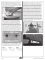
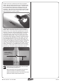
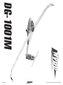
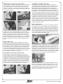
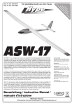
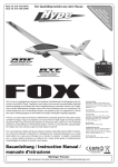
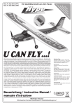
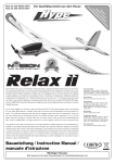
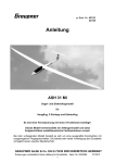
DG-1001M Die DG-1001M ist ein vorbildgetreuer Nachbau des beliebten Hochleistungsseglers der Firma DG-Flugzeugbau in Bruchsal. Das Modell ist mit einem innovativen Klapptriebwerk ausgestattet, das sich automatisch ein- und ausfährt. Im eingefahrenen Zustand verschwindet das Triebwerk vollständig im Rumpf. Rumpf, Tragflächen und Leitwerk sind aus dem neuentwickelten Werkstoff Hypodur® gefertigt und verfügen über hohe Festigkeitswerte bei minimalem Gewicht. Die Tragflächen und das Höhenleitwerk verfügen zudem über einen Kohlefaser-Holm zur Verstärkung. Durch den hohen Vorfertigungsgrad ist das Modell mit wenigen Handgriffen flugfertig aufgebaut. The DG-1001M is a scale replica of the famous HiPerformance glider from the well knwon German company DG-Flugzeugbau, placed in Bruchsal. The model is equipped with an innovative propeller drive that retracts automatically. When the drive is retracted the whole propeller unit disappears into the fuselage. Fuselage, wings and stabilizers are made of the new light weight and strong material Hypodur®. Main wing and horizontal stabilizer are reinforced with a carbon bar. The DG-1001M is more than 90% preassembled. So it takes only a few minutes to get the model ready for take off. DG-1001M è la riproduzione in scala del famoso aliante omonimo costruito dalla ditta tedesca DG Flugzeugbau situata a Bruchsal/Germania. Il modello è dotato di un'innovativa elica retrattile che scompare totalmente nella fusoliera. Fusoliera, ali e impennaggi sono realizzati in Hypodur®, un nuovo materiale leggero e robusto. L'ala e il piano di quota sono rinforzati con aste in carbonio. DG-1001M viene consegnato premontato al 90%. Bauanleitung / Instruction Manual / manuale d'istruzione Wichtiger Hinweis: n. re t s ein ne ah se k ig J ie t e 4 D ll is ge b 1 e g, r a od u le M lze ort ie p Sp ells od rM Ein Qualitätsprodukt aus dem Hause fü Best.-Nr. 018-1525 (ARF) Best.-Nr. 018-1526 (RTF) Technische Daten Spannweite: 2.010 mm; Länge: 970 mm; Flächeninhalt: 22,5 dm²; Gewicht ca.: 750 g; Motor: Brushless; Akku: LiPo 11,1V (RTF); RC-Anlage: 5-Kanal 2.4GHz (RTF); Maßstab ca.: 1:9,9 RC-Funktionen Höhenruder, Seitenruder, Querruder, Motor Technical Data Wingspan: 2.010 mm; Length: 970 mm; Wing Area: 22,5 dm²; Weight approx.: 750 g; Motor: Brushless; Battery: LiPo 11,1V (RTF); RC-System: 5-Channel 2.4GHz (RTF); Scale approx.: 1:9,9 RC-Functions Elevator, Rudder, Aileron, Motor Caratteristiche tecniche apertura alare: 2.010 mm; lunghezza: 970 mm; superficie alare: 22,5 dm²; peso circa.: 750 g; motore: Brushless; batteria: LiPo 11,1V (RTF); radiocomando: 5 canali (RTF); scala circa.: 1:9,9 RC-Functions ITA piano di quota, direzionale, alettoni, motore 0678 ! Zugelassen für / approved for: AT•BE•DE•DK•IT•NL Bitte bewahren Sie diese Dokumentation für Ersatzteilbestellungen auf. 1. Inhaltsverzeichnis / Content / Indice 1. Inhaltsverzeichnis / Content / indice 2. RC-Anlage / Radio System / impianto radio 3. LiPo-Akku & Ladegerät / LiPo-Battery & Charger / batteria LiPo e caricabatterie 4. Zusammenbau / Assembly / assemblaggio 5. Hinweise zur Bedienung / How To Use / l'utilizzo 6. Sicherheitshinweise / Safety Instructions / per la vostra sicurezza 7. Ersatzteile / Spare Parts / ricambi 8. Garantiebedingungen / Warranty / garanzia • Verwendung der Funkanlage / Usage Of The Radio System / L'uso dell'impianto radio Die in diesem Set enthaltene Funkfernsteuerung darf ausschließlich zum Betrieb des im Set enthaltenen Modells verwendet werden. Modifikationen jeglicher Art sind nicht zulässig. The radio system is designed exclusively for steering the included model within this set. It is not allowed to do any modifications on the radio system. L'impianto radio deve essere usato esclusivamente per pilotare il modello contenuto in questa confezione. Modifiche non sono amesse. • Vertriebsgebiet / Sales Territory / paesi di distribuzione Der Verkauf und Betrieb dieser Systeme ist in folgenden Ländern möglich: AT, BE, DE, DK, IT, NL. In nicht EU-Mitgliedsstaaten müssen die dort geltenden Zulassungsvorschriften beachtet werden. The radio system is allowed to be used and sold in the following contries: AT, BE, DE, DK, IT, NL. In other countries you have to check the legal regulations. L'impianto radio è omologato per essere usato nei seguenti paesi: AT, BE, DE, DK, IT, NL. Per altri paesi dovete verificare le regole specifiche del rispettivo paese. • Wichtiger Hinweis / Special Note / Importante avviso Das vorliegende Gerät arbeitet auf einer sogenannten ISM Frequenz, mit Störungen durch andere Geräte muss ggf. gerechnet werden. This radio system works on a so called ISM frequency. Radio interferences caused by other systems may occur. Questo impianto radio lavora sulla cosiddetta frequenza ISM. Si possono verificare interferenze radio causate da altri sistemi. • Entsorgung / Disposal / smaltimento Bitte entsorgen Sie Elektronik ausschließlich in den dafür vorgesehenen Behältnissen. Please dispose defective electronic parts in special marked containers. I rifiuti elettronici vanno smaltiti negli appositi contenitori e seguendo le leggi del rispettivo paese. Seite 2 Best.-Nr. / Item-No. / art. 018-1525/6 2. RC-Anlage / Radio System / L'impianto radio Radio Control System ST6DF 2.4 GHz Die ST6DF ist ein modernes 2.4GHz Fernsteuersystem zur Steuerung von RC-Modellen. Im Gegensatz zu bisherigen 35/40MHz-Fernsteuersystemen, gibt es einige Punkte, die bei 2.4GHz-Fernsteuersystemen besonders beachtet werden müssen. / The ST6DF is an innovative 2.4GHz radio system for RC models. In contrast to 35/40MHz radios, there are certain points you have to consider before you start using your radio system. 2.1 Sender / Transmitter Antenne / Antenna LED / LED Tragebügel / Holder Kanal 5 / Channel 5 Bindungsschalter / Binding Switch Aufhängung für Trageriemen / Connector for Neckstrap Motor-Trimmung / Motor Trim Höhenruder- & Seitenruder-Knüppel / Elevator & Rudder Stick Querruder & Gas-Knüppel / Aileron & Motor Stick Höhenruder-Trimmung / Elevator Trim Querruder-Trimmung / Aileron Trim Seitenruder-Trimmung / Rudder Trim Servo-Umkehr / Servo-Reverse Hauptschalter / Main Switch 2.2 Empfänger / Receiver Kanal 1 / Channel 1 Kanal 2 / Channel 2 Kanal 3 / Channel 3 Kanal 4 / Channel 4 Kanal 5 / Channel 5 Kanal 6 / Channel 6 Bindung / Binding Best.-Nr. / Item-No. / art. 018-1525/6 Seite 3 2.3 Einsetzen der Batterien / Inserting Batteries Für den Betrieb des ST6DF-Senders sind acht Zellen der Größe AA (Mignon) erforderlich. Öffnen Sie den Batteriefachdeckel und setzen Sie die Zellen in das Batteriefach ein. Achten Sie dabei auf die korrekte Polung! Abschließend den Batteriefachdeckel wieder schließen. / For the operation of the ST6DF transmitter you need 8 pcs. of AA size batteries. Open the battery cover and insert the cells. Note the correct polarity of the batteries! Afterthat close the battery cover again. 2.4 Einbau der Empfängerantenne / Installation of the RX antenna Der Einbau des Empfängers erfolgt wie gehabt. Die Antenne muss nach außen geführt werden, so dass die letzten ca. 30mm aus dem Rumpf herausragen. Darauf achten, dass die Antenne geradlinig verläuft. Der dickere Teil der Empfängerantenne kann mit einem Tropfen Sekundenkleber im Modell verklebt werden. / The receiver can be installed in the model as usual. The end of the antenna (the last 30mm) has to be placed outside of the model. Make sure that the last 30mm of the antenna are 100% straight. At the thicker part of the antenna, the antenna can be secured with glue to the model. Aktiver Teil der Empfängerantenne Active Part of RX antenna Koaxial Kabel Coaxial Cable Achten Sie darauf, dass das aktive Ende der Empfängerantenne mindestens 25mm von Metall- oder Carbon-Teilen entfernt ist! / Make sure that there are no metal or carbon parts closer than 25 mm to the active part of the RX antenna! 2.5 Betrieb / Operation Das ST6DF-Fernsteuersystem sucht beim Einschalten eigenständig nach freien Kanälen, ein Absprechen der Frequenzen unter den Piloten ist nicht mehr erforderlich. Halten Sie die Senderantenne während des Betries stets so, das die Empfängerantenne die volle Länge Senderantenne „sehen“ kann. Zielen Sie nicht(!) mit der Senderantenne direkt auf das Modell, da so die Empfangsbedingungen am schlechtesten sind. / When powering on the ST6DF, the system is checking for free frequencies automatically. Keep the transmitter antenna always in a position where the receiver antenna can „see“ the full ength of the transmitter antenna. Do not point with the transmitter antenna to the model. In this case you have the worst connection to your model. Seite 4 Best.-Nr. / Item-No. / art. 018-1525/6 2.6 Bindungsprozess / Binding Procedure Im Auslieferzustand sind der Sender und der Empfänger bereits initialisiert. Sollen weitere Empfänger mit dem selben Sender betrieben werden oder wird der Sender getauscht, so müssen die Geräte erneut miteinander gebunden werden. / When delivering the ST6DF system to you, transmitter and receiver are already initialised. In case you want to use another receiver or transmitter you have the bind the components with each other. • Stecken Sie das mitgelieferte Jumper-Kabel auf die Buchse IDset und schalten Sie den Empfänger ein. Die LED am Empfänger beginnt zu blinken. / Insert the jumper wire into the plug IDset and power on the receiver. The LED in the receiver starts flashing. Jumper Kabel Jumper Wire • Drücken und halten Sie den Bind-Switch am Sender und schalten Sie gleichzeitig den Sender ein. Die gründe LED am Sender fängt an zu blinken. / Push and hold the bind switch while you switch on the transmitter. The green LED on the transmitter starts flashing. LED LED Bindungsschalter Bind-Switch Wir empfehlen für den Betrieb von Flugmodellen die gezeigte Position der Senderantenne! For flying airplanes we recommend the shown TX antenna position! Hauptschalter Power Switch • Nach ca. zwei Sekunden erlischt die LED im Empfänger. / After about two seconds the LED in the receiver is off. • Lassen Sie den Bind-Switch am Sender los und entfernen Sie das Jumper-Kabel vom Empfänger. / Release the bind switch on the transmitter and remove the jumper wire from the receiver. • Die LED am Empfänger leuchtet auf, die Initialisierung ist abgeschlossen. / The LED in the receiver lights up, the initilization was successful. • Sollte die Initialisierung fehlgeschlagen sein, wiederholen Sie den Vorgang. / If the initilization was not successful repeat the steps above once again. Best.-Nr. / Item-No. / art. 018-1525/6 Seite 5 MODE 1 Querruder Aileron Gas Throttle MODE 2 Höhenruder Elevator Gas Throttle für Gas RECHTS hier mo ntieren! tchet fo r throttle RIGHT h ere! Querruder Aileron Seitenruder Rudder Ratsche Höhenruder Elevator • Lösen Sie die Schrauben auf der Senderrückseite, um das Gehäuse zu öffnen. Vorsicht beim Abheben des Gehäuse-Rückteils, der Stecker des Batteriekabels muss noch von der Platine gelöst werden. / Remove the screws of the transmitter‘s back. Remove the back of the transmitter carefully and disconnect the plug from the battery box. • Überprüfen Sie, auf welcher Seite die Ratsche für die GasFunktion liegt. Ggf. müssen die Ratsche und die Feder nebst Rückholhebel an den Knüppelagregaten getauscht werden. Seitenruder Rudder • Ermitteln Sie den gewünschten Stick Mode anhand der nebenstehenden Skizzen. Falls erforderlich, muss die Ratsche auf die rechte Seite umgebaut werden. / Choose the correct stick mode according to the skecthes on the right. If necessary, the ratchet function has to be moved to the right side. Je nach Gewohnheit des Piloten ist es ggf. erforderlich, die Knüppelbelegung am Sender anzupassen. / Depending on the habits of the pilot it might be necessary to change the Stick Mode of the transmitter. 2.7 Knüppelbelegung / Stick Mode Install ra MODE 3 Höhenruder Elevator • Tauschen Sie nun auf dem Mainboard die Positionen von Stecker 1 und 2. / Change the position of plugs 1 and 2 on the mainboard. MODE 4 Seite 6 Gas Throttle Seitenruder Rudder Querruder Aileron • Überprüfen Sie abschließend nochmals die korrekte Funktion aller Steuerbefehle, bevor Sie das Modell starten! / Check all functions of your model carefully before you take off! Gas Throttle • Abschließend das Batterie-Anschlusskabel wieder auf der Platine einstecken und das Gehäuse mit den Schrauben schließen. / Afterthat reconnect the battery box with the mainboard, close the backof the transmitter and tighten the screws of the transmitter back. Seitenruder Rudder Querruder Aileron 1 2 Höhenruder Elevator Best.-Nr. / Item-No. / art. 018-1525/6 3. LiPo-Akku & Ladegerät / LiPo-Battery & Charger / LiPo-Battery & Charger Das Modell ist mit einem sogenannten LiPo-Akku ausgestattet. Dieser Akku darf ausschließlich mit dem mitgelieferten Balancer-Ladegerät geladen werden! / The model is equipped with a high performance LiPo-battery. For charging this battery, only use the included charger! / Il modello è dotato di una batteria ai polimeri di litio (LiPo) che va caricata esclusivamente usando il caricabattere con balancer in dotazione. Balancer-Anschluss / Balancer Connector / connettore per balancer Regler-Anschluss / Controller Connector / connettore per regolatore di giri 12V= Anschluss / 12V DC Connector / connettore 12 V Nehmen Sie den Balancer-Anschluss des LiPo-Akkus und schließen Sie ihn wie dargestellt am Ladegerät an. Während des Ladevorgangs, leuchtet die grüne LED permanent. Das Ladegerät verfügt über eine automatische Voll-Erkennung des Akkus und schaltet bei Erreichen der Ladeschluss-Spannung automatisch ab. Wenn die grüne LED erlischt ist der Ladevorgang abgeschlossen. / Plug the balancer connector of the LiPo-Battery into the charging port. The green LED indicates the charging process. The charger's delta peak detection iterrupts the charging process automatically when the battery is fully charged. The green LED turns off, when the battery is fully charged. / Collegare il balancer della batteria LiPo al caricabatterie come mostrato in foto. Durante la ricarica il LED si illumina verde. Il caricabatterie riconosce automaticamente quando la batteria è piena, si spegne da se e il LED verde si spegne. Lassen Sie den Akku unbedingt völlig(!) abkühlen, bevor Sie ihn erneut laden!!! The battery must cool down completely before you recharge the LiPo-Battery!!! La batteria deve essere totalmente raffreddat prima di metterla in carica!!! Lassen Sie den Ladevorgang NIEMALS unbeaufsichtigt! Legen Sie den Akku NIEMALS auf einen brennbaren Untergrund!!! Never leave the charging process unobserved! Do not put the battery on an inflammable surface. Das im Lieferumfang enthaltene Ladegerät ist für den Anschluss an 12V Spannungsquellen (Autobatterie) ausgelegt. Laden Sie mit diesem Ladegerät ausschließlich den im Lieferumfang enthaltenen LiPo-Akku. MAI lasciare la batteria sotto carica inosserva- ta! MAI appoggiare la batteria su un fondo facilmente infiammabile. Ladegerät mit dem Stecker an den Zigarettenanzünder anschließen. Nach dem korrekten Anschluss leuchtet die rote LED. / Connect the charger to the car plug of the lighter. The red LED indicates 12V power input connected. / Collegare il caricabatterie all'accendisagri dell'automobile, si illumina il LED rosso. Best.-Nr. / Item-No. / art. 018-1525/6 Seite 7 4. Die Montage des Modells / The Assembly / L'assemblaggio Nehmen Sie den Rumpf und das Höhenleitwerk zur Hand und hängen Sie das Höhenrudergestänge im Ruderhorn ein. / Take the fuselage and the horizontal stabilizer in hand. Connect the elevator linkage to the elevator horn. / Prendere fusoliere e impennaggi, agganciare le aste di comando del piano di quota nella squadretta. Überprüfen Sie nochmals die korrekte Einbaurichtung des Tragflächenverbinders. / Check once again the correct direction of the wing joiner! / Controllare che la baionetta sia infilata nel versio giusto! Falsch / Wrong / sbagliato û Richtig / Correct / corretto Setzen Sie das Höhenleitwerk auf den Rumpf und verschrauben Sie es wie dargestellt. / Put the horizontal stabilizer on the fuselage as show and tighten the screw securely. / Montate gli impennaggi sulla fusoliera e avvitate come mostrato in foto. ü Querruder-Servokabel durchfädeln und die Tragflächenhälfte in den Rumpf einschieben, wie dargestellt. / Put through the aileron servo cord and slide the wing half into the fuselage. / Passare il cavetto del servo degli alettoni e infilare la semiala nella fusoliera come mostrato in foto. Nehmen Sie eine Tragflächenhälfte und den Tragflächenverbinder zur Hand. Schieben Sie den Flächenverbinder auf das Kohlefaserrohr im Flügel, wie dargestellt. Einbaurichtung des Flächenverbinders beachten! / Take one wing half and the wing joiner at hands. Push the wing joiner on the carbon tube as shown. Note the direction of the wing joiner! / Prendere una semiala e la baionetta. Infilate la baionetta nel verso come mostrato in foto nella guiana in carbonio. Seite 8 Best.-Nr. / Item-No. / art. 018-1525/6 Schieben Sie die zweite Tragflächenhälfte auf den Flächenverbinder und führen Sie das Querruder-Servokabel ebenfalls nach vorn. / Slide the other wing half on the wing joiner and put the aileron servo cord to the front. / Ora infilare la seconda semiala sulla baionetta e portare il cavetto del servo degli alettoni in avanti. Die Tragflächen müssen hörbar in den Snap-Locks am Rumpf einrasten. / Make sure the wings are locked securely by the Snap-Locks. / Le ali devono incastrarsi sulla fusoliera con un click ben udibile. Abschließend auf beiden Seiten die Schrauben des Tragflächenverbinders festziehen, um die Tragflächen zu fixieren. / Tighten on both sides the screws of the wing joiner to lock the wing halfs securely! / Ora serrare le viti della baionetta da entrambi lati, per bloccare le ali. Befestigen Sie den LiPo-Akku mit Klettband im vorderen Teil des Rumpfes, wie dargestellt. / Fix the LiPo-Battery with velcro tape in the nose of the fuselage as shown below. / Fissare la batteria LiPo con del velcro nella parte anteriore della fusoliera, come mostrato in foto. Die beiden Querruder-Servokabel am Empfänger anschließen, wie dargestellt. Beachten Sie die Markierungen auf den Steckern! / Connect the aileron servo cords to the receiver as shown below. Note the markings on the connectors! / Collegare i due cavi dei servi degli alettoni con la ricevente come mostrato in foto. Fate attenzione ai segni sulle spinette. Best.-Nr. / Item-No. / art. 018-1525/6 Seite 9 Abschließend wird die Kabinenhaube auf den vorderen Teil des Rumpfes aufgesetzt, wie dargestellt. / Put the canopy on the front part of the fuselage as shown below. / Ora montare la cabina di pilotaggio sulla parte anteriore della fusoliera come mostrato in foto. Prüfen Sie nun, ob sich alle Ruder korrekt bewegen. Sender einschalten und den geladenen Antriebsakku im Modell anschließen. Betätigen Sie der Reihe nach alle Funktionen am Sender. Vorsicht im Umganmg mit der drehenden Luftschraube! / Check the function of all rudders. Switch on the transmitter and connect the LiPoBattery to the controller in the model. Move all rudders one by one. Attention! Be careful with the rotating propeller! / Verificate ora che tutte le parti mobili si muovano correttamente: accendere la trasmittente e collegare al batteria caricata nel modello. Ora provare tutte le funzioni radio. Attenzione a non ferirvi con l'elica in rotazione! Motor / Motor / motore Vollgas / Full Power / massimo Querruder links Aileron left alettoni sx Querruder rechts Aileron right alettoni dx Das Klapptriebwerk kann wahlweise manuell oder automatisch betätigt werden. In der Schalterposition vorn fährt sich das Triebwerk automatisch aus, wenn der Gasknüppel betätigt wird. Wird der Gasknüppel auf Leerlauf gestellt, wird die Luftschraube abgebremst und nach drei Sekunden fährt das Triebwerk automatisch ein. Über den Trimmer an der Senderoberseite kann die Endposition des Servos feinjustiert werden. Wird der Schalter in die hintere Position gesetzt, bleibt das Triebwerk permanent ausgeklappt. / The retractable propeller drive can be handled manually or automatically. With the switch in front position the propeller drive swings out automatically when the throttle stick is moved forward. When you put the throttle stick back to idle, the propeller will be slowed down. After three seconds the propeller drive retracts automatically. The trimmer on the transmitter's upper right front adjusts the endpoint for the retracting servo. With the switch in rear position the propeller drive does not retract. / L'elica retrattile può essere usata manualmente o automaticamente. Con l'interruttore in posizione "automatico", l'elica si apre automaticamente quando si accelera e si chiude automaticamente tre secondi dopo che si mette il motore al minimo e si è ripiegata l'elica. Tramite il trim sulla parte superiore della trasmittente si può regolare la posizione finale del servo. Con l'interruttore in posizione "manuale", l'elica resta aperta, fuori dalla fusoliera. Auto Auto Auto Manuell Manual manuale Höhenruder / Elevator / piano di quota drücken / push / spingere Seitenruder links Rudder left timone sx Motor / Motor / motore Aus / Idle / minimo Seitenruder rechts Rudder right timone dx Höhenruder / Elevator / piano di quota ziehen / pull / tirare Stellen Sie die maximalen Ruderausschläge gemäß der nachfolgenden Werte ein. / Adjust the maximum travel of the control flaps according to the sketch below. / regolare le escursioni massime dei piani mobili come segue: QUERruder AILERON ALETTONI Seite 10 SEITenruder RUDDER TIMONE HÖhenruder ELEVATOR PIANO DI QUOTA Best.-Nr. / Item-No. / art. 018-1525/6 Die DG-1001M kann wahlweise mit Fahrwerk ausgestattet werden. Dazu die beiden Schrauben vom Lüftungsgitter lösen und das Fahrwerk entsprechend montieren. / The DG-1001M can be equipped with a landig gear optionally. Remove the two screws from the slotted cover and install the main gear accordingly. / DG-1001M può essere dotata anche del carrello di atterragio (optional). A questo scopo svitare le due viti dalla griglia di areazione e montare il carrello. Abschließend muss der Schwerpunkt am Modell überprüft werden. Dazu werden alle Komponenten (auch der Akku!) im Modell montiert. Der Schwerpunkt liegt 53 mm hinter der Nasenleiste. Unterstützen Sie das Modell exakt im Schwerpunkt und beobachten Sie, wie das Modell auspendelt. Die Nase des Modell sollte sich leicht nach unten neigen. Dann ist der Schwerpunkt optimal justiert. / Before the first flight you have to check the center of gravity. For doing so you have to mount all components (also the battery!) in to the model. The CG is placed 53 mm behind the nose cone of the main wing. Support the model exactly in the CG and watch the fuselage. The nose should point slightly to the ground. Then the CG is placed correctly! / Ora verificate il baricentro del modello. A questo scopo dovete montare tutti i componenti nel modello, anche la batteria. Il baricentro si trova 53 mm dietro il bordo d'entrata. Sostenete il modello esattamente nel baricentro tre due dita e fatelo bilanciare. Dovrebbe risultare leggermente picchiato. Schwerpunkt Center Of Gravity baricentro 53mm Beim Auswiegen des Schwerpunktes, muss das Triebwerk vollständig eingeklappt sein! When checking the CG, the propeller drive must be retracted and stowed in the fuselage completely! Quando controllate il baricentro, l'elica deve essere completamente retratta all'interno della fusoliera! Best.-Nr. / Item-No. / art. 018-1525/6 Seite 11 DG-1001M Seite 12 Best.-Nr. / Item-No. / art. 018-1525/6 Mix-Modul für Klapptriebwerk (ARF) / Mix-Modul for Folding Prop (ARF) / modulo mixer per elica ripieghevole (ARF) Empfängeranschluss Ch3 Receiver Connector Ch3 Connessione ricevente 3 ch Monitor LED / Monitor LED / LED schermo EPA für eingefahrenen Zustand EPA for retracted position EPA per posizione retratta Anschluss für Regler Connector for Speed Controller Collegamento per regolatore di giri EPA für ausgefahrenen Zustand EPA for unfolded position EPA per posizione aperta Empfängeranschluss Ch5 Receiver Connector Ch5 Connessione ricevente 5 ch Die DG-1001M verfügt über ein Klapptriebwerk, das sich im Bedarfsfalle aus dem Rumpf ausfährt und das Modell auf Höhe bringt. In der RTF-Version ist der Mixer für die Motorfunktion bereits im sender integriert. In der ARF-Version liegt ein Mixer-Modul bei, das zwischen den Regler und das Servo für das Klapptriebwerk eingeschleift wird. Die nachfolgenden Bauschritte sind nur für Besitzer der ARF-Version erforderlich. / The DG-1001M is equipped with a folding propeller unit. The propeller drive retracts before the motor starrts running. In the RTF-version this mixing function is integrated into the transmitter. In the ARF-version there is a mixing modul that is plugged between the servo / speed controller and the receiver. The following steps are needed for the ARF-version only! / DG-1001M è dotato di un pinna retrattile. Questa pinna si apre e porta il modello in quota. Nella versione RTF del DG-1001M, la funzione mixer è già predisposta nella trasmittente. Nella versione ARF, c’è un modulo mixer che va inserito tra servo/regolatore di giri e ricevente. La seguente istruzione è necessaria esclusivamente per la versione DG-1001M ARF! Anschluss für Klappservo Connector for retracting servo Collegamento per servo funzione retrattile 2. Kanal 5 aus Servo Reverse setzen und die EPA-Werte auf +/- 50% setzen. Der Schalter für Kanal 5 wählt den Betriebsmodus. Anschließend den Sender wieder ausschalten. / Reverse channel 5 and and set EPA values to +/-50%. / 2° Impostare canale 5 su servo reverse e regolare il valore EPA a +/- 50%. L’interruttore del canale 5 seleziona il modo d’utilizzo. Ora spegnere nuovamente la trasmittente. Einbau des Mixers im Modell / Installation of Mix-Modul / installazione del modulo mixer Einstellungen am Sender / Adjusting Transmitter / regolazione della trasmittente Anmerkung: Die Programmierung wird anhand einer Futaba Fernsteuerung beschrieben. / Note: The programming is shown on a Futaba radio. / Nota: Utilizziamo l’esempio di una radio Futaba. 1. Schließen Sie den Regler und das Servo für das Klapptriebwerk an das Mixermodul an. Die jeweiligen Anschlüsse sind markiert. / Connect the mixer to the servo and the speed controller. The connectors are marked accordingly. / 1° Collegare il regolatore e il servo della pinna retrttile al modulo mixer. Questi prese sono contrassegnate. 1. Sender einschalten und Kanal 3 aus Servo Reverse setzen. Gasknüppel ganz nach unten ziehen und die Gastrimmung auf +24% setzen. / Switch on transmitter and reverse channel 3. Put the throttle stick to neutral and set the throttle trim to +24%. / 1° Accendere la trasmittente e impostare il canale 3 su servo reverse. Portare lo stick motore in posizione minimo e impostare il trim del motore a +24%. Best.-Nr. / Item-No. / art. 018-1525/6 2. Schließen Sie das Mix-Modul an den Empfänger an. Auch hier sind die beiden Kabel markiert. Connect the mixer to the receiver, the connectors are marked accordingly. / 2° Collegare il modulo mixer alla ricevente, anche questi due fili elettrici sono contraassegnti. 3. Bauen Sie das Mix-Modul wie dargestellt im Modell ein. / Install the mixing modul to the fuselage as shwon. / Installare il modulo nel modello come mostrato in foto. Seite 13 Inbetriebnahme / First Running / primo utilizzo 1. Gasknüppel in Leerlauf-Position stellen und Sender einschalten. Den Schalter für Kanal 5 auf normal stellen. / Put throttle stick to neutral and switch on transmitter. Set the switch for channel 5 to Normal. / 1° Portare lo stick motore in posizione minimo e accendere la radio. Impostare l’interruttore del canale 5 su posizione “normal”. 2. Antriebsakku am Modell anschließen. Die LED am Mix-Modul leuchtet auf und das Triebwerk klappt sich aus. Der Regler schaltet sich scharf und sendet ein Beep-Signal. / Connect the battery to the speed controller. The LED on the mixing modul ights up steady and the drive unit swings out. The controller sends one beep-signal. The drive is ready now. / 2° Collegare la batteria. Il LED del modulo mixer si illumine e la pinna retrattile si apre. Il regolatore si attiva e emette un segnale acustico (beep). Hinweis / Note / Note Stellen Sie sicher, dass der Akku voll geladen ist. Falls der Gasknüppel nicht auf Leerlauf steht oder die Trimmung nicht bei +24% steht, blinkt die LED am Mixer und das system zeigt keine Funktion. / Make sure that the battery is fully charged. If the throttle stick ist not in neutral position or the throttle trim ist not on +24% the LED is blinking and the drive does not work. / Accertatevi che la batteria sia completamente carica. Se lo stick motore non fosse al minimo o il trim non a +24%, il LED del mixer lampeggia e il sistema non funziona. Normal Modus / Normal Mode / Modo normale Gasknüppel auf Leerlauf und den Schalter für Kanal 5 auf „Normal“ stellen. Schieben Sie den Gasknüppel langsam vorwärts, der Motor läuft an. Das Triebwerk bleibt in diesem Modus ausgefahren. / Put throttle stick to neutral and set channel 5 to "Normal". Push throttle stick slowly upwards and the propeller speeds up. In this mode the drive unit is out of the fuselage all the time. / Stick motore al minimo e interruttore del canale in posizione normale: spingete lentamente avanti lo stick motore, il motore si avvia. La pinna, in questo modo, resta aperta. Seite 14 Auto Modus / Auto Mode / Modo auto Gasknüppel auf Leerlauf und den Schalter für Kanal 5 auf „Auto“ stellen. Gasknüppel langsam nach oben schieben. Das Triebwerk klappt aus und der Motor beginnt zu drehen. Zum Ausschalten den Gasknüppel langsam nach unten ziehen. Dabei wird der Motor ausgeschaltet und der Propeller am Stopper gebremst. Nach drei Sekunden fährt sich das Triebwerk vollständig ein. / Put throttle stick to neutral and set channel 5 to "Auto". Push throttle stick slowly upwards. The drive unit swings out and the propeller speeds up. For switching off, push down the throttle stick slowly. The motor switches off and the propeller is blocked by the stopper. After three seconds the unit retracts completely. / Portare lo stick motore al minimo e mettere il canale 5 su “auto”. Portare lo stick motore lentamente in avanti, la pinna retrattile si apre e il motore inizia a girare. Per spegnere, portare lentamente in giù lo stick motore: così si spegne il motore e l’elica viene fermata sul ferma elica. Dopo tre secondi, la pinna completa si chiude. Hinweis / Note / Note Wenn das Modell am Boden ist, kann es vorkommen, dass die Luftschraube nicht in der korrekten Position stehen bleibt, da die anströmende Luft fehlt. / If you test this system on ground, it may happen that the propeller stopps in the wrong position, as their is nor airstream that moves the propeller to the correct position. / quando il modello è a terra, può capitare che l’elica non si Fermi nella posizione corretta, in quanto manca la corrente d’aria che normalmente la investe in volo. Im Laufe der Zeit kann es vorkommen, dass der Seilzug für das Klapptriebwerk nachgespannt werden muss. Dazu werden die Seilanschlüsse mit einem Schraubendreher nachgezogen, wie dargestellt. / After some flight time it may happen, that the cords are wearing out a little. In this case you have to tighten the cord system with a screw driver as shown. / Con il tempo può capitare che la carucola della pinna retrattile perde tensione; potrete tendere le corde con un cacciavite come mostrato in foto. Sollte das Triebwerk nicht in die korrekten Endposition fahren, kann dies an den beiden Trimmen korrigiert werden. / In case the servo end positions for the drive unit are not correct, this can be adjusted by the trimmers on the mixing modul. / Se la pinna non dovesse aprirsi nella posizione corretta, potete correggerlo sul trim superiore come mostrato in foto. Best.-Nr. / Item-No. / art. 018-1525/6 5. Hinweise zur Bedienung / How To Use / istruzioni d'uso 5.1 Laufrichtung der Ruder / Sterring Direction Of Flight Controls / direzione dei piani mobili Vor dem Erstflug des Modells muß unbedingt die Laufrichtung aller Ruder überprüft werden. / Before the first flight of the model, the steering direction must be checked carefully! / prima del primo volo dovrete controllare il senso di escursione dei piani mobili Höhenruder / Elevator / piano di quota Wird der Höhenruderknüppel am Sender nach hinten gezogen, muß das Höhenruder nach oben ausschlagen. Wird der Höhenruderknüppel nach vorn gedrückt, muß das Höhenruder nach unten ausschlagen. / When you pull the elevator stick, the elevator has to move up, the model will climb. When you push the elevator stick, the elevator has to move down, the model will decline. / Tirando lo stick del piano di quota, il piano mobile deve andare in sù, spingendolo in avanti, il piano deve andare giù. Seitenruder / Rudder / direzionale Das Modell wird von hinten betrachtet. Wird der Seitenruderknüppel am Sender nach links bewegt, muß das Seitenruder nach links ausschlagen. Entsprechend umgekehrt erfolgt der Ausschlag für die andere Richtung. / Take a look to the model from behind. When you move the rudder stick to the left, the rudder has to move to the left. For the right side it works accordingly. /Guardare il modello da dietro: muovendo lo stick del direzionale a sinistra, il piano mobile si muove a sinistra e vice versa. Querruder / Aileron / alettoni Das Modell wird von hinten betrachtet. Wird der Querruderknüppel am Sender nach links bewegt, muß die linke Querruderklappe nach oben und die rechte Querruderklappe nach unten ausschlagen. Entsprechend umgekehrt erfolgen die Ausschläge für die andere Richtung. / Take a look to the model from behind. When you move the aileron stick to the left, the left flap has to move up and the right flap has to move down. For the right side it works accordingly. / Guardando il modello da dietro e muovendo lo stick degli alettoni a sinistra, l'alettone sinistra deve andare sù e quello destro in giù. E vice versa. Motor / Motor / motore Wird der Gasknüppel in die Leerlauf Position gebracht, muß der Motor stillstehen. Bei Vollgas muss der Motor seine maximale Drehzahl erreichen. / When you move the throttle stick to idle, the motor has to stop completely. Putting the throttle stick to full power, the motor has to reach its maximum rpm. / Portando lo stick motore in posizione minimo, il motore si deve fermare, in posizione massima invece deve andare ai massimi giri. 5.2 Startvorgang / Take Off / partenza • Starten Sie prinzipiell immer gegen den Wind! / Alwas start the model against the wind! / Partite sempre contro il vento. • Überprüfen Sie die Funktion aller Ruder vor jedem(!) Start. / Check all rudder controls before each(!) start. / Controllate tutti i piani mobili prima della partenza. • Geben Sie Vollgas und korrigieren Sie in Bodennähe nur mit kleinen Steuerausschlägen. / For take off always use maximum power. When you are near the ground only small control action is recommended. / Per la partenza accelerare al massimo. • Steigen Sie in einem flachen Winkel. / Climb in a smooth angle. / Salire in un angolo piatto. 5.3 Landevorgang / Landing Procedure / Atterraggio • Drosseln Sie den Motor und fliegen Sie in 30 m Entfernung mit Rückenwind parallel zur Landebahn. / Reduce motor power and fly parallel to the runway in a distance of 30 meters. / Diminuire i giri motore e volare a 30 m di distanza parallelamente alla pista di atterraggio. • Fliegen Sie eine 90° Kurve in Richtung Landebahn und bauen Sie Höhe ab. / Turn 90° to the runway and decline continously. / Effettuate ora una virata a 90° in direzione della pista di atterraggio e diminuite la quota. • Fliegen Sie erneut eine 90° Kurve, Sie fliegen nun direkt auf die Landebahn zu. Turn again 90° to the runway and decline continously. You are now approaching the runway. / Effettuate un'ulteriore virata a 90° in direzione della pista e continuate a scendere. • Lassen Sie das Modell weiter sinken bis das Modell 1 m über der Landebahn schwebt. / Decline until you are about 1 meter over the runway. / Continuate la discesa fino a librarvi 1 m sulla pista. • Ziehen Sie den Höhenruderknüppel etwas stärker und halten Sie ihn gezogen. / Pull the elevator carefully and keep it pulled. / Tirate lo stick del piano di quota un po' di più e tenetelo tirato. • Je mehr sich das Modell dem Boden nähert, desto mehr muß der Höhenruderknüppel gezogen werden. Da das Modell ständig langsamer wird, setzt es sich praktisch von allein auf die Landebahn. / The closer you come to the ground the more you have to pull the elevator. As the model gets slower, it will land more or less automatically. / Più vi avvicinate al suolo, più dovrete tirare il piano di quota. Il modello rallenta continuamente atterrando praticamente da solo sulla pista. Best.-Nr. / Item-No. / art. 018-1525/6 Seite 15 6. Sicherheitshinweise / Safety Instructions / avviso di sicurezza Allgemeine Sicherheitshinweise für Modelle mit Elektroantrieb Dieses Modell ist kein Spielzeug, geeignet für Modellsportler ab 14 Jahren. Verwenden Sie das fertige Modell ausschließlich gemäß seiner vorgesehenen Bestimmung, wie unter dem Kapitel „Hinweise zur Bedienung“ in der Bauanleitung / Bedienungsanleitung erläutert. Montieren Sie das Modell grundsätzlich nur nach der Bauanleitung / Bedienungsanleitung zusammen. Nehmen Sie Umbauten nur vor, unter Verwendung von empfohlenen original Ersatz- und Tuningteilen aus dem Hause KYOSHO Deutschland. Beachten Sie hierzu die Gebrauchsanweisung anderweitig zur Anwendung kommender Komponenten (z.B. Fernsteuerungsanleitung). Die Inbetriebnahme ist nicht eher gestattet, bis das Modell laut beiliegender Bauanleitung komplett montiert ist. Überprüfen Sie vor der Inbetriebnahme des Modelles die Funktionssicherheit laut Checkliste und benutzen Sie einen Frequenzkanal, der nicht bereits von anderen Modellsportlern belegt ist oder diese stört. Betreiben Sie das Modell nur dort, wo sich keinerlei Personen oder Tiere aufhalten und eine Beschädigung anderer Güter auszuschließen ist. Handeln Sie eigenverantwortlich und überprüfen Sie das gewählte Gelände vor Inbetriebnahme des Modells auf seine Eignung. Stoppen Sie das Modell unverzüglich bei einer Störung und beseitigen Sie sofort die Ursache, falls Sie keine Kontrolle mehr über das Modell haben. Berühren Sie keine rotierenden und/oder heißen Motorteile während des Betriebes oder der Abkühlphase. Warten Sie Ihr Modell nach jedem Einsatz und ersetzen Sie Verschleißteile, um einen sicheren Betrieb zu gewährleisten. Fassen Sie das Modell während und nach dem Betrieb stets so an, daß Sie keinesfalls mit Teilen des Antriebs in Berührung kommen. Bedenken Sie, daß Kunststoffteile bei niedrigen Außentemperaturen in Ihrer Schlagzähigkeit nachlassen können, daß heißt, die Belastungsfähigkeit sinkt. Sofern Sie nicht über ausreichende Kentnisse im Umgang mit Funktionsmodellen verfügen, wenden Sie sich an einen erfahrenen Modellsportler oder Modellbauclub. Schützen Sie sich bei Testläufen vor, eventuell durch rotierende Teile, aufgewirbeltem Schmutz bzw. Steinchen. Schützen Sie alle elektrischen Komponenten vor Wasser und Fremdkörpern. Sorgen Sie dafür, daß der Motor nicht überlastet oder blockiert wird. Lassen Sie den Motor nach dem Betrieb ausreichend abkühlen. Laden und entladen Sie Ihre Akkus sorgfältig und achten Sie darauf, daß die Akkus und Anschlußkabel keinerlei Beschädigungen aufweisen. Schließen Sie den Akku niemals "kurz" durch Zusammenführen des Plus- und Minuspols. Verlegen Sie die Kabel im und am Modell so, daß diese nicht in oder an rotierende oder heiße Teile geraten. Stellen Sie sicher, daß der Fahrtenregler ungehindert funktionieren kann. CE-Zertifizierung für Elektromotor; Angewandte Normen: EN 50081-1, IEC 1000-4-2, IEC 1000-4-3, EN 50082-1 Bei technischen Rückfragen, wenden Sie sich bitte an unsere Service-Hotline: 04191-932678 (Mo.-Do.: 14.00-17.30 Uhr). Seite 16 Best.-Nr. / Item-No. / art. 018-1525/6 General Safety Instructions For Electric Models This model is not a toy. Allowed for children over 14 years. Use the model accordingly to chapter 5 "How To Use" in this instruction manual. Assemble the model accordingly to this instruction manual. Do not alter or modify the model. Only use parts that are officially recommended by KYOSHO Deutschland. Always pay close attention to the manuals that are included to accessory parts. Do not fly the model before you have finished the assembly completely according to this manual. Before you fly, check all functions of the model carefully. Check if your frequency is clear and not used by any other pilots in your area. This may cause radio interference. Never fly your model near other human beings, animals or other obstacles. You are responsible for flying the model, so you have to check carefully your flight area. Stop flying immediately if you realize any radio interference. Check the system for the cuase and change the frequency if necessary. Do not touch any moving or hot motor parts during action! Let all components cool down before you handle them. Check your model carefully after each flight. Replace parts if they are worn out or if they are defective. Keep your hands out of reach from rotating or hot parts of the model. Keep in mind that plastic parts easily break under cold temperature conditions. If you are a novice in flying you should ask experienced pilots for assistance during your first flights. Protect yourself from dust and other small things when you test run your propeller drive on the ground. Keep all electronic components dry and clean! Take care that your motor does not get overload or gets blocked under full power. Let the motor cool down after restarting the model again. Charge your batteries carefully. Always watch the charging process and make sure all connectors are in good conditions. Do not shorten the battery by connecting the pluspole with the minuspole directly! Make sure that the wires do not touch rotating or hot parts of the model. CE-certification for electric motor: EN 50081-1, IEC 1000-4-2, IEC 1000-4-3, EN 50082-1 In case of technical questions please contact our helpdesk by phone: +49-4191-932678 or by e-mail: [email protected] Best.-Nr. / Item-No. / art. 018-1525/6 Seite 17 6. Sicherheitshinweise / Safety Instructions / avviso di sicurezza questo modello non è un giocattolo, è adatto a persone di età non inferiore ai 14 anni non usare i modelli per scopi diversi da quelli previsti nelle istruzioni montare il modello seguendo le istruzioni, per modificarlo usare esclusivamente modifiche (tuning parts) originali della casa Kyosho Deutschland GmbH, usare solo ricambi originali. per quanto concerne accessori di altri produttori (radiocomando etc.) seguire le istruzioni del rispettivo produttore non è permesso di usare il modello finchè il montaggio non è completato secondo le istruzioni prima di mettere in moto il modello, effettuare i controlli suggeriti nelle istruzioni e accertarvi che la vostra frequenza radio non sia già in uso da parte di un’altro modellista presente sul campo usare il modello solo in luoghi sicuri, dove non si trovano nè persone nè animali nè oggetti che potreste mettere in pericolo. Siete pienamente responsabili per eventuali danni recati dal vostro modello. se si dovesse verificare un’interferenza, fermare subito il modello e risolvere il problema state attenti a non toccare parti calde (motore, silenziatore, batteria motore) o parti rotanti del modello, controllate tutte le parti del modello dopo ogni uso e sostituite parti che mostrano segni di logoramento. assicuratevi di non venire a contatto - durante e dopo l'uso - con parti della propulsione e trasmissione a temperature basse, le parti in plastica perdono di resistenza e diventano più fragili se siete un neofita, chiedere aiuto ad un modellista esperto. proteggetevi da polvere, pietre etc. alzate dalle parte in rotazione proteggete l'elettronica contro le infiltrazioni di acqua e corpi estranei provvedete a non sovvraccaricare il motore e a non bloccarlo fare raffreddare il motore dopo l'uso caricate con cura le batteria e controllate periodicamente che i cavi di collegamento siano integri non mettere in corto circuito la batteria mettendo a contatto il polo negativo con quello positivo. i cavi elettrici nel modello NON devono venire a contatto con parti in rotazione o con parti calde assicuratevi che il regolatore di giri possa funzionare senza problemi e impedimenti certificazione CE del motore elettrico; norme applicate: EN 50081-1, IEC 1000-4-2, IEC 1000-4-3, EN 50082-1 Per info tecniche potete rivolgervi a [email protected]. Seite 18 Best.-Nr. / Item-No. / art. 018-1525/6 SICHERHEITSINFORMATIONEN ZU DEN IM MODELL ENTHALTENEN LITHIUM- POLYMER AKKUS UND LADEGERÄTEN 1. Allgemein • Lithium-Polymer (kurz: LiPo) Akkus bedürfen besonderer Aufmerksamkeit • Fehlbehandlung bei Ladung und Entladung können zu Feuer, Rauchentwicklung, Explosionen und Vergiftung führen. • Die Nichtbeachtung von Anleitungs- und Warnhinweisen kann zu Leistungseinbußen oder sonstigen Defekten führen. • Die unsachgemäße Lagerung bei zu hohen oder zu niedrigen Temperaturen kann die Kapazität verringern. 2. Ladung • LiPo-Akkus stets nur auf einer nicht brennbaren, hitzebeständigen und nicht leitenden Unterlage laden. • Leicht entzündliche Gegenstände von der Ladeanordnung fernhalten. • Ladevorgang stets nur unter Aufsicht. • Nur das beiliegende oder ein von uns ausdrücklich zur Ladung des Akkus dieses Modells freigegebenes Ladegerät verwenden. • Spannungen von über 4,20 V pro Zelle führen zu dauerhafter Beschädigung der Zelle und können Feuer, Rauchentwicklung und Explosion zur Folge haben. • Akku nicht verpolen! Andernfalls laufen anormale chemische Reaktionen ab, die den Akku zerstören und sogar zu Feuer, Rauchentwicklung oder Explosion führen können. 3. Entladung • Der Entladestrom darf 8C (= 8-fache Nennkapazität) nicht überschreiten. • Nicht unter 2,5 V pro Zelle entladen, andernfalls wird Zelle dauerhaft geschädigt. • Betrieb sofort einstellen, wenn Leistung des Modells stark abfällt. • Kurzschlüsse und hohe Temperaturen (max. 70°C) vermeiden, da sonst Gefahr der Selbstentzündung des Akkus; Temperatur ggf. mit unserem HYPE Infrarot Thermometer überprüfen. 4. Beschädigung des Gehäuses und der Folie • Gehäusefolie vor Beschädigung durch scharfe Gegenstände schützen. • Beschädigungen der Folie machen den Akku unbrauchbar • Akku verformsicher in das Modell einbauen, auch im Falle eines Absturzes oder Crashs • Temperaturen über 70°C können das Gehäuse beschädigen, so dass Elektrolyt austreten kann. In diesem Fall wäre der Akku unbrauchbar und zu entsorgen. 5. Beschädigte Zellen • Keine Weiterverwendung von beschädigten Zellen ! • Kennzeichen beschädigter Zellen: Verformung, beschädigte Folie, Geruch oder Auslauf von Elektrolyten • Gesetzliche Entsorgungsvorschriften (Akku = Sondermüll) beachten 6. Warnhinweise • Nicht ins Feuer werfen ! • Nicht in Flüssigkeiten jeglicher Art eintauchen; jeglichen Kontakt mit Flüssigkeiten vermeiden. • Außerhalb der Reichweite von Kindern lagern. • Akku nicht demontieren, Gefahr von Feuer, Rauch und Explosion sowie Verätzungen. • Jeglichen Kontakt mit Elektrolyt vermeiden. Sofern doch Kontakt aufgetreten sein sollte, sofort mit viel frischem Wasser abspülen und den Arzt konsultieren. • Bei Nichtbenutzung des Modells den Akku immer entnehmen und vor Inbetriebnahme rechtzeitig aufladen. • Lagerung nur auf einer hitzebeständigen, nicht brennbaren und nicht leitenden Unterlage. • Tiefentladene Akkus nicht weiter verwenden. 7. Garantieausschluß • Da durch uns die richtige Ladung und Entladung des Akkus nicht überwacht werden kann, wird jegliche Garantie vorsorglich ausgeschlossen. 8. Haftungsausschluß • Da wir weder die Einhaltung der Montage- und Betriebsanleitung in Zusammenhang mit dem Modell, noch die Bedienung und Methoden bei Installation, Betrieb, Verwendung und Wartung des Modells nebst zugehöriger Elektronik überwachen können, übernehmen wir keinerlei Haftung für Verluste, Schäden oder Kosten, die sich aus der fehlerhaften Verwendung und dem Betrieb ergeben oder in irgendeiner Weise damit zusammenhängen. • Ausdrücklich lehnen wir auch jegliche Folgeschäden, die sich im Zusammenhang mit Installation, Betrieb, Verwendung und Wartung des Modells ergeben, ab. • Soweit vom Gesetzgeber nicht anders vorgeschrieben, ist unsere Verpflichtung zur Leistung von Schadenersatz – gleich aus welchem Rechtsgrund – auf den Rechnungswert der an dem schadenstiftenden Ereignis unmittelbar beteiligten Warenmenge begrenzt. Dies gilt nicht, sofern wir nach zwingenden gesetzlichen Vorschriften wegen Vorsatz oder grober Fahrlässigkeit unbeschränkt haften. HYPE im Vertrieb der KYOSHO DEUTSCHLAND GMBH Nikolaus-Otto-Straße 4 24568 Kaltenkirchen Germany Best.-Nr. / Item-No. / art. 018-1525/6 Seite 19 IMPORTANT SAFETY INSTRUCTIONS AND WARNINGS FOR LITHIUM-POLYMER-BATTERIES 1. General Guidelines and Warnings • LiPo batteries are NOT charged as you receive them. They contain approximately 50% of a full charge as recommended for shipment and long term storage . • Use Lithium Polymer specific chargers only. Do not use a NiCd or NiMh charger - Failure to do so may cause a fire, which may result in personal injury and property damage. • Never charge batteries unattended. When charging LiPo batteries you should always remain in constant observation to monitor the charging process and react to potential problems that may occur. • Some LiPo chargers on the market may have technical deficiencies that may cause them to charge LiPo batteries incorrectly. It is solely the responsibility of the user to assure that the charger used works properly. • If at any time you witness a battery starting to balloon or swell up, discontinue the charging process immediately. Disconnect the battery and place it in a safe observation area for approximately 15 minutes. Continuing to charge a battery that has begun to swell will result in fire. • Battery observation should occur in a safe area outside of any building or vehicle and away from any combustible material. The middle of a cement driveway is a good example of a safe observation area. • Shorts can cause fires! If you accidentally short the wires, the battery must be placed in a safe area for observation for approximately 15 minutes. Additionally, be mindful of the burn danger that may occur due to a short across jewelry (such as rings on your fingers). • Chemical reactions are not instantaneous, a battery that has been shorted may not ignite for 10 minutes. • All crash batteries, even if not deformed, should be placed in a safe area for observation for at least 15 minutes. • If for any reason you need to cut the terminal wires, cut each wire separately, ensuring the wires do not become shorted across the cutting tool. 2. Charging Process • Make a visual inspection of the pack. Checking for any damaged leads, connectors, broken/cracked shrink covering, puffiness or other irregularities. • Before installing or changing the connector, check the voltage of the pack using a digital voltmeter. All new packs ship at approximately 3.80V to 3.9V per cell. For example: A 2S pack should read approximately 7.60V to 7.8V, A 3S pack should read approximately 11.40V to 11.7V etc • If any damage to the pack or leads is found, or the voltage is significantly less for your pack than specified above, do not attempt to charge or fly the pack; contact AG Power directly as soon as possible. • Never charge batteries unattended. • Charge in an isolated area, away from flammable materials. • Let the battery cool down to ambient temperature before charging. • Do not charge battery packs in series. Charge each battery pack individually. Overcharging of one or the other battery may occur resulting in fire • When selecting the cell count or voltage for charging purposes, select the cell count and voltage as it appears on the battery label. Selecting a cell count or voltage other than the one printed on the label may result in overcharging and fire. As a safety precaution, please confirm that the information printed on the battery is correct. For example: If a battery label indicates that it is a 3 cell battery (3S), it's voltage should read between 11.4 and 11.7 volts. This battery must be charged as a 3 cell battery (peak of 12.6V). • You must check the pack voltage after each flight before re-charging. Do not attempt to charge any pack if the unloaded individual cell voltages are less than 3.3V. For example: Do not charge a 2-cell pack if below 6.6V Do not charge a 3 cell pack if below 9.9V • NORMAL CHARGING: The charge rate should not exceed 1C (one times the capacity of the battery, unless otherwise noted*). Higher setting may cause problems which can result in fire. For example: Charge a 730 mAh battery at or below 0.73Amps. Charge a 5000 mAh battery at or below 5Amps. 3. Storage & Transportation • Store batteries at room temperature • If storing longer than a couple of weeks; batteries should be stored at 3.8V/cell to 3.9V/cell (approximately 50% charged). • Do not expose battery packs to direct sunlight (heat) for extended periods. • When transporting or temporarily storing in a vehicle, temperature range s should be greater than 5c but no more than 35c • Storing Lipo batteries at temperatures greater than 40c for extended periods of time (more than 2 hours) may cause damage to battery and possible fire. 4. Caring for Battery • Only charge a LiPo battery with a good quality Lithium Polymer charger. A poor quality charger can be dangerous! • Set voltage and current correctly (failure to do so can cause fire). • Please check pack voltage after the first charge. For example; a 2 Cell battery should measure 8.4V (8.30 to 8.44), a 3 cell battery should measure 12.6V (12.45 to 12.66). • Do not discharge a battery to a level below 3V per cell under load. Discharging below 3V per cell can deteriorate battery performance. Be sure to set your ESC for the proper cut off voltage (6.0V cut off for 2S packs, 9.0V cut off for 3S packs, etc). • Use caution to avoid puncture of the battery. Puncturing a LiPo battery may cause a fire. • Always allow a battery to cool down to ambient temperature before re-charging. Batteries that lose 20% of their capacity must be removed from service and disposed of properly. Discharge the battery to 3V/Cell, making sure output wires are insulated, then wrap battery in a bag for disposal. Seite 20 Best.-Nr. / Item-No. / art. 018-1525/6 Informazioni importanti sulle batteria ai polimeri di litio contenuti in questa confezione 1. Informazioni generiche • le batterie ai polimeri di litio (breve= LiPo) vanno trattate con particolare delicatezza e attenzione • la carica e scarica errata può avere come conseguenza che la batteria s'infiamma, esplode o sviluppa fumo • l'uso errato può danneggiare la batteria irremediabilmente • la conservazione errata a temperature troppo alte o troppo basse può ridurre la capacità o danneggiare le batterie 2. La ricarica • appoggiare su un fondo resistente al fuoco • tenere lontano da oggetti facilmente infiammabili • non abbandonare mai la batteria in carica. • usare esclusivamente il caricabatterie incluso nella confezione • voltaggio superiori a 4,20 V per cella danneggiano la batteria e la possono far infiammare o esplodere. • non invertire la polarità, altrimenti potrebbe esplodere 3. scarica • la corrente di scarica non deve superare 8C (=8 volte la capacità nominale) • non scaricare al di sotto di 2,5 V per cella • spegnere subito se le prestazioni del modello dovessero diminuire vistosamente • evitare corti circuiti e temperature elevate (70°C massimo), altrimenti la batteria si autoincendia. 4. Danno alla cassa e alla pellicola di rivestimento • non danneggiare la pellicola. • se la pellicola è danneggiata, non usare più la batteria • montare la batteria in maniera tale che non si deforma • temperature sopra 70°C possono danneggiare la cassa; in quest caso smaltire la batteria e non usarla più 5. batterie danneggiate • non usare batterie danneggiate • come si riconoscono celle danneggiate: deformazione, pellicola rotta, odore strano, fuoriuscita dell'elettrolyt • smaltire secondo le regole del paese d'utilizzo 6. Attenzione • non gettare in fuoco aperto • non immergere in liquidi • conservare fuori la portata di bambini • NON APRIRE (SMONTARE) LA BATTERIA • evitare il contatto con l'elettrolyt, nel caso di contatto consultare immediatamente un medico e sciacquare con acqua • quando non usate il modello, rimuovere la batteria • conservare la batteria solo su una fondo NON infiammabile • batterie troppo scariche non possono essere riutilizzate. 7. No Garanzia • poichè NON è possibile verificare l'utilizzo corretto della batteria, la batteria NON è coperta da garanzia 8. Responsabilità • Poiché non è possibile verificare che le indicazioni delle istruzioni siano state rispettate da parte dell'utente, né che ne sia stato fatto l'uso proprio seguendo questo manuale, non possiamo essere ritenuti responsabili per perdite, danni o costi derivanti dall'uso non adatto. • Decliniamo espressamente anche la responsabilità per danni conseguenti all'installazione, l'uso, l'utilizzo e la manutenzione del modello. HYPE distribuita da KYOSHO DEUTSCHLAND GMBH Nikolaus-Otto-Straße 4 24568 Kaltenkirchen Germany Best.-Nr. / Item-No. / art. 018-1525/6 Seite 21 7. Ersatzteile / Spare Parts / ricambi Best.-Nr. / Item-No. / art Artikelname / Item Name / descrizione 018-1527 Rumpf m. Servos / fuselage with servos / fusoliera con servi 018-1528 Klapptriebwerk komplett / motor system complete / sistema motore 018-1529 Klapptriebwerk-Mechanik / retract system / sistema motore 018-1530 Tragfläche m. Servos / wings with servos / ala con servi 018-1531 Höhenruder / elevator / piano di quota 018-1532 Kabinenhaube / canopy / cabina 018-1533 Tragflächenverbinder / wing joiner / baionetta 018-1534 BL-Motor / brushless motor / motore brushless 018-1535 Luftschraube / propeller / elica 018-1536 Seitenruder / Rudder / timone di direzione 018-1537 Kleinteile / Small Parts / pezzi piccoli 018-1538 Kunststoffteile / plastic Parts / parti in plastica 018-1539 Triebwerksklappen / motor cover / coperchio motore 018-1540 Gestängesatz / Linkage set / linkage set 018-1541 Snap Lock / Snap Lock / Snap Lock 018-1542 Dekorbogen / Decal Set / decal 018-1507 Micro-Servo 9g / servo 9g / servo 9g 018-1508 Balancer-Ladegerät / balancer charger / caricatore balancer 018-1510 Servo 36g / servo 36g / servo 36g 018-1514 Mix-Modul für Motor / Mix-Modul for motor / Mix-Modul sistema motore 018-1509 LiPo-Akku 11,1V 1.300mAh / LiPo battery / LiPo batteria 80060020 Regler Skywalker 40A / Skywalker 40A speed controller / Skywalker 40A regolatore di giri Ersatzteile erhalten Sie direkt in unserem Webshop unter www.hype-rc.de For spare parts please check our webshop by www.hype-rc.de Potete anche fare riferimento al ns. webshop: www.hype-rc.de Seite 22 Best.-Nr. / Item-No. / art. 018-1525/6 8. Garantiebedingungen / Warranty / Garanzia § 1 Garantieerklärung § 1 Warranty (1) Wir übernehmen die Garantie, dass bei den Modellen und Bauteilen der Firma Hype während der Garantiefrist (§ 4) keine Fabrikations- oder Materialmängel zu Tage treten. (1) We guarantee that there will be no production or material errors on Hype items during the guarantee period (§ 4) (2) Diese Garantie gilt nur gegenüber Kunden, die ein Modell oder Bauteil der Firma Hype bei einem autorisierten Fachhändler in der Bundesrepublik Deutschland gekauft haben. Die Garantie ist nicht übertragbar. (2) The guarantee is valid for customers who bought Hype items over an authorized dealer. This guarantee cannot be transferred to another person. § 2 Ausschluss der Garantie (1) We do not grant any warranty on wastage parts like tires, wheels, bearings, glow plugs, clutch systems, paintings etc. (1) Keine Garantie besteht auf Verschleißteile wie Reifen, Felgen, Lager, Glühkerzen, Kupplungen, Lackierungen etc. (2) Die Garantie ist ferner ausgeschlossen, wenn - unzulässiges Zubehör verwandt worden ist oder Tuning- oder Anbauteile, die nicht aus dem Hype-Lieferprogramm stammen oder nicht von der Firma Hype ausdrücklich als zulässiges Zubehör deklariert worden sind. Es obliegt dem Käufer, sich bei seinem Hype-Fachhändler diesbezüglich zu informieren. - dritte Personen, welche nicht von der Firma Hype zu Service-Leistungen autorisiert wurden, Reparaturversuche oder sonstige Eingriffe in den Gegenstand vorgenommen haben, - die Bauanleitung oder Bedienungsanleitung missachtet, das Modell baulich verändert oder zweckentfremdet wurde oder - der Fehler auf lokale Verhältnisse des Kunden zurückzuführen ist. § 3 Hinweis auf gesetzliche Rechte (1) Diese Garantie wird von uns freiwillig und ohne gesetzliche Verpflichtung übernommen. (2) Wir weisen Sie darauf hin, dass Ihnen auch gesetzliche Rechte zustehen, wenn die von Ihnen gekaufte Sache bei Übergabe an Sie mangelhaft ist. Diese gesetzlichen Mängelrechte richten sich ausschließlich gegen Ihren Verkäufer, d.h. Ihren autorisierten Hype-Fachhändler. Nach dem Gesetz können Sie von Ihrem Verkäufer in erster Linie entweder die Reparatur der mangelhaften oder die Lieferung einer neuen Sache verlangen. Hierfür können Sie dem Verkäufer eine angemessene Frist setzen. Kommt der Verkäufer Ihrem Verlangen nicht nach, können Sie nach Ablauf der Frist den Vertrag rückabwickeln, d.h. die Sache zurückgeben und den Kaufpreis herausverlangen, oder eine angemessene Herabsetzung des Kaufpreises verlangen. Möglicherweise stehen Ihnen auch Schadensersatzansprüche zu, insbesondere, wenn der Verkäufer den Mangel kannte oder infolge von Fahrlässigkeit nicht kannte. (3) Die gegen die Firma Hype bestehenden Rechte aus dieser Garantie bestehen zusätzlich zu Ihren gesetzlichen Rechten und schränken diese Rechte in keiner Weise ein. § 4 Dauer der Garantie (1) Die Garantiefrist beträgt zwei Jahre und beginnt mit dem Tag des Kaufes bei Ihrem autorisierten Hype-Fachhändler. (2) Von uns erbrachte Garantieleistungen führen nicht zu einem Neubeginn oder einer Verlängerung der Garantiefrist. § 5 Rechte aus der Garantie (1) Liegt ein Garantiefall vor, werden wir die defekten Teile nach unserer Wahl austauschen oder reparieren. Austauschteile gehen in das Eigentum der Firma Hype über. (2) Die Garantieleistungen werden von der Firma Hype Serviceabteilung vorgenommen. (3) Die Material- und Arbeitskosten tragen wir. Falls das Gerät zum Zwecke der Prüfung und Reparatur transportiert wird, geschieht dies auf Ihre Gefahr und Ihre Kosten. (4) Weitergehende Ansprüche gegen uns, insbesondere auf Rückabwicklung des Vertrags, Herabsetzung des Kaufpreises oder Schadensersatz, bestehen aus dieser Garantie nicht. § 6 Geltendmachung der Garantie § 2 Exclusion of warranty (2) We also do not grant any warranty, if - non authorized accessory parts are used in the model, that are not produced by Hype or that are not clearly approved from Hype. - a third party, that is not authorized by Hype tries to repair or to modify the product. - the user disregards the instruction manual or modifies the model in a damaging way. - the error occurs because of local conditions where the model is used. § 3 Notification of legal rights (1) We grant this warranty on our products although we are not forced by law to do so. (2) Please note that you have also legal rights if an item is faulty when you buy it. In case of defects and a warranty claim you have to contact your local Hype dealer. According to the law you can ask your dealer to replace or to repair the faulty item. You can mention the dealer a reasonable deadline to do so. In case he does not manage within such a time period you can return the product to him and get your money back from him. (3) Your rights against the company Hype are additionally to your legal rights. § 4 Period of warranty (1) We grant you a 2 years warranty on all Hype products. This period starts when you buy the item at your local hobby shop. (2) In case of service feature the warranty period does not get extended. § 5 Your warranty rights (1) In case of warranty claim we will replace or repair the defective parts. The defective parts are property of Hype. (2) The warranty adjustment will be executed by the Hype service department. (3) We will cover the costs for material and man power. The risk and the costs of transportation are covered by the customer. (4) There are no further claims like annulling the sales contract, price reduction or compensation against us. § 6 Assertion of warranty claims (1) Any warranty claims have to be notified immediately after realizing an error. This can be done by your local hobby shop or directly to Hype, service department, Nikolaus-OttoStraße 4, 24568 Kaltenkirchen, Germany. We do not cover any consecutive faults that occur because of a delayed notification. (2) For the assertion of a warranty claim you have to send us the defective part and a hardcopy of your invoice with the date of purchase. (3) All defective items have to be returned in a cleaned condition. Fuel tanks must be empty! In case parts are heavily contaminated we will return the parts on your costs! (4) in case the returned item is not defective and that there is no claim of warranty, we will charge you 8,50€ for our labor costs. (1) Garantieansprüche sind unverzüglich nach Feststellung eines Material- oder Herstellungsfehlers bei einem autorisierten Hype-Fachhändler oder bei der Firma Hype, Serviceabteilung, Nikolaus-Otto-Straße 4, 24568 Kaltenkirchen, geltend zu machen. Für Defekte, die auf eine verzögerte Geltendmachung der Garantie zurückzuführen sind, übernehmen wir keine Garantie. (2) Zur Geltendmachung der Garantie ist die Vorlage eines Garantiebelegs und des beanstandeten Modells oder Bauteils erforderlich. Als Garantiebeleg gilt der Servicebegleitschein sowie auch der Verkaufsbeleg, wenn auf dem Verkaufsbeleg der Modelltyp mit der Bestellnummer vom autorisierten Hype-Fachhändler vermerkt ist und der Verkaufsbeleg mit Stempel, Datum und Unterschrift des Fachhändlers gegengezeichnet ist. (3) Modelle bzw. Teile sind in gereinigtem Zustand einzusenden (z.B. auch Benzintank völlig entleeren). Wir behalten uns vor, ungereinigte Teile auf Ihre Kosten zurückzusenden. (4) Stellt sich nach einer Prüfung des beanstandeten Modells oder Bauteils heraus, dass kein Garantiefall vorlag, sind wir berechtigt, den geleisteten Arbeitsaufwand nach unseren allgemeinen Stundensätzen, mindestens jedoch eine Aufwandspauschale in Höhe von € 8.50, zu berechnen. Best.-Nr. / Item-No. / art. 018-1525/6 Seite 23 8. Garantiebedingungen / Warranty / Garanzia 1. Dichiarazione di garanzia 1) Per il periodo di tempo di cui al § 4, i modellini e i componenti di KYOSHO Deutschland GmbH sono coperti da garanzia per i difetti di fabbricazione o dei materiali. 2) Tale garanzia si applica solo nei confronti dei clienti che hanno acquistato un modellino o un componente di KYOSHO Deutschland GmbH presso un rivenditore autorizzato KYOSHO nella Repubblica Federale Tedesca e in Italia. La garanzia non è trasferibile. 2. Esclusioni dalla garanzia 1) La garanzia non copre le parti soggette a normale usura quali pneumatici, cerchi, cuscinetti, candele, giunti, verniciature, ecc. 2) La garanzia, inoltre, decade: - In caso di utilizzo di accessori non autorizzati o di componenti per il tuning o l’integrazione non provenienti dalla gamma di fornitura KYOSHO o non dichiarati espressamente da KYOSHO Deutschland GmbH come “accessori autorizzati”. E’ compito dell’acquirente informarsi a tale proposito presso il rivenditore KYOSHO di fiducia. - In caso d’inosservanza delle istruzioni d’uso e di montaggio, esecuzione di modifiche costruttive sul modellino o impiego dello stesso per scopi diversi da quelli previsti, oppure - Se il difetto è riconducibile a condizioni locali del cliente. 3. Nota sui diritti di legge 1) Questa garanzia viene concessa volontariamente e in assenza di obblighi di legge. 2) Segnaliamo all’acquirente la possibilità di esercitare i diritti previsti dalla legge in caso di difettosità dell’oggetto acquistato al momento della consegna. Tali diritti di reclamo previsti dalla legge devono essere esercitati esclusivamente tramite il venditore, ossia il rivenditore autorizzato KYOSHO. Ai sensi di legge, in primo luogo è possibile richiedere al rivenditore la riparazione dell’oggetto difettoso o la consegna di un nuovo oggetto. A tale scopo, si può concedere al rivenditore un periodo di tempo adeguato. Se il rivenditore non adempie alla richiesta, una volta scaduto il termine è possibile recedere dal contratto, ossia restituire l’oggetto e richiedere la restituzione del prezzo pagato, oppure richiedere un’adeguata riduzione del prezzo d’acquisto. Si può anche richiedere il risarcimento dei danni, in particolar modo se il rivenditore era a conoscenza del difetto o non ne era a conoscenza per una sua negligenza. 3) I diritti esercitabili nei confronti di KYOSHO Deutschland GmbH ai sensi della presente garanzia sussistono in aggiunta ai diritti spettanti per legge e non limitano in alcun modo questi ultimi. 4. Durata della garanzia 1) La garanzia ha una durata di due anni a decorrere dalla data dell’acquisto presso il rivenditore autorizzato KYOSHO. 2) L’esecuzione di prestazioni in garanzia non comporta una nuova decorrenza del termine né una proroga della garanzia. 5. Diritti derivanti dalla garanzia 1) In caso di richiesta di prestazioni in garanzia, possiamo scegliere se sostituire o riparare la parte difettosa. Le parti sostituite divengono di proprietà di KYOSHO Deutschland GmbH. 2) Le prestazioni in garanzia vengono eseguite dalla divisione assistenza di KYOSHO Deutschland GmbH. 3) I costi dei materiali e della manodopera sono a nostro carico. Se l’oggetto viene trasportato a scopo di verifica e riparazione, il trasporto avviene a spese e a rischio del cliente. 4) Questa garanzia non dà adito ad ulteriori diritti nei nostri confronti, con particolare riferimento alla rescissione del contratto, alla riduzione del prezzo d’acquisto o al risarcimento di eventuali danni. 6. Esercizio della garanzia 1) I diritti di garanzia devono essere esercitati immediatamente al momento dell’accertamento di un difetto del materiale o di fabbricazione, presso un rivenditore autorizzato KYOSHO o presso KYOSHO Deutschland GmbH, Serviceabteilung, Nikolaus-Otto-Straße 4, 24568 Kaltenkirchen. La nostra garanzia non copre i difetti riconducibili ad un ritardato esercizio della stessa. 2) Per l’esercizio della garanzia si devono presentare un documento di garanzia e il modellino o componente oggetto della contestazione. Per documento di garanzia s’intende l’apposito modulo accompagnatorio per la richiesta di assistenza, oppure lo scontrino fiscale, purché rechi l’annotazione del tipo di modellino e il numero d’ordine del rivenditore KYOSHO autorizzato e sia munito di timbro, data e firma del rivenditore. 3) I modellini e i componenti inviati devono essere puliti (svuotare completamente il serbatoio della benzina, ecc.). Ci riserviamo il diritto di rispedire al mittente, a sue spese, i componenti non puliti. 4) Qualora, a seguito di una verifica del modellino o del componente oggetto di contestazione, dovesse emergere che non sussistono i presupposti per un intervento in garanzia, siamo autorizzati ad addebitare al cliente le ore di lavoro impiegate, alle nostre consuete tariffe orarie e comunque per un importo forfettario minimo di Eur 8,50. Seite 24 Best.-Nr. / Item-No. / art. 018-1525/6 § Konformitätserklärung gemäß Richtlinie 1999/5/EG (R&TTE) Declaration of Conformity in accordance with the Directive 1999/5/EC (R&TTE) R/C-Anlage#5 Kanal, 35 MHz FM Hiermit wird erklärt, dass das Produkt: I hereby declare that the product: Type (Bezeichnung des Produkts, Typ): 210-AV5-35 Type (Name of product, Type): Verwendungszweck: Intended purpose: RC Modellbau Geräteklasse: Equipment class: II Bei bestimmungsgemäßer Verwendung den grundlegenden Anforderungen des Artikels 3 und den übrigen einschlägigen Bestimmungen der Richtlinie 1999/5/EG entspricht. Complies with the essential requirements of article 3 and the other relevant provisions of the Directive 1999/5/EC, when used for its intended purpose. Schutzanforderungen in Bezug auf Gesundheit und Sicherheit gemäß Artikel 3.1.a Protection requirements concerning health and safety requirements pursuant to Article 3.1.a Angewendete Normen: Standards applied: EN 60950-1:2001 Schutzanforderungen in Bezug auf die elektromagnetische Verträglichkeit gemäß Artikel 3.1.b Protection requirements concerning electromagnetic compatibility pursuant to Article 3.1.b Angewendete Normen: Standards applied: EN 301 489-1/-3:2002 Maßnahmen zur effizienten Nutzung des Funkspektrums gemäß Artikel 3.2 Measures for the efficient use of the radio frequency spectrum pursuant to Article 3.2 Angewendete Normen: Standards applied: EN 300 220-3:2000 ====================================================================== Hersteller / Verantwortliche Person Manufacturer / Responsible Person KYOSHO Deutschland GmbH, Nikolaus-Otto-Straße 4, D-24568 Kaltenkirchen, Germany Bernd Möbus Geschäftsführer / President Kaltenkirchen, den 22. Februar 2008 Best.-Nr. / Item-No. / art. 018-1525/6 ! Seite 25 Für Ihre Notizen Seite 26 Best.-Nr. / Item-No. / art. 018-1525/6 Für Ihre Notizen Best.-Nr. / Item-No. / art. 018-1525/6 Seite 27 Das breite Sortiment im Modellsport Flugmodelle mit Elektromotor Flugmodelle mit Verbrennungsmotor RC-Elektronik Verbrennungsmotoren Elektromotoren Zubehör Best.-Nr. 018-1525 (ARF) Best.-Nr. 018-1526 (RTF) 11/2011 Copyright by Hype • D-24568 Kaltenkirchen Technische Änderungen sind ohne vorherige Ankündigungen möglich! Jeder Nachdruck, auch auszugsweise, bedarf unserer ausdrücklichen, schriftlichen Genehmigung. Hype • Nikolaus-Otto-Str. 4 • D-24568 Kaltenkirchen [email protected] • www.hype-rc.de • Helpdesk: 04191-932678