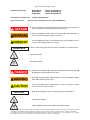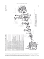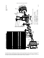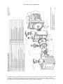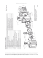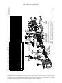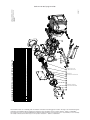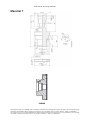
1
Seite 1 von 68 // page 1 of 68
Vakuumtechnik im System
Technology for Vacuum Systems
Instandsetzungsanleitung
Instructions for repair
Drehschieberpumpen / Rotary vane pumps
RE 2 / RZ 2 / RE 2.5 / RZ 2.5 / RE 5 / RZ 5 / RE 6 / RZ 6 /
RE 8 / RZ 8 / RE 9 / RZ 9 / RE 16 / RZ 16
Chemie-HYBRID-Pumpen / Chemistry-HYBRID-Pumps
RC 5 / RC 6
Vakuum-Messgerät / Vacuum gauge
VAP 5
Instandsetzungsanleitung: 999111 - 06 / Stand 26/01/2011
Gültig für
Drehschieberpumpen Typ RE 2, RZ 2, RE 2.5, RZ 2.5, RE 5, RZ 5, RE 6, RZ 6,
RE 8, RZ 8, RE 9, RZ 9, RE 16, RZ 16
HYBRID Pumpen Typ RC 5, RC 6
Vakuummessgerät VAP 5
Die Gültigkeit des pumpenspezifischen Zeichnungs- und Ersatzteileblatts ist anhand der Seriennummer der Pumpe vom Anwender zu prüfen.
Für Pumpen älterer oder neuerer Ausführung bitte das pumpenspezifische Zeichnungs- und Ersatzteileblatt unter Angabe von Pumpentyp, Seriennummer und Baujahr bei VACUUBRAND anfordern.
Instructions for repair: 999111 - 06 / version 26/01/2011
Valid for
Rotary vane pumps type RE 2, RZ 2, RE 2.5, RZ 2.5, RE 5, RZ 5, RE 6, RZ 6,
RE 8, RZ 8, RE 9, RZ 9, RE 16, RZ 16
HYBRID pumps type RC 5, RC 6
Vacuum gauge VAP 5
It is the users´ responsibility to check the validity of the pump specific drawing and spare parts list on
the basis of the serial number of the pump.
If the pump is older or newer please contact VACUUBRAND and order the pump specific drawing
and spare parts list stating the pump type, serial number and year of manufacture.
Das Dokument darf nur vollständig und unverändert verwendet und weitergegeben werden. Es liegt in der Verantwortung des
Anwenders, die Gültigkeit dieses Dokumentes bezüglich seines Produktes sicher zu stellen. BA-Nr.: 999111 // 26/01/2011
Documents are only to be used and distributed completely and unchanged. It is strictly the users´ responsibility to check carefully
the validity of this document with respect to his product. manual-no.: 999111 // 26/01/2011
Seite 2 von 68 // page 2 of 68
Technische Beratung
Gebiet Nord:
Gebiet Mitte:
Gebiet Süd:
Kundendienst und Service:
Telefon: 09342/808-209
After sales service:
Telefon: 09342/808-264
Telefon: 09342/808-263
Telefon: 09342/808-225
Contact your local dealer or call (++49) 9342/808-193.
➨ Gefahr! Unmittelbare Gefahr. Tod oder schwere Verletzungen sowie Schäden an Ausrüstung und Umgebung können eintreten.
☞ Warnung! Mögliche Gefahr. Schwere Verletzungen sowie Schäden an
Ausrüstung und Umgebung können eintreten.
•
HINWEIS
Vorsicht! Mögliche Gefahr. LeichteVerletzungen sowie Schäden an Ausrüstung und Umgebung können eintreten.
Hinweis. Missachtung der Hinweise kann zu Schäden am Produkt führen.
Heiße Oberfläche!
Netzstecker ziehen.
➨ Danger! Immediate danger. Death or severe injuries as well as damage
to equipment and environment can occur.
☞ Warning! Possible danger. Severe injuries as well as damage to equipment and environment can occur.
•
NOTICE
Caution! Possible danger. Slight injuries as well as damage to equipment and environment can occur.
Note. Disregarding of notes may cause damage to the product.
Caution! Hot surface!
Isolate equipment from mains before removing the cover.
Das Dokument darf nur vollständig und unverändert verwendet und weitergegeben werden. Es liegt in der Verantwortung des
Anwenders, die Gültigkeit dieses Dokumentes bezüglich seines Produktes sicher zu stellen. BA-Nr.: 999111 // 26/01/2011
Documents are only to be used and distributed completely and unchanged. It is strictly the users´ responsibility to check carefully
the validity of this document with respect to his product. manual-no.: 999111 // 26/01/2011
Seite 3 von 68 // page 3 of 68
Inhaltsverzeichnis / Contents
Unbedingt beachten! ................................................................................................. 4
Safety information! .................................................................................................... 6
Instandsetzung RE/Z 2 / 5 ......................................................................................... 8
Repair RE/Z 2 / 5 ...................................................................................................... 10
Instandsetzung RE/Z 2.5 / 6 .................................................................................... 14
Repair RE/Z 2.5 / 6 ................................................................................................... 17
Instandsetzung RE/Z 8 / 9 / 16 ................................................................................ 24
Repair RE/Z 8 / 9 / 16 ............................................................................................... 26
Instandsetzung RC 5 ............................................................................................... 32
Repair RC 5 .............................................................................................................. 34
Instandsetzung RC 6 ............................................................................................... 38
Repair RC 6 .............................................................................................................. 41
Abzieher für Kupplung ............................................................................................ 48
Puller for coupling ................................................................................................... 48
Einpressdorne ......................................................................................................... 49
Mandrels .................................................................................................................. 54
Vakuum-Messgerät VAP 5 ....................................................................................... 59
Vacuum gauge VAP 5 .............................................................................................. 61
Hinweise zur Einsendung ins Werk ....................................................................... 64
Unbedenklichkeitsbescheinigung ......................................................................... 65
Notes on return to the factory ................................................................................ 66
Health and safety clearance form .......................................................................... 67
Das Dokument darf nur vollständig und unverändert verwendet und weitergegeben werden. Es liegt in der Verantwortung des
Anwenders, die Gültigkeit dieses Dokumentes bezüglich seines Produktes sicher zu stellen. BA-Nr.: 999111 // 26/01/2011
Documents are only to be used and distributed completely and unchanged. It is strictly the users´ responsibility to check carefully
the validity of this document with respect to his product. manual-no.: 999111 // 26/01/2011
Seite 4 von 68 // page 4 of 68
Unbedingt beachten!
HINWEIS
Diese Anleitung zur Instandsetzung richtet sich an ausgebildetes Fachpersonal, das
aufgrund seiner fachlichen Qualifikation dazu in der Lage ist, die erforderlichen Arbeiten im Rahmen der gesetzlichen Bestimmungen (Arbeitssicherheit, Umweltschutz)
und Auflagen so auszuführen, dass die Funktion und die Sicherheit des Produkts
nicht beeinträchtigt werden. Insbesondere muss das Personal über die Arbeiten, die
möglicherweise in der Pumpe enthaltenen Stoffe und die damit verbundenen Risiken
informiert sein.
Betriebsanleitungen der Geräte lesen und insbesondere Sicherheitshinweise “Unbedingt beachten!“ sowie Hinweise zu “Bedienung und Betrieb“ beachten. Ggf.
Betriebsanleitung bei VACUUBRAND anfordern.
Verschleißteile müssen regelmäßig ausgetauscht werden. Bei normaler Beanspruchung kann von einer Lebensdauer von Membranen und Ventilen größer 10000
Betriebsstunden ausgegangen werden. Motorlager haben eine typische Lebensdauer von 40000 Betriebsstunden. Motorkondensatoren weisen abhängig von den Einsatzbedingungen, wie Umgebungstemperatur, Luftfeuchtigkeit und Motorlast, eine typische Lebensdauer von 10000 bis 40000 Betriebsstunden auf.
• Kondensatoren müssen regelmäßig geprüft (Kapazität messen, Betriebsstunden
abschätzen) und rechtzeitig ausgetauscht werden. Ein überalterter Kondensator
kann heiß werden, ggf. schmelzen. Selten kann es auch zu einer Stichflamme
kommen, die eine Gefahr für Personal und Umgebung darstellen kann. Der Austausch der Kondensatoren muss von einer Elektrofachkraft durchgeführt werden.
HINWEIS
HINWEIS
Wurden gefährliche oder korrosive Gase gepumpt?
☞ Achtung: Durch den Betrieb können die Geräte mit gesundheitsschädlichen oder
anderweitig gefährlichen Stoffen verunreinigt sein, ggf. vor Kontakt dekontaminieren bzw. reinigen.
- Vorsichtsmaßnahmen (z. B. Schutzkleidung, Schutzhandschuhe, Sicherheitsbrille)
treffen, um Einatmen und Hautkontakt zu vermeiden.
Vor Aufnahme der Wartungsarbeiten prüfen, ob das benötigte Werkzeug und die
erforderlichen auszutauschenden Originalteile zur Verfügung stehen.
- Anhand der Explosionszeichnung, Ersatzteillisten sowie der elektrischen Schaltbilder die auszuführenden Arbeiten zunächst gedanklich bezüglich Ausführbarkeit, Arbeitssicherheit sowie möglicher Auswirkungen auf die Sicherheit und Funktion der Pumpe prüfen.
➨ Vor jedem Eingriff Geräte vom Netz trennen und anschließend zwei Minuten warten, bis sich die Kondensatoren entladen haben.
➨ Pumpe belüften und von der Apparatur trennen. Die Pumpe abkühlen lassen, ggf.
Kondensat entleeren.
☞ Pumpe niemals in geöffnetem Zustand betreiben. Sicherstellen, dass die Pumpe
keinesfalls im geöffneten Zustand unbeabsichtigt anlaufen kann. Defekte oder
beschädigte Pumpen nicht weiter betreiben.
Eingriffe am Gerät nur durch sachkundige Personen. Reparatur von eingesandten
Geräten ist nur gemäß den gesetzlichen Bestimmungen (Arbeitssicherheit, Umweltschutz) und Auflagen möglich, siehe Kapitel ”Hinweise zur Einsendung ins Werk”.
Das Dokument darf nur vollständig und unverändert verwendet und weitergegeben werden. Es liegt in der Verantwortung des
Anwenders, die Gültigkeit dieses Dokumentes bezüglich seines Produktes sicher zu stellen. BA-Nr.: 999111 // 26/01/2011
Documents are only to be used and distributed completely and unchanged. It is strictly the users´ responsibility to check carefully
the validity of this document with respect to his product. manual-no.: 999111 // 26/01/2011
Seite 5 von 68 // page 5 of 68
•
Nur Originalteile und Originalzubehör verwenden. Bei der Verwendung von
Komponenten anderer Hersteller kann die Funktion bzw. die Sicherheit des Geräts sowie die elektromagnetische Verträglichkeit eingeschränkt sein.
Die Gültigkeit des CE-Kennzeichens bzw. die Zertifizierung für USA/Kanada (siehe Typenschild) kann erlöschen, wenn keine Originalteile verwendet werden.
-
Beschädigte Komponenten müssen in jedem Fall ausgetauscht werden.
Nach der Instandsetzung Pumpe auf Sicherheit und Funktion prüfen.
Die Prüfung der elektrischen Sicherheit (Schutzleiterwiderstand, Isolationswiderstand
und Hochspannungsprüfung) muss gemäß IEC 61010 und nationaler Vorschriften
erfolgen.
HINWEIS
-
Bei auftretenden Problemen ggf. Pumpe ins Werk zur Überprüfung oder Reparatur einsenden.
Chemikalien unter Berücksichtigung eventueller Verunreinigungen durch abgepumpte
Substanzen entsprechend den einschlägigen Vorschriften entsorgen.
Reparatur von eingesandten Vakuumpumpen, Bauteilen oder Messgeräten ist nur
gemäß den gesetzlichen Bestimmungen (Arbeitssicherheit, Umweltschutz) und Auflagen möglich (siehe Kapitel “Hinweise zur Einsendung ins Werk“).
Verschrottung und Entsorgung:
Das gesteigerte Umweltbewusstsein und die verschärften Vorschriften machen eine
geordnete Verschrottung und Entsorgung eines nicht mehr gebrauchs- und reparaturfähigen Produkts zwingend erforderlich.
- Sie können uns ermächtigen, zu Ihren Lasten das Produkt geordnet zu entsorgen.
Das Dokument darf nur vollständig und unverändert verwendet und weitergegeben werden. Es liegt in der Verantwortung des
Anwenders, die Gültigkeit dieses Dokumentes bezüglich seines Produktes sicher zu stellen. BA-Nr.: 999111 // 26/01/2011
Documents are only to be used and distributed completely and unchanged. It is strictly the users´ responsibility to check carefully
the validity of this document with respect to his product. manual-no.: 999111 // 26/01/2011
Seite 6 von 68 // page 6 of 68
Safety information!
NOTICE
Ensure that repair is done only by an appropriately trained and supervised technician. Obey local and national safety requirements. Ensure that the technician is familiar with the safety procedures which relate to the products processed by the pumping
system. Ensure that the pump is decontaminated before repair and that you take
adequate precautions to protect people from the effects of hazardous substances if
contamination has occurred.
Read the instructions for use for the equipment carefully, especially sections “Safety
informations“ and “Use and operation“. If necessary order ”Instructions for use” from
VACUUBRAND.
Wear parts have to be replaced regularly. In case of normal wear the lifetime of the
diaphragms and valves is > 10000 operating hours. Bearings have a typical durability of
40000 h. Motor capacitors have a typical durability in the range of 10000 to 40000 h
depending strongly on the operation conditions like ambient temperature, humidity or
load.
• Check every capacitor regularly by measuring its capacity and estimating its operation time. Exchange old capacitors early enough to prevent a failure. If an
overaged motor capacitor fails it might get hot and even melt and may cause a
flame to form which could be dangerous for persons and equipment in the
vicinity. The capacitors have to be replaced by an electrician.
NOTICE
If hazardous or corrosive substances have been pumped:
- The device will be contaminated with the process chemicals which have been
pumps during operation. Ensure that the pump is decontaminated before maintenance.
- Take adequate precautions to protect people from the effects of dangerous substances. Wear appropriate safety-clothing, do not inhale and avoid contact with
skin.
NOTICE
Before starting repair check that the required parts are available and of the correct
type before you start your work.
- Check the operating sequence mentally using exploded view drawings, spare
parts lists and circuit diagram on feasibility, safety requirements and consequences
on safety and function of the equipment.
-
Isolate equipment from mains and wait two minutes before starting maintenance to allow the capacitors to discharge.
-
Vent the pump, isolate the pump and other components from the vacuum system.
Allow sufficient cooling of the pump. Drain condensate, if applicable.
☞ Ensure that the pump cannot be operated accidentally. Never operate the
pump if covers or other parts of the pump are disassembled. Never operate
a defective or damaged pump.
Ensure that maintenance is done only by suitably trained and supervised technicians. Ensure that the maintenance technician is familiar with the safety procedures
which relate to the products processed by the pumping system.
In order to comply with law (occupational, health and safety regulations, safety at work
law and regulations for environmental protection) vacuum pumps, components and
measuring instruments returned to the manufacturer can be repaired only when certain procedures (see section ”Notes on return to the factory”) are followed.
Das Dokument darf nur vollständig und unverändert verwendet und weitergegeben werden. Es liegt in der Verantwortung des
Anwenders, die Gültigkeit dieses Dokumentes bezüglich seines Produktes sicher zu stellen. BA-Nr.: 999111 // 26/01/2011
Documents are only to be used and distributed completely and unchanged. It is strictly the users´ responsibility to check carefully
the validity of this document with respect to his product. manual-no.: 999111 // 26/01/2011
Seite 7 von 68 // page 7 of 68
➨ Use only genuine spare parts and accessories. Otherwise safety and performance of the equipment as well as the electromagnetic compatibility of the equipment might be reduced.
Possibly the CE mark or the C/US conformity becomes void if not using genuine
spare parts.
-
Replace damaged parts in any case.
Check operability and safety after repair.
Check the electrical safety (protective conductor resistance, insulating resistance,
high voltage test) according to IEC 61010 and national regulations.
NOTICE
-
In case of problems return the pump to the factory for inspection or repair if necessary.
Obey regulations when disposing of solvents and chemicals.
In order to comply with law (occupational, health and safety regulations, safety at
work law and regulations for environmental protection) vacuum pumps, components
and measuring instruments returned to the manufacturer can be repaired only when
certain procedures (see section “Notes on return to the factory“) are followed.
Scrapping and waste disposal
Dispose of the pump and any components removed from it safely in accordance with
all local and national safety and environmental requirements.
Particular care must be taken with components and waste oil which have been contaminated with dangerous substances from the process.
- You may authorize us to dispose the equipment at your expense.
Das Dokument darf nur vollständig und unverändert verwendet und weitergegeben werden. Es liegt in der Verantwortung des
Anwenders, die Gültigkeit dieses Dokumentes bezüglich seines Produktes sicher zu stellen. BA-Nr.: 999111 // 26/01/2011
Documents are only to be used and distributed completely and unchanged. It is strictly the users´ responsibility to check carefully
the validity of this document with respect to his product. manual-no.: 999111 // 26/01/2011
Seite 8 von 68 // page 8 of 68
Instandsetzung RE/Z 2 / 5
Vor Beginn der Arbeiten Pumpe von der Apparatur trennen und Netzstecker ziehen,
Pumpe abkühlen lassen. Sicherstellen, dass die Pumpe keinesfalls im geöffneten
Zustand unbeabsichtigt anlaufen kann.
Vor jedem Eingriff nach Trennen der Geräte vom Netz zwei Minuten warten, bis sich
die Kondensatoren entladen haben.
Reinigung der Komponenten
☞ Altöl und Lösemittel unter Berücksichtigung eventueller Verunreinigungen durch abgepumpte Chemikalien entsprechend den einschlägigen Vorschriften entsorgen.
☞ Beschädigung an Lauf- und Dichtflächen vermeiden!
☞ Dichtringe: Sauberes Öl und faserfreien Lappen verwenden, ggf. Dichtringe erneuern.
☞ Geräuschdämpfungsdüse prüfen, ggf. reinigen (Draht von 0.2 mm oder Pressluft verwenden).
☞ Alle übrigen Teile: Waschbenzin oder technisches Lösemittel verwenden, Verwendungsvorschriften
beachten.
☞ Nach der Reinigung alle Teile mit Pressluft trocknen.
Werkzeuge
Innensechskant SW 3/4/5
Gabelschlüssel SW 14
Kreuzschlitzschraubendreher Gr. 1 und 2
Schraubendreher mit Flachklinge Gr. 2
Schraubendreher für Stehbolzen Gr. M4 und M5
Demontage der Pumpe
-
Öl ablassen (siehe “Ölwechsel“ in Betriebsanleitung).
Pumpe auf die Stirnfläche des Ölkastens (auf Typenschild) stellen.
Schrauben an der Lüfterhaube lösen und Lüfterhaube abnehmen.
Motorbefestigungsschrauben lösen und Motor aus dem Gehäuse heben. Läufer aus dem Motorpaket
entfernen..
Austausch der Kupplung
- Kupplung auf Einlaufspuren prüfen, ”Fingernagelprobe” durchführen. Falls Vertiefungen festzustellen
sind, Kupplung austauschen. Kupplung nicht polieren, da die dünne gehärtete Schicht abgetragen
werden könnte und ”falsche” Mikroriefen die Dichtigkeit beeinflussen.
- Kupplung abziehen. Motorwelle mit neuem Toleranzring bestücken. Toleranzring trocken, öl- und fettfrei montieren.
- Die Kupplung muss mit einer geeigneten Vorrichtung eingepresst werden. Dabei muss die Motorwelle
auf der Lüfterseite durch die mittige Bohrung in der Lüfterhaube abgestützt werden. Ohne Abstützung
werden die Motorlager beschädigt. Beim Aufpressen der Kupplung nicht auf das Lüfterrad drücken.
Demontage des Aggregats
- Schutzschild mit O-Ring entnehmen.
- Schrauben an der Wechselhülse lösen und Wechselhülse abnehmen.
Das Dokument darf nur vollständig und unverändert verwendet und weitergegeben werden. Es liegt in der Verantwortung des
Anwenders, die Gültigkeit dieses Dokumentes bezüglich seines Produktes sicher zu stellen. BA-Nr.: 999111 // 26/01/2011
Documents are only to be used and distributed completely and unchanged. It is strictly the users´ responsibility to check carefully
the validity of this document with respect to his product. manual-no.: 999111 // 26/01/2011
Seite 9 von 68 // page 9 of 68
-
Vier Innensechskantschrauben an der Rückseite des Pumpengehäuses lösen.
Gehäuse mit Aggregat aus dem Ölkasten herausnehmen und auf das Gehäuse stellen.
Aggregatbefestigungsschrauben lösen.
Lagerdeckel abnehmen.
Rotor herausziehen.
Ölpumpenrotor mit Schiebern abnehmen.
Vorstufenstator mit Ölabscheider abnehmen.
Zwischenlager, Hochstufenstator, Hochstufenrotor und Lagerschild abnehmen (nur RZ 2/5).
Teile reinigen.
- Durchgangsbohrungen der Ölkanäle überprüfen, ggf. reinigen.
- Alle Dichtringe auf Sprödigkeit und Risse überprüfen, ggf. erneuern.
- Geräuschdämpfungsdüse prüfen, ggf. reinigen.
-
Verschlussschraube der Rückhaltekugel am Lagerdeckel lösen. Rückhaltekugel mit Feder entnehmen und überprüfen, ggf. erneuern.
Ölabscheideroberteil und -unterteil abschrauben.
Ventilkappe, Feder und Ventilsitz überprüfen. Ventilkappe und Feder ggf. erneuern.
Austausch der Kupplungsbuchsen
- Kupplungsbuchsen in den Rotoren überprüfen, ggf. erneuern.
- Kupplungsbuchsen entfernen (z. B. mit einer Holzschraube) und neue Kupplungsbuchsen bündig
einpressen.
Austausch der Wellendichtungen
- Wellendichtung im Lagerschild, Zwischenlager und Lagerdeckel überprüfen und ggf. austauschen.
- Wellendichtung mit geeignetem Dorn (Spezialwerkzeug, siehe hinten) auspressen.
- Neuen Wellendichtring versetzt einpressen.
- Wellendichtringe sollten nur mit einem speziellen Einpressdorn montiert werden (siehe Tabelle und
Zeichnungen). Nur auf den Aussenring des Wellendichtrings drücken. Beim Einpressen von Radialwellendichtringen mittels eines Einpressdorns darauf achten, dass der Dorn auf der Unterseite des
Dichtrings ungehindert austreten kann.
Montage der Pumpe
-
-
Montage in umgekehrter Reihenfolge wie Demontage.
Alle Gleitflächen mit Pumpenöl benetzen.
Neue O-Ringe einsetzen, für besseren Sitz ggf. etwas dehnen.
Ölpumpenrotor mit abgerundeter Seite voran in den Lagerdeckel legen.
Vor der Montage der Ölpumpenschieber Ölpumpe mit Vakuumpumpenöl füllen.
Ölpumpenabdeckscheibe so montieren, dass die innenliegende Halbrundnut nach rechts zur Rückhaltekugel zeigt.
Komplett montiertes Aggregat in den Ölkasten setzen und mit dem Gehäuse verschrauben.
Wechselhülse montieren.
Raum vor der Wechselhülse im Gehäuse zur Hälfte mit Pumpenöl füllen.
Schutzschild mit O-Ring einsetzen.
Kupplung leicht mit Vakuumfett fetten.
Wicklungspaket auf das Gehäuse aufsetzen, dann Motorläufer mit Kupplung aufsetzen und durch das
Eigengewicht in die Wechselhülse gleiten lassen. Alternativ kann der Motor auch komplett mit Kupplung montiert werden, ggf. durch Drehen am Lüfter Kupplungsstifte geeignet positionieren.
Motor mit Gehäuse verschrauben.
Gängigkeit des Aggregats durch Drehen des Lüfterrads prüfen.
Lüfterhaube festschrauben.
Pumpenöl einfüllen (siehe ”Ölwechsel” in Betriebsanleitung ).
-
Pumpe mit offenem Gasballastventil und geschlossenem Saugstutzen ca. 1h laufen lassen.
-
Das Dokument darf nur vollständig und unverändert verwendet und weitergegeben werden. Es liegt in der Verantwortung des
Anwenders, die Gültigkeit dieses Dokumentes bezüglich seines Produktes sicher zu stellen. BA-Nr.: 999111 // 26/01/2011
Documents are only to be used and distributed completely and unchanged. It is strictly the users´ responsibility to check carefully
the validity of this document with respect to his product. manual-no.: 999111 // 26/01/2011
Seite 10 von 68 // page 10 of 68
Repair RE/Z 2 / 5
Before starting repair, isolate the pump and other components from the vacuum system and the electrical supply so that they cannot be operated accidentally. Allow the
pump to cool, so that it is at safe temperature for skin contact.
Before starting maintenance, wait two minutes after isolating the equipment from
mains to allow the capacitors to discharge.
Cleaning of components
☞ Observe applicable regulations when disposing of used oil and solvents which may be contaminated
by chemicals.
☞ Avoid damage of bearing and sealing surfaces!
☞
☞
☞
☞
Seal rings: Use only clean oil and lint-free cloths. Replace seals rings if necessary.
Silencer nozzle: Clean with length of thin wire (0.2 mm) and compressed air.
All other components: Clean with petroleum or suitable solvent. Follow manufacturer`s instruction.
After cleaning, dry all components with compressed air.
Tools
Hex key SW 3/4/5
Open-ended wrench SW 14
Phillips screw driver size 2 and 3
Flat-bladed screw driver size 2
Screw driver for stud bolt size M4 and M5
Disassembly of the pump
-
Drain oil (see ”Oil change” in the instructions for use).
Position pump so that it rests on the face of the oil reservoir (on rating plate).
Unscrew screws at the fan cover and remove fan cover.
Unscrew screws at the motor and remove pump from the housing.
Changing the coupling
- If the coupling is visibly worn, check for grooves (e. g. by feeling with finger nails). In case of depressions, replace coupling. Do not polish coupling as thin hardened layer may be damaged and microscopic grooves will cause oil leaks.
- Remove coupling. Put on new spring ring on the motor shaft. Assemble the spring ring dry, oil and
grease free.
- Press in new coupling by using an appropriate device. Make sure that the motor shaft is supported
(through centre hole in fan cover), otherwise the ball bearing will be damaged. When pressing in the
coupling, do not apply pressure to the impeller.
Disassembling the pump unit
- Remove cover plate together with O-ring.
- Unscrew screws at the removable sleeve and remove sleeve.
- Unscrew screws at the rear side of the pump housing.
- Remove housing with pump unit from the oil reservoir and position it on the housing.
- Unscrew pump unit securing screws.
- Remove bearing cover.
- Remove rotor.
Das Dokument darf nur vollständig und unverändert verwendet und weitergegeben werden. Es liegt in der Verantwortung des
Anwenders, die Gültigkeit dieses Dokumentes bezüglich seines Produktes sicher zu stellen. BA-Nr.: 999111 // 26/01/2011
Documents are only to be used and distributed completely and unchanged. It is strictly the users´ responsibility to check carefully
the validity of this document with respect to his product. manual-no.: 999111 // 26/01/2011
Seite 11 von 68 // page 11 of 68
-
Remove oil pump rotor with oil pump vanes.
Remove low vacuum stage stator with oil separator.
Remove intermediate bearing plate, high vacuum stage stator, high vacuum rotor and bearing plate
(only RZ 2/5).
Cleaning parts
- Check through bores of the oil lines, clean if necessary.
- Check all seal rings for conglutination and cracks, replace if necessary.
- Check silencer nozzle, clean if necessary.
-
Remove threaded plug of the detent ball in the bearing cover. Remove and check detent ball with
spring, replace if necessary.
Remove oil separator upper and lower part.
Check valve cap, spring and valve seat. Replace valve cap and spring if necessary.
Changing the coupling bushes
- Check coupling bushes in the rotors, replace if necessary.
- Remove bushes (e. g. by using a woodscrew). Press in flush new coupling bushes.
Changing the shaft seals
- Check shaft seals in the bearing plate, intermediate bearing plate and bearing cover and replace if
necessary.
- Remove shaft seal from housing by using an appropriate mandrel (special tool, see below).
- Press in new shaft seal, make sure that it remains level to bore.
- Assemble shaft seals only by using a special mandrel (see table and drawings). Apply pressure only to
the outer ring. Take into consideration that the mandrel will pass under the seal and ensure that no
other part can be damaged.
Assembly of the pump
-
-
Assemble pump in reverse order of disassembling.
Lubricate all wear faces with pump oil.
Install new O-rings, stretch slightly to seat if necessary.
Place oil pump rotor with rounded face first in bearing cover.
Fill in vacuum oil into the oil pump before assembling oil pump vanes.
Position oil pump cover so that the internal half-round groove is directed right to the detent ball.
Position the complete assembled pump unit in the oil reservoir and screw together with housing.
Assemble removable sleeve.
Fill half of the chamber in front of the removable sleeve with pump oil.
Position shielding with O-ring.
Lubricate the coupling using vacuum grease.
Attach the winding on the top of the housing then place on top the rotor with coupling. The coupling
glides through the removable sleeve. Alternatively assemble the motor complete with coupling, turn
the fan to position the coupling pins suitably if necessary.
Screw motor to housing.
Check operability of the pump unit by turning the impeller.
Assemble fan cover.
Fill in pump oil (see ”Oil change” in the instruction for use).
-
Allow the pump to run with gas ballast valve open and inlet closed for approx. 1 h.
Das Dokument darf nur vollständig und unverändert verwendet und weitergegeben werden. Es liegt in der Verantwortung des
Anwenders, die Gültigkeit dieses Dokumentes bezüglich seines Produktes sicher zu stellen. BA-Nr.: 999111 // 26/01/2011
Documents are only to be used and distributed completely and unchanged. It is strictly the users´ responsibility to check carefully
the validity of this document with respect to his product. manual-no.: 999111 // 26/01/2011
Seite 12 von 68 // page 12 of 68
Das Dokument darf nur vollständig und unverändert verwendet und weitergegeben werden. Es liegt in der Verantwortung des
Anwenders, die Gültigkeit dieses Dokumentes bezüglich seines Produktes sicher zu stellen. BA-Nr.: 999111 // 26/01/2011
Documents are only to be used and distributed completely and unchanged. It is strictly the users´ responsibility to check carefully
the validity of this document with respect to his product. manual-no.: 999111 // 26/01/2011
Seite 13 von 68 // page 13 of 68
Das Dokument darf nur vollständig und unverändert verwendet und weitergegeben werden. Es liegt in der Verantwortung des
Anwenders, die Gültigkeit dieses Dokumentes bezüglich seines Produktes sicher zu stellen. BA-Nr.: 999111 // 26/01/2011
Documents are only to be used and distributed completely and unchanged. It is strictly the users´ responsibility to check carefully
the validity of this document with respect to his product. manual-no.: 999111 // 26/01/2011
Seite 14 von 68 // page 14 of 68
Instandsetzung RE/Z 2.5 / 6
Vor Beginn der Arbeiten Pumpe von der Apparatur trennen und Netzstecker ziehen,
Pumpe abkühlen lassen. Sicherstellen, dass die Pumpe keinesfalls im geöffneten
Zustand unbeabsichtigt anlaufen kann.
Vor jedem Eingriff nach Trennen der Geräte vom Netz zwei Minuten warten, bis sich
die Kondensatoren entladen haben.
Reinigung der Komponenten
☞ Altöl und Lösemittel unter Berücksichtigung eventueller Verunreinigungen durch abgepumpte Chemikalien entsprechend den einschlägigen Vorschriften entsorgen.
☞ Beschädigung an Lauf- und Dichtflächen vermeiden!
☞ Dichtringe: Sauberes Öl und faserfreien Lappen verwenden, ggf. Dichtringe erneuern.
☞ Geräuschdämpfungsdüse prüfen, ggf. reinigen (Draht von 0.2 mm oder Pressluft verwenden).
☞ Alle übrigen Teile: Waschbenzin oder technisches Lösemittel verwenden, Verwendungsvorschriften
beachten.
☞ Nach der Reinigung alle Teile mit Pressluft trocknen.
Werkzeuge
Innensechskant SW 3/4/5
Gabelschlüssel SW 14
Kreuzschlitzschraubendreher Gr. 1 und 2
Schraubendreher mit Flachklinge Gr. 2
Schraubendreher für Stehbolzen Gr. M4 und M5
Austausch der Wechselhülse
☞ Bei Ölundichtigkeit der Pumpe (Öl tropft unten aus dem Gehäuse) ist es oft ausreichend nur die
Wechselhülse zu tauschen. Das Pumpenöl muss dazu nicht abgelassen werden.
- Auspufffilter demontieren, falls vorhanden.
- Auslass der Pumpe verschließen.
- Pumpe auf die Stirnfläche des Ölkastens (auf Typenschild) stellen.
- Abdeckung des Saugfilzes demontieren und Saugfilz überprüfen.
- Schrauben an der Lüfterhaube lösen und Lüfterhaube abnehmen.
- Motorbefestigungsschrauben lösen und Motor aus dem Gehäuse heben. Läufer aus dem Motorpaket
entfernen.
- Kupplung auf Einlaufspuren prüfen, ”Fingernagelprobe” durchführen. Falls Vertiefungen festzustellen
sind, Kupplung austauschen. Kupplung nicht polieren, da die dünne gehärtete Schicht abgetragen
werden könnte und ”falsche” Mikroriefen die Dichtigkeit beeinflussen. Kreuzkupplung entfernen.
- Schutzwand herausnehmen.
- Schrauben an der Wechselhülse lösen, Wechselhülse abnehmen und neue montieren.
- Kreuzkupplung in das Aggregat einsetzen.
- Vakuumpumpenöl in den Raum vor der Wechselhülse füllen.
- Schutzwand mit O-Ring einsetzen.
- Wicklungspaket auf das Gehäuse aufsetzen, dann Motorläufer aufsetzen und durch das Eigengewicht in die Wechselhülse und die Kupplung gleiten lassen.
- Motor mit Gehäuse verschrauben.
- Gängigkeit des Aggregats durch Drehen des Lüfterrads prüfen.
- Lüfterhaube festschrauben.
- Saugfilz unten im Gehäuse erneuern.
-
Pumpe mit offenem Gasballastventil und geschlossenem Saugstutzen ca. 1h laufen lassen.
Das Dokument darf nur vollständig und unverändert verwendet und weitergegeben werden. Es liegt in der Verantwortung des
Anwenders, die Gültigkeit dieses Dokumentes bezüglich seines Produktes sicher zu stellen. BA-Nr.: 999111 // 26/01/2011
Documents are only to be used and distributed completely and unchanged. It is strictly the users´ responsibility to check carefully
the validity of this document with respect to his product. manual-no.: 999111 // 26/01/2011
Seite 15 von 68 // page 15 of 68
Demontage der Pumpe
-
Öl ablassen (siehe “Ölwechsel“ in Betriebsanleitung).
Auspufffilter demontieren, falls vorhanden.
Pumpe auf die Stirnfläche des Ölkastens (auf Typenschild) stellen.
Schrauben an der Lüfterhaube lösen und Lüfterhaube abnehmen.
Motorbefestigungsschrauben lösen und Motor aus dem Gehäuse heben. Läufer aus dem Motorpaket
entfernen.
Kupplung auf Einlaufspuren prüfen, ”Fingernagelprobe” durchführen. Falls Vertiefungen festzustellen
sind, Kupplung austauschen. Kupplung nicht polieren, da die dünne gehärtete Schicht abgetragen
werden könnte und ”falsche” Mikroriefen die Dichtigkeit beeinflussen. Kreuzkupplung entfernen.
Demontage des Aggregats
- Schutzwand mit O-Ring entnehmen.
- Schrauben an der Wechselhülse lösen, Wechselhülse abnehmen.
- Vier Innensechskantschrauben an der Rückseite des Pumpengehäuses lösen.
- Gehäuse mit Aggregat aus dem Ölkasten herausnehmen und auf das Gehäuse stellen.
- Abdeckscheibe demontieren.
- Verschlussschraube der Rückhaltekugel am Lagerdeckel lösen. Rückhaltekugel mit Feder entnehmen und überprüfen, ggf. erneuern.
- Geräuschdämpfungsdüse herausdrehen. Achtung: Die Düse ist mit Sicherungsklebstoff Omnifit® 50M
eingeklebt. Geräuschdämpfungsdüse auf Durchgängigkeit prüfen, ggf. reinigen.
- Zwei Aggregatschrauben lösen und Lagerdeckel abnehmen.
- Ölpumpenrotor mit Schiebern herausdrücken.
- Schieber überprüfen und ggf. erneuern.
- Vorstufenstator mit Ölabscheider abnehmen. Ölbohrung (Durchmesser 0,8 mm) auf Durchgängigkeit
prüfen.
- Auslassventil demontieren. Ventilkappe, Feder und Ventilsitz überprüfen. Ventilkappe und Feder ggf.
erneuern.
- Vorstufenrotor mit Schiebern abnehmen. Kreuzkupplung und Drehschieber demontieren. Schieber
überprüfen und ggf. erneuern.
- Nur Pumpentyp RZ: Zwischenlager, Hochstufenstator, Hochstufenrotor mit Kreuzkupplung und Lagerschild abnehmen.
Austausch der Wellendichtungen
- Wellendichtung im Lagerschild und Lagerdeckel überprüfen und ggf. austauschen.
- Wellendichtung auspressen, Oberflächen nicht beschädigen.
- Neuen Wellendichtring einpressen.
☞ Wellendichtringe sollten nur mit einem speziellen Einpressdorn montiert werden (siehe Tabelle und
Zeichnungen). Nur auf den Aussenring des Wellendichtrings drücken. Beim Einpressen von Radialwellendichtringen mittels eines Einpressdorns darauf achten, dass der Dorn auf der Unterseite des
Dichtrings ungehindert austreten kann.
Das Dokument darf nur vollständig und unverändert verwendet und weitergegeben werden. Es liegt in der Verantwortung des
Anwenders, die Gültigkeit dieses Dokumentes bezüglich seines Produktes sicher zu stellen. BA-Nr.: 999111 // 26/01/2011
Documents are only to be used and distributed completely and unchanged. It is strictly the users´ responsibility to check carefully
the validity of this document with respect to his product. manual-no.: 999111 // 26/01/2011
Seite 16 von 68 // page 16 of 68
Montage der Pumpe
☞ Alle Gleitflächen mit Pumpenöl benetzen.
☞ Neue O-Ringe einsetzen, für besseren Sitz ggf. etwas dehnen.
-
-
Wechselhülse montieren.
Schutzwand mit O-Ring einsetzen.
Wicklungspaket auf das Gehäuse aufsetzen, dann Motorläufer aufsetzen und durch das Eigengewicht in die Wechselhülse gleiten lassen.
Motor mit Gehäuse verschrauben.
Lüfterhaube festschrauben.
Pumpe auf die Lüfterhaube stellen.
O-Ring in Gehäuse legen.
Lagerschild montieren.
Kreuzkupplung einsetzen.
Raum zwischen Kreuzkupplung und Rotor halb mit Pumpenöl füllen.
Rotor mit Schiebern einsetzen.
Hochstufenstator montieren.
O-Ring einlegen.
Nur Pumpen Typ RZ: Zwischenlager montieren. O-Ring einlegen. Rotor mit Schiebern einsetzen.
Vorstufenstator montieren. O-Ring einsetzen.
Lagerdeckel montieren.
Aggregat mit den beiden Aggregatschrauben mit Usit-Ringen verschrauben. Auf gleichmäßigen Anzug der Schrauben achten.
Ölpumpe einsetzen. Schieber einlegen, Einbaulage beachten.
Ölpumpenschöpfraum mit Öl befüllen.
Abdeckscheibe montieren.
RHV-Kugel mit Feder montieren.
Komplett montiertes Aggregat in den Ölkasten setzen und mit dem Gehäuse verschrauben.
Ggf. Saugfilz unten im Gehäuse erneuern.
-
Pumpenöl einfüllen (siehe ”Ölwechsel” in Betriebsanleitung).
Pumpe mit offenem Gasballastventil und geschlossenem Saugstutzen ca. 1h laufen lassen.
-
Das Dokument darf nur vollständig und unverändert verwendet und weitergegeben werden. Es liegt in der Verantwortung des
Anwenders, die Gültigkeit dieses Dokumentes bezüglich seines Produktes sicher zu stellen. BA-Nr.: 999111 // 26/01/2011
Documents are only to be used and distributed completely and unchanged. It is strictly the users´ responsibility to check carefully
the validity of this document with respect to his product. manual-no.: 999111 // 26/01/2011
Seite 17 von 68 // page 17 of 68
Repair RE/Z 2.5 / 6
Before starting repair, isolate the pump and other components from the vacuum system and the electrical supply so that they cannot be operated accidentally. Allow the
pump to cool, so that it is at safe temperature for skin contact.
Before starting maintenance, wait two minutes after isolating the equipment from
mains to allow the capacitors to discharge.
Cleaning of components
☞ Observe applicable regulations when disposing of used oil and solvents which may be contaminated
by chemicals.
☞ Avoid damage of bearing and sealing surfaces!
☞ Seal rings: Use only clean oil and lint-free cloths. Replace seals rings if necessary.
☞ Silencer nozzle: Clean with length of thin wire (0.2 mm) and compressed air.
☞ All other components: Clean with petroleum or suitable solvent. Follow manufacturer`s instruction.
☞ After cleaning, dry all components with compressed air.
Tools
Hex key SW 3/4/5
Open-ended wrench SW 14
Phillips screw driver size 2 and 3
Flat-bladed screw driver size 2
Screw driver for stud bolt size M4 and M5
Replacing the removable sleeve
☞ In case of oil leaks of the pump (oil drops out at the lower side of the pump housing) it is often sufficient
to replace only the removable sleeve. Therefore it is not necessary to drain the pump oil.
- Disassemble oil mist filter if applicable.
- Close outlet of the pump.
- Position pump so that it rests on the face of the oil reservoir (on rating plate).
- Remove cover of the felt and check felt .
- Disassemble screws at the fan cover and remove fan cover.
- Disassemble screws at the motor and remove motor from the housing. Remove armature from motor.
- If the coupling is visibly worn, check for grooves (e. g. by feeling with finger nails). In case of depressions, replace coupling. Do not polish coupling as thin hardened layer may be damaged and microscopic grooves will cause oil leaks. Remove cross coupling.
- Remove the shielding.
- Disassemble screws at the removable sleeve, remove removable sleeve and assemble a new one.
- Position cross coupling in the aggregate.
- Fill in oil in the chamber in front of the removable sleeve.
- Position shielding with O ring.
- Attach the winding on the top of the housing. The motor armature glides through the removable sleeve
into the coupling.
- Assemble motor to housing.
- Check mobility of the aggregate by turning the impeller.
- Assemble fan cover.
- Replace felt at the lower side of the pump housing.
-
Let the pump run with gas ballast valve open and inlet closed for approximately 1 hour.
Das Dokument darf nur vollständig und unverändert verwendet und weitergegeben werden. Es liegt in der Verantwortung des
Anwenders, die Gültigkeit dieses Dokumentes bezüglich seines Produktes sicher zu stellen. BA-Nr.: 999111 // 26/01/2011
Documents are only to be used and distributed completely and unchanged. It is strictly the users´ responsibility to check carefully
the validity of this document with respect to his product. manual-no.: 999111 // 26/01/2011
Seite 18 von 68 // page 18 of 68
Disassembly of the pump
-
Drain oil (see ”Oil change” in the instructions for use).
Disassemble oil mist filter if applicable.
Position pump so that it rests on the face of the oil reservoir (on rating plate).
Unscrew screws at the fan cover and remove fan cover.
Unscrew screws at the motor and remove motor from the housing. Remove armature from the motor.
If the coupling is visibly worn, check for grooves (e. g. by feeling with finger nails). In case of depressions, replace coupling. Do not polish coupling as thin hardened layer may be damaged and microscopic grooves will cause oil leaks. Remove cross coupling.
Disassembling the pump unit
- Remove shielding together with O-ring.
- Unscrew screws at the removable sleeve and remove sleeve.
- Unscrew screws at the rear side of the pump housing.
- Remove housing with pump unit from the oil reservoir and position it on the housing.
- Remove bearing cover.
- Remove threaded plug of the detent ball in the bearing cover. Remove and check detent ball with
spring, replace if necessary.
- Disassemble silencer nozzle. Attention: The nozzle is secured with adhesive Omnifit® 50M. Check
silencer nozzle for passage and clean if necessary.
- Remove two aggregate screws and remove bearing cover.
- Remove oil pump rotor with oil pump vanes.
- Check vanes and replace if necessary.
- Remove low vacuum stage stator with oil separator. Check oil bores (diameter 0,8 mm) for passage.
- Disassemble outlet valve. Check valve cap, spring and valve seat. Replace valve cap and spring if
necessary.
- Remove low vacuum stage rotor with vanes. Disassemble cross coupling and rotary vanes. Check
vanes and replace if necessary.
- Only RZ 2.5/6: Remove intermediate bearing plate, high vacuum stage stator, high vacuum rotor with
cross coupling.
Changing the shaft seals
- Check shaft seals in the bearing plate and bearing cover and replace if necessary.
- Remove shaft seal. Do not damage surfaces.
- Press in new shaft seal.
☞ Assemble shaft seals only by using a special mandrel (see table and drawings). Apply pressure only to
the outer ring. Take into consideration that the mandrel will pass under the seal and ensure that no
other part can be damaged.
Das Dokument darf nur vollständig und unverändert verwendet und weitergegeben werden. Es liegt in der Verantwortung des
Anwenders, die Gültigkeit dieses Dokumentes bezüglich seines Produktes sicher zu stellen. BA-Nr.: 999111 // 26/01/2011
Documents are only to be used and distributed completely and unchanged. It is strictly the users´ responsibility to check carefully
the validity of this document with respect to his product. manual-no.: 999111 // 26/01/2011
Seite 19 von 68 // page 19 of 68
Assembly of the pump
☞ Lubricate all wear faces with pump oil.
☞ Install new O-rings, stretch slightly to seat if necessary.
-
Assemble removable sleeve.
Position shielding with O-ring.
Attach the winding on the top of the housing. The motor armature glides through the removable sleeve
into the coupling.
- Assemble motor to housing.
- Assemble fan cover.
- Position pump on fan cover.
- Position O-ring in housing.
.- Assemble bearing plate.
- Position cross coupling.
- Fill half of the chamber between cross coupling and rotor with vacuum oil.
- Assemble rotor with vanes.
- Assemble high vacuum stage stator.
- Position O-ring.
- Only pump type RZ: Position intermediate bearing. Position O-ring. Assemble rotor with vanes. Assemble low vacuum stage stator. Position O-ring.
- Assemble bearing cover.
- Fix the aggregate with both aggregate screws with seal rings. Pay attention to equable fastening.
- Position oil pump. Position vanes, obey orientation.
- Fill in oil in oil pump chamber.
- Assemble cover plate.
- Assemble detent ball with spring.
- Position complete assembled aggregate in the oil reservoir and assemble to housing.
- If necessary replace felt at the lower side of the pump housing.
-
Fill in pump oil (see ”Oil change” in the instruction for use).
Allow the pump to run with gas ballast valve open and inlet closed for approx. 1 h.
Das Dokument darf nur vollständig und unverändert verwendet und weitergegeben werden. Es liegt in der Verantwortung des
Anwenders, die Gültigkeit dieses Dokumentes bezüglich seines Produktes sicher zu stellen. BA-Nr.: 999111 // 26/01/2011
Documents are only to be used and distributed completely and unchanged. It is strictly the users´ responsibility to check carefully
the validity of this document with respect to his product. manual-no.: 999111 // 26/01/2011
Seite 20 von 68 // page 20 of 68
Das Dokument darf nur vollständig und unverändert verwendet und weitergegeben werden. Es liegt in der Verantwortung des
Anwenders, die Gültigkeit dieses Dokumentes bezüglich seines Produktes sicher zu stellen. BA-Nr.: 999111 // 26/01/2011
Documents are only to be used and distributed completely and unchanged. It is strictly the users´ responsibility to check carefully
the validity of this document with respect to his product. manual-no.: 999111 // 26/01/2011
1
21
2
3
20
23
24
25
POS Mat.-Nr.
1 639463 Gummipuffer mit Gewinde M6x8 / Rubber foot with thread M6x8
2 639125 Düse 0,2mm / Orifice 0.2mm
3 639016 Drehschieber L50 / Vane L50
639188 Drehschieber L20 / Vane L20
4 637137 Rotor Hochstufe RZ 6 / Rotor high vacuum stage RZ 6
637135 Rotor für R 2.5 / R 6 / Rotor for R 2.5 / R 6
5 639092 O-Ring, 140mm x 3mm, NBR / O-ring, 140mm x 3mm, NBR
639171 Formdichtung für Ölkasten R 2 / 2.5 / Oil chamber gasket R 2 / 2.5
6 638142 Saugfilz / Absorbent felt
7 637005 Motor kpl. für R 6, 230 V / 50-60 Hz /Motor for R 6, 230 V / 50-60 Hz
637003 Motor kpl. für R 6, 120 V / 60 Hz / Motor for R 6, 120 V / 60 Hz
636987 Motor kpl. für R 2.5, 230 V / 50-60 Hz / Motor for R 2.5, 230 V / 50-60 Hz
636985 Motor kpl. für R 2.5, 120 V / 60 Hz / Motor for R 2.5, 120 V / 60 Hz
8 637147 Wechselhülse für R 2.5 / R 6, komplett / Shaft seal unit for R 2.5 / R 6, complete
9 636787 Kupplung für R 2.5 / R 6 / Shaft coupling for R 2.5 / R 6
10 639106 Dämmaterial / Foam rubber insert
11 639223 Gasballastkappe / Gas ballast cap
12 660000 Spannring, Aluminium, KF DN 10/16 / Clamping ring, aluminum, KF DN 10/16
Außenzentrierring KF DN 10/16, mit Dichtring NBR /
13 660190
External centring ring KF DN 10/16, with sealing ring NBR
14 648723 Siebeinsatz (Saugstutzen) KF DN 16 / Sieve unit (suction port) KF DN 16
15 639175 Kleinflansch KF DN 16, Saugseite R2 -R6 / Small flange KF DN 16, suction side R2 - R6
16 637134 Schraube M4x25mm / Screw M4x25mm
17 637171 Ölabscheider R 2.5 / R 6 / Oil separator R 2.5 / R 6
18 644370 Ventilfeder / Valve spring
19 644384 Ventilsitzdichtung / Valve seat sea
20 636450 Ölrückhalteventildichtung / Oil non-return valve plate
21 637161 Ölpumpenschieber R 2.5 / R 6 / Oil-pump vane R 2.5 / R 6
22 637172 Kreuzkupplung / Cross coupling
23 636025 Ölrückhalteventilkolben / Oil non-return valve plunger
24 636303 Ölrückhalteventilfeder / Oil non-return valve spring
25 636024 Ölrückhalteventilgehäuse / Oil non-return valve housing
Ersatzteile/Spare parts RE 2.5/RE 6
22
19
18
17
16
4
15
14
13
12
6
5
10
8
9
7
637018
637125
636946
648977
Wartungssatz RE/RZ 2.5 und RE/RZ 6
Maintenance kit RE/RZ 2.5 and RE/RZ 6
Dichtungssatz R 2.5 / R 6
Set of seals R 2.5 / R 6
Pumpaggregat RE 6 / Pump assembly RE 6
Pumpaggregat RE 2.5 / Pump assembly RE 2.5
Verfügbare Ersatzteilsätze / sets of spare parts available:
11
KV04442-00-05
26.05.2010
gültig ab Seriennummer/
valid from serial number
34222801
Seite 21 von 68 // page 21 of 68
Das Dokument darf nur vollständig und unverändert verwendet und weitergegeben werden. Es liegt in der Verantwortung des
Anwenders, die Gültigkeit dieses Dokumentes bezüglich seines Produktes sicher zu stellen. BA-Nr.: 999111 // 26/01/2011
Documents are only to be used and distributed completely and unchanged. It is strictly the users´ responsibility to check carefully
the validity of this document with respect to his product. manual-no.: 999111 // 26/01/2011
Seite 22 von 68 // page 22 of 68
Das Dokument darf nur vollständig und unverändert verwendet und weitergegeben werden. Es liegt in der Verantwortung des
Anwenders, die Gültigkeit dieses Dokumentes bezüglich seines Produktes sicher zu stellen. BA-Nr.: 999111 // 26/01/2011
Documents are only to be used and distributed completely and unchanged. It is strictly the users´ responsibility to check carefully
the validity of this document with respect to his product. manual-no.: 999111 // 26/01/2011
1
23
2
22
25
26
27
24
3
21
POS Mat.-Nr.
1 639463 Gummipuffer mit Gewinde M6x8 / Rubber foot with thread M6x8
2 639125 Düse 0,2mm / Orifice 0.2mm
3 637135 Rotor für R 2.5 / R 6 / Rotor for R 2.5 / R 6
4 637137 Rotor Hochstufe RZ 6 / Rotor high vacuum stage RZ 6
637135 Rotor für R 2.5 / R 6 / Rotor for R 2.5 / R 6
5 639016 Drehschieber L50 / Vane L50
639188 Drehschieber L20 / Vane L20
6 639092 O-Ring, 140mm x 3mm, NBR / O-ring, 140mm x 3mm, NBR
639171 Formdichtung für Ölkasten R 2 / 2.5 / Oil chamber gasket R 2 / 2.5
7 638142 Saugfilz / Absorbent felt
8 636787 Kupplung für R 2.5 / R 6 / Shaft coupling for R 2.5 / R 6
9 637147 Wechselhülse für R 2.5 / R 6, komplett / Shaft seal unit for R 2.5 / R 6, complete
10 637005 Motor kpl. für R 6, 230 V / 50-60 Hz /Motor for R 6, 230 V / 50-60 Hz
637003 Motor kpl. für R 6, 120 V / 60 Hz / Motor for R 6, 120 V / 60 Hz
636955 Motor kpl. für R 6, 400 V, 3Ph. / 50 Hz / Motor for R 6, 400 V, 3Ph. / 50 Hz
636987 Motor kpl. für R 2.5, 230 V / 50-60 Hz / Motor for R 2.5, 230 V / 50-60 Hz
636985 Motor kpl. für R 2.5, 120 V / 60 Hz / Motor for R 2.5, 120 V / 60 Hz
11 639106 Dämmaterial / Foam rubber insert
12 639223 Gasballastkappe / Gas ballast cap
13 660000 Spannring, Aluminium, KF DN 10/16 / Clamping ring, aluminum, KF DN 10/16
Außenzentrierring KF DN 10/16, mit Dichtring NBR /
14 660190
External centring ring KF DN 10/16, with sealing ring NBR
15 648723 Siebeinsatz (Saugstutzen) KF DN 16 / Sieve unit (suction port) KF DN 16
16 639175 Kleinflansch KF DN 16, Saugseite R2 -R6 / Small flange KF DN 16, suction side R2 - R6
17 637134 Schraube M4x25mm / Screw M4x25mm
18 637171 Ölabscheider R 2.5 / R 6 / Oil separator R 2.5 / R 6
19 644370 Ventilfeder / Valve spring
20 644384 Ventilsitzdichtung / Valve seat sea
21 639188 Drehschieber L20 / Vane L20
22 636450 Ölrückhalteventildichtung / Oil non-return valve plate
23 637161 Ölpumpenschieber R 2.5 / R 6 / Oil-pump vane R 2.5 / R 6
24 637172 Kreuzkupplung / Cross coupling
25 636025 Ölrückhalteventilkolben / Oil non-return valve plunger
26 636303 Ölrückhalteventilfeder / Oil non-return valve spring
27 636024 Ölrückhalteventilgehäuse / Oil non-return valve housing
Ersatzteile/Spare parts RZ 2.5/RZ 6
20
19
18
17
16
15
14
13
5
6
7
8
637126
637124
636946
648977
Wartungssatz RE/RZ 2.5 und RE/RZ 6
Maintenance kit RE/RZ 2.5 and RE/RZ 6
Dichtungssatz R 2.5 / R 6
Set of seals R 2.5 / R 6
Pumpaggregat RZ 6 / Pump assembly RZ 6
Pumpaggregat RZ 2.5 / Pump assembly RZ 2.5
Verfügbare Ersatzteilsätze / sets of spare parts available:
4
9
11
12
10
KV04443-00-06
26.05.2010
gültig ab Seriennummer/
valid from serial number
34201501
Seite 23 von 68 // page 23 of 68
Das Dokument darf nur vollständig und unverändert verwendet und weitergegeben werden. Es liegt in der Verantwortung des
Anwenders, die Gültigkeit dieses Dokumentes bezüglich seines Produktes sicher zu stellen. BA-Nr.: 999111 // 26/01/2011
Documents are only to be used and distributed completely and unchanged. It is strictly the users´ responsibility to check carefully
the validity of this document with respect to his product. manual-no.: 999111 // 26/01/2011
Seite 24 von 68 // page 24 of 68
Instandsetzung RE/Z 8 / 9 / 16
Vor Beginn der Arbeiten Pumpe von der Apparatur trennen und Netzstecker ziehen,
Pumpe abkühlen lassen. Sicherstellen, dass die Pumpe keinesfalls im geöffneten
Zustand unbeabsichtigt anlaufen kann.
Vor jedem Eingriff nach Trennen der Geräte vom Netz zwei Minuten warten, bis sich
die Kondensatoren entladen haben.
Reinigung der Komponenten
☞ Altöl und Lösemittel unter Berücksichtigung eventueller Verunreinigungen durch abgepumpte Chemikalien entsprechend den einschlägigen Vorschriften entsorgen.
☞ Beschädigung an Lauf- und Dichtflächen vermeiden!
☞ Dichtringe: Sauberes Öl und faserfreien Lappen verwenden, ggf. Dichtringe erneuern.
☞ Geräuschdämpfungsdüse prüfen, ggf. reinigen (Draht von 0.2 mm oder Pressluft verwenden).
☞ Alle übrigen Teile: Waschbenzin oder technisches Lösemittel verwenden, Verwendungsvorschriften
beachten.
☞ Nach der Reinigung alle Teile mit Pressluft trocknen.
Werkzeuge
Innensechskant SW 3/4/5
Gabelschlüssel SW 14
Kreuzschlitzschraubendreher Gr. 1 und 2
Schraubendreher mit Flachklinge Gr. 2
Schraubendreher für Stehbolzen Gr. M4 und M5
Spezialwerkzeug (siehe hinten)
Demontage der Pumpe
-
Öl ablassen (siehe ”Ölwechsel” in Betriebsanleitung).
Pumpe auf die Stirnfläche des Ölkastens (auf Typenschild) stellen.
Nach Lösen der vier Zylinderschrauben an der Rückseite des Zwischenflansches den Motor vom
Pumpenaggregat abnehmen.
Gewindestift am Kupplungsteil 1 lösen. Innensechskant durch die Bohrung im Gehäuseboden einführen und durch Drehen am Lüfterrad den Gewindestift in geeignete Position bringen.
Mit Spezialwerkzeug Kupplungsteil 1 mit Lüfterrad abziehen.
Austausch der Wechselhülse
- Schrauben an der Wechselhülse lösen und Wechselhülse abnehmen.
- Wechselhülse auf Beschädigungen überprüfen und ggf. austauschen.
Demontage des Aggregats
- Die beiden nicht mit Sicherungslack versehen Zylinderschrauben lösen und Gasballastventil abnehmen.
- Das Pumpenaggregat mit dem Ölkasten auf das Gehäuse aufstellen (Typenschild nach oben). Ölkasten vom Gehäuse abschrauben und abheben.
- Verbindungsschrauben zwischen Aggregat und Gehäuse lösen.
- Lagerdeckel abnehmen.
Das Dokument darf nur vollständig und unverändert verwendet und weitergegeben werden. Es liegt in der Verantwortung des
Anwenders, die Gültigkeit dieses Dokumentes bezüglich seines Produktes sicher zu stellen. BA-Nr.: 999111 // 26/01/2011
Documents are only to be used and distributed completely and unchanged. It is strictly the users´ responsibility to check carefully
the validity of this document with respect to his product. manual-no.: 999111 // 26/01/2011
Seite 25 von 68 // page 25 of 68
-
Rotor herausziehen.
Ölpumpenrotor mit Schiebern abnehmen.
Vorstufenstator mit Ölabscheider abnehmen.
Zwischenlager, Hochstufenstator, Hochstufenrotor und Lagerschild abnehmen (nur RZ 8/16).
Teile reinigen.
- Durchgangsbohrungen der Ölkanäle überprüfen, ggf. reinigen.
- Alle Dichtringe auf Sprödigkeit und Risse überprüfen, ggf. erneuern.
- Geräuschdämpfungsdüse prüfen, ggf. reinigen.
-
Verschlussschraube der Rückhaltekugel am Lagerdeckel lösen. Rückhaltekugel mit Feder entnehmen und überprüfen, ggf. erneuern.
Ölabscheider abschrauben.
Ventilkappe, Feder und Ventilsitz überprüfen. Ventilkappe und Feder ggf. erneuern.
Austausch der Wellendichtungen
- Wellendichtung im Lagerschild, Zwischenlager und Lagerdeckel überprüfen und ggf. austauschen.
- Wellendichtung mit geeignetem Dorn (Spezialwerkzeug, siehe hinten) auspressen.
- Neuen Wellendichtring versetzt einpressen.
- Wellendichtringe sollten nur mit einem speziellen Einpressdorn montiert werden (siehe Tabelle und
Zeichnungen hinten). Nur auf den Aussenring des Wellendichtrings drücken. Beim Einpressen von
Radialwellendichtringen mittels eines Einpressdorns darauf achten, dass der Dorn auf der Unterseite
des Dichtrings ungehindert austreten kann.
Montage der Pumpe
-
Montage in umgekehrter Reihenfolge wie Demontage.
Alle Gleitflächen mit Pumpenöl benetzen.
Neue O-Ringe einsetzen, für besseren Sitz ggf. etwas dehnen.
Ölpumpenrotor mit abgerundeter Seite voran in den Lagerdeckel legen.
Vor der Montage der Ölpumpenschieber Ölpumpe mit Vakuumpumpenöl füllen.
Ölpumpenabdeckscheibe so montieren, dass die innenliegende Halbrundnut nach rechts zur Rückhaltekugel zeigt.
Komplett montiertes Aggregat in den Ölkasten setzen und mit dem Gehäuse verschrauben.
Wechselhülse montieren.
Raum vor der Wechselhülse im Gehäuse zur Hälfte mit Pumpenöl füllen.
Kupplung mit Lüfter montieren.
Motor mit Gehäuse verschrauben.
Gängigkeit des Aggregats durch Drehen des Lüfterrads prüfen.
Pumpenöl einfüllen (siehe ”Ölwechsel” in Betriebsanleitung).
Pumpe mit offenem Gasballastventil und geschlossenem Saugstutzen ca. 1h laufen lassen.
Das Dokument darf nur vollständig und unverändert verwendet und weitergegeben werden. Es liegt in der Verantwortung des
Anwenders, die Gültigkeit dieses Dokumentes bezüglich seines Produktes sicher zu stellen. BA-Nr.: 999111 // 26/01/2011
Documents are only to be used and distributed completely and unchanged. It is strictly the users´ responsibility to check carefully
the validity of this document with respect to his product. manual-no.: 999111 // 26/01/2011
Seite 26 von 68 // page 26 of 68
Repair RE/Z 8 / 9 / 16
Before starting repair, isolate the pump and other components from the vacuum system and the electrical supply so that they cannot be operated accidentally. Allow the
pump to cool, so that it is at safe temperature for skin contact.
Before starting maintenance, wait two minutes after isolating the equipment from
mains to allow the capacitors to discharge.
Cleaning of components
☞ Observe applicable regulations when disposing of used oil and solvents which may be contaminated
by chemicals.
☞ Avoid damage of bearing and sealing surfaces!
☞
☞
☞
☞
Seal rings: Use only clean oil and lint-free cloths. Replace seals rings if necessary.
Silencer nozzle: Clean with length of thin wire (0.2 mm) and compressed air.
All other components: Clean with petroleum or suitable solvent. Follow manufacturer`s instruction.
After cleaning, dry all components with compressed air.
Tools
Hex key SW 3/4/5
Open-ended wrench SW 14
Phillips screw driver size 1 and 2
Flat-bladed screw driver size 2
Screw driver for stud bolt size M4 and M5
Special tool (see below)
Disassembly of the pump
-
Drain oil (see ”Oil change” in the instructions for use).
Position pump so that it rests on the face of the oil reservoir (on rating plate).
Use hex key to remove four socket head screws in the rear of the intermediate flange and separate
motor from pump unit.
Release grub screw in coupling element 1. Introduce hex key through bore in housing base and turn
impeller to bring grub screw to a suitable position.
Use a special tool (see below) to remove coupling element 1 and impeller.
Changing the removable sleeve
- Unscrew screws from the removable sleeve and remove the removable sleeve.
- Check the removable sleeve and replace if necessary.
Disassembling the pump unit
- Remove two cheese head screws not covered with sealing paint and remove gas ballast valve.
- Position pump unit with oil reservoir on the housing (rating plate on the top). Unscrew oil reservoir
from housing and remove oil reservoir.
- Remove connecting screws between pump unit and housing.
- Remove bearing cover.
- Pull of off the rotor.
- Remove oil pump rotor with vanes.
Das Dokument darf nur vollständig und unverändert verwendet und weitergegeben werden. Es liegt in der Verantwortung des
Anwenders, die Gültigkeit dieses Dokumentes bezüglich seines Produktes sicher zu stellen. BA-Nr.: 999111 // 26/01/2011
Documents are only to be used and distributed completely and unchanged. It is strictly the users´ responsibility to check carefully
the validity of this document with respect to his product. manual-no.: 999111 // 26/01/2011
Seite 27 von 68 // page 27 of 68
-
Remove low vacuum stage stator with internal oil separator.
Remove intermediate bearing plate, high vacuum stage stator and bearing plate (only RZ 8 / RZ 16).
Clean parts
- Check through bores of the oil lines, clean if necessary.
- Check all seal rings for conglutination and cracks, replace if necessary.
- Check silencer nozzle, clean if necessary.
-
Remove threaded plug of the detent ball in the bearing cover. Remove and check detent ball with
spring, replace if necessary.
Remove internal oil separator.
Check valve cap, spring and valve seat. Replace valve cap and spring if necessary.
Changing the shaft seals
- Check shaft seals in the bearing plate, intermediate bearing plate and bearing cover and replace if
necessary.
- Remove shaft seal by using an appropriate mandrel (special tool, see below).
- Press in new shaft seal, make sure that it remains level to bore.
- Assemble shaft seals only by using a special mandrel (see table and drawings). Apply pressure only to
the outer ring. Take into consideration that the mandrel will pass under the seal and ensure that no
other part can be damaged.
Assembly of the pump
-
Assemble pump in reverse order of disassembling.
Coat all wear faces with pump oil.
Installing new O-rings, stretch slightly to seat if necessary.
Place oil pump rotor with rounded face first in bearing cover.
Fill in vacuum oil into the oil pump before assembling oil pump vanes.
Position oil pump cover so that the internal half-round groove is directed right to the detent ball.
Position the complete assembled pump unit in the oil reservoir and screw together with housing.
Assemble removable sleeve.
Assemble coupling with fan.
Fill half of the chamber in front of the removable sleeve with pump oil.
Screw motor to housing.
Check operability of the pump unit by turning the impeller.
Fill in pump oil (see ”Oil change” in the instruction for use).
-
Allow the pump to run with gas ballast valve open and inlet closed for approx. 1 h.
Das Dokument darf nur vollständig und unverändert verwendet und weitergegeben werden. Es liegt in der Verantwortung des
Anwenders, die Gültigkeit dieses Dokumentes bezüglich seines Produktes sicher zu stellen. BA-Nr.: 999111 // 26/01/2011
Documents are only to be used and distributed completely and unchanged. It is strictly the users´ responsibility to check carefully
the validity of this document with respect to his product. manual-no.: 999111 // 26/01/2011
Seite 28 von 68 // page 28 of 68
Das Dokument darf nur vollständig und unverändert verwendet und weitergegeben werden. Es liegt in der Verantwortung des
Anwenders, die Gültigkeit dieses Dokumentes bezüglich seines Produktes sicher zu stellen. BA-Nr.: 999111 // 26/01/2011
Documents are only to be used and distributed completely and unchanged. It is strictly the users´ responsibility to check carefully
the validity of this document with respect to his product. manual-no.: 999111 // 26/01/2011
Seite 29 von 68 // page 29 of 68
Das Dokument darf nur vollständig und unverändert verwendet und weitergegeben werden. Es liegt in der Verantwortung des
Anwenders, die Gültigkeit dieses Dokumentes bezüglich seines Produktes sicher zu stellen. BA-Nr.: 999111 // 26/01/2011
Documents are only to be used and distributed completely and unchanged. It is strictly the users´ responsibility to check carefully
the validity of this document with respect to his product. manual-no.: 999111 // 26/01/2011
Seite 30 von 68 // page 30 of 68
Das Dokument darf nur vollständig und unverändert verwendet und weitergegeben werden. Es liegt in der Verantwortung des
Anwenders, die Gültigkeit dieses Dokumentes bezüglich seines Produktes sicher zu stellen. BA-Nr.: 999111 // 26/01/2011
Documents are only to be used and distributed completely and unchanged. It is strictly the users´ responsibility to check carefully
the validity of this document with respect to his product. manual-no.: 999111 // 26/01/2011
Seite 31 von 68 // page 31 of 68
Das Dokument darf nur vollständig und unverändert verwendet und weitergegeben werden. Es liegt in der Verantwortung des
Anwenders, die Gültigkeit dieses Dokumentes bezüglich seines Produktes sicher zu stellen. BA-Nr.: 999111 // 26/01/2011
Documents are only to be used and distributed completely and unchanged. It is strictly the users´ responsibility to check carefully
the validity of this document with respect to his product. manual-no.: 999111 // 26/01/2011
Seite 32 von 68 // page 32 of 68
Instandsetzung RC 5
Vor Beginn der Arbeiten Pumpe von der Apparatur trennen und Netzstecker ziehen,
Pumpe abkühlen lassen. Sicherstellen, dass die Pumpe keinesfalls im geöffneten
Zustand unbeabsichtigt anlaufen kann.
Vor jedem Eingriff nach Trennen der Geräte vom Netz zwei Minuten warten, bis sich
die Kondensatoren entladen haben.
Reinigung der Komponenten
☞ Altöl und Lösemittel unter Berücksichtigung eventueller Verunreinigungen durch abgepumpte Chemikalien entsprechend den einschlägigen Vorschriften entsorgen.
☞ Beschädigung an Lauf- und Dichtflächen vermeiden!
☞ Dichtringe: Sauberes Öl und faserfreien Lappen verwenden, ggf. Dichtringe erneuern.
☞ Leckdüse (auf Lagerdeckel): Mit feinem Draht und Pressluft reinigen.
☞ Alle übrigen Teile: Waschbenzin oder technisches Lösemittel verwenden, Verwendungsvorschriften
beachten.
☞ Nach der Reinigung alle Teile mit Pressluft trocknen.
Werkzeuge
Innensechskant SW 3/4
Gabelschlüssel SW 15/17/19
Kreuzschlitzschraubendreher Gr. 2
Schraubendreher mit Flachklinge
Spezialwerkzeug zum Abziehen der Exzenterbuchse mit Pleuel (nur beim Auswechseln des Motors)
Demontage des Aggregats
-
Öl ablassen (siehe ”Ölwechsel” in Betriebsanleitung).
Saugseitigen Abscheider demontieren, falls vorhanden.
Auspufffilter demontieren, falls vorhanden.
Die beiden Verbindungsschläuche zwischen Drehschieber- und Membranpumpe demontieren.
Pumpe auf die Stirnfläche des Ölkastens (auf Typenschild) stellen.
Schlauchabdeckblech an der Drehschieberpumpenseite lösen.
Drei Zylinderschrauben mit Innensechskant am Lüftergehäuse lösen.
Motor mit Membran-Pumpenaggregat abheben.
Schutzschild entfernen, falls vorhanden.
Gewindestifte mit Innensechskant an der Kupplung herausdrehen.
Kupplung mit geeignetem Werkzeug (siehe Zeichnung) abpressen.
Achtung: Gehäusezentrierflächen nicht beschädigen.
Schrauben an der Wechselhülse lösen und Wechselhülse abnehmen.
Vier Innensechskantschrauben an der Rückseite des Pumpengehäuses lösen.
Gehäuse mit Aggregat aus dem Ölkasten herausnehmen und auf das Gehäuse stellen.
Aggregatbefestigungsschrauben lösen.
Lagerdeckel abnehmen.
Rotor herausziehen.
Ölpumpenrotor mit Schiebern abnehmen.
Vorstufenstator mit Ölabscheider abnehmen.
Zwischenlager, Hochstufenstator, Hochstufenrotor und Lagerschild abnehmen.
Die Lauffläche des Hochstufenrotors auf Einlaufspuren im Bereich der Wechselhülse überprüfen.
Das Dokument darf nur vollständig und unverändert verwendet und weitergegeben werden. Es liegt in der Verantwortung des
Anwenders, die Gültigkeit dieses Dokumentes bezüglich seines Produktes sicher zu stellen. BA-Nr.: 999111 // 26/01/2011
Documents are only to be used and distributed completely and unchanged. It is strictly the users´ responsibility to check carefully
the validity of this document with respect to his product. manual-no.: 999111 // 26/01/2011
Seite 33 von 68 // page 33 of 68
Teile reinigen.
- Durchgangsbohrungen der Ölkanäle überprüfen, ggf. reinigen.
- Alle Dichtringe auf Sprödigkeit und Risse überprüfen, ggf. erneuern.
- Geräuschdämpfungsdüse prüfen, ggf. reinigen (Draht von 0.2 mm oder Pressluft verwenden).
-
Verschlussschraube der Rückhaltekugel am Lagerdeckel lösen. Rückhaltekugel mit Feder entnehmen und überprüfen, ggf. erneuern.
Ölabscheideroberteil und -unterteil abschrauben.
Ventilkappe , Feder und Ventilsitz überprüfen. Ventilkappe und Feder ggf. erneuern.
Austausch der Kupplungsbuchsen
- Kupplungsbuchsen in den Rotoren überprüfen, ggf. erneuern.
- Kupplungsbuchsen entfernen (z. B. mit einer Holzschraube) und neue Kupplungsbuchsen bündig
einpressen.
Austausch der Wellendichtungen
- Wellendichtung im Lagerschild, Zwischenlager und Lagerdeckel überprüfen und ggf. austauschen.
- Wellendichtung mit geeignetem Dorn (Spezialwerkzeug, siehe hinten) auspressen.
- Neuen Wellendichtring einpressen.
- Wellendichtringe sollten nur mit einem speziellen Einpressdorn montiert werden (siehe Tabelle und
Zeichnungen).
Montage der Pumpe
-
Montage in umgekehrter Reihenfolge wie Demontage.
Alle Gleitflächen mit Pumpenöl benetzen.
Neue O-Ringe für besseren Sitz etwas dehnen.
Ölpumpenrotor mit abgerundeter Seite voran in den Lagerdeckel legen.
Vor der Montage der Ölpumpenschieber Ölpumpe mit Vakuumpumpenöl füllen.
Ölpumpenabdeckscheibe so montieren, dass die innenliegende Halbrundnut nach rechts zur Rückhaltekugel zeigt.
Komplett montiertes Aggregat in den Ölkasten setzen und mit dem Gehäuse verschrauben.
Wechselhülse montieren.
Raum vor der Wechselhülse im Gehäuse zur Hälfte mit Pumpenöl füllen.
Schutzschild mit O-Ring einsetzen.
Kupplung aufpressen (mit Gummihammer bis auf Anschlag ohne Verkanten und ohne die Welle zu
beschädigen.
Gewindestifte mit Innensechskant an der Kupplung eindrehen.
Schutzschild einlegen.
Zwischenflansch montieren.
Motor verschrauben.
Schlauchabdeckung festschrauben.
Verbindungsschläuche montieren.
Ggf. Abscheider und Auspuffilter montieren.
Pumpenöl einfüllen (siehe ”Ölwechsel” in Betriebsanleitung).
Pumpe mit offenem Gasballastventil und geschlossenem Saugstutzen ca. 1h laufen lassen.
Hinweis: Der Austausch des Motors sollte nur im Werk durchgeführt werden. Spezialwerkzeug
notwendig.
Überprüfen der Membranpumpe siehe Betriebsanleitung RC 5.
Das Dokument darf nur vollständig und unverändert verwendet und weitergegeben werden. Es liegt in der Verantwortung des
Anwenders, die Gültigkeit dieses Dokumentes bezüglich seines Produktes sicher zu stellen. BA-Nr.: 999111 // 26/01/2011
Documents are only to be used and distributed completely and unchanged. It is strictly the users´ responsibility to check carefully
the validity of this document with respect to his product. manual-no.: 999111 // 26/01/2011
Seite 34 von 68 // page 34 of 68
Repair RC 5
Before starting repair, isolate the pump and other components from the vacuum system and the electrical supply so that they cannot be operated accidentally. Allow the
pump to cool, so that it is at safe temperature for skin contact.
Before starting maintenance, wait two minutes after isolating the equipment from
mains to allow the capacitors to discharge.
Cleaning of components
☞ Observe applicable regulations when disposing of used oil and solvents which may be contaminated
by chemicals.
☞ Avoid damage of bearing and sealing surfaces!
☞
☞
☞
☞
O-rings: Use only clean oil and lint-free cloths. Replace seals rings if necessary.
Leakage nozzle (in bearing cover): Clean with length of thin wire (0.2 mm) and compressed air.
All other components: Clean with petroleum or suitable solvent. Follow manufacturer`s instruction.
After cleaning, dry all components with compressed air.
Tools
Hex key SW 3/4/
Open-ended wrench SW 15/17/19
Phillips screw driver size 2
Flat-bladed screw driver
Special tool to pull off eccentric bushing with rod (only if replacing the motor)
Disassembling the unit
-
Drain oil (see ”Oil change” in the instructions for use).
Remove separator at the inlet if applicable.
Remove oil mist filter if applicable.
Remove both connection hoses between rotary vane pump and diaphragm pump.
Position pump so that it rests on the face of the oil reservoir (on rating plate).
Remove hose cover at the rotary vane pump side.
Using hex key, remove three socket head screws from fan housing.
Lift off motor with diaphragm pump unit.
Remove cover plate.
Using hex key, release grub screw and remove coupling element.
Remove coupling by using a special tool (see drawing).
Attention: Ensure not to damage the housing centring surface.
Unscrew screws at the removable sleeve and remove sleeve.
Unscrew screws at the rear side of the pump housing.
Remove housing with pump unit from the oil reservoir and position it on the housing.
Unscrew pump unit securing screws.
Remove bearing cover.
Remove rotor.
Remove oil pump rotor with oil pump vanes.
Remove low vacuum stage stator with oil separator.
Remove intermediate bearing plate, high vacuum stage stator, high vacuum rotor and bearing plate.
Check the high vacuum rotor for grooves in the section of the removable sleeve.
Das Dokument darf nur vollständig und unverändert verwendet und weitergegeben werden. Es liegt in der Verantwortung des
Anwenders, die Gültigkeit dieses Dokumentes bezüglich seines Produktes sicher zu stellen. BA-Nr.: 999111 // 26/01/2011
Documents are only to be used and distributed completely and unchanged. It is strictly the users´ responsibility to check carefully
the validity of this document with respect to his product. manual-no.: 999111 // 26/01/2011
Seite 35 von 68 // page 35 of 68
Cleaning parts
- Check through bores of the oil lines, clean if necessary.
- Check all seal rings for conglutination and cracks, replace if necessary.
- Check silencer nozzle, clean if necessary.
-
Remove threaded plug of the detent ball in the bearing cover. Remove and check detent ball with
spring, replace if necessary.
Remove oil separator upper and lower part.
Check valve cap, spring and valve seat. Replace valve cap and spring if necessary.
Changing the coupling bushes
- Check coupling bushes in the rotors, replace if necessary.
- Remove bushes, e. g. by using a small woodscrew. Press in flush new coupling bushes.
Changing the shaft seals
- Check shaft seals in the bearing plate, intermediate bearing plate and bearing cover and replace if
necessary.
- Remove shaft seal from housing by using an appropriate mandrel (special tool, see below).
- Press in new shaft seal, make sure that it remains level to bore.
- Assemble shaft seals only by using a special mandrel (see below). Apply pressure only to the outer
ring. Take into consideration that the mandrel will pass under the seal and ensure that no other part
can be damaged.
Assembly of the pump
-
Assemble pump in reverse order of disassembling.
Check that seals are correctly seated, fix with vacuum grease if necessary.
Coat all wear faces with pump oil.
Replace damaged parts and defective seals.
Check that O-rings are in perfect condition.
If installing new O-rings, stretch slightly to seat, use vacuum grease if necessary.
Place oil pump rotor with rounded face first in bearing cover.
Fill in vacuum oil into the oil pump before assembling oil pump vanes.
Position oil pump cover so that the internal half-round groove is directed right to the detent ball.
Position the complete assembled pump unit in the oil reservoir and screw together with housing.
Assemble removable sleeve.
Fill half of the chamber in front of the removable sleeve with pump oil.
Position shielding with O-ring.
Press in the coupling until limit stop using a rubber mallet (do not damage parts e. g. motor shaft).
Screw in the grub screw to the coupling element.
Position the cover plate
Assemble the intermediate flange.
Assemble the motor.
Assemble the hose cover.
Assemble the connecting hoses.
Assemble separator and oil mist filter.
Fill in pump oil (see ”Oil change” in the instruction for use).
Allow the pump to run with gas ballast valve open and inlet closed for approx. 1 h.
Note: Replacing the motor is only possible at the factory. Special tools are necessary.
Checking the diaphragm pump is described in the instructions for use for the RC 5.
Das Dokument darf nur vollständig und unverändert verwendet und weitergegeben werden. Es liegt in der Verantwortung des
Anwenders, die Gültigkeit dieses Dokumentes bezüglich seines Produktes sicher zu stellen. BA-Nr.: 999111 // 26/01/2011
Documents are only to be used and distributed completely and unchanged. It is strictly the users´ responsibility to check carefully
the validity of this document with respect to his product. manual-no.: 999111 // 26/01/2011
Seite 36 von 68 // page 36 of 68
Das Dokument darf nur vollständig und unverändert verwendet und weitergegeben werden. Es liegt in der Verantwortung des
Anwenders, die Gültigkeit dieses Dokumentes bezüglich seines Produktes sicher zu stellen. BA-Nr.: 999111 // 26/01/2011
Documents are only to be used and distributed completely and unchanged. It is strictly the users´ responsibility to check carefully
the validity of this document with respect to his product. manual-no.: 999111 // 26/01/2011
Seite 37 von 68 // page 37 of 68
Das Dokument darf nur vollständig und unverändert verwendet und weitergegeben werden. Es liegt in der Verantwortung des
Anwenders, die Gültigkeit dieses Dokumentes bezüglich seines Produktes sicher zu stellen. BA-Nr.: 999111 // 26/01/2011
Documents are only to be used and distributed completely and unchanged. It is strictly the users´ responsibility to check carefully
the validity of this document with respect to his product. manual-no.: 999111 // 26/01/2011
Seite 38 von 68 // page 38 of 68
Instandsetzung RC 6
Vor Beginn der Arbeiten Pumpe von der Apparatur trennen und Netzstecker ziehen,
Pumpe abkühlen lassen. Sicherstellen, dass die Pumpe keinesfalls im geöffneten
Zustand unbeabsichtigt anlaufen kann.
Vor jedem Eingriff nach Trennen der Geräte vom Netz zwei Minuten warten, bis sich
die Kondensatoren entladen haben.
Reinigung der Komponenten
☞ Altöl und Lösemittel unter Berücksichtigung eventueller Verunreinigungen durch abgepumpte Chemikalien entsprechend den einschlägigen Vorschriften entsorgen.
☞ Beschädigung an Lauf- und Dichtflächen vermeiden!
☞ Dichtringe: Sauberes Öl und faserfreien Lappen verwenden, ggf. Dichtringe erneuern.
☞ Geräuschdämpfungsdüse prüfen, ggf. reinigen (Draht von 0.2 mm oder Pressluft verwenden).
☞ Alle übrigen Teile: Waschbenzin oder technisches Lösemittel verwenden, Verwendungsvorschriften
beachten.
☞ Nach der Reinigung alle Teile mit Pressluft trocknen.
Werkzeuge
Innensechskant SW 3/4/5
Gabelschlüssel SW 14/15/17/19
Kreuzschlitzschraubendreher Gr. 1 und 2
Schraubendreher mit Flachklinge Gr. 2
Schraubendreher für Stehbolzen Gr. M4 und M5
Spezialwerkzeug zum Abziehen der Exzenterbuchse mit Pleuel (nur beim Auswechseln des Motors)
Austausch der Wechselhülse
☞ Bei Ölundichtigkeit der Pumpe (Öl tropft unten aus dem Gehäuse) ist es oft ausreichend nur die
Wechselhülse zu tauschen. Das Pumpenöl muss dazu abgelassen werden.
- Abscheider und Auspufffilter demontieren, falls vorhanden.
- Auslass der Pumpe verschließen.
- Pumpe auf die Stirnfläche des Ölkastens (auf Typenschild) stellen.
- Abdeckung des Saugfilzes demontieren und Saugfilz überprüfen.
- Motorbefestigungsschrauben am Aggregatflansch lösen und Aggregat abheben.
- Schutzwand herausnehmen.
- Schraube an der Kupplung lösen und Kupplung mit Hilfe von zwei Schraubendrehern mit Flachklinge
abheben.
- Kupplung auf Einlaufspuren prüfen, ”Fingernagelprobe” durchführen. Falls Vertiefungen festzustellen
sind, Kupplung austauschen. Kupplung nicht polieren, da die dünne gehärtete Schicht abgetragen
werden könnte und ”falsche” Mikroriefen die Dichtigkeit beeinflussen.
- Passfeder herausziehen.
- Schrauben an der Wechselhülse lösen, Wechselhülse abnehmen und neue montieren.
- Vakuumpumpenöl in den Raum vor der Wechselhülse füllen.
- Passfeder montieren.
- Kupplung aufpressen (mit Gummihammer bis auf Anschlag ohne Verkanten und ohne die Welle zu
beschädigen).
- Kupplungskreuz einlegen.
- Schutzwand einsetzen.
- Aggregat mit Gehäuse verschrauben.
- Saugfilz unten im Gehäuse erneuern.
- Ggf. Abscheider und Auspufffilter montieren.
- Pumpenöl einfüllen (siehe ”Ölwechsel” in Betriebsanleitung).
- Pumpe mit offenem Gasballastventil und geschlossenem Saugstutzen ca. 1h laufen lassen.
Das Dokument darf nur vollständig und unverändert verwendet und weitergegeben werden. Es liegt in der Verantwortung des
Anwenders, die Gültigkeit dieses Dokumentes bezüglich seines Produktes sicher zu stellen. BA-Nr.: 999111 // 26/01/2011
Documents are only to be used and distributed completely and unchanged. It is strictly the users´ responsibility to check carefully
the validity of this document with respect to his product. manual-no.: 999111 // 26/01/2011
Seite 39 von 68 // page 39 of 68
Demontage der Pumpe
-
Öl ablassen (siehe “Ölwechsel“ in Betriebsanleitung).
Saugseitigen Abscheider und Auspufffilter demontieren, falls vorhanden.
Die beiden Verbindungsschläuche zwischen Drehschieber- und Membranpumpe demontieren.
Pumpe auf die Stirnfläche des Ölkastens (auf Typenschild) stellen.
Schlauchabdeckung an der Drehschieberpumpenseite lösen.
Motorbefestigungsschrauben am Aggregatflansch lösen und Aggregat abheben.
Demontage des Aggregats
- Schutzwand mit O-Ring entnehmen.
- Schraube an der Kupplung lösen und Kupplung mit Hilfe von zwei Schraubendrehern mit Flachklinge
abheben.
- Kupplung auf Einlaufspuren prüfen, ”Fingernagelprobe” durchführen. Falls Vertiefungen festzustellen
sind, Kupplung austauschen. Kupplung nicht polieren, da die dünne gehärtete Schicht abgetragen
werden könnte und ”falsche” Mikroriefen die Dichtigkeit beeinflussen.
- Passfeder herausziehen.
- Schrauben an der Wechselhülse lösen, Wechselhülse abnehmen.
- Vier Innensechskantschrauben an der Rückseite des Pumpengehäuses lösen.
- Gehäuse mit Aggregat aus dem Ölkasten herausnehmen und auf das Gehäuse stellen.
- Abdeckscheibe demontieren.
- Verschlussschraube der Rückhaltekugel am Lagerdeckel lösen. Rückhaltekugel mit Feder entnehmen und überprüfen, ggf. erneuern.
- Geräuschdämpfungsdüse herausdrehen. Achtung: Die Düse ist mit Sicherungsklebstoff Omnifit® 50M
eingeklebt. Geräuschdämpfungsdüse auf Durchgängigkeit prüfen, ggf. reinigen.
- Zwei Aggregatschrauben lösen und Lagerdeckel abnehmen.
- Ölpumpenrotor mit Schiebern herausdrücken.
- Schieber überprüfen und ggf. erneuern.
- Vorstufenstator mit Ölabscheider abnehmen. Ölbohrung auf Durchgängigkeit prüfen.
- Auslassventil demontieren. Ventilkappe, Feder und Ventilsitz überprüfen. Ventilkappe und Feder ggf.
erneuern.
- Vorstufenrotor mit Schiebern abnehmen. Kupplung und Drehschieber demontieren. Schieber überprüfen und ggf. erneuern.
- Zwischenlager, Hochstufenstator, Hochstufenrotor mit Kupplung und Lagerschild abnehmen.
Austausch der Wellendichtungen
- Wellendichtung im Lagerschild und Lagerdeckel überprüfen und ggf. austauschen.
- Wellendichtung entfernen.
- Neuen Wellendichtring mit geeignetem Dorn (Spezialwerkzeug, siehe hinten) einpressen.
☞ Wellendichtringe sollten nur mit einem speziellen Einpressdorn montiert werden (siehe Tabelle und
Zeichnungen). Nur auf den Aussenring des Wellendichtrings drücken. Beim Einpressen von Radialwellendichtringen mittels eines Einpressdorns darauf achten, dass der Dorn auf der Unterseite des
Dichtrings ungehindert austreten kann.
OmniFit® ist ein eingetragenes Warenzeichen von Henkel Technologies
Das Dokument darf nur vollständig und unverändert verwendet und weitergegeben werden. Es liegt in der Verantwortung des
Anwenders, die Gültigkeit dieses Dokumentes bezüglich seines Produktes sicher zu stellen. BA-Nr.: 999111 // 26/01/2011
Documents are only to be used and distributed completely and unchanged. It is strictly the users´ responsibility to check carefully
the validity of this document with respect to his product. manual-no.: 999111 // 26/01/2011
Seite 40 von 68 // page 40 of 68
Montage der Pumpe
☞ Alle Gleitflächen mit Pumpenöl benetzen.
☞ Neue O-Ringe einsetzen, für besseren Sitz ggf. etwas dehnen.
-
-
Wechselhülse montieren.
Vakuumpumpenöl in den Raum vor der Wechselhülse füllen.
Passfeder montieren.
Kupplung aufpressen (mit Gummihammer bis auf Anschlag ohne Verkanten und ohne die Welle zu
beschädigen).
Kupplungskreuz einlegen.
Schutzwand einsetzen.
Aggregat mit Gehäuse verschrauben.
Gehäuse halb mit Pumpenöl füllen.
O-Ring in Gehäuse legen.
Kupplung einsetzen.
Hochstufenrotor mit Schiebern einsetzen, Hochstufenstator montieren. O-Ring einlegen. Zwischenlager montieren. Kupplung einsetzen.
Vorstufenrotor mit Schiebern einsetzen, Vorstufenstator montieren.
O-Ring und Kupplung einsetzen.
Lagerdeckel montieren.
Aggregat mit den beiden Aggregatschrauben mit Usit-Ringen verschrauben. Auf gleichmäßigen Anzug der Schrauben achten.
Ölpumpe einsetzen. Schieber einlegen, Einbaulage beachten.
Ölpumpenschöpfraum mit Öl befüllen.
Abdeckscheibe montieren.
RHV-Kugel mit Feder montieren.
Komplett montiertes Aggregat in den Ölkasten setzen und mit dem Gehäuse verschrauben.
Ggf. Saugfilz unten im Gehäuse erneuern.
Schlauchabdeckung und Verbindungsschläuche montieren.
Ggf. Abscheider und Auspufffilter montieren.
-
Pumpenöl einfüllen (siehe ”Ölwechsel” in Betriebsanleitung).
Pumpe mit offenem Gasballastventil und geschlossenem Saugstutzen ca. 1h laufen lassen.
-
Hinweis: Der Austausch des Motors sollte nur im Werk durchgeführt werden. Spezialwerkzeug
notwendig.
Überprüfen der Membranpumpe siehe Betriebsanleitung RC 6.
Das Dokument darf nur vollständig und unverändert verwendet und weitergegeben werden. Es liegt in der Verantwortung des
Anwenders, die Gültigkeit dieses Dokumentes bezüglich seines Produktes sicher zu stellen. BA-Nr.: 999111 // 26/01/2011
Documents are only to be used and distributed completely and unchanged. It is strictly the users´ responsibility to check carefully
the validity of this document with respect to his product. manual-no.: 999111 // 26/01/2011
Seite 41 von 68 // page 41 of 68
Repair RC 6
Before starting repair, isolate the pump and other components from the vacuum system and the electrical supply so that they cannot be operated accidentally. Allow the
pump to cool, so that it is at safe temperature for skin contact.
Before starting maintenance, wait two minutes after isolating the equipment from
mains to allow the capacitors to discharge.
Cleaning of components
☞ Observe applicable regulations when disposing of used oil and solvents which may be contaminated
by chemicals.
☞ Avoid damage of bearing and sealing surfaces!
☞ Seal rings: Use only clean oil and lint-free cloths. Replace seal rings if necessary.
☞ Silencer nozzle: Clean with length of thin wire (0.2 mm) and compressed air.
☞ All other components: Clean with petroleum or suitable solvent. Follow manufacturer`s instruction.
☞ After cleaning, dry all components with compressed air.
Tools
Hex key SW 3/4/5
Open-ended wrench SW 14/15/17/19
Phillips screw driver size 1 and 2
Flat-bladed screw driver size 2
Screw driver for stud bolt size M4 and M5
Special tool to pull off eccentric bushing with rod (only if replacing the motor)
Replacing the removable sleeve
☞ In case of oil leaks of the pump (oil drops out at the lower side of the pump housing) it is often sufficient
to replace only the removable sleeve. Therefore it is necessary to drain the pump oil.
-
Disassemble separator and oil mist filter if necessary.
Position pump so that it rests on the face of the oil reservoir (on rating plate).
Remove cover of the felt and check felt .
Disassemble screws at the motor and remove aggregate.
Remove the shielding.
Loosen the screw at the coupling and remove coupling using two flat-bladed screw drivers.
Remove fit-in key.
Disassemble screws at the removable sleeve, remove removable sleeve and assemble a new one.
Fill in oil in the chamber in front of the removable sleeve.
Assemble fit-in key.
Press in the coupling until limit stop using a rubber mallet (do not damage parts e. g. motor shaft).
Position coupling cross.
Position the shielding.
Assemble aggregate to housing.
Replace felt at the lower side of the pump housing.
Assemble separator and oil mist filter if necessary.
-
Fill in pump oil (see ”Oil change” in the instruction for use).
Let the pump run with gas ballast valve open and inlet closed for approximately 1 hour.
Das Dokument darf nur vollständig und unverändert verwendet und weitergegeben werden. Es liegt in der Verantwortung des
Anwenders, die Gültigkeit dieses Dokumentes bezüglich seines Produktes sicher zu stellen. BA-Nr.: 999111 // 26/01/2011
Documents are only to be used and distributed completely and unchanged. It is strictly the users´ responsibility to check carefully
the validity of this document with respect to his product. manual-no.: 999111 // 26/01/2011
Seite 42 von 68 // page 42 of 68
Disassembly of the pump
-
Drain oil (see ”Oil change” in the instructions for use).
Disassemble separator and oil mist filter if necessary.
Remove both connection hoses between rotary vane pump and diaphragm pump.
Position pump so that it rests on the face of the oil reservoir (on rating plate).
Remove hose cover at the rotary vane pump side.
Unscrew screws at the motor and remove aggregate from the housing.
Disassembling the pump unit
- Remove cover plate.
- Loosen the screw at the coupling and remove coupling using two flat-bladed screw drivers.
- Remove fit-in key.
- Disassemble screws at the removable sleeve, remove removable sleeve and assemble a new one.
- Unscrew screws at the removable sleeve and remove sleeve.
- Unscrew screws at the rear side of the pump housing.
- Remove housing with pump unit from the oil reservoir and position it on the housing.
- Remove bearing cover.
- Remove threaded plug of the detent ball in the bearing cover. Remove and check detent ball with
spring, replace if necessary.
- Disassemble silencer nozzle. Attention: The nozzle is secured with adhesive Omnifit® 50M. Check
silencer nozzle for passage and clean if necessary.
- Remove two aggregate screws and remove bearing cover.
- Remove oil pump rotor with oil pump vanes.
- Check vanes and replace if necessary.
- Remove low vacuum stage stator with oil separator. Check oil bores for passage.
- Disassemble outlet valve. Check valve cap, spring and valve seat. Replace valve cap and spring if
necessary.
- Remove low vacuum stage rotor with vanes. Disassemble coupling and rotary vanes. Check vanes
and replace if necessary.
- Remove intermediate bearing plate, high vacuum stage stator, high vacuum rotor with coupling.
Changing the shaft seals
- Check shaft seals in the bearing plate and bearing cover and replace if necessary.
- Remove shaft seal from housing.
- Press in new shaft seal by using an appropriate mandrel (special tool, see below), make sure that it
remains level to bore.
☞ Assemble shaft seals only by using a special mandrel (see table and drawings). Apply pressure only to
the outer ring. Take into consideration that the mandrel will pass under the seal and ensure that no
other part can be damaged.
OmniFit® is a registered trade mark of Henkel Technologies
Das Dokument darf nur vollständig und unverändert verwendet und weitergegeben werden. Es liegt in der Verantwortung des
Anwenders, die Gültigkeit dieses Dokumentes bezüglich seines Produktes sicher zu stellen. BA-Nr.: 999111 // 26/01/2011
Documents are only to be used and distributed completely and unchanged. It is strictly the users´ responsibility to check carefully
the validity of this document with respect to his product. manual-no.: 999111 // 26/01/2011
Seite 43 von 68 // page 43 of 68
Assembly of the pump
☞ Lubricate all wear faces with pump oil.
☞ Install new O-rings, stretch slightly to seat if necessary.
-
Assemble removable sleeve.
Fill the chamber in front of the removable sleeve with pump oil.
Assemble fit-in key.
Press in the coupling until limit stop using a rubber mallet (do not damage parts e. g. motor shaft).
Position coupling cross.
Position shielding.
Assemble aggregate to housing.
Fill half of the pump housing with vacuum oil.
Position O-ring in housing.
Position coupling.
Position high vacuum stage rotor with vanes and high vacuum stage stator. Position O-ring. Assemble
intermediate bearing. Position coupling.
Position low vacuum stage rotor with vanes, position low vacuum stage stator.
Position O-ring and coupling.
Assemble bearing cover.
Fix the aggregate with both aggregate screws with seal rings. Pay attention to equable fastening.
Position oil pump. Position vanes, obey orientation.
Fill in oil in oil pump chamber.
Assemble cover plate.
Assemble detent ball with spring.
Position complete assembled aggregate in the oil reservoir and assemble to housing.
If necessary replace felt at the lower side of the pump housing.
Assemble the connecting hoses and hose cover.
Assemble separator and oil mist filter if necessary.
-
Fill in pump oil (see ”Oil change” in the instruction for use).
Allow the pump to run with gas ballast valve open and inlet closed for approx. 1 h.
Note: Replacing the motor is only possible at the factory. Special tools are necessary.
Checking the diaphragm pump is described in the instructions for use for the RC 6.
Das Dokument darf nur vollständig und unverändert verwendet und weitergegeben werden. Es liegt in der Verantwortung des
Anwenders, die Gültigkeit dieses Dokumentes bezüglich seines Produktes sicher zu stellen. BA-Nr.: 999111 // 26/01/2011
Documents are only to be used and distributed completely and unchanged. It is strictly the users´ responsibility to check carefully
the validity of this document with respect to his product. manual-no.: 999111 // 26/01/2011
Seite 44 von 68 // page 44 of 68
Das Dokument darf nur vollständig und unverändert verwendet und weitergegeben werden. Es liegt in der Verantwortung des
Anwenders, die Gültigkeit dieses Dokumentes bezüglich seines Produktes sicher zu stellen. BA-Nr.: 999111 // 26/01/2011
Documents are only to be used and distributed completely and unchanged. It is strictly the users´ responsibility to check carefully
the validity of this document with respect to his product. manual-no.: 999111 // 26/01/2011
Seite 45 von 68 // page 45 of 68
Das Dokument darf nur vollständig und unverändert verwendet und weitergegeben werden. Es liegt in der Verantwortung des
Anwenders, die Gültigkeit dieses Dokumentes bezüglich seines Produktes sicher zu stellen. BA-Nr.: 999111 // 26/01/2011
Documents are only to be used and distributed completely and unchanged. It is strictly the users´ responsibility to check carefully
the validity of this document with respect to his product. manual-no.: 999111 // 26/01/2011
17
18
16
P OS
1
2
3
4
5
6
7
8
9
10
11
12
13
14
15
2
12
22
23
24
10
21
33
32
27
3
5
7
Einbaulage beachten
watch for orientation
8
9
10
6
P OS
19
20
21
22
23
24
25
26
27
28
29
30
31
32
33
32
14
15
16
17
4
32
M at.-Nr.
639106
640309
636377
639097
3E+06
640187
636997
638836
636447
639572
638857
638859
639572
3E+06
636376
636452
1
11
13 25
20
19
18
30
31
Dämmmaterial / Fo am rubber insert
Düse 0,25mm / Orifice 0.25mm
Ölrückhalteventilko lben / Oil no n-return valve plunger
A uffangbehälter Kunststo ff, klein / Catch po t, plastic, small
O-Ring, 71mm x 2,5mm, NB R / O-ring, 71mm x 2.5mm, NB R
A uspuff-Filterelement Keramik für RC / Filter fo r o il mist separato r, ceramic, fo r RC
Wechselhülse für RC 6, ko mplett / Shaft seal unit fo r RC 6, co mplete
Ein- und A uslaßventil D24, FFKM / Inlet and o utlet valve D24, FFKM
Ölrückhalteventilfeder / Oil no n-return valve spring
Schlauch P TFE DN 10/8mm, Länge 184mm / Ho se P TFE DN 10/8mm, length 184mm
Schlauch P TFE DN 10/8mm, Länge 83mm / Ho se P TFE DN 10/8mm, length 83mm
Schlauchbo gen P TFE DN 10/8mm / B ent ho se P TFE DN 10/8mm
Schlauch P TFE DN 10/8mm, Länge 184mm / Ho se P TFE DN 10/8mm, length 184mm
P assfeder A 5 x 5 x 16mm / Shaft key 5 x 5 x 16mm
Ölrückhalteventilgehäuse / Oil no n-return valve ho using
Spritzschutz / Splash pro tectio n
649990
636946
639123
636980
gültig ab Seriennummer/
valid from serial number
34347201
KV05122-00-05
14.12.2010
Wartungssatz RC 6 / Maintenance kit RC 6
Dichtungssatz R 2.5 / R 6 / Set of seals R 2.5 / R 6
Dichtungssatz für Auspuffilter FO R2 - R6 / Set of seals for oil-separator FO R2 - R6
Pumpaggregat RC 6 / pump assembly RC 6
Verfügbare Ersatzteilsätze / sets of spare parts available:
26
28
29
Gummipuffer mit Gewinde M 6x8 / Rubber fo o t with thread M 6x8
Düse 0,2mm / Orifice 0.2mm
Ro to r für R 2.5 / R 6 / Ro to r fo r R 2.5 / R 6
Ro to r Ho chstufe RC 6 / Ro to r high vacuum stage RC 6
Drehschieber L20 / Vane L20
Drehschieber L50 / Vane L50
Schraube M 4x25mm / Screw M 4x25mm
Ölabscheider R 2.5 / R 6 / Oil separato r R 2.5 / R 6
Ventilfeder / Valve spring
Ölrückhalteventildichtung / Oil no n-return valve plate
Saugfilz / A bso rbent felt
Ölpumpenschieber R 2.5 / R 6 / Oil-pump vane R 2.5 / R 6
O-Ring, 140mm x 3mm, NB R / O-ring, 140mm x 3mm, NB R
Kleinflansch KF DN 16, Saugseite R2 -R6 / Small flange KF DN 16, suctio n side R2 - R6
Siebeinsatz (Saugstutzen) KF DN 16 / Sieve unit (suctio n po rt) KF DN 16
A ußenzentrierring KF DN 10/16, mit Dichtring NB R
644005
External centring ring KF DN 10/16, with sealing ring NB R
644000 Spannring, A luminium, KF DN 10/16 / Clamping ring, aluminum, KF DN 10/16
639223 Gasballastkappe / Gas ballast cap
M at.-Nr.
639463
639125
637135
637025
639188
639016
637134
637171
644370
636450
638142
637161
639092
639175
648723
Ersatzteile Blatt 1/Spare parts RC 6 sheet 1
Seite 46 von 68 // page 46 of 68
Das Dokument darf nur vollständig und unverändert verwendet und weitergegeben werden. Es liegt in der Verantwortung des
Anwenders, die Gültigkeit dieses Dokumentes bezüglich seines Produktes sicher zu stellen. BA-Nr.: 999111 // 26/01/2011
Documents are only to be used and distributed completely and unchanged. It is strictly the users´ responsibility to check carefully
the validity of this document with respect to his product. manual-no.: 999111 // 26/01/2011
POS
1
2
3
4
5
6
7
8
9
10
11
12
13
14
15
Mat.-Nr.
638850
3121066
639779
639780
638440
637343
637775
637028
637738
638456
639499
639572
638858
638859
639848
3
4
6
7
8
9
nach Bedarf verwenden /
as needed
Einbaulage beachten /
watch of orientation
10
11
15
auf der Motorwelle /
on the motor shaft
5
12
13
2
14
Kupplung für RC / Shaft coupling for RC
Gummipuffer mit Gewinde M6x18 / Rubber foot with thread M6x18
Gehäusedeckel 1-Zyl. C / Housing cover 1-cyl. C
Gehäusedeckelinnenteil 1-Zyl. / Housing cover insert 1-cyl.
Ein- und Auslaßventil D24, PTFE 0,5 / Inlet and outlet valve D24, PTFE 0.5
Kopfdeckel Chemiemembranpumpe (groß) / Head cover chemistry diaphragm pump (large)
Membranspannscheibe für Chemiemembranpumpen, groß / Diaphragm clamping disc for chemistry diaphragm pumps, large
Membrane PTFE (groß), quadratisches Loch / Diaphragm PTFE (large), quadratic hole
Membranstützscheibe 8,2mm, groß / Diaphragm support disc 8.2mm, large
Distanzscheibe 0,1mm / Shim 0.1mm
Exzenter mit Lager und Pleuel kpl. 2-Zyl. / Eccentric unit, complete, 2-cyl.
Schlauch PTFE DN 10/8mm, Länge 184mm / Hose PTFE DN 10/8mm, length 184mm
Schlauchbogen PTFE DN 10/8mm / Bent hose PTFE DN 10/8mm
Schlauchbogen PTFE DN 10/8mm / Bent hose PTFE DN 10/8mm
Toleranzring 12x12mm / Tolerance ring 12x12mm
Ersatzteile Blatt 2/Spare parts RC 6 sheet 2
1
KV05122-01-02
14.01.2011
gültig ab Seriennummer/
valid from serial number
26805801
Seite 47 von 68 // page 47 of 68
Das Dokument darf nur vollständig und unverändert verwendet und weitergegeben werden. Es liegt in der Verantwortung des
Anwenders, die Gültigkeit dieses Dokumentes bezüglich seines Produktes sicher zu stellen. BA-Nr.: 999111 // 26/01/2011
Documents are only to be used and distributed completely and unchanged. It is strictly the users´ responsibility to check carefully
the validity of this document with respect to his product. manual-no.: 999111 // 26/01/2011
Seite 48 von 68 // page 48 of 68
Abzieher für Kupplung
➨ Abziehscheibe (Spezialwerkzeug, siehe hinten) mit zwei Zylinderschrauben M6 x 30 mm auf die Kupplung schrauben und mit M6 x 50 mm über das Zentralgewinde der Scheibe die Kupplung von der
Welle drücken.
Puller for coupling
➨ Screw puller (special tool, see drawing) with two socket head screws M6 x 30 mm on the coupling.
Screw cheese head screw M6 x 50 mm into the central thread to press the coupling from the shaft.
Das Dokument darf nur vollständig und unverändert verwendet und weitergegeben werden. Es liegt in der Verantwortung des
Anwenders, die Gültigkeit dieses Dokumentes bezüglich seines Produktes sicher zu stellen. BA-Nr.: 999111 // 26/01/2011
Documents are only to be used and distributed completely and unchanged. It is strictly the users´ responsibility to check carefully
the validity of this document with respect to his product. manual-no.: 999111 // 26/01/2011
Seite 49 von 68 // page 49 of 68
Einpressdorne
zur Montage von Wellendichtringen in VACUUBRAND Drehschieberpumpen
Satz Werkzeuge ....................................................................................................................... 2612186
(Abzieher für Kupplung, Dorn 3, Dorn 4, Dorn 7, Schraubendreher M4 negativ, Schraubendreher M5
negativ)
Wellendichtringe sollten nur mit einem speziellen Einpressdorn montiert werden.
Nur auf den Aussenring des Wellendichtrings drücken.
Beim Aus- und Einpressen von Radialwellendichtringen mittels eines Einpressdorns darauf achten, dass
der Dorn auf der Unterseite des Dichtrings ungehindert austreten kann.
Zur Auswahl der Einpressdorne siehe Tabelle und Zeichnung unten.
Pumpe
Radialwellendichtring
Dorn
RE 2
RE 2
Radialwellendichtring 3120999 (25 x 32 x 4 mm) in Lagerschild 639100
Radialwellendichtring 3121003 (18 x 24 x 3 mm) in Lagerdeckel 639116
3
4
RE 2.5
RE 2.5
RE 2.5
Radialwellendichtring 3121003 (18 x 24 x 3 mm) in Lagerschild 636923
Radialwellendichtring 3121003 (18 x 24 x 3 mm) in Lagerdeckel 637132
Radialwellendichtring 3121003 (18 x 24 x 3 mm) in Lagerdeckel 636448
4
4
7
RZ 2
RZ 2
RZ 2
Radialwellendichtring 3120999 (25 x 32 x 4 mm) in Zwischenlager 639014
Radialwellendichtring 3120999 (25 x 32 x 4 mm) in Lagerschild 639100
Radialwellendichtring 3121003 (18 x 24 x 3 mm) in Lagerdeckel 639116
3
3
4
RZ 2.5
RZ 2.5
RZ 2.5
Radialwellendichtring 3121003 (18 x 24 x 3 mm) in Lagerschild 636923
Radialwellendichtring 3121003 (18 x 24 x 3 mm) in Lagerdeckel 637132
Radialwellendichtring 3121003 (18 x 24 x 3 mm) in Lagerdeckel 636448
4
4
7
RE 5
RE 5
Radialwellendichtring 3120999 (25 x 32 x 4 mm) in Lagerschild 639100
Radialwellendichtring 3121003 (18 x 24 x 3 mm) in Lagerdeckel 639116
3
4
RE 6
RE 6
RE 6
Radialwellendichtring 3121003 (18 x 24 x 3 mm) in Lagerschild 637159
Radialwellendichtring 3121003 (18 x 24 x 3 mm) in Lagerdeckel 637132
Radialwellendichtring 3121003 (18 x 24 x 3 mm) in Lagerdeckel 636448
4
4
7
RZ 5
RZ 5
RZ 5
Radialwellendichtring 3120999 (25 x 32 x 4 mm) in Zwischenlager 639014
Radialwellendichtring 3120999 (25 x 32 x 4 mm) in Lagerschild 639100
Radialwellendichtring 3121003 (18 x 24 x 3 mm) in Lagerdeckel 639116
3
3
4
RZ 6
RZ 6
RZ 6
Radialwellendichtring 3121003 (18 x 24 x 3 mm) in Lagerschild 637159
Radialwellendichtring 3121003 (18 x 24 x 3 mm) in Lagerdeckel 637132
Radialwellendichtring 3121003 (18 x 24 x 3 mm) in Lagerdeckel 636448
4
4
7
RC 5
RC 5
RC 5
Radialwellendichtring 3120999 (25 x 32 x 4 mm) in Lagerschild 639100
Radialwellendichtring 3120999 (25 x 32 x 4 mm) in Zwischenlager 638833
Radialwellendichtring 3121003 (18 x 24 x 3 mm) in Lagerdeckel 639116
3
3
4
RC 6
RC 6
RC 6
Radialwellendichtring 3121003 (18 x 24 x 3 mm) in Lagerschild 637000
Radialwellendichtring 3121003 (18 x 24 x 3 mm) in Lagerdeckel 637024
Radialwellendichtring 3121003 (18 x 24 x 3 mm) in Lagerdeckel 636448
4
4
7
Das Dokument darf nur vollständig und unverändert verwendet und weitergegeben werden. Es liegt in der Verantwortung des
Anwenders, die Gültigkeit dieses Dokumentes bezüglich seines Produktes sicher zu stellen. BA-Nr.: 999111 // 26/01/2011
Documents are only to be used and distributed completely and unchanged. It is strictly the users´ responsibility to check carefully
the validity of this document with respect to his product. manual-no.: 999111 // 26/01/2011
Seite 50 von 68 // page 50 of 68
Pumpe
Radialwellendichtring
Dorn
RE 8
RE 8
Radialwellendichtring 3120999 (25 x 32 x 4 mm) in Lagerschild 637826
Radialwellendichtring 3120999 (25 x 32 x 4 mm) in Lagerdeckel 638946
3
3
RE 9
RE 9
Radialwellendichtring 3120999 (25 x 32 x 4 mm) in Lagerschild 637826
Radialwellendichtring 3120999 (25 x 32 x 4 mm) in Lagerdeckel 638946
3
3
RZ 8
RZ 8
RZ 8
Radialwellendichtring 3120999 (25 x 32 x 4 mm) in Lagerschild 637826
Radialwellendichtring 3120999 (25 x 32 x 4 mm) in Lagerdeckel 638946
Radialwellendichtring 3120999 (25 x 32 x 4 mm) in Zwischenlager 638925
3
3
3
RZ 9
RZ 9
RZ 9
Radialwellendichtring 3120999 (25 x 32 x 4 mm) in Lagerschild 637826
Radialwellendichtring 3120999 (25 x 32 x 4 mm) in Lagerdeckel 638946
Radialwellendichtring 3120999 (25 x 32 x 4 mm) in Zwischenlager 638925
3
3
3
RE 16
RE 16
Radialwellendichtring 3120999 (25 x 32 x 4 mm) in Lagerschild 637826
Radialwellendichtring 3120999 (25 x 32 x 4 mm) in Lagerdeckel 638946
3
3
RZ 16
RZ 16
RZ 16
Radialwellendichtring 3120999 (25 x 32 x 4 mm) in Lagerschild 637826
Radialwellendichtring 3120999 (25 x 32 x 4 mm) in Zwischenlager 638925
Radialwellendichtring 3120999 (25 x 32 x 4 mm) in Lagerdeckel 638946
3
3
3
Das Dokument darf nur vollständig und unverändert verwendet und weitergegeben werden. Es liegt in der Verantwortung des
Anwenders, die Gültigkeit dieses Dokumentes bezüglich seines Produktes sicher zu stellen. BA-Nr.: 999111 // 26/01/2011
Documents are only to be used and distributed completely and unchanged. It is strictly the users´ responsibility to check carefully
the validity of this document with respect to his product. manual-no.: 999111 // 26/01/2011
Seite 51 von 68 // page 51 of 68
Dorn 3
638940
638946
639014
638833
638925
638941
639100
Das Dokument darf nur vollständig und unverändert verwendet und weitergegeben werden. Es liegt in der Verantwortung des
Anwenders, die Gültigkeit dieses Dokumentes bezüglich seines Produktes sicher zu stellen. BA-Nr.: 999111 // 26/01/2011
Documents are only to be used and distributed completely and unchanged. It is strictly the users´ responsibility to check carefully
the validity of this document with respect to his product. manual-no.: 999111 // 26/01/2011
Seite 52 von 68 // page 52 of 68
Dorn 4
639116
637159
637132
637000
637024
636923
Das Dokument darf nur vollständig und unverändert verwendet und weitergegeben werden. Es liegt in der Verantwortung des
Anwenders, die Gültigkeit dieses Dokumentes bezüglich seines Produktes sicher zu stellen. BA-Nr.: 999111 // 26/01/2011
Documents are only to be used and distributed completely and unchanged. It is strictly the users´ responsibility to check carefully
the validity of this document with respect to his product. manual-no.: 999111 // 26/01/2011
Seite 53 von 68 // page 53 of 68
Dorn 7
636448
Das Dokument darf nur vollständig und unverändert verwendet und weitergegeben werden. Es liegt in der Verantwortung des
Anwenders, die Gültigkeit dieses Dokumentes bezüglich seines Produktes sicher zu stellen. BA-Nr.: 999111 // 26/01/2011
Documents are only to be used and distributed completely and unchanged. It is strictly the users´ responsibility to check carefully
the validity of this document with respect to his product. manual-no.: 999111 // 26/01/2011
Seite 54 von 68 // page 54 of 68
Mandrels
for assembling shaft seals in VACUUBRAND rotary vane pumps
Set of tools ............................................................................................................................... 2612186
(puller for coupling, mandrel 3, mandrel 4, mandrel 7, screw driver M4 negative, screw driver M5 negative)
Assemble shaft seals only by using a special mandrel.
Apply pressure only to the outer ring.
Take into consideration that the mandrel will pass under the seal and ensure that no other part can be
damaged.
How to choose the appropriate mandrel see table and drawing below.
Pump
Shaft seal
Mandrel
RE 2
RE 2
shaft seal 3120999 (25 x 32 x 4 mm) in bearing plate 639100
shaft seal 3121003 (18 x 24 x 3 mm) in bearing cover 639116
3
4
RE 2.5
RE 2.5
RE 2.5
shaft seal 3121003 (18 x 24 x 3 mm) in bearing plate 636923
shaft seal 3121003 (18 x 24 x 3 mm) in bearing cover 637132
shaft seal 3121003 (18 x 24 x 3 mm) in bearing cover 636448
4
4
7
RZ 2
RZ 2
RZ 2
shaft seal 3120999 (25 x 32 x 4 mm) in intermediate bearing plate 639014
shaft seal 3120999 (25 x 32 x 4 mm) in bearing plate 639100
shaft seal 3121003 (18 x 24 x 3 mm) in bearing cover 639116
3
3
4
RZ 2.5
RZ 2.5
RZ 2.5
shaft seal 3121003 (18 x 24 x 3 mm) in bearing plate 636923
shaft seal 3121003 (18 x 24 x 3 mm) in bearing cover 637132
shaft seal 3121003 (18 x 24 x 3 mm) in bearing cover 636448
4
4
7
RE 5
RE 5
shaft seal 3120999 (25 x 32 x 4 mm) in bearing plate 639100
shaft seal 3121003 (18 x 24 x 3 mm) in bearing cover 639116
3
4
RE 6
RE 6
RE 6
shaft seal 3121003 (18 x 24 x 3 mm) in bearing plate 637159
shaft seal 3121003 (18 x 24 x 3 mm) in bearing cover 637132
shaft seal 3121003 (18 x 24 x 3 mm) in bearing cover 636448
4
4
7
RZ 5
RZ 5
RZ 5
shaft seal 3120999 (25 x 32 x 4 mm) in intermediate bearing plate 639014
shaft seal 3120999 (25 x 32 x 4 mm) in bearing plate 639100
shaft seal 3121003 (18 x 24 x 3 mm) in bearing cover 639116
3
3
4
RZ 6
RZ 6
RZ 6
shaft seal 3121003 (18 x 24 x 3 mm) in bearing plate 637159
shaft seal 3121003 (18 x 24 x 3 mm) in bearing cover 637132
shaft seal 3121003 (18 x 24 x 3 mm) in bearing cover 636448
4
4
7
RC 5
RC 5
RC 5
shaft seal 3120999 (25 x 32 x 4 mm) in bearing plate 639100
shaft seal 3120999 (25 x 32 x 4 mm) in intermediate bearing plate 638833
shaft seal 3121003 (18 x 24 x 3 mm) in bearing cover 639116
3
3
4
RC 6
RC 6
RC 6
shaft seal 3121003 (18 x 24 x 3 mm) in bearing plate 637000
shaft seal 3121003 (18 x 24 x 3 mm) in bearing cover 637024
shaft seal 3121003 (18 x 24 x 3 mm) in bearing cover 636448
4
4
7
Das Dokument darf nur vollständig und unverändert verwendet und weitergegeben werden. Es liegt in der Verantwortung des
Anwenders, die Gültigkeit dieses Dokumentes bezüglich seines Produktes sicher zu stellen. BA-Nr.: 999111 // 26/01/2011
Documents are only to be used and distributed completely and unchanged. It is strictly the users´ responsibility to check carefully
the validity of this document with respect to his product. manual-no.: 999111 // 26/01/2011
Seite 55 von 68 // page 55 of 68
Pump
Shaft seal
Mandrel
RE 8
RE 8
shaft seal 3120999 (25 x 32 x 4 mm) in bearing plate 637826
shaft seal 3120999 (25 x 32 x 4 mm) in bearing cover 638946
3
3
RE 9
RE 9
shaft seal 3120999 (25 x 32 x 4 mm) in bearing plate 637826
shaft seal 3120999 (25 x 32 x 4 mm) in bearing cover 638946
3
3
RZ 8
RZ 8
RZ 8
shaft seal 3120999 (25 x 32 x 4 mm) in bearing plate 637826
shaft seal 3120999 (25 x 32 x 4 mm) in bearing cover 638946
shaft seal 3120999 (25 x 32 x 4 mm) in intermediate bearing plate 638941
3
3
3
RZ 9
RZ 9
RZ 9
shaft seal 3120999 (25 x 32 x 4 mm) in bearing plate 637826
shaft seal 3120999 (25 x 32 x 4 mm) in bearing cover 638946
shaft seal 3120999 (25 x 32 x 4 mm) in intermediate bearing plate 638941
3
3
3
RE 16
RE 16
shaft seal 3120999 (25 x 32 x 4 mm) in bearing plate 637826
shaft seal 3120999 (25 x 32 x 4 mm) in bearing cover 638946
3
3
RZ 16
RZ 16
RZ 16
shaft seal 3120999 (25 x 32 x 4 mm) in bearing plate 637826
shaft seal 3120999 (25 x 32 x 4 mm) in intermediate bearing plate 638925
shaft seal 3120999 (25 x 32 x 4 mm) in bearing cover 638946
3
3
3
Das Dokument darf nur vollständig und unverändert verwendet und weitergegeben werden. Es liegt in der Verantwortung des
Anwenders, die Gültigkeit dieses Dokumentes bezüglich seines Produktes sicher zu stellen. BA-Nr.: 999111 // 26/01/2011
Documents are only to be used and distributed completely and unchanged. It is strictly the users´ responsibility to check carefully
the validity of this document with respect to his product. manual-no.: 999111 // 26/01/2011
Seite 56 von 68 // page 56 of 68
Mandrel 3
638940
638946
639014
638833
638925
638941
639100
Das Dokument darf nur vollständig und unverändert verwendet und weitergegeben werden. Es liegt in der Verantwortung des
Anwenders, die Gültigkeit dieses Dokumentes bezüglich seines Produktes sicher zu stellen. BA-Nr.: 999111 // 26/01/2011
Documents are only to be used and distributed completely and unchanged. It is strictly the users´ responsibility to check carefully
the validity of this document with respect to his product. manual-no.: 999111 // 26/01/2011
Seite 57 von 68 // page 57 of 68
Mandrel 4
2 61 81 89
63 91 16
63 71 59
63 71 32
63 70 00
63 70 24
63 69 23
Das Dokument darf nur vollständig und unverändert verwendet und weitergegeben werden. Es liegt in der Verantwortung des
Anwenders, die Gültigkeit dieses Dokumentes bezüglich seines Produktes sicher zu stellen. BA-Nr.: 999111 // 26/01/2011
Documents are only to be used and distributed completely and unchanged. It is strictly the users´ responsibility to check carefully
the validity of this document with respect to his product. manual-no.: 999111 // 26/01/2011
Seite 58 von 68 // page 58 of 68
Mandrel 7
636448
Das Dokument darf nur vollständig und unverändert verwendet und weitergegeben werden. Es liegt in der Verantwortung des
Anwenders, die Gültigkeit dieses Dokumentes bezüglich seines Produktes sicher zu stellen. BA-Nr.: 999111 // 26/01/2011
Documents are only to be used and distributed completely and unchanged. It is strictly the users´ responsibility to check carefully
the validity of this document with respect to his product. manual-no.: 999111 // 26/01/2011
Seite 59 von 68 // page 59 of 68
Vakuum-Messgerät VAP 5
Benötigtes Werkzeug: Kreuzschlitzschraubendreher Größe 2
Gerät öffnen
➨ Mit einem Kreuzschlitzschraubendreher die drei Senkschrauben an der Geräterückseite, vier Schrauben an der Unterseite und die beiden Verbindungsschrauben zum Frontdeckel des Geräts herausdrehen.
➨ Rückteil des Geräts und Gehäuse abnehmen. Gerät vorsichtig öffnen.
☞ Hinweis: Auf der Platine befinden sich Bauteile, die empfindlich gegen elektrostatische Entladung
sind.
➨ Bauteile nicht mit der Hand berühren.
➨ Ggf. Platine und ausführende Person geeignet erden.
➨ Flachbandleitung von Netzteil- und Anzeigeplatine lösen.
Gerät zusammenbauen
➨ Nach Ende der Instandsetzung Flachbandleitung montieren und Gehäuse wiederer zusammenschrauben.
Nach der Instandsetzung Gerät abgleichen (siehe Betriebsanleitung)!
Austausch des Netzfilters mit Schalter
➨
➨
➨
➨
Die drei Steckverbindungen des Netzfilters von der Netzteilplatine abziehen.
Netzfilter nach Lösen der zwei Kreuzschlitzschrauben abziehen.
Neuen Netzfilter montieren.
Drei Steckverbindungen des Netzfilters auf die Platine stecken.
Austausch der Flachbandleitung
➨ Flachbandleitung von der Netzteil- und Anzeigeplatine abziehen.
➨ Neue Flachbandleitung montieren.
Austausch der Anzeigeplatine
➨ Alte Anzeigeplatine nach Lösen der vier Kreuzschlitzschrauben vom Gehäusefrontteil abnehmen.
➨ Neue Anzeigeplatine mit LCD mit Frontdeckel verschrauben.
Austausch der Netzteilplatine
➨ Die drei Steckverbindungen des Netzfilters von der Netzteilplatine abziehen.
➨ Alte Netzteilplatine nach Lösen der Kreuzschlitzschrauben (nur bei neuen Versionen ggf. auch Mutter
an der Sensorbuchse lösen) vom Gehäuseunterteil abnehmen.
➨ Neue Netzteilplatine festschrauben.
➨ Drei Steckverbindungen des Netzfilters auf die Platine stecken (ggf. Mutter an der Sensorbuchse
festschrauben).
Austausch des EPROM
➨ Altes EPROM abziehen (korrekte Ausrichtung beachten) und neues aufstecken.
Das Dokument darf nur vollständig und unverändert verwendet und weitergegeben werden. Es liegt in der Verantwortung des
Anwenders, die Gültigkeit dieses Dokumentes bezüglich seines Produktes sicher zu stellen. BA-Nr.: 999111 // 26/01/2011
Documents are only to be used and distributed completely and unchanged. It is strictly the users´ responsibility to check carefully
the validity of this document with respect to his product. manual-no.: 999111 // 26/01/2011
Seite 60 von 68 // page 60 of 68
Austausch der gesteckten LCD
➨ Alte Anzeigeplatine nach Lösen der vier Kreuzschlitzschrauben vom Gehäusefrontteil abnehmen.
➨ Alte LCD von der Platine abziehen und neue LCD so aufstecken, dass sich die Markierung an der LCD
auf der Seite des VACUUBRAND Logos auf der Anzeigeplatine befindet. Bei der Montage nur auf den
Rand mit Pins der LCD drücken.
➨ Anzeigeplatine mit LCD mit Frontdeckel verschrauben.
Austausch der Baugruppe Frontdeckel mit Glas und Anzeigeplatine mit gesteckter LCD (für Geräte ohne gesteckte LCD)
➨ Alte Baugruppe gegen neue austauschen.
Austausch der Baugruppe Frontdeckel mit Glas (für Geräte mit gesteckter LCD)
➨ Anzeigeplatine nach Lösen der vier Kreuzschlitzschrauben zusammen mit aufgesteckter LCD abnehmen.
➨ Anzeigeplatine mit LCD auf neuen Frontdeckel mit Glas montieren.
Messröhre VSP 5 prüfen:
Ein intakter Messdraht weist einen Widerstand von ca. 85 Ω
zwischen den Anschlüssen 2 und 4 auf (Draht auf Zimmertemperatur).
Sensorstecker
Verbindungskabel prüfen:
Das Verbindungskabel auf elektrischen
Durchgang zwischen den korrespondierenden
Anschlüssen prüfen.
Kabeldose Messröhrenseite
Kabelstecker Geräteseite
Das Dokument darf nur vollständig und unverändert verwendet und weitergegeben werden. Es liegt in der Verantwortung des
Anwenders, die Gültigkeit dieses Dokumentes bezüglich seines Produktes sicher zu stellen. BA-Nr.: 999111 // 26/01/2011
Documents are only to be used and distributed completely and unchanged. It is strictly the users´ responsibility to check carefully
the validity of this document with respect to his product. manual-no.: 999111 // 26/01/2011
Seite 61 von 68 // page 61 of 68
Vacuum gauge VAP 5
Before starting repair, isolate the equipment from the vacuum system and the electrical supply.
Tools required: Phillips screwdriver size 2
How to open the equipment
➨ Unscrew the three countersunk screws at the rear side of the housing, the four screws at the bottom of
the equipment and both binding screws at the housing front part by using the Phillips screw driver.
➨ Remove the housing rear part of the equipment, remove the housing and open the equipment carefully.
☞ Note: The parts on the printed circuit board are sensitive to electrostatic discharge.
➨ Do not touch components.
➨ If necessary, connect printed circuit board and technician to ground.
➨ Remove ribbon contact from the power supply printed circuit board and from the reading printed circuit
board.
Reassembling
➨ After having finished the repair, assemble the ribbon contact and screw the housing together.
After repair readjust the device (see instructions for use)!
Replacing the mains filter with switch
➨
➨
➨
➨
Remove the three plug-in connections of the mains filter from the power supply pcb.
Unscrew the two Phillips screws and remove the mains filter.
Assemble the new mains filter.
Plug the three plug-in connections of the mains filter onto the power supply pcb.
Replacing the ribbon contact
➨ Remove the ribbon contact from the power supply pcb and from the read out pcb.
➨ Assemble the new ribbon contact.
Replacing the read out pcb
➨ Unscrew the four Phillips screws and remove the defective read out pcb from the housing front part.
➨ Screw together the new read out pcb with LCD and the housing front part.
Replacing the power supply pcb
➨ Remove the three plug-in connections of the mains filter from the power supply pcb.
➨ Unscrew the Phillips screws (only new versions, remove nut from the sensor plug if available) and
remove the defective power supply pcb from the lower part of the housing.
➨ Fasten with screws the new power supply pcb.
➨ Plug the three plug-in connections of the mains filter onto the power supply pcb (fasten nut at the
sensor plug if available).
Das Dokument darf nur vollständig und unverändert verwendet und weitergegeben werden. Es liegt in der Verantwortung des
Anwenders, die Gültigkeit dieses Dokumentes bezüglich seines Produktes sicher zu stellen. BA-Nr.: 999111 // 26/01/2011
Documents are only to be used and distributed completely and unchanged. It is strictly the users´ responsibility to check carefully
the validity of this document with respect to his product. manual-no.: 999111 // 26/01/2011
Seite 62 von 68 // page 62 of 68
Replacing the EPROM
➨ Remove the defective EPROM (note correct position) and replace it by a new one.
Replacing the plug-in LCD
➨ Unscrew the four Phillips screws and remove the defective read out pcb from the front side of the
housing.
➨ Unplug the defective LCD from the pcb and assemble the new LCD, make sure that the mark at the
LCD is at the side of the VACUUBRAND logo on the read out pcb. When assembling the LCD, only
exert pressure to the side with the pins of the LCD.
➨ Screw together the read out pcb with LCD and the housing front part.
Replacing the component group housing front part with glass pane and read out
pcb with plug-in LCD (for controllers without plug-in LCD)
➨ Remove defective component group by a new one.
Replacing the component group housing front part with glass pane (for controllers with plug-in LCD)
➨ Unscrew the four Phillips screws and remove the read out pcb together with the plug-in LCD.
➨ Assemble the read out pcb with LCD to the new housing front part with glass pane.
Checking the gauge head VSP 5:
Resistance of the filament: approx. 85 Ω
at ambient temperature (between pins 2 and 4).
Sensor plug
Checking connecting cable:
Check wiring continuity.
Connector gauge head side
Connector instrument
side
Das Dokument darf nur vollständig und unverändert verwendet und weitergegeben werden. Es liegt in der Verantwortung des
Anwenders, die Gültigkeit dieses Dokumentes bezüglich seines Produktes sicher zu stellen. BA-Nr.: 999111 // 26/01/2011
Documents are only to be used and distributed completely and unchanged. It is strictly the users´ responsibility to check carefully
the validity of this document with respect to his product. manual-no.: 999111 // 26/01/2011
Seite 63 von 68 // page 63 of 68
Das Dokument darf nur vollständig und unverändert verwendet und weitergegeben werden. Es liegt in der Verantwortung des
Anwenders, die Gültigkeit dieses Dokumentes bezüglich seines Produktes sicher zu stellen. BA-Nr.: 999111 // 26/01/2011
Documents are only to be used and distributed completely and unchanged. It is strictly the users´ responsibility to check carefully
the validity of this document with respect to his product. manual-no.: 999111 // 26/01/2011
Seite 64 von 68 // page 64 of 68
Hinweise zur Einsendung ins Werk
Reparatur - Rückgabe - DKD-Kalibrierung
HINWEIS
Die Verantwortung für die Sicherheit und die Gesundheit unserer Mitarbeiter sowie
gesetzliche Vorschriften machen es zwingend erforderlich, dass das Formblatt “Unbedenklichkeitsbescheinigung“ für alle Produkte, die an uns zurückgesandt werden, von dazu autorisiertem Fachpersonal vollständig ausgefüllt und unterschrieben
wird.
Eine Kopie sollte per Telefax oder Brief vorab an uns gesandt werden, damit die Information vor dem Eintreffen des Produkts vorliegt. Das Original muss den Frachtpapieren
beigefügt werden.
Ohne Vorliegen der vollständig ausgefüllten Unbedenklichkeitsbescheinigung
ist eine Annahme der Sendung und Reparatur / DKD-Kalibrierung nicht möglich, die Sendung wird ggf. zurückgewiesen.
Bei Kontakt mit Chemikalien, radioaktiven, gesundheits- und umweltgefährdenden
Stoffen muss das Produkt vor der Einsendung ins Werk dekontaminiert werden:
- Schicken Sie uns das Produkt zerlegt und gereinigt zusammen mit einer
Dekontaminationsbescheinigung zu.
- Falls Sie diese Dekontamination nicht selbst durchführen können, wenden Sie
sich bitte an einen Industrieservice (Anschriften teilen wir Ihnen gern auf Anfrage
mit).
- Oder Sie ermächtigen uns zu Ihren Lasten das Produkt einer Industriereinigung
zu schicken.
Um das Produkt zügig und wirtschaftlich reparieren zu können, benötigen wir ferner
eine genaue Beschreibung der Beanstandung und der Einsatzbedingungen.
Kostenvoranschläge werden nur auf ausdrücklichen Wunsch und nur gegen Berechnung erstellt. Bei Reparaturauftragserteilung oder Erwerb eines neuen Produkts
anstatt der Reparatur, werden die angefallenen Kosten nicht berechnet, bzw. berechnete Kosten gutgeschrieben.
- Sollten Sie aufgrund des Kostenvoranschlags keine Reparatur wünschen,
senden wir das Produkt ggf. demontiert und unfrei zurück!
Um eine Reparatur durchführen zu können, ist in vielen Fällen eine Reinigung der
Komponenten im Werk erforderlich.
Diese Reinigung führen wir umweltschonend auf wässriger Basis durch. Dabei kann es
durch Waschmittel, Ultraschall und mechanische Beanspruchung zu einer Beschädigung des Lacks kommen. Bitte geben Sie im Formblatt der Unbedenklichkeitsbescheinigung an, ob Sie in diesem Fall eine Nachlackierung zu Ihren Lasten wünschen.
Darüberhinaus tauschen wir auf Ihren Wunsch auch optisch nicht mehr ansprechende Teile aus.
HINWEIS
Beim Versand der Produkte ist, falls zutreffend, zu beachten:
- Produkt dekontaminieren und reinigen.
- Alle Öffnungen luftdicht verschließen.
- Produkt sicher verpacken, ggf. Originalverpackung anfordern (nur gegen Berechnung), und vollständig kennzeichnen, insbesondere Unbedenklichkeitsbescheinigung beifügen.
Wir sind sicher, dass Sie für diese Maßnahmen, deren Anforderung und Aufwand
außerhalb unserer Einflussmöglichkeiten liegen, Verständnis haben.
Verschrottung und Entsorgung:
Das gesteigerte Umweltbewußtsein und die verschärften Vorschriften machen eine
geordnete Verschrottung und Entsorgung eines nicht mehr gebrauchs- und reparaturfähigen Produkts zwingend erforderlich.
- Sie können uns ermächtigen, zu Ihren Lasten das Produkt geordnet zu entsorgen.
Das Dokument darf nur vollständig und unverändert verwendet und weitergegeben werden. Es liegt in der Verantwortung des
Anwenders, die Gültigkeit dieses Dokumentes bezüglich seines Produktes sicher zu stellen. BA-Nr.: 999111 // 26/01/2011
Documents are only to be used and distributed completely and unchanged. It is strictly the users´ responsibility to check carefully
the validity of this document with respect to his product. manual-no.: 999111 // 26/01/2011
Seite 65 von 68 // page 65 of 68
Unbedenklichkeitsbescheinigung
Erklärung zur Sicherheit, gesundheitlichen Unbedenklichkeit und Altölentsorgung.
Die Sicherheit und Gesundheit unserer Mitarbeiter, die Gefahrstoffverordnung GefStoffV, die Vorschriften zur Sicherheit am Arbeitsplatz und die Vorschriften zur Altölentsorgung machen es erforderlich, dass dieses Formblatt für alle Produkte, insbesondere
Pumpen, Pumpstände, Mess- und Regelgeräte, die an uns zurückgeschickt werden, ausgefüllt wird. Ohne Vorliegen des vollständig ausgefüllten Formblatts ist eine Reparatur / DKD-Kalibrierung nicht möglich.
a)
Eine vollständig ausgefüllte Kopie dieses Formblatts soll per Telefax (++49)9342/59880 oder Brief vorab an uns
gesandt werden, so dass die Information vorliegt, bevor das Produkt eintrifft. Eine weitere Kopie soll dem Produkt
beigefügt werden. Ggf. ist auch die Spedition zu informieren (GGVE, GGVS, RID, ADR).
b)
Unvollständige Angaben oder Nichteinhalten dieses Ablaufs führen zwangsläufig zu beträchtlichen Verzögerungen in der
Abwicklung. Bitte haben Sie Verständnis für Maßnahmen, die außerhalb unserer Einflussmöglichkeiten liegen, und helfen
Sie mit, den Ablauf zu beschleunigen.
c)
Bitte unbedingt vollständig ausfüllen.
1. Produkt (Typ): ...........................................
5. Transportweg / Spediteur:
2. Serien-Nr.: .................................................
3. Medien, mit denen das Produkt in Kontakt
kam, bzw. die prozessbedingt entstehen
konnten:
3.1 Name, chemische Bezeichnungen,
ggf. Formel:
...........................................................................................
Tag der Einsendung an VACUUBRAND:
a) ...................................................................
b) ...................................................................
...........................................................................................
Wir wünschen bei Lackschäden eine
Nachlackierung bzw. bei optisch nicht mehr
ansprechenden Teilen einen Austausch gegen Berechnung (siehe ”Hinweise zur Einsendung ins Werk”):
❑ ja
❑ nein
c) ...................................................................
d) ...................................................................
3.2 Wichtige Informationen und Vorsichtsmaßnahmen, z. B. Gefahrklasse:
a) ...................................................................
b) ...................................................................
c) ...................................................................
d) ...................................................................
4. Erklärung zur Gefährlichkeit der Stoffe
(bitte Zutreffendes abzeichnen):
❑
4.1 für ungefährliche Stoffe:
Wir versichern für das o. g. Produkt, dass
- keine toxische, ätzende, mikrobiologische, explosive,
radioaktive oder sonstwie gefährliche Kontamination erfolgte.
- das Produkt frei von gefährlichen Stoffen ist.
- das Öl entleert bzw. eventuelle Medienrückstände entfernt
wurden.
❑
Wir erklären, dass alle anwendbaren
Maßnahmen getroffen wurden:
- Das Öl aus der Pumpe wurde abgelassen. Achtung:
Altölentsorgung beachten!
- Das Pumpeninnere wurde gereinigt.
- Die Saug- und Drucköffnung des Produkts wurden
verschlossen.
- Das Produkt wurde sicher verpackt (ggf. Originalverpackung [nur gegen Berechnung] anfordern) und
vollständig gekennzeichnet.
- Der Spediteur wurde (wenn vorgeschrieben) über die
Gefährlichkeit der Sendung informiert.
Wir versichern, dass wir gegenüber VACUUBRAND für jeden Schaden, der durch unvollständige oder unrichtige Angaben entsteht, haften und VACUUBRAND gegenüber eventuell entstehenden Schadensansprüchen Dritter freistellen.
Es ist uns bekannt, dass wir gegenüber Dritten, hier insbesondere mit der Handhabung/Reparatur des Produkts betrauten Mitarbeitern der VACUUBRAND, gemäß § 823 BGB
direkt haften.
Unterschrift: ........................................................................
4.2 für gefährliche Stoffe:
Wir versichern für das o. g. Produkt, dass
- alle toxischen, ätzenden, mikrobiologischen, explosiven,
radioaktiven oder anderweitig gefährlichen Stoffe, die mit
dem Produkt gepumpt wurden oder in Kontakt kamen, in 3.1
aufgelistet sind und alle Angaben vollständig sind.
- das Produkt vorschriftsmäßig
❑ gereinigt ❑ dekontaminiert ❑ sterilisiert wurde.
VACUUBRAND GMBH + CO KG
-Vakuumtechnik im System© 2003 VACUUBRAND GMBH + CO KG Printed in Germany
Name: ................................................................................
Position: .............................................................................
Firmenstempel: ..................................................................
Datum: ...............................................................................
D-97866 Wertheim - Postfach 1664
D-97877 Wertheim - Alfred-Zippe-Str. 4
Tel. (++49)9342 / 808-0 - Fax (++49)9342 / 808-450
Das Dokument darf nur vollständig und unverändert verwendet und weitergegeben werden. Es liegt in der Verantwortung des
Anwenders, die Gültigkeit dieses Dokumentes bezüglich seines Produktes sicher zu stellen. BA-Nr.: 999111 // 26/01/2011
Documents are only to be used and distributed completely and unchanged. It is strictly the users´ responsibility to check carefully
the validity of this document with respect to his product. manual-no.: 999111 // 26/01/2011
Seite 66 von 68 // page 66 of 68
Notes on return to the factory
Repair - return - DKD calibration
NOTICE
Safety and health of our staff, laws and regulations regarding the handling of dangerous goods, occupational health and safety regulations and regulations regarding safe
disposal of waste require that for all pumps and other products the “Health and safety
clearance form“ must be send to our office duly completed and signed before any
equipment is dispatched to our premises.
Fax or post a completed copy of the health and safety clearance form to us in advance. The declaration must arrive before the equipment. Enclose a second completed copy with the product. If the equipment is contaminated you must notify the
carrier.
No repair / DKD calibration is possible unless the correctly completed form is
returned. Inevitably, there will be a delay in processing the equipment if information is missing or if this procedure is not obeyed.
If the product has come in contact with chemicals, radioactive substances or other
substances dangerous to health or environment, the product must be decontaminated prior to sending it back to the factory.
- Return the product to us disassembled and cleaned and accompanied by a certificate verifying decontamination or
- Contact an industrial cleaning and decontamination service directly or
- Authorize us to send the product to an industrial cleaning facility at your expense.
To expedite repair and to reduce costs, please enclose a detailed description of the
problem and the product´s operating conditions with every product returned for repair.
We submit quotations only on request and always at the customer´s expense. If an
order is given, the costs incurred are offset from the costs for repair or from the purchase price, if the customer prefers to buy a new product instead of repairing the
defective one.
- If you do not wish a repair on the basis of our quotation, the equipment
might be returned to you disassembled and at your charge!
In many cases, the components must be cleaned in the factory prior to repair.
For cleaning we use an environmentally responsible water based process. Unfortunately the combined attack of elevated temperature, cleaning agent, ultrasonic treatment and mechanical stress (from pressurised water) may result in damage to the
paint. Please mark in the health and safety clearance form if you wish a repaint at
your expense just in case such a damage should occur.
We also replace parts due to optical aspects upon your request.
NOTICE
Before returning the equipment ensure that (if applicable):
- Equipment has been cleaned and/or decontaminated.
- All inlet and outlet ports have been sealed.
- Equipment has been properly packed, if necessary, please order an original packaging (costs will be charged), marked as appropriate and the carrier has been
notified.
- Ensure that the completed health and safety declaration is enclosed.
We hope for your understanding for these measures, which are beyond our control.
Scrapping and waste disposal:
Dispose of the equipment and any components removed from it safely in accordance
with all local and national safety and environmental requirements. Particular care must
be taken with components and waste oil which have been contaminated with dangerous substances from the process. Do not incinerate fluoroelastomer seals and “O“
rings.
- You may authorize us to dispose of the equipment at your expense.
Das Dokument darf nur vollständig und unverändert verwendet und weitergegeben werden. Es liegt in der Verantwortung des
Anwenders, die Gültigkeit dieses Dokumentes bezüglich seines Produktes sicher zu stellen. BA-Nr.: 999111 // 26/01/2011
Documents are only to be used and distributed completely and unchanged. It is strictly the users´ responsibility to check carefully
the validity of this document with respect to his product. manual-no.: 999111 // 26/01/2011
Seite 67 von 68 // page 67 of 68
Health and safety clearance form
Declaration concerning safety, potential hazards and safe disposal of waste, e. g. used oil.
Safety and health of our staff, laws and regulations regarding the handling of dangerous goods, occupational health and safety
regulations, safety at work laws and regulations regarding safe disposal of waste, e. g. waste oil, require that for all pumps and
other products this form must be send to our office duly completed and signed before any equipment is dispatched to our premises.
Products will not be accepted for any procedure and handling and repair / DKD calibration will not start before we have
received this declaration.
a) Fax or post a completed copy of this form to us in advance. The declaration must arrive before the equipment. Enclose a
second, completed copy with the product. If the product is contaminated you must notify the carrier (GGVE, GGVS, RID,
ADR).
b) Inevitably, the repair process will be delayed considerably, if this information is missing or this procedure is not obeyed. We
hope for your understanding for these measures which are beyond our control and that you will assist us in expediting the
repair procedure.
c) Make sure that you know all about the substances which have been in contact with the equipment and that all questions
have been answered correctly and in detail.
1. Product (Model): .......................................
2. Serial No.: ..................................................
3. List of substances in contact with the
equipment or reaction products:
3.1 Chemical/substance name,
chemical symbol:
a) ...................................................................
b) ...................................................................
c) ...................................................................
d) ...................................................................
3.2 Important informations and precautions,
e. g. danger classification:
a) ...................................................................
b) ...................................................................
c) ...................................................................
d) ...................................................................
4. Declaration (please mark as applicable):
❑
4.1 for non dangerous goods:
We assure for the returned product that
- neither toxic, corrosive, biologically active, explosive, radioactive nor contamination dangerous in any way has
occurred.
- the product is free of dangerous substances.
- the oil or residues of pumped media have been drained.
❑
4.2 for dangerous goods:
We assure for the returned product that
- all substances, toxic, corrosive, biologically active, explosive,
radioactive or dangerous in any way which have pumped or
been in contact with the product are listed in 3.1, that the
information is complete and that we have not withheld any
information.
- the product, in accordance with regulations, has been
❑ cleaned ❑ decontaminated ❑ sterilized.
5. Way of transport / carrier:
...........................................................................................
Day of dispatch to VACUUBRAND:
...........................................................................................
If the paint is damaged, we wish a repaint
or a replacement of parts due to optical
aspects at our expense (see ”Notes on return
to the factory”):
❑ yes
❑ no
We declare that the following measures where applicable - have been taken:
- The oil has been drained from the product.
Important: Dispose of according to national regulations.
- The interior of the product has been cleaned.
- All inlet and outlet ports of the product have been
sealed.
- The product has been properly packed, if necessary,
please order an original packaging (costs will be
charged) and marked as appropriate.
- The carrier has been informed about the hazardous
nature of the goods (if applicable).
We assure VACUUBRAND that we accept liability for any
damage caused by providing incomplete or incorrect
information and that we shall indemnify VACUUBRAND from
any claims as regards damages from third parties.
We are aware that as expressed in § 823 BGB (Public Law
Code of Germany) we are directly liable for injuries or
damages suffered by third par ties, par ticularly
VACUUBRAND employees occupied with handling/repairing
the product.
Signature: ...........................................................................
Name (print): ......................................................................
Job title (print): ...................................................................
Company´s seal: ................................................................
Date: ...................................................................................
VACUUBRAND GMBH + CO KG
-Technology for Vacuum Systems© 2001 VACUUBRAND GMBH + CO KG Printed in
D-97866 Wertheim - P. O. Box 1664
D-97877 Wertheim - Alfred-Zippe-Str. 4
Phone (++49)9342 / 808-0 - Fax (++49)9342 / 808-450
Das Dokument darfGermany
nur vollständig und unverändert verwendet und weitergegeben werden. Es liegt in der Verantwortung des
Anwenders, die Gültigkeit dieses Dokumentes bezüglich seines Produktes sicher zu stellen. BA-Nr.: 999111 // 26/01/2011
Documents are only to be used and distributed completely and unchanged. It is strictly the users´ responsibility to check carefully
the validity of this document with respect to his product. manual-no.: 999111 // 26/01/2011
Seite 68 von 68 // page 68 of 68
Wir wollen unsere Kunden durch unsere technischen Schriften informieren und beraten. Die Übertragbarkeit von allgemeinen Erfahrungen und Ergebnissen unter Testbedingungen auf den konkreten Anwendungsfall hängt jedoch von vielfältigen Faktoren ab, die sich unserem Einfluss entziehen. Wir bitten
deshalb um Verständnis, dass aus unserer Beratung keine Ansprüche abgeleitet werden können. Die
Übertragbarkeit ist daher im Einzelfall vom Anwender selbst sehr sorgfältig zu überprüfen.
Disclaimer: Our technical literature is only intended to inform our customer. The validity of general empirical
values and results obtained under test conditions for specific applications depend on a number of factors
beyond our control. It is therefore strictly the users´ responsibility to very carefully check the validity of
application to their specific requirements. No claims arising from the information provided in this literature
will, consequently, be entertained.
VACUUBRAND GMBH + CO KG
-Vakuumtechnik im System© 2011 VACUUBRAND GMBH + CO Printed in Germany 999111
97866 Wertheim - Postfach 1664
97877 Wertheim - Alfred-Zippe-Str. 4
Tel. +49 9342 808-0 - Fax: +49 9342 808-450
Das Dokument darf nur vollständig und unverändert verwendet und weitergegeben werden. Es liegt in der Verantwortung des
Anwenders, die Gültigkeit dieses Dokumentes bezüglich seines Produktes sicher zu stellen. BA-Nr.: 999111 // 26/01/2011
Documents are only to be used and distributed completely and unchanged. It is strictly the users´ responsibility to check carefully
the validity of this document with respect to his product. manual-no.: 999111 // 26/01/2011