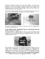
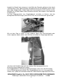
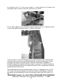
1
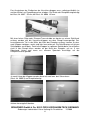
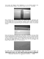
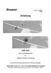
zu Best.-Nr. 6097
6098
Anleitung
Klapptriebwerk "up and go II "
GRAUPNER GmbH & Co. KG D-73230 KIRCHHEIM/TECK GERMANY
Änderungen vorbehalten! Keine Haftung für Druckfehler
1
12/2009
Technische Daten
Best.-Nr. 6098
Länge ca. 340 mm
Breite ca. 80 mm
Höhe ca. 130 mm
Gewicht ca. 1100 g
Aufnahmebohrung 20 mm
Für Segelflugmodelle mit
einer Spannweite von ca. 6000 mm
Abfluggewicht ca. 11 kg
Best.-Nr. 6097
Länge ca. 260 mm
Breite ca. 80 mm
Höhe ca. 110 mm
Gewicht ca. 800 g
Aufnahmebohrung 14 mm
Für Segelflugmodelle mit
einer Spannweite von ca. 4000 mm
Abfluggewicht ca. 6 kg
Achtung: Dieses Modell ist kein Spielzeug!
Sollten Sie mit solch motorisiertem Modell keine Erfahrung haben, wenden Sie sich
bitte an erfahrene Modellflieger, die Sie unterstützen können. Es könnte zu
Verletzungen kommen, wenn das Modell ohne Vorkenntnisse in Betrieb genommen
wird. Denken Sie an die Sicherheit und Ihre Gesundheit. Das Klapptreibwerk darf nur
verwendet werden um ein Segelflugmodell auf Höhe zu bringen. Es ist nicht gedacht
mit ausgefahrenem Klapptriebwerk Kunstflug / Speedflug zu machen.
Wichtig! Bevor Sie mit dem Einbau beginnen!
Auch wenn Sie schon viele RC-Modelle gebaut haben, lesen Sie diese Anleitung
genauestens durch. Es wurde viel Mühe darauf verwand, den Aufwand möglichst
gering zu halten, ohne die Sicherheit zu beeinträchtigen.
Sicherheitshinweise und Warnungen
•
•
•
•
•
•
•
•
Vor dem Versuch der ersten Inbetriebnahme muss die gesamte Betriebsund Montageanleitung sorgfältig gelesen werden.
Diese Sicherheitshinweise sind Bestandteil dieser Anleitung und müssen
zusammen mit der Bedienungsanleitung sorgfältig aufbewahrt und im Falle
einer Weitergabe dem nachfolgenden Benutzer unbedingt mit ausgehändigt
werden.
Ein Klapptriebwerk ist sehr anspruchsvoll und erfordert vom Betreiber
einen hohen Sachverstand, Können und Verantwortungsbewusstsein.
Nicht für Personen unter 18 Jahren geeignet.
Ein Betrieb darf nur unter Anleitung und Aufsicht eines Erwachsenen
erfolgen, der mit den sich daraus ergebenden Gefahren vertraut ist.
Der Betreiber muss im Besitz seiner vollen körperlichen und geistigen
Fähigkeiten sein. Wie beim Autofahren, ist der Betrieb unter Alkohol oder
Drogeneinwirkung nicht erlaubt.
Ferngesteuerte Flugmodelle dürfen nur für den vom Hersteller
vorgesehenen Zweck eingesetzt werden, also als nicht manntragendes
Sportgerät. Eine anderweitige Verwendung ist verboten.
Ein Modell kann nur funktionstüchtig sein und den Erwartungen
entsprechen, wenn es im Sinne der Bauanleitung sorgfältigst gebaut oder
GRAUPNER GmbH & Co. KG D-73230 KIRCHHEIM/TECK GERMANY
Änderungen vorbehalten! Keine Haftung für Druckfehler
2
12/2009
•
•
•
•
•
•
•
•
•
•
•
•
montiert wurde. Eigenmächtige Veränderungen von Konstruktion und
Material sind nicht zulässig. Nur ein vorsichtiger und überlegter Umgang
beim Betrieb schützt vor Personen- und Sachschäden. Niemand würde sich
in ein Sportflugzeug setzen und - ohne vorausgegangene Schulung versuchen, damit zu fliegen. Auch Modellfliegen will gelernt sein! Bitte
wenden Sie sich dazu an erfahrene Modellflieger, an Vereine oder
Modellflugschulen. Ferner sei auf den Fachhandel und die einschlägige
Fachpresse verwiesen.
Fernlenkanlage: Sich vergewissern, dass die verwendete Frequenz frei ist.
Erst dann einschalten! RC-Anlage öfters kontrollieren; auch sie ist
gewissem Verschleiß ausgesetzt. Funkstörungen, verursacht durch
Unbekannte, können stets ohne Vorwarnung auftreten! Das Modell ist dann
steuerlos und unberechenbar! Fernlenkanlage nie unbeaufsichtigt lassen,
um ein Betätigen durch Dritte zu verhindern. Immer auf vollgeladene Akkus
achten, da sonst keine einwandfreie Funktion der RC-Anlage gewährleistet
ist.
Warnungen müssen unbedingt beachtet werden. Sie beziehen sich auf
Dinge und Vorgänge, die bei einer Nichtbeachtung zu schweren - in
Extremfällen tödlichen Verletzungen oder bleibenden Schäden führen
können.
Sie alleine sind verantwortlich für den sicheren Betrieb Ihres Modells.
Fragen, die die Sicherheit beim Betrieb von Modell und Motor betreffen,
werden Ihnen vom Fachhandel gerne beantwortet.
Luftschrauben und generell alle sich drehenden Teile, die durch einen
Motor angetrieben werden, stellen eine ständige Verletzungsgefahr dar. Sie
dürfen mit keinem Körperteil berührt werden! Eine schnell drehende
Luftschraube kann z. B. einen Finger abschlagen!
Sich niemals in der Drehebene von Luftschrauben aufhalten! Es könnte sich
doch einmal ein Teil davon lösen und mit hoher Geschwindigkeit und viel
Energie wegfliegen und Sie oder Dritte Personen treffen. Darauf achten,
dass kein sonstiger Gegenstand mit einer laufenden Luftschraube in
Berührung kommt!
Vorsicht bei losen Kleidungsstücken wie Schals, weiten Hemden usw.: sie
werden
vom
Propellerstrahl
angesaugt
und
können
in
den
Luftschraubenkreis gelangen.
Informieren Sie alle Passanten und Zuschauer vor der Inbetriebnahme über
alle möglichen Gefahren, die von Ihrem Modell ausgehen und ermahnen
diese, sich in ausreichendem Schutzabstand (wenigstens 5 m) aufzuhalten.
Modellflug darf nur bei "normalen" Außentemperaturen betrieben werden, d.
h. in einem Bereich von - 5º C bis + 35º C. Extremere Temperaturen können
zu Veränderungen von z. B. Akku-Kapazität und Werkstoffeigenschaften
und anderem führen.
Motor nie in geschlossenen Räumen, wie Keller, Garage usw. laufen lassen.
Nur im Freien betreiben!
Klebstoffe und Lacke enthalten Lösungsmittel, die unter Umständen
gesundheitsschädlich sein können. Beachten Sie daher unbedingt auch die
entsprechenden Hinweise und Warnungen der entsprechenden Hersteller.
GRAUPNER GmbH & Co. KG D-73230 KIRCHHEIM/TECK GERMANY
Änderungen vorbehalten! Keine Haftung für Druckfehler
3
12/2009
•
•
•
•
•
•
•
•
•
•
•
•
•
Überprüfen Sie vor und nach jeder Inbetriebnahme das Modell und alle an
ihm angekoppelten Teile (z. B. Luftschrauben, Ruderanlenkungen, Ruder
usw.) auf mögliche Beschädigungen. Das Modell darf erst nach Beseitigung
aller Mängel in Betrieb genommen werden.
Steht ein Modell mit drehender Luftschraube z. B. auf sandigem Grund, so
wird Sand oder Staub angesaugt und herumgewirbelt, der auch ins Auge
fliegen kann. Schutzbrille tragen!
Nie Personen überfliegen.
Nie auf Personen zufliegen.
Auf ausreichenden Abstand zu Wohngebieten achten, mindestens 1,5 km
Luftlinie. Am besten als Club-Mitglied auf zugelassenem Modellflugplatz
fliegen. Ausreichenden Abstand zu Hochspannungsleitungen halten.
Während des Start- und Landevorgangs müssen die Start- und
Landeflächen frei von unbefugten Personen und beweglichen Hindernissen
sein.
Das Flugmodell muss während des gesamten Fluges ständig beobachtet
werden können. Es hat bemannten Luftfahrzeugen stets auszuweichen.
Betreiben Sie Ihr Modell nie auf öffentlichen Straßen, Plätzen, Schulhöfen,
Park- oder Spielplätzen usw. und sorgen Sie dafür, dass Sie es stets unter
voller Kontrolle haben.
Jeder Modellflieger hat sich so zu verhalten, dass die öffentliche Sicherheit
und Ordnung, insbesondere andere Personen und Sachen sowie die
Ordnung des Modellflugbetriebs nicht gefährdet oder gestört wird.
Rechtlich gesehen ist ein Flugmodell ein Luftfahrzeug und unterliegt
entsprechenden Gesetzen, die unbedingt eingehalten werden müssen.
Die Broschüre "Modellflugrecht, Paragrafen und mehr“, Best.-Nr. 8034.02,
stellt eine Zusammenfassung dieser Gesetze dar; sie kann auch beim
Fachhandel eingesehen werden. Bei Modellen mit Verbrennungsmotoren
muss z. B. eine Aufstiegserlaubnis vorliegen und es besteht
Versicherungspflicht. Ferner müssen Auflagen, die die Fernlenkanlage
betreffen, beachtet werden.
Mit diesen Hinweisen soll auf die vielfältigen Gefahren hingewiesen werden,
die durch unsachgemäße und verantwortungslose Handhabung entstehen
können. Richtig und gewissenhaft betrieben ist Modellflug eine kreative,
lehrreiche und erholsame Freizeitgestaltung.
Das weitgehend vorgefertigte Modell benötigt nur noch wenig Bauzeit. Aber
die verbleibenden Arbeiten sind wichtig und müssen sorgfältig ausgeführt
werden. Von deren einwandfreier Ausführung hängt es ab, ob das Modell
letztlich die vorgesehene Festigkeit und Flugeigenschaften haben wird;
deshalb langsam und präzise arbeiten!
Wichtige Sicherheitshinweise
Sie haben einen Bausatz erworben, aus dem – zusammen mit entsprechendem
geeigneten Zubehör – ein funktionsfähiges RC-Modell fertiggestellt werden kann. Die
Einhaltung der Montage- und Betriebsanleitung im Zusammenhang mit dem Modell
sowie die Installation, der Betrieb, die Verwendung und Wartung der mit dem Modell
zusammenhängenden Komponenten können von GRAUPNER nicht überwacht
werden. Daher übernimmt GRAUPNER keinerlei Haftung für Verluste, Schäden oder
GRAUPNER GmbH & Co. KG D-73230 KIRCHHEIM/TECK GERMANY
Änderungen vorbehalten! Keine Haftung für Druckfehler
4
12/2009
Kosten, die sich aus dem fehlerhaften Betrieb, aus fehlerhaftem Verhalten bzw. in
irgendeiner Weise mit dem vorgenannten zusammenhängend ergeben. Soweit vom
Gesetzgeber nicht zwingend vorgeschrieben, ist die Verpflichtung der Firma
GRAUPNER zur Leistung von Schadensersatz, aus welchem Grund auch immer
ausgeschlossen (inkl. Personenschäden, Tod, Beschädigung von Gebäuden sowie
auch Schäden durch Umsatz- oder Geschäftsverlust, durch Geschäftsunterbrechung
oder andere indirekte oder direkte Folgeschäden), die von dem Einsatz des Modells
herrühren.
Die Gesamthaftung ist unter allen Umständen und in jedem Fall beschränkt auf den
Betrag, den Sie tatsächlich für dieses Modell gezahlt haben.
Die Inbetriebnahme und der Betrieb des Modells erfolgt einzig und allein auf
Gefahr des Betreibers. Nur ein vorsichtiger und überlegter Umgang beim
Betrieb schützt vor Personen- und Sachschäden.
Prüfen Sie vor dem ersten Einsatz des Modells, ob Ihre PrivatHaftpflichtversicherung den Betrieb von Modellen dieser Art mit einschließt.
Schließen Sie gegebenenfalls eine spezielle RC-Modell-Haftpflichtversicherung ab.
Diese Sicherheitshinweise müssen unbedingt aufbewahrt werden und müssen bei
einem Weiterverkauf des Modells an den Käufer weitergegeben werden.
Garantiebedingungen
Die Garantie besteht aus Umtausch von solchen Teilen, die während der
Garantiezeit von 24 Monaten, ab dem Datum des Kaufes nachgewiesene
Fabrikations- oder Materialfehler aufweisen. Weitergehende Ansprüche sind
ausgeschlossen. Transport-, Verpackungs-, Fracht- und Fahrtkosten gehen zu
Lasten des Käufers. Für Transportschäden wird keine Haftung übernommen. Bei der
Einsendung an GRAUPNER bzw. an die für das jeweilige Land zuständige
Servicestelle sind eine sachdienliche Fehlerbeschreibung und die Rechnung mit dem
Kaufdatum beizufügen , die Transportkosten trägt der Käufer. Die Garantie ist
hinfällig, wenn der Ausfall des Teils oder des Modells von einem Unfall,
unsachgemäßer Behandlung oder falscher Verwendung herrührt.
Folgende Punkte müssen unbedingt beachtet werden:
• Kontrollieren Sie, bevor Sie das Modell starten, dieses auf eine sichere Funktion
der Fernsteuerung sowie die Steckverbindungen auf sichere und feste
Verbindung.
• Sämtliche Schraubverbindungen am Klapptriebwerk müssen in regelmäßigen
Abständen überprüft und wenn notwendig nachgezogen werden.
• Sollten sich Schrauben oder Muttern lösen, müssen diese mit UHU
schraubensicher gegen Lösen gesichert werden.
• Sämtliche Drehpunkte müssen in regelmäßigen Abständen durch einen Tropfen
Öl geschmiert werden.
• Muss die Luftschraubenaufnahme demontiert werden, muss bei der erneuten
Montage
sorgfältigst
darauf
geachtet
werden,
dass
die
vier
Befestigungsschrauben abwechselnd über Kreuz eine nach der anderen
festgezogen werden.
• Die Akkus müssen geladen und die Reichweite der Fernsteuerung muss
überprüft worden sein. Besonders die Sender- und Empfängerakkus müssen vor
jedem Start geladen werden.
GRAUPNER GmbH & Co. KG D-73230 KIRCHHEIM/TECK GERMANY
Änderungen vorbehalten! Keine Haftung für Druckfehler
5
12/2009
•
•
•
•
•
•
•
Prüfen Sie, ob der von Ihnen genutzte Kanal frei ist. Fliegen Sie niemals, wenn
Sie sich nicht sicher sind, ob der Kanal frei ist.
Beachten Sie die Empfehlungen und Hinweise zu Ihrer Fernsteuerung und
Zubehörteilen.
Achten Sie darauf, dass die Servos in ihrem Verfahrweg mechanisch nicht
begrenzt werden.
Batterien und Akkus dürfen nicht kurzgeschlossen werden.
Entnehmen Sie die Akkus bei Transport und Nichtgebrauch des Modells.
Setzen Sie das Modell nicht starker Luftfeuchtigkeit, Hitze, Kälte sowie Schmutz
aus.
Sichern Sie das Modell und RC-Komponenten beim Transport gegen
Beschädigung sowie Verrutschen.
Überprüfung vor dem Start
Vor jedem Einsatz korrekte Funktion und Reichweite überprüfen. Dazu
Senderantenne einschrauben und dann auf vollständige Länge ausziehen. Dann den
Sender einschalten, ebenso den Empfänger. Aus entsprechendem Abstand vom
Modell kontrollieren, ob alle Ruder einwandfrei funktionieren und in der richtigen
Richtung ausschlagen, dies gilt für 35 MHz Anlagen. Bei 2,4GHz Anlagen erfolgt der
Reichweitentest im speziellen Modus der Anlage.
Diese Überprüfung bei laufendem Motor wiederholen, während ein Helfer das Modell
festhält.
Beim erstmaligen Steuern eines Flugmodells ist es von Vorteil, wenn ein erfahrener
Helfer bei der Überprüfung und den ersten Flügen zur Seite steht. Pflege und
Wartung
• Säubern Sie das Modell nach jedem Gebrauch. Entfernen Sie Schmutzreste auch
vom Propeller. Säubern Sie das Modell und die RC-Komponenten nur mit
geeigneten Reinigungsmitteln. Informieren Sie sich hierzu bei Ihrem Fachhändler.
• Wenn das Modell längere Zeit nicht betrieben werden soll, müssen alle bewegten
Teile gesäubert und neu geschmiert werden.
Hinweise zum Einbau
• Vor dem Einbau sollte man unbedingt die Anleitung bis zum Schluss lesen.
• Achten Sie beim Einsatz von Werkzeugen auf die möglichen Gefahren.
• Verwenden Sie nur geeignete Kabel, die den im Betrieb auftretenden
Stromstärken genügen.
• Verlegen Sie die Empfangsantenne möglichst weit entfernt von den Fahrstrom
leitenden Kabeln (mindestens 3 cm).
GRAUPNER GmbH & Co. KG D-73230 KIRCHHEIM/TECK GERMANY
Änderungen vorbehalten! Keine Haftung für Druckfehler
6
12/2009
Für den Betrieb wird benötigt:
Bei Best.-Nr. 6098
Drehzahlregler Best.-Nr. 7228
Antriebsakku Best.-Nr. 7663.3 (2 Stück )
Ausfahrakku Best.-Nr. 7625.3
Schalterkabel Best.-Nr. 3934.4
bei Best.-Nr. 6097
Drehzahlregler Best.-Nr. 7236
Antriebsakku Best.-Nr. 7663.3
Ausfahrakku Best.-Nr. 7625.3
Schalterkabel Best.-Nr. 3934.4
Klappenscharnier 2 Stck. Best.-Nr. 3665.3
Klappenscharnier 2 Stck. Best.-Nr. 3665.3
Bereits montiert:
Luftschraube 45x25 cm
COMPACT 655/20 Volt
Luftschraube 36x20 cm
COMPACT 540/14,4 Volt
Vorwort
Durch den Einbau eines Klapptriebwerkes wird Ihr Segelflugmodell bei geeigneter
Startbahn bodenstartfähig.
Eine Außenlandung bei Hangfliegen wird nicht mehr notwendig.
Zum Einbau des Klapptriebwerks reicht eine relativ kleine Rumpföffnung.
Das Klapptriebwerk ist in beiden Endstellungen verriegelt.
Durch ein Schneckengetriebe ist ein sicheres Ein- und Ausfahren gewährleistet.
Montage an der Tragflächenaufnahme möglich.
Der Neigungswinkel des Klapptriebwerks ist einstellbar.
Beim Einbau eines Einziehfahrwerks hat es sich bewährt, wenn die Radachse bei
ausgefahrenem Fahrwerk ca. 20 – 30 mm vor der Nasenleiste der Tragfläche ist.
Je nach Fernsteuerung reicht zum Ausfahren und Betätigen des Antriebmotors ein
Drei-Stufenschalter der entsprechend programmiert wird.
Kurz gesagt: hintere Stellung Klapptriebwerk eingefahren und selbstverständlich EMotor aus, Mittelstellung: Klapptriebwerk fährt aus, Drehzahlregler wird in der
Endstellung scharf geschaltet. Vordere Stellung E-Motor läuft.
In der Praxis hat es sich bewährt, dem Regler eine Zeit von ca. 5 Sekunden
einzuprogrammieren in der er von Null auf Vollgas hochregelt. In der gleichen Zeit
wird durch einen Mischer je nach Modell ein entsprechender Höhenruderausgleich
aktiv. Beim Ausschalten des Antriebsmotors stellt sich dann das Höhenruder wieder
auf neutral.
Einbau des Klapptriebwerks "up and go II
Es gibt zwei Möglichkeiten das Klapptriebwerk einzubauen. Zum Einen, dass es an
der Rundstahlaufnahme befestigt wird, zum Anderen an einem separaten Spant der
kurz hinter der Tragflächenaufnahme in den Rumpf geklebt, an den das
Klapptriebwerk von vorne angeschraubt werden kann. Zum Anzeichnen der
Verschlussklappen des Rumpfes muss das Klapptriebwerk im eingefahren Zustand
auf die Rumpfseite gelegt werden. Hierbei ist auf die richtige Einbauhöhe zu achten,
dass es später auch durch die Verschlussklappen abgedeckt wird. In dieser Position
die hintere Kante ca. 20mm und vordere Kante der Verschlussklappen ca. 10 mm
länger als Motorkante bzw. Luftschraubenspitzen anzeichnen. Zur Kontrolle der
Vorderkante das Klapptriebwerk im ausgefahrenen Zustand auf die Rumpfseite
legen, evtl. muss der Anriss leicht korrigiert werden.
GRAUPNER GmbH & Co. KG D-73230 KIRCHHEIM/TECK GERMANY
Änderungen vorbehalten! Keine Haftung für Druckfehler
7
12/2009
Das Anzeichnen der Endkanten der Verschlussklappen muss selbstverständlich im
rechten Winkel zur Rumpflängsachse erfolgen. Die Breite der Rumpföffnung beträgt
bei Best.-Nr. 6097 55 mm, bei Best.-Nr. 6098 65 mm.
Mit einer feinen Säge oder Diamant-Trennscheibe am besten an einem Stahllineal
entlang, werden nun die Verschlussklappen aus dem Rumpf herausgesägt. Das
herausgetrennte Teil in der Mitte, der Naht des Rumpfes entlang, trennen so dass
zwei Klappen vorliegen, rechts und links kennzeichnen. Die Schnittkanten mit feinem
Schleifpapier versäubern. Damit die Klappen im späteren Betrieb beim Verschließen
nicht in den Rumpf fallen, werden an der Naht des Rumpfes, mit ca. 3 mm
Überstand, hinten und vorne aus dünnem Sperrholz Anschläge auf die
Rumpfinnenseite geklebt.
Je nach Länge der Klappen werden diese mit zwei bzw. drei Scharnieren
(Best.-Nr. 3665.3) am Rumpf befestigt.
Für die Scharniere (Best.-Nr. 3665.3) müssen aus dem Rumpf Aussparungen,
4x8mm herausgefeilt werden.
GRAUPNER GmbH & Co. KG D-73230 KIRCHHEIM/TECK GERMANY
Änderungen vorbehalten! Keine Haftung für Druckfehler
8
12/2009
Jetzt werden die Klappen mittels Klebeband so an den Rumpf geheftet, dass
zwischen den beiden Klappen, in der Mitte ein Spalt von ca. 0,5 – 1mm bleibt.
Beim Anheften der Scharnierhälften ist es wichtig, dass die Drehachsen der
einzelnen Scharniere auf einer Linie liegen. Die Scharnierhälften mit Sekundenkleber
an die Klappen bzw. die Innenseite des Rumpfes heften, dabei die einzelnen
Scharniere mit einem entsprechend langen Draht verbinden, so dass sie zueinander
fluchten.
Damit die Scharniere dauerhaft halten, sollte jedes Scharnierteil mit einem Stück
Glasgewebe/Epoxydharz angeklebt werden. Nach dem Trocknen, entsprechend dem
Foto, aus Stahldraht Ø 0,6 mm Torsionsfedern biegen, darauf achten, dass eine linke
und eine rechte Feder gebogen wird. Die Länge der Torsionsfeder richtet sich nach
der Länge der Klappen. Sie sollten ca. 100 mm kürzer sein als die Klappen. Die
beiden Federschenkel sollten ca. 15 mm lang sein.
Die beiden Enden der Torsionsfedern werden zum Einen an die Klappe zum
Anderen an die Innenseite des Rumpfes geklebt. Hierbei ist darauf zu achten, dass
GRAUPNER GmbH & Co. KG D-73230 KIRCHHEIM/TECK GERMANY
Änderungen vorbehalten! Keine Haftung für Druckfehler
9
12/2009
genügend Vorspannung erreicht wird, damit die Klappen sich später auch
zuverlässig schließen. In der Mitte der Torsionsfeder sollte diese mit einem Tropfen
Klebstoff an die Verschlussklappen geheftet werden. Beim Ausfahren des
Klapptriebwerks öffnen sich die Verschlussklappen automatisch und schließen sich
wieder beim Einfahren des Klapptriebwerks.
An der linken Seite der Mechanik befindet sich ein 3-poliger Mikroschalter. An diesen
wird ein Servoverlängerungskabel wie auf dem Foto zu sehen angelötet.
Durch diesen Mikroschalter wird später nach dem Ausfahren des Klapptriebwerks
der Regler "scharf" geschaltet.
Je nach Modell kann das Klapptriebwerk direkt am Rundstahl oder separaten
Spanten befestigt werden. Die einfachste Lösung ist die Befestigung an der
Rundstahlaufnahme der Tragflächen.
Bei der Befestigung an separaten Spanten, müssen je nach vorhandenem Rumpf
zwei Spanten aus 6 mm Buchesperrholz an entsprechender Stelle in den Rumpf
eingepasst werden. Diese Spanten werden dann waagerecht rechts und links in den
Rumpf geklebt ( siehe Foto).
Beim Einkleben in den Rumpf muss unbedingt darauf geachtet werden, dass, bei
ausgefahrenem Klapptriebwerk die Motorachse parallel zur Rumpflängsachse
verläuft . Dies ist wichtig, da hiervon die Flugeigenschaften abhängen. Das
Klapptriebwerk wird dann mittels der beiden Aluminiumwinkel und dem passenden
Messingrohr so an die Spanten geschraubt, dass es im eingefahrenen Zustand
GRAUPNER GmbH & Co. KG D-73230 KIRCHHEIM/TECK GERMANY
Änderungen vorbehalten! Keine Haftung für Druckfehler
10
12/2009
komplett im Rumpf liegt und genau in der Mitte des Rumpfes geklemmt wird, damit
sichergestellt ist, dass beim Ausfahren die Mechanik nicht am Rumpfausschnitt streift
oder sogar hängen bleibt. Hierbei liegen die Aluminiumwinkel rechts und links an der
Mechanik an. Mit den beiden Inbusschrauben wird das Messingrohr in der Mechanik
festgeklemmt.
Um den Neigungswinkel des Klapptriebwerks einstellen zu können wird die
beiliegende Aluminiumstange (Querschnitt 12x3 mm) an die Mechanik geschraubt.
Wie auf dem Foto zu sehen, an den vorderen Spant vom Einziehfahrwerk oder
einem separaten Spant mittels einer M3 Inbusschraube das Gegenlager befestigt.
Gegenlager
Jetzt kann die Querbohrung sprich der vordere Befestigungspunkt an der
Aluminiumstange angezeichnet werden.
Das Klapptriebwerk in Stellung ausgefahren bringen, hierzu muss die RC-Anlage
kurz in Betrieb genommen werden. Das Klapptriebwerk muss nun so ausgerichtet
werden, dass später bei laufendem Motor das Höhenleitwerk angestrahlt wird. Diese
GRAUPNER GmbH & Co. KG D-73230 KIRCHHEIM/TECK GERMANY
Änderungen vorbehalten! Keine Haftung für Druckfehler
11
12/2009
Stellung ist wichtig, damit beim Bodenstart das Höhenleitwerk, sprich der Rumpf, auf
den Boden gedrückt werden.
Für einen sicheren Betrieb des Klapptriebwerks ist es wichtig zwischen
Klapptriebwerk und Ausfahrakku einen EIN/AUS-Schalter zu schließen, da auch in
Ruhestellung ein geringer Strom fließt.
Nun bleibt nur noch viel Spaß und Freude beim Fliegen mit Ihrem Klapptriebwerk “up
and go II“ zu wünschen.
Ihr
Team !
GRAUPNER GmbH & Co. KG D-73230 KIRCHHEIM/TECK GERMANY
Änderungen vorbehalten! Keine Haftung für Druckfehler
12
12/2009
Order No. 6097
6098
Instructions
“up and go II” retractable motor
GRAUPNER GmbH & Co. KG D-73230 KIRCHHEIM/TECK GERMANY
Änderungen vorbehalten! Keine Haftung für Druckfehler
13
12/2009
Specifications
Order No. 6098
Length approx.
Width approx.
Height approx.
Weight approx.
Pivot holes
For model gliders with
a wingspan of approx.
All-up weight approx.
340 mm
80 mm
130 mm
1100 g
20 mm Ø
6000 mm
11 kg
Order No. 6097
Length approx.
Width approx.
Height approx.
Weight approx.
Pivot holes
For model gliders with
a wingspan of approx.
All-up weight approx.
260 mm
80 mm
110 mm
800 g
14 mm Ø
4000 mm
6 kg
Caution: this model is not a toy!
If you are a beginner to this type of powered model, please ask an experienced
model flyer for help and support. If you attempt to operate the model without knowing
what you are doing, you could easily injure yourself or somebody else. Please keep
your safety and well-being in mind at all times. This retractable power unit is
designed solely as a means of powering a model sailplane to gliding height.
Aerobatics or speed flying should not be attempted with the motor extended.
Important: before you start installing the unit
Even if you have already built many radio-controlled models, please take the time to
read right through these instructions. We have invested a lot of effort in them in order
to minimise the work you have to do, but without adversely affecting safety.
Safety Notes and Warnings
•
•
•
•
•
•
•
•
Be sure to read right through the installation instructions and operating
instructions before using the system for the first time.
These safety notes are an integral part of the operating instructions, and
must be stored carefully together with those instructions. If you ever
dispose of the system, please pass them on to the new owner.
A retractable motor is a very demanding piece of equipment, and requires a
high level of technical knowledge, skill and sense of responsibility on the
part of the operator.
Not suitable for persons under eighteen years of age.
The system should only be operated under the instruction and supervision
of an adult who is conversant with the hazards involved in its use.
The operator of the model must be in full possession of his or her bodily
and mental faculties. As with car driving, flying a model aircraft under the
influence of alcohol or drugs is highly dangerous and not permissible under
any circumstances.
Radio-controlled model aircraft may only be employed for the purpose
intended by the manufacturer, i.e. as sport machines which do not carry
humans. Any other usage is prohibited.
A radio-controlled model aircraft can only work properly and fulfil your
expectations if it is built very carefully and in accordance with the building
instructions. If you wish to avoid injuring people and damaging property, it
GRAUPNER GmbH & Co. KG D-73230 KIRCHHEIM/TECK GERMANY
Änderungen vorbehalten! Keine Haftung für Druckfehler
14
12/2009
•
•
•
•
•
•
•
•
•
•
•
•
•
is essential to be careful and painstaking at all stages of building and
operating your model. Model flying is a skill which has to be acquired, and
this demands plenty of practice. If you are a beginner, please contact an
experienced model flyer, your local club or a model flying school. Your
nearest model shop and the specialist model magazines are also excellent
sources of help and information.
Radio control system: satisfy yourself that your frequency is vacant before
you switch on. Check your RC system regularly; like most other equipment
it is subject to wear. Radio interference caused by unknown sources can
occur at any time without warning. If this should happen, your model will be
uncontrollable and completely unpredictable. Never leave your radio control
system unguarded, as another person might pick it up and try to use it.
Take the trouble to keep your batteries fully charged, as the radio control
system cannot function reliably without properly maintained batteries.
Please don’t ignore our warnings. They refer to hazardous materials and
processes which, if ignored, can result in fatal injury or serious damage to
property.
You alone are responsible for the safe operation of your radio-controlled
model.
If you have any questions regarding the safe operation of your RC model
aircraft, please turn to your local model shop in the first instance, where the
staff will be pleased to help you.
Propellers and other rotating parts which are powered by a motor constitute
a permanent hazard and represent a real risk of injury. Don’t touch them
with any part of your body. For example, a propeller spinning at high speed
can easily slice off your finger.
Keep well clear of the rotational plane of the propeller. You never know
when some part may come loose and fly off at high speed, striking you or
anybody else in the vicinity. Never touch the revolving propeller with any
object.
Take care with loose clothing such as scarves, loose shirts etc. Flapping
cloth can easily be sucked into the area of the propeller and then get
tangled in the blades; this is extremely dangerous.
If there are passers-by and spectators present, be sure to inform them of
the possible hazards involving your model, and request them to stay a safe
distance away (at least five metres) from the model.
Radio-controlled models should only be flown in “normal” weather
conditions, i.e. a temperature range of -5° to +35°C. More extreme
temperatures can lead to changes in battery capacity, material
characteristics and other unwanted effects.
Never run an engine or electric motor in an enclosed space such as a cellar,
garage etc.
Motors and engines should only be operated in the open air!
Adhesives and paints contain solvents which may be hazardous to health
under certain circumstances. Read and observe the notes and warnings
supplied by the manufacturer of these materials.
Every time you intend to operate your model, check carefully that it and
everything attached to it (e.g. propeller, servo linkages, control surfaces
GRAUPNER GmbH & Co. KG D-73230 KIRCHHEIM/TECK GERMANY
Änderungen vorbehalten! Keine Haftung für Druckfehler
15
12/2009
•
•
•
•
•
•
•
•
•
•
•
•
etc.) is in good condition and undamaged. If you find a fault, do not fly the
model until you have corrected it.
When a model is standing on a loose or sandy surface with the propeller
spinning, sand or dust will be sucked up by the propeller and hurled
around. Eye injury hazard: wear protective goggles!
Never fly directly over people.
Never fly directly towards people.
Keep an adequate distance from residential areas: at least 1.5 km “as the
crow flies”. It is always best to join a club and fly at the approved model
flying site. Keep well clear of high-tension overhead cables.
During the take-off and landing procedures it is essential to keep the
runway free of unauthorised persons and movable obstacles.
Watch your model aircraft constantly for every moment it is in the air.
Models must always give way to full-size aircraft.
Don’t operate your model in the vicinity of public roads, squares, school
playgrounds, public parks or sports fields etc., and ensure that you are
always in full control of the model.
All model flyers should behave in a way which minimises the risk to public
security and order, and danger to people and property. Never act in any
manner which will disturb other pilots, or is likely to have an adverse effect
on safe, orderly flying at the site.
In legal terms our models are classed as aircraft, and as such are subject to
statutory regulations and restrictions which must be observed.
Our brochure “Modellflugrecht, Paragrafen und mehr” (Model Aviation Law,
Legal Requirements and more) is available under Order No. 8034.02, and
contains a summary of all these rules; your local model shop should have a
copy which you can read. Models powered by internal-combustion engines
usually require permission from the landowner before they can be flown.
Insurance is a basic requirement. There are also Post Office regulations
concerning your radio control system, and these must be observed.
Please don’t misunderstand the purpose of these notes. We only want to
make you aware of the many dangers and hazards which can arise if you act
carelessly or irresponsibly. If you take reasonable care, model flying is a
highly creative, instructive, enjoyable and relaxing pastime.
Our models are highly pre-fabricated, and require only a short time to
complete them. However, the work entrusted to you is important, and must
be carried out carefully. Your model can only perform to its best and be
structurally strong if you carry out your part competently, so please work
slowly and accurately.
Important Safety Notes
You have acquired a power system which can be installed as part of a fully working
RC model. However, we as manufacturers have no control over the way you build
and operate your RC model aircraft, nor how you install, operate and maintain the
associated components, and for this reason we are obliged to deny all liability for
loss, damage or costs which are incurred due to the incompetent or incorrect use and
operation of our products, or which are connected with such operation in any way.
GRAUPNER GmbH & Co. KG D-73230 KIRCHHEIM/TECK GERMANY
Änderungen vorbehalten! Keine Haftung für Druckfehler
16
12/2009
Unless otherwise prescribed by binding law, the obligation of the GRAUPNER
company to pay compensation, regardless of the legal argument employed, is
excluded. This includes personal injury, death, damage to buildings, damage due to
loss of business or turnover, interruption of business or other direct or indirect
consequent damage whose root cause was the operation of the model.
The total liability in all cases is limited to the amount of money which you actually
paid for the model.
The model is built and flown at the sole and express responsibility of the
operator. The only way to avoid injury to persons and damage to property is to
handle and operate the model with the greatest care and consideration at all
times.
If you are not sure whether your normal household insurance policy covers the risks
involved in operating RC models, please take out a special third party policy which
specifically covers model flying.
These safety notes must be kept in a safe place. If you ever dispose of the model, be
sure to pass them on to the new owner.
Guarantee conditions
The guarantee covers replacement of any parts which can be shown to exhibit
manufacturing faults or material defects within the guarantee period of 24 months
from the initial date of purchase. No other claims will be considered. Cost of
transport, packing and freight are payable by the purchaser. We accept no liability for
damage in transit. When you send the product to GRAUPNER, or to the approved
Service Centre for your country, you must include a clear and concise description of
the fault together with the invoice showing the date of purchase. Transport costs are
payable by the purchaser. The guarantee is invalid if the component or model fails
due to an accident, incompetent handling or incorrect usage.
The following points are important, and must be observed at all times:
• Before you fly the model, check that the radio control system is working reliably,
and that all plug-in connections are firmly seated.
• All the screwed connections on the retractable motor unit must be checked at
regular intervals, and tightened if and when necessary.
• If screws or nuts work loose, apply a drop of UHU schraubensicher (thread-lock
fluid) to prevent a re-occurrence.
• All pivot points should be lubricated at regular intervals with a drop of oil.
• If you are obliged to dismantle the propeller driver, please take great care to
ensure that the four fixing screws are re-tightened “cross-wise”, i.e. first one
screw, then the opposite one, and so on.
• The batteries must be given a full charge before the model is flown. It is
important to check the effective range of the radio control system. It is essential
that the transmitter and receiver batteries should be fully charged before each
flying session.
• Ensure that the frequency you intend to use is not already in use by other
modellers. Never fly your model if you are not certain that your channel is free.
• Read and observe the instructions and recommendations supplied with your
radio control system and accessories.
GRAUPNER GmbH & Co. KG D-73230 KIRCHHEIM/TECK GERMANY
Änderungen vorbehalten! Keine Haftung für Druckfehler
17
12/2009
•
•
•
•
•
Check that your servos are not mechanically obstructed at any point in their full
travel.
Dry cells and rechargeable batteries must never be short-circuited - fire hazard.
Remove the rechargeable battery if the model is to be transported, or will not be
used for a long period.
Do not subject the model to high levels of humidity, heat, cold or dirt.
Secure the model and your RC equipment carefully when transporting them.
They may be seriously damaged if they are free to slide about.
Pre-flight checks
Before every flying session check that all the radio control functions are working
properly, and carry out a range check: for 35 MHz systems this means fitting the
transmitter aerial and extending it to full length. Switch the transmitter on, followed by
the receiver. Walk away from the model and check at an appropriate distance that all
the controls work properly, and that the control surfaces deflect in the correct “sense”
(direction) relative to the stick movements. If you are using a 2.4 GHz system the
range check is carried out using a special mode which varies from system to system.
Repeat the check with the motor running, while a friend holds the model securely.
If you are flying a model aircraft for the first time we strongly recommend that you ask
an experienced modeller to check the aeroplane first and be ready to help you during
the first few flights.
Care and maintenance
• The model should be cleaned after every session. Remove all traces of dirt from
the propeller. The model and RC system components should be cleaned using
suitable cleaning agents only; please ask your model shop for advice on this.
• If the model will not be flown for a protracted period, clean and re-lubricate all the
moving parts.
Installation notes
• Before installing the system it is essential to read right through these instructions.
• Please be aware of the hazards involved in the use of tools.
• All cables employed must be suitable for the currents which will flow when the
system is in operation.
• Deploy the receiver aerial as far away as possible (at least 3 cm) from highcurrent cables.
The following items are required to operate the system:
For Order No. 6098
Speed controller, Order No. 7228
Flight battery, Order No. 7663.3 (2 off)
Extend battery, Order No. 7625.3
Switch harness, Order No. 3934.4
Flap hinge, pack of 2, Order No. 3665.3
For Order No. 6097
Speed controller, Order No. 7236
Flight battery, Order No. 7663.3
Extend battery, Order No. 7625.3
Switch harness, Order No. 3934.4
Flap hinge, pack of 2, Order No. 3665.3
GRAUPNER GmbH & Co. KG D-73230 KIRCHHEIM/TECK GERMANY
Änderungen vorbehalten! Keine Haftung für Druckfehler
18
12/2009
Already fitted:
Propeller, 45 x 25 cm
COMPACT 655 / 20 Volt
Propeller, 36 x 20 cm
COMPACT 540 / 14.4 Volt
Introduction
Installing a retractable motor gives your model glider the ability to take off from the
ground if a suitable runway is available.
At the slope the system removes the fear of an out-landing when the lift fails.
A relatively small opening in the fuselage is sufficient for the retractable motor pylon.
The retractable motor locks at both end-points of its travel.
A worm gearbox guarantees reliable extension and retraction.
The system can be mounted on the wing joiner sleeve.
The angle of inclination (tilt) of the retractable motor is variable.
If a retractable wheel is installed, experience shows that the wheel axle should be
around 20 - 30 mm forward of the wing root leading edge when extended.
In most cases a simple three-position switch suffices to extend and control the drive
motor; the transmitter programming required varies according to your RC system.
In brief: ‘switch back’ equates to motor retracted, and - naturally - electric motor off.
‘Switch centre’ extends the motor; at the end-point the speed controller is armed.
‘Switch forward’ causes the motor to run.
Practice has shown that the ‘zero to full-throttle’ time should be programmed to about
five seconds. During the same period elevator trim compensation is activated by an
automatically triggered mixer; the amount of compensation varies according to the
specific model. When the motor is switched off, the elevator returns to the normal
neutral position.
Installing the “up and go II” retractable motor system
There are two methods of installing the retractable motor pylon: the first option is to
attach it to the glider’s wing joiner sleeve, the second is to mount it on separate
formers which are bonded into the fuselage just aft of the wing joiner; in this case the
motor system can be screwed to the formers from the front. The first step is to place
the retractable motor unit on the fuselage in the retracted state, so that you can mark
the position of the doors which seal off the motor opening. Note the correct installed
height of the system at this point; you must ensure that the system does not foul the
doors when it is retracted. In this position mark the outline of the required opening: at
one end the edge should be around 20 mm longer than the propeller tips; at the other
about 10 mm longer than the end of the motor. To check the position of the front end
of the motor unit you should lay the retracted mechanism on the side of the fuselage;
you may then need to correct the marked outline slightly.
Naturally both ends of the opening must be marked exactly at right-angles to the
fuselage centreline. For Order No. 6097 the width of the opening in the fuselage
should be 55 mm, for Order No. 6098 the width is 65 mm.
GRAUPNER GmbH & Co. KG D-73230 KIRCHHEIM/TECK GERMANY
Änderungen vorbehalten! Keine Haftung für Druckfehler
19
12/2009
The doors can now be sawn out of the fuselage, ideally with a fine-blade saw or a
diamond cut-off disc, using a steel straight edge as a guide. Carefully divide the
piece removed from the fuselage down the centreline (moulding seam) to produce
the two doors; mark the left and right doors, and clean up the cut edges with fine
abrasive paper. To prevent the doors falling inside the fuselage when closed, cut
small stop-pieces from thin plywood and glue them centrally to the inside of the
fuselage as shown, projecting into the opening by about 3 mm front and rear.
Each door is attached to the fuselage using two or three hinges, (Order No. 3665.3)
according to length.
You will need to file out 4 x 8 mm notches for the hinges (Order No. 3665.3) in the
fuselage.
Now tape the doors to the fuselage, leaving a gap about 0.5 - 1 mm wide along the
centre.
GRAUPNER GmbH & Co. KG D-73230 KIRCHHEIM/TECK GERMANY
Änderungen vorbehalten! Keine Haftung für Druckfehler
20
12/2009
The next step is to tack the hinges in place; it is important to ensure that the pivot
axes of the individual hinges are exactly in line. Slip a full-length piece of wire
through the row of hinges on each side to keep them exactly in line, then use cyano
to tack the hinge components to the doors and the inside of the fuselage.
Each hinge should finally be reinforced with a patch of glass cloth and epoxy to
ensure that they do not come adrift in the long-term. When the resin has cured, bend
a pair of torsion springs from 0.6 mm Ø spring steel wire to the shape shown in the
photo, taking care to produce a handed pair (different left and right). The length of the
torsion springs varies according to the length of the doors: they should be around
100 mm shorter than the door panels. The angled ends are around 15 mm long.
Glue one end of the torsion spring to the door, the other to the inside of the fuselage.
It is important that the springs should be under sufficient tension when installed, to
ensure that the doors close reliably. Fix the centre of each torsion spring to the doors
with a drop of adhesive. When the motor pylon is extended, the doors open
automatically, and close again when the system is retracted.
GRAUPNER GmbH & Co. KG D-73230 KIRCHHEIM/TECK GERMANY
Änderungen vorbehalten! Keine Haftung für Druckfehler
21
12/2009
You will find a three-pole micro-switch on the left-hand side of the mechanism: solder
a servo extension lead to the contacts as shown in the photo.
The purpose of this micro-switch is to “arm” the speed controller once the motor
pylon has been extended.
There are two methods of installing the retractable motor system: it can be attached
directly to the wing joiner sleeve, or mounted on separate formers in the fuselage.
The simplest solution is to fix it to the sleeve for the wing joiner rod.
If you opt for separate formers, you will need to cut the two wooden supports from 6
mm beech plywood to suit your glider’s fuselage, and trim them carefully to fit at the
appropriate point. These formers should then be glued horizontally to both sides of
the fuselage, as shown in the photo.
It is absolutely essential to position the formers in such a way that the motor axis lies
parallel to the fuselage centreline when the motor pylon is extended. This point is
important, since the model’s flying characteristics depend upon it. The retractable
motor unit is then screwed to the formers, using the two aluminium brackets and the
appropriate brass tube. Check that the system is completely enclosed inside the
fuselage in the retracted state, and is aligned exactly in the centre of the fuselage,
otherwise the mechanism could foul or be obstructed by the edges of the fuselage
opening. Note that the aluminium brackets should rest against both sides of the
mechanism. Clamp the brass tube in the mechanism by tightening the two sockethead cap screws.
GRAUPNER GmbH & Co. KG D-73230 KIRCHHEIM/TECK GERMANY
Änderungen vorbehalten! Keine Haftung für Druckfehler
22
12/2009
An aluminium bar (12 x 3 mm cross-section) is used to adjust the tilt angle of the
retractable motor; screw this bar to the mechanism as shown.
Fix the front support to the retractable undercarriage former (or a separate former),
using an M3 socket-head cap screw, as shown in the photo.
Gegenlager
The cross-hole, i.e. the front fixing point, can now be marked on the aluminium bar:
move the mechanism to the fully extended position using the radio control system,
and adjust the angle of the motor pylon so that the airflow from the propeller is
directed straight at the tailplane when the motor is running. This setting is important,
as you need to be able to push the tailplane (and with it the fuselage) down onto the
ground during the take-off run.
For reliable operation of the retractable motor system it is important to wire an ON /
OFF switch in the circuit between the motor unit and the extend battery, otherwise
the battery will be flattened by the small current which flows when the system is at
idle.
GRAUPNER GmbH & Co. KG D-73230 KIRCHHEIM/TECK GERMANY
Änderungen vorbehalten! Keine Haftung für Druckfehler
23
12/2009
Now all that remains is to wish you many hours of pleasure flying your model with the
“up and go II” retractable motor system.
Yours - the
team !
GRAUPNER GmbH & Co. KG D-73230 KIRCHHEIM/TECK GERMANY
Änderungen vorbehalten! Keine Haftung für Druckfehler
24
12/2009
Réf. N° 6097
6098
Instructions
Propulsions rétractables"up and go II "
Caractéristiques techniques
Réf. N°6098
Longueur, env.
340mm
Largeur, env.
80mm
Hauteur, env.
130mm
.
Poids, env.
1100 g.
Alésage de moyeu 20mm
Pour modèle de planeur d’une
envergure d’env. 6000mm
Poids au décollage, env. 11 Kg.
Réf. N°6097
Longueur, env.
260mm
Largeur, env.
80mm
Hauteur, env.
110mm
Poids, env.
800 g.
Alésage de moyeu 14mm
Pour modèle de planeur d’une
envergure d’env. 4000mm
Poids au décollage, env. 6 Kg
Attention: Un modèle équipé de cette propulsion n’est pas un jouet !
Si vous n’avez encore aucune expérience avec ces genres de modèles motorisés,
adressez vous à un modéliste expérimenté qui pourra vous assister. Des blessures
peuvent être causées lorsque ces modèles sont utilisés sans connaissances
préalables ; pensez à la sécurité et à votre santé. Les propulsions rétractables
devront être utilisées uniquement pour faire monter un modèle de planeur en altitude.
Il n’est pas pensable de faire de la voltige ou du vol de vitesse avec la propulsion
rétractable en position sortie.
Important: A lire avant de commencer le montage!
Même si vous avez déjà construit de nombreux modèles R/C, lisez attentivement et
entièrement ces instructions. Beaucoup d’efforts ont été faits pour rendre le montage
le plus simple possible, sans pour autant nuire à la sécurité.
Conseils de sécurité et avertissements
Avant de tenter la première mise en service, la totalité des instructions de
montage et d’utilisation devra être attentivement lue.
Ces conseils de sécurité font partie de ces instructions et devront être
soigneusement conservés avec les instructions de montage et remises à
l’utilisateur suivant dans le cas où la propulsion rétractable lui sera cédée.
Une propulsion rétractable est très exigeante et nécessite de son utilisateur
une haute compréhension et des connaissances spéciales, ainsi que la
conscience de sa responsabilité.
Son utilisation ne convient pas aux personnes en dessous de 18 ans.
GRAUPNER GmbH & Co. KG D-73230 KIRCHHEIM/TECK GERMANY
Änderungen vorbehalten! Keine Haftung für Druckfehler
25
12/2009
L’utilisation d’une propulsion rétractable doit se faire uniquement sous les
instructions et la surveillance d’un adulte compétent et familiarisé avec les
dangers qu’elle peut présenter.
L'utilisateur doit être en pleine possession de ses facultés physiques et
mentales. Comme pour la conduite des automobiles, le pilotage d'un
modèle réduit sous l'effet de l'alcool ou de la drogue n'est pas autorisé.
Les modèles volants R/C doivent être utilisés uniquement dans les
conditions prévues par le fabricant, pour le sport et le loisir. Toute autre
utilisation est interdite.
Un modèle volant ne peut évoluer correctement que s'il a été construit et
réglé conformément aux instructions de montage. Des modifications dans
la construction et dans les matériaux utilisés ne sont pas admissibles.
Seule une utilisation prudente et responsable évitera de causer des
dommages personnels et matériels. Personne ne peut prétendre prendre
place dans un avion de tourisme et le piloter sans un apprentissage
préalable. Il faut aussi apprendre à piloter un modèle réduit! Vous pouvez
vous adresser pour cela à un modéliste expérimenté, vous inscrire dans un
club d'aéromodélisme ou dans une école de pilotage. Vous pourrez en outre
consulter votre revendeur ou la presse spécialisée sur le sujet.
Ensemble R/C : Assurez vous que la fréquence que vous utilisez est libre
avant de mettre votre émetteur en contact ! Vérifiez régulièrement votre
ensemble R/C, même s’il semble être en bon état. Des perturbations
peuvent toujours se produire pour une cause quelconque et sans prévenir.
Le modèle devient alors incontrôlable et livré à lui-même. Ne laissez pas
votre ensemble R/C sans surveillance pour éviter qu’il soit manipulé par un
tiers. Veillez toujours à la pleine charge des accus, car autrement aucune
fonction impeccable de l’ensemble R/C ne peut être garantie.
Ces avertissements devront être impérativement observés. Leur non
observation peut conduire à de sérieuses blessures et même mortelles
dans les cas extrêmes, ou à des dégâts irréparables.
Vous être seul responsable de la sécurité d’utilisation de votre modèle.
Si vous avez une question concernant l'utilisation de votre modèle et de sa
propulsion, votre revendeur habituel vous renseignera volontiers.
Les hélices et en général toutes les pièces mécaniques entraînées par un
moteur présentent un danger de blessures permanent et ne doivent être
touchées par aucune partie du corps! Une hélice tournant à haut régime
peut par ex. couper un doigt!
Ne vous tenez jamais dans le champ de rotation d'une hélice! Une pièce
peut se détacher et être éjectée à haute vitesse avec une forte inertie et
vous toucher, ou une tierce personne. Veillez également à ce qu'aucun
objet quelconque vienne en contact avec l'hélice en rotation.
Veillez également aux vêtements flottants tels qu'écharpe ou cravate,
etc…qui peuvent être aspirés et s'enrouler sur l'hélice.
Avant de faire voler votre modèle, informez tous les passants et les
spectateurs sur les possibilités de danger qu'il peut présenter et demandezleur de se tenir à une distance de sécurité (au moins 5 mètres).
Un modèle volant R/C ne doit être utilisé que par des températures
extérieures normales, c'est-à-dire dans une plage comprise entre –5° à +35°
GRAUPNER GmbH & Co. KG D-73230 KIRCHHEIM/TECK GERMANY
Änderungen vorbehalten! Keine Haftung für Druckfehler
26
12/2009
C. Les températures extrêmes peuvent conduire par ex. à une modification
de la capacité des accus et des propriétés des matériaux.
Les colles et les peintures contiennent un solvant qui dans certaines
circonstances peut être nocif pour la santé. Observez impérativement le
mode d’emploi et les avertissements du fabricant correspondant.
Avant et après chaque mise en service du modèle, vérifiez si toutes les
pièces qui y sont rattachées ne présentent pas de possibles détériorations
(Par ex. hélice, connexions des gouvernes, etc…). Ce n’est qu’après avoir
remédié à toute imperfection que le modèle pourra être mis en vol.
L'hélice en rotation d'un modèle posé sur un sol sablonneux peut aspirer du
sable ou de la poussière et vous la projeter dans les yeux. Portez des
lunettes de protection!
Ne volez jamais en direction de personnes.
Tenez-vous à une distance suffisante des habitations; au moins à 1,5 Km à
vol d'oiseau. Volez de préférence sur un terrain réservé à un club
d'aéromodélisme. Tenez vous également à une distance de sécurité des
lignes à haute tension.
Durant le décollage et le processus d'atterrissage, le terrain doit être libre
de toute personne non autorisée et d'obstacle mobile.
Un modèle d'avion doit pouvoir être observé en permanence durant le vol
pour éviter toute confusion avec d'autres modèles.
Ne faites jamais voler votre modèle sur des voies publiques, les places, les
cours d'école, les parcs ou les aires de jeux, etc… et assurez-vous de l'avoir
toujours sous votre contrôle.
Chaque modéliste doit se comporter de façon à ce que l'ordre et la sécurité
publique, vis-à-vis des autres personnes et des biens, ainsi que l'activité
des autres modélistes ne soient pas mis en danger, ni perturbés.
Un modèle réduit volant est comparable à un véritable aéronef pour lequel
toutes les dispositions légales doivent être prises; la possession d'une
assurance est obligatoire.
Ces conseils mettent en évidence la diversité des dangers pouvant résulter
d'une manipulation incorrecte et irresponsable. Leur observation permettra
de pratiquer en toute sécurité ce loisir créatif et éducatif que représente
l'aéromodélisme.
Conseils de sécurité importants
Vous avez fait l'acquisition d'une propulsion rétractable et des accessoires qui vont
vous permettre de motoriser un modèle de planeur radiocommandé. Le respect des
instructions de montage et d'utilisation relatives au modèle ainsi que l'installation,
l'utilisation et l'entretien des éléments de son équipement ne peuvent pas être
surveillés par la Firme GRAUPNER. C'est pourquoi nous déclinons toute
responsabilité concernent les pertes, les dommages ou les coûts résultants d'une
mauvaise utilisation ou d'un fonctionnement défectueux. Tant qu'elle n'y a pas été
contrainte par le législateur, la responsabilité de la Firme GRAUPNER n'est
aucunement engagée pour les dédommagements (incluant les dégâts personnels, les
cas de décès, la détérioration de bâtiments ainsi que le remboursement des pertes
commerciales dues à une interruption d'activité ou à la suite d'autres conséquences
directes ou indirectes) provenant de l'utilisation du modèle. L'ensemble de sa
GRAUPNER GmbH & Co. KG D-73230 KIRCHHEIM/TECK GERMANY
Änderungen vorbehalten! Keine Haftung für Druckfehler
27
12/2009
responsabilité est en toutes circonstances et dans chaque cas strictement limité au
montant que vous avez réellement payé pour ce modèle.
L'utilisation du modèle équipé de la propulsion rétractable se fait uniquement
aux risques et périls de son utilisateur. Seule une utilisation prudente et
responsable évitera de causer des dégâts personnels et matériels.
Avant la première utilisation du modèle, vérifiez si votre assurance personnelle couvre
ce genre de risques. Contractez le cas échéant une assurance spéciale pour
l'utilisation des modèles réduits radiocommandés.
Déclaration du fabricant Graupner GmbH & Co. KG
Contenu de la déclaration du fabricant
Lorsqu’un article que nous distribuons dans la République Fédérale d’Allemagne
acquis par un consommateur (§ 13 BGB) présente un défaut de matière ou de
fabrication, nous la Firme Graupner GmbH & Co. KG, Kirchheim Teck, prenons en
charge la suppression du défaut de l’article dans les conditions ci après.
Le consommateur ne peut pas valider le droit de déclaration du fabricant lorsque le
défaut de l’article provient d’une usure naturelle, d’une utilisation dans des conditions
de compétition, d’une mauvaise utilisation (incluant le montage) ou d’influences
extérieures.
Cette déclaration du fabricant laisse inchangés le droit et les réclamations légales ou
contractuelles du consommateur provenant du contrat d’achat vis à vis de son
vendeur (le détaillant).
Etendue de la garantie
En cas de garantie, nous faisons le choix de réparer ou d’échanger la marchandise
défectueuse. Toutes autres réclamations, particulièrement sur le remboursement des
coûts engendrés par le défaut (par ex. coûts de montage/démontage) et la
compensation de dommages provoqués en conséquence – même autorisés
légalement – sont exclues. Les réclamations provenant des réglementations légales,
en particulier selon la loi de la responsabilité du fabricant, ne seront pas ici abordées.
Droit à la garantie
L’acheteur peut faire valoir le droit à la garantie en joignant le bon d’achat original
(par exemple facture, ticket de caisse, bon de livraison) et cette carte de garantie. Il
doit en outre retourner la marchandise défectueuse à ses frais à l’adresse suivante :
GRAUPNER Service France
86 rue St Antoine
F-57601 Forbach-Oeting
L’acheteur doit indiquer concrètement le défaut de matière ou de fabrication ou le
symptôme du défaut pour permettre l’examen de notre devoir de garantie.
Le transport du produit de chez le consommateur à chez nous, tout comme le
transport du retour se font aux risques et périls du consommateur.
Durée de validité
GRAUPNER GmbH & Co. KG D-73230 KIRCHHEIM/TECK GERMANY
Änderungen vorbehalten! Keine Haftung für Druckfehler
28
12/2009
Cette déclaration est seulement valable pour la période accordée aux réclamations
provenant de cette déclaration. Le délai de réclamation est de 24 mois à partir de la
date de l’achat du produit par le consommateur chez un commerçant en République
Fédérale d’Allemagne (date d’achat). Si les défauts sont signalés après le délai de
réclamation autorisé ou bien si les preuves ou les documents pour faire valoir les
défauts selon cette déclaration sont présentés après le délai de réclamation,
l’acheteur n’a aucun droit de réclamation ou requêtes en provenance de cette
déclaration.
Prescription
Tant que nous ne reconnaissons pas la réclamation à faire valoir dans la période de
réclamation accordée dans le cadre de cette déclaration, l’ensemble des
réclamations de cette déclaration sont prescrites pendant 6 mois à partir de leur
validation, cependant pas avant la fin du délai de réclamation.
Droit applicable
Dans le cadre de cette déclaration et des réclamations, des droits et devoirs, qui en
résultent, seul et uniquement le Droit matériel allemand s’applique, sans possibilité
d’utiliser les normes du Droit privé international et celles de la Commission du Droit
de vente des Nations Unies.
Les points suivants devront être impérativement observés:
Avant de faire voler votre modèle, assurez-vous du parfait fonctionnement de
l'installation R/C ainsi que du branchement correct et ferme de tous les
connecteurs.
Tous les vissages sur la propulsion rétractable devront être régulièrement vérifiés
et re-bloqués si nécessaire.
Si des vis ou des écrous se desserrent souvent, ils devront être bloqués avec du
freine filet UHU.
Tous les points de pivotement devront être régulièrement lubrifiés avec quelques
gouttes d’huile.
Lorsque le moyeu d’hélice devra être démonté, le remontage devra être
soigneusement effectué en bloquant les quatre vis de fixation en croix, l’une
après l’autre.
Les accus devront être bien chargés et la portée le l’ensemble R/C devra avoir
été vérifiée. Les accus d’émission et de réception devront particulièrement être
bien chargés avant chaque départ.
Vérifiez si le canal de fréquence que vous utilisez est libre. Ne volez jamais
lorsque vous n’être pas sûr qu’il n’est pas déjà occupé.
Observez les conseils et les avertissements donnés dans les instructions
d’utilisation de votre ensemble R/C et de ses accessoires.
Veillez à ce que les servos puissent se déplacer sur la totalité de leur course,
sans être bloqués mécaniquement.
Les batteries et les accus ne devront pas être mis en court circuit.
Retirer les accus durant le transport et lorsque le modèle n’est pas utilisé.
Ne soumettez pas le modèle à une forte humidité de l’air, à un froid ou une
chaleur intensifs, ainsi qu’aux salissures.
GRAUPNER GmbH & Co. KG D-73230 KIRCHHEIM/TECK GERMANY
Änderungen vorbehalten! Keine Haftung für Druckfehler
29
12/2009
Protégez le modèle et l’ensemble R/C contre tout risque des détérioration durant
le transport.
Vérifications avant le départ
Avant chaque utilisation, vérifiez le fonctionnement correct et la portée de l’installation
R/C. Pour cela, mettez l’émetteur en contact et ensuite la réception. Ne déployez pas
l’antenne télescopique de l’émetteur. A une certaine distance du modèle, vérifiez si
toutes les gouvernes fonctionnent correctement et si elles débattent dans le bon sens ;
ceci est valable pour les ensembles en 41 MHz, avec les ensembles en 2,4 GHz, le
test de portée se fait dans le mode spécial de l’ensemble.
Répétez cette vérification avec le moteur en marche en faisant tenir le modèle par un
aide.
Pour les premiers essais d’un modèle volant, il est toujours préférable d’avoir un aide
expérimenté à ses côtés qui effectuera les vérifications et assistera les premiers vols.
Entretien
• Nettoyez le modèle après chaque utilisation. Nettoyez les salissures également
sur l’hélice. Nettoyez le modèle et les éléments R/C avec un produit adapté;
informez-vous pour cela auprès de votre revendeur.
• Lorsque le modèle ne devra pas être utilisé pendant longtemps, toutes les pièces
en mouvement devront être nettoyées et à nouveau lubrifiées.
Conseils pour le montage
Ces instructions devront être lues jusqu’à la fin avant de commencer le montage.
Veillez aux dangers possibles avec l’utilisation des outils.
Utilisez uniquement des fils électriques d’une section adaptée pour les courants
de forte intensité.
Disposez le fil d’antenne de réception le plus éloigné possible des conducteurs de
courant de forte intensité (au moins 3 cm).
Accessoires nécessaires :
Pour la Réf. N°6098
Régulateur de vitesse Réf. N°7228
Accus de propulsion Réf. N°7663.3 (2 pces)
Accu de commande Réf. N°7625.3
Cordon interrupteur Réf. N°3934.4
Charnières 2 pces, Réf. N°3665.3
Pour la Réf. N°6097
Régulateur de vitesse Réf. N°7236
Accus de propulsion Réf. N°7663.3
Accu de commande Réf. N°7625.3
Cordon interrupteur Réf. N°3934.4
Charnières 2 pces, Réf. N°3665.3
Déjà montés:
Hélice 45x25 cm
COMPACT 655/20 Volt
Hélice 36x20 cm
COMPACT 540/14,4 Volt
Avant propos
Grâce au montage d’une propulsion rétractable, votre modèle de planeur pourra
décoller d’une piste adaptée.
Un atterrissage extérieur en vol de pente n’est plus nécessaire.
GRAUPNER GmbH & Co. KG D-73230 KIRCHHEIM/TECK GERMANY
Änderungen vorbehalten! Keine Haftung für Druckfehler
30
12/2009
Une ouverture du fuselage relativement petite suffit pour le montage de la propulsion
rétractable.
La propulsion est verrouillée sur les deux fins de course.
Une rétraction et une sortie sûres de la propulsion sont garanties par un mécanisme
à vis sans fin.
Montage sur la jonction de l’aile possible.
L’angle d’inclinaison de la propulsion est réglable.
Avec le montage d’un train d’atterrissage escamotable, il a été constaté que l’axe de
la roue doit se trouver à 20 – 30mm devant le bord d’attaque de l’aile lorsque le train
est sorti.
Selon l’ensemble R/C utilisé, un commutateur à trois positions programmé en
correspondance suffira pour actionner la sortie et le moteur de la propulsion.
Brièvement dit, la propulsion est rétractée sur la position arrière et bien entendu le
moteur électrique est coupé, la propulsion est sortie sur la position milieu et le
régulateur de vitesse sera commuté sur la position finale. Le moteur électrique
tournera sur la position avant.
La pratique a démontré qu’un temps d’env. 5 secondes entre les points nul et plein
gaz est à programmer pour le régulateur. Dans le même temps, une compensation à
la profondeur, en correspondance de chaque modèle, sera activée par un mixeur. A
la coupure du moteur de propulsion, la gouverne de profondeur reviendra au neutre.
Montage de la propulsion rétractable "up and go II’’
Il y a deux possibilités pour monter la propulsion rétractable. D’une part, de la fixer
sur la broche de jonction d’aile en acier, d’une autre part sur un couple séparé collé
dans le fuselage, juste derrière l’assise de l’aile et sur la face avant duquel la
propulsion pourra être fixée. Pour tracer les trappes de fermeture sur le fuselage, la
propulsion sera placée en position rétractée sur celui-ci. Il faudra veiller ici à la
hauteur de montage correcte de façon à ce que la propulsion soit ultérieurement
recouverte par les trappes de fermeture. Dans cette position, le bord arrière des
trappes de fermeture sera tracé à env. 20mm et le bord avant à env. 10mm plus
longs que les bords du moteur et des pointes des pales de l’hélice. Pour contrôler,
placer le bord avant de la propulsion en position sortie sur le fuselage, le tracé pourra
éventuellement être légèrement corrigé.
Le tracé des bords arrière des trappes de fermeture devra bien entendu être fait à
angle droit de l’axe longitudinal du fuselage. La largeur de l’ouverture du fuselage est
de 55mm pour la Réf. N°6097 et de 65mm pour la Réf. N°6098.
Les trappes de fermeture seront découpées du fuselage avec une scie fine ou un
disque à tronçonner diamant, au mieux le long d’un réglet métallique. Séparer les
pièces découpées dans le milieu, le long du joint du fuselage pour obtenir une trappe
droite et une gauche. Poncer proprement les bords de découpe avec du papier
abrasif fin. Afin que les trappes ne tombent pas dans le fuselage en se refermant
ultérieurement, une butée en contre plaqué fin sera collée à l’intérieur du fuselage,
sous les bords avant et arrière de l’ouverture avec un dépassement d’env. 3mm.
(Voir la photo).
Selon la longueur des trappes, celles-ci seront articulées sur le fuselage avec deux
ou trois charnières (Réf. N°3665.3).
GRAUPNER GmbH & Co. KG D-73230 KIRCHHEIM/TECK GERMANY
Änderungen vorbehalten! Keine Haftung für Druckfehler
31
12/2009
Des évidements de 4x8mm sont aussi à pratiquer dans le fuselage pour les
charnières (Réf. N°3665.3).
Les trappes seront maintenant fixées sur le fuselage avec du ruban adhésif de façon
à ce qu’il subsiste un espace d’env. 0,5 – 1mm dans le milieu.
En fixant les moitiés de charnières, il est important que l’axe de pivotement de
chacune se trouve sur la même ligne. Coller les moitiés de charnières sur les trappes
et à l’intérieur du fuselage avec de la colle seconde et les relier ensuite avec un fil
d’acier d’une longueur correspondante.
Pour renforcer le collage des charnières, un morceau de tissu de verre sera collé sur
chaque partie avec de la résine epoxy. Après la prise des collages, façonner des
ressorts de torsion en fil d’acier de Ø 0,6 mm conformément à la photo et en veillant
à confectionner un ressort gauche et un droit. La longueur des ressorts de torsion
devra correspondre à celle des trappes et ils devront être plus courts de 10mm que
celles-ci. Les deux appuis des ressorts doivent avoir une longueur d’env. 15mm.
Les deux extrémités des ressorts de torsion seront collées l’une sur les trappes,
l’autre à l’intérieur du fuselage. Il faudra veiller ici à ce qu’une pré tension suffisante
soit obtenue afin que les trappes puissent se fermer ultérieurement d’une façon sûre.
Les ressorts de torsion devront être fixés dans le milieu sur les trappes de fermeture
avec quelques gouttes de colle. Les trappes de fermeture s’ouvriront
automatiquement avec la sortie de la propulsion et se refermeront avec sa rétraction.
Un micro interrupteur à 3 pôles se trouve sur le côté gauche de la mécanique. Un
cordon de rallonge pour servo sera soudé sur celui-ci, comme montré sur la photo.
Après la sortie de la propulsion, le régulateur sera commuté par ce micro
interrupteur.
Selon le modèle, la propulsion pourra être fixée sur la broche de jonction d’aile en
acier ou sur un couple séparé. La solution la plus simple est la fixation sur la broche
de jonction de l’aile.
Pour la fixation sur un couple séparé, deux couples en contre plaqué de hêtre de
6mm devront être ajustés à l’emplacement correspondant dans le fuselage. Ces
couples seront ensuite collés horizontalement à droite et à gauche dans le fuselage
(Voir la photo).
Lors du collage dans le fuselage, il faudra absolument veiller à ce que dans la
propulsion sortie, l’axe du moteur soit parallèle à l’axe longitudinal du fuselage ; ceci
est important, car les caractéristiques de vol en dépendent. La propulsion sera
ensuite fixée sur les couples au moyen des deux équerres en aluminium et des tubes
de laiton adaptés, de façon à ce qu’en position rétractée elle rentre complètement et
exactement dans le milieu du fuselage afin de s’assurer qu’elle en sorte sans frotter
contre l’ouverture du fuselage ou même y rester accrochée. Les équerres en
aluminium se trouvent à droite et à gauche de la mécanique et les tubes de laiton
seront fixés sur celle-ci avec les deux vis BTR.
Pour pouvoir régler l’angle d’inclinaison de la propulsion, fixer la barre en aluminium
fournie (Section 12x3m) sur la mécanique (Voir la photo).
GRAUPNER GmbH & Co. KG D-73230 KIRCHHEIM/TECK GERMANY
Änderungen vorbehalten! Keine Haftung für Druckfehler
32
12/2009
Le contre palier sera fixé sur le couple avant du train escamotable ou sur un couple
séparé au moyen d’une vis BTR M3, comme montré sur la photo.
Le perçage transversal des points de fixation avant pourra maintenant être marqué
sur la barre en aluminium.
Mettre la propulsion en position sortie, pour cela, l’ensemble R/C sera mis
provisoirement en service. La propulsion devra maintenant être alignée de façon à ce
qu’avec le moteur en marche, le stabilisateur soit soufflé par l’hélice. Cette position
est importante, afin que lors d’un décollage du sol le stabilisateur et ainsi le fuselage
soient pressés sur le sol.
Pour une utilisation sûre de la propulsion rétractable, il est important d’interposer un
interrupteur entre celle-ci et l’accu de propulsion, car un faible courant s’écoule
toujours, même en position repos.
Il nous reste à vous souhaiter beaucoup de plaisir lors des vols avec votre propulsion
rétractable!
Votre équipe
Graupner !
GRAUPNER GmbH & Co. KG D-73230 KIRCHHEIM/TECK GERMANY
Änderungen vorbehalten! Keine Haftung für Druckfehler
33
12/2009