1
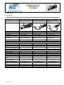
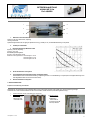
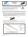
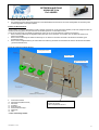
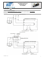
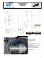
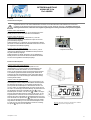
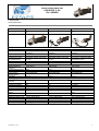
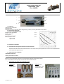
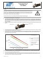
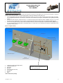
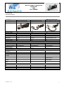
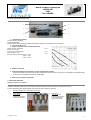
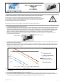
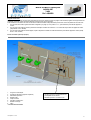
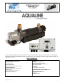
BETRIEBSANLEITUNG
AQUALINE 3 Kw
Ref. AQWRS
Mit dem Aqualine Heizsystem können Tränkelinien im Winter frostfrei gehalten werden und es garantiert so die regelmäßige
Versorgung von Tieren mit temperiertem Wasser. Aqualine kann an jede Tränkelinie für Rinder, Schafe, Schweine, Pferde usw.
angeschlossen werden.
INHALTSVERZEICHNIS
1. WICHTIGE SICHERHEITSANWEISUNGEN
Zu Ihrer Sicherheit: Seite 2
2. TECHNISCHE DATEN
Technische Merkmale: Seite 3
Explosionsansicht Heizelement Aqualine 3 kW: Seite 4
3. MONTAGEANWEISUNGEN
Auspacken und Vorbereitung der Installation: Seite 4
Vorkehrungen: Seite 5
Anschluss an den Wasserkreislauf: Seite 5 & 6
Elektrische Anschlüsse: Seite 7 & 8
4. BETRIEB
Inbetriebnahme der Heizung: Seite 9
Einstellung der Wassertemperatur: Seite 9
Zurückstellen des Sicherheitsthermostaten: Seite 10
Durchflussschalter : Seite 10
5. STÖRUNGEN
Bei Schwierigkeiten, Problemen: Seite 10
6. ANWEISUNGEN ZUM SCHUTZ DER UMWELT: Seite 11
7. UMFASSENDE QUALITÄT: Seite 11
8. GARANTIE
Garantieklauseln: Seite 11
Last update 12 11 2013
1
BETRIEBSANLEITUNG
AQUALINE 3 Kw
Ref. AQWRS
Das vorliegende Dokument enthält die Anweisungen, die bei Montage und
Inbetriebnahme zu beachten sind. Es muss daher vom Installateur und vom
Benutzer aufmerksam gelesen werden. Nach erfolgter Installation
aufbewahren.
1. WICHTIGE SICHERHEITSANWEISUNG
Zu Ihrer Sicherheit
Qualifikation des Personals:
Nur qualifizierte Personen sind befugt, die Installation durchzuführen.
Gefahren bei Nichtbefolgung der Anweisungen:
Die Nichtbefolgung von Anweisungen kann schwerwiegende Konsequenzen für die Sicherheit von Personen und Anlage haben und sogar zum Erlöschen
jeglicher Garantie führen. Unbedingte Befolgung wird vor allem hinsichtlich elektrischer Arbeiten und Installationsarbeiten verlangt.
Sicherheitshinweise für den Benutzer:
Befolgen Sie die Anweisungen, um jegliches Unfallrisiko auszuschließen.
Vermeiden Sie Gefahren durch elektrischen Strom unter Beachtung der Vorschriften der lokalen geltenden Norm.
Überprüfen Sie, ob Ihre Elektroinstallation durch eine Fehlerstromschutzeinrichtung geschützt ist und ob die Erdung den Vorschriften der lokalen geltenden
Norm entspricht oder lassen Sie dies von einer zugelassenen Prüfstelle kontrollieren.
Änderungen an der Anlage und Verwendung nicht zugelassener Einzelteile:
Änderungen an der Installation dürfen nur mit vorheriger Genehmigung des Herstellers durchgeführt werden. Die Verwendung von Originalteilen und
Zubehör, die/das vor Hersteller zugelassen sind/ist, gewährleistet die Sicherheit. Bei Verwendung anderer Teile übernimmt unser Unternehmen keine
Haftung.
Nicht zulässige Arten der Verwendung:
Die Verwendung des gelieferten Materials ist ausschließlich für einen oder mehrere der in dieser Betriebsanleitung genannten Verwendungszwecke
vorgesehen. Mit dem Aqualine Heizsystem können Tränkelinien im Winter frostfrei gehalten werden und es garantiert so die regelmäßige Versorgung von
Tieren mit temperiertem Wasser. Aqualine kann an jede Tränkelinie für Rinder, Schafe, Schweine, Pferde usw. angeschlossen werden.
.
Last update 12 11 2013
2
BETRIEBSANLEITUNG
AQUALINE 3 Kw
Ref. AQWRS
2. TECHNISCHE DATEN
Technische Merkmale
AQWRS 5023013000M
AQWRS 5023013000M +CB
AQWRS 5023013000M +CBD
Aqualine 3000W ohne Steuerung
Aqualine 3000W mit Steuerung
Aqualine 3000W mit digitaler
Steuerung
Heizkörper
Tauchheizkörper
Umlaufpumpe
Steuerung
Messung und Kontrolle der
Temperatur
Edelstahl
Abschirmung Incoloy 800®.
WILO Star Z 25/6
Nein
Einstellbarer
Kapillarthermostat 0° – 40°C
Edelstahl
Abschirmung Incoloy 800®.
WILO Star Z 25/6
Ja
Einstellbarer
Kapillarthermostat 0° – 40°C
Sicherheitsthermostat
Durchflussmesser
65°C mit manueller Reset
Nein
65°C mit manueller Reset
Nein
Edelstahl
Abschirmung Incoloy 800®.
WILO Star Z 25/6
Ja
PTC Sonde + digitaler
Regelthermostat
10 – 25°C
65°C mit manueller Reset
Ja
230V–50 Hz
IP44
3000 W/230V
49/74/99W/230V
230V–50 Hz
IP44
3000 W/230V
49/74/99W/230V
230V–50 Hz
IP44
3000 W/230V
49/74/99W/230V
13,5 A
13,5 A
13,5 A
6 bars (90 psi)
40 °C
Nein
Einstellbar von 0 bis 40°C
Nein
Kein Durchflussschalter
6 bars (90psi)
40 °C
Nein
Einstellbar von 0 bis 40°C
Nein
Kein Durchflussschalter
Nein
Nein
6 bars (90psi)
30°C
°C mit 0,1
Einstellbar von 10 bis 25°C
Unter 5°c und über 30°C
Durchflussschalter 6 L/min
max.
Ja
L410 x H160 x B110
L410 x H160 x B110
L410 x H160 x B110
Nein
8,9
Anschlüsse G 3/4"
L130 x H90 x B90
9,1
Anschlüsse G 3/4"
L250 x H200 x B130
11,2
Anschlüsse G 3/4"
MODELL
Beschreibung
Foto
Herstellungsmerkmale
Elektrische Merkmale
Stromversorgung
IP Schützung
Leistung/Spannung
Leistung Umlaufpumpe 3
Geschwindigkeiten/Spannung
Nennstrom
Betriebliche Merkmale
Max. Betriebsdruck
Höchsttemperatur
Temperaturanzeige
Solltemperatur
Grenzwert akustischer Alarm
Mindestflussmenge zum
Heizen
Akustischer Alarm bei
geringem Durchfluss
Allgemeine Eigenschaften
Abmessungen des Geräts in
mm
Abmessungen Gehäuse
Gewicht in kg
Wasseranschluss
Last update 12 11 2013
3
BETRIEBSANLEITUNG
AQUALINE 3 Kw
Ref. AQWRS
Explosionsansicht Heizelement Aqualine 3 kW
1
4
2
5
3
6
1. Elektrisches Tauchheizelement
Spannung: 230 VAC, Wechselstrom, einphasig.
Leistung: 3000 Watts.
Spiralenförmiges Element mit sehr geringer spezifischer Ladung (7,5 Watt pro cm²) und Edelstahlabschirmung Incoloy 800®.
2.
Heizkörper aus Edelstahl
3. Nassläuferumlaufpumpe WILO Star Z 25/6
Spannung: 230 VAC, Einphasig
Frequenz: 50 Hz (CE)
Drei Betriebsgeschwindigkeiten.
Durchfluss siehe beigefügte Tabelle
Elektrische Leistungsaufnahme Geschwindigkeit 1: 49 W
Geschwindigkeit 2: 74 W
Geschwindigkeit 3: 99 W
4.
Grosse Schutzhaube aus Polyamid
5.
Thermostatplatte mit Sicherheitsthermostat und Regelthermostat
Sicherheitsthermostat mit manueller Rückstellung, Temperaturgrenze 65°C und Schaltleistung 25 A (bei Aqualine mit digitaler Steuerung durch
einen Digitalthermostaten und einen PTC-Fühler ersetzt).
6.
Kleine Schutzhaube aus Polyamid
3. MONTAGEANWEISUNGEN
Auspacken und Vorbereitung der Installation
Überprüfen Sie, ob die Verpackung das komplette Zubehör und die nachfolgend genannten Teile enthält, bevor Sie die Verpackung entsorgen.
Verwenden Sie für eine korrekte Installation die Teile und das Zubehör, die/das mit dem Aqualine Gerät geliefert wurde(n).
1.
2.
Aqualine Heizsystem (mit oder ohne Steuerung, je nach Version)
Anschlusssatz
1 Rückschlagventil
3 Überdruckventil
1 Sicherheitsventil
3. Befestigungssatz
2 Aluminiumwinkel
4 Silent-Blocs
M6x15 / M6x10
4 Sechskantmuttern M6
4 Monoclip-Stifte M8
Last update 12 11 2013
4
BETRIEBSANLEITUNG
AQUALINE 3 Kw
Ref. AQWRS
Vorkehrungen
Die Installation muss von einem zugelassenen Techniker unter Befolgung der Montageanweisungen des Herstellers durchgeführt werden.
Der Wasserzulauf, sowie alle Wasserleitungen müssen unbedingt korrekt isoliert werden (mindestens 10
mm), um Wärmeverlust nach Möglichkeit zu vermeiden. Die Inbetriebnahme des Aqualine ist verboten,
wenn ein Teil der Wasserleitungen der Anlage eingefroren ist. Vor Inbetriebnahme des Geräts muss
überprüft werden, ob das Wasser in den Leitungen in flüssigem Zustand ist.
Anschluss an den Wasserkreislauf (für eine korrekte Installation verwenden Sie das Schema auf der folgenden
Seite)
1.
2.
3.
Das Aqualine Gerät muss unbedingt in waagerechter Position mittels des mitgelieferten Befestigungssatzes montiert werden, wie auf dem Foto unten
gezeigt.
Das Aqualine Gerät muss in einem gut isolierten Raum (frostfrei) vor Witterungseinflüssen und Feuchtigkeit geschützt installiert werden. Die
Wasserversorgung des Geräts muss unbedingt auch vor Frost geschützt werden. Sie darf auf keinen Fall einfrieren, da es sonst zu Wassermangel im
Gerät kommen kann, was zu schweren Fehlfunktionen des Geräts führen kann. Um Fehler bei der Wasserversorgung zu vermeiden, wird empfohlen,
einen Wasserdurchfluss-Anzeiger zu installieren (nicht im normalen Lieferumfang des Aqualine enthalten), um das Gerät bei Problemen außer
Betrieb nehmen zu können. Das Aqualine Gerät mit digitaler Steuerung ist mit einem Durchflussschalter ausgestattet, der einen Alarm auslöst und
den Widerstand unterbricht, wenn kein Wasserfluss vorhanden ist (weniger als 6 L/Min.).
Um den Anschluss an Rohre zu erleichtern, sind die Zulauf- und Ablaufverbindungen mit Schraubanschlüssen ¾ " versehen. Achten Sie darauf, dass
alle Anschlüsse vollkommen dicht sind.
Wasserzulauf G 3/4”
Wasserablauf G 3/4”
4.
Das Aqualine Gerät sollte vorzugsweise oberhalb des Niveaus der Tränkebecken installiert werden, um die Entlüftung zu erleichtern. Außerdem
müssen Entlüfter an den hoch gelegenen Stellen des Verteilungsnetzes installiert werden.
5.
Wählen Sie die Position so, dass die Länge der Leitungen nach Möglichkeit begrenzt werden kann und verwenden Sie vorzugsweise PE-Rohr mit 32
mm Durchmesser (Innendurchmesser mindestens 25 mm). Vermeiden Sie Knie und Verkürzungen im Kreislauf. Länge und maximale Anzahl der
Tränkebecken können mittels des folgenden Schemas ermittelt werden:
Die Daten gelten für eine Außentemperatur
von -20°C und eine Wassertemperatur von
10°C.
Rohrleitungslänge Polyethylen
isoliert
Rohrleitungslänge verzinkter Stahl
isoliert
Länge in m
Rohrleitungslänge Polyethylen
nicht isoliert
Rohrleitungslänge verzinkter Stahl
nicht isoliert
Anzahl der Tränkebecken
Bei –20°C, reguliert Aqualine das Wasser in Tränken auf circa 10°C auf einen isolierte Polyäthylen-Röhrenanlage von Maximum 250m.
6.
Eventuelle Abzweigungen am Kreislauf zum Anschließen von Tränkebecken müssen möglichst kurz sein, um die nicht rezirkulierte und daher nicht
erwärmte Wassermenge zu verringern.
Last update 12 11 2013
5
BETRIEBSANLEITUNG
AQUALINE 3 Kw
Ref. AQWRS
7.
8.
Die Verwendung eines Filters wird dringend empfohlen, um Verschmutzungen von Pumpe und Heizelement zu verhindern (vor allem, wenn das
Wasser aus einem Brunnen stammt).
Der empfohlene maximale Wasserdruck beträgt 6 bar. Ein Sicherheitsüberdruckventil mit 6 bar wird mit dem Gerät geliefert. Die Verwendung eines
Ausdehnungsgefäßes wird dringend empfohlen.
Entlüften des Wasserkreislaufs:
Um den Kreislauf vor der ersten Inbetriebnahme korrekt zu entlüften, überprüfen Sie, ob alle automatischen Entlüfter (an allen hoch gelegenen Punkten der
Installation positioniert) geöffnet sind (den Verschluss zwei Umdrehungen lösen, um den Entlüfter zu öffnen).
Lassen Sie die Umlaufpumpe (ohne Betrieb des Heizelements) laufen, bis die noch im Wasserkreislauf vorhandene Luft entfernt ist
1. Bei der Version ohne Steuerung den Regelthermostaten (siehe Seite 10) auf die Position "0°C" einstellen, dann den Stecker des Geräts an die
Steckdose anschließen.
2. Bei der Version mit Steuerung den Schalter der Steuerung auf "off" stellen und den Stecker des Geräts an die Steckdose anschließen (grüne
Kontrollleuchte brennt)
3.
Bei der Version mit digitaler Steuerung den Trennschalter in der Steuerung ausschalten und den Stecker des Geräts an die Steckdose anschließen
(grüne Kontrollleuchte brennt)
Schema der hydraulischen Installation (Beispiel)
Nicht geheizter Raum
Geheizter Raum
Fehlerstromschutzschalt
er
9. Automatischer Entlüfter
10. Sicherheitsventil (Überdruckventil)
11. Manometer *
12. Kugelhahn *
13. Rückschlagventil
14. Wasserdurchflussanzeiger *
15. Ablasshahn *
16. Filter *
* nicht im Lieferumfang enthalten
Bypass-Kreislauf für den Betrieb ohne
Einsatz des Aqualine.
Nur für Temperaturen über 10°C
Last update 12 11 2013
6
BETRIEBSANLEITUNG
AQUALINE 3 Kw
Ref. AQWRS
Elektrische Anschlüsse
Anschluss an 230 V Wechselstrom einiphasig.
Verwenden Sie einen 20 mA Fehlerstromschutzschalter und eine Erdung gemäß den geltenden Regelungen. (OBLIGATORISCH)
Schaltschemata
Aqualine ohne Steuerung
Aqualine mit Steuerung
Last update 12 11 2013
7
BETRIEBSANLEITUNG
AQUALINE 3 Kw
Ref. AQWRS
POWER ON HEATING
Buzzer
LOW FLOW
Heizelement
230VAC
Energieversorgung
Pumpe
PUMPE
DurchflussSchalter
3kW
SichereitsHeizelement Thermostat
Regulierungsth
ermostat
Summer /
Winter
230 VAC
Energieversorgung
DurchflussSchalter
Aqualine mit digitaler Steuerung
Thermostat
Energieversorgung
Carlor Engineering
Avenue Albert 1er, 87
4030 Grivegnée
30/07/2012
Identification n°:
AQWRS5023013000M+CBD
Bild innerhalb des digitalen Kontrollkastens
1 und 2: Stromversorgung 230V Wechselstrom
Phase + Nullleiter.
3 und 4: Anschluss an Schütz.
Buzzer
5 und 6: Durchflussschalter.
7 und 8: Pumpe.
9 und 10: Heizelement und Sicherheitsthermostat.
P: Schütz Heizelement
C2A: Magnetisch-thermischer Trennschalter für
Durchflussschalter Digitalthermostat.
1 2
3 4
5 6
7 8
9 10
P
C2A
P1
P1: Leistungsrelais für Durchflussschalter.
Summer: Verzögerter akustischer Alarm des
Durchflussschalters.
Last update 12 11 2013
8
BETRIEBSANLEITUNG
AQUALINE 3 Kw
Ref. AQWRS
4. BETRIEB
Inbetriebnahme des Heizgeräts
Vergewissern Sie sich vor der ersten Inbetriebnahme des Geräts, dass der Wasserkreislauf korrekt entlüftet wurde und dass Ihre
Installation mit allen elektrischen Sicherungseinrichtungen versehen ist (siehe "elektrischer Anschluss"). Ihr Aqualine Gerät muss in
Betrieb genommen werden, sobald die erste Frostgefahr angekündigt wird und den ganzen Winter über permanent eingesetzt
Aqualine, Version ohne Steuerung
Sobald der Stecker angeschlossen wird, wird die Umlaufpumpe sofort in
Betrieb genommen und der Thermostat steuert das Heizelement.
Aqualine, Version mit Steuerung
Sobald der Stecker angeschlossen wird (Position "0"), nimmt die
Umlaufpumpe ihren Betrieb auf. Der Betrieb der Pumpe wird durch die
grüne Kontrolllampe angezeigt.
Sobald der Schalter auf "1" gestellt wird, wird das Heizelement in Betrieb
genommen und erwärmt das Wasser. Der Betrieb des Elements wird durch
die orangefarbene Kontrolllampe angezeigt.
Schalter ON/OFF
Grüne Kontrolllampe
Orangefarbene Kontrolllampe
Aqualine, Version mit digitaler Steuerung
Sobald der Stecker angeschlossen wird (Position "Summer"), wird die
Umlaufpumpe in Betrieb genommen. Der Betrieb der Pumpe wird durch
die grüne Kontrolllampe angezeigt.
Sobald der Schalter auf "Winter" gestellt wird, wird das Heizelement in
Betrieb genommen und erwärmt das Wasser. Der Betrieb des Elements
wird durch die orangefarbene Kontrolllampe angezeigt.
Einstellen der Wassertemperatur
Aqualine, Version ohne und mit Steuerung
Der Regelthermostat begrenzt die Wassertemperatur auf 15°C
(Werkseinstellung). Es ist jedoch möglich, die Einstelltemperatur des
Thermostaten innerhalb eines Bereichs von 0 bis 40°C manuell zu
ändern. Um die Temperatur zu ändern, lösen Sie den Schraubverschluss
an der seitlichen großen Schutzhaube des Heizgeräts. Stellen Sie die
Temperatur mit einem Schraubendreher auf den gewünschten Wert ein.
Der Schutzstopfen muss nach Einstellung des Thermostaten unbedingt
wieder angebracht werden.
Aqualine, Version mit digitaler Steuerung
Der elektronische Regelthermostat erlaubt eine genauere Steuerung der
Wassertemperatur und eine Anzeige der tatsächlichen Wassertemperatur.
Der Thermostat wird im Werk auf 15°C eingestellt, der Benutzer kann
jedoch jederzeit die Einstelltemperatur in einem Bereich zwischen 10°C
und 25°C ändern. Um die Einstelltemperatur zu ändern, drücken Sie kurz
die Taste P. Auf dem Display erscheint die Meldung "SP" abwechselnd mit
dem Einstellwert. Drücken Sie anschließend die Taste " ", um die
Einstelltemperatur zu erhöhen, oder die Taste " ", um die zu verringern.
Wenn der gewünschte Wert erreicht ist, drücken Sie die Taste P, um den
Programmiermodus zu beenden. Es wird automatisch beendet, wenn 10
Sekunden lang keine Taste betätigt wird. Der Regelthermostat ist auch mit
einem akustischen und optischen Alarm 1 ausgestattet, der den Benutzer
warnt, wenn die Wassertemperatur anormale Werte erreicht. Das Display
zeigt außerdem die Meldung "Lo" ein, wenn die Wassertemperatur unter
5°C sinkt oder "Hi", wenn die Wassertemperatur auf über 30°C ansteigt.
Das Symbol 2 zeigt an, dass das Gerät heizt.
1
2
Hinweis: die Taste U dient zum Anzeigen der variablen
Parameter (gemessene Temperatur usw.)
Last update 12 11 2013
9
BETRIEBSANLEITUNG
AQUALINE 3 Kw
Ref. AQWRS
Zurückstellen des Sicherheitsthermostaten
Bei Überhitzung aufgrund mangelnder Wasserzufuhr oder aufgrund eines
elektrischen Problems löst der Sicherheitsthermostat aus und unterbricht die
Stromversorgung des Heizelements. Nach Überprüfung des Systems und Lösung
des Problems muss der Sicherheitsthermostat manuell zurückgestellt werden.
Lösen Sie dazu den Schraubverschluss an der Seite der Heizung und stellen Sie
den Sicherheitsthermostaten zurück Beim Aqualine digital müssen Sie den
Schraubverschluss an der seitlichen großen Schutzhaube des Heizgeräts
entfernen, um den Sicherheitsthermostaten zu erreichen.
Durchflussschalter (nur bei Aqualine mit digitaler Steuerung)
Bei unzureichendem Wasserdurchfluss (weniger als 6l/min) unterbricht der Durchflussmesser die Stromversorgung des Heizelements und löst den Alarm,
sowie die rote Kontrolllampe (LOW FLOW) aus. Wenn der Wasserdurchfluss wieder normal wird (mehr als 6l/Min), schaltet der Durchflussschalter den
Widerstand wieder ein und deaktiviert den Alarm, sowie die rote Kontrolllampe. Wenn der Alarm ausgelöst wurde, muss überprüft werden, ob das Aqualine
Gerät mit Wasser versorgt wird und ob die Zirkulation im Kreislauf möglich ist (kein Eispfropfen oder Verunreinigungen vorhanden).
5. STÖRUNGEN
Bevor Sie den technischen Kundendienst anrufen, verfahren Sie bitte nach der folgenden Tabelle:
Fehler
Das Heizelement des Aqualine und
das Wasser in den Tränkebecken
bleiben kalt.
Die Stromversorgung ist korrekt, aber
das Heizelement des Aqualine und
die Tränkebecken bleiben kalt.
Mögliche Ursachen
- Das Aqualine Gerät wird nicht mit
Strom versorgt.
- Der Sicherheitsthermostat wurde
aufgrund einer Überhitzung des
Heizelements ausgelöst, die auf
Luftblasen im Wasserkreislauf
zurückzuführen sind
- Heizelement oder Thermostat
defekt
Der Wasserkreislauf ist gefüllt und
- Mangelnde Wasserzirkulation
entlüftet, das Aqualine Gerät ist
- Pumpe durch Verunreinigungen
warm, aber die Tränkebecken bleiben oder Ablagerungen blockiert.
kalt.
- Ausfall der Pumpe.
Sicherung oder Schutzschalter im
Verteilerkasten lösen aus.
- Elektrische Störung beim Aqualine
Gerät
Kontrolle & Abhilfen
3. Den Anschluss des Versorgungskabels überprüfen
4. Die Elektroinstallation überprüfen (Schaltautomaten, Sicherungen…)
4. Die Wasserversorgung überprüfen und vergewissern, dass das Wasser
in den Leitungen läuft.
5. Die einwandfreie Funktion des Entlüfters überprüfen und vergewissern,
dass keine Luft im Kreislauf vorhanden ist.
6. Den Sicherheitsthermostaten zurückstellen (siehe Verfahren oben)
5. Überprüfen, ob das Wasser in den Leitungen läuft.
6. Überprüfen, ob das Wasser in den Leitungen sauber ist und keine
Feststoffe enthält (Filter installieren, wenn dies nicht der Fall ist).
7. Vergewissern, dass die Pumpe auf Stufe 3 läuft.
8. Die Pumpe befreien, wenn sie blockiert ist.
3. Das Speisekabel vom Netz trennen.
4. Das Aqualine Gerät außer Betrieb nehmen und den technischen
Kundendienst rufen
Nur für Aqualine mit digitaler Steuerung
Fehler
Der digitale Thermostat
löst akustischen Alarm
aus und zeigt die
Meldung "Lo" an
Der digitale Thermostat
löst akustischen Alarm
aus und zeigt die
Meldung "Hi" an
Der Summer wird
ausgelöst und die rote
Lampe "LOW FLOW"
leuchtet auf
Mögliche
Ursachen
Die Wassertemperatur
liegt unter
5°C
Die Wassertemperatur
liegt über
30°C
Der
Wasserdurc
h-fluss im
Versorgungs
-kreislauf ist
zu gering
Kontrolle & Abhilfen
Das Aqualine Gerät
kann kein Wasser
erwärmen
Thermostat defekt
- Die Leitungen sind zu
lang
- Die Komponenten des
Kreislaufs hemmen die
Zirkulation
- Ein Eis- oder
Schmutzpfropfen hat
sich gebildet
Fehler
4. Prüfen, ob die Leitungen korrekt isoliert sind (zu starker Wärmeverlust)
5. Das Heizelement auf einwandfreie Funktion überprüfen (Gehäuse des Aqualine
Geräts warm)
6. Stromversorgung des Aqualine unterbrechen und die Leitungen leeren, um sie vor
Frost zu schützen.
3. Einwandfreie Funktion des Thermostaten überprüfen
4. Aqualine außer Betrieb nehmen und den technischen Kundendienst verständigen
6. Bei der ersten Inbetriebnahme ist eine Verzögerung von einigen Minuten möglich,
bevor die Zirkulation tatsächlich erfolgt.
7. Vergewissern Sie sich, dass die Länge des Kreislaufs die Werte im Schema auf
Seite 6 nicht überschreitet.
8. Vergewissern Sie sich, dass nicht zu viele Anschlüsse, Knie oder Tränkebecken
vorhanden sind und dass sie einen ausreichenden Durchflussdurchmesser haben.
9. Überprüfen Sie, ob die Leitungen verstopft sind.
10. Fügen Sie in der Mitte der Anlage eine Umlaufpumpe oder ein zweites Aqualine
Gerät hinzu.
Last update 12 11 2013
10
BETRIEBSANLEITUNG
AQUALINE 3 Kw
Ref. AQWRS
6. ANWEISUNGEN ZUM SCHUTZ DER UMWELT
Rückgewinnung von Rohmaterialien statt Abfallentsorgung
Die Geräte, sowie Zubehör und Verpackungen, müssen auf geeignete Weise recycelt werden.
Unsere Teile können nach Trennung der Materialien ebenfalls selektiv recycelt werden.
Carlor Engineering verpflichtet sich, die verschiedenen Bestandteile des Aqualine Geräts zu recyceln.
Jedes Aqualine Gerät kann auf Wunsch des Kunden überholt oder selektiv recycelt werden.
7. UMFASSENDE QUALITÄT
Jedes Gerät der Marke Aqualine wird beim Verlassen des Werks kontrolliert und getestet. Daher kann eine Restmenge Wasser im Heizelement vorhanden sein.
Carlor Engineering führt folgende Tests an jedem Aqualine Gerät durch:
•
•
•
•
•
Test der elektrischen Isolierung.
Heiztest
Funktionsprüfung der Umlaufpumpe
Dichtigkeitsprüfung des Heizelements unter Druck.
Funktionsprüfung des Regelthermostaten.
In der Verpackung finden Sie ein Blatt mit allen durchgeführten Tests. Bewahren Sie dieses Blatt auf.
8. GARANTIE
Garantieklauseln
Auf Aqualine-Geräte wird eine Garantie von zwei Jahren ab dem Rechnungsdatum in Bezug auf Konstruktionsmängel gewährt.
Diese Garantie gilt in folgenden Situationen nicht:
•
Das Gerät wurde ohne Genehmigung seitens Carlor Engineering verändert.
•
Installation und Betrieb entsprechen nicht den Anweisungen in der Betriebsanleitung des Aqualine Geräts.
•
Partikel oder Verunreinigungen verursachten Schäden am Gerät.
2 Jahre Garantie auf Teile und Verarbeitung. Laut unseren allgemeinen Geschäftsbedingungen. Unsere Garantie deckt
ausschließlich den normalen Austausch des Geräts oder den Ersatz defekter Teile. Versandkosten und die Kosten für die
Installation der Heizung werden nicht von Carlor Engineering übernommen.
Hergestellt in Belgien von:
Carlor Engineering S.A.
Avenue Albert 1er, 87
B-4030 Grivegnée
Belgien
Tel: +32 4 384 01 97 Fax: +32 4 367 16 66
[email protected] www.carlor.com
Carlor Engineering S.A.
er
Avenue Albert 1 , 87
Tél. : +32 (0)4 384 01 97
www.carlor.com
B-4030 Grivegnée
Belgique
Fax : + 32 (0)4 367 16 66
[email protected]
Last update 12 11 2013
11
USER GUIDE ENGLISH
AQUALINE 3 Kw
Ref. AQWRS
The Aqualine is a heating and circulating unit for a line of drinking bowls. It ensures the supply of temperate drinking water in
winter time and prevents the water from freezing in the tubes. It can be connected to any drinking bowl line for cows, calves,
sheep, pigs, horses, etc.
TABLE OF CONTENTS
1. IMPORTANT SAFETY INSTRUCTIONS
For your safety : page 2
2. SPECIFICATIONS
Technical characteristics : page 3
Exploded view Aqualine 3 kW: page 4
3. MOUNTING INSTRUCTIONS
Unpacking and installation preparation : page 4
Precautions : page 5
Connecting the water circuit : page 5 and 6
Electrical connections : page 7 and 8
4. DIRECTIONS FOR USE
Putting the heater into service : page 9
Regulating the water temperature : page 9
Resetting the safety thermostat : page 10
Flow switch : page 10
5. TROUBLESHOOTING
In case of difficulties : page 10
6. INSTRUCTIONS FOR THE PROTECTION OF THE ENVIRONMENT : page 11
7. TOTAL QUALITY : page 11
8. WARRANTY AND SERVICE
Warranty clauses : page 11
Last update 12 11 2013
1
USER GUIDE ENGLISH
AQUALINE 3 Kw
Ref. AQWRS
The present user’s guide contains instructions to be fulfilled during the
mounting and the starting stage. It should be read carefully by the
technician and the user. Keep these instructions after installation.
1. IMPORTANT SAFETY INSTRUCTIONS
For your safety
Qualified personnel
The mounting should be carried out by a qualified technician only.
Danger in case of non-compliance with the present guidelines
The non-compliance with present guidelines could have serious consequences for the safety of people and could damage the equipment, thus making the
warranty void. The strictest rigor is required for the electrical and mechanical aspects of the mounting.
Safety measures meant for the user
Avoid any risks linked to the mains network by strictly observing local safety instructions in force.
Check or have checked by an authorized technician that your electrical installation is protected by a differential current system and that the ground is in
compliance with the local safety prescriptions.
Modifications to the heater and use of unauthorized parts
Any modification to the heater will be made only in agreement with the manufacturer. The use of official spare parts and accessories guarantees your
safety. The manufacturer disclaims any liability in case non-original parts are used.
Inappropriate use of the equipment
The Aqualine supplied is exclusively meant for the applications described in this user guide. The Aqualine is a heating and circulating unit for a line of
drinking bowls. It ensures the supply of temperate drinking water in winter time and prevents the water from freezing in the tubes. It can be connected to
any drinking bowl line for cows, calves, sheep, pigs, horses, etc.
.
Last update 12 11 2013
2
USER GUIDE ENGLISH
AQUALINE 3 Kw
Ref. AQWRS
2. SPECIFICATIONS
Technical characteristics
MODEL
Description
AQWRS 5023013000M
AQWRS 5023013000M +CB
AQWRS 5023013000M +CBD
Aqualine 3000W without control
box
Aqualine 3000W with control box
Aqualine 3000W with digital control
box
Stainless steal
Incoloy 800® Stainless steel
protection
WILO Star Z 25/6
yes
Adjustable capillary thermostat
0°-40°c
65°C with manual reset
no
Stainless steal
Incoloy 800® Stainless steel
protection
WILO Star Z 25/6
yes
PTC sensor + digital regulation
thermostat 10 -25°c
65°C with manual reset
yes
230V–50 Hz
230V–50 Hz
230V–50 Hz
IP44
3000 W/230V
49/74/99W/230V
IP44
3000 W/230V
49/74/99W/230V
IP44
3000 W/230V
49/74/99W/230V
13,5 A
13,5 A
13,5 A
6 bars (90 psi)
6 bars (90psi)
6 bars (90psi)
40 °C
No
Adjustable from 0 to 40°C
No
No flow switch
40 °C
No
Adjustable from 0 to 40°C
No
No flow switch
No
No
30°C
°C with 0,1
Adjustable from 10 to 25°C
Below 5°c and above 30°C
Flow switch with a limit at 6
l/min
Yes
L410 x H160 x D110
L130 x H90 x D90
9,1
G3/4" nipples connections
L410 x H160 x D110
L250 x H200 x D130
11,2
G3/4" nipples connections
Picture
Components characteristics
Heating body
Heating coil
Circulation pump
Control box
Temperature control
and measurement
Safety thermostat
Flow Switch
Stainless steal
Incoloy 800® Stainless steel
protection
WILO Star Z 25/6
no
Adjustable capillary thermostat
0°-40°c
65°C with manual reset
no
Electrical characteristics
Rated voltage and
frequency
Ingress protection level
Power/Voltage
Pump power 3
speeds/voltage
Amperage
Working specifications
Maximum working
pressure
Maximum temperature
Temperature display
Temperature range
Temperature alarm limit
Minimum flow for
heating
Low flow alarm buzzer
General characteristics
Dimensions body in mm
Dimensions control box
Weight in kg
Water connections
Last update 12 11 2013
L410 x H160 x D110
Non
8,9
G3/4" nipples connections
3
USER GUIDE ENGLISH
AQUALINE 3 Kw
Ref. AQWRS
Exploded view Aqualine 3 kW
1
4
2
5
3
6
1. Heating coil
Voltage: 230 VAC, single-phase.
Power: 3000 Watts.
Heating element formed in spiral with ultra low wattage density (7,5 W/cm²) and Incoloy 800® stainless steel protection
2. Stainless steel heating body
3. Wet rotor pump WILO Star Z 25/6
Speed 3
Voltage: 230 VAC, single phased
Frequency: 50 Hz (CE)
Speed 2
3 running speed.
Flow rate in the enclosed table
Power input speed 1 : 49W
Speed 1
speed 2 : 74W
speed 3 : 99 W
4. Support base in Polyamide.
5. Thermostatic plate with regulation thermostat and safety thermostat
Safety thermostat with manual reset, temperature limit at 60°c and 25 Amps cutting capacity (replaced by a PTC sensor and a digital thermostat
on the Aqualine with digital control box)
6. Large protection cap in polyamide
3. MOUNTING INSTRUCTIONS
Unpacking and installation preparation
Make sure you have the following components and accessories before disposing of the packaging material:
For a correct installation use the spare parts and accessories delivered with the Aqualine.
1.
Heater Aqualine (with or without control box depending the model)
2.
Connection kit
1 Antireturn valve
1 Overpressure valve
3 Air bleed valve
Last update 12 11 2013
3.
Fixation kit
2 aluminum brackets
4 Silent blocs M6x15 / M6x10
4 screws M 6
4 fixation screws pin M8
4
USER GUIDE ENGLISH
AQUALINE 3 Kw
Ref. AQWRS
Precautions
The installation must be made by an authorized technician in strict compliance with the instructions of the manufacturer.
The water supply and all the pipes must be correctly insulated (10mm minimum) to avoid heat dissipation. It is strictly
prohibited to let the Aqualine in use when any part of the water circuit is frozen. It should be carefully checked that the
water in the pipes is in liquid state, before starting the installation.
Connecting the water circuit (for a correct installation, please refer to the diagram on the following page)
1.
2.
3.
It is compulsory to install the Aqualine in a horizontal position.
The Aqualine should be installed in a place well protected from bad weather conditions and humidity. It is compulsory that the water supply of the
device is also protected from freezing. The water supply cannot freeze under no circumstances as a lack of water would lead to great damages of the
heater. In order to prevent a failure due to water supplying, it is recommended to use a water flow indicator (not delivered with the standard Aqualine).
The Aqualine with digital control box is equipped with a flow switch that turns on an alarm and turns off the heating element in case of no flow (under
6l/min) into the tubing.
In order to facilitate the connection of the pipes, in and out connectors are supplied with ¾” nipples connections. Make sure the connections are well
tightened
Entrée d’eau G 3/4”
Sortie d’eau G 3/4”
4.
5.
The Aqualine will preferably be installed above the level of the drinking bowl in order to facilitate the purge of the water circuit. In addition, it is needed
to install air bleed valves on all the high points of the water circuit.
Choose a position in order to decrease as much as possible the length of the connecting pipes and preferably use 25mm diameter PE tubing (20 mm
inside diameter). Avoid as much as possible elbows and reductions on the circuit. The length and the maximum number of drinking bowls can be
determined with the help of the diagram below:
Valid for an outside temperature of -20°c
and a water temperature of 10°c.
Length for insulated polyethylene
tubing
Length for insulated steel tubing
Length in
meters
Length for non insulated
polyethylene tubing
Length for non insulated steel
tubing
Number of drinking bowls
For an environmental temperature of -20°C, the Aqualine keeps the water in the drinking bowls at 10°C on a maximum tubing length of 250 m.
6.
7.
8.
It is not recommended to install T-connections on the circuit.
It is very much recommended to install a filter in order to protect the pump and the heating coil from dirt (especially if the water comes from a well).
The maximum advised water pressure is 6 bars. A safety overpressure valve of 6 bars is delivered with the heater. Using an expansion tank is also
highly recommended so as to balance the pressure inside the tubes.
Last update 12 11 2013
5
USER GUIDE ENGLISH
AQUALINE 3 Kw
Ref. AQWRS
Purging the water circuit for the first start:
For purging the circuit before the first start, check that all the air-bleed valves (placed at each highest point of the circuit) are well opened. To open the
bleeders, unscrew the cap 2 rotations.
Start the circulator pump alone (without starting the heating element) until the air is eliminated from the water circuit:
1. For the version without control box, set the regulation thermostat (see page 10) on the 0°C position and then plug the power cable to the network.
You can regulate the thermostat to 15°C when you are sure that no air is inside the circuit anymore. The thermostat is now regulating the heating
element.
2. For the version with control box, set the switch on the « off » position and plug the power cable to the network (« GREEN » lamp is on). You can set
the switch on the “on” position when you are sure that no air is inside the circuit anymore. The thermostat is now regulating the heating element.
3. For the version with digital control box, switch off the circuit breaker inside the control box and plug the power cable to the network (“GREEN” lamp is
on). You can switch on the magneto-thermic circuit breaker when you are sure that no air is inside the circuit anymore. The thermostat is now
regulating the heating element.
Water circuit diagram (example)
1. Air bleed valve (placed at the highest points)
2. Overpressure safety valve
3. Manometer *
4. Ball valve *
5. Check valve (Anti-return valve)
6. Flow indicator *
7. Drain tap *
8. Filter *
* Not included into the package
Last update 12 11 2013
By-passing line for operating without
Aqualine! Only for temperatures above
+ 10C° in the cold room.
6
USER GUIDE ENGLISH
AQUALINE 3 Kw
Ref. AQWRS
Electrical connections
Connect to a 230 VAC single-phase circuit.
Use a 30 mA differential circuit breaker and ground according to the rules in force (MANDATORY)
Electrical diagram
Aqualine without control box
Aqualine with control box
Last update 12 11 2013
7
USER GUIDE ENGLISH
AQUALINE 3 Kw
Ref. AQWRS
POWER ON HEATING
Buzzer
LOW FLOW
Thermostat
Power Supply
Heating
Element
230VAC Power
Supply
Pump
PUMP
Flow switch
3kW heating
Safety
element
Thermostat
Regulation
thermostat
Summer /
Winter
230 VAC
Power supply
Flow switch
Aqualine with digital control box
Carlor: power scheme
Carlor Engineering
Avenue Albert 1er , 87
4030 Grivegnée
30/07/2012
Identification n°:
AQWRS5023013000M+CBD
Picture inside digital control box
1 and 2 : Power supply 230VAC Phase + Neutral.
3 and 4 : Connection to contactor.
Buzzer
5 and 6 : Flow switch.
7 and 8 : Pump.
9 and 10 : Heating element and safety thermostat.
P : Heating element contactor.
1 2
3 4
5 6
7 8
9 10
P
C2A
P1
C2A : 2 amps magnetothermic circuit breaker for
flow switch and digital thermostat.
P1 : Flow switch power relay.
Buzzer : Flow switch alarm buzzer.
Last update 12 11 2013
8
USER GUIDE ENGLISH
AQUALINE 3 Kw
Ref. AQWRS
4. DIRECTION OF USE
Putting the heater into service
Before putting into service the device, check that the water circuit is purged, and the installation obeys all security measures for the
electrical parts (see “electrical connections”). Your Aqualine must be started before risk of frost is announced and run continuously
throughout the winter.
Aqualine, without control box
As soon as the male plug is connected to the mains, the circulating
pump will be working and the thermostat governs the heating element.
Switch ON/OFF
Aqualine, with control box
As soon as the male plug is connected to the mains (position 0), the
circulating pump will be working. This is indicated by green lamp on
the control box.
When the switch on the control box is turned on 1, the heating element
is working. This is indicated by the orange lamp on the control box.
Aqualine, with digital control box
As soon as the male plug is connected to the mains (position
“summer”), the circulating pump will be working. This is indicated by
green lamp on the control box.
When the switch on the control box is turned on “Winter”, the heating
element is working. This is indicated by the orange lamp on the control
box.
Green lamp
Orange Lamp
Regulating the water temperature
Aqualine with or without control box
The regulating thermostat is set at the factory on 15°C. At the
installation, it is possible to modify the setting of the temperature
manually from 0°C to 40°C. To change the temperature setting, open
the screwplug located on the lateral cap of the heater. Use a
screwdriver to set the temperature on the required value. It is
imperative to fix again the protection cap after having regulating the
thermostat.
Aqualine with digital control box
The electronic regulation thermostat allows a better control of the water
temperature and gives a view of the real water temperature. The thermostat
is set at the factory at 15°c but the user can modify at all time the set point
between 10°c and 25°c. Press the key “P” then release it in order to modify
the temperature. The Display will show “SP” alternating with the set value.
To change it press the up key « » to increase the value or the down key
« » to decrease it. When the desired value is set press the key «P » to
exit from the temperature set point programming mode. The exit will be
achieved also automatically if no key is pressed for 10 second.
The regulation thermostat is also equipped with an alarm buzzer and a
visual Led alarm 1 that warns the user if the water temperature reaches
abnormal temperature. In addition, the display will show « Lo » if the water
temperature goes under 5°c and « Hi » if the water temperature goes
above 30°c. Led 2 indicates that the Aqualine is heating.
Last update 12 11 2013
1
2
Note : Key U is used (press and release) for visualising the
instrument variables (measured temperatures etc.)
9
USER GUIDE ENGLISH
AQUALINE 3 Kw
Ref. AQWRS
Resetting the safety thermostat
In case of overheating, the safety thermostat is activated and cut the
heating element and the pump. After having the system checked,
the safety thermostat has to be manually reset. In order to do this,
unscrew the screwplug on the bottom of the heater and push the
reset button. For the Aqualine with digital control box, you need to
unscrew the PG on the lateral cap of the heater to access the safety
thermostat.
Flow switch (only for the Aqualine with digital control box)
In case of insufficient flow (under 6l/min), the flow switch shuts down the heating element and activate an alarm and a red LED (LOW FLOW) on the control
box. If the water flow comes back to normal (above 6l/min), the flow switch will allow the heating again and it will shut down the alarm and the red LED. If
the alarm is activated, check that the Aqualine is still fed with water and that water can circulate through the circuit (no ice plug or dirt plug).
5. TROUBLESHOOTING
Before contacting the technical service, please check the following table for causes and remedies:
Type of problem
The Aqualine and the water in the
drinking bowls stay cold.
The connection to the mains is
correct. The Aqualine and the water
in the bowls remain cold.
The water supply is correct and
purged, the Aqualine is hot but the
drinking bowls stay cold.
The fuse or the circuit breaker in the
distribution box is engaged
Possible causes
- The Aqualine is not connected to
the mains.
- The safety thermostat has been
switched on because there is still
some air into the Aqualine
(overheating of the heating element)
-The heating element or the
regulating thermostat is not working.
- Bad water circulation.
- The circulating pump is blocked by
impurities.
- The pump is broken
- Electrical breakdown of the
Aqualine
3.
Control and remedies
Check that the supplying cable is connected to the mains.
Check that the supply to the mains is correct (fuses,...)
Check the water supply and make sure water is still flowing into the
tubing.
Make sure that the air-bleed valve is working properly and that no air
is trapped into the circuit anymore.
Reset the safety thermostat.
1.
2.
3.
4.
1.
2.
Make sure water flows into the tubing.
Check that the water in pipes is clean and without solid particles.
Make sure the pump is on speed 3.
Unblock the jammed pump.
Take off the supplying cable.
Put the Aqualine out of service and call the technical service.
1.
2.
1.
2.
Only for the Aqualine with digital control box
Defaults
The digital
thermostat rings
and displays
« Lo »
The digital
thermostat
digital rings and
displays « Hi »
The alarm
buzzer and the
LED “LOW
FLOW” are on
Reasons
The water
temperature is
under 5°c
Possible causes
The Aqualine cannot
heat up the water
The water
temperature is
above 30°c
The regulation
thermostat is broken
The water flow
into the water
circuit is too
low
-The water circuit is too
long.
- Too much elbows and
reductions on the circuit.
-An ice plug or a dirt
plug blocks the
circulation
Last update 12 11 2013
Controls & Remedies
1. Check that the water circuit is well insulated (the loss of heat is too important)
2. Make sure the heating element is properly working (the body of the Aqualine is hot)
3. Take off the supply cable of the Aqualine and empty the water tubing to protect them
from frost.
1. Check the thermostat is working properly
2. Put the Aqualine out of service and call the technical service.
1. If it is the first time you put the Aqualine into service, the pump may need a certain time
to create the circulation.
2. Make sure the length of the tubing is not longer than the maximum length mentioned in
the schematic page 5.
3. Avoid as much as possible elbows and reductions on the circuit. Inside diameter of the
connection should be the same as the tubing.
4. Check that no plug is blocking the tubing.
5. Add a circulation pump or a second Aqualine in the middle of the installation.
10
USER GUIDE ENGLISH
AQUALINE 3 Kw
Ref. AQWRS
6. INSTRUCTIONS FOR THE PROTECTION OF THE ENVIRONMENT
Recuperation of raw materials rather that elimination of waste
Machines, as well as their accessories and packaging, should be recycled in an appropriate way. Our spare parts can be recycled selectively depending on
the type of material. Carlor Engineering S.A. commits itself to recycle the different components of the Aqualine. Each Aqualine will be either reconditioned
or recycled selectively at the Customer’s request.
7. TOTAL QUALITY
Each Aqualine is controlled and tested before leaving the factory. For this reason, it is possible to find residual water in the heating body. Carlor
Engineering runs the following test on each Aqualine:
•
•
•
•
•
Test of electrical insulation
Test of heating capacity.
Test of the circulating pump
Water tightness pressure test of the heating body
Test of the regulating thermostat
You will find in the packaging a check list of all the tests undergone on your Aqualine. Keep this list carefully.
8. WARRANTY
All our devices « Aqualine » are guaranteed against all manufacturing errors over a 2 years period, starting at the invoice date. This warranty is voided in
each of the following situations
•
The device was transformed or modified without our permission of Carlor Engineering
•
Installation und use are against the guidelines listed in the present user guide.
•
No heaters will be repaired under warranty if it is proved that it is damaged by impurities or grimes.
Our warranty covers exclusively the changing of the standard installation or replacement of the damaged parts. Are not taken
under warranty: wrong installation or use, costs for assembling and disassembling the heater, costs for assembling or
disassembling the installation, shipment costs.
Manufactured in Belgium by:
Carlor Engineering S.A.
Avenue Albert 1er, 87
B-4030 Grivegnée
Belgique
Tel: +32 4 384 01 97 Fax: +32 4 367 16 66
[email protected] www.carlor.com
Carlor Engineering S.A.
er
Avenue Albert 1 , 87
Tél. : +32 (0)4 384 01 97
www.carlor.com
Last update 12 11 2013
B-4030 Grivegnée
Belgique
Fax : + 32 (0)4 367 16 66
[email protected]
11
MODE D’EMPLOI FRANÇAIS
AQUALINE
3 kW
Ref. AQWRS
Le réchauffeur Aqualine permet de mettre une ligne d’abreuvoirs hors gel en hiver et garantit ainsi un approvisionnement
régulier des animaux en eau tempérée. L’Aqualine peut être raccordé à toute ligne d’abreuvoirs pour vaches, veaux, moutons,
porcs, chevaux, etc.
TABLE DES MATIERES
1. INSTRUCTIONS DE SECURITE IMPORTANTES
Pour votre sécurité : page 2
2. SPECIFICATIONS
Caractéristiques techniques : page 3
Vue éclatée corps de chauffe Aqualine 3 kW : page 4
3. INSTRUCTIONS DE MONTAGE
Déballage et préparation de l’installation : page 4
Précautions : page 5
Raccordement au circuit d’eau : page 5 et 6
Raccordements électriques : page 7 et 8
4. FONCTIONNEMENT
Mise en service du réchauffeur : page 9
Réglage de la température de l’eau : page 9
Réarmement du thermostat de sécurité : page 10
Commutateur de débit : page 10
5. DERANGEMENTS
En cas de difficultés, problèmes : page 10
6. INSTRUCTIONS POUR LA PROTECTION DE L’ENVIRONNEMENT : page 11
7. QUALITE TOTALE : page 11
8. GARANTIE
Clauses de garantie : page 11
Last update 12 11 2013
1
MODE D’EMPLOI FRANÇAIS
AQUALINE
3 kW
Ref. AQWRS
La présente notice contient les instructions à respecter lors du montage et
de la mise en service. C’est pourquoi elle devra être lue attentivement par
l’installateur et l’utilisateur. A conserver après l’installation.
1. INSTRUCTION DE SECURITE IMPORTANTE
Pour votre sécurité
Qualification du personnel :
Seul un personnel qualifié est autorisé à effectuer l’installation.
Dangers encourus en cas de non observation des consignes :
La non observation des consignes peut avoir des conséquences graves sur la sécurité des personnes et de l’installation et peut même entraîner la
suspension de toute garantie. Une rigueur absolue est exigée notamment en matière d'électricité et de plomberie.
Conseils de sécurité à l’utilisateur :
Observer les consignes en vue d’exclure tout risque d’accident.
Eviter les dangers dus au réseau électrique en respectant les prescriptions de la norme locale en vigueur.
Veiller à vérifier ou à faire vérifier par un organisme agréé, que votre installation électrique est bien protégée par un dispositif à courant différentiel résiduel
et que la prise de terre est correcte suivant le respect des prescriptions de la norme locale en vigueur.
Modifications du matériel et usage de pièces détachées non agréées :
Toute modification de l’installation ne peut être effectuée qu’après l’autorisation préalable du fabricant. L’utilisation de pièces de rechange d’origine et
d’accessoires autorisés par le fabricant garantit la sécurité. L’usage d’autres pièces peut dégager notre société de toute responsabilité.
Modes d’utilisation non autorisés :
L’utilisation du matériel livré est prévue exclusivement pour une ou des applications précisées dans ce mode d’emploi. Le réchauffeur Aqualine permet de
mettre une ligne d’abreuvoirs hors gel en hiver et garantit ainsi un approvisionnement régulier des animaux en eau tempérée. L’Aqualine peut être
raccordé à toute ligne d’abreuvoirs pour vaches, veaux, moutons, porcs, chevaux, etc.
Last update 12 11 2013
2
MODE D’EMPLOI FRANÇAIS
AQUALINE
3 kW
Ref. AQWRS
2. SPECIFICATIONS
Caractéristiques techniques
MODELE
Description
Photo
AQWRS 5023013000M
AQWRS 5023013000M +CB
AQWRS 5023013000M +CBD
Aqualine 3000W sans boîtier
Aqualine 3000W avec boîtier
Aqualine 3000W avec boîtier digital
Inox
Blindé inox Incoloy 800®.
WILO Star Z 25/6
oui
Thermostat capillaire ajustable
0°-40°c
Inox
Blindé inox Incoloy 800®.
WILO Star Z 25/6
oui
Sonde PTC + thermostat de
régulation digital 10 -25°c
Caractéristiques de fabrication
Corps de chauffe
Thermoplongeur
Circulateur
Boîtier de contrôle
Mesure et contrôle de
température
Thermostat de sécurité
Détecteur de flux
Inox
Blindé inox Incoloy 800®.
WILO Star Z 25/6
non
Thermostat capillaire ajustable
0°-40°c
65°C avec réarmement manuel
65°C avec réarmement manuel
65°C avec réarmement manuel
non
non
oui
230V–50 Hz
IP44
3000 W/230V
49/74/99W/230V
230V–50 Hz
IP44
3000 W/230V
49/74/99W/230V
230V–50 Hz
IP44
3000 W/230V
49/74/99W/230V
13,5 A
13,5 A
13,5 A
6 bars (90psi)
6 bars (90psi)
6 bars (90psi)
40 °C
Non
Réglable de 0 à 40°C
40 °C
Non
Réglable de 0 à 40°C
30°C
°C à 0,1
Réglable de 10 à 25°C
Non
Non
Pas de commutateur de débit
Pas de commutateur de débit
No
No
En dessous de 5°c et au
dessus de 30°C
Commutateur de débit avec
limite à 6l/min
Yes
L410 x H160 x l110
L410 x H160 x l110
L410 x H160 x l110
Non
8,9
Raccord union G3/4
L130 x H90 x l90
9,1
Raccord union G3/4
L250 x l130 x H200
11,2
Raccord union G3/4
Caractéristiques électriques
Alimentation
Classe de protection
Puissance/tension
Puissance circulateur 3
vitesses/tension
Intensité nominale
Caractéristiques de fonctionnement
Pression max
d’utilisation
Température max
Affichage température
Température de
consigne
Seuil d’alarme sonore
Flux minimum pour
chauffe
Alarme sonore débit
faible
Caractéristiques générales
Dimensions corps en
mm
Dimensions boîtier
Poids en kg
Raccordement eau
Last update 12 11 2013
3
MODE D’EMPLOI FRANÇAIS
AQUALINE
3 kW
Ref. AQWRS
Vue éclatée corps de chauffe Aqualine 3 kW
1
4
2
5
3
6
1. Thermoplongeur électrique
Tension: 230 VAC, monophasé.
Puissance: 3000 Watts.
Elément formé en spirale avec charge spécifique très faible (7,5 Watts par cm²) et blindage en inox Incoloy 800®.
2. Corps de chauffe en inox
3. Pompe de circulation à rotor noyé WILO Star Z 25/6
Tension: 230 VAC, monophasé
Speed 3
Fréquence: 50 Hz (CE)
Trois vitesses de fonctionnement.
Speed 2
Débit voir tableau ci-joint
Speed 1
Puissance électrique absorbée vitesse 1 : 49W
vitesse 2 : 74W
vitesse 3 : 99 W
4. Embase en aluminium
5. Plaque thermostatique avec thermostat de sécurité et thermostat de régulation
Thermostat de sécurité à réarmement manuel, limite de température de 65°c et pouvoir de coupure de 25 A (remplacé par un thermostat digital
et une sonde PTC sur Aqualine avec boîtier de contrôle digital).
6. Grand capot de protection en polyamide
3. INSTRUCTIONS DE MONTAGE
Déballage et préparation de l’installation
Vérifiez que l’emballage contient tous les accessoires et les pièces mentionnés ci-dessous avant de vous débarrasser de celui-ci.
Pour une installation correcte, utilisez les pièces et les accessoires livrés d’origine avec l’Aqualine.
1.
Réchauffeur Aqualine (avec ou sans boîtier suivant la version)
2.
Kit de connexion
1 Clapet anti retour
1 Soupape de surpression
3 Purgeur d’air automatique
3.
Kit de fixation
2 équerres aluminium
4 silent blocs M6x15 / M6x10
4 écrous hexagonaux M 6
4 goujons monoclip M8
Last update 12 11 2013
4
MODE D’EMPLOI FRANÇAIS
AQUALINE
3 kW
Ref. AQWRS
Précautions
L’installation doit être réalisée par un technicien agréé en respectant les instructions de montage du fabricant.
L’arrivée d’eau ainsi que toutes les canalisations d’eau doivent impérativement être correctement isolées
(10 mm. minimum) pour éviter au maximum la déperdition de chaleur. Il est interdit de faire fonctionner l’Aqualine
quand une partie des conduites d’eau de l’installation est gelée. Il faut s’assurer que l’eau dans les conduites
soit bien à l’état liquide avant de faire fonctionner l’appareil.
Raccordement au circuit d’eau (pour une installation correcte, aidez-vous du schéma à la page suivante)
1. Il est impératif d’installer l’Aqualine en position horizontale.
2. L’Aqualine doit être installé dans un local bien isolé (hors gel) à l’abri des intempéries et de l’humidité. Il est indispensable que l’alimentation en eau de
l’appareil soit également protégée du gel. Celle-ci ne peut en aucun cas geler sous peine de créer un manque d’eau dans l’appareil ce qui pourrait
entraîner des disfonctionnements graves de l’appareil. Pour prévenir un défaut d’alimentation en eau, il est conseillé d’installer un détecteur de débit
d’eau (non fourni avec l’Aqualine standard) pour mettre hors service l’appareil en cas de problème. L’Aqualine avec boîtier de contrôle digital est
équipé d’un commutateur de débit qui déclenche une alarme et coupe la résistance en cas d’absence de flux d’eau (moins de 6L/min).
3. Afin de faciliter le raccordement aux tuyaux, les connecteurs d’entrée et de sortie sont pourvus de raccords union ¾ ". Veillez à ce que tous les
raccords soient parfaitement étanches.
Entrée d’eau G 3/4”
Sortie d’eau G 3/4”
4. L’Aqualine sera de préférence installé au dessus du niveau des abreuvoirs afin de faciliter la purge d’air. Il faut en outre installer des purgeurs d’air sur
les points hauts du réseau de distribution.
5. Choisissez un emplacement de façon à limiter au maximum la longueur des canalisations et utilisez de préférence du tuyau PE de 25mm de diamètre
(diamètre de 20 mm intérieur minimum). Evitez les coudes et les réductions sur le circuit. La longueur et le nombre d’abreuvoirs maximum peuvent
être déterminés à l’aide du schéma ci-dessous :
Valeurs pour une température ambiante de
-20°c et une température de l’eau à 10°c.
Longueur en
mètres
Nombre d’abreuvoirs
Par une température de –20°C, l’Aqualine maintient l’eau dans les abreuvoirs à environ 10°C sur une longueur de circuit en polyéthylène isolé de 250 mètres (aller
+ retour) maximum.
6. Il est fortement déconseillé d’installer des raccords T sur le circuit d’eau.
7. Il est vivement conseillé d’utiliser un filtre pour éviter l’encrassement de la pompe et de l’élément chauffant (surtout si l’eau provient d’un puit).
8. La pression d’eau maximale conseillée est de 6 Bars. Une soupape de surpression de sécurité de 6 bars est livrée avec l’appareil. L’utilisation d’un
vase d’expansion afin d’équilibrer la pression à l’intérieur des canalisations est également fortement conseillé.
Last update 12 11 2013
5
MODE D’EMPLOI FRANÇAIS
AQUALINE
3 kW
Ref. AQWRS
Purge du circuit d’eau :
Pour purger correctement tout le circuit avant la première mise en marche, vérifiez que tous les purgeurs d’air automatique (placés à chaque point haut de
l’installation) soient bien ouverts (dévissez le bouchon de deux tours afin d’ouvrir le purgeur).
Faites fonctionner le circulateur seul sans faire fonctionner l’élément chauffant le temps nécessaire pour évacuer l’air encore présent dans le circuit d’eau :
1. Pour la version sans boîtier, régler le thermostat de régulation (voir page 10) sur la position « 0°C », puis branchez la prise mâle de l’appareil au
secteur.
2. Pour la version avec boîtier de contrôle, positionnez l’interrupteur du boîtier de contrôle sur « off » et branchez la prise mâle de l’appareil au secteur
(lampe témoin « Vert » allumée)
3. Pour la version avec boîtier de contrôle digital, coupez le disjoncteur à l’intérieur du boîtier et branchez la prise mâle de l’appareil au secteur (lampe
témoin « Vert » allumée)
Schéma d’installation hydraulique (exemple)
1. Purgeur d’air automatique
2. Soupape de sécurité (soupape de surpression)
3. Manomètre de pression *
4. Robinet à bille *
5. Clapet anti-retour
6. Indicateur de débit d’eau *
7. Robinet de vidange *
8. Filtre *
* non fourni dans la livraison
Circuit by-pass pour un fonctionnement sans
que l’Aqualine soit en marche.
Seulement pour des t° au-dessus de 10 °
Last update 12 11 2013
6
MODE D’EMPLOI FRANÇAIS
AQUALINE
3 kW
Ref. AQWRS
Raccordements électriques
Raccordement en 230 VAC monophasé.
Utilisez un disjoncteur différentiel 30 mA et une mise à la terre selon les réglementations en vigueur. (OBLIGATOIRE)
Schémas électriques
Aqualine sans boîtier de contrôle
Aqualine avec boîtier de contrôle
Last update 12 11 2013
7
MODE D’EMPLOI FRANÇAIS
AQUALINE
3 kW
Ref. AQWRS
Commutateur
de débit
Commutateur
de débit
Aqualine avec boîtier de contrôle digital
Tension
Chauffe
« POWER ON » « HEATING »
Buzzer
Débit faible
« LOW FLOW »
Carlor Engineering
Avenue Albert 1er , 87
4030 Grivegnée
30/07/2012
N° d’identification:
AQWRS5023013000M+CBD
Photo intérieur boîtier contrôle digital
1 et 2 : Alimentation 230VAC Phase + Neutre.
3 et 4 : Connexion au contactor.
Buzzer
5 et 6 : Commutateur de débit.
7 et 8 : Pompe.
9 et 10 : Elément chauffant et thermostat de sécurité.
P : Contacteur element chauffant
1 2
3 4
5 6
7 8
9 10
P
C2A
P1
C2A : Disjoncteur magneto-thermique pour
commutateur de debit et thermostat digital.
P1 : Relais de puissance pour commutateur de débit.
Buzzer : Alarme sonore temporisée du commutateur
de débit.
Last update 12 11 2013
8
MODE D’EMPLOI FRANÇAIS
AQUALINE
3 kW
Ref. AQWRS
4. FONCTIONNEMENT
Mise en service du réchauffeur
Avant d’effectuer la première mise en service de l’appareil, assurez-vous que le circuit d’eau a été correctement purgé et que votre
installation comporte bien toutes les sécurités électriques (voir « raccordement électrique »). Votre Aqualine doit être mis en marche
dès l’annonce des premiers risques de gel et fonctionner en permanence tout l’hiver.
Aqualine, version sans boîtier de contrôle
Dès que la prise mâle est branchée, la pompe de circulation est
directement mise en service et le thermostat commande l’élément
chauffant.
Interrupteur ON/OFF
Aqualine, version avec boîtier de contrôle
Dès que la prise mâle est branchée (position « 0 »), la pompe de
circulation se met en service. Le fonctionnement de la pompe est
indiqué par la lampe témoin vert.
Dès que l’interrupteur est placé sur « 1 », l’élément chauffant se met en
service et chauffe l’eau. Le fonctionnement de l’élément est indiqué par la
lampe témoin orange.
Témoin vert
Aqualine, version avec boîtier de contrôle digital
Dès que la prise mâle est branchée (position « summer »), la pompe
de circulation se met en service. Le fonctionnement de la pompe est
indiqué par la lampe témoin vert.
Dès que l’interrupteur est placé sur « winter », l’élément chauffant se met
en service et chauffe l’eau. Le fonctionnement de l’élément est indiqué par
la lampe témoin orange.
Témoin orange
Réglage de la température de l’eau
Aqualine, version sans boîtier de contrôle et avec boîtier de contrôle
Le Thermostat de régulation limite la température de l’eau à 15°C
(réglage d’usine). Il est toutefois possible de modifier manuellement la
température de consigne du thermostat, dans une plage comprise entre 0
et 40°C. Afin de modifier la température, dévissez le bouchon fileté situé
sur le grand capot de protection latéral du réchauffeur. Utilisez un
tournevis pour régler la température sur la valeur souhaitée. Il est
impératif de remettre le bouchon de protection après réglage du
thermostat.
Aqualine, version avec boîtier de contrôle digital
Le thermostat de régulation électronique permet un contrôle accru de la
température de l’eau et une visualisation de la température réelle de l’eau.
Le thermostat est réglé sur 15°C en usine mais l’utilisateur peut à tout
moment modifier la température de consigne dans une plage comprise
entre 10°C et 25°C. Afin de modifier la température de consigne, appuyer
brièvement sur la touche P. L’écran affichera la mention « SP » en
alternance avec la valeur de consigne. Appuyer ensuite sur la touche « »
pour augmenter la température de consigne ou sur la touche « » pour la
diminuer. Quand la valeur désirée est atteinte appuyer sur la touche P pour
sortir du mode de programmation. La sortie s’effectuera également
automatiquement si aucune touche n’est activée pendant 10 secondes. Le
thermostat de régulation est aussi équipé d’une alarme sonore et visuelle 1
qui prévient l’utilisateur si la température de l’eau atteint des valeurs
anormales. L’écran affichera en outre la mention « Lo » si la température
de l’eau descend sous 5°c ou « Hi » si la température de l’eau monte au
dessus de 30°c. L’icône 2 indique que l’appareil est en chauffe.
1
2
Note : La touché U est utilisée pour visualiser des paramètres
tells que la temperature mesurée
Last update 12 11 2013
9
MODE D’EMPLOI FRANÇAIS
AQUALINE
3 kW
Ref. AQWRS
Réarmement du thermostat de sécurité
En cas de surchauffe dû à un défaut d’alimentation en eau ou à un problème
électrique, le thermostat de sécurité se déclenche et coupe l’alimentation électrique
de l’élément chauffant. Après contrôle du système et résolution du problème, le
thermostat de sécurité doit être réarmé manuellement. Pour ce faire, dévissez le
bouchon fileté en dessous de l’embase support du réchauffeur et poussez le bouton
de réarmement du thermostat de sécurité. Pour l’Aqualine digital, dévissez le
bouchon fileté situé sur le grand capot de protection latéral du réchauffeur pour
accéder au thermostat de sécurité.
Commutateur de débit (uniquement sur Aqualine avec boîtier de contrôle digital)
En cas de débit d’eau insuffisant (moins de 6l/min), le détecteur de débit coupe l’alimentation électrique de l’élément chauffant et actionne l’alarme ainsi
que le témoin rouge (LOW FLOW). Si le débit d’eau redevient normal (plus de 6l/min), le commutateur redémarrera la résistance et coupera l’alarme ainsi
que le témoin rouge. Si l’alarme se déclenche il faut vérifier que l’Aqualine est toujours alimenté en eau et que la circulation est possible dans la boucle
(pas de présence d’un bouchon de glace ou d’impuretés).
5. DERANGEMENTS
Avant de faire appel au service technique, veuillez consulter le tableau suivant:
Défauts
Le corps de chauffe de l’Aqualine et
l’eau des abreuvoirs restent froids.
L’alimentation au secteur est correcte
mais le corps de chauffe de
l’Aqualine et les abreuvoirs restent
froid.
Le circuit d’eau est rempli et bien
purgé, l’Aqualine est chaud mais le
les abreuvoirs restent froids.
Le fusible ou disjoncteur dans le
coffret de distribution du secteur
s’enclenche.
Causes possibles
- L’Aqualine n’est pas sous tension.
- Le thermostat de sécurité s’est
enclenché à cause d’une surchauffe
de l’élément chauffant dû à des
poches d’air dans le circuit d’eau
- l’élément chauffant ou le
thermostat est défectueux
- Mauvaise circulation d’eau
- Pompe bloquée par des impuretés
ou dépôts.
- Défaillance de la pompe.
1.
2.
1.
2.
3.
1.
2.
3.
4.
- Défaillance électrique de l’Aqualine 1.
2.
Contrôle & Remèdes
Vérifier le branchement du câble d’alimentation.
Vérifier votre installation électrique (disjoncteurs, fusibles…)
Vérifier l’alimentation d’eau et s’assurer que l’eau s’écoule dans les
canalisations.
S’assurer du bon fonctionnement du purgeur d’air et de l’absence d’air
dans le circuit.
Réarmer le thermostat de sécurité (voir procédure ci-dessus)
Vérifier que l’eau s’écoule dans les canalisations.
Vérifier que l’eau des conduites soit bien propre et sans particule
solide (installation d’un filtre si ce n’est pas le cas).
S’assurer que la pompe est en vitesse 3.
Réaliser un dégommage de la pompe si celle-ci est grippée.
Enlever le câble d’alimentation au secteur.
Mettre l’Aqualine hors service et faire appel au service technique
Uniquement pour l’Aqualine avec boîtier de contrôle digital
Défauts
Le thermostat
digital sonne et
affiche la
mention « Lo »
Le thermostat
digital sonne et
affiche la
mention « Hi »
Le buzzer
s’enclenche et
la lampe rouge
« LOW FLOW »
s’allume
Raison
Causes possible
La température L’Aqualine ne parvient
de l’eau est
pas à réchauffer l’eau
inférieure à 5°c
La température
de l’eau est
supérieure à
30°c
Le débit d’eau
est trop faible
dans la boucle
d’alimentation
Défaillance du
thermostat
Contrôle & Remèdes
1. Vérifier que les conduites soient correctement isolées (déperdition de chaleur trop
importante)
2. S’assurer du bon fonctionnement de l’élément chauffant (corps de l’Aqualine chaud)
3. Mettre l’Aqualine hors tension et vidanger les conduites pour les protéger du gel.
1. Vérifier le bon fonctionnement du thermostat
2. Mettre l’Aqualine hors service et appeler le service technique
-La longueur des
canalisations est trop
importante
-Des composants de la
boucle « étrangle » la
circulation
-Un bouchon de glace ou
d’impuretés s’est formé
1. S’il s’agit de la première mise en route, un délai de quelques minutes est possible avant
que la circulation ne s’effectue efficacement.
2. S’assurer que la longueur de la boucle ne dépasse pas les valeurs mentionnées dans le
schéma p6.
3. S’assurer que les raccords, coudes ou abreuvoirs ne soient pas trop nombreux et aient
un diamètre de passage suffisant.
4. Vérifier qu’aucun bouchon n’obstrue les canalisations.
5. Ajouter une pompe de circulation ou un second Aqualine au milieu de l’installation.
Last update 12 11 2013
10
MODE D’EMPLOI FRANÇAIS
AQUALINE
3 kW
Ref. AQWRS
6. INSTRUCTIONS POUR LA PROTECTION DE L’ENVIRONNEMENT
Récupération des matières premières plutôt qu’élimination des déchets
Les machines, comme d’ailleurs leurs accessoires et emballages, doivent pouvoir suivre chacun une voie de recyclage appropriée.
Nos pièces peuvent également être recyclées sélectivement suivant les différents matériaux.
Carlor Engineering s’engage à recycler les différentes pièces composantes de l’Aqualine.
Chaque appareil Aqualine pourra être reconditionné à la demande du client ou après remise, sera recyclé sélectivement.
7. QUALITE TOTALE
Chaque appareil de la Marque Aqualine est contrôlé et testé en sortie d'usine. C'est pourquoi vous pourriez observer une présence d'eau résiduelle dans le corps de chauffe.
Carlor Engineering effectue les tests suivants sur chaque Aqualine :
•
•
•
•
•
Test d’isolement électrique.
Test de chauffe.
Test de fonctionnement de la pompe de circulation
Test d’étanchéité sous pression du corps de chauffe.
Test de fonctionnement du thermostat de régulation.
Vous trouverez dans l’emballage une fiche reprenant tous les tests effectués. Conservez cette fiche.
8. GARANTIE
Clauses de garantie
Les appareils « Aqualine » sont garantis contre tout vice de construction durant une période de deux ans à compter de la date de facture.
Cette garantie ne pourra s’exercer dans les conditions suivantes :
•
L’appareil a été transformé ou modifié sans l’accord de Carlor Engineering.
•
L’installation et l’utilisation ne sont pas conformes aux directives reprises dans le mode d’emploi de l’Aqualine.
•
Des particules ou impuretés ont causé des dommages à l’appareil.
Garantie de 2 ans pièces et main d'œuvre. Selon nos conditions générales de vente. Notre garantie couvre exclusivement
l’échange standard de l’appareil ou le remplacement des pièces défectueuses. Les frais d’envoi ainsi que les frais d’installation
du réchauffeur ne sont pas pris en charge par Carlor Engineering.
Fabriqué en Belgique par:
Carlor Engineering S.A.
Avenue Albert 1er, 87
B-4030 Grivegnée
Belgique
Tel : +32 4 384 01 97 Fax : +32 4 367 16 66
[email protected] www.carlor.com
Carlor Engineering S.A.
er
Avenue Albert 1 , 87
Tél. : +32 (0)4 384 01 97
www.carlor.com
B-4030 Grivegnée
Belgique
Fax : + 32 (0)4 367 16 66
[email protected]
Last update 12 11 2013
11