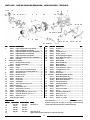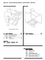
1
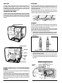
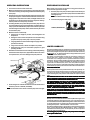
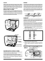
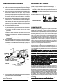
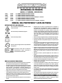
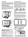
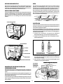
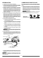
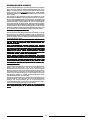
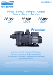
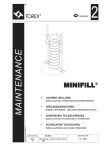
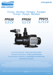
PRESSURE PUMP
FP25V
FP25VI
FP25H
FP25HE
FP25K
FP25Y
FP25YE
L1293Y
L1619Z
L1610Z
L1617Z
L1690Z
L1625Z
L1626Z
MODEL / UT NUMBER / DESCRIPTION:
2½-INCH PRESSURE PUMP, VANGUARD 13 ENGINE
2½-INCH PRESSURE PUMP, VANGUARD 13 ENGINE
2½-INCH PRESSURE PUMP, HONDA GX390 ENGINE
2½-INCH PRESSURE PUMP, HONDA GX390 ENGINE, ELECTRIC START
2½-INCH PRESSURE PUMP, KOHLER CS-12 ENGINE
2½-INCH PRESSURE PUMP, YANMAR DIESEL ENGINE
2½-INCH PRESSURE PUMP, YANMAR DIESEL ENGINE, ELECTRIC START
INSTRUCTIONS & PARTS LIST
SYMBOL DEFINITION
Do not pump flammable materials. Fire could occur.
Do not pump hazardous material.
Read your product literature before use.
Do not smoke or bring flame near gasoline.
Disconnect spark plug before performing
maintenance, adjustment, lubrication, and
storage.
SAFETY PRECAUTIONS
• This pump is designed for pumping clean water only. It should not be
used to pump sandy water or hazardous fluids.
• Before start-up, study all of the instructions in this manual. Be sure
you thoroughly understand how to operate the pump. Proper
preparation, operation and simple maintenance will improve operator
safety, pump performance and long unit life.
• Be sure that each person who operates the machine is properly
instructed as to its safe operation.
Part No. L00247 Rev. H 2010/06/01
• Always keep the machine and associated equipment clean, properly
serviced and maintained according to the instructions in this manual.
• Observe all safety regulations for the safe handling and storage of
fuel. Handle fuel in approved vented fuel cans. Do not store fuel
supplies in a garage, shed or other areas attached to living quarters.
Do not refill the fuel tank in an area attached to living quarters. Do not
refill the engine while it is running or hot. Carefully clean up any
spilled fuel before starting the engine.
• Do not smoke or bring flame near gasoline.
• Do not operate the pump at shut-off pressure for more than 2 minutes.
• Do not operate this pump if any safety equipment or guard has been
removed.
• Never operate the machine in any explosive atmosphere, near
combustible materials, or where there is not enough ventilation to
carry off the exhaust fumes. DO NOT operate pump indoors or in crawl
spaces.
• Always be sure the machine is on secure footing and cannot shift to
where it might injure someone. Remember that the suction hose on
the pump tends to pull the pump towards the liquid source during
pumping.
• Keep the immediate area free of bystanders.
• When pulling the starter, be sure that nothing is in a position to be hit
by the operator’s hand or arm, or the starting rope.
• Do not touch the hot cylinder and muffler area.
• Shut off the engine and disconnect the spark plug wire before working
on any part of the machine.
• Long or continuous exposure to high noise levels, such as the
operation of a gasoline engine, may cause permanent hearing
impairment or other possible effects. Hearing protection devices are
available from your dealer, or can be ordered through him.
• The discharge hose used with the FP25 must be able to withstand a
maximum pressure of 150 PSI (10.34 BAR).
• Use only genuine product manufacturer’s replacement parts. Failure
to do so may cause poor fit and possible injury.
• BEWARE OF USING THIS EQUIPMENT IN CONFINED SPACES.
Confined spaces, without sufficient fresh air ventilation, can contain
dangerous gases. Running gasoline engines in such environments
can lead to deadly explosions and/or asphyxiation.
THE FP25
STRAINER
The FP25 is ideal for handling clean water, free of solids and debris, and
for conditions where long hose runs are needed. Primarily used for
firefighting and emergencies, the FP25 can also be used for highperformance jetting, sprinkler systems, irrigation and water supply, and
for the washing and cleaning of equipment.
The strainer supplied with this pump is designed to fit a 4-inch hose. The
strainer orifices are sized to permit passage of solids that the unit is
designed to handle. Do not operate the pump without a strainer or use a
strainer with larger holes.
When the suction strainer is likely to clog with debris, tie it in a basket or
pail (A); prepare a bed of stones on which to rest the strainer (B); or tie the
strainer to a float so that it stays off the bottom (C).
UNCRATING THE PUMP
Look the unit over carefully for shipping damage. If you find any damage,
report it immediately to your dealer or the shipper. Read these instructions
and the engine instructions carefully until you are sure you can prepare
the engine and the pump properly for use, and can operate it safely and
correctly.
A
B
C
PRIMING
EXHAUST PRIMING HANDLE
The pump is self priming to lifts of 19 feet (5.8 m). The time required to
prime is greatly affected by the lift. For the shortest priming time, place
the pump as close to the water source as possible.
The pump depends upon water for internal lubrication; dry running will
quickly ruin the seal. If slow priming seems likely, fill the pump cavity with
water at the inlet nipple before starting the engine.
1. Start the engine, according to engine operating instructions supplied
with the pump. Set the engine speed control to full open position.
2. Place the priming valve on the pump inlet to the open position. (See
illustration.)
PRESSURE GAUGE
MUFFLER
PRIMING VALVE OPEN
PRIMING VALVE CLOSED
3. Grasp the handle and swing the cap against the opening very tightly
until the pump starts pumping.
4. When the pump begins pumping, release the handle allowing the cap
to swing clear of the muffler opening. Close the priming valve on the
pump inlet.
VENTURI
PRIMING
VALVE
PUMP
INLET
WARNING: Priming handle may be hot.
PUMP DRAIN PLUG
CLOSE TO
PRIME
DIESEL ENGINE AND 4-CYCLE ENGINE-DRIVEN
PUMPS
An engine manual for the specific engine is included. See Engine Manual
for fueling recommendations.
Diesel engines and 4-cycle engines have oil-filled crankcases which were
drained for shipment and must be refilled before operation of engine.
Read and follow all instructions in this Owner’s Manual and the Engine
Manual before performing any preparation, operation and maintenance
to the pump.
2
OPERATING INSTRUCTIONS
PREPARING FOR STORAGE
1. Use a strainer on the end of the suction line.
2. Make sure that all hose and pipe connections are air tight. An air leak
in the suction line may prevent priming and will reduce the lift capacity
of the pump.
3. Place the pump as close to the liquid to be pumped as possible. Keep
the pump and engine on a level foundation. When the suction hose is
hanging down a steep bank or into a hole, the weight of the hose and
the liquid in it can pull the pump into the liquid. To prevent “walking”
and the possible loss of the pump, tie it down.
4. In freezing weather, always drain the liquid from the pump after use
by removing the drain plug. In freezing weather, crank the engine very
slowly so you can feel whether the pump is free to run before you crank
to start the engine. If the pump is frozen, thaw it out slowly. Do not use
fire to thaw the pump.
5 Maximum volume is achieved by:
a. keeping lines as straight as possible, and avoiding kinks and
sharp bends.
b. making the vertical suction lift (distance from the water being
pumped to the pump suction port) as short as possible.
c. using large diameter suction and discharge lines (larger diameter
provides lower friction).
d. using as few connectors, elbows and adapters as possible.
e. maintaining the pump and associated equipment in good
operating condition.
6. If flexible hose must be laid across a roadway, protect it with planking.
Instantaneous shut-off pressures, applied when a vehicle runs across
an unprotected line, can cause damage to the pump and hose.
When product is to be stored or not used for a long period of time, the
pump should be prepared for storage:
1. Drain the pump. If the pump contains liquids which could dry out
and cake up, it is a good idea to pump a little clean water before
draining the pump.
NOTE: Flush with fresh water daily if pump is used in salt water.
2. Leave the drain plug out of the pump.
TO DRAIN, REMOVE PLUG
LIMITED WARRANTY
Riverside Pump Manufacturing Inc. warrants to the original retail purchaser that
this Riverside Pump Manufacturing Product is free from defects in material and
workmanship and agrees to repair or replace, at the discretion of Riverside Pump
Manufacturing, Inc., any defective Product free of charge within the time period
of Two Years from the date of purchase.
This warranty is not transferable and does not cover damage resulting from
defects other than in material or workmanship, or damage caused by
unreasonable use, including the failure to provide reasonable and necessary
maintenance. Also, the warranty obligations do not apply to conditions resulting
from misuse, alteration or accident. In addition, this warranty does not cover
replacement of non-defective parts (such as seals, wear plates and impellers)
that may wear and need to be replaced with reasonable use within the warranty
period or which may require replacement in connection with normal maintenance.
SAVE YOUR SALES SLIP
Proof of purchase in the form of your dated sales receipt, cash register slip, etc.
showing the serial number and the model of your Product will be required. You
must, at your own expense, arrange to deliver or ship the Product for warranty
repairs and arrange for pickup or return of the Product after repairs have been
made.
THIS WARRANTY DOES NOT APPLY TO ANY TRADE ACCESSORY OR ENGINE
WHICH IS SEPARATELY WARRANTED BY ANOTHER MANUFACTURER AND NOT
MANUFACTURED BY RIVERSIDE PUMP MANUFACTURING INC.
THIS LIMITED WARRANTY IS IN LIEU OF ALL OTHER EXPRESS WARRANTIES.
ANY IMPLIED WARRANTY OF FITNESS FOR A PARTICULAR PURPOSE,
MERCHANTABILITY OR OTHERWISE, APPLICABLE TO THIS PRODUCT, SHALL
BE LIMITED IN DURATION TO THE DURATION OF THIS LIMITED WARRANTY.
RIVERSIDE PUMP MANUFACTURING INC. SHA
LL NOT BE LIABLE FOR ANY
SHALL
SPECIAL, INCIDENTAL OR CONSEQUENTIAL DAMAGES.
SOME STATES DO NOT ALLOW LIMITATIONS ON HOW LONG AN IMPLIED
WARRANTY LASTS, SO THE ABOVE LIMITATION MAY NOT APPLY TO YOU. SOME
STATES DO NOT ALLOW THE EXCLUSION OR LIMITATION OF INCIDENTAL OR
CONSEQUENTIAL DAMAGES, SO THE ABOVE LIMITATION OR EXCLUSION MAY
NOT APPLY TO YOU.
PROTECT LINE
WITH TIMBERS
7. The discharge hose used with the FP25 must be able to withstand a
maximum pressure of 150 PSI (10.34 BAR).
NOTE: All connections on the suction side of the pump must be air tight.
HOW TO OBTAIN WARRANTY SERVICE
Warranty service can be obtained from a Riverside Pump Manufacturing Inc. dealer
or distributor authorized to make warranty repairs. If you need warranty service,
check first with the Riverside Pump Manufacturing dealer or distributor from whom
you purchased the Product, or call for the name and location of the nearest dealer
providing warranty service: 1-800-696-9005 or 1-843-537-5579.
Riverside Pump Manufacturing Inc. will not make any reimbursements for warranty
service, except to Riverside Pump Manufacturing Inc. dealers or distributors
authorized to make warranty repairs. You must present your sales receipt when
making any claim for warranty service.
This warranty gives you specific legal rights, and you may also have other rights
which vary from state to state.
3
POMPE REFOULANTE
FP25V
FP25VI
FP25H
FP25HE
FP25K
FP25Y
FP25YE
L1293Y
L1619Z
L1610Z
L1617Z
L1690Z
L1625Z
L1626Z
MODÈLE / UT NOMBRE / DESCRIPTION:
2½" POMPE HAUTE PRESSION, VANGUARD 13MOTEUR
2½" POMPE HAUTE PRESSION, VANGUARD 13MOTEUR
2½" POMPE HAUTE PRESSION, HONDA GX390 MOTEUR
2½" POMPE HAUTE PRESSION, HONDA GX390 MOTEUR, DÉMARRAGE - ÉLECTRIQUE
2½" POMPE HAUTE PRESSION, KOHLER CS-12 MOTEUR
2½" POMPE HAUTE PRESSION, YANMAR DIESEL MOTEUR
2½" POMPE HAUTE PRESSION, YANMAR DIESEL MOTEUR, DÉMARRAGE - ÉLECTRIQUE
INSTRUCTIONS ET LISTE DE PIECES DE RECHANGE
• Observer tous les règlements de sécurité s’appliquant à la
manipulation et à l’entreposage de carburant. Manipuler celui-ci
dans des récipients ventilés. Ne pas entreposer de carburant dans un
garage, un appentis ou tout autre emplacement jouxtant des
bâtiments d’habitation. Ne pas remettre de l’essence dans le réservoir
dans un tel emplacement. Ne pas refaire le plein du réservoir pendant
que le moteur tourne ou qu’il est encore chaud. Essuyer
soigneusement toute éclaboussure de carburant avant de faire
redémarrer le moteur.
• Ne pas fumer ni approcher de flamme près d’essence.
• Ne pas faire fonctionner la pompe à une pression d’arrêt pendant
plus de 2 minutes.
• Ne jamais utiliser cette machine si l’un des dispositifs de protection
n’est pas en place.
• Ne jamais faire fonctionner la machine dans une atmosphère propice
aux explosions, à proximité de matériaux combustibles ou dans un
endroit où la ventilation est insuffisante pour évacuer convenablement
les gaz d’échappement. NE PAS faire fonctionner la pompe à l’intérieur
ou dans le vide sanitaire sous la maison.
• Toujours s’assurer que la machine est stable et qu’elle ne peut pas se
déplacer jusqu’à un endroit où elle risque de blesser quelqu’un. Ne
pas oublier que le tuyau d’aspiration de la pompe tend à tirer celleci vers la source de liquide pendant le pompage.
• Éloigner toute personne non nécessaire au fonctionnement de la
pompe de sa proximité immédiate.
• Au moment du démarrage de la machine, s’assurer que rien ne fait
obstacle au déplacement de la main ou du bras de l’utilisateur, ni à
la course du cordon du démarreur.
• Ne pas toucher le cylindre ni la zone du silencieux d’échappement.
• Arrêter le moteur et débrancher le fil de la bougie avant de travailler
sur une pièce quelconque de la machine.
• L’exposition prolongée ou continue à des niveaux élevés de bruit, tels
ceux produits par un moteur à essence, risque de provoquer une
perte permanente d’acuité auditive ou d’avoir d’autres effets. Des
protecteurs individuels sont disponibles auprès de votre
concessionnaire ou peuvent être commandés par son intermédiaire.
• Le tuyau de vidange utilisé avec la FP25 doit pouvoir soutenir une
pression maximum de 150 PSI (10.34 BAR).
• Utiliser uniquement des pièces de rechange de la même marque.
D’autres pièces risquent de ne pas assurer un bon ajustement et
d’occasionner des blessures.
• ATTENTION SI VOUS UTILISEZ CET ÉQUIPEMENT DANS DES ESPACES
CONFINÉS. Les espaces confinés, sans ventilation d’air frais
suffisante, risquent de contenir des gaz dangereux. Faire fonctionner
un moteur à essence dans de tels cas peut provoquer une explosion
ou une asphyxie mortelle.
DÉFINITION DES SYMBOLES
Ne pas pomper de produits inflammables. Un incendie
risquerait de se produire.
Ne pas pomper de produits dangereux.
Lire les imprimés sur le produit.
Ne pas fumer ni approcher de flamme près d’essence.
Débrancher la bougie avant de procéder à
l’entretien, le réglage, la lubrification ou le
remisage de la pompe.
PRÉCAUTIONS DE SÉCURITÉ
• Cette pompe est conçue pour pomper de l’eau propre seulement.
Elle ne doit pas servir à pomper de l’eau sableuse ni des liquides
dangereux.
• Avant d’utiliser la pompe, étudier toutes les instructions données
dans ce manuel. S’assurer de bien en comprendre le fonctionnement.
Veiller à correctement la préparer, l’utiliser et en assurer l’entretien
de routine pour la sécurité de l’utilisateur, un rendement optimum et
une plus grande durabilité de la machine.
• S’assurer que chaque personne appelée à utiliser la machine a reçu
les instructions appropriées pour garantir un fonctionnement en
toute sécurité.
• Toujours faire en sorte que la machine et le matériel qui lui est
associé restent propres, convenablement révisés et entretenus,
conformément aux instructions données dans ce manuel.
4
LA FP25
CRÉPINE
La FP25 est idéale pour les endroits où l’eau est propre, sans solides et
débris, et lorsqu’il est nécessaire d’avoir un long tuyau. Bien qu’elle soit
essentiellement utilisée pour combattre les incendies et dans les cas
d’urgence, la FP25 peut également servir pour le fonçage au jet d’eau à
haute performance, les systèmes de gicleur, l’irrigation et l’alimentation
en eau, ainsi que pour laver ou nettoyer des machines.
La crépine fournie avec cette pompe est conçue pour d’adapter à un tuyau
de 2½ pouces (63.5 mm) de diamètre. Les orifices de la crépine sont
conçus pour laisser passer les solides d’une taille appropriée pour la
pompe. Ne pas faire fonctionner la pompe si la crépine n’est pas en place
ou si la pompe est munie d’une crépine avec des orifices de taille supérieure.
Lorsqu’il est probable que le filtre d’aspiration va être obturé par des
débris, accrochez-le dans un panier ou un sceau (A); préparez un lit de
pierres sur lequel vous poserez le filtre (B); ou bien fixez le filtre de façon
à ce qu’il ne repose pas sur le fond (C).
DÉBALLAGE DE LA POMPE
Vérifiez bien si la pompe n’a pas été endommagée pendant le transport.
S’il y a des dommages, signalez-le immédiatement au distributeur ou à
l’expéditeur. Lisez attentivement ces directives ainsi que celles
concernant le moteur, jusqu’à ce que vous soyez sûr de pouvoir préparer
le moteur et la pompe correctement pour l’emploi, et qu’elle peut être
mise en fonction correctement et en toute sécurité.
A
B
C
AMORÇAGE
POIGNÉE DE COMMANDE D’AMORÇAGE
La pompe s’amorce d’elle-même dans le cas d’une dénivellation allant
jusqu’à 5.8 m (19 pieds). Le temps d’amorçage dépend beaucoup de la
dénivellation. Pour le temps d’amorçage le plus court possible, placer la
pompe le plus près possible de la source d’eau.
La pompe a besoin d’eau pour sa lubrification interne. Un fonctionnement
à sec détruit rapidement le joint. S'il est probable que la pompe soit
lente pour devenir amorcée, avant de faire démarrer le moteur, remplir
l’intérieur de la pompe avec de l’eau à partir de l’orifice d’aspiration.
1. Faites démarrer le moteur. (Voir les directives de fonctionnement du
moteur fournies avec la pompe.) Réglez le contrôle du moteur en
position d’ouverture totale.
2. Placez la soupape d’amorçage de la canalisation d’arrivée de la
pompe en position ouverte. (Voir l’illustration.)
MANOMÈTRE
SILENCIEUX
OUVERTE
DIFFUSEUR
FERMÉE
PORT DE DÉCHARGE
3. Attrapez la poignée et faites pivoter le chapeau très près de l’ouverture
jusqu’à ce que la pompe commence à pomper.
4. Relâchez la poignée, ce qui éloignera le chapeau de l’ouverture du
silencieux. Fermez la soupape sur la canalisation d’arrivée de la
pompe.
BOUCHON DE VIDANGE
AVERTISSEMENT: La poignée de commande d’amorçage peut être chaude.
SOUPAPE
AMORÇAGE
FERMER POUR
AMORCER
POMPESÀ MOTEUR 4 TEMPS OU DIESEL
Un Manuel est fourni pour le moteur utilisé. Voir les recommandations
concernant le carburant dans le Manuel du moteur.
Le carter des moteurs diesel et 4-temps est vidé de son huile aux fins de
transport et doit être rempli avant de faire fonctionner le moteur.
Lire et suivre toutes les instructions de ce Manuel de l’utilisateur et du
Manuel du moteur avant de procéder à la préparation, l’utilisation et
l’entretien de cette pompe.
5
DIRECTIVES DE FONCTIONNEMENT
ENTREPOSAGE DE L’APPAREIL
1. Il est préférable de mettre un filtre à la fin de la tuyauterie d’aspiration.
2. Veillez à ce que tous les raccords de boyaux et de tuyaux soient bien
étanches. S’il y a une fuite dans la tuyauterie d’aspiration, l’amorçage
risque de ne pas se faire et la capacité d’aspiration de la pompe sera
réduite.
3. Placez la pompe aussi près du liquide à pomper que possible. Posez
la pompe et le moteur sur une base plane. Lorsque le boyau
d’aspiration descend le long d’une pente abrupte, ou dans un trou, le
poids du tuyau et le liquide qu’il contient peuvent entraîner la pompe
dans le liquide. Pour éviter que la pompe « avance », et peut-être
même qu’elle soit perdue, attachez-la.
4. En période de gel, il faut toujours purger la pompe du liquide après
utilisation. Pour cela, il suffit d’enlever le bouchon de vidange. Par
temps de gel, vous devez aussi faire tourner le moteur très lentement
avant de le lancer, pour vérifier si la pompe n’est pas bloquée. Si le
moteur est gelé, faites-le dégeler lentement (n’utilisez pas de feu
pour dégeler la pompe).
5. Pour pomper un maximum de volume :
a. Les tuyaux doivent être aussi droits que possible, en évitant les
pliures et les coudes aigus.
b. La distance d’aspiration verticale doit être aussi courte
quepossible.
c. Utilisez des tuyaux d’aspiration et de vidange ayant un grand
diamètre (plus le diamètre est large, moins il y a de friction).
d. Utilisez aussi peu de raccords, de coudes et d’adaptateurs que
possible.
e. Maintenez la pompe et tout équipement connexe en bon état de
fonctionnement.
6. Si une conduite flexible doit traverser une voie d’accès, protéger la
conduite à l’aide de planches. Les surpressions instantanées résultant
du passage d’un véhicule sur une conduite non protégée causent un
effet de bélier. L’effet de bélier peut fendre le corps de pompe ou
endommager la conduite.
Lorsqu’il est prévu de ne pas utiliser l’appareil pendant de longues
périodes, la pompe doivent être préparés en vue de stockage :
1. Vidanger la pompe; Si la pompe contient des liquides pouvant sécher
et former des dépôts solides, il est recommandé de pomper un peu
d’eau propre avant de vidanger la pompe.
REMARQUE: Rincer à l’eau fraîche chaque jour si la pompe aspire de
l’eau salée.
2. Enlever les bouchons de vidange de la pompe.
POUR VIDANGER,
ENLEVEZ LE BOUCHON
GARANTIE LIMITÉE
Riverside Pump Manufacturing Inc. garantit à l’acquéreur original (vente au
détail) que ce produit Riverside Pump Manufacturing ne présente pas de défauts
de matière ou de main d’oeuvre, et s’engage à réparer ou à remplacer (à la
discrétion de Riverside Pump Manufacturing's) n’importe quel produit défectueux
gratuitement au cours de la période de temps Deux Ans de la date de l’achat.
La présente garantie n’est pas cessible ; elle ne couvre pas les dommages ne
découlant pas de défauts de matière ou de main d’oeuvre, ni les dommages
causés par une utilisation non raisonnable, en particulier tout manquement à
assurer l’entretien raisonnable et nécessaire. De plus, la garantie ne s'étend
pas aux conditions découlant d'un mauvais usage, d'une modification ou d'un
accident. De plus, la présente garantie ne couvre pas les vérifications ou le
remplacement de pièces non-défectueuses (sello, placa de desgaste, impulsor)
sujettes à l’usure et nécessitant unremplacementdans le cas d’une utilisation
raisonnable pendant la période couverte par la garantie, ou susceptibles d’être
remplacées à l’occasion d’opérations d’entretien normales.
CONSERVEZ VOTRE REÇU
Une preuve d’achat, sous forme de reçu de vente daté, ticket de caisse, etc.
indiquant le numéro de série et le modèle de votre Produit sera exigée avant
toute intervention de nos concessionnaires sur le Produit sous garantie. Vous
devrez obligatoirement assurer à vos frais la livraison ou l’expédition du produit
en cas de réparations sous garantie, ainsi que la reprise ou le retour du Produit
après réparation.
LA PRÉSENTE GARANTIE NE S’APPLIQUE PAS AUX ACCESSOIRES
PROFESSIONNELS, MOTEURS COUVERTS PAR LA GARANTIE D’UN AUTRE
FABRICANT ET NON FABRIQUÉS PAR RIVERSIDE PUMP MANUFACTURING INC.
LA PRÉSENTE GARANTIE LIMITÉE TIENT LIEU DE TOUTE AUTRE GARANTIE
EXPLICITE. LA DURÉE DE TOUTE GARANTIE IMPLICITE D’APTITUDE À UNE FIN
QUELCONQUE, DE QUALITÉ MARCHANDE OU AUTRE, APPLICABLE À CE
PRODUIT, SERA LIMITÉE À LA DURÉE DE LA PRÉSENTE GARANTIE LIMITÉE.
RIVERSIDE PUMP MANUFACTURING INC. NE SERA RESPONSABLE D’AUCUNS
DOMMAGES SPÉCIAUX, ACCESSOIRES OU INDIRECTS.
CERTAINS ÉTATS INTERDISENT DE LIMITER LA DURÉE D’UNE GARANTIE
IMPLICITE ; DE CE FAIT, LA LIMITE CI-DESSUS PEUT NE PAS S’APPLIQUER À
VOUS. CERTAINS ÉTATS INTERDISENT L’EXCLUSION OU LA LIMITE DES
DOMMAGES ACCESSOIRES OU INDIRECTS ; DE CE FAIT, LA LIMITE OU
L’EXCLUSION CI-DESSUS PEUT NE PAS S’APPLIQUER À VOUS.
COMMENT OBTENIR UNE RÉPARATION SOUS GARANTIE
Une réparation sous garantie peut être obtenue auprès d’un concessionnaire
Riverside Pump Manufacturing Inc. agréé pour effectuer des réparations sous
garantie. Si vous avez besoin d’une réparation sous garantie, commencez par
prendre contact avec le concessionnaire ou le distributeur Riverside Pump
Manufacturing chez qui vous avez acheté le produit, ou téléphonez au numéro
ci-dessous pour obtenir le nom et l’adresse du concessionnaire le plus proche
assurant les réparations sous garantie : 888-696-9005 ou 843-537-5589.
Riverside Pump Manufacturing ne rembourse aucune réparations effectuées
sous garantie, sauf aux concessionnaires ou distributeurs Riverside Pump
Manufacturing agréés pour effectuer les réparations sous garantie. Vous devrez
obligatoirement présenter votre reçu de vente lors d’une demande de réparation
sous garantie.
La présente garantie vous donne des droits légaux spécifiques, et vous pouvez
également bénéficier d’autres droits variant d’un état à un autre.
PROTÉGER LES CONDUITES
FLEXIBLES TRAVERSANT LES
VOIES D’ACCÈS À L’AIDE DE
PLANCHES.
7. Le boyau de vidange utilisé avec la FP25 doit pouvoir supporter une
pression maximum de 150 PSI (10.34 BAR).
REMARQUE : Tous les raccords du côté de l'aspiration de la pompe
doivent etre entanches.
6
MOTOBOMBA DE PRESIÓN
FP25V
FP25VI
FP25H
FP25HE
FP25K
FP25Y
FP25YE
L1293Y
L1619Z
L1610Z
L1617Z
L1690Z
L1625Z
L1626Z
MODELO / UT NÚMERO / DESCRIPCIÓN:
2½" BOMBA DE PRESIÓN, VANGUARD 13 MOTOR
2½" BOMBA DE PRESIÓN, VANGUARD 13 MOTOR
2½" BOMBA DE PRESIÓN, HONDA GX390 MOTOR
2½" BOMBA DE PRESIÓN, HONDA GX390 MOTOR, ARRANQUE - ELÉCTRICO
2½" BOMBA DE PRESIÓN, KOHLER CS-12 MOTOR
2½" BOMBA DE PRESIÓN, YANMAR DIESEL MOTOR
2½" BOMBA DE PRESIÓN, YANMAR DIESEL MOTOR, ARRANQUE - ELÉCTRICO
MANUAL DEL PROPIETARIO Y LISTA DE PIEZAS
DEFINICIONES DE LOS SIMBOLOS
No use la bomba para materiales inflamables. Podría
ocurrir un incendio.
• Respete todas las reglas de seguridad para el manipuleo y
almacenamiento del combustible. Coloque el combustible en
recipientes para combustibles con orificios de ventilación. No
almacene el combustible en un garaje, cobertizo u otros sitios
contiguos a áreas habitadas. No llene el tanque del combustible en
una zona contigua a áreas habitadas. No llene el tanque mientras el
motor esté caliente o en funcionamiento. Antes de encender el
motor, limpie con cuidado el combustible que pudiera haberse
derramado.
• No fume ni acerque ninguna llama a las proximidades de la gasolina.
• No opere la bomba a presión de cierre durante más de 2 minutos.
• No utilice esta bomba, si han quitado el equipo o a los protectores de
seguridad.
• Nunca se debe operar la máquina en una atmósfera explosiva, cerca
de materiales combustibles o en lugares en los cuales no haya
suficiente ventilación para dejar salir los gases de escape. NO opere
la bomba dentro de una habitación o en espacios muy pequeños.
• Asegúrese siempre de que la máquina esté apoyada sobre una base
segura y no pueda deslizarse y causar daño a persona alguna.
Recuerde que la manguera de succión de la bomba tiende a tirar la
bomba hacia el lugar donde se encuentra el líquido durante el
bombeo.
• Mantenga a todas las personas alejadas del área cercana a la
bomba.
• Cuando proceda a poner en marcha la máquina, asegúrese de que no
haya ningún objeto alrededor que pueda ser golpeado por la mano o
el brazo del operario o la cuerda para poner en marcha la unidad.
• No toque el área del amortiguador ni el cilindro caliente.
• Apague el motor y desconecte el cable de la bujía antes de reparar
cualquier parte de la máquina.
• La exposición prolongada o continua a altos niveles de ruido, tal
como aquél producido por la operación de un motor a gasolina,
puede causar una deficiencia auditiva permanente u otros efectos
posibles. Su vendedor puede proveerle o encargarle protectores
para los oídos.
• La manguera de descarga de la bomba FP25 debe tener capacidad
para soportar una presión máxima de 150 libras (10.34 BAR) por
pulgada cuadrada.
• Use solamente repuestos genuinos del fabricante. El no hacer esto
podría causar un ajuste incorrecto y ocasionar lesiones posibles.
• EVITE EL USO DE ESTE EQUIPO EN ESPACIOS CERRADOS
CERRADOS. Los
espacios cerrados con ventilación insuficiente pueden albergar gases
peligrosos. El funcionamiento de motores a gasolina en dichos
espacios implica riesgo de explosión y/o asfixia.
No use la bomba para materiales peligrosos.
Lea el manual del producto.
No fume ni acerque ninguna llama a las proximidades
de la gasolina.
Desconecte la bujía antes de efectuar el
mantenimiento, ajuste, lubricación y
almacenamiento de la bomba.
PRECAUCIONES DE SEGURIDAD
• Esta bomba está diseñada para bombear agua limpia únicamente.
No usarla para bombear agua arenosa ni fluidos peligrosos.
• Lea todas las instrucciones de este manual antes de poner en marcha
la bomba. Asegúrese de comprender completamente el modo de
operar la bomba. Una preparación y operación adecuadas y un
mantenimiento sencillo producirán un funcionamiento óptimo y
seguro para el operador y una larga vida útil de la unidad.
• Asegúrese de que todas las personas que operen la máquina hayan
sido debidamente instruidas sobre la forma segura de su uso.
• Asegúrese siempre de que la máquina y todo el equipo asociado
estén limpios y reciban el mantenimiento adecuado, de acuerdo con
las instrucciones de este manual.
• No opere nunca la unidad cuando la protección no se encuentre en
su sitio.
7
LA UNIDAD FP25
ALCACHOFA DE ASPIRACION
La unidad FP25 es ideal para el bombeo de agua limpia, sin sólidos ni
residuos en suspensión, y para bombeo con tramos largos de manguera.
La unidad FP25 se usa principalmente para combatir incendios y en
situaciones de emergencia, pero también se puede utilizar para chorros
a alta presión, sistemas de riego, suministro de agua potable y para
lavado y limpieza de equipos y maquinarias.
La alcachofa de aspiración que se suministra con esta bomba ha sido
diseñada para adaptarse a una manguera de 2½ pulgadas (63.5 mm).
El tamaño de los orificios de la alcachofa de aspiración permite el paso
de los elementos sólidos que pueden ser aceptados por la unidad de
conformidad con las especificaciones de su diseño. No opere la bomba
sin una alcachofa de aspiración ni utilice una alcachofa de aspiración
que tenga unos orificios más grandes.
Cuando haya posibilidad de que la malla filtrante de aspiración se tape
con material extraño: colocar el filtro en un cesto o balde (A); construir un
lecho de piedras para la malla de filtro(B); o atar la línea de aspiración
para que se mantenga alejado del fondo (C).
DESEMBALAJE DE LA BOMBA
Inspeccionar la unidad minuciosamente para detectar si se produjeron
daños durante el transporte. En caso afirmativo, informar sobre los
daños encontrados inmediatamente al comercio vendedor o a la
compañía de transporte. Leer atentamente estas instrucciones y las
instrucciones correspondientes al motor, hasta estar seguro de que
puede preparar el motor y la bomba para la puesta en servicio, y usarlos
correctamente y con seguridad.
A
MANIJA DEL OSCURECIMIENTO DE LA BOMBA
B
C
CEBADO
La bomba es autocebante a unas alturas de impulsión de hasta 19 pies
(5.8 m). El tiempo necesario para el cebado depende en gran medida de
la altura de impulsión. Con el fin de que el tiempo de cebado sea lo más
reducido posible, coloque la bomba lo más cerca que pueda de la fuente
de agua.
La bomba depende del agua para su lubricación interna; el
funcionamiento en seco destruirá rápidamente el anillo obturador. Si se
parece el cebado lento probablemente, llene la cavidad de la bomba de
agua en la entre rosca de la entrada antes de encender el motor.
1. Arrancar el motor (consultar las instrucciones de uso suministradas
con el motor). Colocar la válvula reguladora del motor en posición
totalmente abierta.
2. Al igual que la válvula de cebado ubicada en el lado de admisión de
la bomba (véase la ilustración).
MANOMETRO
SILENCIADOR
DIFUSOR DE
ESCAPE
VALVULA
LA VÁLVULA ESTÁ ABIERTA
LA VÁLVULA ES CERRADA
3. Empujar la palanca de cebado hacia la abertura del escape y
sostenerla firmemente en esa posición hasta que se inicie el bombeo.
4. Soltar la palanca y verificar que quede alejada de la salida del
silenciador de escape. Cerrar la válvula de cebado del lado de
aspiración.
ADVERTENCIA: La palanca de cebado puede estar caliente.
ADMISION DE
BOMBA
TAPON DE DRENAJE DE BOMBA
CERRAR
PARA
CEBAR
BOMBAS CONDUCIDAS POR MOTORES DIESEL
Y POR MOTORES DE 4 CICLOS
Se incluye un Manual del Motor para el motor específico. Consulte el
Manual del Motor para las recomendaciones de llenado con combustible.
Las cajas del cigueñal de los motores diesel y los motores de 4 ciclos se
llenan con aceite y fueron drenadas para su envío; deben volver a llenarse
antes de operar el motor.
Lea y siga todas las instrucciones que aparecen en este Manual del
Propietario y en el Manual del Motor antes de preparar, operar o realizar
el mantenimiento de la bomba.
8
INSTRUCCIONES DE USO
ALMACENAMIENTO DE LA UNIDAD
1. Es conveniente usar una malla de filtro en el extremo de la línea de
aspiración.
2. Verificar la hermeticidad de todas las conexiones de mangueras y
tuberías. Una entrada de aire en la línea de aspiración puede dificultar
e incluso impedir el cebado, reduciendo consecuentemente la presión
de bombeo.
3. Instalar la bomba tan cerca como sea posible del líquido a bombear,
y montar la unidad motor-bomba sobre una superficie nivelada.
Cuando la magullar de aspiración quede colgando hacia abajo en
una pendiente o un pozo, el peso de la misma y del líquido en ella
contenida pueden arrastrar la bomba. Para evitar esto, es conveniente
en estos casos fijar la bomba a la superficie de apoyo.
4. En climas gélidos, drenar siempre el líquido de la bomba después de
usarla. Para ello, simplemente abrir el tapón de drenaje. En climas
gélidos, dar primero «toques» cortos de arranque para verificar que
la bomba gire libremente, y después arrancar normalmente el motor.
Si la bomba estuviera congelada, descongelarla lentamente (no usar
fuego para descongelar la bomba).
5. Para obtener el caudal máximo de bombeo:
a) Mantener la línea tan recta como se posible, evitando
estrangulamientos y curvas cerradas.
b) Acortar al mínimo los tramos ascendentes de bombeo.
c) Usar líneas de aspiración y descarga del mayor diámetro posible
(a mayor diámetro, menor fricción).
d) Usar la mínima cantidad posible de conectores, codos y
adaptadores.
e) Mantener la bomba y equipos a ella conectados, en óptimas
condiciones de uso.
6. En caso de que se deba utilizar una manguera flexible que atraviese
una carretera, se deberá proteger con tablones de madera. Las
presiones de cierre instantáneo, aplicadas cuando un vehículo pasa
por encima de una manguera que no se encuentra protegida, provocan
la afluencia súbita de agua. Esta afluencia súbita de agua puede
separar el cuerpo de la bomba o dañar la manguera.
Cuando el bomba vaya a estar parado durante un período de tiempo
largo, debe ser preparado para el almacenaje:
1. Vacíe la bomba. Si la bomba contiene líquidos que pueden secarse
y solidificarse, se recomienda bombear un poco de agua limpia
antes de vaciar la bomba.
NOTA: Lavar con agua dulce todos los dias en caso de que la bomba
haya sido utilizada con agua salada.
2. Deje los tapones de vaciado fuera de la bomba.
SACAR EL TAPON
PARA DRENAR
GARANTIA LIMITADA
La Riverside Pump Manufacturing Inc. le garantiza al comprador original al por
menor que este producto Riverside Pump Manufacturing Inc. se encuentra libre
de defectos de material y mano de obra, y acepta reparar o reemplazar, a
discreción de Riverside Pump Manufacturing Inc. cualquier producto defectuoso
gratuitamente dentro del período de Dos Años a partir de la fecha de la compra.
La presente garantía no es transferible y no cubre los daños derivados de
defectos que no sean de material o mano de obra, o daños causados por
utilización no razonable, incluido el hecho de que no se haya proporcionado el
mantenimiento razonable y necesario. Las obligaciones de la garantía no se
aplican a las condiciones que resulten del mal uso o modificación, o accidente.
Además, la presente garantía no cubre o reemplazo de piezas no defectuosas
(tales como bague d'etancheite, enlever, roue) que se puedan desgastar y que
necesiten ser reemplazadas debido al uso razonable dentro del período de
garantía, o que pueda ser necesario reemplazar en conexión con las operaciones
normales de mantenimiento.
GUARDE SU COMPROBANTE DE VENTA
Se requerirá el comprobante de compra en la forma de recibo de venta con la
fecha, comprobante de la caja registradora, etc. en el que se indique el número
de serie y el modelo de su Producto. Para que se efectúen las reparaciones
relacionadas con la garantías, usted habrá de encargarse de la entrega o del
envío del Producto, debiendo hacer frente a los gastos que se deriven de ello.
Usted habrá de encargarse igualmente de recoger o devolver el Producto una vez
que se hayan efectuado las reparaciones.
ESTA GARANTÍA NO SE APLICA A NINGÚN ACCESORIO, MOTOR QUE SE
ENCUENTRE GARANTIZADO DE FORMA INDEPENDIENTE POR OTRO
FABRICANTE O QUE NO ESTÉ FABRICADO POR RIVERSIDE PUMP
MANUFACTURING INC.
ESTA GARANTIA LIMITADA SUSTITUYE A CUALESQUIERA OTRAS GARANTIAS
EXPRESAS. CUALQUIER GARANTIA IMPLICITA SOBRE LA IDONEIDAD DEL
PRODUCTO PARA FINES PARTICULARES, MERCANTILES O DE OTRO TIPO,
APLICABLE A ESTE PRODUCTO, TENDRA UNA DURACION LIMITADA A LA
DURACION DE LA GARANTIA LI
MITADA. RIVERSIDE PUMP MANUFACTURING
LIMITADA.
INC. NO SERA RESPONSABLE DE NINGUN TIPO DE DAÑOS ESPECIALES,
INCIDENTALES O CONSECUENCIALES.
ALGUNOS ESTADOS NO PERMITEN LIMITACIONES EN CUANTO A LA DURACION
DE LA GARANTIA IMPLICITA, DE MANERA QUE ES POSIBLE QUE A USTED NO
SE LE APLIQUE LA LIMITACION INDICADA MAS ARRIBA. ALGUNOS ESTADOS
NO PERMITEN LA EXCLUSION O LIMITACION DE DAÑOS INCIDENTALES O
CONSECUENCIALES, DE MANERA QUE POSIBLEMENTE A USTED NO SE LE
APLIQUE LA LIMITACION INDICADA MAS ARRIBA.
COMO OBTENER EL SERVICIO DERIVADO DE LA GARANTIA
El servicio derivado de la garantía puede ser obtenido en cualquier distribuidor
Riverside Pump Manufacturing Inc. autorizado para efectuar las reparaciones que
resulten necesarias. En caso de que usted necesite alguna operación de servicio
derivada de la garantía, verifique primero cuál es el distribuidor de Riverside Pump
Manufacturing Inc. al que le compró el Producto, o llame al siguiente número de
teléfono donde se le indicará cuál es el distribuidor más próximo a usted que
presta servicio de garantía: 888-696-9005 o 843-537-5589.
Riverside Pump Manufacturing Inc. no efectuará reembolsos por las operaciones
de servicio derivadas de la garantía, excepto cuando sean efectuadas por
distribuidores Riverside Pump Manufacturing que estén autorizados para llevar
a cabo las reparaciones relacionadas con la mencionada garantía. Usted
deberá presentar el justificante de venta cuando efectúe una reclamación
relacionada con las operaciones de servicio derivadas de la garantía.
Esta garantía le proporciona derechos legales específicos; además, usted
puede tener otros derechos que varían en función de los diferentes estados.
PROTEJA LA MANGUERA FLEXIBLE
CON TABLONES DE MADERA QUE
ATRAVIESEN LA CARRETERA
7. La manguera de descarga de la bomba FP25 debe tener capacidad
para soportar una presión máxima de 150 libras (10.34 BAR) por
pulgada cuadrada.
NOTA
NOTA: Todas las conexiones en la linea de aspiracion deben ser
hermeticas.
9
DRUCKPUMPE
FP25V
FP25VI
FP25H
FP25HE
FP25K
FP25Y
FP25YE
L1293Y
L1619Z
L1610Z
L1617Z
L1690Z
L1625Z
L1626Z
MODELL / UT NUMMER / BESCHREIBUNG:
2½" DRUCKPUMPE, VANGUARD 13 MOTOR
2½" DRUCKPUMPE, VANGUARD 13 MOTOR
2½" DRUCKPUMPE, HONDA GX390 MOTOR
2½" DRUCKPUMPE, HONDA GX390 MOTOR, STARTSYSTEM - ELEKTRISCH
2½" DRUCKPUMPE, KOHLER CS-12 MOTOR
2½" DRUCKPUMPE, YANMAR DIESEL MOTOR
2½" DRUCKPUMPE, YANMAR DIESEL MOTOR, STARTSYSTEM - ELEKTRISCH
ANLEITUNG UND TEILELISTE
ERKLÄRUNG DER SYMBOLE
Keine brennbaren Materialien pumpen. Es kann zu
Bränden kommen.
• Befolgen Sie alle Sicherheitsvorschriften für den sicheren Transport
und die sichere Aufbewahrung von Kraftstoffen. Transportieren Sie
Kraftstoff in zugelassenen belüfteten Kraftstoffkanistern. Lagern Sie
Kraftstoffvorräte nicht in Garagen, Schuppen oder anderen Bereichen,
die an Wohnräume angrenzen. Füllen Sie den Kraftstofftank nicht in
einem Bereich, der an Wohnräume angrenzt. Füllen Sie den Motor
nicht, während er läuft oder heiß ist. Beseitigen Sie verschütteten
Kraftstoff sorgfältig, bevor Sie den Motor starten.
• Rauchen Sie nicht und bringen Sie keine Flammen in die Nähe von
Benzin.
• Betreiben Sie die Pumpe nicht länger als 2 Minuten bei Abschaltdruck.
• Lassen Sie nicht diese Maschine laufen, wenn irgendeine Sicherheit
Ausrüstung fehlt.
• Betreiben Sie die Maschine nicht in einer explosionsgefährdeten
Atmosphäre, in der Nähe von brennbaren Materialien oder an Orten,
die nicht ausreichend belüftet sind, um die Abgase abzuleiten.
Betreiben Sie die Pumpe NICHT in Innenräumen oder in Kriechräumen.
• Achten Sie immer darauf, dass die Maschine sicher steht und nicht
kippen und jemanden verletzen kann. Denken Sie daran, dass der
Saugschlauch der Pumpe während des Pumpens dazu neigt, die
Pumpe in Richtung Flüssigkeit zu ziehen.
• Halten Sie den unmittelbaren Bereich frei von Zuschauern.
• Achten Sie beim Ziehen des Anlassers darauf, dass nichts im Weg
steht, das von der Hand oder dem Arm des Bedieners oder durch das
Starterseil getroffen werden könnte.
• Berühren Sie den heißen Zylinder und den Schalldämpferbereich
nicht.
• Schalten Sie den Motor aus und trennen Sie das Zündkerzenkabel,
bevor Sie an einem Teil der Maschine arbeiten.
• Lange oder ständige Bloßstellung eines hohen Geräuschpegels,
beispielsweise beim Betrieb eines Motors, kann zu ständiger
Hörbehinderung oder anderen möglichen Folgen führen. Einen
Gehörschutz erhalten Sie bei Ihrem Händler oder können Sie über ihn
bestellen.
• Der Entladung Schlauch, der mit dem FP25 benutzt wird, muß der
Lagesein, einem maximalen Druck von 150 psi (10.34 bar) zu
widerstehen.
• Verwenden Sie nur Originalersatzteile des Produktherstellers.
Nichtbefolgen kann schlechten Sitz und mögliche Verletzungen
verursachen.
• PASSEN SIE AUF BEI VERWENDUNG DIESER GERÄTE IN ENGE
RAUMEN. Enge Räume ohne ausreichende Frischluftversorgung
können gefährliche Gase enthalten. Das Betreiben von Motoren in
solchen Umgebungen kann zu tödlichen Explosionen und/oder
Erstickung führen.
Keine gefährlichen Materialien pumpen.
Vor Gebrauch Produktliteratur durchlesen.
Nicht rauchen oder Flammen in die Nähe von Benzin
bringen.
Zündkerze vor der Wartung, Einstellung,
Schmierung und Lagerung trennen.
SICHERHEITSMASSNAHMEN
• Diese Pumpe ist nur für das pumpen von sauberen Wasser gedacht.
Sie sollte unter keinen Umständen für das pumpen gefährlicher
Materialien verwendet werden, beispielsweise brennbarer
Materialien wie Benzin.
• Lesen Sie alle Anleitungen in diesem Handbuch vor der
Inbetriebnahme durch. Stellen Sie sicher, dass Sie vollkommen
verstanden haben, wie die Pumpe funktioniert. Ordnungsgemäße
Vorbereitung, Betrieb und einfache Wartung verbessern die Sicherheit
des Bedieners, die Pumpenleistung und die lange Lebensdauer des
Geräts.
• Stellen Sie sicher, dass jede Person, die die Maschine bedient,
ordnungsgemäß in Bezug auf den sicheren Betrieb ausgebildet wurde.
• Sorgen Sie dafür, dass die Maschine und die damit verbundenen
Geräte gemäß der Anleitung in diesem Handbuch sauber,
ordnungsgemäß repariert und gewartet sind.
10
DIE DRUCKPUMPE FP25
SIEB
Die Druckpumpen FP25 werden auf unterschiedliche Weise genutzt, zum
Beispiel bei der Brandbekämpfung, der Reinigung von Frachtschiffen
und Anlagen oder der Beregnung von Nutzpflanzen. Sie zeichnen sich aus
durch eine hohe Förderleistung und einen hohen Druck.
Das mit dieser Pumpe mitgelieferte Sieb ist für einen 2.5-Zoll-Schlauch
gedacht. Die Sieböffnungen sind so groß, dass sie Feststoffe
hindurchlassen, für die das Gerät ausgelegt ist. Betreiben Sie die Pumpe
nicht ohne Sieb und verwenden Sie kein Sieb mit größeren Löchern.
Wenn das Saug sieb wegen Fremdkörpern verstopft, verbinden Sie es mit
einem Korb oder Eimer (A), bereiten Sie ein Steinbett vor, auf das Sie das
Sieb stellen (B), oder verbinden Sie das Sieb mit einem Schwimmer, so
dass es vom Boden entfernt bleibt (C).
AUSPACKEN DER PUMPE
Achten Sie sorgfältig auf Versandschäden. Wenn Sie irgendeinen Schaden
bemerken, benachrichtigen Sie Ihren Händler oder den Spediteur.
Entfernen Sie alle Versandblöcke und Klammern. Wenn das Gerät einen
Motorantrieb hat, ist es sehr wichtig, dass dieser frei auf den Federn
schwebt.
A
B
C
AUSPUFFANSAUGGRIFF
VORFÜLLEN
Die für das Vorfüllen erforderliche Zeit wird durch die Förderhöhe erheblich
beeinflusst. Stellen Sie für eine möglichst kurze Vorfüllzeit die Pumpe so
nahe zur Wasserquelle wie möglich.
Die Pumpe benötigt Wasser für die interne Schmierung; Trockenlaufen
zerstört in Kürze die Dichtung. Wenn langsamer Ansaugen wahrscheinlich
scheint, füllen Sie den Pumpenhohlraum mit Wasser am Eingang Nippel,
bevor Sie den Motor starten.
1. Schalten Sie die Maschine, entsprechend der Maschine
Bedienungsanleitung ein, die mit der Pumpe geliefert wurden.
2. Drehen Sie das Schieß-Zündsatz Ventil zur geöffneten Position.
(Sehen Sie Abbildung.)
DRUCKANZEIGER
AUSPUFF
VENTURI
VENTIL GEÖFFNET FÜR
AUSPUFFANSAUGHILFE
ANSAUGVENTIL
VENTIL SCHLOSS FÜR DAS
FUNKTIONIEREN
3. Verschieben Sie den Handgriff, damit der Maschine Absaugventilator
durch das Venturi verwiesen wird. Halten Sie ihn fest, bis die Pumpe
zum Pumpwasser anfängt.
4. Wenn die Pumpe vorbereitet wird, geben Sie den Handgriff frei und
schließen Sie das Auspuffansaugventil.
PUMPEINGANG
ENTWASSERUNGSCHRAUBE
SCHLIESSEN
SIE FÜR DAS
VORBEREITEN
DER PUMPE
PUMPEN MIT DIESELMOTOREN UND
VIERTAKTMOTOREN
Eine Betriebsanleitung für den jeweiligen Motor liegt bei. Empfehlungen
bezüglich des Kraftstoffs sind in der Betriebsanleitung für den Motor zu
finden.
Dieselmotoren und Viertaktmotoren haben gefüllte Kurbelgehäuse, die
für den Versand entleert wurden und vor der Inbetriebnahme des Motors
wieder gefüllt werden müssen.
Vor der Vorbereitung, dem Betrieb und der Wartung der Pumpe sind alle
Anweisungen dieser Betriebsanleitung und der des Motors durchzulesen
und zu befolgen.
11
GEFAHR: Handgriff kann heiß sein!
BETRIEBSANLEITUNG
VORBEREITEN DER PUMPE FÜR ABLAGE
1. Verwenden Sie ein Sieb am Ende der Saugleitung.
2. Stellen Sie sicher, dass alle Schlauch- und Rohranschlüsse luftdicht
sind. Eine Luftdurchlässigkeit in der Saugleitung kann das Vorfüllen
verhindern und verringert die Hubleistung der Pumpe.
3. Stellen Sie die Pumpe so nah wie möglich zur zu pumpenden
Flüssigkeit. Stellen Sie die Pumpe und den Motor auf eine ebene
Grundlage. Wenn der Saugschlauch eine steile Böschung oder ein
Loch hinunter hängt, kann das Gewicht des Schlauchs und der darin
befindlichen Flüssigkeit die Pumpe in die Flüssigkeit ziehen. Um ein
“Wandern” und den möglichen Verlust der Pumpe zu verhindern,
sollten Sie sie befestigen.
4. Entleeren Sie bei Temperaturen unter dem Gefrierpunkt nach
Gebrauch immer die Flüssigkeit aus der Pumpe, indem Sie die
Ablassschraube entfernen. Lassen Sie bei Temperaturen unter dem
Gefrierpunkt den Motor langsam an, so dass Sie merken, ob die
Pumpe frei laufen kann, bevor Sie den Motor starten. Wenn die
Pumpe eingefroren ist, lassen Sie sie langsam aufwärmen. Verwenden
Sie zum Aufwärmen der Pumpe kein Feuer.
5. Sie erreichen das maximale Volumen, indem Sie:
a. die Schläuche so gerade wie möglich verlegen und ein Abknicken
und scharfe Biegungen vermeiden.
b. der vertikalen Saugförderhöhe (Abstand vom zu pumpenden
Wasser zum Sauganschluss der Pumpe) so kurz wie möglich
machen.
c. Saug- und Druckleitungen mit dem richtigen Durchmesser
verwenden (größere Durchmesser sorgen für weniger Reibung).
d. so wenige Anschlüsse, Bögen und Adapter wie möglich
verwenden.
e. die Pumpe und die damit verbundenen Geräte in gutem
Betriebszustand halten.
ANMERKUNG
ANMERKUNG: Alle Anschlüsse am Ansaugenden der Pumpe müssen
luftdicht sein. Der Saugschlauch oder das Saugrohr dürfen nicht
zusammenfaltbar sein.
6. Wenn der flexible Schlauch über eine Straße verlegt werden muss,
schützen Sie ihn durch Planken. Plötzlicher Abschaltdruck, wenn ein
Fahrzeug über eine ungeschützte Leitung fährt, kann Schäden an der
Pumpe und am Schlauch verursachen.
Wenn Produkt nicht während eines langen Zeitabschnitts aufgelagert
oder verwendet werden soll, sollte die Pumpe für Ablage vorbereitet
werden:
1. Die Pumpe mit klarem Wasser ausspülen. Entwasserungsschraube
entfernen und das Wasser aus der Pumpe ablaufen lassen. Das
Außengehäuse der Pumpe säubern. Wenn die Pumpe Flüssigkeiten
enthält, die oben austrocknen und zusammenbacken konnten, vor
der Trockenlegung der Pumpe ist es eine gute Idee, ein weniges
sauberes Wasser zu pumpen.
ANMERKUNG: Spülen Sie die Pumpe mit Süßwasser, nachdem es im
Salzwasser benutzt worden ist.
2. Lassen Sie die Entwasserungsschraube aus der Pumpe heraus.
UM ABZULASSEN,
ENTFERNEN SIE STECKER
SCHÜTZEN SIE DIE LEITUNG MIT
BAUHOLZ
7. Der Entladung Schlauch, der mit dem FP25 benutzt wird, muss in der
Lage sein, einem maximalen Druck von 150 psi (10.34 bar) zu
widerstehen.
ANMERKUNG
ANMERKUNG: Alle Anschlüsse am Ansaugende der Pumpe müssen
luftdicht sein. Der Saugschlauch oder das Saugrohr dürfen nicht
zusammenfaltbar sein.
12
EINGESCHRÄNKTE GARANTIE
Riverside Pump Manufacturing Inc. garantiert gegenüber dem ursprünglichen
Käufer, dass dieses Produkt von Riverside Pump Manufacturing Inc. frei von
Material- und Fertigungsfehlern ist, und erklärt sich damit einverstanden, nach
eigenem Ermessen von Riverside Pump Manufacturing Inc., defekte Produkte
innerhalb eines Zeitraums von zwei Jahren ab Kaufdatum kostenlos zu reparieren
oder zu ersetzen.
Diese Garantie ist nicht übertragbar und deckt keine Schäden ab, die aus
anderen Defekten als Material- und Fertigungsfehlern resultieren, oder Schäden,
die durch unsachgemäßen Gebrauch verursacht werden, einschließlich nicht
angemessener und Nichtdurchführung notwendiger Wartung. Außerdem gilt die
Garantieverpflichtung nicht für Zustände, die sich aus missbräuchlicher
Verwendung, Änderung oder Unfall ergeben. Außerdem deckt diese Garantie
nicht den Austausch nicht fehlerhafter Teile (wie Dichtungen, Verschleißplatten
und Pumpenräder) ab, die dem Verschleiß unterliegen und bei angemessenem
Gebrauch innerhalb des Garantiezeitraums ausgetauscht werden müssen, oder
die in Verbindung mit der normalen Wartung ausgetauscht werden müssen.
BEWAHREN SIE IHREN KAUFBELEG AUF
Ein Kaufnachweis in Form des datierten Kaufbelegs, Kassenbelegs, usw., der die
Seriennummer und das Modell Ihres Produkts angibt, ist erforderlich. Bei
Garantiereparaturen müssen Sie auf eigene Kosten für die Anlieferung oder den
Versand des Produkts und für die Abholung oder Rücksendung des Produkts
nach erfolgter Reparatur sorgen.
DIESE GARANTIE GILT NICHT FÜR HANDELSZUBEHÖR ODER DEN MOTOR,
FÜR DIE EINE EIGENE GARANTIE VON EINEM ANDEREN HERSTELLER GILT
UND DIE NICHT VON RIVERSIDE PUMP MANUFACTURING INC.
HERGESTELLT WERDEN.
DIESE EINGESCHRÄNKTE GARANTIE ERSETZT ALLE ANDEREN
AUSDRÜCKLICHEN GARANTIEN. ALLE STILLSCHWEIGENDEN GARANTIEN
DER EIGNUNG FÜR EINEN BESTIMMTEN ZWECK, DIE MARKTGÄNGIGKEIT
ODER SONSTIGES, DIE FÜR DIESES PRODUKT GELTEN, SIND IN DER
DAUER AUF DIE DAUER DIESER EINGESCHRÄNKTEN GARANTIE
BESCHRÄNKT. RIVERSIDE PUMP MANUFACTURING ÜBERNIMMT KEINE
HAFTUNG FÜR SONDER-, NEBEN- ODER FOLGESCHÄDEN
FOLGESCHÄDEN..
EINIGE LÄNDER ERLAUBEN EINSCHRÄNKUNGEN DER DAUER
STILLSCHWEIGENDER GARANTIEN NICHT, DESHALB KANN ES SEIN, DASS
OBIGE EINSCHRÄNKUNG FÜR SIE NICHT GILT. EINIGE LÄNDER ERLAUBEN
DEN AUSSCHLUSS ODER DIE EINSCHRÄNKUNG VON NEBEN- ODER
FOLGESCHÄDEN NICHT, DESHALB KANN ES SEIN, DASS DIE OBIGE
EINSCHRÄNKUNG ODER DER OBIGE AUSSCHLUSS FÜR SIE NICHT GILT.
GARANTIEREPARATUR
Garantiereparaturen erhalten Sie von einem Riverside Pump ManufacturingHändler oder Generalvertreter, der für die Durchführung von
Garantiereparaturen autorisiert ist. Wenn Sie eine Garantiereparatur
benötigen, fragen Sie zuerst beim Riverside Pump Manufacturing-Händler
oder Generalvertreter nach, bei dem Sie das Produkt gekauft haben, oder
rufen Sie unter der folgenden Nummer an, um den Namen und den Ort des
nächstgelegenen Händlers zu erfahren, der Garantiereparaturen bietet:
888.696.9005 (USA) oder 1.843.537.5589.
Riverside Pump Manufacturing Inc. gewährt keine Rückerstattungen für
Garantiereparaturen, außer gegenüber Riverside Pump ManufacturingHändlern oder Generalvertretern, die für die Durchführung von
Garantiereparaturen autorisiert sind. Sie müssen Ihren Kaufbeleg vorlegen,
wenn Sie eine Garantiereparatur beanspruchen möchten.
Diese Garantie räumt Ihnen spezifische Rechte ein. Sie können darüber
hinaus weitere Rechte haben, die von Land zu Land unterschiedlich sein
können.
13
PARTS LIST / LISTE DE PIECES DE RECHANGE / LISTA DE PARTES / TEILELISTE
17 16
18
15
13 12 10 3
7
8
22
24
1
19
9
32
14
30 43 44
11
35 21 20 9 25 26
2
4
5
6 23
42 37 36
39
REF.
1
2
3
4
5
6
7
8
9
10
11
12
13
14
15
16
17
18
19
20
21
22
PART NO.
15005
15011
15012
15229
15044
15045
20629
A 48843 1A
47447
15016
PA 00125
47468
80095
15056
84010
84046
81225
48488
48845
47361
80676
48844 1A
83116
82479
47048
80098
80446
84035
47364 1A
DESCRIPTION
QTY.
Engine, Vanguard OHV, 13 hp (FP25V) .............. 1
Engine, Honda GX390, 13 hp (FP25H) .................... 1
Engine, Honda GX390, 13 hp elec. start (FP25HE) .... 1
Engine, Kohler CS-12, 12 hp (FP25K) ..................... 1
Engine, Yanmar Diesel, 10 hp (FP25Y) .................... 1
Engine, Yanmar Diesel, 10 hp elec. start (FP25YE) ..... 1
Drain Plug ....................................................... 1
Pump Body ...................................................... 1
Bearing, Bronze (Obsolete) ............................... 1
Bearing, Stainless Steel ................................... 1
Impeller ........................................................... 1
O-Ring ............................................................. 1
Screw, 3/8-16 x 1" (FP25V/H/HE/K ) ............. 4
Screw, Metric, 8mm x 30mm (FP25Y/YE) .......... 4
Washer, Flat, 3/8" .......................................... 4
Washer, Flat, 3/8" .......................................... 8
Hex Nut, 12-24 ................................................ 1
Washer, Flat .................................................... 1
Flapper Valve ................................................... 1
Valve Weight .................................................... 1
Screw, Hex Head, 12-24 x 5/8" ....................... 1
Valve Body ....................................................... 1
Collar Washer, 3/8" ........................................ 5
Socket Screw, 3/8-16 x 2" .............................. 5
Pressure Gauge ............................................... 1
Cap Screw, Hex Head, 3/8-16 x 1-3/4" ........... 4
Cap Screw, Hex Head, 1/2-13 x 1" .................. 4
Washer, Flat, 1/2" .......................................... 4
Engine Adaptor ................................................ 1
TORQUE SPECS
REF NO. Inch Pounds
7
240-300
14
20-25
17
140-160
19
160-200
20
350-400
31
---
Newton Meters
27.1-33.9
2.3-2.8
15.8-8.1
18.1-22.6
39.6-45.2
---
Notes:
20-25 Lbs. Ft.
38
33 34
29
31
45 40 41
REF.
23
24
25
26
NS
NS
29
30
31
32
33
34
35
36
37
38
39
40
41
42
43
44
45
NS
PART NO.
47046
62688
83018
81043
09081
08971
47913
15000
15008
15133
15202
82496
15048
66744
47916 1
PS 00255
15178
54756 B
15186
15040 1
15039
PS 32369
43736
15117
15118
15007
84004
47069
01521
DESCRIPTION
QTY.
Shaft Seal ....................................................... 1
Slinger ............................................................ 1
Lock Washer, 3/8" .......................................... 4
Hex Nut, 3/8-16 .............................................. 4
Decal, Safety Sign (On Engine) ......................... 1
Decal - Warning (On Engine) ............................. 1
Priming Lever ................................................... 1
Muffler (FP25V) ................................................ 1
Muffler (FP25H/HE) ......................................... 1
Muffler (FP25K) ............................................... 1
Muffler (FP25Y/YE) .......................................... 1
Screw, Hex Head, 1/4-20 x 1" ......................... 1
Locking Hex Nut, 1/4-20 ................................. 1
Spring Pin ........................................................ 1
Flapper Valve ................................................... 1
Muffler Brace (FP25V/H/HE/K) ....................... 1
Muffler Brace (FP25Y/YE) ................................ 1
Muffler Strap (FP25V/H/HE/K) ........................ 1
Muffler Clamp (FP25Y/YE) ............................... 1
Priming Venturi Body ........................................ 1
Priming Venturi Nozzle ..................................... 1
Street Fitting, 1/4" ......................................... 1
Valve ............................................................... 1
Vacuum Line, Flexible ...................................... 1
Fitting ............................................................. 1
Stud, 8mm (FP25H/HE/K) .............................. 2
Washer, Flat, 1/4" .......................................... 1
Nipple, Close, 1/4" ......................................... 1
Strainer, 2½ - 8 NPS ........................................ 1
Pump Wet-End Kit: .......................................... FP25WE (UT-L1627Z)
Includes all pump parts, no engine, no roll cage, no exhaust priming
system (exhaust priming system kits available separately)
29.2-33.3 Lbs.-Ft.
Tighten until Priming Lever (Item 29) is snug, but free to move.
14
PARTS LIST / LISTE DE PIECES DE RECHANGE / LISTA DE PARTES / TEILELISTE
FP25V / FP25VI / FP25H / FP25HE / FP25K
FP25Y / FP25YE
1*
1
4*
5*
2*
3*
5*
4*
* Included in A 15025 Roll Cage Kit
REF. PART NO.
*1 PA 00097
*2 PA 00098 1
PA 00098
*3
49367
*4
81162
*5
83002
DESCRIPTION
QTY.
Roll Cage (FP25V/VI/H/HE/K) ........................ 1
Engine Support (FP25H/HE/K) ......................... 1
Engine Support (FP25V/VI) .................................. 1
Isolator ............................................................ 6
Nut, 5/16-18 ................................................ 12
Lock Washer, 5/16" ...................................... 12
TORQUE SPECS
REF NO. Inch Pounds
4
145-155
Newton Meters
16.4-17.5
REF. PART NO. DESCRIPTION
QTY.
1
A 15182
Roll Cage (FP25Y/YE) ...................................... 1
Notes:
OTHER PARTS & ACCESSORIES:
PART NO. DESCRIPTION
01521
Strainer, 2½ - 8 NPS
43742
Strainer, 2½ - 7½ NH
L 00247
Owner's Manual
A 15025
Roll Cage Kit (FP25H/HE/V/K)
01464
Nipple, 2½" NPT x 2½" BSP, Brass
01464 A Nipple, 2½" NPT x 2½" BSP, Plated Steel
43741
Nipple, 2½" NPT x 2½" NH, Brass
15170
Adapter Bushing, 2-1/2"NPT to 2"NPT
15