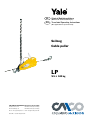
1
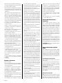
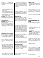
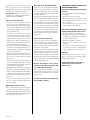
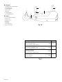
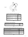
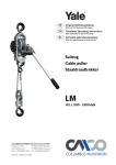
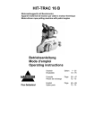
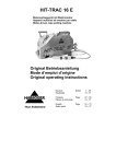
DE
Original Betriebsanleitung
EN
Translated Operating Instructions
(Gilt auch für Sonderausführungen)
(Also applicable for special versions)
Seilzug
Cable puller
LP
W L L 500 kg
Columbus McKinnon Industrial Products GmbH
• D-42513 Velbert, Germany
Postfach 10 13 24
• D-42549 Velbert, Germany
Am Lindenkamp 31
Phone +49 (0) 20 51/600-0 • Fax +49 (0) 20 51/600-127
Ident.-No.: 09901120/03.2012
DE
Seite 2
EN
Page 5
Deutsch
DE
Vorwort
Produkte der CMCO Industrial Products GmbH
sind nach dem Stand der Technik und den
anerkannten gültigen Regeln gebaut. Durch
unsachgemäße Handhabungen können
dennoch bei der Verwendung der Produkte
Gefahren für Leib und Leben des Benutzers
oder Dritter auftreten bzw. Beschädigungen
am Hebezeug oder anderen Sachwerten
entstehen.
Das Bedienpersonal muss vor Arbeitsbeginn
eingewiesen worden sein. Dazu ist die Betriebsanleitung von jedem Bediener vor der
ersten Inbetriebnahme sorgfältig zu lesen.
Diese Betriebsanleitung soll erleichtern, das
Produkt kennenzulernen und die bestimmungsgemäßen Einsatzmöglichkeiten zu
nutzen. Die Betriebsanleitung enthält wichtige
Hinweise, um das Produkt sicher, sachgerecht
und wirtschaftlich zu betreiben. Ihre Beachtung hilft Gefahren zu vermeiden, Reparaturkosten und Ausfallzeiten zu vermindern
und die Zuverlässigkeit und Lebensdauer des
Produktes zu erhöhen. Die Betriebsanleitung
muss ständig am Einsatzort des Produktes
verfügbar sein. Neben der Betriebsanleitung
und den im Verwenderland und an der Einsatzstelle geltenden verbindlichen Regelungen
zur Unfallverhütungsvorschrift sind auch
die anerkannten Regeln für sicherheits- und
fachgerechtes Arbeiten zu beachten.
Das Personal für Bedienung, Wartung oder Reparatur des Produktes muss die Anweisungen
in dieser Betriebsanleitung lesen, verstehen
und befolgen.
Die beschriebenen Schutzmaßnahmen führen
nur dann zu der erforderlichen Sicherheit,
wenn das Produkt bestimmungsgemäß
betrieben und entsprechend den Hinweisen
installiert bzw. gewartet wird. Der Betreiber
ist verpflichtet, einen sicheren und gefahrlosen
Betrieb zu gewährleisten.
2 von 16
Bestimmungsgemässe
Verwendung
- Das Gerät dient dem Heben, Senken,
Ziehen, Spannen und Sichern von Lasten
in beliebiger Lage und Richtung.
Eine andere oder darüber hinausgehende Benutzung gilt als nicht
bestimmungsgemäß. Für hieraus resultierende Schäden haftet Columbus
McKinnon Industrial Products GmbH
nicht. Das Risiko trägt allein der Anwender bzw. Betreiber.
- Die auf dem Gerät angegebene Tragfähigkeit
(WLL) ist die maximale Last, die angeschlagen werden darf.
- Sollte das Hebezeug zum häufigen Ablassen
aus großen Höhen oder im Taktbetrieb eingesetzt werden, ist zuvor mit dem Hersteller
Rücksprache zu halten.
- Die Auswahl und Bemessung der geeigneten
Tragkonstruktion obliegt dem Betreiber.
- Das Hebezeug muss zwischen Anschlagpunkt und Last so eingerichtet werden, dass
es sich frei in Seil- und Zugkraftrichtung
ausrichten kann.
- Beim Einhängen des Gerätes ist vom Bediener darauf zu achten, dass das Hebezeug
so bedient werden kann, dass der Bediener
weder durch das Gerät selbst noch durch
das Tragmittel oder die Last gefährdet wird.
- Der Bediener darf eine Lastbewegung erst
dann einleiten, wenn er sich davon überzeugt
hat, dass die Last richtig angeschlagen ist
und sich keine Personen im Gefahrenbereich
aufhalten.
- Der Aufenthalt unter einer angehobenen Last
ist verboten.
- Lasten nicht über längere Zeit oder unbeaufsichtigt in angehobenem oder gespanntem
Zustand belassen.
- Das Hebezeug kann in einer Umgebungstemperatur zwischen –10 °C und +50 °C
eingesetzt werden.
Bei Extrembedingungen muss mit dem
Hersteller Rücksprache genommen werden.
- Vor dem Einsatz des Hebezeuges in besonderen Atmosphären (hohe Feuchtigkeit,
salzig, ätzend, basisch) oder der Handhabung gefährlicher Güter (z.B. feuerflüssige
Massen, radioaktive Materialien) ist mit dem
Hersteller Rücksprache zu halten.
- Das Umlenken des Zugseils darf nur mit
funktionsfähigen und ausreichend dimensionierten Seilflaschen (Umlenkrollen) erfolgen.
- Bei der Verwendung von Zughaken und/
oder Anschlagseilen oder -ketten, ist auf die
richtige Dimensionierung zu achten.
- Zum Anschlagen einer Last dürfen nur
zugelassene und geprüfte Anschlagmittel
benutzt werden.
- Zur bestimmungsgemäßen Verwendung
gehört neben der Beachtung der Betriebsanleitung auch die Einhaltung der Wartungsanleitung.
- Bei Funktionsstörungen oder abnormalen
Betriebsgeräuschen ist das Hebezeug sofort
außer Betrieb zu setzen.
Sachwidrige Verwendung
(nicht vollständige Auflistung)
- Die Tragfähigkeit des Gerätes (WLL) bzw. des
Tragmittels sowie der Tragkonstruktion darf
nicht überschritten werden.
- Es ist verboten, eine Last in das schlaffe Seil
fallen zu lassen - Gefahr des Seilbruchs!
- Das Entfernen oder Verdecken von Beschriftungen (z.B. durch Überkleben), Warnhinweisen oder dem Typenschild ist untersagt.
- Beim Transport der Last ist eine Pendelbewegung (Fig. 1) und das Anstoßen an
Hindernisse zu vermeiden.
- Die Last darf nicht in Bereiche bewegt werden, die für den Bediener nicht einsehbar
sind. Nötigenfalls hat er sich um Hilfestellung
zu bemühen.
- Motorischer Antrieb des Gerätes ist verboten.
- Eine Hebelverlängerung ist nicht statthaft
(Fig. 2). Es dürfen nur Original-Handhebel
verwendet werden.
- Das Gerät darf niemals mit mehr als der
Kraft einer Person bedient werden.
- Schweißarbeiten an Haken und Seil sind
verboten. Das Seil darf nicht als Erdungsleitung bei Schweißarbeiten verwendet werden
(Fig. 3).
- Schrägzug, d.h. seitliche Belastungen des
Gehäuses und/oder des Lasthakens, ist
verboten (Fig. 4). Immer in einer geraden
Linie zwischen beiden Haken und/oder
Anschlagbolzen heben/ziehen/spannen.
- Nur Original-Anschlagbolzen verwenden
- niemals andere Anschlagmittel (als den
zum Gerät gehörenden Anschlagbolzen) in
die Aufnahmebohrungen einsetzen.
- Ein ohne Rücksprache mit dem Hersteller
verändertes Gerät darf nicht benutzt werden.
- Die Benutzung des Hebezeuges zum Transport von Personen ist verboten (Fig. 5).
- Das Seil darf nicht als Anschlagseil (Schlingseil) verwendet werden (Fig. 6).
- Seil nicht knoten oder mit Seilklemmen,
Schrauben oder Ähnlichem verkürzen
oder verlängern (Fig. 7). Seile dürfen nicht
instandgesetzt werden.
- Das Seil nicht über Kanten ziehen.
- Das Entfernen der Sicherheitsbügel von
Trag- bzw. Lasthaken ist verboten (Fig. 8).
- Hakenspitze nicht belasten (Fig. 9). Das
Anschlagmittel muss immer im Hakengrund
aufliegen.
- Die aufgenommene Last darf sich nicht
drehen, denn das Zugseil und der Lasthaken des Gerätes sind nicht zum Drehen
von angehängten Lasten konzipiert. Ist
ein betriebsmäßiges Drehen vorgesehen,
müssen sog. Drallfänger eingesetzt werden
bzw. es ist mit dem Hersteller Rücksprache
zu halten. Es darf sich keine Drallbildung im
Seil einstellen.
- Es ist darauf zu achten, dass der Anschlagbolzen vollständig durch die Aufnahmen
gesteckt wurde und mit der selbstsichernden
Mutter (Fig. 10) gesichert wurde.
- Sollte die zu ziehende/spannende/hebende
Last mittels eines Hakens am Anschlagbolzen angeschlagen werden, so ist unbedingt
darauf zu achten, dass der Anschlagbolzen
korrekt im Hakengrund aufgenommen wird,
der Haken also nicht zu groß gewählt wurde.
- Beim Einsatz des Gerätes darf das lose
Zugseilende beim Ablassen/Entlasten und
das Hakenende beim Anheben/Ziehen das
Gerät nicht erreichen.
- Das lose Zugseilende darf nicht zum Anschlagen von Lasten verwendet werden.
- Die beiden Aufnahmebohrungen für den Anschlagbolzen dürfen nicht zum Anschlagen
von Haken, Seilen, Ketten oder Bändern
verwendet werden.
- Der Backenöffnungshebel darf nicht betätigt
werden, wenn das Gerät unter Last steht.
- Befindet sich das Hebezeug unter Last, ist
es verboten, den Seilvorschub- und den
Seilrückzughebel gleichzeitig zu betätigen.
- Bei der Verwendung von Zugseilen ist auf die
richtige Dimensionierung zu achten. Es sind
die Grundsätze für Seiltriebe DIN 15020 zu
beachten.
- Mit dem Lastaufnahmemittel darf jeweils nur
eine Last transportiert werden.
- Niemals in bewegliche Teile greifen.
- Gerät nicht aus großer Höhe fallen lassen.
Es sollte immer sachgemäß auf dem Boden
abgelegt werden.
- Das Gerät darf nicht in explosionsfähiger
Atmosphäre eingesetzt werden.
Prüfung vor der ersten
Inbetriebnahme
Vor der ersten Inbetriebnahme, vor der Wiederinbetriebnahme und nach grundlegenden
Änderungen ist das Produkt einschließlich der
Tragkonstruktion einer Prüfung durch eine
befähigte Person* zu unterziehen.
Diese Prüfung besteht im Wesentlichen aus
einer Sicht- und Funktionsprüfung. Diese
Prüfungen sollen sicherstellen, dass sich das
Hebezeug in einem sicheren Zustand befindet,
ordnungsgemäß aufgestellt und betriebsbereit
ist und gegebenenfalls Mängel bzw. Schäden
festgestellt und behoben werden.
*Als befähigte Personen können z.B. die
Wartungsmonteure des Herstellers oder Lieferanten angesehen werden. Der Unternehmer
kann aber auch entsprechend ausgebildetes
Fachpersonal des eigenen Betriebes mit der
Prüfung beauftragen.
ACHTUNG: Beim Umgang mit Drahtseilen
sollten Schutzhandschuhe getragen werden.
Prüfung vor Arbeitsbeginn
Vor jedem Arbeitsbeginn ist das Gerät einschließlich der Tragmittel, Ausrüstung und
Tragkonstruktion auf augenfällige Mängel
und Fehler wie z.B. Verformungen, Anrisse,
Verschleiß und Korrosionsnarben zu überprüfen. Weiterhin sind die Bremse und das
korrekte Einhängen des Gerätes und der Last
zu überprüfen.
Bremsfunktion prüfen
Vor Arbeitsbeginn unbedingt die Funktion der
Bremse prüfen:
Dazu ist mit dem Gerät eine Last über eine
kurze Distanz zu heben, zu ziehen oder zu
spannen und wieder abzusenken bzw. zu
entlasten. Beim Loslassen des Handhebels
muss die Last in jeder beliebigen Position
gehalten werden.
ACHTUNG: Bei Funktionsstörung der Bremse
ist das Gerät sofort außer Betrieb zu setzen
und Rücksprache mit dem Hersteller zu halten!
Überprüfung des Hebezeugs
Auf ausreichende Schmierung der Mechanik
achten. Möglichst vor jedem Arbeitsbeginn
und nötigenfalls auch im Verlauf längerer
Arbeiten die Klemmbackenpaare mit dickflüssigem Motoröl schmieren. Währenddessen
den Seilvorschub- und den Seilrückzughebel
mehrmals bewegen.
Überprüfung des Anschlagpunktes
- Der Anschlagpunkt für das Hebezeug ist so
zu wählen, dass die Tragkonstruktion, an der
es montiert werden soll, eine ausreichende
Stabilität besitzt und die zu erwartenden
Kräfte sicher aufgenommen werden können.
- Es ist dafür zu sorgen, dass sich das Gerät
auch unter Last frei ausrichten kann, da
sonst unzulässige Zusatzbelastungen auftreten können.
- Die Auswahl und Bemessung der geeigneten
Tragkonstruktion obliegt dem Betreiber.
ACHTUNG: Beim Einsatz des Hebezeugs im
Zusammenspiel mit Umlenkrollen (Flaschenzugprinzip) kann ein Mehrfaches des Lastgewichts auf die Tragkonstruktion einwirken!
Überprüfung des Seils
ACHTUNG: Beim Umgang mit Drahtseilen
sollten Schutzhandschuhe getragen werden.
Das Seil muss auf äußere Fehler, Verformungen, Knicke, Brüche einzelner Drähte
oder Litzen, Quetschungen, Aufdoldungen,
Rostschäden (z.B. Korrosionsnarben), starke
Überhitzung und starke Abnutzung der
Seilendverbindungen (z.B. der Presshülse)
überprüft werden. Seilschäden können zu
Funktionsstörungen und bleibenden Schäden
am Seilzug führen. Durch hervorstehende,
gebrochene Seildrähte kann es zu Verletzungen kommen.
Werden bereits leichte (noch nicht zur Ablegereife führende) Beschädigungen festgestellt,
sind die Kontrollabstände zu verkürzen.
Überprüfung des Trag- und Lasthakens
Der Trag- und Lasthaken muss auf Risse,
Verformungen, Beschädigungen, Abnutzung
und Korrosionsnarben überprüft werden. Der
Sicherheitsbügel muss leichtgängig und voll
funktionsfähig sein.
Überprüfung des Anschlagbolzens
Der Anschlagbolzen muss auf Risse, Verformungen, Beschädigungen, Abnutzung und
Korrosionsnarben überprüft werden.
Funktion / Betrieb
Einführung des Drahtseils
- Es dürfen nur Original Yale-Zugseile mit dem
zum Hebezeug passenden Nenndurchmesser verwendet werden.
- Das Zugseil ist immer lagegerecht von der
Haspel abzurollen, um Seilschlingen zu
vermeiden, die zur Beschädigung des Seiles
führen können.
- Seilvorschubhebel und Seilrückzughebel in
vorderste Position (in Richtung Anschlagbolzen) bringen.
- Backenöffnungshebel in Pfeilrichtung
drücken, dass er über die Gehäusewand
gleitet, bis er hör- und spürbar in der
oberen Endposition einrastet (Klemmbacken
geöffnet). Das Umlegen des Backenöffnungshebels geht erheblich leichter, wenn man
das Gerät hochkant auf den Anschlagbolzen
stellt und den Hebel somit nach unten drückt
(Hebel nur per Hand umlegen, niemals mit
einem Hammer schlagen).
- Das angespitzte Ende des Zugseils gemäß
Gerätetyp in die Seileinführungshülse
(Fig. 10) stecken und durch das Klemmbackensystem schieben bis die Arbeitsposition
erreicht ist.
- Den Backenöffnungshebel durch einen
leichten Schlag wieder aus der Endraste
herausdrücken (Vorsicht, Verletzungsgefahr).
Dadurch werden die Klemmbacken geschlossen und das Gerät ist einsatzbereit.
3 von 16
Seilfreischaltung
Durch Betätigen des Backenöffnungshebels
(Fig. 10) werden die Klemmbacken geöffnet
und das Zugseil kann schnell und bequem
vorgespannt sowie nach Beenden der Arbeit
aus dem Gerät gezogen werden.
ACHTUNG: Backenöffnungshebel nur im unbelasteten/ungespannten Zustand betätigen!
Erhöhung der Tragfähigkeit durch Umlenkrollen (z.B. Yale Drahtseilkloben)
Ist die einfache maximale Nenntragfähigkeit
im direkten Zug nicht ausreichend, so kann
sie durch Umlenkrollen/Drahtseilkloben im
Flaschenzugprinzip vervielfacht werden. So
wird die Last auf mehrere Seilstränge verteilt.
Dabei sind folgende Bedingungen zu erfüllen:
- Eine befähigte Person hat die ausreichende
Tragfähigkeit der Umlenkrolle festzustellen.
- Die Umlenkrolle muss eine Vorrichtung haben, die unbeabsichtigtes Öffnen verhindert.
- Die Umlenkrolle muss für denselben
Temperaturbereich ausgelegt sein wie das
Hebezeug.
- Es dürfen nur Haken mit Sicherheitsbügel
verwendet werden.
- Der Durchmesser der Umlenkrolle muss
mindestens das 12fache des Seil-Nenndurchmessers betragen.
- Die Rillentiefe der Umlenkrolle muss mindestens das 1,5fache des Seil-Nenndurchmessers betragen.
- Die Umlenkrolle muss mit einer Seilführungseinrichtung ausgestattet sein, die
sicherstellt, dass das Zugseil auch bei
Schlaffseilbildung in der Umlenkrollenrille
verbleibt.
Heben/Ziehen/Spannen
- Handhebel bzw. Teleskophandhebel auf
Seilvorschubhebel (Fig. 10) stecken und
durch Drehung sichern.
- Pumpbewegungen mit möglichst großem
Hebelweg durchführen.
- Es ist darauf zu achten, dass das Zugseil das
Gerät auf der Anschlagbolzenseite frei und
ungehindert verlassen kann.
- Das unbelastete, freie Seil ist geordnet
am Gerät zu führen (Austritt des Seils am
Anschlagbolzen). Ein ungeordnetes Seil
kann zu Funktionsstörungen führen und ein
Sicherheitsrisiko darstellen.
Senken/Entlasten
- Handhebel bzw. Teleskophandhebel auf
Seilrückzughebel (Fig. 10) stecken und durch
Drehung sichern.
- Senkvorgang durch Pumpbewegungen mit
möglichst großem Hebelweg durchführen.
4 von 16
Überlastsicherung
Um Beschädigungen des Hebezeuges durch
zu große Kräfte zu verhindern, ist die Kraftübertragung vom Vorschubhebel auf das Gerät
durch einen Abscherstift begrenzt. Er schert
bei Überlastung ab. Ein neuer Abscherstift
(im Handhebelgriff bzw. Tragegriff) kann
auch unter Last eingesetzt werden. Dazu die
Stiftreste mit einem Durchschlag entfernen
und neuen Abscherstift mit einem Hammer
vorsichtig einschlagen. Es dürfen nur Original
YALE-Abscherstifte verwendet werden.
Mit abgeschertem Stift ist ein Ab- bzw. Nachlassen der Last weiterhin jederzeit möglich.
Prüfung, Wartung UND REPARATUR
Laut bestehenden nationalen/internationalen
Unfallverhütungs- bzw. Sicherheitsvorschriften
müssen Hebezeuge
•gemäß der Gefahrenbeurteilung des
Betreibers,
•vor der ersten Inbetriebnahme,
•vor der Wiederinbetriebnahme nach
Stilllegung,
•nach grundlegenden Änderungen,
•jedoch mindestens 1 x jährlich durch eine
befähigte Person geprüft werden.
ACHTUNG: Die jeweiligen Einsatzbedingungen (z.B. in der Galvanik) können kürzere
Prüfintervalle notwendig machen.
Reparaturarbeiten dürfen nur von Fachwerkstätten, die Original Yale Ersatzteile verwenden, durchgeführt werden. Die Prüfung (im
Wesentlichen Sicht- und Funktionsprüfung) hat
sich auf die Vollständigkeit und Wirksamkeit
der Sicherheitseinrichtungen sowie auf den
Zustand des Gerätes, der Tragmittel, der
Ausrüstung und der Tragkonstruktion hinsichtlich Beschädigung, Verschleiß, Korrosion
oder sonstigen Veränderungen zu erstrecken.
Die Inbetriebnahme und die wiederkehrenden
Prüfungen müssen dokumentiert werden (z.B.
in der CMCO-Werksbescheinigung).
Auf Verlangen sind die Ergebnisse der Prüfungen und die sachgemäße Reparaturdurchführung nachzuweisen. Ist das Hebezeug (ab 1 t
Hubgewicht) an oder in einem Handfahrwerk
eingebaut, oder wird mit dem Hebezeug
eine gehobene Last in eine oder mehrere
Richtungen bewegt, wird die Anlage als Kran
betrachtet und es sind ggf. weitere Prüfungen
durchzuführen.
Lackbeschädigungen sind auszubessern, um
Korrosion zu vermeiden. Alle Gelenkstellen
und Gleitflächen sind leicht zu schmieren.
Bei starker Verschmutzung ist das Gerät zu
reinigen.
Spätestens nach 10 Jahren muss das Gerät
einer Generalüberholung unterzogen werden.
Insbesondere die Maße des Drahtseils und des
Last- bzw. Traghakens und des Anschlagbolzens bedürfen der Beobachtung. Sie sind mit
den Tabellenmaßen (Tab. 1 - 3) zu vergleichen.
ACHTUNG: Der Austausch von Bauteilen
zieht zwangsläufig eine anschließende Prüfung
durch eine befähigte Person nach sich!
Prüfung des Drahtseils
- Das Seil muss auf äußere Fehler, Verformungen, Knicke, Brüche einzelner Drähte
oder Litzen, Quetschungen, Aufdoldungen,
Rostschäden (z.B. Korrosionsnarben), starke
Überhitzung und starke Abnutzung der
Seilendverbindungen (z.B. der Presshülse)
überprüft werden.
- Aus Sicherheitsgründen muss ein Drahtseil
ausgewechselt werden, wenn die Drahtbrüche in den Außenlitzen eine vorgegebene
Anzahl übersteigt. Gezählt wird über eine
Seillänge von 11- bzw. 30- mal dem Seildurchmesser. Die maximal erlaubte Anzahl
gebrochener Litzen ist Tab. 4 zu entnehmen.
- Das Drahtseil muss sofort ausgewechselt
werden, wenn eine Litze vollständig gebrochen, das Seil verformt, geknickt, gestaucht
oder in irgendeiner anderen Weise beschädigt oder verschlissen ist!
- Das Drahtseil hat die Ablegereife erreicht,
wenn sich durch Strukturveränderungen der
Seildurchmesser auf längeren Strecken um
10 % oder mehr gegenüber dem Nennmaß
verringert hat.
- Ebenso hat das Drahtseil die Ablegereife
erreicht, wenn es sich (auch stellenweise)
nur mit erhöhtem Kraftaufwand durch die
Klemmbacken des Hebezeuges schieben/
ziehen läßt.
- Maßgebend für die Wartung und Prüfung
des Drahtseiles sind die DIN 15020 Blatt 2
“Grundsätze für Seiltriebe, Überwachung
und Gebrauch”, sowie die gültigen nationalen und internationalen Vorschriften des
Betreiberlandes.
- Ein ablegereifes Drahtseil ist durch ein
Drahtseil gleicher Abmessungen und Güte
zu ersetzen.
Wartung des Drahtseils
Das Drahtseil ist über seine gesamte Länge
(also auch der Teil, der sich gerade im Hebezeug oder im Lastaufnahmemittel befindet)
am Ende eines Einsatztages von grobem
Schmutz zu befreien und erneut leicht einzufetten, um Korrosion vorzubeugen.
Prüfung des Trag- und Lasthakens
Die Prüfung der Haken auf Verformung, Beschädigungen, Oberflächenrisse, Abnutzung
und Korrosion ist nach Bedarf, jedoch mindestens einmal im Jahr durchzuführen. Die
jeweiligen Einsatzbedingungen können auch
kürzere Prüfintervalle erforderlich machen.
Haken, die laut Prüfung verworfen wurden,
sind durch neue zu ersetzen. Schweißungen
an Haken, z.B. zum Ausbessern von Abnutzung sind nicht zulässig. Trag- und/oder
Lasthaken müssen ausgewechselt werden,
wenn die Maulöffnung um 10% aufgeweitet
ist (Fig. 11) oder wenn die Nennmaße durch
Abnutzung um 5% abgenommen haben.
Nennwerte und Verschleißgrenzen sind der
nachstehenden Tabelle 2 zu entnehmen. Bei
Erreichen der Grenzwerte sind die Bauteile
auszuwechseln.
Prüfung des Anschlagbolzens
Die Prüfung des Anschlagbolzens auf Verformung, Beschädigungen, Oberflächenrisse,
Abnutzung und Korrosion ist nach Bedarf,
jedoch mindestens einmal im Jahr durchzuführen. Die jeweiligen Einsatzbedingungen
können auch kürzere Prüfintervalle erforderlich machen.
Ein Anschlagbolzen, der laut Prüfung verworfen wurde, ist durch einen Neuen zu ersetzen.
Schweißungen am Anschlagbolzen, z.B. zum
Ausbessern von Abnutzung, sind nicht zulässig. Der Anschlagbolzen ist spätestens dann
zu ersetzen, wenn sein Durchmesser um 5 %
kleiner als der Nenndurchmesser (Tab. 3) ist.
Reparaturen dürfen nur von autorisierten Fachwerkstätten, die Original YaleErsatzteile verwenden, durchgeführt
werden.
Nach einer erfolgten Reparatur sowie nach
längerer Standzeit ist das Hebezeug vor der
Wiederinbetriebnahme erneut zu prüfen.
Die Prüfungen sind vom Betreiber zu
veranlassen.
Transport, Lagerung, AuSSerbetriebnahme und Entsorgung
Beim Transport des Gerätes sind folgende Punkte zu beachten:
•Gerät nicht stürzen oder werfen, immer
vorsichtig absetzen.
•Zugseil aus dem Gerät entfernen.
•Das Drahtseil ist so zu transportieren, dass
sie sich nicht verknoten kann und sich
keine Schlaufen bilden können (z.B. auf
einer Haspel).
•Geeignete Transportmittel verwenden.
Diese richten sich nach den örtlichen
Gegebenheiten.
Bei der Lagerung oder der vorübergehenden Außerbetriebnahme des Gerätes sind folgende Punkte zu beachten:
•Das Gerät an einem sauberen und trockenen Ort lagern.
•Das Gerät inkl. aller Anbauteile vor Verschmutzung, Feuchtigkeit und Schäden
durch eine geeignete Abdeckung schützen.
•Haken vor Korrosion schützen.
•Das Seil ist durch Einfetten vor Korrosion
zu schützen.
•Soll das Gerät nach der Außerbetriebnahme
wieder zum Einsatz kommen, ist es zuvor
einer erneuten Prüfung durch eine befähigte
Person zu unterziehen.
Entsorgung:
Nach Außerbetriebnahme sind die Teile
des Gerätes entsprechend den gesetzlichen
Bestimmungen der Wiederverwertung zuzuführen bzw. zu entsorgen.
Weitere Informationen und Betriebsanleitungen zum Download sind unter
www.cmco.eu zu finden!
English
EN
Introduction
Products of CMCO Industrial Products GmbH
have been built in accordance with the stateof-the-art and generally accepted engineering
standards. Nonetheless, incorrect handling
when using the products may cause dangers
to life and limb of the user or third parties
and/or damage to the hoist or other property.
The operating company is responsible for
the proper and professional instruction of
the operating personnel. For this purpose, all
operators must read these operating instructions carefully prior to the initial operation.
These operating instructions are intended to
acquaint the user with the product and enable
him to use it to the full extent of its intended
capabilities. The operating instructions contain
important information on how to operate the
product in a safe, correct and economic way.
Acting in accordance with these instructions
helps to avoid dangers, reduce repair costs
and downtimes and to increase the reliability
and lifetime of the product. The operating
instructions must always be available at the
place where the product is operated. Apart
from the operating instructions and the accident prevention act valid for the respective
country and area where the product is used,
the commonly accepted regulations for safe
and professional work must also be adhered
to. The personnel responsible for operation,
maintenance or repair of the product must
read, understand and follow these operating
instructions.
The indicated protective measures will only
provide the necessary safety, if the product
is operated correctly and installed and/or
maintained according to the instructions. The
operating company is committed to ensure
safe and trouble-free operation of the product.
Correct operation
- The unit is used for lifting, lowering, pulling,
tensioning and securing of loads in any
position and any direction.
- Any different or exceeding use is considered incorrect. Columbus McKinnon Industrial Products GmbH will not
accept any liability for damage resulting from such use. The risk is borne by
the user or operating company alone.
- The load capacity indicated on the unit is the
maximum working load limit (WLL) that may
be attached.
- If the hoist is to be used for frequent lowering
from large heights or in indexed operation,
first consult the manufacturer for advice.
5 von 16
- The selection and calculation of the appropriate supporting structure are the responsibility of the operating company.
- The hoist must be arranged between attachment point and load in such a way that it can
freely align in the direction of the rope and
pulling force.
- The operator must ensure that the hoist is
suspended in a manner that makes it possible to operate the unit without exposing
himself or other personnel to danger by the
unit itself, the suspension or the load.
- The operator may start moving the load only
after it has been attached correctly and all
persons are clear of the danger zone.
- Do not allow personnel to stay or pass under
a suspended load.
- A lifted or clamped load must not be left
unattended or remain lifted or clamped for
a longer period of time.
- The hoist may be used at ambient temperatures between –10 °C and +50 °C.
Consult the manufacturer in the case of
extreme working conditions.
- Prior to operation of the hoist in special
atmospheres (high humidity, salty, caustic,
alkaline) or handling hazardous goods (e.g.
molten compounds, radioactive materials),
consult the manufacturer for advice.
- The rope must only be returned by means of
fully functional and sufficiently dimensioned
rope pulleys (return pulleys).
- When hooks and/or rope slings or chains
are used, it must be ensured that they are
correctly dimensioned.
- For attaching a load, only approved and
certified lifting tackle must be used.
- Correct operation involves compliance with
the operating instructions and in addition
also compliance with the maintenance
instructions.
- In case of functional defects or abnormal
operating noise, stop using the hoist immediately.
Incorrect operation
(List not complete)
- Do not exceed the rated load capacity (WLL)
of the unit and/or the suspension and the
supporting structure.
- It is prohibited to allow the load to fall into
the slack rope – danger of rope rupture!
- Removing or covering (e.g. by adhesive
labels) labels, warning information signs or
the identity plate is prohibited.
- When transporting loads ensure that the load
does not swing (Fig. 1) or come into contact
with other objects.
- The load must not be moved into areas which
are not visible to the operator. If necessary,
6 von 16
he must ensure he is given help.
- Driving the unit with a motor is not allowed.
- The lever must not be extended (Fig. 2). Only
original hand levers must be used.
- The unit must never be operated with more
than the power of a person.
- Welding on hook and rope is strictly forbidden. The rope must never be used as a
ground connection during welding (Fig. 3).
- Side pull, i. e. side loading of the housing
and/or the load hook (Fig. 4) is forbidden.
Always lift/pull/tension within a straight line
between both hooks and/or anchor bolts.
- Only use original anchor bolts – never insert
any other lifting tackle (than the anchor bolt
which belongs to the unit) into the mounting
holes.
- A unit changed without consulting the
manufacturer must not be used.
- Do not use the hoist for the transportation
of people (Fig. 5).
- The rope must not be used as a rope sling
(Fig. 6).
- Do not tie knots in the rope or extend or
shorten it by using rope clamps, screws or
similar (Fig. 7). Ropes must not be repaired.
- Do not pull the rope over edges.
- Removing the safety latches from top resp.
load hooks is forbidden (Fig. 8).
- Never attach the load to the tip of the hook
(Fig. 9). The lifting tackle must always be
seated in the saddle of the hook.
- The load must not be allowed to revolve
around its own axis, since the rope and the
load hook of the unit have not been designed
for turning attached loads. If loads must be
turned in normal operation, an anti-twist
swivel must be used or the manufacturer
must be consulted. The rope must not twirl.
- Make sure that the anchor bolt has been
fully pushed through the mounting holes and
secured with the self-locking nut (Fig. 10).
- If the load to be pulled/tensioned/lifted is
attached to the anchor bolt by means of a
hook, always make sure that the anchor bolt
is correctly seated in the saddle of the hook,
i.e. the hook size selected is not too large.
- When the unit is in operation, the loose end
of the rope must not reach the unit while
lowering/unloading; the hook end must not
reach it while lifting/pulling.
- The loose end of the rope must not be used
for attaching loads.
- The two mounting holes for the anchor bolt
must not be used for attaching hooks, ropes,
chains or belts.
- The clamping jaw lever must not be actuated,
when the unit is under load.
- If the hoist is under load, it is prohibited to
actuate the forward lever and the reversing
lever at the same time.
- When ropes are used, it must be ensured
that they are correctly dimensioned. The
principles laid down in DIN 15020 for rope
drive arrangements must be complied with.
- Only one load may be transported at a time
with the load lifting attachment.
- Never reach into moving parts.
- Do not allow the unit to fall from a large
height. Always place it properly on the
ground.
- The unit must not be used in potentially
explosive atmospheres.
Inspection before initial
operation
Prior to initial operation, before it is put
into operation again and after substantial
changes, the product including the supporting
structure must be inspected by a competent
person*. The inspection mainly consists of a
visual inspection and a function check. These
inspections are intended to establish that the
hoist is in a safe condition, has been set up
appropriately and is ready for operation and
that any defects or damage are detected and
eliminated, as required.
*Competent persons may be, for example, the
maintenance engineers of the manufacturer or
the supplier. However, the company may also
assign performance of the inspection to its
own appropriately trained specialist personnel.
ATTENTION: Always wear protection gloves
for handling wire ropes.
Inspections before starting
work
Before starting work, inspect the unit including
the suspension, equipment and supporting
structure for visual defects, e. g. deformations,
damage, cracks, wear and corrosion marks.
In addition also test the brake and check that
the hoist and the load are correctly attached.
Checking the brake function
Before starting work, always check operation
of the brake:
To do this, lift, pull or tension and lower or
release a load over a short distance with the
unit. When the hand lever is released, the load
must be held in any position.
ATTENTION: If the brake does not function
properly, the unit must be immediately taken
out of service and the manufacturer must
be contacted!
Inspection of the hoist
Make sure the mechanical equipment is sufficiently lubricated. Each time before starting
work and, if necessary, also in the course of
longer work, lubricate the clamping jaw pairs
with thick motor oil. Actuate the forward
lever and the reversing lever several times
for lubricating.
Inspection of the attachment point
- The attachment point for the hoist must be
selected so that the supporting structure to
which it is to be fitted has sufficient stability
and to ensure that the expected forces can
be safely absorbed.
- The unit must align freely also under load
in order to avoid impermissible additional
loading.
- The selection and calculation of the appropriate supporting structure are the responsibility of the operating company.
ATTENTION: When the hoist is used in
combination with return pulleys (pulley block
principle), a multiple of the load weight may
act on the supporting structure!
Inspection of the rope
ATTENTION: Always wear protection gloves
for handling wire ropes.
Check the rope for outer defects, deformations, kinks, broken individual wires or strands,
crushing, swelling, rust damage (e.g. corrosion
marks), strong overheating and heavy wear
of the rope end connections (e.g. pressure
sleeve). Rope damage may result in malfunctions and lasting damage to the cable puller.
Protruding, broken wires may cause injuries.
If slight damage (not yet resulting in discarding of the rope) is determined, the inspection
intervals must be shortened.
Inspection of the top hook and load hook
The top and load hooks must be checked
for cracks, deformations, damage, wear and
corrosion marks. The safety latch must move
freely and be fully functioning.
Inspection of the anchor bolt
The anchor bolt must be checked for cracks,
deformations, damage, wear and corrosion
marks.
Function / OPERATION
Inserting the wire rope
- Only original Yale ropes with the nominal
diameter suitable for the hoist may be used.
- Always roll out the rope from the reel in the
correct position, in order to avoid rope slings
which may result in damage to the rope.
- Place the forward and reversing levers in the
front position (in the direction of the anchor
bolt).
- Push the clamping jaw lever in the direction
of the arrow, so that it passes over the housing body, until you hear it noticeably snaps
into the upper end position (clamping jaws
open). To facilitate movement of the clamping jaw lever, position the unit upright on the
anchor bolt and thus push down the lever
(only move the lever by hand, never hit with
a hammer).
- Enter the pointed end of the wire rope according to the model type into the rope entry
sleeve (Fig. 10), slide it through the clamping
jaws and feed it through until the working
position is reached.
- Push the clamping jaw lever out of the
lock again by striking it with a slight stroke
(Caution: danger of injury). This closes the
clamping jaws and the unit is ready for
operation.
Releasing the rope
Actuate the clamping jaw lever (Fig. 10) to
open the clamping jaws; the rope can be
tensioned easily and quickly and also be pulled
out of the unit when work has been completed.
ATTENTION: Only actuate the clamping jaw
lever in no-load/no-tension condition!
Increasing the load capacity by return
pulleys (e.g. Yale wire rope blocks)
If the single max. nominal load capacity in
direct pull is not sufficient, it can be multiplied
by the use of return pulleys/wire rope blocks
based on the pulley block principle. The load is
then distributed to several rope falls.
The following requirements must be fulfilled:
- A competent person must establish that
the load capacity of the return pulley is
adequate.
- The return pulley must be provided with a
device which prevents unintended opening.
- The return pulley must be rated for the same
temperature range as the hoist.
- Only use hooks with a safety latch.
- The diameter of the return pulley must be at
least 12 times the nominal rope diameter.
- The groove depth of the return pulley must be
at least 1.5 times the nominal rope diameter.
- The return pulley must be provided with a
rope guide ensuring that the rope remains
in the groove of the return pulley also in the
event of slack rope.
Lifting/pulling/tensioning
- Place the (telescopic) handle over the forward lever (Fig. 10) and rotate till it engages.
- Operate the unit with a pumping action,
where possible use full strokes.
- Make sure that the rope can leave the unit
on the anchor bolt side freely and without
any obstruction.
- Guide the unloaded free rope on the unit
(exit of rope on anchor bolt). An insufficiently
guided rope may lead to malfunctions and
represent a safety risk.
Lowering/unloading
- Place the (telescopic) handle over the reverse
movement lever (Fig. 10) and rotate till it
engages.
- Operate the unit for lowering with a pumping
action, where possible use full strokes.
Overload protection
In order to avoid damage to the hoist by
excessive forces, the transmission of power
from the forward lever to the unit is limited by
means of a shear pin. It shears when overload
is applied. A new shear pin (stored in the
carrying handle or lever grip) can also be fitted
under load. To do this, remove pin remainders
with a drift and carefully drive in the new shear
pin using a hammer. Only original Yale shear
pins must be used.
Lowering of the load is always still possible
with shorn pin.
Inspection, maintenance AND
REPAIR
According to national and international accident prevention and safety regulations hoisting
equipment must be inspected:
•in accordance with the risk assessment of
the operating company,
•prior to initial operation,
•before the unit is put into service again
following a shut down,
•after substantial changes,
•however, at least once per year, by a
competent person.
ATTENTION: Actual operating conditions
(e.g. operation in galvanizing facilities) can
dictate shorter inspection intervals.
Repair work may only be carried out by a specialist workshop that uses original Yale spare
parts. The inspection (mainly consisting of a
visual inspection and a function check) must
determine that all safety devices are complete
and fully operational and cover the condition
of the unit, suspension, equipment and supporting structure with regard to damage, wear,
corrosion or any other alterations.
Initial operation and recurring inspections
must be documented (e.g. in the CMCO works
certificate of compliance).
If required, the results of inspections and
appropriate repairs must be verified. If the
hoist (from 1 t lifting weight) is fitted on or in
a trolley and the hoist is used to move a lifted
load in one or several directions, the installation is considered to be a crane and the further
inspections must be carried out if applicable.
Paint damage should be touched up in order to
avoid corrosion. All joints and sliding surfaces
should be slightly greased. In the case of heavy
contamination, the unit must be cleaned.
The unit must be given a general overhaul
after 10 years, at the latest.
7 von 16
In particular, check the dimensions of the
wire rope, the load resp. top hook and the
supporting pin. They must be compared with
the dimensions specified in the table 1 - 3.
ATTENTION: After the replacement of
components, a subsequent inspection by a
competent person is obligatory!
Inspection of the wire rope
- Check the rope for outer defects, deformations, kinks, broken individual wires or
strands, crushing, swelling, rust damage
(e.g. corrosion marks), strong overheating
and heavy wear of the rope end connections
(e.g. pressure sleeve).
- For safety reasons, wire ropes must be
replaced when the number of broken wires
in the outer strands exceeds a defined
quantity. This is counted over a reference
length of rope 11 times or 30 times the rope
diameter. The max. permissible number of
broken strands is specified in Tab. 4.
- The wire rope must be replaced immediately,
if a strand is completely broken, the rope is
deformed, kinked, compressed or damaged
or worn in any other way!
- The wire rope must be discarded, if the rope
diameter has reduced on longer sections by
10 % or more compared with the nominal
dimension.
- The wire rope must also be discarded, if it
can only be pushed/pulled with increased
effort through the clamping jaws of the hoist
(even if only at certain points).
- DIN 15020 sheet 2 “Principles Relating to
Rope Drives; Supervision during Operation”
and the relevant international and national
regulations of the country of use are definitive for the maintenance and inspection of
wire ropes.
- A worn wire rope must be replaced by a
wire rope with the same dimensions and
the same quality.
Maintenance of the wire rope
At the end of the working day, clean the wire
rope from coarse dirt over its entire length (i.e.
including the part which is in the hoist or in the
load lifting attachment) and slightly regrease
it in order to prevent corrosion.
8 von 16
Inspection of the top and load hook
Inspect the hook for deformation, damage,
surface cracks, wear and signs of corrosion,
as required, but at least once a year. Actual
operating conditions may also dictate shorter
inspection intervals.
Hooks that do not fulfil all requirements must
be replaced immediately. Welding on hooks,
e.g. to compensate for wear or damage is
not permissible. Top and/or load hooks must
be replaced when the mouth of the hook has
opened more than 10 % (Fig. 11) or when the
nominal dimensions have reduced by 5 % as
a result of wear. Nominal dimensions and
wear limits are shown in the following table 2.
If the limit values are exceeded, replace the
components.
Inspection of the anchor bolt
Inspect the anchor bolt for deformation,
damage, surface cracks, wear and signs of
corrosion as required but at least once a year.
Actual operating conditions may also dictate
shorter inspection intervals.
If an anchor bolt must be discarded as a result
of the inspection, a new anchor bolt must be
fitted. Welding on anchor bolts, e.g. to compensate for wear or damage is not permissible.
The anchor bolt must be replaced at the latest,
if its material diameter is 5% smaller than the
nominal diameter (Tab. 3).
Repairs may only be carried out by
authorized specialist workshops that
use original Yale spare parts.
After repairs have been carried out and
after extended periods of non-use, the hoist
must be inspected again before it is put into
service again.
The inspections have to be initiated by
the operating company.
Transport, Storage, take out of
service and Disposal
Observe the following for transporting
the unit:
•Do not drop or throw the unit, always deposit
it carefully.
•Remove the rope from the unit.
•Wire ropes must be transported in a way
to avoid knotting and formation of loops
(e.g. on a reel).
•Use suitable transport means. These
depend on the local conditions.
Observe the following for storing or temporarily taking the unit out of service:
•Store the unit at a clean and dry place.
•Protect the unit incl. all accessories against
contamination, humidity and damage by
means of a suitable cover.
•Protect hooks against corrosion.
•Protect the rope against corrosion by
greasing.
•If the unit is to be used again after it has
been taken out of service, it must first be
inspected again by a competent person.
Disposal:
After taking the unit out of service, recycle or
dispose of the parts of the unit in accordance
with the legal regulations.
Further information and operating
instructions are to be found at
www.cmco.eu
DE
EN
FR
Sachwidrige Verwendung
Incorrect operation
Utilisations incorrectes
Fig. 1
Fig. 2
Fig. 3
Fig. 4
Fig. 5
Fig. 6
Fig. 7
Fig. 8
Fig. 9
9 von 16
Beschreibung
1 Traghaken mit Sicherheitsbügel
2 Anschlagbolzen
3 Seilvorschubhebel
4 Abscherstift
5 Gehäuse
6 Seilrückzughebel
7 Seileinführungshülse
3
6
5
1
4
2
Description
1 Top hook with safety latch
2 Anchor bolt
3 Forward lever
4 Shear pin
5 Housing
6 Reversing lever
7 Rope entry sleeve
7
Fig. 10
Modell / Model / Modèle
LP 500
Tragfähigkeit (Nennlast)
Lifting capacity (rated load)
Capacité de levage (charge nominale)
Seilvorschub pro Doppelhub unbelastet
Rope advance per full stroke cycle
Avance par manipulation av./ar. du levier sans charge
Hebelkraft bei Nennlast
Lever pull at rated load
Effort sur le levier à charge nominale
Seildurchmesser
dnom.
Wire rope diameter
d
min.
Diamètre du câble
Tab. 1
10 von 16
[kg]
500
[mm]
35
[daN]
15
[mm]
8,3
[mm]
7,5
a
h
Fig. 11
b
Hakenmaße / Hook dimensions / Dimensions du crochet
LP
LP 500
Hakenöffnungsmaß / Hook opening
Ouverture du crochet
anom. [mm]
amax. [mm]
14,5
16,0
Maß Hakenbreite / Hook width
Largeur du crochet
bnom. [mm]
bmin. [mm]
16,0
15,2
Maß Hakendicke / Hook height
Hauteur du crochet
hnom. [mm]
hmin. [mm]
21,5
20,4
Tab. 2
Anschlagbolzenmaße / Anchor bolt dimensions
LP
LP 500
Anschlagbolzendurchmesser / Anchor bolt diameter
dnom.
[mm]
17,0
Anschlagbolzendurchmesser / Anchor bolt diameter
dmin.
[mm]
16,2
Tab. 3
Anzahl der sichtbaren Drahtbrüche bei Ablegereife/Discard number of wire breaks
LP
Seildurchmesser d / Rope diameter d
Seilaufbau / Cross section
Mindest-Bruchkraft / Min. breaking load
[mm]
[kN]
Anzahl der sichtbaren Drahtbrüche bei Ablegereife auf einer Länge von 6d
Discard number of wire breaks per 6d
Anzahl der sichtbaren Drahtbrüche bei Ablegereife auf einer Länge von 30d
Discard number of wire breaks per 30d
LP 500
8,3
6x19S-IWRC 1470 sZ
34,3
3
6
Tab. 4
11 von 16
12 von 16
13 von 16
14 von 16
DE
Original EG Konformitätserklärung 2006/42/EG (Anhang II A)
Hiermit erklären wir, dass das nachstehend bezeichnete Produkt in seiner Konzipierung und Bauart sowie in der von uns in Verkehr gebrachten
Ausführung den einschlägigen grundlegenden Sicherheits- und Gesundheitsanforderungen der EG-Richtlinien Maschinen entspricht.
Bei einer nicht mit uns abgestimmten Änderung/Ergänzung des Produktes verliert diese EG-Konformitätserklärung ihre Gültigkeit. Weiterhin
verliert diese EG-Konformitätserklärung ihre Gültigkeit, wenn das Produkt nicht entsprechend den in der Betriebsanleitung aufgezeigten
bestimmungsgemäßen Einsatzfällen eingesetzt wird und die regelmäßig durchzuführenden Überprüfungen nicht ausgeführt werden.
Produkt:
Handhebezeug (Seilzug)
Typ:
Seilzug LP
LP 500
Serien-Nr.:
Seriennummern für die einzelnen Geräte werden archiviert
Tragfähigkeit: 500 kg
Einschlägige EG-Richtlinien: EG-Maschinenrichtlinie 2006/42/EG
Angewandte Normen:
ISO 12100:2010; EN 349:1993+A1:2008; DIN 15020-2:1974; DIN 15400:1990; DIN 15404-1:1989;
BGV D 8; BGR 500
Qualitätssicherung:
EN ISO 9001:2008
Firma / Dokumentationsbevollmächtigter: Columbus McKinnon Industrial Products GmbH
Am Lindenkamp 31, 42549 Velbert, Germany
EN
Datum / Hersteller-Unterschrift:
20.03.2012
Angaben zum Unterzeichner:
Dipl.-Ing. Andreas Oelmann
Leiter Qualitätswesen
Translation of the original EC Declaration of Conformity 2006/42/EC (Appendix II A)
We hereby declare, that the design, construction and commercialised execution of the below mentioned products comply with the essential
health and safety requirements of the EC Machinery Directive.
The validity of this declaration will cease in case of any modification of or supplement to the products without our prior consent. Furthermore, validity of this EC declaration of conformity will cease in case that the products are not operated correctly and in accordance with the
operating instructions and/or not inspected regularly.
Product:
Hand hoist (Cable puller)
Type:
Cable puller LP
LP 500
Serial no.:
Serial numbers for the individual units are recorded
Relevant EC Directives:
EC Machinery Directive 2006/42/EC
Standards in particular:
ISO 12100:2010; EN 349:1993+A1:2008; DIN 15020-2:1974; DIN 15400:1990; DIN 15404-1:1989;
BGV D 8; BGR 500
Quality assurance:
EN ISO 9001:2008
Capacity: 500 kg
Company / Authorised representative for technical data: Columbus McKinnon Industrial Products GmbH
Am Lindenkamp 31, 42549 Velbert, Germany
15 von 16
Germany
United Kingdom
Spain and Portugal
COLUMBUS McKINNON
Industrial Products GmbH*
COLUMBUS McKINNON Corporation Ltd.
COLUMBUS McKINNON Ibérica S.L.U.
Knutsford Way, Sealand Industrial Estate
Chester CH1 4NZ
Phone: 00 44 (0) 1244375375
Web Site: www.cmco.eu
E-mail: [email protected]
Ctra. de la Esclusa, 21 acc. A
41011 Sevilla
Phone: 00 34 954 29 89 40
Web Site: www.yaleiberica.com
E-mail: [email protected]
Unit 1A, The Ferguson Centre
57-59 Manse Road
Newtownabbey BT36 6RW
Northern Ireland
Phone: 00 44 (0) 28 90 840697
Web Site: www.cmco.eu
E-mail: [email protected]
South Africa
COLUMBUS McKINNON
Engineered Products GmbH*
Am Silberpark 2-8
86438 Kissing
Phone: 00 49 (0) 8233 2121-800
Web Site: www.cmco.eu
Web Site: www.pfaff-silberblau.com
E-Mail: [email protected]
Italy
COLUMBUS McKINNON Italia S.r.l.
Via P. Picasso, 32
20025 Legnano (MI)
Phone: 00 39 (0) 331/57 63 29
Web Site: www.cmco.eu
E-mail: [email protected]
Dubai
COLUMBUS McKINNON
Industrial Products ME FZE
Warehouse No. FZSBD01
P.O. Box 261013
Jebel Ali
Dubai, U.A.E.
Phone: 00 971 4 880 7772
Web Site: www.cmco.eu
E-mail: [email protected]
Netherlands
COLUMBUS McKINNON Benelux B.V.*
Grotenoord 30
3341 LT Hendrik Ido Ambacht
Phone: 00 31 (0) 78/6 82 59 67
Web Site: www.yaletakels.nl
E-mail: [email protected]
China
Hangzhou LILA
Lifting and Lashing Co. Ltd.*
Austria
3350 Nanhuan Road, Zhijiang Industrial Park
Hangzhou High-tech Zone
Zhejiang Province
Phone: 00 86 10 85 23 63 86
Web Site: www.yale-cn.com
E-mail: [email protected]
Gewerbepark, Wiener Straße 132a
2511 Pfaffstätten
Phone: 00 43 (0) 22 52/4 60 66-0
Web Site: www.yale.at
E-mail: [email protected]
COLUMBUS McKINNON (Hangzhou)*
Industrial Products Co. Ltd.
COLUMBUS McKINNON Austria GmbH*
Poland
COLUMBUS McKINNON Polska Sp. z o.o.
No. 100 Luofeng Road
Xiaoshan, Yiqiao, Zhejiang Province
Postcode 311256
Phone: 00 86 10 85 23 63 86
Web Site: www.yale-cn.com
E-mail: [email protected]
Ul. Owsiana 14
62-064 PLEWISKA
Phone: 00 48 (0) 61 6 56 66 22
Web Site: www.pfaff.info.pl
E-Mail: [email protected]
France
COLUMBUS McKINNON Russia LLC
Russia
COLUMBUS McKINNON France SARL*
Zone Industrielle des Forges
18108 Vierzon Cedex
Phone: 00 33 (0) 248/71 85 70
Web Site: www.cmco-france.com
E-mail: [email protected]
Chimitscheski Pereulok, 1, Lit. AB
Building 72, Office 33
198095 St. Petersburg
Phone: 007 (812) 322 68 38
Web Site: www.yale.de
E-mail: [email protected]
CMCO Material Handling (Pty) Ltd.*
P.O. Box 15557
Westmead, 3608
Phone: 00 27 (0) 31/700 43 88
Web Site: www.yale.co.za
E-mail: [email protected]
Yale Engineering Products (Pty) Ltd.
12 Laser Park Square, 34 Zeiss Rd.
Laser Park Industrial Area, Honeydew
Phone: 00 27 (0) 11/794 29 10
Web Site: www.yalejhb.co.za
E-mail: [email protected]
Yale Lifting & Mining Products (Pty) Ltd.
P.O. Box 592
Magaliesburg, 1791
Phone: 00 27 (0) 14/577 26 07
Web Site: www.yale.co.za
E-mail: [email protected]
Thailand
Yale Industrial Products Asia Co. Ltd.
54 BB.Building, Room No. 1510, 15th Floor,
Sukhumvit 21 (Asoke) Road, Klongtoey Nua
Wattana, Bangkok 10110
Phone: 00 66 (0) 26 64 03 00
Web Site: www.yale-thailand.com
Turkey
COLUMBUS McKINNON
Kaldırma Ekip. San. ve Tic. Ltd. Şti.
Davutpaşa Caddesi Emintaş
Davutpaşa Matbaacılar Sitesi No. 103/233-234
34010 Topkapi-istanbul
Phone: 00 90 (212) 210 7 555
Web Site: www.cmco.eu
Hungary
COLUMBUS McKINNON Hungary Kft.
Vásárhelyi út 5. VI ép
8000 Székesfehérvár
Phone: 00 36 (22) 546-720
Web Site: www.yale.de
E-mail: [email protected]
Switzerland
COLUMBUS McKINNON Switzerland AG
Dällikerstraße 25
8107 Buchs ZH
Phone: 00 41 (0) 44 8 51 55 77
Web Site: www.cmco.ch
E-mail: [email protected]
*Diese Niederlassungen gehören der Matrix-Zertifizierung nach EN ISO 9001:ff an.
*These subsidiaries belong to the matrix-certification-system according to EN ISO 9001:ff.
Reproduktionen, gleich welcher Art, nur mit schriftlicher Genehmigung der COLUMBUS McKINNON Industrial Products GmbH!
Reproduction of any kind, only with written authorisation of COLUMBUS McKINNON Industrial Products GmbH!
Technische Änderungen vorbehalten. Keine Gewährleistung für Druckfehler oder Irrtümer – Subject to engineering changes and improvements. No warranty for printing errors or mistakes.
Am Lindenkamp 31
42549 Velbert
Phone: 00 49 (0) 20 51/600-0
Web Site: www.cmco.eu
Web Site: www.yale.de
E-mail: [email protected]