1
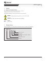
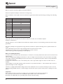
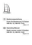
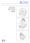
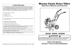
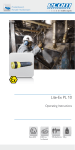
AX-EX
Montage- und Betriebsanleitung Axialventilatoren /
Assembly and Operating Instructions for Axial-Fans
AX-EX (deutsch)
Inhaltsverzeichnis
1
2
Allgemeines
3
1.1 Hinweise zum Verwenden der Dokumentation
3
2
3
Technische Daten
2.1 Typenschild
4
2.2 Daten des Ventilators
4
2.3 Daten des Motors
5
2.4 Elektrische Anschlüsse
5
3
Bestimmungsgemäße Verwendung
5
4
Personal
6
4.1 Qualifikation
6
4.2 Persönliche Schutzausrüstung
6
5
Allgemeine Sicherheitshinweise
6
6
Sicherheitseinrichtungen
7
7
Konstruktiver Aufbau
8
8
Betriebsart
8
9
Abnahme
8
10
Transport, Lagerung, Montage
9
11
Inbetriebnahme
12
12
Betrieb
13
13
Wartung und Instandhaltung
13
14
Störungstabelle, Störungsbeseitigung
14
15
Stilllegen, Entsorgen
15
16
Ersatzteile
15
17
Konformitätserklärung
16
AX-EX (deutsch)
1
Allgemeines
1.1
Hinweise zum Verwenden der Dokumentation
Zum schnellen Auffinden von Informationen ist der Dokumentation ein Inhaltsverzeichnis vorangestellt. In der Fußzeile
erscheinen der aktuelle Stand der Dokumentation und die Seitennummer.
Folgende Symbole werden verwendet, um auf Gefahren hinzuweisen oder Hinweise zu geben:
Gefahr!
Hinweis auf Lebensgefahr und mögliche schwere Gesundheitsgefährdung
Achtung!
Hinweis auf Verletzungsgefahren und mögliche Beschädigung der Anlage
Hinweis!
Allgemeine Hinweise
2
Technische Daten
Auf dem Typenschild ist der Typenschlüssel ersichtlich. Er enthält folgende Daten:
AXCBF - EX
AXC - EX 500-7 / 32° 4
Polzahl
Flügelwinkel
Baugröße und Flügelanzahl
250...1.600
Explosionsgeschützter Ventilator
Axial-Ventilator
AX-EX - 01.2010
3
AX-EX (deutsch)
2.1
Typenschild
Das Typenschild selbst ist neben dem Klemmkasten (AXC-EX) angebracht.
Hier ein Beispiel:
2.2
Daten des Ventilators
Maße (di in mm)
Gewicht (kg)
Schutzart
Spannung/Stormstärke
Schalldruck
zulässige Umgebungstemperatur
zulässige Fördermitteltemperatur
Laufraddurchmesser
250 - 1620
27 - 980
Siehe Datenblatt
Siehe Datenblatt
Siehe Datenblatt
–20 °C bis +40 °C oder +60 °C
–20 °C bis +40 °C oder +60 °C
250 mm – 1.600 mm
Bei Temperaturen über +40 °C ist die maximale Motorauslastung laut folgender Tabelle zu berücksichtigen:
Temperatur
40 °C
45 °C
50 °C
55 °C
60 °C
4
Max. Aufnahmeleistung im Verhältnis zur
Nennleistung in %
100
95
90
85
80
AX-EX (deutsch)
2.3
Daten des Motors
Alle notwendigen Daten entnehmen Sie bitte der Betriebsanleitung des Motorherstellers.
2.4
Elektrische Anschlüsse
Alle notwendigen Daten entnehmen Sie bitte dem Datenblatt.
3
Bestimmungsgemäße Verwendung
Hinweis!
Die Axialventilatoren Typ AX-EX sind zum Einbau in lüftungstechnische Anlagen vorgesehen! Sie dürfen nicht
allein betrieben werden!
Die Axialventilatoren der Reihe AX-EX sind keine gebrauchsfertigen Produkte sonder als Komponenten für lufttechnische Geräte, Maschinen und Anlagen konzipiert. Sie dürfen erst betrieben werden, wenn sie ihrer Bestimmung entsprechend eingebaut sind und die Sicherheit durch Schutzeinrichtungen nach DIN EN 294 (DIN EN ISO 12100-1) und den
nach der Norm DIN EN 13980 erforderlichen Explosionsschutzmaßnahmen sichergestellt ist.
Die Axialventilatoren der Reihe AX-EX erfüllen hinsichtlich der Werkstoffwahl durch besondere Schutzmaßnahmen
im Bereich möglicher Berührungsflächen zwischen rotierenden und stehenden Bauteilen (Laufrad-/ Einströmdüse) die
Anforderungen der Norm DIN EN 14986 (Konstruktion von Ventilatoren für den Einsatz in explosionsgefährdeten
Bereichen).
Für das rotierende Teil wird ein Sicherheitsabstand zur Einströmdüse gewährleistet. Für die Auswahl der Werkstoffe
für die feststehenden Peripherieteile ist bei Ventilatorbauformen ohne Schutzgitter der Anlagenbauer verantwortlich. Es
dürfen nur Werkstoffpaarungen nach Norm DIN EN 14986 eingesetzt werden.
• Die Ventilatoren sind nur zur Förderung von Luft oder explosionsfähiger Atmosphäre der Zone 1
Kategorie 2G und Zone 2 Kategorie 3G bestimmt. Die Förderung von Feststoffen oder Feststoffanteilen im Fördermedium ist nicht gestattet.
• Fördermedien, die die Werkstoffe des Ventilators (Gehäuse Stahlblech feuerverzinkt, Laufrad und
Schleifring Aluminium) angreifen sind nicht zulässig.
• Die Angabe der Temperaturklasse auf dem EX-Prüfschild (Motor) muss mit der Temperaturklasse des
möglicherweise auftretenden brennbaren Gases übereinstimmen, oder der Motor muss eine höhere
Temperaturklasse haben.
• Die maximal zulässigen Betriebsdaten auf dem Typenschild gelten für eine Luftdichte p=1,2 kg/m³ und
einer maximalen Luftfeuchtigkeit von 80 %. Die Ventilatoren sind für eine Umgebungstemperatur von
maximal 60 °C (Aussage Typenschild beachten) geeignet. Die Fördermitteltemperatur darf 60 °C nicht
überschreiten, da sonst der Motorschutz auslöst.
Die Ventilatoren sind nicht geeignet zum Absaugen von staubhaltigen Medien oder Medien mit solchem Staubgehalt, die durch Ablagerung auf den Schaufeln und am Ventilatorgehäuse den Betrieb und Explosionsschutz des
Ventilators beeinflussen können. Besteht die Gefahr solcher Ablagerungen, ist eine entsprechende Abluftreinigung
vorzunehmen.
Axialventilatoren Typ AX-EX gehören zur Gerätekategorie 2G nach der Richtlinie 94/9/EG. Für das Absaugen aggressiver
Atmosphäre ist ein zusätzlicher Säureschutz für die ihr ausgesetzten Ventilatorteile erforderlich.
Werden die Ventilatoren, die mit Motoren der Zündschutzart (d) ausgerüstet sind, mit einem Frequenzumformer gesteuert, ist der thermische Schutz durch Kaltleiter (PTC) im Motor erforderlich.Ventilatoren mit Motoren in Zündschutzart
(e) dürfen nicht mit Frequenzumformer betrieben werden.
AX-EX - 01.2010
5
AX-EX (deutsch)
4
Personal
4.1
Qualifikation
Die Elektroanschlüsse der Ventilatoren dürfen nur von einer Elektrofachkraft ausgeführt werden.
4.2
Persönliche Schutzausrüstung
Arbeitsschutzhandschuhe, Arbeitsschutzschuhe und Schutzbrille für Montage, Installation, Wartungsund Kontrollarbeiten
gehören zur persönlichen Schutzausrüstung für Montage-, Wartungs- und Instandhaltungspersonal.
5
Allgemeine Sicherheitshinweise
Gefahr!
Sichern Sie während der Montage, Inbetriebnahme, Instandhaltung und Kontrolle
die Montagestelle und die Räumlichkeiten für eventuelle Vorbereitungen vor Zutritt von
Unbefugten!
Der Elektroanschluss ist von einer Elektrofachkraft vorzunehmen!
Unterbrechen Sie vor Wartungs- und Reparaturarbeiten die Stromzufuhr!
Schließen Sie jedes Risiko durch unerwünschtes Einschalten des Ventilators bzw. unerwünschtes Erreichen des
Laufrades während aller Arbeiten aus!
Beachten Sie die allgemeinen Vorschriften für Arbeitssicherheit!
Das Gehäuse des Ventilators darf während der Montage nicht deformiert werden!
Tragen Sie bei der Kontrolle der Drehrichtung des Laufrades eine Schutzbrille!
Jedes Risiko durch Berühren des Laufrades während des Betriebes muss ausgeschlossen werden! Es ist ein
Schutzgitter mit mindestens IP 20 einzubauen!
Verhindern Sie die Möglichkeit des Einsaugens von Fremdpartikeln, es könnte sonst zu Schlagentladung und/
oder Funkenbildung kommen!
Gewährleisten Sie ungehinderte und gleichmäßige Einströmung ins Gerät und freien Ausblas!
Gewährleisten Sie den Zugang zum Ventilator zwecks Instandhaltung und Wartung!
• Montage und elektrische Installation darf nur von ausgebildetem Fachpersonal, das die einschlägigen
Vorschriften beachtet, vorgenommen werden!
• Zur Vermeidung von Störfällen und zum Schutz des Motors muss der Motor durch die eingebauten
Kaltleiter bei einer Betriebsstörung (z. B. unzulässig hohe Medientemperatur) in Verbindung mit einem
Auslösegerät Kennzeichnung II (2) G (siehe Richtlinie 94/9/EG) vom Netz getrennt werden.
• Maximale Prüfspannung der Kaltleiter 2,5 V
• Ein stromabhängiger Schutz ist nicht zulässig und auch als Sekundärschutz nicht möglich.
• Die Motoren enthalten Drillingskaltleiter. Mehr als zwei Kaltleiterketten dürfen nicht in Serie geschalten werden, da dies zu undefiniertem Abschalten führen kann.
• Ex-Motoren haben zusätzlich einen gekennzeichneten äußeren Erdleiteranschluss.
• Sicherheitsbauteile, z. B. Schutzgitter, dürfen weder demontiert noch umgangen oder außer Funktion
gesetzt werden!
• Wenn durch die Geräte- oder Anlagenkonstruktion das Ansaugen oder Hereinfallen größerer Teile in
den Laufradbereich nicht ausgeschlossen werden kann –Gefahr der Explosion einer zündfähigen GasLuftatmosphäre- ist saugseitig ein Schutzgitter zwingend erforderlich.
6
AX-EX (deutsch)
• Beachten Sie insbesondere die zulässigen Werkstoffpaarungen nach DIN EN 14986!
• Ein Restrisiko durch Fehlverhalten, Fehlfunktion oder Einwirkung höherer Gewalt beim Betreiben des
Ventilators kann nicht völlig ausgeschlossen werden. Der Planer, Betreiber oder Erbauer des Gerätes,
der Maschine oder Anlage muss durch geeignete Sicherheitsmaßnahmen nach DIN EN 12100 und
insbesondere DIN EN 14986 verhindern, dass eine Gefahrensituation entstehen kann.
• Für die Einhaltung der Systemabdichtung, sowie den korrekten Einbau von Zubehörteilen ist der
Anlagenbauer verantwortlich.
• Die Einhaltung der EMV-Richtlinie 89/336/EWG bezieht sich nur dann auf dieses Produkt, wenn
es direkt an das übliche Stromversorgungsnetz angeschlossen ist. Wird dieses Produkt in eine Anlage
integriert oder mit anderen Komponenten (z.B. Regel- und Steuergeräte) komplettiert und betrieben,
so ist der Hersteller oder Betreiber der Gesamtanlage für die Einhaltung der EMV-Richtlinie 89/336/
EWG verantwortlich.
• Es obliegt der Verantwortung des System- und Anlagenherstellers, dass anlagenbezogene Einbauund Sicherheitshinweise sich im Einklang mit den geltenden Normen und Vorschriften (DIN EN
12100/294/60529/DIN EN 14986 befinden.
• Vor- bzw. nachgeschaltete Bauteile, oder solche, die unmittelbar im Luftstrom liegen, dürfen keine
ungeschützten Aluminium- oder Stahloberflächen aufweisen. Erforderlich ist eine Lackierung oder
Kunststoffbeschichtung, welche mindestens Gitterschnitt-Kennwert 2 nach DIN EN ISO 2409 erfüllt,
um eine aluminothermische Reaktion zu verhindern.
• Werden Gefährdungen durch Blitzschlag festgestellt, müssen die Anlagen durch geeignete Blitzschutzmaßnahmen geschützt werden.
• Anlagen müssen in ausreichendem Sicherheitsabstand zu Sendeanlagen stehen oder durch geeignete
Abschirmung geschützt werden.
• Betreiben Sie den Ventilator mit dem auf dem Ventilator-Typenschild angegebenen Spannung und
Frequenzen. Der Betrieb der Motoren Ausführung druckfeste Kapselung (d) an einem Frequenzumformer ist zulässig. Es sind die notwendigen Filter zum Schutz des Motors zu installieren.
• Motoren in Ausführung erhöhte Sicherheit (e) sind generell vom Betrieb mit Frequenzumformer
ausgeschlossen
• Der Motorschutz erfolgt durch Kaltleiter DIN 44082-M in Verbindung mit einem Auslösegerät mit
Kennzeichnung EX II (2) G (siehe Richtlinie 94/9/EG). Der Kaltleiter deckt sämtliche Störungen ab, wie
abweichende Fördermitteltemperatur oder Betrieb in einem nicht zulässigen Bereich der Ventilatorkennlinie.
• Das Typenschild enthält die von der Zulassungsstelle in der EG-Baumusterprüfung (Konformitätsbescheinigung) genehmigten elektrischen Werte für den optimal gekühlten Motor.
• Es müssen bei Inbetriebnahme und Betrieb die grundlegenden Infos der BGR 104 (Explosionsschutzregeln der Berufsgenossenschaften) sowie die BGR 132 (Vermeidung von Zündgefahr infolge elektrostatischer Aufladungen) bekannt sein.
• Zur Prüfung und Instandhaltung der Ventilatoren ist die EN 60079-17 (IEC 60079-17) maßgebend.
6
Sicherheitseinrichtungen
Die Motoren beider Zündschutzarten sind mit Thermoschutz über Kaltleiter ausgestattet.
AX-EX - 01.2010
7
AX-EX (deutsch)
7
Konstruktiver Aufbau
Der vorliegende Ventilator ist ein direktbetriebener Axialventilator bei dem der Motor direkt im Luftstrom sitzt (BF
außerhalb des Luftstroms). Die Luftförderrichtung ist über Motor saugend (bei AXC-EX).
Die äußere Hülle des Ventilators bildet ein Rohrgehäuse aus feuerverzinktem Stahlblech, das an beiden Seiten einen
angedrückten Flansch mit Bohrungen hat.
Als Funkenschutz ist ein Aluminiumschleifring angebracht.
Standardmäßig sind die Ventilatoren mit Drehstrommotoren (400 V, 50 Hz) mit eingebautem Kaltleiter ausgerüstet. Die
Elektromotorschutzart muss mindestens IP 55 betragen, Isolationsklasse F. Explosionsschutz der Motoren: II 2G Ex d IIC
T4 oder II 2G Ex e IIB T4.
Der Motor mit Laufrad ist auf einer stabilen Tragekonstruktion aus sedimentierverzinktem Stahlblech befestigt.
Das Axiallaufrad besteht aus einer Alu-Guss-Legierung und verfügt über profilierte Schaufeln und ein effizientes Nabenverhältnis. Die Nabenkonstruktion erlaubt ein stufenloses Verstellen des Schaufelwinkels im Stillstand. Die dynamische
Auswuchtung erfolgt nach ISO 1940 T1, Klasse G 6,3.
Die Ansaugdüse des Ventilators ist aus verzinktem Stahlblech.
Der elektrische Anschluss erfolgt über einen außen am Gehäuse angebrachten Klemmkasten (bei AXCBF als Zubehör
erhältlich).
Explosionsschutz des Klemmkastens: II 2G Ex e IIC T4-T6.
GFL
Gegenflansch
RSA
Geräuschdämpfer
EV-AXC-EX
Flexible Verbindung
LRK-EX
Rückschlagklappe
MP (4x angle 90°)
Montagepratze
Ventilator
ESD-F
Zuluftstutzen
SG
Schutzgitter
MFA
Montagefüße
Hier ein Beispiel:
Axialventilator mit Zubehörteilen
8
SD (4x)
AV Gummidämpfer
FSD (4x)
AV Federdämpfer
Betriebsart
Der Ventilator kann im Dauerbetrieb bei einer maximalen Umgebungstemperatur von 60 °C sowie einer maximalen
Fördermedientemperatur von 60 °C betrieben werden.
Für den Betrieb des Motors ist die gestempelte Normalfrequenz einzuhalten.
9
Abnahme
Vor Übergabe des Ventilators an den Kunden erfolgt beim Hersteller ein Probelauf.
Die Abnahme des Systems wird dokumentiert und das Protokoll dem Kunden ausgehändigt.
8
AX-EX (deutsch)
10
Transport, Lagerung, Montage
Gefahr!
Verletzungsgefahr durch Abstürzen des Ventilators!
Verwenden Sie geeignete Hebezeuge und Befestigungsvorrichtungen!
Halten Sie sich nicht unter der Last auf!
Achtung!
Risiko der Beschädigung des Ventilators oder von Teilen!
Transportieren Sie die Geräte nicht am Anschlusskabel, am Klemmkasten, am Laufrad oder an der
Einströmdüse!
Verwenden Sie geeignete Hebezeuge und Befestigungsvorrichtungen!
Achtung!
Risiko der Deformation des Ventilators!
Führen Sie das Be- und Entladen sorgfältig durch!
Verwenden Sie geeignete Hebezeuge und Befestigungsvorrichtungen!
Transport:
Die Ventilatoren werden auf Paletten geliefert. Es wird empfohlen, den Ventilator bis zur Montagestelle original verpackt
zu transportieren.
Transportieren Sie die Geräte nicht am Anschlusskabel, am Klemmkasten, am Laufrad oder an der Einströmdüse. Führen
Sie das Be- und Entladen sorgfältig durch, um eventuelle Beschädigungen zu vermeiden.Verwenden Sie geeignetes Hebezeug.
Beim Transport und Verladen muss das Gewicht des Ventilators beachtet werden, Richtwerte (ohne Zubehör) siehe
nachfolgende Tabelle:
Baugröße
AXC Gewicht bei min./max.
Motorleistung in kg
AXCBF Gewicht bei max.
Motorleistung in kg
250
30
315
35
355
27/35
400
29/37
450
34/53
500
44/63
560
64/131
630
73/156
710
82/120
800
115/184
900
142/224
1000
179/289
1250
352/850
1400/1600
auf Anfrage
49
87
110
155
Bei der Übernahme muss eine Sichtprüfung des Ventilators durchgeführt und die Sendung auf Vollständigkeit geprüft werden.
AX-EX - 01.2010
9
AX-EX (deutsch)
Achtung!
Risiko der Beschädigung des Ventilators!
Drehen Sie bei einer Lagerdauer von mehr als 3 Monaten regelmäßig das Laufrad von Hand!
Lagerung:
Axialventilatoren können bei intakter Verpackung (PE-Folie mit Bodenfreiheit) und ohne Kondensatbildung bis zu einem
Monat im Freien gelagert werden. Unverpackte Ventilatoren dürfen nicht im Freien gelagert werden. In trockenen, belüfteten Räumen ohne Risiko der Kondensatbildung können die Axialventilatoren bis zu maximal 6 Monaten gelagert werden. Sollte der Lagerzeitraum länger als 3 Monate andauern, so muss das Laufrad regelmäßig von Hand gedreht werden.
Montage:
Vor der Auslieferung wird jeder Ventilator im Werk geprüft.
Nach Entfernen der Verpackung und vor Montagebeginn ist es erforderlich:
• eventuelle Transportschäden festzustellen,
• manuell zu prüfen, ob das Ventilatorrad frei läuft und
• den einheitlichen Abstand zwischen Flügelspitze und Gehäuse zu überprüfen.
Gefahr!
Verletzungsgefahr durch Abstürzen des Ventilators!
Sichern Sie während der Montage die Montagestelle und die Räumlichkeiten für eventuelle Vorbereitungen
vor Zutritt von Unbefugten!
Gefahr!
Verletzungsgefahr durch elektrischen Strom!
Schalten Sie die Stromzufuhr ab, bevor Sie den Stromanschluss des Ventilators vornehmen! Verhindern Sie
vorzeitiges Wiedereinschalten der Stromzufuhr!
Der Elektroanschluss des Ventilators ist von einer Elektrofachkraft vorzunehmen!
Gefahr!
Verletzungsgefahr durch rotierende Teile!
Schließen Sie jedes Risiko durch unerwünschtes Einschalten des Ventilators bzw. unerwünschtes Erreichen
des Laufrades während der Montage aus!
Achtung!
Risiko der Beschädigung des Ventilators!
Das Gehäuse des Ventilators darf während der Montage nicht deformiert werden!
Führen Sie die Montage sorgfältig durch!
Achtung!
Risiko der Beschädigung des Ventilators!
Prüfen Sie von Hand, dass sich das Laufrad frei bewegen lässt! Lässt sich das Laufrad nicht frei bewegen,
bauen Sie den Ventilator nicht ein! Benachrichtigen Sie den Hersteller!
Achtung!
Risiko der Beschädigung des Ventilators!
Prüfen Sie vor dem Einbau den Mindestluftspalt zwischen Flügelspitze und Gehäuse!
Bauen Sie den Ventilator nicht ein, wenn die Werte nicht dem Soll entsprechen! Benachrichtigen Sie in diesem
Falle den Hersteller!
Achtung!
Risiko der Beschädigung des Ventilators!
Beim Einsaugen von Fremdpartikeln kann es zu Schlagentladung und/oder Funkenbildung kommen!
Verhindern Sie die Möglichkeit des Einsaugens von Fremdpartikeln!
10
AX-EX (deutsch)
Achtung!
Risiko der Beschädigung des Ventilators!
Bei Strömungsstau besteht die Gefahr der Überhitzung!
Gewährleisten Sie ungehinderte und gleichmäßige Einströmung ins Gerät und freien Ausblas!
Beachten Sie bei der Montage die allgemeinen Vorschriften für Arbeitssicherheit!
Bewegen Sie das Laufrad von Hand, um seinen Freilauf zu überprüfen!
Prüfen Sie vor dem Einbau den Mindestluftspalt zwischen Flügelspitze und Gehäuse nach folgender Tabelle:
Baugröße
Mindestluftspalt in mm
250
2,5
315
2,5
355/400
3,0
450/500
3,5
560
3,5
630
4,5
710
5,0
800
5,0
900/1000
7,0
1250
8,0
1400/1600
10,0
Entsprechen die festgestellten Werte nicht den Sollmaßen, bauen Sie den Ventilator nicht ein. Benachrichtigen Sie den
Hersteller zwecks korrekter Einstellung des Luftspaltes.
Sind die Spaltmaße korrekt, bauen Sie den Ventilator so ein, dass das Laufrad während des Betriebes nicht berührt werden kann.Versehen Sie den Ventilator mindestens mit einem Schutzgitter IP 20.
Verhindern Sie die Möglichkeit des Einsaugens von Fremdpartikeln! Es könnte sonst zu Schlagentladung und/oder Funkenbildung kommen!
Gewährleisten Sie ungehinderte und gleichmäßige Einströmung des Fördermediums ins Gerät und freien Ausblas!
Bauen Sie den Ventilator so ein, dass der Zugang zum Ventilator zwecks Instandhaltung und Wartung gewährleistet ist!
Der Ventilator muss separat geerdet werden (siehe markierte Stelle)!
Hinweise zur Installation der Luftkanäle
Für die Sicherstellung des Erreichens der Kennlinie ist es erforderlich, dass am Eintritt eine gleichmäßige und drallfreie
Strömung herrscht. Dies wird bei freiem Ansaugen durch den Anbau einer Einströmdüse oder einer Kanalstrecke mit
einer Länge von mindestens 2,5 x D erreicht. Ist dies baulich bedingt nicht möglich, muss ein vor dem Ventilator angeordnetes Umlenkstück mit Leitblechen strömungstechnisch so optimiert werden, dass eine gleichmäßige Geschwindigkeitsverteilung am Ventilatoreintritt erreicht wird.
Auf der Druckseite ist für das Erreichen der Kennlinie ebenfalls ein Kanal oder Rohrstück mit einer Länge von mindestens 2,5 x D vorzusehen.
Die Berührung mit rotierenden Teilen muss jederzeit ausgeschlossen sein – entweder mit Kanal in entsprechender Länge
oder durch ein Schutzgitter.
Die Ventilatoren verfügen über geeignete Dichtungsmaßnahmen. Der Hersteller übernimmt aber keine Gewährleistung
für die bauseitige Anbindung. Beim Einbau der Ventilatoren muss seitens des Anlagenbetreibers (vor Inbetriebnahme!)
eine Dichtheitsprüfung des Systems durchgeführt werden!
AX-EX - 01.2010
11
AX-EX (deutsch)
Wichtig:
Nehmen Sie den Elektroanschluss entsprechend des Schaltplanes im Deckel des Anschlusskastens vor. Entnehmen Sie
die elektrischen Daten dem Typenschild bzw. dem beigelegten Datenblatt. Erden sie den Ventilator zusätzlich über ein
Erdungskabel außen am Ventilatorengehäuse.
Verstellen des Flügelwinkels
Hinweis!
Muss der Betriebspunkt des Ventilators geändert werden und ist ein Verstellen des Flügelwinkels erforderlich,
wenden Sie sich unbedingt an die Serviceabteilung von Systemair!
Das Verstellen des Flügelwinkels erfordert Kenntnisse über die Leistungsaufnahme des Motors und den
maximal zulässigen Flügelwinkel bezogen auf den eingebauten Motor!
11
Inbetriebnahme
Gefahr!
Verletzungsgefahr und Gefahr der Beschädigung des Ventilators!
Lesen Sie vor Erstinbetriebnahme die Betriebsanleitung sorgfältig durch und prüfen Sie folgendes:
• Aufstellung des Gerätes (Befestigung, evtl. Deformationen)
• Dichtheit aller Verbindungen
• Montagerückstände und Fremdkörper aus Ventilatorraum und angeschlossenem Kanal entfernt
• Sicherheitseinrichtungen montiert
• Dichtheitsprüfung durchgeführt
• Korrekte Ausführung und korrekter Anschluss an die Elektroinstallation
• Übereinsstimmung der Anschlussdaten mit den Angaben auf dem Typenschild
Gefahr!
Verletzungsgefahr und Gefahr der Beschädigung des Ventilators!
Halten Sie die Vorschriften der BGR 104 (Explosionsschutzregeln der Berufsgenossenschaften) sowie der
BGR 132 (Vermeidung von Zündgefahr infolge elektrostatischer Aufladungen) ein!
Prüfen Sie vor Inbetriebnahme nochmals den Mindestluftspalt zwischen Flügelspitze und Gehäuse entsprechend Tabelle
unter Punkt 10.
Gefahr!
Verletzungsgefahr der Augen durch Herausschleudern von Rückständen oder Staub beim Prüfen der
Drehrichtung!
Tragen Sie beim Prüfen der Drehrichtung des Laufrades eine Arbeitsschutzbrille!
Ist der Luftspalt korrekt, schalten Sie das Gerät kurzzeitig ein und aus, um die Drehrichtung des Laufrades zu überprüfen. Die Drehrichtung des Laufrades muss mit der Pfeilrichtung auf dem Gehäuse des Ventilators übereinstimmen. Dies
prüfen Sie durch ein Sichtfenster am Ventilatorgehäuse.
Gefahr!
Spannungsführende Kabel und Anschlüsse!
Verletzungsgefahr durch elektrischen Strom!
Lassen Sie alle Elektroarbeiten nur von einer Elektrofachkraft durchführen!
Wenn die Drehrichtung falsch ist, vertauschen Sie zwei Phasen, um die richtige Drehrichtung einzustellen.
Sobald Sie den Ventilator in Betrieb genommen haben, überprüfen Sie die einwandfreie Funktion (Freilauf Laufrad, Messen der Stromaufnahme, Prüfen auf eventuelle Schwingungen und Geräusche).
Achtung!
Risiko der Beschädigung des Ventilators!
Wird der Ventilator außerhalb der angegebenen Kennlinie betrieben, besteht die Gefahr des instabilen Laufes
und unzulässiger Vibrationen bis hin zu seiner Zerstörung.
Betreiben Sie den Ventilator nicht außerhalb der angegebenen Kennlinie!
12
AX-EX (deutsch)
Betreiben Sie den Ventilator nicht außerhalb der angegebenen Kennlinie. Dies kann bei schlechter Anströmung bzw.
einem zu hohen Anlagenwiderstand passieren. Der Ventilator muss auf seinem vorgeschriebenen Betriebspunkt laufen.
Füllen Sie das beigelegte Inbetriebnahmeprotokoll aus und legen Sie es im Gewährleistungsfall vor.
12
Betrieb
Gefahr!
Verletzungsgefahr und Gefahr der Beschädigung des Ventilators!
Halten Sie die Vorschriften der BGR 104 (Explosionsschutzregeln der Berufsgenossenschaften) sowie der
BGR 132 (Vermeidung von Zündgefahr infolge elektrostatischer Aufladungen) ein!
Beim Betrieb des Ventilators ist die Betriebsanleitung des Motorherstellers zu beachten!
Überprüfen Sie regelmäßig die einwandfreie Funktion des Ventilators (Freilauf Laufrad, Messen der Stromaufnahme,
Prüfen auf eventuelle Schwingungen und Geräusche).
13
Wartung und Instandhaltung
Hinweis!
Zur Prüfung und Instandhaltung der Ventilatoren ist die EN 60079-17 (IEC 60079-17) maßgebend.
Gefahr!
Spannungsführende Kabel und Anschlüsse!
Verletzungsgefahr durch elektrischen Strom!
Lassen Sie alle Elektroarbeiten nur von einer Elektrofachkraft durchführen!
Kontrollieren Sie periodisch gemäß den behördlichen Auflagen, jedoch mindestens einmal jährlich folgendes:
• Schraubverbindungen, speziell Laufradbefestigung
• Befindet sich Schmutz im Ventilatorrad? Wenn ja, entfernen.
• Haben sich auf dem Laufrad Ablagerungen gebildet? Wenn ja, entfernen.
• Funktion der Sicherheitsbauteile
• Funktion der Steuerungsanlagen
• Wicklungswiderstand
• Betriebsstrom
• Eventuelle Vibration
• Geräusche, die in den Lagern des E-Motors auftreten können
Prüfen Sie die Funktion der Anlage und Steuerung (allpolig) nach Anlagenwartungsbuch, wenn nicht öfter gefordert,
mindestens alle 3 Monate.
Führen Sie die Kontrollen der ersten vier Punkte bei ausgeschaltetem Ventilator durch. Die Parameter der anderen
Punkte dürfen nicht von den Anfangswerten, die bei der Installation gemessen wurden, abweichen. Sollte einer der Parameter von den Anfangswerten abweichen, tauschen Sie Motor oder Ventilatorrad aus (nur vom Hersteller) oder lassen
Sie diese vom Hersteller reparieren. Bei nicht autorisierten Eingriffen wird die Gewährleistung unwirksam.
Halten Sie den E-Motor nach den beigefügten Anweisungen des E-Motor-Herstellers instand.
AX-EX - 01.2010
13
AX-EX (deutsch)
14
Störungstabelle, Störungsbeseitigung
Gefahr!
Spannungsführende Kabel und Anschlüsse!
Verletzungsgefahr durch elektrischen Strom!
Lassen Sie alle Elektroarbeiten nur von einer Elektrofachkraft durchführen!
Gefahr!
Verletzungsgefahr der Augen durch Herausschleudern von Rückständen oder Staub beim Prüfen der
Drehrichtung!
Tragen Sie beim Prüfen der Drehrichtung des Laufrades eine Arbeitsschutzbrille!
Störung
Beseitigung
Ventilator läuft nicht
Netzeinspeisung und Motorschutz überprüfen. Falls in Ordnung, Motor überprüfen. Bei Motoren mit getrennten Wicklungen, beide Drehzahlen überprüfen.
Volumenstrom zu niedrig
Drehrichtung überprüfen. Gegebenenfalls Motordrehrichtung durch Vertauschen
von zwei Phasen ändern. Prüfen, ob der Ansaugbereich blockiert ist, ob Klappen
im System geschlossen sind. Den Arbeitspunkt und Ausführung der Anlage überprüfen.
Motorschutz wird ausgelöst
Vergleichen der Motordaten. Wenn in Ordnung, Netzeinspeisung und Motor überprüfen (Kurzschluss, Lagerschäden, Laufrad gesperrt oder schleift), Kundendienst
kontaktieren
Abnorme Geräusche treten auf
Grundsätzlich: Die Geräuschentwicklung eines Ventilators hängt stark von der
Einbausituation und den Betriebsbedingungen ab. Aus diesem Grund können keine
allgemeingültigen Geräuschdaten angegeben werden, diese beziehen sich immer
auf die Messbedingungen. Diese sind unseren Datenblättern zu entnehmen.
Mögliche Fehlerquelle:
• Lagerschaden am Motor; Laufrad gesperrt oder schleift
• Laufrad unwuchtig oder beschädigt
• Laufrad mit unterschiedlichen Flügelstellungen
• Laufrad läuft im Abrissbereich
• Lose Bauteile
Den Motor oder ggf. den ganzen Ventilator reparieren lassen.
Schwingungen
Arbeitspunkt und Ausführung der Anlage überprüfen. Wenn der tatsächliche
Gesamtwiderstand der Anlage höher als vorgesehen ist, kann es bei einigen Typen
geschehen, dass der Ventilator im Abrissbereich arbeitet.
Kundendienst des Herstellers kontaktieren.
Schäden oder Staubablagerungen auf dem Laufrad.
Schweißnähte am Gehäuse überprüfen.
Im Zweifelsfall nehmen Sie mit dem Kundendienst des Herstellers Kontakt auf.
14
AX-EX (deutsch)
15
Stilllegen, Entsorgen
Gefahr!
Spannungsführende Kabel und Anschlüsse!
Verletzungsgefahr durch elektrischen Strom!
Lassen Sie alle Elektroarbeiten nur von einer Elektrofachkraft durchführen!
Gefahr!
Verletzungsgefahr durch Abstürzen des Ventilators!
Sichern Sie während des Abbauens die Montagestelle vor Zutritt von Unbefugten!
Gefahr!
Verletzungsgefahr durch Abstürzen des Ventilators!
Verwenden Sie geeignete Hebezeuge und Befestigungsvorrichtungen!
Halten Sie sich nicht unter der Last auf!
Zum Stilllegen des Ventilators trennen Sie die Elektroanschlüsse vom Netz.
Legen Sie den Motor entsprechend der Betriebsanleitung des Motorherstellers still und entsorgen Sie ihn, wie dort
angegeben.
Entsorgen Sie nach endgültigem Stilllegen des Ventilators alle Materialien entsprechend der gültigen Vorschriften und
Gesetze!
16
Ersatzteile
Defekte Ventilatoren müssen komplett ausgetauscht werden!
Reparaturen dürfen nur in der Firma des Herstellers und durch den Hersteller durchgeführt werden!
AX-EX - 01.2010
15
AX-EX (deutsch)
17
Konformitätserklärung
EG-Konformitätserklärung
EC Declaration of Conformity
Im Sinne der Maschinenrichtlinie RL 2006/42/EG, EMV-Richtlinie 2004/108/EG und Richtlinie 94/9/EG
As defined by the Machinery Directive RL 2006/42/EG, EMV-Directive 2004/108/EC and Directive 94/9/EC
Der Hersteller:
The Manufacturer
Systemair GmbH
Seehöfer Str. 45
D-97944 Windischbuch
Tel.: +49-79 30 / 92 72-0
erklärt hiermit, dass folgende Produkte:
certified herewith that the following products:
• Axialventilatoren für Explosionsgefährdeten Bereiche, die Ex-Schutzart nicht Funkend “nA”, Zone 2,
Kategorie 3G, Explosionsgruppe IIB der Baureihe AXC-EX (nA); AXCBF-EX (nA)
• axial fans for explosion-hazardous areas, type of protection increased safety “nA”, zone 2, category 3G of explosion group IIB
of range AXC-EX (nA); AXCBF-EX (nA)
• Axialventilatoren für Explosionsgefährdeten Bereiche die Ex-Schutzart erhöhte Sicherheit “e”, Zone 1
und 2, Kategorie 2G, Explosionsgruppe IIB der Baureihe AXC-EX (e); AXCBF-EX (e)
• axial fans for explosion-hazardous areas, type of protection increased safety “e”, zone 1 and 2, category 2G of explosion
group IIB of range AXC-EX (e); AXCBF-EX (e)
• Axialventilatoren für Explosionsgefährdeten Bereiche, die Ex-Schutzart druckfeste Kapselung “d”, Zone 1
und 2, Kategorie 2G, Explosionsgruppe II B und II C der Baureihe AXC-EX (d); AXCBF-EX (d)
• axial fans for explosion-hazardous areas type of protection pressure-resistant casing “d” motors, zone 1 and 2, category 2G
of explosion group II B and II C of range AXC-EX (d); AXCBF-EX (d)
die oben erwähnten Richtlinien einschließlich der Änderungen, die zu der Zeit der Erklärung wirkungsvoll waren,
angewandt wurden.
comply with the regulations of the above mentioned directives including the modifications which were effective at the time
of the declaration.
Name, Adresse und Nummer der Prüfinstitute.
Name, address and identification no. of the technical institute (for prototype testing):
SIRA Test and certification Ltd.
Rake Lane, Ecclestone
Chester; CH4 9JN; England
Nummer des Prüfinstituts: 0518 / Registration no: 0518
Zertifikat Nr. der EG Baumusterprüfbescheinigung / Inspection certificate no. of EC-prototype testing
(SIRA 07ATEX6341X)
Überwachungs- Institut / Monitored institute
ZELM Ex e. K.
Prüf- und Zertifizierungsstelle
Siekgraben 56
D – 38124 Braunschweig
Nummer des Prüfinstituts: 0820 / Registration no. 0820
Folgende harmonisierten Normen finden Anwendung:
The following harmonized standards were applied:
z. B. EN 61000-6-3, EN 61000-6-2, EN 50021, EN 50014, DIN EN 60079-7, EN 1127-1, EN 13463-1,
EN 60204-1, DIN EN ISO 12100-1, EN 294, EN 14986
Boxberg,
30.12.2009
Datum/date
16
ppa. Harald Rudelgass, Technischer Leiter
ppa. Harald Rudelgass,Technical director
AX-EX (english)
Contents
1
Preface
18
1.1 Notes on using this manual
18
2
Technical Data
18
2.1 Identification Plate
19
2.2 Technical Specifications
19
2.3 Motor Data
20
2.4 Electrical Connections
20
3
Conventional Application
20
4
Personnel
21
4.1 Qualification
21
4.2 Individual Protective Equipment
21
5
General Safety Advice
21
6
Safety Arrangements
22
7
Design configuration
23
8
Mode of Operation
23
9
Acceptance
23
10
Transport, Storage, Mounting
24
11
Commissioning
27
12
Operation
28
13
Repair and Maintenance
28
14
Troubleshooting, Fault Clearance
29
15
Decommission, Disposal
30
16
Replacement Parts
30
17
Declaration of Conformity
31
AX-EX - 01.2010
17
AX-EX (english)
1
Preface
1.1
Notes on using this manual
For quick reference this document includes a table of contents.
The page and version date are noted in the footer.
The following symbols are used to point out risks or to provide advice:
Danger!
Indicates a possibly life-threatening situation or severe risk to health.
Caution!
Indicates risk of injury and possible property damage.
Notice!
General notes.
2
Technical Data
The type designation code is located on the identification plate. It contains the following data:
AXCBF - EX
AXC - EX 500-7 / 32° 4
Number of poles
Blade angle
Installation size and number of blades
250...1.600
Explosion proof fans
Axial fans
18
AX-EX (english)
2.1
Identification Plate
The identification plate is located next to the terminal box (AXC-EX).
For example:
2.2
Technical Specifications
Measurements (di in mm)
Weight (kg)
Protection Category
Voltage/Amperage
Acoustic Pressure
Allowable Ambient Temperature
Allowable Pumping Medium Temperature
Impeller Diameter
250 - 1620
27 - 980
see data sheet
see data sheet
see data sheet
–20 °C to +40 °C or +60 °C
–20 °C to +40 °C or +60 °C
250 mm – 1.600 mm
At temperatures above +40 °C the maximum engine workload has to be considered in accordance with the following
table:
Temperature
40 °C
45 °C
50 °C
55 °C
60 °C
AX-EX - 01.2010
Max. absorbed power based on
rated motor power in %
100
95
90
85
80
19
AX-EX (english)
2.3
Motor Data
Please refer to the manual of the engine manufacturer for all necessary data.
2.4
Electrical Connections
Please refer to the data sheet for all necessary data.
3
Conventional Application
Notice!
Axial fans type AX-EX are intended for installation into air conditioning, air supply and air
extraction units. They must not be operated alone.
Axial fans of the series AX-EX are not stand alone products, but designed as components for air-conditioning, air supply
and air extraction units. The fans may only be operated when they are installed as intended, and when safety is ensured
by safety equipment according to DIN EN 294 (DIN EN ISO 12100-1) and by explosion protection measures required
by DIN EN 13980.
In respect to choice of materials the Axial fans of the series AX-EX fulfil the requirements of DIN EN 14986 (construction of fans for operation in potentially explosive areas) through special protective measures in the area of possible
contact surfaces between rotating and stationary components (impeller / inlet).
For the rotating component a safety clearance to the inlet is insured. The system manufacturer is responsible for the
choice of material for the stationary periphery parts on fan types without safety grate. Only material combinations in
accordance to DIN EN 14986 may be used.
• The fans are only designed for the extraction of air or potentially explosive atmosphere from zone 1
category 2G and zone 2 category 3G. Transfer of solids or partial solids content is not permitted.
• Pumping media which corrode the fan materials (casing made hot galvanised steel, impeller and grinding
cylinder made of aluminium) are not permitted.
• The declared temperature rating on the EX test plate (motor) must correspond to, or be higher than,
the temperature rating of any possibly occurring inflammable gasses.
• The allowable maximums in the operating data found on the identification plate apply for an air density
of p=1.2 kg/m³ and a maximum air humidity of 80 %. The fans are suitable for an ambient temperature of
60 °C maximum (note declaration on identification plate). The temperature of the pumping media must
not exceed 60 °C, otherwise the motor protector can trip.
The fans are not suitable for extracting dusty media or media with a dust content which can affect the operation
and the explosion protection due to deposits on the blades and the casing of the fan. As soon as the danger of
deposits is present, an exhaust air cleaning treatment has to be carried out.
Axial fans type AX-EX belong to the device category 2G according to the guideline 94/9/EG. For the extraction of aggressive atmosphere additional acid protection is necessary for the fan parts exposed to the acid.
If the fans, which are equipped with engines of the type of protection (d), are hydraulically operated with a frequency
changer, then thermal protection with the help of a resistor (PTC) is necessary.
Fans with motors of the type of protection (e) may not be operated with a frequency changer.
20
AX-EX (english)
4
Personnel
4.1
Qualification
Electrical connections of the fans may only be installed by an electrical technician.
4.2
Individual Protective Equipment
Work gloves, brogues and safety goggles for assembling work, installations, maintenance and control work belong to the
individual protective equipment for assembly, maintenance and repair personnel.
5
General Safety Advice
Danger!
During mounting, initial operation, maintenance and inspection of the fan, the location where the fan is mounted and any space eventually necessary for preparations, has to be secured against access of trespassers!
The electrical connection must be installed by qualified and skilled workers!
Disconnect the power supply before maintenance and repair work!
During all work any potential risk through unintended starting of the fan, respectively accidental access to the
impeller of the fan, has to be precluded!
Observe the general safety regulations at all times!
The housing of the fan must not be deformed during mounting!
Wear safety goggles when checking the impeller’s direction of rotation!
Any potential risks through direct contact with the impeller during operations must be precluded! A fixed
safety grate of at least IP 20 must be installed!
Avoid the possibility of foreign particles being sucked in, otherwise an explosive discharge and/ or spark formation can occur!
Always insure unhindered and uniform inlet into the unit and an open air-outlet!
Insure easy access to the fan for maintenance and repairs!
• Mounting and installation must only be carried out by qualified personnel, that observe the relevant
regulations!
• In order to prevent malfunctions and to protect the motor during an operations failure (e.g. impermissibly high medium temperature), the motor must be separated from the mains by the integrated PTC in
connection with a triggering device (identification II (2) G see guideline 94/9/EG).
• Maximum test voltage of the PTC 2,5 V
• Protection dependent on current is not permitted and also not possible as a secondary protection.
• All motors contain triplet PTCs. More than two PTCs must not be connected in series, as this can lead
to unintended shutdowns.
• Additionally, EX-motors have a marked external grounding cable.
• Safety components, such as the safety grate must not be removed, bypassed or put out of operation.
• If the construction of the unit does not reliably prevent the entry of larger particles into the impeller
– danger of explosion in a flammable gas / air atmosphere – a safety grate is required on the site of the
inlet.
• Especially pay attention to the admissible material combinations as specified by DIN EN 14986!
AX-EX - 01.2010
21
AX-EX (english)
• During operation of the fan a residual risk, due to incorrect use, malfunction or force majeure cannot
be precluded. The planner, operator or builder of the apparatus, the machine or the unit has to prevent
dangerous situations through appropriate safety measures as specified by DIN EN 12100 and especially
DIN EN 14986.
• The system manufacturer is responsible for the installation of accessory components and for sealing the
system.
• Compliance with the EMV-guideline 89/336/EWG is only relevant to this product if it is connected to
a standard power grid. If the product is integrated into a system, or equipped and operated with other
components (e.g. controller units and control devices), the manufacturer or operator of the entire system is responsible for complying with the EMV-guideline 89/336/EWG.
• It is the responsibility of the system manufacturer that assembly and safety instructions are in line with
the effective current engineering standards and regulations (DIN EN 12100/294/60529/ DIN EN 14986).
• Upstream or downstream components, or those which are located directly in the air flow, may not have
any unprotected aluminium or steel surfaces. In order to prevent a aluminothermic reaction, they must
be painted or coated with a synthetic coating with a minimum cross-cut characteristic of 2, as specified
by DIN EN ISO 2409.
• If there is a danger of lightning strikes the system needs to be protected by suitable measures. If hazards
from lightning strikes have been ascertained, the system must be protected through the use of suitable
lightning protection measures.
• Units must be located a save distance from transmission stations or be protected by suitable shielding.
• Always operate the fan with the voltage and frequencies listed on the fan identification plate. The
operation of motors of the type pressure-resistant casing (d) on a frequency changer is permitted. The
necessary filters to protect the motor are to be installed.
• Motors of the type increased safety (e) are not permitted to be operated with a frequency changer.
• The motor needs to be protected by resistors DIN 44082 – M in connection with a triggering device
labelled EX II (2) G (see guideline 94/9/EG). The resistors detect all deviations, e.g. deviating temperature
of the pumping medium or operation outside the permitted fan characteristic curve.
• The identification plate lists the electrical parameters, approved by the EG prototype test (certificate of
conformity) for the ideally cooled motor.
• Before commissioning and during operation the relevant information from BGR 104 (explosion control
regulations of the employer‘s mutual insurance association) and BGR 132 (Prevention of detonation due
to electrostatic charge) must be known.
• For testing and maintenance of the fans the EN 60079-17 (IEC 60079-17) is authoritative.
6
Safety Arrangements
Motors of both types of protection are equipped with thermal protection by resistors.
22
AX-EX (english)
7
Design configuration
The described fan is a direct driven axial flow fan in which the motor is located directly in the air flow (BF outside the
air flow).
The direction of air-flow is inlet via the motor (at AXC-EX).
The outer cover of the fan is a cylindrical housing made of hot-dip galvanized steel; which has flanges with drillings on
both sides.
For protection against sparks an aluminium abrasive ring is attached.
The fans are equipped with 3-phase motors (400 V, 50 Hz) with integrated resistor.
The protection class must be a minimum of IP 55, insulation class F.
Explosion protection of the motors: II 2G Ex d IIC T4 or II 2G Ex e IIB T4.
The motor with impeller is attached to a stable supporting structure made from galvanized steel.
The impeller is manufactured from aluminium-alloy and possesses profiled blades and an efficient shaft hub joint ratio.
The shaft hub joint construction allows a continuous adjustment of the paddle angle at halt.
The dynamic balance takes place according to ISO 1940 T1, class G 6.3.
The suction nozzle of the fan is made of galvanized steel.
The electrical connection is made via a terminal box, attached to the outer housing (at AXCBF the terminal box is
available as accessory).
Explosion protection of the terminal box: II 2G Ex e IIC T4-T6.
GFL
Counterflange
RSA
Silencer
EV-AXC-EX
Flexible connection
LRK-EX
Air operated damper
MP (4x angle 90°)
Mounting brackets
Fan
ESD-F
Inlet cone
SG
Protection guard
MFA
Mounting feet
For example:
Axial flow fan with components
8
SD (4x)
AV rubber mounts
FSD (4x)
AV spring mounts
Mode of Operation
The fan can be operated continuously at a maximum ambient temperature of 60 °C, as well as a maximum pumping
media temperature of 60 °C.
For the operation of the motor the stamped standardised frequency is to be adhered to.
9
Acceptance
Before the delivery of the fan to the client, a test run will be carried out by the manufacturer.
The commissioning of the system will be documented and the record handed over to the client.
AX-EX - 01.2010
23
AX-EX (english)
10
Transport, Storage, Mounting
Danger!
Risk of injury due to a falling fan!
Use appropriate hoisting and fixing devices!
Do not stand under the load!
Warning!
Risk of damage to the fan or components!
Do not use the connecting cable, the terminal box, the impeller or the inlet for transport.
Use appropriate hoisting and fixing devices!
Warning!
Risk of deformation of the fan!
Take care when loading and unloading.
Use appropriate hoisting and fixing devices!
Transport:
The fans are delivered on pallets. It is recommended that the fan be transported to the mounting site in its original
packaging. Do not use the connecting cable, the terminal box, the impeller or the inlet for transport. Take care when
loading and unloading to prevent damage. Use appropriate hoisting devices.
Pay attention to the weight of the fan during transport and loading, for approximate values see the following table:
AXC – weight with min./max.
motor power in kg
Size
AXCBF – weight with min./max.
motor power in kg
250
30
315
35
355
27/35
400
29/37
450
34/53
500
44/63
560
64/131
630
73/156
710
82/120
800
115/184
900
142/224
1000
179/289
1250
352/850
1400/1600
on request
49
87
110
155
On receipt of the fan, check the fan for visible damages and that the delivery is complete.
Caution!
Risk of damage to the fan!
Rotate the impeller manually on a regular basis if the fan has to be stored for more than 3 months!
24
AX-EX (english)
Storage:
Axial fans can be stored outside for a maximum period of one month, provided the packaging is intact (PE foil wrapping
and ground clearance) and there is no condensation.
Fans without adequate packaging must not be stored outside. In dry, ventilated storage areas, without the risk of condensation, axial fans can be stored for a period of up to 6 months.
Should the storage period exceed 3 months, the impeller has to be rotated by hand on a regular basis.
Mounting:
Before delivery, every fan is checked in the factory.
After the removal of the packaging and before mounting it is necessary to:
• examine the fan for transportation damage
• check manually that the fan impeller is moving without obstructions
• check the impeller for uniform clearance between blade tips and housing.
Danger!
Risk of injury due to a falling fan!
Secure the mounting site during mounting and any space eventually necessary for preparations, against access
of trespassers!
Danger!
Risk of injury through electricity!
Switch off the power supply before carrying out the electrical hook-up of the fan. Prevent premature
switching-on of the power supply. The electrical installation has to be carried out by an electrical technician.
Danger!
Risk of injury through rotating components!
Eliminate any risk of the fan starting unintentionally, respectively unintended contact with the impeller during
mounting.
Caution!
Risk of damage to the fan!
The housing of the fan must not be deformed during mounting!
Carry out the mounting carefully!
Caution!
Risk of damage to the fan!
Check manually whether the impeller is moving freely. If the impeller is not moving freely, do not install the
impeller! Notify the manufacturer.
Caution!
Risk of damage to the fan!
Check the minimum air gap between blade tip and housing! Do not install the impeller if the values do not
correspond to the reference value. Notify the manufacturer!
Caution!
Risk of damage to the fan!
If foreign particles are sucked in an explosion and/or spark formation can occur. Prevent the impeller from
sucking in foreign particles!
Caution!
Risk of damage to the fan!
If the flow is backed up there is danger of overheating.
Insure unhindered and even inlet and free outlet.
AX-EX - 01.2010
25
AX-EX (english)
Observe general work safety regulations during installation!
Rotate the impeller manually to check that it‘s moving freely.
Before installation of the impeller, check the minimum air gap between blade tip and housing according to the following
table:
Size
Min. air gap in mm
250
2,5
315
2,5
355/400
3,0
450/500
3,5
560
3,5
630
4,5
710
5,0
800
5,0
900/1000
7,0
1250
8,0
1400/1600
10,0
If the values do not correspond to the reference values in the table, do not install the impeller.
Notify the manufacturer!
If the gap values are correct, install the fan such that the impeller cannot be touched during operation. Provide a safety
grate IP 20.
Avoid the possibility of foreign particles being sucked in, otherwise an explosive discharge and/ or spark formation can
occur!
Insure unhindered and even inlet of the pumping media into the unit and free outlet.
Install the fan such that access for repair and maintenance work is assured.
The fan must be grounded separately (see marked place)!
Notes on Installing Air Ducts
In order to make sure that the fan characteristics are reached, it is necessary that the flow at the fan inlet is uniform and
without twists.
This is accomplished by installing a bell-mouth or a duct of a length of at least 2.5 x D on the inlet. If this is structurally
not possible, a deflector with baffles placed before the fan has to be optimised such, that a uniform velocity distribution
is maintained at the inlet.
To achieve the characteristic curve on the delivery side, a duct or pipe with a length of at least 2.5 x D needs to be
installed.
The possibility of contact with rotating components has to be precluded at all times – either with the help of a duct of
appropriate length or with a safety grate.
The fans are equipped with suitable sealing measures. The manufacturer does not assume warranty for the on site installation. During installation (before commissioning!) of the fans the system operator must perform a leakage test of the
system.
Important:
Carry out the electrical connection according to the circuit diagram in the lid of the terminal box.
You can find the electrical data on the identification plate and/or on the enclosed data sheet.
Ground the fan additionally over a grounding cable outside at the fan housing.
26
AX-EX (english)
Adjusting the Blade Pitch
Notice!
If the fan‘s operating point and the blade pitch-angle need to be adjusted, contact the service department of
Systemair!
Adjustments of the blade pitch-angle require knowledge of the motor‘s power consumption and the
maximum permitted blade pitch-angle for the installed motor.
11
Commissioning
Danger!
Risk of injury and risk of damage to the fan!
Before initial operation read the manual carefully! Check the following points:
• Installation of the fan (fastenings, possible deformation)
• Leak tightness of all connections
• Remains of mounting material or foreign objects removed from fan and connected channel
• Safety devices are mounted
• Leakage test carried out
• Correct electrical installation and connection to the power supply
• Conformity of connection data with the data on the identification plate
Danger!
Risk of injury and of damage to the fan!
Follow the regulations BGR 104 (explosion control regulations of the employers’ mutual insurance
association) and BGR 132 (prevention of detonation due to electrostatic charge).
Before commissioning, check the air gap between blade tip and housing, corresponding to the table in section 10 of the
manual.
Danger!
Risk of injury to the eyes due to catapulted residues or dust when checking the direction of rotation.
Wear safety goggles at all times!
If the air gap is correct, briefly switch on the unit to check the direction of rotation of the impeller. The direction of
rotation has to correspond to the direction of the arrow on the housing of the fan. Check this through the inspection
window in the housing.
Danger!
Live cables and connections!
Risk of injury through electricity!
All electrical work has to be carried out by an electrical technician.
If the direction of rotation is wrong, switch two phases to get the correct direction of rotation.
As soon as the fan is in operation check that it is functioning correctly (freewheel of the impeller, measuring the current
consumption, check for possible vibrations or sounds).
Caution!
Risk of damage to the fan!
If the fan is operated outside the specified characteristic curve there is the danger of unstable running and
impermissible vibrations possibly even leading to its destruction.
Do not operate the fan outside the specified characteristic curve!
Do not operate the fan outside the specified characteristic curve. This can happen through bad inward flow.
The fan has to run at its required operating point.
Fill out the enclosed commissioning record and provide it in case of a warranty claim.
AX-EX - 01.2010
27
AX-EX (english)
12
Operation
Danger!
Risk of injury and of damage to the fan!
Follow the regulations BGR 104 (explosion control regulations of the employers’ mutual insurance
association) and BGR 132 (prevention of detonation due to electrostatic charge).
During operation of the fan the manual of the motor manufacturer needs to be followed.
Regularly check that the fan functioning correctly (freewheel of the impeller, measuring the current consumption, check
for possible vibrations or sounds).
13
Repair and Maintenance
Notice!
For testing and maintenance of the fans the EN 60079-17 (IEC 60079-17) is authoritative.
Danger!
Live cables and connections!
Risk of injury through electricity!
All electrical work has to be carried out by an electrical technician.
Periodically control the following points in accordance with requirements of local authorities, but at least once a year:
•
•
•
•
•
•
•
•
Bolted connections, particularly impeller fastening screws
Are there dirt deposits on the fan blade? If yes, clean it.
Function of safety components
Function of control unit
Resistance in the windings
Operating current
Possible vibrations
Noise coming from the bearings of the electric motor
The functioning of the unit and of the control system (all poles) has to be checked in accordance with the maintenance
book of the system, if not required otherwise, at minimum every three months.
Perform control of the first 4 points while the fan is turned off. The parameters of the other points may not deviate
from the values measured during installation. Should one of the parameters deviate from the initial values, the motor
or the fan impeller should be replaced or repaired by the manufacturer. The warranty expires in case of unauthorised
tampering with the unit.
The electric motor has to be serviced in accordance with the enclosed instructions of the motor manufacturer.
28
AX-EX (english)
14
Troubleshooting, Fault Clearance
Danger!
Live cables and connections!
Risk of injury through electricity!
All electrical work has to be carried out by an electrical technician.
Danger!
Risk of injury to the eyes due to catapulted residues or dust when checking the direction of rotation.
Wear safety goggles at all times!
Failures
Fault Clearance
The fan is not running
Check main supply and motor protection. If functioning, check motor. For motors
with two separated windings, check both engine speeds.
Volume flow too low
Check direction of rotation. If not correct change the motor‘s direction of rotation by switching two phases. Check if suction inlet is blocked or if system hatches
are closed. Check operating point and type of the system.
Motor protection device trips
Compare motor data. If correct, check mains supply and motor (short circuit,
damaged bearings, impeller blocked or touching other parts), contact customer
service.
Abnormal noise
In general: the noise of a fan depends strongly on its installation and operating
conditions. For this reason, there are no universally valid noise values, they always
depend on the measuring conditions.
Possible causes of error:
• damaged bearings
• impeller blocked or touching other parts
• impeller imbalanced or damaged
• impeller with different blade positions
• loose components
Have the motor or possibly the entire fan repaired.
Vibrations
Check the operating point and type of system.
Should the actual total resistance of the system be higher than intended, it is
possible, for some types, that the fan is operating at the edge of the fan curve.
Contact the service department of the manufacturer.
Check for damage to or dust deposits on the impeller. Check welding seams of
the housing.
In case of doubts, contact the customer service of the manufacturer.
AX-EX - 01.2010
29
AX-EX (english)
15
Decommission, Disposal
Danger!
Live cables and connections!
Risk of injury through electricity!
All electrical work has to be carried out by an electrical technician.
Danger!
Risk of injury by a falling fan!
Secure the mounting site against access of trespassers during dismounting!
Danger!
Risk of injury by a falling fan!
Use appropriate hoisting and fixing devices!
Don‘t stand under the load!
To shut down the fan, disconnect all electrical connections from the mains.
Shut down the motor according to the operating manual of the motor manufacturer and dispose it as stated in the
manual.
After final decommissioning of the fan, dispose all material according to the current regulations and laws!
16
Replacement Parts
Damaged fans must be exchanged completely!
Repairs may only be carried out in the factory of the manufacturer or on site by the manufacturer!
30
AX-EX (english)
17
Declaration of Conformity
EG-Konformitätserklärung
EC Declaration of Conformity
Im Sinne der Maschinenrichtlinie RL 2006/42/EG, EMV-Richtlinie 2004/108/EG und Richtlinie 94/9/EG
As defined by the Machinery Directive RL 2006/42/EG, EMV-Directive 2004/108/EC and Directive 94/9/EC
Der Hersteller:
The Manufacturer
Systemair GmbH
Seehöfer Str. 45
D-97944 Windischbuch
Tel.: +49-79 30 / 92 72-0
erklärt hiermit, dass folgende Produkte:
certified herewith that the following products:
• Axialventilatoren für Explosionsgefährdeten Bereiche, die Ex-Schutzart nicht Funkend “nA”, Zone 2,
Kategorie 3G, Explosionsgruppe IIB der Baureihe AXC-EX (nA); AXCBF-EX (nA)
• axial fans for explosion-hazardous areas, type of protection increased safety “nA”, zone 2, category 3G of explosion group IIB
of range AXC-EX (nA); AXCBF-EX (nA)
• Axialventilatoren für Explosionsgefährdeten Bereiche die Ex-Schutzart erhöhte Sicherheit “e”, Zone 1
und 2, Kategorie 2G, Explosionsgruppe IIB der Baureihe AXC-EX (e); AXCBF-EX (e)
• axial fans for explosion-hazardous areas, type of protection increased safety “e”, zone 1 and 2, category 2G of explosion
group IIB of range AXC-EX (e); AXCBF-EX (e)
• Axialventilatoren für Explosionsgefährdeten Bereiche, die Ex-Schutzart druckfeste Kapselung “d”, Zone 1
und 2, Kategorie 2G, Explosionsgruppe II B und II C der Baureihe AXC-EX (d); AXCBF-EX (d)
• axial fans for explosion-hazardous areas type of protection pressure-resistant casing “d” motors, zone 1 and 2, category 2G
of explosion group II B and II C of range AXC-EX (d); AXCBF-EX (d)
die oben erwähnten Richtlinien einschließlich der Änderungen, die zu der Zeit der Erklärung wirkungsvoll waren,
angewandt wurden.
comply with the regulations of the above mentioned directives including the modifications which were effective at the time
of the declaration.
Name, Adresse und Nummer der Prüfinstitute.
Name, address and identification no. of the technical institute (for prototype testing):
SIRA Test and certification Ltd.
Rake Lane, Ecclestone
Chester; CH4 9JN; England
Nummer des Prüfinstituts: 0518 / Registration no: 0518
Zertifikat Nr. der EG Baumusterprüfbescheinigung / Inspection certificate no. of EC-prototype testing
(SIRA 07ATEX6341X)
Überwachungs- Institut / Monitored institute
ZELM Ex e. K.
Prüf- und Zertifizierungsstelle
Siekgraben 56
D – 38124 Braunschweig
Nummer des Prüfinstituts: 0820 / Registration no. 0820
Folgende harmonisierten Normen finden Anwendung:
The following harmonized standards were applied:
z. B. EN 61000-6-3, EN 61000-6-2, EN 50021, EN 50014, DIN EN 60079-7, EN 1127-1, EN 13463-1,
EN 60204-1, DIN EN ISO 12100-1, EN 294, EN 14986
Boxberg,
30.12.2009
Datum/date
AX-EX - 01.2010
ppa. Harald Rudelgass, Technischer Leiter
ppa. Harald Rudelgass,Technical director
31
308635 / 01/2010
Systemair GmbH • Seehöfer Str. 45 • D-97944 Windischbuch
Tel.: +49 (0)7930/9272-0 • Fax: +49 (0)7930/9273-92
[email protected] • www.systemair.de