1
1721_Betra_21_6915_0101.qxd
27.09.2007
12:14 Uhr
D
6915 TURN-CONTROL
Drehscheiben-Steuergerät
Betriebsanleitung
Operating instructions
Instructions de service
D
Inhalt
GB
F
Seite
1. Warn- und Verwendungshinweise
2
1.2. Lieferumfang, Anschlüsse, Bedienelemente 3
2. Betrieb
5
2.1 Anlagenanschluss
5
2.2 Anschluss eines Transformators
7
2.3 Bedienung und Menüs
8
2.4 Abgänge programmieren
12
2.5 Spielbetrieb
16
2.6 Spezielle Funktionen
18
3. Digitalbetrieb
22
4. Anhang
24
Seite 1
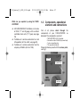
Herzlichen Glückwunsch,
dass Sie sich für das Drehscheiben-Steuergerät
TURN-CONTROL 6915 von FLEISCHMANN
entschieden haben. Das Gerät können Sie für
beliebige,
elektrisch
angetriebene
FLEISCHMANN Drehscheiben (auch Märklin*
7286)
sowohl
in
Gleichstromund
Digitalsystemen
als
auch
in
3-Leiter
Wechselstrom-Anlagen einsetzen, um Ihre
Drehscheibenabgänge
vorzuwählen
und
automatisch anzufahren. TURN-CONTROL lässt
sich auch über DCC- oder LocoNet ferngesteuert
betreiben.
Weder an der Anlage noch an der Drehscheibe
selbst müssen Sie irgendwelche Umbauten
vornehmen.
In dieser Betriebsanleitung beschreiben wir
Schritt für Schritt den Aufbau und die
Einsatzmöglichkeiten mit allem, was Sie zum
Betrieb und Ausbau (z. B. Anschluss weiterer
Drehscheiben) des TURN-CONTROL Geräts auf
Ihrer Anlage benötigen.
Viel Freude mit Ihrem neuen Gerät wünscht
Ihr FLEISCHMANN-Team
* Märklin ist ein eingetragenes Warenzeichen der Gebr. Märklin&Cie GmbH, Göppingen
1
1721_Betra_21_6915_0101.qxd
1
!
27.09.2007
Seite 2
Warn- und
Verwendungshinweise
Verwendungshinweise
Warnhinweise
➜ Lesen Sie im Interesse der Betriebssicherheit
und des ungetrübten Fahrvergnügens diese
Betriebsanleitung komplett durch.
➜ TURN-CONTROL 6915 ist nicht für Kinder
unter drei Jahren geeignet.
➜ Schließen Sie auf keinen Fall Komponenten
oder Gleise direkt an das 230-V-Stromnetz an
(Lebensgefahr)!
➜ Das TURN-CONTROL Gerät und seine
Stromversorgung (z. B. Steckernetzteil 6710)
dürfen unter keinen Umständen mit Wasser in
Berührung kommen! Gehäuse dürfen in
keinem Fall geöffnet werden!
➜ Vor elektrischen Arbeiten an der Modellbahnanlage sollten Sie immer den Netzstecker
ziehen!
➜ Achten Sie beim Betrieb auf lose liegende
Fahrregler-, Netzteil- und Anschlusskabel
(Stolpergefahr).
2
12:14 Uhr
➜ TURN-CONTROL benötigt eine separate
Stromversorgung (Trafo; nicht im Lieferumfang).
➜ Dieses hochwertige Produkt ist für den
Einsatz in trockenen Innenräumen bestimmt.
➜ Um einen einwandfreien Betrieb zu
gewährleisten, sollten Sie die Gleise sowie
die Fahrzeuge regelmäßig säubern.
➜ Zur sicheren Befestigung empfehlen wir
Ihnen, das TURN-CONTROL Gerät auf einer
geeigneten Unterlage (Anlagenplatte o. ä.)
anzuschrauben. 3 Befestigungslöcher auf
der Unterseite der Bodenplatte können
durchgebohrt werden und dienen dann zur
Aufnahme der Befestigungsschrauben.
Alternative: Klebepads. Bitte auch die
Montagehinweise
der
einzelnen
Betriebsanleitungen der anzuschließenden
Geräte beachten!
1721_Betra_21_6915_0101.qxd
27.09.2007
Was können Sie mit dem TURN-CONTROL
steuern?
➜ Alle elektrisch angetriebenen FLEISCHMANN
Gleichstrom-Drehscheiben, Baugrößen H0, TT
und N, mit schaltbaren Abgängen („C-Typen“)
oder ohne (siehe S. 5).
➜ Baugleiche Drehscheiben für MittelleiterWechselstrombetrieb (Art.-Nr. 6652, siehe S.
5).
➜ Drehscheiben der Fa. Märklin (Art.-Nr. 7286)
12:14 Uhr
1.2
Seite 3
Lieferumfang, Bedienelemente und Anschlüsse
Zunächst überprüfen Sie bitte den Lieferumfang
Ihres TURN-CONTROL Gerätes. Er besteht aus:
- TURN-CONTROL 6915 Steuergerät
- Verbindungskabel 39 6865 (zur
Spannungsversorgung)
- 7-poliger Anschlussstecker
- Dieser Betriebsanleitung
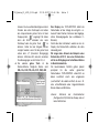
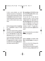
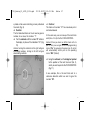
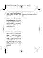
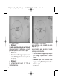
Machen Sie sich nun mit den Bedienelementen
vertraut, siehe Fig. 1.
Display
3 grüne Tasten
roter Dreh-/Tastknopf
Fig. 1
3
1721_Betra_21_6915_0101.qxd
27.09.2007
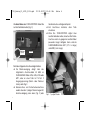
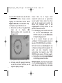
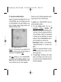
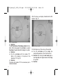
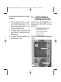
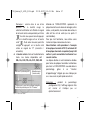
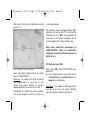
Alle Anschlüsse des TURN-CONTROL finden Sie
auf der Geräterückseite (Fig. 2).
Stecker
(7-pol.)
Fig. 2
Seite 4
Geräterückseite und folgende Kapitel.
➜ Erst Anschlüsse herstellen, dann Trafo
einstecken.
➜ Wenn Sie TURN-CONTROL digital über
LocoNet betreiben wollen, brauchen Sie für den
Anschluss noch ein geeignetes LocoNet-Kabel
passender Länge! Verfügbar hierzu sind die
FLEISCHMANN-Artikel 6887 (2,15 m Länge)
und 6888 (0,6 m Länge).
39 6865
14 ... 18 V
Sie haben folgende Anschlussmöglichkeiten.
➜ Die Stromversorgung erfolgt über das
mitgelieferte Anschlusskabel 39 6865 an
FLEISCHMANN-Trafos 6706, 6735, 6755 oder
6811, oder an einen Trafo mit 14-16,5 V
Ausgangsspannung (Gleich- oder Wechselstrom), siehe Fig. 2.
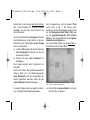
➜ Gleisanschluss und Drehscheibenanschluss
werden über den 7-poligen Stecker hergestellt,
Anschlussbelegung siehe oben (Fig. 2) oder
4
12:14 Uhr
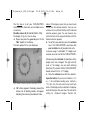
Fig. 3 7-poliger Stecker
1721_Betra_21_6915_0101.qxd
2
27.09.2007
Betrieb
In diesem Kapitel lernen Sie den Anschluss von
TURN-CONTROL an die Drehscheibe und die
Bedienung des Gerätes anhand seiner Menüs
kennen. Schritt für Schritt werden die einzelnen
Funktionen des Geräts erklärt. Das Gerät wurde
so konzipiert, dass für jede elektrisch angetriebene FLEISCHMANN-Drehscheibe die richtige
Bedienung eingerichtet werden kann. Sie
benötigen also mindestens:
1 Drehscheibe 6052 (C), 6152 (C), 6154 (C), 6651
(C), 6652, 6680 (C), 9152 (C), Märklin 7286
(Mittelleiter-Wechselstrombetrieb).
Anmerkung: Das „C“ kennzeichnet Drehscheiben,
deren
Brückenabgänge
wechselseitig
stromführend schaltbar sind. Diese Brücken
können Sie an kleinen „Lücken“ im Brückengleis
erkennen.
2.1 Anlagenanschluss
Prinzipiell
ist
TURN-CONTROL für alle
Modellbahnsysteme verwendbar, 2-Leiter-Systeme
und 3-Leiter-Systeme. Im 2-Leiter-System
12:14 Uhr
Seite 5
unterscheiden wir Analog- (= Gleichstrombetrieb)
und Digitalbetrieb. Obwohl Sie TURN-CONTROL
auch mit den unterschiedlichsten Digitalsystemen
(auch FMZ, Selectrix,etc.) betreiben können, ist die
„Fernsteuerung“ (über Digitalzentralen) nur mit
DCC und LocoNet möglich.
Bei DCC-Digitaltechnik stehen 2 Anschlussvarianten zur Auswahl: Einerseits können alle
Steuersignale über den Gleisanschluss zum
TURN-CONTROL übertragen werden oder Sie
nutzen den LocoNet-Anschluss (= Schienenunabhängig) für diese Aufgabe. Dies setzt speziell
die Kenntnis der Funktionsweise der jeweiligen
Digitalsteuerungszentralen voraus.
Für alle Stromsysteme gleich: Anschlüsse
herstellen.
Stecken Sie zunächst den 7-poligen Klemmstecker in seine Buchse am TURN-CONTROLGerät ein. An den mitgelieferten 7-poligen
Klemmstecker schließen Sie die Anschlusskabel
an (s. Fig. 2).
5
1721_Betra_21_6915_0101.qxd
27.09.2007
Dazu drücken Sie mit einem kleinen
Schraubendreher (s. Fig. 3) von hinten auf die
Feder der entsprechenden Buchse des Steckers
und führen das entsprechende abisolierte und
verdrillte Ende des jeweiligen Kabels in die
Buchse des Steckers ein.
Danach Schraubendreher wieder abnehmen, das
Kabel ist nun fixiert.
A) Bei Anschluss an eine FLEISCHMANN
Drehscheibe für 2-Leiter-Betrieb gilt für den
Anschluss am Klemmstecker:
Die Buchsen 1 und 2 des Steckers schließen Sie
an die von der Gleisanlage kommenden beiden
Kabel „Gleis rechts“ und „Gleis links“ an. An die
Buchsen 3 und 4 werden die Brückengleise der
Drehscheibe (kenntlich an den gelben
Zwillingsanschlusskabeln der Drehscheibe)
angeschlossen. Die Buchse 5 wird mit dem roten
Kabel der Drehscheibe, die Buchse 6 wird mit
dem grauen Kabel der Drehscheibe und die
Buchse 7 wird mit dem gelben Kabel der Drehscheibe verbunden.
6
12:14 Uhr
Seite 6
B) Bei Anschluss an FLEISCHMANN-Drehscheiben 6652 für Mittelleiter-Wechselstrombetrieb gilt:
An die Buchsen 1 und 2 des Steckers schließen
Sie die von der Gleisanlage kommenden beiden
Kabel „Gleis Masse“ (an 1) und „Mittelleiter“ an.
Die Buchse 3 wird mit den beiden gelben
Zwillingskabeln, Buchse 4 mit dem weißen
Kabel des Mittelleiters verbunden. Das rote
Anschlusskabel der Drehscheibe verbinden Sie
mit Buchse 5. Das graue Kabel verbinden Sie mit
Buchse 6 und das gelbe Einzelkabel mit Buchse
7.
Hinweis: Auf der Geräterückseite sind diese
Anschlussbelegungen nochmals beschrieben!
C) Bei Anschluss an Märklin-Drehscheiben 7286
für Mittelleiter-Wechselstrombetrieb gilt:
Schneiden Sie zunächst den „alten“ Stecker an
den Verbindungskabeln der Drehscheibe ab.
An die Buchsen 1 und 2 des 7-poligen
Klemmsteckers Steckers schließen Sie die von
der Gleisanlage kommenden beiden Kabel „Gleis
1721_Betra_21_6915_0101.qxd
27.09.2007
Masse“ (an 1) und „Mittelleiter“ (an 2) an. Die
Buchse 3 wird mit den braunen und orangen
Kabeln, Buchse 4 mit dem gelben Kabel des
Mittelleiters der Drehscheibe verbunden. Das
rote Anschlusskabel der Drehscheibe verbinden
Sie mit Buchse 5. Das blaue Kabel verbinden Sie
mit Buchse 6 und das grüne Kabel mit Buchse 7.
Hinweis: Der Klemmstecker kann nur in der
richtigen Lage in das Gerät eingesteckt werden.
Ein versehentliches „Verdrehen“ der Anschlüsse
beim Einstecken ist daher nicht möglich.
12:14 Uhr
Seite 7
Gleichstromausgang 14-16,5 V des Trafos an. Dies
kann z. B. die schwarze und weiße Schnellklemme
des Wechselstromanschlusses am Trafo 6735 sein.
Den Rundstecker am anderen Ende des Kabels
stecken Sie nun am TURN-CONTROL Gerät in die
runde Buchse mit der Bezeichnung „Power 14 V
ac/dc“ (Fig. 2).
Mögliche FLEISCHMANN-Trafos: 6706, 6710, 6735,
6755, 6811.
Andere Trafos entsprechend anschließen.
Damit ist das TURN-CONTROL Gerät fertig
angeschlossen.
Nun werden wir noch die Stromversorgung für
TURN-CONTROL herstellen. Sie können das
TURN-CONTROL sowohl mit Gleichstrom oder auch
mit Wechselstrom versorgen, wichtig ist nur, dass die
Spannung zwischen 14 V und 16,5 V liegt.
2.2 Anschluss eines Transformators
Das mitgelieferte Verbindungskabel 39 6865
schließen Sie mit den freien Kabelenden an a) den
Wechselstromausgang 14-16,5 V oder b) den
7
1721_Betra_21_6915_0101.qxd
27.09.2007
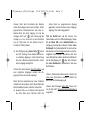
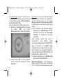
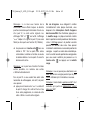
2.3 Bedienung und Menüs
Entfernen Sie die Transportfolie vom Display Ihres
TURN-CONTROL. Wir werden jetzt die real auf der
Anlage vorhandenen Verhältnisse (Drehscheibenmodell,
Brückenposition
und
vorhandene
Gleisabgänge) in das TURN-CONTROL eingeben.
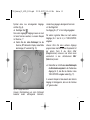
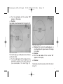
Fig. 4 Display nach dem Einschalten
Hinweis: Dazu ist keine Digitalzentrale oder PC
erforderlich. Alle Einstellarbeiten nehmen Sie
ausschließlich am Gerät selbst vor.
Nach dem ersten Einschalten des TURNCONTROL sollten Sie auf Ihrem Display folgende
Anzeige vorfinden (Fig. 4). Falls nicht, liegt evtl.
eine Störung vor, siehe Anhang „Fehler“.
8
12:14 Uhr
Seite 8
Bitte halten Sie die einzelnen Anpassungsschritte
genau ein, damit Sie schnell zum Erfolg kommen.
Zur Bedienung des TURN-CONTROL haben Sie
folgende Bedienelemente:
➜ Der rote Drehknopf. Er hat 2 Funktionen:
Drehen und Drücken. Drehen des Knopfes
bewirkt
ein
„Weiterspringen“
in
Auswahlmenüs
und
später
ein
„Weiterbewegen“ der Drehscheibenbrücke.
Der rote Drehknopf hat beim Drehen feine
Raststellungen. Pro Raststellung wird ein
neues Menü oder aber ein neuer Abgang
angesteuert.
Drücken
(als
„Taste“)
bewirkt
ein
„Auswählen/Bestätigen“ eines angewählten
Menüpunkts.
Hinweis: Dieses Auswählen/Bestätigen kann
meist gleichwertig auch durch Betätigen einer
bestimmten grünen Taste erfolgen.
➜ Die grünen Tasten. Sie erhalten ihre
Funktionen durch das im Display daneben
stehende Symbol, das je nach Spielsituation
anders beschaffen sein kann.
1721_Betra_21_6915_0101.qxd
27.09.2007
Hinweis: Das Auswählen/Bestätigen wie beim
Drücken des roten Drehknopfs wird neben
der entsprechenden grünen Taste mit dem
Displaysymbol „
“ angezeigt. Sie haben
dann die Wahl, entweder den roten
Drehknopf oder die grüne Taste „
“ zu
drücken. Fehler bei der Eingabe können
korrigiert werden, wenn Sie die grüne Taste
neben dem „C“ (Korrektur/ Rückgängig)
drücken. Minimale Zeit zwischen einzelnen
Druckbewegungen an den Tasten: 0,5 s!
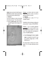
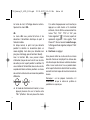
➜ Die oberste grüne Taste ist die
Menüwahltaste. Mögliche Menüs sind:
SEL, Pro, CnF, POL, rEL, CH1, CH2, rES.
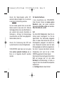
Strich = Brückenhaus
Menü-Auswahl
(grüne Taste)
Symbol für die Drehscheibenbrücke
Position des Brückenhauses: Hier:„9 Uhr“
12:14 Uhr
Seite 9
Das Display des TURN-CONTROL bildet die
Drehscheibe auf der Anlage ab und gibt u. a.
Auskunft über Position, Nummern der Abgänge,
aktive Gleisabgangseite (bei schaltbaren CBrücken).
Damit dies alles funktioniert, werden wir nun im
Display alle Menüschritte vollziehen, die dazu
notwendig sind.
Wir zeigen dies Anhand des Beispiels einer
Drehscheibe 6152 C, also einer Drehscheibe
mit bis zu 48 Abgängen mit schaltbarer Brücke
in Gleichstrombetrieb.
Die beschriebenen Schritte gelten jedoch
prinzipiell
für
alle
vorher
genannten
Drehscheiben. TURN-CONTROL unterstützt sie
dabei zusätzlich durch eine eingebaute
„Lernfunktion“ die selbst ermittelt, ob sie z. B.
eine schnellfahrende oder langsamfahrende
Brücke haben und Ähnliches.
Hinweis:
Während
der
Einstellarbeiten
(Konfiguration CnF) blinkt das Display, dies ist
keine Fehlfunktion.
Fig. 5 Anzeigensymbole
9
1721_Betra_21_6915_0101.qxd
27.09.2007
Der erste Schritt besteht darin, dass Sie dem
TURN-CONTROL mitteilen müssen, wieviele
Abgänge ihre Drehscheibe maximal besitzt.
Mögliche Werte: 48, 24 und 3L (Märklin 7286).
Das Display in Fig. 4 haben Sie vor sich.
➜ Drücken Sie nun bitte auf die grüne Taste,
neben
der
im
Display
„SEL“
(Select=Auswählen) steht. Es erscheint der
Menüpunkt CnF.
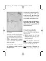
Fig. 6 Abgangszahl (möglicher anderer Wert: 24, 3L)
10
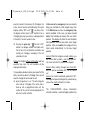
➜ Im Display wird „48“ angezeigt. Kreisförmig
um die Zahl 48 blinken 48 Striche, die die
möglichen Abgänge anzeigen.
12:14 Uhr
Seite 10
Hinweis: Wenn Sie im Display einmal
versehentlich weiter als bis zur gewünschten
Auswahl gedreht haben, drehen Sie einfach
weiter, bis die Auswahl erneut erscheint. Sie
können
den
Drehknopf
auch
in
die
entgegengesetzte Richtung drehen, bis die
gewünschte Auswahl erscheint.
➜ Zur Bestätigung Ihrer Auswahl drücken Sie
nun kurz den roten Drehknopf. TURNCONTROL weiß jetzt, dass Ihre Drehscheibe
48 mögliche Abgänge besitzt.
Da wir in unserem Beispiel von einer
„schaltbaren“ „C“-Brücke ausgehen, müssen wir
dies dem TURN-CONTROL jetzt noch mitteilen.
Nach dem Drücken des roten Knopfes hat sich
im Display die Anzeige der Brücke geändert. Der
rechte
und
linke
Brückenteil
blinken
wechselseitig. Dies bedeutet, dass TURNCONTROL bereits von einer „C“-Brücke ausgeht.
➜ Drücken Sie nun kurz den roten Drehknopf
zur Bestätigung dieser Information.
Wichtiger Hinweis: Wenn Sie eine Drehscheibe
o h n e schaltbare Abgänge (kein „C“) besitzen,
drehen Sie am roten Schaltkopf, bis die beiden
1721_Betra_21_6915_0101.qxd
27.09.2007
Brückenteile in der Anzeige gleichzeitig blinken.
Dies ist die Einstellung für „normale“ Brücken.
Bestätigen Sie dies dann durch Drücken des
roten Drehknopfs.
Als nächstes können Sie die Anzeige der Position
des Brückenhauses mit der Position, in der das
Brückenhaus der Drehscheibe auf der Anlage
steht, synchronisieren.
➜ Im Menü CnF bewegen Sie durch Drehen des
roten Drehknopfs die Brücke auf die real
existierende Position.
➜ Drücken Sie den roten Drehknopf zur
Bestätigung.
Die Anzeige wechselt damit automatisch ins
Menü SEL.
Bereits jetzt können Sie alle Brückenpositionen
„Step by Step“ (d. h. pro Drehbewegung des
roten Drehknopfs wird eine Rastposition der
Brücke angefahren) erreichen, indem Sie den
roten Drehknopf (wiederholt) bewegen.
In unserem Beispiel wollen wir jedoch von der in
Fig. 7 gezeigten Brückenstellung ausgehen.
12:14 Uhr
Seite 11
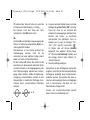
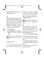
Neu hinzugekommen sind die beiden Pfeile
rechts unten in Fig. 7. Sie können damit
bestimmen, ob der aktive Abgang von der Bühne
auf der Brückenhaus-Seite (linker Pfeil) oder
auf der gegenüberliegenden Seite (rechter
Pfeil) sein soll. Auswahl durch den (unteren) grünen
Knopf neben dem Symbol <-->.
Für unser Beispiel wählen wir die linke Seite (=
Brückenhausseite) als aktive Seite.
<- ->
Fig. 7 Wahl der aktiven Abgangsseite
➜ Drücken Sie den grünen Knopf, bis nur noch
der linke Pfeil zu sehen ist.
11
1721_Betra_21_6915_0101.qxd
27.09.2007
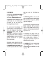
2.4 Abgänge programmieren
Als zweiten Schritt geben Sie nun
3
die real auf Ihrer Anlage vorhanden- 2
4
en Abgänge, z. B. mit 4 Auffahrglei- 1
sen (Nr. 1 bis Nr. 4) in TURN-CONTROL ein.
Prinzipiell können Sie Abgänge auch ohne
angeschlossene Drehscheibe programmieren.
➜ Drücken Sie die grüne (Menü-)Taste „SEL“.
12
12:14 Uhr
Seite 12
Hinweis: Sonst fahren Sie mit dem roten
Drehknopf die gewünschte Position an, wobei
sich das Brückensymbol im Display mitdreht.
Ist die Drehscheibe angeschlossen dreht sich
auch die Brücke mit.
➜ Drücken Sie zur Bestätigung die mittlere grüne
Taste
oder den roten Drehknopf. Im Weiteren nennen wir dies „Bestätigen“.
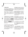
Fig. 8 Position anfahren
Fig. 9 1. Abgang anlegen
Aus „SEL“ wird „Pro“ (=Programmieren) (Fig. 8).
In unserem Beispiel ist der erste Abgang in Position
„9 Uhr“, damit steht die Brücke bereits richtig!
Der linke Teil des Brückensymbols blinkt nun.
Nach Drehen am Drehknopf wird neben dem
Brückenhaussymbol ein kleiner Strich als
1721_Betra_21_6915_0101.qxd
27.09.2007
Symbol eines neu anzulegenden Abgangs
sichtbar (Fig. 9).
➜ Bestätigen Sie!
Den ersten angelegten Abgang müssen wir noch
mit einer Nummer versehen, in unserem Beispiel
mit Nummer „1“.
➜ Drehen Sie den roten Drehknopf, bis die
Nummer „01“ blinkend im Display an der Stelle
der Anzeige „00“ erscheint (Fig. 10).
12:14 Uhr
Seite 13
Linksdrehung dagegen absteigende Nummern.
➜ Bestätigen Sie!
Der Abgang Nr. „01“ ist nun fertig eingegeben.
Wir wollen in gleicher Weise nun noch weitere
Abgänge (Nr. 2 bis Nr. 4) in TURN-CONTROL
eingeben.
Hinweis: Wenn Sie keine weiteren Abgänge
programmieren möchten, können Sie jederzeit mit
der grünen Taste C das Menü „Pro“
(Programmieren) verlassen und kehren dann
automatisch in das „Betriebsmenü SEL“
(Selektieren) zurück.
➜ Drehen Sie nun mit Hilfe des roten Drehknopfs
das Brückenhaussymbol in die Position des
Abgangs (Nr. 2), den Sie als nächstes in das
TURN-CONTROL eingeben wollen (Fig. 11).
In unserem Beispiel ist dies bereits der nächste
Abgang im Uhrzeigersinn, dem wir die Nummer
„02“ geben wollen.
Fig. 10 1. Abgang nummerieren
Hinweis: Rechtsdrehung am roten Drehknopf
bedeutet
dabei
aufsteigende
Nummern,
13
1721_Betra_21_6915_0101.qxd
14
27.09.2007
12:14 Uhr
Seite 14
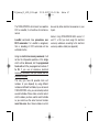
Fig. 11 2. Abgang anlegen
Fig. 12 2. Abgang eingegeben
➜ Bestätigen Sie!
Der linke Teil des Brückensymbols blinkt nun.
Neben dem Brückenhaussymbol wird nach
erneutem Drehen am Drehknopf ein weiterer
kleiner Strich sichtbar.
➜ Bestätigen Sie!
➜ Drehen Sie den roten Drehknopf, bis die
Nummer „02“ blinkend im Display an der
Stelle der Anzeige „00“erscheint (Fig.12).
➜ Bestätigen Sie!
Der Abgang Nr. „02“ ist nun fertig eingegeben.
So wie in Fig. 12 gezeigt, sollte ihr Display nach
diesen Schritten aussehen.
Mit dem dritten Abgang verfahren wir genauso
wie mit dem Zweiten.
➜ Drehen Sie den roten Drehknopf, bis die
Brücke die Position des dritten Abganges
erreicht hat.
➜ Bestätigen Sie! Nach Drehen am Drehknopf
wird wieder ein Abgangsstrich sichtbar.
➜ Bestätigen Sie!
1721_Betra_21_6915_0101.qxd
27.09.2007
12:14 Uhr
Seite 15
➜ Drehen Sie den roten Drehknopf, bis die
Nummer „03“ im Display erscheint.
➜ Bestätigung Sie!
Ihr Display sieht nun so aus (s. Fig. 13):
Fig. 14 4. Abgang anfahren
Fig. 13 3. Abgang eingegeben
Mit dem 4. Abgang (z. B. Drehscheiben-Auffahrt)
verfahren wir genauso wie mit dem Dritten.
➜ Drehen Sie den roten Drehknopf, bis die
Brücke die Position des vierten Abganges
(für unser Beispiel: Position „3 Uhr“) erreicht
hat (Fig. 14).
➜ Bestätigen Sie! Nach Drehen am Drehknopf
wird wieder ein Abgangsstrich sichtbar.
➜ Bestätigen Sie!
➜ Drehen Sie den roten Drehknopf, bis die
Nummer „04“ im Display erscheint.
➜ Bestätigung Sie!
Ihr Display sieht nun aus wie in Fig. 15 gezeigt:
15
1721_Betra_21_6915_0101.qxd
27.09.2007
12:14 Uhr
Seite 16
Das Programmiermenü „Pro“ können wir jetzt
verlassen, dazu drücken Sie bitte auf die grüne
Taste „C“. Das Display zeigt jetzt das Menü
„SEL“ an und Sie können nun ihre angelegten
Abgänge anfahren, wobei Ihnen immer die
jeweilige (programmierte) Abgangsnummer
angezeigt wird.
Alle zum Betrieb nötigen Angaben haben wir
TURN-CONTROL jetzt mitgeteilt, damit
können wir zum Spielbetrieb übergehen.
2.5 Spielbetrieb (Menü SEL)
Fig. 15 4. Abgang eingegeben
Damit haben wir für unser Beispiel alle Abgänge
in TURN-CONTROL eingetragen.
Hinweis: Die Abgangsnummern müssen nicht
fortlaufend im Uhrzeigersinn vergeben werden,
die Benennung können Sie völlig unabhängig von
der Abgangsposition vornehmen.
Unabhängig von der Anzahl der möglichen
Abgänge können Sie die programmierten
Abgänge von 1 bis 99 nummerieren.
16
Mit ihrem TURN-CONTROL können Sie jetzt im
Menü SEL:
➜ Abgänge per Auswahl mit dem roten
Drehknopf anwählen und durch Drücken
anfahren.
Hinweis: Wird die Brückenanzeige verdreht, die
Brücke aber nicht gestartet, geht die Anzeige
nach einer Wartezeit von 10 s wieder in die
ursprüngliche Stellung zurück.
1721_Betra_21_6915_0101.qxd
27.09.2007
Hinweis: Nach dem Einschalten des Gerätes
startet die Anzeige immer in der richtigen, zuletzt
gespeicherten Brückenposition. Bei einer CBrücke blinkt der aktive Abgang. Es sind die
Anzeigen „SEL“ und „
“ aktiv. Ferner zeigt die
Anzeige „<-->“ an, ob es sich um eine C-Brücke
(nur ein Pfeil) oder um eine Brücke ohne CFunktion (2 Pfeile) handelt.
➜ Eine Betätigung der grünen Taste
startet
eine 180°-Drehung. Diese wird bei Brücken ohne schaltbare Abgänge in letzter Drehrichtung
bzw. bei C-Brücken entsprechend dem letzten
aktiven Abgang durchgeführt.
Hinweis: Bei einer Brücke ohne C-Funktion und
zwei möglichen Abgängen werden die Abgangsnummern wechselnd angezeigt.
Wenn Sie ihre Lokomotive bei einer C-Brücke
vielleicht auf der anderen, nicht aktiven Seite der
Brücke abfahren lassen möchten, können Sie
➜ die grüne Taste „<-->“ drücken. Damit wechselt
die aktive Seite einer C-Brücke. Steht der
12:14 Uhr
Seite 17
aktiven Seite ein programmierter Abgang
gegenüber, wird die Nummer dieses Abgangs
angezeigt. Der aktive Abgang blinkt.
Tritt ein Notfall auf und Sie müssen ihre
Drehscheibe sofort zum Stillstand bringen, haben
Sie im Menü SEL einen Nothaltschalter zur
Verfügung. Drücken Sie in diesem Fall den roten
Drehknopf. Die Drehscheibe hält in der nächsten
Rastposition an. Die Anzeige wechselt zur nächstmöglichen Rast-Position. Sie können jetzt eine
neue Soll-Position wählen, die Brücke fährt dann
ab der Bestätigung mit
oder dem Drücken
des roten Drehknopfs automatisch in die neue
Soll-Position.
Hinweis: Während die Brücke dreht, können Sie
keine neue Soll-Position anwählen. Warten Sie
das Ende der Drehbewegung ab.
Hinweis: Bei Drehungen über 360° hinaus wird
nur die über 360° hinausgehende Restbewegung
ausgeführt.
17
1721_Betra_21_6915_0101.qxd
27.09.2007
Hinweis: Bei Regler-Vorgaben größer 180°
arbeitet die Brücke intelligent mit, es wird immer
in der kürzesten Drehrichtung verfahren.
Das Turn-Control speichert intern, ob eine SollPosition erreicht ist oder noch nicht. Wird das
Gerät abgeschaltet, ohne in einer Soll-Position zu
sein, erscheint beim erneuten Einschalten ein
Fehlercode (s. Anhang). Die Brückenanzeige
müssen Sie dann „von Hand" in eine gültige RastPosition drehen (siehe 2.6).
Hinweis: Die Fernsteuerung über DCC oder
LocoNet finden Sie im Abschnitt Digitalbetrieb.
TURN-CONTROL bietet aber noch eine ganze
Reihe weiterer spezieller Funktionen, die wir
Ihnen nun im folgenden Abschnitt vorstellen
möchten.
18
12:14 Uhr
Seite 18
2.6 Spezielle Funktionen
In den Auswahlmenüs des TURN-CONTROL
finden Sie beim Drücken der oberen grünen
Menütaste neben den bereits bekannten
Menüpunkten CnF, SEL und Pro noch die Menüs
POL, CH1, CH2, rEL und rES.
CnF
Das Menü CnF (Configuration) haben Sie am
Anfang bereits kennengelernt, als Sie die
Eigenschaften ihrer Drehscheibe eingegeben
haben. In diesem Menü können Sie auch eine
Brückenposition „korrigieren“, die vielleicht aus
einem Stromausfall resultierte oder Sie haben
Wartungsaufgaben an der Brücke vorgenommen.
Nun stimmt i. allg. dann die Position nach dem
Wiedereinbau nicht mehr mit der in TURNCONTROL gespeicherten Position überein.
Wenn dies der Fall sein sollte, gehen Sie ins Menü
CnF und bewegen dort mit dem roten
Drehknopf die Brückenanzeige im Display so
lange, bis Sie mit der aktuellen Brückenposition
übereinstimmt.
➜ Bestätigen Sie dann diese Position!
1721_Betra_21_6915_0101.qxd
27.09.2007
Die Anzeige wechselt automatisch wieder ins
Menü SEL, d. h. das Anfahren der Abgänge kann
wieder ganz normal fortgesetzt werden.
POL
Die Polarität der Gleise in der Brücke können Sie
an einer beliebigen Position wechseln
(„Polaritätswechsel“).
Dies ist u. a. dann sinnvoll, wenn die Lok nach
einer Drehung um 180 Grad mit der gleichen
Polarität die Brücke verlassen soll, die Sie bei der
Einfahrt hatte. Ohne Polaritätswechsel hätten Sie
sonst einen Kurzschluss mit den Auffahrgleisen!
➜ Wechseln Sie dazu in das Menü POL.
➜ Mit dem roten Drehknopf bewegen Sie die
Brücke an die Position, an der Sie den
Polaritätswechsel geschaltet haben möchten.
Hinweis: Ab dieser Position weisen dann alle im
Uhrzeigersinn folgenden 23 (bzw. 11) möglichen
Abgänge diese Polarität auf.
➜ Bestätigen Sie diese Position!
12:14 Uhr
Seite 19
Das Menü wechselt wieder in das Menü SEL
zurück. Im Betrieb wird jetzt im Display das
Überschreiten der Polwechselposition durch
das Brückenhaus mit dem Symbol „+/-“
angezeigt. Diese zusätzliche Anzeige bleibt
so lange erhalten, bis das Brückenhaus nach
einer halben Umdrehung die Polarität erneut
wechselt.
Hinweis: Der Polwechsel wird wieder aufgehoben, indem im Menü POL bei blinkender
Anzeige „+/–“ die Taste „C“ gedrückt wird.
CH1
Im Menü CH1 (Check 1) können Sie ihre
Drehscheibe testen. TURN-CONTROL „lernt“ auf
diese Weise die Laufeigenschaften ihrer
Drehscheibe kennen und passt daraufhin z. B. die
Laufzeiten zwischen den einzelnen Abgängen an.
➜ Drücken Sie die mittlere grüne Taste
Die Drehscheibe führt jetzt eine Drehung um
360°, also eine ganze Umdrehung aus. Danach
wird eine Umdrehung in die entgegengesetzte
Richtung durchgeführt.
19
1721_Betra_21_6915_0101.qxd
27.09.2007
Tritt während des Tests ein Fehler auf, sehen Sie
im Display eine Fehlermeldung, s. Anhang.
Sie kommen nach dem Ende des Tests
automatisch in das SEL Menü zurück.
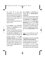
rEL
Im Menü rEL kann die Spannungsversorgung der
Brücke mit Hilfe eines (eingebauten) Relais anund ausgeschaltet werden.
Normalerweise ist die Brücke während der
Drehbewegung stromlos. Dann hat die
Lokomotive bei einer digitalen Anlage jedoch
weder Licht noch evtl. Soundfunktionen.
Mit der Funktion rEL können Sie wählen, ob Sie
eine Brücke mit (dann besteht jedoch die Gefahr
von Kurzschlüssen zu den Abgangsgleisen) oder
ohne Stromversorgung während des Drehvorgangs haben möchten. Würde die Spannungsversorgung aufrechterhalten, würden an den
Gleiskontakten in bestimmten Stellungen Kurzschlüsse durch unterschiedliche Polaritäten
auftreten.
+
–
20
–
+
+
–
+
–
+
–
+
-
u. a.
12:14 Uhr
Seite 20
➜ Aus dem normalen Betrieb heraus mehrmals
Betätigen der grünen Taste „SEL“ (Achtung:
Pause von mind. 0,5 sec zwischen den
einzelnen Druckbewegungen einhalten) bzw.
drücken und halten, es erscheinen
nacheinander (bei gehaltener Taste im
Abstand von 0,5 sec) die Anzeigen "Pro",
„CnF“, „POL“ und „rEL“, ferner blinkt „
“.
Im Display wird die Brücke blinkend
dargestellt. Dies bedeutet „Brücke Power
off“. Wird der rote Drehknopf verdreht, wird
die Anzeige statisch (ohne Blinken) für
„Brücke Power on“.
➜ Diese Einstellung bestätigen!
Kurzschlüsse an den Auffahrgleisen können Sie
umgehen, indem Sie die Schienenverbinder der
Auffahrgleise beidseitig durch Isolierschienenverbinder ersetzen. So erreichen Sie, dass es
zwischen stromversorgter Brücke und Abgängen
nicht zu Kurzschlüssen und damit evtl. zum
Abschalten der Anlage kommt.
Hinweis: Bei 3-Leiter-Drehscheiben besteht
dieses Problem systembedingt nicht.
1721_Betra_21_6915_0101.qxd
27.09.2007
CH2
Im Menü CH2 (Check2) können Sie ihre
LocoNet- oder DCC-Signalverbindung zum
TURN-CONTROL testen.
LocoNet hat beim Datenaustausch immer
Priorität gegenüber DCC.
Das Vorhandensein eines aktiven LocoNets
bzw. DCC-Signals können Sie so prüfen:
➜ Drücken Sie die obere, grüne Taste SEL, bis
das Menü CH2 angezeigt wird.
Das Gerät prüft sofort, und je nach gefundenem
Ergebnis wird als Resultat im Display des TURNCONTROL anstelle der „Abgangsnummer“
folgende Codenummer angezeigt:
0
weder LocoNet noch DCC gefunden,
1
LocoNet gefunden,
2
DCC gefungen,
3
LocoNet und DCC gefunden.
12:14 Uhr
Seite 21
rES
ACHTUNG! Mit dem Menü Reset rES stellen Sie
den Lieferzustand des Gerätes wieder her. Alle
Ihre Eingaben werden gelöscht! Überlegen Sie
gut, welche Einstellungen vorher vorhanden
waren und ob Sie dies alles sicher nachvollziehen
können.
➜ Wenn Sie dennoch ein Reset wünschen,
drücken Sie die grüne Taste
Alle Einstellungen werden auf den Lieferzustand
zurückgesetzt!
Im Folgenden beschreiben wir den Digitalbetrieb
des TURN-CONTROL.
21
1721_Betra_21_6915_0101.qxd
27.09.2007
3. Digitalbetrieb
TURN-CONTROL können Sie digital über LocoNet
kompatible Digitalzentralen (z. B. TWINCENTER 6802) und DCC Systeme betreiben.
Ein Verdrehen der Brücke im Betrieb ist auch über
LocoNet möglich bzw. durch Decodierung der
DCC-Befehle, die über den Eingang des
Schienensignals eingespeist werden.
Die programmierten Brückenabgänge 1-99
entsprechen dabei den Magnetartikeladressen
201 bis 299. Betätigung der roten Taste am
TWIN-CENTER bedeutet dabei, dass das
Brückenende mit Brückenhaus zum gewählten
Abgang gedreht werden soll. Bei der Betätigung
der grünen Taste wird das dem Brückenhaus
gegenüber liegende Ende zum gewählten
Brückenabgang gedreht.
Wenn Sie die rote bzw. grüne Taste am TWINCENTER betätigen und die Brücke steht bereits
in der ausgewählten, richtigen Position, dann
wählen Sie lediglich die aktive Seite der Brücke
22
12:15 Uhr
Seite 22
damit aus, es wird keine 180°-Drehung ausgeführt.
Eine 180°-Drehung der Brücke links oder rechts
herum starten Sie über die Magnetartikel-Adresse
200: rot-rechts (im Uhrzeigersinn), grün-links
(gegen den Uhrzeigersinn).
Die Ansteuerung des TURN-CONTROL von einer
Märklin Control-Unit 6021 wird dadurch
möglich, dass das LocoNet über einen LocoNetAdapter Art. 63820 von Uhlenbrock an die 6021
angeschlossen wird.
Das Empfangen von gültigen Daten über
LocoNet oder über den Schieneneingang (DCC)
wird im Display durch ein Symbol „-> "
angezeigt. Das Symbol bleibt solange aktiv, bis
die gewählte Position erreicht ist.
.
Auf unsinnige DCC- oder LocoNet-Befehle
reagiert TURN-CONTROL nicht, es wird aber das
Fehlersymbol ! und ein Fehlercode (s. Anhang)
angezeigt.
1721_Betra_21_6915_0101.qxd
27.09.2007
Wird über DCC oder LocoNet eine neue SollPosition der Brücke übermittelt, geht die Anzeige
am TURN-CONTROL sofort in die neue SollPosition.
Auf RESET-Pakete über DCC oder LocoNet
reagiert TURN-CONTROL nicht, es läuft normal
weiter.
LocoNet-Befehle haben Vorrang vor DCCBefehlen. Wird ein LocoNet erkannt, wird die
Decodierung
von
DCC-Befehlen
inaktiv
geschaltet.
12:15 Uhr
Seite 23
scheiben über mehrere TURN-CONTROL von
außen ansteuern. Merken Sie sich dabei aber gut
die Abgangsnummern, die sie auf unterschiedlichen Drehscheiben verwendet haben. Die
gleiche Abgangsnummer darf nicht mehrfach
vorkommen und auch nicht für andere
Magnetartikel ihrer Anlage verwendet werden.
Hinweis: Beim TWIN-CENTER 6802, Version 1.0
und 1.1, müssen die Magnetartikeladressen erst
gemäß Tabelle (s. Anhang) zugewiesen werden.
Bei einem Magnetartikelbefehl werden nicht die
48 möglichen Positionen einer Brücke
angesprochen, sondern die programmierten
Abgänge über die programmierten Nummern 1
bis 99. Mit einem falschen MA-Befehl starten Sie
somit keine fehlerhafte Bewegung!
Auf diese Weise (Sie haben ja 99 mögliche
Abgangsnummern zur Verfügung) können Sie bei
Verwendung von unterschiedlichen Nummern auf
verschiedenen Drehscheiben mehrere Dreh23
1721_Betra_21_6915_0101.qxd
27.09.2007
4. Anhang
Im Anhang möchten wir Sie noch auf einige
Besonderheiten des TURN-CONTROL hinweisen.
Fehler werden im Display mit dem Symbol !
und einer Codezahl angezeigt.
Dabei bedeuten:
1 Beim Programmieren ist die gewählte
Abgangsnummer bereits belegt.
2 Das Gerät wurde durch Unterbrechung der
Stromversorgung ausgeschaltet und steht
beim erneuten Einschalten in einer ZwischenPosition.
3 Beim Drehen der Brücke wird der Rastpunkt
zu früh erreicht.
4 Beim Drehen der Brücke wird der Rastpunkt
zu spät erreicht.
5 Bei DCC- oder LocoNet-Betrieb falscher
Abgang gewählt.
6 Kurzschluss
7 Im Betrieb keine Drehscheibe angeschlossen
bzw. Verbindung unterbrochen.
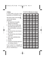
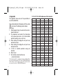
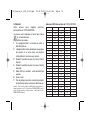
Zur Tabelle: Zur Ansteuerung sind die Adressen 200 bis 299
vorgesehen, Datenformat „D“. Im TWIN-CENTER unter
„Grundeinstellung-> Weicheneinstellung der dig. Adr. v. fiktiven
MA-Decodern“ (s. TWIN-CENTER-Handbuch).
24
12:15 Uhr
Seite 24
TURN-CONTROL -DCC-Adressen der Abgänge
Digit. Adr.
Ausg. 1
Ausg. 2
Ausg. 3
51
201
202
203
204
52
205
206
207
208
53
209
210
211
212
54
213
214
215
216
55
217
218
219
220
56
221
222
223
224
57
225
226
227
228
58
229
230
231
232
59
233
234
235
236
60
237
238
239
240
61
241
242
243
244
62
245
246
247
248
63
249
250
251
252
64
253
254
255
256
65
257
258
259
260
66
261
262
263
264
67
265
266
267
268
68
269
270
271
272
69
273
274
275
276
70
277
278
279
280
71
281
282
283
284
72
285
286
287
288
73
289
290
291
292
74
293
294
295
296
75
297
298
299
50
Ausg. 4
200
1721_Betra_21_6915_0101.qxd
27.09.2007
12:15 Uhr
Seite 25
Dear Railway Modeller,
Page
Thank you for deciding to purchase the TURNCONTROL turntable controller
6915 from
FLEISCHMANN. The controller can be used for
any of the FLEISCHMANN turntables (as well as
Märklin* 7286) either in DC powered or digital
systems and even in 3-rail AC layouts, so that you
can pre-select your desired turntable exit tracks
and automatically rotate the turntable to them.
The TURN-CONTROL can even be operated by
DCC equipment or via LocoNet connections.
26
You won’t need to make any alterations either to
the layout or directly to the turntable itself.
6915 TURN-CONTROL
Turntable Controller
Operating instructions
Contents
GB
1. Safety Warnings and Advice on Use
1.2. Components, operational elements and
connections
2. Operation
2.1 Connection to the Layout
2.2 Connection to a transformer
2.3 Operation and Menu Options
2.4 Using the controller
2.5 Play mode
2.6 Special Functions
3. Digital Operation
4. Appendix
27
29
29
31
32
36
40
42
46
48
In this operational manual, we will describe, step
by step, all you need to know about how to install
and how to use, (i.e. connection to additional
turntables) the TURN-CONTROL controller on
your layout.
The FLEISCHMANN-Team wish you many hours
of enjoyment with your new controller.
* Märklin is a registered trademark of the Company of Gebr. Märklin&Cie GmbH, Göppingen
25
1721_Betra_21_6915_0101.qxd
1
27.09.2007
Safety Warnings
and Advice on Use
!
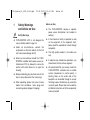
Safety Warnings
➜ TURN-CONTROL 6915 is not designed for
use by children under the age of 3.
➜ Under no circumstances, connect the
components or the track directly to the 240
volt mains power (danger to life)!
➜ Under no circumstances should the TURNCONTROL controller and its power source (i.e.
transformer 6710) be allowed to come into
contact with water! Never try to open the
housing!
➜ Before undertaking any electrical work on the
layout, always disconnect the mains plug!
➜ When operating, please take care of loose
cables from controllers, mains plugs and
connecting cables (danger of tripping).
26
12:15 Uhr
Seite 26
Advice on Use
➜ The TURN-CONTROL requires a separate
power source (transformer: not included in
delivery).
➜ In the interests of safety in operation as well
as the enjoyment of the equipment itself,
please read this operational manual through
completely.
➜ This high quality product is for indoor use
only.
➜ In order to enoy trouble-free operations, you
should clean the rail surfaces regularly.
➜ We recommend that you securely fasten the
TURN-CONTROL controller onto a suitable
surface (baseboard or control panel). 3
locating holes on the under side of the
baseplate can be drilled through to accept
the fixing screws. Alternatively you could also
use sticky pads. Please take care to read the
installation instructions of all the components
to be connected!
1721_Betra_21_6915_0101.qxd
27.09.2007
What can you operate by using the TURNCONTROL?
➜ All FLEISCHMANN DC turntables, in all scales
of 00/HO, TT and N gauge, with or without
switchable track exits ("C" types) (see page
29).
➜ Turntables of a similar construction for 3-rail
AC operation (Art.-No. 6652, see page 29).
➜ Turntables of a similar construction from the
company of Märklin (Art.-No. 7286)
12:15 Uhr
1.2
Seite 27
Components, operational
elements and connections
First of all, please check through the
components of your TURN-CONTROL as
delivered. The components consist of:
- TURN-CONTROL 6915 Controller
- Connection cable 39 6865 (for power feed)
- 7-pole connecting plug
- This operational manual
Please familiarise yourself with the various parts,
see Fig. 1.
Display
3 green keys
red knob
Fig. 1
27
1721_Betra_21_6915_0101.qxd
27.09.2007
All connections of the TURN-CONTROL will be
found on the rear of the equipment (Fig. 2).
plug
(7-pole)
Fig. 2
Seite 28
the rear of the equipment and are decribed in
the following chapter.
➜ Connect up the wires first of all and then plug in
the transformer.
➜ If you wish to use the TURN-CONTROL digitally
or via the LocoNet connection, then you will
also need a suitable length LocoNet cable! The
FLEISCHMANN article 6887 (2.15 m long) and
6888 (0.6 m long) would be best for this use.
39 6865
14 ... 18 V
You now have the following possible connections.
➜ The power feed can be connected up to any of
the FLEISCHMANN transformers 6706, 6735,
6755 or 6811 by using the connecting cable 39
6865 as supplied, or to any transformer which
incorporates a 14-16.5 V continuous voltage
output (DC or AC), see Fig. 2.
➜ Track connections and turntable connections
are made via the 7-pole plug. The location of the
wires can be seen above (Fig. 2) or shown on
28
12:15 Uhr
Fig. 3 7-pole plug
1721_Betra_21_6915_0101.qxd
2
27.09.2007
Operation
In this chapter you will learn all about the
connection of the TURN-CONTROL to the
turntable and the operation of the equipment and
its various menu options. The individual functions
of the equipment will be slowly explained step by
step. The controller has been designed to give the
best possible operation with all types of
FLEISCHMANN electrical turntables. As a
minimum requirement, you will need:
1 turntable, either 6052 (C), 6152 (C), 6154 (C),
6651 (C), 6652, 6680 (C), 9152 (C), Märklin 7286
(3-rail AC operation).
Please Note: The "C" denotes turntables which
are fitted with switchable track ends at each end
of the bridge to turn the power on or off to the
lined up track exit. These can be easily identified
by the tiny isolating rail break at each end of the
turntable rails.
2.1 Connection to the layout
In principle, the TURN-CONTROL is suitable for
12:15 Uhr
Seite 29
all model railway systems, whether, 2-rail or 3rail. We will separate the 2-rail systems into
analog (= standard DC operation) and digital
operation. Although you can use TURNCONTROL with the various digital control
systems, (also FMZ, Selectrix, etc.) "remote
control" (from a central digital controller) is only
possible with DCC and LocoNet.
For DCC digital control, there are two possible
variations for you to select: On one hand, all
control commands can be carried out using track
conection to the TURN-CONTROL, or on the
other, you can use the LocoNet connection
(= independent of rail connection) for this task.
This requires an awareness of the function
methods of the relevant digital controller.
It’s the same for all current systems: simply
make the connections.
First of all, insert the 7-pole plug into its locating
socket on the TURN-CONTROL. Connect up the
wires onto the 7-pole plug (see Fig. 2).
29
1721_Betra_21_6915_0101.qxd
27.09.2007
To make a secure connection, use a small
screwdriver to press down on the spring tension
clamp of the relevant socket (see Fig. 3) and feed
the unisolated and twisted end of the wire into
the relevant plug socket. Remove the screwdriver
and the wire will be retained in place by spring
tension.
A) Here are the plug connections for connecting
up a FLEISCHMANN turntable for 2-rail
operations:
Two wires from the track layout are connected
into sockets 1 and 2 of the plug "right hand track
(1)" and "left hand track". The pair of two
yellow wires (coming from the turntable tracks)
are then connected into sockets 3 and 4. The red
wire from the turntable is connected into socket
5, the grey wire from the turntable is connected
into socket 6 and the remaining yellow wire from
the turntable is connected to socket 7.
30
12:15 Uhr
Seite 30
B) For connecting up a FLEISCHMANN turntable
6652 for 3-rail AC operation (Märklin system),
here are the plug connections:
The two wires from the track layout are
connected into sockets 1 and 2 of the plug
"common track (1)" and "centre rail (2)". The
pair of two yellow wires are then connected to
socket 3, the white wire of the centre rail into
socket 4. The red wire from the turntable is
connected to socket 5. The grey wire is
connected to socket 6 and the yellow wire into
socket 7.
Advice: The wiring instructions are also indicated
on the rear of the equipment!
C) When connecting to the Märklin turntable
7286 for 3-rail AC operation, the wiring is as
follows:
First of all, cut off all of the "old" plugs on the
connecting wires of the turntable.
Connect the wires from the layout into sockets 1
and 2 of the 7-pole plug "common rail (1)" and
1721_Betra_21_6915_0101.qxd
27.09.2007
"centre rail (2)". The brown and orange wires
go into socket 3, the yellow wire of the centre
rail goes into socket 4. The red connecting wire
from the turntable goes into socket 5. The blue
wire goes into socket 6 and the green wire into
socket 7.
Advice: The plug can only be inserted in one way
into the equipment. Thus it is not possible to "mix
up" the connections when inserting the plug.
12:15 Uhr
Seite 31
6735. The small round plug on the other ends of the
wires is then inserted into the socket on the TURNCONTROL marked "Power 14 V ac/dc" (Fig. 2).
Possible FLEISCHMANN transformers: 6706, 6710,
6735, 6755, 6811.
Other transformers are connected up in a similar
manner.
Now the TURN-CONTROL is connected up and
ready for use.
Now we will create the power feed for the TURNCONTROL. You can feed the TURN-CONTROL
either with DC or AC power so long as the power
is continuous, between 14 volts and 16.5 volts.
2.2 Connection to a transformer
Using the connecting cable supplied, 39 6865,
connect the free ends of the wires onto - a) the
continuous AC output 14-16.5 V or - b) the
continuous DC output 14-16.5 V of the transformer.
This could be, for example, the black and white clips
of the AC output on a FLEISCHMANN transformer
31
1721_Betra_21_6915_0101.qxd
27.09.2007
2.3 Operation and Menu Options
Remove the protective packaging foil from your
TURN-CONTROL. We are now going to put into
the TURN-CONTROL the actual situation of your
layout (turntable model, bridge position and
locations of the track exits).
Fig. 4 Display after switch-on
Advice: It is not necessary to use a digital central
controller or PC to do this. All of the settings are
carried out on the equipment itself.
After first switching on your TURN-CONTROL
you should see the following indication in the
display (Fig. 4). If not, then there may be a fault,
so you can look it up in the "error" appendix.
32
12:15 Uhr
Seite 32
Please carry out the following procedure exactly,
step by step, so that it is done correctly.
To operate your TURN-CONTROL there are
certain operational controls:
➜ The red rotating knob. This has 2
operational functions: Rotation and
Depression. Rotating the knob brings up the
"next step" in the menu selection and later to
"set the turntable in motion". As the red knob
is rotated, there are detectable, fine control
setting of "notches". Each notch will select a
new menu option or a new track exit.
Depressing the knob (as a "key") denotes a
"selection/confirmation" of a chosen menu
option.
Advice: This "selection/confirmation" can also
be similarly carried out by using one of the
relevant green keys.
➜ The green keys. According to the symbol
shown in the display next to each key, they
are used to carry out the required functions of
the relevant operation.
1721_Betra_21_6915_0101.qxd
27.09.2007
Advice: The selection/confirmation by
depressing the red knob will be indicated by a
symbol "
" in the display next to the
corresponding green key. You then have the
choice either to press the red knob or the
green key "
". If you have made a mistake
in entering the instruction, then this can be
cancelled by pressing the green key next to
the "C" (correction/cancel). The minimum
time between two depressions should be 0.5 s!
➜ The uppermost green key is the menu
selection key. Possible menu options are:
SEL, Pro, CnF, POL, rEL, CH1, CH2, rES.
Marker = bridge hut
Choice of menu
(green key)
Symbol for the turntable bridge
Position of the bridge hut; here:“9 o’clock“
Fig. 5 Display symbols
12:15 Uhr
Seite 33
The display of the TURN-CONTROL shows the
turntable on the layout and gives information on
its current position, numbers of the track exits,
the active exit side of the turntable (on switchable
C-bridges).
So that everything works correctly, we will now
call up in the display all of the menu options or
steps which you will find necessary.
We will now show you how to set up your
TURN-CONTROL, step by step, using as an
example a turntable 6152 C, which is a
turntable with up to 48 track exits with a
switchable bridge, in DC operation.
However, each of the steps described will also
apply in principle for all of the turntables
previously listed. TURN-CONTROL has the
additional facility of an inbuilt "learning function"
where it finds out for itself whether your turntable
rotates slowly or quickly, and some other
characteristics.
Advice: During the setting procedure,
(configuration CnF) the display will blink, so
this is not a malfunction.
33
1721_Betra_21_6915_0101.qxd
27.09.2007
The first step is to let your TURN-CONTROL
know how many track exits your turntable has as
a maximum.
Possible values: 48, 24 and 3L (Märklin 7286).
The display in Fig. 4 is now on show.
➜ Please now press the green key next to the
"SEL" (select) in the display.
The menu option CnF is now displayed.
12:15 Uhr
Seite 34
Advice: If the display shows that you have turned
further than the desired selection, then you can
continue to turn a little bit further until the desired
selection appears again. You can however, also
rotate the knob in the opposite direction until the
desired selection appears.
➜ To confirm your selection, press the red knob
once. The TURN-CONTROL now knows that
your turntable has 48 possible track exits.
As we are using a "switchable" "C" bridge in our
example, we must now tell the TURN-CONTROL.
After pressing the red knob, the indications in the
display have now changed. The right and left
ends of the bridge are now both blinking
alternately. This means that the TURN-CONTROL
already knows that it is a "C" bridge.
➜ Press the red knob to confirm this selection.
Fig. 6 Number of exit tracks (possible other values: 24, 3L)
➜ "48" will now appear in the display. Around the
number 48, 48 blinking markers will appear,
indicating the number of possible exit tracks.
34
Important advice: If you have a turntable w i t h
o u t the switchable isolating ends, (without a
"C"), then turn the red control knob until both
ends of the bridge section indicated in the display
are both blinking at the same time. This will be the
setting for "standard" bridges. Confirm this
1721_Betra_21_6915_0101.qxd
27.09.2007
selection by pressing the red knob.
The next step is to synchronise the position of the
bridge hut in the display with the actual current
position of the bridge hut on the turntable on the
layout.
➜ In menu option CnF, rotate the red control
knob until the bridge is in the current
position.
➜ Press the red knob to confirm this selection.
The display will now automatically switch to the
SEL menu option.
Now you will be able to access all bridge
positions "step by step" (with each rotation of the
red knob, the bridge will turn to the next available
track exit, or rest setting) in accordance with the
way you have turned the red knob.
In our example, however, we will start from the
bridge position shown in Fig. 7.
A new feature that you will now be aware of are
the two arrows on the bottom right of Fig. 7. You
can now determine which of the active track ends
12:15 Uhr
Seite 35
should be live – either the bridge hut side (left
arrow) or on the opposite side (right arrow).
The selection is made using the green key
beneath the symbol <-->.
For the purpose of our example, we will select the
left side (= bridge hut side as the live side).
<- >
Fig. 7 Selecting the live track end side
➜ Press the green key until only the left arrow is
visible.
35
1721_Betra_21_6915_0101.qxd
27.09.2007
2.4 Exit track Programming
As the second step, you must now put
into the TURN-CONTROL the actual 2 3
4
track exit positions which you have 1
on your layout, for example, with
4 exit tracks (Nos. 1 to 4).
In principle, you can program exits without even
having the turntable connected.
➜ Press the green (menu) key “SEL“.
12:15 Uhr
Seite 36
In our example, the first track exit is in the position
at "9 o’clock", with the bridge in the correct
position!
Advice: If not, turn the red knob to the desired
position so that the bridge symbol in the display
turns with it.
➜ To confirm the selection, press the central green
key
or the red knob. From now on, in this
manual we will be calling that “confirm“.
The left hand section of the bridge symbol will
now blink and a tiny strip next to the bridge hut
Fig. 8 Reach position
The indication will change from "SEL" to "Pro"
(Programming, Fig. 8).
36
Fig. 9 1. Create 1st exit
1721_Betra_21_6915_0101.qxd
27.09.2007
symbol will be seen indicating a newly allocated
track exit (Fig. 9).
➜ Confirm!
The first allocated track exit must now be given a
number, in our case, the number "1".
➜ Turn the red knob until the number "01" blinks in
the display in place of the indication "00" (Fig.
10).
Advice: turning the red knob to the right will give
ascending numbers, turning to the left will give
descending numbers.
12:15 Uhr
Seite 37
➜ Confirm!
The track exit number "01" has now been put in
and remembered.
In the same way, we can now put the next track
exits (Nos. 2 to 4) into the TURN-CONTROL.
Advice: Once you have no further track exits to
put in, then you can get out of the programming
menu "Pro" by pressing the green key C, which
will automatically return you to the operating
menu "SEL" (Select).
➜ Using the red knob, turn the bridge hut symbol
to the position of the next track exit (No. 2),
which you wish to put into the TURN-CONTROL
(Fig. 11).
In our example, this is the next track exit in a
clockwise direction which we wish to give the
number "02".
Fig. 10 Give the first exit a number
37
1721_Betra_21_6915_0101.qxd
27.09.2007
12:15 Uhr
Seite 38
After this step, your display should look like that
shown in Fig. 12.
Fig. 11 Create 2nd exit
➜ Confirm!
The left hand side of the bridge symbol will now
blink. After turning again the red knob, a second
tiny strip will appear beside the bridge hut symbol.
➜ Confirm!
➜ Turn the red knob until the number "02"
blinks in the display in the place of the
indication "00" (Fig.12).
➜ Confirm!
The track exit number "02" has now been put in
and remembered.
38
Fig. 12 2. Put in 2nd exit
The third step is just the same as the second.
➜ Turn the red knob until the bridge has
reached the position of the third track exit.
➜ Confirm! After turning the red knob again, a
new tiny strip will appear beside the bridge
hut symbol.
➜ Confirm!
1721_Betra_21_6915_0101.qxd
27.09.2007
12:15 Uhr
Seite 39
➜ Turn the red knob until the number "03"
appears in the display.
➜ Confirm!
Your display should now look like this (see Fig. 13):
Fig. 14 Go to the 4th exit
Fig. 13 Put in 3rd exit
The fourth step (e.g. creating the access track) is
just like the third.
➜ Turn the red knob until the bridge hut has
reached the position of the fourth track exit
(as in our example, at "3 o’ clock") (Fig. 14).
➜ Confirm! After turning the red knob again, a
new tiny strip will appear beside the bridge
hut symbol.
➜ Confirm!
➜ Turn the red knob until the number "04"
appears in the display.
➜ Confirm!
Your display should now look just like that shown
in Fig. 15:
39
1721_Betra_21_6915_0101.qxd
27.09.2007
12:15 Uhr
Seite 40
We can now leave the programming menu "Pro",
so please press the green "C" key. The display
will now show the menu "SEL" and you can now
use the track exits which will always be shown
with the individual (programmed) exit numbers.
We have now told the TURN-CONTROL all it
needs to know about the tasks it has to
perform, so we can now proceed to the next
section on how to use it.
2.5 Using the Controller (Menu SEL)
Fig. 15 Put in 4th exit
You have now successfully entered the positions
of all your track exits into the TURN-CONTROL.
Advice: The exit numbers do not necessarily have
to be in a clockwise direction. The numbering
system can be completely independent of the
position of the track exit.
Independent of the number of possible track
exits, you can assign the numbers 1 through 99 to
your programmed exits.
40
With your TURN-CONTROL in the SEL menu
setting, you can now:
➜ Select the desired exit track using the red
rotating knob and then by pressing it, turn the
bridge to the selected exit.
Advice: If the bridge display rotates, but the
turntable is not started, the display will return to
the original start position within 10 seconds.
Advice: When switching on the equipment, the
display will always start up in the last correct
1721_Betra_21_6915_0101.qxd
27.09.2007
position stored in the memory. On C-bridges, the
active, live exit section will be blinking. The active
displays will be "SEL" and "
". As well as that,
the display will also show "<-->" whether it has a
C-bridge type (only one arrow) or a bridge without
C-function (2 arrows) under control.
➜ Pressing the green key "
"will start a 180°
rotation. For bridges without switchable exits,
this will be in the last direction of rotation, and
similarly for C-bridges, according to the last
selected exit track.
Advice: For bridges without a C-function, and two
possible track exits, the exit numbers will be
displayed alternately.
If you perhaps decide to drive your loco off of the
other, non-active side of a C-bridge, then you will
need to change the active side to suit.
➜ press the green key "<-->". This will change the
active side of a C-bridge. If the active side is
lined up with a programmed track exit, the
number of this exit will also be displayed. The
active exit section will blink.
12:15 Uhr
Seite 41
In the case of an emergency when you need to
bring your turntable to a halt straight away, then
in the SEL menu you have an emergency stop
button available. In this case, just press the red
knob. The turntable will stop at the next notch
position. The display will show the next available
notch position. You can now select a new target
position. After you confirm, the bridge will now
travel round automatically to the new target
position.
Advice: Whilst the bridge is actually rotating, you
will not be able to select a new target position.
You must wait until the rotation has stopped.
Advice: When rotating through more than 360°
only the postion exceeding 360° will be carried
out.
Advice: For control commands greater that 180°,
the bridge will operate intelligently, and will always
choose the shortest direction to rotate.
The TURN-CONTROL stores information
internally whether a selected target position has
41
1721_Betra_21_6915_0101.qxd
27.09.2007
been reached or not. If the equipment is switched
off and it is not in the correct selected position,
then on being switched on again an error code
will be displayed (see appendix). The bridge
symbol in the display must then be rotated "by
hand" into the relevant position. (see 2.6).
Advice: The remote control via DCC or LocoNet
can be found in the digital operation section.
TURN-CONTROL is also capable of performing
additional special functions which we have set
out for you in the following section.
42
12:15 Uhr
Seite 42
2.6 Special Functions
Within the menu options of the TURN-CONTROL ,
by pressing the upper green menu key,
alongside the already mentioned menu options
CnF, SEL and Pro you will also find the menu
options POL, CH1, CH2, rEL and rES.
CnF
You have already discovered the CnF menu
(Configuration) at the beginning, as you set up
the capabilities of your turntable. In this menu,
you can also "correct" the bridge position which
may have been altered by the current being cut
off or by you carrying out some maintenance so
the actual position no longer corresponds to that
stored by the TURN-CONTROL.
If this should be the case, then go into the CnF
menu and then rotate the red knob until the
bridge position indicated in the display actually
corresponds to the current position.
➜ Confirm this position.
.
The display will automatically switch to the SEL
1721_Betra_21_6915_0101.qxd
27.09.2007
menu, in other words, the exit tracks can now be
accessed in the normal way.
POL
You can change the polarity of the tracks of the
bridge in any desired position ("Polarity change").
This is handy to have so that, if after rotating
through 180 degrees, the loco moves off of the
bridge with the same polarity as it had when
entering. Without changing the polarity, there
would be a short circuit with the exit tracks!
➜ Go into the POL menu.
➜ using the red knob, rotate the bridge into the
position in which you wish to change the
polarity.
Advice: Clockwise from this position, then the
next 23 (11) possible track exits will take this
polarity.
➜ Confirm this position!
The menu will now change back to the SEL
menu. As an indication of this change of polarity,
12:15 Uhr
Seite 43
the symbol "+/-" will be shown when the bridge
hut is moved over that position. This additional
indication will remain in the display until the
bridge hut has completed a complete half turn,
changing the polarity anew.
Advice: To switch off the changing of polarity, go
to menu POL and, while “+/–” is blinking, press
key “C”.
CH1
In the menu CH1 (Check 1) you can test your
turntable. This will allow the TURN-CONTROL to
"learn" the running characteristics of your
turntable and fits in with it. For example, the time
taken to rotate between each exit.
➜ Press the central green key or the red knob.
The turntable will now rotate through a complete
360°. Then it will rotate again in the opposite
direction.
If an error should be discovered during the test,
then a relevant error code will be dispayed (see
appendix).
At the end of the test, you will automatically be
returned to the SEL menu.
43
1721_Betra_21_6915_0101.qxd
27.09.2007
rEL
In the menu option rEL, the bridge power can be
turned on or off using a small relay.
Normally, whilst the bridge section is rotating, the
rails have no power. This means that the
locomotive on a digital layout will not have its
lights on, nor if applicable, any sound function.
Using the rEL function, you can choose whether
to have the power to the rails on or off whilst it is
rotating (if turned on, then there is the danger of a
short circuit with the exit tracks). In certain
positions, short circuits may occur when passing
track exits with a different polarity setting.
+
-
+
+
-
+
-
+
-
+
-
and other
➜ To access the rEL function out of the normal
operational mode, press the green "SEL" key
several times (attention: pause for at least 0.5
seconds in between each pressing of the key)
or similarly, press the key and hold it down,
when the sequence of menu options will be
displayed one after the other (at 0.5 second
44
12:15 Uhr
Seite 44
intervals as long as you keep the key pressed)
"Pro", "CnF", "POL" and "rEL", when "
"
will blink in the dispay. In the display, the
bridge will be shown blinking. This means
"bridge power off". If the red knob is turned,
then the display will be static (without
blinking) for "bridge power on".
➜ Confirm this setting!
Short circuits on the entry track can be prevented
by inserting isolating rail joiners on both rails. This
will prevent short circuits between the powered
bridge and exit tracks, and thus a possible
switching off of the layout.
Advice: This problem does not occur in 3-rail
system operation.
CH2
In Menü CH2 (Check2) you can test your
LocoNet or DCC signal connection.
For exchange of data, LocoNet will always take
precedence over DCC.
1721_Betra_21_6915_0101.qxd
27.09.2007
You can check whether you have an active
LocoNet, or similarly a DCC signal:
➜ Press the upper, green key SEL, until the
menu CH2 is displayed.
The equipment will check immediately and
according to its findings, will indicate the result in
the display (where normally the exit numbers are
shown) of the TURN-CONTROL by the following
code numbers:
0
neither LocoNet nor DCC found,
1
LocoNet found,
2
DCC found,
3
LocoNet and DCC found.
12:15 Uhr
Seite 45
➜ If you wish to carry out a reset, press the
green key.
All settings will be set back to those at time of
delivery!
In the following section, we will now describe the
digital operation of the TURN-CONTROL.
rES
ATTENTION! With the Reset menu rES you will
set the equipment back to its settings as
delivered. All of your input data will be erased!
Please consider carefully which settings you have
created previously and whether you really wish to
remove them.
45
1721_Betra_21_6915_0101.qxd
27.09.2007
3. Digital operation
You can operate the TURN-CONTROL with any
LocoNet compatible digital central controller
(i.e. TWIN-CENTER 6802) and DCC Systems.
Rotating the bridge is also possible via the
LocoNet or similarly by decoding the DCC
commands which are received from the rail
signals.
The programmed track exits, 1-99, correspond to
the electrical article adresses 201 to 299.
Pressing the red key on the TWIN-CENTER
means that the bridge hut end of the turntable will
rotate to the selected track exit. By pressing the
green key on the TWIN-CENTER, the end
opposite the hut end will be turned around to the
selected track exit.
If you press the red, or green, key on the TWINCENTER and the bridge is already in the
correct, desired position, you will only be
selecting the active side of the bridge, then it
will not rotate through 180°.
46
12:15 Uhr
Seite 46
A 180° rotation of the bridge, left or right can be
started with the electrical accessory address 200:
red-right (clockwise), green-left (anti-clockwise).
Using the TURN-CONTROL in conjunction with a
Märklin Control-Unit 6021 is possible by
connecting the LocoNet via a LocoNet-Adapter
Art. 63820 from Uhlenbrock which is then
connected to the 6021.
Receiving valid data via the LocoNet or from the
track feed (DCC) will be indicated in the display
by the symbol "->.". The symbol remains active
until the selected position has been reached.
The TURN-CONTROL will not react to invalid
DCC or LocoNet commands, but will show the
error symbol " ! " together with an error code
(see appendix).
If a new selected position of the bridge is
transmitted via DCC or the LocoNet, then the
TURN-CONTROL indicator will also immediately
turn to the new selected position.
1721_Betra_21_6915_0101.qxd
27.09.2007
The TURN-CONTROL will not react to a reset via
DCC or LocoNet, it will continue to function as
normal.
LocoNet commands have precedence over
DCC commands. If a LocoNet is recognised,
then a decoding of DCC commands will be
switched inactive.
12:15 Uhr
Seite 47
be used by other electrical accessories on your
layout.
Advice: Using TWIN-CENTER 6802, version 1.0
and 1.1, at first you must assign the electrical
accessory addresses according to the electrical
accessory address table (see Appendix).
Using an electrical accessory command, it will
not be the 48 possible positions of the bridge
which will be addressed, but the programmed
track exits with the pre-progammed numbers 1
to 99. If you use an erroneous electrical
accessory command, then you cannot start an
erroneous rotation!
This way (you have 99 possible track exit
numbers at your disposal) by using different
numbers on different turntables, by use of several
TURN-CONTROL units, you can remotely control
several turntables. Please make a careful note of
which numbers you have used for each turntable
as you cannot use the same track exit number
more than once. Also, these numbers must not
47
1721_Betra_21_6915_0101.qxd
27.09.2007
4. Appendix
This appendix shows some of the specialities of
the TURN-CONTROL.
Errors will be indicated in the display with this symbol
" ! " and one of the following code numbers.
Indicating:
1 When programming, the selected track exit is
already allocated.
2 The equipment was tuned off by interruption
of the power feed and is in the intermediate
position awaiting a new switch on.
3 When rotating the bridge the rest point was
reached too soon.
4 When rotating the bridge the rest point was
reached too late.
5 In DCC or LocoNet operation wrong exit
selected.
6 Short Circuit
7 No turntable connected, likewise
– connection broken.
To the table beneath: For controlling, the adresses 200 to 299 are
to be used, the data format is “DC“. Refer to TWIN-CENTER under
„Basic settings-> switch settings of dig. addr. of virtual electrical
accessory decoders“ (see TWIN-CENTER-manual).
48
12:15 Uhr
Seite 48
TURN-CONTROL-DCC-addresses of the track exits.
Digit. Addr.
exit 1
exit 2
exit 3
51
201
202
203
204
52
205
206
207
208
53
209
210
211
212
54
213
214
215
216
55
217
218
219
220
56
221
222
223
224
57
225
226
227
228
58
229
230
231
232
59
233
234
235
236
60
237
238
239
240
61
241
242
243
244
62
245
246
247
248
63
249
250
251
252
64
253
254
255
256
65
257
258
259
260
66
261
262
263
264
67
265
266
267
268
68
269
270
271
272
69
273
274
275
276
70
277
278
279
280
71
281
282
283
284
72
285
286
287
288
73
289
290
291
292
74
293
294
295
296
75
297
298
299
50
exit 4
200
1721_Betra_21_6915_0101.qxd
27.09.2007
12:15 Uhr
Seite 49
Félicitations !
6915 TURN-CONTROL
Commande de plaque
tournante
Instructions de service
F
Sommaire
Avertissements et consignes
d'utilisation
1.2. Livraison, éléments de commande et
connexions
2. Fonctionnement
2.1 Connexion au réseau
2.2 Connexion d'un transformateur
2.3 Commande et menus
2.4 Paramétrer les sorties
2.5 Mode jeu
2.6 Fonctions spéciales
3. Mode digital
4. Annexe
Page
1.
50
51
53
53
55
56
60
64
66
70
72
Nous vous remercions d'avoir fait l'acquisition de
la commande de plaque tournante TURNCONTROL 6915 de FLEISCHMANN. Compatible
avec
toutes
les
plaques
tournantes
FLEISCHMANN (y compris Märklin* 7286) des
systèmes à courant continu et digitaux tout
comme des systèmes à courant alternatif à 3
conducteurs, cet appareil vous permet de
présélectionner les accès de votre plaque
tournante, et aux locomotives de les emprunter
automatiquement. TURN-CONTROL fonctionne
aussi via les télécommandes DCC ou LocoNet.
Aucune modification n'est nécessaire ni sur votre
réseau ni sur votre plaque tournante.
Ces instructions de service présentent pas à pas
l'installation et les possibilités d'utilisation de la
commande TURN-CONTROL et décrit tout ce
dont vous avez besoin pour le fonctionnement et
l'extension (par ex. via la connexion d'autres
plaques tournantes) de votre réseau.
Nous espérons que cette nouvelle commande
vous donnera beaucoup de satisfactions,
Votre équipe FLEISCHMANN
* Märklin est une marque déposée de la société Gebr. Märklin&Cie GmbH, Göppingen
49
1721_Betra_21_6915_0101.qxd
1
27.09.2007
Avertissements et
consignes d'utilisation
!
Avertissements
➜ Le TURN-CONTROL 6915 n'est pas adapté
aux enfants de moins de trois ans.
➜ Ne connectez en aucun cas les composants
ou rails directement au secteur 230 V (danger
de mort) !
➜ Le TURN-CONTROL et son alimentation
électrique (par ex. adaptateur secteur 6710)
ne peuvent entrer en contact avec l'eau !
N'ouvrir en aucun cas leur boîtier !
➜ Avant toute intervention sur le circuit
électrique de votre réseau, veillez à toujours
débrancher la fiche de la prise secteur !
➜ Pendant l'utilisation de votre réseau, veillez
aux fils du régleur, de l'adaptateur secteur et
aux câbles de connexion (risque de
trébuchement).
50
12:15 Uhr
Seite 50
Consignes d'utilisation
➜ Le TURN-CONTROL fonctionne sur une
alimentation électrique séparée (transfo, non
fourni).
➜ Afin de garantir la sécurité de fonctionnement
de l'appareil et un plaisir de jouer intact,
veuillez lire cette notice dans son intégralité.
➜ Ce produit de haute qualité est destiné à une
utilisation dans une pièce sèche.
➜ Pour
garantir
un
fonctionnement
irréprochable, n'oubliez pas de nettoyer
régulièrement les rails et les véhicules.
➜ Pour qu'il soit bien fixé, nous vous
recommandons de visser le TURNCONTROL sur un support approprié
(panneau du réseau etc.). Le dessous de
l'appareil peut être percé de trois orifices
permettant de passer les vis de fixation.
Alternative : pastilles autocollantes. Veuillez
observer les consignes de montage figurant
dans les notices des composants à
connecter !
1721_Betra_21_6915_0101.qxd
27.09.2007
12:15 Uhr
Seite 51
Que pouvez-vous commander avec le TURNCONTROL ?
1.2
Livraison, éléments de
commande et connexions
➜ Toutes les plaques tournantes à courant
continu FLEISCHMANN, échelles H0, TT et N,
avec sorties commutables ("types C") ou sans
sorties commutables (voir p. 53).
➜ Les plaques tournantes équivalentes pour
courant alternatif à conducteur central (réf.
6652, voir p. 53).
➜ Les plaques tournantes équivalentes de la
marque Märklin (réf. 7286).
Veuillez d'abord vérifier l'intégralité de la
livraison de votre TURN-CONTROL. L'emballage
doit contenir :
- Commande TURN-CONTROL 6915
- Câble de connexion 39 6865
(pour l'alimentation électrique)
- Connecteur à 7 pôles
- La présente notice
Identifiez les différents éléments de commande,
voir fig. 1.
L'écran
3 touches vertes
La molette rouge
Fig. 1
51
1721_Betra_21_6915_0101.qxd
27.09.2007
Toutes les connexions du TURN-CONTROL se
situent à l'arrière de l'appareil (fig. 2).
Connecteur
à 7 pôles
Fig. 2
Seite 52
l'appareil et dans les chapitres suivants.
➜ Connectez d'abord les fils avant de brancher le
transfo.
➜ Si vous souhaitez commander le TURNCONTROL par voie digitale via LocoNet, vous
avez besoin d'un câble LocoNet de longueur
adaptée pour la connexion ! Pour cela, vous avez
le choix entre les articles FLEISCHMANN 6887
(longueur : 2,15 m) et 6888 (longueur : 0,6 m).
39 6865
14 ... 18 V
Elles vous offrent les possibilités de
raccordement suivantes :
➜ L'alimentation électrique doit être assurée via le
câble de connexion 39 6865 fourni et les
transfos FLEISCHMANN 6706, 6735, 6755 ou
6811 ou avec un transfo délivrant 14-16,5 V
(courant continu ou alternatif), voir fig. 2.
➜ Raccordement au rail et à plaque tournante via
le connecteur à 7 pôles, affectation des
polarités voir ci-dessus (fig. 2) ou à l'arrière de
52
12:15 Uhr
Fig. 3 Connecteur à 7 pôles
1721_Betra_21_6915_0101.qxd
2
27.09.2007
Fonctionnement
Ce chapitre décrit la connexion du TURNCONTROL à la plaque tournante et la commande
de l'appareil à l'aide de ses menus. Il explique
pas à pas les différentes fonctions de la
commande. Cet appareil a été conçu pour
permettre la configuration adéquate de toutes les
plaques tournantes FLEISCHMANN. Pour cela, il
vous faut donc au minimum :
1 plaque tournante 6052 (C), 6152 (C), 6154 (C),
6651 (C), 6652, 6680 (C), 9152 (C), ou Märklin
7286 (courant alternatif à conducteur central).
Remarque : le "C" désigne les plaques tournantes
dont les sorties du pont sont conductrices de
courant et commutables alternativement. Vous
les reconnaissez aux petits "jours" dans les rails
du pont.
2.1 Connexion au réseau
En principe, le TURN-CONTROL est compatible
avec tous les réseaux (systèmes à 2 et 3
conducteurs). Dans le système à 2 conducteurs,
12:15 Uhr
Seite 53
nous faisons la distinction entre la version
analogique (= courant continu) et la version
digitale. Même si le TURN-CONTROL est
compatible avec différents systèmes digitaux (y
compris FMZ, Selectrix etc.), la "télécommande"
(via les centrales digitales) n'est possible qu'avec
les technologies DCC et LocoNet.
Le technologie digitale DCC permet de réaliser 2
connexions différentes : tous les signaux de
commande peuvent être transmis vers le TURNCONTROL via le raccordement du rail ou via
l'interface LocoNet (= indépendante des voies).
Vous devez alors connaître le mode de
fonctionnement de la centrale digitale en
question.
Vaut pour tous les systèmes de courant :
vous devez réaliser les connexions.
Branchez d'abord le connecteur à 7 pôles dans
sa prise du TURN-CONTROL. Raccordez les
câbles de connexion au connecteur à 7 pôles
fourni (voir fig. 2).
53
1721_Betra_21_6915_0101.qxd
27.09.2007
Pour cela, à l'aide d'un petit tournevis (voir fig. 3)
appuyez depuis l'arrière sur le ressort de la borne
correspondante du connecteur et introduisez
l'extrémité dénudée et tordu du fil dans la borne
du connecteur.
Ensuite, retirez le tournevis. Le fil est à présent
immobilisé.
A) Pour brancher une plaque tournante
FLEISCHMANN à 2 conducteurs, la connexion
se réalise sur le connecteur à bornes :
Connectez les bornes 1 et 2 du connecteur aux
deux fils venant du réseau „rail droit“ et „rail
gauche“. Connectez les bornes 3 et 4 4 aux rails
du pont de la plaque tournante (reconnaissables
aux fils de branchement jumeaux de couleur
jaune de la plaque tournante). Raccordez la
borne 5 au fil rouge de la plaque tournante, la
borne 6 au fil gris de la plaque tournante et la
borne 7 au fil jaune de la plaque tournante.
B) Pour brancher une plaque tournante
FLEISCHMANN 6652 pour courant alternatif à
conducteur central :
54
12:15 Uhr
Seite 54
Connectez les bornes 1 et 2 du connecteur aux
deux fils venant du réseau "rail de masse" (aux
1) et "conducteur central". Raccordez la borne 3
aux deux fils jumeaux jaunes, la borne 4 au fil
blanc du conducteur central. Connectez le fil
rouge de la plaque tournante à la borne 5.
Raccordez le fil gris à la borne 6 et le fil jaune à
la borne 7.
Remarque : les affectations des polarités sont
aussi indiquées à l'arrière de l'appareil !
C) Pour brancher une plaque tournante Märklin
7286 pour pour courant alternatif à conducteur
central :
Coupez d'abord "l'ancien" connecteur des fils de
connexion de la plaque tournante.
Connectez les bornes 1 et 2 du connecteur à 7
pôles aux deux fils venant du réseau "rail de
masse" (aux 1) et "conducteur central" (aux 2).
Raccordez la borne 3 aux fils brun et orange et
la borne 4 au fil jaune du conducteur central.
Connectez le fil rouge de la plaque tournante à la
borne 5. Enfin, raccordez le fil bleu à la borne 6 et
le fil vert à la borne 7.
1721_Betra_21_6915_0101.qxd
27.09.2007
Remarque : le connecteur ne peut être branché à
l'appareil que dans un sens, excluant ainsi une
"inversion" involontaire des polarités lors du
branchement.
12:15 Uhr
Seite 55
Raccordez tout autre transfo en conséquence.
Le branchement du TURN-CONTROL est à présent
terminé.
Procédons à présent au branchement de
l'alimentation électrique du TURN-CONTROL.
Vous pouvez alimenter le TURN-CONTROL aussi
bien en courant continu qu'en courant alternatif.
L'essentiel est de lui délivrer une tension
comprise entre 14 V et 16,5 V.
2.2 Connexion d'un transformateur
Raccordez les extrémités libres des fils du câble de
connexion 39 6865 fourni a) à la sortie de courant
alternatif 14-16,5 V ou b) à la sortie de courant
continu 14-16,5 V du transfo. Sur le transfo 6735, il
s'agit des bornes rapides noir et blanc d'alimentation
en courant alternatif. Branchez le connecteur rond de
l'autre extrémité du câble à la prise du TURNCONTROL identifiée par "Power 14 V ac/dc" (fig. 2).
Transfos FLEISCHMANN compatibles : 6706, 6710,
6735, 6755, 6811.
55
1721_Betra_21_6915_0101.qxd
27.09.2007
2.3 Commande et menus
Retirez le film protecteur de l'écran de votre
TURN-CONTROL. Nous allons maintenant
paramétrer le TURN-CONTROL en fonction des
conditions réelles de votre réseau (modèle de
plaque tournante, position des ponts et rails de
sortie disponibles).
Fig. 4 L’écran à la première mise sous tension
Remarque : cette opération se réalise sans
centrale digitale ni PC. Tout le paramétrage se
réalise exclusivement sur l'appareil.
A la première mise sous tension du TURNCONTROL, l'écran doit afficher ce qui suit (fig. 4).
Si ce n'est pas le cas, il y a peut-être un
dysfonctionnement, voir annexe "Erreurs".
56
12:15 Uhr
Seite 56
Veuillez respecter les différentes étapes de
paramétrage à la lettre pour réussir votre
installation dans les meilleurs délais.
Pour commander le TURN-CONTROL, vous
disposez des éléments de commande suivants :
➜ La molette rouge, qui a 2 fonctions : rotation
et pression. La rotation de la molette sert à
"passer" d'une option à l'autre du menu et
ultérieurement à "caler" le pont de la plaque
tournante. La rotation de la molette rouge est
finement "crantée". Chaque cran permet de
commander un menu ou une nouvelle sortie.
Une pression sur la molette (faisant office de
"touche") permet de "sélectionner/confirmer"
une option sélectionnée dans le menu.
Remarque
:
le
plus
souvent,
la
sélection/confirmation par pression sur la
molette rouge peut aussi être réalisée en
appuyant
sur
une
touche
verte
correspondante.
➜ Les touches vertes. Leur fonction dépend de
l'icône affiché à l'écran et peut être différente
selon la situation de jeu.
1721_Betra_21_6915_0101.qxd
27.09.2007
Remarque : comme dans le cas d'une
pression sur la molette rouge, la
sélection/confirmation est affichée en regard
de la touche verte correspondante par l'icône
"
". Au choix vous pouvez ensuite appuyer
soit sur la molette rouge soit sur la touche
verte "
". Toute erreur de saisie peut être
corrigée en appuyant sur la touche verte
située en regard du "C" (correction /
annulation).
➜ La touche verte du haut sert à sélectionner le
menu. Les menus disponibles sont :
SEL, Pro, CnF, POL, rEL, CH1, CH2, rES.
Trait court = poste de pont
Sélection menu
(touche verte)
L’icône pour la pont de la plaque tournante
Position du poste de pont: Ici :"9 heures"
12:15 Uhr
Seite 57
L'écran du TURN-CONTROL représente la
plaque tournante sur le réseau et renseigne, entre
autres, sur la position, les numéros des sorties, le
côté actif du rail de sortie (sur les ponts C
commutables).
Pour que tout fonctionne, nous allons suivre
toutes les étapes nécessaires du menu.
Nous illustrons cette procédure à l'exemple
d'une plaque tournante 6152 C, autrement dit
d'une plaque tournante comportant jusqu'à 48
sorties à pont commutable fonctionnant sur
courant continu.
Les étapes décrites ici sont néanmoins valables
pour toutes les plaques tournantes mentionnées
plus haut. Le TURN-CONTROL vous aide dans le
paramétrage
grâce
à
sa
"fonction
d'apprentissage" intégrée qui vous indique par
ex. si vous avez un pont rapide ou lent etc.
Remarque
:
pendant
le
paramétrage
(configuration CnF), l'affichage clignote. Cela
est
normal
et
n'indique
pas
un
dysfonctionnement.
Fig. 5 L’icônes de l’écran
57
1721_Betra_21_6915_0101.qxd
27.09.2007
La première étape consiste à communiquer au
TURN-CONTROL le nombre maximum de sorties
de votre plaque tournante. Valeurs possibles :
48, 24 et 3L (Märklin 7286).
Vous avez devant vous l'écran illustré en fig. 4.
➜ Appuyez sur la touche verte située en regard
de
l'icône
"SEL“
de
l'écran
(Select=sélectionner). L'option CnF apparaît.
Fig. 6 Nombre de sorties (autres valeurs possibles : 24, 3L)
➜ L'écran affiche "48". 48 traits clignotent
autour du nombre 48, indiquant les sorties
disponibles.
58
12:15 Uhr
Seite 58
Remarque : si vous ratez involontairement l'option
voulue à l'écran, continuez tout simplement à
tourner la molette jusqu'à ce que l'option
apparaisse à nouveau. Vous pouvez aussi tourner
la molette dans le sens inverse jusqu'à l'option
voulue.
➜ Pour confirmer votre sélection, appuyez
brièvement sur la molette rouge. Le TURNCONTROL sait maintenant que votre plaque
tournante est équipée de 48 sorties
disponibles.
Notre exemple traitant d'un pont C
"commutable",
nous
devons
encore
communiquer cette donnée au TURN-CONTROL.
Après une pression sur la molette rouge,
l'affichage du pont a changé à l'écran. Les parties
droite et gauche du pont clignotent alternativement. Cela signifie que le TURN-CONTROL part
du principe qu'il s'agit d'un pont "C".
➜ Appuyez brièvement sur la molette rouge
pour confirmer cette information.
Remarque importante : si vous possédez une
plaque tournante SANS sorties commutables
(non "C"), tournez la molette rouge jusqu'à ce que
1721_Betra_21_6915_0101.qxd
27.09.2007
les deux parties du pont clignotent en même
temps à l'écran. Cette configuration est celle des
ponts "normaux". Confirmez en appuyant sur la
molette rouge.
Ensuite vous pouvez synchroniser l'affichage de
la position du poste du pont avec la position du
poste de la plaque tournante par rapport au
réseau.
➜ Dans le menu CnF, tournez le pont en
agissant sur la molette rouge jusqu'à sa
position réelle à ce moment.
➜ Appuyez sur la molette rouge pour
confirmer.
L'affichage passe alors automatiquement au
menu SEL.
Vous pouvez maintenant vous caler sur toutes les
positions du pont "Step by Step" (autrement dit
chaque cran de rotation de la molette rouge
permet d'atteindre une position du pont) en
tournant la molette rouge (de manière répétée).
Dans notre exemple, nous prenons la position du
pont illustrée par la fig. 7.
12:15 Uhr
Seite 59
Les deux flèches en bas à droite sont nouvelles
dans la fig. 7. Elles vous permettent de définir si
la sortie active du pont doit se situer côté poste
(flèche gauche) ou à l'opposé du poste (flèche
droite). Sélectionnez le côté avec la touche verte
situé près l'icône <-->.
Dans notre exemple, nous avons sélectionné le
côté gauche (= côté poste) comme côté actif.
<- ->
Fig. 7 Sélectionnez le côté actif
➜ Appuyez sur la touche verte pour que seule
la flèche gauche reste visible.
59
1721_Betra_21_6915_0101.qxd
2.4 Programmer les sorties
27.09.2007
12:15 Uhr
3
Dans notre exemple, la première sortie est dans la
position "9 heures". La position du pont est donc
déjà correcte !
Remarque : à défaut, calez le pont sur la position
souhaitée en agissant sur la molette rouge (l'icône
du pont tourne en même temps à l'écran).
➜ Appuyez sur la touche verte du milieu
pour
confirmer ou sur la molette rouge. Ensuite nous
appellons ça “confirmez !“.
2
1
4
Ensuite vous devez indiquer le
nombre de sorties existant effectivement sur votre réseau, par ex. avec 4 voies d'accès
(N° 1 à 4) au TURN-CONTROL.
En principe, vous pouvez aussi programmer les
sorties sans que la plaque tournante soit
branchée.
➜ Appuyez sur la touche verte (du menu) "SEL".
60
Seite 60
Fig. 8 Calez le pont sur la position souhaitée
Fig. 9 Création de la sortie 1
L'affichage "SEL" passe à "Pro" (programmer, voir
fig. 8).
Maintenant, le côté gauche de l'icône du pont
1721_Betra_21_6915_0101.qxd
27.09.2007
clignote. Après vous tournez la molette rouge, un
petit trait situé à côté de l'icône du poste indique
qu'une nouvelle sortie est détectée (fig. 9).
➜ Confirmez !
Il nous reste à attribuer un numéro à la première
sortie créée (le numéro "1" dans notre exemple).
➜ Tournez la molette rouge, jusqu'à ce que le
numéro “01“ clignote à l'écran à la place du "00"
(fig. 10).
12:15 Uhr
Seite 61
Remarque : une rotation à droite de la molette
rouge fait augmenter les numéros, une rotation à
gauche fait diminuer les numéros.
➜ Confirmez !
La configuration de la sortie N° "01" est
maintenant terminée.
Procédez de la même manière pour configurer les
autres sorties (N° 2 à 4) dans le TURN-CONTROL.
Remarque : si vous ne souhaitez programmer
aucune autre sortie, vous pouvez quitter le menu
"Pro" (programmer) en appuyant sur la touche
verte C. Vous reviendrez alors automatiquement
au menu "Mode SEL" (sélection).
➜ Tournez l'icône du pont à l'aide de la molette
rouge vers la position de la sortie (N° 2) que
vous souhaitez configurer dans le TURNCONTROL (fig. 11).
Fig. 10 Attribuer un numéro pour sortie 1
Dans notre exemple, la sortie que nous voulons
appeler "02" est la sortie suivante dans le sens
horaire.
61
1721_Betra_21_6915_0101.qxd
62
27.09.2007
12:15 Uhr
Seite 62
Fig. 11 Création de la sortie 2
Fig. 12 Configuration de la sortie 2 terminée
➜ Confirmez !
La partie gauche de l'icône du pont clignote.
Après vous tournez la molette rouge, un autre
petit trait apparaît à côté de l'icône du pont.
➜ Confirmez !
➜ Tournez la molette rouge jusqu'à ce que le
numéro "02" clignote à l'écran à la place du
"00" (fig.12).
➜ Confirmez !
La configuration de la sortie N° "02" est
maintenant terminée.
Après cette étape, votre écran doit être comme
indiqué en fig. 12.
Pour la troisième sortie, procédez de la même
manière qu'avec la deuxième.
➜ Tournez la molette rouge jusqu'à ce que le
pont atteigne la position de la troisième
sortie.
➜ Confirmez ! Après vous tournez la molette
rouge, un autre petit trait apparaît à côté de
l'icône du pont.
➜ Confirmez !
1721_Betra_21_6915_0101.qxd
27.09.2007
➜ Tournez la molette rouge, jusqu'à ce que le
numéro "03" s'affiche à l'écran.
➜ Confirmez !
Votre écran affiche alors l'information suivante
(voir fig. 13) :
12:15 Uhr
Seite 63
sortie (dans notre exemple : position "3
heures") (fig. 14).
Fig. 14 Création de la sortie 4
Fig. 13 Création de la sortie 3
Pour configurer la 4ème sortie (par ex. accès à la
plaque tournante), procédez de la même manière
que pour la troisième.
➜ Tournez la molette rouge jusqu'à ce que le
pont atteigne la position de la quatrième
➜ Confirmez ! Après vous tournez la molette
rouge, un autre petit trait apparaît à côté de
l'icône du pont.
➜ Confirmez !
➜ Tournez la molette rouge jusqu'à ce que le
numéro "04" s'affiche à l'écran.
➜ Confirmez !
63
1721_Betra_21_6915_0101.qxd
27.09.2007
Votre écran affiche alors l'information suivante
(voir fig. 15) :
12:15 Uhr
Seite 64
sorties programmées.
Pour quitter le menu de programmation "Pro",
appuyez sur la touche verte "C". L'écran affiche
maintenant le menu "SEL" vous permettant de
vous caler sur les sorties configurées, dont le
numéro (programmé) s'affiche à chaque fois.
Nous avons maintenant communiqué au
TURN-CONTROL toutes les informations
techniques nécessaires. Passons à présent au
plaisir du jeu !
2.5 Mode jeu (menu SEL)
Fig. 15 Configuration de la sortie 4 terminée
Nous avons donc configuré toutes les sorties
dans le TURN-CONTROL.
Remarque : les numéros des sorties ne doivent
pas obligatoirement se suivre dans le sens
horaire. Vous pouvez attribuer les numéros
indépendamment de la position de la sortie.
Indépendant du nombre de sorties possibles,
vous pouvez assigner le numéro 1 par 99 à vos
64
Dans le menu SEL, votre TURN-CONTROL vous
permet de :
➜ Caler la plaque tournante sur la sortie voulu en
le sélectionnant avec la molette rouge puis en
appuyant sur cette dernière.
Remarque : si vous déplacez l'affichage du pont,
mais que le pont n'est pas activé, l'affichage
passe à sa position initiale au bout de 10 s.
1721_Betra_21_6915_0101.qxd
27.09.2007
Remarque : à la mise sous tension de la
commande, l'écran affiche toujours la dernière
position correcte du pont mémorisée. Dans le cas
d'un pont C, la sortie active clignote. Les
affichages "SEL" et "
" sont actifs. L'affichage
"<-->" indique s'il s'agit d'un pont C (une seule
flèche) ou d'un pont sans fonction C (2 flèches).
➜ Une pression sur la touche verte
lance une
rotation à 180°. Sur les ponts sans sorties
commutables, la rotation se fait dans le sens de
la dernière rotation et sur les ponts C suivant la
dernière sortie active.
Remarque : sur un pont sans fonction C et deux
sorties possibles, les numéros des sorties
s'affichent alternativement.
Sur un pont C si vous voulez faire sortir votre
locomotive du côté opposé, non actif, du pont,
vous pouvez
➜ appuyer sur la touche verte "<-->". Le côté actif
du pont C change. Si le côté actif est en face
d'une sortie programmée, le numéro de cette
sortie s'affiche. La sortie active clignote.
12:15 Uhr
Seite 65
En cas d'urgence vous obligeant à arrêter
immédiatement votre plaque tournante, vous
disposez d'un interrupteur d'arrêt d'urgence
dans le menu SEL. Pour l'actionner, appuyez sur
la molette rouge. La plaque tournante s'arrête
dans la position suivante possible en fonction des
crans. L'affichage passe à la position suivante
possible en fonction des crans. Vous pouvez
maintenant sélectionner une nouvelle position de
consigne. Le pont se calera alors automatiquement sur cette nouvelle position de consigne dès
que vous aurez confirmé par pression sur la
touche verte
ou appuyé sur la molette
rouge.
Remarque : vous ne pouvez pas sélectionner une
autre position de consigne pendant que le pont
tourne. Attendez qu'il s'immobilise à nouveau.
Remarque : toute rotation supérieure à 360° n'est
exécutée qu'à partir du déplacement restant
dépassant 360°.
65
1721_Betra_21_6915_0101.qxd
27.09.2007
Remarque : si le régleur est configuré sur une
rotation supérieure à 180°, le pont travaille
intelligemment, autrement dit il se déplace
toujours dans le sens le plus court.
Le TURN-CONTROL mémorise si une position de
consigne a été atteinte ou non. Si vous le mettez
hors tension sans qu'il soit calé sur une position
de consigne, lors de sa remise sous tension il
affichera un code d'erreur (voir annexe). Vous
devrez alors tourner le pont (icône) sur votre
ecran "manuellement" jusqu'à une position
crantée valide (voir 2.6).
Remarque : la télécommande via DCC ou
LocoNet est décrite dans la section Mode digital.
Le TURN-CONTROL propose aussi toute une
série d'autres fonctions spéciales que nous
vous présentons dans la section suivante.
66
12:15 Uhr
Seite 66
2.6 Fonctions spéciales
Pour accéder aux menus de sélection du TURNCONTROL, appuyez sur la touche de menu verte
du haut. En plus des menus CnF, SEL et Pro
déjà connus, vous pouvez aussi ouvrir les menus
POL, CH1, CH2, rEL et rES.
CnF
Vous connaissez déjà le menu CnF
(Configuration), que vous avez utilisé pour la
configuration initiale de votre plaque tournante.
Ce menu vous permet aussi de "corriger" une
position du pont éventuellement due à une
coupure de courant ou à une opération de
maintenance réalisée par vos soins sur le pont.
De manière générale, après le remontage la
position de la plaque tournante ne coïncide plus
avec celle mémorisée par le TURN-CONTROL.
Si tel est le cas, ouvrez le menu CnF et faites
tourner l'affichage du pont avec la molette rouge
jusqu'à atteindre la position actuelle du pont.
➜ Confirmez cette position !
1721_Betra_21_6915_0101.qxd
27.09.2007
L'affichage retourne alors automatiquement au
menu SEL, autrement dit vous pouvez poursuivre
le calage des positions tout à fait normalement.
POL
Vous pouvez modifier la polarité des rails du pont
dans une position de votre choix ("Inversement
de polarité").
Cette option peut être utile lorsque la loco doit
quitter le pont avec la même polarité qu'à l'entrée
après une rotation de 180 degrés. Sans
inversement de polarité, un court-circuit se
produirait avec les rails d'accès !
➜ Pour cela, ouvrez le menu POL.
➜ Avec la molette rouge , déplacez le pont sur
la position à laquelle vous souhaitez que
l'inversement de polarité se réalise.
Remarque : à partir de cette position, les 23 (11)
sorties suivantes possibles dans le sens horaire
auront cette polarité.
➜ Confirmez cette position !
12:15 Uhr
Seite 67
L'affichage retourne au menu SEL. Pendant
le fonctionnement, l'écran indique alors le
dépassement de la position d'inversement de
polarité par le poste par l'icône "+/-". Cette
indication supplémentaire reste affichée
jusqu'à ce que la polarité s'inverse à nouveau
après un demi-tour du poste.
Conseil : Pour couper l’inversement de polarité,
ouvrez le menu POL et, pendant que ”+/–“
clignote, appuiez la touche verte de ”C“.
CH1
Le menu CH1 (Check 1) vous permet de tester
votre plaque tournante. Le TURN-CONTROL
"apprend" alors les propriétés de déplacement de
votre plaque tournante et y adapte par ex. les
temps de déplacement entre chaque sortie.
➜ Appuyez sur la touche verte du milieu.
La plaque tournante fait alors une rotation de
360°, autrement dit un tour complet. Ensuite, elle
réalise un tour dans l'autre sens.
Si une erreur se produit pendant le test, l'écran
affiche un message d'erreur, voir annexe.
67
1721_Betra_21_6915_0101.qxd
27.09.2007
Au terme du test, l'affichage retourne automatiquement au menu SEL.
rEL
Le menu rEL vous permet d'activer et de
désactiver l'alimentation électrique du pont à
l'aide d'un relais.
En temps normal, le pont n'est pas alimenté
pendant la rotation. La locomotive (dans un
réseau digitale) n'est donc pas alimentée non
plus (pas d'éclairage, pas de fonctions Sound).
Avec la fonction rEL, vous pouvez choisir
d'alimenter (risque de court-circuit avec les rails
de sortie) ou non le pont pendant sa rotation. Si
vous maintenez l'alimentation, des courts-circuits
se produiront dans certaines positions au niveau
des contacts entre les rails en raison des polarités
différentes.
+
-
+
+
-
+
-
+
-
+
-
...
➜ En mode de fonctionnement normal, si vous
appuyez plusieurs fois sur la touche verte
"SEL" (attention : faire une pause d'au moins
68
12:15 Uhr
Seite 68
0,5 s entre chaque pression sur la touche) ou
appuyez sur cette touche et la maintenez
enfoncée, l'écran affiche successivement les
menus "Pro", "CnF", "POL" et "rEL" puis
l'icône clignotant "
". A l'écran, le pont est
représenté clignotant. Cela signifie "Pont
Power off". Si vous tournez la molette rouge,
l'affichage arrête de clignoter, indiquant "Pont
Power on".
➜ Confirmez ce réglage !
Vous pouvez éviter les courts-circuits au niveau
des rails d'accès en remplaçant les éclisses des
rails d'accès par des éclisses isolantes des deux
côtés. Aucun court-circuit ne se produira donc
entre le pont alimenté en électricité et les sorties,
excluant ainsi tout risque de mise hors tension du
réseau.
Remarque : sur les plaques tournantes à 3
conducteurs, de par la nature du système ce
problème ne se pose pas.
1721_Betra_21_6915_0101.qxd
27.09.2007
CH2
Le menu CH2 (Check2) vous permet de tester la
communication entre LocoNet ou DCC et le
TURN-CONTROL.
Dans le transfert de données, LocoNet a toujours
la priorité sur DCC.
Vous pouvez vérifier la présence d'un signal
LocoNet ou DCC actif comme suit :
➜ Appuyez sur la touche verte du haut SEL,
jusqu'à accéder à l'option CH2.
L'appareil vérifie alors immédiatement et affiche
le résultat obtenu par un code à l'écran du
TURN-CONTROL apparaissant en lieu et place
du "numéro de sortie" :
0
Trouvé ni LocoNet ni DCC
1
Trouvé LocoNet
2
Trouvé DCC
3
Trouvé LocoNet et DCC
12:15 Uhr
Seite 69
rES
ATTENTION ! Le menu Reset rES vous permet
de réinitialiser l'appareil dans sa configuration
d'origine.
Tous vos paramètres seront supprimés ! Pensez
aux paramètres que vous aviez configuré et
vérifiez si vous pouvez les retrouver ensuite.
➜ Si vous souhaitez quand même réaliser un
Reset appuyez sur la touche verte.
Tous les paramètres repasseront à la
configuration d'origine !
La section suivante est consacrée au mode
digital du TURN-CONTROL.
69
1721_Betra_21_6915_0101.qxd
27.09.2007
3. Mode digital
Le TURN-CONTROL peut fonctionner en mode
digital via des centrales digitales compatibles
LocoNet (par ex. TWIN-CENTER 6802) et le
système DCC.
Vous pouvez aussi tourner le pont via LocoNet ou
décodage des ordres DCC arrivant par l'entrée du
signal des rails.
Les sorties programmées du pont 1 à 99
correspondent alors aux adresses des
accessoires électromagnétiques 201 à 299. Ainsi,
si vous actionnez la touche rouge du TWINCENTER, cela se traduira par le déplacement de
l'extrémité du pont avec le poste vers la sortie
sélectionnée. Si vous appuyez sur la touche
verte, c'est l'extrémité opposée au poste qui se
cale sur la sortie sélectionnée.
Si vous appuyez sur la touche rouge ou la touche
verte du TWIN-CENTER et que le pont se situe
dans la position sélectionnée correcte, alors
vous ne sélectionnez que le côté actif du pont
(pas de rotation à 180°).
70
12:16 Uhr
Seite 70
Pour lancer une rotation du pont à 180° à
gauche ou à droite, utilisez l'adresse pour
accessoires magnétiques 200 : rouge à droite
(dans le sens horaire), vert à gauche (dans le
sens anti-horaire).
Pour commander le TURN-CONTROL à l'aide
d'une commande Control-Unit Märklin 6021
vous devez raccorder le LocoNet au 6021 via un
adaptateur LocoNet réf. 63820 de Uhlenbrock.
La réception des données applicables via
LocoNet ou via l'entrée des rails (DCC) est
indiquée par l'icône "-> ". Cet icône reste actif
jusqu'à ce que la position sélectionnée soit
atteinte.
.
TURN-CONTROL ne réagit pas aux ordres DCC
ou LocoNet n'ayant aucun sens. Il affiche
néanmoins le message d'erreur " ! " et un code
d'erreur (voir annexe).
Si une nouvelle position de consigne du pont
est transmise via DCC ou LocoNet, l'affichage du
1721_Betra_21_6915_0101.qxd
27.09.2007
TURN-CONTROL passe immédiatement à la
nouvelle position de consigne.
Le TURN-CONTROL ne réagit pas aux paquets
RESET via DCC ou LocoNet, il continue à
fonctionner normalement.
Les ordres LocoNet ont la priorité sur les
ordres DCC. Si un système LocoNet est détecté,
le décodage des ordres DCC devient inactif.
12:16 Uhr
Seite 71
CONTROL. Dans ce cas, n'oubliez pas de noter
les numéros de sortie que vous avez utilisés sur
les différentes plaques tournantes. En effet, le
même numéro de sortie ne doit pas être utilisé
plusieurs fois.
Remarque : Si vous utilisez TWIN-CENTER 6802,
version 1.0 et 1.1, c’est necessaire, que les
adresses d'accessoires électromagnétiques sont
assignées selon table (voir annexe).
En présence d'un ordre d'accessoire
électromagnétique, les 48 positions possibles
d'un pont ne sont pas commandées, mais les
sorties programmées via les numeros
programmées de 1 à 99. Un ordre d'accessoire
électromagnétique erroné ne déclenche donc
aucun déplacement erroné !
De cette manière (vous disposez de 99 numéros
de sortie possibles), si vous utilisez différents
numéros sur plusieurs plaques tournantes, vous
pouvez commander plusieurs plaques tournantes
de l'extérieur à l’aide de plusieurs TURN71
1721_Betra_21_6915_0101.qxd
27.09.2007
4. Annexe
Cette annexe vous rappelle
particularités du TURN-CONTROL.
Seite 72
Adresses DCC des sorties du TURN-CONTROL
certaines
Les erreurs sont indiquées à l'écran par l'icône
" ! " et un code d'erreur.
Signification des codes :
1 À la programmation, le numéro de sortie a
déjà été attribué.
2 L'appareil a été mis hors tension par une coupure
de courant et se situe dans une position
intermédiaire à la remise sous tension.
3 Pendant la rotation du pont, le cran est atteint
trop tôt.
4 Pendant la rotation du pont, le cran est atteint
trop tard.
5 Mode DCC ou LocoNet : sortie sélectionnée
erronée.
6 Court-circuit
7 Pas de plaque tournante connectée pendant
le fonctionnement ou connexion défectueuse.
La table : Pour contrôler, l'adresses 200 à 299 sont être utilisés, le
format de données est “D“. Se référer au TWIN-CENTER sous les
cadres “Config. systeme -> Disp. electron. -> Adr. virtuel. (voir le
TWIN-CENTER manuel).
72
12:16 Uhr
Adr. digit.
sortie 1
sortie 2
sortie 3
51
201
202
203
204
52
205
206
207
208
53
209
210
211
212
54
213
214
215
216
55
217
218
219
220
56
221
222
223
224
57
225
226
227
228
58
229
230
231
232
59
233
234
235
236
60
237
238
239
240
61
241
242
243
244
62
245
246
247
248
63
249
250
251
252
64
253
254
255
256
65
257
258
259
260
66
261
262
263
264
67
265
266
267
268
68
269
270
271
272
69
273
274
275
276
70
277
278
279
280
71
281
282
283
284
72
285
286
287
288
73
289
290
291
292
74
293
294
295
296
75
297
298
299
50
sortie 4
200
1721_Betra_21_6915_0101.qxd
27.09.2007
12:16 Uhr
Seite 73
73
1721_Betra_21_6915_0101.qxd
74
27.09.2007
12:16 Uhr
Seite 74
1721_Betra_21_6915_0101.qxd
27.09.2007
12:16 Uhr
Seite 75
75
1721_Betra_21_6915_0101.qxd
76
27.09.2007
12:16 Uhr
Seite 76
1721_Betra_21_6915_0101.qxd
27.09.2007
12:16 Uhr
Seite 77
77
1721_Betra_21_6915_0101.qxd
78
27.09.2007
12:16 Uhr
Seite 78
1721_Betra_21_6915_0101.qxd
27.09.2007
12:16 Uhr
Seite 79
79
1721_Betra_21_6915_0101.qxd
27.09.2007
Nicht für Kinder unter 3 Jahren geeignet, wegen funktions- und modellbedingter
scharfer Kanten und Spitzen. Not suitable for children under 3 years due to the functional sharp edges and points required in this model. Ne convient pas pour des
enfants de moins de 3 ans, en raison des fonctions d’utilisation et des formes à arêtes
tranchantes du modèle. Niet geschikt voor kinderen onder de 3 jaar vanwege funktionele en/of modelgewenste scherpe randen en punten alsmede kleine-inslikbareonderdelen. Non adatto ai bambini di età minore di 3 anni a causa degli spigoli e
delle parti sporgenti. No apropriado para niños de menos de 3 años, debido a que
este modelo requiere cantos y puntos funcionales agudos. Er ikke egnet for børn
under 3 år, p. g. a. funktions- og modelbetingede skarpe kanter og spidser. Não
conveniente para crianças sob 3 anos devido às bordas agudas funcionais e pontos exigiram neste modelo assim como perigo de engolir. ΠΡΟΣΟXΗ. Τά
πεχνιδια αύτâ δέν επητρέπονται σέ παιδιά κάτο τών 3 χρνων διτη εΊναι
κοφτερα καί εχµηρά καί κùνδηνος νά τά καταπιουν. Ei sovellu tukehtumisvaaran vuoksi alle 3-vuotiaille lapsille. Sisältää toimivuuden ja muotoilun kannalta oleellisia teräviä reunoja ja piikkejä. inte ägnat för barn under 3 år därför att
CZ Nevhodne pro děti do
där finns spetsor och vassa kanter och fara för sväljning. 3 let: funkční díly mají ostré hrany a špičky, nebezpečí spolknutí malých součástek
a dílů. Uchovávejte a dodržujte toto upozornění. Zabawka ze wzgledu na cechy
dzialania, budowe modelu z ostrymi krawedziami oraz mozliwoscia polkniecia
SL0 Ni primerno za
mniejszych czesci nie jest przystosowana dla dzieci ponizej 3 lat. otroke do 3. leta starosti zaradi funkcionalno ostrih robov in konic, kot tudi nevarnosti pozrtja. • Betriebsanleitung aufbewahren! • Retain operating instructions!
• Gardez l’instruction de service! • Handleiding bewaren! • Ritenere l’istruzione
per la manutenzione! · ¡Conserve instrucciones de servicio! • Gem vejledning!
GEBR. FLEISCHMANN GMBH & CO. KG
Postfach 91 01 48 · D-90259 Nürnberg
Telefon 09 11 / 33 70 - 0
Telefax 09 11 / 33 70 - 2 99
E-Mail: [email protected]
Internet: http://www.fleischmann.de
Made in Germany · Fabriqué en Allemagne
789.0 Eck
21/6915-0101
12:16 Uhr
Seite 80