1
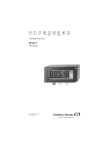
Brief Operating Instructions
Ecograph T
Multi Channel Recorder RSG30
Display, record & communicate
;
Seite 2
<
Page 20
=
Page 38
KA199R/09/a3/13.10
No.: 51009566
Software
ETU00xA, V2.02.xx
Kurzübersicht
Für die schnelle und einfache Inbetriebnahme:
1. Beachten Sie die Sicherheitshinweise
Seite 5
2. Montieren Sie das Gerät
Seite 7
3. Verdrahten Sie das Gerät
Seite 9
4. Installieren Sie die PC-Bediensoftware
Seite 16
5. Verbinden Sie das Gerät mit dem PC
Seite 16
6. Parametrieren Sie das Gerät (über PC)
Seite 17
7. Übertragen Sie die Setupdaten auf das Gerät
Seite 17
Integrierte Bedienungsanleitung
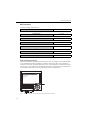
Ihr neues Gerät hat die Bedienungsanleitung eingebaut! Das einfache Bedienkonzept des
Gerätes erlaubt für viele Anwendungen eine Inbetriebnahme praktisch ohne Papier. Ihr Gerät
zeigt Bedienungshinweise auf Knopfdruck direkt am Bildschirm an! Trotzdem ist diese Beschreibung im Lieferumfang des Gerätes enthalten - sie ist die Ergänzung zu der im Gerät eingebauten
Bedienungsanleitung. Hier wird erläutert, was nicht direkt durch Klartext oder Auswahllisten
am Gerät beschrieben ist.
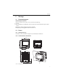
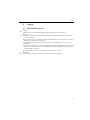
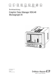
E
Abb. 1: Variable "Softkey" Taste (z.B. zum Aufruf der internen Hilfe-Funktion im Setup-Modus)
Diese Anleitung ist eine Kurzanleitung. Ausführliche Informationen entnehmen Sie
der Betriebsanleitung und den zusätzlichen Anleitungen auf der mitgelieferten
CD-ROM.
Diese Kurzanleitung ersetzt nicht die zum Lieferumfang gehörenden Betriebsanleitungen!
Die komplette Gerätedokumentation besteht aus:
• der vorliegenden Kurzanleitung
• einer CD-ROM mit PDF-Dateien der:
– Betriebsanleitung
– Grundlagen Messprinzip
– Zulassungs- und Sicherheitszertifikate
Inhaltsverzeichnis
1
Sicherheitshinweise . . . . . . . . . 5
1.1
1.2
1.3
1.4
Bestimmungsgemäße Verwendung . . . . . . .
Montage, Inbetriebnahme und Bedienung .
Betriebssicherheit . . . . . . . . . . . . . . . . . . . .
Sicherheitszeichen und -symbole . . . . . . . .
2
Identifizierung. . . . . . . . . . . . . . 6
2.1
Lieferumfang . . . . . . . . . . . . . . . . . . . . . . . 6
3
Montage . . . . . . . . . . . . . . . . . . 7
3.1
3.2
3.3
Einbaubedingungen . . . . . . . . . . . . . . . . . . 7
Einbau . . . . . . . . . . . . . . . . . . . . . . . . . . . . 7
Mechanische Verriegelung . . . . . . . . . . . . . 8
4
Verdrahtung . . . . . . . . . . . . . . . 9
4.1
4.2
4.3
Verdrahtung auf einen Blick . . . . . . . . . . . . 9
Klemmenbelegung . . . . . . . . . . . . . . . . . . 13
Schutzart . . . . . . . . . . . . . . . . . . . . . . . . . 13
5
Inbetriebnahme und Bedienung
. . . . . . . . . . . . . . . . . . . . . . . . 14
5.1
5.2
5.3
5.4
Funktionen - Handhabung im Betrieb . . . .
Bediensprache einstellen . . . . . . . . . . . . .
Inbetriebnahme . . . . . . . . . . . . . . . . . . . .
Kommunikation, PC Software installieren .
4
5
5
5
6
14
15
16
16
Sicherheitshinweise
1
Sicherheitshinweise
1.1
Bestimmungsgemäße Verwendung
Dieses Gerät ist für die elektronische Erfassung, Anzeige, Aufzeichnung, Auswertung, Fernübertragung und Archivierung von analogen und digitalen Eingangssignalen in nicht explosionsgefährdeten Bereichen bestimmt.
• Das Gerät ist für den Einbau in eine Schalttafel oder einen Schaltschrank vorgesehen und darf
nur im eingebauten Zustand betrieben werden.
• Für Schäden aus unsachgemäßen oder nicht bestimmungsgemäßen Gebrauch haftet der Hersteller nicht. Wenn das Gerät unsachgemäß oder nicht bestimmungsgemäß eingesetzt wird,
können Gefahren von ihm ausgehen.
1.2
Montage, Inbetriebnahme und Bedienung
• Das Gerät darf nur von qualifiziertem und autorisiertem Fachpersonal (z. B. Elektrofachkraft)
unter strenger Beachtung dieser Anleitung, der einschlägigen Normen, der gesetzlichen Vorschriften und der Zertifikate (je nach Anwendung) eingebaut, angeschlossen, in Betrieb
genommen und gewartet werden.
• Das Fachpersonal muss diese Anleitung gelesen und verstanden haben und die Anweisungen
befolgen.
• Veränderungen und Reparaturen am Gerät dürfen nur vorgenommen werden, wenn dies in
der Betriebsanleitung ausdrücklich erlaubt wird.
• Beschädigte Geräte, von denen eine Gefährdung ausgehen könnte, dürfen nicht in Betrieb
genommen werden und sind als defekt zu kennzeichnen.
• Beachten Sie grundsätzlich die in Ihrem Land geltenden Vorschriften bezüglich Öffnen und
Reparieren von elektrischen Geräten.
1.3
Betriebssicherheit
• Das Gerät ist nach dem Stand der Technik betriebssicher gebaut und geprüft und hat das
Werk in sicherheitstechnisch einwandfreiem Zustand verlassen. Die einschlägigen Vorschriften und europäischen Normen sind berücksichtigt.
• Beachten Sie die technischen Daten auf dem Typenschild! Das Typenschild befindet sich an
der linken Gehäuseseite.
Tischversion
#
Warnung!
• Der Netzstecker darf nur in eine Steckdose mit Schutzkontakt eingeführt werden.
• Die Schutzwirkung darf nicht durch eine Verlängerungsleitung ohne Schutzleiter aufgehoben
werden.
• Relaisausgänge: U (max) = 30 V eff (AC) / 60 V (DC)
Störsicherheit
Die Messeinrichtung erfüllt die allgemeinen Sicherheitsanforderungen gemäß IEC 61010 und
die EMV-Anforderungen gemäß IEC 61326.
5
Identifizierung
1.4
Sicherheitszeichen und -symbole
Achten Sie in dieser Betriebsanleitung konsequent auf Sicherheitshinweise, die mit den folgenden Symbolen gekennzeichnet sind:
#
Warnung!
Dieses Symbol deutet auf Aktivitäten oder Vorgänge hin, die - wenn sie nicht ordnungsgemäß
durchgeführt werden - zu Verletzung von Personen, zu einem Sicherheitsrisiko oder zur Zerstörung des Gerätes führen können.
"
Achtung!
Dieses Symbol deutet auf Aktivitäten oder Vorgänge hin, die - wenn sie nicht ordnungsgemäß
durchgeführt werden - zu fehlerhaftem Betrieb oder zu Zerstörung des Gerätes führen können.
!
Hinweis!
Dieses Symbol deutet auf Aktivitäten oder Vorgänge hin, die - wenn sie nicht ordnungsgemäß
durchgeführt werden - einen indirekten Einfluss auf den Betrieb haben oder eine unvorhergesehene Gerätereaktion auslösen können.
ESD - Electrostatic discharge
Schützen Sie die Klemmen vor elektrostatischer Entladung. Ein Nichtbeachten kann zur Zerstörung von Teilen der Elektronik führen.
2
Identifizierung
2.1
Lieferumfang
•
•
•
•
•
•
•
•
•
Gerät (mit Klemmen, entsprechend Ihrer Bestellung)
4 Schraub-Befestigungsspangen
USB Kabel
Optional CompactFlash CF Karte (Karte nicht im Gerät, sondern liegt bei.)
PC Bedien- und Parametriersoftware auf CD-ROM
Lieferschein
Mehrsprachige Kurzanleitung in Papierform
Betriebsanleitung auf CD-ROM
Verriegelungsplatte
Fehlen Teile? Dann informieren Sie bitte Ihren Lieferanten!
6
Montage
3
Montage
3.1
Einbaubedingungen
Arbeitstemperaturbereich:
0 bis 50 °C (32 bis 122 °F), max. 75% rel. Feuchte ohne Betauung.
Achtung!
• Zur Vermeidung von Wärmestaus stellen Sie bitte stets ausreichende Kühlung des Gerätes
sicher.
• Abstand zu starken magnetischen Feldern einhalten.
• Umgebung frontseitig gemäß Geräte-Schutzart IP 54
3.2
Einbau
3.2.1 Montagewerkzeug
Zum Einbau in der Schalttafel ist lediglich ein Schraubendreher erforderlich.
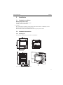
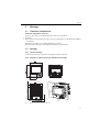
3.2.2 Schalttafeleinbau, Einbaumaße
144 mm
144 mm
21 mm
86,5 mm
137,9 mm
138 +1 mm
+1
138 mm
150 mm
X
36,1 mm
"
Y
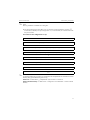
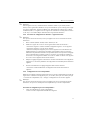
Abb. 2: Schalttafeleinbau und Einbaumaße
7
Montage
Einbautiefe: ca. 171 mm (6,73") (inkl. Anschlussklemmen und Befestigungsspangen)
Schalttafelausschnitt: 138+1 x 138+1 mm (5,43+0,04 x 5,43+0,04")
Schalttafelstärke: 2 bis 40 mm (0,08 bis 1,58")
Max. Blickwinkelbereich: von der Display-Mittelpunktachse 50° nach links und rechts, 20°
nach oben, 30° nach unten
Befestigung nach DIN 43 834
!
1.
Schieben Sie das Gerät von vorne durch den Schalttafelausschnitt. Zur Vermeidung von
Wärmestaus empfehlen wir einen Abstand von >15 mm (>0,59 inch) zu Wänden und
anderen Geräten.
2.
Das Gerät waagrecht halten und die Befestigungsspangen in die Aussparungen einhängen
(2 x oben, 2 x unten).
3.
Die Schrauben der Befestigungsspange gleichmäßig mit einem Schraubendreher anziehen,
so dass eine sichere Abdichtung zur Schalttafel gewährleistet ist.
Hinweis!
Eine Anreihbarkeit der Geräte in Y-Richtung (vertikal übereinander) ist nur mit einem Abstand
von min. 15 mm (0,59 inch) zwischen den Geräten möglich.
Eine Anreihbarkeit der Geräte in X-Richtung (horizontal nebeneinander) ist ohne Abstand
möglich.
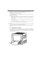
3.3
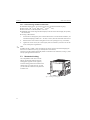
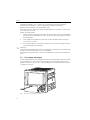
Mechanische Verriegelung
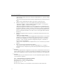
Die CompactFlash Karte kann mittels der mitgelieferten Verriegelungsplatte vor unbefugter Entnahme gesichert werden. Schieben Sie hierzu die Verriegelungsplatte in den Schlitz unter den
Griff der Abdeckklappe (s. Abb. 3). Nun können Sie mit einem passendem Schloss die Abdeckklappe verschließen bzw. verplomben.
Abb. 3: Einlegen der Verriegelungsplatte
8
Verdrahtung
#
"
!
4
Verdrahtung
4.1
Verdrahtung auf einen Blick
Warnung!
Beachten Sie, dass der gesamte elektrische Anschluss ausschließlich spannungsfrei vorgenommen werden darf.
Achtung!
• Die Schutzleiterverbindung ist vor allen anderen Verbindungen herzustellen. Bei Unterbrechung des Schutzleiters können Gefahren auftreten.
• Vergleichen Sie vor Inbetriebnahme die Übereinstimmung der Versorgungsspannung mit den
Angaben auf dem Typenschild (linke Gehäuseseite).
• Der gemischte Anschluss von Sicherheitskleinspannung und berührungsgefährlicher Spannung an den Relais ist nicht zulässig.
• Sehen Sie einen geeigneten Schalter oder Leistungsschalter in der Gebäudeinstallation vor.
Dieser Schalter muss in der Nähe des Gerätes (leicht erreichbar) angebracht und als Trennvorrichtung gekennzeichnet sein.
• Für die Netzleitung ist ein Überstromschutzorgan (Nennstrom 10 A) erforderlich.
Hinweis!
Beachten Sie auch den Anschlussklemmenplan auf der Rückseite des Gerätes.
9
Verdrahtung
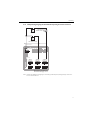
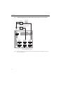
4.1.1 Schaltplan
Abb. 4: Schaltplan
10
Verdrahtung
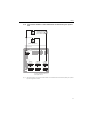
4.1.2 Hilfsspannungsausgang als Messumformerspeisung für 2-Leiter-Sensoren
+
Externer Anzeiger
(optional) z.B.
RIA261 von E+H
-
Y
+
_
Sensor 2
+
+
-
Y
Sensor 1
z.B. TR10 von E+H
_
Rel1
11
13
12
91
92
93
DI3
L+
NPE
Rel4 Rel3 Rel2
41
42
31
32
21
22
Out: max. 250 mA
Ethernet
GND
RxD/TxD +
RxD/TxD 611
612
613
614
615
616
CH 1
CH 2
CH 3
311
312
313
314
315
316
CH 6
511
512
513
514
515
516
CH 5
211
212
213
214
215
216
CH 4
411
412
413
414
415
416
RS485
RS232
1
111
112
113
114
115
116
5
6
9
Bei Anschluss von Kanal CH 1-4
siehe Steckerbelegung CH 5-6
Abb. 5: Anschluss des Hilfsspannungsausgangs bei Verwendung als Messumformerspeisung (MUS) für 2-Leiter-Sensoren im Strommessbereich
11
Verdrahtung
4.1.3 Hilfsspannungsausgang als Messumformerspeisung für 4-Leiter-Sensoren
Sensor 2
Ext. Anzeiger
(optional)
_
+
Y
+
z.B. RIA261 von E+H
Sensor 1 z.B. TR13 von E+H
_
+
Y
+
Rel1
11
13
12
91
92
93
DI3
L+
NPE
Rel4 Rel3 Rel2
41
42
31
32
21
22
Out: max. 250 mA
Ethernet
GND
RxD/TxD +
RxD/TxD 611
612
613
614
615
616
CH 1
CH 2
CH 3
311
312
313
314
315
316
CH 6
511
512
513
514
515
516
CH 5
211
212
213
214
215
216
CH 4
411
412
413
414
415
416
RS485
RS232
1
111
112
113
114
115
116
5
6
9
Bei Anschluss von Kanal CH 1-4
siehe Steckerbelegung CH 5-6
Abb. 6: Anschluss des Hilfsspannungsausgangs bei Verwendung als Messumformerspeisung (MUS) für 4-Leiter-Sensoren im Strommessbereich
12
Verdrahtung
4.2
"
Klemmenbelegung
Achtung!
Ist bei langen Signalleitungen mit energiereichen Transienten zu rechnen, empfehlen wir die
Vorschaltung eines geeigneten Überspannungsschutzes (z.B. E+H HAW560/562).
Verwenden Sie geschirmte Signalleitungen bei seriellen Schnittstellen!
4.2.1 Kabelspezifikation, Federklemmen
Sämtliche Anschlüsse auf der Geräterückseite sind als verpolungssichere Schraub- bzw. Federklemmblöcke ausgeführt. Somit ist ein sehr schneller und einfacher Anschluss möglich. Die
Federklemmen werden mit einem Schlitzschraubendreher (Größe 0) entriegelt.
Beim Anschluss ist folgendes zu beachten:
• Drahtquerschnitt Digital-I/O, RS485 und Analogeingänge: max. 1,5 mm2 (14 AWG) (Federklemmen)
• Drahtquerschnitt Netz: max. 2,5 mm2 (13 AWG) (Schraubklemmen)
• Drahtquerschnitt Relais: max. 2,5 mm2 (13 AWG) (Federklemmen)
• Abisolierlänge: 10 mm (0,39 inch)
!
Hinweis!
Beim Anschluss von flexiblen Leitungen an Federklemmen braucht keine Aderendhülse verwendet werden.
4.2.2 Anschluss der Schnittstellen
Ethernet, RS232/RS485 und USB-Anschluss
Details zum Anschluss der Schnittstellen finden Sie in der Betriebsanleitung auf CD-ROM, Kapitel 4.2.
4.3
Schutzart
Das Gerät erfüllt frontseitig alle Anforderungen gemäß Schutzart IP54.
13
Inbetriebnahme und Bedienung
5
Inbetriebnahme und Bedienung
5.1
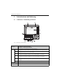
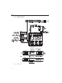
Funktionen - Handhabung im Betrieb
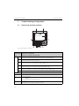
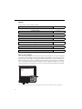
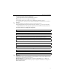
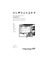
Abb. 7: Geräteanzeige / Bedieneinheiten
Bedienelement
(Pos.-Nr.)
1
Z
UT
V
W
F
Bedienfunktion
(Anzeigemodus = Messwertdarstellung)
(Setup-Modus = Bedienung im Setup-Menü)
Im Anzeigemodus: Schneller Rücksprung zum aktuellen Zeitpunkt
Im Setup-Modus: ESC-Taste zum Abbruch der Eingabe bzw. Rücksprung zum vorhergehenden Bild
Im Anzeigemodus: Schaltet zwischen verschiedenen Signaldarstellungen um (z.B. Bargraf,...)
Im Setup-Modus: Bewegt Cursor nach links bzw. rechts
Im Anzeigemodus: Spult Aufzeichnung zurück (Historiendarstellung - "Papier herausziehen")
Im Setup-Modus: Bewegt Markierungsbalken nach oben, ändert Parameter / (Vor-)Zeichen
Im Anzeigemodus: Spult Aufzeichnung wieder vor bis zum aktuellen Zeitpunkt ("Papier aufwickeln")
Im Setup-Modus: Bewegt Markierungsbalken nach unten, ändert Parameter / (Vor-)Zeichen
Im Anzeigemodus: Blendet Hauptmenü ein
Im Setup-Modus: ENTER-Taste "Eingabetaste" = Auswahl der markierten Funktion, Start der Parameteränderung
Variable "Softkey" Taste (z.B. Aufruf der internen Hilfe-Funktion im Setup-Modus)
1a
Funktionsanzeige der "Softkey" Taste
2
Steckplatz für CF Karte
14
Inbetriebnahme und Bedienung
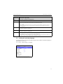
Bedienelement
(Pos.-Nr.)
2a
Bedienfunktion
(Anzeigemodus = Messwertdarstellung)
(Setup-Modus = Bedienung im Setup-Menü)
Taste zum Auswerfen der CF Karte
Achtung!
"
Nicht betätigen, wenn LED (2b) leuchtet! Gefahr von Datenverlust!
2b
LED am CF Steckplatz
LED leuchtet, wenn das Gerät auf die CF Karte schreibt, bzw. liest.
2c
USB-Buchse
3
Nur im Anzeigemodus: Fenster zur Messwertdarstellung
Anzeige der aktuellen Messwerte, je nach gewählter Signaldarstellung.
!
Hinweis!
Befindet sich eine Messstelle im Grenzwertzustand, wird die entsprechende Kanalbezeichnung rot hinterlegt dargestellt (schnelles Erkennen von Grenzwerten). Während Sie das Gerät bedienen läuft die Messwerterfassung ununterbrochen weiter.
4
Im Anzeigemodus: Anzeige aktuelles Datum / Uhrzeit
Im Setup-Modus: Anzeige der aktuellen Bedienposition
5
Im Anzeigemodus: Anzeige, welcher Anteil der CF Karte (in %) bereits beschrieben ist
Im Setup-Modus: Anzeige des aktuellen Bediencodes
6
Nur im Anzeigemodus: Funktionen der LED-Anzeigen auf dem Display (nach NAMUR NE44:)
• Grüne LED leuchtet: Spannungsversorgung OK, Gerät arbeitet störungsfrei
• Rote LED blinkt: Wartungsbedarf bei geräteexterner Ursache (z. B. Leitungsbruch etc.), bzw. es steht
eine zu quittierende Meldung / Hinweis an, Abgleich läuft.
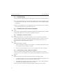
5.2
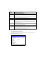
Bediensprache einstellen
Die Bediensprache ist auf Englisch (GB) voreingestellt. Eine andere Bediensprache kann im
Setup eingestellt werden.
F -> Set up -> Basic settings -> Language
Abb. 8: Ändern der Bediensprache
15
Inbetriebnahme und Bedienung
5.3
Inbetriebnahme
Nach Anlegen der Betriebsspannung leuchtet das Display und das Gerät ist funktionsbereit.
• Bei der Inbetriebnahme eines bereits konfigurierten oder voreingestellten Geräts werden die
Messungen sofort gemäß den Einstellungen begonnen. Im Display erscheinen die Werte der
aktuell eingestellten Anzeigegruppe.
• Bei der ersten Inbetriebnahme des Gerätes programmieren Sie das Setup gemäß den Beschreibungen der Betriebsanleitung auf CD-ROM, Kapitel 6.3.
5.4
!
Kommunikation, PC Software installieren
Hinweis!
Um eine Kommunikation zwischen Gerät und PC herstellen zu können, muss mindestens die
Version V1.23.0.0 (oder höher) der mitgelieferten PC Software installiert sein. Zur Sicherheit
sollten Sie die aktuelle PC Software (beiliegende CD-ROM) installieren.
5.4.1 Installation der mitgelieferten PC Software
!
Hinweis!
Zum Betrieb der mitgelieferten PC Software muss der "Arial Unicode MS™" Font an Ihrem PC
installiert sein. Ansonsten können gewisse Zeichen nicht oder falsch dargestellt werden. Überprüfen Sie dies an Ihrem PC unter "Systemsteuerung - Schriftarten". Sollte dieser Font nicht
installiert sein, lesen Sie bitte in Ihrem Microsoft-Office® bzw. Microsoft-Windows® Handbuch
nach.
!
Hinweis!
Zur Installation sind Administrator-Rechte erforderlich.
1.
Installieren Sie die mitgelieferte PC Software auf Ihrem Rechner. Bei Bedarf können Sie die
Bedienungsanleitung des Programms nach der Installation ausdrucken.
2.
Nach erfolgreicher Installation können Sie die PC Software unter "Start -> Alle Programme" aufrufen.
5.4.2 Kommunikation über USB / USB-Treiber Installation
Nach erfolgreicher Installation der mitgelieferten PC Software kann das Gerät mit einem
USB-Kabel am PC angeschlossen werden. Das Betriebssystem erkennt automatisch das neue
USB-Gerät.
!
16
Hinweis!
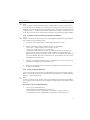
Zur anschließenden Installation des USB-Treibers gehen Sie wie folgt vor (betriebssystemabhängig):
1.
Das Windows-Fenster "Soll eine Verbindung mit Windows Update hergestellt werden, um
nach Software zu suchen?" quittieren Sie mit "Nein, diesmal nicht" und "Weiter".
2.
Das Windows-Fenster "Wie möchten Sie vorgehen?" quittieren Sie mit "Software automatisch installieren (empfohlen)" und "Weiter".
Inbetriebnahme und Bedienung
Nun können Sie die mitgelieferte PC Software starten, und eine Kommunikation mit dem Gerät
herstellen.
!
Hinweis!
In der mitgelieferten PC Software wird die USB-Schnittstelle wie ein COM-Port (serielle
Schnittstelle) angesprochen. Im Windows Geräte-Manager können Sie ermitteln, über welchen
COM-Port das Gerät angesprochen werden kann. Das Gerät wird im Geräte-Manager unter
"Anschlüsse (COM und LPT)" als "ETU00xA (Com x)" angezeigt. Die mitgelieferte PC Software
unterstützt die COM-Ports 1 bis 20 (ab Version V1.21.2.0), gegebenenfalls im Windows
Geräte-Manager die Zuordnung entsprechend heruntersetzen.
5.4.3 Vorgehensweise Setup per Schnittstelle und mitgelieferter PC-Software:
!
Hinweis!
Um diese Funktion nutzen zu können, muss das Gerät bereits in der PC-Datenbank angelegt
sein, bzw. zuerst neu angelegt werden.
1.
Geräteschnittstelle (RS232 / RS485, USB oder Ethernet) mit dem PC verbinden.
2.
PC Software starten und neues Gerät in der PC-Datenbank anlegen:
- Wählen Sie "Gerät -> Geräteeinstellungen anzeigen/ändern /neues Gerät"
- Wählen Sie "Gerät -> Neues Gerät einfügen"
- Vergeben Sie Gerätebeschreibungen für das neue Gerät. Zur Übertragung der Geräteeinstellungen wählen Sie die entsprechende Geräteschnittstelle aus. Gehen Sie auf "Weiter".
Wählen Sie die entsprechenden Schnittstellenparameter aus (muss mit den Einstellungen
zur Kommunikation am Gerät übereinstimmen). Gehen Sie auf "Weiter". Es wird eine
Zusammenfassung der Angaben zum neuen Gerät angezeigt. Mit "OK" wird eine Verbindung zum Gerät hergestellt und das neue Gerät in der PC-Datenbank angelegt.
3.
Passen Sie die Geräteeinstellungen an und wählen Sie "Fertig -> Einstellungen an das
Gerät senden". Die neuen Setup-Parameter werden automatisch auf das Gerät übertragen.
4.
Abschließend sollten die Geräteeinstellungen in der Gerätedatenbank gespeichert werden.
Wählen Sie "Fertig -> Einstellungen in der Gerätedatenbank speichern".
5.4.4 Setup per CompactFlash Karte
Speichern Sie die Geräteeinstellungen am PC über die mitgelieferte PC-Software auf die CompactFlash Karte. Dieses Setup-File kann, wenn freigegeben unter "Hauptmenü -> CompactFlash
(CF) Funktionen -> Setup von CF laden" in das Gerät übernommen werden.
!
Hinweis!
Um diese Funktion nutzen zu können, muss das Gerät bereits in der PC-Datenbank angelegt
sein, bzw. zuerst neu angelegt werden. Ausserdem muss ein CompactFlash Kartensteckplatz am
PC vorhanden sein.
17
Inbetriebnahme und Bedienung
Vorgehensweise Setup per CompactFlash Karte:
1.
Setup auf CompactFlash Karte kopieren:
- Legen Sie eine formatierte CompactFlash Karte ins Gerät ein.
- Wählen Sie im Hauptmenü "CompactFlash (CF) Funktionen -> Setup auf CF kopieren".
- Wählen Sie im Hauptmenü "CompactFlash (CF) Funktionen -> CF sicher entfernen".
- Entnehmen Sie die CompactFlash Karte aus dem Gerät und stecken Sie sie in den CompactFlash Kartensteckplatz im PC ein.
2.
PC Software starten und neues Gerät in der PC-Datenbank anlegen:
- Wählen Sie "Gerät -> Geräteeinstellungen anzeigen/ändern /neues Gerät"
- Wählen Sie "Gerät -> Neues Gerät einfügen"
- Vergeben Sie Gerätebeschreibungen für das neue Gerät. Zur Übertragung der Geräteeinstellungen wählen Sie "Parameterdatei von einem Datenträger (z.B. Diskette, ATA-Flash)".
Gehen Sie auf "Weiter". Wählen Sie die entsprechende Geräte-Parameterdatei (*.rpd) von
der CF-Karte aus. Gehen Sie auf "Weiter". Es wird eine Zusammenfassung der Angaben
zum neuen Gerät angezeigt. Mit "OK" wird das neue Gerät in der PC-Datenbank angelegt.
3.
Setup im PC-Programm anpassen und in der zugehörigen Datenbank speichern:
- Passen Sie die Geräteeinstellungen an.
- Wählen Sie "Fertig -> Einstellungen in der Gerätedatenbank speichern". Die neuen
Setup-Parameter werden in der PC-Datenbank gespeichert. Übertragen Sie das neue
SETUP-File auf die CompactFlash Karte in Ihrem PC: "Fertig -> Setup-Datenträger
erstellen (Diskette / ATA-Flash)" wählen und passendes Laufwerk selektieren.
- Entnehmen Sie die CompactFlash Karte aus dem Steckplatz im PC und legen Sie sie in
das Gerät ein.
4.
Neues Setup direkt am Gerät einlesen:
- Wählen Sie im Hauptmenü "CompactFlash (CF) Funktionen -> Setup von CF laden".
Wiederholen Sie diesen Vorgang, um auch weitere Geräte mit diesem Setup zu parametrieren.
"
Achtung!
Wird diese Setup-CompactFlash Karte nicht entnommen, beginnt nach ca. 5 Minuten die Messdatenspeicherung. Die Setup-Daten bleiben weiterhin erhalten. Bitte die CompactFlash Karte
wechseln, wenn die Messdaten nicht auf dieser gespeichert werden sollen.
"
Achtung!
Eine sichere Funktion ist nur mit der Original CompactFlash Karte des Herstellers gewährleistet.
5.4.5 Setup direkt am Gerät (über Tastatur)
•
•
•
•
18
Drücken Sie F. Es erscheint das Hauptmenü.
Wählen Sie mit V oder W das gewünschte Kapitel
Bestätigen Sie mit F
Mit der "Softkey-Taste" kann zu dem ausgewählten Eintrag eine Hilfe angezeigt werden.
Inbetriebnahme und Bedienung
Tastenfunktion im Setup
Z Abbruch der Eingabe bzw. Rücksprung zu vorhergehendem Bild.
UT Bewegt Cursor nach links bzw. rechts.
VW Bewegt Markierungsbalken nach oben bzw. unten, ändert Parameter / (Vor-)Zeichen.
F: Enter-Taste = Auswahl der markierten Funktion, Start der Parameteränderung.
!
Hinweis!
• Jeder Parameter wird über ein Dialogfenster geändert.
• Die geänderten Einstellungen werden erst wirksam, wenn Sie durch mehrmaliges Drücken
von Z wieder in den Normalbetrieb zurückkehren (Übernahme mit F bestätigen). Bis zu
diesem Zeitpunkt arbeitet das Gerät noch mit den vorherigen Daten.
Vorgehensweise zur Gerätekonfiguration / Setup:
Start
Grundeinstellungen (Sprache, Datum/Zeit, Speicherzyklus, CompactFlash, usw.)
Signaleinstellungen zu den Analogeingängen (Signaltyp, Eingangsbereich, usw.)
Signaleinstellungen zu den Digitaleingängen (Funktion, Bezeichnung, usw.)
Signaleinstellungen der Grenzwerte und Alarmrelais (falls notwendig)
Signaleinstellungen zu den Relais (Betriebsart, Bezeichnung, usw.)
Einstellungen zur Kommunikation (USB/RS232/RS485/Ethernet)
Ende
!
Hinweis!
Nach der Inbetriebnahme (Geräte-Setup) sollte die CF Karte und der interne Speicher gelöscht
werden, um die temporären Setupdaten zu löschen!
CF Karte löschen: F Hauptmenü -> CompactFlash (CF) Funktionen -> CF löschen
Internen Speicher löschen: F Hauptmenü -> Diagnose/Geräteinformationen -> Internen
Speicher löschen
19
Multi Channel Recorder
Brief overview
For quick and easy commissioning:
1. Consider the safety instructions
Page 23
2. Install the unit
Page 25
3. Wire up the unit
Page 27
4. Install the provided PC software
Page 34
5. Connect the unit with the PC
Page 35
6. Set up the unit (via provided PC software)
Page 35
7. Transmit the set up files to the unit
Page 35
Brief Operating Instructions
Your new unit has the Operating Instructions built-in. The unit's simple control system enables
you to commission for many applications, practically without any paper. Your unit displays
instructions at the push of a button directly on screen. This description is nevertheless delivered
with the unit - it is a supplement to the Operating Instructions built into the unit. Anything that
is not described directly at the unit by plain text or menus is explained here.
E
Fig. 1: Variable softkey (e.g. calling up internal Help function in the Setup menu)
20
Multi Channel Recorder
This document constitutes the Brief Operating Instructions. More detailed information
can be found in the Operating Instructions and the additional instructions on the
CD-ROM supplied.
These Brief Operating Instructions do not act as a substitute for the Operating Instructions
included in the scope of supply!
The complete device documentation comprises:
• These Brief Operating Instructions
• A CD-ROM with PDF files of:
– Operating Instructions
– Measuring principle fundamentals
– Approval and safety certificates
21
Multi Channel Recorder
Table of contents
1
Safety instructions. . . . . . . . . . 23
1.1
1.2
1.3
1.4
Designated use . . . . . . . . . . . . . . . . . . . . .
Installation, commissioning and operation .
Operational safety . . . . . . . . . . . . . . . . . . .
Notes on safety conventions and icons . . .
2
Identification . . . . . . . . . . . . . . 24
2.1
Scope of delivery . . . . . . . . . . . . . . . . . . . 24
3
Installation . . . . . . . . . . . . . . . 25
3.1
3.2
3.3
Installation conditions . . . . . . . . . . . . . . . 25
Installation instructions . . . . . . . . . . . . . . 25
Mechanical locking . . . . . . . . . . . . . . . . . 26
4
Wiring . . . . . . . . . . . . . . . . . . . 27
4.1
4.2
4.3
Quick wiring guide . . . . . . . . . . . . . . . . . 27
Terminal assignment . . . . . . . . . . . . . . . . 30
Degree of protection . . . . . . . . . . . . . . . . . 31
5
Commissioning and operation 32
5.1
5.2
5.3
5.4
Display and operating elements . . . . . . . . .
Setting the operating language . . . . . . . . .
Commissioning . . . . . . . . . . . . . . . . . . . .
Communication; PC software installation .
22
23
23
23
24
32
33
34
34
Multi Channel Recorder
1
Safety instructions
1.1
Designated use
Safety instructions
This device is designed for the electronic acquisition, display, recording, analysis, remote transmission and archiving of analog and digital input signals in non-hazardous areas.
• The device is designed for installation in a panel or a cabinet and may only be operated in an
installed state.
• The manufacturer does not accept liability for damage caused by improper or non-designated
use. The device can cause danger if used improperly or other than intended.
1.2
Installation, commissioning and operation
• The device may only be installed, connected, commissioned and serviced by qualified and
authorized expert staff (e.g. electrical technicians) strictly adhering to the instructions contained in this manual, the applicable norms, legal regulations and certificates (depending on
the application).
• These experts must have read and understood this manual and follow the instructions it contains.
• The device may only be modified or repaired if expressly permitted in the Operating Instructions.
• Damaged devices which could pose a source of danger may not be put into operation and must
be marked as defective.
• Primarily observe local regulations regarding opening and repairing electrical devices.
1.3
Operational safety
• The device is safely built and tested according to state-of-the-art technology and has left the
factory in perfect condition as regards technical safety. The applicable regulations and European standards have been taken into account.
• Please observe the technical data on the nameplate! The nameplate is on the left-hand side of
the housing.
Desk top version
#
Warning!
• The mains plug must only be inserted into a socket with grounding contact.
• The protective effect must not be removed by an extension lead without ground wire.
• Relay outputs: U(max) = 30 V eff (AC) / 60 V (DC)
Electromagnetic compatibility
The measuring system meets the general safety requirements of IEC 61010 and the EMC
requirements of IEC 61326.
23
Identification
1.4
Multi Channel Recorder
Notes on safety conventions and icons
Always refer to the safety instructions in these Operating Instructions labeled with the following
symbols:
#
Warning!
This symbol draws attention to activities or procedures that can lead to injuries to persons, safety
risks or the destruction of the device if not carried out properly.
"
Caution!
This symbol draws attention to activities or procedures that can lead to defective operation or to
destruction of the device if not carried out properly.
!
Note!
This symbol draws attention to activities or procedures that have an indirect effect on operation,
or can trigger an unforeseen device reaction if not carried out properly.
ESD – Electrostatic discharge
Protect the terminals against electrostatic discharge. Failure to comply with this instruction can
result in the destruction of parts of the electronics.
2
Identification
2.1
Scope of delivery
•
•
•
•
•
•
•
•
•
Device (with terminals, as per your order)
4 fastening clips
USB cable
Optional CompactFlash CF card (CF card is enclosed separately.)
PC operating and configuration software on CD-ROM
Delivery note
Multilanguage Brief Operating Instructions as hard copy
Operating Instructions on CD-ROM
locking plate
Anything missing? Then please inform your supplier.
24
Multi Channel Recorder
Installation
3
Installation
3.1
Installation conditions
Working temperature range:
0 to 50 °C (32 to 122 °F), max. 75% rel.
humidity without condensation.
Caution!
• To avoid heat accumulation, please always ensure that the device is sufficiently cooled.
• Observe distance from strong magnetic fields.
• Environment at front in accordance with device ingress protection IP 54.
3.2
Installation instructions
3.2.1 Mounting tool
To install the control panel, all you need is a screwdriver.
144 mm
5.67”
144 mm
5.67”
21 mm
0.83”
86.5 mm
3.4”
137.9 mm
5.43”
138 +1 mm
5.43 +0.04 “
138 mm
+0.04
“
5.43
150 mm
5.9”
+1
X
36.1 mm
1.42”
"
Y
Fig. 2: Panel mounting and installation dimensions
25
Installation
Multi Channel Recorder
3.2.2 Panel mounting, installation dimensions
•
•
•
•
Installation depth: approx. 171 mm (6.73 inch) (incl. terminals and fastening clips)
Panel cutout: 138+1 x 138+1 mm (5.43+0.04 x 5.43+0.04 inch)
Panel thickness: 2 to 40 mm (0.08 to 1.57 inch)
Maximum point of view range: From the display center 50° to the left and right, 20° upward,
30° downward.
• Securing to DIN 43 834
!
1.
Push the device through the panel cutout from the front. To avoid heat accumulation, we
recommend keeping a distance of > 15 mm (> 0.59 in) from the walls and other devices.
2.
Hold the device level and then hang jack screws in the openings (2 x top, 2 x bottom).
3.
Tighten the screws on the jack screws equally with a screwdriver, such that a secure seal
to the control panel is guaranteed.
Note!
A distance of min. 15 mm (> 0.59 in) between the devices has to be observed if aligning the
devices in the Y-direction (see Fig. 2, vertically above one another).
The devices can be arranged horizontally beside one another in the X direction (see Fig. 2) without any spacing between the devices.
3.3
Mechanical locking
The CompactFlash card can be secured
against unauthorized removal using the
locking plate supplied. For this purpose,
insert the locking plate into the slit below the
handle of the cover plate (see Fig. 3). Now
you can lead-seal or seal the cover plate with
a suitable lock.
Fig. 3: Inserting the locking plate
26
Multi Channel Recorder
4
Wiring
4.1
Quick wiring guide
Wiring
#
Warning!
Please note that the entire electrical connection may only take place when the device is de-energized.
"
Caution!
• The ground connection must be made before all other connections. Any interruption in the
ground can cause danger.
• Before commissioning, compare the supply voltage with the information specified on the
nameplate (left-hand side of the housing).
• The mixed connection of safety extra-low voltage and dangerous contact voltage to the relay
is not permitted.
• Provide a suitable switch or circuit breaker when installing in a building. This switch must be
installed near to the device (easily accessible) and be labeled as a separator.
• An overcurrent protective device (nominal current 10 A) is required for the power cable.
!
Note!
Please also refer to the terminal diagram on the rear of the device.
27
Wiring
Multi Channel Recorder
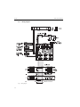
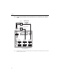
4.1.1 Wiring diagram
Fig. 4: Wiring diagram
28
Multi Channel Recorder
Wiring
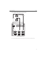
4.1.2 Auxiliary voltage output for 2-wire sensors
+
External display
(optional) e.g.
RIA261 from E+H
-
Y
+
_
Sensor 2
+
+
-
Y
Sensor 1
e.g. TR10 from E+H
_
Rel1
11
13
12
91
92
93
DI3
L+
NPE
Rel4 Rel3 Rel2
41
42
31
32
21
22
Out: max. 250 mA
Ethernet
GND
RxD/TxD +
RxD/TxD 611
612
613
614
615
616
CH 1
CH 2
CH 3
311
312
313
314
315
316
CH 6
511
512
513
514
515
516
CH 5
211
212
213
214
215
216
CH 4
411
412
413
414
415
416
RS485
RS232
1
111
112
113
114
115
116
5
6
9
On connecting channels 1-4 see
terminal connections CH 5-6
Fig. 5: Using the auxiliary voltage output as power supply for 2-wire sensors (at current measurement range)
29
Wiring
Multi Channel Recorder
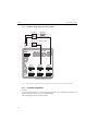
4.1.3 Auxiliary voltage output for 4-wire sensors
Sensor 2
Ext. display
(optional)
_
+
Y
+
e.g. RIA261 from E+H
Sensor 1 e.g. TR13 from E+H
_
+
Y
+
Rel1
11
13
12
91
92
93
DI3
L+
NPE
Rel4 Rel3 Rel2
41
42
31
32
21
22
Out: max. 250 mA
Ethernet
GND
RxD/TxD +
RxD/TxD 611
612
613
614
615
616
CH 1
CH 2
CH 3
311
312
313
314
315
316
CH 6
511
512
513
514
515
516
CH 5
211
212
213
214
215
216
CH 4
411
412
413
414
415
416
RS485
RS232
1
111
112
113
114
115
116
5
6
9
On connecting channels 1-4 see
terminal connections CH 5-6
Fig. 6: Using the auxiliary voltage output as power supply for 4-wire sensors (at current measurement range)
4.2
"
30
Terminal assignment
Caution!
If high-energy transients occur when using long signal cables, we recommend connecting a suitable overvoltage protection (e.g. E+H HAW560/562).
Use shielded signal lines for serial interfaces!
Multi Channel Recorder
Wiring
4.2.1 Cable specification, Spring terminals
All connections on the rear of the device are designed as screw or spring terminal blocks with
reverse polarity protection. This makes the connection very quick and easy. The spring terminals
are unlocked with a slotted screwdriver (size 0).
Please note the following when connecting:
• Digital I/O wire cross-section, RS485 and analog inputs: max. 1.5 mm2 (14 AWG) (spring
terminals)
• Power supply wire cross-section: max. 2.5 mm2 (13 AWG) (screw terminals)
• Relay wire cross-section: max. 2.5 mm2 (13 AWG) (spring terminals)
• Stripping length: 10 mm (0.39 in)
!
Note!
No ferrules have to be used when connecting flexible wires to spring terminals.
4.2.2 Connecting the interfaces
Ethernet, RS232/RS485 and USB connection
Details on connecting the interfaces can be found in the Operating Instructions on CD-ROM,
chapter 4.2.
4.3
Degree of protection
At the front, the device meets all the requirements of ingress protection IP54.
31
Commissioning and operation
5
Commissioning and operation
5.1
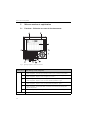
Display and operating elements
Multi Channel Recorder
Fig. 7: Device display / control units
Operating
element (Item
No.)
1
Z
U
T
V
W
F
Operating function
(Display mode = Signal display)
(Setup menu = Operation in the Setup menu)
At display mode: Quick return to current time
At Setup menu: ESC key to abort the input and/or quick return to the preceding display.
At display mode: Changes between the various display modes (e.g. bargraph,...)
At Setup menu: Moves the cursor to left or right
At display mode: Rewinds recording (history display - "remove paper")
At Setup menu: Moves the cursor bar upwards, changes parameter / signs
At display mode: Forwards recording to current time ("wind on paper")
At Setup menu: Moves the cursor bar downwards, changes parameter / signs
At display mode: Displays main menu
At Setup menu: ENTER key = Selection of the marked function, start the parameter change
Variable softkey (e.g. calling up internal Help function in the Setup menu)
1a
Function indicator of the softkey
2
Slot for CF card
2a
Key to eject the CF card
"
Caution!
Do not actuate if LED (2b) is lit! Risk of data loss!
2b
32
LED at CF slot
LED lights up if the unit is reading or writing to the CF card.
Multi Channel Recorder
Operating
element (Item
No.)
Operating function
(Display mode = Signal display)
(Setup menu = Operation in the Setup menu)
2c
USB socket
3
At display mode: Window for measured value display
Displays the current measured values depending on the signal display selected.
Commissioning and operation
!
Note!
If a measuring point has limit value status, the corresponding channel identifier is displayed in red (quick
detection of limit values). When you are operating the unit, measured value acquisition continues to run
without interruption.
4
At display mode: Displays the current date/time
At Setup menu: Displays the operating item
5
At display mode: Indicates what portion of the CF card is already written to (in %)
At Setup menu: Displays the operating code
6
At display mode: Functions of the LED displays on the display (as per NAMUR NE44:)
• Green LED lights up: power supply OK, unit working without faults
• Red LED flashes: need for maintenance if unit-external problem occurs (e.g. cable open circuit etc.) or a
message / note to be acknowledged is pending, calibration in progress.
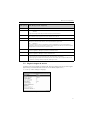
5.2
Setting the operating language
The default setting for the operating language is English (GB). A different operating language can
be configured in the set up.
F -> Set up -> Basic settings -> Language
Fig. 8: Change the operating language
33
Commissioning and operation
5.3
Multi Channel Recorder
Commissioning
Once the operating voltage is applied, the display lights up and the unit is ready for operation.
• If you are commissioning a unit that is already configured, measuring is immediately started
in accordance with the settings. The values of the display group currently configured appear
on the display.
• When you first commission the unit, program the set up in accordance with the description
in the Operating Instructions on CD-ROM, chapter 6.3.
5.4
!
Communication; PC software installation
Note!
The current PC operating software (CD-ROM supplied) must be installed to be able to establish
communication between the unit and the PC (minimum V1.23.0.0).
5.4.1 Installing the provided PC software
!
Note!
The "Arial Unicode MS™" font must be installed on your PC to operate the provided PC
software. Otherwise certain characters might be displayed incorrectly or not at all. Check this
on your PC under "Control Panel - Fonts". If this font is not installed, please refer to your
Microsoft Office® or Microsoft Windows® manual.
!
Note!
Administrator rights are required!
1.
Install the supplied PC software on your computer. The program's Operating Instructions
can be printed out after installation, if required.
2.
After the successful installation you can call up the program under "Start - Programs".
5.4.2 Communication via USB / USB driver installation
Once the provided PC operating software has been installed successfully, the unit can be
connected to the PC with a USB cable. The operating system automatically recognizes the new
USB unit.
!
Note!
Proceed as follows to then install the USB driver (depends on operating system):
1.
The Windows prompt "Should a connection be established with Windows Update to look
for software?" appears. Click "No, not this time" and then "Next".
2.
The "What do you want the wizard to do?" window appears. Select "Install the software
automatically (Recommended)" and then click "Next".
You can now start the provided PC software to establish communication with the unit.
34
Multi Channel Recorder
!
Commissioning and operation
Note!
In the provided PC software, the USB interface is addressed like a COM port (serial interface).
In the Windows device manager, you can determine the COM port via which the unit can be
addressed. The unit is displayed in the device manager under "Connections (COM and LPT)" as
"ETU00xA (Com x)". The provided PC software supports the COM-ports 1 to 20 (from version
V1.21.2.0), if necessary reduce the allocation accordingly in the Windows equipment manager.
5.4.3 Procedure set up via interface and provided PC software
!
Note!
In order to be able to use this function, the unit must already be registered in the PC database,
and/or register in the PC database at first.
1.
Connect the unit interface (RS232 / RS485, USB or Ethernet) to the PC.
2.
Start the provided PC software and add new unit in the PC database:
- Select "Unit -> Display/change unit set-up/add new unit"
- Select "Unit -> Add new unit" in the new window.
- Assign general informations for the new unit. Select the interface for the unit set up.
Select "Continue". Select the appropriate interface parameters (must agree with the
attitudes to communication on the unit). Select "Continue". A summary of the data to the
new unit is indicated. With "OK" a connection to the unit is made and the new unit will
be registered in the PC data base.
3.
Adjust the unit settings and select "Finished -> Transmit set-up to unit". The new set up
parameters are automatically transferred to the unit.
4.
Finally, the unit settings should be saved in the unit database. Select "Finished -> Store
set-up into unit database".
5.4.4 Set up via CompactFlash card
Save the unit settings on the PC onto the CompactFlash card using the provided PC software.
This set up file can be adopted into the unit if released under "Main menu -> CompactFlash (CF)
functions -> Load set-up from CF".
!
Note!
In order to be able to use this function, the unit must already be registered in the PC database,
and/or register in the PC database at first. In addition a CompactFlash card slot must be present
at the PC.
Procedure set up via CompactFlash card:
1.
Copy set up to CompactFlash card:
- Insert a formatted CompactFlash card into the unit.
- In the main menu, select "CompactFlash (CF) functions -> Copy set-up to CF".
- In the main menu, select "CompactFlash (CF) functions -> Safely remove CF".
35
Commissioning and operation
Multi Channel Recorder
- Remove the CompactFlash card from the unit and insert it into the CompactFlash card
slot in the PC.
2.
Start the provided PC software and add new unit in the PC database:
- Select "Unit -> Display/change unit set-up/add new unit"
- Select "Unit -> Add new unit" in the new window.
- Assign general informations for the new unit. Select "Parameter file from a data source
(e.g. diskette, ATA flash card)". Select "Continue". Select the appropriate parameter file
(*.rpd) from the CompactFlash card. Select "Continue". A summary of the data to the new
unit is indicated. With "OK" the new unit will be registered in the PC data base.
3.
Adjust set up in the provided PC software and save in the associated database:
- Adjust the unit settings.
- Select "Finished -> Store set-up into unit data base". The new set up parameters are saved
in the PC database. Transfer the new set up file to the CompactFlash card in your PC:
select "Finished -> Create set-up data carrier (diskette/ATA flash card)" and select the
suitable CompactFlash card slot.
- Remove the CompactFlash card from the slot in the PC and insert it into the unit.
4.
Read the new set up into one (or more) unit(s):
- In the main menu, select "CompactFlash (CF) functions -> Load set-up from CF". Repeat
this procedure, to set up further units with this parametrization.
"
Caution!
If the set up CompactFlash card is not removed, the measurement data will begin to be saved
after approx. 5 minutes. The set up data is still kept. Please change the CompactFlash card if the
measurement data is not meant to be saved onto this card.
"
Caution!
Correct and safe functioning is only guaranteed with genuine CompactFlash cards of the
manufacturer.
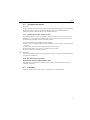
5.4.5 Set up direct at the unit (via unit keyboard)
• Press F. The main menu appears.
• With V or W select the desired chapter
• Confirm with F
• Use the softkey to call up the Help on the entry selected.
Key function in set up
Z Cancel entries or return to previous screen.
UT Moves cursor left or right.
VW Moves bar up or down, changes parameter/sign.
F: Enter key = selects the highlighted function, starts parameter change.
36
Multi Channel Recorder
!
Commissioning and operation
Note!
• Every parameter is modified via a dialog box.
• The altered settings only take effect once you return to normal operation by pressing Z
several times (confirm you accept changes with F ). Until this time, the unit still works with
the previous data.
Procedure for unit configuration/set up:
Start
Basic settings (language, date/time, save cycle, CompactFlash, etc.)
Signal settings for the analog inputs (signal type, input range, etc.)
Signal settings for the digital inputs (function, designation, etc.)
Signal settings of the set points and alarm relays (if necessary)
Signal settings for the relays (operating mode, description, etc.)
Communication settings (USB/RS232/RS485/Ethernet)
End
!
Note!
To delete the temporary set up files you should delete the CompactFlash CF card and the internal
memory after the commissioning (unit set up).
Delete CF: F Main menu -> CompactFlash (CF) functions -> Delete CF
Delete internal memory: F Main menu -> Diagnostic/unit information -> Delete internal
memory
37
Aperçu
Pour une mise en service simple et rapide :
1. Tenir compte des conseils de sécurité
page 41
2. Monter l'appareil
page 43
3. Relier l'appareil
page 45
4. Installer le logiciel PC
page 52
5. Relier l'appareil au PC
page 53
6. Paramétrer l'appareil (via PC)
page 53
7. Transférer les données de configuration dans l'appareil
page 53
Mise en service intégrée
Votre nouvel appareil possède un manuel de mise en service intégré ! Le concept de configuration simple de votre appareil permet, pour de nombreuses applications, une mise en service pratiquement sans manuel papier. Votre appareil affiche directement des conseils d'utilisation sur
simple activation d'une touche. Cependant le présent manuel est aussi fourni avec le matériel
livré - il est complémentaire des conseils de mise en service intégrés à l'appareil. Vous y trouverez des explications qui ne figurent pas en texte clair ou dans des listes de sélection de l'appareil.
E
Fig. 1 : Touche des variables (par ex. pour l'interrogation de la fonction d'aide interne en mode de configuration)
38
Il s'agit là d'instructions condensées. Des informations détaillées figurent dans le
manuel de mise en service et dans les autres documentations sur le CD-ROM fourni.
Les présentes instructions ne remplacent pas le manuel de mise en service fourni !
La documentation complète pour l'appareil comprend :
• les présentes instructions condensées
• un CD-ROM avec les fichiers PDF suivants :
Manuel de mise en service
Bases du principe de mesure
Agréments et certificats
39
Sommaire
1
Conseils de sécurité . . . . . . . . 41
1.1
1.2
1.3
1.4
Utilisation conforme à l'objet . . . . . . . . . .
Montage, mise en service et utilisation . . .
Sécurité de fonctionnement . . . . . . . . . . .
Symboles de sécurité utilisés . . . . . . . . . . .
2
Identification . . . . . . . . . . . . . . 42
2.1
Ensemble livré . . . . . . . . . . . . . . . . . . . . . 42
3
Montage . . . . . . . . . . . . . . . . . 43
3.1
3.2
3.3
Conditions d'implantation . . . . . . . . . . . . 43
Montage . . . . . . . . . . . . . . . . . . . . . . . . . 43
Verrouillage mécanique . . . . . . . . . . . . . . 44
4
Câblage . . . . . . . . . . . . . . . . . . 45
4.1
4.2
4.3
Raccordement en bref . . . . . . . . . . . . . . . . 45
Occupation des bornes . . . . . . . . . . . . . . . 49
Protection . . . . . . . . . . . . . . . . . . . . . . . . 49
5
Mise en service et exploitation 50
5.1
Fonctions - Utilisation en cours de
fonctionnement . . . . . . . . . . . . . . . . . . . .
Régler la langue de service . . . . . . . . . . . .
Mise en service . . . . . . . . . . . . . . . . . . . .
Communication, installer le logiciel PC . . .
5.2
5.3
5.4
40
41
41
41
42
50
51
52
52
Conseils de sécurité
1
Conseils de sécurité
1.1
Utilisation conforme à l'objet
Le présent appareil est destiné à la mesure, l'affichage, la représentation, l'exploitation, la transmission à distance et l'archivage de signaux d'entrée analogiques et digitaux en zones non explosibles.
• L'appareil est prévu pour un montage en armoire électrique et ne doit être exploité qu'après
avoir été installé.
• La garantie du fabricant ne couvre pas les dommages résultant d'une utilisation non conforme
à l'objet. Si l'appareil n'est pas utilisé de manière conforme, il peut être source de dangers.
1.2
Montage, mise en service et utilisation
• L'appareil ne doit être installé, raccordé, mis en service et entretenu que par un personnel
spécialisé, qualifié et autorisé (par ex. électricien) qui respectera strictement les présentes
instructions, les normes en vigueur, les directives locales et les certificats (selon l'application).
• Le personnel spécialisé doit impérativement avoir lu, compris et suivi les présentes instructions.
• Des modifications et réparations de l'appareil peuvent uniquement être effectuées si ceci est
expressément spécifié dans les instructions.
• Les appareils endommagés qui pourraient constituer une source de dangers ne doivent pas
être mis en service et être marqués comme défectueux.
• Tenir compte des réglementations nationales en matière d'ouverture et de réparation d'appareils électriques.
1.3
Sécurité de fonctionnement
• L'appareil a été construit d'après les derniers progrès techniques et a quitté nos établissements
dans un état irréprochable. Les directives et normes européennes en vigueur ont été respectées.
• Tenir compte des caractéristiques techniques sur la plaque signalétique ! La plaque signalétique se trouve sur la paroi gauche de l'appareil.
Version de table
#
Danger !
• Le connecteur de réseau ne doit être inséré que dans une prise avec fiche de terre.
• La protection ne doit pas être supprimée par l’emploi d’un câble prolongateur sans fil de terre.
• Sorties relais : U (max) = 30 V eff (AC) / 60 V (DC)
Protection contre les parasites
L'ensemble de mesure remplit toutes les exigences générales de sécurité selon CEI 61010 ainsi
que les exigences CEM selon CEI 61326
41
Identification
1.4
Symboles de sécurité utilisés
Veuillez observer les remarques sur les éventuels dangers mis en évidence par les pictogrammes
suivants :
#
"
!
Danger !
Ce symbole signale des activités ou procédures qui risquent d'entrainer des dommages corporels
ou la destruction de l'appareil si elles n'ont pas été menées correctement.
Attention !
Ce symbole signale les actions ou les procédures qui risquent d'entraîner des dysfonctionnements ou la destruction de l'appareil si elles n'ont pas été menées correctement.
Remarque !
Ce symbole signale les actions ou procédures susceptibles de perturber indirectement le fonctionnement des appareils ou de générer des réactions imprévues si elles n'ont pas été menées
correctement.
ESD - Electrostatic discharge
Protéger les bornes contre tout risque de décharge électrostatique. Un non repect peut entrainer
la destruction de composants de l'électronique.
2
Identification
2.1
Ensemble livré
•
•
•
•
•
•
•
•
•
Appareil (avec bornes, selon votre commande)
4 étriers de fixation à visser
Câble USB
Carte CompactFlash CF optionnelle (carte non intégrée à l'appareil mais fournie à part)
Logiciel de commande et de paramétrage PC sur CD-ROM
Bulletin de livraison
Instructions condensées sous forme papier
Manuel de mise en service sur CD-ROM
Plaque de verrouillage
Eléments manquants ? Veuillez en informer votre fournisseur !
42
Montage
3
Montage
3.1
Conditions d'implantation
Gamme de température de service :
0 à 50 °C (32 à 122 °F), humidité relative max. 75% sans condensation.
Attention !
• Pour éviter les accumulations de chaleur, assurer en permanence un refroidissement suffisant
de l'appareil.
• Respecter un écart avec les champs magnétiques puissants.
• Environnement face avant selon degré de protection de l'appareil IP54.
3.2
Montage
3.2.1 Outils de montage
Il suffit d'un tournevis pour procéder au montage en armoire électrique.
3.2.2 Montage en armoire électrique, dimensions de montage
144 mm
144 mm
21 mm
86,5 mm
137,9 mm
138 +1 mm
+1
138 mm
150 mm
X
36,1 mm
"
Y
Fig. 2 : Montage en armoire électrique et dimensions
43
Montage
Profondeur de montage : env. 171 mm (6,73")(y compris bornes et étriers de fixation)
Découpe d'armoire électrique : 138+1 x 138+1 mm (5,43+0,04 x 5,43+0,04")
Epaisseur armoire électrique : 2 à 40 mm (0,08 à 1,58")
Angle de lecture max. : depuis l'axe médian de l'affichage 50° vers la gauche et la droite, 20°
vers le haut, 30° vers le bas
Fixation selon DIN 43 834
!
1.
Insérer l'appareil par l'avant à travers la découpe de l'amoire. Pour éviter les accumulations
de chaleur, nous recommandons un écart > 15 mm (> 0,59 inch) par rapport aux parois
et autres appareils.
2.
Tenir l'appareil horizontalement et accrocher les étriers de fixation dans les découpes
(2 x en haut, 2 x en bas ).
3.
Serrer régulièrement les vis de l'étrier de fixation avec un tournevis, de manière à assurer
une bonne étanchéité avec l'armoire.
Remarque !
Un alignement des appareils dans le sens Y (verticalement ou supperposés) est seulement possible avec un écart de 15 mm (0,59 inch) entre les appareils.
Un alignement des appareils dans le sens X (horizontalement ou côte à côte) est possible sans
écart.
3.3
Verrouillage mécanique
La carte CompactFlash peut être protégée contre tout retrait intempestif au moyen de la plaque
de verrouillage fournie. Pour ce faire, insérer la plaque de verrouillage dans la fente sous la
poignée du couvercle (v. fig. 3). Avec un système adéquat, vous pouvez maintenant verrouiller
ou plomber le couvercle.
Fig. 3 : Mise en place de la plaque de verrouillage
44
Câblage
#
"
!
4
Câblage
4.1
Raccordement en bref
Danger !
Noter que tous les branchements électriques doivent être effectués hors tension.
Attention !
• Réaliser la liaison à la terre avant toutes les autres. Une rupture du câble de terre peut être
source de dangers.
• Avant la mise en service comparer la tension d'alimentation avec les indications sur la plaque
signalétique (côté gauche de l'appareil).
• Le raccordement mixte de faibles tensions et de tensions dangereuses au relais n'est pas
admissible.
• Prévoir un contacteur ou un disjoncteur approprié à l'intérieur du bâtiment où se trouve l'installation. Ce contacteur doit se trouver à proximité de l'appareil (facilement accessible) et être
marqué comme sectionneur.
• Le câble de réseau nécessite un parafoudre (courant nominal 10 A).
Remarque !
Tenir également compte du schéma de raccordement au dos de l'appareil.
45
Câblage
4.1.1 Schéma électrique
Fig. 4: Schéma électrique
46
Câblage
4.1.2 Sortie tension auxiliaire comme alimentation de transmetteur pour capteurs
2 fils
+
+
-
Y
indicateur externe
(optionnellement)
par ex. RIA261 (E+H) _
Sonde 2
+
+
-
Y
Sonde 1
par ex. TR10 (E+H)
_
Rel1
11
13
12
91
92
93
DI3
L+
NPE
Rel4 Rel3 Rel2
41
42
31
32
21
22
Out: max. 250 mA
Ethernet
GND
RxD/TxD +
RxD/TxD 611
612
613
614
615
616
CH 1
CH 2
CH 3
311
312
313
314
315
316
CH 6
511
512
513
514
515
516
CH 5
211
212
213
214
215
216
CH 4
411
412
413
414
415
416
RS485
RS232
1
111
112
113
114
115
116
5
6
9
Lors du raccordement de voie CH 1-4,
voir occupation CH 5-6
Fig. 5 : Raccordement de la sortie tension auxiliaire utilisée comme alimentation de transmetteur (MUS) pour capteurs
2 fils dans la gamme de courant
47
Câblage
4.1.3 Sortie tension auxiliaire comme alimentation de transmetteur pour capteurs
4 fils
Sonde 2
indicateur externe
(optionnellement)
_
+
Y
+
p.ex. RIA261 (E+H)
Sonde 1 p.ex. TR13 (E+H)
_
+
Y
+
Rel1
11
13
12
91
92
93
DI3
L+
NPE
Rel4 Rel3 Rel2
41
42
31
32
21
22
Out: max. 250 mA
Ethernet
GND
RxD/TxD +
RxD/TxD 611
612
613
614
615
616
CH 1
CH 2
CH 3
311
312
313
314
315
316
CH 6
511
512
513
514
515
516
CH 5
211
212
213
214
215
216
CH 4
411
412
413
414
415
416
RS485
RS232
1
111
112
113
114
115
116
5
6
9
Lors du raccordement de voie CH 1-4,
voir occupation CH 5-6
Fig. 6 : Raccordement de la sortie tension auxiliaire utilisée comme alimentation de transmetteur (MUS) pour capteurs
4 fils dans la gamme de courant
48
Câblage
4.2
"
Occupation des bornes
Attention !
S'il faut s'attendre à des transitoires puissants sur de longs câbles de signal, nous recommandons
de mettre en place en amont un parafoudre approprié (par ex. E+H HAW 560/562).
Utiliser des câbles de signal blindés pour les interfaces sérielles !
4.2.1 Spécification de câble, bornes à ressort
Tous les raccordements au dos de l'appareil se font par des borniers à visser et à ressort avec
détrompeurs. Ceci simplifie le raccordement et le rend plus rapide. Les bornes à ressort sont
déverrouillées à l'aide d'un tournevis cruciforme (taille 0).
Lors du raccordement tenir compte des points suivants :
• Section de fil E/S digitale, RS485 et entrées analogiques : max. 1,5 mm2 (14 AWG) (bornes
à ressort)
• Section de fil réseau : max. 2,5 mm2 (13 AWG) (bornes à ressort)
• Section de fil relais : max. 2,5 mm2 (13 AWG) (bornes à ressort)
• Longueur à dénuder : 10 mm (0,39 inch)
!
Remarque !
Lors du raccordement de câbles souples aux bornes à ressort, il n'est pas nécessaire de prévoir
une douille de terminaison.
4.2.2 Raccordement des interfaces
Raccordement Ethernet, RS232/RS485 et USB
Des détails du raccordement des interfaces figurent dans le manuel de mise en service sur
CD-ROM, chapitre 4.2.
4.3
Protection
L'appareil répond, en face avant, à toutes les exigences de la protection IP54.
49
Mise en service et exploitation
5
Mise en service et exploitation
5.1
Fonctions - Utilisation en cours de fonctionnement
Fig. 7 : Affichage d'appareil / Unités de commande
Elément de com- Fonction de commande
mande (pos. N°) (Mode affichage ou mode configuration)
1
Z
UT
V
W
1a
50
En mode affichage : retour rapide au moment actuel
En mode configuration : touche ESC pour interrompre la saisie ou pour un retour à l'écran précédent
En mode affichage : commute entre les différentes représentations de signal (par ex. bargraph,...)
En mode configuration : déplace le curseur de la gauche vers la droite
En mode affichage : recule dans la représentation (représentation historique - "retirer papier")
En mode configuration : déplace le curseur vers le haut, modifie les paramètres / signes
En mode affichage : Avance dans la représentation jusqu'au moment actuel ("enrouler papier")
En mode configuration : déplace le curseur vers le bas, modifie les paramètres / signes
F
En mode affichage : Affiche le menu principal
En mode configuration : Touche d'entrée Enter = sélection de la fonction marquée, démarrage de la
modification de paramètre.
Touche "Softkey" (par ex. pour l'interrogation de la fonction d'aide interne en mode de configuration)
Affichage de fonction de la touche "Softkey"
Mise en service et exploitation
Elément de com- Fonction de commande
mande (pos. N°) (Mode affichage ou mode configuration)
2
Emplacement pour carte CF
2a
Touche d'éjection de la carte CF
"
Attention !
Ne pas activer lorsque la DEL (2b) est allumée ! Risque de perte de données !
2b
DEL sur emplacement CF
DEL est allumée lorsque l'appareil écrit ou lit des données sur la carte CF.
2c
Prise USB
3
Seulement dans le mode d'affichage : Fenêtre pour la représentation de la mesure
Affichage des valeurs mesurées actuelles, selon la représentation du signal choisie.
!
Remarque !
Si un point de mesure se trouve en dépassement de seuil, la désignation de la voie correspondante est
représentée sur fond rouge (reconnaissance rapide des valeurs de seuils). Pendant que vous utilisez l'appareil,
l'enregistrement des valeurs mesurées continue de tourner.
4
En mode affichage : affichage date actuelle / heure
En mode configuration : affichage de la position de commande actuelle
5
En mode affichage : affichage de la part de la carte CF (en %) déjà remplie
En mode configuration : affichage du code de commande actuel
6
Seulement dans le mode d'affichage : Fonctions des affichages DEL (selon NAMUR NE44)
• DEL verte allumée : tension d'alimentation OK, appareil fonctionne correctement
• DEL rouge clignote : maintenance nécessaire pour une cause externe (par ex. rupture de câble etc) ou
présence d'un message/remarque à acquitter, étalonnage en cours.
5.2
Régler la langue de service
La langue de service est réglée sur Anglais (GB). Une autre langue de service peut être réglée
dans le Setup (voir manuel de mise en service sur CD-ROM, chapitre 6.4.1).
F -> Set up -> Basic settings-> Language
Fig. 8 : Modification de la langue de service
51
Mise en service et exploitation
5.3
Mise en service
Après mise sous tension l'afficheur s'allume et l'appareil est prêt à fonctionner.
• Lors de la mise en service d'un appareil déjà configuré ou préréglé, les mesures sont effectuées
immédiatement, conformément aux réglages. Dans l'affichage apparaissent les valeurs du
groupe actuellement réglées.
• Lors de la première mise en service de l'appareil, vous programmez la configuration selon les
descriptions dans le manuel de mise en service sur CD-ROM, chapitre 6.3.
5.4
!
Communication, installer le logiciel PC
Remarque !
Pour pouvoir établir une communication entre l'appareil et le PC, il faut installer au moins la
version V1.23.0.0 (ou supérieure) du logiciel PC fourni. Pour plus de sécurité, il convient
d'installer la version actuelle du logiciel PC (CD-ROM fourni).
5.4.1 Installation du logiciel PC fourni
!
Remarque !
Pour l'utilisation du logiciel PC fourni, il faut installer la police de caractère "Arial Unicode
MS™" dans le PC. Dans le cas contraire, certains caractères ne pourront être représentés ou
le seront mal. Vérifer ceci sur votre PC sous "Configuration système - Police de caractère".
Si cette police de caractère n'est pas encore installée, veuillez vous référer à votre manuel
Microsoft-Office® ou Microsoft-Windows®.
!
Remarque !
Pour l'installation, des droits d'administrateur sont nécessaires.
1.
Installer le logiciel PC livré sur votre ordinateur. Le cas échéant vous pouvez imprimer le
manuel du programme après l'installation.
2.
Après une installation réussie, on peut interroger le logiciel PC via "Start -> Tous les
programmes".
5.4.2 Communication via USB / driver USB
Après installation du logiciel PC fourni, il est possible de relier l'appareil au PC au moyen d'un
câble USB. Le système d'exploitation reconnait automatiquement le nouvel appareil USB.
!
Remarque !
Pour l'installation du driver USB, procéder comme suit (en fonction du système d'exploitation) :
1.
La fenêtre Windows "Faut-il réaliser une liaison avec Windows pour rechercher le
logiciel ?" doit être acquittée avec "Non" et "Continuer".
2.
La fenêtre "Comment procéder ?" doit être acquittée avec "Installer le logiciel automatiquement (recommandé)" et "Continuer".
Vous pouvez maintenant démarrer le logiciel PC fourni et établir une communication avec
l'appareil.
52
Mise en service et exploitation
!
Remarque !
Dans le logiciel PC fourni, l'interface USB est considérée comme un port COM (interface
sérielle). Dans le gestionnaire Windows vous pouvez déterminer le port COM qui pilote l'appareil. Dans le gestionnaire, l'appareil est affiché sous "Raccordements (COM et LPT)" comme
"ETU00xA (Com x)". Le logiciel PC fourni supporte les COM-Ports 1 à 20 (à partir de Version
V1.21.2.0), le cas échéant adapter l'affectation dans le gestionnaire Windows.
5.4.3 Procédure de configuration via interface / logiciel PC fourni :
!
Remarque !
Pour pouvoir utiliser cette fonction, il faut que l'appareil soit créé ou recréé dans la base de
données PC.
1.
Relier l'interface (RS232 / RS485, USB ou Ethernet) au PC.
2.
Démarrer le logiciel PC et créer le nouvel appareil dans la base de données PC :
- Sélectionner "Appareil -> afficher/modifier configuration appareil / nouvel appareil"
- Sélectionner "Appareil -> Ajouter nouvel appareil"
- Affecter des descriptions d'appareil pour le nouvel appareil. Pour la transmission des
réglages d'appareil vous sélectionnez l'interface correspondante. Passer à "Continuer".
Sélectionner les paramètres d'interface correspondants (doivent correspondre aux réglages
pour la communication à l'appareil). Passer à "Continuer". Un résumé des indications
concernant le nouvel appareil est affiché. Avec "OK" on établit une liaison avec l'appareil
et on créé le nouvel appareil dans la base de données.
3.
Adapter les réglages d'appareil et sélectionner "Terminé/Transmission de la configuration
à l'appareil". Les nouveaux paramètres de configuration sont automatiquement transmis à
l'appareil.
4.
Ensuite il faut mémoriser les réglages d'appareil dans la base de données.
- Sélectionner "Terminé/Mémoriser la configuration dans la base de données de
l'appareil".
5.4.4 Configuration via carte CompactFlash
Mémoriser les réglages de l'appareil stockés dans le PC sur la carte CompactFlash par le biais du
logiciel fourni. Ce fichier de configuration peut, s'il est libéré, être repris sous "Menu principal
-> Fonctions de CompactFlash (CF) -> Charger la configuration de la CF" dans l'appareil.
!
Remarque !
Pour pouvoir utiliser cette fonction, il faut que l'appareil soit créé ou recréé dans la base de
données PC. De plus le PC doit disposer d'un emplacement pour la carte CompactFlash.
Procédure de configuration par carte CompactFlash :
1.
Copier la configuration sur la carte CompactFlash :
- Insérer une carte CompactFlash formatée dans l'appareil.
53
Mise en service et exploitation
- Dans le menu principal sélectionner "Fonctions CompactFlash (CF) / Copier la configuration sur la CF".
- Dans le menu principal sélectionner "Fonctions CompactFlash (CF) / Retrait sécurisé de
la CF".
- Retirer la carte CompactFlash de l'appareil et la mettre en place dans le PC.
2.
Démarrer le logiciel PC et créer le nouvel appareil dans la base de données PC :
- Sélectionner "Appareil -> afficher/modifier configuration appareil / nouvel appareil"
- Sélectionner "Appareil -> Ajouter nouvel appareil"
- Affecter des descriptions d'appareil pour le nouvel appareil. Pour la transmission de la
configuration d'appareil, sélectionner "Fichier de paramètres d'un support de données (par
ex. disquette, ATA-Flash)". Passer à "Continuer". Sélectionner le fichier de paramètres de
l'appareil (*.rpd) de la carte CF. Passer à "Continuer". Un résumé des indications concernant le nouvel appareil est affiché. Avec "OK" on crée le nouvel appareil dans la base de
données PC.
3.
Adapter la configuration dans le logiciel PC et le valider dans la base de données correspondante :
- Adapter les réglages d'appareil.
- Sélectionner "Terminé -> Mémoriser les réglages dans la base de données". Les nouveaux
paramètres de configuration sont mémorisés dans la base de données PC. Transférer le
nouveau fichier Configuration sur la carte CompactFlash dans votre PC : Sélectionner
"Terminé -> Créer un support de données Configuration (disquette / ATA-Flash)" et
choisir un lecteur correspondant.
- Retirer la carte CompactFlash de son emplacement sur le PC et la mettre en place dans
l'appareil.
4.
Entrer le nouveau Setup directement dans l'appareil :
- Dans le menu principal sélectionner "Fonctions CompactFlash (CF) -> Charger la
configuration de la CF". Répéter cette procédure afin de paramétrer d'autres appareils avec
ce Setup.
"
Attention !
Si cette carte CompactFlash de configuration n'est pas enlevée, la mémorisation des données de
mesure commence après env. 5 minutes. Les données de configuration sont maintenues. Remplacer la carte CompactFlash lorsque les données de mesure ne doivent pas y être mémorisées.
"
Attention !
Un fonctionnement sûr est seulement assuré avec une carte CompactFlash originale du fabricant
(voir "Accessoires" chapitre 8).
5.4.5 Setup directement à l'appareil (via clavier)
•
•
•
•
54
Appuyer sur F. Il apparaît le menu principal.
Sélectionner avec V ou W le chapitre souhaité
Valider avec F
Avec la touche "Softkey" on peut afficher une aide relative à l'entrée sélectionnée.
Mise en service et exploitation
Fonction des touches dans la configuration
Z Interruption de l'entrée ou retour à l'image précédente.
UT Déplace le curseur vers la gauche ou la droite.
VW Déplace la barre vers le haut ou le bas, modifie des paramètres /signes.
F : Touche Enter = sélection fonction marquée, démarrage de la modification de paramètre.
!
Remarque !
• Chaque paramètre est modifié par le biais d'une fenêtre de dialogue.
• Les réglages modifiés deviennent actifs lorsqu'après activation Z vous revenez au mode
normal (validation avec F). Jusque là, l'appareil fonctionne avec les données précédentes.
Procédure relative à la configuration d'appareil :
Démarrage
Configuration de base (langue, date/heure, cycle de mémorisation, CompactFlash, etc.)
Configuration de signaux pour les entrées analogiques (type de signal, gamme d'entrée etc.)
Configuration de signaux pour les entrées digitales (fonction, désignation etc.)
Configuration de signaux des seuils et des relais alarme (si nécessaire)
Configuration de signaux pour les relais (mode de fonction, désignation etc.)
Configuration pour la communication (USB/RS232/RS485/Ethernet)
Fin
!
Remarque !
Après la mise en service (setup d'appareil) il convient d'effacer la carte CF et la mémoire interne
afin d'effacer les données de setup provisoires !
Effacer la carte CF : F Menu principal -> Fonctions CompactFlash (CF) -> Effacer CF
Effacer la mémoire interne : F Menu principal -> Diagnostic/Informations sur l'appareil ->
Effacer mémoire interne
55
www.endress.com/worldwide
KA199R/09/a3/13.10
51009566
FM+SGML6.0 ProMoDo