1
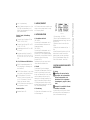
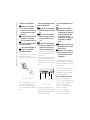
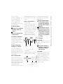
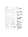
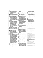
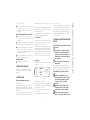
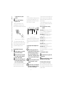
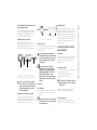
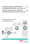
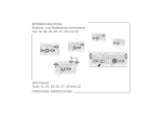
BETRIEBSANLEITUNG
Flaschendruckminderer Baureihe 300
FMD 302-14
FMD 300-18
FMD 302-18
FMD 300-14
Cylinder Pressure Regulator Series 300
OPERATING INSTRUCTIONS
1.1 Vorbemerkung
Diese Armaturen sind Präzisionsinstrumente von
höchster Qualität. Durch die Verwendung ausgewählter Materialien, durch hohe Oberflächengüte und Dichtheit lassen sich Druck und
Durchfluß auch von reinsten Gasen ohne Verfälschung der Reinheit präzise mit gleichbleibender
Genauigkeit regeln. Alle Schritte - von der Konzeption über die Fertigung bis zur Endkontrolle unterliegen den strengen Kriterien unserer
Qualitätssicherung.
1.2 Bestimmungsgemäße Verwendung
Die Flaschendruckminderer der Baureihe
300 zeichnen sich durch hohe Betriebssicherheit,
ausgereifte Technik und vielfältige Einsatzmöglichkeiten aus. Ausschließlich
in Messing gefertigt eignen sich diese
Armaturen für inerte, brennbare und brennfördernde
Gase und Gasgemische bis Reinheitsklasse 5.0. Sie
sind für den direkten Anschluß an Gasflaschen zur
Reduzierung des Flaschendruckes von maximal 200
bar auf niedrigere Ausgangsdruckbereiche vorgesehen. Die zweistufige Ausführung FMD 302
sichert konstanten Hinterdruck unabhängig von der
Änderung des Vordruckes. Der zulässige
Temperatureinsatzbereich reicht von -20°C bis
+70°C. Beachten Sie für eine bestimmungsgemäße
Verwendung neben der Bedienungsanleitung das
Typenschild, das Gasartschild sowie die zugehörigen
Datenblätter.
1.3 Gewährleistung und Haftung
Grundsätzlich gelten unsere ”Allgemeinen Verkaufs- und Lieferbedingungen”.
Gewährleistungs- und Haftungsansprüche bei
Personen- und Sachschäden sind ausgeschlossen,
wenn sie auf eine oder mehrere der folgenden
Ursachen zurückzuführen sind:
- Nicht bestimmungsgemäße Verwendung des
Druckgerätes.
- Unsachgemäßes Montieren, Inbetriebnehmen,
Bedienen und Warten des Druckgerätes.
- Betreiben des Druckgerätes bei defekten Sicherheitseinrichtungen oder nicht ordnungsgemäß
angebrachten oder nicht funktionsfähigen
Sicherheits- und Schutzvorrichtungen.
- Nichtbeachten der Hinweise in der Bedienungsanleitung bezüglich Transport, Lagerung, Montage,
Inbetriebnahme, Betrieb, Wartung und Rüsten des
Druckgerätes.
- Eigenmächtige bauliche Veränderungen an dem
Druckgerät.
- Mangelhafte Überwachung von Ausrüstungs-,
Verschraubungs- und Dichtungsteilen, die einem
Verschleiß unterliegen.
- Unsachgemäß durchgeführte Reparaturen.
- Katastrophenfälle durch Fremdkörpereinwirkung
und höhere Gewalt.
Personen. Nichtbeachten dieser Hinweise hat
schwere gesundheitsschädliche Auswirkungen zur
Folge, bis hin zu lebensgefährlichen Verletzungen.
Dieses Symbol bedeutet eine möglicherweise
drohende Gefahr für das Leben und die Gesundheit von Personen. Nichtbeachten dieser Hinweise
kann schwere gesundheitsschädliche Auswirkungen zur Folge haben, bis hin zu lebensgefährlichen
Verletzungen.
Dieses Symbol bedeutet eine möglicherweise
gefährliche Situation. Das Nichtbeachten
dieser Hinweise kann leichte Verletzungen zur
Folge haben oder zu Sachbeschädigungen führen.
Dieses Symbol gibt wichtige Hinweise für den
sachgerechten Umgang mit dem Druckgerät. Das
Nichtbeachten dieser Hinweise kann zu Störungen am Druckgerät oder in der Umgebung
führen.
Unter diesem Symbol erhalten Sie AnwendungsTips und besonders nützliche Informationen. Sie
helfen Ihnen, alle Funktionen an Ihrem Druckgerät
optimal zu nutzen.
1.4 Urheberrecht
Das Urheberrecht an dieser Bedienungsanleitung
verbleibt beim Hersteller. Diese Bedienungsanleitung ist nur für den Betreiber und dessen Personal
bestimmt.
2. GRUNDLEGENDE SICHERHEITSHINWEISE
2.1 Erläuterung der Hinweissymbole
In der Bedienungsanleitung werden folgende Benennungen und Zeichen für Gefährdungen verwendet:
Dieses Symbol bedeutet eine unmittelbar drohende Gefahr für das Leben und die Gesundheit von
-1-
2.2
Besondere Sicherheitshinweise
Durch den Umgang mit komprimierten
Gasen und den dazugehörigen Armaturen
können Gefahren für Leib und Leben des
Benutzers oder Dritter bzw. Beeinträchtigungen am Druckgerät oder an anderen
Sachwerten entstehen.
Vor jeder Inbetriebnahme des Druckgerätes müssen alle Sicherheitseinrichtungen sachgerecht angebracht und
funktionsfähig sein.
Betriebsanleitung FMD 300
1. GRUNDLEGENDE HINWEISE
Betriebsanleitung FMD 300
Schutzvorrichtungen und Sicherheitseinrichtungen dürfen nur entfernt werden
nach Außerbetriebsetzen des Druckgerätes bzw. der Anlage und nach Absicherung gegen Wiederinbetriebnahme
des Druckgerätes.
Bei geöffneten Sicherheitseinrichtungen
oder Störfällen können schädliche Gase
und Dämpfe entweichen .
Persönliche Schutzeinrichtungen sind
vom Betreiber beizustellen.
Bei Sauerstoffmangel oder zu hoher
Schadstoffkonzentration sind von der
Umgebungsatmosphäre unabhängige
Atemschutzgeräte erforderlich! (VBG 1).
Falls die Ventile nach Arbeitsende nicht
verschlossen werden, ist ein Gasaustritt
durch die Schläuche oder die
angeschlossenen Verbraucher möglich!
Das Schließen des Druckminderers
alleine garantiert keine absolute
Dichtheit.
Die Bedienungsanleitung ist ständig am
Einsatzort des Druckgerätes
aufzubewahren.
Die Bedienungsanleitung ist zu beachten.
Sie enthält wichtige Hinweise, um das
Druckgerät sicherheitsgerecht zu
betreiben.
Der Betreiber verpflichtet sich nur
Personen am Druckgerät arbeiten zu
lassen, die mit den grundlegenden
Vorschriften über Arbeitssicherheit und
Unfallverhütung vertraut sind, die in die
Handhabung des Druckgerätes
eingewiesen sind und das
Sicherheitskapitel und die Warnhinweise in dieser Bedienungsanleitung
gelesen und verstanden haben.
Das Personal muß sich vor
Inbetriebnahme der Armatur mit den
Gefahrenhinweisen für das verwendete
Gas vertraut machen.
Die Zuständigkeiten des Personals sind
klar festzulegen für das Montieren,
Inbetriebnehmen, Bedienen, Rüsten,
Warten und Instandsetzen.
Anzulernendes Personal darf nur unter
Aufsicht einer erfahrenen Person am
Druckgerät arbeiten.
Ergänzend zur Bedienungsanleitung sind
die allgemeingültigen sowie die örtlichen Regelungen zur Unfallverhütung
und zum Umweltschutz bereitzustellen
und zu beachten.
Das Druckgerät ist nur in sicherheitstechnisch einwandfreiem Zustand zu
benutzen.
Das Druckgerät ist nur für die bestimmungsgemäße Verwendung (siehe
Typenschild, Gasartschild und Datenblatt) zu benutzen.
Die zugehörigen Datenblätter sind hinsichtlich der Betriebsbedingungen beachten.
Alle Sicherheits- und Gefahrenhinweise
am Druckgerät sind in lesbarem Zustand
zu halten.
Alle mit Sauerstoff in Berührung kom-2-
menden Teile müssen absolut öl- und
fettfrei sein, Brand- und Explosionsgefahr!
Nur Schmierstoffe mit Sauerstoffzulassung verwenden!
Das Wechseln der Flaschenanschlußteile oder die Verwendung von Übergangsstücken für unterschiedliche Anschlüsse nach DIN 477 ist untersagt
(Geräteschutzgesetz)!
Verwendete, zur Reparatur anstehende
Gasgeräte mit einem inerten Gas (Stickstoff, Argon) spülen und feste Gasrückstände sachgerecht handhaben und
entsorgen, insbesondere nicht durch
Schmierstoffe bzw. ölige Lappen die
Verschraubungsteile verunreinigen und
nicht mit Lösungsmitteln reinigen.
Vorgeschriebene Einstell-, Wartungsund Inspektionsarbeiten fristgemäß
durchführen lassen.
2.3 Gesetze, Normen, Vorschriften und
Hinweise
Gesetze und Verordnungen
“Gerätesicherheitsgesetz GSG” mit
"aVV allgemeinen Verwaltungsvorschriften“,
6. GSGV Druckbehälterverordnung” und
“7. GSGV Gasverbrauchseinrichtungsverordnung”,
”ChemG Chemikaliengesetz” mit
“GefstoffV Gefahrenstoffverordnung” und
“ArbstoffV-Arbeitstoffverordnung”.
Alle Teile müssen sauber verpackt, staubfrei, trocken
und gut verschlossen gelagert werden. Nur sachgerechte Verpackung benützen.
Technische Regeln, Unfallverhütungsvorschriften:
“Technische Regeln Druckbehälter TRB” mit
TRB 610, 700, 801/26, 801/27.
“Technische Regeln Druckgase TRG” mit TRG
100, 101, 102, 250, 280.
“Unfallverhütungsvorschriften VBG” mit VBG 1,
15, 61 und 62.
“Berufsgenossenschaftliche Richtlinien ZH 1”
mit ZH 1/8, 1/8.1, 1/8.2, 1/8.3, 1/10, 1/16, 1 /
119, 1/134, 1/180, 1/288, 1/307, 1/382, 1/384,
1/605.
DIN-, ISO-, CEN-Normen und VDE-Richtlinien:
DIN 8545 (Hauptstellendruckminderer), DIN
2403 (Kennzeichnung für Rohrleitungen nach
dem Durchflußstoff).
ISO 2503 (Pressure Regulators for gas cylinders
used in welding, cutting and allied processes).
EN 585 (Druckminderer für Gasflaschen,
Schweißen, Schneiden und Verwandte Verfahren), EN 562 (Manometer für Schweißen,
Schneiden und verwandte Verfahren).
VDE 0170 (Errichten elektrischer Anlagen in explosionsgefährdeten Bereichen).
Informationsschriften:
Datenblätter Baureihe 300.
4. DATEN DER ARMATUREN
4.1 Druckminderer und Ventile
FMD 300/302-14:
Ein-/zweistufiger Flaschendruckminderer mit Vorund Hinterdruckmanometer, Abblaseventil und
Klemmringverschraubung.
FMD 300/302-18:
Ein-/zweistufiger Flaschendruckminderer mit Vorund Hinterdruckmanometer, Abblaseventil und
Dosierventil SVR 300 und Ausgangsverschraubung.
Flaschenanschluß (je nach gewünschter Gasart) und
Flammensperre (optional) sind beigefügt.
Dosierventil SVR 300:
Stopfbuchsventil aus Messing vernickelt und verchromt in Winkelform. Nenndruck 40 bar.
4.2 Zubehör
Für die Baureihe 300 sind Verschraubungen,
Schlauchtüllen und Flammensperren lieferbar. Bitte
wenden Sie sich diesbezüglich an den Hersteller.
Montage- und Einbauvorschriften für diese Komponenten sind unbedingt zu befolgen. Achten Sie
unbedingt auf die Verwendung einwandfreier Dichtungen, auf einwandfreien Zustand aller Gewinde,
auf Dichtheit und einwandfreie Funktion im fertigmontierten Zustand. Bitte beachten Sie auch Punkt 5.
und 6. dieser Bedienungsanleitung.
4.3 Kennzeichnung
Die Typenschilder der Druckminderer weisen folgende Kennzeichnungen aus:
-3-
Typenschild
1. Typkennzeichnung (... FMD 300-14).
2. Werkstoffe des Druckminderergehäuses und der
Sitzdichtung des Druckminderers und ggf. des Ventils
(Ms/PVDF/PCTFE).
3. Zugelassener Vordruck für dieses Gerät (Pein: ...
200 bar).
4. Gerätespezifischer Hinterdruckbereich (Paus: ... 1 6 bar).
Auf dem Flaschenanschluß befindet sich ein Schild
mit dem Hinweis für welche Gasart der Druckminderer geeignet ist und eine eingeschlagene
Ziffer, die die Anschlußnummer festlegt (siehe
Tabelle “Gasflaschenventile” weiter unten).
5. MONTAGE, ANSCHLIESSEN UND ERSTE
INBETRIEBNAHME
5.1 Montage
Kontrollieren Sie zuerst an Hand des
Typenschildes und des Gasartschildes
auf dem Flaschenanschluß, ob der
Druckminderer für den vorgesehenen
Verwendungszweck geeignet ist (Gasart,
Druck).
Verwenden Sie ausschließlich Flaschenanschlüsse des Herstellers.
Vor dem Anschließen an die Gasflasche sind zuerst
der Flaschenanschluß und die Flammensperre (nur
Option) am Druckminderer zu befestigen.
Betriebsanleitung FMD 300
3. LAGERUNG, TRANSPORT
“BImSchG Immissionsschutzgesetz” mit “BImSchV FCKW-Halon-Verbotsordnung” und “2.
BImSchV Emissionsbegrenzung von leichtflüchtigen Kohlenwasserstoffen”.
Hersteller
“AcetV Acetylenverordnung”.
Betriebsanleitung FMD 300
5.1.1 Montage des Flaschenanschlusses
Keinesfalls darf der Druckminderer
durch Austausch des Flaschenanschlusses für eine andere Gasart eingesetzt werden. Gefahr von chemischen
Reaktionen!
Achten Sie darauf, daß die Gewinde am
Druckminderer und am Flaschenanschluß in einwandfreiem Zustand sind.
Achten Sie auf einwandfreien Zustand
und Sitz des O-Ringes (4)
in der Nut des Flaschenanschlusses (3).
Benützen Sie nur Original-Ersatzdichtungen des Herstellers.
1. Fügen Sie den Flaschenanschluß (1) in die vorgesehene Bohrung an der Rückseite des
Druckminderers (5) und drehen Sie ihn mit der Hand
fest.
5.1.2 Montage der Flammensperre (lieferbares
Zubehör) am FMD 300/302-14/18:
Verwenden Sie aus Sicherheitsgründen
ausschließlich Originalteile des Herstellers.
Achten Sie sowohl auf einwandfreien
Zustand von Dichtungen und Gewinden
als auch auf einwandfreien Sitz aller
Teile.
Verwenden Sie bei der Montage neue
Dichtungen. Die Dichtungen dürfen nicht
deformiert sein und keine Spuren von
Schmutz oder Metallspänen aufweisen.
1. Herausschrauben der am Druckminderer vorhandenen Standard-Klemmringringverschraubung (4) mit
Gabelschlüssel (SW 19).
2. Einschrauben der Flammensperre (2) zusammen
mit der Dichtung (1) in das Innengewinde G 1/4" am
Druckmindererausgang von Hand. Festziehen mit einem Gabelschlüssel (SW 22) um 3/8 bis 1/2 Umdrehung.
Dichtring (3)
Montage Flaschenanschluss / FMD 300/302
Flammensperre (2)
Dichtring (1)
2. Nehmen Sie einen Gabelschlüssel (SW 14) und
ziehen Sie den Flaschenanschluß (1) an der
Schlüsselfläche (2) des Verbindungsrohrstückes fest.
Für eine feste Montage genügt das Gegenhalten mit
der Hand.
Klemmringverschraubung
(4)
Montage der Flammensperre
3. Dichtung (3) in das Innengewinde der Flammensperre (2) einlegen. Adapter (4) zunächst von Hand einschrauben und dann mit einem Gabelschlüssel (SW 19)
um 3/8 bis 1/2 Umdrehung festziehen.
-4-
5.2 Anschließen des Druckminderers an die
Flasche.
Stellen Sie sicher, daß die Gasartbezeichnung auf dem Gasartschild des
Flaschenanschlusses mit der Gasart auf
der Gasflasche übereinstimmt. Siehe
auch die Tabelle weiter unten
“Gasflaschenventile” mit Gasarteignung,
Anschlußnummer und zugehörigem
Gewinde.
Das Gewinde am Flaschenventil und an
der Überwurfmutter müssen in einwandfreiem Zustand sein.
Verwenden Sie bei jeder Montage einwandfreie Dichtungen: ohne Spuren von
Schmutz oder Metallspänen und ohne
Beschädigungen.
1. Die Überwurfmutter auf den Ventilanschluß auf
der Flasche aufschrauben. Auf Rechts- und Linksgewinde achten! Den Druckminderer ausrichten. Beim
Ansetzen nicht verkanten.
2. Aufschrauben und von Hand festziehen. Keine
Werkzeuge wie Zangen verwenden. Das Festziehen
der gerändelten Mutter mit der Hand genügt, um
ausreichende Dichtheit zu erreichen.
Tabelle: Gasflaschenventile nach DIN 477.
Anschluß Nr. 1, Seitenstutzengewinde
W 21,80 x 1/14” links: für brennbare (leicht entzündliche) Gase und Gasgemische nach Tabelle 2 und 3.
Anschluß Nr. 2, Seitenstutzengewinde
W 21,80 X 1/14”: für unbrennbare oder schwer
entzündliche Gase nach Tabelle 3.
Anschluß Nr. 9, Seitenstutzengewinde
R 3/4”: für Sauerstoff und synthetische Luft.
Anschluß Nr. 10, Seitenstutzengewinde
5.3 Anschließen der Verbraucher
Verwenden Sie aus Sicherheitsgründen
ausschließlich Originalteile des
Herstellers.
Achten Sie auf einwandfreien Zustand
und Sitz der Gewinde.
Standard-Klemmringverschraubung. Anschließen des
Rohres (2) zum Verbraucher wie unter Punkt 5.31
beschrieben.
Montage von Einsteck-Schlauchtüllen
1. Montage des Adapters
Einführen des Schlauchtüllen-Einsteck-Adapters (1)
in die am Druckminderer vorhandene StandardKlemmringverschraubung. Dann die Überwurfmutter
mit einem Gabelschlüssel (SW 12) festziehen bis die
Mutter das Anschlußgewinde überdeckt und Gegenhalten mit einem Gabelschlüssel (SW 19) an der
Schlüsselfläche der Standard-Klemmringverschraubung. Anschließen des Rohres (2) zum
Verbraucher wie unter Punkt 5.31 beschrieben.
schieben und anschließend auf den Adapter (1) schieben. Schlauchbinder (2) festziehen, um Schlauch (3)
gegen Abziehen zu sichern.
Bei Helium und Wasserstoff empfiehlt
sich die Verwendung von Schläuchen
mit besonders kleinen Diffusionsleckraten (bei Fragen wenden Sie sich bitte an
den Hersteller).
Alle Verbindungen müssen nach Montage mit einem Prüfspray auf Dichtheit
geprüft werden. Verwenden Sie nur ein
Prüfspray mit DVGW- Zulassung (DVGW
= Dt. Fachverband für Gas und Wasser).
Beachten Sie die Bedienungsanleitung
des Prüfsprays.
5.3.1 Anschließen von 6 mm-Rohrleitungen.
Einführen der Rohrleitung in die Klemmringverschraubung. Festziehen der Überwurfmutter mit 1
1/4 Umdrehungen und Gegenhalten an der
Schlüsselfläche des Adapters. Auf einwandfreie
Dichtheit achten.
5.3.2 Montage von Einsteck-ReduzierVerschraubungen oder Einstecktüllen
Für den Anschluß von Verbrauchern an den
Druckminderer stehen (neben der mitgelieferten
6mm-Klemmringverschraubung) zahlreiche weitere
Klemmringverschraubungen und Schlauchtüllen als
Einstecker zur Verfügung.
5.4
Rohr (3)
Rohrstutzen (1)
Standardklemmringverschraubung (2)
Reduzieradapter
Montage eines
Reduzieradapters
2. Schlauchmontage
Handelsüblichen Schlauchbinder (2) (nicht im Lieferumfang der Schlauchtülle) über das Schlauchende (3)
Montage von Klemmring-Einsteckern
Einführen des Stutzens des Klemmring-EinsteckAdapters (1) in die am Druckminderer vorhandene
Standard-Klemmringverschraubung. Dann die Überwurfmutter mit einem Gabelschlüssel (SW 12) festziehen bis die Mutter das Anschlußgewinde überdeckt und Gegenhalten mit einem
Gabelschlüssel (SW 19) an der Schlüsselfläche der
Schlauchtülle(1)
Schlauch (3)
Montage von Schlauchbindern
-5-
Schlauchbinder
(2)
Inbetriebnahme
5.4.1 Vorbereitung
Handrad des Druckminderers bis zum Anschlag nach
links drehen - Durchgang ist damit geschlossen. Alle
Ventile schließen.
Vor Einschalten des Druckgerätes ist
sicherzustellen, daß niemand durch das
Inbetriebnehmen des Druckgerätes
gefährdet werden kann.
5.4.2 Gasentnahme
Stellen Sie sich neben die Armatur (nicht in Front
zu den Bedienelementen) und öffnen Sie langsam
das Flaschenventil. Vordruckmanometer beachten.
Gewünschten Ausgangsdruck mit dem Druckmindererhandrad - durch langsame Rechtsdrehung
- einstellen. Gewünschte Durchflußmenge am
Dosierventil bzw. am Ventil des nachgeschalteten
Gasverbrauchers einstellen.
Betriebsanleitung FMD 300
W 24,32 x 1/14”: für Stickstoff.
Anschluß Nr. 11, Seitenstutzengewinde R 3/8”: für
Distickstoffoxid (Stickoxydul, Lachgas).
Anschluß Nr. 14, Seitenstutzengewinde
M 19x1,5: für nichtkorrosive Prüfgase.
Bei Verwendung anderer Flaschenventile wenden
Sie sich bitte an den Hersteller.
Betriebsanleitung FMD 300
6. BETRIEB, FLASCHENWECHSEL UND
AUSSERBETRIEBNAHME
7. WARTUNG UND INSTANDHALTUNG
8. HERSTELLER / DRUCKLEGUNG
7.1 Wartung
Technische Änderungen, die dem Fortschritt dienen,
sind vorbehalten. © beim Hersteller, siehe
Rückseite.
Printed in Germany. Gedruckt auf chlorfrei
gebleichtem Papier / bd. Ausgabe 2/08/00,
ba300ges.
6.1 Betrieb
Alle mit Sauerstoff in Berührung kommenden Teile müssen absolut öl- und
fettfrei sein.
Während des Betriebes erfolgt die Änderung des
gewünschten Hinterdruckes durch Drehung des
Handrades im Uhrzeigersinn (Vergrößerung) oder
gegen den Uhrzeigersinn (Verringerung des Ausgangsdruckes).
6.2
Wechseln der Flaschenanschlußteile
oder die Verwendung von Übergangsstücken für unterschiedliche Anschlüsse
nach DIN 477 ist untersagt.
Flaschenwechsel
1. Absperrventil an der Gasflasche (am Druckgasbehälter) fest schließen.
2. Druckregler und Leitungen durch Ableiten des
Gases über den Verbraucher entspannen.
Zeiger von Vor- und Hinterdruckmanometer müssen vollständig auf “0”
zurückgegangen sein.
3. Überwurfmutter an der Gasflasche lösen.
4. Neue Flasche wie oben beschrieben anschließen.
6.3 Außerbetriebnahme
Bei kurzzeitiger Unterbrechung der Gasentnahme
genügt das Schließen des Brauchgasausgangsventils. Bei längerer Unterbrechung muß der Druckminderer durch Drehung des Handrades entgegen
dem Uhrzeiger entspannt werden. Andernfalls droht
vollständiger Verlust des gesamten Gasevorrates.
Aus Sicherheitsgründen bei Außerbetriebnahme das Flaschenventil
schließen.
Reparaturen und Wartungen sind aus
Sicherheitsgründen nur vom Hersteller
oder durch vom Hersteller autorisierte
Fachbetriebe ausschließlich mit
Originalersatzteilen des Herstellers
durchzuführen.
Um einwandfreie Funktion und gleichbleibende
Betriebssicherheit der Armaturen sicherzustellen,
sollen alle Komponenten einer Gasversorgung
jährlich einmal vom Hersteller überprüft werden. Es
empfiehlt sich hierfür der Abschluß eines Wartungsvertrages. Beachten Sie die Garantie- und Lieferbedingungen des Herstellers.
7.2
Betriebsstörungen
Diese Druckminderer arbeiten stets zuverlässig.
Sollte dennoch kein bestimmungsgemäßer Betrieb
der Armatur möglich sein (z. B. unzulässiger Hinterdruckanstieg), so setzen Sie sich bitte mit dem
Hersteller in Verbindung.
-6-
1.1 Preliminary Remark
These armatures are precision instruments of the
highest quality. The use of selected materials, high
surface quality and sealing allows the pressure and
flow rate of even the purest gases to be regulated
precisely and with constant accuracy without
distorting the purity. All steps – from conception to
finish to pre-delivery inspection – are subject to
strict quality assurance criterias according to DIN
EN ISO 9001.
1.2 Proper Use
The series 300 pressure regulators for cylinders is
characterized by high operational safety, advanced
technology and diverse application options. These
armatures, made solely of brass, are suitable for
inert, combustible and combustive gases and gas
mixtures up to purity class 5.0. They are designed
for direct attachment to gas cylinders to reduce the
cylinder pressure from maximum 200 bars to a
lower outlet pressure range. The twin-stage
execution of the AMD 302 guarantees constant
back pressure independent of the change in the
admission pressure. The permissible temperature
application range extends from -20C to +70C. In
addition to the operating instructions, please take
note of the data plate, the gase-type plate as well
as the relevant data sheets to ensure proper use.
1.3 Warranty and Liability
Our ”General Sales and Delivery Conditions” are
fundamentally valid. Warranty and liability claims for
personal or product damage are invalid if they can be
traced to one or more of the following causes:
- Incorrect use of the pressure device
-
Incorrect assembly, start-up, operation and
maintenance of the pressure device
-
Operation of the pressure device in cases of
defective safety devices, or when safety and
protection fixtures are incorrectly attached or
not in proper working order.
-
Non-observance of the instructions in the
operating manual regarding transport, storage, assembly, start-up, operation, maintenance and preparation of the pressure device.
-
Unauthorized structural changes to the pressure device.
-
Insufficient testing of equipment, connection
and sealing parts that are subject to wear
and tear
-
Repairs carried out incorrectly
-
Disaster situations arising from third party/
foreign body interference and Acts of God.
1.4 Copyright
The copyright for these operating instructions
remains with the manufacturer. These operating
instructions are intended only for the operating
company and its employees.
2. BASIC SAFETY INSTRUCTIONS
2.1 Explanation of Safety Symbols
This symbol signifies potential danger that is
life-threatening or poses a threat to the health
of employees. Failure to observe these
instructions can lead to serious or even lifethreatening injuries.
This symbol signifies a potentially dangerous
situation. Failure to observe these instructions
can lead to minor injuries or property damage.
This symbol points out important instructions
on how to handle the pressure device
correctly. Failure to observe these instructions
can cause the device to malfunction or lead to
disturbance in the surroundings.
This symbol points out application tips and
particularly useful information. It helps you
optimally utilize all of the functions of your
pressure device.
2.2 Special Safety Instructions
Handling compressed gases and the
respective armatures can result in
serious injury to the user or third party
or damage to the pressure device or
other property.
The following descriptions and characters are used
in the operating instructions to illustrate danger:
Before the pressure device is put into
operation, all safety devices must be
correctly attached and in working order.
This symbol signifies immediate danger that
is life-threatening or poses a threat to the
health of employees. Failure to observe
these instructions can lead to serious or
even life-threatening injuries.
Protection fixtures and safety devices
may only be removed when the pressure
device or the system are not operational
and after safety precautions have been
taken to prevent renewed operation of
the pressure device.
-7-
Operating Instructions FMD 300
1. BASIC INSTRUCTIONS
Operating Instructions FMD 300
Hazardous gases and steam can escape
if the safety devices are open or
malfunctions occur.
The user must be provided with personal
protective equipment.
Respiratory equipment independent of
the surrounding atmosphere is required
in the event of an oxygen shortage or
extremely high concentrations of harmful
substances,.
If the valves are not closed following
completion of work, gas may escape
through the hoses or the connected
consumer! Closing the pressure
regulators does not guarantee that no
leaks will occur.
employed gas.
by DIN 477 (Device Protection Law).
Employee responsibilities must be
clearly established regarding assembly,
start-up, operation, preparation,
maintenance and repairs.
Always flush used gas devices awaiting
repairs with an inert gas (nitrogen,
argon) and handle and dispose of gas
residues properly. Ensure that the
connecting parts are not contaminated
by using lubricants or oily cloths and do
not clean with solvent.
Employees in training may only work
with the pressure device under the
supervision of an experienced person.
In addition to the operating instructions,
generally applicable and local
regulations for accident prevention and
environmental protection must be
provided and observed.
The pressure device may only be used if
it is in perfect working condition and
operationally safe.
The operating instructions must always
be kept in the place where the pressure
device is operated.
The pressure device may only be used
for the intended application (see data
plate, gas-type plate and data sheet).
The operating instructions must be
observed! They contain important
instructions for the safe operation of the
pressure device.
The appropriate data sheets must be
observed with regard to the operating
conditions.
The user is obligated to allow only those
employees to work with the pressure
device who are familiar with the fundamental work safety and accident
prevention regulations, who have been
instructed how to operate the pressure
device, and who have read and
understood the safety chapter and the
safety instructions in this operating
manual.
Before starting up the armature,
employees must familiarize themselves
with the safety instructions for the
All safety and danger decals on the
pressure device must be kept in good,
legible condition.
All parts that come into contact with
oxygen must be kept absolutely free of
oil and grease – danger of fire and
explosion.
Only use lubricants that are oxygenapproved.
It is prohibited to change the connecting
parts of the cylinder or to use temporary
parts for various connections as defined
-8-
Have the prescribed adjustment,
maintenance and inspection work
carried out within the specified time.
2.3 Laws, Standards, Regulations and
Instructions
Laws and Decrees:
”Device Safety Law GSG” with general administrative regulations aVV,
”Pressure Container Decree 6. GSGV” and ”Gas
Consumer Facilities Decree 7. GSGV”.
”Chemicals Law ChemG” with ”Noxious Substances Decree GefstoffV” and ”Work Substances Decree ArbstoffV”.
”Acetylene Decree AcetV”.
”Law for the Protection Against the Effects of
Noxious Substances BLMSchG” with ”FCKW
Halon Prohibition Order BlmSchV” and ”AntiPollution Limitation On Lightly Volatile Carbon
Hydrogen 2. BlmSchV”.
Technical Regulations, Accident Precaution
Regulations:
”Technical Regulations Pressure Container
TRB” with TRB610, 700,801/26/BOT/27.
”Technical Regulations Pressure Gas TRG” with
TRG 100, 101, 102, 250, 280.
”Accident Precaution Regulations VBG” with
EN 585 (pressure regulators for gas cylinders
used in welding, cutting and allied processes),
EN 56 (pressure gauges used in welding, cutting and allied processes).
VDE 0170 (constructing electrical facilities in
areas where explosions may occur).
Information Sheets:
Data sheets for the 300 series.
3. STORAGE AND TRANSPORT
All parts must be properly wrapped, sealed and
stored in a dust-free, dry place. Use only proper
packaging.
4. TECHNICAL DATA
4.1 Pressure Regulators and Valves
FMD 300-14/18
Single-stage pressure regulator for cylinders with
admission and back pressure gauges, relief valve
and metering valve SVR 300 (only with FMD 300-18).
FMD 302-14/18
Twin-stage pressure regulator for cylinders with
admission and back pressure gauges, relief valve
Cylinder connection (depending on desired type of
gas) and flame arrester (optional) are included.
Metering valve SVR 300:
Nickel-plated and chromium-plated angular brass
chevron valve. Nominal pressure 40 bars.
4.2 Accessories
Connections, hose nozzles and flame arresters are
available for the 300 series. Please contact the
manufacturer for more information.
The assembly and installation regulations for these
components must be adhered to. Ensure that the
seals and all threads are in perfect condition and
that the assembled product is completely sealed and
in good working conditions. Please take note of
Items 5. and 6. of these operating instructions.
4.3 Labelling
The label plates of the pressure regulator show the
following:
Type: FMD 300-14
Material:
brass/PVDF/PCTFE
Pin: 200 bars
Pout: 1-6 bars
Warning!
Parts under pressure.
Servicing by authorized
personnel only
He
Label plate
1. Product model (...FMD 300-14).
2. Material of pressure regulator casing and the
pressure regulator seat seal and, if applicable, of the
valve (Ms=brass/PVDF/PCTFE).
3. Permissible admission pressure for the device
(Pein: ....200 bars).
4. Back pressure values for the device
-9-
(Paus: 0,5 - 6 bars).
5. Date of maufacturing and a security information.
A plate on the cylinder connection indicates which
type of gas can be used with the pressure regulator.
An imprinted number on the plate stipulates the
connection number (see the table ”Gas Cylinder
Valves” chapter 5.2).
5. ASSEMBLY, CONNECTION AND INITIAL
START-UP
5.1 Assembling the cylinder connection and the
flame arrester
First check if the pressure regulator is
suitable for the planned application
(type of gas, pressure) according to the
product label and the gas-type plate on
the connection.
Use only cylinder connections of the
manufacturer.
The cylinder connection and the flame arrester
(optional) must be attached to the pressure regulator
before they are connected to the gas cylinder.
5.1.1 Assembling the cylinder connection
Under no circumstances may the
pressure regulator be used for another
type of gas by changing the cylinder
connection. Danger of chemical
reactions.
Make sure that the threads on the
pressure regulator and the cylinder
connection are in perfect condition.
Make sure that the O-ring (4) in the
groove of the cylinder connection (3) is
Operating Instructions FMD 300
ISO 2503 (pressure regulators for gas cylinders
used in welding, cutting and allied processes).
and metering valve SVR 300 (only with FMD 302-18).
Manufacturer
VBG 1, 15, 61 and 62.
”Professional/Trade Association Guidelines ZH
1” with ZH1/8, 1/8.1, 1/8.2, 1/8.3, 1/10, 1/16,
1/119, 1/134, 1/180, 1/288, 1/307, 1/382, 1/
384, 1/605.
DIN, ISO, CEN Standards and VDE Guidelines:
DIN 8545 (principle pressure regulators), DIN
2403 (label for pipe lines according to the flow
substance).
Operating Instructions FMD 300
in proper position and in perfect
condition.
Use only original manufacturer
replacement seals.
nescessary.
2. Screw the flame arrester (2) together with the seal
(1) into the back pressure female outlet G ¼" of the
pressure regulator by hand. Tighten with a spanner
(SW 22) by 3/8 to 1/2 of a rotation.
1. Insert the cylinder connection (1) in the
corresponding bore on the reverse side of the
pressure regulator (5) and tighten it with your hand.
Table: Gas Cylinder Valves According
to DIN 477
Seal (3)
Flame arrester (2)
Seal (1)
Tube fitting (4)
Mounting the flame arrestor
Mounting the flange connection to the FMD 300/302
2. Take a spanner with nominal width 14 mm
(spanner width at the joint) and tighten the flange
connection. Holding the connection in place with
your hand while tightening is sufficient.
5.1.2 Assembling the flame arrester
For safety purposes use only original
parts from the manufacturer.
Make sure that the seals and threads
are in perfect condition and that the
parts are inserted properly.
Use new seals for each assembly. The
seals may not be deformed or have any
traces of dirt or metal shavings.
1. Screw out the tube fitting (4) with a spanner (SW
19). Make sure that the seal (1) is in perfect
conditon. Replace the seal with a new one if
1. Screw the union nut to the valve connection of the
cylinder. Pay attention to the left and right threads!
Align the pressure regulator. Ensure that it does not
jam when attaching.
2. Screw and tighten using your hand. Do not use
tools such as pliers. Tightening the knurled nut with
your hand is sufficient.
3. Insert the seal (3) into the female outlet of the flame
arrester (2). Screw in the tube fitting (4) at first by hand.
Then tighten with a spanner (SW 19) by 3/8 to 1/2 of a
rotation.
5.2 Connecting the Pressure Regulator to the
Cylinder
Ensure that the gas-type label on the
gas-type plate of the cylinder connection
matches the type of gas on the gas cylinder. See also the table below ”Gas
Cylinder Valves” with gas-type characteristics, connection number and respective threads.
The thread on the cylinder valve and the
connection nut must be in perfect
condition.
Use perfect seals for each assembly. The
seals may not be deformed or have any
traces of dirt or metal shavings.
- 10 -
Connection No. 1, lateral screwneck W 21.80 x 1/
14” left: for combustible (easily flammable) gases
and gas mixtures according to table 2 & 3.
Connection No. 2, lateral screw neck W 21.80 x 1/
14”: for incombustible or inflammable gases
according to table 3.
Connection No. 9, lateral screw neck R 3/4”: for
oxygen and synthetic air.
Connection No. 10, lateral screw neck W24.32 x 1/
14”: for nitrogen.
Connection No. 11, lateral screw neck R3/8”: for
dinitrogen monoxide (laughing gas).
Connection No. 14, lateral screw neck M 19 x1.5:
for non-corrosive testing gases.
Please contact the maufacturer if you are using other
cylinder valves.
5.3 Connecting the consumers
For safety reasons use only parts of the
manufacturer.
Make sure that the threats are in perfect
condition and inserted properly.
5.3.1 Mounting the 6mm-consumer pipes
Insert the connecting pipe into the tube fitting.
Tighten the union nut with spanner (SW 12) until the
union nut completely covers the thread. Be careful to
get tight connections.
To connect consumers to the pressure regulators
there are several additional adapters (beside the
standard tube fitting 6mm) deliverable: tube fitting
reducers and hose nozzle tube adapters.
Assembling tube fitting reducers
5.4.2 Extracting Gas
Hose nozzle (1)
Hose (3)
Hose clamp (2)
Assembling hose nozzle tube adapters
Insert the connecting tube (1) of the tube fitting
adapter into the standard tube fitting of the
pressure regulator. Tighten the union nut (2) with a
spanner (SW 12) until the union nut completely
Mounting the hose
Push the hose (3) onto the hose nozzle (1) and attach
with a commercially approved hose clamp (2)
(available accessory).
When using helium and hydrogen, we
recommend that that you use hoses with
particularly small diffusion rates (if you
have any questions, please contact the
manufacturer).
Connection
tube (1)
Union nut (2)
Tube (3)
Tube fitting reducer
Assembling tube fitting reducers
covers the threat. To connect the tube (3) to the
consumer follow the instructions in chapter 5.3.1
Using a ¼” pipe: The original adapter
can be used with a ¼” pipe. Replace the
cutting ring, thrust collar and the union
nut. Replacement parts are available
from the manufacturer.
Assembling the hose nozzle tube adapter
Screw the hose nozzle tube adapter (1) into the
standard tube fitting of the pressure regulator.
Tighten the union nut with spanner (SW 12) until the
union nut completely covers the thread.
All connections must be tested for
tightness with a test spray following
assembly. Only use a test spray that is
DVGW-approved (DVGW = DI. Fachverband für Gas und Wasser - Trade
Association for Gas and Water Sealing).
Please take care of the test spray users
manual.
5.4 Start-Up
5.4.1 Preparation
Turn the hand wheel of the pressure regulator to the
left to the end position – this closes the passage.
Close all valves.
Before switching on the pressure device,
ensure that no one can be injured during
the start-up process.
- 11 -
Place yourself beside the armature (not in front of
the operating elements) and slowly open the cylinder
valve. Monitor the admission pressure gauge.
Regulate the desired outlet pressure with the hand
wheel of the pressure regulator by slowly turning it
to the right. Regulate the desired flow rate on the
metering valve or if applicable on the valve of the
connected consumer.
6. OPERATION, CHANGING CYLINDERS,
CEASING OPERATION
6.1 Operation
During operation, you can adjust the back pressure
as desired by turning the hand wheel clockwise
(increase) or counter-clockwise (decreasing the
outlet pressure).
6.2 Changing Cylinders
1. Close the stop valve on the gas cylinder tightly (on
the compressed gas container).
2. Relieve the pressure regulator and hoses by
diverting the gas via the consumer.
The pointers for the admission and back
pressure gauges must have completely
returned to ”0”.
3. Remove the union nut on the gas cylinder.
4. Connect a new cylinder as described above.
6.3 Ceasing Operation
To interrupt gas extraction for brief periods it is
sufficient to close the outlet valve for the operating
Operating Instructions FMD 300
5.3.2 Assembling of tube fitting reducers and
hose nozzle tube adapters
Operating Instructions FMD 300
gas. For a longer period of interruption, the pressure
regulator must be relieved by turning the hand wheel
to the left.
For safety reasons close the cylinder
valve.
7. WARRANTY AND MAINTENANCE
7.1 Warranty
All parts that come into contact with
oxygen must be kept absolutely free of
oil and grease.
It is prohibited to change the connecting
parts of the cylinder or to use temporary
parts for various connections as defined
by with DIN 477 (Device Protection Law).
7.2 Operating Malfunctions
These pressure regulators always function reliably.
If, however, it is not possible to operate the armature
correctly, i.e. improper increase of the back pressure,
please contact the manufacturer.
8. PRINTING INFORMATION
Copyright to the manufacturer. Improvements are
subject to alterations. Printed in Germany. Edition 2/
08/00, ba300ges. Printed on chloride free bleached
paper, bd.
9. SUPPLIER
Please follow the information on the adhesive label
mounted at the cover back page.
For safety reasons, repairs and
maintenance may only be carried out by the manufacturer or by a
specialized company that
is authorized by the manufacturer to do
repairs using only original replacement
parts from the manufacturer.
All components of a gas system should be inspected by
the manufacturer annually in order to guarantee that
all armatures remain in good working order and are
operationally safe. It is recommended that a maintenance contract be drawn up for this purpose. Please
take note of the guarantee and delivery conditions of
the manufacturer.
- 12 -
please insert adress of the manufacturer (see back cover)
stamps.
sufficient
put on
Please
Redelivery formular - pressure device
Device: . . . . . . . . . . . . . . . . . . . . . . . . . . . . . . . . . . . . . . . . . . . . . . . . . . . . . . . . . .
Type / Serial number: . . . . . . . . . . . . . . . . . . . . . . . . . . . . . . . . . . . . . . . . .
Kind of assembly: . . . . . . . . . . . . . . . . . . . . . . . . . . . . . . . . . . . . . . . . . . . . .
Operation mode: . . . . . . . . . . . . . . . . . . . . . . . . . . . . . . . . . . . . . . . . . . . . . . .
Date:. . . . . . . . . . . . . . . . . . . . . . . . . . . . . . . . . . . . . . . . . . . . . . . . . . . . . . . .. .. . .
Sign: . . . . . . . . . . . . . . . . . . . . . . . . . . . . . . . . . . . . . . . . . . . . . . . . . .. .. . . . . . . . .
This pressure device has been cleaned and purged with inert
gas; nevertheless it can not be excluded, that there are to be
found rests of these listed gases:
....................................................................
....................................................................
Sender
Name:
Company:
Street:
Postcode:
City:
Country:
Telefone:
Fax:
....................................................................
........................................................
........................................................
........................................................
.................................
........................................................
........................................................
............................
............................
Detailed information at the following adress:
Company: . . . . . . . . . . . . . . . . . . . . . . . . . . . . . . . . . . . . . . . . . . . . . . . . . ... . . . .
Name: . . . . . . . . . . . . . . . . . . . . . . . . . . . . . . . . . . . . . . . . . . . . . . . . . . . . . . . . . ...
Telefone: . . . . . . . . . . . . . . . . . . . . . . . . . . . . . . . . . . . . . . . . . . . . . . . . . . . . . . . .
Please write in block letters!
........................................................
........................................................
........................................................
........................................................
........................................................
frankieren
ausreichend
Bitte
Rücklieferungsschein
Druckgerät
Gerät / Anlagenteil: . . . . . . . . . . . . . . . . . . . . . . . . . . . . . . . . . . . . . . . . . . .
Typ / Seriennummer: . . . . . . . . . . . . . . . . . . . . . . . . . . . . . . . . . . . . . . . . . .
Einbauart: . . . . . . . . . . . . . . . . . . . . . . . . . . . . . . . . . . . . . . . . . . . . . . . . . . . . . . .
Betrieb:. . . . . . . . . . . . . . . . . . . . . . . . . . . . . . . . . . . . . . . . . . . . . . . . . . . . . . . . .
Datum:. . . . . . . . . . . . . . . . . . . . . . . . . . . . . . . . . . . . . . . . . . . . . . . . . . . . . . . . . .
Unterschrift:. . . . . . . . . . . . . . . . . . . . . . . . . . . . . . . . . . . . . . . . . . . . . . . . . . . .
Dieses Druckgerät / dieses Anlagenteil wurde von uns gereinigt und
mit Inertgas gespült; trotzdem ist nicht auszuschließen, daß noch
Reste folgender Gase vorhanden sind:
....................................................................
....................................................................
....................................................................
Absender:
Name:
Firma:
Straße:
........................................................
........................................................
........................................................
PLZ/Ort:
Telefon:
Fax:
........................................................
........................................................
........................................................
Nähere Auskünfte unter folgender Adresse:
Firma: . . . . . . . . . . . . . . . . . . . . . . . . . . . . . . . . . . . . . . . . . . . . . . . . . . . . . . . . . . .
Name:. . . . . . . . . . . . . . . . . . . . . . . . . . . . . . . . . . . . . . . . . . . . . . . . . . . . . . . . . . .
Telefon:. . . . . . . . . . . . . . . . . . . . . . . . . . . . . . . . . . . . . . . . . . . . . . . . . . . . . . . . .
Bitte vollständig in Druckschrift ausfüllen!