1
GB
Instructions for use and installation
IT
Istruzioni per l’uso e l’installazione
FR
Mode d’emploi et installation
DE
Bedienungsanleitung und Einrichtung
TR
Kullanım ve montaj talimatları
Cooker Hood
Cappa
Hotte de Cuisine
Dunstabzugshaube
Davlumbaz
FGB 906 IS AC
INDEX
EN
RECOMMENDATIONS AND SUGGESTIONS ..................................................................................................................... 3
CHARACTERISTICS ............................................................................................................................................................. 4
INSTALLATION...................................................................................................................................................................... 6
USE ...................................................................................................................................................................................... 10
MAINTENANCE ................................................................................................................................................................... 12
INDICE
IT
CONSIGLI E SUGGERIMENTI............................................................................................................................................ 14
CARATTERISTICHE............................................................................................................................................................ 15
INSTALLAZIONE ................................................................................................................................................................. 17
USO...................................................................................................................................................................................... 21
MANUTENZIONE ................................................................................................................................................................ 23
SOMMAIRE
FR
CONSEILS ET SUGGESTIONS.......................................................................................................................................... 25
CARACTERISTIQUES......................................................................................................................................................... 26
INSTALLATION.................................................................................................................................................................... 28
UTILISATION ....................................................................................................................................................................... 32
ENTRETIEN......................................................................................................................................................................... 34
INHALTSVERZEICHNIS
DE
EMPFEHLUNGEN UND HINWEISE ................................................................................................................................... 36
CHARAKTERISTIKEN ......................................................................................................................................................... 37
MONTAGE ........................................................................................................................................................................... 39
BEDIENUNG........................................................................................................................................................................ 43
WARTUNG........................................................................................................................................................................... 45
IÇERIKLER
TR
TAVSIYELER VE ÖNERILER.............................................................................................................................................. 47
ÖZELLIKLER........................................................................................................................................................................ 48
MONTAJ............................................................................................................................................................................... 50
KULLANIM ........................................................................................................................................................................... 54
BAKIM .................................................................................................................................................................................. 56
2
2
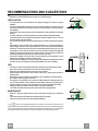
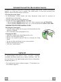
RECOMMENDATIONS AND SUGGESTIONS
The Instructions for Use apply to several versions of this appliance. Accordingly, you may find
descriptions of individual features that do not apply to your specific appliance.
INSTALLATION
• The manufacturer will not be held liable for any damages resulting from incorrect or improper
installation.
• The minimum safety distance between the cooker top and the extractor hood is 650 mm (some
models can be installed at a lower height, please refer to the paragraphs on working dimensions
and installation).
• Check that the mains voltage corresponds to that indicated on the rating plate fixed to the inside of
the hood.
• For Class I appliances, check that the domestic power supply guarantees adequate earthing.
Connect the extractor to the exhaust flue through a pipe of minimum diameter 120 mm. The route
of the flue must be as short as possible.
• Do not connect the extractor hood to exhaust ducts carrying combustion fumes (boilers, fireplaces,
etc.).
• If the extractor is used in conjunction with non-electrical appliances (e.g. gas burning appliances), a
sufficient degree of aeration must be guaranteed in the room in order to prevent the backflow of
exhaust gas. The kitchen must have an opening communicating directly with the open air in order
to guarantee the entry of clean air. When the cooker hood is used in conjunction with appliances
supplied with energy other than electric, the negative pressure in the room must not exceed 0,04
mbar to prevent fumes being drawn back into the room by the cooker hood.
• In the event of damage to the power cable, it must be replaced by the manufacturer or by the
technical service department, in order to prevent any risks.
• If the instructions for installation for the gas hob specify a greater distance specified above, this has
to be taken into account. Regulations concerning the discharge of air have to be fulfilled.
2°
USE
•
•
•
•
•
•
•
•
•
The extractor hood has been designed exclusively for domestic use to eliminate kitchen smells.
Never use the hood for purposes other than for which it has been designed.
Never leave high naked flames under the hood when it is in operation.
Adjust the flame intensity to direct it onto the bottom of the pan only, making sure that it does not
engulf the sides.
Deep fat fryers must be continuously monitored during use: overheated oil can burst into flames.
Do not flambè under the range hood; risk of fire
This appliance is not intended for use by persons (including children) with reduced physical, sensory or mental capabilities, or lack of experience and knowledge, unless they have been given supervision or instruction concerning use of the appliance by a person responsible for their safety.
Children should be supervised to ensure that they do not play with the appliance.
“ CAUTION: Accessible parts may become hot when used with cooking appliances.”.
MAINTENANCE
• Switch off or unplug the appliance from the mains supply before carrying out any maintenance
work.
• Clean and/or replace the Filters after the specified time period (Fire hazard).
• Clean the hood using a damp cloth and a neutral liquid detergent.
The symbol
on the product or on its packaging indicates that this product may not be treated as household waste. Instead it shall be handed over to the
applicable collection point for the recycling of electrical and electronic equipment. By ensuring this product is disposed of correctly, you will help prevent potential negative
consequences for the environment and human health, which could otherwise be caused by inappropriate waste handling of this product. For more detailed information
about recycling of this product, please contact your local city office, your household waste disposal service or the shop where you purchased the product.
EN
3
3
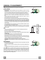
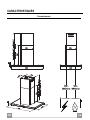
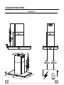
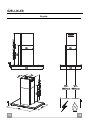
CHARACTERISTICS
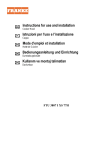
Dimensions
EN
4
4
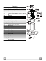
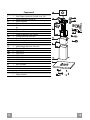
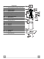
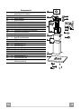
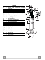
Components
Ref.
1
2
2.1
2.2
7.1
Q.ty
1
1
1
1
1
7.1a
7.1b
9
14.1
15
25
1
1
1
2
1
Ref.
7.3
11
12c
12e
12f
12g
12h
12q
21
22
23
Q.ty
1
4
6
2
2
4
4
4
1
8
4
Product Components
Hood Canopy complete with: Controls, Light, Filters
Telescopic chimney, made up of:
Upper chimney
Lower chimney
Telescopic frame complete with Suction fan, made up
of:
Upper frame
Lower frame
Reduction flange ø 150-120 mm
Air Outlet Connector Extension
Air Outlet Connector
Hose clamps (not supplied)
Installation Components
Air Outlet Connector fixing bracket
Wall plugs ø 10
Screws 2.9 x 6.5
Screws 2.9 x 9.5
Screws M4 x 80
Screws M6 x 80
Screws 5.2 x 70
Screws 3.5 x 9.5
Drilling template
Washers ø 6.4
Nuts M6
Q.ty Documentation
1 Instruction Manual
EN
5
5
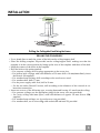
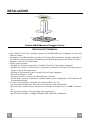
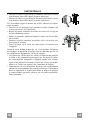
INSTALLATION
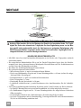
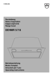
Drilling the Ceiling/shelf and fixing the frame
DRILLING THE CEILING/SHELF
• Use a plumb line to mark the centre of the hob on the ceiling/support shelf.
• Place the drilling template 21 provided on the ceiling/support shelf, making sure that the
template is in the correct position by lining up the axes of the template with those of the hob.
• Mark the centres of the holes in the template.
• Drill the holes at the points marked:
• For concrete ceilings, drill for plugs appropriate to the screw size.
• For hollow brick ceilings with wall thickness of 20 mm: drill ø 10 mm(immediately insert
the Dowels 11 supplied).
• For wooden beam ceilings, drill according to the wood screws used.
• For wooden shelf, drill ø 7 mm.
• For the power supply cable feed, drill ø 10 mm.
• For the air outlet (Ducted Version), drill according to the diameter of the external air exhaust duct connection.
• Insert two screws of the following type, crossing them and leaving 4-5 mm from the ceiling:
• For concrete ceilings, use the appropriate plugs for the screw size (not provided).
• for Cavity ceiling with inner space, with wall thickness of approx. 20 mm, Screws 12h,
supplied.
• For wooden beam ceilings, use 4 wood screws (not provided).
• For wooden shelf, use 4 screws 12g with washers 22 and nuts 23, provided.
EN
6
6
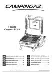
Fixing the frame
• Loosen the two screws fastening the lower chimney and remove this from the lower frame.
• Loosen the two screws fastening the upper chimney and remove this from the upper frame.
If you wish to adjust the height of the frame, proceed as follows:
• Unfasten the metric screws joining the two columns, located at
the sides of the frame.
• Adjust the frame to the height required, then refit all the screws
removed as above.
• Insert the upper chimney stack from above, and leave it running free on the frame.
• Lift up the frame, fit the frame slots onto the screws up to the
slot end positions.
• Tighten the two screws and fasten the other two screws provided with the hood.
Before tightening the screws completely it is possible to adjust
the frame by turning it. Make sure that the screws do not come
out of their seats in the slotted holes.
• The frame mountings must be secure to withstand the weight
of the hood and any stresses caused by the occasional side
thrust applied to the device.
On completion, check that the base is stable, even if the frame
is subjected to bending.
• In all cases where the ceiling is not strong enough at the suspension point, the installer must provide strengthening using
suitable plates and backing pieces anchored to the structurally
sound parts.
EN
1
2
1
2
7
7
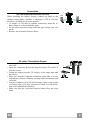
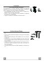
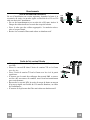
Connections
DUCTED VERSION AIR EXHAUST SYSTEM
When installing the ducted version, connect the hood to the
chimney using either a flexible or rigid pipe ø 150 or 120 mm,
the choice of which is left to the installer.
• To install a ø 120 mm air exhaust connection, insert the reducer flange 9 on the hood body outlet.
• Fix the pipe in position using sufficient pipe clamps (not supplied).
• Remove any activated charcoal filters.
ø 150
ø 120
25
9
25
Air outlet – Recirculation Version
• Insert the Connector extensions 14.1 into the side of the Connector 15.
• Insert the Connector 15 into the Support bracket 7.3 and fix it
with the screws.
• Fasten the Support bracket 7.3, fixing it to the upper part with
the Screws.
• Make sure that the Connector extensions outlet 14.1 is in correspondence with the Chimney openings both horizontally and
vertically.
• Join the Connector 15 to the Hood canopy outlet using a rigid
or flexible pipe ø¸150 mm, selection of which is at the discretion of the installation technician.
• Make sure that the Activated charcoal odour filter has been
fitted.
EN
12c
7.3
14.1
15
12e
7.3
8
8
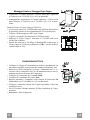
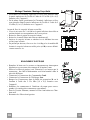
Flue assembly - Mounting the hood body
• Position the upper chimney section and fix the upper part to the
frame using the 2 screws 12c (2,9 x 6,5) provided.
• Similarly, position the lower chimney section and fix the
lower part to the frame using the 2 screws 12c (2,9 x 6,5) provided.
Before fixing the hood canopy to the frame:
• Screw the 2 screws 12f half way into the holes provided in the
sides of the bottom of the frame.
• Remove the grease filters from the hood canopy.
• Remove any activated charcoal filters.
• Lift the hood canopy and engage the screws 12f in the slots (A)
as far as they will go.
• Working from below, fix the hood canopy to the frame (B),
using the 4 screws 12q and 4 washers 22 provided, then tighten
all the screws securely.
ELECTRICAL CONNECTION
• Connect the hood to the mains through a two-pole switch having a contact gap of at least 3 mm.
• Remove the grease filters (see paragraph Maintenance) being
sure that the connector of the feeding cable is correctly inserted
in the socket placed on the side of the fan.
• Connect the control connector Cmd.
• Connect the lights connector Lux.
• Place the connectors in the junction box 24 and close it using
the 2 screws 12e (2,9 x 9,5) provided.
• Connect the connector inside the Hood respecting the colors.
• For the recirculation version, fit the activated carbon odour filter.
• Replace the grease filters.
EN
24
12e
Lux
12c
Cmd
9
9
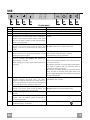
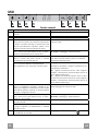
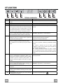
USE
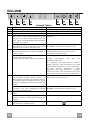
Control panel
Button
A
B
C
D
E
F
G
H
EN
Function
Turns the suction motor on and off at speed one.
Decreases the working speed.
Increases the working speed.
Activates Intensive speed from any other speed,
including motor off. This speed is set to operate for 6
minutes, after which the system returns to the speed
that was set before. Suitable to deal with maximum
levels of cooking fumes.
Press and hold the button for approximately 5
seconds, with all the loads turned off (Motor and
Lights), to turn the Activated Charcoal Filter alarm
on/off.
24H function
Turns the motor on at speed one and effects one 10
minute extraction every hour.
When the filters alarm is triggered, the alarm can be
reset by pressing and holding this button for
approximately 3 seconds.
These indications are only visible when the motor is
turned off.
Display
Displays the set speed
Displays the set speed
Displays the set speed
Displays HI and the time remaining alternately, once a
second.
FC+Dot (Flashes twice)-Alarm Activated.
FC+Dot (Flashes once)-Alarm Deactivated.
Displays 24 and the dot at the bottom right flashes
once a second, while the motor is running.
It is disabled by pressing the button.
FF flashes three times.
When the procedure terminates, the indication shown
previously turns off:
FG indicates the need to wash the metal grease filters.
The alarm is triggered after the Hood has been in
operation for 100 working hours.
FC indicates the need to change the activated charcoal
filters, and also to wash the metal grease filters. The
alarm is triggered after the Hood has been in operation
for 200 working hours.
Delay function
Displays the operating speed and the dot at the bottom
Activate automatic switch-off with a 30’ delay. right flashes once a second.
Suitable to complete elimination of residual odours. It
can be activated from any position and is deactivated
by pressing the button or turning the motor off.
Press and hold the button for approximately 5 IR+Dot (Flashes twice)-Alarm Activated.
seconds, with all the loads turned off (Motor and IR+Dot (Flashes once)-Alarm Deactivated.
Lights), to turn the Remote control on/off.
Turns the lighting system on and off at maximum intensity.
Press and hold the button for approximately 2 seconds, turns the lighting system on and off in
Courtesy Light mode.
Activates / Deactivates the Anti-condensation heating The corresponding symbol flashes.
elements(heating in 10 minutes).
1
10
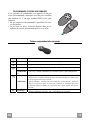
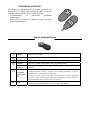
REMOTE CONTROL (OPTIONAL)
The appliance can be controlled using a remote control
powered by a 1.5 V carbon-zinc alkaline batteries of the
standard LR03-AAA type (not included).
• Do not place the remote control near to heat sources.
• Used batteries must be disposed of in the proper
manner.
Remote control panel
Motor
Motor On / Off.
Decreases the working speed each time it is pressed.
Increases the working speed each time it is pressed.
Intensive
Anticondensatio
n
24H/ Delay
Light
EN
Brief pressure: Activates/Deactivates the Intensive function
Long pressure: Activates/Deactivates the Anti-condensation heating
elements.
Brief pressure: Activates/Deactivates the Delay function: automatic switch-off
with a 30’ delay. The display shows the operating speed and the dot at the bottom
right flashes once a second.
Press and hold for 2 seconds to Activate/Deactivate the 24h function: this starts
the motor at speed one and allows suction for 10 minutes every hour. The display
shows the number 24 and the dot at the bottom right flashes once a second.
Brief pressure: Lights On / Off
Pressed for 2 Seconds: Courtesy lights On / Off
1
11
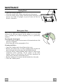
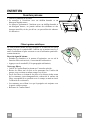
MAINTENANCE
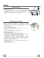
Opening Panel
• Open the Panel by pulling it.
• Clean the outside with a damp cloth and neutral detergent.
• Clean the inside using a damp cloth and neutral detergent; do
not use wet cloths or sponges, or jets of water; do not use
abrasive substances.
Metal grease filters
They can be washed in the dishwasher, and need to be cleaned
whenever the FG sign appears on the display or at least once
every 2 months use, or more frequently if use is particularly
intensive.
Resetting the alarm signal
• Turn the Lights and the Suction motor off, then disable the 24h
function, if enabled.
• Press button E (see the paragraph on Use).
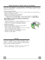
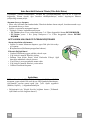
Cleaning the Filters
• Open the Comfort panels by pulling on the recess.
• Remove the Filters one at a time, pushing them towards the
back of the unit and at the same time pulling downward.
• Wash the Filters without bending them, and leave them to dry
completely before replacing. (If the surface of the filter
changes colour as time goes by, this will have absolutely no
effect on the efficiency of the filter itself.)
• Replace, taking care to ensure that the handle faces forwards.
• Close the Comfort panels.
EN
1
12
Activated Charcoal Filter (Recirculation Version)
It cannot be washed or regenerated, and must be changed when the FC symbol on the display
appears, or at least once every 4 months. The Alarm signal, if it has been activated, only
appears when the Suction motor is turned on.
Activating the alarm signal
• In Recirculation Version Hoods, the Filter Saturation Alarm must be activated on
installation or at a later date.
• Turn the Lights and the Suction Motor off.
• Press D and hold for approximately 5 Seconds:
• The message FC+Puntino flashes twice, A.C. Filter saturation alarm ACTIVATED
• The message FC+Puntino flashes once, A.C. Filter saturation alarm DEACTIVATED
CHANGING THE ACTIVATED CHARCOAL FILTER
Resetting the alarm signal
• Turn the Lights and the Suction motor off, then disable the 24h
function, if enabled.
• Press button E (see the paragraph on Use).
Changing the Filter
• Open the Comfort panels by pulling on the recess.
• Remove the Metal grease filters.
• Remove the saturated charcoal filter by releasing the fixing
hooks.
• Fit the new filter and fasten it in its correct position.
• Replace the Metal grease filters.
• Close the Comfort panels.
Lighting unit
Warning: This appliance is fitted with a white LED lamp classed
as 1M according to EN 60825-1: 1994 + A1:2002 + A2:2001
standards; maximum optical power emitted @439nm: 7µW. Do
not look directly at the light through optical devices (binoculars,
magnifying glasses…).
• For replacement contact technical support. ("To purchase contact technical support")
EN
1
13
CONSIGLI E SUGGERIMENTI
Questo libretto di istruzioni per l'uso è previsto per più versioni dell' apparecchio. É possibile che siano
descritti singoli particolari della dotazione, che non riguardano il Vostro apparecchio.
INSTALLAZIONE
• Il produttore declina qualsiasi responsabilità per danni dovuti ad installazione non corretta o non conforme
alle regole dell’arte.
• La distanza minima di sicurezza tra il Piano di cottura e la Cappa deve essere di 650 mm, (alcuni modelli
possono essere installati ad un’altezza inferiore, fare riferimento ai paragrafi ingombro e installazione).
• Verificare che la tensione di rete corrisponda a quella riportata nella targhetta posta all’interno della Cappa.
• Per Apparecchi in Classe Ia accertarsi che l’impianto elettrico domestico garantisca un corretto scarico a
terra.
• Collegare la Cappa all’uscita dell’aria aspirata con tubazione di diametro pari o superiore a 120 mm. Il
percorso della tubazione deve essere il più breve possibile.
• Non collegare la Cappa a condotti di scarico dei fumi prodotti da combustione (caldaie, caminetti, ecc.).
• Nel caso in cui nella stanza vengano utilizzati sia la Cappa che apparecchi non azionati da energia elettrica
(ad esempio apparecchi utilizzatori di gas), si deve provvedere ad una aerazione sufficiente dell’ambiente.
Se la cucina ne fosse sprovvista, praticare un’apertura che comunichi con l’esterno, per garantire il richiamo d’aria pulita. Un uso proprio e senza rischi si ottiene quando la depressione massima del locale non
supera i 0,04 mBar.
• In caso di danneggiamento del cavo alimentazione, esso deve essere sostituito dal costruttore o dal servizio di assistenza tecnica, in modo da prevenire ogni rischio.
• Se le istruzioni di installazione del dispositivo di cottura a gas indicano che è necessaria una distanza
maggiore di quella indicato sopra, è necessario tenerne conto. Bisogna rispettare tutte le normative relative
allo scarico dell’aria.
2°
USO
•
•
•
•
•
•
•
•
•
La Cappa è stata progettata esclusivamente per uso domestico, per abbattere gli odori della cucina.
Non fare mai uso improprio della Cappa.
Non lasciare fiamme libere a forte intensità sotto la Cappa in funzione.
Regolare sempre le fiamme in modo da evitare una evidente fuoriuscita laterale delle stesse rispetto al
fondo delle pentole.
Controllare le friggitrici durante l’uso: l’olio surriscaldato potrebbe infiammarsi.
Non preparare alimenti flambè sotto la cappa da cucina; pericolo d'incendio.
Questo apparecchio non deve essere utilizzato da persone (bambini inclusi) con ridotte capacità psichiche,
sensoriali o mentali, oppure da persone senza esperienza e conoscenza, a meno che non siano controllati
o istruiti all’uso dell’apparecchio da persone responsabili della loro sicurezza.
I bambini devono essere supervisionati per assicurarsi che non giochino con l’apparecchio.
“ATTENZIONE: Le parti accessibili possono diventare molto calde se utilizzate con degli apparecchi di
cottura”.
MANUTENZIONE
• Prima di procedere a qualsiasi operazione di manutenzione, disinserire la Cappa togliendo la spina elettrica o spegnendo l’interruttore generale.
• Effettuare una scrupolosa e tempestiva manutenzione dei Filtri secondo gli intervalli consigliati (Rischio di
incendio).
• Per la pulizia delle superfici della Cappa è sufficiente utilizzare un panno umido e detersivo liquido neutro.
Il simbolo
sul prodotto o sulla confezione indica che il prodotto non deve essere considerato come un normale
rifiuto domestico, ma deve essere portato nel punto di raccolta appropriato per il riciclaggio di apparecchiature elettriche
ed elettroniche. Provvedendo a smaltire questo prodotto in modo appropriato, si contribuisce a evitare potenziali conseguenze negative per l’ambiente e per la salute, che potrebbero derivare da uno smaltimento inadeguato del prodotto.
Per informazioni più dettagliate sul riciclaggio di questo prodotto, contattare l’ufficio comunale, il servizio locale di smaltimento rifiuti o il negozio in cui è stato acquistato il prodotto.
IT
1
14
CARATTERISTICHE
Ingombro
IT
1
15
Componenti
Rif.
1
2
2.1
2.2
7.1
Q.tà
1
1
1
1
1
7.1a
7.1b
9
14.1
15
25
1
1
1
2
1
Rif.
7.3
11
12c
12e
12f
12g
12h
12q
21
22
23
Q.tà
1
4
6
2
2
4
4
4
1
8
4
Componenti di Prodotto
Corpo Cappa completo di: Comandi, Luce, Filtri
Camino telescopico formato da:
Camino superiore
Camino inferiore
Traliccio telescopico completo di Aspiratore, formato
da:
Traliccio superiore
Traliccio inferiore
Flangia di riduzione ø 150-120 mm
Prolunga Raccordo Uscita Aria
Raccordo Uscita Aria
Fascette stringitubo (non incluse)
Componenti di Installazione
Staffa fissaggio Raccordo Uscita Aria
Tasselli ø 10
Viti 2,9 x 6,5
Viti 2,9 x 9,5
Viti M4 x 80
Viti M6 x 80
Viti 5,2 x 70
Viti 3,5 x 9,5
Dima di foratura
Rondelle ø 6,4
Dadi M6
Q.tà Documentazione
1 Libretto Istruzioni
IT
1
16
INSTALLAZIONE
Foratura Soffitto/Mensola e Fissaggio Traliccio
FORATURA SOFFITTO/MENSOLA
• Con l’ausilio di un Filo a piombo riportare sul Soffitto/Mensola di supporto il centro del
Piano di Cottura.
• Appoggiare al Soffitto/Mensola la Dima di Foratura 21 in dotazione, facendo coincidere il
suo centro al centro proiettato e allineando gli assi della Dima agli assi del Piano di Cottura.
• Segnare i centri dei Fori della Dima.
• Forare i punti seguenti:
• Soffitto in Calcestruzzo massiccio: secondo Tasselli per Calcestruzzo impiegati.
• Soffitto in Laterizio a camera d’aria, con spessore resistente di 20 mm: ø 10 mm (inserire
subito i Tasselli 11 in dotazione).
• Soffitto in Travatura di Legno: secondo Viti per Legno impiegate.
• Mensola in Legno: ø 7 mm.
• Passaggio del Cavo elettrico di Alimentazione: ø 10 mm.
• Uscita Aria (Versione Aspirante): secondo diametro del collegamento alla Tubazione di
Evacuazione Esterna.
• Avvitare, incrociandole e lasciando 4-5 mm dal soffitto, due viti:
• per Calcestruzzo massiccio, Tasselli per Calcestruzzo, non in dotazione.
• per Laterizio a camera d’aria, con spessore resistente di 20 mm circa, Viti 12h, in dotazione.
• per Travatura di legno, Viti per legno, non in dotazione.
• per Mensola in Legno, viti 12g con Rondelle 22 e Dadi 23, in dotazione.
IT
1
17
Fissaggio Traliccio
• Svitare le due viti che fissano il camino inferiore e sfilarlo dal
traliccio (dalla parte inferiore).
• Svitare le due viti che fissano il camino superiore e sfilarlo dal
traliccio (dalla parte superiore).
Nel caso in cui si voglia regolare l’altezza del traliccio procedere
come segue:
• Svitare le viti metriche che uniscono le due colonne, poste ai
lati del traliccio;
• Regolare l’altezza desiderata del traliccio e riavvitare le viti
precedentemente tolte;
• Inserire il camino superiore dall’ alto e lasciarlo libero sul traliccio;
• Sollevare il traliccio, incastrare le asole sulle viti e scorrere
fino a battuta;
• Stringere le due viti e avvitare le altre due in dotazione;
Prima di serrare definitivamente le viti è possibile effettuare delle
regolazioni spostando il traliccio, facendo attenzione che le viti
non escano dalla sede dell’asola di regolazione.
• Il fissaggio del Traliccio deve essere sicuro in relazione sia al
peso della Cappa sia alle sollecitazioni causate da occasionali
spinte laterali all’Apparecchio montato. A fissaggio avvenuto
verificare quindi che la base sia stabile anche se il Traliccio è
sollecitato a flessione.
• In tutti i casi in cui il Soffitto non fosse sufficientemente robusto sul punto di sospensione, l’Installatore dovrà provvedere a
irrobustirlo con opportune piastre e contropiastre ancorate a
parti strutturalmente resistenti.
IT
1
2
1
2
1
18
Connessioni
USCITA ARIA VERSIONE ASPIRANTE
Per installazione in Versione Aspirante collegare la Cappa alla
tubazione di uscita per mezzo di un tubo rigido o flessibile di
ø150 o 120 mm, la cui scelta è lasciata all'installatore.
• Per collegamento con tubo ø120 mm, inserire la Flangia di riduzione 9 sull’Uscita del Corpo Cappa.
• Fissare il tubo con adeguate fascette stringitubo. Il materiale
occorrente non è in dotazione.
• Togliere eventuali Filtri Antiodore al Carbone attivo.
ø 150
ø 120
25
9
25
Uscita aria Versione Filtrante
• Inserire lateralmente le Prolunghe Raccordo 14.1 sul Raccordo
15.
• Inserire il Raccordo 15 nella Staffa di Sostegno 7.3 fissandolo
con le Viti.
• Fissare la Staffa di Sostegno 7.3 fissandola con le Viti alla parte superiore.
• Assicurarsi che l’uscita delle Prolunghe Raccordo 14.1 risulti
in corrispondenza delle bocchette del Camino sia in orizzontale
che in verticale.
• Collegare il Raccordo 15 all’Uscita del Corpo Cappa per mezzo di un tubo rigido o flessibile di ø150 mm, la cui scelta è lasciata all'installatore.
• Assicurarsi della presenza del Filtro Antiodore al Carbone attivo.
IT
12c
7.3
14.1
15
12e
7.3
1
19
Montaggio Camino e Fissaggio Corpo Cappa
• Posizionare il Camino superiore e fissare nella parte superiore
al Traliccio con 2 Viti 12c (2,9 x 6,5) in dotazione.
• Analogamente posizionare il Camino inferiore e fissare nella
parte inferiore al Traliccio con 2 Viti 12c (2,9 x 6,5) in dotazione.
Prima di fissare il Corpo Cappa al Traliccio:
• Avvitare per metà le 2 Viti 12f sulla parte inferiore del traliccio
in posizione laterale in corrispondenza dei 2 fori predisposti.
• Togliere i Filtri antigrasso dal Corpo Cappa;
• Togliere eventuali Filtri Antiodore al Carbone attivo.
• Sollevare il Corpo Cappa e incastrare le Viti 12f sulle asole
(rif.A) fino a battuta.
• Fissare da sotto con 4 Viti 12q e 4 Rondelle 22 in dotazione il
Corpo Cappa al Traliccio predisposto (rif.B) e serrare definitivamente tutte le Viti.
CONNESSIONE ELETTRICA
• Collegare la Cappa all’Alimentazione di Rete interponendo un
Interruttore bipolare con apertura dei contatti di almeno 3 mm.
• Rimuovere i Filtri antigrasso (vedi par. “Manutenzione”) e assicurarsi che il connettore del Cavo di alimentazione sia correttamente inserito nella presa dell’Aspiratore
• Collegare il Connettore dei Comandi Cmd.
• Collegare il Connettore dei Faretti Lux.
• Riporre entrambi i Connettori nella Scatola di protezione 24
chiudendola con 2 Viti 12e(2,9 x 9,5) in dotazione.
• Collegare i connettori interni alla Cappa rispettando i colori dei
connettori stessi.
• Per la Versione Filtrante montare il Filtro Antiodore al Carbone attivo.
• Rimontare i Filtri Antigrasso.
IT
24
12e
Lux
12c
Cmd
2
20
USO
Quadro comandi
Tasto Funzione
A
Accende e spegne il motore di aspirazione alla prima
velocità.
B
Decrementa la velocità di esercizio.
C
Incrementa la velocità di esercizio.
D
Attiva la velocità Intensiva da qualsiasi velocità
anche da motore spento, tale velocità è temporizzata a
6 minuti, al termine del tempo il sistema ritorna alla
velocità precedentemente impostata. Adatta a fronteggiare le massime emissioni di fumi di cottura.
Tenendo il tasto premuto per circa 5 secondi, quando
tutti i carichi sono spenti (Motore+Luce), si Attiva /
Disattiva l’allarme dei Filtri al Carbone attivo.
E
Funzione 24H
Attiva il motore alla prima velocità e consente
un’aspirazione di 10 minuti ogni ora.
Con l’allarme filtri in corso premendo il tasto per
circa 3 secondi si effettua il reset dell’allarme.
Tali segnalazioni sono visibili solo a motore spento.
F
G
H
IT
Display
Visualizza la velocità impostata
Visualizza la velocità impostata
Visualizza la velocità impostata
Visualizza alternamente HI e il tempo rimanente una
volta al secondo.
FC+Punto (2Lampeggi)–Allarme Attivo.
FC+Punto (1Lampeggio)–Allarme Disattivo.
Visualizza 24 e il punto in basso a destra lampeggia
una volta al secondo, mentre il motore è in funzione.
Si disabilita premendo il tasto.
Lampeggia FF tre volte.
Terminata la procedura si spegne la segnalazione precedentemente visualizzata:
FG segnala la necessità di lavare i filtri antigrasso
metallici. L’allarme entra in funzione dopo 100 ore di
lavoro effettivo della Cappa.
FC segnala la necessità di sostituire i filtri al carbone attivo e devono anche essere lavati i filtri antigrasso
metallici. L’allarme entra in funzione dopo 200 ore di
lavoro effettivo della Cappa.
Funzione Delay
Visualizza la velocità di esercizio e il punto in basso a
Attiva lo spegnimento automatico ritardato di 30’. destra lampeggia una volta al secondo.
Adatto per completare l’eliminazione di odori residui.
Attivabile da qualsiasi posizione, si disattiva premendo il tasto o spegnendo il motore.
Tenendo il tasto premuto per circa 5 secondi, quando IR+Punto (2Lampeggi)–Allarme Attivo.
tutti i carichi sono spenti (Motore+Luce), si Attiva / IR+Punto (1Lampeggio)–Allarme Disattivo.
Disattiva il Telecomando.
Accende e spegne l’impianto di illuminazione alla massima intensità.
Tenendo il tasto premuto per circa 2 secondi accende e spegne l’impianto di illuminazione in modalità
Luce di Cortesia.
Attiva / Disattiva le resistenze per l’ Anticondensa Lampeggia il simbolo corrispondente.
(riscaldamento in 10 minuti).
2
21
TELECOMANDO (OPZIONALE)
Questo apparecchio può essere comandato per mezzo di
un telecomando, alimentato con pile alcaline zincocarbone da 1,5 V del tipo standard LR03-AAA (non
incluse).
• Non riporre il telecomando in prossimità di fonti di
calore.
• Non disperdere le pile nell’ambiente, depositarle negli appositi contenitori.
Quadro comandi Telecomando
Motore
On / Off Motore.
Decrementa la velocità di esercizio ad ogni pressione.
Incrementa la velocità di esercizio ad ogni pressione.
Intensiva
Anticondensa
Pressione breve: Attiva/Disattiva la funzione Intensiva
Pressione lunga: Attiva/Disattiva le resistenze per l’ Anticondensa.
Pressione breve: Attiva/Disattiva la funzione Delay: lo spegnimento automatico
ritardato di 30’. Il display visualizza la velocità di esercizio e il punto in basso a
destra lampeggia una volta al secondo.
24H/ Delay
Luce
IT
Premuto per 2 secondi, Attiva/Disattiva la funzione 24h: attiva il motore alla prima velocità e consente un’aspirazione di 10 minuti ogni ora. Sul display viene
visualizzato il numero 24 e il punto in basso a destra lampeggia una volta al secondo.
Pressione breve: On / Off Luci
Premuto per 2 secondi: On / Off Luci di Cortesia
2
22
MANUTENZIONE
Apertura Pannello
• Aprire il Pannello tirandolo.
• Pulirlo esternamente con un panno umido e detersivo liquido
neutro.
• Pulirlo anche internamente utilizzando un panno umido e detergente neutro; non utilizzare panni o spugne bagnate, né getti
d’acqua; non utilizzare sostanze abrasive.
Filtri antigrasso metallici
Sono lavabili anche in lavastoviglie, e necessitano di essere lavati
quando sul display appare FG o almeno ogni 2 mesi circa di utilizzo o più frequentemente, per un uso particolarmente intenso.
Reset del segnale di allarme
• Spegnere le Luci e il Motore di aspirazione, quindi qualora
fosse attivata la funzione 24h disattivarla.
• Premere il tasto E (Vedi paragrafo Uso).
Pulizia Filtri
• Aprire i Confort Panel tirandolo sull’apposita intacca.
• Togliere i Filtri uno alla volta, spingendoli verso la parte posteriore del gruppo e tirando contemporaneamente verso il basso.
• Lavare i Filtri evitando di piegarli, e lasciarli asciugare prima
di rimontarli. (Un’eventuale cambiamento del colore della superficie del filtro, che potrebbe verificarsi nel tempo, non pregiudica assolutamente l’efficienza dello stesso.)
• Rimontarli facendo attenzione a mantenere la maniglia verso la
parte visibile esterna.
• Richiudere i Confort Panel.
IT
2
23
Filtri antiodore al Carbone attivo (Versione Filtrante)
Non è lavabile e non è rigenerabile, va sostituito quando sul display appare FC o almeno ogni
4 mesi. La segnalazione di Allarme, se preventivamente attivata, si verifica solo quando è azionato il Motore di aspirazione.
Attivazione del segnale di allarme
• Nelle Cappe in Versione Filtrante, la segnalazione di Allarme saturazione Filtri va attivata al
momento dell’installazione o successivamente.
• Spegnere le Luci e il Motore di aspirazione.
• Premere il tasto D per circa 5 Secondi:
• 2 Lampeggi scritta FC+Puntino -- Allarme saturazione Filtro C.A. ATTIVATO.
• 1 Lampeggio scritta FC+Puntino -- Allarme saturazione Filtro C.A. DISATTIVATO.
SOSTITUZIONE FILTRO ANTIODORE AL CARBONE ATTIVO
Reset del segnale di allarme
• Spegnere le Luci e il Motore di aspirazione, quindi qualora
fosse attivata la funzione 24h disattivarla.
• Premere il tasto E (Vedi paragrafo Uso).
Sostituzione Filtro
• Aprire i Confort Panel tirandolo sull’apposita intacca.
• Togliere i Filtri antigrasso metallici.
• Rimuovere il Filtro antiodore al Carbone attivo saturo, agendo
sugli appositi agganci.
• Montare il nuovo Filtro agganciandolo nella sua sede.
• Rimontare i Filtri antigrasso metallici.
• Richiudere i Confort Panel.
Illuminazione
Attenzione: Questo apparecchio è provvisto di una luce LED
bianca di classe 1M secondo la norma EN 60825-1: 1994 +
A1:2002 + A2:2001; massima potenza ottica emessa@439nm:
7µW. Non osservare direttamente con strumenti ottici (binocolo,
lente d’ingrandimento….).
• Per la sostituzione contattare l’Assistenza Tecnica. ("Per l'acquisto rivolgersi all'assistenza tecnica").
IT
2
24
CONSEILS ET SUGGESTIONS
La présente notice d'emploi vaut pour plusieurs versions de l'appareil. Elle peut contenir des descriptions d'accessoires ne figurant pas dans votre appareil.
INSTALLATION
• Le fabricant décline toute responsabilité en cas de dommage dû à une installation non correcte ou non
conforme aux règles de l’art.
• La distance minimale de sécurité entre le plan de cuisson et la hotte doit être de 650 mm au moins (certains
modèles peuvent être installés à une hauteur inférieure : se reporter aux paragraphes « Encombrement » et
« Installation »).
• Vérifier que la tension du secteur correspond à la valeur qui figure sur la plaquette apposée à l’intérieur de la
hotte.
• Pour les Appareils appartenant à la Ière Classe, veiller à ce que la mise à la terre de l’installation électrique
domestique ait été effectuée conformément aux normes en vigueur.
• Connecter la hotte à la sortie d’air aspiré à l’aide d’une tuyauterie d’un diamètre égal ou supérieur à 120 mm. Le
parcours de la tuyauterie doit être le plus court possible.
• Ne pas connecter la hotte à des conduites d’évacuation de fumées issues d’une combustion tel que (Chaudière, cheminée, etc…).
• Si vous utilisez des appareils qui ne fonctionnent pas à l’électricité dans la pièce ou est installée la hotte (par
exemple: des appareils fonctionnant au gaz), vous devez prévoir une aération suffisante du milieu. Si la cuisine
en est dépourvue, pratiquez une ouverture qui communique avec l’extérieur pour garantir l’infiltration de l’air pur.
Pour un emploi correct et sans risque, la dépression maximum dans la pièce ne doit pas dépasser 0,04 mbar.
• En cas d’endommagement du cordon d’alimentation, faites-le remplacer par le constructeur ou par le service
après-vente, afin de prévenir tout risque.
• Si les instructions de montage pour la plaque de cuisson au gaz spécifient une plus grande distance indiquée cidessus, cela doit être pris en compte. Règlement concernant l'évacuation d'air doivent être remplies..
2°
UTILISATION
•
•
•
•
•
•
•
•
•
La hotte a été conçue exclusivement pour l’usage domestique, dans le but d’éliminer les odeurs de la cuisine.
Ne jamais utiliser abusivement la hotte.
Ne pas laisser les flammes libres à forte intensité quand la hotte est en service.
Toujours régler les flammes de manière à éviter toute sortie latérale de ces dernières par rapport au fond des
marmites.
Contrôler les friteuses lors de l’utilisation car l’huile surchauffée pourrait s’enflammer.
Ne pas préparer d’aliments flambés sous la hotte de cuisine : risque d’incendie
Cet appareil ne doit pas être utilisé par des personnes (y compris les enfants) ayant des capacités psychiques,
sensorielles ou mentales réduites, ni par des personnes n’ayant pas l’expérience et la connaissance de ce type
d’appareils, à moins d'être sous le contrôle et la formation de personnes responsables de leur sécurité.
Les enfants doivent être surveillés pour s'assurer qu'ils ne jouent pas avec l'appareil.
« ATTENTION : Les parties accessibles peuvent devenir très chaudes si utilisées avec des appareils de cuisson. »
ENTRETIEN
• Avant de procéder à toute opération d’entretien, retirer la hotte en retirant la fiche ou en actionnant l’interrupteur
général.
• Effectuer un entretien scrupuleux et en temps dû des Filtres, à la cadence conseillée (Risque d’incendie).
• Pour le nettoyage des surfaces de la hotte, il suffit d’utiliser un chiffon humide et détersif liquide neutre.
Le symbole
sur le produit ou son emballage indique que ce produit ne peut être traité comme déchet ménager. Il
doit plutôt être remis au point de ramassage concerné, se chargeant du recyclage du matériel électrique et électronique.
En vous assurant que ce produit est éliminé correctement, vous favorisez la prévention des conséquences négatives
pour l’environnement et la santé humaine qui, sinon, seraient le résultat d’un traitement inapproprié des déchets de ce
produit. Pour obtenir plus de détails sur le recyclage de ce produit, veuillez prendre contact avec le bureau municipal de
votre région, votre service d’élimination des déchets ménagers ou le magasin où vous avez acheté le produit.
FR
2
25
CARACTERISTIQUES
Encombrement
FR
2
26
Composants
Réf.
1
2
2.1
2.2
7.1
7.1a
7.1b
9
14.1
15
25
Réf.
7.3
11
12c
12e
12f
12g
12h
12q
21
22
23
FR
Q.té
1
1
1
1
1
1
1
1
2
1
Composants de Produit
Corps Hotte équipé de: Comandes, Lumière, Filtres
Cheminée Télescopique formée de :
Cheminée Supérieure
Cheminée Inférieure
Treillis télescopique avec Aspirateur, formé par:
Treillis supérieur
Treillis inférieur
Flasque de Réduction ø 150-120 mm
Rallonge Raccord Sortie Air
Raccord Sortie Air
Colliers de serrage serre-tube (non compris)
Q.té Composants pour l’installation
1 Bride Support Raccord
4 Chevilles ø 10
6 Vis 2,9 x 6,5
2 Vis 2,9 x 9,5
2 Vis M4 x 80
4 Vis M6 x 80
4 Vis 5,2 x 70
4 Vis 3,5 x 9,5
1 Gabarit de perçage
8 Rondelles øi 6,4
4 Écrous M6
Q.té Documentation
1 Manuel d’instructions
2
27
INSTALLATION
Perçage Plafond/Étagère et Fixation Treillis
PERÇAGE PLAFOND/ETAGERE
• À l’aide d’un Fil à plomb, reporter sur le Plafond/Étagère de support le centre du Plan de
Cuisson.
• Poser contre le Plafond/Étagère le Gabarit de Perçage 21 fourni avec l’appareil, en faisant
coïncider son centre avec le centre projeté et en alignant les axes du Gabarit avec les axes du
Plan de Cuisson.
• Marquer les centres des Trous du Gabarit.
• Percer les trous qui ont été marqués:
• Plafond en Béton massif: en fonction des Goujons pour Béton utilisés.
• Plafond en Briques avec chambre à air, avec épaisseur résistante de 20 mm: ø 10 mm (insérer immédiatement les Chevilles 11 fournies avec l’appareil).
• Plafond en Poutrage en Bois: en fonction des Vis à Bois utilisées.
• Étagère en Bois: ø 7 mm.
• Passage du Câble électrique d’Alimentation: ø 10 mm.
• Sortie Air (Version Aspirante): en fonction du diamètre de la connexion avec les Tuyaux
d’Évacuation Externe.
• Visser deux vis en les croisant et en laissant 4-5 mm. de distance par rapport au plafond:
• pour le Béton massif, des Goujons pour Béton, non fournis avec l’appareil.
• pour Briques percées, ayant une épaisseur résistante de 20 mm. environ, utiliser les Vis
12h, fournies avec l'appareil.
• pour le Poutrage en bois, 4 Vis à bois, non fournies avec l’appareil.
• pour l’Étagère en Bois, 4 Vis 12g avec Rondelles 22 et Écrous 23, fournis avec l’appareil.
FR
2
28
FiXATION TREILLIS
• Dévisser les deux vis qui fixent la cheminée inférieure et sortir
cette dernière du treillis (depuis la partie inférieure).
• Dévisser les deux vis qui fixent la cheminée supérieure et sortir
cette dernière du treillis (depuis la partie supérieure).
Si l’on souhaite régler la hauteur du treillis, effectuer les opérations suivantes:
• Dévisser les vis métriques qui unissent les deux colonnes, qui
se trouvent sur les côtés du treillis.
• Régler la hauteur souhaitée du treillis et revisser les vis qui ont
été précédemment retirées.
• Insérer la cheminée supérieure depuis le haut et la laisser libre
sur le treillis.
• Soulever le treillis, encastrer les oeillets sur les vis et faire coulisser jusqu’à la butée;
• Serrer les deux vis et visser les autres deux vis fournies avec
l’appareil;
Avant de serrer définitivement les vis, il est possible d’effectuer
des réglages, en déplaçant le treillis, tout en contrôlant que les vis
ne sortent pas du logement de l’œillet de réglage.
• La fixation du Treillis doit être solide, en fonction du poids de
la Hotte et des contraintes provoquées par les poussées latérales occasionnelles auxquelles l’Appareil monté sera soumis.
Après avoir effectué la fixation, vérifier que la base soit stable,
même si le Treillis est soumis à des contraintes de flexion.
• Dans tous les cas où le Plafond ne devait pas être suffisamment
robuste en correspondance du point d’accrochage, l’Installateur
devra se charger de le rendre plus solide au moyen de plaques
et contre-plaques spéciales, ancrées sur les parties structuralement résistantes.
FR
1
2
1
2
2
29
Branchements
SORTIE AIR VERSION ASPIRANTE
En cas d’installation en version aspirante, brancher la hotte à la
tuyauterie de sortie via un tube rigide ou flexible de ø 150 ou 120
mm, au choix de l’installateur.
• En cas de branchement avec un tube de ø120 mm, insérer le
flasque de réduction 9 sur la sortie du corps de la hotte.
• Fixer le tube par des colliers appropriés. Le matériau nécessaire n’est pas fourni.
• Retirer les éventuels filtres anti-odeur au charbon actif.
ø 150
ø 120
25
9
25
Sortie de l’air version filtrante
• Monter latéralement les rallonges du raccord 14.1 sur le raccord 15 ;
• Placer le raccord 15 dans l’étrier de soutien 7.3 en le fixant
avec les vis ;
• Fixer l’étrier de soutien 7.3 en le fixant avec les vis à la partie
supérieure.
• S’assurer que la sortie des rallonges du raccord 14.1 se trouve
en face des ouvertures du conduit, aussi bien horizontalement
que verticalement ;
• Raccorder le raccord 15 à la sortie du corps de hotte au moyen
d’un tuyau rigide ou flexible de 150 mm de diamètre, au choix
de l'installateur ;
• S’assurer de la présence du filtre anti-odeur au charbon actif.
FR
12c
7.3
14.1
15
12e
7.3
3
30
Montage Cheminée - Montage Corps Hotte
• Positionner la Cheminée supérieure et fixer cette dernière dans
la partie supérieure du Treillis à l’aide de 2 Vis 12c (2,9 x 6,5)
fournies avec l’appareil.
• De la même façon, positionner la Cheminée inférieure et fixer
cette dernière dans la partie inférieure du Treillis à l’aide de 2
Vis 12c (2,9 x 6,5) fournies avec l’appareil.
Avant de fixer le corps de la hotte au treillis :
• Visser à mi-course les 2 vis 12f sur la partie inférieure du treillis en
position latérale en correspondance des 2 trous prévus.
• Retirer les filtres à graisse du corps de la hotte.
• Retirer les éventuels filtres anti-odeur au charbon actif.
• Soulever le corps de la hotte et emboîter les vis 12f dans leur trou
(réf.A) jusqu’en butée.
• En passant par dessous, fixer avec les 4 vis 12q et les 4 rondelles 22
fournies le corps de la hotte au treillis prévu (réf.B) et serrer définitivement toutes les vis.
BRANCHEMENT ELECTRIQUE
• Brancher la hotte sur le secteur en interposant un interrupteur
bipolaire avec ouverture des contacts d’au moins 3 mm.
• Enlever les filtres à graisse (voir "Entretien") et s'assurer que le
connecteur du câble d'alimentation soit bien branché dans la
prise du diffuseur.
• Connecter le Connecteur des Commandes Cmd.
• Connecter le Connecteur de l’Eclairage Lux.
• Ranger les Connecteurs dans la Boîte de protection 24 en la
fermant à l’aide des 2 Vis 12e (2,9 x 9,5) fournies avec
l’appareil.
• Branchez les connecteurs à l'intérieur du capot pour correspondre à la couleur des connecteurs eux-mêmes.
• Pour la Version Filtrante, monter le Filtre Anti-odeur au Charbon actif.
• Remonter les Filtres Anti-graisse.
FR
24
12e
Lux
12c
Cmd
3
31
UTILISATION
Tableau commandes
Touche
A
B
C
D
E
F
G
H
FR
Fonction
Branche et débranche le moteur d’aspiration à la première
vitesse.
Diminue la vitesse d’exercice.
Augmente la vitesse d’exercice.
Active la vitesse Intensive depuis n’importe quelle vitesse,
même à partir du moteur éteint. Cette vitesse est temporisée
à 6 minutes, après quoi le système retourne à la vitesse
précédemment paramétrée. Cette fonction est adaptée pour
faire face aux pointes d’émission des fumées de cuisson.
Garder la touche appuyée pendant environ 5 secondes,
toutes les charges étant éteintes (Moteur+Éclairage), pour
brancher/débrancher l’alarme des filtres à charbon actif.
Fonction 24H
Branche le moteur à la première vitesse et permet une
aspiration de 10 minutes par heure.
L’alarme filtres étant en cours, appuyer sur la touche
environ 3 secondes pour effectuer le reset de l’alarme.
Ces indications ne sont visibles que lorsque le moteur est
éteint.
Affichage
Affiche la vitesse paramétrée
Affiche la vitesse paramétrée
Affiche la vitesse paramétrée
Affiche alternativement HI et le temps restant une fois par
seconde.
FC+Point (2 clignotements) – Alarme activée
FC+Point (1 clignotement) – Alarme désactivée
Affiche 24 et le point en bas à droite clignote une fois par
seconde, alors que le moteur est en fonction.
Appuyer sur la touche pour débrancher.
FF clignote trois fois.
À la fin de la procédure, l’indication précédemment affichée
s’éteint :
FG signale la nécessité de laver les filtres à graisse
métalliques. L’alarme entre en fonction après 100 heures de
fonctionnement effectif de la hotte.
FC signale la nécessité de remplacer les filtres à charbon
actif. Laver également les filtres à graisse métalliques. L’alarme
entre en fonction après 200 heures de fonctionnement effectif de
la hotte.
Fonction Delay
Affiche la vitesse d’exercice et le point en bas à droite clignote
Active le débranchement automatique différé de 30’. une fois par seconde.
Adaptée pour compléter l’élimination d’odeurs résiduelles.
Activable à partir de n’importe quelle position. Pour
désactiver la fonction, appuyer sur la touche ou couper le
moteur.
Garder la touche appuyée pendant environ 5 secondes, IR+Point (2 clignotements) – Alarme activée
toutes les charges étant éteintes (Moteur+Éclairage), pour IR+Point (1 Clignotement) – Alarme désactivée
brancher/ débrancher la télécommande.
Allume et éteint l’installation d’éclairage à l’intensité maximum.
Garder la touche appuyée pendant environ 2 secondes allume et éteint l’installation d’éclairage en mode Lumière
de courtoisie.
Branche/Débranche les résistances pour l’anti-condensation Le symbole correspondant clignote.
(Chauffage dans 10 minutes).
3
32
TELECOMMANDE (FOURNIE SUR DEMANDE)
Il est possible de commander cet appareil au moyen
d’une télécommande, alimentée avec des piles alcalines
zinc-charbon 1,5 V du type standard LR03-AAA (non
compris).
• Ne pas ranger la télécommande à proximité de sources de chaleur.
• Ne pas jeter les piles; il faut les déposer dans les récipients de récolte spécialement prévus à cet effet.
Tableau commandes télécommande
Moteur
On / Off Moteur.
Diminue la vitesse de fonctionnement à chaque pression.
Augmente la vitesse de fonctionnement à chaque pression.
Intensive
Anticondensatio
n
Appui bref : active/désactive la fonction Intensive.
Appui long : branche/débranche les résistances pour l’anti-condensation.
Appui bref : active/désactive la fonction Delay : le débranchement automatique
retardé de 30’. L’afficheur indique la vitesse de fonctionnement et le point en bas
à droite clignote une fois par seconde.
24H/ Delay
Éclairage
FR
Appuyer pendant 2 secondes pour activer/désactiver la fonction 24h : branche le
moteur à la première vitesse et permet une aspiration de 10 minutes par heure.
L’afficheur indique le numéro 24 et le point en bas à droite clignote une fois par
seconde.
Appui bref : éclairage On / Off
Appuyé pendant 2 secondes : On / Off lumières de courtoisie
3
33
ENTRETIEN
Ouverture panneau
• Ouvrir le panneau en le tirant.
• Le nettoyer à l’extérieur avec un chiffon humide et un
détergent liquide neutre.
• Le nettoyer également à l’intérieur avec un chiffon humide et
un détergent neutre ; ne jamais utiliser des chiffons ou des
éponges mouillés, ni des jets d’eau ; ne pas utiliser de substances abrasives.
Filtres à graisse métalliques
Ils sont lavables même au lave-vaisselle et ils doivent être lavés
chaque fois que le symbole FG s’affiche ou au moins tous les 2
mois d’utilisation ou plus souvent en cas d’utilisation particulièrement intensive.
Reset du signal d'alarme
• Éteindre les lumières et le moteur d’aspiration ; au cas où la
fonction 24h serait activée, il convient de la désactiver.
• Appuyer sur la touche E (Voir paragraphe utilisation).
Nettoyage filtres
• Ouvrir le Confort Panel en tirant sur l’encoche spéciale.
• Retirer les filtres un à la fois en les poussant vers l’arrière du
groupe, tout en tirant en même temps vers le bas.
• Laver les filtres en évitant de les plier et les laisser sécher avant
de les remonter (tout changement de couleur de la surface du
filtre, susceptible de se produire avec le temps, ne nuit en rien à
l’efficacité de ce dernier).
• Les remonter en veillant à ce que la poignée soit toujours vers
la partie visible externe.
• Refermer le Confort Panel.
FR
3
34
Filtres anti-odeur au charbon actif (version filtrante)
Non lavable et non régénérable, il doit être remplacé à l’affichage de FC ou au moins tous les
4 mois. Le signal d’alarme, si préalablement activé, a lieu seulement lorsque le moteur
d’aspiration est en marche.
Activation du signal d’alarme
• Dans les hottes en version filtrante, activer le signal d’alarme de saturation filtres au
moment de l’installation ou après.
• Éteindre les lumières et le moteur d’aspiration.
• Appuyer sur la touche D pour environ 5 sec.
• 2 clignotements inscription FC+Point -- Alarme saturation Filtre C.A. ACTIVÉE
• 1 clignotement inscription FC+Point -- Alarme saturation Filtre C.A. DÉSACTIVÉE
REMPLACEMENT DU FILTRE ANTI-ODEUR AU CHARBON ACTIF
Reset du signal d'alarme
• Éteindre les lumières et le moteur d’aspiration ; au cas où la
fonction 24h serait active, il convient de la désactiver.
• Appuyer sur la touche E (Voir paragraphe utilisation).
Remplacement du filtre
• Ouvrir le Confort Panel en tirant sur l’encoche spéciale.
• Retirer les filtres à graisse métalliques.
• Retirer le filtre anti-odeur au charbon actif saturé en agissant
sur les crochets qui le tiennent en place.
• Mettre le nouveau filtre en l’accrochant bien en place.
• Remonter les filtres à graisse métalliques.
• Refermer le Confort Panel.
Éclairage
Attention : Cet appareil est doté d’une lumière LED blanche de
classe 1M conformément à la norme EN 60825-1: 1994 +
A1:2002 + A2:2001 : puissance optique maximum émise à
439nm : 7µW. Ne pas observer directement avec des instruments
optiques (jumelles, lentilles grossissantes…)
• Pour le remplacement, contacter le Service après-vente.
(« Pour l’achat, s’adresser au service après-vente »).
FR
3
35
EMPFEHLUNGEN UND HINWEISE
Diese Gebrauchsanleitung gilt für mehrere Geräte-Ausführungen. Es ist möglich, dass einzelne Ausstattungsmerkmale beschrieben sind, die nicht auf Ihr Gerät zutreffen.
MONTAGE
• Der Hersteller haftet nicht für Schäden, die auf eine fehlerhafte oder unsachgemäße Montage zurückzuführen sind.
• Der minimale Sicherheitsabstand zwischen Kochmulde und Haube muss 650 mm betragen (einige Modelle können an einer geringeren Höhe installiert werden, beziehen Sie sich dazu auf den Absatz Platzbedarf und Installation).
• Prüfen, ob die Netzspannung mit dem Wert auf dem im Haubeninneren angebrachten Schild übereinstimmt.
• Bei Geräten der Klasse I ist sicherzustellen, dass die elektrische Anlage des Wohnhauses über eine vorschriftsmäßige Erdung verfügt.
• Das Anschlussrohr der Haube zur Luftaustrittsöffnung muss einen Durchmesser von 120 mm oder darüber aufweisen. Der Rohrverlauf muss so kurz wie möglich sein.
• Die Haube darf an keine Entlüftungsschächte angeschlossen werden, in die Verbrennungsgase (Heizkessel,
Kamine usw.) geleitet werden.
• Werden im Raum außer der Dunstabzugshaube andere, nicht elektrisch betriebene (z.B.
gasbetriebene) Geräte verwendet, muss für eine ausreichende Belüftung gesorgt werden. Sollte
die Küche diesbezüglich nicht entsprechen, ist an einer Aussenwand eine Öffnung anzubringen,
die Frischluftzufuhr gewährleistet. Der Gebrauch ist dann sachgemäß und sicher, wenn der max.
Unterdruck des Raums nicht mehr als 0,04 mbar beträgt.
• Ein beschädigtes Netzanschlusskabel darf nur von qualifizierten Fachleuten oder vom Kundendienst ausgetauscht
werden.
• Falls die Installationsanleitung des Gaskochfeldes einen höheren Abstand von der Haube angibt, dann soll dieser
berücksichtigt werden. Alle Vorschriften bezüglich des Abluftbetriebes sind zu beachten.
BEDIENUNG
2°
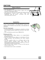
• Die Dunstabzugshaube ist ausschließlich zum Einsatz im privaten Haushalt und zur Beseitigung von Küchengerüchen vorgesehen.
• Unsachgemäßer Einsatz der Haube ist zu unterlassen.
• Große Flammen bei eingeschalteter Haube niemals unbedeckt lassen.
Achtung! Große Flammen bei eingeschalteter Haube niemals unbedeckt lassen.
• Die Intensivität der Flamme ist so zu regulieren, dass sie den Topfboden nicht überragt.
Achtung! Frittiergeräte müssen während des Gebrauchs stets beaufsichtigt werden: Überhitztes Öl kann
sich entzünden.
• Frittiergeräte müssen während des Gebrauchs stets beaufsichtigt werden: überhitztes Öl kann sich entzünden.
• Keine flambierten Speisen unter der Abzugshaube zubereiten: Brandgefahr.
• Dieses Gerät darf nicht von Personen, auch Kindern, mit verminderten psychischen, sensorischen und geistigern
Fähigkeiten, oder von Personen ohne Erfahrung und Kenntnisse benutzt werden, sofern sie nicht von für ihre Sicherheit verantwortlichen Personen beaufsichtigt und beim Gebrauch des Geräts angeleitet werden.
• Kinder dürfen sich nicht unbeaufsichtigt in der Nähe des Geräts aufhalten und auf keinen Fall mit dem Gerät spielen.
• ACHTUNG: Die zugänglichen Teile können sehr heiß werden, wenn sie mit Kochgeräten eingesetzt werden.”.
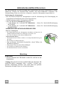
WARTUNG
• Bevor Wartungsarbeiten durchgeführt werden, muss die Stromzufuhr zur Haube unterbrochen werden, indem der
Stecker gezogen oder der Hauptschalter abgeschaltet wird.
• Bei der Filterwartung müssen die vom Hersteller empfohlenen Zeiträume zum Austauschen der Filter genauestens
eingehalten werden (Brandgefahr).
• Zur Reinigung der Haubenflächen empfehlen Wir ein feuchtes Tuch und ein mildes Flüssigreinigungsmittel.
• Bitte keine Reinigungsmittel mit Scheuermittel verwenden. Die Oberfläche wird damit verkratzt.
Das Symbol
auf dem Produkt oder seiner Verpackung weist darauf hin, dass dieses Produkt nicht als normaler Haushaltsabfall
zu behandeln ist, sondern an einem Sammelpunkt für das Recycling von elektrischen und elektronischen Geräten abgegeben
werden muss. Durch Ihren Beitrag zum korrekten Entsorgen dieses Produkts schützen Sie die Umwelt und die Gesundheit Ihrer
Mitmenschen. Umwelt und Gesundheit werden durch falsches Entsorgen gefährdet. Weitere Informationen über das Recycling
dieses Produkts erhalten Sie von Ihrem Rathaus, Ihrer Müllabfuhr oder dem Geschäft, in dem Sie das Produkt gekauft haben.
DE
3
36
CHARAKTERISTIKEN
Platzbedarf
DE
3
37
Komponenten
Pos.
1
2
2.1
2.2
7.1
7.1a
7.1b
9
14.1
15
25
Pos.
7.3
11
12c
12e
12f
12g
12h
12q
21
22
23
DE
St.
1
1
1
1
1
1
1
1
2
1
St.
1
4
6
2
2
4
4
4
1
8
4
St.
1
Produktkomponenten
Haubenkörper mit Schaltern,
Teleskopkamin bestehend aus:
oberer Kaminteil
unterer Kaminteil
Teleskopgerüst komplett mit Gebläse, bestehend aus:
oberer Gerüstteil
unterer Gerüstteil
Reduzierflansch ø 150-120 mm
Verlängerung Luftaustritt-Anschlussstück
Luftaustritt-Anschlussstück
Rohrschellen (nicht enthalten)
Montagekomponenten
Bügel für Anschlusshalter
Bügel ø 10
Schrauben 2,9 x 6,5
Schrauben 2,9 x 9,5
Schrauben M4 x 80
Schrauben M6 x 80
Schrauben 5,2 x 70
Schrauben 3,5 x 9,5
Bohrschablone
Unterlegscheiben ø 6,4
Schraubenmuttern M6
Dokumentation
Bedienungsanleitung
3
38
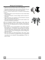
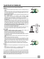
MONTAGE
Bohren der Decke/Trägerplatte und Montage des Teleskopgerüsts
Achtung: Bitte beachten Sie bei der Montage das Gewicht der kompletten Haube. Die Tragfähigkeit der Decke oder alternativ der Trägerplatte für diese Zugbelastung muss vor der Montage geprüft und gegebenenfalls durch die Anbringung von geeigneten Befestigungs- oder
Stabilisierungselementen hergestellt werden. Kann eine hinreichende Tragfähigkeit nicht sichergestellt werden, ist von einer Montage abzusehen.
BOHREN DER DECKE/TRÄGERPLATTE
• Mit Hilfe eines Lots den Kochmulden-Mittelpunkt an der Decke oder Trägerplatte ermitteln
und kennzeichnen.
• Die mitgelieferte Bohrschablone 21 so auf die Decke/Trägerplatte legen, dass die Schablonenmitte mit dem gekennzeichneten Mittelpunkt übereinstimmt und die Schablonenseiten
auf die Seiten der Kochmulde ausrichten.
• Die Mitte der Schablonenbohrungen kennzeichnen.
• Die gekennzeichneten Punkte bohren:
• Massivbeton-Decke: je nach verwendeten Beton-Dübeln.
• Decke aus Hohlkammer-Ziegeln mit 20 mm Wandungsstärke: ø 10 mm (sofort die mitgelieferten Dübel 11 einfügen).
• Holzbalkendecke: je nach verwendeten Holzschrauben.
• Holz-Trägerplatte: ø 7 mm.
• Durchgang für das Speisekabel: ø 10 mm.
• Luftaustritt (Abluftversion): je nach Durchmesser des Anschlussrohres für die Luftableitung.
• Zwei sich gegenüberliegende Schrauben festziehen und 4-5 mm Freiraum zur Decke belassen:
• bei Massiv-Betondecken mit speziellen Betondübeln, die nicht mitgeliefert werden;
• für Hohlkammer-Ziegeln mit ca. 20 mm Wandungsstärke die mitgelieferten Schrauben
12h verwenden;
• bei Holzbalken-Decken mit 4 Holzschrauben, die nicht mitgeliefert werden;
• bei Holz-Trägerplatten mit 4 Schrauben 12g, Unterlegscheiben 22 und Schraubenmuttern
23, die im Lieferumfang enthalten sind.
DE
3
39
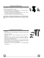
Montage des Teleskopgerüsts
• Die beiden Schrauben lösen, die den unteren Gerüstteil fixieren
und diesen aus dem Gerüst ziehen (an der Unterseite)
• Die beiden Schrauben lösen, die den oberen Gerüstteil fixieren
und diesen aus dem Gerüst ziehen (an der Oberseite).
Für eine eventuelle Regulierung der Gerüsthöhe folgendermaßen
vorgehen:
• Die Stellschrauben an den Gerüstseiten, die die beiden Säulen
vereinen, lösen.
• Den oberen Gerüstteil von oben einfügen und frei auf dem Gerüst lassen.
• Das Gerüst heben, die Langlöcher bei den Schrauben einrasten
und bis zum Anschlag laufen lassen;
• Die beiden Schrauben festziehen und die beiden anderen mitgelieferten Schrauben einschrauben;
Bevor die Schrauben definitiv festgezogen werden, kann eine
Regelung durch Bewegen des Gerüstes erfolgen, wobei darauf zu
achten ist, dass die Schrauben nicht aus dem Sitz des Regellangloches austreten.
• Wir verweisen auf die Notwendigkeit einer absolut sicheren
Befestigung des Teleskopgerüsts, die sowohl dem Eigengewicht der Haube wie auch dem seitlichen Druck, der auf das
Gerät einwirken kann, entsprechen muss. Nach erfolgter Montage ist zu prüfen, ob das Teleskopgerüst auch bei Biegebeanspruchung stabil ist.
• Sollte die Decke am Befestigungspunkt nicht robust genug
sein, muss der Installateur geeignete Platten und Gegenplatten
verwenden, die an strukturell widerstandsfähigen Teilen verankert werden.
DE
1
2
1
2
4
40
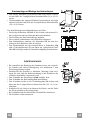
Anschluss der Abluftversion
Bei Abluftbetrieb kann die Haube vom Installateur wahlweise
mittels Rohr oder Schlauch (ø 150 oder 120 mm) an die Außenrohrleitung angeschlossen werden.
• Bei Verwendung eines Anschlussrohres ø 120 den Reduzierflansch 9 am Haubenaustritt anbringen.
• Das Rohr mit geeigneten Rohrschellen fixieren. Das hierzu
erforderliche Material wird nicht mitgeliefert.
• Eventuell vorhandene Aktivkohlefilter entnehmen.
ø 150
ø 120
25
9
25
Achtung! Alle Querschnittänderungen oder Richtungsänderungen des Abluftkanals reduzieren die Leistung der Haube.
Luftaustritt bei der Filterversion
• Die Anschlussverlängerungen 14.1 seitlich am Anschluss 15
einsetzen.
• Den Anschluss 15 am Haltewinkel 7.3 einsetzen und mit den
Schrauben fixieren.
• Den Haltewinkel 7.3 mit den Schrauben an der Oberseite befestigen.
• Sicherstellen, dass sich der Austritt der Anschlussverlängerungen 14.1 sowohl waagrecht als auch senkrecht auf Höhe der
Öffnungen des Kamins befindet.
• Den Anschluss 15 mittels eines starren oder flexiblen Rohrs
mit ø150 mm, das vom Installateur ausgewählt wird, an den
Austritt des Haubenkörpers anschließen.
• Sicherstellen, dass der Aktivkohlefilter zur Geruchsbindung
vorhanden ist.
DE
12c
7.3
14.1
15
12e
7.3
4
41
Kaminmontage und Montage des Haubenkörpers
• Den oberen Kaminteil positionieren und beim oberen Gerüstteil mit Hilfe der 2 mitgelieferten Schrauben 12c (2,9 x 6,5) fixieren.
• Gleichermaßen den unteren Kaminteil positionieren und beim
unteren Gerüstteil mit Hilfe der 2 mitgelieferten Schrauben 12c
(2,9 x 6,5) fixieren.
Vor dem Befestigen des Haubenkörpers am Gitter:
• Die beiden Schrauben 12f halb in die beiden vorbereiteten Löcher seitlich am unteren Gitterabschnitt einschrauben.
• Die Fettfilter aus dem Haubenkörper nehmen.
• Die eventuell vorhandenen Aktivkohlefilter ausbauen.
• Den Haubenkörper anheben, die Schrauben 12f bis zum Anschlag in die Langlöcher (Bez.A) stecken.
• Den Haubenkörper mit den mitgelieferten 4 Schrauben 12q
und 4 Unterlegscheiben 22 von unten am vorbereiteten Gitter
(Bez.B) befestigen und alle Schrauben endgültig festschrauben.
ELEKTROANSCHLUSS
• Bei Anschluss der Haube an das Stromnetz muss ein zweipoliger Schalter mit einem Öffnungsweg von mindestens 3 mm
zwischengeschaltet werden.
• Entfernen Sie die Fettfilter (s. Abschnitt „Wartung“) und versichern Sie sich, daß die Kabelverbindung in die Steckdose des
Gebläses einwandfrei eingesteckt wird.
• Den Verbinder der Steuerungen Cmd anschlie- ßen.
• Den Verbinder der Beleuchtung Lux anschließen.
• Den Verbinder wieder in die Verbindungsdose 24 stecken und
diese mit den 2 mitgelieferten Schrau-ben 12e (2,9 x 9,5) verschließen.
• Schließen Sie die Stecker im Inneren der Haube, um die Farbe
der Steckverbinder selbst entsprechen.
• Bei Umluftbetrieb den Aktivkohle-Geruchsfilter montieren.
• Die Fettfilter wieder montieren.
DE
24
12e
Lux
12c
Cmd
4
42
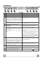
BEDIENUNG
Schalttafel
Taste
A
B
C
D
E
F
G
H
DE
Funktion
Schaltet den Gebläsemotor in Stufe 1 EIN/AUS
Reduziert die Betriebsstufe
Erhöht die Betriebsstufe
Aktiviert von jeder Betriebsstufe und auch bei abgestelltem Motor die Intensivstufe, die auf 6 Minuten
zeitbegrenzt ist. Nach Ablauf dieser Zeit schaltet das
System auf die zuvor eingestellte Stufe zurück. Ist
für die Beseitigung von sehr intensiven Kochdünsten
geeignet.
Mit zirka 5 Sekunden langem Druck, bei abgeschaltetem Motor und Beleuchtung, wird die Sättigungsanzeige für Kohlefilter aktiviert/deaktiviert..
Fu ktion 24H
Schaltet den Motor in Stufe 1 ein und saugt 10 Minuten pro Stunde.
Bei eingeschaltetem Filteralarm wird durch 3 Sekunden anhaltendes Drücken der Taste ein Reset des
Alarms ausgelöst.
Derlei Anzeigen sind nur bei abgestelltem Motor
sichtbar.
Funktion Delay
Aktiviert das automatische Ausschalten mit einer
Verzögerung von 30‘. Vervollständigt die Beseitigung von Restgerüchen. Kann von jeder Position aus
eingeschaltet werden und wird durch Drücken der
Taste oder Abstellen des Motors ausgeschaltet.
Mit zirka 5 Sekunden langem Druck der Taste bei
abgeschaltetem Motor und Beleuchtung wird die
Fernbedienung aktiviert/deaktiviert.
Schaltet die Beleuchtung auf 100% Helligkeit ein und
aus.
Bei längerem Druck der Taste schaltet die Beleuchtung auf eine gedimmte Helligkeit ein und aus.
Aktiviert/Deaktiviert die Antikondensat-Widerstände
(Temperatur wird in 10 Minuten erreicht)
Display
Zeigt die eingestellte Stufe an
Zeigt die eingestellte Stufe an
Zeigt die eingestellte Stufe an
Macht einmal pro Sekunde abwechselnd HI und die
Restzeit sichtbar.
FC+Punkt (2Mal Blinken)–Alarm aktiviert.
FC+Punkt (1Mal Blinken)–Alarm deaktiviert.
Zeigt 24 an und der Punkt unten rechts blinkt einmal
pro Sekunde während der Motor in Betrieb ist.
Wird durch Druck auf die Taste deaktiviert.
FF blinkt drei Mal.
Nach abgeschlossener Prozedur verlöscht die vorherige Anzeige.
FG zeigt an, dass die Metallfettilter gewaschen werden müssen. Dieser Alarm wird nach 100 effektiven
Betriebsstunden der Abzugshaube ausgelöst.
FC zeigt an, dass die Geruchsfilter (Aktiv-Kohle)
ausgetauscht werden müssen und die Metallfettfilter zu
waschen sind. Dieser Alarm wird nach 200 effektiven
Betriebsstunden der Abzugshaube ausgelöst.
Zeigt die Betriebsstufe an und der Punkt unten rechts
blinkt einmal pro Sekunde.
IR+Punkt (2Mal Blinken)–Alarm aktiviert.
IR+Punkt (1Mal Blinken)–Alarm deaktiviert.
Das entsprechende Symbol blinkt.
4
43
FERNBEDIENUNG (OPTION)
Dieses Gerät kann mit einer Fernbedienung gesteuert
werden, welche mit alkalischen Zink-Kohle-Batterien
1,5 V des Standardtyps LR03-AAA versorgt wird
(nicht mitgeliefert).
• Die Fernbedienung nicht in die Nähe von Hitzequellen legen.
• Batterien müssen vorschriftsmäßig entsorgt werden.
Bedienfeld der Fernbedienung
Motor
Motor EIN/AUS.
Reduziert die Betriebsstufe bei jedem Druck.
Erhöht die Betriebsstufe bei jedem Druck.
Intensivstufe
AntiKondensat
24H/ Delay
Beleuchtung
DE
Bei kurzem Druck: schaltet die Intensivstufe EIN/AUS
Bei längerem Druck: schaltet das Anti-Kondensatsystem EIN/AUS .
Bei kurzem Druck: Schaltet die Nachlauffunktion von 30 Minuten EIN/AUS. Auf
dem Display wird die Gebläsestufe sowie ein blinkender Punkt unten rechts aufgezeigt.
Bei zwei Sekunden langem Druck: schaltet die Funktion 24h EIN/AUS: Der Gebläsemotor schaltet in Stufe 1 ein und saugt 10 Minuten pro Stunde. Auf dem
Display wird die Nummer 24 und ein blinkender Punkt unten rechts angezeigt.
Bei kurzem Druck: schaltet die Beleuchtung EIN/AUS
Bei zwei Sekunden langem Druck: schaltet die Dimmfunktion
EIN/AUS
4
44
WARTUNG
Öffnen des Paneels
• Das Paneel herausziehen.
• Die Außenflächen mit einem feuchten Lappen und einem
neutralen Flüssigreiniger säubern.
• Auch Innen mit einem feuchten Lappen und einem neutralen
Reinigungsmittel säubern; keine nassen Tücher oder
Schwämme, oder gar Wasser verwenden, und keine
schleifenden Mittel einsetzen.
Metallfettfilter
Die Fettfilter sind spülmaschinengeeignet und müssen gewaschen
werden, sobald am Display die Aufschrift FG erscheint oder
mindestens alle 2 Monate, oder auch öfter, je nach Intensität des
Gebrauchs.
Reset des Alarmsignals
• Die Beleuchtung und den Absaugmotor abschalten und dann
die 24-Stunden-Funktion deaktivieren, falls diese zuvor aktiv
war.
• Die Taste E drücken (siehe Absatz GEBRAUCH).
Reinigung der Filter
• Das Komfort-Paneel öffnen, indem es zur entsprechenden
Kerbe gezogen wird
• Die Filter einzeln ausbauen, indem sie in den hinteren Teil der
Gruppe geschoben und gleichzeitig nach unten gezogen
werden.
• Die Filter waschen, ohne sie zu verbiegen, und vor dem
erneuten Einbau trocknen lassen. (Die Farbe der
Filteroberfläche kann sich mit der Zeit verändern, was aber die
Wirksamkeit keinesfalls beeinträchtigt.)
• Nun die Filter wieder einbauen, so dass der Griff nach der
äußeren Sichtseite zeigt.
• Die Komfort-Paneele wieder verschließen.
DE
4
45
Aktivkohle-Geruchsfilter (Filterversion)
Der Aktivkohlefilter ist nicht waschbar oder regenerierbar und muss ausgewechselt werden,
sobald am Display die Aufschrift FC erscheint, oder nach mindestens 4 Monaten. Die
Alarmmeldung, wenn zuvor aktiviert, erfolgt nur, wenn der Absaugmotor zugeschaltet ist.
Aktivierung des Alarmsignals
• Bei den Filterversionen der Abzugshauben wird die Alarmanzeige für Filtersättigung im
Augenblick der Installation oder in der Folge aktiviert.
• Die Beleuchtung und den Absaugmotor abstellen.
• Die Taste D zirka 5 Sekunden lang drücken.
• 2 Mal Blinken der Aufschrift FC+Pünktchen -- Alarm für Aktivkohlefiltersättigung
AKTIVIERT
• 1 Mal Blinken der Aufschrift FC+Pünktchen -- Alarm für Aktivkohlefiltersättigung
DEAKTIVIERT
AUSWECHSELN DES AKTIVKOHLE-GERUCHSFILTERS
Reset des Alarmsignals
• Die Beleuchtung und den Absaugmotor abschalten und dann die 24Stunden-Funktion deaktivieren, falls diese zuvor aktiv war.
• Die Taste E drücken (siehe Absatz GEBRAUCH).
Auswechseln des Filters
• Das Komfort-Paneel öffnen, indem es zur entsprechenden Kerbe gezogen wird
• Die Fettfilter aus Metall entfernen.
• Den gesättigten Aktivkohle-Geruchsfilter durch Öffnen der
Klammern ausbauen.
• Den neuen Filter in seinen Sitz einhängen.
• Die Fettfilter aus Metall wieder einbauen.
• Die Komfort-Paneele wieder verschließen.
Beleuchtung
LED-Strahler
• Für den Austausch der LED-Strahler wenden Sie sich bitte an den
Kundendienst.
Achtung: Dieses Gerät ist mit einer weißen LED-Lampe der Klasse 1M
gemäß EN 60825-1 ausgestattet: 1994 + A1:2002 + A2:2001; max.
gelieferte Lichtleistung @439nm: 7µW. Nicht direkt mit optischen
Instrumenten (Fernglas, Lupe, usw.) in das Licht schauen.
DE
4
46
TAVSIYELER VE ÖNERILER
Bu kullanma talimatι birden fazla cihaz modeli için geçerlidir.
Cihazιnιza uymayan bazι donanιm özellikleri tarif edilmiş olabilir.
MONTAJ
• Yalnιş veya eksik montajdan doğan herhangi bir zararιn sorumluluğu üreticiye ait
değildir.
• Davlumbaz ile pişirici cihazιn ocak kιsmι arasιndaki minimum güvenlik mesafesi 650
mm.dir (bazı modeller daha alçak seviyede bir yüksekliğe kurulabilir, hacim ve kurulum ile ilgili paragraflara bakınız).
• Besleme voltajιnιn, davlumbaz içerisine yerleştirilen bilgi etiketinde belirtilenle aynι
olup olmadιğιnι kontrol edin.
• Sιnιf I elektrikli aletleri için, güç kaynağιnιn yeterli topraklamayι sağlayιp
sağlamadιğιnι kontrol edin. Minimum 120 mm çapιnda bir boru yoluyla davlumbazι
çιkιş bacasιna bağlayιn. Baca bağlantιsι mümkün oldu- ğunca kιsa olmalιdιr.
• Davlumbaz borusunu yanιcι duman taşιyan baca deliğine (buhar kazanι, şömine,
vb.) bağlamayιn.
• Davlumbazιn elektrikle çalιşmayan aletlerle (örneğin; gazlι cihazlar) bağιntιlι olarak
kullanιlmamasι halinde çιkιş gazιnιn geri tepmesini önlemek amacιyla odada yeterli
bir havalandιrma sağlanmalιdιr. Temiz hava girişini temin etmek için mutfakta doğrudan dιşarιya açιlan bir açιklιk bulunmalιdιr. Cihazların bulunduğu mekan ile dış
çevre arasındaki azami basınç farkının 0,04 mbar’ı geçmemesi şarttır.
• Güç kablosunun hasar görmesi durumunda herhangi bir riskten kaçınmak için imalatçı ya da teknik servis tarafından değiştirilmelidir.
• Gaz ocak için montaj talimatları yukarıda belirtilen daha fazla mesafe varsa, bu hesaba alınmalıdır. Egzoz havası ile ilgili tüm yönetmeliklerle uyumlu olmalıdır.
2°
KULLANIM
• Davlumbaz mutfaktaki kokularιn emilmesi amacιyla evlerde kullanιm için
tasarlanmιştιr.Ticari ve endüstriyel amaçlar için kullanmayιnιz.
• Davlumbazι tasarlandιğι amaçlarιn dιşιnda kesinlikle kullanmayιnιz.
• Davlumbaz çalιşιrken altιnda kesinlikle yüksek çιplak ateş bιrakmayιn.
• Alev yoğunluğunu doğrudan tencerenin altιnda kalacak şekilde ayarlayιn, kenarlarιnι
sarmadιğιndan emin olun.
• Yağda kιzartma tavalarιnι kullanιrken sürekli olarak takip edin: fazla ιsιnan yağ tutuşabilir.
• Kapağın altında kıvılcımdan kaçının, yangın riski
• Bu alet, güvenliklerinden sorumlu kişiler tarafından kontrol edilmedikleri veya eğitilmedikleri sürece; fiziksel, duyumsal ve zihinsel kapasitesinde kısıtlama olan (çocuklar dahil) veya aleti kullanma tecrübesi ve bilgisi olmayan kişiler tarafından kullanılamaz.
• Bebeklerin, aletle oynamadıklarından emin olmak için kontrol edilmeli gerekir.
• “DİKKAT: Pişirme cihazlarında kullanılırken ulaşılabilir parçalar sıcak hale gelebilir.”
BAKIM
• Herhangi bir bakιm işlemini gerçekleştirmeden önce davlumbazι kapatιn veya fişini
çιkarιn.
• Filtreleri belirtilen zamanlarda temizleyin ve / veya değiştirin(Yangın riski).
• Cihazι nemli bir bez ve nötr bir sιvι deterjan kullanarak temizleyin.
Ürün veya paketi üzerindeki
sembolü, bu ürünün normal bir evsel atık olarak görülmemesi
ve bu tip elektrikli veya elektronik cihazların atıldığı dönüşümlü toplama noktalarına terkedilmesi
gerektiğine işaret eder. Bu ürünü gerektiği gibi elimine etme kurallarına uyarsanız çevre ve insan
sağlığı üzerindeki olumsuz etkilerini bertaraf etmeye katkı sağlamış olursunuz. Bu ürünün geri
dönüşüm koşulları hakkında daha ayrıntılı bilgi için hudutları içinde bulunduğunuz belediyenin
ilgili diaresine, atık yoketme servisine veya ürünün satıcısına danışınız.
TR
4
47
ÖZELLIKLER
Boyutlar
TR
4
48
Parçalar
Ref. Miktar Ürün Aksamı
1
1 Davlumbaz Gövdesi şunlardan oluşur: Kumandalar,
Işık ve Filtreler
2
1 Aşağıda belirtilen unsurları ile birlikte teleskopik baca:
2.1
1 Üst baca
2.2
1 Alt baca
7.1
1 Aspiratörlü teleskopik kafes aşağıdakilerden oluşur:
7.1a
1 Üst kafes
7.1b
1 Alt kafes
9
1 Redüksiyon flanşı ø 150-120 mm
14.1
2 Hava Çıkış Bağlantı Uzatması
15
1 Hava Çıkış Bağlantısı
25
Boru kerpeteni sarıcısı (dahil değil)
Ref. Miktar Kurulum Aksamı
7.3
1 Hava çıkış sabitleme desteği
11
4 Dübel ø 10
12c
6 Vida 2,9 x 6,5
12e
2 Vida 2,9 x 9,5
12f
2 Vida M4 x 80
12g
4 Vidalar M6 x 80
12h
4 Vida 5,2 x 70
12q
4 Vida 3,5 x 9,5
21
1 Delme planı
22
8 Rondela ø 6,4
23
4 Vida somunu M6
Miktar Dokümantasyon
1 Kullanım Kitapçığı
TR
4
49
MONTAJ
Tavan / Konsol delme işlemi ve Kafesin Sabitlenmesi
TAVANIN YADA KONSOLUN DELİNMESİ
• Bir şakül yardımıyla tavana ya da destek konsolüne pişirme tezgahının merkezini işaretleyiniz.
• Tavana veya konsola donanımla birlikte verilen delik delme şablonunu (21) dayayınız ve
bunun merkeziyle işaretlenen merkezi birbirine çakıştırınız. Yani şablonun ekseni ile pişirme tezgahı ekseni bir hizaya gelmiş olsun.
• Delik delme şablonuyla delikleri duvara işaretleyiniz.
• Şu şekilde delik deliniz:
• Masif beton tavan: beton dübelleri kullanarak.
• Direnç kalınlığı 20 mm ve üstte hava boşluğu olan tuğla tavan: 10 mm çapında delik (donanımla verilmiş dübelleri (11) hemen takınız)
• Ahşap tavan: ahşap dübelleri kullanarak.
• Ahşap konsola: 7 mm çapında delik deliniz.
• Elektrik besleme kablosunun geçişi için: ø 10 mm çapında.
• Hava Çıkışı (Aspiratörlü model): Dış hava tahliye borusu bağlantısının çapına göre.
• Tavana çaprazlamasına iki vida takıp 4-5 mm dışarıda bırakınız. Bu vidalar şöyle olmalıdır:
• Masif beton için buna uygun vida ve dübeller; bunlar donanımla verilmemiştir.
• Hava boşluklu tuğla tavan - yaklaşık 20 mm direnç kalınlıklı - bunun için donanımla verilmiş vidaları (12h) kullanınız.
• Ahşap tavana uygun vidalar: donanımda yoktur.
• Ahşap konsola: donanımdaki vidalar (12g), rondelalar (22) ve cıvatalar (23).
TR
5
50
Kafesin Sabitlenmesi
• Alt bacayı sabitleyen iki adet vidayı söküp kafesten çıkarınız
(alt kısımdan).
• Üst bacayı sabitleyen iki adet vidayı söküp kafesten çıkarınız
(üst kısımdan).
Kafesin yüksekliği ayarlanmak istenirse, şu şekilde hareket edilmelidir:
• Kafesin iki yanında bulunan sütunları birleştiren adet metrik
vidayı sökünüz;
• Kafesin yüksekliğini istediğiniz seviyede ayarlayıp daha önce
sökmüş olduğunuz adet vidayı tekrar takarak sıkınız;
• Yukarı kısımdan üst bacayı geçiriniz ve kafes üzerinde serbest
bırakınız;
• Kafesi yukarı kaldırınız, delikleri vidalara geçirip dayanana
kadar kaydırınız;
• İki adet vidayı sıkıp bilahare cihaz donanımıyla verilmiş olan
iki adet diğer vidayı da takınız;
1
2
1
2
Vidaları nihai olarak sıkmadan önce, kafesi ayar delikleri vidalardan çıkmadan kaydırmaya özen göstererek ayarlamak mümkündür.
• Kafesin sabitlenmesi hem Davlumbazın ağırlığını kaldırabilecek, hem de cihazın montajından sonra yandan gelebilecek
sarsmalara dayanacak şekilde mümkün olduğunca sağlam yapılmalıdır. Sabitleme işlemi bittikten sonra, Kafesi sarsınca ve
esnetince bile kaidenin sabit ve sağlam şekilde durduğunu
kontrol ediniz.
• Askı noktasında tavanın yeterince sağlam olmadığı hallerde,
montör buraya uygun sıkı bağlantılı levha ve plakalar uygulamak suretiyle tavan sağlamlığını arttırma yoluna gitmelidir.
TR
5
51
Bağlantılar
ASPİRATÖRLÜ MODEL HAVA ÇIKIŞI
Aspiratörlü modelin montajı için, davlumbaz, montörün seçeceği
150 yada 120 mm çapında sert veya esnek bir boru ile çıkış kanalına bağlanmalıdır.
• ø120 mm çapında boru ile bağlantı için, redüksiyon flanşını (9)
davlumbaz gövdesi çıkışına yerleştiriniz.
• Boruyu uygun kelepçelerle sıkarak sabitleyiniz. Bu malzeme
davlumbaz donanımıyla birlikte verilmemiştir.
• Varsa aktif karbonlu koku alma filtrelerini çıkarınız.
ø 150
ø 120
25
9
25
Filtre Edici Versiyon Hava Çıkışı
• 14.1 ekleme bileziği uzatmalarını yanal olarak 15 no.lu ekleme
bileziğine sokunuz.
• Vidaları sabitleyerek 15 no.lu bağlantıyı 7.3 Destek Dirseğine
ekleyiniz.
• 7.3 Destek dirseğini vidalarla üst bölüme sabitleyiniz.
• 14.1 ekleme bileziği uzatmaları çıkışının, gerek yatay, gerekse
dikey olarak, baca mentezlerinin hizasında bulunduğundan
emin olunuz.
• 15 no.lu Bağlantıyı, montaj görevlisinin seçimine göre ø150
mm çapında sert veya esnek bir hortum ile Davlumbaz Gövdesi Çıkışına bağlayınız.
• Aktif Karbonlu Koku önleyici Filtrenin bulunduğundan emin
olunuz.
TR
12c
7.3
14.1
15
12e
7.3
5
52
Baca montajı ve davlumbaz gövdesinin sabitlenmesi
• Üst Bacayı yerleştiriniz ve cihaz donanımındaki 2 adet vidayı
12c (2,9 x 6,5) kullanarak yukarı kısımdan Kafese sabitleyiniz.
• Aynı şekilde alt Bacayı da yerleştiriniz ve cihaz donanımındaki
2 adet vidayı 12c (2,9 x 6,5) kullanarak aşağı kısımdan Kafese
sabitleyiniz.
Davlumbaz Gövdesini Kafesli Izgaraya sabitlemeden önce:
• 2 adet 12f vidayı, yan konumda kafesin alt bölümünde mevcut
2 deliğe yarı şekilde vidalayın.
• Davlumbaz gövdesinden yağlanmaya karşı filtreleri çıkartın;
• Olası Aktif Karbonlu Kokuya Karşı Filtreleri Çıkartın.
• Davlumbaz Gövdesini kaldırın ve 12f vidaları yuvalara (ref.A)
oturtun.
• Donanımda mevcut olan 4 adet 12q vida ile ve 4 adet rondela
22 rondela ile davlumbaz gövdesini kafese sabitleyin (ref. B)
ve tüm vidaları iyice sıkıştırın.
ELEKTRİK BAĞLANTISI
• Davlumbazı Şebeke Beslemesine bağlarken, araya temas aralığı en az 3 mm olan çift kutuplu bir Elektrik Anahtarı koyunuz.
• Yağ tutucu Filtreleri çıkarınız (bkz. "Bakım" paragrafı) ve besleme kablosu soketinin Aspiratör prizine doğru takılı olduğunu
kontrol ediniz.
• Cmd kumandaları Soketini bağlayınız.
• Spot lamba konnektorlerini baglayiniz Lux.
• Her iki Soketi koruyucu Kutuya 24 koyunuz ve bunu cihaz donanımındaki 2 adet Vida ile 12e (2,9 x 9,5) kapatınız.
• Konnektörleri kendileri rengini eşleştirmek için kaput içinde
konnektörlerini bağlayın.
• Filtreli Modelde aktif karbonlu Koku Filtresini monte ediniz.
• Yağ Filtrelerini yeniden takınız.
TR
24
12e
Lux
12c
Cmd
5
53
KULLANIM
Kumanda Tablosu
Tuş
A
B
C
D
E
F
G
H
TR
Fonksiyon
Emme motorunu ilk hızda çalıştırır.
Çalışma hızını düşürür.
Çalışma hızını yükseltir.
Motor kapalıyken de herhangi bir hızdan Yoğun hıza
geçer, bu hız 6 dakika zaman ayarlıdır, bu sürenin
bitmesiyle sistem daha önceden ayarlanan hıza geri
döner. Pişirme sırasındaki dumanın fazla yayılmasını
engellemek için uygundur.
Bütün bağlantılar (Motor + Işık) kapalı olduğunda, 5
saniyeliğine tuşu basılı tuttuğunuzda Aktif Karbon
Filtre alarmı Devreye Girer / Devreden Çıkar.
24S İşlevi
Motoru ilk hızında çalıştırır ve saatte 10 dakikalık bir
aspirasyon sağlar.
Filtre alarmı durumunda ilgili tuşa 3 saniye boyunca
basarak alarmı sıfırlayabilirsiniz.
Bu bildirimler sadece motor kapalı iken görüntülenir.
Gösterge
Ayarlanan hızı görüntüler
Ayarlanan hızı görüntüler
Ayarlanan hızı görüntüler
HI ve sırayla kalan zamanı saniyede bir olarak
görüntüler.
FC+Nokta (2 Yanıp Sönme)–Alarm Devrede.
FC+Nokta (1 Yanıp Sönme)–Alarm Devre Dışı.
24 görüntülenir ve motor çalışmakta iken sağ alt
bölümdeki nokta saniyede bir kez yanıp söner.
Tuşa basılarak devreden çıkartılır.
FF üç kez yanıp söner.
Prosedür
tamamlandıktan
sonra
daha
önce
görüntülenen işaret söner:
FG yağlanmaya karşı metal filtrelerin yıkanması
gereğini işaret eder. Alarm Davlumbazın 100 saatlik
yoğun kullanım süresinden sonra devreye girmektedir.
FC karbon filtrelerin değiştirilmesi ve ayrıca
yağlanmaya karşı metal filtrelerin de yıkanması
gereğini işaret eder. Alarm Davlumbazın 200 saatlik
efektif çalışma süresinden sonra devreye girmektedir.
Gecikme İşlevi
Çalışmanın hızı görüntülenir ve sağ alt bölümdeki
30’ geciktirmeli otomatik kapanışı devreye alır. nokta saniyede bir kez yanıp söner.
Kalan kokuların giderilmesi için uygundur. Herhangi
bir konumdan devreye alınabilen bu komut, motoru
kapatmak veya düğmeye basmak sureti ile devre dışı
bırakılır.
Bütün bağlantılar (Motor + Işık) kapalıyken 5 IR+Nokta (2 Yanıp Sönme)–Alarm Devrede.
saniyeliğine tuşu basılı tuttuğunuzda Kumanda IR+Nokta (1 Yanıp Sönme)–Alarm Devre Dışı.
Devreye Girer/Devreden Çıkar.
Aydınlatma tesisatını maksimum yoğunlukta açar ve kapatır.
Yaklaşık 2 saniye boyunca düğmeye basılması aydınlatma cihazını “courtesy light” biçiminde açar
ve kapatır.
Yoğuşma önleme dayanıklılık işlevini aktive eder / İlgili sembol yanıp söner.
devreden çıkartır (10 dakika ısıtma).
5
54
TELEKUMANDA (OPSİYONEL)
Bu cihaza bir telekumanda ile de komut verilebilir; bu
kumanda 1,5 Voltluk çinko-karbonlu LR03-AAA tipi
standart alkalin pillerle çalışır (dahil değildir).
• Telekumandayı
ısı
kaynakları
yakınında
bırakmaynız.
• Pilleri çevreye atmayınız, bunlara ayrılmış çöp toplama kaplarına atınız.
Uzaktan Kumanda Panosu
Motor
Motor Açık / Kapalı
Her basışta çalışma hızını azaltır.
Her basışta çalışma hızını arttırır.
Yoğun
Yoğuşma
önleyici
Gecikme
(Delay)/24
H
Işık
Kısa basış: Yoğun işlevini aktive eder / devreden çıkartır.
Uzun basış: Yoğuşma önleme dayanıklılık işlevini aktive eder / devreden
çıkartır.
Kısa basış: Gecikme işlevini aktive eder / devreden çıkartır: 30 dakika sonra
otomatik kapanma özelliği. Çalışmanın hızı ekranda görüntülenir ve sağ alt
bölümdeki nokta saniyede bir kez yanıp söner.
2 saniye basış 24s işlevini aktive eder / devreden çıkartır: Motoru ilk hızında
çalıştırır ve saatte 10 dakikalık bir aspirasyon sağlar. Ekran 24 sayısını gösterir ve
sağ alt bölümdeki nokta saniyede bir kez yanıp söner.
Kısa basış Işıklar Açık / Kapalı
2 saniye basılı tutulduğunda: Courtesy Light Açık / Kapalı
BAKIM
Panelin açılması
• Panoyu çekerek açın.
• Dış taraftan nemli bir bez ve sıvı nötr deterjan ile temizleyiniz.
• İç taraftan nötr deterjan ve nemli bez kullanmak sureti ile
temizleyiniz; ıslak bez veya sünger kullanmayınız, su
sıkmayınız, aşındırıcı maddeler kullanmayınız.
Yağlanmaya karşı metal filtreler
Bulaşık makinesinde yıkanabilirler, ekranda FG sembolü
göründüğünde ya da yaklaşık her 2 aylık kullanım sonrasında
veya özellikle yoğun kullanım durumunda daha sıklıkla
yıkanmaları gerekir.
Alarm sinyalinin sıfırlanması
• Işıkları ve emme Motorunu kapatın, şayet 24h işlevi
devredeyse, kapatın.
• E tuşuna basın (Kullanım paragrafına bakın).
Filtrelerin Temizlenmesi
• Confort Panellerini uygun şekilde çekerek açın.
• Yağ önleyici Filtreleri, grubun arka bölümüne doğru iterek ve
aynı anda aşağıya doğru çekerek birer birer çıkarın.
• Kıvrılmalarını engelleyerek filtreleri yıkayınız ve tekrar
takmadan önce kurumaya bırakın. (Filtrenin yüzeyinin
renginde zaman içerisinde gözlenebilecek olan değişimler,
filtrenin etkinliğini etkilemez.)
• Tutamağın dış görünür tarafta olduğuna dikkat ederek filtreleri
tekrar monte edin.
• Confort Panellerini kapatın.
TR
5
56
Koku Emici Aktif Karbonlu Filtreler (Filtre Edici Sürüm)
Yıkanamaz, yeniden kullanılamaz, ekranda FC görüntülendiğinde veya en az 4 ayda bir
değiştirilir. Alarm sinyali, eğer önceden etkinleştirilmişse, sadece Aspirasyon Motoru
çalıştırıldığı zaman çalışır.
Alarmın devreye alınması
• Filtre edici sürümlü Davlumbazlarda, Filtrelerin dolma alarmı sinyali, kurulum anında veya
devamında devreye alınır.
• Işıkları ve aspiratör motorunu kapatın.
• Yaklaşık 5 saniye kadar D tuşuna basın.
• FC+Nokta yazısı 2 kez yanıp sönüyorsa C.A. Filtre doygunluk Alarmı DEVREDEDİR.
• FC+Nokta yazısı 1 kez yanıp sönüyorsa C.A. Filtre doygunluk Alarmı DEVRE
DIŞIDIR.
AKTİF KARBON KOKU ÖNLEYİCİ FİLTRENİN DEĞİŞTİRİLMESİ
Alarm sinyalinin sıfırlanması
• Işıkları ve emme Motorunu kapatın, şayet 24h işlevi devredeyse, kapatın.
• E tuşuna basın (Kullanım paragrafına bakınız).
Filtrenin Değiştirilmesi
• Confort Panellerini uygun şekilde çekerek açın.
• Yağ önleyici metalik filtreleri çıkarın.
• Dolmuş olan Koku Emici Aktif Karbonlu Filtreyi ilgili
kancalara müdahale ederek çıkartın.
• Yeni Filtreyi yuvasına takarak monte edin.
• Yağ önleyici metalik filtreleri yerine takın.
• Confort Panellerini kapatın.
Aydınlatma
Dikkat: Bu cihazda EN 60825-1: 1994 + A1:2002 + A2:2001
normuna uygun olarak 1M sınıfı beyaz LED lamba kullanılmıştır;
@439nm'de yayılan azami optik güç: 7µW. Optik aygıtlarla
(dürbün, büyüteç....) doğrudan bakmayın.
• Değiştirmek için Teknik Servisle bağlantı kurun. ("Edinmek
için teknik servisle bağlantı kurun").
TR
5
57
Franke S.p.a.
Via Pignolini,2
37019 Peschiera del Garda (VR)
www.franke.it
991.0351.106_ver4