1
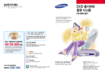
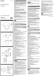
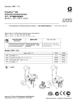
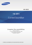
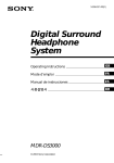
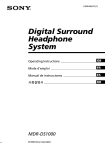
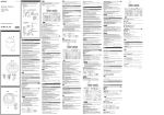
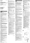
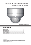
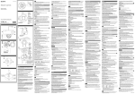
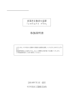
4-543-805-01(1) ◆各機能や設定について詳しくは、ユーザーガイドをご覧ください。 「I/Oケーブルの接続」をご覧ください。 ◆配線については、 ケーブルをカメラの横から引き出して配線する場合は、ペンチなどでつまん で折り取ってください。 Network Camera 設置説明書 Manuale di installazione Manual de instalación Руководство по установке Installation Manual Manuel d’installation Installationsanleitung 설치 설명서 [RJ45] LAN(ネットワーク)コネクタ(PoE) ネットワークケーブル(UTP、カテゴリー 5)を使用して、PoE*給電およびネッ 内面 SDカードスロット 別売のSDメモリーカードを装着することで、カメラの画像をメモリーカード ロックレバー ドームケースを取り外すとき、レバーを押しながらドームケースを回してく ださい。 リセットスイッチ てあります。この設置説明書をよくお読みのうえ、製品を安全にお使いください。お読 カメラヘッド みになったあとは、いつでも見られるところに必ず保管してください。 正常に動作している場合はインジケーターが点灯します。 NETWORK(ネットワーク)インジケーター ネットワークに接続されているときは点灯、または点滅します。ネットワー クに接続されていないときは消灯しています。 カメラ取り付け用ネジ穴(2か所) 取り付ける際、取り付けネジはしっかり締めてください。 カメラ本体 レンズ △画像上方マーク A 画像の上方向を示します。 カメラヘッド固定ネジ ネジをゆるめてからカメラヘッドを撮影したい方向に向け、そのあと締めて 固定します。 I/O(入出力)ポート 定格ラベル Camera head fixing screw Firstly, loosen the screw and point the camera head in the desired direction, then tighten the screw to secure in place. I/O (input/output) port Connect the supplied I/O cable. Rating Label This label shows the name of device and its electric rating. Hole for fall-prevention rope Attach the rope (sold separately). You can purchase the fall-prevention rope at the store of purchase or authorized Sony dealer. ˎˎIf you attach the camera in the height such as the wall or the ceiling, etc., entrust the installation to an experienced contractor or installer. ˎˎIf you install the camera on the ceiling, ensure that the ceiling is strong enough to withstand the weight of the camera plus the Mounting Adaptor and then install the camera securely. If the ceiling is not strong enough, the camera may fall and cause serious injury. ˎˎTo prevent the camera from falling, make sure to attach the fall-prevention rope (sold separately). ˎˎIf you attach the camera to the ceiling, check periodically, at least once a year, to ensure that the connection has not loosened. If conditions warrant, make this periodic check more frequently. ˎˎDo not install the camera in a location that is exposed to sunlight. (continued on the reverse side) Français Avant d’utiliser l’appareil, veuillez lire attentivement ce manuel et le conserver pour future référence. Manuel d’installation (le présent document) 本機の名称や、電気関係の定格情報が記載されています。 落下防止用ロープ取り付け穴 Ce Manuel d’installation indique les noms et fonctions des pièces et commandes de la Network Camera, fournit des exemples de raccordement et explique comment installer la caméra. Lisez impérativement le Manuel d’installation avant l’utilisation. 別売のロープを取り付けます。 お買い上げ店またはソニーのサービス窓口経由で購入できます。 設置 B Installation Indicates the image direction. À propos des manuels 付属のI/Oケーブルを接続します。 Fixez le câble anti-chute (vendu séparément). Vous pouvez vous procurer le câble anti-chute auprès du magasin qui vous a vendu la caméra ou auprès d’un revendeur Sony agréé. WARNING POWER(電源)インジケーター(緑) カメラに電源が供給されると、カメラ内部でシステムチェックを行います。 © 2014 Sony Corporation Printed in China Orifice pour câble anti-chute Installation 押しながら電源を供給すると、工場出荷時の設定に戻ります。 Cette étiquette indique le nom de l’appareil et sa classification électrique. mark し込んで確実に装着してください。 SNC-XM631 Screw holes for installing the camera (2 positions) Étiquette de classification Befestigen Sie das Drahtseil (separat erhältlich). Sie können ein Fallschutzdrahtseil bei der Vertriebsstelle oder einem autorisierten Sony-Vertragshändler erwerben. Lens 本機は、SD規格およびSDHC規格のメモリーカードにのみ対応しています。 この設置説明書には、事故を防ぐための重要な注意事項と製品の取り扱いかたを示し Loch für Fallschutzdrahtseil Raccordez le câble d’E/S fourni. Camera unit 装着の際は、図のように端子面を定格ラベル側に向けて差し込み、最後まで押 ることがあります。 Port d’E/S (entrée/sortie) The indicator lights up or flashes when the camera is connected to the network. The indicator is off when the camera is not connected to the network. (*PoE: Power over Ethernetの略です。IEEE802.3afに準拠しています。) に記録できます。 電気製品は、安全のための注意事項を守らないと、火災や人身事故にな NETWORK indicator トワーク通信を行います。 ◆ 接続については、裏面の「電源ネットワークへの接続」をご覧ください。 お買い上げいただきありがとうございます。 Diese Kennzeichnung zeigt den Namen des Geräts sowie seine elektrische Bemessung an. Make sure to tighten the screws securely when installing the camera. ドームケース Typenschild Desserrez la vis, dirigez le bloc de caméra dans la direction de votre choix, puis serrez à nouveau la vis. POWER indicator (Green) ケーブル引き出し用スリット Vis de montage du bloc de caméra When the power is supplied to the camera, the camera starts checking the system. If the system is normal, the indicator lights up. Règles de sécurité (fourni) Le document Règles de sécurité décrit l’utilisation correcte de la caméra. Lisez-le attentivement. ˎ 壁や天井など高所へ設置する際は、専門の工事業者に依頼してください。 ˎ 天井への設置は、本体と設置用アダプターを含む重量に充分耐えられる強度が あることをお確かめの上、確実に取り付けてください。充分な強度がないと落 下して大けがの原因となります。 ˎ 落下事故防止のため、別売のロープを必ず取り付けてください。 ˎ 天井へ設置した場合は、1年に一度は取り付けがゆるんでいないことを点検し てください。また、使用状況に応じて点検の間隔を短くしてください。 ˎ 直射日光が当たる場所へは設置しないでください。 (裏面へ続く) English Before operating the unit, please read this manual thoroughly and retain it for future reference. About the Manuals Vous devez installer Adobe Reader sur votre ordinateur pour pouvoir lire ce manuel. Vous pouvez télécharger Adobe Reader gratuitement depuis le site Web d’Adobe. Safety Regulations (supplied) 1 Ouvrez le fichier index.html situé sur le CD-ROM. 2 Sélectionnez le manuel que vous souhaitez lire, puis cliquez sur ce Utilisation du manuel sur CD-ROM SNC easy IP setup Guide (stored in the CD-ROM) User’s Guide/Application Guide (Web) The User’s Guide describes how to set up the camera and how to control the camera via a Web browser. After installing and connecting the camera correctly, operate referring to this User’s Guide. The supplied CD-ROM includes the setup program for assigning an IP address. The information for how to set up an IP address is also included in the disc in PDF format. User’s Guide and Application Guide can be downloaded from the disc, or the following URL: http://www.sony.net/ipela/snc Using the CD-ROM manual 設置説明書(本書) この設置説明書には、 カメラ本体の各部の名称や設置、接続方法が記載されてい ます。操作の前に必ずお読みください。 安全のために(同梱) カメラを安全に使うための注意事項が記載されています。必ずお読みください。 SNC easy IP setupガイド(CD-ROMに収録) ユーザーガイド/アプリケーションガイド(Web) カメラのセットアップの方法や、Webブラウザを介したコントロールの方法が 記載されています。 設置説明書にしたがってカメラを正しく設置、接続したあと、ユーザーガイドを ご覧になってカメラを操作してください。 ソフトウェアの使いかた http://www.sony.net/ipela/snc CD-ROMマニュアルの使いかた Adobe Readerがインストールされたコンピューターで、各ガイドを閲覧できま す。 Adobe Readerは、Adobeのウェブサイトから無償でダウンロードできます。 11 22 読みたいガイドを選択してクリックする。 CD-ROMに収録されているindex.htmlファイルを開く。 窓口経由で購入できます。 AdobeおよびAdobe Readerは、Adobe Systems Incorporated(アドビシス テムズ社)の商標です。 付属のCD-ROMに収録されているセットアッププログラムを使ってIPアドレス を割り当ててください。 セットアップ方法について詳しくは、SNC easy IP setupガイドをご覧ください。 各部の名称と働き ケーブルは、出荷時は接続されていません。 側面 Location and Function of Part I/O (input/output) cable (supplied) Provided with one sensor input and one alarm output. The wires comply with the following signals: Pin name 1 2 Sensor In + Sensor In − (GND) Color Red Black Pin No. Pin name 3 4 Alarm Out + Alarm Out − Color Blue White ˎˎFor details about functions and settings, refer to the User’s Guide. ˎˎFor wiring, refer to “Connecting the I/O cable” on the reverse side. Connect a network cable (UTP, category 5) to this port to communicate with a network or PoE* system. (*PoE stands for Power over Ethernet. It is pursuant to IEEE802.3af.) ˎˎFor details on connection, refer to “Connection to the electrical power network” on the reverse side. 赤 黒 ピン 番号 3 4 ピン名称 アラーム出力+ (Alarm Output +) アラーム出力− (Alarm Output –) SD card slot Image data in the camera can be recorded to a memory card by inserting an SD memory card (sold separately) into the slot. When inserting, point the contact area at the rating label side (referring to the illustration), and be sure to insert it completely. This unit is only compatible with SD and SDHC memory cards. Lock lever Reset switch 各ワイヤーは次の信号に対応しています。 色 青 白 To reset the camera to the factory default settings, hold down the reset switch and supply power to the camera. Camera head Attribution de l’adresse IP Hinweis zu den Anleitungen Installationsanleitung (dieses Dokument) Diese Installationsanleitung erläutert die Bezeichnungen und Funktionen der Teile und Bedienungselemente der Network Camera, enthält Anschlussbeispiele und erläutert die Einrichtung der Kamera. Bitte lesen Sie die Installationsanleitung vor der Inbetriebnahme durch. Sicherheitsbestimmungen (mitgeliefert) Die Sicherheitsbestimmungen beschreiben die sichere Benutzung der Kamera. Lesen Sie diese unbedingt durch. SNC easy IP setup-Anleitung (auf der CD-ROM enthalten) Bedienungsanleitung/Anwendungsanleitung (Web) Die Bedienungsanleitung erläutert die Einrichtung der Kamera und die Steuerung der Kamera über einen Webbrowser. Nachdem Sie die Kamera ordnungsgemäß installiert und angeschlossen haben, können Sie mit der Inbetriebnahme gemäß dieser Bedienungsanleitung beginnen. Verwenden der Software Die mitgelieferte CD-ROM enthält das Einrichtungsprogramm für das Zuweisen einer IP-Adresse. Die CD-ROM enthält außerdem eine Datei im PDF-Format, in der beschrieben wird, wie Sie eine IP-Adresse einrichten. Die Bedienungsanleitung und die Anwendungsanleitung können von der CD ROM oder der folgenden URL heruntergeladen werden: http://www.sony.net/ipela/snc Verwenden der Anleitung auf der CD-ROM Die Anleitung kann auf einem Computer, auf dem Adobe Reader installiert ist, gelesen werden. Sie können Adobe Reader kostenlos von der Adobe-Website herunterladen. 1 Öffnen Sie die Datei index.html auf der CD-ROM. 2 Wählen Sie die Anleitung aus, die Sie lesen möchten, und klicken Sie Attribuez l’adresse IP à l’aide du programme de configuration du CD-ROM fourni. Pour plus de détails sur la configuration de l’adresse IP, reportez-vous au Guide de l’outil SNC easy IP setup. Emplacement et fonction des pièces Wenn Sie die CD-ROM nicht mehr besitzen oder wenn sie beschädigt ist, können Sie Ersatz bei Ihrem Sony-Händler oder der Sony-Servicevertretung erwerben. Adobe und Acrobat Reader sind Markenzeichen von Adobe Systems Incorporated in den Vereinigten Staaten und/oder in anderen Ländern. Broche n° 1 2 Broche Nom de la broche Couleur Nom de la broche n° Entrée capteur + (Sensor In +) Entrée capteur − (TERRE) (Sensor In − (GND)) Rouge Noir 3 Sortie alarme + (Alarm Out +) 4 Sortie alarme − (Alarm Out −) Couleur Bleu Blanc Das Kabel ist bei Lieferung nicht angeschlossen. Das Kabel ist mit einem Sensoreingang und einem Alarmausgang ausgestattet. Die Adern sind mit folgenden Signalen belegt: Pin-Bezeichnung Farbe PinNr. Pin-Bezeichnung Farbe 3 Alarmausgang + (Alarm Out +) Blau Sensoreingang + Rot (Sensor In +) Sensoreingang − (GND) Schwarz (Sensor In − (GND)) 4 Alarmausgang − (Alarm Out −) Weiß ˎˎWeitere Informationen zu Funktionen und Einstellungen finden Sie in der Bedienungsanleitung. ˎˎInformationen zur Herstellung der Anschlüsse finden Sie unter „Anschließen des I/O-Kabels“ auf der Rückseite. Ausbrechlasche Wenn Sie die Kabel durch die Seite der Kamera führen, brechen Sie die Ausbrechlasche heraus (mit einer Zange usw.). LAN-Anschluss (Netzwerk) (PoE) [RJ45] Kuppelgehäuse Logement pour carte SD En este Manual de instalación se describen los nombres y funciones de las partes y controles de la Network Camera, ejemplos de conexión e instrucciones para configurar la cámara. Asegúrese de leer el Manual de instalación antes de utilizarla. Normativas de seguridad (suministrado) En la guía Normativas de seguridad se describe el uso seguro de la cámara. Es muy importante leer esta guía. Guía de SNC easy IP setup (almacenada en el CD-ROM) Guía del usuario/Guía de la aplicación (web) En la Guía del usuario se describe cómo configurar la cámara y cómo controlarla a través de un explorador web. Después de instalar y conectar la cámara correctamente, consulte esta Guía del usuario para utilizarla. El CD-ROM suministrado incluye el programa de configuración necesario para asignar una dirección IP. El disco también incluye información en formato PDF sobre la configuración de una dirección IP. La Guía del usuario y la Guía de la aplicación se pueden descargar desde el disco o desde la siguiente dirección URL: http://www.sony.net/ipela/snc Utilización del manual del CD-ROM El manual se puede leer en un ordenador con Adobe Reader instalado. Puede descargar Adobe Reader gratuitamente desde el sitio web de Adobe. Innen SD-Kartensteckplatz Bilddaten von der Kamera können auf einer SD-Speicherkarte (gesondert erhältlich) aufgezeichnet werden, wenn Sie eine Speicherkarte in den Einschub einsetzen. Der Kontaktbereich sollte beim Einschieben (wie in der Abbildung gezeigt) auf die Typenschildseite zeigen. Stellen Sie zudem sicher, dass die Karte vollständig eingeschoben ist. Das Gerät ist nur mit SD- und SDHC-Speicherkarten kompatibel. Sperrhebel Drücken Sie den Hebel nach innen, drehen Sie das Kuppelgehäuse und nehmen Sie dann das Kuppelgehäuse von der Kameraeinheit ab. Il est possible d’enregistrer les données image de la caméra sur une carte mémoire en insérant une carte mémoire SD (vendue séparément) dans le logement. Placez la zone de contact face à l’étiquette indiquant la puissance nominale (en vous reportant à l’illustration), puis insérez la carte à fond. Cet appareil est compatible uniquement avec des cartes mémoire SD et SDHC. Schalter zum Zurücksetzen Levier de verrouillage POWER-Anzeige (Grün) Zum Zurücksetzen der Kamera auf die werkseitigen Standardeinstellungen halten Sie den Schalter zum Zurücksetzen gedrückt und schließen dann die Kamera an eine Stromquelle an. Kamerakopf Asigne la dirección IP con ayuda del programa de configuración incluido en el CD-ROM suministrado. Para obtener más información sobre la configuración de la dirección IP, consulte la Guía de SNC easy IP setup. Lateral Incorpora una entrada de sensor y una salida de alarma. Los cables son compatibles con las siguientes señales: Nombre clavija Entrada sensor + (Sensor In +) Entrada sensor − (Tierra) (Sensor In − (GND)) Núm. Color clavija Nombre clavija Color Rojo 3 Salida alarma + (Alarm Out +) Azul Negro 4 Salida alarma − (Alarm Out −) Blanco ˎˎPara obtener más información sobre las funciones y los ajustes, consulte la Guía del usuario. ˎˎPara obtener información sobre el cableado, consulte “Conexión del cable de E/S” en el dorso. Al pasar los cables por la parte lateral de la cámara, utilice unos alicates para separar la brida preperforada. Conecte un cable de red (UTP, categoría 5) a este puerto para comunicarse con una red o sistema PoE*. (*PoE significa Alimentación a través de Ethernet (del inglés Power over Ethernet). Cumple la norma IEEE802.3af.) ˎˎPara obtener más información sobre la conexión, consulte “Conexión a la red eléctrica” en el dorso. Interior Los datos de imagen de la cámara se pueden grabar en una tarjeta de memoria insertando una tarjeta de memoria SD (vendida por separado) en la ranura. Cuando vaya a insertar la tarjeta de memoria, dirija la zona de contacto hacia el lado de la etiqueta de clasificación (consulte la ilustración) y verifique que la introduce por completo. Esta unidad solo es compatible con tarjetas de memoria SD y SDHC. Palanca de bloqueo Presione la palanca hacia dentro, gire la cúpula y, a continuación, retire la cúpula de la unidad de la cámara. Botón de reinicio Para recuperar los ajustes predeterminados de fábrica de la cámara, mantenga pulsado el interruptor de reinicio y conecte la cámara a la corriente. Parte superior de la cámara Indicador POWER (Verde) Cuando se suministra corriente a la cámara, esta comienza a comprobar el sistema. Si el sistema está normal, este indicador se enciende. Indicador NETWORK El indicador se ilumina o parpadea si se conecta la cámara a la red. El indicador permanece apagado si la cámara no se encuentra conectada a la red. Orificios de tornillos de montaje de la cámara (2 posiciones) Asegúrese de apretar bien los tornillos cuando instale la cámara. Cámara Objetivo Schraubenlöcher zur Montage der Kamera (2 Positionen) Puerto de E/S (entrada/salida) Le témoin s’allume ou clignote lorsque la caméra est reliée au réseau. Le témoin est éteint lorsque la caméra n’est pas reliée au réseau. Orifices des vis de montage de la caméra (2 positions) Marca Afloje primero el tornillo y dirija la parte superior de la cámara hacia la dirección deseada; a continuación, apriete el tornillo para fijarlo. Conecte el cable de E/S suministrado. Etiqueta de valor nominal Esta etiqueta muestra el nombre del dispositivo y su clasificación eléctrica. Objektiv Orificio para el cable antidesprendimiento -Markierung Fije el cable (se vende por separado). Puede adquirir el cable antidesprendimiento en la tienda en la que compró la unidad o en un distribuidor autorizado de Sony. Gibt die Bildausrichtung an. Serrez correctement ces vis lors de l’installation de la caméra. Kamerakopf-Befestigungschraube Caméra Objectif Lösen Sie zuerst die Schraube und richten Sie den Kamerakopf so aus, dass er in die gewünschte Richtung zeigt, und ziehen Sie dann die Schraube zur sicheren Befestigung an. Repère I/O-Anschluss (Eingang/Ausgang) Ce repère indique le sens de l’image. Ranura para tarjetas SD Tornillo de fijación de la parte superior de la cámara Témoin NETWORK Zum Anschließen des mitgelieferten I/O-Kabels. Il CD-ROM in dotazione include il programma di impostazione per l’assegnazione dell’indirizzo IP. Le informazioni su come impostare un indirizzo IP sono contenute anche nel disco in formato PDF. La Guida per l’utente e la Guida applicativa possono essere scaricate dal disco o dal seguente indirizzo: http://www.sony.net/ipela/snc Uso del manuale su CD-ROM Instalación ADVERTENCIA ˎˎSi instala la cámara en un lugar elevado, como un muro o un techo, deje la instalación en manos de un instalador especializado. Правила по технике безопасности (прилагаются) В правилах по технике безопасности описывается безопасное использование камеры. Обязательно прочитайте этот документ. Руководство по программе SNC easy IP setup (находится на компакт-диске) Руководство пользователя/руководство по применению (сеть) В руководстве пользователя описывается процедура настройки камеры и управление камерой через веб-браузер. После установки и правильного подключения данной камеры по вопросам дальнейшего ее использования см. данное руководство пользователя. Использование программного обеспечения На прилагаемом компакт-диске содержится программа установки для назначения IP-адресов. Сведения по установке IP-адреса также находятся на диске в файле формата PDF. Руководство пользователя и руководство по применению можно также найти на диске или загрузить со следующего адреса URL: http://www.sony.net/ipela/snc Руководство можно прочитать на компьютере с установленной программой Adobe Reader. Программу Adobe Reader можно загрузить бесплатно на веб-сайте компании Adobe. 1 Откройте файл index.html на компакт-диске. 2 Выберите и откройте руководство, которое хотите прочитать. Примечание В случае утери или повреждения компакт-диска новый компакт-диск можно приобрести у дилера Sony или в пункте продажи продукции Sony. Adobe и Acrobat Reader являются товарными знаками Adobe Systems Incorporated в США и/или других странах. Assegnazione dell’indirizzo IP Assegnare l’indirizzo IP utilizzando il programma di impostazione contenuto nel CD-ROM in dotazione. Per i dettagli su come impostare l’indirizzo IP, fare riferimento alla Guida di SNC easy IP setup. Cavetto I/O di ingresso/uscita (in dotazione) Dotato di un ingresso per sensore e di un’uscita per allarme. I conduttori sono conformi con i seguenti segnali: Pin n. Nome pin Ingresso sensore + (Sensor In +) Ingresso sensore – (massa) (Sensor In − (GND)) Colore Pin n. Rosso Nero 1 Вход датчика + Красный (Sensor In +) Вход датчика – (GND) Черный (Sensor In − (GND)) Colore 3 Uscita allarme + (Alarm Out +) Blu 4 Uscita allarme − (Alarm Out −) Bianco ˎˎPer informazioni sulle funzioni e sulle impostazioni, vedere la Guida per l’utente. ˎˎPer il cablaggio, fare riferimento a “Collegamento del cavetto I/O” sul retro. Per far passare i cavi attraverso il lato della telecamera, utilizzare un paio di pinze per staccare la flangia preforata (con pinze e così via). Collegare un cavetto di rete (UTP, categoria 5) a questa porta per comunicare con una rete o un sistema PoE*. (*PoE è l’abbreviazione di Power over Ethernet. È conforme con IEEE802.3af). ˎˎPer informazioni dettagliate sul collegamento, vedere “Collegamento alla rete elettrica” sul retro. Custodia a cupola Interno Slot per scheda SD È possibile registrare i dati dell’immagine nella telecamera su una scheda di memoria SD (venduta a parte) inserendola nello slot. Quando si inserisce la scheda, puntare l’area con i contatti verso il lato con l’etichetta dei valori nominali (facendo riferimento all’illustrazione) e accertarsi di inserirla completamente. Questa unità è compatibile solo con schede di memoria SDHC e SD. Premere la leva verso l’interno e ruotare la custodia a cupola, quindi rimuovere quest’ultima dall’unità telecamera. Interruttore reset Per ripristinare la telecamera alle impostazioni predefinite in fabbrica, accendere la telecamera tenendo premuto l’interruttore reset. Testa telecamera Spia POWER (Verde) All’accensione, la telecamera inizia a controllare il sistema. Se il funzionamento del sistema è regolare, la spia si accende. Spia NETWORK Indica la direzione dell’immagine. Vite di fissaggio testa telecamera Allentare prima la vite e puntare la testa della telecamera nella direzione desiderata, quindi serrare la vite per fissarla in posizione. Porta I/O di ingresso/uscita Collegare il cavetto I/O fornito. Etichetta dei valori nominali Su questa etichetta sono riportati il nome del dispositivo e i dati di alimentazione nominali. Foro per il cavo di ritenuta Fissare il cavo (venduto a parte). È possibile acquistare il cavo di ritenuta presso il negozio dove è stato fatto l’acquisto oppure da un rivenditore Sony autorizzato. Installazione AVVERTENZA ˎˎSe si monta la telecamera in posizione elevata, come muri o soffitto, ecc., affidare l’operazione a installatori o ditta di montaggio esperti. ˎˎSe si installa la telecamera sul soffitto, assicurarsi che quest’ultimo sia sufficientemente robusto per reggere il peso della telecamera e dell’adattatore di montaggio, quindi, installare la telecamera in modo sicuro. Se il soffitto non è abbastanza robusto, la telecamera potrebbe cadere e causare ferite gravi. ˎˎPer evitare che la telecamera cada, aver cura di montare il cavo di ritenuta (venduto a parte). ˎˎSe la telecamera viene montata al soffitto, verificare periodicamente, almeno una volta all’anno, che il montaggio non si sia allentato. Se necessario, ripetere questo controllo periodico più frequentemente. ˎˎNon installare la telecamera in luoghi esposti alla luce solare. (continua sul retro) Русский Видеокамера Перед началом работы с устройством внимательно прочитайте данное руководство и сохраните его для справки в будущем. О руководствах Руководство по установке (данный документ) CD-ROM의 index.html 파일을 엽니다. 읽으려는 설명서를 선택하고 클릭합니다. 주의점 CD-ROM을 분실했거나 손상된 경우 Sony 대리점이나 Sony 서비스 센터에서 새것을 구입하실 수 있습니다. 케이블 은 연결되지 않은 상태로 출고됩니다. 센서 입력 하나와 알람 출력 하나가 제공됩니다. 다음 신호에 적합한 와이어입니다: 3 Синий 1 4 Выход сигнала − (Alarm Out −) Белый 2 Цвет ˎˎДля получения дополнительной информации о функциях и настройках см. руководство пользователя. ˎˎСведения о проводах см. в разделе “Подключение кабеля I/O” на обратной стороне. При пропускании кабелей через боковую поверхность камеры используйте плоскогубцы, чтобы отломить удаляемый фланец (с помощью плоскогубцев и т.д.). Разъем LAN (сети) (PoE) [RJ45] Подключите сетевой кабель (UTP, категория 5) к этому разъему для связи с сетью или системой PoE*. (*PoE означает Power over Ethernet (питание по Ethernet). Соответствует IEEE802.3af.) ˎˎДля получения дополнительной информации о подключении см. раздел “Подключение к электрической сети” на обратной стороне. Купольный корпус Внутренняя часть Разъем для карты SD Данные изображений в камере можно записывать на карту памяти, вставив карту памяти SD (продается отдельно) в разъем. При установке карты памяти направьте область контактов в сторону наклейки с данными (как показано на рисунке) и обязательно вставьте ее до упора. Данное устройство поддерживает только карты памяти SD и SDHC. Рычаг блокировки Нажмите на рычаг вовнутрь и поверните купольный корпус, затем отсоедините купольный корпус от корпуса камеры. Кнопка сброса Чтобы сбросить настройки камеры к заводским значениям по умолчанию, нажмите и удерживайте переключатель сброса настроек при включенном питании камеры. Головка камеры Индикатор POWER (зеленый) 핀 번호 핀 이름 컬러 센서 입력 + (Sensor In +) 센서 입력 -(GND) (Sensor In (GND)) 핀 번호 빨강 3 검정 4 알람 출력 (Alarm Out -) 파랑 흰색 녹아웃 타입 플랜지 카메라 측면으로 케이블을 통과시킬 때 플라이어를 사용하여 녹아웃 플랜지를 끊어내십시오(플라이어 등 사용). LAN(네트워크) 커넥터(PoE) [RJ45] 네트워크 또는 PoE* 시스템과 통신하려면 네트워크 케이블(UTP, 카테고리 5)을 이 포트에 연결합니다. (*PoE는 Power over Ethernet의 약어이며 IEEE802.3af와 호환됩니다.) 연결에 대한 내용은 뒷면의 "전력 네트워크에 대한 연결"을 참조하십시오. 돔 케이스 내부 SD 카드 슬롯 SD 메모리 카드(별매)를 슬롯에 끼워 메모리 카드에 카메라의 영상 데이터를 기록할 수 있습니다. 삽입 시 접촉부가 등급 라벨 쪽을 향하게 하고(그림 참조) 끝까지 삽입하십시오. 본 기기는 SD 및 SDHC 메모리 카드만 호환됩니다. 잠금 레버 레버를 안쪽으로 누르고 돔 케이스를 돌린 다음, 카메라 유닛에서 돔 케이스를 분리합니다. 재설정 스위치 카메라를 출고 시 기본값으로 재설정하려면 재설정 스위치를 누른 상태에서 카메라에 전원을 공급하십시오. 카메라 헤드 POWER 표시등(녹색) 카메라에 전원이 공급되면 카메라가 시스템 검사를 시작합니다. 시스템이 정상이면 표시등이 점등됩니다. NETWORK 표시등 카메라가 네트워크에 연결되면 표시등이 점등되거나 깜박입니다. 카메라가 네트워크에 연결되지 않으면 표시등이 꺼집니다. 카메라 설치용 나사 구멍(2군데) Индикатор NETWORK 렌즈 Отверстия для винтов для установки камеры (2 положения) 컬러 기능 및 설정에 대한 자세한 내용은 사용자 가이드를 참조하십시오. 배선에 대한 내용은 뒷면의 "I/O 케이블 연결"을 참조하십시오. 카메라 설치 시 나사를 단단히 조이십시오. Данный индикатор загорается или мигает, если камера подключена к сети. Данный индикатор выключается, если камера не подключена к сети. 핀 이름 알람 출력 + (Alarm Out +) Если на камеру подается питание, камера начинает выполнять проверку системы. Если система в порядке, загорается индикатор. 카메라 유닛 마크 영상 방향을 나타냅니다. Обязательно надежно затяните винты при установке камеры. 카메라 헤드 고정 나사 Камера 먼저 나사를 풀고 카메라 헤드를 원하는 방향으로 돌린 다음, 나사를 조여 제자리에 고정합니다. Объектив Фиксирующий винт головки камеры Contrassegno CD-ROM 설명서 사용 Adobe Reader가 설치된 컴퓨터에서 이 설명서를 읽을 수 있습니다. Adobe Reader는 Adobe 웹 사이트에서 무료로 다운로드할 수 있습니다. Выход сигнала + (Alarm Out +) Fori di installazione telecamera (2 posizioni) Obiettivo 부속된 CD-ROM에는 IP 주소 할당용 설정 프로그램이 포함되어 있습니다. IP 주소를 설정하는 방법에 대한 내용도 디스크에 PDF 형식으로 포함되어 있습니다. 사용자 가이드 및 응용 프로그램 가이드는 디스크나 다음 URL에서 다운로드할 수 있습니다. http://www.sony.net/ipela/snc Название контакта Значок Unità telecamera 소프트웨어 사용 № контакта La spia si accende o lampeggia quando la telecamera è collegata alla rete. La spia è spenta quando la telecamera non è collegata alla rete. Verificare di stringere le viti in sicurezza quando si installa la telecamera. 사용자 가이드에서는 카메라를 설치하는 방법과 웹 브라우저를 통해 카메라를 조작하는 방법을 설명합니다. 카메라를 정확히 설치하고 연결한 후에 본 사용자 가이드를 참조하여 조작하십 시오. I/O(입력/출력) 케이블(부속) Фланец удаляемого типа Nome pin SNC easy IP setup 가이드(CD-ROM에 저장) 사용자 가이드/응용 프로그램 가이드(웹) 옆면 Оборудован одним входом датчика и одним выходом сигнала. Провода соответствуют следующим сигналам: 2 Цвет 안전 수칙은 안전한 카메라 사용에 대해 다룹니다. 반드시 읽어 보십시오. 부속된 CD-ROM의 설정 프로그램을 사용하여 IP 주소를 할당합니다. IP 주소를 설정하는 자세한 방법은 SNC easy IP setup 가이드를 참조하십 시오. Кабель I/O (входа/выхода) (прилагается) Название контакта 안전 수칙(부속) 각부 위치 및 기능 Вид сбоку № контакта 본 설치 설명서에서는 네트워크 카메라의 각 부분과 조작 버튼의 이름 및 기능에 대해 설명하고 연결 방식 및 카메라 설정 방법을 설명합니다. 조작하기 전에 반드시 설치 설명서를 읽으십시오. IP 주소 할당 Кабель не подключен на момент отправки изделия. Adobe e Adobe Reader sono marchi commerciali di Adobe Systems Incorporated negli Stati Uniti e/o in altri paesi. 본 설명서에 대하여 Adobe 및 Acrobat Reader는 미국 및/또는 기타 국가에서 Adobe Systems Incorporated의 상표입니다. Расположение и функции компонентов In caso di perdita o di danneggiamento del CD-ROM, è possibile acquistarne uno nuovo da un rivenditore Sony o rivolgendosi all’assistenza Sony. 본 기기를 작동하기 전에 반드시 본 설명서를 숙지하고, 설명서는 나중을 위해 잘 보관하십시오. 1 2 Назначьте IP-адрес с помощью программы установки на прилагаемом компакт-диске. Для получения дополнительной информации о настройке IP-адреса см. руководство по программе SNC easy IP Setup. 1 Aprire il file index.html nel CD-ROM. 2 Selezionare e fare clic sul manuale che si desidera leggere. 한국어 설치 설명서(본 문서) Назначение IP-адреса Il manuale può essere letto esclusivamente su un computer sul quale sia installato Adobe Reader. È possibile scaricare gratuitamente Adobe Reader dal sito Web di Adobe. Leva di blocco Conector LAN (red) (PoE) [RJ45] Die Anzeige leuchtet oder blinkt, wenn die Kamera ans Netzwerk angeschlossen ist. Die Anzeige leuchtet nicht, wenn die Kamera nicht ans Netzwerk angeschlossen ist. Kameraeinheit La Guida per l’utente descrive come configurare la telecamera e come controllarla tramite un browser Web. Dopo avere correttamente montato e collegato la telecamera, utilizzarla facendo riferimento a questa Guida per l’utente. 2 В данном руководстве по установке описываются названия и функции компонентов и органов управления сетевой камеры, приводятся примеры подключений и даются инструкции по настройке камеры. Перед использованием камеры обязательно прочтите данное руководство по установке. Использование руководства на компакт-диске Connettore LAN (rete) (PoE) [RJ45] Cable de E/S (entrada/salida) (suministrado) Indica la dirección de la imagen. Lorsque l’alimentation électrique est fournie à la caméra, celle-ci commence à vérifier le système. Si le système est normal, le témoin s’allume. Guida di SNC easy IP setup (nel CD-ROM) Guida per l’utente/Guida applicativa (Web) Flangia preforata NETWORK-Anzeige Achten Sie bei der Montage der Kamera darauf, dass die Schrauben fest angezogen sind. Le Regole di sicurezza illustrano come utilizzare la videocamera in modo sicuro. Leggerle attentamente. 1 Commutateur de réinitialisation Témoin POWER (vert) Regole di sicurezza (in dotazione) Lato Nota Wenn die Kamera mit Strom versorgt wird, überprüft die Kamera das System. Wenn das System normal arbeitet, leuchtet die Anzeige. Bloc de caméra Questo manuale di installazione descrive il nome e la funzione delle parti e dei comandi della telecamera di rete, fornisce degli esempi di collegamento e le procedure di montaggio della telecamera. Ricordare di leggere il manuale di installazione prima di utilizzare la telecamera. Alla consegna, il cavetto non è collegato. Si ha perdido el CD-ROM o está dañado, puede adquirir uno nuevo a través de un distribuidor Sony o de un servicio técnico Sony. Poussez le levier vers l’intérieur pour tourner le logement dôme, puis retirez celui-ci du bloc de caméra. Pour rétablir les réglages par défaut de la caméra, maintenez le commutateur de réinitialisation enfoncé et mettez la caméra sous tension. Manuale di installazione (questo documento) Ubicazione e funzione delle parti 1 Abra el archivo index.html en el CD-ROM. 2 Seleccione y haga clic en el manual que desee leer. 2 Informazioni sui manuali Nota Utilización del software 1 Italiano Leggere attentamente questo manuale prima di utilizzare l’unità, e conservarlo per riferimenti futuri. Utilizzo del software Manual de instalación (este documento) Cúpula Bride avec pièce amovible Logement dôme Acerca de los manuales Brida preperforada ˎˎPour plus d’informations sur les fonctions et les réglages, reportez-vous au Guide de l’utilisateur. ˎˎPour le câblage, reportez-vous à la section « Raccordement du câble d’E/S » au verso. Raccordez un câble réseau (UTP, catégorie 5) à ce port pour communiquer avec un réseau ou un système PoE*. (*PoE signifie Power over Ethernet, à savoir alimentation par Ethernet. Ce protocole est conforme à la norme IEEE802.3af.) ˎˎPour plus de détails sur le raccordement, reportez-vous à la section « Raccordement au réseau électrique » au verso. Antes de poner en funcionamiento la unidad, lea detenidamente este manual y consérvelo para referencias futuras. Núm. clavija Stecken Sie ein Netzwerkkabel (UTP, Kategorie 5) in diesen Anschluss, um eine Verbindung mit einem Netzwerk oder PoE*-System herzustellen. (*PoE bedeutet Power over Ethernet (Spannungsversorgung über Ethernet). Entspricht den Richtlinien IEEE802.3af.) ˎˎWeitere Informationen zum Anschluss finden Sie unter „Anschließen an das Stromnetz“ auf der Rückseite. Lorsque vous faites passer les câbles à travers le côté de la caméra, utilisez par exemple des pinces pour couper la bride avec pièce amovible. Español El cable no se suministra conectado de fábrica. Position und Funktion der Komponenten 2 ˎˎWenn Sie die Kamera in großer Höhe anbringen, wie an einer Wand oder Decke usw., überlassen Sie die Montage einem erfahrenen Kundenbetreuer oder Installateur. ˎˎWenn Sie die Kamera an der Decke anbringen, stellen Sie sicher, dass die Decke ausreichend stark ist, um das Gewicht der Kamera und des MontageAdapters zu tragen, und bringen Sie die Kamera dann sicher an. Wenn die Decke für die Kamera nicht stabil genug ist, kann es zu einem Herabfallen und ernsthaften Verletzungen kommen. ˎˎBefestigen Sie unbedingt ein Fallschutzdrahtseil (separat erhältlich), um ein Herabfallen der Kamera zu verhindern. ˎˎWenn Sie die Kamera an der Decke befestigen, prüfen Sie regelmäßig (mindestens einmal im Jahr) nach, dass sich die Verbindung nicht gelockert hat. Wenn es die Umstände zulassen, sollten Sie diese Kontrolle häufiger durchführen. ˎˎInstallieren Sie die Kamera nicht an einem Ort, der Sonnenlicht ausgesetzt ist. (Fortsetzung auf der Rückseite) Ubicación y función de las piezas Zuweisen der IP-Adresse 1 WARNUNG Asignación de la dirección IP Hinweis PinNr. Installation Adobe y Acrobat Reader son marcas comerciales de Adobe Systems Incorporated en Estados Unidos y/o en otros países. darauf. I/O-Kabel (Eingangs-/Ausgangskabel) (mitgeliefert) Intérieur Knockout type flange Inside Bitte lesen Sie dieses Handbuch vor der Benutzung des Geräts sorgfältig durch und bewahren Sie es zum späteren Nachschlagen auf. Seite Connecteur LAN (réseau) (PoE) [RJ45] Press the lever inward and turn the dome case, then remove the dome case from the camera unit. I/O(入出力)ケーブル(付属) 1系統のセンサー入力と1系統のアラーム出力を備えています。 2 Assign the IP address using the setup program in the supplied CD-ROM. For details on how to set up the IP address, see SNC easy IP Setup Guide. Dome case 本機にIPアドレスを割り当てる センサー入力+ Assigning the IP address LAN (network) connector (PoE) [RJ45] ご注意 (Sensor Input +) センサー入力−(GND) (Sensor Input – (GND)) Adobe and Acrobat Reader are trademarks of Adobe Systems Incorporated in the United States and/or other countries. When threading the cables through the side of the camera, use pliers to break off the knockout flange (with pliers, etc.). CD-ROM が破損または紛失した場合は、お買い上げ店またはソニーのサービス 1 If you have lost or damaged the CD-ROM, you can purchase a new one from your Sony dealer or Sony service counter. Pin No. Adobe et Acrobat Reader sont les marques de commerce d’Adobe Systems Incorporated aux États-Unis et/ou dans d’autres pays. Fourni avec une entrée pour capteur et une sortie d’alarme. Les fils correspondent aux signaux suivants : Note Side Si vous avez perdu ou endommagé le CD-ROM, vous pouvez acheter un CD-ROM de remplacement auprès de votre revendeur Sony ou du service clientèle Sony. Câble d’E/S (entrée/sortie) (fourni) The cable is not connected at the time of shipment. 付属のCD-ROMには、IPアドレスを割り当てるためのセットアッププログラム が収納されています。また、セットアップ方法についての情報がPDF形式で記録 されています。 ユーザーガイドやアプリケーションガイドをご覧になりたい場合は、CD-ROM からダウンロードしていただくか、もしくは次のURLからダウンロードできま す。 Remarque Côté 1 Open the index.html file in the CD-ROM. 2 Select and click on the manual that you want to read. 説明書について Deutsch D’origine le câble n’est pas raccordé. The manual can be read on a computer with Adobe Reader installed. You can download Adobe Reader free from the Adobe website. 日本語 ˎˎSi vous fixez la caméra en hauteur, notamment sur un mur ou au plafond, confiez l’installation à un installateur expérimenté. ˎˎSi vous installez la caméra au plafond, assurez-vous que le plafond est suffisamment solide pour supporter le poids de la caméra et celui de l’adaptateur de montage avant de procéder à l’installation. Dans le cas contraire, la caméra risquerait de tomber et de provoquer de graves blessures. ˎˎPour empêcher la caméra de tomber, fixez impérativement le cordon métallique anti-chute (vendu séparément). ˎˎSi vous installez la caméra au plafond, vérifiez l’installation périodiquement (au moins une fois par an) pour vous assurer que le montage est toujours solide. Si les conditions le permettent, effectuez cette vérification périodique plus fréquemment. ˎˎN’installez pas la caméra dans un endroit exposé aux rayons directs du soleil. (suite au verso) Verwenden Sie das Einrichtungsprogramm auf der mitgelieferten CD-ROM, um die IP-Adresse zuzuweisen. Weitere Informationen zur Zuweisung der IP-Adresse finden Sie in der SNC easy IP setup-Anleitung. dernier. Using the software 色 Le CD-ROM fourni contient un programme d’attribution d’adresse IP. Le disque contient également des informations, au format PDF, sur la configuration d’une adresse IP. Vous pouvez télécharger le Guide de l’utilisateur et le Manuel d’application à partir du disque ou de l’URL suivante : http://www.sony.net/ipela/snc This Installation Manual describes the names and functions of parts and controls of the Network Camera, gives connection examples and explains how to set up the camera. Be sure to read the Installation Manual before operating. ピン名称 Utilisation du logiciel Installation Manual (this document) ピン 番号 Le Guide de l’utilisateur explique comment installer la caméra et commander cette dernière via un navigateur Web. Après avoir installé et raccordé correctement la caméra, suivez les instructions de ce Guide de l’utilisateur. The Safety Regulations describes the secure usage of camera. Be sure to read it. Guide de l’outil SNC easy IP setup (sur le CD-ROM) Guide de l’utilisateur/Manuel d’application (Web) AVERTISSEMENT ˎˎSi instala la cámara en el techo, compruebe que el techo sea lo suficientemente resistente para aguantar el peso de la cámara y del adaptador de montaje y, seguidamente, instale la cámara correctamente. Si el techo no soporta ese peso, la cámara podría caerse y provocar graves daños. ˎˎPara evitar que la cámara se caiga, asegúrese de colocar el cable antidesprendimiento (se vende por separado). ˎˎSi instala la cámara en el techo, compruebe regularmente, al menos una vez al año, que la conexión no se haya aflojado. Si las condiciones lo permiten, se debe llevar a cabo esta comprobación con más frecuencia. ˎˎNo instale la cámara en un lugar sometido a la luz solar. (continúa en el dorso) Указывает направление съемки. Сначала ослабьте винт и установите головку камеры в требуемое положение, затем затяните винт, чтобы закрепить ее. Порт I/O (входа/выхода) Подключите прилагаемый кабель I/O. Наклейка с данными На данной наклейке содержится название устройства и электрические характеристики. Отверстие для троса для предотвращения падения Закрепите трос (продается отдельно). Для приобретения троса для предотвращения падения обратитесь в магазин, где была совершена покупка, или к авторизованному дилеру Sony. Установка ПРЕДУПРЕЖДЕНИЕ ˎˎУстановку видеокамеры на высоте, например на стене, на потолке и т.д., должен выполнять опытный подрядчик или монтажник. ˎˎПри установке видеокамеры на потолке убедитесь, что потолок достаточно прочен, чтобы выдержать вес видеокамеры и переходника крепления, после чего надежно установите камеру. Если потолок недостаточно прочен, камера может упасть и причинить тяжелые травмы. ˎˎДля предотвращения падения камеры закрепите ее с помощью троса для предотвращения падения (продается отдельно). ˎˎПри установке камеры на потолке необходимо периодически, не реже одного раза в год, проверять надежность крепления. В зависимости от условий проводите периодические проверки чаще. ˎˎНе устанавливайте камеру в месте под солнечными лучами. (продолжение на обратной стороне) I/O(입력/출력) 포트 부속된 I/O 케이블을 연결합니다. 등급 라벨 이 라벨에는 장치의 이름과 전기 등급이 표시되어 있습니다. 추락 방지 로프용 구멍 로프(별매)를 부착합니다. 추락 방지 로프는 카메라를 구입한 상점이나 공인 Sony 대리점에서 구입할 수 있습니다. 설치 경고 벽이나 천장 등과 같은 높은 장소에 카메라를 부착하려면 설치 경험이 있는 시공자 또는 설치 전문가에게 맡기십시오. 천장에 카메라를 설치하려면 천장이 카메라와 마운팅 어댑터의 무게를 지탱할 만큼 견고한지 확인한 다음 카메라를 단단히 설치하십시오. 천장이 견고하지 않으면 카메라가 떨어져서 중상을 입을 수도 있습니다. 카메라가 떨어지지 않도록 반드시 추락 방지 로프(별매)를 부착하십시오. 카메라를 천장에 부착한 경우 최소한 1년에 한 번씩 주기적인 검사를 통해 연결이 느슨해지지 않았는지 확인하십시오. 가능하면 이러한 정기 점검을 더 자주 수행하십시오. 햇빛이 비치는 장소에 카메라를 설치하지 마십시오. (뒷면에서 계속) C H 56.5 (2 1/4) 33 (1 5/16) WARNING The required mounting screws differ depending on the installation location and its material. If you do not secure the camera with the appropriate mounting screws, the camera may fall off. Connecting the I/O Cable φ104.5 (4 /8) 1 2 単位:mm / Unit: mm (inches) / Unité : mm (pouces) / Einheit: mm (Zoll) / Unidad: mm (pulgadas) / Unità: mm (pollici) / Единицы измерения: мм (дюймы) / Өлшем бірлігі: мм (дюймдер) / 단위: mm (인치) b 単位:mm / Unit: mm (inches) / Unité : mm (pouces) / Einheit: mm (Zoll) / Unidad: mm (pulgadas) / Unità: mm (pollici) / Единицы измерения: мм (дюймы) / Өлшем бірлігі: мм (дюймдер) / 단위: mm (인치) D I/Oケーブルへの配線図 / Wiring diagram for the I/O cable / Schéma de raccordement du câble d’E/S / Schaltplan für das I/O-Kabel / Diagrama de cableado para el cable de E/S / Diagramma di collegamento per il cavetto I/O / Схема проводов для кабеля I/O / I/O 케이블용 배선도 3.3 V カメラ内部 / Camera inside / Intérieur de 外部 / Outside / Extérieur / Außerhalb la caméra / Innerhalb der Kamera / Interior / Exterior / Esterno / Снаружи / 외부 de la cámara / Interno della telecamera / Внутри камеры / 카메라 내부 メカニカルスイッチ / Mechanical switch / Contacteur mécanique / Mechanischer Schalter / Interruptor mecánico / Interruttore meccanico / Механический переключатель / 기계식 스위치 10 kΩ 2.2 kΩ 10 kΩ Sensor input + または / or / ou / oder / o / oppure / или / 또는 10 kΩ GND GND Sensor input − (GND) オープンコレクター出力装置 / Open collector output device / Dispositif de GND sortie à collecteur ouvert / OpenCollector-Ausgangsgerät / Dispositivo de salida de colector abierto / Dispositivo di uscita a collettore aperto / Устройство вывода с открытым коллектором / 오픈 컬렉터 출력 장치 カメラ内部 / Camera inside / Intérieur de la caméra / Innerhalb der Kamera / Interior de la cámara / Interno della telecamera / Внутри камеры / 카메라 내부 5V 外部 / Outside / Extérieur / Außerhalb / Exterior / Esterno / Снаружи / 외부 R Alarm Output + 回路例 / Circuit example / Exemple de circuit / Beispielschaltkreis / Ejemplo de circuito / Esempio di circuito / Пример цепи / 회로 예제 Alarm Output – E 1 日本語 カメラの取り付け位置を決める カメラの撮影方向を決めてから、付属のテンプレートを使って配線用の穴φ25 (-a)をあけ、カメラ取り付け用穴(2か所) (-b)の位置を決めます。 取り付けネジについて カメラには、φ4.5 mmの穴が2か所あいています。この穴を利用し、設置する場 所や材質により、使用するネジ類が異なります。 (ネジは付属していません。) 鋼材の場合:M4ネジとナットで固定してください。 (六角ボルトは使用できませ ん。) 木材の場合:タッピンネジ(呼び径4)で固定してください。板厚は15 mm以上 必要です。 コンクリート壁の場合:ドライビット、またはプラグボルトで固定してください。 (M4ネジのボルト頭部形状:ナベネジ、六角ボルトは使用できません。) ジャンクションボックスの場合:ジャンクションボックスのネジ穴に合ったネ ジで固定してください。 (ネジの頭部形状:φ7 mm 高さ4 mm以下) 設置する場所や材質により、適切な取り付けネジを使用してください。適切な取 り付けネジを使用しないと落下して大けがの原因になります。 I/Oケーブルの接続 I/Oケーブルの各ワイヤーは、イラストのように接続してください。 カメラを取り付ける 1 ドームケースを外す。 ドームケース側面の溝(-a)にマイナスドライバーを差し込み、ドーム ケースを反時計方向に回転させる。 ドームケースを外す。 落下防止用のロープ(別売) (-b)をカメラと天井または壁に取り付ける。 2 3 ネットワークケーブルを取り付ける。 4 I/Oケーブルを差し込む。 5 カメラを取り付ける。 のネジ位置に合わせて、ネジ(付属していません)で締め付ける。 ご注意 カメラの取り付けは、0℃以上で行ってください。 1 2 3 カメラヘッド固定ネジ(-a)を2 ∼ 3回転ゆるめる。 カメラを調整して、撮影したい方向にレンズを向ける。 カメラヘッド固定ネジを締めて固定する。 (推奨締め付けトルク:0.6 N・m) ˎ カメラヘッド固定ネジをゆるめずにカメラヘッドの向きを調整すると、内部の 部品が変形することがあります。 ˎ レンズの回転方向は、±175°で止まります。回転できる範囲を超えてレンズ を回すと、内部の配線が破断される恐れがあります。 ドームカバーの凸マーク(-a)をカメラ本体の凹マーク(-b)に合わ せてはめ込む()。ロックされるまで、時計方向に回転させる()。 2 ドームカバーに付いている保護シートをはがす。 接続 Notes ˎˎ Adjusting the camera head angle without first loosening the camera head fixing screw may damage internal parts. ˎˎ Lens rotation direction is ±175°. If you turn the lens beyond the movable range of rotation, the wiring inside the camera may be damaged. Attaching the Dome Case 1 市販のネットワークケーブル(ストレートケーブル)を使い、本機のネットワーク コネクタとPoE(*)給電機能を持った装置(ハブなど)を接続してください。 ご注意 電源を入れたあと、すぐに電源を切らないでください。電源を切る場合は、5分 程度お待ちください。 主な仕様 圧縮方式 映像圧縮方式 最大フレームレート カメラ 撮像素子 5 同期方式 最低被写体照度 JPEG/H.264 30 fps 1/2.9 型CMOS(Exmor) 有効画素数:約214万画素 Connection to the electrical power network Connect the network connector of the camera to a PoE* supported device (such as a hub) using the network cable (straight, not supplied). The electrical power is supplied through the network cable. For details, refer to the instruction manuals of the PoE* supported devices. (* PoE: The acronym for Power over Ethernet. IEEE802.3af standard compliant devices.) Do not turn off the camera immediately after turning it on. Wait for at least five minutes before turning off the camera. View-DR オフ/ VE* オフ/オートゲイン最大 値 MAX / 50 IRE (IP) / 30 fps カラー:0.3 lx 白黒:0.3 lx 焦点距離 最大口径比 画角 レンズ可動角度 1/2.9 type CMOS (Exmor) Effective picture elements: Approx. 2,140,000 Synchronization Internal synchronization Minimum illumination View-DR Off/VE* Off/Auto gain control maximum rate MAX/50 IRE (IP)/30 fps Color: 0.3 lx Black & White: 0.3 lx * VE stands for Visibility Enhancer. LANポート(PoE) I/Oポート 10BASE-T/100BASE-TX、オートネゴシエーション センサー入力:1ポート、MAKE接点/ BREAK接点切 換可 アラーム出力:1ポート(半導体リレー+/−50V、0.4A 以下) (本体とは電気的に絶縁) SDメモリーカードスロット その他 a G a 電源電圧 IEEE802.3af準拠(PoE方式) 消費電力 4.0 W(PoE CLASS 2) 使用温度 −10℃ ∼ +50℃ 起動温度 0℃ ∼ 50℃ 保存温度 −30℃ ∼ +60℃ 動作湿度 20% ∼ 80% 保存湿度 20% ∼ 80% 外形寸法(直径/高さ) Φ104.5 mm × 56.5 mm(突起部含まず) 質量 約200 g 付属品 テンプレート(1)、I/Oケーブル(1)、CD-ROM(付属 プログラム) (1)、安全のために、設置説明書(一式) 本機の仕様および外観は、改良のため予告なく変更することがありますが、ご了 承ください。 English Deciding the Installation Location of the Camera After deciding the direction in which the camera will shoot, make the required hole for the connecting cables using the supplied template (-a). Then decide the two mounting hole positions to install the camera (-b). f = 2.8 mm F2.0 1920 × 1080 (aspect ratio 16:9): Horizontal: 113°, Vertical: 61° Pan: 350° Tilt: 0° to 60° Rotation: −175° to +175° Mounting screws The camera has two ø 4.5 mm (3/16 inch) mounting holes. The required mounting screws differ depending on the installation location and its material. (Mounting screws are not supplied.) Steel wall or ceiling: Use M4 bolts and nuts. (Hexagon head bolt should not be used.) Wooden wall or ceiling: Use M4 tapping screws. The panel thickness must be 15 mm (5/8 inch) or more. Concrete wall: Use anchors, bolts and plugs suitable for concrete walls. (Head shape of M4 bolt: Pan head screw or hexagon head bolt should not be used.) Raccordez le connecteur réseau de la caméra à un périphérique compatible PoE* (un concentrateur, par exemple) à l’aide du câble réseau (droit, non fourni). L’alimentation provient du câble réseau. Pour plus d’informations, reportez-vous au Mode d’emploi du périphérique compatible PoE*. (* PoE : acronyme de Power over Ethernet. Périphériques conformes à la norme IEEE802.3af.) Ne mettez pas la caméra hors tension immédiatement après l’avoir mise sous tension. Patientez au moins cinq minutes avant de mettre la caméra hors tension. Spécifications Format de compression vidéo JPEG/H.264 Fréquence d’images maximale 30 ips * VE signifie Visibility Enhancer. Interface LAN port (PoE) SD memory card slot Angle mobile Sensor input: 1 port, MAKE contact/BREAK contact switchable Alarm output: 1 port (Semiconductor relay +/–50 V, 0.4 A or less) (electrically isolated from the camera unit) Interface Port d’E/S Power supply IEEE802.3af compliant (PoE system) Power consumption 4.0 W (PoE CLASS 2) Operating temperature –10°C to +50°C (15°F to 122°F) Activation temperature 0°C to 50°C (32°F to 122°F) Storage temperature –30°C to +60°C (–22°F to +140°F) Operating humidity 20% to 80% Storage humidity 20% to 80% Dimensions (diameter/height) ø 104.5 mm (4 1/8 inches) × 56.5 mm (2 1/4 inches) (not including the projecting parts) Mass Approx. 200 g (7 oz) Supplied accessories Template (1), I/O cable (1), CD-ROM (supplied programs) (1), Safety Regulations, Installation Manual (this document) (1 set) La caméra dispose de deux orifices de montage de ø 4,5 mm (3/16 pouce). Les vis de montage requises varient selon l’emplacement d’installation et les matériaux. (Les vis de montage ne sont pas fournies.) Paroi ou plafond en acier : utilisez des boulons et des écrous M4. (Vous ne devez pas utiliser de vis à six pans.) Paroi ou plafond en bois : utilisez des vis autotaraudeuses M4. L’épaisseur du panneau doit être d’au moins 15 mm (5/8 pouce). Mur en béton : utilisez des ancrages, des boulons et des chevilles pour murs en béton. (Forme de la tête de la vis M4 : vous ne devez pas utiliser de vis à tête cylindrique ni de vis à six pans.) Boîte de jonction : utilisez des vis s’adaptant aux orifices de la boîte de jonction. (Forme de la tête de la vis : ø 7 mm (9/32 pouce) Hauteur 4 mm (3/16 pouce) ou moins) AVERTISSEMENT Les vis de montage requises varient selon l’emplacement d’installation et les matériaux. Si vous ne fixez pas solidement la caméra avec les vis de montage appropriées, la caméra risque de tomber. Raccordez les fils du câble d’E/S de la manière illustrée en . 1 2 3 4 5 10BASE-T/100BASE-TX, négociation automatique Entrée capteur : 1 port, contact à FERMETURE/ contact à OUVERTURE commutable Sortie alarme : 1 port (relais à semiconducteur +/−50 V, 0,4 A maximum) (isolé électriquement du bloc caméra) Einbauort der Kamera auswählen Retirez le logement dôme. Insérez un tournevis à lame plate dans la fente de l’extérieur du logement dôme (-a) et tournez le logement dôme dans le sens inverse des aiguilles d’une montre. Retirez le logement dôme. Fixez le cordon métallique anti-chute (vendu séparément) (-b) au plafond ou au mur et à la caméra. Raccordez le câble réseau. Insérez le câble d’E/S. Installez la caméra. Alignez les deux trous de vis sur la caméra aux positions de vis sur le plafond ou le mur à l’aide du gabarit fourni. Serrez les vis (vendues séparément). Remarque Installez la caméra dans un environnement dont la température est supérieure à 0 °C (32 °F). Réglage de la direction et du champ de prise de vue de la caméra 1 Desserrez la vis de fixation du bloc de caméra (-a) en la tournant deux ou trois fois. 2 Réglez la caméra de façon à placer l’objectif dans la direction de votre choix. Brennweite Maximale, relative Blendenöffnung Sichtwinkel 1920 × 1080 (Seitenverhältnis 16:9): Horizontal: 113°, Vertikal: 61° Schwenken: 350° Neigen: 0° bis 60° Drehen: −175° bis +175° SD-Speicherkartensteckplatz 10BASE-T/100BASE-TX, automatische Konfiguration Sensoreingang: 1 Anschluss, Kontaktherstellung/Kontaktunterbrechung umschaltbar Alarmausgang: 1 Anschluss (Halbleiter-Relais +/−50 V, max. 0,4 A) (elektrisch isoliert von der Kameraeinheit) Sonstiges Stromversorgung entspricht IEEE802.3af (PoE-System) Leistungsaufnahme 4,0 W (PoE CLASS 2) Betriebstemperatur –10°C bis +50°C Aktivierungstemperatur 0°C bis 50°C Lagertemperatur –30°C bis +60°C Betriebsfeuchtigkeit 20% bis 80% Lagerfeuchtigkeit 20% bis 80% Abmessungen (Durchmesser/Höhe) ø 104,5 mm × 56,5 mm (ohne vorstehende Teile) Gewicht ca. 200 g Mitgeliefertes Zubehör Schablone (1), I/O-Kabel (1), CD-ROM (mitgelieferte Software) (1), Sicherheitsbestimmungen, Installationsanleitung (dieses Dokument) (1 Satz) Änderungen, die dem technischen Fortschritt dienen, bleiben vorbehalten. Español Los tornillos de montaje necesarios varían en función de la ubicación de instalación y del material. La cámara podría caerse si no se fija con los tornillos de montaje adecuados. Instalación de la cámara 1 2 3 4 5 Retire la cúpula. Inserte un destornillador plano en la ranura de la parte exterior de la cúpula (-a) y gire la cúpula en el sentido contrario a las agujas del reloj. Retire la cúpula. Coloque el cable antidesprendimiento (se vende por separado) (-b) en el techo o en la pared y en la cámara. Conecte el cable de red. Introduzca el cable de E/S. Instale la cámara. Alinee los dos orificios de los tornillos de la cámara con las posiciones fijas de los tornillos en el techo o en la pared con ayuda de la plantilla suministrada. Seguidamente, apriete los tornillos (se venden por separado). Nota Hinweis Ajuste de la dirección y la cobertura de la cámara 1 Afloje el tornillo de fijación del cabezal de la cámara (-a) girándolo dos o tres veces. 2 Ajuste la cámara para girar el objetivo en la dirección deseada. 3 Apriete el tornillo de fijación de la parte superior de la cámara. (Par de torsión recomendado: 0,6 N∙m) Notas ˎˎ Ajustar el ángulo de la parte superior de la cámara sin aflojar antes el tornillo de fijación de la parte superior de la cámara podría dañar piezas internas. ˎˎ La dirección de rotación del objetivo es ±175°. Si gira el objetivo por encima del intervalo de rotación permitido, el cableado interno de la cámara podría dañarse. Acoplamiento de la cúpula 1 Einstellen von Richtung und Aufnahmebereich der Kamera 1 Lösen Sie die Arretierschraube des Kamerakopfes (-a), indem Sie sie zwei- oder dreimal drehen. Stellen Sie die Kamera so ein, dass das Objektiv in die gewünschte Richtung zeigt. 3 Ziehen Sie die Arretierschraube des Kamerakopfes an. (Empfohlenes Drehmoment: 0,6 N∙m) 2 Hinweise ˎˎ Wird der Winkel des Kamerakopfes ohne vorheriges Lösen der Arretierschraube des Kamerakopfes eingestellt, können Innenteile beschädigt werden. ˎˎ Die Objektiv-Drehrichtung beträgt ±175°. Wenn Sie das Objektiv darüber hinaus drehen, können die Kabel in der Kamera beschädigt werden. Monte la cúpula en la unidad de la cámara alineando el saliente (-a) de la tapa de la cúpula con la muesca (-b) de la unidad de la cámara (). Gire la cúpula en el sentido de las agujas del reloj hasta que quede bloqueada (). 2 Retire la película de protección de la tapa de la cúpula. Bringen Sie das Kuppelgehäuse an der Kameraeinheit an, indem Sie die vorstehende Markierung (-a) des Kuppelgehäuses an der vertieften Markierung (-b) der Kameraeinheit ausrichten (). Drehen Sie das Kuppelgehäuse im Uhrzeigersinn, bis es einrastet (). 2 Entfernen Sie die Schutzfolie vom Kuppelgehäuse. Anschlüsse Anschließen an das Stromnetz Verbinden Sie mithilfe des Netzwerkkabels (ungekreuzt, nicht mitgeliefert) den Netzwerk-Anschluss der Kamera mit einem Gerät, das PoE* unterstützt (z. B. ein Hub). Conexión a la red eléctrica Conecte el conector de red de la cámara a un dispositivo compatible con PoE* (como un concentrador) utilizando el cable de red (recto, no suministrado). La corriente eléctrica se suministra a través del cable de red. Para obtener más información, consulte los manuales de instrucciones de los dispositivos compatibles con PoE*. (* PoE: Power over Ethernet. Dispositivos compatibles con el estándar IEEE802.3af.) Nota No apague la cámara justo después de haberla encendido. Deje pasar al menos cinco minutos antes de apagar la cámara. Especificaciones Compresión Formato de compresión de vídeo Velocidad de fotogramas máxima 10BASE-T/100BASE-TX, negociación automática Entrada de sensor: 1 puerto, alternancia entre contacto MAKE y contacto BREAK Salida de alarma: 1 puerto (relé de semiconductor +/−50 V, 0,4 A o menos) (aislado eléctricamente de la unidad de la cámara) Sistema conforme a la norma IEEE802.3af (sistema PoE) 4,0 W (PoE CLASS 2) De –10 °C a +50 °C Consumo de potencia Temperatura de funcionamiento Temperatura de activación De 0 °C a 50 °C Temperatura de De –30 °C a +60 °C almacenamiento Humedad de funcionamiento Del 20% al 80% Humedad de almacenamiento Del 20% al 80% Dimensiones (diámetro/altura) ø 104,5 mm × 56,5 mm (sin incluir salientes) Peso Aprox. 200 g Accesorios suministrados Plantilla (1), cable de E/S (1), CD-ROM (programas suministrados) (1), Normativas de seguridad, Manual de instalación (este documento) (1 copia) El diseño y las especificaciones están sujetos a modificaciones sin previo aviso. Italiano Scelta della posizione di installazione della telecamera Dopo avere deciso la direzione di ripresa della telecamera, eseguire il foro necessario per i cavetti di collegamento mediante la dima in dotazione (-a). Stabilire quindi le posizioni dei due fori di montaggio per installare la telecamera (-b). Viti di montaggio La telecamera è dotata di due fori di montaggio di ø 4,5 mm. Le viti di montaggio richieste variano in base alla posizione di installazione e al relativo materiale. (Le viti di montaggio non sono fornite in dotazione). Soffitto o parete di acciaio: utilizzare viti e bulloni M4. (Non utilizzare bulloni a testa esagonale). Soffitto o parete in legno: utilizzare viti autofilettanti M4. Lo spessore del pannello deve essere pari ad almeno 15 mm. Parete in muratura: utilizzare tasselli, perni e sistemi di ancoraggio adatti alle pareti in muratura. (Forma della testa dei bulloni M4: non utilizzare bulloni a testa esagonale o viti a testa troncoconica). Cassetta di giunzione: utilizzare viti adatte ai fori della cassetta di giunzione. (Forma della testa delle viti: ø 7 mm, altezza max. 4 mm) AVVERTENZA Le viti di montaggio richieste variano in base alla posizione di installazione e al relativo materiale. Se la telecamera non viene assicurata con viti di montaggio adatte, potrebbe cadere. Collegamento del cavo di I/O Collegare i conduttori del cavetto I/O come indicato in . Montaggio della telecamera 1 2 3 4 5 Rimuovere la custodia a cupola. Inserire un cacciavite a lama piatta nella fessura esterna della custodia a cupola (-a) e ruotare la custodia a cupola in senso antiorario. Rimuovere la custodia a cupola. Fissare il cavo di ritenuta (venduto a parte) (-b) al soffitto o al muro e alla telecamera. Collegare il cavetto di rete. Inserire il cavetto I/O. Montare la telecamera. Allineare i due fori per le viti sulla telecamera alle posizioni fisse delle viti sul soffitto o sulla parete con la dima in dotazione. Fissare quindi le viti (vendute a parte). Nota Installare la telecamera in un ambiente con temperatura superiore a 0 °C. Regolazione della copertura e direzione della telecamera 1 Allentare la vite di fissaggio della testa della telecamera (-a) Note ˎˎ Se l’angolazione della testa della telecamera viene regolata senza allentare la relativa vite di bloccaggio, i componenti interni potrebbero essere danneggiati. ˎˎ La direzione di rotazione dell’obiettivo è ±175°. Se si ruota l’obiettivo oltre l'intervallo di rotazione consentito, il cavetto all’interno della telecamera potrebbe danneggiarsi. 1 Fissare la custodia a cupola alla unità telecamera, allineando l’indicatore in rilievo (-a) della custodia a cupola con l’indicatore incassato (-b) dell’unità telecamera (). Ruotare la custodia a cupola in senso orario fino al bloccaggio (). 2 Rimuovere la pellicola di protezione della custodia a cupola. JPEG/H.264 30 fps Connessione alla rete elettrica Collegare il connettore di rete della telecamera a un dispositivo PoE* compatibile (ad esempio un hub) utilizzando il cavetto di rete (diritto, non in dotazione). L’alimentazione elettrica è fornita dal cavetto di rete. Per i dettagli, fare riferimento ai manuali di istruzioni dei dispositivi PoE* compatibili. (* PoE è l’abbreviazione di Power over Ethernet. Dispositivi conformi con lo standard IEEE802.3af). Nota Non spegnere la telecamera subito dopo averla accesa. Attendere almeno cinque minuti prima di spegnere la telecamera. Specifiche Obiettivo f = 2,8 mm F2.0 1920 × 1080 (formato 16:9): Orizzontale: 113°, Verticale: 61° Pan: 350° Inclinazione: da 0° a 60° Rotazione: da −175° a +175° Interfaccia Porta LAN (PoE) Porta I/O Dispositivo de imagen Slot per scheda memoria SD 10BASE-T/100BASE-TX, negoziazione automatica Ingresso sensore: 1 porta, contatto di CHIUSURA/contatto di APERTURA commutabile Uscita allarme: 1 porta (relè a semiconduttore +/−50 V, 0,4 A o inferiore) (isolata elettricamente dalla telecamera) Altro Alimentazione Potenza assorbita Temperatura di esercizio Temperatura di attivazione Conforme con IEEE802.3af (tecnologia PoE) 4,0 W (PoE CLASS 2) da −10 °C a +50 °C da 0 °C a 50 °C ПРЕДУПРЕЖДЕНИЕ Подключение кабеля I/O Подключите провода кабеля I/O, как показано на рисунке . Установка камеры 3 4 5 Снимите купольный корпус. Вставьте отвертку с прямым шлицем в щель на внешней стороне купольного корпуса (-a) и поверните купольный корпус в направлении против часовой стрелки. Снимите купольный корпус. Прикрепите трос для предотвращения падения (продается отдельно) (-b) к потолку или стене и к камере. Подсоедините сетевой кабель. Вставьте кабель I/O. Установите камеру. Совместите два отверстия для винтов на камере с фиксированными отверстиями для винтов в потолке или стене с помощью прилагаемого шаблона. Затяните винты (продаются отдельно). Примечание Камеру следует устанавливать в среде с температурой выше 0°C. Регулировка направления камеры и угла обзора 1 Ослабьте фиксирующий винт головки камеры (-a), отвернув его на два-три оборота. 2 Отрегулируйте камеру для поворота объектива в надлежащем направлении. 3 Затяните фиксирующий винт головки камеры (рекомендованный момент затяжки: 0,6 Н∙м). Примечания ˎˎ Регулировка угла головки камеры без ослабления фиксирующего винта может привести к повреждению внутренних компонентов. ˎˎ Направление вращения объектива составляет ±175°. Превышение этого значения может привести к повреждению проводов внутри камеры. Установка купольного корпуса 1 Прикрепите купольный корпус к корпусу камеры, совместив выступ (-a) на купольном корпусе с углублением (-b) на корпусе камеры (). Поворачивайте купольный корпус в направлении по часовой стрелке до его фиксации (). 2 Снимите защитную пленку с купольного корпуса. Қуат көзі IEEE802.3af үйлесімді (PoE жүйесі) Қуат тұтыну 4,0 Вт (PoE CLASS 2) Өлшемдері (диаметр/биіктік) ø104,5 мм × 56,5 мм (шығып тұрған бөлшектерін қоспай) Салмағы шамамен 200 кг Бірге берілетін жабдықтар Үлгі (1), I/O кабель (1), CD-ROM (бірге берілетін бағдарламалар) (1), Қауіпсіздік ережелері, Орнату нұсқауы (осы құжат) (1 жиынтық) Подключите сетевой разъем камеры к устройству с поддержкой PoE* (например, к концентратору) с помощью сетевого кабеля (прямой, не прилагается). Электрическое питание подается через сетевой кабель. Для получения дополнительной информации см. руководства по эксплуатации устройств с поддержкой PoE*. (*PoE: сокращение от Power over Ethernet (питание по Ethernet). Устройства с поддержкой стандарта IEEE802.3af). 마운팅 나사 본 카메라에는 2개의 ø 4.5 mm 마운팅 구멍이 있습니다. 필요한 마운팅 나사는 설치 장소와 해당 장소의 재질에 따라 다릅니다. (마운팅 나사는 부속품이 아닙니다.) 철재 벽 또는 천장: M4 볼트와 너트를 사용합니다. (육각 볼트 사용 금지.) 목재 벽 또는 천장: M4 태핑 나사를 사용합니다. 패널 두께는 15 mm 이상이어야 합니다. 콘크리트 벽: 콘크리트 벽에 적합한 앵커, 볼트, 플러그를 사용합니다. (M4 볼트의 머리 모양: 냄비 머리 나사 또는 육각 볼트 사용 금지.) 배선함: 배선함의 구멍에 맞는 나사를 사용합니다. (나사의 머리 모양: ø 7 mm 높이 4 mm 이하) 필요한 마운팅 나사는 설치 장소와 해당 장소의 재질에 따라 다릅니다. 적합한 마운팅 나사로 카메라를 고정시키지 않으면 카메라가 떨어질 수 있습니다. Не выключайте камеру сразу после ее включения. Подождите хотя бы пять минут перед тем, как выключить камеру. Технические характеристики Сжатие 2 3 4 5 돔 케이스를 제거합니다. 돔 케이스 바깥쪽 구멍( -a)에 일자 드라이버를 끼우고 돔 케이스를 시계 반대 방향으로 돌립니다. 돔 케이스를 제거합니다. 천장이나 벽과 카메라에 추락 방지 로프(별매)(-b)를 부착합니다. 네트워크 케이블을 연결합니다. I/O 케이블을 삽입합니다. 카메라를 설치합니다. 부속된 템플릿을 사용하여 카메라 나사 구멍 두 개를 천장이나 벽의 고정된 나사 위치에 맞춥니다. 그런 다음 나사(별매)를 조입니다. 주의점 0°C 이상의 환경에서 카메라를 설치하십시오. 카메라 방향 및 촬영 범위 조정 1 2 3 2에서 3회 돌려 카메라 고정 나사(-a)를 풉니다. 카메라를 조정하여 렌즈를 원하는 방향으로 돌립니다. 카메라 헤드 고정 나사를 조입니다. (권장 토크: 0.6 N∙m) 주의점 먼저 카메라 헤드 고정 나사를 풀지 않고 카메라 헤드 각도를 조절하면 내부 부품이 손상될 수 있습니다. 렌즈 회전 방향은 ±175°입니다. 이 범위를 넘어 렌즈를 돌리면 카메라 내부의 배선이 손상될 수 있습니다. 돔 케이스 부착 1 2 돔 커버의 돌출부 마크(-a)를 카메라 유닛의 오목한 마크(-b)에 맞추어 돔 케이스를 카메라 유닛에 부착합니다(). 딸깍하는 소리가 날 때까지 돔 케이스를 시계 방향으로 돌립니다(). 돔 커버에서 보호 필름을 제거합니다. 연결 전력 네트워크에 대한 연결 네트워크 케이블(스트레이트, 별매)을 사용하여 카메라의 네트워크 커넥터를 PoE* 지원 장치(허브 등)에 연결합니다. 네트워크 케이블을 통해 전기가 공급됩니다. 자세한 내용은 PoE* 지원 장치의 사용 설명서를 참조하십시오. 주의점 카메라를 켠 즉시 끄지 마십시오. 카메라를 끄기 전에 최소 5분 이상 기다리십시오. 사양 압축 비디오 압축 형식 최대 프레임 속도 JPEG/H.264 30 fps JPEG/H.264 30 кадров в секунду 영상 장치 1/2.9 타입 CMOS (Exmor) 유효 화소: 약 2,140,000 동기화 내부 동기화 최저 조도 View-DR Off/VE* Off/자동 게인 조절 최대 비율 MAX/50 IRE (IP)/30 fps 컬러: 0.3 lx 흑백: 0.3 lx *VE는 Visibility Enhancer의 약어입니다. 렌즈 Формирователь изображения 초점 거리 최대 상대 조리개 시야각 тип 1/2,9 CMOS (Exmor) Эффективные элементы изображения: Прибл. 2140000 Синхронизация Внутренняя синхронизация Минимальная освещенность View-DR выкл./VE* выкл./максимальное значение автоматического управления усилением MAX/50 IRE (IP)/30 кадров в секунду Цветное изображение: 0,3 лк Черно-белое изображение: 0,3 лк *VE обозначает Visibility Enhancer (средство улучшения видимости). 이동 각도 f = 2,8 мм F2.0 1920 × 1080 (соотношение сторон 16:9): по горизонтали: 113°, по вертикали: 61° Панорамирование: от 350° Наклон: от 0° до 60° Поворот: от −175° до +175° Интерфейс 10BASE-T/100BASE-TX, автоматическое согласование Вход датчика: 1 порт, возможность переключения между контактами MAKE/BREAK Выход сигнала: 1 порт (полупроводниковое реле +/–50 В, 0,4 А или менее) (электрическая изоляция от корпуса камеры) Прочее Источник питания Соответствующий IEEE802.3af (система PoE) Потребляемая мощность 4.0 Вт (PoE CLASS 2) Рабочая температура от –10°C до +50°C Температура активации от 0°C до 50°C Температура хранения от –30°C до +60°C Рабочая влажность от 20% до 80% Влажность при хранении от 20% до 80% Размеры (диаметр/высота) ø 104,5 мм × 56,5 мм (не включая выступающие части) Масса прибл. 200 г Аксессуары, входящие в Шаблон (1), кабель I/O (1), компакт-диск комплект поставки (прилагаемые программы) (1), инструкции по безопасности, руководство по установке (этот документ) (1 комплект) Дизайн и технические характеристики могут быть изменены без предварительного уведомления. f = 2.8 mm F2.0 1920 × 1080(화면 비율 16:9): 수평: 113°, 수직: 61° 이동: 350° 틸트: 0°에서 60° 회전: -175°에서 +175° 인터페이스 LAN 포트(PoE) I/O 포트 Объектив Разъем для карты памяти SD 카메라 설치 1 Камера Порт I/O I/O 케이블 연결 의 그림과 같이 I/O 케이블의 와이어를 연결합니다. 카메라 Примечание Фокусное расстояние Максимальная диафрагма Угол обзора 카메라의 촬영 방향을 결정한 다음 부속된 템플릿을 사용하여 케이블 연결에 필요한 구멍을 만듭니다 (-a). 그런 다음 카메라를 설치할 2개의 마운팅 구멍 위치를 결정합니다 (-b). (* PoE: Power over Ethernet의 약어이며 IEEE802.3af 표준 호환 장치입니다.) Подключение к электрической сети Формат видеосжатия Максимальная частота кадров Басқалар 경고 Требуемые установочные винты зависят от места установки и материала. Если не закрепить камеру надлежащими монтажными винтами, она может упасть. 2 Техникалық сипаттамалары 카메라 설치 위치 결정 Камера оснащена двумя крепежными отверстиями диаметром 4,5 мм. Требуемые установочные винты зависят от места установки и материала (установочные винты не прилагаются). Стальная стена или потолок: используйте болты M4 и гайки (не используйте болт с шестигранной головкой). Деревянная стена или потолок: используйте самонарезающиеся винты M4. Толщина панели должна составлять 15 мм или более. Бетонная стена: используйте анкеры, болты и пробки, подходящие для бетонных стен (форма головки болта M4: не используйте винт с цилиндрической головкой или болт с шестигранной головкой). Распределительная коробка: используйте винты, соответствующие отверстиям распределительной коробки (форма головки винта: ø 7 мм, высота 4 мм или менее). 1 Қазақ тілі Желілік камера 한국어 Установочные винты Порт LAN (PoE) CMOS tipo 1/2,9 (Exmor) Numero pixel effettivi: Circa 2.140.000 Sincronizzazione Sincronizzazione interna Illuminazione minima View-DR Disattivato/VE* Disattivato/Valore max AGC MAX/50 IRE (IP)/30 fps Colore: 0,3 lx Bianco e nero: 0,3 lx * VE è l’abbreviazione di Visibility Enhancer. Cámara CMOS tipo 1/2,9 (Exmor) Elementos de imagen efectivos: Aprox. 2.140.000 Sincronización Sincronización interna Iluminación mínima View-DR desactivado/VE* desactivado/Máximo nivel de control de ganancia automático MÁX/ 50 IRE (IP)/30 fps Color: 0,3 lx B/N: 0,3 lx * VE son las siglas de Visibility Enhancer. 30 fps Sensore di immagine Angolo di spostamento Выбор места установки камеры JPEG/H.264 Telecamera Lunghezza focale Apertura relativa massima Angolo di visione Русский Изменяемый угол Compressione Formato di compressione video Frequenza max. fotogrammi Design e caratteristiche tecniche sono soggetti a modifiche senza preavviso. Подключение ruotandola due o tre volte. 2 Regolare la telecamera per ruotare l’obiettivo nella direzione desiderata. 3 Serrare la vite di fissaggio della testa della telecamera. (Coppia consigliata: 0,6 N∙m) Applicazione della custodia a cupola Temperatura di Da −30 °C a +60 °C immagazzinamento Umidità di esercizio Da 20% a 80% Umidità di Da 20% a 80% immagazzinamento Dimensioni (diametro/altezza) ø 104,5 mm × 56,5 mm (escluse le parti sporgenti) Massa circa 200 g Accessori forniti Dima (1), Cavetto I/O (1), CD-ROM (programmi in dotazione) (1), Normative di sicurezza, Manuale di installazione (questo documento) (1 serie) После выбора направления, в котором камера будет выполнять съемку, вырежьте требуемое отверстие для соединительных кабелей по прилагаемому шаблону (-a). Затем определите положение двух крепежных отверстий для установки камеры (-b). Collegamento Instale la cámara en un entorno con temperaturas por encima de 0 °C. Conexión Montieren Sie die Kamera in einer Umgebung, die wärmer als 0°C ist. 1 Suministro de alimentación Conecte los cables del cable de E/S tal y como se indica en la ilustración . Nehmen Sie das Kuppelgehäuse ab. Setzen Sie einen Flachschraubendreher in den Schlitz außen am Kuppelgehäuse ein (-a) und drehen Sie das Kuppelgehäuse gegen den Uhrzeigersinn. Nehmen Sie das Kuppelgehäuse ab. Bringen Sie das Fallschutzdrahtseil (separat erhältlich) (-b) an der Wand oder Decke und der Kamera an. Schließen Sie das Netzwerkkabel an. Setzen Sie das I/O-Kabel ein. Installieren Sie die Kamera. Richten Sie die beiden Schraubenlöcher an der Kamera an den festgelegten Schraubenpositionen an der Decke bzw. der Wand mit der mitgelieferten Schablone aus. Ziehen Sie dann die Schrauben (separat erhältlich) an. Kuppelgehäuse anbringen I/O-Anschluss f = 2,8 mm F2.0 1920 × 1080 (relación de aspecto 16:9): Horizontal: 113°, Vertical: 61° Barrido horizontal: de 350° Barrido vertical: de 0° a 60° Rotación: de −175° a +175° Otros f = 2,8 mm F2.0 Conexión del cable de E/S Schließen Sie die Adern des I/O-Kabels wie in abgebildet an. 3 4 5 Ranura para tarjetas de memoria SD ADVERTENCIA Wählen Sie die erforderlichen Befestigungsschrauben je nach Installationsort und Beschaffenheit des Einschraubuntergrundes aus. Wenn Sie ungeeignete Befestigungsschrauben verwenden, kann die Kamera herunterfallen. 2 1/2,9-Zoll-CMOS (Exmor) Effektive Bildelemente: ca. 2.140.000 Synchronisation Interne Synchronisation Mindestausleuchtung View-DR Aus/VE* Aus/Maximum der automatischen Verstärkungsregelung MAX/ 50 IRE (IP)/30 fps Farbe: 0,3 lx S/W: 0,3 lx * VE steht für Visibility Enhancer. La cámara lleva dos orificios de montaje de 4,5 mm de diámetro. Los tornillos de montaje necesarios varían en función de la ubicación de instalación y del material. (Los tornillos de montaje no se suministran.) Pared o techo de acero: utilice tornillos y tuercas M4. (No debe usarse el tornillo de cabeza hexagonal.) Pared o techo de madera: utilice tornillos de rosca M4. El grosor del panel debe ser de 15 mm como mínimo. Pared de hormigón: utilice anclajes, tornillos y tacos adecuados para paredes de hormigón. (Forma de la cabeza del tornillo M4: No debe usarse el tornillo de cabeza plana ni el tornillo de cabeza hexagonal.) Caja de conexiones: utilice tornillos adecuados para los orificios de la caja de conexiones. (Forma de la cabeza del tornillo: ø 7 mm de diámetro 4 mm de altura como máximo) WARNUNG 1 Bildwandler Tornillos de montaje Die Kamera verfügt über zwei Montagelöcher mit einem Durchmesser von 4,5 mm. Wählen Sie die erforderlichen Befestigungsschrauben je nach Installationsort und Beschaffenheit des Einschraubuntergrundes aus. (Befestigungsschrauben sind nicht im Lieferumfang enthalten.) Wand oder Decke aus Stahl: Verwenden Sie M4-Schrauben und -Muttern. (Sechskantschrauben dürfen nicht benutzt werden.) Wand oder Decke aus Holz: Verwenden Sie M4-Blechschrauben. Die Paneelstärke muss mindestens 15 mm betragen. Wand aus Beton: Verwenden Sie für Betonwände geeignete Anker, Schrauben und Dübel. (Kopfform der M4-Schraube: Flachkopf- oder Sechskantschrauben dürfen nicht benutzt werden.) Anschlussdose: Verwenden Sie Schrauben, die den Bohrungen der Anschlussdose entsprechen. (Kopfform der Schraube: ø 7 mm, Höhe 4 mm oder weniger) Kamera installieren Ángulo de movimiento Kamera Tras decidir la orientación de grabación de la cámara, realice el orificio necesario para los cables de conexión con ayuda de la plantilla suministrada (-a). A continuación, decida las posiciones de los dos orificios de montaje para instalar la cámara (-b). Nachdem Sie den Blickwinkel der Kamera festgelegt haben, bohren Sie das erforderliche Loch für die Anschlusskabel. Verwenden Sie dabei die im Lieferumfang enthaltene Schablone (-a). Legen Sie dann die beiden Montageloch-Positionen für die Installation der Kamera fest (-b). Anschließen des I/O-Kabels Distancia de enfoque Apertura relativa máxima Ángulo de visión Puerto LAN (PoE) Puerto de E/S Videokomprimierungsformat JPEG/H.264 Maximale Bildrate 30 fps Decisión del lugar de instalación de la cámara Befestigungsschrauben Others Installation de la caméra f = 2,8 mm F2.0 1920 × 1080 (rapport d’aspect : 16:9) : Horizontal : 113°, Vertical : 61° Panoramique : 350° Inclinaison : 0° à 60° Rotation : −175° à +175° Deutsch 10BASE-T/100BASE-TX, auto negotiation Raccordement du câble d'E/S Type CMOS 1/2,9 (Exmor) Éléments d’image effectifs : environ 2 140 000 Synchronisation interne View-DR désactivé/VE* désactivé/Taux maximal du contrôle automatique du gain MAX/50 IRE (IP)/30 ips Couleur : 0,3 lx Noir et blanc : 0,3 lx Objetivo Interfaz Komprimierung LAN-Anschluss (PoE) Objectif Distance focale Ouverture relative maximale Angle de prise de vue Technische Daten Schnittstelle Caméra Synchronisation Éclairage minimal Schalten Sie die Kamera nicht sofort nach dem Einschalten wieder aus. Warten Sie vor dem Ausschalten der Kamera mindestens fünf Minuten. Bewegungswinkel Compression Dispositif d’image Hinweis Objektiv La conception et les spécifications sont susceptibles d’être modifiées sans préavis. Vis de montage インターフェース Raccordement au réseau électrique Alimentation Conforme à IEEE802.3af (système PoE) Consommation 4,0 W (PoE CLASS 2) Température de –10 °C à +50 °C (15 °F à 122 °F) fonctionnement Température d’activation 0 °C à 50 °C (32 °F à 122 °F) Température de stockage –30 °C à +60 °C (–22 °F à +140 °F) Humidité de fonctionnement de 20 % à 80 % Humidité de stockage de 20 % à 80 % Dimensions (diamètre/hauteur) ø 104,5 mm (4 1/8 pouces) × 56,5 mm (2 1/4 pouces) (parties saillantes non incluses) Poids environ 200 g (7 oz) Accessoires fournis Gabarit (1), Câble d’E/S (1), CD-ROM (programmes fournis) (1), Règlements de sécurité, Manuel d’installation (le présent document) (1 exemplaire) Image device Après avoir décidé de l’orientation de prise de vue de la caméra, percez l’orifice nécessaire pour les câbles de connexion à l’aide du gabarit fourni (-a). Choisissez ensuite deux positions pour les orifices qui serviront à installer la caméra (-b). f=2.8 mm F2.0 1920 × 1080(アスペクト比 16:9)のとき 水平:113° 垂直:61° パン:350° チルト:0°∼ 60° ローテーション:−175°∼ +175° Connexion Autres informations Camera Movable angle Fixez le logement dôme au bloc caméra en alignant le repère saillant (-a) du couvercle du dôme sur le repère renfoncé (-b) du bloc caméra (). Tournez le logement dôme dans le sens des aiguilles d’une montre jusqu’à ce qu’il se verrouille (). 2 Retirez le film protecteur du logement dôme. Logement pour carte mémoire SD JPEG/H.264 30 fps Choix de l’emplacement d’installation de la caméra レンズ 1 Compression Français 内部同期 Fixation du logement dôme Specifications Focal length Maximum relative aperture View angle (* PoE: Das Akronym für Power over Ethernet. Geräte, die dem Standard IEEE802.3af entsprechen.) ˎˎ Si vous réglez l’angle du bloc de caméra sans desserrer la vis de montage du bloc de caméra, vous risquez d’endommager les composants internes. ˎˎ Le sens de rotation de l’objectif est de ±175°. Si vous faites pivoter l’objectif audelà de la plage de rotation admissible, vous risquez d’endommager les câbles à l’intérieur de la caméra. Port LAN (PoE) Note Design and specifications are subject to change without notice. * VE:Visibility Enhancerの略です。 F Attach the dome case to the camera unit aligning the projecting mark (-a) of the dome cover with the recessed mark (-b) of the camera unit (). Turn the dome case in the clockwise direction until it is locked (). 2 Remove the protecting film on the dome cover. 電源ネットワークへの接続 b Loosen the camera head fixing screw (-a) by turning it two or three times. 2 Adjust the camera to turn the lens in the desired direction. 3 Tighten the camera head fixing screw. (Recommended torque: 0.6 N∙m) I/O ports 電源は、ネットワークケーブルを通して供給されます。詳しくは、PoE(*)対 応ハブなどの取扱説明書をご覧ください。 (*PoE: Power over Ethernetの略。IEEE802.3afに準拠の機器。) b Adjusting the Camera Direction and Coverage Lens ご注意 Die Stromzufuhr erfolgt über das Netzwerkkabel. Nähere Einzelheiten finden Sie in den Bedienungsanleitungen der Geräte, die PoE* unterstützen. Serrez la vis de montage du bloc de caméra. (Couple de serrage recommandé : 0,6 N∙m) Remarque Install the camera in an environment warmer than 0°C (32°F). Video compression format Maximum frame rate カメラ本体の2か所のネジ穴を、付属のテンプレートで決めた天井や壁 1 2, 3, 4 Note Connection ドームケースを取り付ける a 3 4 5 Remove the dome case. Insert a flat-blade driver in the slit of the dome case outside (-a) and turn the dome case in the counterclockwise direction. Remove the dome case. Attach the fall-prevention rope (sold separately) (-b) to the ceiling or wall and the camera. Connect the network cable. Insert the I/O cable. Install the camera. Align the two screw holes on the camera with the fixed screw positions on the ceiling or wall using the supplied template. Then, tighten the screws (sold separately). 1 撮影方向と撮影範囲の調整 GND Installing the Camera 1 3 Remarques Connect the wires of the I/O cable as illustrated in . ø25 (1) 83.5 (3 9/32) a Junction box: Use screws to match the holes on the junction box. (Head shape of screw: ø 7 mm (9/32 inch) Height 4 mm (3/16 inch) or less) 10BASE-T/100BASE-TX, 자동 절충 센서 입력: 1 포트, 메이크 접점/브레이크 접점 전환 가능 알람 출력: 1 포트(반도체 릴레이 +/-50 V, 0.4 A 이하) (전기적으로 카메라 유닛과 격리) SD 메모리 카드 슬롯 기타 전원 공급 소비 전력 사용 온도 작동 온도 보관 온도 사용 습도 보관 습도 크기(직경/높이) 중량 부속 액세서리 IEEE802.3af 호환(PoE 시스템) 4.0W(PoE CLASS 2) -10°C에서 +50°C 0°C에서 50°C -30°C에서 +60°C 20%에서 80% 20%에서 80% ø 104.5 mm × 56.5 mm(돌출부 미포함) 약 200 g 템플릿 (1), I/O 케이블 (1), CD-ROM(부속된 프로그램) (1), 안전 수칙, 설치 설명서(본 문서) (1세트) 디자인 및 사양은 사전 통보 없이 변경될 수 있습니다.