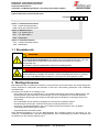
1
Bedienungs- und Installationsanleitung
Installation- and Operation Instruction
Fluidcontrolterminal FCT
mit Einfüll- und Belüftungsadapter / with filling and breather adapter
Lesen Sie die Bedienungsanleitung vor dem Gebrauch des Gerätes gründlich durch. Beachten Sie
insbesondere die Hinweise unter Gliederungspunkt 2. Andernfalls könnten Gesundheits- oder
Sachschäden auftreten. Die Bühler Technologies GmbH haftet nicht bei eigenmächtigen Änderungen des Gerätes oder für unsachgemäßen Gebrauch.
Read this instruction carefully prior to installation and/or use. Pay attention particularly to all
advice and safety instructions to prevent injuries. Bühler Technologies GmbH can not be held
responsible for misusing the product or unreliable function due to unauthorised modifications.
BX100006, 05/2014
Art. Nr. 903 1010
Bühler Technologies GmbH, Harkortstr. 29, D-40880 Ratingen
Tel. +49 (0) 21 02 / 49 89-0, Fax. +49 (0) 21 02 / 49 89-20
Internet: www.buehler-technologies.com
Email: [email protected]
1
Bedienungs- und Installationsanleitung
Installation- and Operation Instruction
Fluidcontrolterminal FCT
mit Einfüll- und Belüftungsadapter / with filling and breather adapter
Inhaltsverzeichnis
1
1.1
2
2.1
3
3.1
3.2
3.3
3.4
4
4.1
4.2
4.3
5
5.1
5.2
6
6.1
Seite
Einleitung ........................................................................................................................... 4
Einsatzbereich ...................................................................................................................................5
Wichtige Hinweise ............................................................................................................. 5
Allgemeine Hinweise .........................................................................................................................6
Montage.............................................................................................................................. 8
Elektrischer Anschluss des Niveauschalters .....................................................................................8
Elektrischer Anschluss des Unterdruckschalters ........................................................................... 10
Probenahmeanschluss ................................................................................................................... 10
Anschluss Befüllkupplung .............................................................................................................. 10
Betrieb .............................................................................................................................. 10
Niveauschalter ................................................................................................................................ 10
Probeentnahme .............................................................................................................................. 10
Befüllung......................................................................................................................................... 11
Wartung ............................................................................................................................ 11
Filterwechsel................................................................................................................................... 11
Entsorgung ..................................................................................................................................... 11
Instandsetzung ................................................................................................................ 12
Service und Reparatur ................................................................................................................... 12
7
Beigefügte Dokumente .................................................................................................... 12
8
Anhang ............................................................................................................................. 22
8.1
8.2
8.3
2
Tabelle Luftdurchsatz / Staudruck .................................................................................................. 22
Technische Daten .......................................................................................................................... 23
Abmessungen................................................................................................................................. 24
BX100006, 05/2014
Art. Nr. 903 1010
Bedienungs- und Installationsanleitung
Installation- and Operation Instruction
Fluidcontrolterminal FCT
mit Einfüll- und Belüftungsadapter / with filling and breather adapter
Contents
1
1.1
2
2.1
3
3.1
3.2
3.3
3.4
4
4.1
4.2
4.3
5
5.1
5.2
6
6.1
Page
Introduction ..................................................................................................................... 13
Intended use ....................................................................................................................................14
Important advice ............................................................................................................. 14
General indication of risk .................................................................................................................15
Assembly ......................................................................................................................... 17
Electrical connection of the level switch ..........................................................................................17
Electrical connection of the vacuum switch ....................................................................................19
Sample probe ..................................................................................................................................19
Filling port ........................................................................................................................................19
Operation ......................................................................................................................... 19
Level switches .................................................................................................................................19
Taking samples ...............................................................................................................................19
Filling ...............................................................................................................................................20
Maintenance .................................................................................................................... 20
Replacing the filter element .............................................................................................................20
Disposal ...........................................................................................................................................20
Servicing .......................................................................................................................... 21
Service and repair ...........................................................................................................................21
7
Attached documents ....................................................................................................... 21
8
Appendix ......................................................................................................................... 22
8.1
8.2
8.3
Diagram flow / differential pressure .................................................................................................22
Technical data .................................................................................................................................23
Dimensions ......................................................................................................................................24
BX100006, 05/2014
Art. Nr. 903 1010
3
Bedienungs- und Installationsanleitung
Installation- and Operation Instruction
Fluidcontrolterminal FCT
mit Einfüll- und Belüftungsadapter / with filling and breather adapter
1 Einleitung
Der konstruktive Aufbau des Fluidcontrolterminals erlaubt eine flexible Ausstattung, wodurch sich das
Gerät einfach an die Anforderungen der individuellen Applikation anpassen lässt. Platzbedarf und
Montageaufwand sind minimal. Das Fluidcontrolterminal besteht aus einem kompakten Adapter-Flansch
mit Anschlussbild nach DIN 24557-Teil 2, der Anschlussmöglichkeiten für eine Befüllkupplung, einen
Unterdruckschalter und einen Probenahmeanschluss bietet. Ein Niveau- und Temperaturschalter mit
Belüftungsfilter wird integriert. Das FCT wird direkt auf dem Tank montiert.
Je nach Bedarf können unterschiedliche Befüllkupplungen, Verschmutzungsanzeigen und Probenahmeanschlüsse angebaut werden. Die folgende Abbildung zeigt das Fluidcontrolterminal mit den
Bestückungsoptionen.
5
4a
H
4
3
2
2
4
56
1
4
2a
2b
3,5
50
L
180
4b
1) Flansch mit Anschlussmöglichkeiten
4) Befüllanschluss
2) Probenahmeanschluss
4a) Befüllanschluss Typ Walther (optional)
2a) Minimess (optional)
4b) Befüllanschluss Typ Stäubli mit Reduzierstutzen
G3/4 auf G1/2 (optional)
2b) Schlauchkupplung mit Einsteckhülle (optional)
5) Anschluss für Unterdruckschalter (optional)
3) Niveau- und Temperaturschalter mit
Belüftungsfilter
4
BX100006, 05/2014
Art. Nr. 903 1010
Bedienungs- und Installationsanleitung
Installation- and Operation Instruction
Fluidcontrolterminal FCT
mit Einfüll- und Belüftungsadapter / with filling and breather adapter
Typenschlüssel für Fluidcontrolterminal
FCT-G3/4 -
-
-
-
Länge (max. 1420 mm)
Option 1: Probenahme Anschluss
PSK Schlauchkupplung (DN 5)
PMM Minimess-Anschluss (M16)
Option 2: Befüllanschluss
BWA Typ: Walther DN 19
BST Typ: Stäubli DN 11
BBS Blindstopfen
Option 3: Unterdruckschalter
VUS Unterdruckschalter (elektr.)
VBS Blindstopfen
1.1 Einsatzbereich
WARNUNG
Alle Gerätetypen sind ausschließlich für industrielle Anwendungen vorgesehen. Es handelt
sich nicht um Sicherheitsbauteile. Die Geräte dürfen nicht eingesetzt werden, wenn bei
ihrem Ausfall oder bei Fehlfunktion die Sicherheit und Gesundheit von Personen
beeinträchtigt wird.
Der Einsatz in explosionsgefährdeten Bereichen ist nicht gestattet.
GEFAHR
Explosionsgefahr bei Verwendung in Explosionsgefährdeten Bereichen
Das Betriebsmittel ist nicht für den Einsatz in explosionsgefährdeten Bereichen geeignet.
Durch das Gerät dürfen keine zündfähigen oder explosiven Stoffe geleitet werden.
2 Wichtige Hinweise
Bitte überprüfen Sie vor Einbau des Gerätes, ob die genannten technischen Daten den Anwendungsparametern entsprechen. Überprüfen Sie ebenfalls, ob alle zum Lieferumfang gehörenden Teile vollständig
vorhanden sind.
Der Einsatz der Geräte ist nur zulässig, wenn
- das Produkt unter den in der Bedienungs- und Installationsanleitung beschriebenen Bedingungen, dem
Einsatz gemäß Typenschild und für Anwendungen, für die es vorgesehen ist, verwendet wird. Bei
eigenmächtigen Änderungen des Gerätes ist die Haftung durch die Bühler Technologies GmbH ausgeschlossen.
- die im Datenblatt und der Anleitung angegebenen Grenzwerte eingehalten werden.
- Überwachungsvorrichtungen / Schutzvorrichtungen korrekt angeschlossen sind.
- die Service- und Reparaturarbeiten, die nicht in dieser Anleitung beschrieben sind, von Bühler
Technologies GmbH durchgeführt werden.
- Originalersatzteile verwendet werden.
Diese Bedienungsanleitung ist Teil des Betriebsmittels. Der Hersteller behält sich das Recht vor, die
Leistungs-, die Spezifikations- oder die Auslegungsdaten ohne Vorankündigung zu ändern. Bewahren Sie
die Anleitung für den späteren Gebrauch auf.
BX100006, 05/2014
Art. Nr. 903 1010
5
Bedienungs- und Installationsanleitung
Installation- and Operation Instruction
Fluidcontrolterminal FCT
mit Einfüll- und Belüftungsadapter / with filling and breather adapter
In dieser Anleitung werden folgende Warnzeichen und Signalwörter benutzt:
Warnung vor einer allgemeinen Gefahr
Netzstecker ziehen
Warnung vor dem Einatmen giftiger Gase
Atemschutz tragen
Warnung vor ätzenden Flüssigkeiten
Gesichtsschutz tragen
Warnung vor explosionsgefährdeten Bereichen
Handschuhe tragen
Signalwörter für Warnhinweise:
HINWEIS
Signalwort für wichtige Information zum Produkt, auf die im besonderen Maße
aufmerksam gemacht werden soll.
VORSICHT
Signalwort zur Kennzeichnung einer Gefährdung mit geringem Risiko, die zu einem
Sachschaden oder leichten bis mittelschweren Verletzungen führen kann, wenn sie nicht
vermieden wird.
WARNUNG
Signalwort zur Kennzeichnung einer Gefährdung mit mittlerem Risiko, die möglicherweise Tod oder schwere Verletzungen zur Folge hat, wenn sie nicht vermieden wird.
GEFAHR
Signalwort zur Kennzeichnung einer Gefährdung mit hohem Risiko, die unmittel¬bar Tod
oder schwere Verletzung zur Folge hat, wenn sie nicht vermieden wird.
2.1 Allgemeine Hinweise
Das Gerät darf nur von Fachpersonal installiert werden, das mit den Sicherheitsanforderungen und den
Risiken vertraut ist.
Beachten Sie unbedingt die für den Einbauort relevanten Sicherheitsvorschriften und allgemein gültigen
Regeln der Technik. Beugen Sie Störungen vor und vermeiden Sie dadurch Personen- und Sachschäden.
Der für die Anlage Verantwortliche muss sicherstellen, dass:
- Sicherheitshinweise und Betriebsanleitungen verfügbar sind und eingehalten werden,
- Unfallverhütungsvorschriften der Berufsgenossenschaften beachtet werden; in Deutschland:
BGV A1: Grundsätze der Prävention und BGV A3: Elektrische Anlagen und Betriebsmittel,
- die zulässigen Daten und Einsatzbedingungen eingehalten werden,
- Schutzeinrichtungen verwendet werden und vorgeschriebene Wartungsarbeiten durchgeführt werden,
- bei der Entsorgung die gesetzlichen Regelungen beachtet werden.
Wartung, Reparatur:
- Reparaturen an den Betriebsmitteln dürfen nur von Bühler autorisiertem Personal ausgeführt werden.
- Nur Umbau-, Wartungs- oder Montagearbeiten ausführen, die in dieser Bedienungs- und Installationsanleitung beschrieben sind.
- Nur Original-Ersatzteile verwenden.
Bei Durchführung von Wartungsarbeiten jeglicher Art müssen die relevanten Sicherheits- und Betriebsbestimmungen beachtet werden.
6
BX100006, 05/2014
Art. Nr. 903 1010
Bedienungs- und Installationsanleitung
Installation- and Operation Instruction
Fluidcontrolterminal FCT
mit Einfüll- und Belüftungsadapter / with filling and breather adapter
GEFAHR
Elektrische Spannung
Gefahr eines elektrischen Schlages.
Trennen Sie das Gerät vor Beginn der Wartungsarbeiten vom Netz. Sichern
Sie das Gerät gegen unbeabsichtigtes Wiedereinschalten.
Anschluss und Wartung dürfen nur von geschultem Fachpersonal
vorgenommen werden. Achten Sie auf die korrekte Spannungsversorgung!
GEFAHR
Giftige, ätzende Medien
Verwendete Medien können gesundheitsgefährdend sein.
Schützen Sie sich bei der Wartung vor giftigen / ätzenden Gasen. Tragen Sie
die entsprechende Schutzausrüstung.
GEFAHR
Explosionsgefahr bei Verwendung in Explosionsgefährdeten Bereichen
Das Betriebsmittel ist nicht für den Einsatz in explosionsgefährdeten
Bereichen geeignet.
Durch das Gerät dürfen keine zündfähigen oder explosiven Gasgemische
geleitet werden.
BX100006, 05/2014
Art. Nr. 903 1010
7
Bedienungs- und Installationsanleitung
Installation- and Operation Instruction
Fluidcontrolterminal FCT
mit Einfüll- und Belüftungsadapter / with filling and breather adapter
3 Montage
Das Fluidcontrolterminal bzw. der Einfüll- und Belüftungsadapter wird komplett montiert angeliefert und
kann mittels der mitgelieferten Schrauben und Dichtungen auf dem Behälter befestigt werden.
Bei der Montage ist zu beachten, dass genügend Abstand zur Behälterwandung und Einbauten
eingehalten wird.
Durch das Befestigungslochbild nach DIN 24557 Teil 2 mit 6 Befestigungslöchern ist ein Einbau um jeweils
60 °C gedreht möglich. Sollten Sie eine Einheit mit Befüllkupplung und/oder Minimessanschluss bzw.
Schlauchkupplung haben, ordnen Sie diese so an, dass ein freier Zugang zu diesen Bauteilen jederzeit
gewährleistet ist.
6
ø60
ø73
ø90
6x
ø
Flansch
3.1 Elektrischer Anschluss des Niveauschalters
Das Gerät darf nur von autorisiertem Fachpersonal installiert werden, das mit den
Sicherheitsanforderungen und den Risiken vertraut ist.
Beachten Sie unbedingt die für den Einbauort relevanten Sicherheitsvorschriften und allgemein gültigen
Regeln der Technik.
Achten Sie auf die Einhaltung der im Datenblatt, der Bedienungsanleitung und dem Typenschild
angegebenen Daten.
GEFAHR
Elektrische Spannung
Gefahr eines elektrischen Schlages.
Trennen Sie das Gerät vor Beginn der Wartungsarbeiten vom Netz. Sichern
Sie das Gerät gegen unbeabsichtigtes Wiedereinschalten.
Anschluss und Wartung dürfen nur von geschultem Fachpersonal
vorgenommen werden. Achten Sie auf die korrekte Spannungsversorgung!
HINWEIS
!
Falsche Netzspannung kann das Gerät zerstören.
Bei Anschluss auf die richtige Netzspannung gemäß Typenschild achten.
Die Informationen zum Anschluss des
Bedienungsanleitung des Niveauschalters.
8
Niveauschalters
BX100006, 05/2014
entnehmen
Art. Nr. 903 1010
Sie
der
beigefügten
Bedienungs- und Installationsanleitung
Installation- and Operation Instruction
Fluidcontrolterminal FCT
mit Einfüll- und Belüftungsadapter / with filling and breather adapter
Hinweise zum korrekten Betrieb von Reedkontakten in Bühler Niveauschaltern
Reedkontakte sind konstruktionsbedingt sehr langlebige und zuverlässige Bauteile. Trotzdem sollte beim
Einsatz folgendes beachtet werden:
Lebensdauer von Reedschaltern
9
Die Lebensdauer von Reedschaltern kann bis zu 10 Schaltspiele betragen. Sie wird vermindert durch
hohe Belastung und / oder falsche oder nicht vorhandene Schutzbeschaltung beim Schalten von
induktiven, kapazitiven oder Lampenlasten.
Deswegen ist sicherzustellen, dass NIEMALS, auch nicht kurzzeitig, einer oder mehrere der
maximal zulässigen Grenzwerte überschritten werden und dass bei nicht rein ohmschen Lasten
eine Kontaktschutzbeschaltung angebracht wird. Auch die Anwendung von Prüflampen bei der
Installation der Geräte ist nicht zulässig, da durch diese kurzfristig ein zu hoher Strom fließen kann,
welcher die Reedkontakte beschädigen kann. Hier sollte man auf jeden Fall leistungslose Prüfmittel
verwenden.
Kontaktschutzbeschaltungen für Reedschalter
Bei Gleichspannung sollte eine Freilaufdiode nach Bild A parallel zum Kontakt angeschlossen werden.
Bei Wechselspannung sollte ein R-C Glied nach Bild B und Tabelle 1 parallel zum Kontakt angeschlossen
werden.
A
+
B
Kontakt
Kontakt
~
~
Last
_
R
C
RC-Glied
Schutzdiode
VA
Spannung am Kontakt V
24
48
110
230
10
R/Ohm
22
120
470
470
25
C/µF
0,022
0,0047
0,001
0,001
Last
R/Ohm
1
22
120
470
50
C/µF
0,1
0,022
0,0047
0,001
R/Ohm
1
1
22
120
75
C/µF
0,47
0,1
0,022
0,0047
R/Ohm
1
1
22
120
100
C/µF
1,0
0,47
0,047
0,022
R/Ohm
1
1
22
120
C/µF
1,0
0,47
0,1
0,022
Spannungen und Ströme
Alle Bühler Niveaukontakte mit Reedschaltern können minimale Schaltspannungen von 10 µV und
minimale Schaltströme von 1 µA schalten.
Es gelten die bei den jeweiligen Kontakttypen angegebenen Maximalwerte.
Darum können Niveaukontakte mit Reedschaltern bedenkenlos sowohl für SPS Anwendungen als auch für
hohe Belastungen (im Rahmen der Maximalgrenzwerte) eingesetzt werden.
Kontaktmaterial
Bei allen Reedschaltern in Bühler Niveaukontakten wird Rhodium als Kontaktmaterial im Bereich der
eigentlichen Kontaktflächen verwendet. Rhodium hat im Vergleich zu Gold eine erheblich höhere
Verschleißfestigkeit gegenüber Kontaktfunken und neigt auch weniger zum Verbrennen und Kleben der
Kontaktzungen. Gold wird ausschließlich als Trägermaterial für die nachfolgende Rhodiumschicht benutzt.
Der Übergangswiderstand der Kontaktflächen mit Rhodiumbeschichtung im Vergleich zu Goldbeschichtung
ändert sich nicht. Wegen der unbestreitbaren Vorteile der Rhodiumbeschichtung im Bereich der
Kontaktflächen, gibt es bereits seit Jahren bei keinem Reedschalterhersteller mehr Kontakte mit
Goldbeschichtung.
BX100006, 05/2014
Art. Nr. 903 1010
9
Bedienungs- und Installationsanleitung
Installation- and Operation Instruction
Fluidcontrolterminal FCT
mit Einfüll- und Belüftungsadapter / with filling and breather adapter
3.2 Elektrischer Anschluss des Unterdruckschalters
1
F000343X
Technische Daten: Anschlussdiagramm
Überdrucksicher bis : 0,1 bar
Schutzart
: IP 54 – mit Schutzkappe
Anzeigedruck
: -50 mbar ± 4
elektrische - : AMP 6,3 DIN 46248
Anschlüsse
für Steckhülse nach
Kontaktart
: Schließer
DIN 46247
Schaltleistung
: 24 V / 6 W *
Schaltungsart : 2-polig
* bei ohmscher Belastung
2
Es kann optional ein Unterdruckschalter oder ein Blindstopfen eingeschraubt sein.
Der Unterdruckschalter ist mit einem Sprungschalter ausgerüstet, um Signale nur dann zu schalten, wenn
die Grenzwerte voll und dauernd anliegen.
Beim Einfüll- und Belüftungsadapter bedarf nur der Unterdruckschalter einer elektrischen Inbetriebnahme.
3.3 Probenahmeanschluss
Minimessanschluss G1/8 mit Schraubkappe M16x2 oder Schlauchkupplung DN5 mit Einsteckschlauchtülle.
Dieser Anschluss dient als Ölprobeentnahme und benötigt in der Regel keine besondere Wartung. Achten
Sie lediglich beim Anschließen auf eine leckagefreien Anschluss und freien Zugang.
3.4 Anschluss Befüllkupplung
Befüllkupplung vom Typ Walter (DN 19) bzw. Stäubli (DN 11) oder Blindstopfen. Dieser Anschluss dient als
Befüllanschluss. Auch hier gelten die gleichen Hinweise wie für den Probenahmeanschluss.
4 Betrieb
4.1 Niveauschalter
Folgende Niveauschalter stehen für das Fluidcontrolterminal zur Verfügung:
NV 77 / NV 77D
NV 74 / NV 74D
NV 73
NV 71
Weitere Informationen zum eingebauten Niveauschalter entnehmen Sie bitte der beigefügten Bedienungsund Installationsanweisung zum Niveauschalter.
4.2 Probeentnahme
Um sicher zu stellen, dass das Fluid noch seine ursprünglichen Gebrauchseigenschaften besitzt und weiterhin allen Betriebsbelastungen gewachsen ist, ist die regelmäßige Entnahme einer Flüssigkeitsprobe zu
Analysezwecken sinnvoll.
Je nach Konfiguration ist die Entnahmestelle mit Schnellkupplungen oder Minimesskupplungen ausgerüstet. Zur Probenentnahme wird eine Handpumpe mit entsprechendem Kupplungsgegenstück benötigt.
Wird die Minimesskupplung verwendet empfehlen wir, das Kupplungsstück der Pumpe mit einem Querschlitz zu modifizieren. Diese Maßnahme erweitert den Ansaugquerschnitt und erleichtert das Abpumpen
erheblich.
Durch die Eintauchtiefe des Terminals ist der Entnahmepunkt fixiert, tiefenbedingte Messfehler sind dadurch ausgeschlossen. Achten Sie auf sauberes Besteck und gereinigte Probenflaschen zur verlässlichen
Entnahme.
Bei der Probeentnahme kann es vorkommen, dass sich noch Restmengen älteren Öles im Rohr befinden.
In diesem Fall sollte eine zweite Ölprobe entnommen werden.
10
BX100006, 05/2014
Art. Nr. 903 1010
Bedienungs- und Installationsanleitung
Installation- and Operation Instruction
Fluidcontrolterminal FCT
mit Einfüll- und Belüftungsadapter / with filling and breather adapter
4.3 Befüllung
Für die Befüllung stehen zwei Anschlusstypen zur Verfügung: ein Befüllnippel der Firma Stäubli (Abb. 1)
und eine Befüllkupplung der Firma Walther (Abb. 2). Über diese Befüllanschlüsse kann Öl manuell nachgefüllt werden.
82
64,5
14
Ø54
G3/4
ø33,5
G1/2
17
Abb. 1: Stäubli SBA 11/CN (Befüllnippel) mit
Reduzierstutzen G3/4 auf G1/2
83
20
Abb. 2: Walther MD-019 (Befüllkupplung)
5 Wartung
5.1 Filterwechsel
DANGER
Giftige, ätzende Medien
Verwendete Medien können gesundheitsgefährdend sein.
Schützen Sie sich bei der Wartung vor giftigen / ätzenden Gasen. Tragen Sie
die entsprechende Schutzausrüstung.
Die Wartung beschränkt sich auf den Wechsel des Filterelementes im Belüftungsfilter. Dieser muss bei
Bedarf, mindestens 1x jährlich ersetzt werden. Die genaue Anleitung dazu finden Sie in der Bedienungsund Installationsanweisung des jeweiligen Niveauschalters.
Entsorgen Sie das gebrauchte Filterelement nach den örtlichen Vorschriften.
5.2 Entsorgung
Bei der Entsorgung sind die gesetzlichen Vorschriften des Anwenderlandes zu beachten, insbesondere die
Vorschriften für die Entsorgung von elektronischen Bauteilen, gebrauchten Filterelementen usw.
BX100006, 05/2014
Art. Nr. 903 1010
11
Bedienungs- und Installationsanleitung
Installation- and Operation Instruction
Fluidcontrolterminal FCT
mit Einfüll- und Belüftungsadapter / with filling and breather adapter
6 Instandsetzung
6.1 Service und Reparatur
Sollte ein Fehler beim Betrieb auftreten, wenden Sie sich bitte an unseren Service
Tel.: +49-(0)2102-498955 oder Ihre zuständige Vertretung. Halten Sie dazu bitte die Daten des Typenschildes bereit.
Ist nach Beseitigung eventueller Störungen und nach Einschalten der Netzspannung die korrekte Funktion
nicht gegeben, muss das Gerät durch den Hersteller überprüft werden. Bitte senden Sie das Gerät zu
diesem Zweck in geeigneter Verpackung an:
Bühler Technologies GmbH
- Reparatur/Service Harkortstraße 29
40880 Ratingen
Deutschland
Bringen Sie zusätzlich die Dekontaminierungserklärung ausgefüllt und unterschrieben an der Verpackung
an. Ansonsten ist eine Bearbeitung Ihres Reparaturauftrages nicht möglich! Das Formular kann per E-Mail
angefordert werden: [email protected].
7 Beigefügte Dokumente
Konformitätserklärung
Dekontaminierungserklärung
12
KX 10 0024
BX100006, 05/2014
Art. Nr. 903 1010
Bedienungs- und Installationsanleitung
Installation- and Operation Instruction
Fluidcontrolterminal FCT
mit Einfüll- und Belüftungsadapter / with filling and breather adapter
1 Introduction
The design of the Fluidcontrolterminal provides highly flexible configurations allowing easy adoption to the
requirements of the application. The FCT is easy to assemble and needs only small installation space. It
consists of a compact adapter flange with hole pattern according to DIN 24557, Part 2 which provides
connections for a filling adapter, an vacuum switch and a sample probe. A level- and temperature switch
with air breather filter is integrated. The FCT is mounted directly to the tank top.
Depending on the application, different filling adapters, capacity sensors and sample probe connectors can
be mounted. The following figure shows the Fluidcontrolterminal with options.
5
4a
H
4
3
2
2
4
56
1
4
2a
2b
3,5
50
L
180
4b
1) Flange with connectors
4) Filling port
2) Sample port
4a) Filling port type Walther DN 19 (option)
2a) Minimess coupling (option)
4b) Filling port type Stäubli with reducing union G3/4
to G1/2 (option)
2b) Hose coupling with nozzle (option)
5) Connector for vacuum switch (option)
3) Level and temperature switch with air
breather filter
BX100006, 05/2014
Art. Nr. 903 1010
13
Bedienungs- und Installationsanleitung
Installation- and Operation Instruction
Fluidcontrolterminal FCT
mit Einfüll- und Belüftungsadapter / with filling and breather adapter
Product code for Fluidcontrolterminal
FCT-G3/4 -
-
-
-
-
Length (max 1420 mm)
Option 1: sample probe
PSK hose coupling with nozzle (DN 5)
PMM Minimess connector (M16)
Option 2: filling port
BWA Type: Walther DN 19
BST Type: Stäubli DN 11
BBS plug
Option 3: vacuum switch
VUS vacuum switch (electr.)
VBS plug
1.1 Intended use
WARNING
All types of devices are designed for industrial applications only. They are not designed as
safety devices. They must not be used if in case of failure or malfunction safety or health of
persons is affected.
The device is not suitable for use in hazardous areas with potentially explosive
atmosphere.
DANGER
Explosion hazard if used in hazardous areas
The device is not suitable for operation in hazardous areas with potentially explosive
atmospheres.
Do not expose the device to combustible or explosive substances.
2 Important advice
Please check prior to installation of the device that the technical data matches the application parameters.
Check that the delivery is complete as well.
Operation of the device is only valid if
- the product is used under the conditions described in the installation- and operation instruction, the
intended application according to the type plate and the intended use. In case of unauthorized
modifications done by the user Bühler Technologies GmbH can not be held responsible for any
damage,
- the performance limits given in the datasheets and in the installation- and operation instruction are
obeyed,
- monitoring devices and safety devices are installed properly,
- service and repair is carried out by Bühler Technologies GmbH, unless described in this manual,
- only original spare parts are used.
This manual is part of the equipment. The manufacturer keeps the right to modify specifications without
advanced notice. Keep this manual for later use.
14
BX100006, 05/2014
Art. Nr. 903 1010
Bedienungs- und Installationsanleitung
Installation- and Operation Instruction
Fluidcontrolterminal FCT
mit Einfüll- und Belüftungsadapter / with filling and breather adapter
The following warning signs and signal words are used in this manual:
Warning against
hazardous situation
Warning against possible
explosive atmospheres
disconnect from
mains
Warning against
electrical voltage
Warning against hot
surface
wear respirator
Warning against
respiration of toxic gases
wear face
protection
Warning against acid
and corrosive
substances
wear gloves
Signal words for warnings:
NOTE
Signal word for important information to the product
CAUTION
Signal word for a hazardous situation with low risk, resulting in damage to the device or
the property or minor or medium injuries if not avoided.
WARNING
Signal word for a hazardous situation with medium risk, possibly resulting in severe
injuries or death if not avoided.
DANGER
Signal word for an imminent danger with high risk, resulting in severe injuries or death if
not avoided
2.1 General indication of risk
Installation of the device shall be performed by trained staff only, familiar with the safety requirements and
risks.
Adhere to all relevant safety regulations and technical indications for the specific installation place. Prevent
failures and protect persons against injuries and the device against damage.
The person responsible for the system must secure that:
- safety and operation instructions are accessible and followed,
- local accident prevention regulations and standards are obeyed,
- performance data and installation specifications are regarded,
- safety devices are installed and recommended maintenance is performed,
- national regulations for disposal of electrical equipment are obeyed.
Maintenance and repair
- Repairs on the device must be carried out by Bühler authorized persons only.
- Only perform modifications, maintenance or mounting described in this manual.
- Only use original spare parts.
During maintenance regard all safety regulations and internal operation instructions.
BX100006, 05/2014
Art. Nr. 903 1010
15
Bedienungs- und Installationsanleitung
Installation- and Operation Instruction
Fluidcontrolterminal FCT
mit Einfüll- und Belüftungsadapter / with filling and breather adapter
DANGER
Electrical voltage
Electrocution hazard.
Before opening the cover or working on electrical components, disconnect the
device from power supply. Make sure that the equipment cannot be
reconnected to mains unintentionally.
Installation and maintenance must be carried out by trained staff only. Regard
correct mains supply.
DANGER
Toxic and corrosive gases
Used Substances can be hazardous.
Protect yourself during maintenance against toxic / corrosive gases. Use
gloves, respirator and face protector under certain circumstances.
DANGER
Explosion hazard if used in hazardous areas
The device is not suitable for operation in hazardous areas with potentially
explosive atmospheres.
Do not expose the device to combustible or explosive gas mixtures.
16
BX100006, 05/2014
Art. Nr. 903 1010
Bedienungs- und Installationsanleitung
Installation- and Operation Instruction
Fluidcontrolterminal FCT
mit Einfüll- und Belüftungsadapter / with filling and breather adapter
3 Assembly
The Fluidcontrolterminal and the filling and breather adapter are supplied completely assembled and ready
for installation. Use the attached gaskets and bolts for mounting. Make sure that the stilling tube has no
contact with obstacles. The mounting hole according to DIN 24557 part 2 with 6 screw-holes enables
mounting in steps of 60°.
If you have a unit with filling port and/or additional test point outlet or hose coupling take care that you have
a free access to this parts after mounting.
ø6
(
0.2
)
ø73 (2.9)
ø60 (2.4)
ø90 (3.5)
6x
flange
3.1 Electrical connection of the level switch
The device must be installed by authorized trained staff only, familiar with the safety requirements and
risks.
Check all relevant safety regulations and technical indications for the specific installation place.
Regard performance limits and technical specifications given in the data sheet, this manual, and the type
plate.
Prevent failures and protect persons against injuries and the device against damage.
DANGER
Electrical voltage
Electrocution hazard.
Before opening the cover or working on electrical components, disconnect the
device from power supply. Make sure that the equipment cannot be
reconnected to mains unintentionally.
Installation and maintenance must be carried out by trained staff only. Regard
correct mains supply.
!
NOTE
Wrong mains voltage may destroy the device.
Regard the correct mains supply as given on the type plate.
Please find the information for connecting the level switch in the attached Installation and operation manual
of the respective level switch.
BX100006, 05/2014
Art. Nr. 903 1010
17
Bedienungs- und Installationsanleitung
Installation- and Operation Instruction
Fluidcontrolterminal FCT
mit Einfüll- und Belüftungsadapter / with filling and breather adapter
Information on the correct operation of reed contacts in Bühler level switches
Based on their construction, reed contacts are very long lasting and reliable components. Yet the following
should be considered when using them:
Life of reed switches
9
The life of reed switches reed switches can be up to 10 cycles. This is reduces by high stress and / or
incorrect or the absence of protective circuits when switching inductive, capacitive or lamp loads.
It’s therefore important to ensure NEVER to exceed one or several of the maximum approved limits,
even temporarily, and to install a contact protective circuit for loads which are not purely ohmic.
Using test lamps when installing the devices is also prohibited, as these can temporarily allow too
much current to flow, which can damage the reed contacts. In this case non-volatile testing
equipment should always be used.
Contact protective circuits for reed switches
Under direct current voltage a recovery diode per figure A should be connected parallel to the contact.
Under alternating current voltage an RC circuit per Figure B and Table 1 should be connected parallel to
the contact.
A
+
B
contact
contact
~
~
load
_
R
C
RC-network
Diode
VA
Voltage at contact V
24
48
110
230
10
R/Ohm
22
120
470
470
load
25
C/µF
0,022
0,0047
0,001
0,001
R/Ohm
1
22
120
470
50
C/µF
0,1
0,022
0,0047
0,001
R/Ohm
1
1
22
120
75
C/µF
0,47
0,1
0,022
0,0047
R/Ohm
1
1
22
120
100
C/µF
1,0
0,47
0,047
0,022
R/Ohm
1
1
22
120
C/µF
1,0
0,47
0,1
0,022
Voltages and currents
All Bühler level contacts with reed switch can switch minimal Switching voltages of 10 µV and minimal
switching currents of 1 µA.
The maximum values specified for the respective contact types apply.
Level contact with reed switches can therefore be used for SPS applications as well as for high loads
(within the maximum limits) without hesitation.
Contact material
All reed switches in Bühler level contacts use rhodium as the contact material for the actual contact areas.
Compared to gold, rhodium is significantly more wear resistant to contact sparks and the contact blades
are also less likely to burn and adhere. Gold is only used as a support material for the ensuing rhodium
layer. The contact resistance of rhodium coated contact areas is no different than gold coated. Based on
the undeniable advantages of rhodium coating for contact areas, reed switch manufacturers phased out
gold plated contacts years ago.
18
BX100006, 05/2014
Art. Nr. 903 1010
Bedienungs- und Installationsanleitung
Installation- and Operation Instruction
Fluidcontrolterminal FCT
mit Einfüll- und Belüftungsadapter / with filling and breather adapter
3.2 Electrical connection of the vacuum switch
As an option, a vacuum switch may be installed.
Low-pressure safety switches are provided with snap switches, which assures the signal is issued only
when the limit has been fully and permanently reached.
: normally open
: 24 V / 6 W
: IP 54 – with protecting cap
: AMP 6,3 DIN 46248,
DIN 46247
2-pol.
1
contact type
contact load
Protection class
electrical connections
F000343X
Technical data: wiring diagram
permissible over-pressure : max. 0,1 bar
indicator setting
: -50 mbar ± 4
2
At filling and breather adapter only the low-pressure safety switch have electrical connection (therefore see
data on next page).
3.3 Sample probe
The sample probe connection provides an outlet G1/8 thread with cap M16x2 or a hose coupling DN5 with
nozzle. This connection is used as an oil sample port. Normally these parts need no maintenance. Pay
attention only that you have a free access to this parts after mounting.
3.4 Filling port
The FCT provides a filling port with coupling type Walter (NW 19) or Stäubli (NW 11) or a sealing plug. This
port applies to the same clues as option 1.
4 Operation
4.1 Level switches
The following level switches are available for the Fluidcontrolterminal:
NV 77 / NV 77D
NV 74 / NV 74D
NV 73
NV 71
For further information, please refer to the installation and instruction manual of the build-in level and
temperature switch.
4.2 Taking samples
To ensure that the used fluid still has its recommended properties and withstand all operation loads the
fluid should be analyzed in regular intervals.
Depending on the configuration, the sample port is equipped with a quick coupling device or with Minimess
coupling. For taking samples, you need the respective counter piece.
If the Minimess is used, we recommend modifying the oil pumps coupling device with a transverse slot.
This enlarges the intake cross-section and makes pumping a lot easier.
Due to the fixed immersion depth of the Multiterminal, measuring errors resulting from taking samples at
different depth are eliminated. Make sure to use clean tools and collecting flasks.
When taking an oil sample it might be that there is old residual oil in the pipe, for this we advise to take a
second sampling.
BX100006, 05/2014
Art. Nr. 903 1010
19
Bedienungs- und Installationsanleitung
Installation- and Operation Instruction
Fluidcontrolterminal FCT
mit Einfüll- und Belüftungsadapter / with filling and breather adapter
4.3 Filling
For filling, two types of connection are provided: a Stäubli filling port (see Fig. 1) and a filling coupling. Both
ports allow refilling oil manually.
82
64,5
14
Ø54
G3/4
ø33,5
G1/2
17
Fig. 1: Stäubli SBA 11/CN (filling port)
with reducing union G3/4 to G1/2
83
20
Fig. 2: Walther MD-019 (filling coupling)
5 Maintenance
5.1 Replacing the filter element
DANGER
Toxic and corrosive media
Used Substances can be hazardous.
Protect yourself during maintenance against toxic / corrosive gases. Use
gloves, respirator and face protector under certain circumstances.
Maintenance is reduced to replacing the filter element of the air breather filter. It has to be replaced if
necessary, at least once a year. For instruction to replace the filter element please refer to the Installation
and operation manual of the respective level switch.
Dispose the used filter element according to local regulations.
5.2 Disposal
Regard the local regulations for disposal of electric and electronic equipment, used filter elements etc.
20
BX100006, 05/2014
Art. Nr. 903 1010
Bedienungs- und Installationsanleitung
Installation- and Operation Instruction
Fluidcontrolterminal FCT
mit Einfüll- und Belüftungsadapter / with filling and breather adapter
6 Servicing
6.1 Service and repair
If the device shows irregularities please contact our service department.
Call +49(0)2102-498955 or your local agent.
Please hold the data of the type plate ready.
If the device doesn’t work correctly after elimination of failures and turning power on, the device must be
checked by the manufacturer. Please ship the device with suitable packing to
Bühler Technologies GmbH
- Service Harkortstraße 29
40880 Ratingen
Germany
In Addition, attach the filled in and signed Declaration of Decontamination status to the packing. Otherwise,
your repair order cannot be processed! The form can be requested by e-mail to [email protected].
7 Attached documents
Declaration of Conformity
KX 10 0024
Declaration of Contamination status
BX100006, 05/2014
Art. Nr. 903 1010
21
Bedienungs- und Installationsanleitung
Installation- and Operation Instruction
Fluidcontrolterminal FCT
mit Einfüll- und Belüftungsadapter / with filling and breather adapter
8 Anhang
8 Appendix
8.1 Tabelle Luftdurchsatz /
Staudruck
8.1 Diagram flow / differential
pressure
Luftdurchsatz - Staudruck - Tabelle Fluidcontrolterminal
flow / differential pressure diagramm fluidcontrolterminal
110
100
90
80
mit SM-L Filter
with SM-L filter
m bar
70
60
50
40
mit MIC Filter
with MIC filter
30
20
10
0
0
120
240
360
480
600
720
840
960
1080 1200
l/min
22
BX100006, 05/2014
Art. Nr. 903 1010
Bedienungs- und Installationsanleitung
Installation- and Operation Instruction
Fluidcontrolterminal FCT
mit Einfüll- und Belüftungsadapter / with filling and breather adapter
8.2 Technische Daten
8.2 Technical data
Fluidcontrolterminal
Fluidcontrolterminal
Basis Daten
Basic data
Betriebsdruck max.
Betriebstemperatur max.
Maß L (mm)*
1 bar
Operating pressure max.
80 °C / 176 °F
280, 370, 500 (standard),
Variabel (max. 1420)
Gewicht
bei L = 500 mm
Flansch
Dimensions L (mm)*
Weight
~ 5 kg
at L = 500 mm
Material
Schwallschutzrohr
Operating temperature max.
Material
Messing / brass
Stilling tube
Stahl verzinkt / steel
Probenahme
Flange
Sample port
Schlauchkupplung (DN 5 )
PSK
Hose coupling (DN 5)
Minimessanschluss (M 16)
PMM
MINIMESS coupling (M 16)
Befüllkupplung
Typ Walther (DN 19)
Filling port
BWA
Type Walther (DN 19)
Typ Stäubli (DN 11)
BST
Type Stäubli (DN 11)
Blindstopfen
BBS
Plug
Unterduckanzeige
Clogging indicator
Unterdruckschalter (elektrisch)
VUS
Vacuum switch (electrical)
Blindstopfen
VBS
Plug
*Beachten Sie, dass das Maß L beim Befüllanschluss und beim ausgewähltem Niveauschalter gleich sein
muss!
*Please note that the dimensions L for filling port and selected level switch must match each other!
BX100006, 05/2014
Art. Nr. 903 1010
23
Bedienungs- und Installationsanleitung
Installation- and Operation Instruction
Fluidcontrolterminal FCT
mit Einfüll- und Belüftungsadapter / with filling and breather adapter
8.3 Abmessungen
8.3 Dimensions
Alle Angaben in mm / All dimensions given in mm
5
4a
H
3
3
4
2
4
56
1
4
2a
180
2b
3,5
50
L
4b
*
1) Flansch mit Anschlussmöglichkeiten
4) Befüllanschluss
2) Probenahmeanschluss
4a) Befüllanschluss Typ Walther (optional)
2a) Minimess (optional)
4b) Befüllanschluss Typ Stäubli (optional)
2b) Schlauchkupplung mit Einsteckhülle (optional)
5) Anschluss für Unterdruckschalter
3) Niveau- und Temperaturschalter mit
Belüftungsfilter
* H: abhängig vom eingesetzten Niveauschalter / depends on the installed level switch
24
6
Lochbild nach DIN 24557, Teil 2
Mounting pattern according to DIN 24557, Part 2
ø60
ø73
ø90
6x
ø
BX100006, 05/2014
Art. Nr. 903 1010
Dekontaminierungserklärung
Declaration of Contamination status
Gültig ab / valid since: 2011/05/01
Revision 0
ersetzt Rev. / replaces Rev ---
Die gesetzlichen Vorschriften schreiben vor, dass Sie uns die Dekontaminierungserklärung ausgefüllt und unterschrieben
zurück zu senden haben. Die Angaben dienen zum Schutz unserer Mitarbeiter. Bringen Sie die Bescheinigung an der
Verpackung an. Ansonsten ist eine Bearbeitung Ihres Reparaturauftrages nicht möglich!
Legal regulations prescribe that you have to fill in and sign the Declaration of Contamination status and send it back. This
information is used to protect our employees. Please attach the declaration to the packing. Otherwise, your repair
order cannot be processed.
Gerät /
Device:
Serien-Nr. /
Serial no. :
Rücksendegrund /
Reason for return:
[
]
Ich bestätige hiermit, dass das oben spezifizierte Gerät ordnungsgemäß gereinigt und dekontaminiert wurde
und keinerlei Gefahren im Umgang mit dem Produkt bestehen.
I herewith declare that the device as specified above has been properly cleaned and decontaminated and that
there are no risks present when dealing with the device.
Ansonsten ist die mögliche Gefährdung genauer zu beschreiben / In other cases, please describe the hazards in
detail:
Aggregatzustand (bitte ankreuzen) / Condition of aggregation (please check):
Flüssig / Liquid
Fest / Solid
Pulvrig / Powdery
Gasförmig / Gaseous
Folgende Warnhinweise sind zu beachten (bitte ankreuzen) / The following safety advices must be obeyed (please
check):
Explosiv
Explosives
Giftig / Tödlich
Acute toxicity
Entzündliche Stoffe
Flammable
Brandfördernd
Oxidizing
Komprimierte Gase
Gas under pressure
Gesundheitsgefährdend
Irritant toxicity
Gesundheitsschädlich
Health hazard
Umweltgefährdend
Environmental hazard
Bitte legen Sie ein aktuelles Datenblatt des Gefahrenstoffes bei / Please include the current material safety data sheet
of the hazardous material!
Angaben zum Absender / Information about the dispatcher:
Firma / Company:
Anschrift / Address:
Ansprechpartner /
Contact person:
Abteilung / Division:
E-Mail:
Tel. / Phone:
Fax:
Ort, Datum /
Location, date:
Unterschrift /
Stempel
Signature / Stamp:
Bühler Technologies GmbH
D - 40880 Ratingen, Harkortstr. 29
Tel.: + 49 (0) 2102 / 4989-0 Fax: + 49 (0) 2102 / 4989-20
e-mail: [email protected]
Internet: www.buehler-technologies.com