1
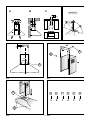
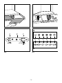
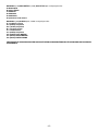
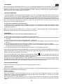
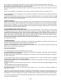
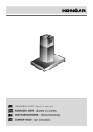
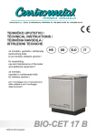
HR
SiCG
D
GB
KUHINJSKA NAPA - Upute za uporabu
KUHINJSKA NAPA - Uputstva za upotrebu
DUNSTABZUGSHAUBE - Gebrauchsanweiung
COOKER HOOD - User instructions
A
B
C
max 90 cm
M
20
SI.1
A
B
235
A
SI.2
SI.3
C
A
A
SI.4
- 2 - SI.5
B
C
D
E
F
90°
SI.7
SI.6
A
A
B
C
G
A1 A2
C1 C2 C4
C3
B
SI.8
SI.9
-3-
B
C
D
E
A
OPĆENITO
HR
Pažljivo pročitajte upute za postavljanje i održavanje. Upute čuvajte dostupnim za kasniju uporabu.
Aparat je izveden kao izvedba nape s ispuhom u ventilacijski kanal (zrak se ispuhuje van – sl.1B), izvedba s filtrima
(zrak cirkulira unutar prostorije – sl. 1A) ili s prisilnim ispuhom (vanjski motor- sl.1C).
SAVJETI ZA SIGURNU UPORABU
1. Istovremeni rad nape i aparata koji za svoj rad koriste zrak iz okoline ( npr. plamenici i plinski bojleri) nije
preporučljiv, budući da napa uzima zrak iz okoline koji treba plamenu za sagorijevanje.
Negativni tlak u okolini ne smije prelaziti 4 Pa (4 x 10⁻⁵ bar).
Osigurajte siguran rad nape pazeći pri tome da budu zadovoljeni lokalni propisi.
Prije spajanja uzorka na el. mrežu:
-prekontrolirajte natpisnu pločicu (postavljenu unutar aparata) i utvrdite da li napon i snaga odgovaraju mreži i da li
je utičnica odgovarajuća. Ako ste u dvojbi pitajte stručnu osobu.
Ako je priključni kabel oštećen, zamjenu oštećenog kabela mora obaviti stručno osposobljena osoba ili ovlašteni
serviser.
2. UPOZORENJE!!
U nekom okolnostima el. aparati mogu biti opasni.
A)
Ne provjeravajte stanje filtra dok napa radi.
B)
Ne dirajte žarulje ili susjedna područja, za vrijeme ili neposredno nakon dugotrajnog korištenja rasvjete.
C)
Flambiranje ispod nape je zabranjeno.
D)
Izbjegavajte otvoreni plamen, kako ne bi došlo do oštećenja filtra i požara.
E)
Stalno provjeravajte prženu hranu da bi izbjegli zapaljenje ulja.
F)
Isključite aparat iz el. instalacije prije bilo kakvog održavanja.
G)
Ovaj aparat nije namijenjen za korištenje maloj djeci i retardiranim osobama bez nadzora.
H)
Maloj djeci onemogućite pristup aparatu.
I)
Istovremeni rad nape i aparata koji za svoj rad koriste zrak iz okoline ( npr. plamenici i plinski bojleri) nije
preporučljiv, budući da napa uzima zrak iz okoline koji treba plamenu za sagorijevanje.
J)
Neodgovarajuće očišćeni aparati mogu prouzročiti požar.
UPUTE ZA POSTAVLJANJE
Priključenje na el. instalaciju treba obavljati stručno osposobljena osoba.
Priključenje na električnu instalaciju
Aparat je izveden u klasi II, tako da kabel za uzemljenje nije neophodan.
Priključni vod je izveden kako slijedi:
SMEĐA= L faza
PLAVA= N nula
Napa se priključuje na propisno instaliranu zidnu priključnicu. Ako se napa priključuje preko trajnog el. priključka trajni
el. priključak mora biti izveden preko sklopki za odvajanje svih polova od čvrste električne instalacije prema
nacionalnim propisima za izradu el. instalacije odgovarajućeg napona.
Minimalni razmak između površine na koju se oslanjaju posude za kuhanje i najnižeg dijela nape mora biti najmanje
65 cm.
Ako je odvodna cijev izvedena u dva dijela, gornji dio mora biti iznad donjeg dijela.
Za ispuhivanje koristite odgovarajući ventilacijski kanal na koji ne smiju biti spojeni uređaji koji ne rade na el. energiju.
Prije postupka postavljanja skinite filtar za masnoću (sl.6) tako da napu lakše pridržavate.
Kod izvedbe nape s ispuhom pripremite rupu za odvodnju zraka.
Postavljanje nape na zid
Izbušite rupe A u skladu s naznačenim kotama na sl.2.
Pričvrstite napu na zid i dovedite je u horizontalan položaj. Kad je aparat podešen pričvrstite ga do kraja vijcima A
(sl.4). Za montažu nape na zid koristite vijke i sidrene nastavke (tiple) za odgovarajući zid (npr.armirano-betonski,
gipsani).
Kada su vijci i tiple isporučeni pobrinite se da oni odgovaraju tipu zida na koji se montira napa.
Postavljanje ukrasnog teleskopskog dimnjaka
Uskladite dužinu priključnog voda s dimenzijama dekorativnog dimnjaka. Ako je vaš aparat u varijanti s ispuhom ili s
-4-
vanjskom motorom pripremite otvor za izlaz zraka. Podesite konzolu gornjeg dijela dimnjaka prema slici 3 i kotama na
slici 2. Spojite prirubnicu C na otvor za odvod zraka koristeći spojni prsten (sl.4). Umetnite gornji dio dimnjaka u donji
dio. Izvucite gornji dio do konzole u učvrstite ga s vijcima B (sl.3).
Kod preinačenja nape od izvedbe s ispuhom na izvedbu nape s filtrima , pitajte lokalne trgovce za filtre s aktivnim
ugljenom i zatim postupite prema uputama za montažu nape za izvedbu s filtrima.
Izvedba s filtrima
Postavite napu i dva nastavka dimnjaka kako je opisano u odjeljku montaže nape s ispuhom.
Montirajte filtar prema uputama isporučenim uz filtar.
Ako nisu (kit) isporučene, zatražite ih od lokalnog distributera.
Filtar se postavlja unutar nape i učvršćuje zakretanjem za 90 stupnjeva (sl.7).
UPORABA I ODRŽAVANJE
Preporuča se da se napa uključi prije kuhanja.
Preporuča se da se napa ostavi da radi 15 min nakon završetka kuhanja tako da u potpunosti nestanu isparenja i
mirisi kuhanja.
Pravilno funkcioniranje nape je uvjetovano redovitošću održavanja, osobito, filtra s aktivnim ugljenom.
Filtar protiv masnoće sakuplja čestice masnoće koje lebde u zraku i zbog toga je podložan začepljenju ovisno o
učestalosti korištenja aparata.
Kako bi spriječili opasna oštećenja preporuča se da se obavi čišćenje filtra maximalno za 2 mjeseca prema sljedećim
uputama:
-Skinite filtar s nape i operite ga u otopini vode i neutralnog tekućeg deterdženta, ostavljenog da se namoči.
-Temeljito isperite s toplom vodom i ostavite sa se osuši.
-Filtar se može prati i u perilici posuđa.
Aluminijski paneli (filtri) mogu promjeniti boju nakon nekoliko pranja. To nije razlog za reklamaciju korisnika niti za
zamjenu filtara.
Ugljeni filtar prečišćava zrak koji se mijenja (kruži) u okolini. Filtri nisu perivi niti ponovo upotrebljivi i moraju se
mijenjati maximalno svaka četiri mjeseca. Zasićenost ugljenog filtra ovisi od učestalosti korištenja aparata, od vrste
kuhanja i redovitosti čišćenja filtra protiv masnoće.
Redovito čistite ventilator i druge površine nape koristeći krpu namočenu u denaturirani alkohol ili neabrazivni tekući
deterdžent.
Instalacija rasvjete je napravljena za korištenje za vrijeme kuhanja i nije za dugotrajnu glavnu rasvjetu prostorije.
Dugotrajno korištenje rasvjete ponajprije smanjuje vijek trajanja žarulja.
NAREDBE: (sl.5) SVIJETLO i simboli na tipkama su objašnjeni niže:
A= SVIJETLO
B= ISKLJUČENO
C= BRZINA I
D= BRZINA II
E= BRZINA III
F= FUNKCIJA „ČISTI ZRAK“
Ako vaš aparat nema INTENZIVNU funkciju brzine, pritisnite tipku E dvije sekunde i biti će aktivirana na 10 minuta
nakon čega će se vratiti na predhodni izbor brzine.
Kada je funkcija aktivna lampica svijetli. Za nastavak prije nego istekne 10 min ponovno pritisnite tipku E.
Pritiskanjem tipke F na dvije sekunde (uz upaljenu tipku OFF) aktivira se funkcija “čisti zrak”. Ova funkcija uključuje
aparat na 10 minuta svaki sat pri prvoj brzini. Čim je funkcija uključena motor počinje raditi pri prvoj brzini, za to
vrijeme tika F i tipka C moraju istovremeno svijetliti.
Poslije deset minuta motor prestaje raditi, a lampica tipke F ostaje raditi s stalnom rasvjetom sve dok motor ponovo
ne počne raditi u prvoj brzini nakon pedeset minuta i tipka F i tipka C ponovno svijetle istovremeno narednih deset
minuta itd.
Pritiskom bilo koje tipke na napi napa će se odmah vratiti u normalnu funkciju. (npr. ako pritisnemo tipku D “čisti zrak”
je deaktiviran i motor radi dalje u drugoj brzini. Kad pritisnemo tipku B funkcija je deaktivirana.)
Aktivni ugljen / zasićenost filtra za masnoću:
-Kada tipka A svijetli s frekvencijom od dvije sekunde, filtar za masnoću mora se očistiti.
-Kada tipka A svijetli s frekvencijom od 0.5 sekundi, ugljeni filtar mora biti zamijenjen.
Poslije čišćenja i zamjene filtara, elektronička memorija mora biti restartana tako da tipku A držimo pritisnutu približno
5 sekundi, dok svijetlo na tipki prestane svijetliti.
-5-
NAREDBE:(sl.9A)MEHANIČKE, (sl.9B) ELIPTIČKE tipke su objašnjene niže:
A= RASVIJETA
B= ISKLJUČENO
C= BRZINA I
D= BRZINA II
E= BRZINA III
G= pokazivač rada motora
NAREDBE: (sl.8)KLIZNE tipke, simboli su objašnjeni niže:
A = prekidač rasvjete
A1= položaj isključeno
A2 = položaj uključeno
B = signalno svijetlo
C = naredba brzine
C1= položaj isključeno
C2= položaj PRVE BRZINE
C3= položaj DRUGE BRZINE
C4= položaj TREĆE BRZINE
PRIOZVOĐAČ NE ODGOVARA ZA EVENTUALNA OŠTEĆENJA PROUZROČENA NEPOŠTOVANJEM GORE NAVEDENIH
UPOZORENJA.
-6-
UOPŠTENO
SiCG
Pažljivo pročitajte uputstva za postavljanje i održavanje. Uputstva čuvajte dostupnim za kasniju upotrebu.
Aparat je izveden kao izvedba nape s ispuhivanjem u ventilacijski kanal (vazduh se ispuhuje van – sl.1B), izvedba
s filterima (vazduh cirkulira unutar prostorije – sl. 1A) ili s prisilnim ispuhivanjem(vanjski motor- sl.1C).
SAVETI ZA BEZBEDNU UPOTREBU
1. Istovremeni rad nape i aparata koji za svoj rad koriste vazduh iz okoline ( npr. gorionici i gasni bojleri) nije
preporučljiv, budući da napa uzima vazduh iz okoline koji treba plamenu za sagorevanje.
Negativan pritisak u okolini ne sme da prelaziti 4 Pa (4 x 10⁻⁵ bar).
Treba da obezbedite betbedan rad nape pazeći pri tome da budu zadovoljeni lokalni propisi.
Pre spajanja nape na el. mrežu:
-prekontrolirajte natpisnu pločicu (postavljenu unutar aparata) i utvrdite da li napon i snaga odgovaraju mreži i da li
je utičnica odgovarajuća. Ako ste u dvojbi pitajte stručno lice.
Ako je priključni kabel oštećen, zamjenu oštećenog kabela mora obaviti stručno osposobljeno lice ili ovlašteni
serviser.
2.
UPOZORENJE!!
U određenim okolnostima el. aparati mogu da budu opasni.
A)
Nemojte da proveravajte stanje filera dok napa radi.
B)
Nemojte da dirate sijalice i okolna područja, za vreme ili neposredno nakon dugotrajnog korištenja rasvete.
C)
Flambiranje ispod nape je zabranjeno.
D)
Izbegavajte otvoreni plamen, kako ne bi došlo do oštećenja filtera i požara.
E)
Stalno proveravajte prženu hranu da bi izbegli zapaljenje ulja.
F)
Isključite aparat iz el. instalacije pre bilo kakvog održavanja.
G)
Ovaj aparat nije namenjen za korištenje maloj deci i retardiranim licima bez nadzora.
H)
Maloj deci onemogućite pristup aparatu.
I)
Istovremeni rad nape i aparata koji za svoj rad koriste vazduh iz okoline ( npr. gorionici i gasni bojleri) nije
preporučljiv, budući da napa uzima vazduh iz okoline koji treba plamenu za sagorevanje.
J)
Neodgovarajuće očišćeni aparati mogu da prouzroče požar.
UPUTSTVO ZA POSTAVLJANJE
Priključenje na el. instalaciju treba da obavi stručno osposobljeno lice.
Priključenje na električnu instalaciju
Aparat je izveden u klasi II, tako da kabel za uzemljenje nije neophodan.
Priključni vod je izveden kako sledi:
SMEĐA= L faza
PLAVA= N nula
Napa se priključuje na propisno instaliranu zidnu priključnicu. Ako se napa priključuje preko stalnog el. priključka
stalni el. priključak mora da bude izveden preko sklopki za odvajanje svih polova od čvrste električne instalacije
prema nacionalnim propisima za izradu el. instalacije odgovarajućeg napona.
Minimalni razmak između površine na koju se oslanjaju posude za kuhanje i najnižeg dela nape mora da bude
najmanje 65 cm.
Ako je odvodna cev izvedena u dva dela, gornji dio mora biti iznad donjeg dela.
Za ispuhivanje koristite odgovarajući ventilacijski kanal na koji ne smeju da budu spojeni uređaji koji ne rade na el.
energiju.
Pre postupka postavljanja skinite filter za masnoću (sl.6) tako da napu lakše pridržavate.
Kod izvedbe nape s ispuhom pripremite rupu za odvodnju vazduha.
Postavljanje nape na zid
Izbušite rupe A u skladu s naznačenim kotama na sl.2.
Pričvrstite napu na zid i dovedite je u horizontalan položaj. Kad je aparat podešen pričvrstite ga do kraja vijcima A
(sl.4). Za montažu nape na zid koristite vijke i sidrene nastavke (tiple) za odgovarajući zid (npr.armirano-betonski,
gipsani).
Kada su vijci i tiple isporučeni pobrinite se da oni odgovaraju tipu zida na koji se montira napa.
Postavljanje ukrasnog teleskopskog dimnjaka
Uskladite dužinu priključnog voda s dimenzijama dekorativnog dimnjaka. Ako je vaš aparat u izvedbi s ispuhom ili s
-7-
vanjskim motorom pripremite otvor za izlaz vazduha. Podesite konzolu gornjeg dela dimnjaka prema slici 3 i kotama
na slici 2. Spojite prirubnicu C na otvor za odvod vazduha koristeći spojni prsten (sl.4). Umetnite gornji deo dimnjaka
u donji deo. Izvucite gornji deo do konzole i učvrstite ga s vijcima B (sl.3).
Kod preuređivanja nape od izvedbe s ispuhom na izvedbu nape s filterima , pitajte lokalne trgovce za filtere s aktivnim
ugljenom i zatim postupite prema uputstvima za montažu nape za izvedbu s filterima.
Izvedba s filterima
Postavite napu i dva nastavka dimnjaka kako je opisano u odeljku montaže nape s ispuhom.
Montirajte filter prema uputama isporučenim uz filter.
Ako nisu isporučene, zatražite ih od lokalnog distributera.
Filter se postavlja unutar nape i učvršćuje zakretanjem za 90 stepeni (sl.7).
UPOTREBA I ODRŽAVANJE
Preporučuje se da se napa uključi pre kuhanja.
Preporučuje se da se napa ostavi da radi 15 min nakon završetka kuhanja tako da u potpunosti nestanu isparenja
i mirisi kuhanja.
Ispravno funkcionisanje nape zavisno je od redovitosti održavanja, naročito filtera s aktivnim ugljenom.
Filter protiv masnoće sakuplja čestice masnoće koje lebde u vazduhu i zbog toga je podložan začepljenju ovisno o
učestalosti korištenja aparata.
Kako bi sprečili opasna oštećenja preporučuje se da se obavi čišćenje filtera minimalno jedanput u 2 meseca prema
sledećim uputstvima:
-Skinite filter s nape i operite ga u otopini vode i neutralnog tekućeg deterdženta, ostavite ga da se namoči.
-Temeljito isperite s toplom vodom i ostavite sa se osuši.
-Filter se može prati i u mašini za pranje suđa.
Aluminijski filteri mogu promeniti boju nakon nekoliko pranja. To nije razlog za reklamaciju korisnika niti za zamenu
filtera.
Filter s aktivnim ugljenom prečišćava vazduh u okolnom prostoru. Filteri nisu perivi niti ponovo upotrebljivi i moraju da
se menjaju maximalno svaka četiri meseca. Zasićenost ugljenog filtera zavisno od učestalosti korištenja aparata, od
vrste kuhanja i redovitosti čišćenja filtera za masnoću.
Redovno čistite ventilator i druge površine nape koristeći krpu namočenu u denaturirani alkohol ili neabrazivni tekući
deterdžent.
Instalacija rasvete je napravljena za korištenje za vreme kuhanja i nije za dugotrajnu glavnu rasvjetu prostorije.
Dugotrajno korištenje rasvete prvenstveno smanjuje vek trajanja sijalica.
NAREDBE: (sl.5) SVETLO i simboli na tipkama su objašnjeni niže:
A= SVETLO
B= ISKLJUČENO
C= BRZINA I
D= BRZINA II
E= BRZINA III
F= FUNKCIJA „ČISTI VAZDUH“
Ako vaš aparat nema INTENZIVNU funkciju brzine, pritisnite tipku E dvije sekunde i biti će aktivirana na 10 minuta
nakon čega će se vratiti na prijašnji izbor brzine.
Kada je funkcija aktivna lampica svetli. Za nastavak pre nego istekne 10 min ponovno pritisnite tipku E.
Pritiskanjem tipke F na dve sekunde (uz upaljenu tipku OFF) aktivira se funkcija “čisti vazduh”. Ova funkcija uključuje
aparat na 10 minuta svaki sat pri prvoj brzini. Čim je funkcija uključena motor počinje raditi pri prvoj brzini, za to
vreme tika F i tipka C moraju istovremeno svetliti.
Posle deset minuta motor prestaje raditi, a lampica tipke F ostaje raditi s stalnom rasvetom sve dok motor ponovo ne
počne raditi u prvoj brzini nakon pedeset minuta i tipka F i tipka C ponovno svetle istovremeno narednih deset minuta
itd.
Pritiskom bilo koje tipke na napi napa će se odmah vratiti u normalnu funkciju. (npr. ako pritisnemo tipku D “čisti
vazduh” je deaktiviran i motor radi dalje u drugoj brzini. Kad pritisnemo tipku B funkcija je deaktivirana.)
Aktivni ugljen / zasićenost filtera za masnoću:
-Kada tipka A svetli s frekvencijom od dve sekunde, filter za masnoću mora da se očistiti.
-Kada tipka A svetli s frekvencijom od 0.5 sekundi, ugljeni filter mora biti zamenjen.
Posle čišćenja i zamjene filtera, elektronska memorija mora da bude resetirana tako da tipku A držimo pritisnutu
približno 5 sekundi, dok svetlo na tipki prestane svetliti.
-8-
NAREDBE:(sl.9A)MEHANIČKE, (sl.9B) ELIPTIČNE tipke su objašnjene niže:
A= RASVETA
B= ISKLJUČENO
C= BRZINA I
D= BRZINA II
E= BRZINA III
G= pokazivač rada motora
NAREDBE: (sl.8)KLIZNE tipke, simboli su objašnjeni niže:
A = prekidač rasvete
A1= položaj isključeno
A2 = položaj uključeno
B = signalno svetlo
C = naredba brzine
C1= položaj isključeno
C2= položaj PRVE BRZINE
C3= položaj DRUGE BRZINE
C4= položaj TREĆE BRZINE
PRIOZVOĐAČ NE ODGOVARA ZA EVENTUALNA OŠTEĆENJA PROUZROČENA NEPOŠTOVANJEM GORE
NAVEDENIH UPOZORENJA.
-9-
D
ALLGEMEINES
Diese Anleitung bitte aufmerksam durchlesen, da sie wichtige Sicherheitshinweise zur Installation, zum Gebrauch
und zur Wartung enthält. Die Anleitung für eventuelle zukünftige Konsultationen aufbewahren. Das Gerät wurde zum
Gebrauch in Aspirationsversion (Luftausscheidung nach außen - Abb.1B), Fitrationsversion (innerer Luftumlauf Abb.1A) oder mit äußerem Motor (Abb.1C) entworfen.
SICHERHEITSHINWEISE
1. Vorsicht ist geboten, wenn gleichzeitig eine Abzugshaube und ein raumluftabhängiger Boiler oder ein offenes Feuer
in Betrieb sind, die von einer anderen Energiequelle als Strom versorgt werden, da die Küchenhaube die Raumluft
absaugt, die auch der Boiler oder das Feuer zur Verbrennung benötigen. Der Unterdruck im Raum darf den Wert von
4 Pa (4x10⁻⁵ bar) nicht übersteigen. Um einen sicheren Betrieb der Abzugshaube zu gewährleisten, ist daher immer
auf eine ausreichende Belüftung des Raumes zu achten. Bei der Ableitung der Luft nach aussen müssen die
nationalen Vorschriften eingehalten werden.
Vor Anschluss des Modells an das Stromnetz :
- kontrollieren Sie das Typenschild an der Geräteinnenseite um sich zu vergewissern, ob Spannung und Stromstärke
der des Stromnetzes entsprechen und die Steckdose geeignet ist. Im Zweifelsfall wenden Sie sich bitte an einen
qualifizierten Elektriker.
Sollte das Speisekabel beschädigt sein, ist es durch ein anderes - beim Hersteller oder dessen Kundendienst
erhältliches - Kabel oder mit einem speziellen Bausatz - zu ersetzen.
2. ACHTUNG !
Elektrogeräte können unter gewissen Umständen gefährlich sein!
A) Niemals die Filter kontrollieren, wenn die Küchenhaube in Betrieb ist.
B) Die Lampen und den umliegenden Bereich nicht während oder nach längerer Benützung der Beleuchtungskörper
berühren.
C) Es ist verboten, Speisen unter der Abzugshaube zu flambieren.
D) Offene Flammen sind unbedingt zu vermeiden, da diese die Filter beschädigen und einen Brand verursachen
können.
E) Beim Frittieren sind die Speisen ständig zu kontrollieren, um die Entzündung des Öls zu vermeiden.
F) Wird das Netzkabel dieser Haube beschädigt, muss es in einer vom Hersteller zugelassenen Werkstatt ersetzt
werden, da hierzu Spezialwerkzeug benöetigt wird.
G) Vor jeglichen Wartungsarbeiten unbedingt den Netzstecker aus der Steckdose entfernen.
Dieses Gerät ist gemäß der EU-Richtlinie 2002/96/EC, Waste Electrical Electronic Equipment (WEEE) gekennzeichnet.
Sorgen Sie bitte dafür, dass das Gerät korrekt entsorgt wird, der Benutzer trägt dazu bei, den potentiellen negativen
Folgen für Umwelt und Gesundheit vorzubeugen.
sagt aus, dass dieses Produkt nicht wie
Das auf dem Produkt oder auf den Begleitpapieren befindliche Symbol
normaler Hausmüll behandelt werden darf, sondern dass es einer geeigneten Sammelstelle für das Recycling der
elektrischen und elektronischen Geräteteile zugeführt werden muss.
Entsorgen Sie bitte das Altgerät gemäß der lokalen Richtlinien. Für weitere Informationen hinsichtlich der Behandlung,
der Wiederverwertung und des Recycling des Produkts wenden Sie sich bitte an die zuständige lokale Stelle, an die
Sammelstelle für Hausmüll, oder an den Händler, bei dem Sie das Gerät erworben haben.
INSTALLATIONSANLEITUNG
Montage und Anschluss müssen von einem Fachmann durchgeführt werden.
• Elektroanschluss
Die Küchenhaube gehört zur Geräteklasse II, daher muss keine der Leitungen geerdet werden. Der Anschluss an das
Stromnetz ist folgendermassen durchzuführen:
BRAUN = L Leitung
BLAU = Neutrale Linie
Falls nicht vorhanden, muss ein Normstecker mit den auf dem Typenschild angegebenen Werten an das Kabel
angeschlossen werden. Wenn die Küchenhaube mit einem Netzstecker ausgestattet ist, muss diese so installiert
werden, dass der Stecker gut zugänglich ist.
Beim Direktanschluss an das Stromnetz muss zwischen Gerät und Netz ein der Netzlast und den geltenden
Vorschriften entsprechender Mehrpolstecker mit einer Mindestöffnung von 3 mm zwischen den Kontakten installiert
werden.
- 10 -
• Der Mindestabstand zwischen der Stellfläche für die Kochbehälter auf der Kochvorrichtung und dem unteren Teil der
Abzugshaube muss mindestens 65 cm betragen.
Falls ein Verbindungsrohr verwendet wird, das aus zwei oder mehr Teilen zusammengesetzt ist, muss der obere Teil
über den unteren gestülpt werden. Auf keinen Fall darf das Abluftrohr der Küchenhaube an ein Rohr angeschlossen
werden, in dem Warmluft zirkuliert oder das zur Entlüftung von Geräten verwendet wird, die an eine andere Energiequelle als an Strom angeschlossen sind. Vor der Durchführung der Montagevorgänge, den/die Fettfilter entfernen,
damit sich das Gerät leichter handhaben läßt (Abb.6).
Sollte das Gerät mit Abzugsvorrichtung montiert werden, bereiten Sie eine Luftabzugsöffnung vor.
• Ist Ihr Gerät für Wohnbereiche mit Zentralsaugsystem vorgesehen, wie folgt vorgehen:
- Der Schalter steuert über eine thermoelektrische Vorrichtung die Öffnung und Schließung eines Ventils. Wird der
Schalter auf ON gestellt, öffnet sich nach einer Minute das Ventil mit einer 90° Drehung, wodurch die verbrauchte Luft
angesaugt wird. Wird der Schalter auf OFF gestellt, schließt sich nach 100 Sekunden das Ventil wieder.
• BEFESTIGUNG AN DER WAND
Unter Einhaltung der angegebenen Maße die Löcher A bohren (Abb.2). Das Gerät an der Wand befestigen und
waagrecht mit den Hängeschränken ausrichten. Wenn die Abzugshaube justiert ist, anhand der 2 Schrauben A
(Abb.4) befestigen. Für die verschiedenen Montagen dem Mauertyp (z. B. Eisenbeton, Gipskarton, usw.) entsprechende Schrauben und Dübel verwenden. Falls die Schrauben und Dübel mit dem Produkt mitgeliefert wurden, sich
vergewissern, daß sie für die Art der Wand, an der die Abzugshaube befestigt werden soll, geeignet sind.
• BEFESTIGUNG DER TELESKOPISCHEN, SCHMÜCKENDEN ANSCHLUSSTÜCKE Die Stromzuleitung innerhalb des
Raumbedarfs des schmückenden Anschlußstücks verlegen. Falls Ihr Gerät in Aspirationsversion oder Version mit
äußerem Motor zu installieren ist, das Luftaustrittsloch vorbereiten. Die Breite des Haltebügels des oberen Anschlußstücks einstellen (Abb.3). Dann anhand der Schrauben A (Abb.3) so an der Decke befestigen, daß er mit der
Abzugshaube ausgerichtet ist und die in Abb. 2 angegebene Entfernung von der Decke einhalten. Mittels eines
Anschlußrohrs den Flansch C mit dem Luftaustrittsloch verbinden (Abb.4). Das obere Anschlußstück in das untere
Anschlußstück stecken und auf den Aufbau legen Das obere Anschlußstück bis zum Bügel ausziehen und anhand
der Schrauben B (Abb.3) befestigen. Zur Verwandlung der Abzugshaube von der Aspirationsversion in die Filtrationsversion, beim Händler die Aktivkohlenfilter besorgen und die Montageanleitung befolgen.
• FILTRATIONSVERSION
Die Abzugshaube und die zwei Anschlußstücke laut den Anweisungen des Abschnitts über die Montage der Abzugshaube in Aspirationsversion befolgen. Zur Montage des Filtrationsanschlußstücks auf die dem Kit beiliegenden
Anweisungen Bezug nehmen. Wurde das Kit nicht mitgeliefert, beim Händler als Zubehör bestellen.Die Filter müssen
am Ansaugaggregat angebracht werden, das sich im Innern der Haube befindet, wobei sie nach ihr ausgerichtet
werden und um 90 Grad bis zur Auslösung der Sperrung gedreht werden müssen. (Abb.7).
BENUTZUNG UND WARTUNG
• Es wird empfohlen, die Küchenhaube schon vor sämtlichen Kochvorgängen der Speisen einzuschalten.
Es wir weiterhin empfohlen, das Gerät nach Beendigung des Kochvorganges noch 15 Minuten weiterlaufen zu lassen,
um die vollständige Entlüftung der Kochdämpfe zu gewährleisten. Das einwandfreie Funktionieren der Küchenhaube
hängt entscheidend von der Sorgfalt ab, mit der die Wartungsarbeiten durchgeführt werden, insbesondere die des
Fettfilters und die des Aktivkohlefilters.
• Die Fettfilter haben die Aufgabe, die Fettpartikel in der Abluft zu binden; die Stärke der Verschmutzung hängt daher
von der Häufigkeit des Gebrauchs der Küchenhaube ab. Um eine mögliche Brandgefahr zu verhindern, muss der Filter
in jedem Fall spätestens alle zwei Monate auf die folgende Weise gereinigt werden:
- Der Abzugshaube die Filter entnehmen und mit Wasser und einem flüssigen Neutralreiniger abwaschen. Wenn
notwendig, einweichen lassen.
- Dann gründlich mit lauwarmem Wasser abspülen und abtrocknen lassen.
- Die Filter können auch in der Geschirrspülmaschine gewaschen werden.
Nach mehrmaligem Waschen der Aluminiumfilter können Farbveränderungen auftreten. Daraus resultiert jedoch kein
Anspruch auf einen kostenlosen Ersatz der Paneele.
• Die Aktivkohlefilter dienen dazu, die Luft zu reinigen, die wieder in den Raum zurückgeführt wird. Die Filter sind
weder waschbar noch wiederverwertbar und müssen spätestens alle vier Monate ausgewechselt werden. Die Sättigung der Aktivkohle hängt ab von der mehr oder minder langen Benutzungsdauer der Küchenhaube, von der Art der
zubereiteten Speisen und von der Regelmässigkeit, mit der die Reinigung des Fettfilters durchgeführt wird.
• Alle auf dem Lüftergehäuse und den anderen Teilen der Haube angesammelten Rückstände sind regelmässig mit
Spiritus oder neutralem Flüessigkeitsreiniger ohne Scheuermittel zu entfernen.
• Die Beleuchtung der Dunstabzugshaube sind geplant um während dem Kochvorgang gebraucht zu werden. Sie sind
nicht vorgesehen um als generelle Beleuchtung zu dienen und vor allem für eine lang dauernende Beleuchtung; in
diesem Falle könnten Sie durchbrennen. Aus diesem Grund schalten Sie bitte das Licht aus am Ende des Kochvor-
- 11 -
gangs.
• BEDIENUNG: (Abb.5) DER BELEUCHTUNG die SimboLbezeichnungen sind folgend wiedergegeben:
A = Taste BELEUCHTUNG
B = Taste OFF
C = Taste ERSTE GESCHWINDIGKEIT
D = Taste ZWEITE GESCHWINDIGKEIT
E = Taste DRITTE GESCHWINDIGKEIT
F = TIMER AUTOMATISCHES ANHALTEN nach 15 Minuten
• Wenn Ihr Gerät mit der Funktion INTENSIVE Geschwindigkeit ausgestattet ist, etwa zwei Sekunden lang die Taste
E drücken, dann wird diese aktiviert (dann wird diese) 10 Minuten lang aktiviert, danach kehrt es zu der zuvor
eingestellten Geschwindigkeit zurück.
Wenn die Funktion aktiv ist, blinkt die LED. Um sie vor Ablauf der 10 Minuten zu unterbrechen, wieder die Taste E
drücken.
• Wenn die Taste F zwei Sekunden lang gedrückt wird (bei ausgeschalteter Haube), wird die Funktion “clean air”
aktiviert. Diese Funktion bewirkt das Anschalten des Motors für 10 Minuten pro Stunde mit der ersten Geschwindigkeit. Sofort nach der Aktivierung der Funktion startet der Motor mit der 1. Geschwindigkeit für die Dauer von 10
Minuten, während dieser Zeit müssen die Taste F und die Taste C gleichzeitig blinken. Nach Ablaufen dieser Zeit geht
der Motor aus, und die Led der Taste F leuchtet fest weiter, bis der Motor nach weiteren 50 Minuten mit der ersten
Geschwindigkeit neu startet und die Leds F und C wieder anfangen, 10 Minuten lang zu blinken, und so weiter. Durch
Drücken jeder beliebigen Taste außer den Lichtern kehrt die Haube sofort zu ihrem normalen Funktionieren zurück
(Beispiel: Wenn ich die Taste D drücke, wird die Funktion “clean air” deaktiviert, und der Motor geht sofort in die 2.
Geschwindigkeit; wenn die Taste B gedrückt wird, wird die Funktion deaktiviert)
• Sättigung der Fett- und Aktivkohlefilter:
- Leuchtet die Taste A alle 2 Sek. auf, müssen die Fettfilter gereinigt werden.
- Leuchtet die Taste A alle 0,5 Sek. auf, müssen die Kohlefilter ausgetauscht werden.
Nachdem der gesäuberte Filter wieder eingesetzt wurde, muss der elektronische Speicher neu aktiviert werden,
indem man die Taste A für circa 5 Sek. gedrückt hält bis diese aufhört zu blinken.
• BEDIENUNG: (Abb.9A) DER BELEUCHTUNG (Abb.9B) ELLIPTISCH
die SimboLbezeichnungen sind folgend wiedergegeben:
A = Taste BELEUCHTUNG
B = Taste OFF
C = Taste ERSTE GESCHWINDIGKEIT
D = Taste ZWEITE GESCHWINDIGKEIT
E = Taste DRITTE GESCHWINDIGKEIT
G = MOTORKONTROLLEUCHTE
• BEDIENUNG: (Fig.8) SLIDER die SimboLbezeichnungen sind folgend wiedergegeben:
A = Lichtschalter
A1 = Aus-Taste
A2 = Ein-Taste
B = Taste Kontrollleuchte Gemma
C = Geschwindigkeitskontrolle
C1 = Aus-Taste
C2 = Taste ERSTE GESCHWINDIGKEIT
C3 = Taste ZWEITE GESCHWINDIGKEIT
C4 = Taste DRITTE GESCHWINDIGKEIT
FÜR SCHÄDEN, DIE AUF DIE NICHTBEACHTUNG DER OBEN GENANNTEN ANWEISUNGEN ZURUCKZUFÜHREN
SIND, WIRD KEINERLEI VERANTWORTUNG ÜBERNOMMEN.
- 12 -
GENERAL
GB
Carefully read the following important information regarding installation safety and maintenance. Keep this information
booklet accessible for further consultations.
The appliance has been designed for use in the ducting version (air exhaust to the outside – Fig.1B), filtering version
(air circulation on the inside – Fig.1A) or with external motor (Fig.1C).
SAFETY PRECAUTION
1. Take care when the cooker hood is operating simultaneously with an open fireplace or burner that depend on the
air in the environment and are supplied by other than electrical energy, as the cooker hood removes the air from the
environment which a burner or fireplace need for combustion. The negative pressure in the environment must not
exceed 4Pa (4x10⁻⁵ bar). Provide adequate ventilation in the environment for a safe operation of the cooker hood.
Follow the local laws applicable for external air evacuation.
Before connecting the model to the electricity network:
- control the data plate (positioned inside the appliance) to ascertain that the voltage and power correspond to the
network and the socket is suitable. If in doubt ask a qualified electrician.
If the power supply cable is damaged, it must be replaced with another cable or a special assembly, which may be
obtained direct from the manufacturer or from the Technical Assistance Centre.
2. WARNING !
In certain circumstances electrical appliances may be a danger hazard.
A) Do not check the status of the filters while the cooker hood is operating
B) Do not touch bulbs or adjacent areas, during or straight after prolonged use of the lighting installation.
C) Flambè cooking is prohibited underneath the cooker hood
D) Avoid free flame, as it is damaging for the filters and a fire hazard
E) Constantly check food frying to avoid that the overheated oil may become a fire hazard
F) Disconnect the electrical plug prior to any maintenance.
G) This appliance is not intended for use by young children or infirm persons without supervision
H) Young children should be supervised to ensure they do not play with the appliance
I) There shall be adequate ventilation of the room when the rangehood is used at the same time as appliances
burning gas or other fuels
L) There is a risk of fire if cleaning is not carried out in accordance with the instructions
This appliance conforms to the European Directive EC/2002/96, Waste Electrical and Electronic Equipment (WEEE).
By making sure that this appliance is disposed of in a suitable manner, the user is helping to prevent potential
damage to the environment or to public health.
symbol on the product or on the accompanying paperwork indicates that the appliance should not be treated
The
as domestic waste, but should be delivered to a suitable electric and electronic appliance recycling collection point.
Follow local guidelines when disposing of waste.
For more information on the treatment, re-use and recycling of this product, please contact your local authority,
domestic waste collection service or the shop where the appliance was purchased.
INSTALLATION INSTRUCTIONS
Assembly and electrical connections must be carried out by specialised personnel.
• Electric Connection
The appliance has been manufactured as a class II, therefore no earth cable is necessary.
The connection to the mains is carried out as follows:
BROWN = L line
BLUE = N neutral
If not provided, connect a plug for the electrical load indicated on the description label. Where a plug is provided, the
cooker hood must be installed in order that the plug is easily accessible.
An omnipolar switch with a minimum opening of 3mm between contacts, in line with the electrical load and local
standards, must be placed between the appliance and the network in the case of direct connection to the electrical
network.
• The minimum distance between the support surfaces of the cooking pots on the cooker top and the lowest part of
the cooker hood must be at least 65 cm.
- 13 -
If a connection tube composed of two parts is used, the upper part must be placed outside the lower part.
Do not connect the cooker hood exhaust to the same conductor used to circulate hot air or for evacuating fumes from
other appliances generated by other than an electrical source.
Before proceeding with the assembly operations, remove the anti-grease filter(s) (Fig.6) so that the unit is easier to
handle.
In the case of assembly of the appliance in the suction version prepare the hole for evacuation of the air.
• If your appliance has been designed for use in habitations supplied with acentralised suction device perform the
following operations:
-The switch controls opening and closure of a valve using a thermoelectical device. By placing the switch in the ON
position, after a minute, the valve opens rotating 90° allowing suction of the stale air. By placing the switch in the OFF
position, the valve closes after 100 seconds.
• FIXING TO THE WALL
Drill the holes A respecting the distances indicated (Fig.2). Fix the appliance to the wall and align it in horizontal
position to the wall units. When the appliance has been adjusted, definitely fix the hood using the screws A (Fig.4).
For the various installations use screws and screw anchors suited to the type of wall (e.g. reinforced concrete,
plasterboard, etc.). If the screws and screw anchors are provided with the product, check that they are suitable for
the type of wall on which the hood is to be fixed.
• FIXING THE DECORATIVE TELESCOPIC FLUE
Arrange the electrical power supply within the dimensions of the decorative flue. If your appliance is to be installed
in the ducting version or in the version with external motor, prepare the air exhaust opening. Adjust the width of the
support bracket of the upper flue (Fig.3). Then fix it to the ceiling using the screws A (Fig.3) in such a way that it is
in line with your hood and respecting the distance from the ceiling indicated in Fig.2. Connect the flange C to the air
exhaust hole using a connection pipe (Fig.4). Insert the upper flue into the lower flue and rest above the frame.
Extract the upper flue up to the bracket and fix it with the screws B (Fig.3).
To transform the hood from a ducting version into a filtering version, ask your dealer for the charcoal filters and follow
the installation instructions.
• FILTERING VERSION
Install the hood and the two flues as described in the paragraph for installation of the hood in ducting version. To
assemble the filtering flue refer to the instructions contained in the kit.
If the kit is not provided, order it from your dealer as accessory.
The filters must be applied to the suction unit positioned inside the hood. They must be centred by turning them 90
degrees until the stop catch is tripped (fig. 7).
USE AND MAINTENANCE
• It is recommended to operate the appliance prior to cooking.
It is recommended to leave the appliance in operation for 15 minutes after cooking is terminated in order to completely
eliminate cooking vapours and odours.
The proper function of the cooker hood is conditioned by the regularity of the maintenance operations, in particular,
the active carbon filter.
• The anti-grease filters capture the grease particles suspended in the air, and are therefore subject to clogging
according to the frequency of the use of the appliance.
In order to prevent fire hazard, it is recommendable to clean the filter at a maximum of 2 months by carrying out the
following instructions:
- Remove the filters from the cooker hood and wash them in a solution of water and neutral liquid detergent, leaving
to soak.
- Rinse thoroughly with warm water and leave to dry.
- The filters may also be washed in the dishwasher.
The aluminium panels may alter in colour after several washes. This is not cause for customer complaint nor
replacement of panels.
• The active carbon filters purify the air that is replaced in the environment. The filters are not washable nor reuseable and must be replaced at maximum every four months. The saturation of the active carbon filter depends on
the frequency of use of the appliance, by the type of cooking and the regularity of cleaning the anti-grease filters.
• Clean the fan and other surfaces of the cooker hood regularly using a cloth moistened with denatured alcohol or
non abrasive liquid detergent.
- 14 -
• The illumination installation is designed for use during cooking and not for prolonged general illumination of the
environment. Prolonged use of the illumination installation notably reduces the duration of the bulb.
• COMMANDS: (Fig.5) LUMINOUS the key symbols are explained below:
A = LIGHT
B = OFF
C = SPEED I
D = SPEED II
E = SPEED III
F = AUTOMATIC STOP TIMER - 15 minutes
• If your appliance does not have the INTENSIVE speed function, press key E for two seconds and it will be activated
for 10 minutes after which it will return to the previously set speed.
When the function is active the LED flashes. To interrupt it before the 10 minutes have expired press key E
again.
• By pressing key F for two seconds (with the hood switched off) the “clean air” function is activated. This function
switches the appliance on for ten minutes every hour at the first speed. As soon as this function is activated the
motor starts up at the first speed for ten minutes, During this time key F and key C must flash at the same time.
After ten minutes the motor switches off and the LED of key F remains switched on with a fixed light until the motor
starts up again at the first speed after fifty minutes and keys F and C start to flash again for ten minutes and so on.
By pressing any key for the exclusion of the hood light the hood will return immediately to its normal functioning (e.g.
if key D is pressed the “clean air” function is deactivated and the motor moves to the 2nd speed straight away. By
pressing key B the function is deactivated).
• Active carbon/grease filter saturation:
- When button A flashes at a frequency of 2 seconds, the grease filters must be cleaned.
- When button A flashes at a frequency of 0.5 seconds, the carbon filters must be replaced.
After the clean filter has been replaced, the electronic memory must be reset by pressing button A for approximately
5 seconds, until the light on the button stops flashing.
•COMMANDS:(Fig.9A)MECHANICAL_(Fig.9B) ELLIPTIC the key symbols are explained below:
A = LIGHT
B = OFF
C = SPEED I
D = SPEED II
E = SPEED III
G = MOTOR WORKING indicator
•COMMANDS: (pic.8) SLIDER the key symbols are explained below:
A = Light switch
A1 = Off key
A2 = On key
B = Gemma warning light key
C = Speed control
C1 = Off key
C2 = FIRST SPEED key
C3 = SECOND SPEED key
C4 = THIRD SPEED key
THE MANUFACTURER DECLINES ALL RESPONSIBILITY FOR EVENTUAL DAMAGES CAUSED BY BREACHING THE
ABOVE WARNINGS.
- 15 -
- 16 -
- 17 -
- 18 -
- 19 -
22
PAP
KONČAR - KUĆANSKI APARATI d.o.o.
Žitnjak bb, 10001 Zagreb, Hrvatska
tel. 01/2484 555, fax 01/2404 102, www.koncar-ka.hr
06/BB1