1
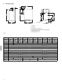
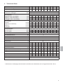
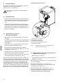
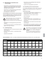
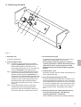
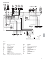
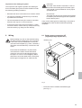
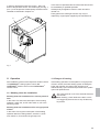
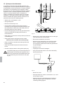
D
GA 110 E
Installationsanleitung
Installation manual
GB
Deutsch
GA 110 E
Gas-Spezial-Gussheizkessel mit elektronischer Zündung
Installationsanleitung
Inhaltsverzeichnis
Symbole und Warnhinweise . . . . . . . . . . . . . . . . . . . . 2
9
1
2
Beschreibung . . . . . . . . . . . . . . . . . . . . . . . . . . . . . . . 3
Vorschriften . . . . . . . . . . . . . . . . . . . . . . . . . . . . . . . . . 3
10
10
3
Garantie . . . . . . . . . . . . . . . . . . . . . . . . . . . . . . . . . . . . 3
4
Lieferumfang . . . . . . . . . . . . . . . . . . . . . . . . . . . . . . . . 3
5
Abmessungen . . . . . . . . . . . . . . . . . . . . . . . . . . . . . . . 4
6
Technische Daten . . . . . . . . . . . . . . . . . . . . . . . . . . . . 5
7
Installation . . . . . . . . . . . . . . . . . . . . . . . . . . . . . . . . . . 6
10.1 Funktionskontrolle . . . . . . . . . . . . . . . . . . . . . . .
10.2 Entriegelung des Sicherheitstemperaturbegrenzers STB . . . . . . . . . . . . . . . . . . . . . . . .
10.3 Entriegelung der Abgasüberwachung . . . . . . . .
11 Bedienung . . . . . . . . . . . . . . . . . . . . . . . . . . . . . . . . .
11.1 Außerbetriebnahme der Anlage . . . . . . . . . . . .
11.2 Frostgefahr . . . . . . . . . . . . . . . . . . . . . . . . . . . .
12 Pflege und Wartung . . . . . . . . . . . . . . . . . . . . . . . . .
12
8
7.1 Aufstellungsort . . . . . . . . . . . . . . . . . . . . . . . . . .
7.2 Heizungsseitige Anschlüsse . . . . . . . . . . . . . . . .
7.3 Gasinstallation . . . . . . . . . . . . . . . . . . . . . . . . . . .
7.4 Abgasanschluß . . . . . . . . . . . . . . . . . . . . . . . . . .
Verdrahtung . . . . . . . . . . . . . . . . . . . . . . . . . . . . . . . . .
9.1 Gerätekontrolle . . . . . . . . . . . . . . . . . . . . . . . . .
9.2 Gaseinstellung nach der Düsendruckmethode .
9.3 Gaseinstellung nach der volumetrischen
Methode . . . . . . . . . . . . . . . . . . . . . . . . . . . . . .
9.4 Überprüfung des Gasfließdruckes . . . . . . . . . . .
9.5 Funktionsprüfung . . . . . . . . . . . . . . . . . . . . . . . .
9.6 Umstellung auf eine andere Gasart
Gaseinstelltabelle . . . . . . . . . . . . . . . . . . . . . . . .
10 Betriebsbereitstellung . . . . . . . . . . . . . . . . . . . . . . . .
8.1 Anschluß Kesselfühler KF
(Zubehör) . . . . . . . . . . . . . . . . . . . . . . . . . . . . . . .
8.2 Anschluß Regelung rapidomatic®
(Zubehör) . . . . . . . . . . . . . . . . . . . . . . . . . . . . . . .
8.3 Anschluß Raumuhrenthermostate
(Zubehör) . . . . . . . . . . . . . . . . . . . . . . . . . . . . . . .
8.4 Anschluß Fernbedienung comfortmatic T /RFFT
(Zubehör) . . . . . . . . . . . . . . . . . . . . . . . . . . . . . . .
6
6
6
6
7
7
8
9
9
Gaseinstellung . . . . . . . . . . . . . . . . . . . . . . . . . . . . . 10
10
11
11
11
12
12
12
13
13
14
14
13 Bedienung Schaltfeld . . . . . . . . . . . . . . . . . . . . . . . . 15
14 Störungsbehebung . . . . . . . . . . . . . . . . . . . . . . . . . . 16
15 Schaltplan . . . . . . . . . . . . . . . . . . . . . . . . . . . . . . . . . 37
Symbole und Warnhinweise
– Warnen Sie alle anderen Hausbewohner und verlassen Sie das Gebäude.
In der Installationsanleitung werden folgende Benennungen bzw. Zeichen für besonders wichtige Hinweise benutzt.
– Benachrichtigen Sie das Gasversorgungsunternehmen oder die Heizungsfachfirma.
Angaben bzw. Ge- und Verbote zur Verhütung
von Personen- oder schweren Sachschäden.
Angaben zu Arbeiten an der elektrischen Anlage.
Verhalten bei Abgasgeruch
– Schalten Sie die Anlage aus. Bringen Sie dazu den
Hauptschalter in Stellung „off“.
– Öffnen Sie Fenster und Türen zum Durchlüften!
Hinweise zum Umweltschutz.
☞
Hinweise zur wirtschaftlichen Verwendung oder
einfacheren Handhabung.
Verhalten bei Gasgeruch
– Vermeiden Sie unbedingt Funkenbildung und offenes
Feuer! Rauchen Sie nicht und vermeiden Sie die Benutzung elektrischer Geräte, wie z.B. Telefon, Klingel,
Lichtschalter usw.
– Schließen Sie den Gas-Haupthahn.
– Öffnen Sie Fenster und Türen zum Durchlüften!
2
– Benachrichtigen Sie die Heizungsfachfirma.
Weitere Warnhinweise
– Lagern oder verwenden Sie niemals explosive oder
leicht entflammbare Stoffe (z.B. Benzin, Farben, Papier etc.) im Aufstellraum.
– Nehmen Sie keine Veränderungen am Gerät, den Armaturen oder baulichen Gegebenheiten vor.
– Aggressive chemische Bestandteile in der
Verbrennungsluft können zu Korrosion des Brenners
und des Abgassystems führen. Eine verkürzte Lebensdauer wäre die Folge. Deshalb sollte der Aufstellraum
frei von Lösungsmitteln, chlorhaltigen Reinigungsmitteln, Farben, Klebstoffen, Sprays, Waschpulver usw.
sein.
1
Beschreibung
Rapido Gas-Spezial-Gussheizkessel werden als Wärmeerzeuger für Warmwasser-Zentralheizungen verwendet.
Sie dienen zum Betrieb von Neuanlagen ebenso wie zur
Modernisierung bestehender Heizungsanlagen in Wohnungen, in Ein- und Mehrfamilienhäusern sowie in gewerblichen Betrieben.
Alle Gaskessel sind mit atmosphärischen Gasbrennern ohne Gebläse ausgerüstet, NOx-reduziert und können auf die verschiedenen Gasarten nach DVGWArbeitsblatt G 260, ”Richtlinien für die Gasbeschaffenheit”,
umgestellt werden. Der Kessel ist werkseitig voreingestellt auf Erdgas H, Wo = 15 kWh/m³.
Der GA 110 E kann für Heizungsanlagen mit bis zu zwei
gemischten Heizkreisen und einem Brauchwasserkreis
eingesetzt werden.
Bei Anlagen mit Fußbodenheizung, bei Anlagen mit
mehreren Heizkreisen oder solchen mit großem
Wasserinhalt ist aufgrund der Anlagenbedingungen
eine Heizkreisregelung über Heizungsmischer vorzusehen. Als Grenzwerte für den Wasserinhalt der Heizungsanlage gelten bei Heizungsauslegung mit:
∆T = 10 K
ca. 75 l bei 10 kW
∆T = 20 K
ca. 150 l bei 10 kW
Der GA 110 E ist mit einem vollautomatischen Gasbrenner mit elektronischer Zündung ausgestattet.
Bei Wärmeanforderung wird über ein elektronisches
Zündsystem der Zündgasbrenner gestartet, erst danach
wird die Stufe für die Hauptflamme freigegeben. Die Absicherung erfolgt über eine Ionisationsüberwachung.
2
Vorschriften
Der Kessel besitzt das CE-Zeichen und ist damit für den
Vertrieb und den Einbau im Bereich des EU-Binnenmarktes zugelassen. Bei Aufstellung und Installation des Kessels sind die länderspezifischen Richtlinien, die regionalen Bauordnungen sowie die gewerblichen,
emissionsschutzrechtlichen und wasserrechtlichen Vorschriften zu beachten. Diese verweisen unter anderem
auf:
– DVGW-TRGI 1986, Technische Regeln für Gasinstallation und die Ergänzung der DVGW-TRGI 1986,
Ausgabe 1996, sowie TRF
– Heizraum-Richtlinien bzw. Bauordnung der Länder
(FeuVo)
– HeizAnlV
– Heizungsanlagen-Verordnung
– HeizBetrV
– Heizungsbetriebs-Verordnung sowie Anforderungen
und Auflagen der Bau- und evtl. Gewerbeaufsichtsämter
– VDE-Vorschriften
– DIN 4751 Teil 1 und Teil 2, Sicherheitstechnische Ausrüstung von Heizungen mit Vorlauftemperaturen bis
110°C
In Österreich ist die ÖVGW Richtlinie G1 ( ÖVGW-TRG )
zu beachten.
3
4
Garantie
Die Garantie für den Gußblock beträgt 24 Monate, für
alle anderen Teile 12 Monate. Die Garantie beginnt mit
der Installation.
Lieferumfang
Zum Lieferumfang gehören diese Installationsanleitung
mit Schaltplänen, die jeweilige Bedienungsanleitung und
die Ersatzteilliste. Alles zusammen befindet sich – in einer Kunststofftasche – auf der rechten Kesselseite. Der
Gaskessel wird kartonverpackt auf Holzpalette geliefert.
3
5
Abmessungen
C1
C2
A1
5
1
B3
C3
4
B1
B
6
2
B6
B2
B5
3
B4
A
C
Vorderansicht
A2
Justierfüße
Rückansicht
Seitenansicht
1
2
3
4
5
6
Vorlauf
Rücklauf
Rücklauf / (GA 110 EU)
Gasanschluß (Anschlüsse Außengewinde)
Steckerleiste Fühler
Steckerleiste 230 V
Abb. 1
Maße mm
GA 110
/9 E
GA 110
/15 E
GA 110
/19 E
GA 110
/23 E
A
A1
445
173,5
445
202
502
230,5
559
259
A2
135
GA 110
/27 E
GA 110
/31 E
GA 110
/35 E
GA 110
/41 E
616
287,5
673
316
730
344,5
787
373
805
B1
B2
810
450
B3
80
B4
B5
110
398
B6
C
C1
543
545
C3
4
844
401,5
80
B
C2Ø
GA 110
/46 E
720
90
110
72
730
130
82
150
180
91
GA 110
/51 E
901
430
6
Technische Daten
Typ
GA 110/
9 E 15 E 19 E 23 E 27 E 31 E 35 E 41 E 46 E 51 E
Nennwärmeleistung
kW
8,6 14,9 19,9 23,6 27,6 32,9 37,6 42,4 47,2 50,8
Nennwärmebelastung
kW
9,5 16,4 21,9 25,1 30,4 36,2 41,4 46,6 51,9 55,9
Gasanschluß Erdgas Gruppe E und LL
mbar
20
Gasanschluß Flüssiggas
mbar
50
Anschlußwerte
Erdgas E, HuB = 10,0 kWh/m³
m³/h 0,95 1,64 2,19 2,59 3,04 3,62 4,14 4,66 5,19 5,59
Erdgas LL, HuB = 8,6 kWh/m³
m³/h 1,10 1,90 2,54 3,01 3,53 3,20 4,81 5,42 6,03 6,50
Flüssiggas, HuB = 12,8 kWh/kg
kg/h 0,74 1,28 1,71 2,02 2,38 2,82 3,23 3,64 4,05 4,37
Brennerdüsen
Erdgas E
mm Ø 2,35 2,25 2,20 2,00 2,15 2,15 2,05 2,00 2,00 1,95
Erdgas E (nur Östereich)
mm Ø 2,50 2,25 2,20 2,00 2,15 2,15 2,20 2,00 2,00 2,05
Erdgas LL
mm Ø 2,90 2,75 2,65 2,45 2,60 2,60 2,50 2,45 2,45 2,35
Flüssiggas
mm Ø 1,50 1,40 1,35 1,25 1,35 1,35 1,25 1,25 1,20 1,20
Kesselwiderstand
bei ∆ T = 10 K
mbar
5,9 15,4 28,2 41,7 56,7 74,9 93,9 125,5 153,1 180,8
bei ∆ T = 20 K
Vorlauftemperatur max. Einstellbar
mbar
°C
1,5 3,85 7,05 10,4 14,2 18,7 23,5 31,4 38,3 45,2
85
zul. Gesamtüberdruck
bar
4
V/Hz
W
230/50
6,2
Vor- und Rücklaufanschluß
R
1
Gasanschluß
R
1/2
Elektroanschluß
elektrische Leistungsaufnahme
Gewicht
kg
75
80
100
115
130
135
145
160
170
182
l
4,2
5,0
5,8
6,6
7,4
8,2
9,0
9,8 10,6
11,4
1/3
2/4
3/5
4/6
4/7
5/8
6/9 7/10 8/11 9/12
g/s
°C
8
98
8,5
102
11,2 14,9
111 114
19
115
22 25,3 39,7 44,6 49,9
119 113 116 109 114
CO2-Gehalt
CO-Gehalt
%
mg/kWh
4,4
6
4,5
10
5,7
7
5,5
7
NOX
mg/kWh
53 61,8 37,5
41 60,5 43,4 49,7 57,6 35,6 30,7
7,0
7,0
Wasserinhalt
Anzahl Brennerrohre/Glieder
Abgasmassenstrom *
Abgastemperatur * bei Nennleistung brutto
Abgasverlust
notwendiger Förderdruck
CE-Produkt-Ident-Nr.
%
Pa
7,1
5,3
6
6,9
5,5
6
6,8
7,3
5,3
5
7,1
5,4
8
7,0
5,1
5
7,0
5,2
5
7,5
3
CE-0085AR0441
* Rechenwert zur Auslegung des Schornstein nach DIN 4705. Kessselserie GA 110 E geprüft nach RAL-UZ 39.
5
7
7.3 Gasinstallation
Installation
Die Installation des Rapido-Gas-Spezialkessels muß von
einem anerkannten Fachmann durchgeführt werden. Dieser übernimmt auch die Verantwortung für eine fach- und
normgerechte Installation und Erstinbetriebnahme. Es sind
zutreffende Maßnahmen zu ergreifen, um den Geräuschpegel bei der Installation zu begrenzen.
Im Rahmen der Typprüfung wurde nachgewiesen,
daß die Installation einer Wassermangelsicherung
nach DIN 4751 Teil 2 nicht erforderlich ist.
7.1 Aufstellungsort
Die Aufstellung soll in einem frostgeschützten Raum in
der Nähe eines Abgasschornsteins erfolgen. Bei Nischeneinbau darauf achten, daß für die spätere Reinigung und
Wartung ausreichend Platz vorhanden ist.
Lösbare Verbindungen und entsprechende Absperrorgane
in der Heizungsanlage sind empfehlenswert.
Der Aufstellungsraum muß gut belüftet, frei von
starkem Staubanfall und aggressiven Dämpfen
(z. B. Treibgas und Lösungsmittel) sein.
Die Gasinstallation darf nur durch einen Fachmann vorgenommen werden. Die Bestimmungen der länderspezifischen Technische Regeln für Gasinstallation sowie
evtl. örtliche Vorschriften des Gasversorgungsunternehmens GVU sind zu beachten.
In der Gaszuleitung sind vor dem Kessel ein Absperrhahn
und eine thermisch auslösende Absperreinrichtung anzuordnen. Die Gaszuleitung ist nach den Angaben der
Technischen Regel für Gasinstallation auszulegen. Der
Gasanschluß ist nach hinten aus dem Kessel geführt.
Die Anschlußdimensionen können der Tabelle Technische Daten (siehe Kapitel 6) entnommen werden.
Alle Kessel sind werkseitig mit Düsen für Erdgas H ausgerüstet. Düsen für Erdgas L sind beigefügt (nicht für
Österreich).
Die Gasbrennerarmaturen dürfen höchstens
mit 50 mbar abgedrückt werden. Arbeiten am
Gasregelblock oder an der elektrischen
Verdrahtung dürfen nur vom Fachmann
ausgeführt werden.
Die Gasverschraubung des Gasregelblockes
darf nur mit einem Drehmoment von max. 60
Nm angezogen werden.
7.2 Heizungsseitige Anschlüsse
Den Heizungsvorlauf und -rücklauf entsprechend den Angaben der Abb. 1 installieren.
Ein Druckausdehnungsgefäß sollte, sofern es nicht zum
Lieferumfang des Kessels gehört, bauseits im Rücklauf
des Kessels eingebaut werden.
[mbar]
Zur Entleerung des Kessels muß der Füll- und
Entleerungshahn im linken Außenglied und das
Entleerungsventil im rechten Außenglied geöffnet
werden. So wird die Anlage vollständig entleert
und vor eventuellen Frostschäden geschützt.
Hinweis zur Schornsteinausführung
Die Eignung des Schornsteins muß nach den gültigen
Normen (DIN 4705, DIN 18 160) errechnet werden.
250
150
100
50
0
0
0,5
1
1,5
2
2,5
3
3,5
4
4,5
5
[m³/h]
Wasserseitiger Durchflußwiderstand [mbar] des
GA 110 E als Funktion der Wassermenge [m³/h]
Bei Anschluß von Speicher-Wassererwärmern mit
Speicherladepumpe darauf achten, daß im Speichervorlauf und im Heizungsvorlauf eine Rückschlagklappe
(Schwerkraftbremse) eingebaut wird.
6
Der Abgasanschluß ist aus Abb.1 ersichtlich. Das
Abgasrohr sollte ca. 50 cm senkrecht nach oben geführt
und zum Schornstein hin steigend verlegt werden.
Bestimmungen hinsichtlich der Abgasführung,
insbesondere auch der Schornsteinquerschnitte, sind zu
beachten. Der Schornstein ist durch den
Schornsteinfeger auf Eignung zu prüfen. Hierbei muß
speziell das Problem eventueller Kondensation beachtet
werden. Grundsätzlich sollte die Stellungnahme des
Bezirksschornsteinfegermeisters eingeholt werden.
300
200
Abb. 2
7.4 Abgasanschluß
Überprüfung der Abgasanlage
Die Überprüfung der Abgasanlage auf einwandfreie
Abgasführung muß unter folgenden Betriebsbedingungen durchgeführt werden.
Der untere Wert soll wegen der einwandfreien
Abgasführung nicht unterschritten werden und
der obere Wert zur Erzielung eines guten
Wirkungsgrades nicht überschritten werden.
– Fenster und Türen im Aufstellungsraum müssen geschlossen sein.
Je niedriger der Schornsteinzug (im zulässigen
Bereich), desto besser ist der feuerungstechnische Wirkungsgrad der Gasfeuerstätte.
– Die vorgeschriebenen Lüftungseinrichtungen dürfen
nicht geschlossen, verstellt oder verengt werden.
– Der empfohlene Schornsteinzug muß mindestens
0,03 mbar und darf maximal 0,1 mbar betragen.
Die Abgasverlustmessung nach BlmSchV ebenfalls unter
den vorgenannten Betriebsbedingungen durchführen.
– Bei einem Schornsteinzug über 0,1 mbar Rücksprache
mit dem Bezirksschornsteinfegermeister zwecks Abhilfemaßnahmen (z.B. Einbau eines Zugbegrenzers) halten.
8
Verdrahtung
8.1 Anschluß Kesselfühler KF
(Lieferumfang Regelung rapidomatic®)
Vor Beginn der Elektroverdrahtung müssen alle
Leitungen spannungsfrei gemacht werden.
Die Anbindung an die Netzspannung muß über
einen festen Anschluß und eine Trennvorrichtung
(z.B. Sicherung, LS-Schalter) erfolgen. Die
Erdung des Kessels muß beim Anschluß an das
elektrische Netz erfolgen.
Beim Netzanschluß muß unbedingt die
Phasengleichheit beachtet werden. Phase und
Nulleiter dürfen nicht vertauscht werden (siehe
Beschriftung der Abdeckkappe oder Schaltplan).
Netz- und Fühleranschlußleitungen sollten in
keinem Fall in einem Rohr oder Kabelbaum
verlegt werden.
Kesseltauchhülse
Abb. 3
– Der Kesselfühler wird in die Kesseltauchhülse gesteckt (siehe Abb. 3).
7
Bauseitige elektrische Verbindung:
GA
11
0E
Die bauseitige elektrische Verbindung ist an den entsprechenden Steckern auf der Rückseite des Kessels vorzunehmen. Betrachtet man den Kessel von vorne so befinden sich auf der linken Seite der Kesselrückwand die
230 V-Stecker und auf der rechten Seite der Kesselrückwand die Fühlerstecker.
Wir empfehlen, zunächst einen der benötigten Stecker
(z.B. Netz) abzuziehen und die einzelnen Kabeladern
gemäß der Steckerbeschriftung anzuschließen. Anschließend wird der Stecker wieder aufgesteckt. Dann folgt die
Verdrahtung des nächsten Bauteils (z.B. Pumpe 1) usw.
8.2.1 Anschluß Regelung rapidomatic® T2S
Die elektrischen Anschlüsse sind an den folgenden Stekkern vorzunehmen:
Spannungsversorgung:
Stecker Netz
– Die Blindblende im Kesselschaltfeld ist zu entfernen.
Dazu muß die Blindblende mit Hilfe eines Schraubendrehers entriegelt werden (siehe Abb. 4).
Heizungsumwälzpumpe:
Stecker Pumpe 1
Speicherladepumpe:
Stecker Ladepumpe
– Das freie Kabelende muß durch eine unter dem
Schaltfeld befindliche freie Öffnung in das Schaltfeld
hinein geführt werden.
Außenfühler:
Stecker AF
Speicherfühler:
Stecker SF
Abb. 4
Entriegelung der Blindblende
– Die Drähte des Kabels sind an der losen, 5-poligen
Reihenklemmleiste (Lüsterklemme) mit der Beschriftung KF im Schaltfeld anzuschließen.
8.2.3 Anschluß Regelung rapidomatic® T 2.3 S
Die elektrischen Anschlüsse sind an den folgenden Stekkern vorzunehmen:
Spannungsversorgung:
Stecker Netz
Heizungsumwälzpumpe
Radiatorenkreis DK1:
Stecker Pumpe 1
Die elektrische Verbindung zwischen Regelung und
Kesselschaltfeld erfolgt mittels der vorverdrahteten Stekker. Durch Kodierung der Stecker besteht beim Aufstekken keine Verwechslungsgefahr der Positionen.
Speicherladepumpe:
Stecker Ladepumpe
Heizungsumwälzpumpe
Mischerkreis MK2:
Stecker Pumpe 2
Anschließend wird die Regelung in die Aussparung im
Kesselschaltfeld eingeschoben und mit den beiden
Befestigungsnocken mittels eines Schraubendrehers befestigt.
Mischermotor MK2:
Stecker Mischer 2
Außenfühler:
Stecker AF
Zum Betrieb drehen Sie den Kesseltemperaturregler
ganz nach rechts bis zum Endanschlag und stellen den
auto/man/TÜV-Schalter auf Stellung auto.
Weitere Informationen zur Verdrahtung siehe Installationsanleitung der jeweiligen Regelung rapidomatic®.
Speicherfühler:
Stecker SF
Vorlauffühler MK2:
Stecker VF-MK 2
8.2 Anschluß Regelung rapidomatic® (Zubehör)
Elektrische Verbindung zwischen Regelung und
Kesselschaltfeld:
8
8.2.4 Anschluß Regelung rapidomatic® TZ 2.3.3 SV
Die elektrischen Anschlüsse sind an den folgenden Stekkern vorzunehmen:
Anlage ohne Brauchwasserbereitung (ohne Regelung rapidomatic® S):
Spannungsversorgung:
Stecker Netz
Bei einer Anlage ohne Brauchwasserbereitung kann der
Raumuhrenthermostat am Stecker MA, motorische Abgasklappe angeschlossen werden.
Heizungsumwälzpumpe
Mischerkreis MK1:
Stecker Pumpe 1
8.4 comfortmatic T / RFFT (Zubehör)
Mischermotor MK1:
Stecker Mischer 1
Die comfortmatic T, bzw. der RFFT ist am RMF-Stecker zu
verdrahten:
Speicherladepumpe:
Stecker Ladepumpe
comfortmatic T / RFFT, Klemme A: Stecker RMF, A Signal
comfortmatic T / RFFT, Klemme B: Stecker RMF, B 0 Volt
Heizungsumwälzpumpe
Mischerkreis MK2:
Stecker Pumpe 2
Mischermotor MK2:
Stecker Mischer 2
Außenfühler:
Steckerf AF
Speicherfühler:
Stecker SF
Vorlauffühler MK 1:
Stecker VF-MK 1
Vorlauffühler MK 2:
Stecker VF-MK 2
Sollen bei Anschluss einer Zweikreisregelung beide Heizkreise mit jeweils einer eigenen Fernbedienung betrieben
werden, müssen diese parallel am Stecker RMF A Signal
und RMF B 0 Volt angeschlossen werden. Die Zuordnung der comfortmatic T zu dem entsprechenden Heizkreis erfolgt durch Datenbus-Adressierung, bzw. mittels
Drehschalter beim RFFT. Beachten Sie bitte die Anleitungen der Regelungen.
8.2.5 Anschluß Regelung rapidomatic® TS
Die elektrischen Anschlüsse sind an den folgenden Stekkern vorzunehmen:
Spannungsversorgung:
Stecker Netz
Heizungsumwälzpumpe:
Stecker Pumpe 1
Speicherladepumpe:
Stecker Ladepumpe
Speicherfühler:
Stecker SF
8.3 Anschluß Raumuhrenthermostate
(Zubehör)
Anlage mit Brauchwasserbereitung (mit Regelung
rapidomatic® TS):
Bei der Kombination eines Raumuhrenthermostaten mit
einer rapidomatic® TS wird der Raumuhrenthermostat
am Stecker AF angeschlossen.
Anlage ohne Brauchwasserbereitung (ohne Regelung rapidomatic® TS):
Bei einer Anlage ohne Brauchwasserbereitung kann der
Raumuhrenthermostat am Stecker MA, motorische Abgasklappe angeschlossen werden.
Anlage mit Brauchwasserbereitung (mit Regelung
rapidomatic® S):
Bei der Kombination eines Raumuhrenthermostaten mit
einer rapidomatic® S muß bei dem Kabelbaum mit den
schwarzen Steckern, der direkt auf der rapidomatic® S
aufgesteckt ist, die Brücke zwischen den Positionen 2
und 7 getrennt werden. Der Raumuhrenthermostat wird
am Stecker AF angeschlossen.
9
9
Gaseinstellung
Gaskombi-Armatur GA 110 E
Die Geräte sind werkseitig auf Nennleistung und einen
Düsendruck von 15,0 mbar eingestellt.
(Erdgas H, Wo = 15,0 kWh/m³)
Bei niedrigerem Wobbe-Index Minderleistung
beachten.
9.1 Gerätekontrolle
A
– Entspricht die Geräteausführung nicht der örtlich vorhandenen Gasart, muß die Umstellung auf die vorhandene Gasart vorgenommen werden (siehe Kapitel
9.6).
– Übereinstimmung des Wobbe-Index Wo der örtlich
vorhandenen Gasart mit dem werkseitig eingestellten
Wobbe-Index Wo vergleichen und gegebenenfalls
Gaseinstellung auf erforderlichen Wärmebedarf nach
DIN 4701 vornehmen.
2
3
9.2 Gaseinstellung nach der
Düsendruckmethode
– Absperrhahn in der Hauptgaszuleitung des Kessels
schließen.
– Schraube im Meßanschlußnippel des Ausgangsdrucks
lösen (siehe Abb. 6, Pos. 3) und U-Rohr-Manometer
anschließen.
– Absperrhahn in der Hauptgaszuleitung des Kessels
öffnen und Kessel in Betrieb nehmen.
– Bei eingebauter witterungsabhängiger Heizkreisregelung den Schalter “auto/man/TÜV” auf “man” stellen (siehe Abb. 10, Pos. 2).
– Düsendruck mit dem Tabellenwert (siehe Gaseinstelltabelle) für Nennwärmeleistung vergleichen.
– Falls erforderlich den Düsendruck an der Gasregulierschraube einregulieren (siehe Abb. 6, Pos. 4).
Um den Düsendruck verstellen zu können, müssen Sie
zunächst die Abdeckschraube entfernen. Erst dann wird
die Gasregulierschraube sichtbar. Drehung im Uhrzeigersinn bewirkt Druckerhöhung. Das Ventil reagiert sehr
sensibel auf die Drehbewegung der Einstellschraube,
deshalb sollte diese nur in kleinen Schritten verstellt werden. Bevor Sie weiterdrehen sollten Sie ca. 5 Sekunden
warten, bis sich der neue Düsendruck eingepegelt hat.
Befestigen Sie zum Schluß wieder die Abdeckschraube.
10
1
1
2
3
4
5
4
5
Reset-Knopf
Meßnippel-Eingangsdruck
Meßnippel-Ausgangsdruck
Abdeckung der Gasregulierschraube
Softlite-Stellschraube
Abb. 6
Gasfeuerungsautomat und Gasmagnetventil
Honeywell CVI-Kombination
9.3 Gaseinstellung nach der volumetrischen
Methode (nur bei Erdgas)
– Zählerkontrolle vornehmen.
– Kontrolle des Durchflußvolumens nach der Gaseinstelltabelle vornehmen.
Bei Abweichungen im Bereich von ± 5% ist ein Nachstellen nicht erforderlich.
Bei Abweichungen zwischen - 5% und - 10%:
Düsendruck und damit auch die Gasdurchflußmenge
nachstellen (siehe Kapitel 9.2).
Bei Abweichungen über + 5% und unter - 10%:
Einstellung überprüfen und falls kein Fehler bei der
Düsendruckeinstellung festzustellen ist, Gas versorgungsunternehmen benachrichtigen
9.4 Überprüfung des Gasfließdruckes
– Überzündung und regelmäßiges Flammenbild des
Hauptbrenners prüfen.
(nur bei Erdgas)
– Kunden in die Gerätebedienung einweisen.
– Absperrhahn in der Hauptgaszuleitung des Kessels
schließen. Dichtschraube im Meßanschlußnippel für
Eingangsdruck lösen (siehe Abb. 6, Pos. 2) und URohr-Manometer anschließen.
– Absperrhahn in der Hauptgaszuleitung des Kessels
öffnen und Kessel in Betrieb nehmen.
– Normalfließdruck 18 bis 25 mbar.
Der Gasfließdruck muß mindestens 18 mbar betragen.
Falls der Gasfließdruck unter 18 mbar liegt, ist die Ursache zu ermitteln und zu beheben. Läßt sich kein Fehler
feststellen, das GVU benachrichtigen.
Kessel außer Betrieb nehmen. Der Kessel darf
nicht mehr in Betrieb genommen werden.
– Nach beendeter Einstellung Kessel außer Betrieb nehmen.
– Absperrhahn in der Hauptgaszuleitung des Kessels
schließen.
– U-Rohr-Manometer abnehmen und Dichtschraube im
Meßanschlußnippel festdrehen.
9.6 Umstellung auf eine andere Gasart
Die Umstellung des Kessels auf eine andere Gasart darf
nur von einem qualifizierten Fachmann vorgenommen
werden.
Umstell-Reihenfolge:
– Durchmesser für Brennerdüse und Zündgasdüse* ermitteln (siehe Kapitel 6, Technische Daten)
– Gasabsperrhahn vor dem Kessel schließen
– Strom ausschalten
– Kesseltür öffnen
– vorhandene Brennerdüsen und Zündgasdüse* ausschrauben und die neuen entsprechend der Gasart
einschrauben
– Aufkleber für die neue Gasart auf dem Gasverteilerrohr anbringen
– Kessel entsprechend der Bedienungsanleitung in Betrieb nehmen und die Belastung entsprechend der
neuen Gasart einstellen (siehe Gaseinstelltabelle)
9.5 Funktionsprüfung
* Bei Umstellung auf Flüssiggas ist die Zündgasdüse ∅ 0,5 mm für Erdgas H und L durch die
Zündgasdüse ∅ 0,3 mm für Flüssiggas zu
ersetzen.
Die in der Gaseinstelltabelle angegebenen
Düsendrücke müssen eingehalten werden.
– Gasabsperrhahn öffnen und Kessel in Betrieb nehmen
(siehe Kapitel 10)
– Gesamte Anlage auf wasser- und gasseitige Dichtigkeit prüfen.
– Abgasführung überprüfen.
Gaseinstelltabelle (1 mbar = 10 mmWS ), Düsendrücke für Nennleistung in mbar bei 15°C, 1013 mbar trocken
Gasart
Erdgas E
GA 110/9 E
Wobbe-Index Wo
12,7 - 15,2 kW/m
Düsendruck in mbar
GA 110/15E GA 110/19 E GA 110/23 E GA 110/27 E GA 110/31 E GA 110/35 E GA 110/41 E GA 110/46 E GA 110/51 E
15
14,2
12,6
13,8
15
14,8
15
15
14,7
15
11,7
14,2
12,6
13,8
15
14,8
11,3
15
14,7
12,3
10,3
9,8
9,5
9,5
10,3
10,1
10,3
10,3
10,1
10,3
3
Erdgas E
nur für Österreich
Wobbe-Index Wo
12,7 - 15,2 kW/m
3
Erdgas LL
Wobbe-Index Wo
10,9 - 12,4 kW/m
3
Flüssiggas
Gasart
Erdgas E
Heizwert HuB
10,0 kW/m
GA 110/9 E
Gasdurchfluß in l/min
GA 110/15E GA 110/19 E GA 110/23 E GA 110/27 E GA 110/31 E GA 110/35 E GA 110/41 E GA 110/46 E GA 110/51 E
17
27
37
43
51
60
69
78
87
93
18
32
42
56
59
70
80
90
101
108
3
Erdgas LL
Heizwert HuB
8,6 kW/m
29
3
11
10 Betriebsbereitstellung
10.1 Funktionskontrolle
Die Installation und Wartung muß von einem anerkannten Fachmann durchgeführt werden. Dieser übernimmt
auch die Verantwortung für eine fach- und normgerechte
Installation und Erstinbetriebnahme.
Nach der Installation des Kessels muß der Installateur
den Betreiber über die Bedienung des Kessels und die
Sicherheitseinrichtungen unterrichten und ihm die Bedienungsanleitung übergeben.
Der Gasfeuerungsautomat benötigt einen Ionisationsstrom von nur 0,9 µA und hat eine Sicherheitszeit von 25
Sekunden. Sobald die Ionisation eine Flamme meldet,
wird das Hauptgasventil geöffnet und der Zündfunke erlischt nach ca. 2-3 Sekunden.
– Heizungssystem bis zum erforderlichen Wasserstand
bzw. -druck auffüllen und entlüften.
Die Anzeige des erforderlichen Wasserdruckes kann
mittels der verstellbaren roten Markierung am Manometer erfolgen.
Bei offenen Anlagen nach DIN 4751 Teil 1 und einer
Gesamthärte des Wassers von mehr als 15° dH ist
eine mehrmalige Zugabe von Mehrkomponentenprodukten oder Komplexbildnern empfehlenswert. Es
sind die entsprechenden Gebrauchsanleitungen zu
beachten.
Zur Funktionsprüfung muß das Gerät einmal mit abgezogenem Ionisationsstecker eingeschaltet werden. Es muß
nach 25 Sekunden Sicherheitszeit auf Störung gehen.
Nach dem Wiederaufstecken des Ionisationssteckers
muß der Kessel ohne Störung funktionieren.
Sicherheiten und Schaltfunktionen
Bei einem Flammenausfall im Betrieb wird die Brennstoffzufuhr sofort abgeschaltet und das Gerät macht
nach einer Wartezeit einen neuen Wiederzündversuch.
Bildet sich keine Flamme, geht das Gerät nach Ablauf
der Sicherheitszeit von 10 Sekunden auf Störung.
– Absperrventile der Gasleitung zum Brenner öffnen.
– Gasleitung entlüften.
– Hauptschalter einschalten.
– Kesseltemperaturregler auf die gewünschte Kesseltemperatur einstellen. In Verbindung mit der Heizungsregelung rapidomatic® Kesseltemperaturregler auf
den maximalen Wert einstellen.
– auto/man/TÜV-Schalter auf auto stellen.
Zuerst wird durch den Gasfeuerungsautomat eine Startflamme (Zündflamme) gezündet. Danach wird die zweite
Stufe für den Hauptbrenner freigegeben. Der Hauptbrenner geht nach ca. 12 sec. in Betrieb und der Gasheizkessel wird entsprechend der eingestellten Temperatur aufgeheizt.
Erfolgt keine automatische Zündung, leuchtet die Störlampe im Kesselschaltfeld auf, der Gasfeuerungsautomat muß entriegelt werden.
Hierzu öffnen Sie zunächst die Kesseltür und drücken
den rot leuchtenden Reset-Knopf am Gasfeuerungs automaten (siehe Abb. 6, Pos. 1). Die Störlampe erlischt
und der Kessel ist betriebsbereit.
– Anlage aufheizen.
– Alle Steuer-, Regel- und Überwachungseinrichtungen
auf ihre Funktion und richtige Einstellung überprüfen.
– Bei Wassermangel in der Anlage Wasser bei abgekühltem Kessel nachfüllen.
– Betreiber mit der Bedienung der Anlage vertraut machen.
12
10.2 Entriegelung des Sicherheitstemperaturbegrenzers STB
Ist die Heizungsanlage durch den Sicherheitstemperaturbegrenzer abgeschaltet worden, muß vor erneuter Inbetriebnahme unbedingt die Ursache hierfür ermittelt werden.
Die Entriegelung des Sicherheitstemperaturbegrenzers
befindet sich am Schaltfeld. Zwecks Entriegeln des STB
Schraubkappe entfernen und den darunter befindlichen
Knopf eindrücken.
10.3 Entriegelung der Abgasüberwachung
Die serienmäßig eingebaute Abgasüberwachung
darf nicht außer Betrieb gesetzt werden. Eingriffe,
die die Funktion der Abgasüberwachung
beeinträchtigen, sind nicht zulässig, da bei einer
defekten bzw. nicht richtig funktionierenden
Abgasüberwachung der Kessel nicht abgeschaltet wird, wenn Abgase in den
Aufstellungsraum ausströmen.
Zur Entriegelung der Abgasüberwachung - nach Abkühlung des Temperaturfühlers - muß der Entriegelungsstift
(siehe Abb. 7, Pos. 1) eingedrückt werden. Danach wird
der Kessel, wie unter Kapitel 10 beschrieben, neu gestartet.
2
Bei wiederholtem Abschalten des Kessels muß der Fehler von einem qualifizierten Fachmann behoben werden.
Anschließend ist eine Funktionsprüfung des Gerätes
durchzuführen.
Beim Austausch von defekten Teilen der Abgasüberwachung dürfen nur Originalteile des Herstellers verwendet werden.
A
1
Abb. 7
11 Bedienung
11.2 Frostgefahr
Siehe Installationsanleitung der jeweiligen witterungsgeführten Heizkreisregelung rapidomatic®, die Speicherregelung rapidomatic® S oder die Fernbedienung
comfortmatic®.
Wenn der Heizbetrieb im Winter für längere Zeit unterbrochen wird, muß die gesamte Heizungsanlage einschließlich Kessel und Speicher wasserseitig vollständig
entleert werden. Öffnen Sie den Entleerungshahn und
lassen ihn bis zum Befüllen der Anlage geöffnet.
11.1 Außerbetriebnahme der Anlage
Kurzzeitiges Abschalten der Anlage:
Bei kurzzeitiger Unterbrechung des Heizbetriebs in der
Übergangszeit den Hauptschalter on/off auf ”off ” stellen.
Längerzeitiges Abschalten der Anlage:
Öffnen Sie auch die Entleerungshähne der
Kessel-Außenglieder.
Kontrollieren Sie beim Entleeren, ob der
Entleerungshahn nicht durch Schmutz verstopft
ist und entfernen gegebenenfalls vorhandenen
Schmutz.
Bei längerzeitiger Unterbrechung des Heizbetriebs nach
der Heizperiode den Hauptschalter on/off auf ”off ” stellen
und den Gasabsperrhahn schließen.
13
12 Pflege und Wartung
Gemäß DIN 4755 und DIN 4756 soll jede Gasfeuerungsanlage aus Gründen der Betriebsbereitschaft, Funktionssicherheit und Wirtschaftlichkeit mindestens einmal im
Jahr durch einen Beauftragten der Installationsfirma oder
einen anderen Fachkundigen überprüft werden. Dabei
sind auch die Verbrennungswerte zu prüfen und ggf.
nachzustellen. Es wird empfohlen, einen Wartungsvertrag abzuschließen.
Der Heizraum soll sauber, trocken und gut belüftet sein.
Entsprechend der Brennstoffbeschaffenheit ist der Kessel in bestimmten Zeitabständen zu reinigen, mindestens
aber vor jeder Heizperiode.
– Hauptschalter on/off ausschalten.
1
7,5
±
0,5
– Gasabsperrhahn schließen.
– Frontblech und Abdeckhaube der Verkleidung entfernen.
– Eventuelle Reinigung der Rauchgaszüge durch Demontage des Schaulochdeckels der Strömungssicherung prüfen. Zur Reinigung der Rauchgaszüge
die Strömungssicherung abnehmen.
– Die Gasrohr-Verschraubung oberhalb der Gasarmatur
und die Schrauben der Brennerplatte lösen und den
Brenner nach vorne herausziehen.
– Brenner reinigen. Bei starker Verschmutzung eine
leichte Seifenlauge verwenden.
– Zündbrenner und Zündbrennerdüse reinigen.
Achtung! Düsenöffnung nicht erweitern.
– Brennraum und Rauchgaszüge mit der beiliegenden
Reinigungsbürste säubern.
– Das unter dem Brenner liegende Strahlungsblech reinigen und wieder einsetzen.
– Korrekte Position der Zündelektrode prüfen.
Für ein sicheres Zünden bzw. einen
störungsfreien Betrieb des Brenners ist die
Zündelektrode von großer Bedeutung. Das
werkseitig vorgegebene Maß ist bei
Wartungsarbeiten zu prüfen (siehe Abb. 8).
Abb. 8
– Brenner wieder einbauen. Gasrohr-Verschraubung
oberhalb der Gasarmatur und die Schrauben der
Brennerplatte befestigen.
– Elektrische Verbindung wieder herstellen.
– Schaulochdeckel der Strömungssicherung montieren,
eventuell entfernte Strömungssicherung aufsetzen und
sorgfältig befestigen. Darauf achten, daß die Dichtung
nicht beschädigt wird.
– Abdeckhaube der Verkleidung montieren.
– Gaswege auf Dichtheit überprüfen.
– Alle Regel- und Sicherheitseinrichtungen einer
Funktionskontrolle unterziehen (siehe Abb. 9).
Abb. 9
– Frontverkleidung anbringen.
– Gasabsperrhahn öffnen, Hauptschalter on/off einschalten und Verbrennungswerte prüfen.
– Zur Reinigung der Außenteile genügt ein feuchtes
Tuch, evtl. mit etwas Seifenlauge. Niemals scheuernde und lösende Reinigungsmittel verwenden.
14
13 Bedienung Schaltfeld
2
1
GA
11
0E
3
4
5
6
Abb. 10
1 Störlampe STL
Leuchtet im Störfall auf.
2 auto/man/TÜV-Schalter
auto: Einstellung, die bei Einsatz einer Heizkreisregelung rapidomatic® gewählt werden muß.
Die Einstellung bewirkt, daß Brenner und
Heizungspumpe (Pumpe 1), etc. nach dem Bedarf der rapidomatic® geschaltet werden.
man: Einstellung, die bei ausschließlichem Einsatz
eines Raumuhrenthermostats (RTU) und bei
defekter Heizkreisregelung rapidomatic® vorzunehmen ist. Die Schalterstellung bewirkt, daß
der Brenner über das RTU geschaltet wird und
die gewünschte Kesselvorlauftemperatur am
Kesseltemperaturregler eingestellt werden
kann. Die Heizungspumpe (Pumpe 1) läuft kontinuierlich.
TÜV: Die Schalterstellung dient zur Prüfung der
Schaltfunktion des Sicherheitstemperaturbegrenzers STB. Die Prüfarbeiten dürfen nur
durch den Fachmann vorgenommen werden.
3 Kesseltemperaturregler
Er regelt die Kesselvorlauftemperatur stufenlos. Einstellbar ist eine Temperatur von 33 - 85°C.
Bei eingebauter witterungsgeführter Heizkreisregelung rapidomatic® muß der Kesseltemperaturregler durch drehen im Uhrzeigersinn bis zum
Endanschlag auf den maximalen Wert eingestellt
werden.
4 Hauptschalter on/off
Mit diesem Schalter wird der Kessel eingeschaltet (on)
oder ausgeschaltet (off).
5 Sicherheitstemperaturbegrenzer STB
Der Sicherheitstemperaturbegrenzer schaltet bei Ausfall aller Regelelemente den Brenner ab. Ein automatisches Wiederanlaufen des Brenners ist nicht möglich.
Vor erneuter Inbetriebnahme muß unbedingt die Ursache für das Abschalten der Anlage durch einen Fachmann ermittelt werden. Entriegelung siehe Kapitel
10.2.
6 Einbaumöglichkeit für witterungsgeführte Heizkreisregelung rapidomatic® oder Speicher regelung rapidomatic® S (Zubehör)
Siehe Installationsanleitung der jeweiligen Regelung.
15
14 Störungsbehebung
STÖRUNG
URSACHE
BEHEBUNG
Keine Spannung vorhanden
Sicherung defekt
Sicherung und Anschlüsse überprüfen.
Die Sicherung 6,3 A befindet sich unterhalb
des Schaltfeldes. Um sie zu wechseln, muß
die Kesselvordertür geöffnet und die
schwarze Abdeckkappe der Sicherungsfassung herausgeschraubt werden (siehe
Abb. 7, Pos. 2).Stellung der Thermostate
überprüfen.
Bei der Erstinbetriebnahme
Störmeldung des
Feuerungsautomaten
Phase und Nulleiter vertauscht
Phase auf Klemme L, Nulleiter auf Klemme N
legen (am Stecker)
Luft in der Gasleitung
Gasleitung entlüften
Fehlender oder zu niedriger
Ionisationsstrom.
Mindest. erforderlicher
Ionisationsstrom 5 µA
Ionisationsstrom messen.
Kabelanschluß im Feuerungsautomat und an
der Elektrode überprüfen.
Gas-Austrittsöffnung der Brennerlanze unter
der Ionisationselektrode auf freien
Querschnitt überprüfen, ggf. reinigen.
Ionisationselektrode verschmutzt
oder defekt
Ionisationselektrode reinigen bzw.
auswechseln.
keine Zündung, Zündtrafo defekt
Zündtrafo auswechseln.
Feuerungsautomat defekt
Feuerungsautomat auswechseln.
Falsche Einstellung der
Zündelektrode
Abstände der Zündelektrode zur Brennerlanze und zum Massestab prüfen.
Zündelektrodendraht abgenutzt
Zündelektrode auswechseln, ggf. Abstand
zum Massestab einstellen
Druckregler vom Gasregelventil
öffnet zeitweise nicht
Druckregler auswechseln. Gasfließdruck
prüfen, weil auch der Gasdruckwächter
ausgelöst worden sein kann.
Feuerungsautomat defekt
Feuerungsautomat auswechseln.
Falsche Einstellung der
Zündelektrode
Abstände der Zündelektrode zur Brennerlanze und zum Massestab prüfen.
Schlechter Kontakt des
Zündkabels
Zündkabelanschluß an Trafo und Elektrode
überprüfen.
Isolierkörper der Zündelektrode
defekt
Zündelektrode auswechseln.
Zündelektroden-Draht abgenutzt
Zündelektrode auswechseln, ggf. Abstand
zum Massestab einstellen.
Sicherheitstemperaturbegrenzer
schaltet ab
Kesselthermostat defekt
Thermostat auswechseln.
Brenner brennt gelb
Brenner und / oder
Wärmetauscher verschmutzt
Wartung Kessel / Brenner durchführen.
Störmeldung des Feuerungsautomaten kurz nach dem
Brennerstart
Störmeldung des Feuerungsautomaten in unregelmäßigen
Abständen
Brenner zündet zu laut
Bei allen vorgenannten und allen anderen Störungen* empfiehlt es sich, einen Fachmann zu Rate zu ziehen und die
notwendigen Arbeiten nur von einem Fachmann ausführen zu lassen.
* Bei Störungen bitte den Ersteller der Heizungsanlage benachrichtigen.
16
15 Schaltplan
A B
A B
Abb. 11
Deutsch
A,B,C,...
a
AF
AMT
AÜW
GFA
GMV
HS
IS
KF
L
LP
L1
M
MA
motorische
Abgasklappe
Kennzeichnung von Kabeln
auf
Außenfühler
Schalter auto/man/TÜV
Abgasüberwachung
Gasfeuerungsautomat
Gasmagnetventil
Hauptschalter
Ionisationselektrode
Kesselfühler
Phase 230V, 50Hz
Ladepumpe
Netzphase 230V, 50Hz
Motor
motorische Abgasklappe oder Raumthermostat (nur
bei Anlagen ohne Speicherregelung rapidomatic® TS)
MiMo
N
PE
P1...P12
RMF
RT
SF
Si
STB
STL
TR
VF-MK
z
ZE
ZT
Mischermotor
Nullleiter
Erdung
Bezeichnung der Regelungsstecker
Raumfühler, comfortmatic, RFFT
Raumthermostat
Speicherfühler
Sicherung 6,3A träge
Sicherheitstemperaturbegrenzer
Störlampe
Temperaturregler
Vorlauffühler Mischerkreis
zu
Zündelektrode
Zündtrafo
17
English
GA 110 E
Special Cast-Iron Gas Heating and Hot Water Boiler with
Electronic Ignition
Installation Manual
Table of Contents
Symbols and Warning indications . . . . . . . . . . . . . . . 18
1
Description . . . . . . . . . . . . . . . . . . . . . . . . . . . . . . . . 19
2
Regulations . . . . . . . . . . . . . . . . . . . . . . . . . . . . . . . . 19
3
Guarantee . . . . . . . . . . . . . . . . . . . . . . . . . . . . . . . . . 19
4
Package contents of delivery . . . . . . . . . . . . . . . . . . 19
5
Dimensions . . . . . . . . . . . . . . . . . . . . . . . . . . . . . . . . 20
6
7
Technical specifications . . . . . . . . . . . . . . . . . . . . . . 21
Installation . . . . . . . . . . . . . . . . . . . . . . . . . . . . . . . . . 22
8
7.1 Boiler room . . . . . . . . . . . . . . . . . . . . . . . . . . . .
7.2 Connections on heater side . . . . . . . . . . . . . . .
7.3 Gas installation . . . . . . . . . . . . . . . . . . . . . . . . .
7.4 Waste gas connection . . . . . . . . . . . . . . . . . . . .
Wiring . . . . . . . . . . . . . . . . . . . . . . . . . . . . . . . . . . . .
8.1 Boiler sensor connection
(accessory) . . . . . . . . . . . . . . . . . . . . . . . . . . . .
8.2 Rapidomatic control connection
(accessory) . . . . . . . . . . . . . . . . . . . . . . . . . . . .
8.3 Room clock thermostat RTU
(accessory) . . . . . . . . . . . . . . . . . . . . . . . . . . . .
8.4 Remote control connection for comfortmatic
(accessory) . . . . . . . . . . . . . . . . . . . . . . . . . . . .
22
22
22
22
23
23
24
25
9
Gas setting . . . . . . . . . . . . . . . . . . . . . . . . . . . . . . . . 26
9.1 Appliance check . . . . . . . . . . . . . . . . . . . . . . . .
9.2 Gas setting according to air vent pressure
method . . . . . . . . . . . . . . . . . . . . . . . . . . . . . . .
9.3 Gas setting according to volumetric method . . .
9.4 Gas flow pressure inspection . . . . . . . . . . . . . .
9.5 Functional check . . . . . . . . . . . . . . . . . . . . . . . .
9.6 Conversion to alternative gas type
Gas settings table . . . . . . . . . . . . . . . . . . . . . . .
10 Initial operation . . . . . . . . . . . . . . . . . . . . . . . . . . . . .
10.1 Function monitoring . . . . . . . . . . . . . . . . . . . . . .
10.2 Releasing the safety temperature limiter STB .
10.3 Unlocking the waste gas monitor . . . . . . . . . . .
11 Operation . . . . . . . . . . . . . . . . . . . . . . . . . . . . . . . . . .
11.1 Shutting down the installation . . . . . . . . . . . . . .
11.2 Danger of freezing . . . . . . . . . . . . . . . . . . . . . . .
12 Upkeep and maintenance . . . . . . . . . . . . . . . . . . . . .
26
26
26
27
27
27
28
28
28
28
29
29
29
30
13 Operating the control panel . . . . . . . . . . . . . . . . . . . . 31
14 Trouble shooting . . . . . . . . . . . . . . . . . . . . . . . . . . . . 32
15 Circuit diagrams . . . . . . . . . . . . . . . . . . . . . . . . . . . . 33
25
Warning indications and symbols
In this installation manual the following descriptions or
symbols are used for particularly important indications.
Instructions and prohibitions for the prevention of
personal injury or serious damage.
Instructions for work on the electrical installation
– Contact your local gas supply company or your dealer.
How to proceed when waste gas is smelt
– Switch off the installation. Set main switch into „off“
position.
– Open windows and doors to allow ventilation.
Tips for environmental protection
☞
Further warning indications
Tips for economical use or simpler operation.
How to proceed when gas is smelt.
– It is absolutely necessary to avoid sparks or open fire!
Do not smoke and avoid the use of electrical
appliances such as telephone, doorbell, light switch,
etc..
– Shut off main gas supply.
– Open windows and doors for ventilation.
– Warn all other occupants and evacuate the building.
18
– Contact your dealer.
– Do not store or use explosive or (highly) inflammable
substances (such as petrol, paints, paper, etc.) in the
boiler room.
– Do not carry out any modifications on the heating unit,
fittings, or the actual construction.
– Aggressive chemical substances in the combustion air
may cause corrosion to the burner or the waste gas
system. This would result in reduced burner life. This
is why the boiler room should be free from solvents,
paints, glues, sprays, washing powder, etc.
1
Description
Rapido Special Cast-Iron Gas Heating and Hot Water
Boilers are used for the purpose of heat production for
domestic hot water supply and central heating systems.
They are used in new systems and in the renovation of
existing heating installations in residential houses, singlefamily houses and multiple dwellings as well as
commercial premises.
All gas boilers are fitted with fanless atmospheric
burners, are NOx-reduced and can be converted to
several types of gas in accordance with the DVGWworksheet G260, "Richtlinien für die Gasbeschaffenheit".
The boiler has been pre-set ex-factory for natural gas
type H, Wo = 15 kWh/m³.
The GA 110 E can be used for heating units with up to
two mixed heating circuits and a consumption-water
circuit.
Underfloor heating installations, multiple heating
circuit installations or those with vast quantities of
water are to be fitted with a heating circuit control
via a heat mixer in accordance with system
requirements. The threshold values for the water
content of the heating installation hold for the
following constructions:
∆T = 10 K
ca. 75 l at 10 kW
∆T = 20 K
ca. 150 l at 10 kW
The GA 110 E is fitted with a fully automatic gas burner
and electrical ignition.
When heat is demanded, the pilot burner is ignited by an
electronic ignition system, and subsequently the main
burner is ignited. Safety is monitored via an ionization
gauge.
2
Regulations
The boiler has the CE-mark and has thus been permitted
for marketing and installation within the EU single
market. National directives, regional building regulations
as well as those pertaining commerce, laws on emission
control and the use of water are to be adhered to when
assembling and installing the boiler unit. These refer
among others to:
– Boiler room directives and building regulations
(FeuVo)
– DVGW-TRGI 1986, Technical regulations for gas
installation and the supplement of the DVGW-TRGI
1986, issued 1996, as well as TRF
– Heating Operation regulations as well as standards
and conditions issued by the building and commercial
supervisory departments
– DIN 4751 Part 1 and Part 2, Safety technical
equipment of heating installations with advance
temperatures up to 110°C
– VDE-regulations
3
4
Guarantee
There is a two-year guarantee on the cast-iron block, and
a one-year guarantee on the other parts. The guarantee
period starts on the date of installation completion.
– HeatInstV
– Heating system regulation
– HeatOpV
In Austria the ÖVGW directive G1 (TRG) is to be
adhered to.
Package contents of delivery
The Package contents of delivery comprises this
installation manual, with circuit diagrams, the respective
operating manual and the spare parts list. All this is
contained in a plastic bag on the right side of the boiler
unit. The gas boiler is delivered packed in cardboard
paper box on a wooden pallet.
19
5
Dimensions
C1
C2
A1
5
6
4
B1
B
1
B3
C3
2
B6
B2
B5
3
B4
A
C
front view
A2
adjusting screw
rear view
side view
1
2
3
4
5
6
Water flow
Water return
Water return / (GA 110 EU)
Gas connection
Sensor plugs
230 V plugs
Fig. 1
GA 110
/9 E
GA 110
/15 E
GA 110
/19 E
GA 110
/23 E
A
A1
445
173,5
445
202
502
230,5
559
259
A2
135
Dimensions
in mm
GA 110
/27 E
616
287,5
805
810
450
B3
80
B4
B5
110
398
B6
C
C1
543
545
C3
20
673
316
GA 110
/35 E
730
344,5
GA 110
/41 E
787
373
GA 110
/46 E
844
401,5
80
B
B1
B2
C2Ø
GA 110
/31 E
720
90
110
72
730
130
82
150
180
91
GA 110
/51 E
901
430
6
Technical specifications
Type
GA 110/
9 E 15 E 19 E 23 E 27 E 31 E 35 E 41 E 46 E 51 E
Nominal heating capacity
kW
8,6 14,9 19,9 23,6 27,6 32,9 37,6 42,4 47,2 50,8
Nominal heating rating
kW
9,5 16,4 21,9 25,1 30,4 36,2 41,4 46,6 51,9 55,9
Gas connection Natural gas type (E) and (LL) mbar
20
Liquified gas
Input power
50
mbar
Natural gas (E), HuB = 10,0 kWh/m³
m³/h 0,95 1,64 2,19 2,59 3,04 3,62 4,14 4,66 5,19 5,59
Natural gas (LL), HuB = 8,6 kWh/m³
m³/h 1,10 1,90 2,54 3,01 3,53 3,20 4,81 5,42 6,03 6,50
Liquified gas, HuB = 12,8 kWh/kg
kg/h 0,74 1,28 1,71 2,02 2,38 2,82 3,23 3,64 4,05 4,37
Burner nozzle
Natural gas group (E)
mm Ø 2,35 2,25 2,20 2,00 2,15 2,15 2,05 2,00 2,00 1,95
Natural gas group (LL)
mm Ø 2,90 2,75 2,65 2,45 2,60 2,60 2,50 2,45 2,45 2,35
Liquified gas
mm Ø 1,50 1,40 1,35 1,25 1,35 1,35 1,25 1,25 1,20 1,20
Boiler resistance
at ∆ T = 10 K
mbar
5,9 15,4 28,2 41,7 56,7 74,9 93,9 125,5 153,1 180,8
at ∆ T = 20 K
Water flow temperature max adjustable
mbar
°C
1,5 3,85 7,05 10,4 14,2 18,7 23,5 31,4 38,3 45,2
85
Permissible total overpressure
Electrical connection
power input
Water flow and water return connection
Gas connection
Weight
bar
4
V/Hz
W
230/50
6,2
R
1
R
kg
75
80
100
115
1/2
130
135
145
160
170
182
l
4,2
5,0
5,8
6,6
7,4
8,2
9,0
9,8 10,6
11,4
1/3
2/4
3/5
4/6
4/7
5/8
6/9 7/10 8/11 9/12
g/s
8
8,5
11,2 14,9
19
22 25,3 39,7 44,6 49,9
Waste gas temperature at nominal gross capacity °C
98
102
111
114
115
119
113
116
109
114
CO2-content
4,4
4,5
5,3
5,5
5,7
5,5
5,3
5,4
5,1
5,2
Water content
Number of burner tubes / elements
Waste gas mass flow *
CO-content
NOX
Waste gas losses
Required supply pressure
CE-Product-ID no.
%
mg/kWh
mg/kWh
%
Pa
6
10
6
53 61,8 37,5
6
7
7
5
8
5
5
41 60,5 43,4 49,7 57,6 35,6 30,7
7,0
7,0
7,1
6,9
6,8
3
7,3
7,1
7,0
7,0
7,5
CE-0085AR0441
* Calculated values for chimney construction in accordance with DIN 4705. Boiler series GA 110 E tested in
compliance with RAL-UZ 39.
21
7
7.3 Gas installation
Installation
The Rapido Special Cast-Iron Gas Heating and Hot Water
Boiler is to be installed only by a qualified specialist who
will be responsible for the technical installation, initial
operation, and correct functioning. During the installation
work measures may have to be taken so as to reduce the
level of noise.
Within the framework of the model tests it was shown
that the installation does not require a water shortage
safety device in compliance with DIN 4751 part 2.
7.1 Boiler room
The boiler is to be installed in a frost-free room close to a
waste gas chimney. In the event of the boiler being
installed in an alcove ensure that ample room is available
for cleaning and maintenance work.
It is advisable to fit the heating installation with detachable
connections and respective shut-off devices.
The boiler room must be well ventilated, free from
dust accumulation and aggressive fumes (e.g.
CFK and solvents).
The gas installation is to be carried out only by a qualified
installation engineer. The stipulations of the country
specific technical regulations for gas installation as well
as the local regulations of the gas supply company GVU
must be adhered to. A stopcock and a thermally activated
shut-off device must be fitted in the gas supply pipe
before the boiler. The gas supply pipe must be fitted in
compliance with the specifications and the technical
regulations for gas installation. The gas connection is
fitted at the rear of the boiler. The connection dimensions
can be found in the table of technical specifications (see
Chapter 6). All boilers have been fitted ex-factory with
nozzles for natural gas type H. Nozzles for natural gas
type L are additionally supplied (not Austria).
The maximum pressure for pneumatic pressure
test of the gas burner valves is 50 mbar. Work on
gas control unit or the electrical wiring is to be
carried out only by a qualified specialist.
The maximum torque to seal the gas valve
screwing is 60 Nm.
7.2 Connections on heater side
7.4 Waste gas connection
Fit the heating water flow and water return in compliance
with the specifications in Fig. 1.
It is necessary to fit an expansion vat in the return circuit,
if this is not part of the package suppliedn.
The waste gas connection can be found in Figure 1. The
waste gas pipe must be fitted ca. 50 cm vertically in an
upward direction in respect to the chimney. Stipulations
relating to waste gas flue, in particular also the chimney
diameters, must be adhered to. The chimney must be
checked for suitability by a chimney sweep. Special
attention must be paid to the possibility of condensation
problems. In principle, the opinion of the district master
chimney sweep should be asked for.
[mbar]
The drain and fill cock in the left hand element
and the drain valve on the right hand element
must be opened if the boiler is to be emptied. In
this way the installation is fully emptied and
protected against any possible frost damages.
Instruction for chimney construction
300
The suitability of the chimney must be calculated in
compliance with the applicable standards (DIN 4705, DIN
18 160).
250
200
150
100
50
0
0
0,5
1
1,5
2
2,5
3
3,5
4
4,5
5
[m³/h]
Fig. 2
Flow resistance [mbar] on flow side of the
GA 110 E as a function of the quantity of water [m³/h]
If any boiler for domestic hot water supply with boiler feed
pump is to be connected, ensure that a swing-type check
valve (gravity brake) is fitted in the boiler inlet and in the
heating water flow.
22
Inspection of the waste gas system
Instruction:
The lower value should not be lower in view of
the problem-free waste gas flue and the upper
value should not be exceeded in view of proper
operational level.
The inspection with regard to problem-free waste gas
flue in the waste gas system must be carried out under
the following operating conditions.
– Windows and doors in the boiler room must be closed.
Environment:
The lower the chimney flue (within the permitted
boundaries) the better the pyrotechnic operation
level of the fire place.
– The required ventilation provisions may not be shut,
re-positioned or narrowed.
– The recommended chimney flue must be 0.03 mbar
minimum and may be 0.1 mbar maximum.
– In the event of the chimney flue exceeding 0.1 mbar
consult the district master chimney sweep concerning
corrective action (e.g. fitting in a flue reducer).
8
Wiring
Before starting any work on the electrical wiring
all cables must be voltage-free. The connection
to the mains must be established over a fixed
connection and a splitter (e.g. fuses, LS-Switch).
The boiler must be earthed by connection to the
mains.
Carry out the waste gas loss measuring in accordance
with BlmSchV under the aforementioned operating
conditions.
8.1 Boiler sensor connection KF
(supplied package rapidomatic®)
distributer pipe
Ensure that the installation is in phase when
connected to the mains. Phase and neutral
conductor must not be interchanged (see the
inscription on cover or circuit diagram). Mains
and sensor connection leads must not be jointly
led through one single tube or cable harness.
Fig. 3
– The boiler sensor is fitted into distributer pipe
(see Fig. 3.).
23
The electrical connection to mains:
GA
11
0E
The electrical connection to the mains should be made
by means of the respective plugs on the rear of the
boiler. Viewed from the front of the boiler, the 230 V plugs
are located on the left hand side of the boiler rear cover,
the sensor plugs as well as a plug for the connection of a
motorised exhaust shutter (lower plug with the indication
MA) are located on the right hand side. It is
recommended first to disconnect one of the required
plugs (e.g. the mains plug) and connect each of the
cables in compliance with the plug description.
Subsequently the plug is reconnected. Then the wiring of
the next part (e.g. pump 1) is made, etc
8.2.1 Connecting the rapidomatic® T2S control device
Fig. 4
Unlatching of the blind stop
– Remove the blind stop from the boiler control panel.
The blind stope is to be unlatched by means of a
screwdriver (see Fig. 4).
– The free cable end must be inserted into the control
panel through a vacant opening under the control
panel.
– The wires of the cable are to be connected in the
control panel to the free 5-pole terminal block (strip of
thermoplastic connectors) with the inscription KF.
8.2 Rapidomatic® control connection
(accessory)
Electrical connection between the controls and
boiler control panel:
The electrical connection between the controls and boiler
control panel is effected by means of the already installed
plug and cable. The codes on the plug will prevent the
positions from being interchanged when plugging in.
Subsequently the control unit is fitted in the slot of the
boiler control panel and attached with both fasteners by
means of a screwdriver.
In order to operate, turn the boiler temperature control
knob fully to the right up to the end stop and switch ”auto/
man/TÜV switch” in the auto-position.
For further information as regards the wiring please refer
to the installation manual of the respective rapidomatic®
control device.
24
The electrical connections must be made by means of
the following plugs:
Power supply:
line voltage plug
Heater pump:
pump 1 plug
Boiler feed pump:
charging pump plug
External sensor:
on AF
Boiler sensor:
on SF
8.2.2 Connecting the rapidomatic® T 2.3 S control
device
The electrical connections must be made by means of
the following plugs:
Power supply:
line voltage plug
Heater pump
Radiator circuit DK1:
pump 1 plug
Boiler feed pump:
charging pump plug
Heater pump for
Mixing circuit MK2:
pump 2 plug
Mixing motor circuit 2:
mixing valve 2 plug
External sensor:
AF plug
Boiler sensor:
SF plug
Flow sensor of mixing circuit MK2:
VF-MK 2 plug
8.2.3 Connecting the rapidomatic® TZ 2.3.3 SV
control
Installation without domestic hot water supply
(without rapidomatic® S control):
The electrical connections must be made by means of
the following plugs:
In an installation without domestic hot water supply the
room thermostat can be connected to plug MA, motorische Abgasklappe.
Power supply:
line voltage plug
Heater pump
Radiator circuit DK1:
pump 1 plug
8.4 Remote control connection for
comfortmatic (accessory)
Mixing motor circuit MK1:
mixing valve 1 plug
The comfortmatic must be wired to the RMF-plug:
Boiler feed pump:
charging pump plug
comfortmatic T / RFFT, clamp A: plug RMF, A Signal
comfortmatic T / RFFT, clamp B: plug RMF, B 0 Volt
Heater pump for
Mixing circuit MK2:
pump 2 plug
Mixing motor circuit 2:
mixing valve 2 plug
External sensor:
AF plug
Boiler sensor:
SF plug
Flow sensor of mixing circuit MK1:
VF-MK 1 plug
Flow sensor of mixing circuit MK2:
VF-MK 2 plug
If a rapidomatic double-circuit control unit is to be
connected and if both heating circuits are to be operated
by means of a separate remote control then they should
be connected in parallel to the RMF A Signal plug and B
0 Volt RMF. The adressing of the comfortmatic T to the
corresponding heat circuits occur via parameters.
The micro-switch at the rear is used for adjusting the relevant heat circuit to the RFFT.
Please pay attention to the manuals of the controllers.
8.2.5 Connecting the rapidomatic® S control
The electrical connections must be made by means of
the following plugs:
Power supply:
line voltage plug
Heater pump:
pump 1 plug
Boiler feed pump:
charging pump plug
Boiler sensor:
AF plug
8.3 Room clock thermostat RTU (accessory)
Installation with domestic hot water supply (with
rapidomatic® TS control):
If the rapidomatic® TS control device is combined with a
room thermostat, the room thermostat is to be connected
to plug AF.
Installation without domestic hot water supply
(without rapidomatic® S control):
In an installation without domestic hot water supply the
room thermostat can be connected to plug MA, motorische Abgasklappe.
Installation with domestic hot water supply (with
rapidomatic® S control):
If the rapidomatic® S control device is combined with a
room thermostat, the bridge that is directly connected to the
rapidomatic® S with black plugs between the positions 2
and 7 must be separated in the cable harness. The room
thermostat is to be connected to plug AF.
25
9
Gas setting
Ex-factory the appliances are preset to nominal capacity
and a nozzle pressure of 15.0.
(Natural gas H, Wo = 15.0 kWh/m³)
Attention should be paid to capacity shortage in
the event of low Wobbe index.
A
9.1 Appliance check
– If the appliance type does not comply with the locally
available type of gas, adjustment to the available type
of gas should be carried out. (see Chapter 9.6).
– Check correspondence of the Wobbe-index Wo of the
locally available type of gas with the ex-factory preset
Wobbe-index Wo and adjust gas setting if necessary
to applicable heat requirement according to DIN 4701.
2
3
1
4
5
9.2 Gas setting according to air vent pressure
method
9.3 Gas setting according to volumetric
method (only natural gas)
– Shut stopcock in main gas supply to boiler unit.
– Carry out counter check.
– Release screw in measure device joint of the output
pressure (see Fig. 6, pos. 3) and connect U-tube
manometer.
– Carry out flow rate check based on the gas settings
table.
– Open stopcock in main gas supply to boiler unit and
ignite boiler.
– Set "auto/man/TÜV"-switch of the weather-sensitive
heating circuit control unit (if present) to "man" (see
Fig. 10, pos. 2).
– Compare nozzle pressure with table value (see gas
setting table) for nominal capacity.
– If necessary adjust the nozzle pressure with the gas
adjusting screw (see Fig. 6, pos. 4).
In order to be able to adjust the nozzle pressure, first
remove the cover screw. Only then will the nozzle
pressure adjusting screw become accessible. Clockwise
revolution will effect pressure increase. The valve
responds extremely sensitively to the revolution of the
adjusting screw. Therefore it should be adjusted only in
minute steps.
Before going to the next step wait for approx. 5 seconds
for the new nozzle pressure to have stabilised. Replace
and secure the cover screw on completion of the
foregoing procedure.
26
If deviations do not exceed ± 5% adjustment will not be
required.
If deviations are between - 5% and - 10%:
Adjust the nozzle pressure and consequently also the
flow rate (see Chapter 9.2)
If deviations are over + 5% and below - 10%:
Check settings and if no errors in the nozzle pressure
settings can be detected, contact your gas supplier.
9.4 Gas flow pressure inspection
– Check regularity of flames of main burner.
(natural gas only)
– Demonstrate to customer how to use the system.
– Shut stopcock in main gas supply to boiler unit. Release sealing screw in measure device joint for input
pressure (see Fig. 6, pos. 2) and connect tube
manometer.
9.6 Conversion to alternative gas type
– Open stopcock in main gas supply to boiler unit and
ignite boiler.
Adjustment procedure:
The adjustment of the boiler unit to an alternative type of
gas may only be carried out by a qualified specialist.
– Normal flow pressure 18 to 25 mbar.
– Determine diameter for main nozzle and ignition
nozzle* (see Chapter 6, technical specifications).
The gas flow pressure must be 18 mbar minimum.
– Shut stopcock to boiler unit.
If the gas flow pressure is below 18 mbar, find cause and
carry out corrective action. If no cause can be found,
contact your gas supply company.
– Switch off power supply
Shutting off the boiler unit. The boiler unit may no
longer be put into operation.
– Open boiler unit door
– Unscrew burner nozzle and ignition nozzle * and
subsequently insert and secure the new nozzles that
comply with the new gas type.
– Shut off boiler unit after completion of the adjustment
work.
– Attach label indicating the new type of gas to the gas
distributor.
– Shut stopcock in main gas supply to boiler unit.
– Start up the boiler unit in compliance with the operating
manual and adjust the capacity in accordance with the
new type of gas (see Gas settings table).
– Remove U-tube manometer and secure sealing screw
in measure device joint.
* The Ø 0,5 mm ignition nozzle for H and L
natural gas must be replaced by the Ø 0,3 mm
ignition nozzle for liquified gas in the event of
conversion to liquified gas.
The nozzle pressure listed in the gas settings
tables must be adhered to.
9.5 Functional inspection
– Open stopcock and ignite the boiler unit
(see Chapter 10).
– Check entire system for water or gas leakages.
– Check waste gas flue.
Gas setting table (1 mbar = 10 mmWS ), nozzle pressure at nominal capacity in mbar for 15°C, 1013 mbar dry
Type of gas
Natural gas E
Wobbe-Index Wo
GA 110/9 E
Nozzle pressure in mbar
GA 110/15E GA 110/19 E GA 110/23 E GA 110/27 E GA 110/31 E GA 110/35 E GA 110/41 E GA 110/46 E GA 110/51 E
15
14,2
12,6
13,8
15
14,8
15
15
14,7
15
10,3
9,8
9,5
9,5
10,3
10,1
10,3
10,3
10,1
10,3
12,7 - 15,2 kW/m3
Natural gas LL
Wobbe-Index Wo
10,9 - 12,4 kW/m3
Liquified gas
Type of gas
Natural gas E
Calrific value HuB
29
GA 110/9 E
Gas flow in ltr/min
GA 110/15E GA 110/19 E GA 110/23 E GA 110/27 E GA 110/31 E GA 110/35 E GA 110/41 E GA 110/46 E GA 110/51 E
17
27
37
43
51
60
69
78
87
93
18
32
42
56
59
70
80
90
101
108
10,0 kW/m3
Natural gas LL
Calrific value HuB
8,6 kW/m3
27
10 Initial operation
10.1 Function check
The installation and maintenance must be carried out by
a qualified specialist. He will also be responsible for the
proper technical installation and initial operation in
compliance with applicable standards.
After the installation of the boiler unit, the installation
engineer must demonstrate to the user the operating
procedures and safety devices, and supply him with the
user manual.
The ignition automat requires a ionization current of only
0.9 µA and has a safety time of 25 seconds. As soon as
the ionization reports a burning flame, the main gas valve
is opened and the ignition sparks after 2-3 seconds.
– Fill heating system up to the required water level or
water pressure and purge of air.
The required water pressure can be indicated by
means of the adjustable red pointer on the
manometer.
In open systems according to DIN 4751 Part 1 and a
total hardness exceeding 15° dH repeated addition of
water treatment products or complexing agents is
recommended. The respective user instructions are to
be adhered to.
When checking proper functioning, switch on the
appliance once with unplugged ionization plug. After 25
seconds safety time it should indicate a malfunction. After
plugging in the ionization plug the boiler unit should
function properly without any malfunction.
Safety provisions and switch functions
In the event of flame failure during operation the fuel
supply will be cut off immediately and the appliance will
try to reignite after 25 seconds waiting. Should there be
no flame, then the appliance will switch to malfunction
after expiration of the 10 seconds safety time.
– Open stopcock valve in the gas supply to the burner.
– Purge gas pipe.
– Switch on main switch.
– Set boiler temperature control unit to desired boiler
temperature. Set the boiler temperature control unit to
maximum value in combination with the rapidomatic®
heating control unit.
– Switch „auto/man/TÜV-switch to „auto“.
First a starting (pilot) flame will be ignited by the ignition
automat. Subsequently, the second stage for the main
burner is released. The main burner starts burning after
approx. 12 seconds and the gas boiler will be heated up
to the pre-set temperature.
If there is no automatic ignition, the fault light in the boiler
control panel will illuminate and the ignition automat must
be released.
For this purpose open boiler cabinet door and press the
red illuminated Reset-button of the ignition automat (see
Fig. 6, pos. 1). The alarm light extinguishes and the
boiler unit is ready for use.
– Heat up the installation.
– Check all control, regulating and monitoring devices
with regard to their proper functioning.
– In the event of water shortage, refill the system when it
has cooled down.
– Demonstrate the operation of the installation to the
user.
28
10.2 Unlocking the safety temperature limiter
STL
If the heating system has been switched off by the safety
temperature limiter, it is essential to find the cause before
the system is put into operation again.
The release of the safety temperature limiter is on the
control panel. In order to release the STL, remove screw
cap and press the button underneath.
10.3 Unlocking the waste gas monitor
It is not permitted to switch off the standard builtin waste gas monitor. Interventions that affect the
proper functioning of the waste gas monitor are
not allowed since in the event of a faulty or
malfunctioning waste gas monitor the boiler unit
will not be switched off when waste gasses fill the
boiler room.
In order to release the waste gas monitor - after cool
down of temperature sensor - the release pin (see Fig. 7,
pos. 1) must be pressed. Subsequently the boiler will be
restarted as described in Chapter 10.
In the event of repeated boiler shut down the fault should
be remedied by a qualified specialist.
Subsequently an appliance function check should be
carried out.
Faulty parts in the waste gas monitor may only be
replaced by original parts supplied by the manufacturer.
2
A
1
Fig. 7
11 Operation
11.2 Danger of freezing
See installation manual of the respective weather-sensitive rapidomatic® heating system control, the
rapidomatic® S boiler control or the comfortmatic®
remote control.
If the heating operation is interrupted for a longer period
of time in winter, the entire heating system including the
boiler and domestic hot water boiler will have to be
drained entirely. Open the drain tap and leave the system
open until replenishment.
11.1 Shutting down the installation
Shutting down the installation for a shorter period of
time:
In the event of a short-term interruption of the heating
operation, switch the „on/off“ main switch to „off“ in the
transitory period.
Also open the drain cock of the external elements
of the boiler.
When draining, check whether the drain cock is
not clogged by dirt and remove any dirt that may
be present.
Shutting down the installation off for a longer period
of time:
In the event of a long-term interruption of the heating
operation after the heating season, switch the „on/off“
main switch to „off“ and shut the gas stopcock.
29
12 Upkeep and maintenance
In compliance with DIN 4755 and DIN 4756 each gasheating system must be inspected at least once a year by
a representative of the manufacturer or another qualified
specialist so as to guarantee proper operation, safety
and economic use. This inspection should also comprise
inspection, and if necessary, adjustment of the calorific
value. It is recommended to open a maintenance
contract. The boiler room must be clean, dry and wellventilated. In accordance with the fuel used, the boiler
must be cleaned with regular intervals, at least once a
year before the start of the heating season.
– Switch main „on/off switch“ to „off“
– Shut gas stopcock
1
7,5
±
0,5
– Remove front and top cover.
– Check whether cleaning of the waste gas flue is
necessary by removing the observation hole lid of the
flow safety device. Remove the flow safety device if
the waste gas flue is to be cleaned.
– Unscrew the gas pipe joint over the gas valve and the
screws of the burner bed and pull out burner in
forward direction.
– Clean burner. In the event of heavy build-up of dirt use
a mild detergent.
– Clean ignition burner and ignition burner nozzle.
Attention! Do not widen the nozzle opening.
– Clean combustion chamber and waste gas flue with
brush provided.
– Clean and reinstall the protective sheet under the
burner.
– Check the proper position of the ignition spark plug.
The ignition spark plug is of utmost importance if
proper ignition and trouble-free operation of the
burner is to be ensured. The standard size must
be checked during the maintenance work (see
Fig. 8).
Fig. 8
– Mount burner. Secure the gas pipe joint over the gas
valve and the burner sheet screws.
– Reconnect the electrical connection
– Mount lid to the observation hole of the flow safety
device, install flow safety device if removed and
secure properly. Please ensure that the gasket does
not get damaged.
– Mount top cover.
– Inspect gas conducts for leakages.
– Carry out functional check on all control and safety
devices (see Fig. 9).
Fig. 9
– Mount front cover.
– Open gas stopcock, switch „on/off switch“ to „on“ and
check calorific values.
– A damp cloth (with a mild detergent) will suffice to
clean the cabinet. Never use abrasive or solvent
containing cleaning agents.
30
13 Operating the control panel
2
1
GA
11
0E
3
4
5
6
Fig. 10
1 Fault lamp STL
Illuminates in case of fault.
2 auto/man/TÜV- switch
auto: Setting that must be chosen when the
rapidomatic® control unit is used. The setting
ensures that the burner and pump (Pump 1),
etc. is switched on and off on demand.
man: Setting to be chosen when only a room
thermostat (RTU) is used and if the
rapidomatic® control is disabled. The switch
position ensures that the burner is switched on
and off via the RTU and that the boiler water
flow temperature can be set with the boiler
temperature control unit. The pump (Pump 1)
pumps continually.
TÜV: The switch position is earmarked for the
inspection of the switch function of the safety
temperature limiter STB. The inspection may
only be carried out by a specialist.
3 Boiler temperature control unit
This unit controls continuous control of the boiler water
flow temperature. Temperature settings from 33 85°C.
With built-in weather-sensitive rapidomatic®
control the boiler temperature control must be
turned clockwise to end stop and set to maximum
value.
4 On/off main switch
With this switch the boiler is switched on and off.
5 Safety temperature limiter STB
The safety temperature limiter switches off the burner
in case the control devices are disabled. Automatic
restart is not possible. It is essential to have a specialist find the cause of the disablement of the system
before a restart can be executed. For release see
Chapter 10.2.
6 Installation of rapidomatic® weather-sensitive
heating system control unit or rapidomatic® S
domestic water supply control unit (accessory)
See installation manual of the respective control unit
31
14 Trouble shooting
Faults
Cause
Remedy
no power supply
Faulty fuse
Check fuses and connections.
The 6.3 A fuse is located under the control
panel. For replacing the fuse open the boiler
front door, unscrew and remove the black
cover to the fuse cabinet (see Fig. 7, pos. 2).
Check thermostat settings.
during commissioning fault report Phase and neutral have been
by ignition automat
wrongly connected
Air in gas pipe
Fault report by ignition automat
Absent or insufficient ionization
shortly after burner was activated current.
Required minimum ionization
current value 5 µA
Connect phase to clamp L, and neutral
conductor to clamp N (at plug).
Vent air from gas pipe.
Measure ionization current.
Check cable connection in ignition automat
and to the electrode. Check whether the gas
outlet of the burner lance under the ionization
electrode is not clogged, and clean if
necessary.
Dirty or faulty ionization electrode Clean or replace ionisation electrode.
Ignition absent, faulty ignition
transformer
Replace ignition transformer.
Faulty ignition automat
Replace ignition automat.
Wrong setting of ignition
electrode
Check distance between ignition electrode
and burner lance and earth rod.
Cable of ignition electrode worn
out
Replace ignition electrode, or adjust distance
to earth rod if necessary.
Pressure regulator of gas
regulating valve doesn`t open
temporarily
Exchange pressure controller. Check gas
flow pressure controller, whereas the gas
pressure controller may also have been
switched off.
Faulty ignition automat
Replace ignition automat.
Wrong setting of ignition
electrode
Check distance between ignition electrode
and burner lance and earth rod.
Faulty contact of ignition cables
Check connection to ignition transformer and
electrode.
Faulty insulator of the ignition
electrode
Replace ignition electrode.
Cable of ignition electrode worn
out
Replace ignition electrode, or, if necessary
adjust distance between earth rod.
Safety temperature limiter
switches off
Faulty boiler thermostat
Replace thermostat.
Burner burns with yellow flames
Dirty burner or heat exchanger
Carry out boiler / burner maintenance.
Fault in ignition automat with
irregular intervals
Noisy burner when activated
When the aforementioned and all other malfunctions* occur we recommend consultation of a specialist and have a
specialist carry out the necessary work.
* In case of malfunctioning please contact the manufacturer of the installation.
32
15 Circuit diagram
A B
English
A,B,C,...
a
AF
AMT
AÜW
GFA
GMV
HS
IS
KF
L
LP
L1
M
MA
motorische
Abgasklappe
Marking of cables
open
External sensor
Auto/man/TÜV switch
Waste gas flue control
Ignition automat
Magnetic valve
Main switch
Ionization electrode
Boiler sensor
Power line 230V, 50Hz
Feed pump
Mains phase 230V, 50Hz
Motor
Motor driven waste gas shutter Room thermostat
(only with system without rapidomatic® boiler control)
MiMo
N
PE
P1...P12
RMF
RT
SF
Si
STB
STL
TR
VF-MK
z
ZE
ZT
A B
AC -motor
Neutral
Mains earth
indication of control plugs
Room sensor, comfortmatic, RFFT
Room thermostat
Boiler sensor
Fuse 6.3A inertial
Safety temperature limiter
Fault lamp
Temperature control
Water flow sensor mixing system
close
Ignition electrode
Ignition transformer
33
GA 110 E / EU
Deutsch
Gas-Spezial-Gussheizkessel
Tragen Sie hier die Notrufnummer Ihres
Gasversorgungsunternnehmens (GVU) ein,
um sie für den Notfall zur Hand zu haben.
GVU Telefon-Nr.
English
Special Cast-Iron Gas Heating and Hot Water Boiler
Write down the alarm number of your gas supply
company to ensure that it is at hand in case of an
emergency.
telephon no.
34
Konformitätserklärung
Declaration of conformity
Verklaring van konformiteit
Déclaration de conformité
Gas-Spezialheizkessel
Gas-specialboilers
GA 110/... E
EU-Richtlinien
EU-Directives
90/396/EWG
92/42/EWG
89/336/EWG
73/23/EWG
-
EN 55014
EN 55104
EN 61000-3-2
EN 60335-1
Wir erklären als Hersteller:
Das genannte Produkt erfüllt die Anforderungen der aufgeführten Richtlinien. Es stimmt mit dem geprüften
Baumuster überein. Die Herstellung unterliegt dem Überwachungsverfahren gemäß ISO 9002/EN 29002.
Der GA 110 E unterschreitet den zugelassenen Abgas-Grenzwert von 80mg NOx/kWh und erfüllt damit die
Anforderungen der 1. BImSchV. Der Gas-Spezialheizkessel GA 110/... E ist ein Niedertemperaturkessel.
As manufacturer we declare that:
The product referred to satisfies the requirements of the listed Directives. It conforms to the tested
construction samples. The production has been governed by the quality-assurance procedure of
ISO 9902/EN 929002. The gas-spezialboiler GA 110/... E is a low-temperature boiler.
Viersen, 29.12.97
Geschäftsführung
Managing director
De bedrijfsleider
Le directeur gérant
35
Technische Änderungen, auch ohne vorherige Ankündigung, vorbehalten.
Technical changes may be effected without prior notice.
Die Abbildungen zeigen eventuell Ausstattungsvarianten, die nicht in allen Ländern geliefert werden, bzw. in allen Ländern zugelassen sind.
The pictures may show equipment which might not be delivered or admitted on all
countries.
Bestimmte Abbildungen erfolgen mit Zubehören, die nicht im Grundpreis enthalten
sind.
Some pictures show accessories which are not included in the basic priece of the
equipment.
RAPIDO WÄRMETECHNIK GMBH
Rahserfeld 12, D-41748 Viersen
Postfach 10 09 54, D-41709 Viersen
Telefon: ++ 49 (0) 21 62 / 37 09-0
Fax Zentrale: ++ 49 (0) 21 62 /37 09 67
Fax Kundendienst: ++ 49 (0) 21 62 / 37 09 53
Kundendienst-Hotline: 0180 - 53 53 581*
Internet: http://www.rapido.de/
e-Mail: [email protected]
* 0,12
01-04 Rü
36
Art.-Nr. 008619
pro Minute