1
RUN RUN400HS RUN1200HS Sliding Gate Opener EN-Instructions and warnings for installation and use IT-Istruzioni ed avvertenze per l’installazione e l’uso FR-Instructions et avertissements pour l’installation et l’utilisation ES-Instrucciones y advertencias para la instalación y el uso DE-Installierungs-und Gebrauchsanleitungen und Hinweise PL-Instrukcje i ostrzeżenia do instalacji i użytkowania NL-Aanwijzingen en aanbevelingen voor installatie en gebruik 0682 108mm 387mm 1 400mm 2 1 3 5 E 253mm 3 8 11 10 6 D C 2 F 7 C 4 4 3 12 9 F B A 5 240 0÷10 Max. 40mm 0÷50 400 240 0÷10 6 0÷50 400 2 7 9 10 11 12 13 1÷2mm 8 3÷8 mm 14 1 2 3 4 3 15 16 17 LUCYB TX S.C.A 24V 4W MOFB MOSE RX OPEN CLOSE S.C.A CLOSE OPEN P.P. STOP BLUEBUS Stop Set Open Close L1 L2 L3 L4 L5 L6 L7 L8 FLASH NC NO 4 C C NO NC 18 NC NO C C NO NC LUCYB LUCYB TX MOFB MOSE RX S.C.A STOP OPEN CLOSE S.C.A 24V 4W FLASH S.C.A BLUEBUS L1 L2 L3 L4 L5 L6 L7 L8 P.P. CLOSE CLOSE OPEN OPEN P.P. STOP BLUEBUS STOP BLUEBUS 2 Stop Set 1 Open 2 Close S.C.A 1 BLUEBUS Stop Set Open Close FLASH 24V 4W L1 L2 L3 L4 L5 L6 L7 L8 PP 20 19 F1 F2 F3 21 2 1 5 22 3 1 2 4 6 5 23 1 1 2 2 6 1 EN ENGLISH WARNINGS AND GENERAL PRECAUTIONS 1.1 - Safety warnings Contents IMAGES . . . . . . . . . . . . . . . . . . . . . . . . . . . . . . . . . . . . . . . . . . . . . . . . . 2 - 6 Chapter 1 - WARNINGS AND GENERAL PRECAUTIONS 1.1 - Safety warnings. . . . . . . . . . . . . . . . . . . . . . . . . . . . . . . . . . . . . . . . . . . 1 1.2 - Warnings about installation. . . . . . . . . . . . . . . . . . . . . . . . . . . . . . . . . . . 1 1.3 - Warnings about use. . . . . . . . . . . . . . . . . . . . . . . . . . . . . . . . . . . . . . . . 2 Chapter 2 - PRODUCT DESCRIPTION AND INTENDED USE. . . . . . . . . . . . . . . . . . . . . . . . . . . . . . . . . . . . . . . . . . . . . . 2 Chapter 3 - INSTALLATION 3.1 - Tests prior to installation. . . . . . . . . . . . . . . . . . . . . . . . . . . . . . . . . . . . . 3.2 - Operating limits . . . . . . . . . . . . . . . . . . . . . . . . . . . . . . . . . . . . . . . . . . . 3.2.1 - Product durability. . . . . . . . . . . . . . . . . . . . . . . . . . . . . . . . . . . . . . . 3.3 - Works in preparation for installation . . . . . . . . . . . . . . . . . . . . . . . . . . . . 3.4 - Installation of the gearmotor. . . . . . . . . . . . . . . . . . . . . . . . . . . . . . . . . . 3.5 - Installing brackets with inductive proximity switches. . . . . . . . . . . . . . . . 3.6 - Manually releasing and locking the gearmotor . . . . . . . . . . . . . . . . . . . . 2 2 3 3 4 4 4 Chapter 4 - ELECTRICAL CONNECTIONS . . . . . . . . . . . . . . . . . . . . . . . . 4 4.1 - Description of the electrical connections. . . . . . . . . . . . . . . . . . . . . . . . . 4 Chapter 5 - FINAL CHECKS AND START-UP 5.1 - Selecting the direction . . . . . . . . . . . . . . . . . . . . . . . . . . . . . . . . . . . . . . 5.2 - Connecting to the power supply. . . . . . . . . . . . . . . . . . . . . . . . . . . . . . . 5.3 - Recognition of the devices. . . . . . . . . . . . . . . . . . . . . . . . . . . . . . . . . . . 5.4 - Recognition of the length of the gate . . . . . . . . . . . . . . . . . . . . . . . . . . . 5.5 - Checking gate movement . . . . . . . . . . . . . . . . . . . . . . . . . . . . . . . . . . . 5.6 - Connecting other devices. . . . . . . . . . . . . . . . . . . . . . . . . . . . . . . . . . . . 5 5 5 5 5 6 Chapter 6 - TESTING AND COMMISSIONING 6.1 - Testing. . . . . . . . . . . . . . . . . . . . . . . . . . . . . . . . . . . . . . . . . . . . . . . . . . 6 6.2 - Commissioning . . . . . . . . . . . . . . . . . . . . . . . . . . . . . . . . . . . . . . . . . . . 6 MAINTENANCE. . . . . . . . . . . . . . . . . . . . . . . . . . . . . . . . . . . . . . . . . . . . . . 6 SCRAPPING. . . . . . . . . . . . . . . . . . . . . . . . . . . . . . . . . . . . . . . . . . . . . . . . . 6 Chapter 7 - PROGRAMMING 7.1 - Preset functions. . . . . . . . . . . . . . . . . . . . . . . . . . . . . . . . . . . . . . . . . . . 7.2 - Programming keys. . . . . . . . . . . . . . . . . . . . . . . . . . . . . . . . . . . . . . . . . 7.3 - Programming. . . . . . . . . . . . . . . . . . . . . . . . . . . . . . . . . . . . . . . . . . . . . 7.4 - Level 1 programming (ON-OFF functions). . . . . . . . . . . . . . . . . . . . . . . . 7.5 - Level 2 programming (adjustable parameters) . . . . . . . . . . . . . . . . . . . . 7 7 7 7 8 Chapter 8 - FURTHER DETAILS 8.1 - Adding or removing devices. . . . . . . . . . . . . . . . . . . . . . . . . . . . . . . . . . 9 8.1.1 - BlueBus. . . . . . . . . . . . . . . . . . . . . . . . . . . . . . . . . . . . . . . . . . . . . . 9 8.1.2 - STOP input . . . . . . . . . . . . . . . . . . . . . . . . . . . . . . . . . . . . . . . . . . . 9 8.1.3 - Photocells . . . . . . . . . . . . . . . . . . . . . . . . . . . . . . . . . . . . . . . . . . . . 9 8.1.4 - FT210B Photo-sensor . . . . . . . . . . . . . . . . . . . . . . . . . . . . . . . . . . 10 8.1.5 - RUN “Slave” mode. . . . . . . . . . . . . . . . . . . . . . . . . . . . . . . . . . . . . 10 8.1.6 - Recognition of other devices . . . . . . . . . . . . . . . . . . . . . . . . . . . . . 10 8.1.7 - Radio receiver . . . . . . . . . . . . . . . . . . . . . . . . . . . . . . . . . . . . . . . . 10 8.1.8 - Connecting the Oview programmer . . . . . . . . . . . . . . . . . . . . . . . . 10 8.1.9 - Connecting and installing the backup battery. . . . . . . . . . . . . . . . . 11 8.2 - Special functions. . . . . . . . . . . . . . . . . . . . . . . . . . . . . . . . . . . . . . . . . 11 8.2.1 - The “Always open” function. . . . . . . . . . . . . . . . . . . . . . . . . . . . . . 11 8.2.2 - The “Move anyway” function . . . . . . . . . . . . . . . . . . . . . . . . . . . . . 11 8.2.3 - Maintenance notification. . . . . . . . . . . . . . . . . . . . . . . . . . . . . . . . 11 8.2.4 - Control of the number of manoeuvres performed. . . . . . . . . . . . . . 11 8.2.5 - Manoeuvre counter reset . . . . . . . . . . . . . . . . . . . . . . . . . . . . . . . 11 Chapter 9 - TROUBLESHOOTING... (resolving common problems). . . 9.1 - Diagnostics . . . . . . . . . . . . . . . . . . . . . . . . . . . . . . . . . . . . . . . . . . . . . 9.2 -Troubleshooting. . . . . . . . . . . . . . . . . . . . . . . . . . . . . . . . . . . . . . . . . . . 9.3 - Malfunctions log. . . . . . . . . . . . . . . . . . . . . . . . . . . . . . . . . . . . . . . . . . 9.4 - Flasher signals. . . . . . . . . . . . . . . . . . . . . . . . . . . . . . . . . . . . . . . . . . . 9.5 - Control unit signals. . . . . . . . . . . . . . . . . . . . . . . . . . . . . . . . . . . . . . . . 12 12 12 12 12 13 TECHNICAL CHARACTERISTICS . . . . . . . . . . . . . . . . . . . . . . . . . . . . . . 15 User manual (removable enclosure) . . . . . . . . . . . . . . . . . . . . . . . . . . . . . . . I Declaration of Conformity . . . . . . . . . . . . . . . . . . . . . . . . . . . . . . . . . . . . IX • WARNING! – This manual contains important instructions and warnings regarding safety. Incorrect installation could lead to serious injury. Before starting, please read all sections of the manual carefully. If in any doubt, suspend installation and call the Nice Support Service for clarification. • WARNING! - Important: please retain this manual for future maintenance work and product disposal. Particular warnings concerning the suitable use of this product in relation to the 98/37CE “Machine Directive” (2006/42/CE): • This product comes onto the market as a “machine component” and is therefore manufactured to be integrated to a machine or assembled with other machines in order to create “a machine”, under the directive 2006/42/CE, only in combination with other components and in the manner described in the present instructions manual. As specified in the directive 2006/42/CE the use of this product is not admitted until the manufacturer of the machine on which this product is mounted has identified and declared it as conforming to the directive 2006/95/CE. Particular warnings concerning the suitable use of this product in relation to the 73/23/EEC “Low Voltage” Directive and 2006/95/CE: • This product responds to the provisions foreseen by the “Low Voltage” Directive if used for the use and in the configurations foreseen in this instructions manual and in combination with the articles present in the Nice S.p.a. product catalogue. If the product is used in unforeseen configurations or with other unforeseen products, the requirements may not be guaranteed; the use of the product is prohibited in these situations until compliance with the specified requirements of the directive have been verified by the installers. Particular warnings concerning the suitable use of this product in relation to the 2004/108/CE “Electromagnetic Compatibility” Directive: • This product has been subjected to electromagnetic compatibility tests in the most critical situations of use and in the configurations foreseen in this instructions manual and in combination with the articles present in the Nice S.p.a. product catalogue. If the product is used in unforeseen configurations or with other unforeseen products, the electromagnetic compatibility may not be guaranteed; the use of the product is prohibited in these situations until compliance with the specified requirements of the directive have been verified by the installers. 1.2 - Installation warnings • Before commencing the installation, check that this product is suitable for controlling your gate (see Chapter 3 and the “Product technical specifications”). If it is not suitable, DO NOT continue with the installation. • All installation and maintenance work must be carried out with the automation system disconnected from the electricity supply. If the power disconnection device cannot be seen from where the automation system is positioned, then before starting work a notice must be attached to the disconnection device bearing the words “CAUTION! MAINTENANCE IN PROGRESS”. • Handle the product with care during installation, taking care to avoid crushing, denting or dropping it, or contact with liquids of any kind. Keep the product away from sources of heat and naked flames. Failure to observe the above can damage the product, and increase the risk of danger or malfunction. Should this occur, suspend installation work immediately and contact the Nice Support Service. • Do not modify any part of the product. Operations other than as specified can only cause malfunctions. The manufacturer declines all liability for damage caused by makeshift modifications to the product. • If the gate being automated has a pedestrian gate, then the system must include a control device that will inhibit the operation of the motor when the pedestrian gate is open. • Provide a disconnection device (not supplied) in the plant’s power supply grid, with a contact opening distance that permits complete disconnection under the conditions dictated by overvoltage category III. • WARNING! - Turning on the power supply to the motor before you have completed installation is strictly prohibited. • The key selector must be positioned within view of the automation mechanism, far away from its moving parts, at a minimum height of 1.5 m from the ground and in a location which is not accessible to the public. If it is used in “manned” mode, make sure there are no people in the vicinity of the automation mechanism. • Check that there are no points where people could become trapped or crushed against fixed parts when the gate is fully open or fully closed; if there are, provide protection for these parts. • The product may not be considered a complete anti-intrusion protection system. If you wish to have effective protection, combine the automation mechanism with other security devices. • Check whether other devices are necessary to complete the automation mechanism on the basis of the specific circumstances of use and the hazards present; for example, the risk of impact, crushing, cutting, dragging, etc. and all other dangers must be taken into consideration. • If an automatic switch or a fuse is tripped, identify and eliminate the reason 1 EN before resetting it. • The automation mechanism cannot be used before it has been commissioned as specified in the chapter on “Testing and commissioning”. • Inspect the automation mechanism frequently to check for unbalancing, signs of wear or damage to electrical cables and mechanical parts. Do not use the automation mechanism if adjustment or repair is required. • If it is not used for a long time, remove the optional battery and keep it in a dry place to make sure it does not leak harmful substances. • The packing materials of the product must be disposed of in compliance with local regulations. 1.3 - Warnings about use • The product is not intended for use by persons, including children, with limited physical, sensory or mental capacities, or who lack experience or knowledge, unless supervised or trained in the use of the product by a person responsible for their safety. • Any children near the automation system must be kept under supervision to ensure that they do not play with it. • Do not allow children to play with the fixed control devices. Keep remote control devices out of their reach as well. • Clean the surfaces of the product with a soft, slightly damp cloth. Use only water; do not use cleaning products or solvents. 2 PRODUCT DESCRIPTION AND INTENDED USE This product is intended to be used to automate sliding gates used in residential premises. CAUTION! – All uses other than the intended use described and use in environmental conditions other than those described in this manual should be considered improper and forbidden! RUN is a line of one-way electromechanical gearmotors with electronic controller and SM type connector for the wireless receiver (optional). Electrical connections with external devices are simplified thanks to use of the “BlueBus”, a technique permitting connection of multiple devices with only 2 wires. The list of devices compatible with RUN over the BlueBus network is given in Chapter 7.3.1 “BlueBus”; an up-to-date list, with compatibility specifications, is also available on www.niceforyou.com. RUN has a remote programmer connector to facilitate installation, maintenance and troubleshooting; see Chapter 7.8.1 “Remote programmer”. If mains powered, Run can be fitted with a backup battery to provide power during power failures so that it can be operated for several hours (see par. 7.8.2). In the event of power failure, it is still possible to operate the gate by releasing the gearmotor with its release handle (see par. 3.6). The automation mechanism permits installation of various accessories to add functions and improve security. The RUN product line includes the following products (table 1 - see fig.1). TABLE 1 comparison of basic characteristics of RUN gearmotors Gearmotor type RUN400HS RUN1200HS Type of limit switch electromechanical electromechanical 14 mt 14 mt Max. gate weight 300 kg 1200 kg Maximum startup torque (corresponding to force) 14.7Nm (409N) 28.4Nm (790N) 24V; 5500RPM 24V; 3100RPM Max. gate length Motor Note: 1kg = 9.81N, so that, for instance: 1390N = 142 kg 2 3 INSTALLATION 3.1 - Tests prior to installation Caution! - The installation of RUN must be carried out by qualified personnel in compliance with current legislation, standards and regulations, and the directions provided in this manual. Before proceeding with the installation of RUN you must: • Check that all the materials are in excellent condition, suitable for use and that they conform to the standards currently in force. • Make sure that the structure of the gate is suitable for automation. • Make sure that the weight and dimensions of the gate fall within the specified operating limits provided in chapter 3.2 “Operating limits”. • Check that the force required to start the movement of the gate is less than half the “maximum torque”, and that the force required to keep the gate in movement is less than half the “nominal torque”. Compare the resulting values with those specified in the “Technical Characteristics”. The manufacturer recommends a 50% margin on the force, as unfavourable climatic conditions may cause an increase in the friction. • Make sure that there are no points of greater friction in the opening or closing phases of the gates. • Check that there is no risk of derailment or that the gates may come off their guides. • Make sure that the mechanical stops are sturdy enough and that there is no risk of deformation even if the gate hits the mechanical stop violently. • Make sure that the gate section is balanced, i.e. it must not move if left still in any position. • Make sure that the area where the gearmotor is fixed is not subject to flooding; iff necessary, mount the gearmotor raised from the ground. • Make sure that the installation area enables the release of the gearmotor and that it is safe and easy to release it manually. • Make sure that the mounting positions of the various devices are protected from impacts and that the mounting surfaces are sufficiently sturdy. • Components must never be immersed in water or other liquids. • Keep RUN away from heat sources and open flames; in acid, saline or potentially explosive atmosphere; this could damage RUN and cause malfunctions or dangerous situations. • If there is an access door in the gate, or within the range of movement of the gate, make sure that it does not obstruct normal travel and, if necessary, provide an appropriate interlock system. • Connect the control unit to an electricity supply with a safety earth system. • Connect the gate to the protective earth in accordance with current legislation. • Provide a device on the electricity supply line that ensures complete disconnection of the automation mechanism from the grid. The disconnection device must have contacts with an opening distance large enough to permit complete disconnection under the conditions sanctioned by overvoltage category III, in accordance with installation regulations. The device ensures quick, safe disconnection from the power supply if needed, and must therefore be positioned in view of the automation mechanism. If, on the other hand, it is located in a position which is not visible, there must be a system for preventing accidental or unauthorized reconnection with the power grid to prevent this risk. The disconnection device is not supplied with the product. 3.2 - Operating limits The “Technical Characteristics” chapter provides all the data needed to determine whether the products of the RUN line are suitable for the intended application. The structural characteristics of RUN make it suitable for use on sliding gates in conformity with the limits indicated in tables 2 and 3. The effective suitability of RUN to automate a particular sliding gate depends on the friction as well as other correlated factors, such as ice, that could interfere with the movement of the gate. For an effective control it is absolutely vital to measure the force necessary to move the gate throughout its entire run and ensure that this is less than half of the “nominal torque” indicated in chapter 8 “Technical characteristics” (a 50% margin on the force is recommended, as unfavourable climatic conditions may cause an increase in the friction); furthermore, it is necessary to take into consideration the data indicated in tables 1 and 2 to establish the number of cycles/hour, consecutive cycles and maximum speed allowed. RUN400HS Leave width (m) RUN1200HS Max. no. of cycles/ hour Max. no. of consecutive cycles Max. no. of cycles/ hour Max. no. of consecutive cycles Up to 4 67 33 36 4÷6 45 26 26 6÷8 37 21 8 ÷ 10 29 10 ÷ 12 12 ÷ 14 EN TABLE 2 - Limits in relation to the length of the gate Other fatigue factors (to be considered if the probability of occurrence is greater than 10%) 10% 10% 21 Surrounding temperature greater than 40°C or lower than 0°C or humidity greater than 80% 15 Presence of dust and sand 15% 15% 23 12 Presence of salinity 20% 20% 18 17 10 Operation interrupted by photocell 10% 10% 25 15 14 8 Operation interrupted by Stop 20% 20% 22 13 13 7 Active peak force 10% 10% Total severity index %: TABLE 3 - Limits in relation to the weight of the gate RUN400HS RUN1200HS % cycles % cycles 50 ÷ 100 100% 100% 100 ÷ 200 50 80 200 ÷ 300 30 75 300 ÷ 550 --- 60 550 ÷ 800 --- 50 800 ÷ 1000 --- 40 1000 ÷ 1200 --- 30 The lifetime values specified in the graph are only obtainable if the maintenance schedule is strictly observed (see chapter “Maintenance schedule”). The estimation of durability is made on the basis of design calculations and the results of tests performed on prototypes. As it is only an estimation, it does not represent any form of guarantee on the effective life span of the product. Sample durability calculation: automation of a gate with a door 10 m long with a weight of 150 Kg, installed near the sea: Table 4 shows the “severity index” for this type of installation: 15% (length of gate), 30% (weight of gate) and 10% (ambient temperature > 40°C or < 0°C or humidity > 80%”). These indicators must be added together to obtain the overall severity index, which is in this case 55%. With the value identified (55%), look at the horizontal axis of Graph 1 (“severity index”), and identify the value corresponding to the number of “manoeuvre cycles” our product will be able to perform in its life span, about 180,000 cycles. TABLE 4 - Estimated durability in relation to the cycle severity index Run 1200HS Gate length m Up to 6 5% 5% 6÷9 10% 10% 9 ÷ 12 15% 15% 12 ÷ 14 20% 20% 400.000 350.000 300.000 250.000 200.000 150.000 100.000 50.000 % 0% 10 % 90 % 80 70 % 60 % 50 % 40 % 30 % 20 % 0 10 Durability is the average economic life span of the product. The value of the life span is strongly influenced by the intensity of the manoeuvres, i.e. the sum of all factors that contribute to product wear, see Table 4. To estimate the life span of your automated device, proceed as follows: 01. Add the values of the items in Table 4 regarding the system conditions; 02.In Graph 1 from the value obtained above, trace a vertical line until it intersects the curve; from this point trace a horizontal line until it intersects the line of the “manoeuvre cycles”. The obtained value is the estimated life span of your product. 400HS 500.000 450.000 3.2.1 - Product durability Severity index % GRAPH 1 Durability in cycles Gate weight (kg) Severity index % 3.3 - Works in preparation for installation fig. 2 provides an example of an automation system, produced using Nice components: 1 Key switch 2 FT210B receiver 3Photocells 4 FT210B transmitter 5 Main mobile edge 6 Open stop bracket 7Rack 8 Flasher with integral antenna 9RUN 10Closed stop bracket 11Secondary mobile edge (optional) 12Transmitter These parts are positioned according to a typical standard layout. With reference to fig. 2, locate the approximate position for installation of each component envisaged in the system. Important – Before installation, prepare the electric cables required for the system, with reference to fig. 2 and to “Table 5 - Technical specifications of electric cables”. Caution - When laying the ducting for routing the electrical cables, also take into account that due to possible deposits of water in the routing ducts, the connection pipelines might create condensate in the control unit, with consequent damage to the electronic circuits. Gate weight (kg) 50 ÷ 100 10% 5% 100 ÷ 200 30% 10% 200 ÷ 300 60% 20% 300 ÷ 550 - 30% 550 ÷ 800 - 40% 800 ÷ 100 - 50% 100 ÷ 1200 - 60% 3 EN TABLE 5 - Technical specifications of electric cables (fig. 2) Connection Cable type Maximum admissible length A: POWER cable 1 cable 3 x 1.5 mm 30 m (note 1) B: Cable for FLASHER with antenna 1 cable 2 x 0.5 mm2 1 RG58 type shielded cable 20 m 20 m (recommended less than 5 m) C: PHOTOCELL cable 1 cable 2 x 0.5 mm2 30 m (note 2) 2 D: KEY SWITCH cable 2 cables 2 x 0.5 mm (note 3) 50 m E: Cable for CONNECTION between 2 mobile edges 1 cable 3 x 0.5 mm2 (note 4) 20 m F: Cable for mobile edge CONNECTION 2 cables 2 x 0.5 mm (note 5) 30m 2 2 Note 1 – A power supply cable longer than 30 m may be used provided it has a larger gauge, e.g. 3x2.5mm2, and that a safety earthing system is provided near the automation unit. Note 2 – If the “BlueBus” cable is longer than 30 m, up to 50 m, a larger gauge (2x1mm2) cable is needed. Note 3 – These two cables may be replaced by a single 4 x 0.5 mm2 cable. Note 4 – These cables may be replaced by a single 5 x 1.5 mm2 cable. Note 5 – special devices which enable connection even when the gate is moving must be used to connect movable edges to sliding gates, the figure shows FT210B. CAUTION! – The cables used must be suited to the type of environment of the installation site. 3.4 - Installation of gearmotor WARNINGS • Incorrect installation may cause serious physical injury to those working on or using the system. • Before starting automation assembly, make the preliminary checks as described in paragraphs 3.1 and 3.2. If the surface it is to rest on already exists, the gearmotor must be mounted directly onto that surface using appropriate means, e.g. expansion bolts. Otherwise, in order to mount the gearmotor: 01. Dig the foundations as indicated in fig. 3. 02. Prepare one or two ducts for routing the cables as indicated in fig. 4. 03.Assemble the four anchoring devices onto the foundation plate, placing one nut under and one over the plate; the nut below the plate must be tightened as in fig. 5 so that the threaded part emerges no more than 40 mm above the plate. 04.Pour the concrete and before it starts to set, place the foundation plate at the levels indicated in fig. 3; make sure that it is parallel to the gate and perfectly level as shown in fig. 6. Wait for the concrete to set fully. 05. Remove the 4 nuts above the plate and position the gearmotor; make sure it is parallel to the gate and hand tighten down the 4 nuts with their washers (fig. 7). 06.Release the gearmotor as indicated in par. 3.6 - Manually releasing and locking the gearmotor. 07. Fully open the gate, then rest the first part of the rack against the pinion and make sure that the start of the rack corresponds to the start of the gate as in fig. 8. Make sure that there is some play of about 1-2 mm between the pinion and the rack, and then fix the rack to the gate using appropriate means. 08. Slide the gate and always use the pinion as a reference to fix the other elements of the rack. 09. Cut off the excess section of rack. 10.Try to open and close the gate a number of times and check that the rack moves in line on the pinion with a maximum misalignment of 5 mm and that the play of 1-2 mm between the pinion and the rack is observed throughout the length (fig. 9). 11. Tighten down the fixing nuts of the gearmotor, making sure that it is firmly fixed to the ground; cover the fixing nuts with their caps as in (fig. 10). 12.Fix the stop brackets as described below (proximity sensor units must be mounted as described in par. 3.5 - Installing brackets with inductive proximity switches): a) Move the gate by hand to the open position, stopping at least 2-3cm before the mechanical stop. b) Slide the bracket on the rack in the opening direction until the stop switch trips. Now move the bracket at least 2cm and secure it to the rack with its grub screws (fig. 11). c) Do the same for the closing stop bracket. 13. Lock the gearmotor as indicated in par. Manually releasing and locking the gearmotor in the chapter on “User instructions and warnings”. 3.5 - Installing brackets with inductive proximity switches For units with inductive proximity switches, install the brackets as described below. 01. Move the gate by hand to the open position, stopping at least 2-3cm before the mechanical stop. 02. Slide the bracket further along the rack until the led turns off, see fig. 12. Now move the bracket at least 2cm further and secure it to the rack with its grub screws. 03. Move the gate to the closed position by hand and stop at least 2-3cm 4 before the mechanical stop. 04. Slide the bracket further along the rack until the led turns off. Now move the bracket at least 2cm further and secure it to the rack with its grub screws. Caution - For inductive sensors, the bracket must be from 3 to 8 mm away, as shown in fig. 13. 3.6 - Manually releasing and locking the gearmotor The gearmotor is equipped with a mechanical blocking system to enable manual opening and closing of the gate. These manual operations should only be performed in the event of a power failure, malfunctions or during the installation procedures. 01. Slide the lock cover disk (step 1 - fig. 14); 02. Fit and turn the key CW, then pull the release handle (step 2 - fig. 14); 03. You can now move the gate by hand to the desired position (steps 3 and 4 - fig. 14). 4 ELECTRICAL CONNECTIONS CAUTION! – All electrical connections must be made while disconnected from the grid and disconnected from the backup battery (if any). 01. Insert all the connecting cables to the various devices, leaving them 20 to 30 cm longer than necessary. Refer to Table 5 for the cable type and Figure 17 for connections. 02. Use a clamp to hold together all the cables that enter the gearmotor, and place the clamp underneath the hole through which the cables enter. 03. Connect up the power cable to the terminal provided, as shown in Figure 15, then use a clamp to lock the cable onto the first cable ring. 04. Connect up the other cables according to the diagram in Figure 16. For greater convenience, the terminal clamps are removable. 05. After making the connections, lock the cables you have collected together in place using the rings provided (fig. 16), and anchor the excess part of the aerial cable to the other cables. 4.1 - Description of the electrical connections • FLASH = output for one or two “LUCYB” or similar type flashers with single 12V maximum 21W bulb. • S.C.A. = “Open Gate Light” output; a 24V (max. 4W) signal light can be connected. It can also be programmed for other functions; see paragraph “7.5 Level two functions”. • BLUEBUS = compatible devices can be connected up to this terminal. They are connected in parallel using two conductors only, through which both the electricity supply and the communication signals travel. For more useful information about BlueBus see also paragraph “8.1.1 BlueBus”. • STOP = input for the devices which block or that may stop a manoeuvre in progress. Contacts like “Normally Closed”, “Normally Open” or constant resistance devices can be connected up using special procedures on the input. For more useful information about STOP see also Paragraph “8.1.2 STOP input”. • STEP-BY-STEP = input for devices which control Step-by-Step movement. It is possible to connect contacts of the “Normally Open” type to this input. • OPEN = input for devices which control only the opening movement. It is possible to connect contacts of the “Normally Open” type to this input. • AERIAL = connection input for the radio receiver aerial (the aerial is incorporated in LUCY B). 5 FINAL CHECKS AND START UP The manufacturers recommend you position the gate at approximately half travel before starting the checking and start up phase of the automation. This will ensure the gate is free to move both during opening and closure. 5.1 - Selecting the direction The direction of the opening manoeuvre must be chosen depending on the position of the gearmotor with respect to the gate. If the gate must move left for opening, the selector must be moved towards left as shown in the Figure, Device recognition, mode 2 This configures: • The BlueBus output with 12V auxiliary output; it may be used as a power output for 12V electronic devices up to 6W; CAUTION - if you run mode 2 device recognition, you can no longer use the BlueBus photocells. • Using the OPEN and CLOSE terminals as photocell and photocell 2 safety inputs respectively (for this function, refer to table 10 and fig. 18). This mode is selected during device recognition, by holding down the [Open] and [Stop] buttons for more than 8 seconds. After 8 seconds, leds L1 and L2 start flashing very quickly; release the [Open] and [Stop] buttons. The connected devices recognition stage can be repeated at any time, even after the installation (for example, if a device is installed); for performing the new recognition see paragraph “8.1.6 Recognition of Other Devices”. 5.4 - Recognition of the length of the gate After recognizing the devices, L3 and L4 leds start flashing; the control unit must recognize the length of the gate. During this stage, the length of the gate is measured from the closing limit switch to the opening limit switch. This measurement is required to calculate the deceleration points and the partial opening point. 01. Press and hold the [Set] and [t] keys alternatively, if the gate has to move right during opening, the selector must be moved towards the right as shown in the Figure. 5.2 - Connecting to the power supply CAUTION! – Connecting RUN to the power supply must only be performed by qualified and experienced personnel in possession of the necessary requisites and in full respect of the laws, provisions and standards currently in force. As soon as RUN is powered up, you should check the following: 01. Check that the BlueBus led flashes regularly at the frequency of one flash per second. 02. Make sure that the leds on the photocells flash (both on TX and RX); the type of flashing is not important as it depends on other factors. 03. Make sure that the flasher connected to the FLASH output and the indicator light connected to the “Open Gate Indicator” output are off. If the above conditions are not satisfied, you should immediately switch off the power supply to the control unit and check the electrical connections more carefully. Please refer to the chapter on “Troubleshooting” for further information about finding and analysing failures. 5.3 - Recognition of the devices After connecting up the power supply, the control unit must be made to recognise the devices connected up to the BLUEBUS and STOP inputs. Before this phase, leds L1 and L2 will flash to indicate that recognition of the devices must be carried out. 01. Press and hold keys [s] and [Set]. Stop Set Close Open L1 L2 L3 L4 L5 L6 L7 L8 02. Release the keys when leds L1 and L2 start to flash quickly (after around 3s). 03. Wait a few seconds until the control unit has completed the device recognition procedure. 04. When the recognition stage is completed the STOP led must remain on, while the L1 and L2 leds must go off (leds L3 and L4 may start flashing). Stop Set Close Open L1 L2 L3 L4 L5 L6 L7 02. Release the keys when the manoeuvre starts (after approx. 3 s). 03. Check the manoeuvre in progress is an opening manoeuvre. If it is not, press the [Stop] key and carefully check paragraph “5.1 Selecting the direction”; then repeat the process from point 1. 04. Wait for the control unit to fully open the gate by reaching the opening limit switch; the closing manoeuvre will start immediately afterwards. 05. Wait for the control unit to fully close the gate. Gate length recognition, mode 2 This configures: • Deceleration at the 10 cm position in opening and closing; • 100% motor speed setup for opening and closing (extremely fast mode, see table 8). This mode is enabled during device recognition by holding down the [Stop] and [Close] keys for more than 8 seconds. Leds L3 and L4 now start flashing very quickly, at which point you can release the [Stop] and [Close] keys. If the above conditions are not satisfied, you should immediately switch off the power supply to the control unit and check the electrical connections more carefully. Other useful information can be found in the chapter on “Troubleshooting”. 5.5 - Checking gate movements On completion of the recognition of the length of the gate, it is advisable to carry out a number of manoeuvres in order to check the gate travels properly. 01. Press the [Open] key to open the gate. Check that gate opening occurs correctly, without any variations in speed. The gate must only slow down when it is between 70 and 50 cm from the opening limit switch, and stop, as a result of the limit switch, at 2-3 cm from the mechanical opening stop. 02. Press the [Close] key to close the gate. Check that gate opening occurs correctly, without any variations in speed. The gate must only slow down when it is between 70 and 50 cm from the closing limit switch, and stop, as a result of the limit switch, at 2-3 cm from the mechanical closing stop. 03.During the manoeuvre, check that the flasher flashes at a speed of 0.5 seconds on and 0.5 seconds off. If present, also check the flashes of the light connected to the S.C.A. terminal: slow flashes during opening, quick flashes during closing. 04.Open and close the gate several times to make sure that there are no points of excessive friction and that there are no defects in the assembly or adjustments. 05. Check that the fastening of the RUN gearmotor, the rack and the limit switch brackets are solid, stable and suitably resistant, also when the gate accelerates or decelerates sharply. 5 EN • CLOSE = input for devices which control only the closing movement. It is possible to connect contacts of the “Normally Open” type to this input. EN 5.6 - Connecting other devices 06.Prepare the maintenance schedule of the automation system and deliver it to the owner; it must provide all instructions regarding the maintenance of the single automation devices. 07. Before commissioning the automation system, inform the owner in writing regarding dangers and hazards that still exist (e.g. in the “Installation instructions and warnings”). If the user needs to feed external devices such as a proximity reader for transponder cards or the illumination light of the keyoperated selector switch, it is possible to tap power as shown in Figure. The power supply voltage is 24V DC -30% to +50% with a maximum available current of 100mA. - + 24Vcc If you have to power external devices at 12V, you can draw the power from the BlueBus terminal once type 2 programming has been set on the programmer. CAUTION! – Type 2 device programming disables the controller's compatibility with the BlueBus system. The automation must be subjected to maintenance work on a regular basis, in order to guarantee it lasts; to this end RUN has a manoeuvre counter and maintenance warning system; see paragraph “8.2.3 Maintenance warning”. + - 12V DC 6 TESTING AND COMMISSIONING This is the most important stage in the automation system installation procedure in order to ensure the maximum safety levels. Testing can also be adopted as a method of periodically checking that all the various devices in the system are functioning correctly. CAUTION! – Testing of the entire system must be performed by qualified and experienced personnel who must establish which tests to conduct on the basis of the risks involved, and verify the compliance of the system with applicable regulations, legislation and standards, in particular with all the provisions of EN standard 12445 which establishes the test methods for automation systems for gates. 6.1 - Testing Each component of the system, e.g. safety edges, photocells, emergency stop, etc. requires a specific testing phase. We therefore recommend observing the procedures shown in the relative instruction manuals. To test RUN, proceed as follows: 01.Ensure that the instructions outlined in this manual and in particular in chapter 1 “WARNINGS” have been observed in full. 02.Release the gearmotor as indicated in par. 3.6 - Manually releasing and locking the gearmotor. 03. Make sure you can move the door manually both during opening and closing with a force of max. 390N (40 kg approx.). 04. Lock the gearmotor. 05.Using the control or stop devices (key-operated selector switch, control buttons or radio transmitter) test the opening, closing and stopping of the gate and make sure that the gates move in the intended direction. 06.Check the proper operation of all the safety devices, one by one (photocells, sensitive edges, emergency stop, etc.) and check that the gate performs as it should. In particular, each time a device is activated the “BlueBus” led on the control unit flashes 2 times quickly, confirming that the control unit recognizes the event. 07.If the dangerous situations caused by the movement of the gate have been safeguarded by limiting the impact force, the user must measure the impact force according to the EN 12445 standard. If the adjustment of the “speed” and control of the “motor force” are used to assist the system in the reduction of the impact force, try to find the adjustment that gives the best results. 6.2 - Commissioning Commissioning can take place only after all the testing phases of the RUN and the other devices have been terminated successfully. It is not permissible to execute partial commissioning or to enable use of the system in makeshift conditions. 01.Prepare and store the technical documentation for the automation for at least 10 years. This must include at least: an assembly drawing of the automation, a wiring diagram, an analysis of hazards and solutions adopted, a manufacturer’s declaration of conformity of all the devices installed (for RUN use the annexed CE declaration of conformity); a copy of the automation system instruction manual and maintenance schedule. 02. Post a label on the door providing at least the following data: type of automation, name and address of manufacturer (person responsible for the “commissioning”), serial number, year of manufacture and CE mark. 03.Post a permanent label or sign near the gate detailing the operations for the release and manual manoeuvre. 04. Prepare the declaration of conformity of the automation system and deliver it to the owner. 05.Prepare the “Installation instructions and warnings” of the automation system and deliver it to the owner. 6 PRODUCT MAINTENANCE CAUTION! – The maintenance operations must be performed in strict compliance with the safety directions provided in this manual and according to applicable legislation and standards. If other devices are present, follow the directions provided in the corresponding maintenance schedule. 01. RUN requires scheduled maintenance work within at least within 6 months or 20,000 manoeuvres (max.) from the previous maintenance. 02. Disconnect all power supplies (including any backup batteries). 03.Check for any deterioration in automation system components, paying special attention to erosion or oxidation of the structural parts. Replace any parts which are below the required standard. 04.Check the wear and tear on the moving parts: pinion, rack and the gate components; if necessary replace them. 05.Connect the electric power sources up again, and carry out all the tests and checks described in section 6.1 (“Testing”). DISPOSAL OF THE PRODUCT This product is an integral part of the automation system it controls and must be disposed of along with it. As with installation operations, disposal operations must be performed by qualified personnel at the end of the product’s useful life. This product is made of various types of materials, some of which can be recycled while others must be scrapped. Seek information on the recycling and disposal systems required by local regulations in your area for this product category. Caution! – some parts of the product may contain polluting or hazardous substances which, if released into the environment, may cause serious damage to the environment or to human health. As indicated by the symbol on the side, disposal of this product as domestic waste is strictly prohibited. Separate waste into categories for disposal, according to the methods established by local regulations, or return the product to the retailer when purchasing a new version. Caution! – Local legislation may envisage serious fines in the event of abusive disposal of this product. EN PROGRAMMING 7.1 - Preset functions Close Stop Set L1 L2 L3 L4 L5 L6 L7 L8 The RUN control unit has a number of programmable functions. These functions are set to a configuration which should satisfy most automations. Open 7 1.6A T 7.2 - Programming keys The RUN control unit features three keys that can be used to command the control unit both during tests and programming. Open s Stop Set Close t The “OPEN” key enables the user to control the openings of the gate or move the programming point upwards The “STOP” key enables the user to stop the manoeuvre, or when pressed for 5 seconds enables access to programming mode The “CLOSE” key enables the user to close the door or scroll down through the programming steps Flash SCA Bluebus Stop 7.3 - Programming On the RUN control unit, a number of programmable functions are available. The functions are adjusted using 3 keys on the control unit: [s] [Set] [t] and are displayed by 8 leds: L1….L8. The programmable functions available on RUN are set out on 2 levels: Level one: the functions can be adjusted in ON-OFF (active or inactive) modes. In this case, each of the leds L1….L8 indicates one function; if it is lit the function is active, if it is OFF, the function is not active; see Table 6. Level two: the parameters can be adjusted on a scale of values (from 1 to 8).In this case, each of the leds L1….L8 indicates the set value (there are 8 possible settings). Please refer to Table 8. Table 6 - Programmable functions: level 1 Led Function Description L1 Automatic closure This function causes the door to close automatically after the programmed time has lapsed. The factory set Pause Time is 30 seconds, but can be changed to 5, 15, 30, 45, 60, 80, 120 or 180 seconds. If the function is inactive, functioning will be “semi-automatic”. L2 Close After Photo This function enables the gate to be kept open for the necessary transit time only.In fact the “Photo” always causes an automatic closure with a pause time of 5s (regardless of the programmed value). The action changes depending on whether the “Automatic closing” function is active or not. When Automatic Closing is inactive: The gate always arrives to the totally open position (even if the Photo disengages first). On release of Photo, automatic closure is activated with a pause of 5s. When Automatic Closing is active: the opening manoeuvre stops immediately after the photocells have disengaged. After 5 seconds, the gate will begin to close automatically. The “Close after photo” function is always disabled in manoeuvres interrupted by a Stop command. If the “Close after photo” function is inactive the pause time is that which has been programmed or there is no automatic closing if the function is inactive. L3 Always Close The “Always Close” function will trigger, and the gate will close if an open gate is detected when the power supply returns. For safety reasons, the manoeuvre is preceded by 5s of flashing. If the function is inactive when the power supply returns, the gate will remain still. L4 Stand-By This function enables the user to lower consumption to a very minimum. It is particularly useful in cases when the buffer battery is being used. If this function is active, the control unit will switch the BLUEBUS output (and consequently the devices) and all the LEDs off one minute after the end of the manoeuvre. The only LED which will remain on is the BLUEBUS LED which will simply flash more slowly. When a command arrives, the control unit will reset to complete functioning. If this function is inactive, there will be no reduction in the consumption. L5 Peak If this function is activated, the gradual acceleration at the beginning of each manoeuvre will be disconnected. It enables the peak thrust and is useful whenever static friction is high, e.g. if snow or ice are blocking the gate. If the thrust is inactive, the manoeuvre will start with a gradual acceleration. L6 Pre-flashing With the pre-flashing function, a 3 second pause is added between the flasher switching on and the beginning of the manoeuvre in order to warn the user, in advance, of a potentially dangerous situation. If pre-flashing is inactive, the flasher will switch on when the manoeuvre starts. L7 “Close” becomes “Open partially” When this option is selected, all Close commands (CLOSE input or wireless control) actuate Partial Open (see led L6, table 8). L8 “Slave” mode With this option, ROBUS becomes a Slave: this allows you to synchronise two motors on opposing panels with one as Master and one as Slave; for further information, see par. 8.1.5 RUN “Slave” mode. During normal operation, leds L1….L8 are on/off in relation to the status of the respective function; for instance, L1 is on when “Automatic Closing” is active. 7.4 - Level one programming (ON-OFF functions) By default, level 1 functions are all set to OFF, but can be modified at any time as described in Table 6. Take care during modification procedures, as there is a maximum time interval of 10 seconds between pressing one key and another; otherwise the system exits the procedure automatically memorising the changes made up to that time. TABLE 7 Changing ON-OFF functions 01. Press and hold the “Set” key for about 3 seconds; 02. Release “Set” when led L1 starts flashing; 03. Press “s” or “t” to move the flashing led to the function you wish to modify; 04. Press “Set” to change the function's status: (short flashing = OFF; long flashing = ON); 05. Wait 10 seconds (max.) to leave programming. Note – Points 3 and 4 can be repeated during the same programming phases in order to set other functions to ON or OFF. 7 EN 7.5 - Level 2 programming (adjustable parameters) The adjustable parameters are factory set as shown in the Table 8 with: “ ” but can be modified at any time as shown in Table 9. Take care during modification procedures, as there is a maximum time interval of 10 seconds between pressing one key and another; otherwise the system exits the procedure automatically memorising the changes made up to that time. Table 8 - Level two functions (adjustable parameters) Entrance led Parameter L1 Pause Time L1 L2 L3 L4 L5 L6 L7 8 Step-bystep Motor speed Open Gate Indicator Output Motor Force Partial open Maintenance warning Led (level) Value Description 5 seconds Adjusts the pause time, namely the time which lapses before automatic closure. Is effective only if automatic closure is enabled. L2 15 seconds L3 30 seconds L4 45 seconds L5 60 seconds L6 80 seconds L7 120 seconds L8 180 seconds L1 Open - stop - close - stop L2 Open - Stop - Close - Open L3 Open - close - open - close L4 Apartment block L5 Apartment block 2 (more than 2” generates stop) L6 Step-by-Step 2 (less than 2” causes partial opening) L7 Hold-to-run L8 “Semi-automatic” opening, “hold-to-run“ closing L1 Very slow L2 Slow L3 Medium L4 Fast L5 Very fast L6 Extremely Fast L7 Opens “Fast”; closes “slow” L8 Opens “Extremely Fast” Closes “Fast” L1 Open Gate Indicator Function L2 On if gate closed L3 On if gate open L4 Active with 2nd radio output L5 Active with 3rd radio output L6 Active with 4th radio output L7 Maintenance indicator L8 Electric lock L1 Super light gate L2 “Very light” gate L3 “Light” gate L4 “Average” gate L5 “Average heavy” gate L6 “Heavy” gate L7 “Very heavy” gate L8 “Super heavy” gate L1 0,5 mt L2 1 mt L3 1,5 mt L4 2 mt L5 2,5 mt L6 3 mt L7 3,4 mt L8 4 mt L1 Automatic (depending on the severity of the manoeuvre) L2 1000 L3 2000 L4 4000 L5 7000 L6 10000 L7 15000 L8 20000 Manages the sequence of controls associated to the Step-by-Step input or to the 1st radio command. Sets the motor speed during normal travel. Adjusts the function associated with S.C.A. output. (whatever the associated function may be, the output supplies a voltage of 24V –30 +50% with a maximum power of 4W when active). The force control system also measures the ambient temperature, automatically increasing the force in the event of particularly low temperatures. Adjusts the measurement of the partial opening. Partial opening can be controlled with the 2nd radio command or with “CLOSE”, if the “Close” function is present, this becomes “Open partially”. Controls the number of manoeuvres after which the automation maintenance notification signal is sent (see paragraph 8.2.3 Maintenance notification). List of malfunctions L1 Result of 1st manoeuvre (most recent) L2 Result of 2nd manoeuvre L3 Result of 3nd manoeuvre L4 Result of 4nd manoeuvre L5 Result of 5nd manoeuvre L6 Result of 6nd manoeuvre L7 Result of 7nd manoeuvre L8 Result of 8nd manoeuvre The type of defect that has occurred in the last 8 manoeuvres can be established (see paragraph 7.6.1 Malfunctions log). N.B.: • The grey fields are factory settings. • All the parameters can be adjusted as required without any contraindication; only the adjustment of the “motor force” could require special care: - Do not use high force values to compensate for points of abnormal friction on the gate. Excessive force can compromise the operation of the safety system or damage the gate. - If the “Motor force control” is used in support of the system for impact force reduction, the force measurement procedure must be performed after each adjustment, as envisaged by standard EN 12445. - Wear and weather conditions may affect the movement of the gate, therefore periodic force readjustments may be necessary. TABLE 9 Level 2 programming (adjustable parameters) 01. Press and hold the “Set” key for about 3 seconds; 02. Release “Set” when led L1 starts flashing; 03. Press “s” or “t” to move the flashing led to the function you wish to modify; 04. Hold down “Set” until you have completed step 06. 05. Wait approx. 3 seconds, after which the led representing the current level of the parameter which is to be modified will light up; 06. Press “s” or “t” to move the led representing the parameter value; 07. Release the “Set” key; 08. Wait 10 seconds (max.) to leave programming. Note – Points 3 to 7 can be repeated during the same programming phase in order to set other parameters. 8 FURTHER DETAILS 8.1 - Adding or removing devices Devices can be added to or removed from the RUN automation system at any time. In particular, various device types can be connected to “BlueBus” and “STOP” input as explained in the following paragraphs. After you have added or removed any devices, the automation system must go through the recognition process again according to the directions contained in paragraph “8.1.6 Recognition of other devices”. 8.1.1 - BlueBus BlueBus technology allows you to connect compatible devices using only two wires which carry both the power supply and the communication signals. All the devices are connected in parallel on the 2 wires of the BlueBus itself. It is not necessary to observe any polarity; each device is individually recognized because a univocal address is assigned to it during the installation. Photocells, safety devices, control keys, signalling lights etc. can be connected to BlueBus. The RUN control unit recognizes all the connected devices individually through a suitable recognition process, and can detect all the possible abnormalities with absolute precision. For this reason, each time a device connected to BlueBus is added or removed the control unit must go through the recognition process; see paragraph 8.1.6 Recognition of Other Devices. 8.1.2 - STOP input STOP is the input that stops movement immediately, followed by a brief reverse of the manoeuvre. Devices with output featuring normally open “NO” contacts and devices with normally closed “NC” contacts, as well as devices with 8.2 kΩ constant resistance output, like sensitive edges, can be connected to this input. During the recognition stage the control unit, like BlueBus, recognizes the type of device connected to the STOP input (see paragraph “8.1.6 Recognition of Other Devices”); subsequently it commands a STOP whenever a change occurs in the recognized status. Multiple devices, even of different type, can be connected to the STOP input if suitable arrangements are made. • Any number of NO devices can be connected to each other in parallel. • Any number of NC devices can be connected to each other in series. • Two devices with 8.2 kΩ constant resistance output can be connected in parallel; if needed, multiple devices must be connected “in cascade” with a single 8.2 kΩ. • NO and NC combinations are possible by placing the 2 contacts in parallel, taking care to place a 8.2 kΩ resistance in parallel to the NC contact (thus enabling the combination of 3 devices: Normally Open, Normally Closed and 8.2 kΩ). IMPORTANT – If the STOP input is used to connect devices with safety functions, only the devices with 8.2 kΩ constant resistance output guarantee the failsafe category 3 according to EN standard 954-1. 8.1.3 - Photocells By means of addressing using special jumpers, the “BlueBus” system enables the user to make the control unit recognise the photocells and assign them with a correct detection function. The addressing operation must be done both on TX and RX (setting the jumpers in the same way) making sure there are no other couples of photocells with the same address. In an automation mechanism for sliding gates with RUN you may install photocells as shown in table 10 and fig. A. Each time a photocell is added or removed the control unit must go through the recognition process; see paragraph “8.1.6 Recognition of Other Devices”. TABLE 10 - PHOTOCELL ADDRESSES Photocell Jumper FOTO External photocell h = 50 activated when gate closes FOTO II External photocell h = 100 activated when gate closes FOTO 1 Internal photocell h = 50 activated when gate closes FOTO 1 II Internal photocell h = 100 activated when gate closes FOTO 2 External photocell activated when gate opens FOTO 2 II Internal photocell activated when gate opens 9 EN L8 EN FOTO 3 Single photocell for the entire automation system IMPORTANT – in the case of the installation of FOTO 3 and FOTO II together the position of the photocell elements (TX-RX) must comply with the provisions contained in the photocell instruction manual. A • Run device recognition on the Slave RUN (see paragraph 8.1.6 Recognition of the devices). • Run device recognition on the Master RUN (see paragraph 8.1.6 Recognition of the devices). • Run gate length recognition on the Master RUN (see paragraph 5.4 Recognition length of the gate). When connecting 2 RUNs in Master-Slave mode, make sure that: • All devices must be connected to the Master RUN (as in fig. 18) including the radio receiver. • When using backup batteries, each motor must have its own battery. • All programming of the Slave RUN is ignored (the Master RUN's programming overrides the others), except for that mentioned in table 11. TABLE 11 - Programming Slave RUNs independently of the Master RUN Level 1 functions (ON – OFF functions) Level 2 functions (adjustable parameters) Stand-by Motor speed Peak Open Gate Indicator Output Slave Mode Motor force Error list 8.1.4 - FT210B Photo-sensor The FT210B photo-sensor unites in a single device a force limiting device (type C in accordance with the EN1245 standard) and a presence detector which detects the presence of obstacles on an optical axis between the TX transmitter and the RX receiver (type D in accordance with the EN12453 standard). The sensitive edge status signals on the FT210B photosensor are transmitted by means of the photocell beam, integrating the two systems in a single device. The transmitting part is positioned on the mobile gate and is powered by a battery thereby eliminating unsightly connection systems; the consumption of the battery is reduced by special circuits guaranteeing a duration of up to 15 years (see the estimation details in the product instructions). By combining a FT210B device to a sensitive edge (TCB65 for example) the level of security of the “main edge”, required by the EN12453 standard for all “types of use” and “types of activation”, can be attained. Photosensor FT210B combined with “resistive” sensitive edges (8.2 kOhm), is safe with single faults (class 3 per EN 954-1). It is equipped with a special anticollision circuit to prevent interference with other detectors, even not synchronised, and enables the addition of other photocells; for example in the case of transit of heavy vehicles where a second photocell is normally positioned at 1 m from the ground. See the FT210B instructions manual for further information concerning connection and addressing methods. 8.1.5 - RUN “Slave” mode Properly programmed and connected, RUN can function in “Slave” mode; this type of function is used when 2 opposite gates need to be automated with the synchronised movement of the two gates. In this mode one RUN works as Master commanding the movement, while the second RUN acts as Slave, following the commands transmitted by the Master (all RUNs are factory set to operate as Masters). To configure RUN as a Slave, level one “Slave mode” must be activated (see table 6). The connection between RUN Master and Slave is made via BlueBus. ATTENTION – In this case the polarity of the connections between the two RUNs must be respected as illustrated in fig. 18 (the other devices remain with no polarity). Follow the operations below to install 2 RUNs in Master and Slave mode: • Install the 2 motors as indicated in the Figure. It is not important which motor is to function as Slave or Master; when choosing, one must consider the convenience of the connections and the fact that the Step-by-Step command of the Slave only allows the Slave gate to be opened fully. • Connect the 2 motors as shown in fig. 18. • Select the opening direction of the 2 motors as shown in the figure (see also paragraph 5.1 Choosing the direction). On Slave it is possible to connect: • A flasher (Flash) • An open gate light (S.C.A.) • A sensitive edge (Stop) • A command device (Step by Step) that controls the complete opening of the Slave gate only • The Open and Close inputs are not used on the Slave 8.1.6 - Recognition of Other Devices Normally the recognition of the devices connected to the BlueBus and the STOP input takes place during the installation stage. However, if new devices are added or old ones removed, the recognition process can be gone through again by proceeding as shown in Table 12. TABLE 12 Recognition of Other Devices 01. Press and hold down “s” and “Set”; 02. Release “Set” when led L1 starts flashing; 03. Release the keys when the “L1” and “L2”leds start to flash quickly (after around 3s); 04. At the end of the recognition the L1 and L2 leds will stop flashing, the STOP led must stay on, while the L1...L8 leds will come on based on the status of the ON-OFF functions they represent. IMPORTANT – After you have added or removed any devices, the automation system must be tested again according to the directions contained in paragraph 6.1 “Testing”. 8.1.7 - Radio receiver The “SM” radio receiver connector for SMXI or SMXIS type optional radio receivers has been provided in order to enable the user to control RUN from a distance. For further information consult the radio receiver instructions manual. To insert the radio receiver, follow the operations indicated in Figure 20. In Table 13 there is a description of the association between the radio receiver output and the command that RUN will perform: Table 13 - Commands with SMXI, SMXIS receivers Output N°1 Step-by-step (STEP-BY-STEP) Output N°2 Partial open Output N°3 Open Output N°4 Close 8.1.8 - Connecting up the Oview programmer • Supply power to the 2 motors. •Program “Slave Mode” on the Slave RUN (see Table 6). 10 The unit has a BusT4 connector for connection of the Oview programming unit permitting complete, rapid management of installation, maintenance and diagnosis of the entire automation mechanism. To access the connector, proceed as shown in Fig. 21 and connect up the connector in the housing provided. The Oview may be connected to multiple units simultaneously (up to 16 with no particular precautions, up to 60 with the warnings stated) and may be left connected up to the unit during regular operation of the automation mechanism. In this case, it may be used to send commands directly to the unit using the “user” menu. You may also update Firmware. If the unit has a radio receiver in the OXI/OXIT family, you may use Oview to access the transmitter parameters 8.1.9 - Connecting and installing the backup battery CAUTION! – Electrical connection of the battery to the unit must be performed exclusively after completing all stages in installation and programming, as the battery is an emergency power supply. On RUN400HS and RUN1200HS, you can install backup batteries via the PS524 charging interface, combined with the pair of batteries B12-B.4310 (12V - 7ah). Proceed as shown in fig. 22: 01. Fit charging card PS524 as shown in step 1 02. Fit the batteries, already connected as shown in steps 2 and 3 03. Connect the battery connector to the PS524 (step 4) and then hookup the connector cable to the control unit, as shown in step 5 04. Route the cable between the control unit and charging card as shown in step 6. Note - If necessary, the control unit and charging card may be removed by depressing the tabs (fig. 23). 05. Wait approx. 3s after which the led associated with the current level of the parameter “Maintenance notification” will light up. 06. Press and release “s” and “t”; 07. The led corresponding to the selected level flashes a few times. The number of flashes indicates the percentage of manoeuvres performed (in multiples of 10%) with respect to the set limit. For example: with the maintenance warning set on L6 being 10000, 10% is equal to 1000 manoeuvres; if the led flashes 4 times, this means that 40% of the manoeuvres have been reached (being between 4000 and 4999 manoeuvres). The led will not flash if 10% of the manoeuvres hasn’t been reached. 08. Release the “Set” key. 8.2.5 - Manoeuvre counter reset After the maintenance of the system has been performed the manoeuvre counter must be reset. Follow the indications in Table 16 for this control. TABLE 16 8.2 - Special functions Manoeuvre counter reset 8.2.1 - “Always open” function The “Always open” function is a control unit feature which enables the user to control an opening manoeuvre when the “Step-by-Step” command lasts longer than 2 seconds. This is useful for connecting a timer contact to the “Step-by-Step” terminal in order to keep the gate open for a certain length of time, for example. This feature is valid with any kind of “Step-by-Step” input programming, except for “Close”. Please refer to the “Step-by-Step Function” parameter in Table 8. 8.2.2 - “Move anyway” function In the event that one of the safety devices is not functioning properly or is out of use, it is still possible to command and move the gate in “Man present” mode. Please refer to par. “Control with safety devices out of order” in the enclosure “Instructions and Warnings for users of the RUN gearmotor” for further information. 8.2.3 - Maintenance notification 01. Press and hold the “Set” key for about 3 seconds; 02. Release “Set” when led L1 starts flashing; 03. Press “s” or “t” key to move the flashing led onto L7, i.e. the “input led” for the parameter “Maintenance notification”; 04. Press and hold down “Set” throughout steps 5 and 6; 05. Wait approx. 3s after which the led associated with the current level of the parameter “Maintenance notification” will light up. 06. Press and hold keys “s” and “t” for at least 5 seconds, then release them. The led that corresponds to the selected level flashes rapidly indicating that the; manoeuvre counter has been reset; 07. Release the “Set” key. With RUN, the user is warned when the automation requires a maintenance control. The number of manoeuvres after the warning can be selected from 8 levels, by means of the “Maintenance warning” adjustable parameter (see table 8). Adjustment level 1 is “automatic” and takes into consideration the severity of the manoeuvre, this being the force and duration of the manoeuvre, while the other adjustments are established based on the number of manoeuvres. The maintenance request signal is given by means of the flasher (Flash) or by the light connected to the S.C.A. output when programmed as a “Maintenance light” (see table 8). The flasher “Flash” and the maintenance light give the signals indicated in table 14, based on the number of manoeuvres performed in respect to the limits that have been programmed. TABLE 14 - Maintenance warning with Flash and maintenance light Number of manoeuvres Flash signal Maintenance light signal Lower than 80% of the limit Normal (0.5s on, 0.5s off) On for 2s when opening begins Between 81% and 100% of the limit Remains on for 2s at the beginning of the manoeuvre then carries on normally Flashes throughout the manoeuvre Over 100% of the limit Remains ON for 2s at the start and end of the manoeuvre then carries on normally 8.2.4 - Control of the number of manoeuvres performed The number of manoeuvres performed as a percentage on the set limit can be verified by means of the “Maintenance warning” function. Follow the indications in Table 15 for this control. TABLE 15 Check of number of manoeuvres performed 01. Press and hold the “Set” key for about 3 seconds; 02. Release “Set” when led L1 starts flashing; 03. Press “s” or “t” key to move the flashing led onto L7, i.e. the “input led” for the parameter “Maintenance notification”; 04. Press and hold down “Set” throughout steps 5, 6 and 7; 11 EN memorized in the receiver. For more information refer to the instruction manual and the “Opera system book” manual. EN 9 WHAT TO DO IF… (Troubleshooting guide) 9.1 -DIAGNOSTICS Some devices are display messages to identify their status and faults. The following paragraphs describe the messages available with the different types of device. 9.2 - Troubleshooting Table 17 gives some troubleshooting procedures, for use during installation and in case of malfunctions. TABLE 17 Troubleshooting 01. The radio transmitter does not control the gate and the led on the transmitter does not light up Check to see if the transmitter batteries are exhausted, if necessary replace them 02. The radio transmitter does not control the gate but the led on the transmitter lights up Check to see if the transmitter has been memorised correctly in the radio receiver 03. No manoeuvre starts and the “BlueBus” led does not flash Check that RUN is powered off the mains. Check to see if fuses F1, F2 or F3 are blown; if necessary, identify the reason for the failure and then replace the fuses with others having the same current rating and characteristics 04. No manoeuvre starts and the flasher is off Make sure that the command is actually received. If the command reaches the STEP-BYSTEP input, the corresponding “STEP-BY-STEP” led must light up; if you are using the radio transmitter, the “BlueBus” led must make two quick flashes. 05. No manoeuvre starts and the flasher flashes a few times Count the flashes and check the corresponding value in table 19 06. The manoeuvre starts but it is immediately followed by a reverse run The selected force could be too low for this type of gate. Check to see whether there are any obstacles; if necessary increase the force 07. The manoeuvre is carried out but the flasher does not work Make sure that there is voltage on the flasher’s FLASH terminal during the manoeuvre (being intermittent, the voltage value is not important: approximately 10-30Vdc); if there is voltage, the problem is due to the lamp; in this case replace the lamp with one having the same characteristics; if there is no voltage, there may have been an overload on the FLASH output. Check that the cable has not short-circuited. 08. The manoeuvre is carried out but the Open Gate Indicator does not work Check the type of function programmed for the S.C.A. output (Table 8) When the light should be on, check there is voltage on the S.C.A. terminal (approximately 24Vdc). If there is voltage, then the problem will have been caused by the light, which will have to be replaced with one with the same characteristics. If there is no voltage, there may have been an overload on the S.C.A. output. Check that the cable has not short-circuited. 9.3 - Malfunctions archive RUN can display any faults that have occurred in the last 8 manoeuvres, for example interruption of a manoeuvre due to activation of a photocell or sensitive edge. To check the list of faults, proceed as for Table 18: TABLE 18 Malfunctions log 01. Press and hold the “Set” key for about 3 seconds; 02. Release “Set” when led L1 starts flashing; 03. Press key “s” or “t” to move the flashing led onto L8, i.e. the “input led” for the Malfunctions Log parameter; 04. Press and hold down “Set” throughout steps 5 and 6; 05. Wait approx. 3s after which the leds corresponding to the manoeuvres subject to faults will light up. Led L1 indicates the result of the last manoeuvre and L8 indicates the result of the 8th manoeuvre. If the led is on, this means that a defect occurred during that manoeuvre; if the led is off, this means that no defect occurred during that manoeuvre; 06. Press keys “s” and “t” to select the required manoeuvre: the corresponding led flashes the same number of times as those made by the flasher after a defect (see table 19); 07. Release the “Set” key. 9.4 - Flasher signals If you connect a flasher to the control unit's FLASH output (or a led flasher programmed to act as a flasher), it will flash once a second during manoeuvres. If any faults arise, the flasher will display warning signals which repeat twice with a 1 second pause between them. The same signals are displayed by the BlueBus led and the led flasher. Table 19 describes the causes and solutions for each signal. TABLE 19 Signal Cause Solution 1 flash 1 second pause 1 flash BlueBus error The BlueBus connected device check, run at the start of the manoeuvre, does not match the devices memorised during device recognition. Some faulty devices may be present; check and replace them as necessary. 2 flashes 1 second pause 2 flashes Triggering of a photocell At the start of the manoeuvre, one or more photocells fail to give the enable signal; check for obstacles and whether the photocells are interfering with each other's IR. 12 Activation of the “motor force” limiting device During the movement, the gate experienced excessive friction; identify the cause. 4 flash 1 second pause 4 flash Activation of the STOP input At the starting of the manoeuvre or during the movement, the STOP input was activated; identify the cause 5 flash 1 second pause 5 flash Error in the internal parameters of the electronic control unit Wait at least 30 seconds, then try giving a command. if the condition persists it means there is a malfunction and the electronic board has to be replaced 6 flash 1 second pause 6 flash The maximum manoeuvre limit/hour has been exceeded Wait for a few minutes until the manoeuvre limiting device drops to under the maximum limit 7 flash 1 second pause 7 flash There is an error in the internal electric circuits Disconnect all the power circuits for a few seconds and then try to give the command again. If the condition persists it means there is a serious malfunction and the electronic board has to be replaced 8 flash 1 second pause 8 flash A command that does not permit other commands to be performed is already present. Check the type of command that is always present; for example, it could be a command from a timer on the “open” input. 9.5 - Control unit signals The leds on the control unit's terminals, connectors and keys, issue signals to indicate their normal/faulty operation. Table 20 describes the causes and solutions for each signal. TABLE 20 Terminal leds on control unit L4 Stop Set L3 L5 L6 L7 L8 Close L2 Open L1 1.6A T Flash SCA BlueBus led Cause Solution Off Malfunction Check for presence of the power supply; check that the fuses are not blown; in this case, identify the cause of the fault and then replace with versions with the same specifications. On Serious malfunction There is a serious malfunction; try switching off the control unit for a few seconds; if the condition persists, it means there is a malfunction and the circuit board has to be replaced. 1 flash per second Everything OK Normal control unit operation. 2 quick flashes Status variation This is normal when there is a change in one of the inputs: SS, STOP, OPEN, CLOSE, triggering of photocells or the radio transmitter is being used. Series of flashes separated by a pause light Miscellaneous This is the same signal as on the flasher (see Table 19) 1 second pause Led STOP Cause Solution Off Activation of the STOP input Check the devices connected to the STOP input On Everything OK STOP Input active. SS led Cause Solution Off Everything OK SS input not active On SS input activation Normal if the device connected to the SS input is active OPEN led Cause Solution Off Everything OK OPEN input not active On OPEN input activation Normal if the device connected to the OPEN input is active CLOSE led Cause Solution Off Everything OK CLOSE input not active On CLOSE input tripped Normal if the device connected to the CLOSE input is active STOP led Cause Solution Off STOP input Check the devices connected to the STOP input On Everything OK STOP Input active 13 EN 3 flashes 1 second pause 3 flashes EN TABLE 21 Programming leds on control unit Led 1 Description Off During normal operation the device indicates “Automatic Closing” is not active. On During normal operation the device indicates “Automatic Closing” is active. It flashes • Function programming in progress. • If it flashes together with L2, it means that the user must carry out the device recognition phase (see par. 4.3). Led 2 Description Off During normal operation the device indicates “Close after photo” is not active. On During normal operation the device indicates “Close after photo” is active. It flashes • Function programming in progress. • If it flashes together with L1, it means that the user must carry out the device recognition phase (see par. 5.3). Led 3 Description Off During normal operation the device indicates “Always close” is not active. On During normal operation the device indicates “Always close” is active. It flashes • Function programming in progress. • If it flashes together with L4, it means that the user must carry out the gate length recognition phase (refer to Paragraph 5.4 Recognition length of the gate). Led 4 Description Off During normal operation the device indicates “Standby” is not active. On During normal operation the device indicates “Standby” is active. It flashes • Function programming in progress. • If it flashes together with L3, it means that the user must carry out the gate length recognition phase (refer to Paragraph 5.4 Recognition length of the gate). Led 5 Description Off During normal operation the device indicates “Thrust” is active. On During normal operation the device indicates “Thrust” is active. It flashes Function programming in progress. Led 6 Description Off During normal operation the device indicates “Preflashing” is not active. On During normal operation the device indicates “Preflashing” is active. It flashes Function programming in progress. Led 7 Description Off During normal operation the device indicates that the CLOSE input activates a closing manoeuvre. On During normal operation the device indicates that the CLOSE input activates a partial closing manoeuvre. It flashes Function programming in progress. Led 8 Description Off During normal operation the device indicates that RUN is configured as Master. On During normal operation the device indicates that RUN is configured as Slave. It flashes Function programming in progress. 14 EN TECHNICAL SPECIFICATIONS OF PRODUCT WARNINGS: • All technical specifications stated in this section refer to an ambient temperature of 20°C (± 5°C). • Nice S.p.a. reserves the right to apply modifications to products at any time when deemed necessary, maintaining the same intended use and functionality. Model: RUN400HS RUN1200HS Type Electromechanical gearmotor for automatic movement of sliding gates for industrial use complete with electronic control unit. Pinion Number of teeth 18; Module 4 * Maximum torque on start-up [corresponds to ability of generating the force required to move the leaf] 14.7Nm (409N) 27.4Nm (790N) Nominal torque [corresponds to the ability of generating the force to maintain the leaf in movement] 5.6Nm (157N) 10.3Nm (286N) Speed (no load) 40 m/min 22 m/min Speed (at nominal torque) 35 m/min 19 m/min Maximum frequency of operating cycles (at nominal torque) 11 cycles/hour (264 cycles/day), for a gate of 15m (equal to a cycle of 63%), (the control unit limits cycles to the maximum number specified in tables 2 and 3)** 15 cycles/hour (365 cycles/day), for a gate of 15m (equal to a cycle of 63%), (the control unit limits cycles to the maximum number specified in tables 2 and 3)** Maximum time of continuous operation (at nominal torque) 40 minutes (the control unit limits continuous operation to the maximum limits as specified in tables 2 and 3)*** 60 minutes (the control unit limits continuous operation to the maximum limits as specified in tables 2 and 3)*** Operating limits In general RUN is designed for the automation of gates with the weights and lengths as specified Durability Estimated between 150.000 cycles and 450.000 cycles according to conditions specified in Table 4 Power: RUN 400HS - 1200HS 230V AC (+10% -15%) 50 Hz. Maximum power absorption on start-up [corresponding to Amps] 700W (3,5A) 700W (3,5A) Maximum power absorption on startup [corresponding to Amps] 400W (1,8A) 400W (1,8A) Insulation class 1 (safety earthing required) Flashing light output For 2 Flashing lights LUCYB (lamp 12V, 21W) Gate open indicator output For 1 24V lamo of maximum 4W (output voltage may vary between -30 and +50% and can also control small relays) BLUEBUS output One output with a maximum load of 15 BlueBus units STOP input For normally closed or normally open contacts, for 8.2 kΩ constant resistance; with self-recognition (any variation from the memorized status causes the “STOP” command) Step-by-step input For normally open contacts (contact closure generates S.S. command) OPEN input For normally open contacts (contact closure generates OPEN command) CLOSE input For normally open contacts (contact closure generates the CLOSE command) Radio connector SM connector for receivers SMXI; SMXIS or ONEXI Radio ANTENNA input Input ANTENNA Radio 52Ω for cable type RG58 or similar Programmable functions 8 ON-OFF type functions and 8 settable function (see tables 7 and 9) Functions in self-learning mode Self-learning of devices connected to BlueBus output Self-learning of “STOP” device type (contact NO, NC or 8,2KΩ resistance) Self-learning of gate length and calculation of deceleration and partial opening points Operating temperature -20°C ÷ 50°C Use in acid, saline or potentially explosive atmosphere No Protection rating IP 44 Dimensions and weight 400 x 255 h 390; 24.5kg * 12 tooth modulus 6 pinion available as option. ** At 50°C and with a gate of 15 metres, the maximum operating frequency is 7 cycles/hour (equal to a cycle of 40%). *** At 50°C the maximum continuous operation time is 10 minutes. 15 1 istruzioni originali AVVERTENZE E PRECAUZIONI GENERALI 1.1 - Avvertenze per la sicurezza Sommario IMMAGINI. . . . . . . . . . . . . . . . . . . . . . . . . . . . . . . . . . . . . . . . . . . . . . . . 2 - 6 Capitolo 1 - AVVERTENZE E PRECAUZIONI GENERALI 1.1 - Avvertenze per la sicurezza . . . . . . . . . . . . . . . . . . . . . . . . . . . . . . . . . . 1 1.2 - Avvertenze per l’installazione . . . . . . . . . . . . . . . . . . . . . . . . . . . . . . . . . 1 1.3 - Avvertenze per l’uso. . . . . . . . . . . . . . . . . . . . . . . . . . . . . . . . . . . . . . . . 2 Capitolo 2 - DESCRIZIONE DEL PRODOTTO E DESTINAZIONE D’USO. . . . . . . . . . . . . . . . . . . . . . . . . . . . . . . . . . . . . . . . . . . . . . . . . . . . . . 2 Capitolo 3 - INSTALLAZIONE 3.1 - Verifiche preliminari all’installazione. . . . . . . . . . . . . . . . . . . . . . . . . . . . . 3.2 - Limiti d’impiego. . . . . . . . . . . . . . . . . . . . . . . . . . . . . . . . . . . . . . . . . . . 3.2.1 - Durabilità del prodotto. . . . . . . . . . . . . . . . . . . . . . . . . . . . . . . . . . . 3.3 - Lavori di predisposizione all’installazione . . . . . . . . . . . . . . . . . . . . . . . . 3.4 - Installazione del motoriduttore . . . . . . . . . . . . . . . . . . . . . . . . . . . . . . . . 3.5 - Fissaggio staffe con finecorsa di prossimità induttivo. . . . . . . . . . . . . . . 3.6 - Sbloccare e bloccare manualmente il motoriduttore. . . . . . . . . . . . . . . . 2 2 3 3 4 4 4 Capitolo 4 - COLLEGAMENTI ELETTRICI. . . . . . . . . . . . . . . . . . . . . . . . . 4 4.1 - Descrizione dei collegamenti elettrici . . . . . . . . . . . . . . . . . . . . . . . . . . . 4 Capitolo 5 - VERIFICHE FINALI E AVVIAMENTO 5.1 - Selezione della direzione . . . . . . . . . . . . . . . . . . . . . . . . . . . . . . . . . . . . 5.2 - Allacciamento dell’alimentazione . . . . . . . . . . . . . . . . . . . . . . . . . . . . . . 5.3 - Apprendimento dei dispositivi. . . . . . . . . . . . . . . . . . . . . . . . . . . . . . . . . 5.4 - Apprendimento lunghezza dell’anta. . . . . . . . . . . . . . . . . . . . . . . . . . . . 5.5 - Verifica del movimento del cancello . . . . . . . . . . . . . . . . . . . . . . . . . . . . 5.6 - Collegamenti altri dispositivi. . . . . . . . . . . . . . . . . . . . . . . . . . . . . . . . . . 5 5 5 5 5 6 Capitolo 6 - COLLAUDO E MESSA IN SERVIZIO 6.1 - Collaudo . . . . . . . . . . . . . . . . . . . . . . . . . . . . . . . . . . . . . . . . . . . . . . . . 6 6.2 - Messa in servizio . . . . . . . . . . . . . . . . . . . . . . . . . . . . . . . . . . . . . . . . . . 6 MANUTENZIONE DEL PRODOTTO. . . . . . . . . . . . . . . . . . . . . . . . . . . . . . 6 SMALTIMENTO DEL PRODOTTO. . . . . . . . . . . . . . . . . . . . . . . . . . . . . . . . 6 Capitolo 7 - PROGRAMMAZIONE 7.1 - Funzioni preimpostate . . . . . . . . . . . . . . . . . . . . . . . . . . . . . . . . . . . . . . 7.2 - Tasti di programmazione . . . . . . . . . . . . . . . . . . . . . . . . . . . . . . . . . . . . 7.3 - Programmazioni. . . . . . . . . . . . . . . . . . . . . . . . . . . . . . . . . . . . . . . . . . . 7.4 - Programmazione primo livello (funzioni ON-OFF) . . . . . . . . . . . . . . . . . . 7.5 - Programmazione secondo livello (parametri regolabili) . . . . . . . . . . . . . . 6 6 7 7 8 Capitolo 8 - APPROFONDIMENTI 8.1 - Aggiunta o rimozione dispositivi. . . . . . . . . . . . . . . . . . . . . . . . . . . . . . . 9 8.1.1 - Bluebus. . . . . . . . . . . . . . . . . . . . . . . . . . . . . . . . . . . . . . . . . . . . . . 9 8.1.2 - Ingresso STOP. . . . . . . . . . . . . . . . . . . . . . . . . . . . . . . . . . . . . . . . . 9 8.1.3 - Fotocellule. . . . . . . . . . . . . . . . . . . . . . . . . . . . . . . . . . . . . . . . . . . . 9 8.1.4 - Fotosensore FT210B. . . . . . . . . . . . . . . . . . . . . . . . . . . . . . . . . . . 10 8.1.5 - RUN in modalità “Slave”. . . . . . . . . . . . . . . . . . . . . . . . . . . . . . . . . 10 8.1.6 - Apprendimento altri dispositivi. . . . . . . . . . . . . . . . . . . . . . . . . . . . 10 8.1.7 - Ricevitore radio . . . . . . . . . . . . . . . . . . . . . . . . . . . . . . . . . . . . . . . 10 8.1.8 - Collegamento del programmatore Oview. . . . . . . . . . . . . . . . . . . . 10 8.1.9 - Collegamento e installazione della batteria tampone. . . . . . . . . . . . 11 8.2 - Funzioni speciali. . . . . . . . . . . . . . . . . . . . . . . . . . . . . . . . . . . . . . . . . . 11 8.2.1 - Funzione “Apri sempre”. . . . . . . . . . . . . . . . . . . . . . . . . . . . . . . . . 11 8.2.2 - Funzione “Muovi comunque”. . . . . . . . . . . . . . . . . . . . . . . . . . . . . 11 8.2.3 - Avviso di manutenzione. . . . . . . . . . . . . . . . . . . . . . . . . . . . . . . . . 11 8.2.4 - Verifica del numero di manovre effettuate. . . . . . . . . . . . . . . . . . . . 11 8.2.5 - Azzeramento contatore manovre. . . . . . . . . . . . . . . . . . . . . . . . . . 11 Capitolo 9 - COSA FARE SE... (guida alla risoluzione dei problemi). . . 12 9.1 - Diagnostica . . . . . . . . . . . . . . . . . . . . . . . . . . . . . . . . . . . . . . . . . . . . . 12 9.2 - Risoluzione dei problemi. . . . . . . . . . . . . . . . . . . . . . . . . . . . . . . . . . . . 12 9.3 - Elenco storico anomalie. . . . . . . . . . . . . . . . . . . . . . . . . . . . . . . . . . . . 12 9.4 - Segnalazioni con il lampeggiante. . . . . . . . . . . . . . . . . . . . . . . . . . . . . 12 9.5 - Segnalazioni della centrale di comando . . . . . . . . . . . . . . . . . . . . . . . . 13 CARATTERISTICHE TECNICHE DEL PRODOTTO. . . . . . . . . . . . . . . . . 15 Manuale per l’uso (allegato ritagliabile). . . . . . . . . . . . . . . . . . . . . . . . . . . . . II Dichiarazione di conformità . . . . . . . . . . . . . . . . . . . . . . . . . . . . . . . . . . IX • ATTENZIONE! – Il presente manuale contiene importanti istruzioni e avvertenze per la sicurezza. Un’installazione errata può causare gravi ferite. Prima di iniziare il lavoro è necessario leggere attentamente tutte le parti del manuale. In caso di dubbi, sospendere l’installazione e richiedere chiarimenti al Servizio Assistenza Nice. • ATTENZIONE! – Istruzioni importanti: conservare questo manuale per eventuali interventi di manutenzione e di smaltimento del prodotto. Avvertenze particolari sull’idoneità all’uso di questo prodotto in relazione alla Direttiva “Macchine” 98/37/CE (2006/42/CE): • Questo prodotto viene immesso sul mercato come “componente di macchina” e quindi costruito per essere incorporato in una macchina o per essere assemblato con altri macchinari al fine di realizzare “una macchina” ai sensi della Direttiva 2006/42/CE solo in abbinamento agli altri componenti e nei modi così come descritto nel presente manuale di istruzioni. Come previsto dalla direttiva 2006/42/CE si avverte che non è consentita la messa in servizio di questo prodotto finché il costruttore della macchina, in cui questo prodotto è incorporato, non l’ha identificata e dichiarata conforme alla direttiva 2006/95/CE. Avvertenze particolari sull’idoneità all’uso di questo prodotto in relazione alla Direttiva “Bassa Tensione” 73/23/CEE e 2006/95/CE: • Questo prodotto risponde ai requisiti previsti dalla Direttiva “Bassa Tensione” se impiegato per l’uso e nelle configurazioni previste in questo manuale di istruzioni ed in abbinamento con gli articoli presenti nel catalogo prodotti di Nice S.p.a. Potrebbero non essere garantiti i requisiti se il prodotto è usato in configurazioni o con altri prodotti non previsti; è vietato l’uso del prodotto in queste situazioni finchè chi esegue l’installazione non abbia verificato la rispondenza ai requisiti previsti dalla direttiva. Avvertenze particolari sull’idoneità all’uso di questo prodotto in relazione alla Direttiva “Compatibilità Elettromagnetica” 2004/108/CE: • Questo prodotto è stato sottoposto alle prove relative alla compatibilità elettromagnetica nelle situazioni d’uso più critiche, nelle configurazioni previste in questo manuale di istruzioni ed in abbinamento con gli articoli presenti nel catalogo prodotti di Nice S.p.a. Potrebbe non essere garantita la compatibilità elettromagnetica se il prodotto è usato in configurazioni o con altri prodotti non previsti; è vietato l’uso del prodotto in queste situazioni finchè chi esegue l’installazione non abbia verificato la rispondenza ai requisiti previsti dalla direttiva. 1.2 - Avvertenze per l’installazione • Prima di iniziare l’installazione verificare se il presente prodotto è adatto ad automatizzare il vostro cancello (vedere capitolo 3 e le “Caratteristiche tecniche del prodotto”). Se non è adatto, NON procedere all’istallazione. • Tutte le operazioni di installazione e di manutenzione devono avvenire con l’automazione scollegata dall’alimentazione elettrica. Se il dispositivo di sconnessione dell’alimentazione non è visibile dal luogo dove è posizionato l’automatismo, prima di iniziare il lavoro è necessario attaccare sul dispositivo di sconnessione un cartello con la scritta “ATTENZIONE! MANUTENZIONE IN CORSO”. • Durante l’installazione maneggiare con cura l’automatismo evitando schiacciamenti, urti, cadute o contatto con liquidi di qualsiasi natura. Non mettere il prodotto vicino a fonti di calore, né esporlo a fiamme libere. Tutte queste azioni possono danneggiarlo ed essere causa di malfunzionamenti o situazioni di pericolo. Se questo accade, sospendere immediatamente l’installazione e rivolgersi al Servizio Assistenza Nice. • Non eseguire modifiche su nessuna parte del prodotto. Operazioni non permesse possono causare solo malfunzionamenti. Il costruttore declina ogni responsabilità per danni derivanti da modifiche arbitrarie al prodotto. • Se il cancello da automatizzare è dotato di una porta pedonale occorre predisporre l’impianto con un sistema di controllo che inibisca il funzionamento del motore quando la porta pedonale è aperta. • Nella rete di alimentazione dell’impianto prevedere un dispositivo di disconnessione (non in dotazione) con una distanza di apertura dei contatti che consenta la disconnessione completa nelle condizioni dettate dalla categoria di sovratensione III. • ATTENZIONE! - È severamente vietato alimentare il motore prima che questo sia installato completamente. • Il selettore a chiave, deve essere posizionato in vista dell’automazione, lontano dalle sue parti in movimento, ad un’altezza minima di 1,5 m da terra e non accessibile al pubblico. Se questo, viene utilizzato in modalità “uomo presente”, è necessario assicurarsi che non siano presenti persone nelle vicinanze dell’automazione. • Verificare che non vi siano punti d’intrappolamento e di schiacciamento verso parti fisse, quando l’anta del cancello si trova nella posizione di massima Apertura e Chiusura; eventualmente proteggere tali parti. • Il prodotto non può essere considerato un sistema assoluto di protezione contro l’intrusione. Se desiderate proteggervi efficacemente, è necessario integrare l’automazione con altri dispositivi di sicurezza. • Verificare la necessità di ulteriori dispositivi per completare l’automazione in base alla specifica situazione d’impiego ed ai pericoli presenti; devono essere considerati ad esempio i rischi di impatto, schiacciamento, cesoiamento, 1 IT ITALIANO IT convogliamento, ecc., ed altri pericoli in genere. • Qualora si verifichino interventi di interruttori automatici o di fusibili, prima di ripristinarli è necessario individuare ed eliminare il guasto. • L’automatismo non può essere utilizzato prima di aver effettuato la messa in servizio come specificato nel capitolo “Collaudo e messa in servizio”. • Sottoporre l’automazione ad esami frequenti per verificare se sono presenti sbilanciamenti, segni di usura oppure danni ai cavi elettrici e alle parti meccaniche. Non utilizzare l’automazione nel caso siano necessarie delle regolazioni oppure delle riparazioni. • Nel caso di lunghi periodi di inutilizzo, per evitare il rischio di perdite di sostanze nocive dalla batteria opzionale è preferibile estrarla e custodirla in un luogo asciutto. • Il materiale dell’imballo del prodotto deve essere smaltito nel pieno rispetto della normativa locale. 1.3 - Avvertenze per l’uso • Il prodotto non è destinato ad essere usato da persone (bambini compresi) le cui capacità fisiche, sensoriali o mentali siano ridotte, oppure con mancanza di esperienza o di conoscenza, a meno che esse abbiano potuto beneficiare, attraverso l’intermediazione di una persona responsabile della loro sicurezza, di una sorveglianza o di istruzioni riguardanti l’uso del prodotto. • I bambini che si trovano in prossimità dell’automazione, devono essere sorvegliati; verificare che non giochino con quest’ultima. • Non permettere ai bambini di giocare con i dispositivi di comando fissi. Tenere i dispositivi di comando (remoti) fuori dalla portata dei bambini. • Per la pulizia superficiale del prodotto, utilizzare un panno morbido e leggermente umido. Utilizzare solo acqua; non utilizzare detersivi oppure solventi. 2 DESCRIZIONE DEL PRODOTTO E DESTINAZIONE D’USO Il presente prodotto è destinato ad essere utilizzato per automatizzare cancelli scorrevoli per uso residenziale. ATTENZIONE! – Qualsiasi altro uso diverso da quello descritto e in condizioni ambientali diverse da quelle riportate in questo manuale è da considerarsi improprio e vietato! RUN è una linea di motoriduttori elettromeccanici irreversibili, dispongono di una centrale elettronica di controllo e di un connettore tipo “SM” per il ricevitore dei radiocomandi (opzionale). I collegamenti elettrici verso i dispositivi esterni sono semplificati grazie all’uso di “BlueBUS”, una tecnica che permette di collegare più dispositivi con soli 2 fili. L’elenco dei dispositivi che si possono collegare a BlueBUS di Run è presente nel capitolo 7.3.1 “BlueBUS”; un elenco aggiornato, con le relative compatibilità è presente anche su: www.niceforyou.com. RUN dispone di un connettore per l’unità di programmazione remota che consente una completa e rapida gestione dell’installazione, della manutenzione e della diagnosi di eventuali malfunzionamenti; vedere anche 7.8.1 “Unità di programmazione remota”. Se alimentato da rete, Run, può ospitare una batteria tampone che, nel caso di mancanza dell’energia elettrica (black-out elettrico) garantisce all’automatismo di eseguire alcune manovre, nelle ore successive anche in assenza di alimentazione elettrica (vedere paragrafo 7.8.2). In caso d’interruzione dell’energia elettrica, è comunque possibile muovere l’anta del cancello sbloccando il motoriduttore con l’apposita maniglia (vedere paragrafo 3.6). L’automatismo permette l’installazione di vari accessori che ne aumentano la funzionalità e ne garantiscono la sicurezza. Della linea RUN fanno parte i prodotti le cui differenze principali sono descritte in tabella 1 (vedere fig.1). TABELLA 1 comparazione caratteristiche essenziali motoriduttore RUN Motoriduttore tipo Tipo di finecorsa RUN400HS RUN1200HS elettromeccanico elettromeccanico Lunghezza massima anta 14 mt 14 mt Peso massimo anta 300 kg 1200 kg Coppia massima allo spunto (corrispondenti a forza) 14,7Nm (409N) 28,4Nm (790N) 24V; 5500RPM 24V; 3100RPM Motore Nota: 1kg = 9,81N quindi, ad esempio: 1390N = 142 kg 2 3 INSTALLAZIONE 3.1 - Verifiche preliminari all’installazione Attenzione! - L’installazione di RUN deve essere effettuata da personale qualificato, nel rispetto di leggi, norme e regolamenti e di quanto riportato nelle presenti istruzioni. Prima di procedere con l’installazione di RUN è necessario eseguire questi controlli: • Verificare che tutto il materiale da utilizzare sia in ottimo stato, adatto all’uso e conforme alle norme. • Verificare che la struttura del cancello sia adatta ad essere automatizzata. • Verificare che peso e dimensioni dell’anta rientrino nei limiti di impiego riportati nel capitolo “3.2 Limiti d’impiego”. • Verificare, confrontando con i valori riportati nel capitolo “Caratteristiche tecniche”, che la forza necessaria per mettere in movimento l’anta sia inferiore a metà della “Coppia massima” e che la forza necessaria per mantenere in movimento l’anta sia inferiore a metà della “Coppia nominale”; viene consigliato un margine del 50% sulle forze perché le condizioni climatiche avverse possono far aumentare gli attriti. • Verificare che in tutta la corsa del cancello, sia in chiusura che in apertura, non ci siano punti con maggiore attrito. • Verificare che non vi sia pericolo di deragliamento dell’anta e che non ci siano rischi di uscita dalle guide. • Verificare la robustezza degli arresti meccanici di oltre corsa controllando che non vi siano deformazioni anche se l’anta dovesse sbattere con forza sull’arresto. • Verificare che l’anta sia in equilibrio cioè non deve muoversi se lasciata ferma in una qualsiasi posizione. • Verificare che la zona di fissaggio del motoriduttore non sia soggetta ad allagamenti; eventualmente prevedere il montaggio del motoriduttore adeguatamente sollevato da terra. • Verificare che la zona di fissaggio del motoriduttore permetta lo sblocco ed una manovra manuale facile e sicura. • Verificare che i punti di fissaggio dei vari dispositivi siano in zone protette da urti e le superfici siano sufficientemente solide. • Evitare che le parti dell’automatismo possano venir immerse in acqua o in altre sostanze liquide. • Non porre RUN vicino a fiamme o fonti di calore; in atmosfere potenzialmente esplosive, particolarmente acide o saline; questo può danneggiare RUN ed essere causa di malfunzionamenti o situazioni di pericolo. • Nel caso sia presente un porta di passaggio interna all’anta oppure una porta sull’area di movimento dell’anta, occorre assicurarsi che non intralci la normale corsa ed eventualmente provvedere con un opportuno sistema di interblocco. • Collegare la centrale ad una linea di alimentazione elettrica dotata di messa a terra di sicurezza. • Collegare il cancello alla messa a terra di protezione in accordo alle normative in vigore. • Sulla linea elettrica di alimentazione, è necessario prevedere un dispositivo che assicuri la disconnessione completa dell’automazione dalla rete. Il dispositivo di disconnessione deve avere i contatti con distanza di apertura tale da consentire la disconnessione completa, nelle condizioni sancite dalla categoria di sovratensione III, conformemente alle regole di installazione. In caso di necessità, questo dispositivo garantisce una veloce e sicura sconnessione dell’alimentazione; pertanto deve essere posizionato in vista dell’automazione. Se invece è collocato in posizione non visibile, deve avere un sistema che blocca un’eventuale riconnessione accidentale o non autorizzata dell’alimentazione, al fine di scongiurare qualsiasi pericolo. Il dispositivo di sconnessione non è fornito con il prodotto. 3.2 - Limiti d’impiego I dati relativi alle prestazioni dei prodotti della linea RUN sono riportati nel capitolo Caratteristiche tecniche del prodotto e sono gli unici valori che consentono la corretta valutazione dell’idoneità all’uso. Le caratteristiche strutturali di RUN li rendono adatti all’uso su ante scorrevoli, secondo i limiti riportati nelle tabelle 2 e 3. La reale idoneità di RUN ad automatizzare un determinato cancello scorrevole dipende dagli attriti e da altri fenomeni, anche occasionali, come la presenza di ghiaccio che potrebbe ostacolare il movimento dell’anta. Per una verifica reale è assolutamente indispensabile misurare la forza necessaria per muovere l’anta in tutta la sua corsa e controllare che questa non superi la metà della “coppia nominale” riportata nel capitolo “Caratteristiche tecniche” (è consigliato un margine del 50% perché le condizioni climatiche avverse possono far aumentare gli attriti); inoltre per stabilire il numero di cicli/ ora; i cicli consecutivi e la velocità massima consentita occorre considerare quanto riportato nelle tabelle 1 e 2. TABELLA 2 - Limiti in relazione alla lunghezza dell’anta RUN400HS 800 ÷ 100 - 50% 100 ÷ 1200 - 60% 10% 10% cicli/ora massimi cicli consecutivi massimi cicli/ora massimi cicli consecutivi massimi Fino a 4 67 33 36 21 4÷6 45 26 26 15 6÷8 37 21 23 12 Temperatura ambientale superiore a 40°C o inferiore a 0°C o umidità superiore all’80% 8 ÷ 10 29 18 17 10 Presenza di polvere o sabbia 15% 15% 10 ÷ 12 25 15 14 8 Presenza di salsedine 20% 20% 12 ÷ 14 22 13 13 7 Interruzione manovra da Foto 10% 10% Interruzione manovra da Alt 20% 20% Spunto attivo 10% 10% TABELLA 3 - Limiti in relazione al peso dell’anta RUN400HS RUN1200HS Percentuale cicli Percentuale cicli 50 ÷ 100 100% 100% 100 ÷ 200 50 80 200 ÷ 300 30 75 300 ÷ 550 --- 60 550 ÷ 800 --- 50 800 ÷ 1000 --- 40 1000 ÷ 1200 --- 30 500.000 450.000 I valori di durabilità indicati nel grafico, si ottengono solo con il rispetto rigoroso del piano manutenzione, vedere capitolo “Piano di manutenzione”. La stima di durabilità viene effettuata sulla base dei calcoli progettuali e dei risultati di prove effettuate su prototipi. Quindi, essendo una stima, non rappresenta alcuna garanzia esplicita sull’effettiva durata del prodotto. Esempio del calcolo di durabilità per RUN400HS: automatizzazione di un cancello con anta lunga 10 m con peso pari a 150 Kg, ad esempio, collocato vicino al mare: Nella Tabella 4 si possono ricavare gli “indici di gravosità” per questo tipo di installazione: 15% (“Lunghezza dell’anta”), 30% (“Peso dell’anta”) e 10% (“Temperatura ambientale superiore a 40°C o inferiore a 0°C o umidità superiore all’80%”). Questi indici devono essere sommati fra loro per ricavare l’indice di gravosità complessivo, che in questo caso è 55%. Con il valore trovato (55%), verificare nel Grafico 1, sull’asse orizzontale (“indice di gravosità”), il valore corrispondente dei “cicli di manovre” che il nostro prodotto sarà in grado di effettuare nella sua vita = 180.000 cicli circa. TABELLA 4 - Stima della durabilità in relazione all’indice di gravosità della manovra Run 1200HS Lunghezza dell’anta metri Fino a 6 5% 5% 6÷9 10% 10% 9 ÷ 12 15% 15% 12 ÷ 14 20% 20% 50 ÷ 100 10% 5% 100 ÷ 200 30% 10% 200 ÷ 300 60% 20% 400.000 350.000 300.000 250.000 200.000 150.000 100.000 50.000 % 0% 10 % 90 % 80 70 % 60 % 50 % 40 % 30 20 % 0 % La durabilità, è la vita economica media del prodotto. Il valore della durabilità è fortemente influenzato dall’indice di gravosità delle manovre: cioè, la somma di tutti i fattori che contribuiscono all’usura del prodotto, vedere Tabella 4. Per eseguire la stima della durabilità del vostro automatismo procedere nel modo seguente: 01.Sommare i valori delle voci nella Tabella 4 relative alle condizioni presenti nell’impianto; 02.Nel Grafico 1 dal valore appena trovato, tracciare una linea verticale fino ad incrociare la curva; da questo punto tracciare una linea orizzontale fino ad incrociare la linea dei “cicli di manovre”. Il valore determinato è la durabilità stimata del vostro prodotto. 400HS IT GRAFICO 1 3.2.1 - Durabilità del prodotto Indice di gravosità Totale indice di gravosità %: 10 Peso dell’anta (kg) Altri elementi di affaticamento (da cons iderare se la probabilità che accadano è superiore al 10%) Durabilità in cicli Lunghezza anta (m) RUN1200HS Indice di gravosità (%) 3.3 - Lavori di predisposizione all’installazione La fig. 2 mostra un esempio di impianto di automatizzazione, realizzato con componenti Nice: 1 Selettore a chiave 2 Ricevitore FT210B 3Fotocellule 4 Trasmettitore FT210B 5 Bordo primario mobile 6 Staffa di finecorsa “Aperto” 7Cremagliera 8 Lampeggiante con antenna incorporata 9RUN 10Staffa di finecorsa “Chiuso” 11Bordo secondario mobile (opzionale) 12Radio trasmettitore Questi componenti sono posizionati secondo uno schema tipico e usuale. Facendo riferimento alla fig. 2, stabilire la posizione approssimativa in cui verrà installato ciascun componente previsto nell’impianto. Importante – Prima di eseguire l’installazione, preparare i cavi elettrici necessari al vostro impianto, facendo riferimento alla fig. 2 e alla “Tabella 5 - Caratteristiche tecniche dei cavi elettrici”. Attenzione – Durante la posa in opera dei tubi per il passaggio dei cavi elettrici, considerare che a causa di possibili depositi d’acqua presenti nei pozzetti di derivazione, i tubi di collegamento possono creare fenomeni di condensa all’interno della centrale e danneggiare i circuiti elettronici. Peso dell’anta kg 300 ÷ 550 - 30% 550 ÷ 800 - 40% 3 IT TABELLA 5 - Caratteristiche tecniche dei cavi elettrici (fig. 2) Collegamento Tipo di cavo Lunghezza massima consentita A: Cavo ALIMENTAZIONE 1 cavo 3 x 1,5 mm 30 m (nota 1) B: Cavo LAMPEGGIANTE con antenna 1 cavo 2 x 0,5 mm2 1 cavo schermato tipo RG58 20 m 20 m (consigliato minore di 5 m) C: Cavo FOTOCELLULE 1 cavo 2 x 0,5 mm2 30 m (nota 2) 2 D: Cavo SELETTORE A CHIAVE 2 cavi 2 x 0,5 mm (nota 3) 50 m E: Cavo COLLEGAMENTO tra i 2 bordi mobili 1 cavo 3 x 0,5 mm2 (nota 4) 20 m F: Cavo COLLEGAMENTO bordi mobili 2 cavi 2 x 0,5 mm (nota 5) 30m 2 2 Nota 1 – Se il cavo di alimentazione supera i 30 m di lunghezza, occorre utilizzare un cavo con sezione maggiore (3 x 2,5 mm2) ed è necessario installare una messa a terra di sicurezza in prossimità dell’automazione. Nota 2 – Se il cavo Bluebus supera i 30 m di lunghezza, fino ad un massimo di 50 m, occorre utilizzare un cavo con sezione maggiore (2 x 1 mm2). Nota 3 – Questi 2 cavi possono essere sostituiti da 1 unico cavo da 4 x 0,5 mm2. Nota 4 – Questi cavi possono essere sostituiti con 1 unico cavo da 5 x 1,5 mm2. Nota 5 – per il collegamento dei bordi mobili su ante scorrevoli occorre utilizzare opportuni dispositivi che permettono la connessione anche con l’anta in movimento; nella figura è indicato l’utilizzo di FT210B. ATTENZIONE! – I cavi utilizzati devono essere adatti al tipo di ambiente in cui avviene l’installazione. 3.4 - Installazione del motoriduttore AVVERTENZE • Un’installazione errata può causare gravi ferite alla persona che esegue il lavoro e alle persone che utilizzeranno l’impianto. • Prima di iniziare l’assemblaggio dell’automazione, effettuare le verifiche preliminari descritte nel paragrafo 3.1 e 3.2. Se la superficie di appoggio è già esistente il fissaggio del motoriduttore dovrà avvenire direttamente sulla superficie utilizzando adeguati mezzi ad esempio attraverso tasselli ad espansione. Altrimenti, per fissare il motoriduttore: 01.Eseguire uno scavo di fondazione di adeguate dimensioni usando come riferimento le quote indicate in fig. 3). 02. Predisporre uno o più tubi per il passaggio dei cavi elettrici (fig. 4). 03. Assemblare le 4 zanche sulla piastra di fondazione ponendo un dado sotto ed uno sopra la piastra; il dado sotto alla piastra va avvitato (fig. 5) in modo che la parte filettata sporga al massimo 40mm dalla piastra. 04. Effettuare la colata di calcestruzzo e, prima che inizi la presa, porre la piastra di fondazione alle quote indicate in fig. 3; verificare che sia parallela all’anta e perfettamente in bolla, fig. 6. Attendere la completa presa del calcestruzzo. 05. Togliere i 4 dadi superiori alla piastra quindi appoggiarvi il motoriduttore; verificare che sia perfettamente parallelo all’anta poi avvitare leggermente i 4 dadi e rondelle in dotazione (fig. 7). 06.Sbloccare il motoriduttore come indicato nel paragrafo 3.6- Sbloccare e bloccare manualmente il motoriduttore. 07. Aprire completamente l’anta, appoggiare sul pignone il primo tratto di cremagliera e verificare che l’inizio della cremagliera corrisponda all’inizio dell’anta (fig. 8). Verificare che tra pignone e cremagliera vi sia un gioco di 1÷2 mm, quindi fissare con mezzi adeguati la cremagliera sull’anta. 08. Far scorrere l’anta ed utilizzare sempre il pignone come riferimento per fissare gli altri elementi della cremagliera. 09. Tagliare l’ultimo tratto di cremagliera per la parte eccedente. 10. Provare a muovere l’anta varie volte in apertura e chiusura e verificare che la cremagliera scorra allineata sul pignone con un disallineamento massimo di 5 mm e che per tutta la lunghezza sia stato rispettato il gioco 1÷2 mm tra pignone e cremagliera (fig. 9). 11. Serrare energicamente i dadi di fissaggio del motoriduttore assicurandosi così che sia ben saldo a terra; coprire i dadi di fissaggio con gli appositi tappi (fig. 10). 12. Fissare le staffe di finecorsa come descritto di seguito (per le versioni con finecorsa induttivo fissare le staffe come descritto nel paragrafo “3.5 Fissaggio delle staffe di finecorsa nelle versioni con finecorsa di prossimità induttivo”): a) Portare manualmente l’anta in posizione di apertura lasciando almeno 2-3cm dall’arresto meccanico. b) Far scorrere la staffa sulla cremagliera nel senso dell’apertura fino a far intervenire il finecorsa. Quindi far avanzare la staffa di almeno 2cm e poi bloccare con i relativi grani la staffa alla cremagliera (fig. 11). c) Eseguire la stessa operazione per il finecorsa di chiusura. 13.Bloccare il motoriduttore come indicato nel paragrafo. Sblocco e movimento manuale. sul capitolo “Istruzioni ed avvertenze destinate all’utilizzatore”. il led corrispondente si spegne, come in fig. 12. Quindi far avanzare la staffa di almeno 2cm e poi bloccare con i relativi grani la staffa alla cremagliera. 03. Portare manualmente l’anta in posizione di chiusura lasciando almeno 2-3cm dall’arresto meccanico. 04. Far scorrere la staffa sulla cremagliera nel senso della chiusura fino a quando il led corrispondente si spegne. Quindi far avanzare la staffa di almeno 2cm e poi bloccare con i relativi grani la staffa alla cremagliera. Attenzione - Nel finecorsa di prossimità induttivo, la distanza della staffa deve essere compresa tra 3 e 8 mm, come indicato in fig. 13. 3.6 - Sbloccare e bloccare manualmente il motoriduttore Il motoriduttore è dotato di un sistema di sblocco meccanico che consente di aprire e chiudere il cancello manualmente. Queste operazioni manuali devono essere eseguite nei casi di mancanza di corrente elettrica, anomalie di funzionamento o nelle fasi di installazione. 01. Far scorrere il dischetto copri serratura (fase 1 - fig. 14); 02. Inserire e ruotare la chiave in senso orario e tirare la maniglia di sblocco (fase 2 - fig. 14); 03. A questo punto, è possibile muovere manualmente l’anta nella posizione desiderata (fase 3 e 4 - fig. 14). 4 COLLEGAMENTI ELETTRICI ATTENZIONE! – Tutti i collegamenti elettrici devono essere eseguiti in assenza di alimentazione elettrica di rete e con l’eventuale batteria tampone scollegata. 01. Infilare tutti i cavi di collegamento verso i vari dispositivi, lasciandoli 20÷30 cm più lunghi del necessario. Vedere tabella 5 per il tipo di cavi e figura 17 per i collegamenti. 02. Attraverso una fascetta raccogliere ed unire tutti i cavi che entrano nel motoriduttore, porre la fascetta poco sotto il foro d’entrata cavi. 03. Collegare il cavo di alimentazione sull’apposito morsetto come indicato in figura 15 quindi con una fascetta bloccare il cavo al primo anello ferma cavi. 04. Eseguire i collegamenti degli altri cavi secondo lo schema di figura 16. Per maggiore comodità i morsetti sono estraibili. 05. Terminati i collegamenti bloccare i cavi raccolti con gli appositi anelli (fig. 16), la parte eccedente del cavo d’antenna va bloccata agli altri cavi. 4.1 - Descrizione dei collegamenti elettrici • FLASH = uscita per uno o due lampeggianti tipo “LUCYB” o simili con la sola lampada 12V massimo 21W. • S.C.A. = uscita “Spia Cancello Aperto”; è possibile collegare una lampada di segnalazione 24V massimo 4W. Può essere programmata anche per altre funzioni; vedere paragrafo “7.5 Funzioni secondo livello”. 3.5 - Fissaggio staffe con finecorsa di prossimità induttivo • BLUEBUS = su questo morsetto si possono collegare i dispositivi compatibili; tutti vengono collegati in parallelo con soli due conduttori sui quali transita sia l’alimentazione elettrica che i segnali di comunicazione. Altre informazioni su BlueBUS sono presenti nel paragrafo “8.1.1 BlueBUS”. Per le versioni che utilizzano il finecorsa di prossimità induttivo, occorre fissare le staffe finecorsa come descritto di seguito. 01. Portare manualmente l’anta in posizione di apertura lasciando almeno 2-3cm dall’arresto meccanico. 02. Far scorrere la staffa sulla cremagliera nel senso dell’apertura fino a quando • STOP = ingresso per dispositivi che bloccano o eventualmente arrestano la manovra in corso; con opportuni accorgimenti sull’ ingresso è possibile collegare contatti tipo “Normalmente Chiuso”, tipo “Normalmente Aperto” oppure dispositivi a resistenza costante. Altre informazioni su STOP sono presenti nel paragrafo “8.1.2 Ingresso STOP”. 4 • OPEN = ingresso per dispositivi che comandano il movimento di sola apertura; è possibile collegare contatti di tipo “Normalmente Aperto”. • CLOSE = ingresso per dispositivi che comandano il movimento di sola chiusura; è possibile collegare contatti di tipo “Normalmente Aperto”. • ANTENNA = ingresso di collegamento dell’antenna per ricevitore radio (l’antenna è incorporata su LUCY B). 5 VERIFICHE FINALI E AVVIAMENTO Prima di iniziare la fase di verifica ed avviamento dell’automazione è consigliabile porre l’anta a metà corsa circa in modo che sia libera di muovere sia in apertura che in chiusura. 5.1 - Selezione della direzione A seconda della posizione del motoriduttore rispetto all’anta è necessario scegliere la direzione della manovra di apertura; se per l’apertura l’anta deve muovere verso sinistra occorre spostare il selettore verso sinistra come in figura, L2 si spegneranno (eventualmente inizieranno a lampeggiare i led L3 e L4). Apprendimento dei dispositivi modo 2 Permette di configurare: • L’uscita bluebus con uscita ausiliaria a 12V; può essere utilizzata come uscita per alimentare delle unità elettroniche alimentate a 12V max 6W; ATTENZIONE - se si effettua l’apprendimento dispositivi modo 2 non è più possibile utilizzare le fotocellule bluebus”. • La modalità di funzionamento ingressi morsetti OPEN e CLOSE rispettivamente come sicurezza “foto” e “foto 2” (per la funzionalità vedere tabella 10 e figura 18). Questa modalità di funzionamento si attiva durante la fase di apprendimento dispositivi, mantenendo premuti i tasti [Open] e [Stop] per più di 8 secondi. Passati gli 8 secondi, il lampeggio dei led L1 e L2 diventa velocissimo; a questo punto è possibile rilasciare i tasti [Open] e [Stop]. La fase di apprendimento dispositivi collegati può essere rifatta in qualsiasi momento anche dopo l’installazione per esempio se venisse aggiunto un dispositivo; per effettuare il nuovo apprendimento vedere paragrafo “8.1.6 Apprendimento altri dispositivi”. 5.4 - Apprendimento lunghezza dell’anta Dopo l’apprendimento dei dispositivi inizieranno a lampeggiare i led L3 e L4; ciò significa che è necessario far riconoscere alla centrale la lunghezza dell’anta (distanza dal finecorsa di chiusura al finecorsa di apertura); questa misura è necessaria per il calcolo dei punti di rallentamento ed il punto di apertura parziale. 01. Premere e tenere premuti i tasti [Set] e [t] 5.2 - Allacciamento dell’alimentazione Stop Set Close L1 L2 L3 L4 L5 L6 L7 Open se per l’apertura l’anta deve muovere a destra occorre spostare il selettore a destra come in figura. 02. Rilasciare i tasti quando inizia la manovra (dopo circa 3s). 03. Verificare che la manovra in corso sia una apertura altrimenti premere il tasto [Stop] e controllare con maggiore attenzione il paragrafo “5.1 Selezione della direzione”; poi ripetere dal punto 1. 04. Attendere che la centrale completi la manovra di apertura fino al raggiungimento del finecorsa di apertura; subito dopo inizia la manovra di chiusura. 05. Attendere che la centrale completi la manovra di chiusura. ATTENZIONE! – L’allacciamento dell’alimentazione a RUN deve essere eseguito da personale esperto, qualificato, in possesso dei requisiti richiesti e nel pieno rispetto di leggi, norme e regolamenti. Non appena viene fornita tensione a RUN è consigliabile fare alcune semplici verifiche: 01. Verificare che il led BlueBUS lampeggi regolarmente alla frequenza di un lampeggio al secondo. 02. Verificare che lampeggino anche i led sulle fotocellule (sia su TX che su RX); non è significativo il tipo di lampeggio, dipende da altri fattori. 03. Verificare che il lampeggiante collegato all’uscita FLASH e la lampada spia collegata sull’uscita S.C.A. siano spenti. Se tutto questo non avviene occorre spegnere immediatamente l’alimentazione alla centrale e controllare con maggiore attenzione i collegamenti elettrici. Altre informazioni utili per la ricerca e la diagnosi dei guasti sono presenti nel capitolo “Risoluzione dei problemi”. Se tutto questo non avviene occorre spegnere immediatamente l’alimentazione alla centrale e controllare con maggiore attenzione i collegamenti elettrici. Altre informazioni utili sono presenti nel capitolo “Risoluzione dei problemi”. 5.3 - Apprendimento dei dispositivi 5.5 - Verifica movimento del cancello Dopo l’allacciamento dell’alimentazione occorre far riconoscere alla centrale i dispositivi collegati sugli ingressi BlueBUS e STOP. Prima di questa fase i led L1 ed L2 lampeggiano per indicare che occorre eseguire l’apprendimento dei dispositivi. Dopo l’apprendimento della lunghezza dell’anta è consigliabile effettuare alcune manovre per verificare il corretto movimento del cancello. 01. Premere il tasto [Open] per comandare una manovra di “Apre”; verificare che l’apertura del cancello avvenga regolarmente senza variazioni di velocità; solo quando l’anta è tra 70 e 50 cm dal finecorsa di apertura dovrà rallentare e fermarsi, per intervento del finecorsa, a 2÷3 cm dall’arresto meccanico di apertura. 02. Premere il tasto [Close] per comandare una manovra di “Chiude”; verificare che la chiusura del cancello avvenga regolarmente senza variazioni di velocità; solo quando l’anta è tra 70 e 50 cm dal finecorsa di chiusura dovrà rallentare e fermarsi, per intervento del finecorsa, a 2÷3 cm dall’arresto meccanico di chiusura. 03.Durante le manovra verificare che il lampeggiante effettui i lampeggi con periodi di 0,5s acceso e 0,5s spento. Se presente, controllare anche i lampeggi della spia collegata al morsetto S.C.A.: lampeggio lento in apertura, veloce in chiusura. 04.Effettuare varie manovre di apertura e chiusura con lo scopo di evidenziare eventuali difetti di montaggio e regolazione o altre anomalie come ad esempio punti con maggior attrito. 05. Verificare che il fissaggio del motoriduttore RUN, della cremagliera e delle staffe di finecorsa siano solidi, stabili ed adeguatamente resistenti anche durante le brusche accelerazioni o decelerazioni del movimento del cancello. 01. Premere e tenere premuti i tasti [s] e [Set]. Stop Set Close Open L1 L2 L3 L4 L5 L6 L7 L8 02. Rilasciare i tasti quando i led L1 e L2 iniziano a lampeggiare molto velocemente (dopo circa 3s). 03. Attendere alcuni secondi che la centrale finisca l’apprendimento dei dispositivi. 04. Al termine dell’apprendimento il led STOP deve rimanere acceso, i led L1 e Apprendimento lunghezza anta modo 2 Permette di configurare: • Il “rallentamento” in apertura e chiusura a 10 cm; • Il “setup di velocità motore” di apertura e chiusura al 100% (modalità velocissima, vedere tabella 8). Questa modalità di funzionamento si attiva durante la fase di apprendimento dispositivi, mantenendo premuti i tasti [Stop] e [Close] per più di 8 secondi. Passati gli 8 secondi, il lampeggio dei led L3 e L4 diventa velocissimo; a questo punto è possibile rilasciare i tasti [Stop] e [Close]. 5 IT • PP = ingresso per dispositivi che comandano il movimento in modalità Passo-Passo; è possibile collegare contatti di tipo “Normalmente Aperto”. IT 5.6 - Collegamenti altri dispositivi dell’automazione. 05. Realizzare e consegnare al proprietario il manuale di “Istruzioni ed avvertenze per l’uso dell’automazione”. 06.Realizzare e consegnare al proprietario il piano di manutenzione dell’automazione (che deve raccogliere tutte le prescrizioni sulla manutenzione dei singoli dispositivi installati). 07. Prima di mettere in servizio l’automatismo informare adeguatamente ed in forma scritta il proprietario (ad esempio sul manuale di istruzioni ed avvertenze per l’uso dell’automazione) sui pericoli ed i rischi ancora presenti. Se vi fosse l’esigenza di alimentare dispositivi esterni ad esempio un lettore di prossimità per tessere a transponder oppure la luce d’illuminazione del selettore a chiave è possibile prelevare l’alimentazione come indicato in figura. La tensione di alimentazione è 24Vcc -30% +50% con corrente massima disponibile di 100mA. - + 24Vcc Se vi fosse la necessità di alimentare dispositivi esterni alimentati a 12V ausiliari, è possibile prelevare l’alimentazione dal morsetto Bluebus una volta settata sulla centrale la modalità di programmazione dispositivi tipo 2. ATTENZIONE! – Con la programmazione dispositivi di tipo 2 si disattiva la compatibilità della centrale con il sistema Bluebus. MANUTENZIONE DEL PRODOTTO Per mantenere costante il livello di sicurezza e per garantire la massima durata dell’intera automazione è necessaria una manutenzione regolare; a tale scopo RUN dispone di un contatore di manovre e un sistema di segnalazione di manutenzione richiesta; vedere paragrafo “8.2.3 Avviso di Manutenzione”. + - 12Vcc 6 COLLAUDO E MESSA IN SERVIZIO Questa è la fase più importante nella realizzazione dell’automazione al fine di garantire la massima sicurezza. Il collaudo può essere usato anche come verifica periodica dei dispositivi che compongono l’automatismo. ATTENZIONE! – Il collaudo dell’intero impianto deve essere eseguito da personale esperto e qualificato che deve farsi carico delle prove richieste, in funzione del rischio presente e di verificare il rispetto di quanto previsto da leggi, normative e regolamenti, ed in particolare tutti i requisiti della norma EN12445 che stabilisce i metodi di prova per la verifica degli automatismi per cancelli. ATTENZIONE! – La manutenzione deve essere effettuata nel pieno rispetto delle prescrizioni sulla sicurezza del presente manuale e secondo quanto previsto dalle leggi e normative vigenti. Per gli altri dispositivi diversi da RUN seguire quanto previsto nei rispettivi piani manutenzione. 01. Per RUN è necessaria una manutenzione programmata al massimo entro 6 mesi o al massimo dopo 20.000 manovre dalla precedente manutenzione. 02. Scollegare qualsiasi sorgente di alimentazione elettrica, comprese le eventuali batterie tampone. 03.Verificare lo stato di deterioramento di tutti i materiali che compongono l’automazione con particolare attenzione a fenomeni di erosione o di ossidazione delle parti strutturali; sostituire le parti che non forniscono sufficienti garanzie. 04. Verificare lo stato di usura delle parti in movimento: pignone, cremagliera e tutte le parti dell’anta, sostituire la parti usurate. 05. Ricollegare le sorgenti di alimentazione elettrica ed eseguire tutte le prove e le verifiche previste nel paragrafo “6.1 Collaudo”. 6.1 - Collaudo Ogni singolo componente dell’automatismo, ad esempio bordi sensibili, fotocellule, arresto di emergenza, ecc. richiede una specifica fase di collaudo; per questi dispositivi si dovranno eseguire le procedure riportate nei rispettivi manuali istruzioni. Per il collaudo di RUN eseguire la seguente sequenza di operazioni: 01.Verificare che sia stato rispettato rigorosamente tutto quanto previsto nel presente manuale ed in particolare nel capitolo “1 Avvertenze”. 02.Sbloccare il motoriduttore come indicato nel paragrafo 3.6 - Sbloccare e bloccare manualmente il motoriduttore. 03.Verificare che sia possibile muovere manualmente l’anta in apertura e in chiusura con una forza non superiore a 390N (circa 40 kg). 04. Bloccare il motoriduttore. 05. Utilizzando i dispositivi di comando o arresto previsti (selettore a chiave, pulsanti di comando o trasmettitori radio), effettuare delle prove di apertura, chiusura ed arresto del cancello e verificare che il comportamento corrisponda a quanto previsto. 06.Verificare uno ad uno il corretto funzionamento di tutti i dispositivi di sicurezza presenti nell’impianto (fotocellule, bordi sensibili, arresto di emergenza, ecc.); e verificare che il comportamento del cancello corrisponda a quanto previsto. Ogni volta che un dispositivo interviene, sulla centrale il led “BlueBUS” deve eseguire 2 lampeggi più veloci a conferma che la centrale riconosce l’evento. 07.Se le situazioni pericolose provocate dal movimento dell’anta sono state salvaguardate mediante la limitazione della forza d’impatto si deve eseguire la misura della forza secondo quanto previsto dalla norma EN 12445. Se la regolazione della “Velocità” ed il controllo della “Forza Motore” vengono usati come ausilio al sistema per la riduzione della forza d’impatto, provare e trovare le regolazioni che offrono i migliori risultati. SMALTIMENTO DEL PRODOTTO Questo prodotto è parte integrante dell’automazione, e dunque, deve essere smaltito insieme con essa. Come per le operazioni d’installazione, anche al termine della vita di questo prodotto, le operazioni di smantellamento devono essere eseguite da personale qualificato. Questo prodotto è costituito da vari tipi di materiali: alcuni possono essere riciclati, altri devono essere smaltiti. Informatevi sui sistemi di riciclaggio o smaltimento previsti dai regolamenti vigenti sul vostro territorio, per questa categoria di prodotto. Attenzione! – alcune parti del prodotto possono contenere sostanze inquinanti o pericolose che, se disperse nell’ambiente, potrebbero provocare effetti dannosi sull’ambiente stesso e sulla salute umana. Come indicato dal simbolo a lato, è vietato gettare questo prodotto nei rifiuti domestici. Eseguire quindi la “raccolta separata” per lo smaltimento, secondo i metodi previsti dai regolamenti vigenti sul vostro territorio, oppure riconsegnare il prodotto al venditore nel momento dell’acquisto di un nuovo prodotto equivalente. Attenzione! – i regolamenti vigenti a livello locale possono prevedere pesanti sanzioni in caso di smaltimento abusivo di questo prodotto. 6.2 - Messa in servizio La messa in servizio può avvenire solo dopo aver eseguito con esito positivo tutte le fasi di collaudo di RUN e degli altri dispositivi presenti. È vietata la messa in servizio parziale o in situazioni “provvisorie”. 01.Realizzare e conservare per almeno 10 anni il fascicolo tecnico dell’automazione che dovrà comprendere almeno: disegno complessivo dell’automazione, schema dei collegamenti elettrici, analisi dei rischi e relative soluzioni adottate, dichiarazione di conformità del fabbricante di tutti i dispositivi utilizzati (per RUN utilizzare la Dichiarazione CE di conformità allegata); copia del manuale di istruzioni per l’uso e del piano di manutenzione dell’automazione. 02.Apporre sul cancello una targhetta contenente almeno i seguenti dati: tipo di automazione, nome e indirizzo del costruttore (responsabile della “messa in servizio”), numero di matricola, anno di costruzione e marchio “CE”. 03. Fissare in maniera permanente in prossimità del cancello un’etichetta o una targa con indicate le operazioni per lo sblocco e la manovra manuale. 04.Realizzare e consegnare al proprietario la dichiarazione di conformità 6 7 PROGRAMMAZIONE 7.1 - Funzioni preimpostate La centrale di controllo di RUN dispone di alcune funzioni programmabili; di fabbrica queste funzioni vengono regolate in una configurazione che dovrebbe soddisfare la maggior parte delle automazioni. 7.2 - Tasti di programmazione Sulla centrale di controllo di RUN sono presenti 3 tasti che possono essere usati sia per il comando della centrale durante le prove sia per le programmazioni: IT Close L1 L2 L3 L4 L5 L6 L7 L8 Stop Set Il tasto “OPEN” permette di comandare l’apertura del cancello oppure di spostare verso l’alto il punto di programmazione Il tasto “STOP” permette di fermare la manovra se premuto per più di 5 secondi permette di entrare in programmazione Il tasto “CLOSE “permette di comandare la chiusura del cancello oppure di spostare verso il basso il punto di programmazione Open Open s Stop Set Close t 1.6A T Flash SCA Bluebus Stop 7.3 - Programmazioni Sulla centrale di controllo di RUN sono disponibili alcune funzioni programmabili; la regolazione delle funzioni avviene attraverso 3 tasti presenti sulla centrale [s] [Set] [t] e vengono visualizzate attraverso 8 led: L1….L8. Le funzioni programmabili disponibili su RUN sono disposte su 2 livelli: Primo livello: funzioni regolabili in modo ON-OFF (attivo oppure non attivo); in questo caso ogni led L1….L8 indica una funzione, se acceso la funzione è attiva, se spento la funzione non è attiva; vedere tabella 6. Secondo livello: parametri regolabili su una scala di valori (valori da 1 a 8); in questo caso ogni led L1….L8 indica il valore regolato tra i 8 possibili; vedere tabella 8. Tabella 6 - Elenco funzioni programmabili: primo livello Led Funzione Descrizione L1 Chiusura Automatica Questa funzione permette una chiusura automatica del cancello dopo il tempo pausa programmato, di fabbrica il Tempo Pausa è posto a 30 secondi ma può essere modificato a 5, 15, 30, 45, 60, 80, 120 e 180 secondi. Se la funzione non è attivata, il funzionamento è “semiautomatico”. L2 Richiudi Dopo Foto Questa funzione permette di tenere il cancello aperto solo per il tempo necessario al transito, infatti l’intervento di “Foto” provoca sempre una richiusura automatica con un tempo pausa di 5s (indipendentemente dal valore programmato). Il comportamento cambia a seconda che sia attiva o meno la funzione di “Chiusura Automatica”. Con “Chiusura Automatica” non attiva: Il cancello raggiunge sempre la posizione di totale apertura (anche se il disimpegno di Foto avviene prima). Al disimpegno di Foto si provoca la richiusura automatica con una pausa di 5s. Con “Chiusura Automatica” attiva: la manovra di apertura si arresta subito dopo il disimpegno delle fotocellule e si provoca la richiusura automatica con una pausa di 5s. La funzione di “Richiudi Dopo Foto” viene sempre disabilitata nelle manovre interrotte con un comando di Stop. Se la funzione “Richiudi Dopo Foto” non è attiva il tempo di pausa sarà quello programmato o non ci sarà richiusura automatica se la funzione non è attiva. L3 Chiude Sempre La funzione “Chiude Sempre” interviene, provocando una chiusura, quando al ritorno dell’alimentazione viene rilevato il cancello aperto. Per questioni di sicurezza la manovra viene preceduta da 5s di prelampeggio. Se la funzione non è attiva, al ritorno dell’alimentazione il cancello rimarrà fermo. L4 Stand-By Questa funzione permette di ridurre al massimo i consumi, è utile in particolare nel funzionamento con batteria tampone. Se questa funzione è attiva, dopo 1 minuto dal termine della manovra, la centrale spegne l’uscita BlueBUS (e quindi i dispositivi) e tutti i led ad esclusione del led BlueBUS che lampeggerà più lentamente. Quando la centrale riceve un comando ripristina il pieno funzionamento. Se la funzione non è attiva non ci sarà riduzione dei consumi. L5 Spunto Attivando questa funzione, viene disinserita l’accelerazione graduale ad ogni inizio manovra; permette di avere la massima forza di spunto ed è utile dove ci sono elevati attriti statici, ad esempio in caso di neve o ghiaccio che bloccano l’anta. Se lo spunto non è attivo la manovra inizia con una accelerazione graduale. L6 Prelampeggio Con la funzione di prelampeggio viene aggiunta una pausa di 3s tra l’accensione del lampeggiante e l’inizio della manovra per avvertire in anticipo della situazione di pericolo. Se il prelampeggio non è attivo l’accensione del lampeggiante coincide con l’inizio manovra. L7 “Chiude” diventa “Apre Parziale” Attivando questa funzione tutti i comandi “chiude” (ingresso “CLOSE” o comando radio “chiude”) attivano “Apre Parziale” una manovra di apertura parziale (vedere led L6 su tabella 8). L8 Modo “Slave” (schiavo) Attivando questa funzione ROBUS diventa “Slave” (schiavo): è possibile, così, sincronizzare il funzionamento di 2 motori su ante contrapposte nelle quali un motore funziona da Master e uno da Slave; per maggiori dettagli vedere il paragrafo “ 8.1.5 RUN in modalità “Slave”. Durante il funzionamento normale di RUN i led L1….L8 sono accesi o spenti in base allo stato della funzione che rappresentano, ad esempio L1 è acceso se è attiva la “Chiusura automatica”. 7.4 -Programmazione primo livello (funzioni ON-OFF) Di fabbrica le funzioni del primo livello sono poste tutte “OFF” ma si possono cambiare in qualsiasi momento come indicato in tabella 6. Fare attenzione nell’eseguire la procedura perché c’è un tempo massimo di 10s tra la pressione di un tasto e l’altro, altrimenti la procedura finisce automaticamente memorizzando le modifiche fatte fino a quel momento. TABELLA 7 Per cambiare le funzioni ON-OFF 01. Premere e tenere premuto il tasto “Set” per circa 3 secondi; 02. Rilasciare il tasto “Set” quando il led L1 inizia a lampeggiare; 03. Premere il tasto “s” oppure “t” per spostare il led lampeggiante sul led che rappresenta la funzione da modificare; 04. Premere il tasto “Set” per cambiare lo stato della funzione: (lampeggio breve = OFF - lampeggio lungo = ON); 05. Attendere 10 secondi (tempo massimo) per uscire dalla programmazione. Nota – I punti 3 e 4 possono essere ripetuti durante le stessa fase di programmazione per porre ON o OFF altre funzioni. 7 7.5 - Programmazione secondo livello (parametri regolabili) IT Di fabbrica i parametri regolabili sono posti come evidenziato in tabella 8 con: “ ” ma si possono cambiare in qualsiasi momento come indicato in tabella 9. Fare attenzione nell’eseguire la procedura perché c’è un tempo massimo di 10s tra la pressione di un tasto e l’altro, altrimenti la procedura finisce automaticamente memorizzando le modifiche fatte fino a quel momento. Tabella 8 - Funzioni di secondo livell (parametri regolabili) Led di entrata Parametro Led (livello) Valore Descrizione L1 Tempo Pausa L1 5 secondi L2 15 secondi L3 30 secondi Regola il tempo di pausa cioè il tempo prima della richiusura automatica. Ha effetto solo se la chiusura automatica è attiva. L4 45 secondi L5 60 secondi L6 80 secondi L7 120 secondi L8 180 secondi L1 Apre - stop - chiude - stop L2 Apre - stop - chiude - apre L3 Apre - chiude- apre - chiude L4 Condominiale L5 Condominiale 2 (più di 2” fa stop) L6 Passo-Passo 2 (meno di 2” fa apre parziale) L7 Uomo presente L8 Apertura in “semiautomatico”, chiusura a “uomo presente” L1 Molto lenta L2 Lenta L3 Media L4 Veloce L5 Molto veloce L6 Velocissima L7 Apre “veloce”; chiude “lento” L8 Apre “velocissima”, Chiude “veloce” L1 Funzione “Spia Cancello Aperto” L2 Attiva se anta chiusa L3 Attiva se anta aperta L4 Attiva con uscita radio N°2 L5 Attiva con uscita radio N°3 L6 Attiva con uscita radio N°4 L7 Spia manutenzione L8 Elettroserratura L1 Cancello leggerissimo L2 Cancello molto leggero L3 Cancello leggero L4 Cancello medio L5 Cancello medio-pesante L6 Cancello pesante L7 Cancello molto pesante L8 Cancello pesantissimo L1 0,5 mt L2 1 mt L3 1,5 mt L4 2 mt L5 2,5 mt L6 3 mt L7 3,4 mt L8 4 mt L1 Automatico (in base alla gravosità delle manovre) L2 1000 L3 2000 L4 4000 L5 7000 L6 10000 L7 15000 L8 20000 L2 L3 L4 L5 L6 L7 8 Funzione P.P. Velocità Motore Uscita S.C.A. Forza motore Apre Parziale Avviso di manutenzione Regola la sequenza di comandi associati all’ingresso P.P oppure al 1° comando radio Regola la velocità del motore durante la corsa normale. Regola la funzione associata all’uscita S.C.A. (qualunque sia la funzione associata l’uscita, quando attiva, fornisce una tensione di 24V –30 +50% con una potenza massima di 4W) Il sistema di controllo della forza misura anche la temperatura ambientale aumentando automaticamente la forza in caso di temperature particolarmente basse. Regola la misura dell’apertura parziale. L’apertura parziale si può comandare col 2° comando radio oppure con “CHIUDE” se c’è la funzione “Chiude” diventa “Apre Parziale” Regola il numero di manovre dopo il quale segnalare la richiesta di manutenzione dell’automazione (vedere paragrafo “8.2.3 Avviso di Manutenzione”). Elenco anomalie L1 Esito 1a manovra (la più recente) L2 Esito 2a manovra L3 Esito 3a manovra L4 Esito 4a manovra L5 Esito 5a manovra L6 Esito 6a manovra L7 Esito 7a manovra L8 Esito 8a manovra Permette di verificare il tipo di anomalia intervenuta nelle ultime 8 manovre (vedere paragrafo “7.6.1 Storico anomalie”). IT L8 Note: • Le fascie in colore grigio rappresentano la regolazione di fabbrica. • Tutti i parametri possono essere regolati a piacere senza nessuna controindicazione; solo la regolazione della “Forza Motore” potrebbe richiedere una attenzione particolare: - È sconsigliato utilizzare valori alti di forza per compensare il fatto che l’anta abbia dei punti di attrito anomali; una forza eccessiva può pregiudicare il funzionamento del sistema di sicurezza o danneggiare l’anta. - Se il controllo della “Forza Motore” viene usato come ausilio al sistema per la riduzione della forza di impatto, dopo ogni regolazione ripetere la misura della forza, come previsto dalla norma EN 12445. - L’usura e le condizioni atmosferiche influiscono sul movimento del cancello, periodicamente e necessario ricontrollare la regolazione della forza. TABELLA 9 Procedura di programmazione di secondo livello (parametri regolabili) 01. Premere e tenere premuto il tasto “Set” per circa 3 secondi; 02. Rilasciare il tasto “Set” quando il led L1 inizia a lampeggiare; 03. Premere il tasto “s” oppure “t” per spostare il led lampeggiante sul led che rappresenta la funzione da modificare; 04. Premere e mantenere premuto il tasto “Set” fino alla conclusione del punto 06; 05. Attendere circa 3 secondi, fino a quando si accende il led che rappresenta il livello attuale del parametro da modificare; 06. Premere il tasto “s” oppure “t” per spostare il led che rappresenta il valore del parametro; 07. Rilasciare il tasto “Set”; 08. Attendere 10 secondi (tempo massimo) per uscire dalla programmazione. Nota – I punti da 3 a 7 possono essere ripetuti durante le stessa fase di programmazione per regolare più parametri. 8 APPROFONDIMENTI ATTENZIONE – Se l’ingresso STOP è usato per collegare dispositivi con funzioni di sicurezza solo i dispositivi con uscita a resistenza costante 8,2kΩ garantiscono la categoria 3 di sicurezza ai guasti secondo la norma EN 954-1. 8.1 - Aggiunta o rimozione dispositivi 8.1.3 - Fotocellule Ad una automazione con RUN è possibile aggiungere o rimuovere dispositivi in qualsiasi momento. In particolare a “BlueBUS” ed all’ingresso “STOP” possono essere collegati vari tipi di dispositivi come indicato nei paragrafi seguenti. Dopo aver aggiunto o rimosso dei dispositivi è necessario rifare l’apprendimento dei dispositivi come descritto nel paragrafo “8.1.6 Apprendimento altri dispositivi. Il sistema “BlueBUS” consente, tramite l’indirizzamento con gli appositi ponticelli, il riconoscimento delle fotocellule da parte della centrale e di assegnare la corretta funzione di rilevazione. L’operazione di indirizzamento va fatta sia sul TX che sul RX (ponendo i ponticelli nello stesso modo) verificando che non vi siano altre coppie di fotocellule con lo stesso indirizzo. In un automatismo per cancelli scorrevoli con RUN è possibile installare le fotocellule secondo quanto rappresentato nella tabella 10 e fig. A. Dopo l’installazione o la rimozione di fotocellule occorrerà eseguire nella centrale la fase di apprendimento come descritto nel paragrafo “8.1.6 Apprendimento altri dispositivi”. 8.1.1 - BlueBUS BlueBUS è una tecnica che permette di effettuare i collegamenti dei dispositivi compatibili con soli due conduttori sui quali transita sia l’alimentazione elettrica che i segnali di comunicazione. Tutti i dispositivi vengono collegati in parallelo sugli stessi 2 conduttori di BlueBUS e senza necessità di rispettare alcuna polarità; ogni dispositivo viene riconosciuto singolarmente poiché durante l’installazione gli viene assegnato un indirizzo univoco. A BlueBUS si possono collegare ad esempio: fotocellule, dispositivi di sicurezza, pulsanti di comando, spie di segnalazione ecc. La centrale di controllo di RUN riconosce uno ad uno tutti i dispositivi collegati attraverso un’opportuna fase di apprendimento ed è in grado di rilevare con estrema sicurezza tutte le possibili anomalie. Per questo motivo ogni volta che viene aggiunto o tolto un dispositivo collegato a BlueBUS occorrerà eseguire nella centrale la fase di apprendimento come descritto nel paragrafo “8.1.6 Apprendimento altri dispositivi”. 8.1.2 - Ingresso STOP STOP è l’ingresso che provoca l’arresto immediato della manovra seguito da una breve inversione. A questo ingresso possono essere collegati dispositivi con uscita a contatto normalmente aperto “NA”, normalmente chiuso “NC” oppure dispositivi con uscita a resistenza costante 8,2kΩ, ad esempio bordi sensibili. Come per BlueBUS, la centrale riconosce il tipo di dispositivo collegato all’ingresso STOP durante la fase di apprendimento (vedere paragrafo “8.1.6 Apprendimento altri dispositivi”); successivamente viene provocato uno STOP quando si verifica una qualsiasi variazione rispetto allo stato appreso. Con opportuni accorgimenti è possibile collegare all’ingresso STOP più di un dispositivo, anche di tipo diverso: • Più dispositivi NA si possono collegare in parallelo tra di loro senza alcun limite di quantità. • Più dispositivi NC si possono collegare in serie tra di loro senza alcun limite di quantità. • Due dispositivi con uscita a resistenza costante 8,2kΩ si possono collegare in parallelo; se vi sono più di 2 dispositivi allora tutti devono essere collegati “in cascata” con una sola resistenza di terminazione da 8,2kΩ. • È possibile la combinazione di NA ed NC ponendo i 2 contatti in parallelo con l’avvertenza di porre in serie al contatto NC una resistenza da 8,2kΩ (ciò rende possibile anche la combinazione di 3 dispositivi: NA, NC e 8,2kΩ). TABELLA 10 - INDIRIZZI DELLE FOTOCELLULE Fotocellula Ponticelli FOTO Fotocellula esterna h = 50 con intervento in chiusura FOTO II Fotocellula esterna h = 100 con intervento in chiusura FOTO 1 Fotocellula interna h = 50 con intervento in chiusura FOTO 1 II Fotocellula interna h = 100 con intervento in chiusura FOTO 2 Fotocellula esterna con intervento in apertura FOTO 2 II Fotocellula internacon intervento in apertura 9 IT FOTO 3 Fotocellula unica che copre tutto l’automatismo ATTENZIONE – L’installazione di FOTO 3 assieme a FOTO II richiede che la posizione degli elementi che compongono la fotocellula (TX - RX) rispetti l’avvertenza riportata nel manuale di istruzioni delle fotocellule. A • Eseguire l’acquisizione dispositivi sul RUN Slave (vedere paragrafo “8.1.6 Apprendimento dei dispositivi”). • Eseguire l’acquisizione dispositivi sul RUN Master (vedere paragrafo “8.1.6 Apprendimento dei dispositivi). • Eseguire l’acquisizione della lunghezza delle ante sul RUN Master (vedere paragrafo “5.4 Apprendimento lunghezza dell’anta”). Nel collegamento di 2 RUN in modalità Master-Slave porre attenzione che: • Tutti i dispositivi devono essere collegati su RUN Master (come in fig. 18) compreso il ricevitore radio. • Nel caso di utilizzo di batterie tampone, entrambe i motori devono avere la propria batteria. • Tutte le programmazioni sul RUN Slave vengono ignorate (prevalgono quelle di RUN Master) ad esclusione di quelle riportate in tabella 11. TABELLA 11 - Programmazioni su RUN Slave indipendenti da RUN Master Funzioni di primo livello (funzioni ON – OFF) Funzioni di secondo livello (parametri regolabili) Stand-by Velocità Motore Spunto Uscita SCA Modo Slave Forza Motore Lista Errori 8.1.4 - Fotosensore FT210B Il fotosensore FT210B unisce in un unico dispositivo un sistema di limitazione della forza (tipo C secondo la norma EN12453) ed un rilevatore di presenza che rileva ostacoli presenti sull’asse ottico tra trasmettitore TX e ricevitore RX (tipo D secondo la norma EN12453). Nel fotosensore FT210B i segnali dello stato del bordo sensibile vengono inviati attraverso il raggio della fotocellula integrando i 2 sistemi in un unico dispositivo. La parte trasmittente posta sull’anta mobile è alimentata con batterie eliminando così gli antiestetici sistemi di collegamento; speciali circuiti riducono il consumo della batteria per garantire una durata fino a 15 anni (vedere i dettagli della stima nelle istruzioni del prodotto). Un solo dispositivo FT210B abbinato ad un bordo sensibile (esempio TCB65) permette di raggiungere il livello di sicurezza del “bordo primario” richiesto dalla norma EN12453 per qualsiasi “tipo di utilizzo” e “tipo di attivazione”. Il fotosensore FT210B abbinato a bordi sensibili “resistivi” (8,2kohm), è sicuro al guasto singolo (categoria 3 secondo EN 954-1). Dispone di uno speciale circuito anticollisione che evita interferenze con altri rilevatori anche se non sincronizzati e permette di aggiungere altre fotocellule; ad esempio, nel caso di transito di veicoli pesanti dove normalmente si pone una seconda fotocellula a 1m da terra. Per ulteriori informazioni sulle modalità di collegamento e indirizzamento vedere il manuale di istruzioni di FT210B. 8.1.5 - RUN in modalità “Slave” Programmando e collegando opportunamente, RUN può funzionare in modalità “Slave” (schiavo); questa modalità di funzionamento viene utilizzata nel caso serva automatizzare 2 ante contrapposte e si desidera che i movimenti delle ante avvengano in modo sincronizzato. In questa modalità un RUN funziona come Master (maestro) cioè comanda le manovre, mentre il secondo RUN funziona come Slave, cioè esegue i comandi inviati dal Master (di fabbrica tutti i RUN sono Master). Per configurare RUN come Slave bisogna attivare la funzione di primo livello “Modo Slave” (vedere tabella 6). Il collegamento tra il RUN Master e RUN Slave avviene tramite BlueBUS. ATTENZIONE – In questo caso deve essere rispettata la polarità nel collegamento fra i due RUN come illustrato in fig. 18 (gli altri dispositivi continuano a non avere polarità). Per installare 2 RUN in modalità Master e Slave eseguire le seguenti operazioni: • Effettuare l’installazione dei 2 motori come illustrato in figura. È indifferente quale motore funziona come Master e quale come Slave; nella scelta occorre valutare la comodità dei collegamenti ed il fatto che il comando Passo-Passo sullo Salve consente l’apertura totale solo dell’anta Slave. • Collegare i 2 motori come in fig. 18. • Selezionare la direzione della manovra di apertura dei 2 motori come indicato in figura (vedere anche il paragrafo “5.1 Selezione della direzione”). Nello Slave è possibile collegare: • un proprio lampeggiante (Flash) • una propria Spia Cancello Aperto (S.C.A.) • un proprio bordo sensibile (Stop) • un proprio dispositivo di comando (P.P.) che comanda l’apertura totale solo dell’anta Slave. • Nello Slave gli ingressi Open e Close non vengono utilizzati 8.1.6 - Apprendimento altri dispositivi Normalmente l’operazione di apprendimento dei dispositivi collegati a BlueBUS ed all’ingresso STOP viene eseguita durante la fase di installazione; tuttavia se vengono aggiunti o rimossi dispositivi è possibile rifare l’apprendimento come riportato in tabella 12. TABELLA 12 Per l’apprendimento di altri dispositivi 01. Premere e tenere premuto i tasti “s” e “Set”; 02. Rilasciare il tasto “Set” quando il led L1 inizia a lampeggiare; 03. Rilasciare i tasti quando i led “L1” e “L2” iniziano a lampeggiare molto velocemente (dopo circa 3s); 04. Al termine dell’apprendimento i led L1 e L2 smetteranno di lampeggiare, il led STOP deve rimanere acceso, mentre i led L1…L8 si accenderanno in base allo stato delle funzioni ON-OFF che rappresentano. ATTENZIONE – Dopo aver aggiunto o rimosso dei dispositivi è necessario eseguire nuovamente il collaudo dell’automazione secondo quanto indicato nel paragrafo “6.1 Collaudo”. 8.1.7 - Ricevitore radio Per il comando a distanza di RUN, sulla centrale di controllo è previsto l’innesto SM per ricevitori radio tipo SMXI o SMXIS opzionali. Per ulteriori informazioni, consultare il manuale di istruzioni del ricevitore radio. Per inserire il ricevitore radio eseguire l’operazione indicata in figura 20. In tabella 13 è descritta l’associazione tra l’uscita del ricevitore radio ed il comando che RUN eseguirà: Tabella 13 - Comandi con ricevitore SMXI, SMXIS Uscita N°1 Comando “P.P.” (Passo-Passo) Uscita N°2 Comando “Ap ertura parziale” Uscita N°3 Comando “Apre” Uscita N°4 Comando “Chiude” 8.1.8 - Collegamento del programmatore Oview • Alimentare i 2 motori. • Nel RUN Slave programmare la funzione “Modo Slave” (vedere tabella 6). 10 Sulla centrale è presente il connettore BusT4 al quale è possibile collegare l’unità di programmazione Oview, che consente una completa e rapida gestione della fase d’installazione, di manutenzione e di diagnosi dell’intera automazione. Per accedere al connettore è necessario procedere come mostrato in fig. 21 e collegare il connettore nell’apposita sede. L’Oview può essere collegato a più Centrali simultaneamente fino a 16 senza particolari precauzioni, fino a 60 seguendo le apposite avvertenze e, può restare collegato alla centrale anche durante il normale funzionamento dell’automazione. In questo caso, può essere utilizzato per inviare direttamente i comandi alla centrale utilizzando lo specifico menù “utilizzatore”. È anche possibile eseguire l’aggiornamento del Firmware. Se nella centrale è presente un ricevitore radio appartenente alla famiglia OXI (o OXIT), utilizzando l’Oview è possibile avere accesso ai parametri dei trasmettitori memorizzati nel ricevitore stesso. Per tutti gli approfondimenti consultare il rispettivo manuale istruzioni ed il manuale del sistema “Opera system book”. 01. Premere e tenere premuto il tasto “Set” per circa 3 secondi; 8.1.9 -Collegamento, installazione e sostituzione della batteria tampone 02. Rilasciare il tasto “Set” quando il led L1 inizia a lampeggiare; ATTENZIONE! – Il collegamento elettrico della batteria alla centrale deve essere eseguito soltanto dopo aver concluso tutte le fasi di installazione e programmazione, in quanto la batteria rappresenta un’alimentazione elettrica di emergenza. Per RUN400HS e RUN1200HS è prevista la possibilità di collegare delle batterie tampone utilizzando come interfaccia la scheda di carica PS524, abbinata alla coppia di batterie B12-B.4310 (12V - 7ah). Procedere secondo le fasi indicate in fig. 22: 01. Inserire la scheda di carica PS524 come indicato nella fase 1 02. Inserire le batterie già collegate come indicato nella fase 2 e 3 03. Collegare il connettore delle batterie alla scheda di carica PS524 (fase 4) e poi collegare il cavo di collegamento alla centrale come indicato nella fase 5 04. Posizionare il cavo di collegamento tra centrale e scheda di carica come indicato nell’immagine fase 6. Nota - In caso di necessità la cent rale di comando e scheda di carica possono essere rimosse agendo sulle apposite linguette (fig. 23). 03. Premere il tasto “s” oppure “t”per spostare il led lampeggiante sul L7, cioè il “led di entrata” per il parametro “Avviso si manutenzione”; 04. Premere e mantenere premuto il tasto “Set” e va mantenuto premuto durante tutti i passi 5, 6 e 7; 05. Attendere circa 3 secondi, dopodiché si accenderà il led che rappresenta il livello attuale del parametro “Avviso si manutenzione”; 06. Premere e rilasciare subito i tasti “s” e “t” ; 07. Il led corrispondente al livello selezionato farà alcuni lampeggi. Il numero di lampeggi identifica la percentuale di manovre effettuate (in multipli di 10%) rispetto al limite impostato. Ad esempio: con impostato l’avviso di manutenzione su L6 cioè 10000, il 10% corrisponde a 1000 manovre; se il led di visualizzazione fa 4 lampeggi, significa che è stato raggiunto il 40% delle manovre (cioè tra 4000 e 4999 manovre). Se non è stato raggiunto il 10% delle manovre non ci sarà nessun lampeggio.; 08. Rilasciare il tasto “Set”. 8.2 - Funzioni speciali 8.2.1 - Funzione “Apri sempre” La funzione “Apri sempre” è una proprietà della centrale di controllo che permette di comandare sempre una manovra di apertura quando il comando di “Passo-Passo” ha una durata superiore a 2 secondi; ciò è utile ad esempio per collegare al morsetto P.P. il contatto di un orologio programmatore per mantenere aperto il cancello per una certa fascia oraria. Questa proprietà è valida qualunque sia la programmazione dell’ingresso di P.P. ad esclusione della programmazione come “Chiude”, vedere parametro “Funzione P.P.” in tabella 8. 8.2.2 - Funzione “Muovi comunque” Nel caso in cui qualche dispositivo di sicurezza non dovesse funzionare correttamente o fosse fuori uso, è possibile comunque comandare e muovere il cancello in modalità “Uomo presente”. Per i dettagli vedere il paragrafo “Comando con sicurezze fuori uso” presente nell’allegato “Istruzioni ed avvertenze destinate all’utilizzatore del motoriduttore RUN”. 8.2.3 - Avviso di manutenzione RUN consente di avvisare l’utente quando eseguire un controllo di manutenzione dell’automazione. Il numero di manovre dopo il quale avviene la segnalazione è selezionabile tra 8 livelli, mediante il parametro regolabile “Avviso di manutenzione” (vedere tabella 8). Il livello 1 di regolazione è “automatico” e tiene conto della gravosità delle manovre, cioè dello sforzo e della durata della manovra, mentre le altre regolazioni sono fissate in base al numero delle manovre. La segnalazione di richiesta di manutenzione avviene attraverso il lampeggiante Flash oppure sulla lampada collegata all’uscita S.C.A. quando è programmata come “Spia Manutenzione” (vedere tabella 8). In base al numero di manovre eseguite rispetto al limite programmato il lampeggiante Flash e la spia manutenzione danno le segnalazioni riportate in tabella 14. TABELLA 15 IT Verifica del numero di manovre effettuate 8.2.5 - Azzeramento contatore manovre Dopo aver eseguito la manutenzione dell’impianto è necessario azzerare il contatore delle manovre. Per la verifica procedere come descritto in tabella 16. TABELLA 16 Azzeramento contatore manovre 01. Premere e tenere premuto il tasto “Set” per circa 3 secondi; 02. Rilasciare il tasto “Set” quando il led L1 inizia a lampeggiare; 03. Premere il tasto “s” oppure “t”per spostare il led lampeggiante sul L7, cioè il “led di entrata” per il parametro “Avviso si manutenzione”; 04. Premere e mantenere premuto il tasto “Set” e va mantenuto premuto durante tutti i passi 5 e 6; 05. Attendere circa 3 secondi, dopodiché si accenderà il led che rappresenta il livello attuale del parametro “Avviso si manutenzione”; 06. Premere e tenere premuto per almeno 5 secondi i tasti “s” e “t” quindi rilasciare i 2 tasti. Il led corrispondente al livello selezionato eseguirà una serie di lampeggi veloci per segnalare che il contatore delle manovre è stato azzerato; 07. Rilasciare il tasto “Set”. TABELLA 14 - Avviso di manutenzione con Flash e spia manutenzione Numero di manovre Segnalazione su Flash Segnalazione spia manutenzione Inferiore a 80% del limite Normale (0,5 sec. acceso - 0,5 sec. spento) Accesa per 2 sec. all’inizio della manovra di apertura Fra 81% e 100% del limite All’inizio della manovra rimane acceso per 2 sec., Lampeggia durante tutta la manovra Superiore al 100% del limite All’inizio e al termine della manovra rimane acceso Lampeggia sempre per 2 sec., poi continua normalmente 8.2.4 - Verifica del numero di manovre effettuate Con la funzione di “Avviso di manutenzione” è possibile verificare il numero di manovre eseguite in percentuale sul limite impostato. Per la verifica procedere come descritto in tabella 15. 11 9 COSA FARE SE... guida alla risoluzione dei problemi IT 9.1 -DIAGNOSTICA Alcuni dispositivi sono predisposti per emettere delle segnalazioni con il quale è possibile riconoscere lo stato di funzionamento oppure di eventuali anomalie. I paragrafi seguenti descrivono le varie segnalazioni per tipo di dispositivo. 9.2 - Risoluzione dei problemi Nella tabella 17 sono descritti utili indicazioni per affrontare eventuali casi di malfunzionamento che potrebbero accadere durante la fase d’installazione oppure nel caso di un guasto. TABELLA 17 Ricerca guasti 01. Il trasmettitore radio non comanda il cancello ed il led sul trasmettitore non si accende Verificare che le pile del trasmettitore non siano scariche, eventualmente sostituirle 02. Il trasmettitore radio non comanda il cancello ma il led sul trasmettitore si accende Verificare se il trasmettitore è correttamente memorizzato nel ricevitore radio 03. Non si comanda nessuna manovra ed il led “BlueBUS” non lampeggia Verificare che RUN sia alimentato con la tensione di rete Verificare che i fusibili F1, F2 e F3 non siano interrotti; in questo caso, verificare la causa del guasto e poi sostituirli con altri dello stesso valore di corrente e caratteristiche 04. Non si comanda nessuna manovra ed il lampeggiante è spento Verificare che il comando venga effettivamente ricevuto. Se il comando giunge sull’ingresso PP il relativo led “PP” deve accendersi; se invece viene utilizzato il trasmettitore radio, il led “BluBus” deve fare due lampeggi veloci 05. Non si comanda nessuna manovra ed il lampeggiante fa alcuni lampeggi Contare il numero di lampeggi e verificare secondo quanto riportato in tabella 19 06. La manovra ha inizio ma subito dopo avviene l’inversione La forza selezionata potrebbe essere troppo bassa per il tipo di cancello. Verificare se ci sono degli ostacoli ed eventualmente selezionare una forza superiore 07. La manovra viene eseguita regolarmente ma il lampeggiante non funziona Verificare che durante la manovra vi sia tensione sul morsetto FLASH del lampeggiante (essendo intermittente il valore di tensione non è significativo: circa 10-30Vcc); se c’è tensione, il problema è dovuto alla lampada che dovrà essere sostituita con una di uguali caratteristiche; se non c’è tensione, potrebbe essersi verificato un sovraccarico sull’uscita FLASH, verificare che non vi sia corto circuito sul cavo 08. La manovra viene eseguita regolarmente ma la spia SCA non funziona Verificare il tipo di funzione programmata per l’uscita SCA (Tabella 8) Quando la spia dovrebbe essere accesa, verificare vi sia tensione sul morsetto SCA (circa 24Vcc); se c’è tensione, il problema è dovuto alla spia che dovrà essere sostituita con una di uguali caratteristiche; se non c’è tensione, potrebbe essersi verificato un sovraccarico sull’uscita SCA. verificare che non vi sia corto circuito sul cavo. 9.3 - Elenco storico anomalie RUN permette di visualizzare le eventuali anomalie che si sono verificate nelle ultime 8 manovre, ad esempio l’interruzione di una manovra per l’intervento di una fotocellula o di un bordo sensibile. Per verificare l’elenco delle anomalie precedere come in tabella 18. TABELLA 18 Storico anomalie 01. Premere e tenere premuto il tasto “Set” per circa 3 secondi; 02. Rilasciare il tasto “Set” quando il led L1 inizia a lampeggiare; 03. Premere il tasto “s” oppure “t” per spostare il led lampeggiante sul L8, cioè il “led di entrata” per il parametro “Elenco anomalie”; 04. Premere e mantenere premuto il tasto “Set” e va mantenuto premuto durante tutti i passi 5 e 6; 05. Attendere circa 3 secondi, dopodiché si accenderanno i led corrispondenti alle manovre che hanno avuto delle anomalie. Il led L1 indica l’esito della manovra più recente,il led L8 indica l’esito dell’ottava. Se il led è acceso significa che durante la manovra si sono verificate delle anomalie; se il led è spento significa che la manovra è terminata senza anomalie; 06. Premere i tasti “s” e “t” per selezionare la manovra desiderata: il led corrispondente esegue un numero di lampeggi pari a quelli normalmente eseguiti dal lampeggiante dopo un’anomalia (vedere tabella 19); 07. Rilasciare il tasto “Set”. 9.4 - Segnalazioni del lampeggiante Se all’uscita FLASH presente sulla centrale di comando viene collegato un lampeggiante (oppure il lampeggiante a led programmato come lampeggiante), questo, durante l’esecuzione di una manovra emette un lampeggio con cadenza di 1 secondo. Se si verificano delle anomalie, il lampeggiante emette dei segnali; questi ultimi vengono ripetuti due volte divisi da una pausa di 1 secondo. Le stesse segnalazioni sono emesse anche dal lampeggiante a led e dal led “Bluebus”. Nella Tabella 19 sono descritte la causa e la soluzione per ogni tipo di segnalazione. TABELLA 19 Segnalazione Causa Soluzione 1 lampeggio pausa di 1 secondo 1 lampeggio Errore sul sistema Bluebus La verifica dei dispositivi collegati al sistema Bluebus, che viene eseguita all’inizio della manovra, non corrisponde ai dispositivi memorizzati durante la fase di apprendimento. È possibile che siano presenti dispositivi guasti, quindi occorre verificare e sostituire. 12 Intervento di una fotocellula All’inizio della manovra una o più fotocellule non danno il consenso al movimento; verificare se sono presenti ostacoli o se le fotocellule si interferiscono a vicenda con l’infrarosso. 3 lampeggi pausa di 1 secondo 3 lampeggi Intervento del limitatore della “Forza Motore” Durante il movimento il cancello ha incontrato un maggiore attrito; verificare la causa 4 lampeggio pausa di 1 secondo 4 lampeggio Intervento dell’ingresso di STOP All’inizio della manovra o durante il movimento c’è stato un intervento dell’ingresso di STOP; verificare la causa. 5 lampeggio pausa di 1 secondo 5 lampeggio Errore nei parametri interni della centrale di comando Attendere almeno 30 secondi e riprovare a dare un comando; se lo stato rimane potrebbe esserci un guasto grave ed occorre sostituire la scheda elettronica. 6 lampeggio pausa di 1 secondo 6 lampeggio Superato il limite massimo di manovre per ora Attendere alcuni minuti che il limitatore di manovre ritorni sotto il limite massimo. 7 lampeggio pausa di 1 secondo 7 lampeggio Errore nei circuiti elettrici interni Scollegare tutti i circuiti di alimentazione per qualche secondo poi riprovare a dare un comando; se lo stato rimane potrebbe esserci un guasto grave ed occorre sostituire la scheda elettronica. 8 lampeggio pausa di 1 secondo 8 lampeggio È già presente un comando che non consente di eseguire altri comandi Verificare la natura del comando sempre presente; ad esempio potrebbe essere il comando da un orologio sull’ingresso di “apre”. 9.5 - Segnalazioni della centrale di comando I led dei morsetti, connettori e dei tasti presenti sulla centrale di comando emettono delle segnalazioni particolari sia per segnalare il normale funzionamento sia eventuali anomalie. Nella Tabella 20 sono descritte la causa e la soluzione per ogni tipo di segnalazione. TABELLA 20 Led dei morsetti presenti sulla centrale di comando L4 Stop Set L3 L5 L6 L7 L8 Close L2 Open L1 1.6A T Flash SCA Led Bluebus Causa Soluzione Spento Anomalia Verificare se c’è alimentazione; verificare che i fusibili non siano intervenuti; nel caso, verificare la causa del guasto e poi sostituirli con altri del lo stesso valore. Acceso Anomalia grave C’è una anomalia grave; provare a spegnere per qualche secondo la centrale; se lo stato permane c’è un guasto e occorre sostituire la scheda elettronica. 1 lampeggio al secondo Tutto OK Funzionamento normale della centrale. 2 lampeggi veloci È avvenuta una variazione dello stato È normale quando avviene un cambiamento di uno degli ingressi: PP, STOP, OPEN, CLOSE, intervento delle fotocellule o viene utilizzato il trasmettitore radio. Serie di lampeggi separati da una pausa di 1 secondo Varie È la stessa segnalazione che c’è sul lampeggiante (vedere Tabella19) pausa di 1 secondo Led STOP Causa Soluzione Spento Intervento dell’ingresso di STOP Verificare i dispositivi collegati all’ingresso di STOP Acceso Tutto OK Ingresso STOP attivo Led PP Causa Soluzione Spento Tutto OK Ingresso PP non attivo Acceso Intervento dell’ingresso di PP È normale se è effettivamente attivo il dispositivo collegato all’ingresso di PP Led OPEN Causa Soluzione Spento Tutto OK Ingresso OPEN non attivo Acceso Intervento dell’ingresso di OPEN È normale se è effettivamente attivo il dispositivo collegato all’ingresso di OPEN Led CLOSE Causa Soluzione Spento Tutto OK Ingresso CLOSE non attivo Acceso Intervento dell’ingresso di CLOSE È normale se è effettivamente attivo il dispositivo collegato di CLOSE Led ALT Causa Soluzione Spento Ingresso ALT Verificare i dispositivi collegati all’ingresso ALT Acceso Tutto OK Ingresso ALT attivo 13 IT 2 lampeggi pausa di 1 secondo 2 lampeggi IT TABELLA 21 Led di programmazione presenti sulla centrale di comando Led 1 Descrizione Spento Durante il funzionamento normale indica “ Chiusura automatica” non attiva. Acceso Durante il funzionamento normale indica “Chiusura automatica” attiva Lampeggia • Programmazione delle funzioni in corso. • Se lampeggia contemporaneamente a L2 significa che è necessario eseguire la fase di apprendimento dei dispositivi (vedere paragrafo 4.3). Led 2 Descrizione Spento Durante il funzionamento normale indica “Richiudi dopo foto” non attivo. Acceso Durante il funzionamento normale indica “Richiudi dopo foto” attivo. Lampeggia • Programmazione delle funzioni in corso • Se lampeggia contemporaneamente a L1 significa che è necessario eseguire la fase di apprendimento dei dispositivi (vedere paragrafo 5.3) Led 3 Descrizione Spento Durante il funzionamento normale indica “Chiudi sempre” non attivo. Acceso Durante il funzionamento normale indica “Chiudi sempre” attivo. Lampeggia • Programmazione delle funzioni in corso. • Se lampeggia contemporaneamente ad L4 significa che è necessario eseguire la fase di apprendimento della lunghezza dell’anta (vedere paragrafo 5.4 Apprendimento lunghezza dell’anta). Led 4 Descrizione Spento Durante il funzionamento normale indica “Stand-by” non attivo. Acceso Durante il funzionamento normale indica “Stand-by” attivo. Lampeggia • Programmazione delle funzioni in corso. • Se lampeggia contemporaneamente ad L3 significa che è necessario eseguire la fase di apprendimento della lunghezza dell’anta (vedere paragrafo 5.4 Apprendimento lunghezza dell’anta). Led 5 Descrizione Spento Durante il funzionamento normale indica “Spunto” attivo. Acceso Durante il funzionamento normale indica “Spunto” attivo. Lampeggia Programmazione delle funzioni in corso. Led 6 Descrizione Spento Durante il funzionamento normale indica “Prelampeggio” non attivo. Acceso Durante il funzionamento normale indica “Prelampeggio” attivo. Lampeggia Programmazione delle funzioni in corso. Led 7 Descrizione Spento Durante il funzionamento normale indica che l’ingresso CHIUDE attiva una manovra di chiusura. Acceso Durante il funzionamento normale indica che l’ingresso CHIUDE attiva una manovra di chiusura parziale. Lampeggia Programmazione delle funzioni in corso. Led 8 Descrizione Spento Durante il funzionamento normale indica che RUN è configurato come Master. Acceso Durante il funzionamento normale indica che RUN è configurato come Slave. Lampeggia Programmazione delle funzioni in corso. 14 AVVERTENZE: • Tutte le caratteristiche tecniche riportate, sono riferite ad una temperatura ambientale di 20 °C (± 5 °C). • Nice S.p.a. si riserva il diritto di apportare modifiche al prodotto in qualsiasi momento lo riterrà necessario, mantenendone comunque la stessa funzionalità e destinazione d’uso. Modello tipo RUN400HS RUN1200HS Tipologia Motoriduttore elettromeccanico per il movimento automatico di cancelli scorrevoli per uso industriale completo di centrale elettronica di controllo. Pignone Numero denti 18; Modulo 4 * Coppia massima allo spunto (corrispondente alla capacità di sviluppare una forza per mettere in movimento l’anta) 14,7Nm (409N) 27,4Nm (790N) Coppia nominale [corrispondente alla capacità di sviluppare una forza per mantenere l'anta in movimento] 5,6Nm (157N) 10,3Nm (286N) 40 m/min 22 m/min Velocità (a vuoto) Velocità (alla coppia nominale) 35 m/min 19 m/min Frequenza massima dei cicli operativi (alla coppia nominale) 11 cicli/ora (264 cicli/giorno), per un cancello di 15 m (equivalente a un ciclo del 63%), (la centrale di controllo limita i cicli al numero massimo specificato nelle tabelle 2 e 3)** 15 cicli/ora (365 cicli/giorno), per un cancello di 15 m (equivalente a un ciclo del 63%), (la centrale di controllo limita i cicli al numero massimo riportato alle tabelle 2 e 3)** Tempo massimo di funzionamento continuo (alla coppia nominale) 40 minuti (la centrale di controllo limita il funzionamento continuo ai limiti massimi riportati alle tabelle 2 e 3)*** 60 minuti (la centrale di controllo limita il funzionamento continuo ai limiti massimi riportati alle tabelle 2 e 3)*** Limiti d’impiego Generalmente RUN è in grado di automatizzare cancelli con peso oppure lunghezza secondo i limiti riportati nelle tabelle 2, 3 e 4 Durabilità Stimata tra 150.000 cicli e 450.000 cicli, secondo le condizioni riportate in tabella 4 Alimentazione RUN 400HS - 1200HS 230Vac (+10% -15%) 50 Hz Assorbimento di potenza massimo allo spunto [corrispondente ad Ampere] 700W (3,5A) 700W (3,5A) Assorbimento di potenza massimo allo spunto [corrispondente ad Ampere] 400W (1,8A) 400W (1,8A) Classe di isolamento 1 (è necessaria la messa a terra di sicurezza) Uscita lampeggiante per 2 lampeggianti LUCYB (lampada 12V, 21W) Uscita S.C.A per 1 lampada 24V massimo 4W (la tensione d’uscita può variare tra -30 e +50% e può comandare anche piccoli relè) Uscita BLUEBUS una uscita con carico massimo di 15 unità BlueBus Ingresso STOP Per contatti normalmente chiusi, normalmente aperti oppure a resistenza costante 8,2kΩ; in auto apprendimento (una variazione rispetto allo stato memorizzato provoca il comando “STOP”) Ingresso PP per contatti normalmente aperti (la chiusura del contatto provoca il comando P.P.) Ingresso APRE per contatti normalmente aperti (la chiusura del contatto provoca il comando APRE) Ingresso CHIUDE per contatti normalmente aperti (la chiusura del contatto provoca il comando CHIUDE) Innesto radio Connettore SM per ricevitori SMXI; SMXIS o OXI OXI Ingresso ANTENNA Radio Ingresso ANTENNA Radio 52Ω per cavo tipo RG58 o simili Funzioni programmabili 8 funzioni di tipo ON-OFF e 8 funzioni regolabili (vedere tabelle 7 e 9) Funzioni in auto apprendimento Auto apprendimento dei dispositivi collegati all’uscita BlueBus Auto apprendimento del tipo di dispositivo di “STOP” (contatto NA, NC o resistenza 8,2kΩ) Auto apprendimento della lunghezza del cancello e calcolo dei punti di rallentamento ed apertura parziale. Temperatura di funzionamento -20 °C ÷ 50 °C Utilizzo in atmosfera particolarmente acida o salina o potenzialmente esplosiva No Grado di protezione IP 44 Dimensioni e peso 400 x 255 h 390; 24,5kg * Disponibile pignone opzionale a 12 denti modulo 6. ** A 50 °C e con un cancello di 15 metri, la frequenza massima di funzionamento è di 7 cicli/ora (equivalente a un ciclo del 40%). *** A 50 °C il tempo massimo di funzionamento continuo è 10 minuti. 15 IT CARATTERISTICHE TECNICHE DEL PRODOTTO 1 FRANÇAIS RECOMMANDATIONS ET PRÉCAUTIONS GÉNÉRALES Sommaire IMAGES . . . . . . . . . . . . . . . . . . . . . . . . . . . . . . . . . . . . . . . . . . . . . . . . . 2 - 6 Chapitre 1 - RECOMMANDATIONS ET PRÉCAUTIONS GÉNÉRALES 1.1 - Recommandations pour la sécurité . . . . . . . . . . . . . . . . . . . . . . . . . . . . 1 1.2 - Recommandations pour l’installation . . . . . . . . . . . . . . . . . . . . . . . . . . . 1 1.3 - Recommandations pour l’utilisation . . . . . . . . . . . . . . . . . . . . . . . . . . . . 2 Chapitre 2 - DESCRIPTION DU PRODUIT ET DESTINATION D’USAGE . . . . . . . . . . . . . . . . . . . . . . . . . . . . . . . . . . . . . . . . . . . . . . . . . . . 2 Chapitre 3 - INSTALLATION 3.1 - Contrôles à effectuer avant l’installation . . . . . . . . . . . . . . . . . . . . . . . . . 3.2 - Limites d’utilisation. . . . . . . . . . . . . . . . . . . . . . . . . . . . . . . . . . . . . . . . . 3.2.1 - Durabilité du produit. . . . . . . . . . . . . . . . . . . . . . . . . . . . . . . . . . . . . 3.3 - Travaux de préparation à l’installation. . . . . . . . . . . . . . . . . . . . . . . . . . . 3.4 - Installation de l’opérateur. . . . . . . . . . . . . . . . . . . . . . . . . . . . . . . . . . . . 3.5 - Fixation des pattes avec fin de course de proximité inductive. . . . . . . . . 3.6 - Débrayer et bloquer manuellement l’opérateur. . . . . . . . . . . . . . . . . . . . 2 2 3 3 4 4 4 Chapitre 4 - RACCORDEMENTS ÉLECTRIQUES. . . . . . . . . . . . . . . . . . . 4 4.1 - Description des connexions électriques . . . . . . . . . . . . . . . . . . . . . . . . . 4 Chapitre 5 - CONTRÔLES FINAUX ET MISE EN SERVICE 5.1 - Sélection de la direction. . . . . . . . . . . . . . . . . . . . . . . . . . . . . . . . . . . . . 5.2 - Raccordement de l’alimentation électrique. . . . . . . . . . . . . . . . . . . . . . . 5.3 - Reconnaissance des dispositifs . . . . . . . . . . . . . . . . . . . . . . . . . . . . . . . 5.4 - Reconnaissance de la longueur du vantail . . . . . . . . . . . . . . . . . . . . . . . 5.5 - Vérification du mouvement du portail . . . . . . . . . . . . . . . . . . . . . . . . . . . 5.6 - Connexion d’autres dispositifs . . . . . . . . . . . . . . . . . . . . . . . . . . . . . . . . 5 5 5 5 6 6 Chapitre 6 - ESSAI ET MISE EN SERVICE 6.1 - Essai . . . . . . . . . . . . . . . . . . . . . . . . . . . . . . . . . . . . . . . . . . . . . . . . . . . 6 6.2 - Mise en service . . . . . . . . . . . . . . . . . . . . . . . . . . . . . . . . . . . . . . . . . . . 6 MAINTENANCE DU PRODUIT . . . . . . . . . . . . . . . . . . . . . . . . . . . . . . . . . . 6 MISE AU REBUT DU PRODUIT . . . . . . . . . . . . . . . . . . . . . . . . . . . . . . . . . 6 Chapitre 7 - PROGRAMMATION 7.1 - Fonctions préprogrammées. . . . . . . . . . . . . . . . . . . . . . . . . . . . . . . . . . 7.2 - Touches de programmation . . . . . . . . . . . . . . . . . . . . . . . . . . . . . . . . . . 7.3 - Programmations. . . . . . . . . . . . . . . . . . . . . . . . . . . . . . . . . . . . . . . . . . . 7.4 - Programmation du premier niveau (fonctions ON-OFF). . . . . . . . . . . . . . 7.5 - Programmation du second niveau (paramètres réglables). . . . . . . . . . . . 7 7 7 7 8 Chapitre 8 - INFORMATIONS COMPLÉMENTAIRES 8.1 - Ajout ou enlèvement de dispositifs. . . . . . . . . . . . . . . . . . . . . . . . . . . . . 9 8.1.1 - Bluebus. . . . . . . . . . . . . . . . . . . . . . . . . . . . . . . . . . . . . . . . . . . . . . 9 8.1.2 - Entrée STOP. . . . . . . . . . . . . . . . . . . . . . . . . . . . . . . . . . . . . . . . . . 9 8.1.3 - Photocellules. . . . . . . . . . . . . . . . . . . . . . . . . . . . . . . . . . . . . . . . . . 9 8.1.4 - Photodétecteur FT210B. . . . . . . . . . . . . . . . . . . . . . . . . . . . . . . . . 10 8.1.5 - RUN en mode « Esclave » . . . . . . . . . . . . . . . . . . . . . . . . . . . . . . . 10 8.1.6 - Reconnaissance d’autres dispositifs. . . . . . . . . . . . . . . . . . . . . . . . 10 8.1.7 - Récepteur radio. . . . . . . . . . . . . . . . . . . . . . . . . . . . . . . . . . . . . . . 11 8.1.8 - Branchement du programmateur Oview. . . . . . . . . . . . . . . . . . . . . 11 8.1.9 - Branchement et pose de la batterie tampon. . . . . . . . . . . . . . . . . . 11 8.2 - Fonctions spéciales. . . . . . . . . . . . . . . . . . . . . . . . . . . . . . . . . . . . . . . 11 8.2.1 - Fonction « Ouvre toujours » . . . . . . . . . . . . . . . . . . . . . . . . . . . . . . 11 8.2.2 - Fonction « Manœuvre dans tous les cas » . . . . . . . . . . . . . . . . . . . 11 8.2.3 - Avis de maintenance . . . . . . . . . . . . . . . . . . . . . . . . . . . . . . . . . . . 11 8.2.4 - Vérification du nombre de manœuvres effectuées . . . . . . . . . . . . . 11 8.2.5 - Mise à zéro du compteur des manœuvres. . . . . . . . . . . . . . . . . . . 11 Chapitre 9 - QUE FAIRE SI... (Guide de dépannage) . . . . . . . . . . . . . . . 9.1 - Diagnostic . . . . . . . . . . . . . . . . . . . . . . . . . . . . . . . . . . . . . . . . . . . . . . 9.2 - Résolution des problèmes . . . . . . . . . . . . . . . . . . . . . . . . . . . . . . . . . . 9.3 - Liste historique des anomalies. . . . . . . . . . . . . . . . . . . . . . . . . . . . . . . 9.4 - Signalisations par clignotant. . . . . . . . . . . . . . . . . . . . . . . . . . . . . . . . . 9.5 - Signalisations de la logique de commande. . . . . . . . . . . . . . . . . . . . . . 12 12 12 12 13 13 CARACTÉRISTIQUES TECHNIQUES DU PRODUIT. . . . . . . . . . . . . . . . 15 Manuel d’utilisation (annexe détachable). . . . . . . . . . . . . . . . . . . . . . . . . . . III Déclaration de conformité . . . . . . . . . . . . . . . . . . . . . . . . . . . . . . . . . . . . X • ATTENTION ! – Le présent manuel contient d’importantes instructions et recommandations en matière de sécurité. Une mauvaise installation peut provoquer de lourdes blessures. Avant de commencer le travail, lire attentivement toutes les parties du manuel. En cas de doutes, interrompre l’installation et demander des précisions au service après-vente Nice. • ATTENTION ! - Consignes importantes : conservez ce manuel en lieu sûr afin de pouvoir le consulter lors des interventions d'entretien ou de mise au rebut du produit. Avertissements particuliers sur l’appropriation à l’utilisation de ce produit par rapport à la Directive « Machines » 98/37/CE (2006/42/CE) : • Ce produit est mis sur le marché comme « composant de machine » et est donc construit pour être incorporé dans une machine ou pour être assemblé avec d’autres appareillages afin de réaliser « une machine » selon les termes de la Directive 2006/42/CE seulement en association avec les autres composants et dans les modes décrits dans ce manuel d’instructions. Comme le prévoit la directive 2006/42/CE nous rappelons que la mise en service de ce produit n’est pas autorisée tant que le constructeur de la machine dans laquelle ce produit est incorporé ne l’a pas identifié et déclaré conforme à la directive 2006/95/CE. Avertissements particuliers sur l’appropriation à l’utilisation de ce produit par rapport à la Directive « Basse Tension » 73/23/CEE et 2006/95/CE : • Ce produit respecte les normes imposées par la Directive Basse tension lorsqu'il est utilisé dans des configurations prévues dans le présent manuel et avec les articles composant le catalogue de Nice S.p.a. Ces conditions pourraient ne pas être garanties si le produit est utilisé dans des configurations ou avec d'autres produits non prévus à cet effet. L'utilisation du produit dans ces situations est interdite tant que l'installateur n'a pas vérifié si celles-ci sont conformes à la Directive. Avertissements particuliers sur l’appropriation à l’utilisation de ce produit par rapport à la Directive « Compatibilité électromagnétique » 2004/108/CE : • Ce produit respecte les critères relatifs aux essais de compatibilité électromagnétique dans les conditions d'utilisation les plus critiques, dans des configurations prévues dans le présent manuel et avec les articles composant le catalogue de Nice S.p.a. La compatibilité électromagnétique pourrait ne pas être garantie si le produit est utilisé dans des configurations ou avec d'autres produits non prévus à cet effet. L'utilisation du produit dans ces situations est interdite tant que l'installateur n'a pas vérifié si celles-ci sont conformes à la Directive. 1.2 - Recommandations pour l’installation • Avant de commencer l’installation, contrôler si le présent produit est adapté à l'automatisation de votre portail (voir chapitre 3 et les « Caractéristiques techniques du produit »). Dans le cas contraire, NE PAS procéder à l’installation. • Toutes les opérations d’installation et de maintenance doivent être effectuées avec l’automatisation débranchée. Si le dispositif de déconnexion n'est pas visible là où se trouve l'automatisme, avant le début des travaux, il convient d'installer sur le dispositif une affiche portant la mention : « ATTENTION ! MAINTENANCE EN COURS ». • Durant l’installation, manipuler avec soin le produit afin d’éviter tout écrasement, choc, chute ou contact avec des liquides de toute nature. Ne pas mettre le produit près de sources de chaleur, ni l’exposer à des flammes libres. Toutes ces actions peuvent l’endommager et créer des dysfonctionnements ou des situations de danger. Au cas où, interrompre immédiatement l’installation et s’adresser au service après-vente Nice. • Aucune modification du produit ne peut être effectuée. Des opérations non autorisées ne peuvent que provoquer des problèmes de fonctionnement. Le constructeur décline toute responsabilité pour les dommages dérivant de modifications arbitraires au produit. • Si le portail à automatiser est équipé d’un vantail pour piétons, préparer l’installation avec un système de contrôle qui désactive le fonctionnement du moteur lorsque le vantail pour piétons est ouvert. • Sur le réseau d’alimentation de l’installation, prévoir un disjoncteur (non fourni) ayant un écart d’ouverture entre les contacts qui garantisse la coupure complète du courant électrique dans les conditions prévues pour la catégorie de surtension III. • ATTENTION ! - Il est formellement interdit d’alimenter le moteur avant qu’il n’ait été complètement installé. • Le sélecteur à clé doit être positionné à vue près de l’automatisme, loin des parties en mouvement, à une hauteur minimale de 1,5 m du sol et non accessible au public. S’il est utilisé en mode « détecteur de présence », s’assurer que personne ne se trouve à proximité de l’automatisme. • Vérifier qu’il n’y a pas de point d’encastrement ou d’écrasement près des parties fixes, quand le vantail du portail se trouve dans la position d’ouverture et de fermeture maximale ; le cas échéant, protéger ces parties. • Le produit ne doit pas être considéré comme un système de protection absolue contre l’intrusion. Si vous souhaitez vous protéger efficacement, il est nécessaire d’ajouter d’autres dispositifs de sécurité à l’automatisme. • Vérifier s’il est nécessaire d’ajouter d’autres dispositifs pour compléter l’automatisation en fonction du mode d’utilisation et des dangers environnants ; 1 FR 1.1 - Recommandations pour la sécurité FR par exemple tenir compte des risques d’impact, d’écrasement, de coupure, d’entraînement, et autres dangers en général. • Si des interrupteurs automatiques ou des fusibles se déclenchent, il faut éliminer la cause avant de les réarmer. • L’automatisme ne peut être utilisé avant d’avoir procédé à la mise en service tel qu’indiqué au chapitre « Essai et mise en service ». • Vérifier fréquemment l’automatisme pour déceler d’éventuels déphasages, signes d’usure ou d’endommagement des câbles électriques et des parties mécaniques. Ne pas utiliser l’automatisme au cas où des réglages ou des réparations s’avéreraient nécessaires. • Si l’automatisme n’est pas utilisé pendant une longue période, il est préférable de retirer la batterie en option pour éviter tout risque de fuite de substances nocives et de la conserver dans un endroit sec. • Les matériaux d'emballage du produit doivent être mis au rebut dans le plein respect des normes locales en vigueur. 1.3 - Recommandations pour l’utilisation • Le produit n’est pas destiné à être utilisé par des personnes (enfants compris) dont les capacités physiques, sensorielles ou mentales sont réduites ou manquant d’expérience ou de connaissance, à moins que celles-ci n’aient pu bénéficier, par l'intermédiaire d’une personne responsable de leur sécurité, d’une surveillance ou d’instructions concernant l’utilisation du produit. • Les enfants se trouvant à proximité de l’automatisme doivent être surveillés ; s'assurer qu’ils ne jouent pas avec ce dernier. • Ne pas laisser les enfants jouer avec les dispositifs de commande fixes. Maintenez les dispositifs de commande à distance hors de portée des enfants. • Pour le nettoyage superficiel du produit, utiliser un chiffon doux et légèrement humide. N’utiliser que de l’eau ; ne pas utiliser de détergents ou de solvants. 2 DESCRIPTION DU PRODUIT ET DESTINATION D'USAGE Ce produit a été conçu pour automatiser les portails coulissants à usage résidentiel. ATTENTION ! - Toute autre utilisation différente de celle décrite et dans des conditions ambiantes différentes de celles indiquées dans ce manuel doit être considérée comme impropre et interdite ! RUN est une gamme d'opérateurs électromécaniques non réversibles équipés d'une logique de commande électronique et d'un connecteur de type « SM » pour le récepteur des commandes radio (en option). Les branchements électriques vers les dispositifs extérieurs sont simplifiés grâce à l’utilisation de « BlueBUS », une technique qui permet de connecter plusieurs dispositifs avec 2 fils seulement. La liste des dispositifs pouvant être raccordés au BlueBUS de Run est présente dans le chapitre 7.3.1 « BlueBUS » ; une liste actualisée comportant les compatibilités correspondantes est également présente sur le site www.niceforyou.com. RUN dispose d'un connecteur pour l'unité de programmation à distance qui permet une gestion complète et rapide de l'alimentation, de la maintenance et des diagnostics en cas de dysfonctionnements éventuels ; voir aussi 7.8.1 « Unité de programmation à distance ». S'il est alimenté par le secteur, Run peut abriter une batterie tampon qui, en cas d'absence d'électricité (coupure de courant), permet à l'automatisme d'exécuter certaines manœuvres au cours des heures suivantes, même en l'absence d'alimentation électriques (voir paragraphe 7.8.2). En cas de coupure du courant électrique, il est quoi qu’il en soit possible de manœuvrer le vantail du portail en débloquant l'opérateur à l’aide de la poignée prévue à cet effet (voir paragraphe 3.6). L’automatisme permet d’installer différents accessoires qui augmentent sa fonctionnalité et en garantissent la sécurité. La gamme RUN comporte les produits dont les principales différences sont décrites dans le tableau 1 (voir fig.1). TABLEAU 1 comparaison des caractéristiques essentielles de l'opérateur RUN Opérateur de type RUN400HS RUN1200HS Type de fin de course électromécanique électromécanique 14 mt 14 mt Longueur maximale du vantail Poids maximum du vantail Couple maximum au démarrage (force équivalente) Moteur 300 kg 1200 kg 14,7 Nm (409 N) 28,4 Nm (790N) 24 V ; 5500 RPM 24 V ; 3100 RPM Note : 1 kg = 9,81 N donc, par exemple : 1390 N = 142 kg 2 3 INSTALLATION 3.1 - Contrôles à effectuer avant l’installation Attention ! - L’installation de RUN doit être effectuée par du personnel qualifié, dans le respect des lois, des normes et des règlements ainsi que de toutes les instructions de ce manuel. Avant de continuer l’installation de RUN, il faut effectuer les contrôles suivants : • Vérifier que tout le matériel à utiliser est en excellent état, adapté à l’usage et conforme aux normes. • Vérifier que la structure du portail est adaptée pour être équipée d’un automatisme. • Vérifier que le poids et les dimensions du vantail rentrent dans les limites d’utilisation indiquées au chapitre « 3.2 Limites d’utilisation ». • Vérifier, en comparant avec les valeurs figurant dans le chapitre « Caractéristiques techniques », que la force nécessaire pour mettre le vantail en mouvement est inférieure à la moitié du « Couple maximum » et que la force nécessaire pour maintenir le vantail en mouvement est inférieure à la moitié du « Couple nominal » ; on conseille une marge de 50 % sur les forces car les conditions climatiques adverses peuvent faire augmenter les frictions. • Vérifier que dans la course du portail, aussi bien en fermeture qu’en ouverture, il n’y a pas de points présentant une plus grande friction. • Vérifier que le vantail ne risque pas de dérailler et de sortir des rails de guidage. • Vérifier la robustesse des butées mécaniques de limitation de la course en contrôlant qu’il n’y a pas de déformations même en cas de heurt violent du vantail sur la butée. • Vérifier que le vantail est bien équilibré, c’est-à-dire qu’il ne doit pas bouger s’il est laissé arrêté dans une position quelconque. • Vérifier que la zone de fixation de l’opérateur n’est pas sujette à inondation ; éventuellement, monter l’opérateur suffisamment soulevé par rapport au sol. • Vérifier que la zone de fixation de l’opérateur permet la manœuvre de débrayage de manière facile et sûre. • Vérifier que les points de fixation des différents dispositifs se trouvent dans des endroits à l’abri des chocs et que les surfaces sont suffisamment solides. • Éviter que les parties de l’automatisme puissent être immergées dans l’eau ou dans d’autres substances liquides. • Ne pas placer le RUN à proximité de flammes ou de sources de chaleur, dans des atmosphères potentiellement explosives, particulièrement acides ou salines ; cela pourrait endommager le RUN et causer des problèmes de fonctionnement ou des situations de danger. • Si le portail coulissant est muni d’un portillon pour le passage de piétons incorporé ou dans la zone de manœuvre du vantail, il faut s’assurer que ce portillon ne gêne pas la course normale et prévoir éventuellement un système d’interverrouillage. • Connecter la logique de commande à une ligne d’alimentation électrique avec mise à la terre. • Raccorder le portail à la terre tel que prévu par la réglementation en vigueur. • Il est nécessaire de prévoir, sur la ligne d’alimentation électrique, un dispositif qui fasse disjoncter complètement l’automatisme du réseau électrique. Le dispositif de disjonction doit avoir un écart d’ouverture entre les contacts qui entraîne une coupure totale de l’électricité, dans les conditions prescrites pour la catégorie de surtension III, conformément aux règles d’installation. En cas de nécessité, ce dispositif garantit une coupure rapide et sûre de l’alimentation électrique ; par conséquent il doit être installé à vue près de l’automatisme. Par contre, s’il est placé de façon non visible, il doit être muni d’un système qui empêche une éventuelle reconnexion accidentelle ou non autorisée de l’alimentation électrique, afin d’éviter tout danger. Le dispositif de coupure du courant n’est pas fourni avec le produit. 3.2 - Limites d’utilisation Les données relatives aux performances de la gamme RUN figurent dans le chapitre « Caractéristiques techniques » et sont les seules valeurs qui permettent d’évaluer correctement si l’opérateur est adapté à l’application. Les caractéristiques structurales des produits RUN permettent de les utiliser sur des portails coulissants, dans les limites indiquées dans les tableaux 2 et 3. Le fait que RUN soit réellement adapté à l'automatisation d'un portail coulissant donné dépend des frictions et d’autres phénomènes, qui peuvent être occasionnels, comme la présence de glace qui pourrait bloquer le mouvement du portail. Pour une vérification réelle, il est absolument indispensable de mesurer la force nécessaire pour manœuvrer le vantail sur toute sa course et contrôler que la force ne dépasse pas la moitié du « couple nominal » indiqué au chapitre « Caractéristiques techniques » (nous conseillons une marge de 50 % car des conditions climatiques critiques peuvent faire augmenter les frictions) ; par ailleurs, pour établir le nombre de cycles/heure, les cycles consécutifs et la vitesse maximum autorisée, il faut considérer les données des tableaux 1 et 2. RUN400HS RUN1200HS 300 ÷ 550 - 30% 550 ÷ 800 - 40% 800 ÷ 100 - 50% 100 ÷ 1200 - 60% Longueur du vantail (m) cycles/ heure maximum cycles consécutifs maximum cycles/ heure maximum cycles consécutifs maximum Jusqu’à 4 67 33 36 21 4÷6 45 26 26 15 6÷8 37 21 23 12 8 ÷ 10 29 18 17 10 10% 25 15 14 8 Température ambiante supérieure à 40 °C ou inférieure à 0 °C ou humidité supérieure à 80 % 10% 10 ÷ 12 12 ÷ 14 22 13 13 7 Présence de poussière ou de sable 15% 15% Présence de salinité 20% 20% Interruption de manœuvre par photocellule 10% 10% Interruption de manœuvre par Halte 20% 20% Démarrage actif 10% 10% TABLEAU 3 - Limites suivant le poids du vantail RUN400HS Pourcentage cycles Pourcentage cycles 50 ÷ 100 100 % 100 % 100 ÷ 200 50 80 200 ÷ 300 30 75 300 ÷ 550 --- 60 550 ÷ 800 --- 50 800 ÷ 1000 --- 40 1000 ÷1200 --- 30 Indice de charge de travail en % : GRAPHIQUE 1 500.000 450.000 Exemple de calcul de durabilité pour RUN400HS : automatisation d’un portail avec vantail de 10 m de long et pesant 150 kg, placé, par exemple, près de la mer : Le Tableau 4 permet d’obtenir les « indices de charge de travail » pour ce type d’installation : 15 % (« Longueur du vantail »), 30 % (« Poids du vantail ») et 10 % (« Température ambiante supérieure à 40 °C ou inférieure à 0 °C ou humidité supérieure à 80 % »). Ces indices doivent être additionnés entre eux pour obtenir l’indice de charge de travail totale qui, dans ce cas, est de 55 %. Avec le paramètre calculé (55 %), relever sur le Graphique 1, sur l’axe horizontal (indice de charge de travail), la valeur correspondante des « cycles de manœuvres » que notre produit pourra effectuer durant sa vie = 180 000 cycles environ. TABLEAU 4 - Estimation de la durabilité en fonction de l'indice de charge de travail de la manœuvre Indice de charge de travail Run 400HS 1200HS Longueur du vantail en mètres Jusqu’à 6 5% 5% 6÷9 10% 10% 9 ÷ 12 15% 15% 12 ÷ 14 20% 20% 50÷100 10% 5% 100 ÷ 200 30% 10% 200 ÷ 300 60% 20% 350.000 300.000 250.000 200.000 150.000 100.000 50.000 % 0% 10 % 90 % 80 70 % 60 % 50 % 40 % 30 20 % 0 % La durabilité est la vie économique moyenne du produit. La valeur de la durabilité est fortement influencée par l’indice de charge de travail des manœuvres : c’est-à-dire la somme de tous les facteurs qui contribuent à l’usure du produit, voir Tableau 4. Pour calculer la durabilité de votre automatisme procéder de la façon suivante : 01.Additionner les valeurs des rubriques du Tableau 4 relatives aux conditions présentes dans l’installation ; 02. Dans le Graphique 1 à partir de la valeur qui vient d’être identifiée, tracer une ligne verticale jusqu’à l’intersection avec la courbe ; depuis ce point, tracer une ligne horizontale jusqu’à l’intersection de la ligne des « cycles de manœuvres ». La valeur déterminée est la durabilité estimée de votre produit. Les valeurs de durabilité indiquées dans le graphique ne s’obtiennent que si le plan de maintenance est rigoureusement respecté, voir chapitre « Plan de maintenance ». L’estimation de durabilité est effectuée sur la base des calculs de projet et des résultats d’essais effectués sur les prototypes. Par conséquent, s’agissant d’une estimation, elle ne constitue en aucun cas une garantie de la durée effective du produit. 400.000 10 3.2.1 - Durabilité du produit Durabilité en cycles Poids du vantail en (kg) RUN1200HS Autres éléments sources de fatigue (à prendre en compte si la probabilité qu'ils se produisent est supérieure à 10 %) FR TABLEAU 2 - Limites suivant la longueur du vantail Indice de charge de travail (%) 3.3 - Travaux de préparation à l’installation La fig. 2 montre un exemple d’installation d’automatisation réalisée avec des composants Nice : 1 Sélecteur à clé 2 Récepteur FT210B 3Photocellules 4 Émetteur FT210B 5 Bord primaire mobile 6 Patte de fin de course « Ouvert » 7Crémaillère 8 Clignotant avec antenne intégrée 9RUN 10Patte de fin de course « Fermé » 11Bord secondaire mobile (option) 12Émetteur radio Ces composants sont positionnés selon un schéma typique et commun. En se référant à la fig. 2, établir la position approximative dans laquelle chaque composant prévu sera installé. Important – Avant de procéder à l’installation, préparer les câbles électriques nécessaires en se référant à la fig. 2 et au « Tableau 5 - Caractéristiques techniques des câbles électriques ». Attention – Durant la pose des gaines pour le passage des câbles électriques, tenir compte du fait qu’à cause d’éventuels dépôts d’eau dans les boîtes de dérivation, les gaines de raccordement peuvent créer des phénomènes de condensation à l’intérieur de la logique qui risquent d’endommager les circuits électroniques. Poids du vantail en kg 3 FR TABLEAU 5 - Caractéristiques techniques des câbles électriques (fig. 2) Connexion Type de câble Longueur maximale autorisée A : Câble d'ALIMENTATION 1 câble 3 x 1,5 mm 30 m (note 1) B : Câble de CLIGNOTANT avec antenne 1 câble 2 x 0,5 mm2 1 câble blindé type RG58 20 m 20 m (moins de 5 m conseillé) C : Câble de PHOTOCELLULE 1 câble 2 x 0,5 mm2 30 m (note 2) 2 D : Câble SÉLECTEUR À CLÉ 2 câbles 2 x 0,5 mm (note 3) 50 m E : Câble de CONNEXION entre les 2 bords mobiles 1 câble 3 x 0,5 mm2 (note 4) 20 m F : Câble de CONNEXION bords mobiles 2 câbles 2 x 0,5 mm (note 5) 30 m 2 2 Note 1 – si le câble d’alimentation dépasse 30 m de long, il faut utiliser un câble de section supérieur (3 x 2,5 mm2) et il est nécessaire d'installer une mise à la terre de sécurité à proximité de l’automatisme. Note 2 – Si le câble Bluebus dépasse 30 m de long, et jusqu'à 50 m, il faut utiliser un câble de section supérieure (2 x 1 mm2). Note 3 – Ces deux câbles peuvent être remplacés par un câble unique de 4 x 0,5 mm2. Note 4 – Ces câbles peuvent être remplacés par un câble unique de 5 x 1,5 mm2. Note 5 – pour la connexion des bords sensibles mobiles sur les parties coulissantes, il faut utiliser des dispositifs adaptés qui permettent la connexion même quand le vantail est en mouvement ; sur la figure, on voit que c'est le FT210B qui est utilisé. ATTENTION ! – Les câbles utilisés doivent être adaptés au type d’environnement où est effectuée l’installation. 3.4 - Installation de l’opérateur AVERTISSEMENTS • Une installation incorrecte peut causer de graves blessures aux personnes qui effectuent le travail et à celles qui utiliseront le produit. • Avant de commencer l’assemblage de l’automatisme, effectuer les contrôles préliminaires décrits aux paragraphes 3.1 et 3.2. S'il y a déjà une surface d'appui, il faudra fixer l'opérateur directement sur cette surface par l'intermédiaire de dispositifs de fixation adéquats tels que, par exemple, des chevilles à expansion. Autrement, pour fixer l'opérateur : 01. Creuser des fondations de dimensions adéquates en utilisant comme référence les cotes indiquées à la fig. 3). 02.Installer une ou plusieurs gaines pour le passage des câbles électriques (fig. 4). 03. Assembler les 4 pattes de fixation sur la plaque de fondation en plaçant un écrou au-dessous et un écrou au-dessus de la plaque ; visser l'écrou sous la plaque (fig. 5) de manière à ce que la partie filetée dépasse de la plaque de 40 mm maximum. 04.Effectuer la coulée de béton et, avant que le béton commence à prendre, placer la plaque de fondation aux cotes indiquées sur la figure 3 ; s'assurer qu'elle est bien parallèle au vantail et parfaitement à niveau, fig. 6. Attendre la prise totale du béton. 05. Retirer les 4 écrous supérieurs de la plaque puis y poser l'opérateur ; vérifier qu'il est parfaitement parallèle au vantail puis visser légèrement les 4 écrous et rondelles fournis (fig. 7). 06. Débrayer l'opérateur tel qu'indiqué au paragraphe « 3.6 - Débrayer et bloquer manuellement l'opérateur ». 07.Ouvrir complètement le vantail, placer la première partie de la crémaillère sur le pignon et s'assurer que le début de la crémaillère coïncide bien avec le début du vantail (fig. 8). S'assurer qu'il y ait un jeu de 1÷2 mm entre le pignon et la crémaillère, fixer ensuite au moyen de dispositifs adéquats la crémaillère au vantail. 08.Faire coulisser le vantail en utilisant toujours le pignon comme point de repère pour fixer les autres éléments de la crémaillère. 09. Couper l'excédent de crémaillère sur sa dernière partie. 10. Essayer de déplacer le vantail plusieurs fois en ouverture et en fermeture en s'assurant que la crémaillère coulisse en étant alignée sur le pignon avec un désalignement de 5 mm au maximum et que, sur toute sa longueur, un jeu de 1÷2 mm entre pignon et crémaillère a bien été respecté (fig. 9). 11. Serrer à fond les écrous de fixation de l'opérateur de manière à ce qu'il soit solidement fixé au sol ; couvrir les écrous de fixation à l'aide des bouchons fournis (fig. 10). 12. Fixer les pattes de fin de course tel que décrit ci-dessous (pour les versions avec fin de course inductive, fixer les pattes tel que décrit au paragraphe « 3.5 Fixation des pattes de fin de course dans les versions avec fin de course de proximité inductive ») : a) Mettre manuellement le vantail en position d'ouverture en laissant au moins 2-3 cm par rapport à la butée mécanique. b) Faire coulisser la patte sur la crémaillère dans le sens de l'ouverture jusqu'à l'intervention de la fin de course. Ensuite, faire avancer la patte d'au moins 2 cm puis la bloquer sur la crémaillère avec les grains correspondants (fig. 11). c) Effectuer la même opération pour la fin de course de fermeture. 13.Bloquer l'opérateur tel qu'indiqué dans le paragraphe Débrayage et mouvement manuel du chapitre « Instructions et recommandations destinées à l’utilisateur de l’opérateur ». 3.5 - Fixation des pattes avec fin de course de proximité inductive Pour les versions qui utilisent la fin de course de proximité inductive, il faut fixer les pattes de fin de course tel que décrit ci-dessous. 4 01. Mettre manuellement le vantail en position d'ouverture en laissant au moins 2-3 cm par rapport à la butée mécanique. 02. Faire coulisser la patte sur la crémaillère dans le sens de l'ouverture jusqu'à ce que la LED correspondante s'éteigne, comme illustré sur la fig. 12. Ensuite, faire avancer la patte d'au moins 2 cm puis la bloquer sur la crémaillère avec les grains correspondants. 03. Mettre manuellement le vantail en position de fermeture en laissant au moins 2-3 cm par rapport à la butée mécanique. 04. Faire coulisser la patte sur la crémaillère dans le sens de la fermeture jusqu'à ce que la LED correspondante s'éteigne. Ensuite, faire avancer la patte d'au moins 2 cm puis la bloquer sur la crémaillère avec les grains correspondants. Attention - Dans la fin de course de proximité inductive, la distance de la patte doit être comprise entre 3 et 8 mm, comme indiqué sur la fig. 13. 3.6 - Débrayer et bloquer manuellement l’opérateur L’opérateur est muni d’un système de débrayage mécanique qui permet d’ouvrir et de fermer manuellement le portail. Ces opérations manuelles doivent être effectuées en cas de coupure de courant électrique ou d’anomalies de fonctionnement ou lors des phases d’installation. 01. Faire glisser le disque couvrant la serrure (phase 1 - fig. 14) ; 02. Insérer et tourner la clé dans le sens horaire et tirer la poignée de débrayage (phase 2 - fig. 14) ; 03. À ce stade, il est possible de déplacer manuellement le vantail dans la position souhaitée (phase 3 et 4 - fig. 14). 4 RACCORDEMENTS ÉLECTRIQUES ATTENTION ! – Tous les branchements électriques doivent être réalisés après avoir coupé le courant électrique du réseau et s’il y a lieu, après avoir débranché la batterie tampon. 01. Relier tous les câbles d’alimentation aux différents dispositifs, en laissant 20÷30 cm de longueur en plus du nécessaire. Voir le Tableau 5 pour le type de câbles et la Figure 17 pour les branchements. 02. Avec un collier de serrage, regrouper et lier tous les câbles qui entrent dans l'opérateur, mettre le collier de serrage légèrement en dessous du trou d’entrée de câbles. 03. Brancher le câble d’alimentation sur la borne tel qu’indiqué Figure 15, puis avec un collier de serrage, fixer le câble sur le première bague pressecâbles. 04. Effectuer les connexions des autres câbles suivant le schéma de la figure 16. Pour plus de commodité, les bornes sont amovibles. 05. Une fois les branchements terminés, bloquer les câbles regroupés à l’aide des bagues prévues à cet effet (Fig. 16), la partie en excès du câble d’antenne doit être bloquée avec les autres câbles. 4.1 - Description des connexions électriques • FLASH = sortie pour un ou de clignotants de type « LUCYB » ou similaires avec l’ampoule 12 V maximum 21 W. • S.C.A. = sortie « Voyant portail ouvert » ; il est possible de connecter une ampoule de signalisation 24 V maximum 4 W. Elle peut être programmée aussi pour d’autres fonctions ; voir paragraphe « 7.5 Fonctions deuxième niveau ». • BLUEBUS = sur cette borne, on peut connecter les dispositifs compatibles ; ils sont tous connectés en parallèle avec seulement deux conducteurs sur lesquels transitent aussi bien l’alimentation électrique que les signaux de communication. D’autres informations sur BlueBUS se trouvent dans le paragraphe « 8.1.1 BlueBUS ». • OPEN = entrée pour dispositifs qui commandent le mouvement d’ouverture uniquement ; on peut y connecter des contacts de type « Normalement Ouvert ». • CLOSE = entrée pour dispositifs qui commandent le mouvement de fermeture uniquement ; on peut y connecter des contacts de type « Normalement Ouvert ». • ANTENNA = entrée pour la connexion de l’antenne pour récepteur radio (l’antenne est incorporée sur LUCY B). 5 CONTRÔLES FINAUX ET MISE EN SERVICE Avant de commencer la phase de contrôle et de mise en service de l’automatisme, il est conseillé de mettre le portail à mi-course environ de manière qu’il puisse se déplacer aussi bien en ouverture qu’en fermeture. 5.1 - Sélection de la direction La direction de la manœuvre d’ouverture doit être choisie en fonction de la position de l’opérateur par rapport au portail ; si le portail doit coulisser vers la gauche pour l’ouverture, il faut mettre le sélecteur vers la gauche comme dans la figure, Stop Set Close 02. Relâcher les touches quand les LED L1 et L2 commencent à clignoter très rapidement (au bout d’environ 3 s). 03. Attendre quelques secondes que la logique termine la reconnaissance des dispositifs. 04. À la fin de la reconnaissance, la LED STOP doit rester allumée, les LED L1 et L2 s’éteindront (les LED L3 et L4 commenceront à clignoter en dernier). Reconnaissance des dispositifs en mode 2 Cela permet de configurer : • La sortie Bluebus avec sortie auxiliaire à 12 V ; elle peut être utilisée comme sortie pour alimenter des unités électroniques alimentées en 12 V max 6 W ; ATTENTION - si l'on effectue la résistance des dispositifs en mode 2, il n'est plus possible d'utiliser les photocellules Bluebus. • La modalité de fonctionnement des entrées des bornes OPEN et CLOSE respectivement en guise de sécurité « photo » et « photo 2 » (pour la fonctionnalité, voir le tableau 10 et la figure 18). Cette modalité de fonctionnement s'active pendant la phase de reconnaissance des dispositifs, en maintenant enfoncés les touches [Open] et [Stop] pendant plus de 8 secondes. Une fois les 8 secondes écoulées, le clignotement des LED L1 et L2 devient très rapide ; à ce stade, il est possible de relâcher les touches [Open] et [Stop]. La phase de reconnaissance des dispositifs connectés peut être refaite à tout moment même après l’installation, par exemple si l’on ajoute un dispositif ; pour effectuer la nouvelle reconnaissance, consulter le paragraphe « 8.1.6 Reconnaissance d’autres dispositifs ». 5.4 - Reconnaissance de la longueur du vantail Après la reconnaissance des dispositifs, les LED L3 et L4 commenceront à clignoter ; cela signifie qu’il faut faire reconnaître la longueur du vantail (distance entre la fin de course de fermeture et la fin de course d’ouverture) ; cette mesure est nécessaire pour le calcul des points de ralentissement et le point d’ouverture partielle. 01. Appuyer simultanément sur les touches [Set] et [t] sans les relâcher si le portail doit coulisser vers la droite pour l’ouverture, il faut mettre le sélecteur vers la droite comme dans la figure Close Stop Set Open L1 L2 L3 L4 L5 L6 L7 5.2 - Branchement au secteur ATTENTION ! – Le branchement de RUN au secteur doit être effectué par du personnel expert et qualifié en possession des caractéristiques requises et dans le plein respect des lois, normes et réglementations. Dès que l’opérateur RUN est alimenté, il est conseillé de faire quelques vérifications élémentaires : 01. Vérifier que la LED BLUEBUS clignote régulièrement à la fréquence d’un clignotement à la seconde. 02. Vérifier que les LED sur les photocellules clignotent elles aussi (aussi bien sur TX que sur RX) ; la fréquence de clignotement n’est pas significative, elle est liée à d’autres facteurs. 03. Vérifier que le clignotant connecté à la sortie FLASH et que le voyant connecté sur la sortie S.C.A. sont éteints. Si tout cela ne se vérifie pas, il faut couper immédiatement l’alimentation de la logique de commande et contrôler plus attentivement les connexions électriques. D’autres informations utiles pour la recherche et le diagnostic des pannes se trouvent dans le chapitre « Résolution des problèmes ». 5.3 - Reconnaissance des dispositifs Après le branchement au secteur il faut faire reconnaître par la logique de commande les dispositifs connectés aux entrées BLUEBUS et STOP. Avant cette phase, les LED L1 et L2 clignotent pour indiquer qu’il faut effectuer la reconnaissance des dispositifs. 01. Appuyer sur les touches [s] et [Set] sans relâcher. 02. Relâcher les touches quand la manœuvre commence (au bout d’environ 3 s). 03. Vérifier que la manœuvre en cours est une ouverture, autrement appuyer sur la touche [Stop] et relire attentivement le paragraphe « 5.1 Sélection de la direction » ; puis répéter à partir du point 1. 04. Attendre que la logique complète la manœuvre d’ouverture jusqu’à ce que la fin de course d’ouverture soit atteinte ; la manœuvre de fermeture commence juste après. 05. Attendre que la logique complète la manœuvre de fermeture. Reconnaissance de la longueur de vantail en mode 2 Cela permet de configurer : • Le « ralentissement » en ouverture et fermeture à 10 cm ; • Le « paramétrage de la vitesse du moteur » d'ouverture et fermeture à 100 % (modalité super rapide, voir tableau 8). Cette modalité de fonctionnement s'active pendant la phase de reconnaissance des dispositifs, en maintenant enfoncées les touches [Stop] et [Close] pendant plus de 8 secondes. Une fois les 8 secondes écoulées, le clignotement des LED L3 et L4 devient très rapide ; à ce stade, il est possible de relâcher les touches [Stop] et [Close]. Si tout cela ne se vérifie pas, il faut couper immédiatement l’alimentation de la logique de commande et contrôler plus attentivement les connexions électriques. D’autres informations utiles se trouvent dans le chapitre « Résolution des problèmes ». 5 FR • PP = entrée pour dispositifs qui commandent le mouvement en mode Pas à Pas ; on peut y connecter des contacts de type « Normalement Ouvert ». L1 L2 L3 L4 L5 L6 L7 L8 Open • STOP = entrée pour dispositifs qui bloquent ou éventuellement arrêtent la manœuvre en cours ; en adoptant certaines solutions sur l’entrée, il est possible de connecter des contacts type « Normalement Fermé », « Normalement Ouvert » ou des dispositifs à résistance constante. D’autres informations sur STOP se trouvent dans le paragraphe « 8.1.2 Entrée STOP ». FR 5.5 - Vérification du mouvement du portail Après la reconnaissance de la longueur du vantail, il est conseillé d’effectuer quelques manœuvres pour vérifier que le mouvement du portail est correct. 01. Appuyer sur la touche [Open] pour commander une manœuvre d’ouverture ; vérifier que l’ouverture du portail s’effectue régulièrement sans variation de vitesse ; le portail ne doit ralentir que lorsqu’il se trouve 70÷50 cm avant la fin de course et il doit s’arrêter, suite à l’intervention de la fin de course, à 2÷3 cm de la butée mécanique d’ouverture. 02. Appuyer sur la touche [Close] pour commander une manœuvre de fermeture ; vérifier que la fermeture du portail s’effectue régulièrement sans variation de vitesse ; le portail ne doit ralentir que lorsqu’il se trouve 70÷50 cm avant la fin de course et il doit s’arrêter, suite à l’intervention de la fin de course, à 2÷3 cm de la butée mécanique de fermeture. 03. Durant la manœuvre, vérifier que le clignotant clignote à une fréquence régulière de 0,5 s allumé et 0,5 s éteint. Contrôler aussi les clignotements du voyant (s'il y en a un), relié à la borne S.C.A. : clignotement lent à l'ouverture, rapide à la fermeture. 04. Effectuer différentes manœuvres d’ouverture et de fermeture pour mettre en évidence les éventuels défauts de montage et de réglage ou d’autres anomalies comme par exemple les points de plus grande friction. 05. Vérifier que les fixations de l’opérateur RUN, de la crémaillère et des pattes de fin de course sont solides, stables et suffisamment résistantes même en cas de brusques accélérations ou décélérations du mouvement du portail. 5.6 - Connexion d’autres dispositifs S’il est nécessaire d’alimenter des dispositifs extérieurs, par exemple un lecteur de proximité pour cartes à transpondeur ou bien l’éclairage du sélecteur à clé, il est possible de prélever l’alimentation comme l’indique la figure. La tension d’alimentation est de 24 Vcc -30 % +50 % avec courant maximum disponible de 100 mA. - La mise en service ne peut être faite que si toutes les phases d’essai de RUN et des autres dispositifs ont été exécutées avec résultat positif. La mise en service partielle ou dans des situations « provisoires » n’est pas autorisée. 01. Réaliser et conserver pendant au moins 10 ans le dossier technique de l'automatisme qui devra comprendre au moins les éléments suivants : dessin global de l'automatisme, schéma des raccordements électriques, analyse des risques et solutions adoptées, déclaration de conformité du fabricant de tous les dispositifs utilisés (pour RUN, utiliser le label CE de conformité en annexe), copie du manuel d'utilisation et du plan de maintenance de l'automatisme. 02. Fixer sur le portail une plaque comportant au moins les données suivantes : type d'automatisme, nom et adresse du constructeur (responsable de la « mise en service »), numéro de matricule, année de construction et label CE. 03.Fixer de manière permanente à proximité du portail une étiquette ou une plaque indiquant les opérations à effectuer pour le débrayage et la manœuvre manuelle. 04.Remplir et remettre au propriétaire la déclaration de conformité de l’automatisme. 05. Réaliser et remettre au propriétaire de l’automatisme le manuel « Instructions et avertissements pour l’utilisation de l’automatisme ». 06.Réaliser et remettre au propriétaire le plan de maintenance de l’automatisme (qui doit regrouper toutes les prescriptions pour la maintenance de chaque dispositif). 07. Avant de mettre en service l’automatisme, informer le propriétaire, de manière adéquate et par écrit (par exemple dans le manuel d’instructions et d’avertissements pour l’utilisation de l’automatisme), sur les risques encore présents. MAINTENANCE DU PRODUIT Pour maintenir le niveau de sécurité et pour garantir la durée maximum de tout l’automatisme, il faut effectuer une maintenance régulière ; dans ce but, RUN dispose d’un compteur de manœuvres et d’un système de signalisation de maintenance nécessaire ; voir paragraphe « 8.2.3 Avis de maintenance ». + - 12 Vcc 6 6.2 - Mise en service + 24 Vcc S'il est nécessaire d'alimenter des dispositifs extérieurs alimentés en 12 V auxiliaires, il est possible de prélever l'alimentation sur la borne Bluebus une fois le mode de programmation des dispositifs de type 2 configuré sur la logique. ATTENTION ! – Avec la programmation des dispositifs de type 2, on désactive la compatibilité de la logique avec le système Bluebus. les prescriptions de la norme EN 12445. Si le réglage de la « Vitesse » et le contrôle de la force motrice sont utilisés pour aider le système à réduire la force d'impact, essayer et trouver les réglages offrant les meilleurs résultats. ESSAI ET MISE EN SERVICE Il s’agit des phases les plus importantes dans la réalisation de l’automatisation afin de garantir la sécurité maximum. L’essai peut être utilisé également comme vérification périodique des dispositifs qui composent l’automatisme. ATTENTION ! – L’essai de toute l’installation doit être effectué par du personnel qualifié et expérimenté qui devra se charger d’établir les essais prévus en fonction des risques présents et de vérifier le respect de ce qui est prévu par les lois, les normes et réglementations et en particulier, toutes les conditions de la norme EN 12445 qui détermine les méthodes d’essai pour la vérification des automatismes de portails. ATTENTION ! – La maintenance doit être effectuée dans le plein respect des consignes de sécurité du présent manuel et suivant les prescriptions des lois et normes en vigueur. Si d’autres dispositifs que l'opérateur RUN sont présents, suivre ce qui est prévu dans leurs plans de maintenance respectifs. 01.Pour RUN il faut effectuer une maintenance programmée au maximum dans les 6 mois ou quand 20 000 manœuvres ont été effectuées depuis la dernière intervention de maintenance. 02.Couper toutes les sources d’alimentation électrique de l’automatisme, y compris les éventuelles batteries tampon. 03.Vérifier l'état de détérioration de tous les matériaux qui composent l'automatisme avec une attention particulière pour détecter les éventuels phénomènes d'érosion ou d'oxydation des parties de la structure ; remplacer les parties qui n'offrent pas de garanties suffisantes. 04. Vérifier l'état d'usure des parties en mouvement : pignon, crémaillère et toutes les parties du vantail, remplacer les parties usées. 05.Reconnecter les sources d’alimentation électrique et effectuer tous les essais et les contrôles prévus dans le paragraphe « 6.1 Essai ». 6.1 - Essai Chaque élément de l’automatisme, comme par exemple les bords sensibles, les photocellules, l’arrêt d’urgence, etc. demande une phase spécifique d’essai ; pour ces dispositifs, il faudra effectuer les procédures figurant dans les manuels d’instructions respectifs. Pour l’essai de RUN, effectuer les opérations suivantes : 01.Vérifier que tout ce qui est prévu dans le présent manuel est rigoureusement respecté et en particulier dans le chapitre « 1 Avertissements ». 02. Débrayer l'opérateur tel qu'indiqué au paragraphe « 3.6 - Débrayer et bloquer manuellement l'opérateur ». 03. Vérifier qu’il est possible de manœuvrer manuellement le portail en ouverture et en fermeture avec une force ne dépassant pas 390 N (environ 40 kg). 04. Bloquer l’opérateur. 05.En utilisant les dispositifs de commande ou d’arrêt prévus (sélecteur à clé, boutons de commande ou émetteurs radio), effectuer des essais d’ouverture, de fermeture et d’arrêt du portail et vérifier que le comportement du portail correspond à ce qui est prévu. 06. Vérifier un par un le fonctionnement correct de tous les dispositifs de sécurité présents dans l’installation (photocellules, barres palpeuses, arrêt d’urgence, etc.) ; et vérifier que le comportement du portail correspond à ce qui est prévu. À chaque fois qu’un dispositif intervient, la LED « BlueBUS » sur la logique de commande doit effectuer 2 clignotements plus rapides qui confirment qu’elle reconnaît l’événement. 07.Si les risques liés au mouvement du vantail n'ont pas été résorbés par la limitation de la force d'impact, il faut effectuer la mesure de la force suivant 6 MISE AU REBUT DU PRODUIT Ce produit fait partie intégrante de l’automatisme et doit donc être mis au rebut avec ce dernier. De même que pour les opérations d’installation, à la fin de la vie de ce produit, les opérations de démantèlement doivent être effectuées par du personnel qualifié. Ce produit se compose de divers matériaux : certains peuvent être recyclés, d'autres doivent être mis au rebut. Informez-vous sur les systèmes de recyclage ou de mise au rebut prévus par les normes en vigueur dans votre région pour cette catégorie de produit. Attention ! – certains composants du produit peuvent contenir des substances polluantes ou dangereuses qui pourraient avoir des effets nuisibles sur l’environnement et sur la santé des personnes s’ils étaient jetés dans la nature. Comme l’indique le symbole ci-contre, il est interdit de jeter ce produit avec les ordures ménagères. Par conséquent, utiliser la méthode du « tri sélectif » pour la mise au rebut des composants conformément aux prescriptions des normes en vigueur dans le pays d’utilisation ou restituer le produit au vendeur lors de l’achat d’un nouveau produit équivalent. Attention ! – les règlements locaux en vigueur peuvent prévoir de lourdes sanctions en cas d’élimination prohibée de ce produit. 7 Close t PROGRAMMATION La touche « CLOSE » permet de commander la fermeture du portail ou de déplacer vers le bas le point de programmation 7.1 - Fonctions préprogrammées Sur la logique de commande de RUN se trouvent 3 touches qui peuvent être utilisées aussi bien pour la commande de la logique durant les essais que pour les programmations : Open s Stop Set La touche « OPEN » permet de commander l’ouverture du portail ou de déplacer vers le haut le point de programmation Lorsque l'on appuie sur la touche « STOP » pendant plus de 5 secondes, cela permet d'accéder au mode de programmation 1.6A T FR Close Open 7.2 - Touches de programmation L1 L2 L3 L4 L5 L6 L7 L8 Stop Set La logique de commande de RUN dispose de certaines fonctions programmables ; en usine ces fonctions sont réglées suivant une configuration qui devrait satisfaire la plupart des automatisations. Flash SCA Bluebus Stop 7.3 - Programmations La logique de commande de RUN possède quelques fonctions programmables ; le réglage des fonctions s’effectue par le biais de 3 touches présentes sur la logique [s] [Set] [t] et les fonctions sont visualisées à l’aide de 8 LED : L1….L8. Les fonctions programmables disponibles sur RUN sont réparties sur deux niveaux : Premier niveau : fonctions réglables en mode ON-OFF (actif ou non actif) ; dans ce cas, chaque LED L1….L8 indique une fonction, si elle est allumée la fonction est active, si elle est éteinte la fonction n’est pas active ; voir tableau 6. Deuxième niveau : paramètres réglables sur une échelle de valeurs (valeurs de 1 à 8) ; dans ce cas, chaque LED L1….L8 indique la valeur réglée parmi les 8 possibles ; voir tableau 8. Tableau 6 : liste des fonctions programmables : premier niveau LED Fonction Description L1 Fermeture automatique Cette fonction permet une fermeture automatique du portail après le temps de pause programmé ; le Temps de pause est réglé en usine à 30 secondes mais peut être modifié à 5, 15, 30, 45, 60, 80, 120 et 180 secondes. Si la fonction n’est pas active, le fonctionnement est « semi-automatique ». L2 Fermeture immédiate après passage devant photocellule Cette fonction permet de garder le portail ouvert uniquement le temps nécessaire au transit, en effet après passage l’intervention de « Photo » provoque toujours une fermeture automatique avec un temps de pause de 5 s (indépendamment de la valeur programmée). Le comportement varie suivant que la « Fermeture Automatique » est active ou pas. Si la « Fermeture automatique » n’est pas active : Le portail atteint toujours la position d’ouverture totale (même si la libération de la photocellule a lieu avant). La libération de la photocellule provoque une manœuvre de fermeture automatique au bout de 5 s. Si la « Fermeture automatique » est active : la manœuvre d'ouverture s'arrête après la désactivation des cellules et la porte se ferme automatiquement après une pause de 5 s. La fonction « Fermeture immédiate après passage devant photocellule » est toujours désactivée dans les manœuvres interrompues par une commande de Stop. Si la fonction « Fermeture immédiate après passage devant photocellule » n’est pas active, le temps de pause sera celui qui est programmé ou bien il n’y aura pas de fermeture automatique si la fonction n’est pas active. L3 Ferme toujours La fonction « Ferme toujours » intervient, en provoquant une fermeture, quand au retour de l’alimentation la logique détecte que le portail est ouvert. Pour des questions de sécurité, la manœuvre est précédée par 5 s de préclignotement. Si la fonction n’est pas active au retour de l’alimentation, le portail restera arrêté. L4 Stand-by Cette fonction permet de réduire au maximum la consommation d'énergie, elle est utile en particulier dans le fonctionnement avec batterie tampon. Si cette fonction est active, 1 minute après la fin de la manoeuvre, la logique éteint BLUEBUS (et donc les dispositifs) et toutes les led sauf la led BLUEBUS qui clignotera plus lentement. Quand une commande arrive, la logique rétablit le plein fonctionnement. Si la fonction n'est pas active, il n'y aura pas de réduction des consommations. L5 Démarrage Avec l’activation de cette fonction, l’accélération progressive au début de chaque manœuvre est désactivée ; cela permet d’avoir la force de démarrage maximum et c’est utile en cas de frictions statiques élevées, par exemple en cas de neige ou de givre qui bloquent le portail. Si la fonction Démarrage n’est pas active, la manœuvre commence avec une accélération progressive. L6 Préclignotement Avec la fonction de préclignotement, une pause de 3 s est ajoutée entre l’allumage du clignotant et le début de la manœuvre pour avertir l’utilisateur de la situation de danger. Si la fonction Préclignotement n’est pas active, l’allumage du clignotant coïncide avec le début de la manœuvre. L7 « Fermeture » devient « Ouverture partielle » En activant cette fonction, toutes les commandes « fermeture » (entrée « CLOSE » ou commande radio « fermeture ») activent une manœuvre d’ouverture partielle (voir LED L6 sur tableau 8). L8 Mode « Slave » (esclave) En activant cette fonction ROBUS devient « Slave » (esclave) : il est possible, ainsi, de synchroniser le fonctionnement de 2 moteurs sur des parties coulissantes opposées dans lesquelles un moteur fonctionne comme Maître et un comme Esclave ; pour plus de détails, voir le paragraphe « 8.1.5 RUN en mode Esclave ». Durant le fonctionnement normal de RUN, les LED L1….L8 sont allumées ou éteintes suivant l’état de la fonction à laquelle elles correspondent, par exemple L1 est allumée si la « Fermeture automatique » est active. 7.4 -Programmation du premier niveau (fonctions ON-OFF) Par défaut, les fonctions du premier niveau sont toutes placées sur « OFF » mais peuvent être modifiées à tout moment comme indiqué dans le tableau 6. Faire attention durant la procédure car il ne faut pas que plus de 10 secondes s'écoulent entre la pression d'une touche et l'autre : dans le cas contraire, la procédure se termine automatiquement et mémorise les modifications effectuées jusqu'à ce moment-là. TABLEAU 7 Pour changer les fonctions ON-OFF 01. Appuyer sur et maintenir enfoncée la touche « Set » pendant 3 s environ. 7 02. Relâcher la touche « Set » quand la LED L1 commence à clignoter ; 03. Appuyer sur la touche « s » ou « t » pour déplacer la LED clignotante sur la LED qui correspond à la fonction à modifier ; 04. Appuyer sur la touche « Set » pour changer l’état de la fonction : (clignotement bref = OFF ; clignotement long = ON) ; 05. Attendre 10 secondes (délai maximal) pour quitter la programmation. Note – les points 3 et 4 peuvent être répétés au cours de la même phase de programmation pour mettre d’autres fonctions en mode ON ou OFF. FR 7.5 - Programmation du second niveau (paramètres réglables) En usine, les paramètres réglables sont réglés comme l’illustre le tableau 8 avec : « » mais ils peuvent être modifiés à tout moment comme l'indique le tableau 9. Faire attention durant la procédure car il ne faut pas que plus de 10 secondes s'écoulent entre la pression d'une touche et l'autre : dans le cas contraire, la procédure se termine automatiquement et mémorise les modifications effectuées jusqu'à ce moment-là. Tableau 8 - Fonctions deuxième niveau (paramètres réglables) LED d'entrée Paramètre LED (niveau) Valeur Description L1 Temps de pause L1 5 secondes L2 15 secondes L3 30 secondes Règle le temps de pause, c’est-à-dire le temps avant la fermeture automatique. La fonction n’a d’effet que si la fermeture automatique est active. L4 45 secondes L5 60 secondes L6 80 secondes L7 120 secondes L8 180 secondes L1 Ouverture - Stop - Fermeture - Stop L2 Ouverture - stop - fermeture - ouverture L3 Ouverture - fermeture- ouverture – fermeture L4 Fonctionnement collectif L5 Fonctionnement collectif 2 (plus de 2 s provoque un stop) L6 Pas à Pas 2 (moins de 2 s provoque une ouverture partielle) L7 Homme mort L8 Ouverture en « semi-automatique », fermeture « homme mort » L1 Très lente L2 Lente L3 Moyenne L4 Rapide L5 Très rapide L6 Super rapide L7 Ouverture « rapide » ; fermeture « lente » L8 Ouverture « super rapide », Fermeture « rapide » L1 Fonction « voyant portail ouvert » L2 Active si le portail est fermé L3 Active si le portail est ouvert L4 Active avec sortie radio N°2 L5 Active avec sortie radio N°3 L6 Active avec sortie radio N°4 L7 Voyant maintenance L8 Serrure électrique L1 Portail extrêmement léger L2 Portail très léger L3 Portail léger L4 Portail moyen L5 Portail moyen-lourd L6 Portail lourd L7 Portail très lourd L8 Portail extrêmement lourd L1 0,5 m L2 1 m L3 1,5 m L4 2 m L5 2,5 m L6 3 m L7 3,4 m L8 4 m L2 L3 L4 L5 L6 8 Fonction P.P. Vitesse moteur Sortie S.C.A. Force moteur Ouverture partielle Règle la séquence de commandes associées à l’entrée P.P. ou bien à la première commande radio. Règle la vitesse du moteur durant la course normale. Règle la fonction associée à la sortie S.C.A. (quelle que soit la fonction associée, la sortie, quand elle est active, fournit une tension de 24 V -30 +50 % avec une puissance maximum de 4 W) Le système de contrôle de la force mesure aussi la température ambiante en augmentant automatiquement la force en cas de températures particulièrement basses. Règle la mesure de l’ouverture partielle. L’ouverture partielle peut se commander uniquement avec la 2ème commande radio ou bien avec « FERMETURE », si la fonction est présente, « Fermeture » devient alors « Ouverture partielle » L8 Avis de maintenance Liste anomalies L1 Automatique (suivant la charge de travail des manœuvres) L2 1000 L3 2000 L4 4000 L5 7000 L6 10 000 L7 15 000 L8 20 000 L1 Résultat 1ère manœuvre (la plus récente) L2 Résultat 2ème manœuvre L3 Résultat 3ème manœuvre L4 Résultat 4ème manœuvre L5 Résultat 5ème manœuvre L6 Résultat 6ème manœuvre L7 Résultat 7ème manœuvre L8 Résultat 8ème manœuvre Règle le nombre de manœuvres après lequel il faut signaler la demande de maintenance de l’automatisme (voir paragraphe « 8.2.3 Avis de Maintenance »). Permet de vérifier le type d’anomalie qui s’est vérifiée au cours des 8 dernières manœuvres (voir paragraphe « 7.6.1 Historique des anomalies »). Notes : • Les cellules de couleur grise correspondent au réglage d'usine. • Tous les paramètres peuvent être réglés suivant les préférences sans aucune contre-indication ; seul le réglage « force moteur » pourrait exiger une attention particulière : - Il est déconseillé d’utiliser des valeurs de force élevées pour compenser le fait que le portail a des points de friction anormaux. Une force excessive peut compromettre le fonctionnement du système de sécurité ou endommager le portail. - Si le contrôle de la « force moteur » est utilisé comme soutien du système pour la réduction de la force d’impact, après chaque réglage, répéter la mesure de la force, comme le prévoit la norme EN 12445. - L’usure et les conditions atmosphériques peuvent influencer le mouvement du portail, périodiquement il faut recontrôler le réglage de la force. TABLEAU 9 Procédure de programmation de niveau 2 (paramètres réglables) 01. Appuyer sur et maintenir enfoncée la touche Set pendant 3 s environ. 02. Relâcher la touche « Set » quand la LED L1 commence à clignoter ; 03. Appuyer sur la touche « s » ou « t » pour déplacer la LED clignotante sur la LED qui correspond à la fonction à modifier ; 04. Appuyer sur la touche Set et la maintenir enfoncée jusqu'à la fin du point 06 ; 05. Attendre environ 3 s puis la LED qui correspond au niveau actuel du paramètre à modifier s'allumera ; 06. Appuyer sur la touche « s » ou « t » pour déplacer la LED représentant la valeur du paramètre ; 07. Relâcher la touche « Set » ; 08. Attendre 10 secondes (délai maximal) pour quitter la programmation. Note – les points de 3 à 7 peuvent être répétés au cours de la même phase de programmation pour régler plusieurs paramètres. 8 INFORMATIONS COMPLÉMENTAIRES 8.1 - Ajout ou enlèvement de dispositifs À un automatisme avec RUN, on peut ajouter ou enlever des dispositifs à n’importe quel moment. En particulier, à « BLUEBUS » et à l’entrée « STOP », on peut connecter différents types de dispositifs comme l’indiquent les paragraphes suivants. Après avoir ajouté ou enlevé des dispositifs, il faut procéder de nouveau à la reconnaissance des dispositifs suivant les indications du paragraphe « 8.1.6 Reconnaissance d’autres dispositifs ». 8.1.1 - BlueBUS BlueBUS est une technique qui permet d’effectuer les connexions des dispositifs compatibles avec seulement deux conducteurs sur lesquels transitent aussi bien l’alimentation électrique que les signaux de communication. Tous les dispositifs sont connectés en parallèle sur les 2 mêmes conducteurs de BlueBUS sans devoir respecter une polarité quelconque ; chaque dispositif est reconnu individuellement car au cours de l’installation le système lui attribue une adresse univoque. Il est par exemple possible de connecter à BlueBus : des photocellules, des dispositifs de sécurité, des boutons de commande, des voyants de signalisation, etc. La logique de commande de RUN reconnaît un par un tous les dispositifs connectés à travers une procédure de reconnaissance adéquate et est en mesure de détecter de manière extrêmement sûre toutes les anomalies éventuelles. Pour cette raison, à chaque fois qu’on ajoute ou qu’on enlève un dispositif connecté à BlueBUS il faudra effectuer dans la logique la procédure de reconnaissance décrite dans le paragraphe « 8.1.6 Reconnaissance d’autres dispositifs ». 8.1.2 - Entrée STOP STOP est l’entrée qui provoque l’arrêt immédiat de la manœuvre suivi d’une brève inversion. On peut connecter à cette entrée des dispositifs avec sortie à contact normalement ouvert « NO », normalement fermé « NF » ou des dispositifs avec sortie à résistance constante 8,2 kΩ, par exemple des bords sensibles. Comme pour BlueBUS, la logique reconnaît le type de dispositif connecté à l’entrée STOP durant la phase de reconnaissance (voir paragraphe « 8.1.6 Reconnaissance d’autres dispositifs ») ; ensuite on a un STOP quand une variation quelconque se vérifie par rapport à l’état reconnu. En adoptant certaines solutions, on peut connecter à l’entrée STOP plus d’un dispositif, même de type différent : • Plusieurs dispositifs NO peuvent être connectés en parallèle entre eux sans aucune limite de quantité. • Plusieurs dispositifs NF peuvent être connectés en parallèle entre eux sans aucune limite de quantité. • Deux dispositifs avec sortie à résistance constante 8,2 kΩ peuvent être connectés en parallèle ; s’il y a plus de 2 dispositifs, tous doivent être connectés en « cascade » avec une seule résistance terminale de 8,2 kΩ. • Il est possible de combiner NO et NF en mettant les deux contacts en parallèle, en prenant la précaution de mettre en série au contact NF une résistance de 8,2 kΩ (cela donne aussi la possibilité de combiner 3 dispositifs : NO, NF et 8,2 kΩ). ATTENTION – si l’entrée STOP est utilisée pour connecter des dispositifs ayant des fonctions de sécurité, seuls les dispositifs avec sortie à résistance constante 8,2 kΩ garantissent la catégorie 3 de sécurité aux pannes selon la norme EN 954-1. 8.1.3 - Photocellules Le système « BlueBUS » permet, à travers l’adressage avec les cavaliers prévus à cet effet, la reconnaissance des photocellules de la part de la logique et d’attribuer la fonction de détection correcte. L’opération d’adressage doit être faite aussi bien sur TX que sur RX (en plaçant les cavaliers de la même manière) en vérifiant qu’il n’y a pas d’autres paires de photocellules ayant la même adresse. Sur un automatisme pour portails coulissants avec RUN, il est possible de monter les cellules photoélectriques tel qu’illustré dans le Tableau 10 et la Fig. A. Après l’installation ou l’enlèvement de photocellules, il faudra effectuer dans la logique la phase de reconnaissance comme le décrit le paragraphe « 8.1.6 Reconnaissance d’autres dispositifs ». 9 FR L7 TABLEAU 10 - ADRESSES DES PHOTOCELLULES Photocellule PHOTO Photocellule extérieure h = 50 avec intervention en fermeture Photocellule extérieure h = 100 avec intervention en fermeture FR PHOTO II Cavaliers PHOTO 1 Photocellule intérieure h = 50 avec intervention en fermeture PHOTO 1 II Photocellule intérieure h = 100 avec intervention en fermeture PHOTO 2 Cellule photoélectrique extérieure avec intervention à l’ouverture PHOTO 2 II Cellule photoélectrique intérieure avec intervention à l’ouverture PHOTO 3 Photocellule unique qui couvre tout l’automatisme ATTENTION – L’installation de PHOTO 3 avec PHOTO II demande que la position des éléments qui composent la photocellule (TX-RX) respecte la recommandation donnée dans le manuel d’instructions des photocellules. A tandis que le deuxième RUN fonctionne comme Slave, c’est-à-dire qu’il exécute les commandes envoyées par le Master (par défaut, tous les RUN sortent de l’usine en mode Master). Pour configurer RUN comme Slave, il faut activer la fonction de premier niveau « Mode Slave » (voir tableau 6). La connexion entre le RUN Master et le RUN Slave s’effectue par BlueBUS. ATTENTION – Dans ce cas il faut respecter la polarité dans la connexion entre les deux RUN comme l’illustre la figure 18 (les autres dispositifs continuent à ne pas avoir de polarité). Pour installer 2 RUN en mode Master et Slave effectuer les opérations suivantes : • Effectuer l’installation des 2 moteurs comme l’illustre la figure. On peut choisir l’un ou l’autre moteur comme Maître et comme Esclave ; dans le choix, il faut tenir compte de la commodité des connexions et du fait que la commande Pas à pas sur l'Esclave permet l’ouverture totale uniquement de la partie commandée par le moteur Esclave. • Connecter les 2 moteurs comme sur la figure 18. • Sélectionner le sens de manœuvre d’ouverture des 2 moteurs comme l’indique la figure (voir aussi le paragraphe « 5.1 Sélection de la direction »). • Alimenter les 2 moteurs. • Sur le RUN Esclave, programmer la fonction « Mode Slave » (voir tableau 6). • Effectuer la reconnaissance des dispositifs sur le RUN Slave (voir paragraphe « 8.1.6 Reconnaissance des dispositifs »). • Effectuer la reconnaissance des dispositifs sur le RUN Master (voir paragraphe « 8.1.6 Reconnaissance des dispositifs »). • Effectuer la reconnaissance de la longueur des vantaux sur le RUN Master (voir paragraphe « 5.4 Reconnaissance de la longueur du vantail »). Lors de la connexion de 2 RUN en mode Master-Slave faire attention aux points suivants : • Tous les dispositifs doivent être connectés sur le RUN Master (comme sur la fig. 18) y compris le récepteur radio. • Si l’on utilise des batteries tampon, chaque moteur doit avoir la sienne. • Toutes les programmations sur le RUN Slave sont ignorées (celles du RUN Master prédominent) sauf celles qui figurent dans le tableau 11. TABLEAU 11 - Programmations sur RUN Slave indépendantes de RUN Master 8.1.4 - Photodétecteur FT210B Le photodétecteur FT210B réunit dans un seul dispositif un système de limitation de la force (type C suivant la norme EN12453) et un détecteur de présence qui détecte les obstacles présents sur l’axe optique entre l’émetteur TX et le récepteur RX (type D suivant la norme EN12453). Dans le photodétecteur FT210B, les signaux de l’état du bord sensible sont envoyés à travers le rayon de la photocellule en intégrant les 2 systèmes dans un seul dispositif. La partie émettrice située sur la partie mobile est alimentée par des batteries, ce qui permet d’éliminer les systèmes de connexion, peu esthétiques ; les circuits spéciaux réduisent la consommation de la batterie pour garantir jusqu’à 15 ans de durée (voir les détails sur la durée estimée dans les instructions du produit). Un seul dispositif FT210B associé à un bord sensible (TCB65 par exemple) permet d’atteindre le niveau de sécurité du « bord primaire » requis par la norme EN12453 pour n’importe quel « type d’utilisation » et « type d’activation ». Le photodétecteur FT210B associé aux bords sensibles « à variation de résistance » (8,2 kΩ), maintient la sécurité en cas de défaut unique (catégorie 3 suivant la norme EN 954-1). Il dispose d’un circuit anticollision qui évite les interférences avec d’autres détecteurs même s’ils ne sont pas synchronisés et permet d’ajouter d’autres photocellules ; par exemple, en cas de passage de véhicules lourds où l’on place normalement une deuxième photocellule à 1 m du sol. Pour tout renseignement supplémentaire sur les modalités de connexion et d’adressage, voir le manuel d’instructions de FT210B. 8.1.5 - RUN en mode « Esclave » Si on le programme et si on le connecte de manière adéquate, RUN peut fonctionner en mode « Slave » (esclave) ; ce mode de fonctionnement est utilisé s’il faut automatiser 2 parties coulissantes opposées et si l’on souhaite que leur mouvement s’effectue de manière synchronisée. Dans ce mode, un RUN fonctionne comme Master (maître) c’est à dire qu’il commande les manœuvres, 10 Fonctions de premier niveau (fonctions ON – OFF) Fonctions de second niveau (paramètres réglables) Stand-by Vitesse moteur Démarrage Sortie S.C.A. Mode Slave Force moteur Liste Erreurs Sur l'Esclave, il est possible de connecter : • un clignotant spécifique (Flash) • un voyant portail ouvert (S.C.A) spécifique • un bord sensible (Stop) spécifique • un dispositif de commande (P.P.) spécifique qui commande l’ouverture totale seulement de la partie Slave. • Sur le Slave, les entrées Open et Close ne sont pas utilisées. 8.1.6 - Reconnaissance d’autres dispositifs Normalement, la procédure de reconnaissance des dispositifs connectés à BlueBUS et à l’entrée STOP est effectuée durant la phase d’installation ; toutefois, si des dispositifs sont ajoutés ou enlevés, il est possible de refaire la reconnaissance de la manière indiquée dans le tableau 12. TABLEAU 12 Pour la reconnaissance d’autres dispositifs 01. Appuyer sur les touches « s » et « Set » et les maintenir enfoncées ; 02. Relâcher la touche « Set » quand la LED L1 commence à clignoter ; 03. Relâcher les touches quand les LED « L1 » et « L2 » commencent à clignoter très rapidement (au bout d’environ 3 s) ; Au terme de la phase de reconnaissance, les LED L1 et L2 cessent de clignoter, la LED STOP doit rester allumée tandis que les LED L1…L8 s'allument selon l'état des fonctions ON-OFF qu'elles représentent. ATTENTION – Après avoir ajouté ou enlevé des dispositifs, il faut effectuer de nouveau l’essai de l’automatisme suivant les indications du paragraphe « 6.1 Essai ». 8.1.7 - Récepteur radio Pour la commande à distance de RUN, la logique de commande est munie d’un connecteur SM pour récepteurs radio type SMXI ou SMXIS en option. Pour tout renseignement supplémentaire, consulter le manuel d’instructions du récepteur radio. Pour brancher le récepteur radio, procéder comme illustré figure 20. Le tableau 13 décrit l'association entre la sortie du récepteur radio et la commande que RUN effectuera : Tableau 13 - Commandes avec récepteur SMXI, SMXIS Sortie N°1 Commande « P.P. » (Pas à pas) Sortie N°2 Commande « Ouverture partielle » Sortie N°3 Commande « Ouverture » Sortie N°4 Commande « Fermeture » 8.1.8 - Branchement du programmateur Oview L’unité présente un connecteur BusT4 auquel il est possible de brancher l’unité de programmation Oview, qui permet de gérer totalement et rapidement la phase d’installation, d’entretien et de diagnostic de tout l’automatisme. Pour accéder au connecteur, procéder tel qu’illustré fig. 21 et insérer le connecteur dans son logement. L’Oview peut être relié simultanément à plusieurs unités, jusqu’à 16 sans précautions spéciales, jusqu’à 60 en respectant les recommandations correspondantes, et peut même rester branché à la logique pendant le fonctionnement normal de l’automatisme. Dans ce cas, il peut être utilisé pour envoyer directement les commandes à l’unité en utilisant le menu « utilisateur ». Il est également possible de mettre le micrologiciel à jour. Si la logique de commande est munie d’un récepteur radio appartenant à la famille OXI (ou OXIT), en utilisant l’Oview, il est possible d’avoir accès aux paramètres des émetteurs mémorisés dans le récepteur. Pour de plus amples renseignements, consulter le manuel d’instructions correspondant et le manuel du système « Opera system book ». 8.1.9 -Branchement et pose de la batterie tampon ATTENTION ! – Le raccordement électrique de la batterie à la logique doit être effectué seulement après avoir terminé toutes les phases d’installation et de programmation, car la batterie est un dispositif d’alimentation électrique d’urgence. Pour les modèles RUN400HS et RUN1200HS, il est possible de connecter des batteries tampon en utilisant comme interface la carte chargeur PS524, associée à la paire de batteries B12-B.4310 (12 V - 7 Ah). Procéder en respectant les phases de la fig. 22 : 01. Insérer la carte chargeur PS524 tel qu'indiqué à la phase 1 02. Insérer les batteries déjà connectées tel qu'indiqué aux phases 2 et 3 03. Raccorder le connecteur des batteries à la carte chargeur PS524 (phase 4) puis connecter le câble de connexion à la logique de commande tel qu'indiqué à la phase 5 04. Positionner le câble de connexion entre la logique de commande et la carte chargeur tel que le montre l'image de la phase 6. Note - En cas de nécessité, la logique de commande et la carte chargeur peuvent être retirées en agissant sur les languettes prévues à cet effet (fig. 23). 8.2 - Fonctions spéciales 8.2.1 - Fonction « Ouvre toujours » La fonction « Ouvre toujours » est une propriété de la logique de commande qui permet de commander toujours une manœuvre d’ouverture quand la commande de « Pas à Pas » a une durée supérieure à 2 secondes ; c’est utile par exemple pour connecter à la borne P.P. le contact d’une horloge de programmation pour maintenir le portail ouvert pendant une certaine plage horaire. Cette propriété est valable quelle que soit la programmation de l’entrée P.P. à l’exclusion de la programmation comme « Fermeture », voir paramètre « Fonction P.P. » dans le tableau 8. conditions des manœuvres, c’est-à-dire de l’effort et de la durée de la manœuvre, tandis que les autres réglages sont fixés en fonction du nombre de manœuvres. La signalisation de demande de maintenance s’effectue par le biais du clignotant Flash ou bien sur le voyant connecté à la sortie S.C.A. quand il est programmé comme « Voyant Maintenance » (voir tableau 8). Suivant le nombre de manœuvres effectuées par rapport à la limite programmée, le clignotant Flash et le voyant de maintenance donnent les signalisations indiquées dans le tableau 14. TABLEAU 14 - Avis de maintenance avec Flash et voyant de maintenance Nombre de manœuvres Signalisation sur Flash Signalisation sur voyant maintenance Inférieur à 80 % de la limite Normal (0,5 s allumé, 0,5 s éteint) Allumé pendant 2 s au début de l’ouverture Entre 81 et 100% de la limite Au début de la manœuvre, il reste allumé pendant 2 s, Clignote pendant toute la manoeuvre Au-delà de 100% de la limite Au début et à la fin de la manœuvre, il reste allumé Il clignote toujours pendant 2 s puis continue normalement 8.2.4 - Vérification du nombre de manœuvres effectuées Avec la fonction « Avis de maintenance », il est possible de vérifier le nombre de manœuvres effectuées en pourcentage de la limite fixée. Pour la vérification, procéder suivant la description du tableau 15. TABLEAU 15 Vérification du nombre de manœuvres effectuées 01. Appuyer sur et maintenir enfoncée la touche « Set » pendant 3 s environ. 02. Relâcher la touche « Set » quand la LED L1 commence à clignoter. 03. Appuyer sur la touche « s » ou « t » pour déplacer la LED clignotante sur L7, c’est-à-dire la « LED d’entrée » pour le paramètre « Avis de maintenance » ; 04. Appuyer sur la touche « Set » et la maintenir enfoncée pendant toute la durée des phases 5, 6 et 7 ; 05. Attendre environ 3 secondes, après quoi la LED qui représente le niveau actuel du paramètre « Avis de maintenance » s’allumera ; 06. Appuyer puis relâcher immédiatement les touches « s » et « t » ; 07. La LED correspondant au niveau sélectionné exécute quelques clignotements. Le nombre de clignotements identifie le pourcentage de manœuvres effectuées (en multiples de 10%) par rapport à la limite programmée. Par exemple : en réglant l’avis de maintenance sur L6, c’est-àdire 10 000, 10% correspond à 1000 manœuvres ; si la LED de signalisation émet 4 clignotements, cela signifie que l’on a atteint 40% des manœuvres (c’est-à-dire entre 4000 et 4999 manœuvres). Si l’on n’a pas atteint 10% des manœuvres il n’y aura aucun clignotement ; 08. Relâcher la touche « Set ». 8.2.5 - Mise à zéro du compteur des manœuvres Après avoir effectué la maintenance de l’installation, il faut mettre à zéro le compteur des manœuvres. Pour la vérification, procéder suivant la description du tableau 16. TABLEAU 16 Remise à zéro du compteur de manœuvres 01. Appuyer sur et maintenir enfoncée la touche « Set » pendant 3 secondes environ ; 02. Relâcher la touche « Set » quand la LED L1 commence à clignoter ; 8.2.2 - Fonction « Manœuvre dans tous les cas » Si un dispositif de sécurité quelconque devait mal fonctionner ou tomber en panne, il est possible dans tous les cas de commander et de manœuvrer le portail en mode « Homme mort ». Pour tout détail, voir le paragraphe « Commande avec sécurités hors d’usage » présent dans les « Instructions et recommandations destinées à l’utilisateur de l’opérateur RUN » ci-jointes. 03. Appuyer sur la touche « s » ou « t » pour déplacer la LED clignotante sur L7, c’est-à-dire la « LED d’entrée » pour le paramètre « Avis de maintenance » ; 04. Appuyer sur la touche « Set » et la maintenir enfoncée pendant toute la durée des phases 5 et 6 ; 05. Attendre environ 3 secondes, après quoi la LED qui représente le niveau actuel du paramètre « Avis de maintenance » s’allumera ; 8.2.3 - Avis de maintenance RUN permet d’aviser l’utilisateur quand il faut procéder à la maintenance de l’automatisme. Le nombre de manœuvres après lequel s’effectue la signalisation est sélectionnable parmi 8 niveaux, avec le paramètre réglable « Avis de maintenance » (voir tableau 8). Le niveau 1 de réglage est « automatique » et tient compte de l’intensité et des 06. Appuyer sur et maintenir enfoncées les touches « s » et « t » pendant au moins 5 secondes puis relâcher les 2 touches. La LED correspondant au niveau sélectionné effectuera une série de clignotements rapides pour signaler que le compteur des manœuvres a été mis à zéro ; 07. Relâcher la touche « Set ». 11 FR 04. 9 QUE FAIRE SI… guide à la résolution des problèmes 9.1 - DIAGNOSTIC Certains dispositifs sont prévus pour émettre un signal permettant de détecter l'état de fonctionnement ou les anomalies éventuelles. Les paragraphes suivants décrivent les différents signaux par type de dispositif. FR 9.2 - Résolution des problèmes Le tableau 17 comportent des indications utiles permettant de faire face à divers cas de dysfonctionnement qui pourraient se produire lors de la phase d'installation ou bien en cas de panne. TABLEAU 17 Recherche des pannes 01. L’émetteur radio ne commande pas le portail et la LED sur l’émetteur ne s’allume pas. Vérifier si les piles de l’émetteur sont usagées et les remplacer éventuellement 02. L’émetteur radio ne commande pas le portail mais la LED sur l’émetteur s’allume. Vérifier si l’émetteur est correctement mémorisé dans le récepteur radio 03. Aucune manœuvre n’est commandée et la LED « BLUEBUS » ne clignote pas Vérifier si RUN est alimenté par le courant du réseau électrique. Vérifier que les fusibles F1, F2 et F3 ne sont pas grillés ; si c’est le cas, vérifier la cause de la panne et les remplacer par d’autres ayant la même valeur de courant et les mêmes caractéristiques. 04. Aucune manœuvre n’est commandée et le clignotant est éteint. Vérifier que la commande est effectivement reçue. Si la commande arrive à l’entrée PP, la LED « PP » correspondante doit s’allumer ; si par contre on utilise l’émetteur radio, la LED « Bluebus » doit faire deux clignotements rapides. 05. Aucune manœuvre n’est commandée et le clignotant fait quelques clignotements Compter le nombre de clignotements et vérifier suivant les indications du tableau 19 06. La manœuvre commence mais juste après on a une inversion. La force sélectionnée pourrait être trop basse pour le type de portail. Vérifier s’il y a des obstacles et sélectionner éventuellement une force supérieure. 07. La manœuvre est effectuée régulièrement mais le clignotant ne fonctionne pas. Vérifier que durant la manœuvre la tension arrive à la borne FLASH du clignotant (comme il est intermittent, la valeur de tension n’est pas significative : environ 10-30 Vcc) ; si la tension arrive, le problème est dû à la lampe qui devra être remplacée par une autre de caractéristiques identiques ; s’il n’y a pas de tension, il pourrait y avoir un problème de surcharge sur la sortie FLASH, vérifier qu’il n’y a pas de court-circuit sur le câble. 08. La manœuvre est effectuée régulièrement mais le voyant SCA ne fonctionne pas. Vérifier le type de fonction programmée pour la sortie SCA (Tableau 8). Quand le voyant devrait être allumé, vérifier que la tension arrive à la borne SCA (environ 24 Vcc) ; si la tension arrive, le problème est dû au voyant qui devra être remplacé par un autre de caractéristiques identiques ; s’il n’y a pas de tension, il pourrait y avoir un problème de surcharge sur la sortie SCA, vérifier qu’il n’y a pas de court-circuit sur le câble. 9.3 - Liste historique des anomalies RUN permet d’afficher les éventuelles anomalies qui se sont produites lors des 8 dernières manœuvres. Par exemple, l’interruption d’une manœuvre due à l’intervention d’une photocellule ou d’un bord sensible. Pour vérifier la liste des anomalies, procéder comme indiqué au tableau 18. TABLEAU 18 Historique des anomalies 01. Appuyer sur et maintenir enfoncée la touche « Set » pendant 3 s environ. 02. Relâcher la touche « Set » quand la LED L1 commence à clignoter. 03. Appuyer sur la touche « s » ou « t » pour déplacer la LED clignotante sur L8, c’est-à-dire la « LED d’entrée » pour le paramètre « Liste anomalies » ; 04. Appuyer sur la touche « Set » et la maintenir enfoncée pendant toute la durée des phases 5 et 6 ; 05. Attendre environ 3 secondes, après quoi les LED correspondant aux manœuvres qui ont eu des anomalies s’allumeront. La LED L1 indique le résultat de la manœuvre la plus récente, la LED L8 indique le résultat de la huitième. Si la LED est allumée, cela signifie que des anomalies se sont vérifiées durant la manœuvre ; si la LED est éteinte, cela signifie que la manœuvre s’est terminée sans anomalies ; 06. Appuyer sur les touches « s » et « t » pour sélectionner la manœuvre désirée : la LED correspondante émet un nombre de clignotements égal au nombre de clignotements normalement émis par le clignotant après une anomalie (voir tableau 19) ; 07. Relâcher la touche « Set ». 12 9.4 - Signalisations du clignotant Si un clignotant (ou le clignotant à LED programmé comme clignotant) est branché sur la sortie FLASH de la logique de commande, pendant une manœuvre, il clignotera toutes les secondes. En cas d'anomalie, le clignotant émet deux signaux séparés par une pause d'une seconde. Les mêmes signaux sont émis par le clignotant à LED et la LED Bluebus. Le tableau 19 contient la cause et la solution pour chaque signal. Signalisation Cause Solution 1 clignotement pause d’1 seconde 1 clignotement Erreur sur le BlueBUS Le contrôle des dispositifs reliés au système Bluebus et réalisé au début de la manœuvre ne correspond pas aux dispositifs mémorisés au cours de la phase d'apprentissage. Il est possible que des appareils soient endommagés. Il convient donc de les vérifier et de les remplacer. 2 clignotements pause d’1 seconde 2 clignotements Intervention d’une photocellule Au début de la manœuvre, une ou plusieurs cellules n'autorisent pas le mouvement. Vérifier la présence d'obstacles ou si les cellules provoquent des interférences au niveau de l'infrarouge. 3 clignotements pause d’1 seconde 3 clignotements Intervention du limiteur de la « Force moteur » Durant le mouvement, le portail a rencontré une friction plus forte ; en vérifier la cause. 4 clignotements pause d’1 seconde 4 clignotements Intervention de l’entrée STOP Au début de la manoeuvre ou durant le mouvement, il y a eu une intervention de l’entrée de STOP ; en vérifier la cause. 5 clignotements pause d’1 seconde 5 clignotements Erreur dans les paramètres internes de la logique de commande Attendre au moins 30 secondes et réessayer de donner une commande; si l’état persiste, il pourrait y avoir une panne grave et il faut remplacer la carte électronique. 6 clignotements pause d’1 seconde 6 clignotements La limite maximum du nombre de manœuvres à l’heure a été dépassée Attendre quelques minutes que le limiteur de manoeuvres retourne sous la limite maximum. 7 clignotements pause d’1 seconde 7 clignotements Erreur dans les circuits électriques internes Déconnecter tous les circuits d’alimentation pendant quelques secondes puis tenter de redonner une commande ; si l’état persiste, il pourrait y avoir une panne grave et il faut remplacer la carte électronique. 8 clignotements pause d’1 seconde 8 clignotements Il y a déjà une commande qui ne permet pas d’en exécuter d’autres. Vérifier la nature de la commande toujours présente ; par exemple, il peut s’agir de la commande provenant d’une horloge sur l’entrée “ouverture”. 9.5 - Signalisations de la logique de commande Les LED des bornes, connecteurs et touches de la logique de commande émettent des signaux particuliers associés au fonctionnement normal de l'appareil ou en cas d'anomalies. Le tableau 20 contient la cause et la solution pour chaque signal. TABLEAU 20 LED des bornes sur la logique de commande L4 Stop Set L3 L5 L6 L7 L8 Close L2 Open L1 1.6A T Flash SCA LED Bluebus Cause Solution Éteinte Anomalie Vérifier si l’alimentation est présente ; vérifier si les fusibles sont grillés ; si c’est le cas, vérifier la cause de la panne et les remplacer par d’autres de même valeur. Allumée Anomalie grave Il y a une anomalie grave ; essayer d'éteindre la logique pendant quelques secondes. Si la situation persiste, il y a une panne et il faut remplacer la carte électronique. 1 clignotement par seconde Tout est OK Fonctionnement normal de la logique de commande. 2 clignotements rapides Il y a eu une variation de l'état. C’est normal quand il y a un changement de l’une des entrées : PP, STOP, OPEN, CLOSE, intervention des photocellules ou quand on utilise l'émetteur radio. Série de clignotements séparés par une pause d'1 seconde Divers C'est la même signalisation que celle du clignotant (voir Tableau 19) pause d’1 seconde LED STOP Cause Solution Éteinte Intervention de l’entrée STOP Vérifier les dispositifs connectés à l’entrée STOP. Allumée Tout est OK Entrée STOP active LED PP Cause Solution Éteinte Tout est OK Entrée PP non active 13 FR TABLEAU 19 FR Allumée Intervention de l’entrée PP C’est normal si le dispositif connecté à l’entrée PP est effectivement actif. LED OPEN Cause Solution Éteinte Tout est OK Entrée OPEN non active Allumée Intervention de l’entrée OPEN C’est normal si le dispositif connecté à l’entrée OPEN est effectivement actif. LED CLOSE Cause Solution Éteinte Tout est OK Entrée CLOSE non active Allumée Intervention de l’entrée CLOSE Normal si le dispositif relié à l'entrée CLOSE est actif Témoin ALT Cause Solution Éteinte Entrée ALT Vérifier les dispositifs connectés à l'entrée ALT. Allumée Tout est OK Entrée ALT active TABLEAU 21 LED de programmation sur la logique de commande LED 1 Description Éteinte Durant le fonctionnement normal, elle indique que la fonction « Fermeture automatique » n'est pas active. Allumée Durant le fonctionnement normal, elle indique que la fonction « Fermeture automatique » est active Clignote • Programmation des fonctions en cours • Si elle clignote en même temps que L2, cela signifie qu'il faut procéder à la reconnaissance des dispositifs (voir paragraphe 4.3). LED 2 Description Éteinte Durant le fonctionnement normal, elle indique que la fonction « Fermeture immédiate après passage devant photocellule » n'est pas active. Allumée Durant le fonctionnement normal, elle indique que la fonction « Fermeture immédiate après passage devant photocellule » est active. Clignote • Programmation des fonctions en cours • Si elle clignote en même temps que L1, cela signifie qu'il faut procéder à la reconnaissance des dispositifs (voir paragraphe 5.3). LED 3 Description Éteinte Durant le fonctionnement normal, elle indique que la fonction « Fermeture toujours » n'est pas active. Allumée Durant le fonctionnement normal, elle indique que la fonction « Fermeture toujours » est active. Clignote • Programmation des fonctions en cours • Si elle clignote en même temps que L4, cela signifie qu’il faut effectuer la reconnaissance de la longueur du vantail (voir paragraphe « 5.4 Reconnaissance des dispositifs »). LED 4 Description Éteinte Durant le fonctionnement normal, elle indique que la fonction « Stand-By » n'est pas active. Allumée Durant le fonctionnement normal, elle indique que la fonction « Stand-By » est active. Clignote • Programmation des fonctions en cours • Si elle clignote en même temps que L3, cela signifie qu’il faut effectuer la reconnaissance de la longueur du vantail (voir paragraphe « 5.4 Reconnaissance des dispositifs »). LED 5 Description Éteinte Durant le fonctionnement normal, elle indique que la fonction « Démarrage » est active. Allumée Durant le fonctionnement normal, elle indique que la fonction « Démarrage » est active. Clignote Programmation des fonctions en cours. LED 6 Description Éteinte Durant le fonctionnement normal, elle indique que la fonction « Préclignotement » n'est pas active. Allumée Durant le fonctionnement normal, elle indique que la fonction « Préclignotement » est active. Clignote Programmation des fonctions en cours. LED 7 Description Éteinte Durant le fonctionnement normal, elle indique que l’entrée FERMETURE active une manœuvre de fermeture. Allumée Durant le fonctionnement normal, elle indique que l’entrée FERMETURE active une manœuvre d’ouverture partielle. Clignote Programmation des fonctions en cours. LED 8 Description Éteinte Durant le fonctionnement normal, elle indique que RUN est configuré comme Master. Allumée Durant le fonctionnement normal, elle indique que RUN est configuré comme Slave. Clignote Programmation des fonctions en cours. CARACTÉRISTIQUES TECHNIQUES DU PRODUIT AVERTISSEMENTS : • Toutes les caractéristiques techniques indiquées se réfèrent à une température ambiante de 20 °C (± 5 °C). • Nice S.p.a. se réserve le droit d’apporter des modifications au produit à tout moment si elle le juge nécessaire, en garantissant dans tous les cas les mêmes fonctions et le même type d’utilisation prévu. Modèle type Typologie 14 RUN400HS RUN1200HS Opérateur électromécanique pour le mouvement automatique de portails coulissants pour usage industriel avec logique électronique de commande. Nombre de dents 18 ; Module 4 * Couple maximum au démarrage (correspondant à la capacité de développer une force pour mettre en mouvement le vantail) Couple nominal [correspond à la capacité de développer la force nécessaire pour maintenir en mouvement le vantail] Vitesse (à vide) Vitesse (au couple nominal) 14,7 Nm (± 409 N) 27,4 Nm (± 790 N) 5,6 Nm (157 N) 10,3 Nm (286 N) 40 m/min 22 m/min 35 m/min 19 m/min Fréquence maximum des cycles de fonctionnement (au couple nominal) 11 cycles/heure (264 cycles/jour), pour un portail 15 cycles/heure (365 cycles/jour), pour un portail de 15 m (égal à un cycle de 63 %), (la logique de com- de 15 m (égal à un cycle de 63 %), (la logique de commande limite les cycles au nombre maximum indiqué mande limite les cycles au nombre maximum indiqué dans les tableaux 2 et 3)** dans les tableaux 2 et 3)** Temps maximum de fonctionnement continu (au couple nominal) 40 minutes (la logique de commande limite le fonctionnement continu aux valeurs limites indiquées dans les tableaux 2 et 3)*** Limites d’utilisation Généralement, RUN est en mesure d’automatiser des portails dont le poids ou la longueur correspondent aux limites prévues dans les tableaux 2, 3 et 4 Durabilité Estimée entre 150 000 cycles et 450 000 cycles, suivant les conditions indiquées dans le Tableau 4 Alimentation RUN 400HS - 1200HS 230 Vac (+10 % -15 %) 50 Hz. 60 minutes (la logique de commande limite le fonctionnement continu aux valeurs limites indiquées dans les tableaux 2 et 3)*** Puissance maximum absorbée au démarrage [consommation correspondante en ampères] 700 W (3,5 A) 700 W (3,5 A) Puissance maximum absorbée au démarrage [consommation correspondante en ampères] 400 W (1,8 A) 400 W (1,8 A) Classe d’isolement 1 (la mise à la terre est nécessaire) Sortie clignotant pour 2 clignotants LUCYB (Ampoule 12 V, 21 W). Sortie S.C.A. pour 1 ampoule 24 V maximum 4 W (la tension de sortie peut varier de -30 à +50 % et peut commander également des petits relais) Sortie BLUEBUS une sortie avec charge maximum de 15 unités BlueBus Entrée STOP Pour les contacts normalement fermés, normalement ouverts ou à résistance constante de 8,2 kΩ ; en reconnaissance automatique (une variation par rapport à l’état mémorisé provoque la commande « STOP ») Entrée PP pour contacts normalement ouverts (la fermeture du contact provoque la commande P.P.) Entrée OUVERTURE pour contacts normalement ouverts (la fermeture du contact provoque la commande OUVERTURE) Entrée FERMETURE pour contacts normalement ouverts (la fermeture du contact provoque la commande FERMETURE) Connecteur radio Connecteur SM pour récepteurs SMXI, SMXIS ou OXI OXI Entrée ANTENNE Radio Entrée ANTENNE Radio 52 Ω pour câble de type RG58 ou similaires Fonctions programmables 8 fonctions de type ON-OFF et 8 fonctions réglables (voir tableaux 7 et 9) Fonctions en auto-apprentissage Auto-apprentissage des dispositifs connectés à la sortie BlueBUS Auto-apprentissage du type de dispositif de « STOP » (contact NO, NF ou résistance 8,2 kΩ) Auto-apprentissage de la longueur du portail et calcul des points de ralentissement et ouverture partielle. Température de fonctionnement -20 °C ÷ 50 °C Utilisation en atmosphère particulièrement acide ou saline ou potentiellement explosive Non Indice de protection IP 44 Dimensions et poids 400 x 255 h 390 ; 24,5 kg * Un pignon à 12 dents module 6 est disponible en option. ** À 50 °C et avec un portail de 15 mètres, la fréquence de fonctionnement maximum est de 7 cycles/heure (égal à un cycle de 40 %). *** À 50 °C, le temps maximum de fonctionnement continu est de 10 minutes. 15 FR Pignon ESPAÑOL 1 ADVERTENCIAS Y PRECAUCIONES GENERALES Índice IMÁGENES. . . . . . . . . . . . . . . . . . . . . . . . . . . . . . . . . . . . . . . . . . . . . . . 2 - 6 Capítulo 1 - ADVERTENCIAS Y PRECAUCIONES GENERALES 1.1 - Advertencias de seguridad. . . . . . . . . . . . . . . . . . . . . . . . . . . . . . . . . . . 1 1.2 - Advertencias para la instalación. . . . . . . . . . . . . . . . . . . . . . . . . . . . . . . 1 1.3 - Advertencias para el uso . . . . . . . . . . . . . . . . . . . . . . . . . . . . . . . . . . . . 2 Capítulo 2 - DESCRIPCIÓN DEL PRODUCTO Y DESTINO DE USO. . . . . . . . . . . . . . . . . . . . . . . . . . . . . . . . . . . . . . . . . . . . . . . . . . . . . 2 Capítulo 3 - INSTALACIÓN 3.1 - Controles preliminares a la instalación . . . . . . . . . . . . . . . . . . . . . . . . . . 3.2 - Límites de utilización . . . . . . . . . . . . . . . . . . . . . . . . . . . . . . . . . . . . . . . 3.2.1 - Vida útil del producto. . . . . . . . . . . . . . . . . . . . . . . . . . . . . . . . . . . . 3.3 - Tareas previas a la instalación. . . . . . . . . . . . . . . . . . . . . . . . . . . . . . . . . 3.4 - Instalación del motorreductor. . . . . . . . . . . . . . . . . . . . . . . . . . . . . . . . . 3.5 - Fijación de las bridas con tope de proximidad inductivo. . . . . . . . . . . . . 3.6 - Desbloqueo y bloqueo manual del motorreductor . . . . . . . . . . . . . . . . . 2 2 3 3 4 4 4 Capítulo 4 - CONEXIONES ELÉCTRICAS . . . . . . . . . . . . . . . . . . . . . . . . . 4 4.1 - Descripción de las conexiones eléctricas. . . . . . . . . . . . . . . . . . . . . . . . 4 Capítulo 5 - CONTROLES FINALES Y PUESTA EN MARCHA 5.1 - Selección de la dirección. . . . . . . . . . . . . . . . . . . . . . . . . . . . . . . . . . . . 5.2 - Conexión a la red de suministro eléctrico. . . . . . . . . . . . . . . . . . . . . . . . 5.3 - Reconocimiento de los dispositivos conectados . . . . . . . . . . . . . . . . . . 5.4 - Reconocimiento de la longitud de la hoja. . . . . . . . . . . . . . . . . . . . . . . . 5.5 - Control del movimiento de la puerta. . . . . . . . . . . . . . . . . . . . . . . . . . . . 5.6 - Conexiones de otros dispositivos. . . . . . . . . . . . . . . . . . . . . . . . . . . . . . 5 5 5 5 5 6 Capítulo 6 - ENSAYO Y PUESTA EN SERVICIO 6.1 - Ensayo. . . . . . . . . . . . . . . . . . . . . . . . . . . . . . . . . . . . . . . . . . . . . . . . . . 6 6.2 - Puesta en servicio . . . . . . . . . . . . . . . . . . . . . . . . . . . . . . . . . . . . . . . . . 6 MANTENIMIENTO DEL PRODUCTO . . . . . . . . . . . . . . . . . . . . . . . . . . . . . 6 ELIMINACIÓN DEL PRODUCTO . . . . . . . . . . . . . . . . . . . . . . . . . . . . . . . . 6 Capítulo 7 - PROGRAMACIÓN 7.1 - Funciones preconfiguradas . . . . . . . . . . . . . . . . . . . . . . . . . . . . . . . . . . 7.2 - Teclas de programación. . . . . . . . . . . . . . . . . . . . . . . . . . . . . . . . . . . . . 7.3 - Programaciones. . . . . . . . . . . . . . . . . . . . . . . . . . . . . . . . . . . . . . . . . . . 7.4 - Programación de primer nivel (funciones ON-OFF). . . . . . . . . . . . . . . . . 7.5 - Programación de segundo nivel (parámetros regulables) . . . . . . . . . . . . 6 6 7 7 8 Capítulo 8 - INFORMACIÓN DETALLADA 8.1 - Instalación o desinstalación de dispositivos . . . . . . . . . . . . . . . . . . . . . . 9 8.1.1 - Bluebus. . . . . . . . . . . . . . . . . . . . . . . . . . . . . . . . . . . . . . . . . . . . . . 9 8.1.2 - Entrada STOP. . . . . . . . . . . . . . . . . . . . . . . . . . . . . . . . . . . . . . . . . 9 8.1.3 - Fotocélulas . . . . . . . . . . . . . . . . . . . . . . . . . . . . . . . . . . . . . . . . . . . 9 8.1.4 - Fotosensor FT210B. . . . . . . . . . . . . . . . . . . . . . . . . . . . . . . . . . . . 10 8.1.5 - RUN en modo “Slave” . . . . . . . . . . . . . . . . . . . . . . . . . . . . . . . . . . 10 8.1.6 - Reconocimiento de otros dispositivos . . . . . . . . . . . . . . . . . . . . . . 10 8.1.7 - Receptor de radio . . . . . . . . . . . . . . . . . . . . . . . . . . . . . . . . . . . . . 11 8.1.8 - Conexión del programador Oview . . . . . . . . . . . . . . . . . . . . . . . . . 11 8.1.9 - Conexión e instalación de la batería de reserva . . . . . . . . . . . . . . . 11 8.2 - Funciones especiales. . . . . . . . . . . . . . . . . . . . . . . . . . . . . . . . . . . . . . 11 8.2.1 - Función “Abrir siempre”. . . . . . . . . . . . . . . . . . . . . . . . . . . . . . . . . 11 8.2.2 - Función “Mover igualmente”. . . . . . . . . . . . . . . . . . . . . . . . . . . . . . 11 8.2.3 - Aviso de mantenimiento. . . . . . . . . . . . . . . . . . . . . . . . . . . . . . . . . 11 8.2.4 - Control del número de maniobras efectuadas . . . . . . . . . . . . . . . . 11 8.2.5 - Puesta a cero del contador de maniobras . . . . . . . . . . . . . . . . . . . 11 Capítulo 9 - QUÉ HAY QUE HACER SI... (guía para la solución de problemas). . . . . . . . . . . . . . . . . . . . . . . . . . . . . . . . . . . . . . . . . . . . . . . . . 9.1 - Diagnóstico . . . . . . . . . . . . . . . . . . . . . . . . . . . . . . . . . . . . . . . . . . . . . 9.2 - Solución de problemas. . . . . . . . . . . . . . . . . . . . . . . . . . . . . . . . . . . . . 9.3 - Historial de anomalías . . . . . . . . . . . . . . . . . . . . . . . . . . . . . . . . . . . . . 9.4 - Señales con la luz intermitente. . . . . . . . . . . . . . . . . . . . . . . . . . . . . . . 9.5 - Instalación de la central de mando. . . . . . . . . . . . . . . . . . . . . . . . . . . . 12 12 12 12 13 13 CARACTERÍSTICAS TÉCNICAS DEL PRODUCTO. . . . . . . . . . . . . . . . . 15 Manual de uso (anexo para recortar) . . . . . . . . . . . . . . . . . . . . . . . . . . . . . IV Declaración de conformidad . . . . . . . . . . . . . . . . . . . . . . . . . . . . . . . . . . . X • ¡ATENCIÓN! – Este manual contiene importantes instrucciones y advertencias acerca de la seguridad. Una instalación errónea puede causar lesiones graves. Por tanto, antes de empezar a trabajar, es preciso leer detenidamente todos los apartados del manual. No obstante, si tiene alguna duda, interrumpa la instalación y póngase en contacto con el servicio de asistencia de Nice para que le oriente al respecto. • ¡ATENCIÓN! - Instrucciones importantes: conserve con cuidado este manual para facilitar las operaciones futuras de mantenimiento y desguace del producto. Advertencias especiales sobre la idoneidad para el uso de este producto en relación a la Directiva de “Máquinas” 98/37/CE (2006/42/CE): • Este producto se comercializa como “componente de máquina” y, por tanto, el objeto de su fabricación es ser incorporado en una máquina, o bien en un conjunto compuesto por otras maquinarias, con la intención de obtener como resultado “una máquina” conforme a la Directiva 2006/42/CE, de forma que solo se trate de una combinación con los demás complementos y en virtud de las pautas descritas en este manual de instrucciones. Tal como previsto por la directiva 2006/42/CE, se advierte que no se permite la puesta en servicio de este producto hasta que el fabricante de la máquina, donde se incorporará el producto, no la haya identificado y declarado conforme a la directiva 2006/95/CE. Advertencias especiales sobre la idoneidad para el uso de este producto en relación a la Directiva “Baja Tensión” 73/23/CEE y 2006/95/CE: • Este producto responde a los requisitos establecidos por la Directiva “Baja Tensión” si se destina al uso y a las configuraciones previstas en este manual de instrucciones, en combinación con los artículos ilustrados en el catálogo de productos de Nice S.p.A. Podrían no estar garantizados los requisitos si el producto se utilizara en configuraciones o con productos no previstos; está prohibido el uso del producto en estas situaciones si el instalador no ha verificado la conformidad a los requisitos establecidos por la normativa. Advertencias especiales sobre la idoneidad para el uso de este producto en relación a la Directiva “Compatibilidad Electromagnética” 2004/108/CE: • Este producto se ha sometido a pruebas de compatibilidad electromagnética en las situaciones de uso más críticas, en las configuraciones previstas en este manual de instrucciones y en combinación con los artículos ilustrados en el catálogo de productos de Nice S.p.A. Podría no estar garantizada la compatibilidad electromagnética si el producto se utilizara en configuraciones o con productos no previstos; está prohibido el uso del producto en estas situaciones si el instalador no ha verificado la conformidad a los requisitos establecidos por la normativa. 1.2 - Advertencias para la instalación • Antes de comenzar la instalación, compruebe si el producto es apto para el tipo de uso deseado (ver el capítulo 3 y las “Características técnicas del producto”). NO proceda con la instalación en caso de que no se trate del producto adecuado. • Todas las operaciones de instalación y mantenimiento deben efectuarse con el automatismo desconectado de la alimentación eléctrica. Si el dispositivo de desconexión de la alimentación no resulta visible desde el lugar en el que está situado el automatismo, antes de comenzar los trabajos es necesario fijar al dispositivo de desconexión un cartel con el mensaje “¡ATENCIÓN! MANTENIMIENTO EN CURSO”. • Durante la instalación, maneje con cuidado el producto, evitando aplastamientos, golpes, caídas o el contacto con líquidos de cualquier tipo. No coloque el producto cerca de fuentes de calor ni lo exponga a llamas libres. Todas estas acciones pueden dañarlo y provocar funcionamientos defectuosos o situaciones de peligro. Si ocurriese esto, interrumpa inmediatamente la instalación y acuda al Servicio de Asistencia Nice. • No efectúe modificaciones en ninguna parte del producto. Las operaciones no permitidas pueden provocar desperfectos de funcionamiento. El fabricante no se asumirá ninguna responsabilidad por daños originados por modificaciones arbitrarias hechas al producto. • Si la puerta que se desea automatizar incluye una puerta peatonal, es necesario preparar la instalación con un sistema de control que inhabilite el funcionamiento del motor cuando la puerta peatonal esté abierta. • En la red de alimentación de la instalación, coloque un dispositivo de desconexión (no suministrado) con una distancia de apertura de los contactos que permita la desconexión completa en caso de que se cumplan las condiciones detalladas en la categoría de sobretensión III. • ¡ATENCIÓN! - Está terminantemente prohibido alimentar el motor antes de haberlo instalado por completo. • El selector de llave ha de colocarse a la vista del sistema de automatización, lejos de sus partes móviles, a una altura mínima de 1,5 m del suelo y de forma que nadie pueda acceder a él. Si se utiliza en modo manual, es necesario asegurarse de que no haya nadie en las proximidades del sistema de automatización. • Compruebe que no haya puntos de atrapamiento y aplastamiento en las partes fijas cuando la hoja de la hoja se encuentre en la posición de máxima apertura y cierre; proteja dichas partes en caso de que sea preciso. • El producto no puede considerarse un sistema de protección eficaz contra las intrusiones. Si desea obtener una protección eficaz, habrá que integrar la 1 ES 1.1 - Advertencias de seguridad ES automatización con otros dispositivos de seguridad. • Compruebe si se necesitan otros dispositivos para completar el sistema de automatización en función de la situación de uso específica y de los peligros presentes; por ejemplo, hay que tener en cuenta los riesgos de instalación, aplastamiento, corte, elevación, desplazamiento, entre otros, además de otros peligros generales. • En caso de que se detecte la activación de interruptores automáticos o fusibles, hay que aislar el problema y solucionarlo antes de restablecer tales elementos. • No se puede utilizar el automatismo antes de haber llevado a cabo las operaciones de puesta en servicio especificadas en el apartado “Ensayo y puesta en servicio”. • Someta el sistema de automatización a revisiones frecuentes para comprobar si presenta desequilibrios, signos de desgaste, o bien daños en los cables eléctricos y en las partes mecánicas. No utilice el sistema de automatización en caso de que fueran necesarios ajustes o reparaciones. • En caso de que se den largos periodos de inactividad, para evitar el riesgo de que se produzcan fugas de sustancias nocivas de la batería opcional, es preferible extraerla y almacenarla en un lugar seco. • El material del embalaje del producto debe desecharse de plena conformidad con la normativa local. 1.3 - Advertencias para el uso • El producto no puede ser utilizado por los niños ni por personas con discapacidades físicas, sensoriales o mentales, o bien carentes de experiencia o conocimiento, a menos que sean vigilados por una persona responsable de su seguridad o instruidos acerca del uso del producto. • Es necesario mantener vigilados a los niños que se encuentren cerca de la automatismo; asegúrese de que no jueguen con él. • No permita que los niños jueguen con los dispositivos de mando fijos. Conserve los dispositivos de mando remotos fuera del alcance de los niños. • Para limpiar la superficie del producto, utilice un paño suave y algo húmedo. Además, solo puede utilizar agua, pues no se recomienda utilizar detergentes ni disolventes. 2 DESCRIPCIÓN DEL PRODUCTO Y USO PREVISTO El uso de este producto está previsto para automatizar puertas correderas para uso residencial. ¡ATENCIÓN! - Cualquier empleo diferente de aquel descrito y en condiciones ambientales diferentes de aquellas indicadas en este manual debe considerarse inadecuado y prohibido. RUN es una línea de motorreductores electromecánicos irreversibles con central electrónica de control y conector tipo “SM” para el receptor de radiomandos (opcional). Las conexiones eléctricas a los dispositivos externos se han simplificado gracias al uso de “BlueBUS”, una técnica que permite conectar más dispositivos con sólo 2 hilos. La lista de los dispositivos que se pueden conectar a BlueBUS de Run está en el capítulo 7.3.1 “BlueBUS”; la lista actualizada y las respectivas compatibilidades también se encuentra en: www.niceforyou.com. RUN tiene un conector para la unidad de programación remota que permite la gestión rápida y completa de la instalación, del mantenimiento y del diagnóstico de defectos de funcionamiento; ver también 7.8.1 “Unidad de programación remota”. Si Run funciona con alimentación de red, puede alojar una batería de reserva que, en caso de que no haya energía eléctrica (corte de suministro), asegura algunas maniobras del automatismo durante las horas de falta de alimentación eléctrica (ver el apartado 7.8.2). En caso de que se produzca una interrupción de la energía eléctrica, se puede mover la hoja de la puerta desbloqueando el motorreductor con el correspondiente tirador (ver el apartado 3.6). Además, el automatismo permite la instalación de varios accesorios que aumentan la funcionalidad y que, además, garantizan la seguridad. De la línea RUN forman parte los productos cuyas principales diferencias se describen en la tabla 1 (ver fig.1). TABLA 1 comparación de las características esenciales del motorreductor RUN Motorreductor tipo Tipo de tope RUN400HS RUN1200HS electromecánico electromecánico Longitud máxima hoja 14 mt 14 mt Peso máximo hoja 300 kg 1200 kg Par máximo al arranque (correspondientes a fuerza) 14,7Nm (409N) 28,4Nm (790N) 24V; 5500RPM 24V; 3100RPM Motor Nota: 1kg = 9,81N; por ejemplo: 1390N = 142 kg 2 3 INSTALACIÓN 3.1 - Controles preliminares a la instalación ¡Atención! - Run debe ser instalado por personal cualificado, respetando las leyes, las normas y los reglamentos, además de las indicaciones de las presentes instrucciones. Antes de comenzar con la instalación de Run es necesario efectuar los siguientes controles: • Controle que todo el material a utilizar esté en perfectas condiciones, sea adecuado para su uso y que respete las normas. • Controle que la estructura de la puerta sea adecuada para su automatización. • Controle que el peso y las dimensiones de la hoja respeten los límites de utilización indicados en el capítulo “3.2 Límites de utilización”. • Controle, comparando con los valores indicados en el capítulo “Características técnicas”, que la fuerza necesaria para poner en movimiento la hoja sea inferior a la mitad del “Par máximo”, y que la fuerza necesaria para mantener la hoja en movimiento, sea inferior a la mitad del “Par nominal”; se aconseja un margen del 50% sobre las fuerzas, porque las condiciones climáticas adversas pueden aumentar las fricciones. • Controle que a lo largo de toda la carrera de la puerta, tanto de cierre como de apertura, no haya puntos con mayor fricción. • Controle que no exista el peligro de que la hoja se descarrille y de que se pueda salir de las guías. • Compruebe la solidez de los topes mecánicos, controlando que no se produzcan deformaciones tampoco si la hoja golpeara con fuerza contra el tope. • Controle que la hoja esté bien equilibrada, es decir que no se mueva al dejarla detenida en cualquier posición. • Controle que la zona de fijación del motorreductor no pueda inundarse; de ser oportuno, monte el motorreductor levantado del piso. • Controle que la zona de fijación del motorreductor permita el desbloqueo y una maniobra manual fácil y segura. • Controle que los puntos de fijación de los distintos dispositivos se encuentren en zonas protegidas de choques y que las superficies sean suficientemente firmes. • Los componentes del automatismo no deben quedar sumergidos en agua ni en otras substancias líquidas. • No coloque RUN cerca de llamas o fuentes de calor; en atmósferas con riesgo de explosión, muy ácidas o salinas; porque RUN podría arruinarse y tener problemas de funcionamiento o generar situaciones peligrosas. • Si a su vez hubiera una puerta de paso dentro de la hoja o una puerta en la zona de movimiento de la hoja, asegúrese de que no obstaculice la carrera normal e incorpore un sistema de interbloqueo oportuno en su caso. • Conecte la central a una línea de alimentación eléctrica dotada de puesta a tierra de seguridad. • Conecte la puerta a la puesta a tierra de protección de conformidad con la normativa que se encuentre en vigor. • Es necesario montar sobre la línea eléctrica de alimentación un dispositivo que garantice la desconexión completa del sistema de automatización de la red. Este dispositivo debe estar provisto de contactos que tengan una distancia de apertura que permita la desconexión completa, según las condiciones descritas en la categoría de sobretensión III, de conformidad con las normas de instalación. En caso de que surja la necesidad, este dispositivo garantiza una desconexión rápida y segura de la corriente; por tanto, hay que colocarlo de forma que quede a la vista del sistema de automatización. Por el contrario, si se coloca en un lugar no visible, debe existir un sistema que bloquee una posible nueva conexión accidental o no autorizada de la alimentación, con el fin de evitar cualquier peligro. El dispositivo de desconexión no se proporciona con el producto. 3.2 - Límites de utilización Los datos referidos a las prestaciones de los productos de la línea RUN están indicados en el capítulo “Características técnicas” y son los únicos valores que permiten la evaluación correcta de la idoneidad para su uso. Por sus características estructurales, los productos RUN son adecuados para ser utilizados en hojas correderas, según los límites indicados en las tablas 2 y 3. La real idoneidad de RUN, para automatizar una determinada hoja corredera, depende de los roces y de otros fenómenos, incluso ocasionales, como la presencia de hielo que podría obstaculizar el movimiento de la hoja. Para una verificación efectiva es absolutamente indispensable medir la fuerza necesaria para mover la hoja a lo largo de toda su carrera y controlar que dicha fuerza no supere el “par nominal” indicado en el capítulo “Características técnicas” (se aconseja un margen del 50%, porque las condiciones climáticas adversas pueden provocar un aumento de las fricciones); asimismo, para establecer el número de ciclos/hora y los ciclos consecutivos hay que considerar las indicaciones de las tablas 1 y 2. RUN400HS 550 ÷ 800 - 40% 800 ÷ 100 - 50% 100 ÷ 1200 - 60% 10% 10% máx. ciclos por hora máx. ciclos consecutivos máx. ciclos por hora máx. ciclos consecutivos Hasta 4 67 33 36 21 4÷6 45 26 26 15 6÷8 37 21 23 12 8 ÷ 10 29 18 17 10 Temperatura ambiente superior a 40 °C o inferior a 0 ºC, o bien humedad superior al 80% 10 ÷ 12 25 15 14 8 Presencia de polvo o arena 15% 15% 12 ÷ 14 22 13 13 7 Presencia de salinidad 20% 20% Interrupción de maniobra desde foto 10% 10% Interrupción de maniobra desde Alt 20% 20% Arranque activo 10% 10% TABLA 3 - Límites con relación al peso de la hoja Porcentaje ciclos Porcentaje ciclos 50 ÷ 100 100% 100% Total índice de dificultad %: 100 ÷ 200 50 80 200 ÷ 300 30 75 300 ÷ 550 --- 60 500.000 550 ÷ 800 --- 50 450.000 400.000 Ejemplo del cálculo de la vida útil para RUN400HS: automatización de una puerta con una hoja de 10 m de largo con un peso aproximado de 150 kg, por ejemplo, colocada cerca del mar: En la Tabla 4 se pueden obtener los “índices de dificultad” para este tipo de instalación: 15% (“Longitud de la hoja”), 30% (“Peso de la hoja”) y 10% (Temperatura ambiente superior a 40 °C o inferior a 0 ºC, o bien humedad superior al 80%). Estos índices deben sumarse para obtener el índice total de dificultad, que, en este caso, se corresponde con el 55%. Con el valor obtenido (55%), en el Gráfico 1, sobre el eje horizontal (“índice de dificultad”), compruebe el valor correspondiente de los “ciclos de maniobra” que podrá ejecutar nuestro producto a lo largo de su vida útil que, en este caso, se correspondería con unos 180.000 ciclos. TABLA 4 - Cálculo de la duración en relación con el índice de dificultad de la maniobra. Índice de dificultad Run 400HS 1200HS Hasta 6 5% 5% 6÷9 10% 10% 9 ÷ 12 15% 15% 12 ÷ 14 20% 20% Longitud de la hoja en metros 250.000 200.000 150.000 100.000 50.000 % 0% 10 % 90 % 80 70 % 60 % 50 % 0 40 La durabilidad es la vida útil media del producto. El valor de la durabilidad depende mucho del índice de dificultad de los movimientos, es decir, la suma de todos los factores que contribuyen al desgaste del producto, véase Tabla 4. Para evaluar la durabilidad del automatismo, proceda de la siguiente manera: 01. Sume los valores de los elementos de la Tabla 4 relativos a las condiciones presentes en el sistema; 02.En el Gráfico 1, trace una línea vertical desde el valor apenas encontrado hasta cruzar la curva; desde este punto, trace una línea horizontal hasta cruzar la línea de los “ciclos de movimientos”. El valor determinado es la durabilidad estimada de su producto. Los valores de durabilidad indicados en el gráfico se obtienen sólo respetando rigurosamente el plan de mantenimiento, véase el capítulo “Plan de mantenimiento”. El valor estimado de durabilidad se obtiene sobre la base de los cálculos de proyecto y de los resultados de los ensayos efectuados con los prototipos. En efecto, siendo un valor estimado, no representa ninguna garantía explícita sobre la duración efectiva del producto. 300.000 % 3.2.1 - Vida útil del producto 350.000 % 40 30 10 ----- Vida útil en ciclos 800 ÷ 1000 1000 ÷ 1200 GRÁFICO 1 30 Peso de la hoja (kg) RUN1200HS % RUN400HS Otros elementos de esfuerzo (para considerar si su probabilidad es superior al 10%) 20 Longitud hoja (m) RUN1200HS ES TABLA 2 - Límites con relación a la longitud de la hoja Índice de dificultad (%) 3.3 - Tareas previas a la instalación La fig. 2 muestra un ejemplo de instalación de automatización realizada con componentes Nice: 1 Selector de llave 2 Receptor FT210B 3Fotocélulas 4 Transmisor FT210B 5 Banda primaria móvil 6 Brida de tope “Abierta” 7Cremallera 8 Luz intermitente con antena incorporada 9RUN 10Brida de tope “Cerrada” 11Banda secundaria móvil (opcional) 12Radio transmisor Estos componentes están colocados según un esquema típico y habitual. Tomando como referencia la fig. 2, establecer la posición aproximada donde se instalará cada componente previsto en la instalación. Importante – Antes de realizar la instalación, prepare los cables eléctricos necesarios para el sistema, tomando como referencia la fig. 2 y la “Tabla 5 - Características técnicas de los cables eléctricos”. Atención – Durante el montaje de los tubos para el paso de los cables eléctricos, tenga en cuenta que, por motivos de posibles depósitos de agua en las arquetas de derivación, los tubos de conexión podrían crear condensados dentro de la central y dañar los circuitos electrónicos. Peso de la hoja en kg 50 ÷ 100 10% 5% 100 ÷ 200 30% 10% 200 ÷ 300 60% 20% 300 ÷ 550 - 30% 3 TABLA 5 - Características técnicas de los cables eléctricos (fig. 2) Conexión Tipo de cable Longitud máxima admitida A: Cable ALIMENTACIÓN 1 cable 3 x 1,5 mm 30 m (nota 1) B: Cable INTERMITENTE con antena 1 cable 2 x 0,5 mm2 1 cable blindado tipo RG58 20 m 20 m (aconsejado menos de 5 m) C: Cable FOTOCÉLULAS 1 cable 2 x 0,5 mm2 30 m (nota 2) 2 D: Cable SELECTOR DE LLAVE 2 cables 2 x 0,5 mm mm (nota 3) 50 m E: Cable CONEXIÓN entre las 2 bandas móviles 1 cable 3 x 0,5 mm mm2 (nota 4) 20 m F: Cable CONEXIÓN bandas móviles 2 cables 2 x 0,5 mm mm (nota 5) 30m 2 2 Nota 1 – Si el cable de alimentación supera los 30 m de longitud, hay que utilizar un cable de sección mayor (3 x 2,5 mm2) e instalar una puesta a tierra de seguridad cerca de la automatización. ES Nota 2 – Si el cable Bluebus supera los 30 m de longitud, hasta un máximo de 50 m, es necesario utilizar un cable de sección mayor (2 x 1 mm2). Nota 3 – Estos 2 cables se pueden sustituir con 1 único cable de 4 x 0,5 mm mm2. Nota 4 – Estos cables se pueden sustituir con 1 único cable de 5 x 1,5 mm2. Nota 5 – para la conexión de las bandas sensibles montadas en las hojas correderas, hay que utilizar dispositivos adecuados que permitan la conexión con la hoja en movimiento; en la figura se ilustra el uso de FT210B. ¡ATENCIÓN! – Los cables utilizados deben adaptarse al tipo de entorno en que se realiza la instalación. 3.4 - Instalación del motorreductor ADVERTENCIAS • Una instalación incorrecta podría provocar heridas graves a la persona que realice el trabajo y a las personas que utilicen el sistema. • Antes de ensamblar el automatismo, realice los controles preliminares descritos en los párrafos 3.1 y 3.2. Si la superficie de apoyo ya existe, el motorreductor deberá fijarse directamente sobre ella con medios adecuados; por ejemplo, con tacos de expansión. De lo contrario, para fijar el motorreductor: 01. Excavar una cimentación de dimensiones adecuadas tomando como referencia las distancias indicadas en la fig. 3). 02. Predisponer uno o varios tubos para el paso de los cables eléctricos (fig. 4). 03.Ensamblar las 4 zancas sobre la placa de cimentación poniendo una tuerca debajo y una sobre la placa; la tuerca debajo de la placa se debe enroscar (fig. 5), de modo que la parte roscada sobresalga al máximo 40mm de la placa. 04. Efectuar la colada de hormigón y, antes del fraguado, poner la placa de cimentación respetando las medidas indicadas en la fig. 3; comprobar que quede paralela a la hoja y perfectamente nivelada, fig. 6. Esperar hasta el fraguado del hormigón. 05. Sacar las 4 tuercas superiores de la placa y apoyar el motorreductor; comprobar que el motorreductor quede perfectamente paralelo a la hoja y enroscar apenas las 4 tuercas y arandelas en dotación (fig. 7). 06. Desbloquear el motorreductor como se indica en el apartado 3.6- Desbloquear y bloquear manualmente el motorreductor. 07. Abrir la hoja completamente, apoyar sobre el piñón el primer tramo de cremallera y comprobar que el comienzo de la cremallera coincida con el comienzo de la hoja (fig. 8). Comprobar que entre el piñón y la cremallera haya un juego de 1÷2 mm; fijar la cremallera sobre la hoja con medios adecuados. 08. Desplazar la hoja y utilizar el piñón como referencia para fijar los otros elementos de la cremallera. 09. Cortar el último tramo de cremallera, correspondiente a la parte excedente. 10.Abrir la hoja varias veces y comprobar que la cremallera se desplace alineada sobre el piñón, con una desalineación máxima de 5 mm, y que en toda la longitud se respete el juego de 1÷2 mm entre piñón y cremallera (fig. 9). 11. Apretar bien las tuercas de fijación del motorreductor asegurándose de que quede bien firme en el suelo; cubrir las tuercas de fijación con los tapones (fig. 10). 12.Fijar las bridas de tope como se indica a continuación (en las versiones con tope inductivo fijar las bridas según se describe en el apartado “3.5 Fijación de las bridas de tope en las versiones con tope de proximidad inductivo”): a) Llevar la hoja manualmente a la posición de apertura dejando al menos 2-3cm desde el tope mecánico. b) Desplazar la brida por la cremallera en el sentido de la apertura hasta activar el tope. Hacer avanzar la brida al menos 2cm y bloquear la brida a la cremallera con los tornillos (fig. 11). c) Ejecutar el mismo procedimiento con el tope de cierre. 13.Bloquear el motorreductor como se indica en el apartado. “Desbloqueo y movimiento manual” en el capítulo “Instrucciones y advertencias para el usuario.” 3.5 - Fijación de las bridas con tope de proximidad inductivo En las versiones con tope de proximidad inductivo hay que fijar las bridas de tope como se describe a continuación. 01. Llevar la hoja manualmente a la posición de apertura dejando al menos 4 2-3cm desde el tope mecánico. 02. Desplazar la brida por la cremallera en el sentido de la apertura hasta que se apague el led correspondiente, como en la fig. 12. Hacer avanzar la brida al menos 2cm y bloquear la brida a la cremallera con los tornillos. 03. Llevar la hoja manualmente a la posición de cierre dejando al menos 2-3cm desde el tope mecánico. 04. Desplazar la brida por la cremallera en el sentido del cierre hasta que se apague el led correspondiente. Hacer avanzar la brida al menos 2cm y bloquear la brida a la cremallera con los tornillos. Atención - En el caso del tope de proximidad inductivo, la distancia de la brida debe ser de 3 a 8 mm, come indica la fig. 13. 3.6 - Desbloqueo y bloqueo manual del motorreductor El motorreductor está equipado con un sistema de bloqueo mecánico que permite abrir y cerrar la puerta manualmente. Estas operaciones manuales deben realizarse siempre que no haya corriente eléctrica, en caso de un funcionamiento anómalo o en las fases de instalación. 01. Desplazar el disco de cobertura de la cerradura (fase 1 - fig. 14); 02. Poner la llave y girarla en sentido horario y tirar del tirador de desbloqueo (fase 2 - fig. 14); 03. Ahora es posible llevar la hoja manualmente a la posición deseada (fases 3 y 4 - fig. 14). 4 CONEXIONES ELÉCTRICAS ¡ATENCIÓN! – Todas las conexiones eléctricas deben realizarse cuando no haya alimentación eléctrica de red o con la batería de reserva adicional desconectada. 01. Introduzca los cables de conexión en los distintos dispositivos, pero deje entre 20 cm y 30 cm más de la longitud necesaria. Consulte la tabla 5 para ver el tipo de cabes y la figura 17 para las conexiones. 02. Con una abrazadera, recoja y una todos los cables que entran en el motorreductor y colóquela justo debajo del orificio de entrada de los cables. 03. Conecte el cable de alimentación al borne correspondiente tal como se indica en la figura 15 y, a continuación, con una abrazadera, bloquee el cable en la primera brida. 04. Conecte los otros cables según el esquema de la figura 16. Para mayor comodidad, los bornes son extraíbles. 05. Tras haber realizado las conexiones, bloquee los cables recogidos con la brida correspondiente (fig. 16); la parte que sobra del cable se bloquea con los demás cables. 4.1 - Descripción de las conexiones eléctricas • FLASH = salida para la luz intermitente “LUCYB” o similar sólo con la bombilla de 12V máximo 21W. • S.C.A. = salida “Indicador Luminoso Puerta Abierta”; es posible conectar una bombilla de 24V, máximo 4W. También puede programarse para otras funciones; véase el apartado “7.5 Funciones segundo nivel.” • BLUEBUS = en este borne se pueden conectar los dispositivos compatibles; todos los dispositivos se conectan en paralelo con dos conductores solos por los que transitan tanto la alimentación eléctrica como las señales de comunicación. Para más informaciones sobre BlueBUS véase el apartado “8.1.1 BlueBUS”. • STOP = entrada para los dispositivos que bloquean o detienen la maniobra que se está ejecutando; con soluciones oportunas pueden conectarse en la entrada contactos tipo “Normalmente Cerrado”, “Normalmente Abierto” o dispositivos de resistencia constante. Para más informaciones sobre STOP véase el apartado “8.1.2 Entrada STOP”. Stop Set L1 L2 L3 L4 L5 L6 L7 L8 Close • OPEN = entrada para dispositivos que accionan el movimiento de apertura sola; es posible conectar contactos tipo “Normalmente Abierto”. Open • PP = entrada para dispositivos que controlan el movimiento; es posible conectar contactos tipo “Normalmente Abierto”. • ANTENA = entrada de conexión de la antena para receptor (la antena está incorporada en LUCY B). 5 CONTROLES FINALES Y PUESTA EN MARCHA Antes de comenzar el control y de poner en marcha la automatización, se aconseja colocar la hoja en la mitad de su carrera para que pueda abrirse o cerrarse libremente. 5.1 - Selección de la dirección De acuerdo con la posición del motorreductor respecto de la puerta, es necesario elegir la dirección de la maniobra de apertura; si para abrirse la hoja debe moverse hacia la izquierda, desplace el selector hacia la izquierda, tal como se indica en la figura, 02. Soltar las teclas cuando los leds L1 y L2 comienzan a parpadear velozmente (después de 3s). 03. Esperar algunos segundos hasta que la central concluya el reconocimiento de los dispositivos. 04. Tras finalizar la fase de reconocimiento, el led STOP debe permanecer encendido y los leds L1 y L2 se apagarán (es posible que empiecen a parpadear los leds L3 y L4). Reconocimiento de los dispositivos modo 2 Permite configurar: • La salida bluebus con salida auxiliar a 12V; se puede utilizar como salida para alimentar las unidades electrónicas alimentadas a 12V máx. 6W; ATENCIÓN - si se efectúa el reconocimiento de los dispositivos modo 2, ya no será posible utilizar las fotocélulas bluebus. • El modo de funcionamiento de las entradas de los bornes OPEN y CLOSE respectivamente como seguridad “foto” y “foto 2” (para las funciones ver la tabla 10 y la figura 18). Este modo de funcionamiento se activa durante la fase de reconocimiento de los dispositivos manteniendo pulsadas las teclas [Open] y [Stop] más de 8 segundos. Pasados los 8 segundos, el parpadeo de los leds L1 y L2 se vuelve rapidísimo; soltar entonces las teclas [Open] y [Stop]. La etapa de reconocimiento de los dispositivos conectados puede repetirse en cualquier momento, incluso después de la instalación, por ejemplo si se añade un dispositivo; para efectuar un nuevo reconocimiento véase el apartado “8.1.6 Reconocimiento de otros dispositivos”. si la hoja, para abrirse, debe moverse hacia la derecha, coloque el selector hacia la derecha, tal como se indica en la figura. 5.4- Reconocimiento de la longitud de la hoja Después del reconocimiento de los dispositivos comenzarán a parpadear los leds L3 y L4; esto significa que es necesario que la central reconozca la longitud de la hoja (distancia desde el tope de cierre al tope de apertura); dicha medida es necesaria para calcular los puntos de deceleración y el punto de apertura parcial. 01. Pulsar y mantener pulsadas las teclas [Set] y [t] 5.2 - Conexión de la alimentación 5.3 - Reconocimiento de los dispositivos Después de concluir la conexión de la alimentación, hay que hacer que la central reconozca los dispositivos conectados en las entradas BLUEBUS y STOP. Antes de esta etapa los leds L1 y L2 parpadean indicando que se ha de efectuar el reconocimiento de los dispositivos. 01. Pulsar y mantener pulsadas las teclas [s] y [Set]. Close Stop Set L1 L2 L3 L4 L5 L6 L7 Open ¡ATENCIÓN! – La conexión de la alimentación a RUN debe ser hecha por personal técnico experto y cualificado, que posea los requisitos exigidos y respetando las normas, leyes y reglamentos. No bien se conecte la tensión a RUN, se aconseja realizar algunos controles sencillos: 01. Controle que el led BlueBUS parpadee regularmente con una frecuencia de un parpadeo por segundo. 02. Controle que también parpadeen los leds de las fotocélulas (tanto en TX como en RX); no es importante el tipo de parpadeo, depende de otros factores. 03. Controle que la luz intermitente conectada a la salida FLASH y la luz indicadora conectada a la salida S.C.A. estén apagadas. Si así no fuera, se aconseja apagar inmediatamente la alimentación de la central y controlar con mayor atención las conexiones eléctricas. Otras informaciones útiles para la búsqueda y el diagnóstico de las averías se encuentran en el capítulo “Solución de los problemas”. 02. Soltar las teclas cuando comience la maniobra (transcurridos unos 3s). 03. Comprobar que la maniobra sea una apertura; de lo contrario, pulsar la tecla [Stop] y leer con mayor atención el apartado “5.1 Selección de la dirección”; entonces repetir desde el punto 1. 04. Esperar hasta que la central complete la maniobra de apertura hasta llegar al tope de apertura; inmediatamente después comienza la maniobra de cierre. 05. Esperar hasta que la central complete la maniobra de cierre. Reconocimiento de la longitud de la hoja modo 2 Permite configurar: • La “ralentización” en apertura y cierre a 10 cm; • El “setup de velocidad del motor” de apertura y cierre al 100% (modo rapidísimo, ver tabla 8). Este modo de funcionamiento se activa durante la fase de reconocimiento de los dispositivos pulsando las teclas [Stop] y [Close] más de 8 segundos. Pasados los 8 segundos, el parpadeo de los leds L1 y L2 se vuelve rapidísimo; soltar entonces las teclas [Stop] y [Close]. Si así no fuera, se aconseja apagar inmediatamente la alimentación de la central y controlar con mayor atención las conexiones eléctricas. Otras informaciones útiles se encuentran en el capítulo “Solución de los problemas”. 5.5 - Control del movimiento de la puerta Después del reconocimiento de la longitud de la hoja se aconseja efectuar 5 ES • CLOSE = entrada para dispositivos que accionan el movimiento de cierre solo; es posible conectar contactos tipo “Normalmente Abierto”. algunas maniobras para verificar el movimiento correcto de la puerta. 01. Pulse la tecla [Open] para accionar una maniobra de “Abrir”; controle que la puerta se abra normalmente sin cambios de velocidad; solamente cuando la puerta está entre 50 cm y 70 cm del tope de apertura deberá desacelerar y detenerse, por la activación del tope, a una distancia de entre 2 ES cm y 3 cm del tope mecánico de apertura. 02. Pulse la tecla [Close] para accionar una maniobra de “Cerrar”; controle que la puerta se cierre normalmente sin cambios de velocidad; solamente cuando la hoja está 50 - 70cm del tope de cierre deberá desacelerar y detenerse, por la activación del tope, a una distancia de 2÷3 cm del tope mecánico de cierre. 03.Durante las maniobras controle que la luz intermitente parpadee con intervalos de 0,5s encendido y 0,5s apagado. Si corresponde, controle también los parpadeos de la luz indicadora conectada al borne S.C.A.: parpadeo lento durante la apertura y rápido durante el cierre. 04.Realice varias maniobras de apertura y cierre a fin de observar posibles defectos de montaje y de regulación u otras irregularidades, por ejemplo puntos de mayor fricción. 05. Controle que la fijación del motorreductor RUN, de la cremallera y de los soportes de fin de carrera sean firmes, estables y adecuadamente resistentes también durante las aceleraciones o deceleraciones violentas del movimiento de la puerta. 5.6 - Conexiones de otros dispositivos Si fuera necesario alimentar dispositivos externos como, por ejemplo, un lector de proximidad para tarjetas transponder o la luz de iluminación del selector mediante llave, es posible retirar la alimentación como se indica en la figura. La tensión de alimentación es de 24Vcc -30% +50% con una corriente máxima disponible de 100mA. En caso de necesidad de alimentar dispositivos externos a 12V auxiliares, es posible utilizar el borne Bluebus una vez seleccionado en la central el modo de programación de dispositivos tipo 2. ¡ATENCIÓN! – Con la programación de dispositivos tipo 2 se desactiva la compatibilidad de la central con el sistema Bluebus. 6.2 - Puesta en servicio La puesta en servicio puede llevarse a cabo sólo después de haber efectuado correctamente todas las etapas de ensayo de RUN y de los demás dispositivos montados. Esta prohibida la puesta en servicio parcial o en situaciones “precarias”. 01.Realice y conserve durante al menos 10 años el expediente técnico de la automatización, que deberá incluir como mínimo: dibujo de conjunto de la automatización, esquema de las conexiones eléctricas, análisis de los riesgos y soluciones adoptadas, declaración de conformidad del fabricante de todos los dispositivos utilizados (para RUN utilice la Declaración de conformidad CE adjunta); copia del manual de instrucciones de uso y del plan de mantenimiento de la automatización. 02.Aplique sobre la puerta una placa con los siguientes datos: tipo de automatización, nombre y dirección del fabricante (responsable de la “puesta en servicio”), número de serie, año de fabricación y marca “CE”. 03. Aplique de manera permanente, cerca de la puerta, una etiqueta o una placa que indique las operaciones para el desbloqueo y la maniobra manual. 04. Prepare y entregue al dueño de la automatización la declaración de conformidad correspondiente. 05.Prepare y entregue al dueño el “Manual de instrucciones y advertencias para el uso de la automatización”. 06.Prepare y entregue al dueño el plan de mantenimiento de la automatización (que debe incluir todas las prescripciones sobre el mantenimiento de cada dispositivo). 07. Antes de poner en funcionamiento la automatización, informe adecuadamente y por escrito al dueño (por ejemplo en el manual de instrucciones y advertencias para el uso de la automatización) acerca de los peligros y los riesgos presentes. + 24Vcc MANTENIMIENTO DEL PRODUCTO Para que el nivel de seguridad sea constante y para garantizar la duración máxima de la automatización, es necesario hacer un mantenimiento habitual; a tal fin, RUN dispone de un contador de maniobras y de un sistema de señalización de petición de mantenimiento; véase el apartado “8.2.3 Aviso de Mantenimiento”. + - 12Vcc 6 han prevenido limitando la fuerza de impacto, hay que medir la fuerza de acuerdo con la prescripción de la norma EN 12445. Si la regulación de la “Velocidad” y el control de la “Fuerza del motor” se usan como una ayuda del sistema para reducir la fuerza de impacto, busque las regulaciones que ofrezca los mejores resultados. ENSAYO Y PUESTA EN SERVICIO Esta es la etapa más importante de la realización del automatismo a fin de garantizar su máxima seguridad. El ensayo también puede utilizarse como control periódico de los dispositivos que componen el automatismo. ¡ATENCIÓN! – El ensayo de toda la instalación debe ser efectuado por personal cualificado y experto que deberá establecer los ensayos previstos de acuerdo con los riesgos presentes y controlar que se respeten las leyes, normativas y reglamentos, especialmente todos los requisitos de la norma EN 12445 que establece los métodos de ensayo de los automatismos para puertas. ¡ATENCIÓN! – El mantenimiento debe efectuarse respetando las prescripciones en materia de seguridad de este manual y según las leyes y normativas vigentes. Para los demás dispositivos diferentes de RUN siga las instrucciones mencionadas en los planes de mantenimiento correspondientes. 01.RUN requiere un mantenimiento programado dentro de un máximo de 6 meses o de 20.000 maniobras a partir del mantenimiento anterior. 02. Desconecte cualquier fuente de alimentación eléctrica, incluidas las baterías de reserva. 03.Compruebe las condiciones de todos los materiales que componen la automatización, controlando especialmente los fenómenos de corrosión y oxidación de las piezas de la estructura; sustituya las piezas que no sean lo suficientemente seguras. 04. Controle el desgaste de las piezas móviles: piñón, cremallera y todas las piezas de la hoja, sustituya las piezas gastadas. 05.Conecte las fuentes de alimentación eléctrica y ejecute todos los ensayos y controles previstos en el apartado “6.1 Ensayo”. 6.1 - Ensayo Cada componente del automatismo, por ejemplo bandas neumáticas, fotocélulas, parada de emergencia, etc., exige un fase de ensayo específica; por dicha razón se deberán seguir los diferentes procedimientos indicados en los manuales de instrucciones respectivos. Para el ensayo de RUN ejecute la siguiente secuencia de operaciones: 01.Controle que hayan sido respetadas estrictamente las indicaciones dadas en este manual y especialmente aquellas del capítulo “1 Advertencias”; 02.Desbloquee el motorreductor como se indica en el apartado 3.6- Desbloquear y bloquear manualmente el motorreductor. 03. Controle que sea posible abrir y cerrar manualmente la hoja con una fuerza que no supere 390N (alrededor de 40 kg). 04. Bloqueo del motorreductor. 05. Utilizando los dispositivos de mando o de parada previstos(selector de llave, teclas de mando o transmisores), efectúe ensayos de apertura, cierre y parada de la puerta y compruebe que el comportamiento sea el previsto. 06.Controle uno por uno el funcionamiento correcto de todos los dispositivos de seguridad incorporados en la instalación (fotocélulas, bandas sensibles, parada de emergencia, etc.), comprobando que el comportamiento de la puerta corresponda al previsto. Cada vez que un dispositivo se acciona, el led “BlueBUS” en la central debe emitir 2 parpadeos más rápidos, confirmando que la central reconoce el evento. 07.Si las situaciones peligrosas causadas por el movimiento de la hoja se 6 ELIMINACIÓN DEL PRODUCTO Este producto forma parte integrante del automatismo y, por consiguiente, deberá ser eliminado junto con éste. Al igual que para las operaciones de instalación, también al final de la vida útil de este producto, las operaciones de desguace deben ser efectuadas por personal experto. Este producto está formado por varios tipos de materiales, algunos de los cuales pueden reciclarse. Infórmese sobre los sistemas de reciclaje o eliminación previstos por las normativas vigentes en su territorio para esta categoría de producto. ¡Atención! – Algunas piezas del producto pueden contener sustancias contaminantes o peligrosas que, si se las abandona en el medio ambiente, podrían provocar efectos perjudiciales para el medio ambiente y para la salud humana. Tal como está indicado por el símbolo de aquí al lado, está prohibido arrojar este producto a los residuos urbanos. Realice la “recogida selectiva” para la eliminación, según los métodos previstos por las normativas vigentes locales, o bien entregue el producto al vendedor cuando compre un nuevo producto equivalente. ¡Atención! – las reglas locales pueden prever sanciones importantes en el caso de eliminación abusiva de este producto. PROGRAMACIÓN L1 L2 L3 L4 L5 L6 L7 L8 7.2 - Teclas de programación En la central de control de RUN hay 3 teclas que pueden utilizarse para el accionamiento de la central durante los ensayos o para las programaciones: Close La central de control de RUN dispone de algunas funciones programables, cuya configuración de fábrica se regula de una forma que debería ser adecuada para la mayoría de los sistemas de automatización. Stop Set 7.1 - Funciones preconfiguradas Open 7 1.6A T Flash SCA Bluebus Stop La tecla “OPEN” permite accionar la apertura de la puerta o bien desplazar hacia arriba el punto de programación. La tecla “STOP” permite detener la maniobra; si se presiona más de 5 segundos, permite entrar en la programación. La tecla “CLOSE” permite accionar el cierre de la puerta o bien desplazar hacia abajo el punto de programación. ES Open s Stop Set Close t 7.3 - Programación En la central de control de RUN hay algunas funciones programables; las funciones se regulan con las 3 teclas situadas en la central: [s] [Set] [t] y se visualizan a través de los 8 leds: L1….L8. Las funciones programables disponibles en RUN están dispuestas en 2 niveles: Primer nivel: funciones regulables en modo ON-OFF (activo o desactivado); en este caso, cada led L1….L8 indica una función; si está encendido, la función está activa, si está apagado, la función está desactivada; véase la tabla 6. Segundo nivel: parámetros regulables en una escala de valores (valores de 1 a 8); en este caso cada L1….L8 indica el valor regulado entre los 8 valores posibles; véase la tabla 8. Tabla 6 - Lista de funciones programables: primer nivel Led Función Descripción L1 Cierre Automático Esta función permite un cierre automático de la puerta después del tiempo de pausa programado, de fábrica el Tiempo Pausa está configurado en 30 segundos, pero puede modificarse en 5, 15, 30, 45, 60, 80, 120 y 180 segundos. Si la función está desactivada, el funcionamiento es “semiautomático”. L2 Cerrar después de fotocélula Esta función permite tener la puerta abierta solo durante el tiempo necesario para el tránsito, en efecto, la activación de “Foto” provoca siempre un cierre automático con un tiempo de pausa de 5s (independientemente del valor programado). El comportamiento cambia según si se activa o no la función de “Cierre Automático”. Con “Cierre Automático” desactivado: La puerta siempre alcanza la posición de apertura total (aunque si la Fotocélula queda descubierta antes). Al quedar la fotocélula descubierta se provoca el cierre automático con una pausa de 5s. • Con la función “Cierre Automático” activa: la maniobra de apertura se detiene inmediatamente después de la desactivación de las fotocélulas y el sistema genera el cierre automático con una pausa de 5s. La función “Cerrar después de Fotocélula” siempre se inhabilita en las maniobras interrumpidas por un mando de Stop. Si la función “Cerrar después de fotocélula” no está activa el tiempo de pausa será aquel programado, o no se producirá el cierre automático si la función no está activa. L3 Cerrar Siempre La función “Cerrar Siempre” se activa provocando un cierre cuando al volver la alimentación se detecta que la puerta está abierta. Por motivos de seguridad, la maniobra es antecedida de 5s de parpadeo previo. Si la función está desactivada, al volver la alimentación la puerta quedará detenida. L4 Stand-By Esta función permite reducir al máximo los consumos; es útil durante el funcionamiento con la batería compensadora. Si esta función está activa, después de 1 minuto del final de la maniobra, la central apaga la salida BlueBUS (y, por tanto, los dispositivos) y todos los leds, salvo el led BlueBUS que destellará más lentamente. Cuando reciba un mando, la central reanudará el funcionamiento. Si la función está desactivada, los consumos no disminuirán. L5 Punto de arranque Activando esta función se desactiva la aceleración gradual en cada comienzo de maniobra; permite obtener la fuerza máxima de arranque y es útil donde existen grandes fricciones estáticas, por ejemplo en caso de nieve o hielo que bloqueen la hoja. Si el punto de arranque no está activo, comienza con una aceleración gradual. L6 Parpadeo previo Con la función de parpadeo previo se añade una pausa de 3s entre el encendido de la luz intermitente y el comienzo de la maniobra, para advertir anticipadamente acerca de la situación de peligro. Si el parpadeo previo está desactivado, el encendido de la luz intermitente coincide con el comienzo de la maniobra. L7 “Cerrar” se convierte en “Abrir Parcial”. Activando esta función, todos los mandos “cerrar” (entrada “CLOSE” o mando radio “cerrar”) activan “Abrir Parcial”, que es maniobra de apertura parcial (véase led L6 en la tabla 8). L8 Modo “Slave” (esclavo) Activando esta función, RUN se convierte en “Slave” (esclavo): así es posible sincronizar el funcionamiento de 2 motores montados en dos hojas contrapuestas, en las que un motor funciona como Master y el otro como Slave; para más detalles véase el apartado “8.1.5 RUN en modo “Slave””. Durante el funcionamiento normal de RUN, los leds L1….L8 están encendidos o apagados de acuerdo con el estado de la función que estos representan, por ejemplo L1 está encendido si la función “Cierre automático” está activa. 7.4 -Programación de primer nivel (funciones ON-OFF) Todas las funciones de primer nivel están en OFF, pero se pueden cambiar en cualquier momento, tal como se indica en la tabla 6. Tenga cuidado cuando lleve a cabo la operación, porque hay un tiempo máximo de 10 segundos entre la presión de una tecla y otra; transcurrido ese tiempo, el procedimiento se concluye automáticamente, memorizando las modificaciones hechas hasta ese momento. TABLA 7 Para cambiar las funciones ON-OFF 01. Pulsar y mantener pulsada la tecla “Set” 3 segundos; 02. Soltar la tecla “Set” cuando el led L1 comience a parpadear; 7 03. Pulsar la tecla “s” o “t” para pasar del led intermitente al led que representa la función a modificar; 04. Pulsar la tecla “Set” para cambiar el estado de la función: (parpadeo breve = OFF; parpadeo prolongado = ON); 05. Esperar 10 segundos (tiempo máximo) hasta salir de la programación. Nota – Los puntos 3 y 4 pueden repetirse durante la misma etapa de programación para colocar en ON u OFF las demás funciones. 7.5 - Programación de segundo nivel (parámetros regulables) ES Los parámetros regulables se configuran de fábrica como se muestra en la tabla 8 con: “ ”, pero pueden cambiarse en cualquier momento, tal como se indica en la tabla 9. Tenga cuidado cuando lleve a cabo la operación, porque hay un tiempo máximo de 10 segundos entre la presión de una tecla y otra; transcurrido ese tiempo, el procedimiento se concluye automáticamente, memorizando las modificaciones hechas hasta ese momento. Tabla 8 - Funciones de segundo nivel (parámetros regulables) Led de entrada Parámetro Led (nivel) Valor Descripción L1 Tiempo de pausa L1 5 segundos L2 15 segundos L3 30 segundos Regula el tiempo de pausa, es decir, el tiempo antes del cierre automático. Tiene efecto sólo si el cierre automático está activo. L4 45 segundos L5 60 segundos L6 80 segundos L7 120 segundos L8 180 segundos L1 Abrir - Stop - Cerrar - Stop L2 Abrir - Stop - Cerrar - Abrir L3 Abrir - Cerrar - Abrir - Cerrar L4 Comunitario L5 Comunitario 2 (más de 2” se detiene) L6 Paso a Paso 2 (menos de 2” provoca apertura parcial) L7 Manual L8 Apertura en modo “semiautomático” y cierre en modo manual L1 Muy lenta L2 Lenta L3 Media L4 Rápida L5 Muy rápida L6 Rapidísima L7 Abre “rápido” y cierra “lento” L8 Abre “muy rápido” y cierra “rápido” L1 Función “Indicador luminoso de puerta abierta” L2 Se activa si la hoja está cerrada L3 Se activa si la hoja está abierta L4 Se activa con el radio de salida n.º 2 L5 Se activa con el radio de salida n.º 3 L6 Se activa con el radio de salida n.º 4 L7 Indicador luminoso de mantenimiento L8 Cerradura eléctrica L1 Puerta ligerísima L2 Puerta muy ligera L3 Puerta ligera L4 Puerta de peso medio L5 Puerta de peso medio a moderado L6 Puerta pesada L7 Puerta muy pesada L8 Puerta demasiado pesada L1 0,5 m L2 1m L3 1,5 m L4 2m L5 2,5 m L6 3m L7 3,4 m L8 4m L2 L3 L4 L5 L6 8 Función P.P. Velocidad Motor Salida S.C.A. Fuerza motor Abrir parcial Regula la secuencia de mandos asociados a la entrada P.P. o al 1° mando por radio. Regula la velocidad del motor durante la carrera normal. Regula la función asociada a la salida S.C.A. (independientemente de la función asociada a la salida, cuando se activa, suministra una tensión de 24 V –30 +50% con una potencia máxima de 4 W) El sistema de control también mide la temperatura ambiente, de forma que aumenta la potencia automáticamente en caso de que la temperatura sea excesivamente baja. Regula la medida de la apertura parcial. Esta apertura se puede controlar con el mando por radio, o bien con “CERRAR”; si está disponible la función “Cerrar”, pasa a “Abrir parcial” L8 Aviso de mantenimiento Lista de anomalías L1 Automático (según la dificultad de las maniobras) L2 1000 L3 2000 L4 4000 L5 7000 L6 10000 L7 15000 L8 20000 L1 Resultado 1a maniobra (la más reciente) L2 Resultado 2a maniobra L3 Resultado 3a maniobra L4 Resultado 4a maniobra L5 Resultado 5a maniobra L6 Resultado 6a maniobra L7 Resultado 7a maniobra L8 Resultado 8a maniobra Regula el número de maniobras después de la cual señalar el pedido de mantenimiento de la automatización (ver “8.2.3 Aviso de mantenimiento”). Permite comprobar el tipo de anomalía que ha intervenido en las últimas 8 maniobras (véase el apartado “7.6.1 Historial de anomalías”). ES L7 Notas: • El color gris indica configuración de fábrica. • Todos los parámetros pueden regularse sin ninguna contraindicación; sólo la regulación de la “Fuerza del motor” requiere ciertas precauciones: - Se desaconseja utilizar valores de fuerza elevados para compensar el hecho de que la puerta tiene puntos de fricción anormales; una fuerza excesiva puede perjudicar el funcionamiento del sistema de seguridad o averiar la hoja. - Si el control de la “Fuerza Motor” se usa como ayuda del sistema para reducir la fuerza de impacto, después de cada regulación, repita la medición de la fuerza tal como previsto por la norma EN 12445. - El desgaste y las condiciones atmosféricas influyen sobre el movimiento de la puerta; por dicho motivo es necesario controlar periódicamente la regulación de la fuerza. TABLA 9 Procedimiento de programación de segundo nivel (parámetros regulables) 01. Pulsar y mantener pulsada la tecla “Set” 3 segundos. 02. Soltar la tecla “Set” cuando el led L1 comience a parpadear; 03. Pulsar la tecla “s” o “t” para pasar del led intermitente al led que representa la función a modificar;; 04. Pulsar y mantener pulsada la tecla “Set” hasta la conclusión del punto 06; 05. Esperar unos 3 segundos, hasta que se encienda el led correspondiente al nivel actual del parámetro a modificar; 06. Pulsar la tecla “s” o “t” para desplazar el led correspondiente al valor del parámetro; 07. Soltar la tecla “Set”; 08. Esperar 10 segundos (tiempo máximo) hasta salir de la programación. Nota – Los puntos de 3 a 7 pueden repetirse durante la misma etapa de programación para regular varios parámetros. 8 INFORMACIÓN DETALLADA 8.1 - Instalación o desinstalación de dispositivos En una automatización que incorpora RUN es posible instalar o desinstalar dispositivos en cualquier momento. En particular, en “BlueBUS” y en la entrada “STOP” se pueden conectar diversos tipos de dispositivos, tal como se indica en los apartados siguientes. Tras instalar o desinstalar los dispositivos, hay que hacer de nuevo el reconocimiento de los dispositivos, tal como está descrito en el apartado “8.1.6 Reconocimiento de otros dispositivos”. 8.1.1 - BlueBUS BlueBUS es una técnica que permite efectuar las conexiones de los dispositivos compatibles con dos conductores solos, por los que pasan la alimentación eléctrica y las señales de comunicación. Todos los dispositivos se conectan en paralelo en esos 2 conductores del BlueBUS y sin tener que respetar la polaridad; cada dispositivo es reconocido individualmente puesto que durante la instalación se le asigna una dirección unívoca. En BlueBUS se pueden conectar, por ejemplo: fotocélulas, dispositivos de seguridad, teclas de mando, indicadores luminosos de señalización, etc. La central de control de RUN, a través de una etapa de reconocimiento, reconoce uno a uno todos los dispositivos conectados y es capaz de detectar con extrema seguridad todas las anomalías. Por dicho motivo, cada vez que se instala o desinstala un dispositivo conectado en BlueBUS, la central deberá ejecutar el reconocimiento como está descrito en el apartado “8.1.6 Reconocimiento de otros dispositivos”. 8.1.2 - Entrada STOP STOP es la entrada que provoca la parada inmediata de la maniobra seguida de una breve inversión. En esta entrada se pueden conectar los dispositivos con salida con contacto normalmente abierto “NA”, normalmente cerrado “NC” o dispositivos con salida de resistencia constante 8,2KΩ; por ejemplo, bandas sensibles. Al igual que para el BlueBUS, la central reconoce el tipo de dispositivo conectado en la entrada STOP durante la etapa de reconocimiento (véase el apartado “8.1.6 Reconocimiento de otros dispositivos”); posteriormente, se provoca un STOP cuando se produce cualquier variación respecto del estado memorizado. Con algunas soluciones oportunas es posible conectar varios dispositivos en la entrada STOP, incluso de diferentes tipos: • Diversos dispositivos NA pueden conectarse en paralelo entre sí sin límites de cantidad. • Diversos dispositivos NC pueden conectarse en serie entre sí, sin límites de cantidad. • Dos dispositivos con salida de resistencia constante 8,2KΩ pueden conectarse en paralelo; si hubiera más de 2 dispositivos, entonces todos deben conectarse “en cascada” con una sola resistencia de terminación de 8,2KΩ. • Es posible la combinación de dispositivos NA y NC colocando los 2 contactos en paralelo, con la precaución de poner una resistencia de 8,2kΩ en serie al contacto NC (esto también permite combinar 3 dispositivos: NA, NC y 8,2kΩ). ATENCIÓN: si la entrada STOP se utiliza para conectar los dispositivos con funciones de seguridad, sólo los dispositivos con salida con resistencia constante de 8,2KΩ garantizan la categoría de seguridad 3 contra las averías, según la norma EN 954-1. 8.1.3 - Fotocélulas El sistema “BlueBUS” permite, mediante el direccionamiento con los puentes correspondientes, que la central reconozca las fotocélulas y asignarles la función correcta de detección. La operación de direccionamiento se realiza tanto en el TX como en el RX (colocando los puentes de conexión de la misma manera), comprobando que no haya otros pares de fotocélulas con la misma dirección. En una automatización para puertas correderas con RUN es posible instalar las fotocélulas según la representación de la tabla 10 y la figura A. Después de la instalación o desinstalación de fotocélulas, en la central habrá que ejecutar la etapa de reconocimiento, tal como está descrito en el apartado “8.1.6 Reconocimiento de otros dispositivos”. 9 TABLA 10 - DIRECCIONES DE LAS FOTOCÉLULAS Fotocélula FOTO ES FOTO II Puentes Fotocélula externa h = 50 con accionamiento en cierre Fotocélula externa h = 100 con accionamiento en cierre FOTO 1 Fotocélula interna h = 50 con accionamiento en cierre FOTO 1 II Fotocélula interna h = 100 con accionamiento en cierre FOTO 2 Fotocélula externa con accionamiento en apertura FOTO 2 II Fotocélula interna con accionamiento en apertura FOTO 3 Fotocélula única que cubre todo el sistema ATENCIÓN – la instalación de FOTO 3 junto a FOTO II requiere que la posición de los elementos que componen la fotocélula (TX - RX) respete la advertencia indicada en el manual de instrucciones de las fotocélulas. A na las maniobras, y el segundo RUN funciona como Slave, es decir que ejecuta las órdenes enviadas por el Master (de fábrica todos los RUN son Master). Para configurar RUN como Slave hay que activar la función de primer nivel “Modo Slave” (véase la tabla 6). La conexión entre RUN Master y RUN Slave se efectúa mediante BlueBUS. ATENCIÓN – En este caso debe respetarse la polaridad en la conexión entre los dos RUN tal como muestra la figura 18 (los demás dispositivos siguen sin tener polaridad). Para instalar 2 RUN en modo Master y Slave ejecute las siguientes operaciones: • Instale los 2 motores tal como muestra la figura. Es indiferente cuál motor funciona como Master y cuál como Slave; en dicha decisión hay que evaluar la comodidad de las conexiones y el hecho de que el mando Paso a Paso en el Slave permite la apertura total solamente de la hoja Slave. • Conecte los 2 motores como en la figura 18. • Seleccione la dirección de la maniobra de apertura de los 2 motores como se indica en la figura (véase también el apartado “5.1 Selección de la dirección”). • Alimente los 2 motores. • En el RUN Slave programe la función “Modo Slave” (véase la tabla 6). • Realice el análisis de los dispositivos en el RUN Slave (véase el apartado “8.1.6 Reconocimiento de los dispositivos”). • Realice el análisis de los dispositivos en el RUN Master (véase el apartado “8.1.6 Reconocimiento de los dispositivos”). Realice el análisis de la longitud de las hojas en RUN Master (véase el apartado “5.4 Reconocimiento de la longitud de la hoja”). En la conexión de 2 RUN en modo Master-Slave comprobar que: • Todos los dispositivos estén conectados en RUN Master (como en la fig. 18) incluido el receptor radio. • Si se utilizan baterías de reserva, cada motor debe tener su batería. • Todas las programaciones en RUN Slave se ignoran (predominan las de RUN Master) salvo las que se indican en la tabla 11. TABLA 11 - Programaciones en RUN Slave independientes de RUN Master 8.1.4 - Fotosensor FT210B El fotosensor FT210B une, en un solo dispositivo, un sistema de limitación de la fuerza (tipo C según la norma EN12453) y un detector de presencia de obstáculos presentes en el eje óptico entre transmisor TX y receptor RX (tipo D según la norma EN12453). En el fotosensor FT210B las señales del estado de la banda sensible se envían mediante el rayo de la fotocélula integrando los 2 sistemas en un solo dispositivo. La parte transmisora, situada en la hoja móvil, es alimentada con baterías eliminando así los antiestéticos sistemas de conexión; unos circuitos especiales reducen el consumo de la batería para garantizar una duración de hasta 15 años (véanse los detalles de la evaluación en las instrucciones del producto). Un solo dispositivo FT210B, combinado con una banda sensible (ejemplo TCB65), permite alcanzar el nivel de seguridad de la “banda sensible principal” exigido por la norma EN12453 para cualquier “tipo de utilización” y “tipo de activación”. El fotosensor FT210B, combinado con bandas sensibles “resistivas” (8,2kOhmios), es seguro para una avería única (categoría 3 según EN 954-1). Dispone de un circuito especial antichoque que evita interferencias con otros detectores aunque no estén sincronizados y, además, permite añadir otras fotocélulas; por ejemplo, si pasan vehículos veloces pesados donde normalmente se pone una segunda fotocélula a 1 m del piso. Para más informaciones sobre los métodos de conexión y de direccionamiento, véase el manual de instrucciones de FT210B. 8.1.5 - RUN en modo “Slave” Programando y conectando oportunamente, RUN puede funcionar en modo “Slave” (esclavo); dicho modo de funcionamiento se utiliza cuando usted deba automatizar 2 hojas contrapuestas y quiere que las hojas se muevan sincronizadas. En este modo un RUN funciona como Master (maestro), es decir que orde- 10 Funciones de primer nivel (funciones ON – OFF) Funciones de segundo nivel (parámetros regulables) Stand-by Velocidad Motor Punto de arranque Salida S.C.A. Modo Slave Fuerza Motor Lista de Errores En el Slave es posible conectar: • una luz intermitente (Flash) • un indicador luminoso de Puerta Abierta (S.C.A.) • una banda sensible (Stop) • un dispositivo de mando (P.P.) que acciona la apertura total sólo de la hoja Slave. • En el Slave las entradas Open y Close no se utilizan 8.1.6 - Reconocimiento de otros dispositivos Por norma general, la operación de reconocimiento de los dispositivos conectados a BlueBUS y a la entrada STOP se realiza durante la fase de instalación; no obstante, si se incorporan o retiran dispositivos, se puede repetir esta fase según las indicaciones de la tabla 12. TABLA 12 Para el reconocimiento de otros dispositivos 01. Pulsar y mantener pulsadas las teclas “s” y “Set”; 02. Soltar la tecla “Set” cuando el led L1 comience a parpadear; 03. Soltar las teclas cuando los leds “L1” y “L2” comienzan a parpadear rápidamente (después de 3s); Al concluir el reconocimiento, los leds L1 y L2 dejarán de parpadear, el led STOP debe quedar encendido, mientras que los leds L1… L8 se encenderán según el estado de las funciones ON-OFF que representan. ATENCIÓN – Después de haber instalado o desinstalado los dispositivos es necesario realizar nuevamente el ensayo del automatismo, de acuerdo con las indicaciones del apartado “6.1 Ensayo”. 8.1.7 - Receptor de radio Con el fin poder controlar a distancia RUN, la central de control cuenta con el conector SM para receptores de radio opcionales del tipo SMXI o SMXIS. Para obtener información adicional al respecto, consulte el manual de instrucciones del receptor de radio. Para conectar el receptor de radio hay que ejecutar la operación indicada en la figura 20. En la tabla 13 se describe la asociación entre la salida del receptor y el mando que ejecutará RUN. Tabla 13 - Mandos con receptor SMXI, SMXIS Salida N.º 1 Mando “P.P.” (Paso a paso) Salida N.º 2 Mando “Apertura parcial” Salida N.º 3 Comando “Abrir” Salida N.º 4 Comando “Cerrar” 8.1.8 - Conexión del programador Oview La central incorpora el conector BusT4 al que se puede conectar la unidad de programación Oview, que permite una gestión completa y rápida de las fases de instalación, mantenimiento y diagnóstico de todo el sistema de automatización. Para acceder al conector, es necesario proceder como se muestra en la fig. 21 y conectarlo en su lugar correspondiente. Oview puede conectarse a más centrales al mismo tiempo -hasta 16 sin adoptar precauciones específicas y hasta 60 siguiendo las advertencias correspondientes- y, además, puede permanecer conectado también durante el funcionamiento normal del sistema. En este caso, puede utilizarse para enviar directamente los mandos a la central a través del menú específico “usuario”. También se puede realizar la actualización del firmware. Además, si la central incorpora un receptor de radio de la familia OXI (o OXIT), con el programador Oview es posible acceder a los parámetros de los transmisores memorizados en el mismo receptor. Para acceder a información detallada, consulte el manual de instrucciones correspondiente y el manual del sistema “Opera system book”. 8.1.9 -Conexión, instalación y sustitución de la batería de reserva ¡ATENCIÓN! – La conexión eléctrica de la batería a la central debe efectuarse sólo después de terminar con la instalación y la programación, ya que la batería es una fuente de alimentación eléctrica de emergencia. Para RUN400HS y RUN1200HS está prevista la posibilidad de conectar baterías de reserva utilizando como interfaz la tarjeta de carga PS524, asociada al par de baterías B12-B.4310 (12V - 7ah). Seguir la secuencia indicada en la fig. 22: 01. Introducir la tarjeta de carga PS524 como se indica en la fase 1 02. Introducir las baterías ya conectadas como se indica en las fases 2 y 3 03. Conectar el conector de las baterías a la tarjeta de carga PS524 (fase 4) y conectar el cable de conexión a la central como se indica en la fase 5 04. El cable de conexión entre la central y la tarjeta debe estar colocado como se indica en la imagen fase 6. Nota - En caso de necesidad, la central de mando y la tarjeta de carga se pueden quitar por medio de las lengüetas (fig. 23). 8.2 - Funciones especiales 8.2.1 - Función “Abrir siempre” La función “Abrir siempre” es una característica de la central de control que permite accionar siempre una maniobra de apertura cuando el mando de “Paso a Paso” dura más de 2 segundos; esto es útil por ejemplo para conectarle al borne P.P. el contacto de un reloj programador para mantener abierta la puerta durante una cierta franja horaria. Dicha característica es válida con cualquier programación de la entrada de P.P., salvo en la programación como “Cerrar”, véase el parámetro “Función P.P.” en la tabla 8. 8.2.2 - Función “Mover igualmente” Aunque los dispositivos de seguridad no funcionen correctamente o estén fuera de uso, es posible igualmente accionar o mover la puerta en modo manual. Para mayores detalles, véase el apartado “Accionamiento con dispositivos de seguridad fuera de uso” en el anexo “Instrucciones y advertencias para el usuario del motorreductor RUN”. 8.2.3 - Aviso de mantenimiento RUN permite avisar al usuario cuando conviene hacer un control de mantenimiento del automatismo. Pueden seleccionarse, entre 8 niveles diferentes, la cantidad de maniobras que deben ejecutarse antes de la señalización, mediante el parámetro ajustable “Aviso de mantenimiento” (véase tabla 8). El nivel 1 de regulación es “automático” y tiene en cuenta la dificultad de las maniobras, es decir el esfuerzo y la duración de la maniobra, mientras que las demás regulaciones están fijadas según la cantidad de las maniobras. La petición de mantenimiento se señala mediante la luz intermitente Flash o en la lámpara conectada en la salida S.C.A. cuando está programada como “Indicador de Mantenimiento” (véase tabla 8). Según el número de maniobras efectuadas respecto del límite programado, la luz intermitente Flash y el indicador luminoso mantenimiento dan las señales indicadas en la tabla 14. TABLA 14 - Aviso de mantenimiento con Flash e indicador luminoso de mantenimiento Número de maniobras Señalización en Flash Señalización en indicador luminoso mantenimiento Inferior al 80% del límite Normal (0,5s encendido, 0,5s apagado) Encendido durante 2s al inicio de la apertura Entre 81% y 100% del límite Al comienzo de la maniobra queda encendido 2 s Parpadea durante toda la maniobra Superior al 100% del límite Permanece encendido al comienzo y al final de la maniobra Parpadea siempre 2 s, luego continúa normalmente 8.2.4 - Control del número de maniobras efectuadas Con la función de “Aviso de mantenimiento” es posible comprobar la cantidad de maniobras efectuadas en porcentaje sobre el límite configurado. Para verificar, proceda como se indica en la tabla 15. TABLA 15 Verificación del número de maniobras realizadas 01. Pulsar y mantener pulsada la tecla “Set” 3 segundos. 02. Soltar la tecla “Set” cuando el led L1 comience a parpadear; 03. Pulsar la tecla “s” o “t” para desplazar el led intermitente a L7, es decir el “led de entrada” para el parámetro “Aviso de mantenimiento”; 04. Mantener pulsada la tecla “Set” durante los pasos 5, 6 y 7; 05. Esperar alrededor de 3 segundos; después se encenderá el led que representa el nivel actual del parámetro “Aviso de mantenimiento”; 06. Pulsar y soltar las teclas “s” y “t”; 07. El led correspondiente al nivel seleccionado realizará algunos parpadeos. La cantidad de parpadeos identifica el porcentaje de maniobras efectuadas (en múltiplos de 10%) respecto del límite configurado. Por ejemplo: con el aviso de mantenimiento programado en L6, es decir 10000, el 10%, corresponde a 1000 maniobras, por lo tanto, si el led de visualización realiza 4 parpadeos, significa que se ha alcanzado el 40% de las maniobras (es decir entre 4000 y 4999 maniobras). Si no se alcanzó el 10% de las maniobras, no parpadeará. 08. Soltar la tecla “Set”; 8.2.5 - Puesta a cero del contador de maniobras Después de hacer el mantenimiento de la instalación, hay que poner a cero el contador de las maniobras. Para verificar, proceda como se indica en la tabla 16. TABLA 16 Puesta en cero del contador de maniobras 01. Pulsar y mantener pulsada la tecla “Set” 3 segundos; 02. Soltar la tecla “Set” cuando el led L1 comience a parpadear; 03. Pulsar la tecla “s” o “t” para desplazar el led intermitente a L7, es decir el “led de entrada” para el parámetro “Aviso de mantenimiento”; 04. Mantener pulsada la tecla “Set” durante los pasos 5 y 6; 05. Esperar alrededor de 3 segundos; después se encenderá el led que representa el nivel actual del parámetro “Aviso de mantenimiento”; 06. Pulsar y mantener pulsadas durante unos 5 segundos las teclas “s” y “t”; soltar. El led correspondiente al nivel seleccionado ejecutará una serie de parpadeos rápidos para señalar que el contador de las maniobras fue puesto a cero; 07. Soltar la tecla “Set”; 11 ES 04. 9 QUÉ HACER SI... guía para la solución de problemas 9.1 - DIAGNÓSTICO Algunos dispositivos están predispuestos para emitir señales que permiten reconocer el estado de funcionamiento y las anomalías. Los apartados siguientes describen las distintas señales por tipo de dispositivo. 9.2 - Solución de los problemas En la tabla 17 puede encontrar indicaciones útiles para tratar los posibles casos de mal funcionamiento que pueden darse durante la instalación o en caso de avería. ES TABLA 17 Localización de averías 01. El transmisor no acciona la puerta y el led del transmisor no se enciende Controle que las pilas del transmisor no estén agotadas; de ser necesario, sustitúyalas 02. El transmisor no acciona la puerta pero el led del transmisor se enciende Controle que el transmisor esté memorizado correctamente en el receptor 03. No se acciona ninguna maniobra y el led “BlueBUS” no parpadea Controle que RUN esté alimentado con la tensión de red Compruebe que los fusibles F1, F2 y F3 no se hayan quemado; si así fuera, controle la causa de la avería y sustitúyalos con otros con el mismo valor de corriente y características idénticas 04. No se acciona ninguna maniobra y la luz intermitente está apagada Controle que el mando llegue efectivamente. Si el mando llega a la entrada P.P., el led “P.P.” debe encenderse; por el contrario, si se utiliza el transmisor, el led “BlueBus” debe emitir dos parpadeos rápidos 05. No se acciona ninguna maniobra y la luz intermitente parpadea algunas veces Cuente la cantidad de parpadeos y controle según lo indicado en la tabla 19 06. La maniobra se inicia pero enseguida se produce la inversión La potencia seleccionada podría ser demasiado baja para el tipo de puerta. Compruebe si hay algún obstáculo y, si es preciso, seleccione una potencia superior 07. La maniobra se ejecuta con normalidad, pero la luz parpadeante no funciona Compruebe que, durante la maniobra, haya tensión en el borne FLASH de la luz parpadeante (si es intermitente, el valor de tensión no es significativo: 10-30 Vcc aproximadamente); si hay tensión, la causa del problema es que es necesario sustituir la bombilla con otra que tenga las mismas características; por el contrario, si no hay tensión, podría detectarse una sobrecarga en la salida FLASH; compruebe que no haya ningún cortocircuito en el cable 08. La maniobra se ejecuta con normalidad, pero el indicador de S.C.A. no funciona Compruebe el tipo de función programada para la salida S.C.A. (Tabla 8) Cuando el indicador deba estar encendido, compruebe que haya tensión en el borne de S.C.A. (24 Vcc aprox.); si hay tensión, la causa del problema es que es necesario sustituir el indicador por otro que tenga las mismas características; por el contrario, si no hay tensión, podría detectarse una sobrecarga en la salida de S.C.A. Compruebe que no haya ningún cortocircuito en el cable. 9.3 - Historial de anomalías RUN permite visualizar los desperfectos que se hayan producido en las últimas 8 maniobras, por ejemplo la interrupción de una maniobra por la activación de una fotocélula o de una banda sensible. Para ver la lista de anomalías, proceda como se indica en la tabla 18. TABLA 18 Historial de anomalías 01. Pulsar y mantener pulsada la tecla “Set” 3 segundos; 02. Soltar la tecla “Set” cuando el led L1 comience a parpadear; 03. Pulsar la tecla “s” o “t” para desplazar el led intermitente al L8, es decir, el “led de entrada” para el parámetro “Lista anomalías”; 04. Mantener pulsada la tecla “Set” durante los pasos 5 y 6; 05. Esperar unos 3 segundos; se encenderán los leds correspondientes a las maniobras que han tenido algún desperfecto. El led L1 indica el resultado de la maniobra más reciente, el led L8 indica el resultado de la octava maniobra. Si el led está encendido significa que, durante la maniobra, se han producido desperfectos; si el led está apagado significa que la maniobra se ha concluido sin problemas; 06. Pulsar las teclas “s” y “t” para seleccionar la maniobra deseada: el led correspondiente realizará un determinado número de intermitencias después de una anomalía (ver tabla 19); 07. Soltar la tecla “Set”; 12 9.4 - Señales del intermitente Si a la salida FLASH de la central de mando se conecta un intermitente (o el intermitente de led programado como intermitente), durante la ejecución de una maniobra, éste emite un parpadeo cada 1 segundo. Si se verifican anomalías, el intermitente emite señales que se repiten dos veces con una pausa de 1 segundo. Las mismas señales son emitidas por el intermitente de led y por el led “Bluebus”. En la Tabla 19 se describen la causa y la solución por cada tipo de señal. Causa Solución 1 parpadeos pausa de 1 segundo 1 parpadeo Error en el BlueBUS La verificación de los dispositivos conectados al sistema Bluebus, que se ejecuta al comienzo de la maniobra, no corresponde a los dispositivos memorizados durante el reconocimiento. Es posible que haya dispositivos averiados; verificar y sustituir. 2 parpadeos pausa de 1 segundo 2 parpadeos Activación de una fotocélula Al comienzo de la maniobra una o varias fotocélulas no dan el asenso para el movimiento; verificar si hay obstáculos o si las fotocélulas se interfieren con el infrarrojo. 3 parpadeos pausa de 1 segundo 3 parpadeos Activación del limitador de la “Fuerza Motor” Durante el movimiento, la puerta encontró un punto de mayor fricción; controle el motivo. 4 parpadeos pausa de 1 segundo 4 parpadeos Activación de la entrada de STOP Durante el comienzo de la maniobra o durante el movimiento se ha activado la entrada STOP; controle el motivo. 5 parpadeos pausa de 1 segundo 5 parpadeos Error en los parámetros internos de la central electrónica Espere 30 segundos como mínimo y pruebe a accionar un mando; si el estado persiste, podría haber una avería grave y habrá que sustituir la tarjeta electrónica. 6 parpadeos pausa de 1 segundo 6 parpadeos Superado el límite máximo de maniobras por Espere algunos minutos para que el limitador de maniobras retorne por hora debajo del límite máximo. 7 parpadeos pausa de 1 segundo 7 parpadeos Error en los circuitos eléctricos internos Desconecte todos los circuitos de alimentación durante algunos segundos y pruebe a accionar un mando; si el estado persiste, podría haber una avería grave y habrá que sustituir la tarjeta electrónica. 8 parpadeos pausa de 1 segundo 8 parpadeos Está activado un mando que no permite la ejecución de otros mandos Controle el tipo de mando siempre activo; por ejemplo, podría ser el mando de un reloj en la entrada “abrir”. 9.5 - Señales de la central de mando Los leds de los bornes, de los conectores y de las teclas de la central de mando emiten distintas señales para indicar el estado de funcionamiento y las anomalías. En la Tabla 20 se describen la causa y la solución por cada tipo de señal. TABLA 20 Leds de los bornes de la central de mando L4 Stop Set L3 L5 L6 L7 L8 Close L2 Open L1 1.6A T Flash SCA Led Bluebus Causa Solución Apagado Desperfecto Controle si hay alimentación; controle que los fusibles no se hayan quemado; si así fuera, compruebe la causa de l a avería y sustitúyalos por otros del mismo valor. Encendido Desperfecto grave Hay un desperfecto grave; pruebe a apagar la central durante algunos segundos; si el estado continúa, significa que hay una avería y habrá que sustituir la tarjeta electrónica. 1 parpadeo por segundo Todo OK Funcionamiento normal de la central. 2 parpadeos rápidos Se ha producido una variación del estado. Es normal cuando se produce un cambio de una de las entradas: PP, STOP, OPEN, CLOSE, activación de las fotocélulas o se utiliza el transmisor radio. Serie de parpadeos separados por una pausa de 1 segundo Varios Es la misma señal que emite la luz intermitente (ver Tabla19) pausa de 1 segundo Led STOP Causa Solución Apagado Activación de la entrada de STOP Controle los dispositivos conectados a la entrada STOP Encendido Todo OK Entrada STOP activa Led PP Causa Solución Apagado Todo OK Entrada PP desactivada Encendido Activación de la entrada de PP Normal si está efectivamente activo el dispositivo conectado a la entrada de PP Led OPEN Causa Solución 13 ES TABLA 19 Señal Apagado Todo OK Entrada OPEN desactivada Encendido Activación de la entrada OPEN Es normal si está activo efectivamente el dispositivo conectado a la entrada OPEN Led CLOSE Causa Solución Apagado Todo OK Entrada CLOSE desactivada Encendido Activación de la entrada CLOSE Normal si está efectivamente activo el dispositivo conectado a la entrada de CLOSE Led ALT Causa Solución Apagado Entrada ALT Controle los dispositivos conectados a la entrada ALT Encendido Todo OK Entrada ALT activa ES TABLA 21 Leds de programación de la central de mando Led 1 Descripción Apagado Durante el funcionamiento normal indica “Cierre automático” desactivado. Encendido Durante el funcionamiento normal indica “Cierre automático” activo. Parpadea • Programación de las funciones en curso. • Si parpadea simultáneamente a L2, es necesario ejecutar el reconocimiento de los dispositivos (ver el apartado 4.3). Led 2 Descripción Apagado Durante el funcionamiento normal indica “Cerrar después Fotocélula” desactivado. Encendido Durante el funcionamiento normal indica “Cerrar después Fotocélula” activo. Parpadea • Programación de las funciones ejecutándose • Si parpadea simultáneamente a L1, es necesario ejecutar el reconocimiento de los dispositivos (ver el apartado 5.3) Led 3 Descripción Apagado Durante el funcionamiento normal indica “Cierra siempre” desactivado. Encendido Durante el funcionamiento normal indica “Cierra siempre” activo. Parpadea • Programación de las funciones en curso. • Si parpadea junto con L4, indica que es necesario ejecutar la fase de reconocimiento de la longitud de la hoja (véase el apartado “5.4 Reconocimiento de la longitud de la hoja”). Led 4 Descripción Apagado Durante el funcionamiento normal indica “Stand-By” desactivado. Encendido Durante el funcionamiento normal indica “Stand-By” activo. Parpadea • Programación de las funciones en curso. • Si parpadea junto con L3, indica que es necesario ejecutar la fase de reconocimiento de la longitud de la hoja (véase el apartado “5.4 Reconocimiento de la longitud de la hoja”). Led 5 Descripción Apagado Durante el funcionamiento normal indica “Punto de arranque” activo. Encendido Durante el funcionamiento normal indica “Punto de arranque” activo. Parpadea Programación de las funciones en curso. Led 6 Descripción Apagado Durante el funcionamiento normal indica “Parpadeo previo” desactivado. Encendido Durante el funcionamiento normal indica “Parpadeo previo” activo. Parpadea Programación de las funciones en curso. Led 7 Descripción Apagado Durante el funcionamiento normal indica que la entrada CERRAR activa una maniobra de cierre. Encendido Durante el funcionamiento normal indica que la entrada CERRAR activa una maniobra de cierre parcial. Parpadea Programación de las funciones en curso. Led 8 Descripción Apagado Durante el funcionamiento normal indica que RUN está configurado como Master. Encendido Durante el funcionamiento normal indica que RUN está configurado como Slave. Parpadea Programación de las funciones en curso. 14 CARACTERÍSTICAS TÉCNICAS DEL PRODUCTO ADVERTENCIAS: • Todas las características técnicas indicadas se refieren a una temperatura ambiente de 20 °C (±5 °C). • Nice S.p.a. se reserva el derecho de modificar el producto en cualquier momento en que lo considere necesario, manteniendo las mismas funcionalidades y el mismo uso previsto. RUN400HS RUN1200HS Tipo Motorreductor electromecánico para el movimiento automático de puertas correderas para uso industrial con central electrónica de control. Piñón Número de dientes: 18; Módulo 4 * Par máximo de arranque (correspondiente a la capacidad de desarrollar una fuerza que permita el movimiento de la hoja) 14,7Nm (409N) 27,4Nm (790N) Par nominal [corresponde a la capacidad de generar la fuerza necesaria para mantener la hoja en movimiento] 5,6Nm (157N) 10,3Nm (286N) ES Modelo tipo Velocidad (en vacío) 40 m/min 22 m/min Velocidad (al par nominal) 35 m/min 19 m/min Máxima frecuencia de ciclos de funcionamiento (al par nominal) 11 ciclos/hora (264 ciclos/día) para una cancela de 15m (equivalente a un ciclo del 63%) (la unidad de control limita los ciclos al número máximo especificado en las tablas 2 y 3)** 15 ciclos/hora (365 ciclos/día) para una cancela de 15m (equivalente a un ciclo del 63%) (la unidad de control limita los ciclos al número máximo especificado en las tablas 2 y 3)** Tiempo máximo de funcionamiento continuo (al par nominal) 40 minutos (la unidad de control limita el funcionamiento continuo a los límites máximos especificados en las tablas 2 y 3)*** 60 minutos (la unidad de control limita el funcionamiento continuo a los límites máximos especificados en las tablas 2 y 3)*** Límites de utilización Por lo general, RUN puede automatizar puertas del peso y la longitud indicados en las tablas 2, 3 y 4 Durabilidad Estimada entre 150.000 y 450.000 ciclos, de acuerdo con las condiciones indicadas en la tabla 4 Alimentación RUN 400HS - 1200HS 230Vac (+10% -15%) 50 Hz Máximo consumo de potencia al arranque [en Amperios] 700W (3,5A) 700W (3,5A) Máximo consumo de potencia al arranque [en Amperios] 400W (1,8A) 400W (1,8A) Clase de aislamiento 1 (es necesaria la puesta a tierra de seguridad) Salida luz intermitente Para 2 luces intermitentes LUCYB (lámpara 12V, 21W) Salida S.C.A. Para 1 lámpara de 24V máximo 4W (la tensión de salida puede variar entre -30 y +50% y puede accionar también pequeños relés) Salida BLUEBUS Una salida con una carga máxima de 15 unidades BlueBus Entrada STOP Para contactos normalmente cerrados, normalmente abiertos o para resistencia constante 8,2 KΩ; en reconocimiento automático (una variación respecto del estado memorizado activa el mando “STOP”) Entrada PP Para contactos normalmente abiertos (el cierre del contacto provoca el mando P.P.) Entrada ABRIR Para contactos normalmente abiertos (el cierre del contacto provoca el mando ABRIR.) Entrada CERRAR Para contactos normalmente abiertos (el cierre del contacto provoca el mando CERRAR.) Conector radio Conector SM para receptores SMXI, SMXIS u OXI OXI Entrada ANTENA Radio Entrada ANTENA Radio 52Ω para cable tipo RG58 o similares Funciones programables 8 funciones tipo ON-OFF y 8 funciones regulables (véanse las tablas 7 y 9) Funciones en reconocimiento automático Reconocimiento automático de los dispositivos conectados a la salida BlueBUS. Reconocimiento automático del tipo de dispositivo de “STOP” (contacto NA, NC o resistencia 8,2kΩ) Reconocimiento automático de la longitud de la puerta y cálculo de los puntos de deceleración y el punto de apertura parcial. Temperatura de funcionamiento -20 °C ÷ 50 °C Empleo en atmósfera ácida, salobre o con riesgo de explosión No Grado de protección IP 44 Dimensiones y peso 400 x 255 h 390; 24,5kg * Disponible piñón opcional de 12 dientes módulo 6. ** A 50 °C y con una cancela de 15 metros, la máxima frecuencia de funcionamiento es de 7 ciclos/hora (equivalente a un ciclo del 40%). *** A 50 °C el tiempo máximo de funcionamiento continuo es 10 minutos. 15 DEUTSCH 1 ALLGEMEINE HINWEISE UND MASSNAHMEN Zusammenfassung ABBILDUNG. . . . . . . . . . . . . . . . . . . . . . . . . . . . . . . . . . . . . . . . . . . . . . 2 - 6 Kapitel 1 - ALLGEMEINE HINWEISE UND MASSNAHMEN 1.1 - Sicherheitshinweise. . . . . . . . . . . . . . . . . . . . . . . . . . . . . . . . . . . . . . . . 1 1.2 - Hinweise zur Installation. . . . . . . . . . . . . . . . . . . . . . . . . . . . . . . . . . . . . 1 1.3 - Hinweise für den Gebrauch . . . . . . . . . . . . . . . . . . . . . . . . . . . . . . . . . . 2 Kapitel 2 - PRODUKTBESCHREIBUNG UND EINSATZZWECK. . . . . . . . . . . . . . . . . . . . . . . . . . . . . . . . . . . . . . . . . . . . . . . . . . . . . 2 Kapitel 3 - INSTALLATION 3.1 - Überprüfungen vor der Installation . . . . . . . . . . . . . . . . . . . . . . . . . . . . . 3.2 - Einsatzbeschränkungen. . . . . . . . . . . . . . . . . . . . . . . . . . . . . . . . . . . . . 3.2.1 - Lebensdauer des Produkts . . . . . . . . . . . . . . . . . . . . . . . . . . . . . . . 3.3 - Vorbereitung der Installation. . . . . . . . . . . . . . . . . . . . . . . . . . . . . . . . . . 3.4 - Installation des Torantriebs. . . . . . . . . . . . . . . . . . . . . . . . . . . . . . . . . . . 3.5 - Befestigung Bügel mit induktiven Näherungsendschaltern . . . . . . . . . . . 3.6 - Manuelles Blockieren und Entriegeln des Antriebs . . . . . . . . . . . . . . . . . 2 2 3 3 4 4 4 Kapitel 4 - ELEKTRISCHE ANSCHLÜSSE. . . . . . . . . . . . . . . . . . . . . . . . . 4 4.1 - Beschreibung der elektrischen Anschlüsse. . . . . . . . . . . . . . . . . . . . . . . 4 Kapitel 5 - ABNAHME UND INBETRIEBNAHME 5.1 - Auswahl der Richtung . . . . . . . . . . . . . . . . . . . . . . . . . . . . . . . . . . . . . . 5.2 - Anschluss der Stromversorgung. . . . . . . . . . . . . . . . . . . . . . . . . . . . . . . 5.3 - Anlernen der Vorrichtungen . . . . . . . . . . . . . . . . . . . . . . . . . . . . . . . . . . 5.4 - Anlernen der Torflügellänge . . . . . . . . . . . . . . . . . . . . . . . . . . . . . . . . . . 5.5 - Überprüfung der Torbewegung. . . . . . . . . . . . . . . . . . . . . . . . . . . . . . . . 5.6 - Anschluss sonstiger Vorrichtungen. . . . . . . . . . . . . . . . . . . . . . . . . . . . . 5 5 5 5 5 6 Kapitel 6 - ABNAHME UND INBETRIEBSETZUNG 6.1 - Abnahme. . . . . . . . . . . . . . . . . . . . . . . . . . . . . . . . . . . . . . . . . . . . . . . . 6 6.2 - Inbetriebsetzung. . . . . . . . . . . . . . . . . . . . . . . . . . . . . . . . . . . . . . . . . . . 6 WARTUNG DES PRODUKTS . . . . . . . . . . . . . . . . . . . . . . . . . . . . . . . . . . . 6 ENTSORGUNG DES PRODUKTS. . . . . . . . . . . . . . . . . . . . . . . . . . . . . . . . 6 Kapitel 7 - PROGRAMMIERUNG 7.1 - Vorgegebene Funktionen. . . . . . . . . . . . . . . . . . . . . . . . . . . . . . . . . . . . 7.2 - Programmierungstasten. . . . . . . . . . . . . . . . . . . . . . . . . . . . . . . . . . . . . 7.3 - Programmierungen. . . . . . . . . . . . . . . . . . . . . . . . . . . . . . . . . . . . . . . . . 7.4 - Programmierung Erste Stufe (ON-OFF-Funktionen) . . . . . . . . . . . . . . . . 7.5 - Programmierung Zweite Stufe (einstellbare Parameter). . . . . . . . . . . . . . 6 6 7 7 8 Kapitel 8 - NÄHERE INFORMATIONEN 8.1 - Hinzufügen oder Entfernen von Vorrichtungen . . . . . . . . . . . . . . . . . . . . 9 8.1.1 - BlueBus. . . . . . . . . . . . . . . . . . . . . . . . . . . . . . . . . . . . . . . . . . . . . . 9 8.1.2 - Eingang STOP. . . . . . . . . . . . . . . . . . . . . . . . . . . . . . . . . . . . . . . . . 9 8.1.3 - Fotozellen . . . . . . . . . . . . . . . . . . . . . . . . . . . . . . . . . . . . . . . . . . . . 9 8.1.4 - Lichtsensor FT210B. . . . . . . . . . . . . . . . . . . . . . . . . . . . . . . . . . . . 10 8.1.5 - RUN in Modalität „Slave“ . . . . . . . . . . . . . . . . . . . . . . . . . . . . . . . . 10 8.1.6 - Anlernen sonstiger Vorrichtungen. . . . . . . . . . . . . . . . . . . . . . . . . . 10 8.1.7 - Funkempfänger. . . . . . . . . . . . . . . . . . . . . . . . . . . . . . . . . . . . . . . 10 8.1.8 - Anschluss des Programmiergerätes Oview. . . . . . . . . . . . . . . . . . 11 8.1.9 - Anschluss und Installation der Pufferbatterie . . . . . . . . . . . . . . . . . 11 8.2 - Spezial-Funktionen. . . . . . . . . . . . . . . . . . . . . . . . . . . . . . . . . . . . . . . . 11 8.2.1 - Funktion „Öffnet immer“. . . . . . . . . . . . . . . . . . . . . . . . . . . . . . . . . 11 8.2.2 - Funktion „In jedem Fall bewegen“. . . . . . . . . . . . . . . . . . . . . . . . . 11 8.2.3 - Wartungsanzeige. . . . . . . . . . . . . . . . . . . . . . . . . . . . . . . . . . . . . . 11 8.2.4 - Überprüfung der Anzahl an ausgeführten Bewegungen . . . . . . . . . 11 8.2.5 - Nullstellung des Bewegungszählers. . . . . . . . . . . . . . . . . . . . . . . . 11 Kapitel 9 - WAS TUN, WENN... (Leitfaden zum Lösen von Problemen).12 9.1 - Diagnostik . . . . . . . . . . . . . . . . . . . . . . . . . . . . . . . . . . . . . . . . . . . . . . 12 9.2 - Problemlösungen. . . . . . . . . . . . . . . . . . . . . . . . . . . . . . . . . . . . . . . . . 12 9.3 - Liste des Alarmverlaufs. . . . . . . . . . . . . . . . . . . . . . . . . . . . . . . . . . . . . 12 9.4 - Anzeigen durch die Blinkleuchte. . . . . . . . . . . . . . . . . . . . . . . . . . . . . . 13 9.5 - Anzeigen der Steuerungseinheit. . . . . . . . . . . . . . . . . . . . . . . . . . . . . . 13 TECHNISCHE MERKMALE DES PRODUKTS. . . . . . . . . . . . . . . . . . . . . 15 Bedienungshandbuch (Anhang abtrennbar). . . . . . . . . . . . . . . . . . . . . . . . V Konformitätserklärung . . . . . . . . . . . . . . . . . . . . . . . . . . . . . . . . . . . . . . . XI • ACHTUNG! – Das vorliegende Handbuch enthält wichtige Anweisungen und Hinweise zur Sicherheit. Eine unsachgemäße Installation kann schwere Verletzungen zur Folge haben. Vor Arbeitsbeginn muss die gesamte Gebrauchsanleitung aufmerksam durchgelesen werden. Bei Zweifeln die Installation unterbrechen und den Kundendienst Nice um Klärung bitten. • ACHTUNG! – Wichtige Anweisungen: Für Wartungseingriffe und die Entsorgung des Produkts ist diese Gebrauchsanleitung sorgfältig aufzubewahren. Besondere Hinweise über die Eignung dieses Produktes mit Bezugnahme auf die Maschinen-Richtlinie 98/37/EG (2006/42/EG): • Dieses Produkt wird als „Bestandteil einer Maschine“ auf den Markt eingeführt und daher hergestellt, um in eine Maschine eingegliedert oder mit anderen Maschinen zusammengebaut zu werden, mit dem Zweck, „eine vollständige Maschine“ gemäß der Richtlinie 2006/42/EG nur in Kombination mit anderen Bestandteilen und auf die im vorliegenden Handbuch beschriebenen Arten und Weisen zu realisieren. Wie von der Richtlinie 2006/42/EG vorgesehen, wird darauf hingewiesen, dass die Inbetriebnahme des oben genannten Produktes erst gestattet ist, nachdem die Maschine, in die dieses Produkt eingegliedert ist, vom Maschinenhersteller als konform mit der Richtlinie 2006/95/EG ausgewiesen und erklärt worden ist. Besondere Hinweise über die Eignung dieses Produktes mit Bezugnahme auf die Niederspannungsrichtlinie 73/23/EWG und 2006/95/EG: • Dieses Produkt entspricht bei bestimmungsgemäßer Verwendung und Nutzung in der vorgesehenen Konfiguration gemäß vorliegendem Handbuch sowie in Kombination mit den im Produktkatalog von NICE S.p.a. enthaltenen Komponenten den Anforderungen der Niederspannungsrichtlinie. Bei Verwendung des Produkts in anderer Konfiguration bzw. mit anderen, nicht vorgesehenen Komponenten, kann die Einhaltung dieser Anforderungen nicht gewährleistet werden; die Verwendung des Produkts ist unter diesen Umständen solange verboten, bis die Person, die die Installation vorgenommen hat, die Einhaltung der von der Richtlinie vorgesehenen Auflagen und Anforderungen sicherstellt. Besondere Hinweise über die Eignung dieses Produktes mit Bezugnahme auf die Richtlinie 2004/108/EG „Elektromagnetische Verträglichkeit“: • Dieses Produkt wurde unter den schwierigsten und strengsten Bedingungen den entsprechenden Tests in Bezug auf die elektromagnetische Verträglichkeit in der vorgesehenen Konfiguration gemäß vorliegendem Handbuch sowie in Kombination mit den im Produktkatalog von NICE S.p.a. enthaltenen Komponenten unterzogen. Bei Verwendung des Produkts in anderer Konfiguration bzw. mit anderen, nicht vorgesehenen Komponenten, kann die elektromagnetische Verträglichkeit gegebenenfalls nicht gewährleistet werden; die Verwendung des Produkts ist unter diesen Umständen solange verboten, bis die Person, die die Installation vorgenommen hat, die Einhaltung der von der Richtlinie vorgesehenen Auflagen und Anforderungen sicherstellt. 1.2 - Hinweise zur Installation • Bevor Sie mit der Installation beginnen, muss überprüft werden, ob das vorliegende Produkt geeignet ist, um Ihr Tor zu automatisieren (Siehe Kapitel 3 und „Technische Eigenschaften des Produkts“). Wenn das Produkt nicht geeignet sein sollte, dürfen sie NICHT mit der Installation fortfahren. • Alle Installations- und Wartungsarbeiten müssen bei elektrisch abgeschalteter Automation erfolgen. Falls die Vorrichtung zur Stromabschaltung nicht von der Position der Automation aus zu sehen ist, ist es notwendig, vor Arbeitsbeginn ein Warnschild mit der Aufschrift ACHTUNG! LAUFENDE WARTUNGSARBEITEN an der Vorrichtung zur Stromabschaltung anzubringen. • Handhaben Sie die Anlage während der Installation mit Vorsicht: Vermeiden Sie Quetschungen, Stöße, Herunterfallen sowie den Kontakt mit Flüssigkeiten aller Art. Das Produkt darf nicht in die Nähe von Hitzequellen gelangen und keinen offenen Flammen ausgesetzt werden. All diese Handlungen können das Produkt beschädigen oder Ursache für Störungen oder Gefahrensituationen sein. Falls es dennoch passieren sollte, unterbrechen Sie die Installation und wenden Sie sich an den Nice-Kundenservice. • Auf keinen Fall Änderungen an den Teilen des Produkts ausführen. Nicht zulässige Arbeiten können nur Betriebsstörungen verursachen. Der Hersteller übernimmt keinerlei Haftung für Schäden, die durch willkürliche Änderungen am Produkt entstanden sind. • Falls das zu automatisierende Tor mit einem Fußgängerzugang ausgestattet ist, wird es notwendig, an der Anlage ein Kontrollsystem zu installieren, das die Motorfunktion blockiert, wenn der Eingang für Fußgänger offen steht. • Am Verbundnetz der Anlage muss eine Vorrichtung zur Stromabschaltung (nicht im Lieferumfang enthalten) mit einem Öffnungsabstand der Kontakte vorgesehen werden, die eine vollständige Abschaltung in den unter von der Überspannungskategorie III bestimmten Bedingungen ermöglicht. • ACHTUNG! - Es ist strengstens verboten, den Motor mit Strom zu versorgen, wenn diese Vorrichtung nicht installiert ist. • Der Schlüsseltaster muss im Blickfeld der Automation, nicht in der Nähe der Teile in Bewegung und in einer Mindesthöhe von 1,5 m vom Erdboden positioniert sein. Er darf dem Publikumsverkehr nicht zugänglich sein. Wenn der Schlüsseltaster im Modus „Totmann“ verwendet wird, muss man sich vergewissern, dass sich keine Personen in der Nähe der Automation befinden. 1 DE 1.1 - Sicherheitshinweise DE • Überprüfen Sie, dass keine Einschluss- oder Quetschstellen zu den festen Teilen vorhanden sind, wenn sich der Torflügel in der Position der maximalen Öffnung und Schließung befindet. Diese Teile sollten eventuell geschützt werden. • Das Produkt kann nicht als absolutes Sicherheitssystem gegen Einbrüche angesehen werden. Wenn Sie sich wirksam schützen möchten, ist es erforderlich, die Automation mit anderen Sicherheitssystemen zu vervollständigen. • Je nach Einsatzbedingungen und vorhandenen Gefahren prüfen, ob weitere Vorrichtungen und Materialien erforderlich sind, um die Automatisierung zu vervollständigen. Es müssen zum Beispiel Aufprall-, Quetsch-, Schnitt- und Mitnehmrisiko und sonstige andere Gefahren berücksichtigt werden. • Falls Schutzschalter oder Sicherungen eingreifen, muss die dafür verantwortliche Störung vor der Rückstellung erkannt und beseitigt werden. • Die Automatik darf erst verwendet werden, nachdem die Inbetriebnahme ausgeführt wurde, wie unter Punkt „Abnahme und Inbetriebnahme“ beschrieben. • Unterziehen Sie die Automation häufigen Überprüfungen auf Ungleichgewicht, Abnutzungszeichen oder Schäden an den Stromkabeln oder den mechanischen Teilen. Der Torantrieb darf nicht verwendet werden, wenn Einstellungen oder Reparaturen notwendig sind. • Nach einer längeren Zeit der Nichtnutzung sollte die optionale Batterie herausgenommen und an einem trockenen Ort aufbewahrt werden, um das Risiko des Austretens von schädlichen Substanzen zu vermeiden. • Das Verpackungsmaterial des Produkts muss in Übereinstimmung mit den örtlichen Vorschriften entsorgt werden. 1.3 - Hinweise zum Gebrauch • Das Produkt ist nicht dazu bestimmt, von Personen mit verminderten körperlichen, sensorischen und mentalen Fähigkeiten benutzt zu werden (einschließlich Kinder), oder von Personen mit fehlender Erfahrung und Kenntnissen, es sei denn, sie werden durch eine für ihre Sicherheit verantwortliche Person überwacht oder in den Gebrauch eingewiesen. • Kinder, die sich in der Nähe der Automation befinden, müssen überwacht werden. Stellen Sie sicher, dass sie nicht mit der Automation spielen. • Erlauben sie Kindern nicht, dass sie mit den festen Steuerelementen spielen. Die Steuerungsvorrichtungen (Fernsteuerungsvorrichtungen) außerhalb der Reichweite von Kindern halten. • Für die Oberflächenreinigung des Produkts einen weichen und leicht feuchten Lappen benutzen. Nur Wasser und keine Reinigungs- oder Lösungsmittel zur Säuberung verwenden. 2 BESCHREIBUNG UND EINSATZ DES PRODUKTES Dieses Produkt ist für die Automatisierung von Schiebetoren in Wohnbereichen bestimmt. ACHTUNG! – Jeder andere Verwendung als hier beschrieben und unter Umgebungsbedingungen, die sich von den in diesem Handbuch beschriebenen unterscheidet, ist unsachgemäß und verboten! RUN ist eine Linie von irreversiblen elektromechanischen Torantrieben, die eine elektronische Steuerzentrale und einen SM-Stecker für den Empfang von Funkbefehlen besitzt (optional). Dank der Verwendung der „BlueBUS“ Technologie, die es ermöglicht, mit nur zwei Drähten mehrere Geräte anzuschließen, werden die Stromanschlüsse zu den externen Geräten vereinfacht. Die Liste der Vorrichtungen, die an BlueBUS von Run angeschlossen werden können befindet sich im Kapitel 7.3.1. „BlueBUS“; eine aktualisierte Liste mit den entsprechenden Kompatibilitäten ist auch erhältlich unter: www.niceforyou.com. RUN besitzt einen Stecker für die ferngesteuerte Programmiereinheit, mit der sich die Installation, die Wartung und eventuelle Fehlerdiagnosen schnell und vollständig ausführen lassen; siehe auch 7.8.1. „Ferngesteuerte Programmiereinheit“. Wenn Run an das Stromnetz angeschlossen ist, kann er eine Pufferbatterie aufnehmen, die im Falle eines Stromausfalls dafür sorgt, dass die Automatisierung in den folgenden Stunden auch ohne Netzversorgung einige Bewegungen ausführen kann (siehe Abschnitt 7.8.2). Bei einem Stromausfall ist es dennoch möglich, den Torflügel zu bewegen, indem man den Getriebemotor mit dem dafür vorgesehenen Griff entriegelt (siehe Abschnitt 3.6). Die Automatisierung lässt die Installation verschiedener Zubehöre zu, die ihre Funktionsfähigkeit erhöhen und Sicherheit garantieren. Zur RUN-Linie gehören die in der Tabelle 1 beschriebenen Produkte (siehe Abb. 1). TABELLE 1 Vergleich Haupteigenschaften des RUN-Getriebes Getriebetyp RUN400HS RUN1200HS elektromechanisch elektromechanisch Höchstlänge des Torflügel 14 mt 14 mt Höchstgewicht des Torflügels 300 kg 1200 kg Maximales Anlaufdrehmoment (entspricht der Kraft) 14,7Nm (409N) 28,4Nm (790N) 24V; 5500RPM 24V; 3100RPM Endschaltertyp Motor Anmerkung: 1 kg = 9,81N, daher, zum Beispiel: 1390N = 142 kg 2 3 INSTALLATION 3.1 - Überprüfungen vor der Installation Achtung! - Die Installation von RUN muss von qualifiziertem Fachpersonal unter genauester Beachtung der Gesetze, Vorschriften und Verordnungen und der Angaben in den vorliegenden Anweisungen ausgeführt werden. Vor der Installation von RUN müssen folgende Kontrollen ausgeführt werden: • Überprüfen Sie, dass das gesamte benutzte Material in ordentlichem Zustand, für den Einsatz geeignet und mit den Vorschriften konform ist. • Überprüfen Sie, dass die Struktur des Tors zur Automatisierung geeignet ist. • Überprüfen Sie, dass sich Gewicht und Abmessungen des Torflügels innerhalb der Einsatzgrenzen in Abschnitt „3.2 Einsatzgrenzen“ befinden. • Durch Vergleich mit den Werten in Kapitel „Technische Merkmale“ überprüfen, dass die zur Bewegung des Torflügels notwendige Kraft kleiner als die Hälfte des „maximalen Drehmoments“ ist, und dass die Kraft, die notwendig ist, um den Torflügel in Bewegung zu halten, kleiner als die Hälfte des „Nenndrehmoments“ ist. Eine Toleranz der Kräfte von 50% wird empfohlen, da schlechte Witterung die Reibungswerte erhöhen kann. • Überprüfen Sie, dass entlang des gesamten Torlaufs sowohl in Schließung als auch in Öffnung keine größeren Reibungen vorliegen. • Überprüfen Sie, dass der Torflügel nicht entgleisen kann und nicht aus den Führungen tritt. • Die Robustheit der mechanischen Überlaufanschläge kontrollieren und prüfen, dass keine Verformungen erfolgen, auch wenn der Torflügel heftig auf diese aufprallen sollte. • Überprüfen Sie, dass der Torflügel im Gleichgewicht ist: Er darf sich nicht bewegen, wenn er in beliebiger Stellung zum Stehen kommt. • Überprüfen Sie, dass sich der Bereich, in dem der Getriebemotor befestigt wird, nicht überschwemmt werden kann. Den Getriebemotor ggf. über dem Boden installieren. • Prüfen Sie, dass die Entriegelung und eine leichte und sichere Bewegung von Hand des Torflügels im Befestigungsbereich des Getriebemotors möglich sind. • Überprüfen Sie, ob sich die Befestigungsstellen der verschiedenen Vorrichtungen in stoßgeschützten Bereichen befinden und ob die Oberflächen ausreichend solide sind. • Bestandteile des Automatismus sollten nicht in Wasser oder andere Flüssigkeiten getaucht werden. • RUN nicht in der Nähe von Wärmequellen, Flammen oder in explosionsgefährdeter, salz oder säurehaltiger Umgebung positionieren. Dies kann Schäden und Betriebsstörungen an RUN sowie Gefahren zur Folge haben. • Sollte der Torflügel über eine Eingangstür verfügen oder sich eine Tür im Bewegungsbereich des Torflügels befindet, ist sicherzustellen, dass diese den normalen Lauf des Tors nicht behindert. Gegebenenfalls für ein geeignetes Verblockungssystem sorgen. • Die Steuerung an einer elektrischen Versorgungsleitung mit Sicherheitserdung anschließen. • Das Tor muss in Übereinstimmung mit den geltenden Richtlinien an die Sicherheitserdung angeschlossen werden. • An der Stromversorgungsleitung ist eine Vorrichtung notwendig, die die vollständige Abschaltung der Automation vom Netz garantiert. Die Vorrichtung muss mit einem solchen Öffnungsabstand der Kontakte versehen sein, sodass die vollständige Abschaltung unter den in der HochspannungsKategorie III festgelegten Bedingungen und in Übereinstimmung mit den Installationsbestimmungen gewährleistet wird. Diese Vorrichtung garantiert im Bedarfsfall einen schnelle und sichere Netzabschaltung. Deswegen muss es in Sichtweite der Automation positioniert werden. Wenn es aber an Stellen positioniert ist, die nicht einzusehen sind, muss es über ein System verfügen, das eine zufällige oder nicht autorisierte Wiedereinschaltung des Stroms blockiert, um jegliche Art von Gefahr zu vermeiden. Die Vorrichtung zur Netzabschaltung wird nicht mit dem Produkt geliefert. 3.2 - Einsatzgrenzen Die Leistungsdaten der Produkte der Linie RUN sind in Kapitel „Technische Merkmale“ angegeben. Sie ermöglichen als Einheitswerte eine korrekte Bewertung der Eignung der Produkte. Dank der strukturellen Merkmale sind die Produkte der Linie RUN innerhalb der in den Tabellen 2 und 3 angegebenen Grenzen für Schiebetore geeignet. Die tatsächliche Eignung von RUN zur Automatisierung eines bestimmten Schiebetors hängt von den Reibungen und anderen, auch gelegentlichen Ereignissen ab, wie zum Beispiel dem Vorhandensein von Eis, das die Torbewegung behindern könnte. Für eine effektive Überprüfung muss die Kraft gemessen werden, die notwendig ist, um das Tor auf der gesamten Lauflänge zu bewegen. Danach muss kontrolliert werden, dass die selbige die Hälfte des „Nenndrehmoments“ nicht überschreitet, das in Kapitel „Technische Merkmale“ angegeben ist (eine Toleranz von 50% wird empfohlen, da schlechte Witterung die Reibungswerte erhöhen kann). Weiterhin sind die Angaben in den Tabellen 1 und 2 zu berücksichtigen, um die Anzahl an Zyklen pro Stunde, die aufeinanderfolgenden Zyklen und die zulässige Höchstgeschwindigkeit festzulegen. max. Zyklen/Stunde max. Zyklen nacheinander max. Zyklen/Stunde max. Zyklen nacheinander bis zu 4 67 33 36 21 4÷6 45 26 26 15 6÷8 37 21 23 12 8 ÷ 10 29 18 17 10 10 ÷ 12 25 15 14 8 12 ÷ 14 22 13 13 7 TABELLE 3 - Grenzen in Abhängigkeit vom Torflügelgewicht RUN400HS RUN1200HS Prozentsatz an Zyklen Prozentsatz an Zyklen 50 ÷ 100 100% 100% 60% 20% 300 ÷ 550 - 30% 550 ÷ 800 - 40% 800 ÷ 100 - 50% 100 ÷ 1200 - 60% Umwelttemperatur > 40°C oder < 0°C oder Luftfeuchtigkeit < 80% 10% 10% staub- oder sandhaltig 15% 15% salzhaltig 20% 20% Bewegungsunterbrechung durch Fotozelle 10% 10% Bewegungsunterbrechung durch Alt 20% 20% Anlauf aktiv 10% 10% Weitere Ermüdungsfaktoren (zu berücksichtigen, wenn sie mit einer Wahrscheinlichkeit von mehr als 10% auftreten) Gesamtbelastungsgrad in %: 100 ÷ 200 50 80 200 ÷ 300 30 75 300 ÷ 550 --- 60 550 ÷ 800 --- 50 500.000 800 ÷ 1000 --- 40 450.000 1000 ÷ 1200 --- 30 Beispiel für die Berechnung der Lebensdauer für RUN400HS: Automatisierung eines Tors mit einer Flügellänge von 10 m und einem Gewicht von 150 kg, in Meeresnähe: Der Tabelle 4 können Sie den „Grad der Belastung“ für diese Installationsart entnehmen: 15% („Torflügellänge“), 30% („Torflügelgewicht“) und 10% („Umgebungstemperatur über 40°C oder unter 0°C oder Luftfeuchtigkeit über 80%“). Diese Prozentzahlen müssen untereinander addiert werden, um den Gesamtgrad der Belastung zu erhalten, der in unserem Fall 55% beträgt. Mit dem gefundenen Wert (55%) überprüfen Sie in Abbildung 1 auf der waagerechten Achse („Belastunggrad“) den entsprechenden Wert für die „Bewegungszyklen“, die unser Produkt in seinem Betriebsleben durchführen kann = zirka 180.000 Zyklen. TABELLE 4 - Schätzung der Lebensdauer in Bezug auf den Grad der Bewegungsbelastung Belastungsgrad Run 400HS 1200HS bis zu 6 5% 5% 6÷9 10% 10% 9 ÷ 12 15% 15% 12 ÷ 14 20% 20% Torflügellänge Meter 350.000 300.000 250.000 200.000 150.000 100.000 50.000 % 0% 10 % 90 % 80 70 % 60 % 50 % 40 % 0 % Bei der Haltbarkeit handelt es sich um die Lebensdauer des Produkts. Der Wert der Haltbarkeit wird stark vom Grad der Bewegungsbelastung beeinflusst: das heißt, die Summe aller Faktoren, die zum Verschleiß des Produkts beitragen, siehe Tabelle 4. Um eine Schätzung der Lebensdauer Ihres Produkts durchzuführen, fahren Sie wie folgt fort: 01.Summieren Sie die Werte der Tabelle 4, die sich auf die vorhandenen Bedingungen an der Anlage beziehen; 02.In der Grafik 1 vom eben ermittelten Wert eine vertikale Linie ziehen, bis sie die Kurve schneidet; von diesem Punkt eine horizontale Linie ziehen, bis sie die Linie „Bewegungszyklen“. Der bestimmte Wert ist die geschätzte Lebensdauer Ihres Produkts. Die in der Abbildung angegebenen Haltbarkeitswerte erhält man unter strikter Einhaltung des Wartungsplans, siehe Kapitel „Wartungsplan“. Die Schätzung der Lebensdauer erfolgt auf der Basis der Projektberechnungen und den Ergebnissen von Tests, die an Prototypen durchgeführt wurden. Da es sich um eine Schätzung handelt, stellt sie daher keine ausdrückliche Garantie für die tatsächliche Lebensdauer des Produkts dar. 400.000 10 3.2.1 - Einsatzgrenzen Lebensdauer in Zyklen GRAPHIK 1 30 Gewicht des Torflügels (kg) 200 ÷ 300 % Torflügellänge (m) RUN1200HS 20 RUN400HS DE TABELLE 2 - Grenzen in Abhängigkeit von der Torflügellänge Belastungsgrad in % 3.3 - Vorbereitende Arbeiten vor der Installation Die Abbildung 2 zeigt ein Beispiel für eine Automatisierungsanlage, die mit Nice-Komponenten realisiert wurde: 1Schlüsseltaster 2Funkempfänger 3Photozellen 4 Funkempfänger FT210B 5 Bewegliche Hauptschaltleiste 6 Endschalterbügel „Geöffnet“ 7Zahnstange 8 Blinkleuchte mit eingebauter Antenne 9RUN 10Endschalterbügel „Geschlossen“ 11Bewegliche Nebenschaltleiste (Optional) 12Funksender Diese Einzelteile wurden nach einem typischen und gebräuchlichen Schema positioniert. Bestimmen Sie die ungefähre Position, in der die für die Anlage vorgesehenen Komponenten installiert werden sollen, indem Sie die Abbildung 2 zu Rate ziehen. Wichtig – Bevor mit der Installation begonnen wird, sollten Sie alle für die Anlage notwendigen Stromkabel vorbereiten, indem Sie die Abbildung 2 und die „Tabelle 5 - Technische Merkmale der Stromkabel“ zu Rate ziehen. Achtung – Während der Rohrverlegung für den Durchgang der Stromkabel ist zu berücksichtigen, dass sich am Anschlusskabel, durch mögliche Wasseransammlungen im Abzweigschacht, Kondenswasser im Inneren der Steuerung bilden kann und die Stromkreisläufe beschädigen werden könnten. Gewicht des Torflügels kg 50÷100 10% 5% 100 ÷ 200 30% 10% 3 TABELLE 5 - Technische Eigenschaften der Stromkabeln (Abb. 2) Anschluss Kabelart Zugelassene Höchstlänge A: STROMVERSORGUNGS-Kabel 1 Kabel 3 x 1,5 mm 30 m (Anmerkung 1) B: Blinkleuchte mit Antenne 1 Kabel 2 x 0,5 mm2 1 Kabel Abschirmkabel vom Typs RG58 20 m 20 m (kürzer als 5 m wird empfohlen) C: FOTOZELLEN-Kabel 1 Kabel 2 x 0,5 mm2 30 m (Anmerkung 2) 2 D: SCHLÜSSELWAHLSCHALTER-Kabel 2 Kabel 2 x 0,5 mm (Hinweis 3) 50 m E: VERBINDUNGSKABEL zwischen 2 Schaltleisten 1 Kabel 3 x 0,5 mm2 (Hinweis 4) 20 m F: VERBINDUNGSKABEL Schaltleisten 2 Kabel 2 x 0,5 mm (Hinweis 5) 30m 2 2 Anmerkung 1 – Wenn das Versorgungskabel länger als 30 m ist, muss ein Kabel mit größerem Querschnitt benutzt werden (3 x 2,5 mm2) und es ist eine Sicherheitserdung in der Nähe der Automatisierung erforderlich. Hinweis 2 – Falls die Länge des Bluebus-Kabels mehr als 30 m (bis maximal 50 m) beträgt, muss ein Kabel mit einem größerem Querschnitt verwendet werden (2 x 1 mm2). Das Bluebus-Kabel muss von den anderen Kabeln getrennt sein. Hinweis 3 – Diese 2 Kabel können durch ein einzelnes Kabel mit 4 x 0,5 mm2 ersetzt werden. DE Hinweis 4 – Diese Kabel können durch ein einzelnes Kabel mit 5 x 1,5 mm2 ersetzt werden. Hinweis 5 – Zur Verbindung der beweglichen Schaltleisten an Schiebetoren sind geeignete Vorrichtungen zu verwenden, welche die Verbindung auch bei sich bewegendem Torflügel ermöglichen; die Abbildung zeigt den Einsatz von FT210B. ACHTUNG! – Die verwendeten Kabel müssen für die Umgebung, in der die Installation erfolgt, geeignet sein. 3.4 - Installation des Getriebemotors HINWEISE • Eine fehlerhafte Installation kann zu schwerwiegenden Verletzungen beim Installateur führen sowie bei den Personen, die die Anlage bedienen. • Bevor Sie mit dem Zusammenbau der Automation beginnen, müssen die im Abschnitt 3.1 und 3.2 beschriebenen Vorprüfungen durchgeführt werden. Wenn die Auflagefläche bereits vorhanden ist, muss der Torantrieb direkt auf der Oberfläche mit geeigneten Mitteln (z.B. Spreizdübeln) befestigt werden. Anderenfalls zum Befestigen des Torantriebs: 01.Ein ausreichend großes Loch für das Fundament nach den Abmessungen in Abb. 3) ausheben. 02. Ein oder mehrere Rohre als Kabelleitungen (Abb. 4 verlegen). 03.Die vier Verankerungen auf der Grundplatte montieren, indem eine Mutter unter und auf der Platte angebracht wird; die Mutter unter der Platte wird wie in Abb. 5 angeschraubt, damit der Gewindeabschnitt maximal 40 mm über die Platte hinausragt. 04. Eine Schicht Putz auftragen und vor dem Abbinden die Grundplatte auf der in Abbildung 3 angegeben Höhe anbringen; kontrollieren, dass sie parallel zum Torflügel liegt und mit der Wasserwaage ausrichten, Abb. 6. Warten, bis der Putz komplett abgebunden hat. 05.Die 4 oberen Muttern von der Platte lösen und das Getriebe aufsetzen; überprüfen, dass es sich perfekt parallel zum Torflügel befindet, dann die vier mitgelieferten Unterlegscheiben und Muttern leicht anziehen (Abb. 7). 06. Das Getriebe wie in Abschnitt 3.6. gezeigt entriegeln. Das Getriebe manuell entriegeln und verriegeln. 07. Den Torflügel komplett öffnen, den ersten Abschnitt der Zahnstange auf das Ritzel legen und kontrollieren, dass der Anfang der Zahnstange mit dem Anfang des Torflügels wie in Abb. 8übereinstimmt. Kontrollieren, dass zwischen Ritzel und Zahnstange ein Spiel von 1÷2 mm besteht, dann die Zahnstange mit geeigneten Mitteln auf dem Flügel befestigen. 08.Den Flügel bewegen und dabei immer das Ritzel als Anhaltspunkt für die Befestigung der anderen Zahnstangenelemente verwenden. 09. Den überstehenden, letzten Teil der Zahnstange abschneiden. 10. Den Torflügel mehrmals öffnen und schließen und dabei prüfen, ob die Zahnstange mit einer maximalen Abweichung von 5 mm parallel zum Ritzel gleitet und dass auf der ganzen Länge ein Spiel von 1–2 mm zwischen Zahnstange und Ritzel vorhanden ist (Abb. 9). 11.Die Befestigungsmuttern des Torantriebs festziehen und darauf achten, dass dieser fest auf dem Boden steht; die Befestigungsmuttern mit den dafür vorgesehenen Abdeckkappen (Abb. 10) bedecken. 12.Die Endschalterbügel wie folgt befestigen (bei den Versionen mit Induktivendschalter die Bügel wie im Abschnitt „3.5 Befestigung der Endschalterbügel in den Versionen mit induktiven Näherungsendschaltern“ befestigen): a) Den Torflügel manuell in die Öffnungsposition bringen und mindestens 2-3 cm Abstand vom mechanischen Endanschlag halten. b) Den Bügel in Öffnungsrichtung auf der Zahnstange verschieben, bis der Endschalter auslöst. Dann den Bügel um mind. 2 cm vorschieben und mit den Stiften an der Zahnstange befestigen (Abb. 11). c) Dieselbe Operation für den Schließendschalter ausführen. 13.Das Getriebe wie im Abschnitt beschrieben blockieren. Entriegelung und manuelle Bewegung im Kapitel „Anweisungen und Hinweise für den Benutzer des Torantriebs“. 3.5 - Befestigung Bügel mit induktiven Näherungsendschalter Bei den Versionen mit induktivem Näherungsendschalter müssen die Endschalterbügel wie im Folgenden beschrieben befestigt werden. 01. Den Torflügel manuell in die Öffnungsposition bringen und mindestens 2-3 4 cm Abstand vom mechanischen Endanschlag halten. 02. Den Bügel auf der Zahnstange in Öffnungsrichtung verschieben, bis sich die entsprechende LED ausschaltet, siehe Abb. 12. Dann den Bügel um mind. 2 cm vorschieben und mit den Stiften an der Zahnstange befestigen. 03. Den Torflügel manuell in die Schließposition bringen und mindestens 2-3 cm Abstand vom mechanischen Endanschlag halten. 04. Den Bügel auf der Zahnstange in Schließrichtung verschieben, bis sich die entsprechende LED ausschaltet. Dann den Bügel um mind. 2 cm vorschieben und mit den Stiften an der Zahnstange befestigen. Achtung - Im induktiven Näherungsendschalter muss der Abstand des Bügels zwischen 3 und 8 mm betragen, siehe Abb. 13. 3.6 - Manuelles Blockieren und Entriegeln des Antriebs Der Getriebemotor ist mit einem System zur mechanischen Entriegelung ausgestattet, das die manuelle Öffnung und Schließung des Tors ermöglicht. Diese manuellen Operationen müssen im Fall eines Stromausfalls, einer Funktionsanomalie oder in der Installationsphase durchgeführt werden. 01. Die Schlossabdeckscheibe verschieben (Phase 1 - Abb. 14); 02. Den Schlüssel einstecken und im Uhrzeigersinn drehen und am Entriegelungsgriff ziehen (Phase 2 - Abb. 14); 03. Nun kann der Torflügel manuell in die gewünschte Position gebracht werden (Phase 3 und 4 - Abb. 14). 4 ELEKTRISCHE ANSCHLÜSSE ACHTUNG! – Alle elektrischen Anschlüsse müssen bei abgeschalteter Netzversorgung und mit herausgenommener Pufferbatterie erfolgen. 01. Alle Anschlusskabel in die diversen Vorrichtungen einführen und sie dabei 20-30 cm länger als notwendig lassen. Siehe Tabelle 5 für den Kabeltyp und Abbildung 17 für die Anschlüsse. 02. Alle Kabel, die in den Getriebemotor eingesetzt werden, über eine Kabelschelle sammeln und verbinden. Die Kabelschelle etwas unterhalb des Lochs für den Kabeleintritt setzen. 03. Das Zuleitungskabel an die dafür vorgesehene Kabelklemme anschließen, wie auf Abbildung 15 dargestellt, und das Kabel anschließend mit einer Schelle am ersten Ring der Kabelsicherung blockieren. 04. Den Anschluss der anderen Kabel laut Schema in Abbildung 16 durchführen. Für eine bessere Erreichbarkeit sind die Kabelklemmen herausnehmbar. 05. Nach Beendigung der Anschlüsse die gesammelten Kabel mit den dafür vorgesehenen Ringen blockieren (Abb. 16). Der überschüssige Teil des Antennenkabels wird mit den anderen Kabeln blockiert. 4.1 - Beschreibung der elektrischen Anschlüsse • FLASH = Ausgang für eine oder zwei Blinkleuchten vom Typs „LUCYB“ oder ähnliche mit nur einer 12V max. 21W Glühbirne. • S.C.A. = Ausgang „Kontrollleuchte Tor geöffnet“; angeschlossen werden kann ein 24V max. 4W Leuchtmelder. Kann auch für andere Funktionen programmiert werden, siehe Abschnitt „7.5 Funktionen zweite Stufe“. • BLUEBUS = an dieser Klemme können kompatible Vorrichtungen angeschlossen werden. Alle Vorrichtungen werden mit nur zwei Leitern, auf denen sowohl die Stromversorgung als auch die Kommunikationssignale übermittelt werden, parallel geschaltet. Weitere Informationen über BlueBUS sind in Abschnitt „8.1.1 BlueBUS“ enthalten. • STOP = Eingang für Vorrichtungen, welche die laufende Bewegung blockie- • PP = Eingang für Vorrichtungen, welche die Bewegung im Schrittbetrieb steuern; es können „gewöhnlich geöffnete“ Kontakte angeschlossen werden. • OPEN = Eingang für Vorrichtungen, die nur eine Öffnungsbewegung steuern. Es können „gewöhnlich geöffnete“ Kontakte angeschlossen werden. • CLOSE = Eingang für Vorrichtungen, die nur eine Schließbewegung steuern. Es können „gewöhnlich geöffnete“ Kontakte angeschlossen werden. • ANTENNE = Eingang für den Anschluss der Antenne für Funkempfänger (die Antenne ist in LUCY B eingebaut). 5 ENDPRÜFUNGEN UND ANLAUF 02. Die Tasten loslassen, wenn die LEDs L1 und L2 sehr schnell zu blinken beginnen (nach etwa 3 Sekunden). 03. Ein paar Sekunden warten, bis die Steuerung die Vorrichtungen angelernt hat. 04. Die LEDs L1 und L2 werden sich ausschalten (eventuell werden L3 und L4 zu blinken beginnen). Anlernen der Vorrichtungen Modus 2 Zum Konfigurieren: • des Bluebus-Ausgangs mit dem 12V-Hilfsausgang; er kann als Ausgang für die Versorgung der Elektronikeinheiten verwendet werden, die mit 12 V und max. 6 W betrieben werden; ACHTUNG - Wenn das Anlernen der Vorrichtungen im Modus 2 ausgeführt wird, können die Bluebus-Fotozellen nicht mehr verwendet werden. • der Betriebsart Klemmeneingang OPEN und CLOSE als Sicherheit „Foto“ und „Foto2“ (für die Funktion siehe Tabelle 10 und Abbildung 18). Diese Betriebsart wird während der Anlernphase der Vorrichtungen aktiviert, indem die Tasten [Open] und [Stop] länger als 8 Sekunden gedrückt werden. Nach den 8 Sekunden beginnen die LEDs L1 und L2 sehr schnell zu blinken; nun können die Tasten [Open] und [Stop] losgelassen werden. Vor Beginn der Überprüfung und des Anlassens der Automatisierung sollte das Tor auf Laufhälfte verschoben werden, so dass es sich in Öffnung und Schließung frei bewegen kann. Die Anlernphase der angeschlossenen Vorrichtungen kann jederzeit auch nach der Installation wiederholt werden, wenn zum Beispiel eine Vorrichtung hinzugefügt wird. Für die Durchführung einer neuen Anlernung siehe Abschnitt „8.1.6 Anlernung sonstiger Vorrichtungen“. 5.1 - Auswahl der Richtung 5.4 - Anlernung der Torflügellänge Je nachdem, wie der Getriebemotor am Torflügel angebracht ist, muss die Richtung der Öffnungsbewegung gewählt werden. Falls sich der Torflügel zum Öffnen nach links bewegen muss, den Wählschalter wie in der Abbildung nach links verschieben. Nach der Anlernung der Vorrichtungen werden die LEDs L3 und L4 zu blinken beginnen. Das bedeutet, dass die Steuerung nun die Länge des Torflügels erkennen muss (Abstand vom Endschalter in Schließung bis zu jenem in Öffnung). Dieses Maß ist für die Berechnung der Stellen notwendig, an denen die Verlangsamung und die Teilöffnung erfolgen sollen. 01. Die Tasten [Set] und [t] drücken und gedrückt halten. 5.2 - Anschluss der Versorgung ACHTUNG! – Der Anschluss der Versorgung zu RUN muss von erfahrenem Fachpersonal mit den erforderlichen Kenntnissen und unter strikter Einhaltung der Gesetze, Vorschriften und Verordnungen ausgeführt werden. Sobald RUN mit Spannung versorgt wird, sollten einige einfache Überprüfungen ausgeführt werden: 01. Prüfen, ob die BlueBUS-LED regelmäßig einmal pro Sekunde blinkt. 02. Prüfen, ob auch die LEDs an den Photozellen (sowohl an TX als auch an RX) blinken. Wie die LEDs blinken, hat keine Bedeutung und hängt von anderen Faktoren ab. 03. Prüfen, ob die am Ausgang FLASH angeschlossene Blinkleuchte und die am Ausgang S.C.A. angeschlossene Kontrollleuchte ausgeschaltet sind. Sollte all dies nicht der Fall sein, muss die Versorgung zur Steuerung unverzüglich ausgeschaltet werden, dann die elektrischen Anschlüsse genauer kontrollieren. Weitere nützliche Informationen über die Fehlersuche und die Diagnose befinden sich in Abschnitt „Problemlösungen“. 5.3 - Anlernen der Vorrichtungen Nach dem Anschluss der Versorgung muss die Steuerung die an den Eingängen BlueBUS und STOP angeschlossenen Vorrichtungen erkennen. Vor dieser Phase blinken die LEDs L1 und L2 und zeigen somit an, dass das Anlernen der Vorrichtungen ausgeführt werden muss. 01. Auf die Tasten [s] und [Set] drücken und gedrückt halten. Stop Set Close Open L1 L2 L3 L4 L5 L6 L7 L8 Stop Set Close L1 L2 L3 L4 L5 L6 L7 Open Falls er sich zum Öffnen nach rechts bewegen muss, den Wählschalter wie in der Abbildung nach rechts verschieben. 02. Die Tasten loslassen, wenn die Bewegung beginnt (nach ca. 3s). 03. Prüfen Sie, dass die laufende Bewegung eine Öffnungsbewegung ist, andernfalls auf Taste [Stop] drücken und Punkt „5.1 Auswahl der Richtung“ genauer kontrollieren; dann ab Punkt 1 wiederholen. 04. Warten, bis die Steuerung die Öffnungsbewegung bis zum Endschalter in Öffnung beendet. Gleich danach wird eine Schließbewegung beginnen. 05. Warten, bis die Steuerung die Schließbewegung beendet. Anlernen der Türlänge Modus 2 Zum Konfigurieren: • der „Verlangsamung“ beim Öffnen und Schließen bei 10 cm; • Das „Setup der Motorgeschwindigkeit“ beim Öffnen und Schließen bei 100% (sehr schneller Modus, siehe Tabelle 8). Diese Betriebsart wird während der Anlernphase der Vorrichtungen aktiviert, indem die Tasten [Stop] und [Close] länger als 8 Sekunden gedrückt werden.Nach den 8 Sekunden beginnen die LEDs L3 und L4 sehr schnell zu blinken; nun können die Tasten [Stop] und [Close] losgelassen werden. Sollte all dies nicht der Fall sein, muss die Versorgung zur Steuerung unverzüglich ausgeschaltet werden, dann die elektrischen Anschlüsse genauer kontrollieren. Weitere nützliche Informationen befinden sich in Abschnitt „Problemlösungen“. 5.5 - Überprüfung der Torbewegung Nach der Anlernung der Torflügellänge sollten einige Bewegungen ausgeführt werden, um zu prüfen, ob sich das Tor richtig bewegt. 01. Auf Taste [Open] drücken, damit eine Öffnungsbewegung erfolgt. Prüfen, ob sich das Tor regelmäßig und ohne Geschwindigkeitsschwankungen öffnet. Erst wenn sich das Tor zwischen 70 und 50 cm vom Endschalter in Öffnung befindet, muss es verlangsamen und durch die Auslösung des Endschalters 2÷3cm vor dem mechanischen Endanschlag in Öffnung anhalten. 02. Auf Taste [Close] drücken, damit eine Schließbewegung erfolgt. Prüfen, ob sich das Tor regelmäßig und ohne Geschwindigkeitsschwankungen schließt. Erst wenn sich das Tor zwischen 70 und 50 cm vom Endschalter in Schließung befindet, muss es verlangsamen und durch die Auslösung des Endschalters 2÷3cm vor dem mechanischen Endanschlag in Schließung anhalten. 03.Während der Bewegung prüfen, ob die Blinkleuchte in Abständen von 0,5 Sekunden (0,5 Sek. ein, 0,5 Sek. aus) blinkt. Falls vorhanden, auch das 5 DE ren oder ggf. anhalten. Mit entsprechenden Maßnahmen können am Eingang Schließ- und Öffnungskontakte oder Vorrichtungen mit gleichbleibendem Widerstand angeschlossen werden. Weitere Informationen über STOP sind in Abschnitt „8.1.2 Eingang STOP“ enthalten. Blinken der an Klemme S.C.A. angeschlossenen Kontrollleuchte überprüfen: langsames Blinken beim Öffnen, schnelles Blinken beim Schließen. 04.Mehrere Öffnungs- und Schließbewegungen ausführen, um eventuelle Montage- und Einstellfehler oder sonstige Störungen wie zum Beispiel stärkere Reibungen festzustellen. 05. Prüfen, ob der Getriebemotor RUN, die Zahnstange und Endschalterbügel gut und stabil befestigt sind und auch plötzlichen Beschleunigungen oder Verlangsamungen der Torbewegung standhalten. 5.6 - Anschluss sonstiger Vorrichtungen Falls externe Vorrichtungen versorgt werden müssen, zum Beispiel ein berührungsloses Kartenlesegerät für Transponderkarten oder die Beleuchtung des Schlüsseltasters ist es möglich, Strom zu entnehmen, wie in der Abbildung dargestellt. Die Versorgungsspannung beträgt 24VCC -30% +50% mit verfügbarem Maximalstrom von 100 mA. DE Wenn eine 12 V-Versorgung der externen Vorrichtungen nötig ist, kann die Stromversorgung vom Bluebus entnommen werden, nachdem in der Steuerzentrale der Vorrichtungsprogrammiermodus 2 eingestellt wurde. ACHTUNG! – Mit dem Vorrichtungsprogrammiermodus 2 wird die Kompatibilität der Steuerzentrale mit dem Bluebus-System deaktiviert. 6 02.Am Tor ein Schild anbringen, das mindestens folgenden Daten enthält: Automatisierungstyp, Name und Adresse des Herstellers (Verantwortlicher der „Inbetriebsetzung“), Seriennummer, Baujahr und CE-Markierung. 03. In Tornähe dauerhaft ein Etikett oder ein Schild befestigen, dass die Angaben zur Durchführung der Entriegelung und der manuellen Bewegung enthält. 04.Die Konformitätserklärung der Automatisierung anfertigen und dem Inhaber aushändigen. 05.Das Handbuch „Bedienungsanleitung und Hinweise für den Gebrauch der Automatisierung“ anfertigen und dem Besitzer aushändigen. 06.Den Wartungsplan der Automatisierung anfertigen und dem Inhaber aushändigen. Er muss alle Wartungsvorschriften der einzelnen Vorrichtungen enthalten. 07. Vor der Inbetriebnahme des Automatismus, den Inhaber auf geeignete Weise und schriftlich (z.B. in den „Anweisungen und Hinweise für die Bedienung der Automatisierung“) über die noch vorhandenen Gefahren und Risiken informieren. + WARTUNG DES PRODUKTS 24Vcc Um das Sicherheitsniveau gleichbleibend zu halten und die längsmögliche Lebensdauer der ganzen Automatisierung zu garantieren, ist eine regelmäßige Wartung erforderlich. Hierzu verfügt RUN über einen Bewegungszähler und ein Meldesystem „Wartung erforderlich“ – siehe Abschnitt „8.2.3 Wartungsmeldung“. + - 12Vcc ABNAHME UND INBETRIEBSETZUNG Um höchste Sicherheit zu gewährleisten, sind dies die wichtigsten Schritte bei der Realisierung der Automatisierung. Die Abnahme kann auch als regelmäßige Überprüfung der Bestandteile des Automatismus verwendet werden. ACHTUNG! – Die Abnahme der gesamten Anlage muss von erfahrenem und qualifiziertem Fachpersonal ausgeführt werden, das die erforderlichen Tests je nach vorhandenem Risiko vornimmt und die Einhaltung der Bestimmungen in Gesetzen, Vorschriften und Verordnungen zu überprüfen hat, insbesondere alle Anforderungen der Norm EN12445, welche die Testmethoden zur Überprüfung von Torautomatismen festlegt. ACHTUNG! – Die Wartung muss unter genauester Einhaltung der im vorliegenden Handbuch verzeichneten Sicherheitsbestimmungen und der Verordnungen der gültigen Gesetze und Vorschriften ausgeführt werden. Sollten Vorrichtungen vorhanden sein, die sich von RUN unterscheiden, die in ihrem Wartungsplan vorgesehenen Schritte ausführen. 01. Für RUN ist eine programmierte Wartung maximal alle 6 Monate oder 20.000 Bewegungen nach der vorherigen Wartung erforderlich. 02.Alle elektrischen Versorgungsquellen, inklusive eventuelle Pufferbatterien abtrennen. 03. Den Verschleiß aller Materialien der Automatisierung überprüfen, insbesondere was Erosionen oder Roststellen an den strukturellen Teilen betrifft; Teile, die keine ausreichende Garantie geben, müssen ersetzt werden. 04.Den Verschleiß der Bewegungselemente überprüfen, wie Ritzel, Zahnstange und alle Torflügelteile. Abgenutzte Teile müssen ersetzt werden. 05.Die elektrischen Versorgungsquellen wieder anschließen und die Überprüfungen in Paragraph „6.1 Abnahme und Inbetriebsetzung“ ausführen. ENTSORGUNG DES PRODUKTES 6.1 - Abnahme Für jedes einzelne Element des Automatismus wie zum Beispiel Schaltleisten, Photozellen, Not-Aus usw. ist eine spezielle Abnahmephase erforderlich. Für diese Vorrichtungen sind die Prozeduren in den jeweiligen Anleitungen auszuführen. Für die Abnahme von RUN ist folgende Arbeitssequenz durchzuführen: 01.Prüfen, ob alle Angaben in der vorliegenden Anweisung und insbesondere die in Kapitel 1 „Hinweise“ genauestens eingehalten wurden. 02.Das Getriebe wie in Abschnitt 3.6 - Manuelles Blockieren und Entriegeln des Antriebs - gezeigt entriegeln. 03. Prüfen, ob es möglich ist, den Torflügel in Öffnung und Schließung mit einer Kraft nicht über 390N (ca. 40 kg) manuell zu bewegen. 04. Den Getriebemotor blockieren. 05. Die vorgesehenen Steuervorrichtungen (Schlüsseltaster, Steuertasten oder Funksender) verwenden, die Schließung, Öffnung und Stillstand des Tors testen und prüfen, ob das Verhalten wie vorgesehen ist. 06.Den korrekten Betrieb aller Sicherheitsvorrichtungen der Anlage einzeln überprüfen (Photozellen, Schaltleisten, Not-Aus usw.) und prüfen, ob das Verhalten wie vorgesehen ist. Bei jedem Eingriff einer Vorrichtung wird die BlueBUS-LED an der Steuerung zweimal schneller blinken und so bestätigen, dass die Steuerung das Ereignis erkannt hat. 07.Falls die durch die Bewegung des Tors verursachten Gefahrensituationen durch Aufprallkraftbegrenzung beschränkt wurden, muss die Kraft nach den Vorschriften der Norm EN 12445 gemessen werden. Falls die „Geschwindigkeitsregelung“ und die Kontrolle der „Motorkraft“ als Hilfsmittel für das System zur Aufprallkraftreduzierung benutzt wird, die Einstellung testen und optimieren. 6.2 - Inbetriebsetzung Die Inbetriebnahme darf erst erfolgen, nachdem alle Abnahmephasen von RUN sowie der anderen Vorrichtungen erfolgreich beendet sind. Eine teilweise oder „vorübergehende“ Inbetriebsetzung ist verboten. 01.Die technischen Unterlagen der Automatisierung zusammenstellen und diese mindestens 10 Jahre lang aufbewahren. Sie müssen mindestens folgendes enthalten: Gesamtzeichnung der Automatisierung, Schaltplan mit den elektrischen Anschlüssen, Risikoanalyse und jeweilige angewendete Lösungen, Konformitätserklärung des Herstellers für alle benutzten Vorrichtungen (für RUN die anliegende „CE-Konformitätserklärung“ verwenden), Kopie der Bedienungsanweisungen und des Wartungsplans der Automatisierung. 6 Dieses Produkt ist ein vervollständigender Teil der Automatisierung und muss somit gemeinsam mit dieser entsorgt werden. Wie die Installationsarbeiten muss auch die Demontage am Ende der Lebensdauer dieses Produktes von Fachpersonal ausgeführt werden. Dieses Produkt besteht aus verschiedenen Stoffen, von denen einige recycelt werden können, andere müssen dagegen entsorgt werden. Informieren Sie sich über die Recycling- oder Entsorgungssysteme für dieses Produkt, die von den auf Ihrem Gebiet gültigen Verordnungen vorgesehen sind. Achtung! – Bestimmte Teile des Produktes können Schadstoffe oder gefährliche Substanzen enthalten, die – falls sie in die Umwelt gelangen – schädliche Auswirkungen auf die Umwelt und die menschliche Gesundheit haben könnten. Wie durch das Symbol seitlich angegeben, ist es verboten, dieses Produkt zum Haushaltmüll zu geben. Daher differenziert nach den Methoden entsorgen, die von den auf Ihrem Gebiet gültigen Verordnungen vorgesehen sind, oder das Produkt dem Verkäufer beim Kauf eines neuen, gleichwertigen Produktes zurückgeben. Achtung! – die örtlichen Verordnungen können schwere Strafen im Fall einer widerrechtlichen Entsorgung dieses Produktes vorsehen. 7 PROGRAMMIERUNG 7.1 - Vorgegebene Funktionen Die Steuerung von RUN verfügt über einige programmierbare Funktionen. Diese Funktionen werden werkseitig in einer Konfiguration eingestellt, die den größten Teil der Automatisierungen befriedigen dürfte. 7.2 - Programmiertasten An der Steuerung von RUN sind 3 Tasten vorhanden, die sowohl zur Schaltung der Steuerung bei den Tests als auch zu Programmierungen benutzt werden können: Close L1 L2 L3 L4 L5 L6 L7 L8 Stop Set Mit der Taste „OPEN“ kann dem Tor ein Öffnungsbefehl erteilt werden s oder sie dient zur Verschiebung des Programmierungs punktes nach oben. Mit der Taste „STOP“ kann die Bewegung gestoppt werden, wenn sie länger als 5 Sekunden gedrückt wird, gibt sie Zugriff auf die Programmierung. Mit der Taste „CLOSE“ kann dem Tor ein Schließbefehl erteilt werden oder sie dient zur Verschiebung des Programmierungs punktes nach unten. Open Open s Stop Set Close t 1.6A T Flash SCA Bluebus Stop Die Steuerung von RUN verfügt über einige programmierbare Funktionen. Die Einstellung dieser Funktionen erfolgt mit den 3 Tasten an der Steuerung [s] [Set] [t]. Die Funktionen werden über 8 LEDs angezeigt: L1….L8. Die an RUN zur Verfügung stehenden programmierbaren Funktionen befinden sich auf 2 Stufen: Erste Stufe: ON-OFF-Funktionen (aktiv oder nicht aktiv); in diesem Fall zeigt jede LED L1….L8 eine Funktion an. Wenn die LED leuchtet, ist die Funktion aktiviert, wenn die LED nicht leuchtet, ist die Funktion deaktiviert – siehe Tabelle 6. Zweite Stufe: auf einer Werteskala von 1 bis 8 einstellbare Parameter; in diesem Fall zeigt jede LED L1….L8 den unter den 8 möglichen eingestellten Wert an; siehe Tabelle 8. Tabelle 6 - Programmierbare Funktionsliste: erste Stufe LED Funktion Beschreibung L1 Automatische Schließung Diese Funktion ermöglicht eine automatische Torschließung nach der programmierten Pause-Zeit; werkseitig ist die Pause-Zeit auf 30 Sekunden eingestellt, kann aber auf 5, 15, 30, 45, 60, 80, 120 und 180 Sekunden geändert werden. Wenn die Funktion nicht aktiviert ist, ist die Funktionsweise „halbautomatisch“. L2 Schließen nach Durchfahrt der Photozelle Diese Funktion ermöglicht es, das Tor nur in der zur Durchfahrt nötigen Zeit geöffnet zu halten. In der Tat verursacht die Auslösung der „Photozellen“ immer ein automatisches erneutes Schließen mit einer Pause-Zeit von 5 Sekunden (unabhängig vom programmierten Wert). Das Verhalten ändert sich je nachdem, ob die Funktion „Automatische Schließung“ aktiviert ist oder nicht. Mit deaktivierter „Automatischer SchlieSSung“: Das Tor erreicht immer die Position ganz geöffnet (auch wenn die Photozelle vorher frei wird). Beim Freiwerden der Photozelle wird der automatische Zulauf mit einer Pause von 5 Sekunden bewirkt. Mit aktivierter „Automatischer SchlieSSung“: die Öffnungsbewegung stoppt gleich nach dem Freiwerden der Photozellen und es wird der automatische Zulauf mit einer Pause von 5 Sekunden verursacht. Die Funktion „Zulauf nach Durchfahrt der Photozelle“ wird immer bei Bewegungen, die durch einen „Stop“-Befehl unterbrochen wurden, deaktiviert. Falls die Funktion „Zulauf nach Durchfahrt der Photozelle“ nicht aktiviert ist, beträgt die Pause-Zeit der programmierten Zeit und es erfolgt keine automatischen Wiederverschließung, wenn die Funktion nicht aktiv ist. L3 Schließt immer Die Funktion „Schließt Immer“ wird ausgelöst und verursacht eine Schließung, wenn nach einem Stromausfall und der Rückkehr der Stromversorgung das geöffnete Tor erkannt wird. Aus Sicherheitsgründen geht der Bewegung eine Vorwarnung von 5 Sekunden voraus. Wenn die Funktion nicht aktiviert ist, wird das Tor nach der Rückkehr der Stromversorgung stehen bleiben. L4 Stand-by Mit dieser Funktion kann der Stromverbrauch auf das Minimum reduziert werden; sie ist insbesondere beim Betrieb mit Pufferbatterie nützlich. Wenn diese Funktion aktiviert ist, schaltet die Steuerung 1 Minute nach Beendigung der Bewegung den Ausgang BlueBUS (und daher alle Vorrichtungen) sowie alle LEDs mit Ausnahme der BlueBUS-LED aus, die langsamer blinken wird. Wenn die Steuerung einen Befehl erhält, geht sie wieder auf den Normalbetrieb über. Wenn die Funktion deaktiviert ist, erfolgt keine Reduzierung des Stromverbrauchs. L5 Anlauf Wenn diese Funktion aktiviert ist, wird die allmähliche Beschleunigung am Anfang jeder Bewegung abgeschaltet; mit dieser Funktion erzielt man die maximale Anlaufkraft; sie ist besonders im Fall hoher statischer Reibungen nützlich, wie zum Beispiel bei Schnee oder Eis, die das Tor blockieren. Wenn der Anlauf nicht aktiviert ist, beginnt die Bewegung mit einer allmählichen Beschleunigung. L6 Vorwarnen Mit der Vorwarnfunktion erfolgt eine 3 Sekunden lange Pause zwischen Einschalten der Blinkleuchte und Bewegungsbeginn, um vorab auf die Gefahr hinzuweisen. Wenn die Vorwarnfunktion nicht aktiviert ist, erfolgen Einschalten der Blinkleuchte und Bewegungsbeginn gleichzeitig. L7 „Schließt“ wird zu „teilweise Öffnung“ Wenn man diese Funktion aktiviert, verursachen alle Befehle „schließt“ (Eingang „CLOSE“ oder Taste „schließt“) am Funksender eine „Teilöffnung“ (siehe LED L6 in Tabelle 8). L8 Modus „Slave“ Wenn man diese Funktion aktiviert, wird ROBUS zu „Slave“:man kann so 2 Motoren auf gegenüber liegenden Torflügeln synchronisieren, an denen der eine Motor der „Master“ und der andere der „Slave“ ist; für weitere Informationen wird auf Abschnitt 8.1.5 RUN im „Slave“-Modus verwiesen. Während des Normalbetriebs von RUN sind die LEDs L1….L8 nach dem Status der Funktion, die sie darstellen, ein- oder ausgeschaltet, zum Beispiel ist L1 eingeschaltet, wenn die Funktion „Automatische Schließung“ aktiviert ist. 7.4 -Programmierungen erste Stufe (ON-OFF-Funktionen) Werkseitig sind alle Funktionen der ersten Stufe auf „OFF“, was man aber jederzeit ändern kann, wie in Tabelle 6 angegeben. Bei der Durchführung des Verfahrens vorsichtig sein, da die Zeitgrenze 10s zwischen dem Druck auf eine Taste und die andere beträgt. Nachdem diese Zeit abgelaufen ist, wird das Verfahren automatisch beendet, mit Speicherung der bisher ausgeführten Änderungen. TABELLE 7 Änderung der ON-OFF-Funktionen 01. Ca. 3 Sekunden lang die Taste „Set“ drücken und gedrückt halten; 02. Die Taste „Set“ loslassen, wenn die LED L1 zu blinken beginnt; 03. Auf Taste„s“ oder „t“ drücken, um das Blinken auf die LED zu verschieben, welche die zu ändernde Funktion darstellt; 04. Auf Taste „Set“ drücken, um den Status der Funktion zu ändern: (kurzes Blinken = OFF; langes Blinken = ON); 05. Maximal 10 Sekunden warten, um die Programmierung zu beenden. Anmerkung – Die Punkte 3 und 4 können während derselben Programmierungsphase wiederholt werden, um andere Funktionen auf ON oder OFF zu stellen. 7 DE 7.3 - Programmierung 7.5 - Zweites Niveau: Programmierung (einstellbare Parameter) Werkseitig sind diese Parameter wie in Tabelle 8 angegeben mit dem Zeichen: „ “ eingestellt, was man aber jederzeit ändern kann, siehe Tabelle 9. Bei der Durchführung des Verfahrens vorsichtig sein, da die Zeitgrenze 10s zwischen dem Druck auf eine Taste und die andere beträgt. Nachdem diese Zeit abgelaufen ist, wird das Verfahren automatisch beendet, mit Speicherung der bisher ausgeführten Änderungen. DE TABELLE 8 - Funktionen der zweiten Stufen (einstellbare Parameter) Eingangs- LED Parameter LED (stufe) Wert Beschreibung L1 Pause-Zeit L1 5 Sekunden L2 15 Sekunden L3 30 Sekunden Stellt die Pause-Zeit ein bzw. die Zeit vor dem automatischen Zulauf. Wirkt nur, falls die automatische Schließung aktiviert ist. L4 45 Sekunden L5 60 Sekunden L6 80 Sekunden L7 120 Sekunden L8 180 Sekunden L1 Öffnet - Stopp - schließt - Stopp L2 Öffnet - Stopp - schließt - öffnet L3 Öffnet - schließt - öffnet – schließt L4 Wohnblockbetrieb L5 Wohnblockbetrieb 2 (mehr als 2” bewirkt Stop) L6 Schrittbetrieb 2 (weniger als 2” bewirkt teilweise Öffnung) L7 Totmannfunktion L8 Öffnung „halbautomatisch“, Schließung „Totmannfunktion“ L1 Sehr langsam L2 Langsam L3 Mittel L4 Schnell L5 Etwas schneller L6 Sehr schnell L7 Öffnet „schnell“; schließt „langsam“ L8 Öffnet „sehr schnell“; schließt „schnell“ L1 Funktion „Kontrollleuchte offenes Tor“ L2 Aktiv, wenn der Torflügel geschlossen ist. L3 Aktiv, wenn der Torflügel geöffnet ist. L4 Aktiv mit Funkausgang Nr. 2 L5 Aktiv mit Funkausgang Nr. 3 L6 Aktiv mit Funkausgang Nr. 4 L7 Wartungs-Kontrollleuchte L8 Elektroschloss L1 Sehr sehr leichtes Tor L2 Sehr leichtes Tor L3 Leichtes Tor L4 Mittelschweres Tor L5 Mittelschweres bis schweres Tor L6 Schweres Tor L7 Sehr schweres Tor L8 Sehr sehr schweres Tor L1 0,5 mt L2 1 mt L3 1,5 mt L4 2 mt L5 2,5 mt L6 3 mt L7 3,4 mt L8 4 mt L1 Automatisch (auf der Grundlage der Bewegungslast) L2 1000 L3 2000 L4 4000 L5 7000 L6 10000 L7 15000 L8 20000 L2 L3 L4 L5 L6 L7 8 Funktion Schrittbetrieb Motorgeschwindigkeit Ausgang S.C.A. Motorkraft Teilweise Öffnung Wartungsanzeige Stellt die Sequenz der Steuerbefehle ein, die dem Eingang Schrittbetrieb oder dem 1. Funkbefehl zugeteilt sind. Stellt die Motorgeschwindigkeit während des normalen Laufs ein. Reguliert die Funktion, die mit dem Ausgang S.C.A. verbunden ist. (Der Ausgang, wenn aktiv, liefert unabhängig von der verbundenen Funktion eine Spannung von 24V - 30+50% mit einer maximalen Leistung von 4W). Das Kontrollsystem der Motorkraft misst auch die Umgebungstemperatur und erhöht automatisch die Kraft bei besonders niedrigen Temperaturen. Reguliert das Maß der teilweisen Öffnung. Die teilweise Öffnung kann mit dem 2° Funkbefehl gesteuert werden, oder mit „SCHLIESST“, wenn die Funktion „Schließt“ vorhanden ist und zur „teilweisen Öffnung“ wird. Reguliert die Anzahl der Bewegungen, nach denen die Anfrage zur Wartung der Automation angezeigt wird (siehe Abschnitt „8.2.3 Wartungsankündigung“). L8 Liste der Störungen L1 Ergebnis 1. Bewegung (die letzte) L2 Ergebnis 2. Bewegung L3 Ergebnis 3. Bewegung L4 Ergebnis 4. Bewegung L5 Ergebnis 5. Bewegung L6 Ergebnis 6. Bewegung L7 Ergebnis 7. Bewegung L8 Ergebnis 8. Bewegung Ermöglicht die Überprüfung der Störungsart bei den letzten 8 Bewegungen (siehe Abschnitt „7.6.1 Störungsverlauf“). Anmerkungen: • Die grau gefärbten Bereich stellen die Werkeinstellungen dar. • Alle Parameter können beliebig ohne Gegenanzeigen eingestellt werden, nur für die Einstellung der „Motorkraft“ ist besondere Vorsicht notwendig: - Keine hohen Kraftwerte benutzen, um der Tatsache abzuhelfen, dass das Tor starke Reibungspunkte hat. Eine zu starke Kraft kann das Sicherheitssystem beeinträchtigen und das Tor beschädigen. - Falls die Kontrolle der „Motorkraft“ als Hilfsmittel für das System zur Aufprallkraftreduzierung benutzt wird, die Kraftmessung nach jeder Einstellung wiederholen, wie in der Norm EN 12445 vorgesehen. - Verschleiß und Witterung können die Torbewegungen beeinflussen; die Krafteinstellung sollte in regelmäßigen Abständen überprüft werden. TABELLE 9 DE Programmierungsverfahren (einstellbare Parameter) 01. Ca. 3 Sekunden lang die Taste „Set“ drücken und gedrückt halten; 02. Die Taste „Set“ loslassen, wenn die LED L1 zu blinken beginnt; 03. Auf Taste„s“ oder „t“ drücken, um das Blinken auf die LED zu verschieben, welche die zu ändernde Funktion darstellt; 04. Die Taste „Set“ drücken und bis zum Ende von Schritt 06 gedrückt halten. 05. Etwa 3 Sek. warten, bis die LED aufleuchtet, die den aktuellen Status des zu ändernden Parameters anzeigt; 06. Die Taste „s“ oder „t“ drücken, um das Blinken auf die LED zu verschieben, welche Wert des Parameters darstellt; 07. Die Taste „Set“ loslassen; 08. Maximal 10 Sekunden warten, um die Programmierung zu beenden. Anmerkung – Die Punkte 3 bis 7 können während derselben Programmierungsphase wiederholt werden, um mehrere Parameter einzustellen. 8 NÄHERE INFORMATIONEN 8.1 - Hinzufügen oder Entfernen von Vorrichtungen Einer Automatisierung mit RUN können jederzeit Vorrichtungen hinzugefügt bzw. aus dieser entfernt werden. Insbesondere können an „BlueBUS“ und am Eingang „STOP“ verschiedenartige Vorrichtungen angeschlossen werden, wie in den folgenden Abschnitten angegeben. Nachdem Vorrichtungen hinzugefügt oder entfernt worden sind, muss die Erlernung der Vorrichtungen wie in Abschnitt „8.1.6 Erlernung sonstiger Vorrichtungen“ beschrieben wiederholt werden. 8.1.1 - BlueBUS BlueBUS ist eine Technik, mit der kompatible Vorrichtungen mit nur zwei Leitern, auf denen sowohl die Stromversorgung als auch die Kommunikationssignale übermittelt werden, angeschlossen werden können. Alle Vorrichtungen werden an den 2 BlueBUS Leitern parallel geschaltet; eine Polung ist nicht zu beachten. An BlueBUS kann man zum Beispiel Photozellen, Sicherheitsvorrichtungen, Steuertasten, Leuchtmelder usw. anschließen. Die Steuerung von RUN erkennt nacheinander alle angeschlossene Vorrichtungen durch eine geeignete Anlernung und ist imstande, alle möglichen Störungen mit höchster Sicherheit zu erkennen. Deshalb muss an der Steuerung jedes Mal, wenn eine an BlueBUS angeschlossene Vorrichtung hinzugefügt oder entfernt wird, die Anlernphase ausgeführt werden, wie in Abschnitt „8.1.6 Anlernung sonstiger Vorrichtungen“ beschrieben. 8.1.2 - Eingang STOP STOP ist der Eingang, der das unverzügliche Anhalten der Bewegung verursacht, gefolgt von einer kurzen Umkehrung. An diesem Eingang können Vorrichtungen mit Ausgang mit gewöhnlich geöffnetem „NO“ Kontakt, mit gewöhnlich geschlossenem „NC“-Kontakt oder Vorrichtungen mit Ausgang mit konstantem 8,2 kΩ Widerstand, wie zum Beispiel Schaltleisten, angeschlossen werden. Wie für BlueBUS, erkennt die Steuerung die am Eingang STOP angeschlossene Vorrichtung während der Anlernung – siehe Abschnitt „8.1.6 Anlernung sonstiger Vorrichtungen“; danach wird ein STOP verursacht, wenn eine beliebige Variation des erlernten Status erfolgt. Mit entsprechenden Maßnahmen kann am Eingang STOP mehr als eine Vorrichtung auch anderen Typs angeschlossen werden: • Mehrere NO-Vorrichtungen können miteinander in unbegrenzter Menge parallelgeschaltet werden. • Mehrere NC-Vorrichtungen können miteinander in unbegrenzter Menge seriengeschaltet werden. • Zwei Vorrichtungen mit konstantem 8,2 kΩ Widerstand können parallelgeschaltet werden, im Falle von mehr als 2 Vorrichtungen müssen alle mit nur einem 8,2 kΩ Endwiderstand „kaskadengeschaltet“ werden. • Die Kombination NO und NC ist möglich, wenn die 2 Kontakte parallelgeschaltet werden, wobei ein 8,2 kΩ Widerstand mit dem NC-Kontakt seriengeschaltet werden muss (daher ist auch die Kombination von 3 Vorrichtun- gen: NO, NC und 8,2 kΩ möglich). ACHTUNG! – Falls der Eingang STOP für den Anschluss von Vorrichtungen mit Sicherheitsfunktionen benutzt wird, garantieren nur die Vorrichtungen mit Ausgang mit konstantem 8,2 kΩ Widerstand die Sicherheitsklasse 3 gegen Defekte gemäß der Vorschrift EN 954-1. 8.1.3 - Photozellen Das System „BlueBUS“ ermöglicht durch die Adressierung mit speziellen Überbrückungen die Erkennung der Photozellen seitens der Steuerung und die Zuteilung der korrekten Wahrnehmungsfunktion. Die Adressierung muss sowohl an TX als auch an RX ausgeführt werden (wobei die Überbrückungen auf dieselbe Art anzuordnen sind). Überprüft werden muss, dass andere Photozellen-Paare nicht dieselbe Adresse haben. Bei einer Automation für Schiebetore mit RUN ist es möglich, die Photozellen gemäß den Darstellungen in Tabelle 10 und der Abbildung A zu installieren. Nach der Installation oder Entfernung von Photozellen muss an der Steuerung die Anlernphase ausgeführt werden, wie in Abschnitt „8.1.6 Anlernung weiterer Vorrichtungen“. TABELLE 10 - ADRESSEN DER LICHTSCHRANKEN Photozelle Überbrückungen FOTO Fotozelle außen h = 50 mit Auslösung in Schließung FOTO II Fotozelle außen h = 100 mit Auslösung in Schließung FOTO 1 Fotozelle innen h = 50 mit Auslösung in Schließung FOTO 1 II Fotozelle innen h = 100 mit Auslösung in Schließung FOTO 2 Photozelle außen mit Auslösung in Öffnung 9 FOTO 2 II Fotozelle innen mit Auslösung in Öffnung FOTO 3 Einheitsphotozelle, die den gesamten Automatismus abdeckt ACHTUNG – Für die Installation der Photozelle 3 gemeinsam mit Foto II ist es erforderlich, dass die Position der Elemente (TX – RX), die die Photozelle bilden, dem Hinweis im Installationshandbuch der Photozellen entspricht. A • Die 2 Motoren mit Strom versorgen. • Beim RUN Slave die Funktion „Slave-Modus“ programmieren (siehe Tabelle 6). • Die Erfassung der Vorrichtungen am Slave-RUN durchführen (siehe Abschnitt „8.1.6 Anlernen der Vorrichtungen“). • Die Erfassung der Vorrichtungen am Master-RUN durchführen (siehe Abschnitt „8.1.6 Anlernen der Vorrichtungen“). • Die Flügellänge am RUN-Master erfassen (siehe Abschnitt „5.4 Anlernen der Flügellänge“). DE Beim Anschluss von 2 RUN im Modus Master-Slave ist folgendes zu beachten: • Alle Vorrichtungen inklusive Funkempfänger müssen am Master RUN angeschlossen sein (wie in Abb. 18). • Falls Pufferbatterien benutzt werden, müssen beide Motoren über eine eigene Batterie verfügen. • Alle Programmierungen am Slave-RUN mit Ausnahme jener in Tabelle 11 werden ignoriert (die Programmierungen am Master-RUN herrschen vor). 8.1.4 - Lichtsensor FT210B Der Lichtsensor FT210B vereint in einer einzigen Vorrichtung das Kraftbegrenzungssystem (Typ C gemäß EN12453) und einen Präsenzdetektor, der Hindernisse auf der optischen Achse zwischen Sender TX und Empfänger RX wahrnimmt (Typ D gemäß EN12453). Die Statussignale der Schaltleiste werden über den Strahl der Photozelle in den Lichtsensor FT210B gesendet, wodurch 2 Systeme in einer einzigen Vorrichtung integriert sind. Der übertragende Teil am beweglichen Torflügel ist durch Batterien gespeist, was unschöne Anschlüsse verhindert; spezielle Kreisläufe verringern den Verbrauch der Batterie, deren Dauer bis zu 15 Jahre lang garantiert wird (siehe Details dieser Schätzung in den Anweisungen des Produkts). Mit nur einer Vorrichtung FT201B, kombiniert mit einer Schaltleiste (z.B. TCB65) kann das Sicherheitsniveau der „Hauptschaltleiste“ erreicht werden, das von Norm EN12453 für jede Art von „Benutzung“ und „Aktivierung“ verlangt ist. Der Lichtsensor FT210B in Kombination mit ohmschen Schaltleisten (8,2 kOhm) funktioniert auch, wenn ein Teil defekt ist (Klasse 3 gemäß EN 9541). Er verfügt über einen speziellen Antikollisionskreislauf, der Interferenzen mit anderen, auch nicht synchronisierten Detektoren verhindert und die Hinzufügung weiterer Photozellen ermöglicht, wie zum Beispiel für die Durchfahrt von schweren Fahrzeugen, wo gewöhnlich eine zweite Photozelle in 1 m Höhe ab Boden angebracht wird. Für weitere Informationen über Anschluss und Adressierung wird auf die Anleitung von FT210B verwiesen. 8.1.5 - RUN in Modalität „Slave“ Durch geeignete Programmierung und Anschluss kann RUN als „Slave“ funktionieren; diese Funktionsweise wird angewendet, wenn 2 gegenüber liegende Torflügel automatisiert werden sollen und man will, dass die Bewegungen der Torflügel synchronisiert erfolgen. In dieser Modalität funktioniert ein RUN als Master bzw. er steuert die Bewegungen, wogegen der andere RUN als Slave funktioniert bzw. die vom Master gesendeten Befehle ausführt (werkseitig sind alle RUN Master). Um RUN als Slave zu konfigurieren, muss die Funktion „Slave Modus auf der ersten Stufe“ aktiviert werden (siehe Tabelle 6). Die Verbindung zwischen RUN-Master und -Slave erfolgt über BlueBUS. ACHTUNG! – In diesem Fall muss die Polung des Anschlusses zwischen den beiden RUN beachtet werden, wie in Abbildung 18 gezeigt (die anderen Vorrichtungen werden weiterhin keine Polung haben). Für die Installation von 2 RUN als Master und Slave ist wie folgt vorzugehen: • Die beiden Motoren wie in der Abbildung gezeigt installieren. Welcher Motor als Master und als Slave funktioniert, ist nicht von Bedeutung; bei der Wahl auf die Bequemlichkeit der Anschlüsse achten und auf die Tatsache, dass der Befehl Schrittbetrieb am Slave nur die vollständige Öffnung des Torflügels Slave bewirken wird. • Die 2 Motoren wie in Abbildung 18 anschließen. • Die Richtung der Öffnungsbewegung der 2 Motoren auswählen, wie in der Abbildung dargestellt (siehe auch Abschnitt „5.1 Auswahl der Richtung“). 10 TABELLE 11 - Vom Master-RUN unabhängige Programmierungen am Slave-RUN Funktionen der ersten Stufe (ON-OFF-Funktionen) Funktionen der zweiten Stufe (einstellbare Parameter) Stand-by Motorgeschwindigkeit Anlauf SCA-Ausgang Modus „Slave“ Motorkraft Alarmliste Am Slave kann folgendes angeschlossen werden: • eine eigene Blinkleuchte (Flash) • eine eigene Kontrolllampe Tor geöffnet (S.C.A.) • eine eigene Schaltleiste (Stop) • eine eigene Steuervorrichtung (P.P. = Schrittbetrieb) für die vollständige Öffnung nur des Torflügels Slave. • Am Slave sind die Eingänge Open und Close nicht benutzt. 8.1.6 - Anlernung sonstiger Vorrichtungen Normalerweise erfolgt die Anlernung der am BlueBUS und am Ausgang „STOP“ angeschlossenen Vorrichtungen während der Installationsphase. Dennoch ist es möglich, die Anlernung erneut durchzuführen, wenn Vorrichtungen hinzugefügt oder entfernt werden, siehe Tabelle 12. TABELLE 12 Zur Anlernung sonstiger Vorrichtungen 01. Die Tasten „s“ und „Set“ drücken und gedrückt halten; 02. Die Taste „Set“ loslassen, wenn die LED L1 zu blinken beginnt; 03. Die Tasten loslassen, wenn die LEDs „L1“ und „L2“ sehr schnell zu blinken beginnen (nach etwa 3 Sekunden). 04. Am Ende der Anlernung werden sich die LEDs L1 und L2 ausschalten, die STOP-LED muss eingeschaltet bleiben, wogegen die LEDs L1…L8 je nach dem Status der ON-OFF Funktionen, die sie darstellen, aufleuchten werden. ACHTUNG – Nachdem Vorrichtungen hinzugefügt oder entfernt worden sind, muss die Abnahme der Automatisierung erneut ausgeführt werden, wie in Abschnitt „6.1 Abnahme“ beschrieben. 8.1.7 - Funkempfänger Für die Fernsteuerung von RUN ist an der Steuerung eine SM-Steckverbindung für Funkempfänger vom Typ SMXI oder SMXIS (Optional) vorgesehen. Für weitere Informationen ziehen Sie das Installationshandbuch der Funkempfänger zu Rate. Um den Funkempfänger anzuschließen, führen Sie die in Abbildung 20 angegebenen Operationen durch. In Tabelle 13 ist die Verbindung zwischen dem Ausgang des Funkempfängers und dem vom RUN ausgeführten Befehl beschrieben: Befehl „Schrittbetrieb“(P.P) (PP) Ausgang Nr. 2 Befehl „Teilweise Öffnung Ausgang Nr. 3 Befehl „Öffnet“ Ausgang Nr. 4 Befehl „Schließt“ 8.1.8 - Anschluss des Programmiergerätes Oview An der Steuerung ist die Steckverbindung BusT4 vorhanden, an der die Programmiereinheit Oview angeschlossen werden kann. Diese Einheit ermöglicht die vollständige und schnelle Steuerung der Installations-, Wartungs- und Diagnosephase der gesamten Automation. Um auf die Steckverbindung zuzugreifen, fahren Sie wie in Abbildung 21 dargestellt fort und schließen Sie die Steckverbindung an den dafür vorgesehenen Sitz an. Die Einheit Oview kann gleichzeitig an mehrere Steuerungen angeschlossen werden (bis zu 16 Steuerungen ohne besondere Vorkehrungen; bis zu 60 Steuerungen, wobei die relativen Hinweise zu beachten sind). Die Einheit kann auch während der normalen Funktionsweise der Automation angeschlossen bleiben. In diesem Fall kann sie dazu verwendet werden, um die Befehle direkt an die Steuerung zu senden, indem das spezifische Menü „Anwender“ genutzt wird. Ebenso ist es möglich, die Firmware zu aktualisieren. Wenn an der Steuerung ein Funkempfänger vom Typ OXI (oder OXIT), ist es durch die Verwendung von Oview möglich, auf die Parameter der auf dem selbigen Empfänger gespeicherten Sender zuzugreifen. Für weitere Informationen konsultieren Sie die Bedienungsanweisungen und das Handbuch des Systems „Opera System Boom“. 8.1.9 -Anschluss und Austausch der Pufferbatterie ACHTUNG! – Der Netzanschluss der Batterie an die Steuerung darf erst erfolgen, wenn alle Installations- und Programmierphasen abgeschlossen wurden, da die Batterie eine Stromversorgung für den Notfall darstellt. Für RUN400HS und RUN1200HS gibt es die Möglichkeit, Pufferbatterien anzuschließen, indem als Schnittstelle die Ladeplatine PS524 zusammen mit dem Batteriepaar vom Typ B12-B.4310 (12V - 7ah) verwendet wird. Die in Abb. 22 gezeigten Schritte befolgen: 01. Die Ladeplatine PS524 wie angegeben in die Phase 1 einfügen. 02. Die bereits angeschlossenen Batterien wie in Phase 2 und 3beschrieben einsetzen. 03. Den Stecker der Batterien an die Ladeplatine PS524 (Phase 4) anschließen und dann das Verbindungskabel wie in Phase 5 beschrieben anschließen. 04. Das Verbindungskabel wie in Phase 6zwischen Steuerzentrale und Ladeplatine positionieren. TABELLE 14 - Wartungsanzeige mit Flash und Wartungskontrolllampe Anzahl an Bewegungen Anzeige an Flash Anzeige an Wartungskontrolllampe Unter 80% des Grenzwertes Normal (0,5 Sek. ein, 0,5 Sek. aus) Leuchtet für 2 Sek. bei Öffnungsbeginn Zwischen 81% und 100% des Grenzwertes Bleibt bei Öffnungsbeginn 2 Sek. eingeschaltet, blinkt dann normal weiter Blinkt während der ganzen Bewegung Oberhalb der 100% des Grenzwertes Leuchtet zu Beginn und am Schluss der Bewegung konstant Blinkt immer 2 Sek. lang, geht dann in den Normal-Modus über 8.2.4 - Überprüfung der Anzahl an ausgeführten Bewegungen Mit der Funktion „Wartungsanzeige“ kann die Anzahl an ausgeführten Bewegungen als Prozentsatz des eingestellten Grenzwertes überprüft werden. Die Überprüfung wie in Tabelle 15 beschrieben ausführen. TABELLE 15 Überprüfung der Anzahl ausgeführter Bewegungen 01. Ca. 3 Sekunden lang die Taste „Set“ drücken und gedrückt halten; 02. Die Taste „Set“ loslassen, wenn die LED L1 zu blinken beginnt; 03. Die Taste „s“ oder „t“ drücken, um das Blinken auf die LED L7, die „Eingangs-LED“ des Parameters „Wartungsanzeige“ zu verschieben; 04. Die Taste „Set“ drücken und während der Schritte 5, 6 und 7 ständig gedrückt halten; 05. Ca. 3 Sekunden warten, danach wird die LED aufleuchten, die die aktuelle Stufe des Parameters „Wartungsanzeige“ darstellt; 06. Die Tasten „s“ und „t“ drücken und sofort loslassen; 07. Die der gewählten Einstellung entsprechende LED wird mehrmals blinken. Die Anzahl an Blinkvorgängen steht für den Prozentsatz an ausgeführten Bewegungen (Vielfaches von 10%) im Vergleich zum eingestellten Grenzwert. Beispiel: Wurde die Wartungsanzeige auf L6, sprich 10000, eingestellt, entspricht 10 % 1000 Bewegungen. Wenn die AnzeigeLED für viermal blinkt, bedeutet dies, dass 40 % der Bewegungen (d. h. zwischen 4000 und 4999 Bewegungen) erreicht wurden. Unter 10% der Bewegungen erfolgt kein Blinken; 08. Die Taste „Set“ loslassen. Hinweis - Bei Bedarf können die Steuerzentrale und die Ladeplatine entfernt werden, indem die entsprechenden Laschen entfernt werden (Abb. 23). 8.2 - Spezielle Funktionen 8.2.1 - Funktion „Öffnet immer“ Die Funktion „Öffnet Immer“ ist eine Besonderheit der Steuerung, mit der immer eine Öffnungsbewegung erfolgt, wenn der Befehl „Schrittbetrieb“ länger als 2 Sekunden gegeben wird; das ist zum Beispiel nützlich, um an die Klemme Schrittbetrieb den Kontakt einer Zeituhr anzuschließen, damit das Tor in einer bestimmten Zeitspanne geöffnet bleibt. Diese Eigenschaft ist unabhängig von der Programmierung des Eingangs P.P. (Schrittbetrieb), außer wenn dieser Eingang als „Schließt“ programmiert ist – siehe Parameter „Funktion Schrittbetrieb“ in Tabelle 8. DE Tabelle 13 - Schaltbefehle mit Empfänger SMXI, SMXIS Ausgang Nr. 1 8.2.5 - Nullstellung des Bewegungszählers Nach der Wartung der Anlage muss der Bewegungszähler auf Null gestellt werden. Die Überprüfung wie in Tabelle 16 beschrieben ausführen. TABELLE 16 Nullstellung Bewegungszähler 8.2.2 - Funktion „In jedem Fall bewegen“ 01. Ca. 3 Sekunden lang die Taste „Set“ drücken und gedrückt halten; Wenn eine Sicherheitsvorrichtung nicht korrekt funktionieren oder ausgefallen sein sollte, kann das Tor im Modus „Totmann“ bewegt werden. 02. Die Taste „Set“ loslassen, wenn die LED L1 zu blinken beginnt; 03. Die Taste „s“ oder „t“ drücken, um das Blinken auf die LED L7, die „Eingangs-LED“ des Parameters „Wartungsanzeige“ zu verschieben; 04. Die Taste „Set“ drücken und während der Schritte 5 und 6 ständig gedrückt halten; 05. Ca. 3 Sekunden warten, danach wird die LED aufleuchten, die die aktuelle Stufe des Parameters „Wartungsanzeige“ darstellt; 06. Mindestens 5 Sekunden lang auf die Tasten „s“ und „t“, drücken und gedrückt halten, dann die beiden Tasten loslassen. Die LED, die der gewählten Stufe entspricht, wird mehrmals schnell blinken und so anzeigen, dass der Bewegungszähler auf Null gestellt worden ist; 07. Die Taste „Set“ loslassen. Für Einzelheiten wird auf den Abschnitt „Torbewegung mit Sicherheitsvorrichtungen außer Betrieb“ in der Anlage „Anweisungen und Hinweise für den Benutzer des Torantriebs RUN“ verwiesen. 8.2.3 - Wartungsanzeige RUN warnt den Benutzer, wann eine Wartung der Automatisierung ausgeführt werden soll. Die Anzahl an Bewegungen, nach der die Anzeige erfolgt, kann im einstellbaren Parameter „Wartungsanzeige“ (siehe Tabelle 8) unter 8 Stufen ausgewählt werden. Die Stufe 1 ist „automatisch“ und berücksichtigt die Belastung der Bewegungen bzw. den Kraftaufwand und die Dauer der Bewegung, wogegen die anderen Stufen von der Anzahl der Bewegungen ausgehen. Die Wartungsanzeige erfolgt an der Blinkleuchte Flash oder der am Ausgang S.C.A. angeschlossenen Kontrolllampe, falls als „Wartungskontrolllampe“ programmiert (siehe Tabelle 8). Je nach Anzahl an ausgeführten Bewegungen im Vergleich zum programmierten Grenzwert geben die Blinkleuchte Flash und die Wartungskontrolllampe die in Tabelle 14 angegebenen Anzeigen ab. 11 9 WAS TUN, WENN … Leitfaden zum Lösen von Problemen 9.1 -DIAGNOSE Einige Vorrichtungen sind für das Aussenden von Signalen ausgelegt, mit denen die Erkennung des Funktionsstatus bzw. von etwaigen Störungen möglich ist. In den folgenden Abschnitten werden die unterschiedlichen Signale je nach Vorrichtungstyp beschrieben. 9.2 - Problemlösungen Tabelle 17 enthält nützliche Hinweise zum Verhalten bei eventuellen Funktionsstörungen, die während der Installationsphase oder bei einem Defekt auftreten können. TABELLE 17 DE Fehlersuche 01. Der Funksender schaltet das Tor nicht und die LED am Sender leuchtet nicht auf. Prüfen Sie, ob die Batterien des Senders leer sind, ggf. auswechseln. 02. Der Funksender steuert das Tor nicht, aber die LED am Sender leuchtet auf. Prüfen Sie, ob der Sender korrekt im Funkempfänger gespeichert ist. 03. Es erfolgt keine Bewegung und die BlueBUS-LED blinkt nicht. Prüfen Sie, ob RUN mit Netzspannung gespeist ist. Überprüfen, dass die Sicherungen F1, F2 und F3 nicht unterbrochen sind. In diesem Fall die Ursache der Störung überprüfen und die Sicherungen anschließend ersetzen (Sicherungen mit gleichen Stromwerten und Eigenschaften). 04. Es erfolgt keine Bewegung und die Kontrollleuchte blinkt nicht. Überprüfen Sie, dass der Befehl tatsächlich empfangen wird. Wenn der Befehl den Eingang PP (Schrittbetrieb) erreicht, muss sich die dazugehörige LED „PP“ einschalten. Wenn dagegen der Funksender benutzt wird, muss die LED „BlueBUS“ zweimal schnell blinken. 05. Es erfolgt keine Bewegung und die Blinkleuchte blinkt einige Male. Zählen Sie die Blinkanzahl und überprüfen Sie diese in der Tabelle 19. 06. Die Bewegung beginnt, aber es erfolgt sofort ein Bewegungsumkehr. Die ausgewählte Kraft für die Torart könnte zu niedrig sein. Überprüfen Sie, ob Hindernisse vorhanden sind und wählen Sie eventuell eine höhere Kraft aus. 07. Die Bewegung wird regulär ausgeführt, aber die Blinkleuchte funktioniert nicht. Überprüfen Sie, dass an der Klemme FLASH der Blinkleuchte während der Bewegung Spannung vorhanden ist (da sie intermittierend ist, ist der Spannungswert nicht bedeutend: ungefähr 10-30 VCC). Wenn Spannung vorhanden ist, liegt es an der Lampe, die mit einer gleichwertigen ersetzt werden muss. Wenn keine Spannung vorhanden ist, könnte eine Überlastung am Ausgang FLASH vorliegen. Überprüfen Sie, dass am Kabel kein Kurzschluss vorhanden ist. 08. Die Bewegung wird regulär ausgeführt, aber die Kontrollleuchte SCA funktioniert nicht. Überprüfen Sie die für den Ausgang SCA programmierte Funktionsart (Tabelle 8). Wenn die Kontrollleuchte leuchten sollte, überprüfen Sie, ob an der Klemme SCA Spannung vorhanden ist (ca.24 VCC). Wenn Spannung vorhanden ist, liegt es an der Kontrollleuchte, die mit einer gleichwertigen ersetzt werden muss. Wenn keine Spannung vorhanden ist, könnte eine Überlastung am Ausgang SCA vorliegen. Überprüfen Sie, dass am Kabel kein Kurzschluss vorhanden ist. 9.3 - Liste des Alarmverlaufs RUN erlaubt die Anzeige etwaiger Störungen, die während der letzten 8 Bewegungen aufgetreten sind, z. B. die Unterbrechung einer Bewegung aufgrund des Ansprechens einer Fotozelle oder einer Schaltleiste. Um die Liste der Störungen zu überprüfen, wie in Tabelle 18 vorgehen. TABELLE 18 Störungsverlauf 01. Ca. 3 Sekunden lang die Taste „Set“ drücken und gedrückt halten; 02. Die Taste „Set“ loslassen, wenn die LED L1 zu blinken beginnt; 03. Die Taste „s“ oder „t“ drücken, um das Blinken auf die LED L8, d.h. die „Eingangs-LED“ des Parameters „Störungsverlauf“ zu verschieben; 04. Die Taste „Set“ drücken und während der Schritte 5 und 6 ständig gedrückt halten; 05. Ca. 3 Sekunden warten, danach werden die LEDs aufleuchten, die den Bewegungen mit der Störung entsprechen. Die LED 1 gibt das Ergebnis der letzten Bewegung an, die LED L8 das Ergebnis der achten. Wenn die LED leuchtet, haben sich Störungen während der Bewegung ereignet, wenn sie ausgeschaltet ist, wurde die Bewegung störungsfrei beendet; 06. Die Tasten „s“ und „t“ gleichzeitig drücken, um die gewünschte Bewegung auszuwählen: Die entsprechende LED wird daraufhin genau so oft blinken, wie dies normalerweise die Blinkleuchte nach einer Störung tut (siehe Tabelle 19); 07. Die Taste „Set“ loslassen. 12 9.4 - Anzeigen der Blinkleuchte Wenn an den FLASH-Ausgang auf der Steuerungseinheit eine Blinkleuchte (bzw. eine als Blinkleuchte programmierte LED-Leuchte) angeschlossen wird, blinkt diese bei der Ausführung einer Bewegung in einem Abstand von einer Sekunde. Falls Störungen festgestellt werden, sendet die Blinkleuchte Signale aus; diese werden zweimal wiederholt (unterbrochen von einer Pause von 1 Sekunde). Diese Signale werden auch von der LED-Leuchte bzw. von der „Bluebus“-LED ausgesendet. In der Tabellen 19 werden die Ursachen und die Lösungen für jeden ausgesendeten Signaltyp beschrieben. Signal (Anzeige) Ursache Lösung 1 Mal Blinken 1 Sekunde Pause 1 Mal Blinken Fehler an BlueBUS Bei der zu Beginn der Bewegung ausgeführten Überprüfung der an das Bluebus-System angeschlossenen Vorrichtungen, wurde festgestellt, dass diese nicht den in der Einlernungsphase gespeicherten Vorrichtungen entsprechen. Es ist möglich, dass beschädigte Vorrichtungen vorhanden sind, weswegen eine Überprüfung und gegebenenfalls ein Austausch erforderlich ist. 2 Mal Blinken 1 Sekunde Pause 2 Mal Blinken Auslösung einer Photozelle Zu Beginn einer Bewegung gestatten eine oder mehrere Fotozellen die Durchführung des Manövers nicht; überprüfen, ob Hindernisse vorhanden sind bzw. ob die Fotozellen gegenseitig mit dem Infrarotstrahl interferieren. 3 Mal Blinken 1 Sekunde Pause 3 Mal Blinken Auslösung des „Motorkraftbegrenzers“ Während der Bewegung war mehr Reibung am Tor vorhanden; Ursache überprüfen. 4 Mal Blinken 1 Sekunde Pause 4 Mal Blinken Auslösung des Eingangs STOP Am Anfang oder während der Bewegung erfolgte eine Auslösung des Eingangs STOP; Ursache überprüfen. 5 Mal Blinken 1 Sekunde Pause 5 Mal Blinken Fehler in den internen Parametern der elektronischen Steuerung Mindestens 30 Sekunden warten und den Befehl erneut erteilen; sollte dieser Status bleiben, könnte ein schwerer Defekt vorhanden sein, und die elektronische Steuerkarte muss ausgewechselt werden. 6 Mal Blinken 1 Sekunde Pause 6 Mal Blinken Die maximale Anzahl an Bewegungen pro Stunde wurde überschritten. Ein paar Minuten warten, bis der Bewegungsbegrenzer wieder unter die Höchstgrenze zurückkehrt. 7 Mal Blinken 1 Sekunde Pause 7 Mal Blinken Fehler in den internen Stromkreisläufen Alle Versorgungskreise ein paar Sekunden abschalten, dann den Befehl erneut erteilen; sollte dieser Status bleiben, könnte ein schwerer Defekt vorhanden sein, und die elektronische Steuerkarte muss ausgewechselt werden. 8 Mal Blinken 1 Sekunde Pause 8 Mal Blinken Es ist schon ein Befehl vorhanden, der es verhindert, andere Befehle auszuführen. Die Art des vorhandenen Befehls überprüfen. Es könnte sich zum Beispiel um einen Befehl durch eine Uhr am Eingang “Öffne” handeln. 9.5 - Anzeigen der Steuerungseinheit Die LEDs der auf der Steuerungseinheit vorhandenen Klemmen, Leiter und Tasten senden spezielle Signale sowohl für die Anzeige eines normalen Betriebs als auch etwaiger Störungen aus. In der Tabellen 20 werden die Ursachen und die Lösungen für jeden ausgesendeten Signaltyp beschrieben. TABELLE 20 LEDs der auf der Steuerungseinheit vorhandenen Klemmen L4 Stop Set L3 L5 L6 L7 L8 Close L2 Open L1 1.6A T Flash SCA BlueBUS-LED Ursache Lösung Aus Störung Prüfen, ob die Stromversorgung vorhanden ist; prüfen, ob die Sicherungen ausgelöst wurden; ggf. die Ursache des Defekts überprüfen, dann die Sicherungen mit anderen mit demselben Wert auswechseln. Ein Schwere Störung Eine schwere Störung liegt vor, versuchen, die Steuerung ein paar Sekunden abzuschalten; falls dieser Status bleibt, ist ein Defekt vorhanden und die elektronische Steuerkarte muss ausgewechselt werden. 1 Mal Blinken pro Sekunde Alles OK Normalbetrieb der Steuerung 2 Mal kurzes Blinken Es ist eine Statusänderung erfolgt Ist normal, wenn eine Änderung an einem der Eingänge PP, STOP, OPEN, CLOSE verändert wird, bzw. wenn die Fotozellen (Lichtschranken) eingreifen oder ein Funksender verwendet wird. Mehrmaliges Blinken mit 1 Sekunde Pause Verschiedenes Dabei handelt es sich um dasselbe Signal wie bei der Blinkleuchte (siehe Tabelle 19) 1 Sekunde Pause LED STOPP Ursache Lösung Aus Auslösung des Eingangs STOP Die am Eingang STOPP angeschlossenen Vorrichtungen überprüfen Ein Alles OK Eingang STOPP aktiv 13 DE TABELLE 19 Ursache Lösung Aus Alles OK Eingang PP (Schrittbetrieb) nicht aktiv Ein Auslösung des Eingangs „PP“ (Schrittbetrieb) Ist normal, wenn die an den Eingang „PP“ (Schrittbetrieb) angeschlossene Vorrichtung tatsächlich aktiv ist LED OPEN Ursache Lösung Aus Alles OK Eingang PP OPEN nicht aktiv Ein Auslösung des Eingangs „OPEN“ Ist normal, wenn die an den Eingang „OPEN“ angeschlossene Vorrichtung tatsächlich aktiv ist LED CLOSE Ursache Lösung Aus Alles OK Eingang „CLOSE“ nicht aktiv Ein Auslösung des Eingangs „CLOSE“ Ist normal, wenn die an den Eingang „CLOSE“ angeschlossene Vorrichtung tatsächlich aktiv ist LED ALT Ursache Lösung Aus Eingang „ALT“ Die am Eingang „ALT“ angeschlossenen Vorrichtungen überprüfen Ein Alles OK Eingang „ALT“ aktiv DE LED PP TABELLE 21 Auf der Steuerungseinheit vorhandene Programmierungs-LEDs LED 1 Beschreibung Aus Zeigt beim Normalbetrieb an: „Automatische Schließung“ deaktiviert. Ein Zeigt beim Normalbetrieb an: „Automatische Schließung“ aktiviert. Blinkt • Programmierung der Funktionen im Gang. • Bei gleichzeitigem Blinken mit L2 bedeutet dies, dass eine Einlernung der Vorrichtungen erforderlich ist (siehe Abschnitt 4.3). LED 2 Beschreibung Aus Zeigt beim Normalbetrieb an: „Zulauf nach Durchfahrt der Photozelle“ deaktiviert. Ein Zeigt beim Normalbetrieb an: „Zulauf nach Durchfahrt der Photozelle“ aktiviert. Blinkt • Programmierung der Funktionen im Gang. • Bei gleichzeitigem Blinken mit L1 bedeutet dies, dass eine Anlernung der Vorrichtungen erforderlich ist (siehe Abschnitt 5.3). LED 3 Beschreibung Aus Zeigt beim Normalbetrieb an: „Immer schließen“ deaktiviert. Ein Zeigt beim Normalbetrieb an: „Immer schließen“ aktiviert. Blinkt • Programmierung der Funktionen im Gang. • Wenn sie gleichzeitig mit L4 blinkt, bedeutet dies, dass die Anlernphase der Flügellänge ausgeführt werden muss (siehe Abschnitt 5.4 Anlernung der Flügellänge). LED 4 Beschreibung Aus Zeigt beim Normalbetrieb an: „Stand-by“ deaktiviert. Ein Zeigt beim Normalbetrieb an: „Stand-by“ aktiviert. Blinkt • Programmierung der Funktionen im Gang. • Wenn sie gleichzeitig mit L3 blinkt, bedeutet dies, dass die Anlernphase der Flügellänge ausgeführt werden muss (siehe Abschnitt 5.4 Anlernung der Flügellänge). LED 5 Beschreibung Aus Zeigt beim Normalbetrieb an: „Anlauf“ aktiviert. Ein Zeigt beim Normalbetrieb an: „Anlauf“ aktiviert. Blinkt Programmierung der Funktionen im Gang. LED 6 Beschreibung Aus Zeigt beim Normalbetrieb an: „Vorwarnung“ deaktiviert. Ein Zeigt beim Normalbetrieb an: „Vorwarnung“ aktiviert. Blinkt Programmierung der Funktionen im Gang. LED 7 Beschreibung Aus Zeigt beim Normalbetrieb an, dass der Eingang SCHLIESST eine Schließbewegung aktiviert. Ein Zeigt beim Normalbetrieb an, dass der Eingang SCHLIESST eine Teilschließung aktiviert. Blinkt Programmierung der Funktionen im Gang. LED 8 Beschreibung Aus Zeigt beim Normalbetrieb an, dass RUN als Master konfiguriert ist. Ein Zeigt beim Normalbetrieb an, dass RUN als Slave konfiguriert ist. Blinkt Programmierung der Funktionen im Gang. 14 TECHNISCHE MERKMALE DES PRODUKTS HINWEISE: • Alle technischen Merkmale beziehen sich auf eine Umgebungstemperatur von 20 °C (±5 °C). • Nice S.p.a. behält sich das Recht vor, jederzeit als nötig betrachtete Änderungen am Produkt vorzunehmen, wobei Funktionalitäten und Einsatzzweck beibehalten werden. Modell Typ RUN400HS RUN1200HS Typ Elektromechanischer Torantrieb für die automatische Bewegung von Industrieschiebetoren, komplett mit elektronischer Steuerung. Ritzel Zahnanzahl 18; Modul 4 * 14,7Nm (409N) 27,4Nm (790N) Nenndrehmoment [entspricht der Fähigkeit eine bestimmte Kraft zu entwickeln, um den Flügel zu bewegen] 5,6 Nm (157 N) 10,3 Nm (286 N) Geschwindigkeit (leer) 40 m/min 22 m/min Geschwindigkeit (bei Nenndrehmoment) 35 m/min 19 m/min Maximale Betriebszyklen-Frequenz (bei Nenndrehmoment) 11 Zyklen/Stunde (264 Zyklen/Tag), für ein 15-m-Tor (entspricht einem Zyklus von 63 %), (die Steuerung begrenzt die Zyklen auf die maximale Anzahl wie in den Tabellen 2 und 3 angegeben)** 15 Zyklen/Stunde (365 Zyklen/Tag), für ein 15-m-Tor (entspricht einem Zyklus von 63 %), (die Steuerung begrenzt die Zyklen auf die maximale Anzahl wie in den Tabellen 2 und 3 angegeben)** Maximale Dauerbetriebszeit (Bei Nenndrehmoment) 40 Minuten (die Steuerung begrenzt den Dauerbetrieb auf die maximale Dauer wie in den Tabellen 2 und 3 angegeben)*** 60 Minuten (die Steuerung begrenzt den Dauerbetrieb auf die maximale Dauer wie in den Tabellen 2 und 3 angegeben)*** Einsatzgrenzen Gewöhnlich ist RUN imstande, Tore mit einem Gewicht bzw. einer Länge gemäß den Grenzwerten zu automatisieren, die in den Tabellen 2, 3 und 4 angegeben sind. Lebensdauer Zwischen ca. 150.000 und 450.000 Zyklen je nach den in Tabelle 4 angegebenen Bedingungen Stromversorgung RUN 400HS 1200HS 230Vac (+10 % -15 %) 50 Hz Maximale Leistungsaufnahme beim Start [in Bezug auf A] 700 W (3,5 A) 700 W (3,5 A) Maximale Leistungsaufnahme beim Start [in Bezug auf A] 400 W (1,8 A) 400 W (1,8 A) DE Maximales Drehmoment beim Anlauf (entspricht der Fähigkeit eine bestimmte Kraft zu entwickeln, um den Flügel zu bewegen) Isolationsklasse 1 (eine Sicherheitserdung ist erforderlich) Ausgang Blinkleuchte Für 2 Blinkleuchten LUCYB (Glühbirne 12V, 21W) Ausgang S.C.A. Für eine Glühbirne 24V max. 4W (die Ausgangsspannung kann zwischen –30 und +50% variieren und auch kleine Relais steuern) BlueBUS Ausgang Ein Ausgang mit einer Höchstlast von 15 BlueBUS-Einheiten Eingang STOP Für normal geschlossene Kontakte, normal offene Kontakte oder Kontakte mit konstantem 8,2-kΩ-Widerstand; im Selbstlernmodus (eine Veränderung im Vergleich zum gespeicherten Zustand verursacht den Steuerbefehl STOP) Eingang PP Für gewöhnlich geöffnete Kontakte (das Schließen des Kontaktes verursacht den Steuerbefehl Schrittbetrieb) Eingang ÖFFNET Für gewöhnlich geöffnete Kontakte (das Schließen des Kontaktes verursacht den Steuerbefehl ÖFFNET) Eingang SCHLIESST Für gewöhnlich geöffnete Kontakte (das Schließen des Kontaktes verursacht den Steuerbefehl SCHLIESST) Steckverbinder für Funkempfänger SM-Stecker für Empfänger SMXI, SMXIS oder OXI. OXI Eingang FUNKANTENNE Eingang FUNKANTENNE 52 Ω für Kabel vom Typ RG58 oder ähnliches Programmierbare Funktionen 8 ON-OFF-Funktionen und 8 einstellbare Funktionen (siehe die Tabellen 7 und 9) Funktionen in Selbstanlernung Selbstanlernung der am BlueBUS Ausgang angeschlossenen Vorrichtungen Selbstanlernung der Vorrichtungsart „STOP“ (Öffnung- oder Schließkontakt oder Widerstand von 8,2 kΩ) Selbstanlernung der Torlänge und Berechnung der Stellen zur Verlangsamung und Teilöffnung Betriebstemperatur -20 °C ÷ 50 °C Benutzung in säure- und salzhaltiger oder explosionsgefährdeter Umgebung Nein Schutzart IP 44 Abmessungen und Gewicht 400 x 255 h 390; 24,5kg * Ritzel optional mit 12 Zähnen erhältlich, Modul 6. ** Bei 50 °C und mit einem 15-Meter-Tor ist die maximale Betriebsfrequenz 7 Zyklen/Stunde (entspricht einem Zyklus von 40 %). *** Bei 50 °C beträgt die maximale Dauerbetriebszeit 10 Minuten. 15 POLSKI 1 INSTRUKCJE I OGÓLNE ZALECENIA Spis treści ILUSTRACJE . . . . . . . . . . . . . . . . . . . . . . . . . . . . . . . . . . . . . . . . . . . . . 2 - 6 Rozdział 1 - INSTRUKCJE I OGÓLNE ZALECENIA 1.1 - Zalecenia dotyczące bezpieczeństwa. . . . . . . . . . . . . . . . . . . . . . . . . . . 1 1.2 - Zalecenia dotyczące montażu . . . . . . . . . . . . . . . . . . . . . . . . . . . . . . . . 1 1.3 - Zalecenia dotyczące obsługi. . . . . . . . . . . . . . . . . . . . . . . . . . . . . . . . . . 2 Rozdział 2 - OPIS URZĄDZENIA I JEGO PRZEZNACZENIE . . . . . . . . . . 2 Rozdział 3 - MONTAŻ 3.1 - Kontrole wstępne przed montażem . . . . . . . . . . . . . . . . . . . . . . . . . . . . 3.2 - Ograniczenia w użytkowaniu . . . . . . . . . . . . . . . . . . . . . . . . . . . . . . . . . 3.2.1 - Trwałość produktu. . . . . . . . . . . . . . . . . . . . . . . . . . . . . . . . . . . . . . 3.3 - Prace przygotowujące do montażu . . . . . . . . . . . . . . . . . . . . . . . . . . . . 3.4 - Montaż motoreduktora. . . . . . . . . . . . . . . . . . . . . . . . . . . . . . . . . . . . . . 3.5 - Mocowanie zderzaków z indukcyjnym zbliżeniowym wyłącznikiem krańcowym. . . . . . . . . . . . . . . . . . . . . . . . . . . . . . . . . . . . . . . . . . . . . . . . . . . 3.6 - Ręczne blokowanie i odblokowywanie motoreduktora. . . . . . . . . . . . . . 2 2 3 3 4 4 4 Rozdział 4 - POŁĄCZENIA ELEKTRYCZNE. . . . . . . . . . . . . . . . . . . . . . . . 4 4.1 - Opis podłączeń elektrycznych . . . . . . . . . . . . . . . . . . . . . . . . . . . . . . . . 4 Rozdział 5 - KONTROLE KOŃCOWE I URUCHOMIENIE 5.1 - Wybór kierunku . . . . . . . . . . . . . . . . . . . . . . . . . . . . . . . . . . . . . . . . . . . 5.2 - Podłączenie zasilania. . . . . . . . . . . . . . . . . . . . . . . . . . . . . . . . . . . . . . . 5.3 - Rozpoznanie dołączonych urządzeń. . . . . . . . . . . . . . . . . . . . . . . . . . . 5.4 - Rozpoznanie długości skrzydła. . . . . . . . . . . . . . . . . . . . . . . . . . . . . . . . 5.5 - Kontrola ruchu bramy. . . . . . . . . . . . . . . . . . . . . . . . . . . . . . . . . . . . . . . 5.6 - Podłączenie innych urządzeń. . . . . . . . . . . . . . . . . . . . . . . . . . . . . . . . . 5 5 5 5 5 6 Rozdział 6 - ODBIÓR I WPROWADZENIE DO UŻYTKU 6.1 - Próba odbiorcza. . . . . . . . . . . . . . . . . . . . . . . . . . . . . . . . . . . . . . . . . . . 6 6.2 - Wprowadzenie do użytku. . . . . . . . . . . . . . . . . . . . . . . . . . . . . . . . . . . . 6 KONSERWACJA PRODUKTU. . . . . . . . . . . . . . . . . . . . . . . . . . . . . . . . . . . 6 USUWANIE PRODUKTU. . . . . . . . . . . . . . . . . . . . . . . . . . . . . . . . . . . . . . . 6 Rozdział 7 - PROGRAMOWANIE 7.1 - Funkcje ustawione fabrycznie. . . . . . . . . . . . . . . . . . . . . . . . . . . . . . . . . 7.2 - Przyciski do programowania. . . . . . . . . . . . . . . . . . . . . . . . . . . . . . . . . . 7.3 - Programowanie. . . . . . . . . . . . . . . . . . . . . . . . . . . . . . . . . . . . . . . . . . . 7.4 - Programowanie pierwszego poziomu (funkcje ON-OFF). . . . . . . . . . . . . 7.5 - Programowanie drugiego poziomu (regulowane parametry). . . . . . . . . . 6 6 7 7 8 Rozdział 8 - INFORMACJE SZCZEGÓŁOWE 8.1 - Dodawanie lub usuwanie urządzeń . . . . . . . . . . . . . . . . . . . . . . . . . . . . 9 8.1.1 - Bluebus. . . . . . . . . . . . . . . . . . . . . . . . . . . . . . . . . . . . . . . . . . . . . . 9 8.1.2 - Wejście STOP . . . . . . . . . . . . . . . . . . . . . . . . . . . . . . . . . . . . . . . . . 9 8.1.3 - Fotokomórki. . . . . . . . . . . . . . . . . . . . . . . . . . . . . . . . . . . . . . . . . . . 9 8.1.4 - Fotoczujnik FT210B. . . . . . . . . . . . . . . . . . . . . . . . . . . . . . . . . . . . 10 8.1.5 - RUN w trybie „Slave”. . . . . . . . . . . . . . . . . . . . . . . . . . . . . . . . . . . 10 8.1.6 - Rozpoznawanie innych urządzeń. . . . . . . . . . . . . . . . . . . . . . . . . . 10 8.1.7 - Odbiornik radiowy . . . . . . . . . . . . . . . . . . . . . . . . . . . . . . . . . . . . . 10 8.1.8 - Podłączanie programatora Oview. . . . . . . . . . . . . . . . . . . . . . . . . . 11 8.1.9 - Podłączenie i montaż baterii buforowej. . . . . . . . . . . . . . . . . . . . . . 11 8.2 - Funkcje specjalne. . . . . . . . . . . . . . . . . . . . . . . . . . . . . . . . . . . . . . . . . 11 8.2.1 - Funkcja „Otwiera zawsze” . . . . . . . . . . . . . . . . . . . . . . . . . . . . . . . 11 8.2.2 - Funkcja „Otwórz awaryjnie” . . . . . . . . . . . . . . . . . . . . . . . . . . . . . . 11 8.2.3 - Wezwanie do konserwacji . . . . . . . . . . . . . . . . . . . . . . . . . . . . . . . 11 8.2.4 - Kontrola ilości wykonanych manewrów . . . . . . . . . . . . . . . . . . . . . 11 8.2.5 - Zerowanie licznika manewrów . . . . . . . . . . . . . . . . . . . . . . . . . . . . 12 Rozdział 9 - CO ZROBIĆ JEŚLI... (przewodnik opisujący sposoby usuwania usterek). . . . . . . . . . . . . . . . . . . . . . . . . . . . . . . . . . . . . . . . . . . 9.1 - Diagnostyka. . . . . . . . . . . . . . . . . . . . . . . . . . . . . . . . . . . . . . . . . . . . . 9.2 - Usuwanie usterek. . . . . . . . . . . . . . . . . . . . . . . . . . . . . . . . . . . . . . . . . 9.3 - Historia anomalii. . . . . . . . . . . . . . . . . . . . . . . . . . . . . . . . . . . . . . . . . . 9.4 - Sygnalizacja za pomocą lampy ostrzegawczej. . . . . . . . . . . . . . . . . . . 9.5 - Sygnalizacja centrali sterującej. . . . . . . . . . . . . . . . . . . . . . . . . . . . . . . 12 12 12 12 13 13 DANE TECHNICZNE URZĄDZENIA. . . . . . . . . . . . . . . . . . . . . . . . . . . . . 15 Instrukcja obsługi (załącznik do wycięcia) . . . . . . . . . . . . . . . . . . . . . . . . . VI Deklaracja zgodności . . . . . . . . . . . . . . . . . . . . . . . . . . . . . . . . . . . . . . . XI • UWAGA! – Niniejsza instrukcja zawiera wskazówki i zalecenia ważne dla bezpieczeństwa. Nieprawidłowa instalacja urządzenia może doprowadzić do poważnych obrażeń. Przed rozpoczęciem pracy należy dokładnie przeczytać całą instrukcję obsługi. W przypadku jakichkolwiek wątpliwości, należy zaprzestać instalacji i zwrócić się o wyjaśnienie do Serwisu Technicznego Nice. • UWAGA! – Ważne zalecenia: niniejszą instrukcję należy zachować dla potrzeb ewentualnych prac konserwacyjnych i usunięcia produktu. Szczegółowe ostrzeżenia na temat zgodności użytkowania tego produktu w odniesieniu do Dyrektywy maszynowej 98/37/WE (2006/42/WE): • Niniejszy produkt wprowadzony zostaje na rynek jako „element składowy maszyny”, co oznacza, że został skonstruowany w celu wbudowania go w inne urządzenie lub połączenia z innymi urządzeniami, tak aby utworzyć „maszynę” w rozumieniu dyrektywy 2006/42/WE jedynie w połączeniu z innymi komponentami oraz w sposób taki, jak to opisano w niniejszej instrukcji użytkownika. Zgodnie z postanowieniami dyrektywy 2006/42/WE ostrzega się, że przekazanie do eksploatacji powyższego produktu nie jest dozwolone, dopóki producent maszyny zawierającej ten produkt nie zidentyfikuje go i nie zadeklaruje jako zgodnego z dyrektywą 2006/95/WE. Szczególną ostrożność należy zachować w zakresie użytkowania tego produktu pod kątem jego zgodności z dyrektywą „Niskiego Napięcia” 73/23/EWG i 2006/95/WE: • Niniejszy wyrób spełnia wymagania dyrektywy niskonapięciowej, jeśli jest wykorzystywany do użytku i w konfiguracjach przewidzianych w niniejszej instrukcji oraz w połączeniu z artykułami z katalogu produktów firmy Nice S.p.a. Spełnienie wymagań może nie być zagwarantowane, jeśli produkt jest używany w nieprzewidzianych konfiguracjach lub z nieprzewidzianymi, innymi produktami; takim przypadku zabrania się korzystania z produktu, aż do momentu, gdy instalator sprawdzi zgodność z wymaganiami stawianymi przez dyrektywę. Szczególną uwagę należy zwrócić na użytkowanie niniejszego produktu z punktu widzenia dyrektywy „kompatybilność elektromagnetyczna” 2004/108/WE: • Niniejszy wyrób został poddany próbom związanym z kompatybilnością elektromagnetyczną w najbardziej krytycznych warunkach użytkowania, w konfiguracjach przewidzianych w niniejszej instrukcji oraz w połączeniu z artykułami z katalogu produktów firmy Nice S.p.a. Kompatybilność elektromagnetyczna może nie być zagwarantowana, jeśli produkt jest używany w nieprzewidzianych konfiguracjach lub z nieprzewidzianymi, innymi produktami; takim przypadku zabrania się korzystania z produktu, aż do momentu, gdy instalator sprawdzi zgodność z wymaganiami stawianymi przez dyrektywę. 1.2 - Ostrzeżenia na temat montażu • Przed rozpoczęciem montażu należy sprawdzić, czy niniejsze urządzenie nadaje się do automatyzacji wybranego rodzaju bramy (zob. rozdział 3 i „Dane techniczne urządzenia”). Jeżeli produkt nie jest odpowiedni, NIE należy wykonywać montażu. • Wszelkie czynności montażowe i konserwacyjne urządzenia muszą być wykonywane po odłączeniu automatyki od zasilania elektrycznego. Jeśli urządzenie odłączające zasilanie nie jest widoczne z miejsca, w którym umieszczono motoreduktor, przez rozpoczęciem pracy należy zawiesić na urządzeniu odłączającym tablicę z napisem „UWAGA! KONSERWACJA W TOKU”. • Podczas montażu należy delikatnie obchodzić się z urządzeniem, chroniąc je przed zgnieceniem, uderzeniem, upadkiem lub kontaktem z jakiegokolwiek rodzaju płynami. Nie umieszczać urządzenia w pobliżu źródeł ciepła i nie wystawiać go na działanie otwartego ognia. Opisane powyżej sytuacje mogą doprowadzić do uszkodzenia urządzenia, być przyczyną nieprawidłowego działania lub spowodować zagrożenia. Jeśli doszłoby do którejś z powyżej opisanych sytuacji, należy natychmiast przerwać montaż i zwrócić się o pomoc do Serwisu Technicznego Nice. • Nie wolno modyfikować żadnej części urządzenia. Operacje niedozwolone mogą spowodować wyłącznie nieprawidłowe funkcjonowanie urządzenia. Producent zrzeka się wszelkiej odpowiedzialności za szkody wynikające z używania produktu modyfikowanego samowolnie. • Jeśli brama lub drzwi garażowe do zautomatyzowania posiadają również drzwi dla pieszych należy przygotować instalację do podłączenia systemu kontrolnego, który uniemożliwi działanie silnika, gdy drzwi dla pieszych są otwarte. • W sieci zasilania instalacji należy przygotować urządzenie odłączające (nieznajdujące się na wyposażeniu), którego odległość pomiędzy stykami podczas otwarcia zapewnia całkowite odłączenie w warunkach określonych przez III kategorią przepięciową. • UWAGA! - Surowo wzbronione jest włączanie zasilania silnika zanim zostanie on całkowicie zamontowany. • Przełącznik kluczowy należy umieścić w miejscu widocznym z miejsca montażu automatu, niedostępnym dla osób postronnych, z dala od jego ruchomych części na minimalnej wysokości 1,5 m. Jeżeli używany jest on w trybie „obecność człowieka”, należy upewnić się, że nikt nie znajduje się w pobliżu automatu. • Sprawdzić, czy nie występuje zagrożenie wciągnięcia lub przygniecenia w kierunku stałych elementów, kiedy skrzydło bramy znajduje się w pozycji maksymalnego otwarcia i zamknięcia; ewentualnie zabezpieczyć te elementy. 1 PL 1.1 - Zalecenia dotyczące bezpieczeństwa • Produkt nie może być traktowany jako system pełnej ochrony przed włamaniem. Aby zabezpieczenie było skuteczne, należy zintegrować automat z innymi urządzeniami zabezpieczającymi. • Na podstawie konkretnych warunków zastosowania i istniejących zagrożeń sprawdzić, czy niezbędne są dodatkowe urządzenia uzupełniające działanie automatyki. Należy wziąć pod uwagę na przykład ryzyko uderzenia, zgniecenia, ucięcia, szarpnięcia, itp. oraz inne możliwe zagrożenia. • Po zadziałaniu wyłączników automatycznych lub bezpieczników i przed ich przywróceniem do pierwotnej postaci, należy określić i wyeliminować usterkę. • Nie wolno używać automatu, jeśli nie przeprowadzono procedury oddania go do eksploatacji, opisanej w rozdziale „Odbiór i wprowadzenie do eksploatacji”. • Automat należy poddawać częstym kontrolom mającym na celu sprawdzenie, czy nie występuje nierównomierna praca, oznaki zużycia lub uszkodzenia kabli elektrycznych oraz części mechanicznych. Nie należy stosować automatu, jeżeli konieczne jest wykonanie regulacji lub naprawy. • W przypadku długich okresów nieużytkowania, w celu zabezpieczenia przed wyciekaniem szkodliwych substancji z opcjonalnego akumulatora, zalecane jest odłączenie go od urządzenia i przechowywanie w suchym miejscu. • Materiał opakowaniowy podlega utylizacji zgodnie z lokalnymi przepisami. PL 1.3 - Ostrzeżenia dotyczące użytkowania • Produkt nie jest przeznaczony do użytkowania przez osoby (w tym dzieci) o ograniczonych zdolnościach fizycznych, zmysłowych bądź umysłowych lub przez osoby nieposiadające odpowiedniego doświadczenia i wiedzy, chyba że znajdują się one pod nadzorem osób odpowiedzialnych za ich bezpieczeństwo i zostały przez te osoby przeszkolone w kwestiach dotyczących użytkowania produktu. • Dzieci znajdujące się w pobliżu automatu muszą być nadzorowane przez dorosłych; należy się upewnić, że nie bawią się urządzeniem. • Nie pozwalać dzieciom, aby bawiły się stałymi urządzeniami sterującymi. Urządzenia sterujące (zdalne) należy przechowywać poza zasięgiem dzieci. • Do czyszczenia powierzchni produktu, należy użyć miękkiej ściereczki lekko zwilżonej wodą. Należy używać jednie wody; nie należy stosować detergentów ani rozpuszczalników. 2 OPIS URZĄDZENIA I JEGO PRZEZNACZENIE Niniejszy produkt przeznaczony jest do automatyzacji bram przesuwnych do użytku domowego. UWAGA! – Wszelkie inne użycie oraz wykorzystywanie produktu w warunkach otoczenia odmiennych, niż te przedstawione w niniejszym podręczniku, jest niezgodne z przeznaczeniem i zabronione! RUN to linia elektromechanicznych motoreduktorów samohamownych, wyposażonych w elektroniczną centralą sterującą i złącze „SM” dla odbiornika sygnału radiowego (opcjonalnie). Wykonanie podłączeń elektrycznych do urządzeń zewnętrznych jest uproszczone poprzez zastosowanie techniki „BlueBus”, służącej do podłączenia kilku urządzeń za pomocą tylko 2 przewodów. Listę urządzeń elektrycznych, które można przyłączyć do BlueBUS urządzenia Run, zamieszczono w rozdziale 7.3.1 „BlueBUS”; zaktualizowaną listę, wraz z informacjami na temat kompatybilności, znaleźć można również na stronie www.niceforyou.com. RUN jest również wyposażony w złącze do zdalnej jednostki programowania, które umożliwia pełne i szybkie zarządzanie instalacją, konserwacją oraz diagnostyką ewentualnych usterek; zob. również 7.8.1 „Zdalna jednostka programowania”. Jeśli urządzenie Run jest zasilane z sieci, może zostać wyposażone również w baterię buforową, która, w przypadku przerwy w dostawie prądu, gwarantuje wykonywanie przez urządzenie niektórych manewrów w późniejszych godzinach, również wtedy, gdy brak jest zasilania elektrycznego (zob. paragraf 7.8.2). W przypadku przerwy w dostawie prądu, można jednakże przesunąć skrzydło bramy poprzez odblokowanie motoreduktora odpowiednim uchwytem (zob. paragraf 3.6). Automat umożliwia zainstalowanie różnych akcesoriów, które zwiększają ilość pełnionych przez niego funkcji i gwarantują bezpieczeństwo. Do linii RUN należą produkty, których główne cechy opisane zostały w tabeli 1 (zob. rys.1). TABELA 1 porównanie najważniejszych parametrów motoreduktora RUN Motoreduktor typu RUN400HS RUN1200HS elektromechaniczny elektromechaniczny 14 mt 14 mt Maksymalna waga skrzydła 300 kg 1200 kg Maksymalny moment startowy (odpowiadający sile) 14.7Nm (409N) 28.4Nm (790N) 24V; 5500RPM 24V; 3100RPM Typ wyłącznika krańcowego Maksymalna długość skrzydła Silnik Uwaga: 1kg = 9,81N czyli, na przykład: 1390N = 142 kg 2 3 MONTAŻ 3.1 - Kontrole wstępne przed montażem Uwaga! - Instalacja urządzenia RUN musi być wykonana przez wykwalifikowany personel, zgodnie z przepisami, normami i uregulowaniami prawnymi, oraz według niniejszej instrukcji. Przed przystąpieniem do instalacji urządzenia RUN, należy przeprowadzić następujące kontrole: • Sprawdzić, czy wszystkie elementy i materiały, jakie będą zastosowane, są w idealnym stanie, odpowiednie do użycia i zgodne z normami. • Sprawdzić, czy konstrukcja bramy jest odpowiednia do zautomatyzowania. • Sprawdzić, czy waga i wymiary skrzydła mieszczą się w granicach podanych w rozdziale „3.2 Ograniczenia w użytkowaniu. • Sprawdzić, porównując z wartościami podanymi w rozdziale „Dane techniczne”, czy siła niezbędna do poruszenia skrzydła jest mniejsza od połowy „Momentu maksymalnego” i czy siła potrzebna do utrzymania ruchu skrzydła jest mniejsza od połowy „Momentu nominalnego”; zaleca się tu margines 50% wartości sił, ponieważ niesprzyjające warunki klimatyczne mogą zwiększać tarcie. • Sprawdzić, czy na całej drodze przesuwu skrzydła, tak przy zamykaniu jak i przy otwieraniu, nie ma miejsc gdzie występuje zwiększony opór. • Sprawdzić, czy nie ma niebezpieczeństwa wykolejenia się skrzydła i czy nie występuje zagrożenie wysunięcia się z prowadnic. • Sprawdzić wytrzymałość mechanicznych ograniczników ruchu, czy nie powstaną odkształcenia nawet, jeśli skrzydło miałoby uderzyć silnie w zderzak. • Sprawdzić, czy skrzydło pozostaje w równowadze, czyli nie porusza się samoczynnie, jeśli jest zatrzymane i pozostawione w dowolnym położeniu. • Sprawdzić strefę mocowania motoreduktora, czy nie jest narażona na zalanie i ewentualnie przewidzieć zamontowanie motoreduktora na odpowiednim wsporniku nad ziemią. • Sprawdzić, czy strefa mocowania motoreduktora pozwala na jego odblokowanie oraz bezpieczne i pewne przeprowadzenie manewru ręcznego. • Sprawdzić, czy miejsca mocowania różnych urządzeń są w miejscach zabezpieczonych przed uderzeniami i czy powierzchnie montażu są odpowiednio solidne. • Uważać, aby nie zanurzać elementów automatyki w wodzie lub innych płynach. • Nie umieszczać urządzenia RUN w pobliżu płomieni lub źródeł ciepła, w środowisku potencjalnie wybuchowym, szczególnie kwaśnym lub słonym, ponieważ może to uszkodzić urządzenie RUN i stać się powodem nieprawidłowego działania albo spowodować inne zagrożenie. • W przypadku istnienia drzwi wewnątrz skrzydła lub w obszarze ruchu skrzydła, należy upewnić się, że nie utrudniają one normalnego przesuwu i ewentualnie przewidzieć odpowiedni system blokujący. • Centralę należy podłączyć do elektrycznej linii zasilania wyposażonej w uziemienie. • Podłączyć bramę do uziemienia zgodnie z obowiązującymi przepisami. • Na elektrycznej linii zasilania należy zainstalować urządzenie zapewniające całkowite odłączenie automatu od sieci. W urządzeniu odłączającym powinny znajdować się styki oddalone od siebie w stanie otwarcia na taką odległość, która umożliwi całkowite odłączenie w warunkach określonych przez III kategorię przepięciową, zgodnie z zasadami montażu. W razie potrzeby urządzenie to zapewnia szybkie i bezpieczne odłączenie zasilania, dlatego należy je ustawić w miejscu widocznym z miejsca montażu automatu. Jeżeli natomiast urządzenie to umieszczone jest w niewidocznym miejscu, należy wyposażyć je w system blokujący ewentualne, przypadkowe lub samowolne ponowne podłączenie zasilania, w celu wyeliminowania wszelkich zagrożeń. Urządzenie odłączające nie jest dostarczane wraz z produktem. 3.2 - Ograniczenia w użytkowaniu Dane dotyczące wydajności produktów linii RUN podane są w rozdziale Dane techniczne urządzenia i są jedynymi parametrami pozwalającymi na właściwą ocenę możliwości zastosowania. Parametry konstrukcyjne urządzenia RUN sprawiają, ze jest ono odpowiednie do skrzydeł przesuwnych, zgodnie z ograniczeniami podanymi w tabelach 2 i 3. Rzeczywista przydatność urządzenia RUN do zautomatyzowania określonej bramy przesuwnej zależna jest od tarcia i innych czynników, także okazjonalnych, takich jak obecność lodu, który mógłby przeszkodzić w ruchu skrzydła. W celu dokonania rzeczywistej oceny absolutnie koniecznym jest dokonanie pomiaru siły niezbędnej do poruszenia skrzydła na całym jego przebiegu i upewnienie się, że nie przekroczy ona połowy wartości „momentu nominalnego” podanego w rozdziale „Dane techniczne” (zalecany jest margines 50% gdyż warunki klimatyczne mogą doprowadzić do zwiększenia tarcia) ponadto w celu ustalenia ilości cykli na godzinę; kolejnych cykli oraz maksymalnej dopuszczalnej prędkości należy wziąć pod uwagę informacje podane w tabelach 1 i 2. TABELA 2 - Ograniczenia związane z długością skrzydła RUN400HS maksymalna ilość cykli/godzinę maksymalna ilość kolejnych cykli maksymalna ilość cykli/godzinę maksymalna ilość kolejnych cykli Do 4 67 33 36 21 4÷6 45 26 26 15 6÷8 37 21 23 12 8 ÷ 10 29 18 17 10 10 ÷ 12 25 15 14 8 12 ÷ 14 22 13 13 7 TABELA 3 - Ograniczenia związane z wagą skrzydła RUN400HS - 50% - 60% Temperatura otoczenia wyższa niż 40°C lub niższa niż 0°C, albo wilgotność wyższa niż 80% 10% 10% Występowanie kurzu lub piasku 15% 15% Występowanie zasolenia 20% 20% Przerywanie manewru przez fotokomórkę Foto 10% 10% Przerywanie manewru przez Stop 20% 20% Moment startowy uruchomiony 10% 10% Pozostałe czynniki obciążeniowe (przy założeniu, że prawdopodobieństwo ich wystąpienia jest większe niż 10%) Łączny wskaźnik trudności %: Procentowa redukcja Procentowa redukcja cykli cykli 50 ÷ 100 100% 100% 100 ÷ 200 50 80 200 ÷ 300 30 75 300 ÷ 550 --- 60 450.000 550 ÷ 800 --- 50 400.000 800 ÷ 1000 --- 40 1000 ÷ 1200 --- 30 Przykład obliczania trwałości w przypadku RUN400HS: automatyzacja bramy ze skrzydłem o przykładowej długości 10 m i wadze 150 kg, zainstalowanej w pobliżu morza: W Tabeli 4 dla tego typu instalacji widoczne są następujące „wskaźniki trudności”: 15% („Długość skrzydła”), 30% („Waga skrzydła”) i 10% („Temperatura otoczenia wyższa niż 40°C lub niższa niż 0°C albo wilgotność wyższa niż 80%”). Wskaźniki te należy zsumować, aby odczytać całkowity wskaźnik trudności, który w tym przypadku wynosi 55%. Na podstawie odnalezionej wartości (55%) należy odszukać na pionowej osi Wykresu 1 („wskaźnik trudności”) wartość odpowiadającą „ilości cykli”, jakie nasz produkt będzie w stanie wykonać podczas swojego cyklu życia. Wartość ta to około 180 000 cykli. TABELA 4 - Szacunkowa trwałość w zależności od wskaźnika trudności manewrów Run 400HS 1200HS Długość skrzydła w metrach Do 6 5% 5% 6÷9 10% 10% 9 ÷ 12 15% 15% 12 ÷ 14 20% 20% 50÷100 10% 5% 100 ÷ 200 30% 10% 200 ÷ 300 60% 20% Waga skrzydła kg 300 ÷ 550 - 30% 550 ÷ 800 - 40% PL 350.000 300.000 250.000 200.000 150.000 100.000 50.000 % 0% 10 % 90 % 80 70 % 60 % 50 % 40 % 30 % 0 10 Trwałość to średni czas użytkowania produktu. Trwałość urządzenia zależy w dużym stopniu od wskaźnika trudności wykonywania manewrów, czyli sumy wszystkich czynników wpływających na zużycie produktu, zob. Tabela 4. Aby oszacować trwałość automatu, należy postąpić w opisany poniżej sposób: 01. Zsumować wartości wskaźników z Tabeli 4, dotyczących warunków występujących w instalacji; 02. Na Wykresie 1 przeprowadzić pionowo linię od odnalezionej wartości aż do przecięcia z krzywą. W tym punkcie wykreślić linię poziomą aż do przecięcia z linią „ilość cykli”. Określona wartość to szacowana trwałość Państwa produktu. Trwałość wskazaną na wykresie można uzyskać tylko wtedy, jeżeli skrupulatnie jest realizowany plan konserwacji, zob. rozdział „Plan konserwacji”. Trwałość produktu oszacowywana jest na podstawie obliczeń projektowych i wyników testów wykonanych na prototypach. Będąc zatem tylko wartością szacunkową, nie jest jednoznaczną gwarancją rzeczywistej trwałości produktu. Trwałość w cyklach 500.000 3.2.1 - Trwałość produktu Wskaźnik trudności WYKRES 1 % Waga skrzydła (kg) RUN1200HS 800 ÷ 100 100 ÷ 1200 20 Długość skrzydła (m) RUN1200HS Wskaźnik trudności (%) 3.3 - Prace przygotowujące do montażu Na rys. 2 przedstawiony został przykład instalacji automatyki, wykonanej przy użyciu komponentów firmy Nice: 1 Przełącznik kluczowy 2 Odbiornik FT210B 3 Fotokomórki 4 Nadajnik FT210B 5 Listwa pierwotna ruchoma 6 Zderzak wyłącznika krańcowego „Otwarty” 7 Listwa zębata 8 Migająca lampa ostrzegawcza z wbudowaną anteną 9 RUN 10Zderzak wyłącznika krańcowego „Zamknięty” 11Listwa wtórna ruchoma (opcja) 12Radionadajnik Komponenty te są rozmieszczone według zwyczajowego schematu. Odnosząc się do rys. 2, należy określić przybliżone położenie, w jakim zostanie zamontowany każdy z komponentów będących częścią instalacji. Ważne – Przed przeprowadzeniem instalacji, należy przygotować przewody elektryczne potrzebne w Państwa instalacji, odnosząc się do rys. 2 i do „Tabeli 5 - Dane techniczne przewodów elektrycznych”. Uwaga – Podczas układania przewodów rurowych prowadzących kable elektryczne i wprowadzania kabli do obudowy centrali, należy wziąć pod uwagę, że, z powodu możliwego gromadzenia się wody w studzience rozgałęźnej, przewody rurowe mogą powodować powstawanie w centrali skroplin, które mogą uszkodzić obwody elektroniczne. 3 TABELA 5 - Dane techniczne przewodów elektrycznych (rys. 2) Podłączenie Rodzaj przewodu Maksymalna dozwolona długość A: Kabel ZASILAJĄCY 1 kabel 3 x 1,5 mm 30 m (uwaga 1) B: Kabel LAMPY OSTRZEGAWCZEJ z anteną 1 kabel 2 x 0,5 mm2 1 kabel ekranowany typu RG58 20 m 20 m (zalecany krótszy od 5 m) C: Kabel FOTOKOMÓREK 1 kabel 2 x 0,5 mm2 30 m (uwaga 2) 2 D: Kabel PRZEŁĄCZNIKA KLUCZYKOWEGO 2 kable 2 x 0,5 mm (uwaga 3) 50 m E: Kabel POŁĄCZENIA między 2 listwami ruchomymi 1 kabel 3 x 0,5 mm2 (uwaga 4) 20 m F: Kabel POŁĄCZENIA listew ruchomych 2 kable 2 x 0,5 mm (uwaga 5) 30m 2 2 Uwaga 1 – Jeśli przewód zasilający jest dłuższy niż 30 m, należy zastosować przewód o większym przekroju (3 x 2,5 mm2), niezbędne jest także wykonanie uziemienie w pobliżu automatyki. Uwaga 2 – Jeśli kabel Bluebus przekracza 30 m długości, do maksymalnie 50 m, należy użyć kabla o większym przekroju (2 x 1 mm2). Uwaga 3 – Te 2 kable można zastąpić 1 pojedynczym kablem o wymiarach 4 x 0,5 mm2. Uwaga 4 – Te kable można zastąpić 1 pojedynczym kablem o wymiarach 5 x 1,5 mm2. Uwaga 5 – do połączenia listew ruchomych na skrzydłach przesuwnych należy wykorzystać odpowiednie urządzenia, które pozwalają na połączenie również wtedy, kiedy skrzydło jest w ruchu; na rysunku przedstawiono użycie urządzenia FT210B. UWAGA! – Zastosowane przewody muszą być przeznaczone dla rodzaju otoczenia, w którym odbywa się ich montaż. PL 3.4 - Montaż motoreduktora OSTRZEŻENIA • Nieprawidłowy montaż może doprowadzić do poważnego uszkodzenia ciała osób montujących i użytkujących instalację. • Przed rozpoczęciem montażu automatu należy wykonać kontrole wstępne opisane w paragrafach 3.1 i 3.2. Jeśli powierzchnia podparcia już istnieje, mocowanie motoreduktora należy wykonać bezpośrednio na tej powierzchni, wykorzystując do tego celu odpowiednie środki jak na przykład kołki rozporowe. W przeciwnym przypadku, w celu zamocowania motoreduktora należy: 01. Wykonać wykop pod fundament o odpowiednich wymiarach wykorzystując jako odniesienie wartości podane na rys. 3). 02. Przygotować jedną lub kilka rur do przeprowadzenia przewodów elektrycznych (rys. 4). 03. Złożyć 4 śruby fundamentowe z ostrogami na płytę, nakładając jedną nakrętkę pod i jedną nad płytą; nakrętkę pod płytą należy przykręcić (rys. 5) tak, aby część gwintowana wystawała na około 40 mm ponad płytę. 04. Wylać beton i, zanim zacznie się wiązać, umieścić płytę fundamentową na pozycji wskazanej na rys. 3; sprawdzić, czy jest równoległa do skrzydła i doskonale wypoziomowana, rys. 6. Odczekać do pełnego związania betonu. 05. Odkręcić 4 górne nakrętki z płyty, ustawić na niej motoreduktor, sprawdzić, czy jest doskonale równoległy do skrzydła i następnie lekko dokręcić 4 nakrętkami i podkładkami, dostarczonymi na wyposażeniu (rys. 7). 06. Odblokować motoreduktor w sposób opisany w paragrafie 3.6 - Ręczne blokowanie i odblokowywanie motoreduktora. 07. Otworzyć całkowicie skrzydło, oprzeć pierwszy odcinek listwy zębatej na kole zębatym i sprawdzić, czy początek listwy odpowiada początkowi skrzydła (rys. 8). Upewnić się, że luz między kołem zębatym a zębatką wynosi 1÷2 mm, następnie zamocować przy użyciu odpowiednich elementów zębatkę do skrzydła. 08. Przesunąć skrzydło i wykorzystywać zawsze koło zębate jako punkt odniesienia do mocowania następnych elementów listwy. 09. Odciąć ostatni, nadmiarowy, odcinek listwy. 10. Wykonać szereg ruchów zamykając i otwierając i sprawdzić, czy listwa zębata przechodzi równo po kole zębatym, z odchyleniem nie większym niż 5 mm, i czy na całej jej długości jest zachowany luz 1÷2 mm pomiędzy kołem zębatym a listwą (rys. 9). 11. Energicznie dokręcić nakrętki mocujące motoreduktor, upewniając się, że jest on właściwie zamocowany do podłoża; przykryć nakrętki mocujące odpowiednimi kapturkami (rys. 10). 12. Zamocować zderzak wyłącznika krańcowego w sposób opisany poniżej (w wersji z indukcyjnym wyłącznikiem krańcowym, należy zamocować zderzaki w sposób opisany w paragrafie „3.5 Mocowanie zderzaków wyłącznika krańcowego w wersjach ze zbliżeniowym wyłącznikiem indukcyjnym”): a) Przesunąć ręcznie skrzydło do położenia otwartego pozostawiając co najmniej 2-3 cm od ogranicznika mechanicznego. b) Przesunąć zderzak po listwie zębatej w kierunku otwierania aż do zadziałania wyłącznika krańcowego. Następnie przesunąć naprzód zderzak o co najmniej 2 cm i przymocować go odpowiednimi wkrętami do listwy zębatej (rys. 11). c) Te same czynności należy przeprowadzić w przypadku wyłącznika krańcowego zamykania. 13. Zablokować motoreduktor w sposób podany w paragrafie. Odblokowanie i przesuw ręczny w rozdziale „Instrukcje i ostrzeżenia przeznaczone dla użytkownika”. 3.5 - Mocowanie zderzaków z indukcyjnym zbliżeniowym wyłącznikiem krańcowym W wersjach korzystających z wyłączników krańcowych indukcyjnych zbliżeniowych należy zamocować zderzaki wyłącznika w opisany poniżej sposób. 4 01. Przesunąć ręcznie skrzydło w położenie otwarte pozostawiając co najmniej 2-3 cm od ogranicznika mechanicznego. 02. Przesunąć zderzak po listwie zębatej w kierunku otwierania, aż odpowiednia dioda wyłączy się, jak przedstawiono na rys. 12. Następnie przesunąć obejmę o przynajmniej 2 cm i zablokować go odpowiednimi wkrętami do listwy zębatej. 03. Przesunąć ręcznie skrzydło w położenie zamknięte pozostawiając co najmniej 2-3 cm od słupka. 04. Przesunąć zderzak po listwie zębatej w kierunku zamykania aż odpowiednia dioda wyłączy się. Następnie przesunąć zderzak o przynajmniej 2 cm i zablokować go odpowiednimi wkrętami do listwy zębatej. Uwaga - W indukcyjnych, zbliżeniowych wyłącznikach krańcowych optymalna odległość zderzaka od wyłącznika zawiera się pomiędzy 3 a 8 mm, jak to wskazano na rys. 13. 3.6 - Ręczne blokowanie i odblokowywanie motoreduktora Motoreduktor wyposażony jest w system mechanicznego odblokowania, który umożliwia ręczne otwieranie i zamykanie bramy. Te czynności ręczne należy wykonywać w przypadku braku zasilania elektrycznego, usterek oraz podczas czynności instalacyjnych. 01. Przesunąć tarczę zakrywającą zamek (etap 1 - rys. 14); 02. Włożyć klucz i obrócić w kierunku zgodnym z ruchem wskazówek zegara i pociągnąć uchwyt odblokowujący (etap 2 - rys. 14); 03. Teraz można przesunąć ręcznie skrzydło w żądane położenie (etap 3 i 4 rys. 14). 4 PODŁĄCZENIA ELEKTRYCZNE UWAGA! – Wszystkie podłączenia elektryczne należy wykonywać bez sieciowego zasilania elektrycznego i przy odłączonej baterii buforowej. 01. Doprowadzić wszystkie przewody podłączeniowe do poszczególnych urządzeń, pozostawiając naddatek 20÷30 cm od wyliczonej długości. W tabeli 5 zawarto informacje dotyczące przewodów, a na rysunku 17 dotyczące połączeń. 02. Za pomocą opaski zaciskowej związać wszystkie przewody, które wchodzą do motoreduktora, nieco poniżej otworu do wprowadzenia przewodów. 03. Podłączyć przewód zasilający do odpowiedniego zacisku, tak jak pokazano na rys.15, następnie, za pomocą opaski zaciskowej unieruchomić przewód na najbliższym oczku w obudowie. 04. Wykonać podłączenia pozostałych przewodów według schematu na rys. 16. W celu ułatwienia wykonania tej operacji, zaciski są wyjmowane. 05. Po ukończeniu podłączeń należy unieruchomić zebrane przewody za pomocą specjalnych pierścieni (rys. 16), nadmiar przewodu antenowego należy przymocować do pozostałych kabli. 4.1 - Opis podłączeń elektrycznych • FLASH = wyjście do jednej lub dwóch lamp ostrzegawczych typu „LUCYB” lub innych z jedną żarówką 12 V o mocy maksymalnie 21 W. • S.C.A. = wyjście „Kontrolka Otwartej Bramy”; można tu podłączyć lampę sygnalizacyjną 24 V o mocy maksymalnie 4 W. Może ono także zostać zaprogramowane do innych funkcji, zob. paragraf „7.5 Funkcje drugiego poziomu”. • BLUEBUS = do tego zacisku można podłączyć kompatybilne urządzenia; wszystkie są łączone równolegle tylko dwoma przewodami, którymi są zasilane, i którymi wysyłają sygnały do centrali. Inne informacje dotyczące BlueBUS znajdują się w paragrafie „8.1.1 BlueBUS”. • STOP = wejście dla urządzeń, które blokują możliwość ruchu lub ewentual- • ANTENA = wejście do przyłączenia anteny odbiornika radiowego (uwaga: antena jest wbudowana w LUCY B). 5 KOŃCOWE KONTROLE I URUCHOMIENIE Przed rozpoczęciem fazy kontroli i rozruchu automatyki zaleca się ustawienie skrzydła w połowie drogi tak, aby mogło się swobodnie poruszać w kierunku otwarcia jak i zamknięcia. 5.1 - Wybór kierunku W zależności od położenia motoreduktora w stosunku do skrzydła bramy niezbędne jest wybranie kierunku manewru otwarcia; jeśli dla otwarcia skrzydło ma się przesuwać w lewo, to należy przestawić przełącznik w lewo, tak jak na rysunku, jeśli otwarcie skrzydła ma odbywać się w prawo, to należy przestawić przełącznik w prawo, tak jak na rysunku. 5.2 - Podłączenie zasilania UWAGA! – Podłączenie zasilania do urządzenia RUN musi być wykonane przez fachowy, wykwalifikowany personel, posiadający niezbędne narzędzia i w pełnym poszanowaniu przepisów, norm i uregulowań prawnych. Natychmiast po doprowadzeniu napięcia do urządzenia RUN zaleca się wykonanie kilku prostych kontroli: 01. Sprawdzić, czy dioda sygnalizacyjna BLUEBUS pulsuje regularnie z częstotliwością jednego błysku na sekundę. 02. Sprawdzić, czy pulsują również diody kontrolne na fotokomórkach (na TX jak i na RX); nie jest ważny rodzaj pulsowania, gdyż jest to zależne od innych czynników. 03. Sprawdzić, czy lampa ostrzegawcza podłączona do wyjścia FLASH i dioda kontrolna podłączona do wyjścia S.C.A. nie świecą się. Jeśli tak się nie dzieje należy natychmiast wyłączyć zasilanie centrali i uważnie zweryfikować połączenia elektryczne. Inne informacje, przydatne do wyszukiwania i diagnozowania uszkodzeń są podane w rozdziale „Rozwiązywanie problemów”. 5.3 - Rozpoznanie dołączonych urządzeń Po podłączeniu zasilania należy doprowadzić do tego, aby centrala rozpoznała urządzenia podłączone do wejść BlueBUS i STOP. Przed wykonaniem tej czynności diody kontrolne L1 i L2 migają, wskazując na konieczność rozpoznania urządzeń. 01. Wcisnąć i trzymać wciśnięte przyciski [s] i [Set]. Stop Set Close Open L1 L2 L3 L4 L5 L6 L7 L8 Faza rozpoznania dołączonych urządzeń może być powtórzona w dowolnym momencie, również po zainstalowaniu dodatkowego urządzenia; informacje na temat tego jak przeprowadzić nowe rozpoznawanie zawarto w paragrafie „8.1.6 Rozpoznawanie innych urządzeń”. 5.4 - Rozpoznanie długości skrzydła Po rozpoznaniu dołączonych urządzeń rozpoczną miganie diody L3 i L4; oznacza to, że centrala musi określić długość skrzydła (odległość od wyłącznika krańcowego zamknięcia do wyłącznika krańcowego otwarcia); ten wymiar jest niezbędny do wyliczenia momentu zwalniania i położenia otwarcia częściowego. 01. Nacisnąć i przytrzymać wciśnięte przyciski [Set] i [t] L1 L2 L3 L4 L5 L6 L7 02. Zwolnić przyciski, kiedy rozpocznie się manewr (po około 3 sekundach). 03. Sprawdzić, czy wykonywanym manewrem jest otwarcie, w przeciwnym przypadku wcisnąć przycisk [Stop] i sprawdzić uważniej paragraf „5.1 Wybór kierunku”, następnie powtórzyć od punktu 1. 04. Odczekać, aż centrala ukończy manewr otwarcia aż do osiągnięcia wyłącznika krańcowego otwarcia; zaraz potem rozpoczyna się manewr zamknięcia. 05. Odczekać aż centrala zakończy manewr zamykania. Rozpoznawanie długości skrzydła sposób 2 Umożliwia skonfigurowanie: • „Zwalniania” podczas otwierania i zamykania w odległości 10 cm od końca manewru; • „Ustawienia prędkości silnika” podczas otwierania i zamykania na 100% (tryb „najszybciej” zob. tabela 8). Ten tryb roboczy aktywuje się podczas etapu rozpoznawania urządzeń, przytrzymując wciśnięte przyciski [Stop] i [Close] przez ponad 8 sekund. Po upływie 8 sekund, diody L3i L4 migają bardzo szybko; można wówczas zwolnić przyciski [Stop] i [Close]. Jeśli tak się nie dzieje należy natychmiast wyłączyć zasilanie centrali i uważnie zweryfikować połączenia elektryczne. Inne użyteczne informacje zawarto w rozdziale „Rozwiązywanie problemów”. 5.5 - Kontrola ruchu bramy Po rozpoznaniu długości skrzydła zaleca się wykonanie kilku manewrów, aby sprawdzić prawidłowość ruchu bramy. 01. Wcisnąć przycisk [Open], aby wykonać manewr „Otwierania”; sprawdzić czy otwieranie bramy przebiega normalnie, bez zmiany prędkości. Dopiero kiedy skrzydło znajdzie się w odległości od 70 do 50 cm od wyłącznika krańcowego otwierania, powinno ono zwolnić i zatrzymać się, w wyniku interwencji wyłącznika krańcowego, w odległości 2÷3 cm od mechanicznego ogranicznika otwierania. 02. Wcisnąć przycisk [Close], aby wykonać manewr „Zamknięcie”; sprawdzić czy zamykanie bramy przebiega normalnie, bez zmiany prędkości. Dopiero, kiedy skrzydło znajduje się w odległości od 70 do 50 cm od wyłącznika krańcowego zamknięcia, powinno zwolnić i zatrzymać się w wyniku interwencji wyłącznika krańcowego, w odległości 2÷3 cm od mechanicznego ogranicznika zamknięcia. 03. Podczas manewru sprawdzić czy lampa ostrzegawcza pulsuje w cyklach:0,5 sekundy zapalona i 0,5 sekundy zgaszona. Należy sprawdzić 5 PL • CLOSE = wejście dla urządzeń, które sterują tylko ruchem zamykania. Można podłączyć tu styki typu „Normalnie Otwarty”. Rozpoznanie dołączonych urządzeń sposób 2 Umożliwia skonfigurowanie: • Wyjścia bluebus z wyjściem pomocniczym o napięci 12V; można je wykorzystać do zasilania jednostek elektronicznych zasilanych napięciem 12V max 6W; UWAGA - jeśli przeprowadzi się rozpoznawanie urządzeń sposobem 2, nie można korzystać dalej z fotokomórek bluebus”. • Trybu roboczego wejść zacisków OPEN i CLOSE odpowiednio jako zabezpieczenie „foto” i „foto 2” (funkcje przedstawiono w tabeli 10 i na rysunku 18). Ten tryb roboczy aktywuje się podczas etapu rozpoznawania urządzeń, przytrzymując wciśnięte przyciski [Open] i [Stop] przez ponad 8 sekund. Po upływie 8 sekund, diody L1 i L2 migają bardzo szybko; można wówczas zwolnić przyciski [Open] i [Stop]. Stop Set • OPEN = wejście dla urządzeń, które sterują tylko ruchem otwierania. Można podłączyć tu styki typu „Normalnie Otwarty”. Close • PP = wejście dla urządzeń, które sterują ruchem w trybie Krok po Kroku. Można podłączyć tu styki typu „Normalnie Otwarty”. 02. Zwolnić przyciski kiedy diody L1 i L2 zaczną bardzo szybko migać (po około 3 sekundach). 03. Odczekać kilka sekund aż centrala zakończy rozpoznawanie urządzeń. 04. Po zakończeniu rozpoznania dioda STOP musi pozostać zapalona, diody L1 i L2 zgasną (ewentualnie zaczną migać diody L3 i L4). Open nie zatrzymują wykonywany manewr; za pomocą odpowiednich sposobów do tego wejścia można podłączyć styki typu „Normalnie Zamknięty”, „Normalnie Otwarty” lub urządzenia o stałej oporności. Dodatkowe informacje dotyczące wejścia STOP znajdują się w paragrafie 8.1.2 „Wejście STOP”. również miganie kontrolki (jeśli jest ona zainstalowana) podłączonej do zacisku S.C.A.: wolne miganie przy otwieraniu i szybkie przy zamykaniu. 04. Wykonać kilka manewrów otwierania i zamykania w celu wychwycenia ewentualnych usterek montażu i regulacji lub innych anomalii na przykład punktów zwiększonego tarcia. 05. Sprawdzić, czy mocowanie motoreduktora RUN, listwy zębatej i zderzaków wyłączników krańcowych jest pewne, stabilne i odpowiednio wytrzymałe również podczas silnych przyspieszeń lub zwolnień ruchu bramy. 5.6 - Podłączenie innych urządzeń W celu zasilania urządzeń zewnętrznych, na przykład czujnika zbliżeniowego do kart zbliżeniowych lub oświetlenia przełącznika kluczykowego, możliwy jest pobór zasilania w sposób wskazany na rysunku. Napięcie zasilania wynosi 24Vcc -30% +50% z maksymalnym dostępnym prądem o wartości 100mA. PL Jeśli pojawi się konieczność zasilania urządzeń zewnętrznych zasilanych napięciem 12V obwodów pomocniczych, można pobrać zasilanie z zacisku Bluebus po uprzednim ustawieniu na centrali trybu programowania urządzeń typu 2. UWAGA! – Przy użyciu programowania urządzeń typu 2 wyłącza się kompatybilność centrali z systemem Bluebus. + W celu utrzymywania stałego poziomu bezpieczeństwa oraz w celu zagwarantowania maksymalnej trwałości całości automatu niezbędna jest regularna konserwacja; w tym celu urządzenie RUN jest wyposażone w stycznik manewrowy oraz system sygnalizacji żądania konserwacji, zob. paragraf „8.2.3 Wezwanie do konserwacji”. + - ODBIÓR I PRZEKAZANIE DO EKSPLOATACJI Jest to najważniejszy etap realizacji automatyki, który ma na celu zapewnienie maksymalnego bezpieczeństwa. Próba odbiorcza może służyć również jako okresowa kontrola urządzeń, z których składa się na automatyka. UWAGA! – Próba odbiorcza całego urządzenia musi zostać przeprowadzona przez doświadczony i wykwalifikowany personel, który musi wykonać wymagane próby, w zależności od istniejących zagrożeń i w pełni przestrzegając przepisów prawa, norm i rozporządzeń, a w szczególności wymogów normy EN 12445, ustalającej metody prób do kontroli automatyki dla bram. 6.1 - Próba techniczna Każdy element automatyki, na przykład listwy ochronne, fotokomórki, obwód zatrzymania awaryjnego itp., wymagają specyficznej fazy odbioru; dla tych urządzeń będzie trzeba wykonać procedury podane w odpowiednich dla nich instrukcjach. Podczas wykonywania próby technicznej motoreduktora RUN należy wykonać następujące czynności w podanej kolejności: 01. Sprawdzić, czy dokładnie zastosowano się do zaleceń niniejszej instrukcji, w szczególności tych z rozdziału „1 Ostrzeżenia”. 02. Odblokować motoreduktor w sposób opisany w paragrafie 3.6 - Ręczne blokowanie i odblokowywanie motoreduktora. 03. Sprawdzić, czy można ręcznie poruszyć bramę przy zamykaniu i otwieraniu z siłą nie większą niż 390 N (około 40 kg). 04. Zablokować motoreduktor. 05. Wykorzystując przewidziane urządzenia sterowania lub zatrzymania (wyłącznik na klucz, przyciski sterowania lub nadajniki radiowe), wykonać próby otwarcia, zamknięcia i zatrzymania bramy i sprawdzić czy jej zachowanie odpowiada temu, jak powinna reagować. 06. Zweryfikować po kolei prawidłowe działanie wszystkich urządzeń zabezpieczających znajdujących się w instalacji (fotokomórki, listwy krawędziowe, ograniczniki awaryjne, itd.), a także upewnić się, że brama zachowuje się w przewidziany sposób. Za każdym razem, kiedy zadziała któreś urządzenie, znajdująca się na centrali dioda „BlueBUS”, powinna wykonać 2 szybkie mignięcia jako potwierdzenie rozpoznania zdarzenia. 07. Jeśli sytuacjom niebezpiecznym powodowanym przez ruch skrzydeł zapobiega się poprzez ograniczenie siły uderzenia, należy przeprowadzić pomiar siły zgodnie z wymaganiami normy EN 12445. Jeżeli regulacja „Prędkości” lub kontrola „Siły silnika” zostały użyte pomocniczo w systemie redukcji siły uderzenia, należy znaleźć taką regulację, która da najlepszy wynik. 6.2 - Wprowadzenie do użytku Przekazanie do eksploatacji może nastąpić tylko po wykonaniu z wynikiem pozytywnym wszystkich prób odbiorczych urządzenia RUN oraz innych przyłączonych urządzeń. Zabrania się częściowego wprowadzenia do użytku lub w sytuacjach „prowizorycznych”. 01. Sporządzić i przechowywać przez okres co najmniej 10 lat dokumentację techniczną, która musi zawierać co najmniej: rysunek całości systemu automatyki, schemat połączeń elektrycznych, analizę ryzyka i zastosowane środki zapobiegawcze, deklarację zgodności producenta wszystkich zainstalowanych urządzeń (w przypadku motoreduktora RUN należy użyć załączonej Deklaracji CE), kopię instrukcji obsługi oraz plan konserwacji 6 KONSERWACJA URZĄDZENIA 24Vcc 12Vcc 6 systemu automatyki. 02. Umieścić na bramie tabliczkę zawierającą co najmniej poniższe dane: rodzaj automatyki, nazwę i adres producenta (odpowiedzialnego za „wprowadzenie do użytku”), numer seryjny, rok produkcji oraz oznaczenie „CE”. 03. Zamocować w pewny sposób w pobliżu bramy etykietę lub tabliczkę z opisem operacji odblokowania i ręcznego otwierania. 04. Opracować i przekazać właścicielowi deklarację zgodności automatyki. 05. Opracować i przekazać właścicielowi „Instrukcję obsługi i ostrzeżenia dotyczące użytkowania systemu automatyki”. 06. Opracować i przekazać właścicielowi harmonogram konserwacji automatyki, (który musi zawierać wszystkie opisy dotyczące konserwacji pojedynczych urządzeń). 07. Przed wprowadzeniem do użytku systemu automatyki, należy w formie pisemnej poinformować odpowiednio właściciela (np. w instrukcji obsługi i ostrzeżeniach dotyczących użytkowania systemu automatyki) na temat istniejących niebezpieczeństw i zagrożeń. UWAGA! – Prace konserwacyjne należy wykonywać przestrzegając ściśle zaleceń bezpieczeństwa zawartych w niniejszej instrukcji oraz zgodnie z aktualnie obowiązującymi przepisami i normami. W przypadku urządzeń innych niż RUN, należy przestrzegać odpowiednich dla nich harmonogramów konserwacji. 01. W przypadku urządzenia RUN konieczna jest planowa konserwacja w ciągu maksymalnie 6 miesięcy lub maksymalnie po 20 000 cykli roboczych od poprzedniej konserwacji. 02. Odłączyć wszelkie źródła zasilania elektrycznego, w tym ewentualne akumulatory awaryjne. 03. Sprawdzić i ocenić stan zużycia wszystkich podzespołów, które składają się na automat, ze szczególnym uwzględnieniem zjawiska korozji lub oksydacji elementów konstrukcyjnych; wymienić elementy, które nie dają wystarczających gwarancji. 04. Sprawdzić stopień zużycia elementów ruchomych: koła zębatego, zębatki i wszystkich elementów skrzydła, wymienić części zużyte. 05. Ponownie podłączyć źródła zasilania elektrycznego i wykonać próby i kontrole przewidziane w paragrafie „6.1 Próby odbiorcze”. UTYLIZACJA PRODUKTU Niniejsze urządzenie jest integralną częścią automatyki, dlatego też powinno zostać zlikwidowane razem z nią. Zarówno operacje montażu jak i demontażu po zakończeniu eksploatacji urządzenia powinny być wykonywane przez wykwalifikowany personel. Urządzenie składa się z różnego rodzaju materiałów: niektóre z nich mogą zostać poddane recyklingowi, inne powinny zostać usunięte. Należy zasięgnąć informacji na temat systemów recyklingu lub utylizacji przewidywanych dla tego rodzaju produktu przez lokalne przepisy. Uwaga! – niektóre części urządzenia mogą zawierać substancje zanieczyszczające lub niebezpieczne, które, jeżeli zostaną rozrzucone w otoczeniu, mogą wywierać szkodliwy wpływ na środowisko i zdrowie człowieka. Zgodnie ze wskazaniem symbolu na rysunku obok zabronione jest wyrzucanie tego produktu razem z odpadami domowymi. Należy więc przeprowadzić „selektywną zbiórkę odpadów”, zgodnie z metodami przewidzianymi przez przepisy obowiązujące na Państwa terytorium lub oddać urządzenie do sprzedawcy podczas dokonywania zakupu nowego, ekwiwalentnego urządzenia. Uwaga! – lokalne przepisy mogą przewidywać poważne sankcje w przypadku samodzielnej likwidacji tego produktu. 7 PROGRAMOWANIE 7.1 - Funkcje ustawione fabrycznie Centrala sterująca urządzenia RUN posiada wiele funkcji z możliwością programowania. Funkcje te są ustawione fabrycznie w konfiguracji, która powinna zadowolić większość użytkowników. 7.2 - Przyciski programowania Na centrali sterującej urządzenia RUN znajdują się 3 przyciski, które mogą być użyte do sterowania centralą podczas prób oraz do programowania: Close L1 L2 L3 L4 L5 L6 L7 L8 Stop Set Przycisk „OPEN” pozwala na sterowanie otwarciem bramy albo przesuwa w górę punkt programowania Przycisk „STOP” pozwala na zatrzymanie manewru; jeżeli zostanie przytrzymany przez ponad 5 sekund, pozwala na wejście w tryb programowania Przycisk „CLOSE” pozwala na sterowanie zamknięciem bramy lub przesuwa w dół punkt programowania Open Open s Stop Set Close t 1.6A T Flash SCA Bluebus Stop 7.3 - Programowanie W centrali sterującej urządzenia RUN są dostępne funkcje, które można programować; regulacja funkcji następuje za pomocą 3 przycisków znajdujących się na centrali [s] [Set] [t], a ich działanie jest sygnalizowanie przez 8 diod: L1….L8. Funkcje programowalne, które są do dyspozycji w urządzeniu RUN są rozmieszczone na 2 poziomach: Pierwszy poziom: funkcje regulowane w trybie ON-OFF (aktywna lub nieaktywna); w tym przypadku każda z diod L1….L8 wskazuje jedną z funkcji, jeśli się świeci to funkcja jest aktywna, jeśli jest zgaszona to funkcja nie jest aktywna; zob. tabela 6. Drugi poziom: parametry, które można regulować w określonej skali wartości (od 1 do 8). W tym przypadku każda dioda L1….L8 oznacza jedną spośród 8 możliwości, zob. tabela 8. Dioda Funkcja Opis L1 Zamknięcie automatyczne Ta funkcja pozwala na automatyczne zamknięcie bramy po zaprogramowanym czasie pauzy; fabrycznie czas przerwy jest ustawiony na 30 sekund, ale może być on zmieniony na 5, 15, 30, 45, 60, 80, 120 i 180 sekund. Jeśli funkcja nie jest uaktywniona, to działanie jest „półautomatyczne”. L2 Zamknij po Foto Ta funkcja pozwala na utrzymywaniu bramy otwartej tylko przez czas niezbędny do przejechania przez nią, ponieważ zwolnienie fotokomórki „Foto” powoduje zawsze automatyczne zamknięcie z 5-sekundowym opóźnieniem (niezależnie od zaprogramowanej wartości). Sytuacja ta zmienia się w zależności od tego, czy funkcja „Automatycznego Zamknięcia” jest włączona lub nie. Przy wyłączonym „Zamykaniu Automatycznym”: Brama osiąga zawsze położenia całkowitego otwarcia (także jeśli zwolnienie fotokomórki ma miejsce wcześniej). Po zwolnieniu fotokomórki wywołuje się zamknięcie automatyczne ze zwłoką 5 s. Przy włączonym „Zamykaniu Automatycznym”: manewr otwierania zatrzymuje się natychmiast po zwolnieniu fotokomórek i wywoływane jest automatyczne zamknięcie z opóźnieniem wynoszącym 5 s. Funkcja „Zamknij po Foto” jest zawsze wyłączana podczas manewrów przerwanych poleceniem Stop. Jeśli funkcja „Zamknij po Foto” nie jest aktywna, czas zwłoki będzie taki jak zaprogramowany, albo nie nastąpi automatyczne zamknięcie, jeśli funkcja nie jest aktywna. L3 Zawsze Zamyka Funkcja „Zawsze Zamyka” działa skutkując zamknięciem, w sytuacji, gdy po przywróceniu zasilania brama okazuje się otwarta. Ze względów bezpieczeństwa, manewr jest poprzedzony 5-sekundowym miganiem. Jeśli funkcja nie jest aktywna, po przywróceniu zasilania brama pozostaje nieruchoma. L4 Stand-By Ta funkcja pozwala na maksymalne zmniejszenie zużycia energii i jest szczególnie przydatna, jeśli siłownik działa z akumulatorem awaryjnym. Jeśli funkcja jest włączona, to po 1 minucie od ukończenia manewru centrala wyłącza wyjście BlueBUS (a więc i urządzenia tam podłączone) i wszystkie diody kontrolne, za wyjątkiem diody BlueBUS, która będzie migać wolniej. Gdy centrala otrzymuje polecenie, przywraca pełne funkcjonowanie. L5 Moment startowy Włączając tą funkcję, wyłączamy stopniowe przyśpieszenie przy rozpoczynaniu każdego z manewrów, co pozwala na uzyskanie maksymalnego momentu startu i jest korzystne w sytuacjach występowania dużego tarcia statycznego, na przykład w przypadku śniegu lub lodu blokujących skrzydło bramy. Jeśli moment startowy nie jest aktywny manewr rozpoczyna się od stopniowego przyśpieszenia. L6 Wstępne miganie Dzięki funkcji wstępnego migania lampy dodana została zwłoka 3-sekundowa pomiędzy rozpoczęciem migania a rozpoczęciem manewru w celu wcześniejszego uprzedzenia o niebezpieczeństwie. Jeśli wstępne miganie nie jest aktywne, włączenie migania następuje równocześnie z rozpoczęciem manewru. L7 „Zamyka” przeAktywując tę funkcję wszystkie polecenia „zamknij” (wejście „CLOSE” lub polecenie radiowe „zamknij”) uruchamiają chodzi na „Otwie- manewr „Otwiera Częściowo” (zob. dioda L6 w tabeli 8). ra częściowo” L8 Tryb „Slave” (sługą) Włączając tę funkcję urządzenie RUN staje się „Slave” (sługą): w ten sposób możliwe jest zsynchronizowanie działania 2 silników na przeciwległych skrzydłach, z których jeden pełni rolę Master, a drugi Slave. Dokładniejsze informacje na ten temat zawarto w paragrafie „8.1.5 RUN w trybie „Slave”. Podczas normalnej pracy urządzenia RUN diody L1….L8 są zapalone lub zgaszone zgodnie ze stanem funkcji, jaką reprezentują, np. L1 jest zapalona, jeśli jest włączone „Zamykanie automatyczne”. 7.4 -Programowanie pierwszego poziomu (funkcje ON-OFF) Fabrycznie funkcje pierwszego poziomu są wszystkie ustawione na „OFF”, ale mogą być zmienione w każdym momencie - zob. tabela 6. Należy sprawnie przeprowadzić procedurę programowania, gdyż maksymalny okres czasu między jednym a drugim naciśnięciem przycisku to 10 sekund; po jego upływie procedura jest automatycznie przerywana, a wprowadzone zmiany zapamiętane. TABELA 7 Aby zmienić funkcje ON-OFF 01. Nacisnąć i przytrzymać przycisk „Set” przez około 3 sekundy; 02. Zwolnić przycisk „Set” , gdy dioda L1 zaczyna migać; 03. Wcisnąć przycisk „s” lub„t”, aby zmienić pozycję migającej diody na diodę odpowiadającą funkcji, która ma zostać zmodyfikowana; 04. Nacisnąć krótko przycisk „Set” , aby zmienić stan funkcji: (miganie krótkie = OFF; miganie długie = ON); 05. Odczekać 10 sekund (czas maksymalny), aby wyjść z programowania. Uwaga – Punkty 3 i 4 mogą być powtórzone podczas tej samej fazy programowania, w celu ustawienia ON lub OFF dla innych funkcji. 7 PL Tabela 6 - Lista funkcji, które można zaprogramować: pierwszy poziom 7.5 - Programowanie drugiego poziomu (parametry regulowane) Fabrycznie parametry regulowane są ustawione tak, jak to zaznaczono w tabeli 8: „ ”, ale ustawienie można zmienić w dowolnej chwili w sposób przedstawiony w tabeli 9. Należy sprawnie przeprowadzić procedurę programowania, gdyż maksymalny okres czasu między jednym a drugim naciśnięciem przycisku to 10 sekund; po jego upływie procedura jest automatycznie przerywana, a wprowadzone zmiany zapamiętane. Tabela 8 - Funkcje drugiego poziomu (parametry regulowane) Dioda wejścia Parametr Dioda (poziom) Wartość Opis L1 Czas Przerwy L1 5 sekund L2 15 sekund L3 30 sekund Reguluje czas przerwy, to znaczy czas między otwarciem a zamknięciem automatycznym. Działa jedynie jeśli zamykanie automatyczne jest włączone. L4 45 sekund L5 60 sekund L6 80 sekund L7 120 sekund L8 180 sekund L1 Otwiera - stop - zamyka - stop L2 Otwiera - stop - zamyka - otwiera L3 Otwiera - zamyka - otwiera - zamyka L4 Funkcja zespołu mieszkalnego L5 Zespół mieszkalny 2 (ponad 2” zatrzymuje) L6 Krok po Kroku 2 (mniej niż 2” otwiera częściowo) L7 Obecność człowieka L8 Otwarcie w trybie „półautomatycznym”, zamknięcie w trybie „manualnym” L1 Bardzo Wolno L2 Powolna L3 Średnia L4 Szybka L5 Bardzo szybko L6 Najszybciej L7 Otwiera ”szybko; zamyka „powoli” L8 Otwiera „najszybciej” Zamyka „szybko” L1 Funkcja „Kontrolka Otwartej Bramy” L2 Aktywne, jeśli skrzydło zamknięte L3 Aktywne, jeśli skrzydło otwarte L4 Aktywne z wyjściem radiowym nr 2 L5 Aktywne z wyjściem radiowym nr 3 L6 Aktywne z wyjściem radiowym nr 4 L7 Kontrolka konserwacji L8 Zamek elektryczny L1 Brama najlżejsza L2 Brama bardzo lekka L3 Brama lekka L4 Brama średnia L5 Brama średnio-ciężka L6 Brama ciężka L7 Brama bardzo ciężka L8 Brama najcięższa L1 0,5 m L2 1m L3 1,5 m L4 2m L5 2,5 m L6 3m L7 3,4 m L8 4m L1 Automatyczne (w zależności od trudności manewrów) L2 1000 L3 2000 L4 4000 L5 7000 L6 10000 L7 15000 L8 20000 Funkcja P.P. PL L2 L3 L4 L5 L6 L7 8 Prędkość silnika Wyjście S.C.A. Siła silnika Otwiera częściowo Wezwanie do konserwacji Reguluje sekwencję poleceń przypisanych do wejścia Krok po Kroku lub 1. kanału radiowego Reguluje prędkość silnika podczas ruchu zasadniczego. Reguluje funkcję przypisaną do wyjścia S.C.A. (niezależnie od rodzaju funkcji przypisanej do wyjścia, gdy jest ono włączone, dostarcza napięcie 24 V -30 + 50% o maksymalnej mocy 4 W) Reguluje siłę silnika, aby dostosować ją do masy bramy. System kontroli siły mierzy także temperaturę otoczenia automatycznie zwiększając siłę w przypadku temperatur szczególnie niskich. Reguluje wymiar częściowego otwarcia. Częściowe otwarcie można polecić 2-gim kanałem radiowym lub poleceniem „ZAMYKA”, jeśli funkcja „Zamyka” jest zaprogramowana jako „Otwiera Częściowo” Reguluje ilość manewrów, po której przekazuje sygnał żądania konserwacji automatyki (zob. paragraf „8.2.3 Wezwanie do konserwacji”). L8 Wykaz anomalii L1 Wynik 1. manewru (ostatniego) L2 Wynik 2. manewru L3 Wynik 3. manewru L4 Wynik 4. manewru L5 Wynik 5. manewru L6 Wynik 6. manewru L7 Wynik 7. manewru L8 Wynik 8. manewru Umożliwia skontrolowanie rodzaju anomalii, jaka pojawiła się podczas ostatnich 8 manewrów (zob. paragraf „7.6.1 Historia anomalii”). Uwagi: • Wiersze szarego koloru przedstawiają ustawienia fabryczne. • Wszystkie parametry mogą być regulowane według uznania bez żadnych ograniczeń; jedynie regulacja „Siły Silnika” może wymagać szczególnej uwagi: - Odradzamy stosowanie dużych wartości siły, w celu skompensowania faktu, że w niektórych miejscach skrzydła dochodzi do nadmiernego tarcia; zbyt duża siła może negatywnie wpłynąć na funkcjonowanie systemu zabezpieczeń lub uszkodzić skrzydło. - Jeśli kontrola „Siły Silnika” jest stosowana pomocniczo w celu zmniejszenia siły uderzenia, to po każdej regulacji należy powtórzyć pomiar siły, tak jak przewidziano w normie EN 12445. - Zużycie i warunki atmosferyczne wpływają na ruch bramy, okresowo należy powtórzyć kontrolę regulacji siły. TABELA 9 Procedura programowania drugiego poziomu (regulowane parametry) Nacisnąć i przytrzymać przycisk „Set” przez około 3 sekundy; 02. Zwolnić przycisk „Set” , gdy dioda L1 zaczyna migać; 03. Wcisnąć przycisk „s” lub„t”, aby zmienić pozycję migającej diody na diodę odpowiadającą funkcji, która ma zostać zmodyfikowana; 04. Nacisnąć i przytrzymać przycisk „Set” aż do zakończenia kroku 06; 05. Zaczekać około 3 sekund na zapalenie się diody przedstawiającej bieżący poziom parametru przeznaczonego do zmiany; 06. Nacisnąć przycisk „s” lub„t”, aby przenieść diodę przedstawiającą wartość parametru; 07. Zwolnić przycisk „Set”; 08. Odczekać 10 sekund (czas maksymalny), aby wyjść z programowania. PL 01. Uwaga – Punkty od 3 do 7 mogą być powtórzone podczas tej samej fazy programowania, w celu regulacji większej ilości parametrów. 8 INFORMACJE SZCZEGÓŁOWE 8.1 - Dodawanie lub usuwanie urządzeń Przy automatyzacji z urządzeniem RUN istnieje możliwość dodawania lub usuwania dodatkowych urządzeń w dowolnym momencie. W szczególności do „BlueBUS” i do wejścia „STOP” mogą być podłączone różne rodzaje urządzeń, tak jak podano w następnych paragrafach. Po dodaniu lub usunięciu urządzeń konieczne jest powtórzenie rozpoznania dodatkowych urządzeń w sposób opisany w paragrafie „8.1.6 Rozpoznawanie innych urządzeń. 8.1.1 - BlueBUS BlueBUS jest technologią, która pozwala na wykonanie podłączeń urządzeń kompatybilnych za pomocą jedynie dwóch przewodów, którymi jest przesyłane zasilanie elektryczne jak i zwrotne sygnały komunikatów. Wszystkie urządzenia są podłączane równolegle do tych samych 2 przewodów BlueBUS i bez konieczności przestrzegania biegunowości; każde urządzenie jest rozpoznawane niezależnie, ponieważ podczas instalowania jest mu przypisany jeden, jednoznaczny adres. Do BlueBUS można przyłączyć na przykład: fotokomórki, urządzenia bezpieczeństwa, przyciski sterowania, diody sygnalizacyjne itp. Centrala sterująca urządzenia RUN rozpoznaje kolejno wszystkie urządzenia dołączone podczas odpowiedniej fazy rozpoznawania i jest w stanie wykryć z wysoką dokładnością wszelkie możliwe anomalie. Z tego powodu za każdym razem, kiedy jest dodawane lub odłączane jakieś urządzenie dołączone do BlueBUS, należy w centrali przeprowadzić fazę rozpoznania, tak jak opisano w paragrafie „8.1.6 Rozpoznawanie innych urządzeń”. 8.1.2 - Wejście STOP STOP jest wejściem, które powoduje natychmiastowe zatrzymanie manewru, a następnie następuje krótka zmiana kierunku. Do tego wejścia mogą być podłączone urządzenia z wyjściem ze stykiem normalnie otwartym „NO”, normalnie zamkniętym „NC”, albo urządzenia z wyjściem o stałej oporności 8,2 kΩ, jak na przykład listwy krawędziowe. Tak jak w przypadku BlueBUS, centrala rozpoznaje rodzaj urządzenia dołączonego do wejścia STOP podczas fazy rozpoznawania (zob. paragraf „8.1.6 Rozpoznawanie innych urządzeń”); każda zmiana w porównaniu do stanu zapamiętanego powoduje polecenie „STOP”. Za pomocą odpowiednich sposobów istnieje możliwość podłączenia do wejścia STOP więcej niż jednego urządzenia, nawet różnych rodzajów: • Większą ilość urządzeń NO można połączyć między sobą równolegle bez żadnego ograniczenia ilości. • Większą ilość urządzeń NC można połączyć między sobą szeregowo bez żadnego ograniczenia ilości. • Dwa urządzenia z wyjściem o stałej rezystancji 8,2 kΩ można podłączyć równolegle. Jeżeli jest ich więcej niż 2, można je połączyć kaskadowo z jedną rezystancją końcową 8,2 kΩ. • Możliwa jest kombinacja NO i NC poprzez równoległe połączenie obu styków i dołączeniem szeregowo do styku NC oporu 8,2 kΩ (pozwala to także na kombinację 3 urządzeń: NO, NC i 8,2 kΩ). UWAGA – Jeśli wejście STOP jest używane do podłączenia urządzeń z funkcjami bezpieczeństwa, jedynie urządzenia ze stałym oporem 8,2 KΩ zapewniają 3. kategorię bezpieczeństwa w obliczu usterek według normy EN 954-1. 8.1.3 - Fotokomórki System „BlueBUS” pozwala, poprzez adresowanie przy pomocy odpowiednich mostków, na rozpoznanie fotokomórek przez centralę i przydzielenie właściwej funkcji odczytu. Nadawanie adresu dotyczy TX i RX (wykonujemy mostek w ten sam sposób) po upewnieniu się, czy przypadkiem inne pary fotokomórek nie posiadają tego samego adresu. W automatyce bram przesuwnych z urządzeniem RUN możliwe jest zainstalowanie fotokomórek w sposób zaprezentowany w tabeli 10 i na rys. A. Po zainstalowaniu lub usunięciu fotokomórek koniecznym będzie dokonanie w centrali fazy rozpoznawania w sposób opisany w paragrafie „8.1.6 Rozpoznawanie innych urządzeń”. TABELA 10 - ADRESY FOTOKOMÓREK Fotokomórka Mostki FOTO Fotokomórka h = 50 działająca przy zamykaniu FOTO II Fotokomórka h = 100 działająca przy zamykaniu FOTO 1 Fotokomórka wewnętrzna h = 50 działająca przy zamykaniu FOTO 1 II Fotokomórka wewnętrzna h = 100 działająca przy zamykaniu FOTO 2 Fotokomórka działająca przy otwieraniu 9 FOTO 2 II Fotokomórka wewnętrzna działająca przy otwieraniu FOTO 3 Pojedyncza fotokomórka obejmująca całą automatykę UWAGA – Instalacja FOTO 3 razem z FOTO II wymaga, aby położenie elementów, z których składa się fotokomórka (TX - RX), było zgodne z ostrzeżeniem podanym w instrukcji obsługi fotokomórek. A • Podłączyć zasilanie obu silników. • W urządzeniu RUN Slave zaprogramować funkcję „Tryb Slave” (zob. tabela 6). • Wykonać rozpoznanie urządzeń podłączonych do RUN Slave (zob. paragraf „8.1.6 Rozpoznawanie dołączonych urządzeń”). • Wykonać rozpoznanie urządzeń podłączonych do RUN Master (zob. paragraf „8.1.6 Rozpoznawanie dołączonych urządzeń”). • Dokonać pomiaru długości skrzydeł bramy na RUN Master (zob. paragraf „5.4 Rozpoznanie długości skrzydła”). PL W połączeniu 2 urządzeń RUN w trybie Master - Slave zwrócić uwagę aby: • Wszystkie urządzenia były podłączone do RUN Master (jak na rys. 18), w tym także odbiornik radiowy. • W przypadku zastosowania baterii buforowej, oba silniki muszą dysponować własną baterią. • Wszystkie ustawienia z RUN Slave są ignorowane (przeważają te z RUN Master) za wyjątkiem tych, które wskazano w tabeli 11. TABELA 11 - Funkcje RUN Slave niezależne od RUN Master 8.1.4 - Fotoczujnik FT210B Fotoczujnik FT210B łączy w jedno urządzenie system ograniczania siły (typu C zgodnie z normą EN 12453) oraz czujnik obecności, wykrywający przeszkody znajdujące się w osi optycznej pomiędzy nadajnikiem TX a odbiornikiem RX (typ D zgodnie z normą EN12453). W czujniku fotooptycznym FT210B sygnały stanu listwy przesyłane są poprzez promień fotokomórki integrując w ten sposób 2 systemy w jedno urządzenie. Fotokomórka nadawcza, znajdująca się na ruchomym skrzydle zasilana jest baterią litową eliminując w ten sposób niemożliwe do wykonania systemy połączeń; specjalne układy natomiast ograniczają zużycie baterii gwarantując jej trwałość przez okres do 15 lat (zob. szczegóły dotyczące szacowania trwałości w instrukcji obsługi produktu). Jedno tylko urządzenie FT210B powiązane z listwą krawędziową (na przykład TCB65) pozwala na osiągnięcie poziomu bezpieczeństwa „głównej krawędzi zamykającej” wymaganego przez normę EN 12453 niezależnie od „sposobu użytkowania” i „sposobu uruchamiania”. Fotoczujnik FT210B przypisany do listew krawędziowych typu „opornościowego” (8,2Kohm), jest odporny na pojedyncze uszkodzenie (kategoria 3 zgodnie z EN 954-1). Posiada specjalny obwód antykolizyjny, który pozwala uniknąć zakłóceń z innych czujników, także niezsynchronizowanych i pozwala na dodanie innych czujników fotooptycznych, na przykład w przypadku przejazdu dla ciężkich pojazdów, gdzie zazwyczaj instaluje się drugą fotokomórkę na wysokości 1m od ziemi. Dodatkowe informacje na temat warunków podłączania i adresowania zawarte są w podręczniku użytkownika FT210B. 8.1.5 - RUN w trybie „Slave” Odpowiednio zaprogramowane i podłączone urządzenie RUN może działać w trybie „Slave” (sługa); ten tryb działania wykorzystywany jest w przypadku potrzeby zautomatyzowania 2 przeciwległych skrzydeł, gdy zamiarem jest uzyskanie zsynchronizowanych ruchów obu skrzydeł bramy. W tym trybie jeden RUN działa jako Master (pan), to znaczy steruje manewrem, natomiast drugi RUN pracuje w trybie Slave, to znaczy wykonuje polecenia wysyłane przez Master (fabrycznie wszystkie urządzenia RUN są zaprogramowane jako Master). W celu skonfigurowania urządzenia RUN jako Slave należy uruchomić funkcję pierwszego poziomu „Tryb Slave” (zob. tabela 6). Połączenie pomiędzy RUN Master a RUN Slave odbywa się za pośrednictwem BlueBUS. UWAGA – W tym przypadku należy zachować biegunowość połączeń między obydwoma urządzeniami RUN, w sposób zilustrowany na rys. 18 (pozostałe urządzenia nie muszą mieć zachowanej biegunowości). W celu zainstalowania 2 urządzeń RUN w trybie Master i Slave należy wykonać następujące czynności: • Wykonać połączenie obu silników w sposób zilustrowany na rysunku. Jest obojętne, który z silników funkcjonował będzie jako Master, a który jako Slave, wybierając należy uwzględnić wygodę połączeń oraz fakt, że polecenie Krok po kroku w Slave zezwala na całkowite otwarcie jedynie skrzydła napędzanego Slave. • Połączyć 2 silniki jak na rysunku 18. • Wybrać kierunek manewru otwierania obydwu silników, jak to wskazano na rysunku (zob. także paragraf „5.1 Wybór kierunku”). 10 Funkcje pierwszego poziomu (funkcje ON – OFF) Funkcje drugiego poziomu (parametry regulowane) Stand-by Prędkość silnika Moment startowy Wyjście SCA Tryb Slave Siła silnika Wykaz błędów Do Slave podłączyć można: • własną lampę ostrzegawczą (Flash) • własną kontrolkę otwartej bramy (SCA) • własną listwę krawędziową (Stop) • własny pulpit sterowniczy (P.P.), sterujący całkowitym otwarciem skrzydła Slave. • W Slave wejścia Open i Close nie są używane 8.1.6 - Rozpoznawanie innych urządzeń Zwykle operacja rozpoznawania urządzeń dołączonych do BlueBUS i do wejścia STOP jest wykonywana podczas instalacji systemu; jednak po każdym dodaniu lub odjęciu urządzenia możliwe jest powtórzenie rozpoznawania w sposób podany w tabeli 12. TABELA 12 Rozpoznawanie innych urządzeń 01. Nacisnąć i przytrzymać przyciski przyciski „s” i „Set”; 02. Zwolnić przycisk „Set” , gdy dioda L1 zaczyna migać; 03. Zwolnić przyciski, gdy diody „L1” i „L2” zaczną bardzo szybko migać (po około 3 sekundach); 04. Po zakończeniu rozpoznania diody L1 i L2 przestaną pulsować, dioda STOP musi pozostać zapalona, natomiast diody L1...L8 zapalą się zgodnie ze stanem funkcji ON-OFF, które obrazują. UWAGA – Po dodaniu lub usunięciu urządzeń należy wykonać ponownie próby technicznej automatyki zgodnie z zaleceniami z paragrafu „6.1 Próba techniczna”. 8.1.7 - Odbiornik radiowy Do zdalnego sterowania urządzenia RUN w centrali sterującej zamontowane jest złącze SM przeznaczone dla opcjonalnych odbiorników radiowych typu SMXI lub SMXIS. Dodatkowe informacje zawarte są w podręczniku użytkownika odbiornika radiowego. W celu podłączenia odbiornika radiowego, należy wykonać czynności wskazane na rysunku 20. W tabeli 13 opisano związek między wyjściem odbiornika radiowego, a poleceniem, które wykona urządzenie RUN: Tabela 13 - Polecenie wydawane sterownikiem SMXI, SMXIS Wyjście nr 1 Polecenie „P.P.” Tryb Krok Po Kroku Wyjście nr 2 Polecenie „Otwarcie częściowe” Wyjście nr 3 Polecenie „Otwiera” Wyjście nr 4 Polecenie „Zamyka” W centralce znajduje się gniazdo BusT4 , do którego można podłączyć programator Oview, umożliwiającą całkowite i szybkie programowanie, sterowanie, konserwację i diagnostykę całego automatu. Aby dostać się do gniazda, należy wykonać wskazówki przedstawione na rys. 21 i podłączyć kabel programatora do tego gniazda. Urządzenie Oview można podłączyć jednocześnie do 16 central bez podejmowania szczególnych środków ostrożności i do 60 stosując się do specjalnych zaleceń. Urządzenie może być podłączone do centrali także w przypadku normalnej pracy automatu. W takim przypadku może być używane do bezpośredniego wysyłania poleceń do centrali, wykorzystując w tym celu specjalne menu „użytkownik”. Możliwe jest także zaktualizowanie oprogramowania Firmware w centrali. Jeżeli w centralce znajduje się odbiornik radiowy należący do rodziny produktów OXI (lub OXIT), przy użyciu urządzenia Oview można przeglądać parametry nadajników zapisane w tym odbiorniku. W celu pogłębienia wiadomości należy zapoznać się ze szczegółową instrukcją obsługi i podręcznikiem systemu „Opera system book”. 8.1.9 -Podłączenie, montaż i wymiana baterii buforowej UWAGA! – Podłączenie elektryczne baterii do centrali należy wykonać dopiero po zakończeniu wszystkich etapów montażu i programowania, gdyż stanowi ona awaryjny moduł zasilania. W modelach RUN400HS i RUN1200HS przewidziano możliwość podłączenia baterii buforowych przy wykorzystaniu jako interfejsu karty ładowania PS524, w połączeniu z parą baterii B12-B.4310 (12V - 7ah). Wykonać kolejne etapy wskazane na rys. 22: 01. Wprowadzić kartę ładowania PS524 w sposób wskazany w etapie 1 02. Wprowadzić już przyłączone baterie w sposób wskazany w etapie 2 i 3 03. Podłączyć złącze baterii do karty ładowania PS524 (etap 4), a następnie przyłączyć przewód łączący do centrali w sposób wskazany w etapie 5 04. Umieścić kabel łączący centralę z kartą ładowania w sposób wskazany na rysunku w etapie 6. Uwaga - W razie konieczności centrala sterująca i karta ładująca mogą zostać wyjęte przy użyciu odpowiednich wypustów (rys. 23). 8.2 - Funkcje specjalne 8.2.1 - Funkcja „Otwiera zawsze” Funkcja „Otwiera zawsze” jest ciekawą możliwością centrali sterującej, która pozwala zawsze na wykonanie manewru otwarcia, kiedy sterowanie „Krok po kroku” trwa dłużej niż 2 sekundy; jest to przydatne, na przykład, aby podłączyć do zacisku P.P. Krok po kroku styki zegara programującego tak, aby brama była stale otwarta o pewnej porze dnia. Ta funkcja jest aktywna bez względu na sposób zaprogramowania wejścia P.P, za wyjątkiem funkcji „Zamyka”, zob. parametr „Funkcja Krok po kroku” w tabeli 8. 8.2.2 - Funkcja „Otwórz awaryjnie” W przypadku, kiedy urządzenie bezpieczeństwa nie działa prawidłowo lub nie działa w ogóle, istnieje możliwość sterowania i przesuwania bramy w trybie „ręcznym”. Szczegóły podano w paragrafie „Sterowanie z zabezpieczeniami wyłączonymi z użytku”, znajdującym się w załączniku „Instrukcje i ostrzeżenia przeznaczone dla użytkownika siłownika RUN”. 8.2.3 - Wezwanie do konserwacji Urządzenie RUN pozwala na przypomnienie użytkownikowi, kiedy należy dokonać kontroli konserwacyjnej automatyki. Ilość manewrów, po której następuje wezwanie podzielone jest na 8 poziomów za pomocą zmiennego parametru „Wezwanie do konserwacji” (zob. tabela 8). Poziom 1 regulacji jest „automatyczny” i bierze pod uwagę ciężkość manewrów, to znaczy siłę i czas trwania manewru, natomiast pozostałe regulacje określane zostają na podstawie ilości manewrów. Sygnalizacja potrzeby konserwacji następuje poprzez miganie lampy ostrzegawczej lub lampy podłączonej do wyjścia SCA, gdy jest zaprogramowane jako „Kontrolka Konserwacji” (zob. tabela 8). Na podstawie ilości wykonanych manewrów w stosunku do zaprogramowanej granicy, pulsowanie lampy oraz kontrolki konserwacji podają sygnały, o których w tabeli 14. 8.2.4 - Kontrola ilości wykonanych manewrów Przy pomocy funkcji „Wezwanie do konserwacji” możliwe jest ustalenie ilości manewrów wykonanych jako odsetek założonej granicy. W celu dokonania tej kontroli należy postępować w sposób opisany w tabeli 15. TABELA 15 Kontrola ilości wykonanych manewrów 01. Nacisnąć i przytrzymać przycisk „Set” przez około 3 sekundy; 02. Zwolnić przycisk „Set” , gdy dioda L1 zaczyna migać; 03. Wcisnąć przycisk „s” lub„t”, aby przenieść migającą diodę na L7, czyli „diodę wejściową” parametru „Wezwanie do konserwacji”; 04. Wcisnąć i przytrzymać wciśnięty przycisk „Set”, musi on być wciśnięty podczas przeprowadzania wszystkich kroków 5, 6 i 7; 05. Odczekać około 3 sekund, po upływie których zapali się dioda kontrolna przedstawiająca aktualny poziom parametru „Wezwanie do konserwacji”; 06. Wcisnąć i natychmiast zwolnić przyciski „s” i „t”; 07. Dioda odpowiadająca wybranemu poziomowi wykona kilka mignięć. Ilość mignięć oznacza procentowy wskaźnik wykonanych manewrów (wielokrotność 10%) w stosunku do ustawionej granicy. Na przykład: przy ustawionym żądaniu konserwacji na L6, a więc na 10 000, 10% odpowiada 1 000 manewrów; jeśli dioda sygnalizacyjna wykona 4 mignięcia, oznacza to, że osiągnięto 40% manewrów (czyli ilość pomiędzy 4000 a 4999 manewrów). Jeśli nie zostało osiągniętych 10% założonej ilości manewrów, miganie nie następuje; 08. Zwolnić przycisk „Set”. 8.2.5 - Zerowanie licznika manewrów Po wykonaniu konserwacji urządzenia koniecznym jest wyzerowanie licznika manewrów. W celu dokonania tej kontroli należy postępować w sposób opisany w tabeli 16. TABELA 16 Zerowanie licznika manewrów 01. Nacisnąć i przytrzymać przycisk „Set” przez około 3 sekundy; 02. Zwolnić przycisk „Set” , gdy dioda L1 zaczyna migać; 03. Wcisnąć przycisk „s” lub„t”, aby przenieść migającą diodę na L7, czyli „diodę wejściową” parametru „Wezwanie do konserwacji”; 04. Wcisnąć i przytrzymać wciśnięty przycisk „Set”, musi on być wciśnięty podczas przeprowadzania wszystkich kroków 5 i 6; 05. Odczekać około 3 sekund, po upływie których zapali się dioda kontrolna przedstawiająca aktualny poziom parametru „Wezwanie do konserwacji”; 06. Nacisnąć i trzymać wciśnięte przez przynajmniej 5 sekund przyciski „s” i „t”, a następnie zwolnić oba przyciski. Dioda odpowiadająca wybranemu poziomowi wykona całą serie szybkich mignięć sygnalizując, że licznik manewrów został wyzerowany; 07. Zwolnić przycisk „Set”. TABELA 14 - wezwanie do konserwacji przy pomocy Flash i kontrolki konserwacji Ilość manewrów Sygnalizacja Flash Sygnalizacja kontrolki konserwacji Poniżej 80% limitu Normalna (0,5 s zapalona - 0,5 s zgaszona) Zapalona przez 2 s na początku otwierania Między 81% a 100% limitu Na początku manewru świeci stale przez 2 s, a następnie miga normalnie Miga przez cały czas trwania manewru Ponad 100% limitu Na początku i na końcu manewru wieci stale przez 2s Miga stale 11 PL 8.1.8 - Podłączanie programatora Oview 9 CO ZROBIĆ JEŚLI... przewodnik opisujący sposoby usuwania usterek 9.1 - DIAGNOSTYKA Niektóre urządzenia są w stanie wydawać sygnały informujące o stanie roboczym lub ewentualnych usterkach. W poniższych paragrafach opisano poszczególne sygnały w zależności od rodzaju urządzenia. 9.2 - Usuwanie usterek W tabeli 17 podano wskazówki użyteczne w przypadku nieprawidłowości w działaniu, do jakich może dojść podczas instalacji, lub w przypadku usterek. TABELA 17 PL Wyszukiwanie usterek 01. Nadajnik radiowy nie steruje bramą i dioda na nim nie zapala się Sprawdzić, czy baterie nadajnika nie wyczerpały się, ewentualnie je wymienić 02. Nadajnik radiowy nie steruje bramą ale dioda na nim zapala się Sprawdzić, czy nadajnik jest prawidłowo wczytany do odbiornika radiowego 03. Nie można wykonać żadnego manewru i dioda „BlueBUS” nie pulsuje Sprawdzić, czy urządzenie RUN jest zasilane napięciem z sieci Sprawdzić, bezpieczniki F1 i F2 nie są przepalone; w takim przypadku należy ustalić przyczynę usterki, a następnie wymienić bezpieczniki na nowe o takiej samej wartości prądu i pozostałych parametrach 04. Nie można sterować żadnym manewrem i lampa nie świeci się pulsując Sprawdzić, czy polecenie jest rzeczywiście odbierane. Jeśli polecenie dochodzi do wejścia PP, to odpowiednia dioda „PP” musi się zapalić; jeśli natomiast jest użyty nadajnik radiowy, to dioda „BlueBUS” musi wykonać dwa szybkie mignięcia 05. Nie można sterować bramą a dioda wykonuje kilka mignięć Policzyć ilość mignięć i sprawdzić treść wskazówek z tabeli 19 06. Manewr rozpoczyna się, lecz zaraz po tym następuje cofnięcie bramy Wybrana siła może być za mała dla tego rodzaju bramy. Sprawdzić czy nie ma przeszkód i ewentualnie wybrać większą siłę 07. Manewr jest wykonywany w sposób prawidłowy, ale nie działa lampa ostrzegawcza Sprawdzić, czy podczas manewru jest napięcie na zacisku FLASH lampy ostrzegawczej (ponieważ jest to sygnał przerywany, wartość napięcia nie ma znaczenia: około 10-30Vps); jeśli napięcie jest, to przyczyną będzie uszkodzona żarówka, którą należy wymienić na inną o takich samych parametrach; jeśli brak napięcia, może to być przeciążenie na wyjściu FLASH. Sprawdzić, czy nie ma zwarcia na przewodzie 08. Manewr jest wykonywany w sposób prawidłowy, ale nie działa kontrolka SCA Sprawdzić rodzaj funkcji zaprogramowanej dla wyjścia SCA (Tabela 8) W momencie, gdy kontrolka powinna być zapalona, należy sprawdzić napięcie na zacisku SCA (około 24Vps); jeśli napięcie jest, to przyczyną będzie uszkodzona żarówka, którą należy wymienić na inną o takich samych parametrach; jeśli brak napięcia, może być to przeciążenie na wyjściu SCA. Sprawdzić, czy nie ma zwarcia na przewodzie. 9.3 - Historia usterek RUN umożliwia wyświetlenie ewentualnych anomalii, jakie pojawiły się w czasie ostatnich 8 manewrów, na przykład przerwanie manewru z powodu zadziałania fotokomórki lub listwy. W celu dokonania kontroli listy anomalii należy postępować w sposób podany w tabeli 18. TABELA 18 Historia usterek 01. Nacisnąć i przytrzymać przycisk „Set” przez około 3 sekundy; 02. Zwolnić przycisk „Set” , gdy dioda L1 zaczyna migać; 03. Wcisnąć przycisk „s” lub „t”, aby przenieść migającą diodę na L8, czyli „diodę wejściową” parametru „Historia usterek”; 04. Wcisnąć i przytrzymać wciśnięty przycisk „Set”, musi on być wciśnięty podczas przeprowadzania wszystkich kroków 5 i 6; 05. Odczekać około 3 s, po czym zaświecą się diody odpowiadające manewrom, podczas których pojawiły się anomalie. Dioda L1 wskazuje wynik ostatniego manewru, dioda L8 wskazuje wynik manewru ósmego od końca. Jeśli dioda jest włączona, oznacza to, ze podczas manewru miały miejsce anomalie, jeśli dioda jest zgaszona, oznacza to, ze manewr został wykonany bez wystąpienia żadnej anomalii; 06. Nacisnąć przyciski „s” i „t” w celu wybrania żądanego manewru: odpowiednia dioda wykona liczbę mignięć równą liczbie normalnie wykonywanych przez lampę ostrzegawczą po wystąpieniu anomalii (zob. tabela 19); 07. Zwolnić przycisk „Set”. 12 9.4 - Sygnalizacja lampy ostrzegawczej Jeśli do wyjścia FLASH na centrali sterującej zostanie podłączona lampa ostrzegawcza (lub lampa diodowa zaprogramowana tak samo jak lampa ostrzegawcza), podczas wykonywania manewru będzie ona migała z częstotliwością 1 sekundy. Jeśli dojdzie do usterek, lampa ostrzegawcza wyda sygnały świetlne; zostają one powtórzone dwa razy i oddziela je pauza o długości 1 sekundy. Takie same sygnały emituje lampa diodowa oraz dioda „Bluebus”. W Tabeli 19 opisano przyczynę i środki zaradcze dla każdego rodzaju sygnału. Sygnał Przyczyna Środki zaradcze 1 błysk przerwa 1 sekundowa 1 błysk Błąd w BlueBUS Kontrola urządzeń połączonych z systemem Bluebus, która zostaje przeprowadzona na początku manewru, nie odpowiada urządzeniom zapisanym podczas etapu rozpoznawania. Możliwe, że niektóre z urządzeń są uszkodzona, należy je więc sprawdzić i wymienić 2 mignięcia przerwa 1 sekundowa 2 mignięcia Zadziałanie fotokomórki Na początku manewru jedna lub kilka fotokomórek nie daje zgody na ruch; sprawdzić czy nie ma przeszkód lub czy nie dochodzi do interferencji wiązek podczerwieni poszczególnych fotokomórek 3 mignięcia przerwa 1 sekundowa 3 mignięcia Zadziałanie ogranicznika „Siły Silnika” Podczas ruchu brama napotkała zwiększony opór; sprawdzić jego przyczynę 4 mignięcia przerwa 1 sekundowa 4 mignięcia Świeci się Na początku manewru lub podczas ruchu zadziałało wejście STOP; sprawdzić przyczynę 5 mignięć przerwa 1 sekundowa 5 mignięć Błąd parametrów wewnętrznych centrali elektronicznej Odczekać co najmniej 30 sekund i ponowić próbę manewru; jeśli efekt jest taki sam to może się okazać, że jest to poważna usterka i wymaga wymiany płyty układu elektronicznego centrali 6 mignięć przerwa 1 sekundowa 6 mignięć Przekroczono maksymalny limit ilości manewrów na godzinę Odczekać kilka minut, aby ogranicznik ilości manewrów powrócił do stanu przed maksymalną liczbą graniczną manewrów 7 mignięć przerwa 1 sekundowa 7 mignięć Błąd w wewnętrznych obwodach elektrycznych Rozłączyć wszystkie obwody zasilania na kilka sekund, potem spróbować powtórnie dać polecenie; jeśli stan się nie zmienia może się okazać, że jest to poważna usterka i wymaga wymiany płyty układu elektronicznego centrali 8 mignięć przerwa 1 sekundowa 8 mignięć Wydano już polecenie, które uniemożliwia wykonanie innych poleceń Sprawdzić rodzaj wydanego polecenia, na przykład może to być polecenie wydane przez zegar do wejścia “otwiera” 9.5 - Sygnalizacja centrali sterującej Diody zacisków, łączników i przycisków zainstalowanych na centrali sterującej wydają sygnały, które informują zarówno z prawidłowym przebiegu pracy, jak i o ewentualnych usterkach. W Tabeli 20 opisano przyczynę i środki zaradcze dla każdego rodzaju sygnału. TABELA 20 Diody zacisków zainstalowane na centrali sterującej L4 Stop Set L3 L5 L6 L7 L8 Close L2 Open L1 1.6A T Flash SCA Dioda Bluebus Przyczyna Środki zaradcze Wyłączona Usterka Sprawdzić, czy podłączone jest zasilanie; sprawdzić czy nie doszło do interwencji bezpieczników, a jeśli miała ona miejsce sprawdzić przyczynę usterki, a następnie wymienić bezpieczniki na nowe tego samego rodzaju. Świeci się Poważna usterka Doszło do poważnej usterki; należy spróbować wyłączyć na kilka sekund centralę; jeśli stan ten trwa dalej, usterka jest potwierdzona i należy wymienić kartę elektroniczną. 1 błysk na sekundę Wszystko OK Prawidłowe działanie centrali. 2 szybkie mignięcia Miała miejsce zmian stanu To normalne, gdy dochodzi do zmiany na jednym z wejść: PP, STOP, OPEN, CLOSE, ma miejsce interwencja fotokomórek lub zostaje użyty nadajnik radiowy. Seria błysków oddzielonych 1-sekundową przerwą Różne To ta sama sygnalizacja, co w przypadku lampy ostrzegawczej (zob. Tabela 19) przerwa 1 sekundowa Dioda STOP Przyczyna Środki zaradcze Wyłączona Alarm na wejściu STOP Należy sprawdzić urządzenia podłączone do wejścia STOP Świeci się Wszystko OK Wejście STOP w stanie czuwania Dioda PP Przyczyna Środki zaradcze Wyłączona Wszystko OK Wejście PP nieaktywne 13 PL TABELA 19 Świeci się Wejście PP aktywne To normalne, jeśli rzeczywiście urządzenie podłączone do wejścia PP jest uaktywnione Dioda OPEN Przyczyna Środki zaradcze Wyłączona Wszystko OK Wejście OPEN nie jest aktywne Świeci się Wejście OPEN aktywne To normalne, jeśli rzeczywiście urządzenie podłączone do wejścia OPEN jest uaktywnione Dioda CLOSE Przyczyna Środki zaradcze Wyłączona Wszystko OK Wejście CLOSE nie jest aktywne Świeci się Wejście CLOSE jest aktywne To normalne, jeśli rzeczywiście urządzenie podłączone do wejścia CLOSE jest uaktywnione Dioda ALT Przyczyna Środki zaradcze Wyłączona Alarm na wejściu ALT Należy sprawdzić urządzenia podłączone do wejścia ALT Świeci się Wszystko OK Wejście ALT w stanie czuwania PL TABELA 21 Diody programowania zainstalowane na centrali sterującej Dioda 1 Opis Wyłączona Podczas normalnej pracy informuje, że „Zamknięcie automatyczne” nie jest aktywne. Świeci się Podczas normalnego działania informuje, że „Zamknięcie automatyczne” jest aktywne Miga • Programowanie funkcji w toku. • Jeśli miga równocześnie z diodą L2, oznacza to, że należy przeprowadzić rozpoznawanie urządzeń (zob. paragraf 4.3). Dioda 2 Opis Wyłączona Podczas normalnego działania informuje, że „Zamknij po Foto” nie jest aktywne. Świeci się Podczas normalnego działania informuje, że „Zamknij po Foto” jest aktywne. Miga • Programowanie funkcji w toku • Jeśli miga równocześnie z diodą L1, oznacza to, że należy przeprowadzić rozpoznawanie urządzeń (zob. paragraf 5.3) Dioda 3 Opis Wyłączona Podczas zwykłej pracy oznacza, że funkcja „Zawsze zamyka” nie jest włączona. Świeci się Podczas zwykłej pracy oznacza, że funkcja „Zawsze zamyka” jest włączona. Miga • Programowanie funkcji w toku. • Jeśli miga razem z L4, oznacza, że należy wykonać fazę rozpoznania długości bramy (zob. paragraf 5.4 Rozpoznanie długości skrzydła). Dioda 4 Opis Wyłączona Podczas normalnego działania oznacza, że „Stand - By” nie jest aktywne. Świeci się Podczas normalnego działania oznacza, że „Stand - By” jest aktywne. Miga • Programowanie funkcji w toku. • Jeśli miga razem z L3, oznacza to, że należy wykonać rozpoznanie długości bramy (zob. paragraf 5.4 Rozpoznanie długości skrzydła). Dioda 5 Opis Wyłączona Podczas normalnego działania informuje, że „Moment startowy” jest aktywny. Świeci się Podczas normalnego działania informuje, że „Moment startowy” jest aktywny. Miga Programowanie funkcji w toku. Dioda 6 Opis Wyłączona Podczas normalnego działania informuje, że „Ostrzeżenie świetlne” nie jest aktywne. Świeci się Podczas normalnego działania informuje, że „Ostrzeżenie świetlne” jest aktywne. Miga Programowanie funkcji w toku. Dioda 7 Opis Wyłączona Podczas normalnego działania oznacza, że wejście ZAMYKA aktywuje manewr zamykania. Świeci się Podczas normalnego działania oznacza, że wejście ZAMYKA aktywuje manewr częściowego zamknięcia. Miga Programowanie funkcji w toku. Dioda 8 Opis Wyłączona Podczas normalnego działania informuje, że RUN został skonfigurowany jako Master. Świeci się Podczas normalnego działania informuje, że RUN został skonfigurowany jako Slave. Miga Programowanie funkcji w toku. 14 DANE TECHNICZNE URZĄDZENIA OSTRZEŻENIA: • Wszystkie podane parametry techniczne odnoszą się do temperatury otoczenia równej 20°C (± 5°C). • Firma Nice S.p.a. zastrzega sobie prawo do wnoszenia zmian do produktu w dowolnej chwili i bez uprzedniego powiadomienia, gwarantując jednak, że będzie on pełnił te same funkcje i posiadał to samo przeznaczenie użytkowania. RUN400HS RUN1200HS Typ Elektromechaniczny motoreduktor do automatyzacji bram przesuwanych do użytku domowego, wraz z elektroniczną centralą sterującą. Koło zębate Ilość zębów 18; Moduł 4 * Maksymalny moment startowy (odpowiadający zdolności wytworzenia siły wywołującej ruch skrzydła) 14,7Nm (409N) 27,4Nm (790N) Nominalny moment obrotowy [odpowiadający zdolności wytworzenia siły utrzymującej ruch skrzydła] 5,6Nm (157N) 10,3Nm (286N) Prędkość (bez obciążenia) 40 m/min 22 m/min Prędkość (przy nominalnym momencie obrotowym) 35 m/min 19 m/min Maksymalna częstotliwość cykli roboczych (przy nominalnym momencie obrotowym) 11 cykli/godzinę (264 cykle/dzień) dla bramy o szerokości 15m (równe cyklowi 63%), (centrala sterująca ogranicza liczbę cykli do maksymalnej liczby określonej w tabelach 2 i 3)** 15 cykli/godzinę (365 cykle/dzień) dla bramy o szerokości 15m (równe cyklowi 63%), (centrala sterująca ogranicza liczbę cykli do maksymalnej liczby określonej w tabelach 2 i 3)** Maksymalny czas pracy ciągłej (przy nominalnym momencie obrotowym) 40 minut (centrala sterująca ogranicza czas pracy ciągłej do maksymalnych limitów określonych w tabeli 2 i 3)*** 60 minut (centrala sterująca ogranicza czas pracy ciągłej do maksymalnych limitów określonych w tabeli 2 i 3)*** Ograniczenia zastosowania Zasadniczo urządzenie RUN jest w stanie poruszać bramy o masie i długościach zgodnych z ograniczeniami podanymi w tabelach 2 i 3 oraz 4 Trwałość Szacowana pomiędzy 150 000 a 450 000 cykli, w zależności od warunków podanych w tabeli 4 Zasilanie RUN 400HS - 1200HS 230Vac (+10% -15%) 50 Hz Maksymalny pobór mocy podczas rozruchu [w Amperach] 700W (3,5A) 700W (3,5A) Maksymalny pobór mocy podczas rozruchu [w Amperach] 400W (1,8A) 400W (1,8A) Klasa izolacji 1 (wymaga uziemienia) Wyjście lampy ostrzegawczej dla dwóch lamp ostrzegawczych LUCYB (żarówka 12V, 21W) Wyjście S.C.A. dla jednej kontrolki 24V maksymalnie 4W (napięcie wyjścia może zmieniać się w zakresie -30% +50% i może sterować także małymi przekaźnikami) Wyjście BLUEBUS jedno wyjście z obciążeniem maksymalnym 15 jednostek BlueBUS Wejście STOP Dla styków normalnie zamkniętych, normalnie otwartych lub o stałej oporności 8,2 kΩ; w automatycznym rozpoznawaniu urządzeń (każda zmiana w porównaniu do stanu zapisanego wywołuje polecenie „STOP”) Wejście Krok po kroku dla styków normalnie otwartych (zamknięcie styku wywołuje polecenie Krok po kroku) Wejście OTWIERA dla styków normalnie otwartych (zamknięcie styku wywołuje polecenie OTWIERA) Wejście ZAMYKA dla styków normalnie otwartych (zamknięcie styku wywołuje polecenie ZAMYKA) Wejście radiowe Złącze SM dla odbiorników SMXI, SMXIS lub OXI OXI Wejście dla ANTENY radiowej Wejście dla ANTENY radiowej 52Ω dla przewodu typu RG58 lub podobnego Funkcje programowalne 8 funkcji typu ON-OFF i 8 parametrów regulowanych (zob. tabele 6 i 8) Funkcje w automatycznym rozpoznaniu Automatyczne rozpoznawanie urządzeń podłączonych do wyjścia BlueBUS Automatyczne rozpoznawanie typu urządzenia „STOP” (styk NO, NC lub o stałym oporze 8,2 kΩ) Automatyczne rozpoznanie długości bramy i wyliczenie punktów zwalniania i otwarcia częściowego. Temperatura pracy -20°C ÷ 50°C Użytkowanie w atmosferze szczególnie kwaśnej lub słonej albo potencjalnie wybuchowej Nie Stopień zabezpieczenia IP 44 Wymiary i masa 400 x 255 h 390; 24,5 kg * Dostępne opcjonalne koło zębate 12 zębów moduł 6. ** Przy 50 °C i bramie o szerokości 15 metrów, maksymalna częstotliwość robocza wynosi 7 cykli/godzinę (jest równa cyklowi 40%). *** Przy 50 °C, maksymalny czas pracy ciągłej wynosi 10 minut. 15 PL Model typ 1 NEDERLANDS ALGEMENE AANBEVELINGEN EN VOORZORGSMAATREGELEN Inhoudsopgave AFBEELDINGEN. . . . . . . . . . . . . . . . . . . . . . . . . . . . . . . . . . . . . . . . . . 2 - 6 Hoofdstuk 1 - ALGEMENE AANBEVELINGEN EN VOORZORGSMAATREGELEN 1.1 - Aanbevelingen voor de veiligheid. . . . . . . . . . . . . . . . . . . . . . . . . . . . . . 1 1.2 - Aanbevelingen voor de installatie. . . . . . . . . . . . . . . . . . . . . . . . . . . . . . 1 1.3 - Aanbevelingen voor het gebruik. . . . . . . . . . . . . . . . . . . . . . . . . . . . . . . 2 Hoofdstuk 2 – BESCHRIJVING VAN HET PRODUCT EN GEBRUIKSBESTEMMING. . . . . . . . . . . . . . . . . . . . . . . . . . . . . . . . . . . . . . 2 Hoofdstuk 3 - INSTALLATIE 3.1 - Controles voorafgaand aan de installatie . . . . . . . . . . . . . . . . . . . . . . . . 3.2 - Gebruikslimieten . . . . . . . . . . . . . . . . . . . . . . . . . . . . . . . . . . . . . . . . . . 3.2.1 - Levensduur van het product. . . . . . . . . . . . . . . . . . . . . . . . . . . . . . . 3.3 - Werkzaamheden ter voorbereiding van de installatie . . . . . . . . . . . . . . . 3.4 - Installatie van de reductiemotor . . . . . . . . . . . . . . . . . . . . . . . . . . . . . . . 3.5 - Bevestiging beugels met inductieve naderingsschakelaar als eindschakelaar. . . . . . . . . . . . . . . . . . . . . . . . . . . . . . . . . . . . . . . . . . . . . . . . 3.6 - Handmatig ontgrendelen en vergrendelen van de reductiemotor . . . . . . 2 2 3 3 4 4 4 Hoofdstuk 4 - ELEKTRISCHE AANSLUITINGEN. . . . . . . . . . . . . . . . . . . . 4 4.1 - Beschrijving van de elektrische aansluitingen . . . . . . . . . . . . . . . . . . . . . 4 Hoofdstuk 5 - EINDCONTROLES EN START 5.1 - Keuze van de richting . . . . . . . . . . . . . . . . . . . . . . . . . . . . . . . . . . . . . . 5.2 - Aansluiting op de stroomvoorziening . . . . . . . . . . . . . . . . . . . . . . . . . . . 5.3 - Herkennen van de inrichtingen . . . . . . . . . . . . . . . . . . . . . . . . . . . . . . . 5.4 - Herkennen van de vleugellengte . . . . . . . . . . . . . . . . . . . . . . . . . . . . . . 5.5 - Controle van de beweging van het hek . . . . . . . . . . . . . . . . . . . . . . . . . 5.6 - Aansluiting van andere inrichtingen . . . . . . . . . . . . . . . . . . . . . . . . . . . . 5 5 5 5 6 6 Hoofdstuk 6 - EINDTEST EN INBEDRIJFSTELLING 6.1 - Eindtest . . . . . . . . . . . . . . . . . . . . . . . . . . . . . . . . . . . . . . . . . . . . . . . . . 6 6.2 - Inbedrijfstelling . . . . . . . . . . . . . . . . . . . . . . . . . . . . . . . . . . . . . . . . . . . 6 • LET OP! – Deze handleiding bevat belangrijke instructies en waarschuwingen voor de veiligheid. Een verkeerde installatie kan ernstig letsel veroorzaken. Voordat u met het werk begint, moet de handleiding aandachtig helemaal worden doorgelezen. In geval van twijfel stopt u met installeren en vraagt u de servicedienst van Nice om uitleg. • LET OP! – Belangrijke instructies: bewaar deze handleiding voor aanwijzingen voor eventueel onderhoud en de afvalverwerking van het product. Bijzondere aanbevelingen ten aanzien van de gebruiksgeschiktheid van dit product met betrekking tot de Richtlijn “Machines” 98/37/CE (2006/42/CE): • Dit product wordt op de markt gebracht als een “machineonderdeel” en is dus gemaakt om in een machine ingebouwd te worden of met andere machines geassembleerd te worden teneinde “een machine” op grond van Richtlijn 2006/42/EG te vormen alleen in combinatie met andere onderdelen en op de manieren zoals dat in deze instructiehandleiding beschreven is. Zoals dat voorzien is in Richtlijn 2006/42/EG, wordt gewaarschuwd dat het niet geoorloofd is dit product in bedrijf te stellen zolang de fabrikant van de machine waarin dit product wordt ingebouwd, deze niet heeft geïdentificeerd en als conform Richtlijn 2006/95/EG heeft verklaard. Bijzondere aanbevelingen ten aanzien van de gebruiksgeschiktheid van dit product met betrekking tot de Richtlijn “Laagspanning” 73/23/CEE en 2006/95/CE: • Dit product voldoet aan de eisen van de Laagspanningsrichtlijn als het wordt aangewend voor het gebruik en de configuraties beschreven in deze instructiehandleiding en in combinatie met de artikelen uit de productencatalogus van Nice S.p.a. De conformiteit aan de eisen kan niet gegarandeerd worden als het product wordt gebruikt in niet-voorziene configuraties of met andere niet-voorziene producten. Het is verboden het product in deze situaties te gebruiken tot de installateur heeft gecontroleerd of aan de eisen van de richtlijn is voldaan. Bijzondere aanbevelingen ten aanzien van de gebruiksgeschiktheid van dit product met betrekking tot de Richtlijn “Elektromagnetische Compatibiliteit” 2004/108/CE: • Dit product heeft tests ondergaan met betrekking tot de elektromagnetische compatibiliteit in de meest veeleisende gebruiksomstandigheden, in de configuraties beschreven in deze instructiehandleiding en in combinatie met de artikelen uit de productencatalogus van Nice S.p.a. De elektromagnetische compatibiliteit kan niet gegarandeerd worden als het product wordt gebruikt in niet-voorziene configuraties of met andere niet-voorziene producten. Het is verboden het product in deze situaties te gebruiken tot de installateur heeft gecontroleerd of aan de eisen van de richtlijn is voldaan. ONDERHOUD VAN HET PRODUCT. . . . . . . . . . . . . . . . . . . . . . . . . . . . . . 6 1.2 - Waarschuwingen met betrekking tot de installatie AFDANKEN VAN HET PRODUCT. . . . . . . . . . . . . . . . . . . . . . . . . . . . . . . . 6 • Voordat u met de installatie begint, controleert u of het aanwezige product geschikt is voor het automatiseren van uw hek (zie Hoofdstuk 3 en de “Technische kenmerken van het product”). Als het product niet geschikt is, mag u NIET overgaan tot de installatie. • Alle installatie- en onderhoudswerkzaamheden moeten worden verricht bij van het elektriciteitsnet afgekoppelde automatisering. Als de ontkoppelinrichting van de voeding niet zichtbaar is vanaf de plaats waar het automatische systeem is geplaatst, moet er voordat met het werk begonnen wordt een bord op de ontkoppelinrichting worden bevestigd met het opschrift “LET OP! ONDERHOUD IN UITVOERING”. • Behandel het product tijdens de installatie met zorg en voorkom dat het wordt geplet, dat er tegen wordt gestoten, dat het valt of dat het in aanraking komt met vloeistoffen van welke aard ook. Zet het product niet in de buurt van warmtebronnen en stel het niet bloot aan open vuur. Hierdoor kan het beschadigd worden, waardoor storingen of gevaarlijke situaties kunnen ontstaan. Als dit mocht gebeuren, stopt u de installatie onmiddellijk en wendt u zich tot de Servicedienst van Nice. • Wijzig geen enkel deel van het product. Niet-toegestane handelingen zullen slechts storingen in de werking veroorzaken. De fabrikant aanvaardt geen aansprakelijkheid voor schade die het gevolg is van op willekeurige wijze gewijzigde inrichtingen. • Als het te automatiseren hek van een voetgangersdeur is voorzien, moet de installatie een controlesysteem krijgen dat de werking van de motor blokkeert als de voetgangersdeur open is. • U moet op het spanningsnet van de installatie een uitschakelapparaat aansluiten (niet meegeleverd) met een openingsafstand voor de contacten waarbij volledige uitschakeling mogelijk is bij de condities die gelden voor overspanningscategorie III. • LET OP! - Het is strikt verboden de stroomvoorziening voor de motor in te schakelen voordat de installatie voltooid is. • De sleutelschakelaar moet in het zicht van de automatisering worden geplaatst, uit de buurt van de bewegende onderdelen, op een hoogte van minimaal 1,5 m vanaf de grond en op een plek die niet voor iedereen toegankelijk is. Als de sleutelschakelaar in de modus “Iemand aanwezig” wordt gebruikt, moet ervoor worden gezorgd dat er niemand in de buurt van de automatisering aanwezig is. • Verzeker u ervan dat er nergens iets kan botsen tegen of bekneld kan komen te zitten tussen vaste onderdelen, wanneer de vleugel van het hek zich in de maximale stand van Openen en Sluiten bevindt; zorg zo nodig voor bescherming van dergelijke onderdelen. Hoofdstuk 7 - PROGRAMMERING 7.1 - Vooraf ingestelde functies. . . . . . . . . . . . . . . . . . . . . . . . . . . . . . . . . . . . 7.2 - Programmeertoetsen . . . . . . . . . . . . . . . . . . . . . . . . . . . . . . . . . . . . . . 7.3 - Programmering . . . . . . . . . . . . . . . . . . . . . . . . . . . . . . . . . . . . . . . . . . . 7.4 - Programmering eerste niveau (functies ON-OFF) . . . . . . . . . . . . . . . . . . 7.5 - Programmering tweede niveau (instelbare parameters). . . . . . . . . . . . . . 7 7 7 7 8 Hoofdstuk 8 - VERDERE DETAILS 8.1 - Toevoegen of verwijderen van inrichtingen . . . . . . . . . . . . . . . . . . . . . . . 9 8.1.1 - Bluebus . . . . . . . . . . . . . . . . . . . . . . . . . . . . . . . . . . . . . . . . . . . . . 9 8.1.2 - Ingang STOP . . . . . . . . . . . . . . . . . . . . . . . . . . . . . . . . . . . . . . . . . 9 8.1.3 - Fotocellen . . . . . . . . . . . . . . . . . . . . . . . . . . . . . . . . . . . . . . . . . . . . 9 8.1.4 - Fotosensor FT210B. . . . . . . . . . . . . . . . . . . . . . . . . . . . . . . . . . . . 10 8.1.5 - RUN in Slave-modus . . . . . . . . . . . . . . . . . . . . . . . . . . . . . . . . . . . 10 8.1.6 - Herkennen van andere inrichtingen . . . . . . . . . . . . . . . . . . . . . . . . 10 8.1.7 - Radio-ontvanger . . . . . . . . . . . . . . . . . . . . . . . . . . . . . . . . . . . . . . 11 8.1.8 - Aansluiting van de Oview-programmeereenheid . . . . . . . . . . . . . . 11 8.1.9 - Aansluiting en installatie van de bufferbatterij . . . . . . . . . . . . . . . . . 11 8.2 - Speciale functies . . . . . . . . . . . . . . . . . . . . . . . . . . . . . . . . . . . . . . . . . 11 8.2.1 - Functie “Open altijd”. . . . . . . . . . . . . . . . . . . . . . . . . . . . . . . . . . . . 11 8.2.2 - Functie “Beweeg in ieder geval”. . . . . . . . . . . . . . . . . . . . . . . . . . . 11 8.2.3 - Onderhoudswaarschuwing . . . . . . . . . . . . . . . . . . . . . . . . . . . . . . 11 8.2.4 - Controle van het aantal uitgevoerde manoeuvre. . . . . . . . . . . . . . . 11 8.2.5 - Reset manoeuvreteller. . . . . . . . . . . . . . . . . . . . . . . . . . . . . . . . . . 12 Hoofdstuk 9 - WAT TE DOEN ALS... (handleiding voor het oplossen van problemen) . . . . . . . . . . . . . . . . . . 9.1 - Diagnostiek . . . . . . . . . . . . . . . . . . . . . . . . . . . . . . . . . . . . . . . . . . . . . 9.2 - Oplossen van problemen . . . . . . . . . . . . . . . . . . . . . . . . . . . . . . . . . . . 9.3 - Lijst historiek anomalieën . . . . . . . . . . . . . . . . . . . . . . . . . . . . . . . . . . . 9.4 - Signalering met het knipperlicht. . . . . . . . . . . . . . . . . . . . . . . . . . . . . . 9.5 - Signalering van de besturingseenheid. . . . . . . . . . . . . . . . . . . . . . . . . 12 12 12 13 13 14 TECHNISCHE GEGEVENS VAN HET PRODUCT. . . . . . . . . . . . . . . . . . . 16 Gebruikshandleiding (bijlage die uitgeknipt kan worden). . . . . . . . . . . . . . VII Verklaring van overeenstemming . . . . . . . . . . . . . . . . . . . . . . . . . . . . . . XII 1 NL 1.1 - Veiligheidswaarschuwingen • Het product kan niet worden beschouwd als een systeem voor absolute beveiliging tegen inbraak. Als u zich op efficiënte wijze wilt beschermen, moet u andere beveiligingsvoorzieningen in de automatisering integreren. • Controleer of er verdere inrichtingen nodig zijn om de automatisering met NAKED op basis van de specifieke toepassingssituatie en aanwezige gevaren te completeren; u dient daarbij bijvoorbeeld risico’s op het gebied van botsen, beknelling, scharen, etc. en andere algemene gevaren in acht te nemen. • Als er automatische onderbrekers of zekeringen in werking treden, moet de storing opgespoord en verholpen worden voordat de installatie weer geactiveerd wordt. • Het automatisme mag niet worden gebruikt voordat de inbedrijfstelling heeft plaatsgevonden zoals gespecificeerd in het hoofdstuk “Eindtest en inbedrijfstelling”. • Laat de automatisering regelmatig controleren om na te gaan of er sprake is van onevenwicht, tekenen van slijtage of schade aan elektriciteitskabels of aan mechanische onderdelen. Gebruik de automatisering niet als er afstellingen of reparaties nodig zijn. • Als de automatisering gedurende lange perioden niet gebruikt wordt, verdient het de voorkeur om de optionele batterij te verwijderen en op een droge plaats te bewaren, om te voorkomen dat er schadelijke stoffen uit de batterij lekken. • Het verpakkingsmateriaal van het product moet conform de plaatselijke verordeningen worden afgedankt. NL 1.3 - Waarschuwingen met betrekking tot het gebruik • Het product is niet geschikt om gebruikt te worden door personen (kinderen inbegrepen) met fysieke, zintuiglijke of mentale beperkingen of die onvoldoende kennis en/of ervaring hebben, tenzij deze het product kunnen gebruiken onder toezicht van een persoon die verantwoordelijk is voor hun veiligheid of met de nodige instructies over het gebruik van het product. • Er moet toezicht worden gehouden op kinderen, die zich in de buurt van de automatisering bevinden. Controleer of ze er niet mee spelen. • Laat kinderen niet met de vaste bedieningen spelen. Houd de (afstands) bedieningen buiten bereik van kinderen. • Om de buitenkant van het product te reinigen, gebruikt u een zachte, licht bevochtigde lap. Gebruik alleen water; gebruik geen reinigingsmiddelen of solventen. 2 BESCHRIJVING VAN HET PRODUCT EN GEBRUIKSBESTEMMING Dit product is bestemd voor de automatisering van schuifhekken voor residentieel gebruik. LET OP! – Elk ander gebruik dan in deze handleiding is beschreven of dat plaatsvindt in andere omgevingscondities dan in deze handleiding worden beschreven, moet als oneigenlijk en verboden worden beschouwd! RUN is een lijn onomkeerbare elektromechanische reductiemotoren die beschikken over een elektronische besturingseenheid en een plug-in van het type “SM” voor de ontvanger van radio-instructies (apart leverbaar). De elektrische bedrading naar de externe inrichtingen is vereenvoudigd dankzij het gebruik van “BlueBUS”, een techniek die het mogelijk maakt om met slechts 2 draden meerdere inrichtingen aan te sluiten. De lijst met de inrichtingen die op de BlueBUS van Run kunnen worden aangesloten vindt u in hoofdstuk 7.3.1 “BlueBUS”; een bijgewerkte lijst met de bijbehorende compatibiliteit vindt u ook op: www.niceforyou.com. RUN beschikt over een stekker voor de programmeereenheid op afstand waarmee installatie- en onderhoudswerkzaamheden, alsook de diagnose van eventuele storingen snel en volledig kunnen worden uitgevoerd; zie ook 7.8.1 “Programmeereenheid op afstand”. Bij gebruik van netvoeding kan in de Run een bufferbatterij worden geplaatst die bij een uitval van de elektrische energie (stroomstoring) de uitvoering van bepaalde manoeuvres van de automatisering kan garanderen, ook gedurende een aantal uren na de storing bij een stroomuitval (zie paragraaf 7.8.2). In geval van onderbreking van de elektrische energie is het overigens wel mogelijk om de vleugel van het hek te bewegen door de reductiemotor te ontgrendelen met behulp van de daarvoor bestemde handgreep (zie paragraaf 3.6). Er kunnen verschillende accessoires voor het automatisme worden geïnstalleerd waarmee de functionaliteit wordt uitgebreid en de veiligheid wordt vergroot. De lijn RUN bestaat uit producten waarvan de belangrijkste verschillen in tabel 1 beschreven zijn (zie afb.1). TABEL 1 vergelijking essentiële kenmerken reductiemotor RUN Type reductiemotor RUN400HS RUN1200HS Type eindschakelaar elektromechanisch elektromechanisch Max. lengte vleugel 14 mt 14 mt Max. gewicht vleugel 300 kg 1200 kg 14.7 Nm (409 N) 28.4 Nm (790 N) 24 V; 5500 t/min. 24 V; 3100 t/min. Max. koppel bij de start (overeenkomend met kracht) Motor N.B.: 1 kg = 9,81 N, dus bv.: 1390 N = 142 kg 2 3 INSTALLATIE 3.1 - Controles voorafgaand aan de installatie Let op! - De installatie van de RUN dient door gekwalificeerd personeel uitgevoerd te worden, met inachtneming van de wetten, voorschriften en regels en van wat in deze aanwijzingen staat. Voordat u met de installatie van de RUN begint, dient u onderstaande controles uit te voeren: • Verzeker u ervan dat al het te gebruiken materiaal in een optimale staat is, geschikt is voor gebruik en conform de voorschriften. • Controleer of de structuur van het hek ervoor geschikt is geautomatiseerd te worden. • Controleer of kracht en afmetingen van de vleugel binnen de gebruikslimieten vallen zoals die in paragraaf “3.2 Gebruikslimieten” zijn aangegeven. • Verzeker u ervan, door de waarden uit het hoofdstuk “Technische gegevens” te vergelijken, dat de benodigde kracht om de vleugel in beweging te brengen kleiner is dan de helft van het “Maximale koppel” en dat de benodigde kracht om de vleugel te laten bewegen als deze eenmaal loopt, kleiner is dan de helft van het “Nominale koppel”; het is raadzaam een marge van 50% op deze krachten aan te houden, omdat slechte weersomstandigheden de wrijving kunnen verhogen. • Controleer of er over de gehele loop van het hek, zowel bij sluiting als opening, geen punten met een grotere wrijving zijn. • Controleer dat er geen gevaar bestaat dat de vleugel ontspoort en uit de geleiderails loopt. • Controleer of de mechanische stops voorbij het loopgebied van het hek sterk genoeg zijn, waarbij u erop dient te letten dat er geen vervormingen ontstaan, ook als de vleugel hard op de stop zou slaan. • Controleer dat de vleugel goed in evenwicht is; dat wil zeggen: de vleugel mag niet in beweging komen wanneer de manoeuvre op een willekeurige stand onderbroken wordt. • Controleer dat er op de plaats van bevestiging van de reductiemotor geen wateroverlast is; monteer de reductiemotor eventueel hoog genoeg boven de grond. • Kies de plaats van bevestiging van de reductiemotor zo, dat deze gemakkelijk ontgrendeld en gemakkelijk en veilig bewogen kan worden. • Controleer of de punten van bevestiging van de diverse inrichtingen zo gekozen zijn dat er niet tegenaan gestoten kan worden en of de bevestigingsvlakken stevig genoeg zijn. • Zorg ervoor dat geen enkel deel van het automatisme in water of een andere vloeistof kan terechtkomen. • Houd alle onderdelen van de RUN uit de buurt van relevante warmtebronnen en open vuur. Breng ze ook niet in omgevingen waar ontploffingsgevaar bestaat of die bijzonder zuur of zout zijn. Anders zouden ze schade kunnen oplopen of zouden er storingen of gevaarlijke situaties kunnen ontstaan. • Indien er in de vleugel een kleinere toegangsdeur is, dient u zich ervan te vergewissen dat deze de normale loop niet belemmert, en indien dit wel het geval is, dient u voor een adequate blokkering te zorgen. • Sluit de besturingseenheid aan op een leiding van de elektrische stroomvoorziening die correct geaard is. • Sluit het hek aan op de aarding in overeenstemming met de geldende normen. • U moet op het spanningsnet een apparaat aansluiten dat zorgt voor volledige loskoppeling van de automatisering van de netvoeding. Het uitschakelapparaat moet contacten met openingsafstand hebben die volledige loskoppeling mogelijk maken bij de condities die zijn vastgelegd voor overspanningscategorie III, conform de installatieregels. Wanneer dit noodzakelijk is, staat dit apparaat garant voor een snelle en veilige loskoppeling van de voeding; daarom moet het in zicht van de automatisering worden geplaatst. Als het apparaat daarentegen op een niet-zichtbare locatie wordt geplaatst, moet het voorzien zijn van een systeem dat een eventuele onbedoelde of onbevoegde heraansluiting blokkeert, zodat elk gevaar wordt afgewend. De onderbrekingsinrichting wordt niet samen met het product geleverd. 3.2 - Gebruikslimieten De gegevens met betrekking tot de prestaties van de RUN-productlijn kunt u in het hoofdstuk “Technische gegevens van het product” vinden, en dat zijn de enige waarden waarmee correct kan worden beoordeeld of die voor een bepaalde toepassing geschikt is. De structurele kenmerken van de RUN maken deze geschikt voor toepassing op schuifvleugels, volgens de limieten zoals die in de tabellen 2 en 3 zijn weergegeven. De vraag of RUN daadwerkelijk geschikt is om een bepaald schuifhek te automatiseren, hangt af van de wrijving en van andere, ook occasionele, fenomenen zoals de aanwezigheid van ijs, waardoor de beweging van de vleugel belemmerd zou kunnen worden. Voor een reële controle is het absoluut noodzakelijk de kracht te meten die er nodig is om de vleugel over haar gehele loop te laten bewegen en te controleren dat deze kracht niet groter is dan de helft van het “nominale koppel” dat in hoofdstuk “Technische gegevens” is aangegeven (het is raadzaam een marge van 50% aan te houden omdat slechte weersomstandigheden de wrijving kunnen vergroten); bovendien dient er om het aantal cycli/uur, de opeenvolgende cycli en de maximaal toegelaten snelheid vast te stellen rekening gehouden te worden met wat er in de tabellen 1 en 2 opgevoerd is. TABEL 2 - Limieten met betrekking tot de lengte van de vleugel Max. cycli/ uur Max. opeenvolgende cycli Max. cycli/ uur Max. opeenvolgende cycli Tot 4 67 33 36 21 4à6 45 26 26 15 6à8 37 21 23 12 8 à 10 29 18 17 10 10 à 12 25 15 14 8 12 à 14 22 13 13 7 TABEL 3 - Limieten met betrekking tot het gewicht van de vleugel RUN1200HS Percentage cycli Percentage cycli 50 à 100 100% 100% 100 à 200 50 80 200 à 300 30 75 300 à 550 --- 60 550 à 800 --- 50 800 à 1000 --- 40 1000 à 1200 --- 30 - 50% 100 à 1200 - 60% Omgevingstemperatuur van meer dan 40°C of minder dan 0°C of vochtigheid van meer dan 80% 10% 10% Aanwezigheid van stof of zand 15% 15% Aanwezigheid van zoutaanslag 20% 20% Onderbreking manoeuvre door Foto 10% 10% Onderbreking manoeuvre door Alt 20% 20% Start actief 10% 10% Andere vermoeidheidselementen (in aanmerking te nemen als de mogelijkheid dat dit gebeurt groter is dan 10%) Totale zwaarte-index %: 500.000 450.000 Voorbeeld van de berekening van de levensduur voor de RUN400HS: automatisering van een hek met een vleugel met een lengte van 10 m en een gewicht van 150 kg, dat zich bijvoorbeeld in de buurt van de zee bevindt: In tabel 4 worden de “zwaarte-indexen” voor dit type installatie weergegeven: 15% (“lengte van de vleugel”), 30% (“gewicht van de vleugel”) en 10% (“omgevingstemperatuur van meer dan 40°C of minder dan 0°C of vochtigheid van meer dan 80%”). Deze indices moeten bij elkaar worden opgeteld om de totale zwaarte-index te verkrijgen; in dit geval is dat 55%. Aan de hand van de gevonden waarde (55%) controleert u in Afbeelding 1 op de horizontale as (“zwaarte-index”) de corresponderende waarde van de “manoeuvrecycli” die ons product tijdens de gebruiksduur in staat zal zijn uit te voeren = ongeveer 180.000 cycli. TABEL 4 - Schatting van de levensduur in verhouding tot de zwaarte-index van het manoeuvre Run 1200HS Lengte van de vleugel (meter) Tot 6 5% 5% 6à9 10% 10% 9 à 12 15% 15% 12 à 14 20% 20% 50 à 100 10% 5% 100 à 200 30% 10% 200 à 300 60% 20% NL 400.000 350.000 300.000 250.000 200.000 150.000 100.000 50.000 % 0% 10 % 90 % 80 70 % 60 % 50 % 40 % 30 % 0 20 De levensduur is de gemiddelde gebruiksduur van het product. De waarde van de levensduur wordt sterk beïnvloed door de zwaarte-index van de manoeuvres; d.w.z. de som van alle factoren die bijdragen tot de slijtage van het product (zie Tabel 4). Als u een schatting wilt maken van de levensduur van uw automatisme gaat u als volgt te werk: 01.Tel alle waarden van de items in Tabel 4 met betrekking tot de voor de installatie geldende condities bij elkaar op. 02.In Afbeelding 1 voor de berekende waarde trekt u een verticale lijn tot deze de kromme snijdt; vanaf dit punt trekt u een horizontale lijn tot deze de lijn van de “manoeuvrecycli” snijdt. De op deze wijze bepaalde waarde staat voor de geschatte levensduur van uw product. De in de afbeelding aangegeven levensduurwaarden kunnen alleen worden verkregen als het onderhoudsplan strikt wordt aangehouden, zie het hoofdstuk “Onderhoudsplan”. De levensduurschatting wordt uitgevoerd op basis van projectberekeningen en testresultaten die voor prototypen zijn verkregen. Aangezien het een schatting betreft, biedt deze waarde geen enkele expliciete garantie met betrekking tot de feitelijke gebruiksduur van het product. 400HS 800 à 100 GRAFIEK 1 3.2.1 - Levensduur van het product Zwaarte-index 40% % Gewicht van de vleugel (kg) RUN400HS 30% 10 Lengte vleugel (m) RUN1200HS - Levensduur in cycli RUN400HS 300 à 550 550 à 800 Zwaarte-index (%) 3.3 - Werkzaamheden ter voorbereiding van de installatie In afb. 2 wordt een voorbeeld van een automatiseringsinstallatie met Nicecomponenten weergegeven: 1Sleutelschakelaar 2 Ontvanger FT210B 3Fotocellen 4 Zender FT210B 5 Primaire mobiele contactlijst 6 Beugel voor eindschakelaar “Open” 7Tandheugel 8 Knipperlicht met ingebouwde antenne 9RUN 10Beugel voor eindschakelaar “Gesloten” 11Secundaire mobiele contactlijst (apart verkrijgbaar) 12Radiozender Deze onderdelen zitten volgens een standaardschema op vaste plaatsen. Verwijzend naar afb. 2, bepaalt u grofweg de positie waar elk onderdeel van de installatie gemonteerd dient te worden. Belangrijk – Prepareer, voordat u het product gaat installeren, de elektriciteitskabels die nodig zijn voor de installatie, zie afb. 2 en “Tabel 5 - Technische specificaties van de elektriciteitskabels”. Let op! – Houd er tijdens het leggen van de leidingen voor de doorgang van de elektriciteitskabels rekening mee dat de aansluitleidingen door mogelijke afzettingen van water, dat aanwezig is in de verdeelschachten, voor condensvorming kunnen zorgen in de besturingseenheid, hetgeen de elektronische circuits kan beschadigen. Gewicht van de vleugel (kg) 3 TABEL 5 - Technische kenmerken van de elektriciteitskabels (afb. 2) Aansluiting Type kabel Type kabel A: Kabel VOEDING 1 kabel 3 x 1,5 mm 30 m (opmerking 1) B: Kabel KNIPPERLICHT met antenne 1 kabel 2 x 0,5 mm2 1 afgeschermde kabel type RG58 20 m 20 m (aanbevolen lengte minder dan 5 m) C: Kabel FOTOCELLEN 1 kabel 2 x 0,5 mm2 30 m (opmerking 2) 2 D: Kabel SLEUTELSCHAKELAAR 2 kabels 2 x 0,5 mm (opmerking 3) 50 m E: Kabel AANSLUITING tussen de 2 mobiele contactlijsten 1 kabel 3 x 0,5 mm2 (opmerking 4) 20 m F: Kabel AANSLUITING mobiele contactlijsten 2 kabels 2 x 0,5 mm (opmerking 5) 30 m 2 2 Opmerking 1 – Als de voedingskabel langer is dan 30 m, is er een kabel met een grotere doorsnede nodig (3 x 2,5 mm2), en moet er een aarding worden aangebracht in de nabijheid van de automatisering. Opmerking 2 – Als de Bluebus-kabel langer dan 30 m is, tot maximaal 50 m, moet een kabel met een grotere doorsnede (2 x 1 mm2) worden gebruikt. Opmerking 3 – Deze 2 kabels kunnen worden vervangen door 1 enkele kabel van 4 x 0,5 mm2. Opmerking 4 – Deze kabels kunnen worden vervangen door 1 enkele kabel van 5 x 1,5 mm2. Opmerking 5 – Voor de aansluiting van de mobiele contactlijsten op schuifvleugels dient u de nodige maatregelen te nemen die ook een aansluiting met de in beweging zijnde vleugel mogelijk maken; op de afbeelding ziet u de toepassing van FT210B. LET OP! – De gebruikte kabels moeten geschikt zijn voor het type omgeving waar de automatisering geïnstalleerd wordt. NL 3.4 - Installatie van de reductiemotor WAARSCHUWINGEN • Een onjuiste installatie kan ernstig letsel veroorzaken bij de persoon die de werkzaamheden uitvoert en bij personen die gebruikmaken van de installatie. • Voordat u begint met de montage van de automatisering, dient u de voorafgaande controles uit te voeren die worden beschreven in paragraaf 3.1 en 3.2. Als er al een steunoppervlak aanwezig is, moet de reductiemotor rechtstreeks op dit oppervlak worden bevestigd met behulp van aangepast bevestigingsmateriaal, bijvoorbeeld met uitzettingspluggen. Anders gaat u voor de bevestiging van de reductiemotor als volgt te werk: 01. Maak een funderingsput met de juiste afmetingen en gebruik daarbij als aanwijzing de op afb. 3 aangegeven waarden. 02.Plaats één of meer buizen voor de doorgang van de elektriciteitskabels (afb. 4). 03. Monteer de 4 verankeringsbouten op de funderingsplaat en plaats daarbij één bevestigingsmoer onder de plaat en één bevestigingsmoer op de plaat; de bevestigingsmoer onder de plaat wordt zo aangebracht (afb. 5) dat het schroefdraadgedeelte maximaal 40 mm boven de plaat uitsteekt. 04. Ga over tot het gieten van het beton en voordat deze begint te harden, plaatst u de funderingsplaat volgens de afstandswaarden vermeld in afb. 3; controleer dat dit alles parallel loopt met en perfect afgestemd is op de vleugel, afb. 6. Wacht tot het beton volledig gehard is. 05. Verwijder de 4 bovenste moeren van de plaat en zet er vervolgens de reductiemotor op; controleer dat die geheel evenwijdig aan de vleugel staat en draai vervolgens de 4 meegeleverde moeren en borgringen lichtjes vast (afb. 7). 06.Ontgrendel de reductiemotor zoals aangegeven in paragraaf 3.6- De reductiemotor handmatig ontgrendelen en vergrendelen. 07. Open de vleugel helemaal, laat het eerste deel van de tandheugel op het rondsel rusten en controleer of het begin van de tandheugel overeenkomt met het begin van de vleugel(afb. 8). Controleer of er tussen het rondsel en de tandheugel enige speling van 1 à 2 mm is, bevestig vervolgens de tandheugel op de vleugel met aangepaste hulpmiddelen. 08. Laat de vleugel lopen en gebruik altijd het rondsel zoals aangegeven om de andere elementen van de tandheugel vast te zetten. 09. Snijd het overtollige gedeelte van het laatste deel van de tandheugel af. 10.Probeer de vleugel enkele keren in openings- en sluitstand te bewegen en controleer of de tandheugel in lijn met het rondsel loopt, met een maximale foutieve uitlijning van 5 mm; controleer ook of de speling van 1 à 2 mm tussen rondsel en tandheugel over de hele lengte wordt gerespecteerd (afb. 9). 11.Schroef de bevestigingsmoeren van de reductiemotor stevig vast en zorg ervoor dat hij stevig op de grond staat; bedek de bevestigingsmoeren met de daartoe bestemde doppen (afb. 10). 12.Bevestig de beugels voor de eindaanslagen zoals hieronder beschreven wordt (voor de uitvoeringen met inductieve eindaanslag dient u de beugels te bevestigen zoals beschreven in paragraaf “3.5 Bevestiging van de beugels voor de eindaanslagen in de uitvoeringen met inductieve naderingsschakelaar als eindschakelaar”): a) Breng de vleugel handmatig in openingsstand en laat hem op een afstand van minstens 2 à 3 cm van de mechanische stop tot stilstand komen. b) Verschuif de beugel op de tandheugel in de openingsrichting totdat de eindaanslag in werking treedt. Verschuif de beugel vervolgens nog minstens 2 cm en zet hem met de bijbehorende stiften vast op de tandheugel (afb. 11). c) Doe hetzelfde voor de eindaanslag van de sluitstand. 13.Vergrendel de reductiemotor zoals aangegeven in de paragraaf “Ontgrendeling en handmatige manoeuvre” van het hoofdstuk “Aanwijzingen en aanbevelingen bestemd voor de gebruiker”. 3.5 - Bevestiging beugels met inductieve naderingsschakelaar als eindschakelaar Voor de uitvoeringen die gebruikmaken van een inductieve naderingsschakelaar als eindschakelaar, dient u de beugels voor de eindaanslagen te bevestigen zoals hierna beschreven. 01. Breng de vleugel handmatig in de openingsstand en laat hem op een afstand van minstens 2 à 3 cm van de mechanische stop tot stilstand komen. 02. Verschuif de beugel op de tandheugel in de openingsrichting totdat het desbetreffende ledlampje uitgaat, zoals weergegeven in afb. 12. Verschuif de beugel vervolgens nog minstens 2 cm en zet hem met de bijbehorende stiften vast op de tandheugel. 03. Breng de vleugel handmatig in de sluitstand en laat hem op een afstand van minstens 2 à 3 cm van de mechanische stop tot stilstand komen. 04. Verschuif de beugel op de tandheugel in de sluitrichting totdat het desbetreffende ledlampje uitgaat. Verschuif de beugel vervolgens nog minstens 2 cm en zet hem met de bijbehorende stiften vast op de tandheugel. Let op! - Bij de inductieve naderingsschakelaar als eindschakelaar moet de afstand van de beugel tussen 3 en 8 mm zijn, zoals weergegeven in afb. 13. 3.6 - Handmatig ontgrendelen en vergrendelen van de reductiemotor De reductiemotor is uitgerust met een mechanisch ontgrendelingssysteem waarmee het hek handmatig geopend en gesloten kan worden. Deze handelingen dienen te worden uitgevoerd wanneer de elektrische spanning wegvalt, bij storingen in de werking en tijdens de installatie. 01. Verschuif het plaatje dat het slot beschermt (fase 1 - afb. 14). 02. Steek de sleutel in het slot en draai deze rechtsom; trek aan de ontgrendelingshandgreep (fase 2 - afb. 14). 03. Het is nu mogelijk om de vleugel handmatig in de gewenste stand te plaatsen (fase 3 en 4 - afb. 14). 4 ELEKTRISCHE AANSLUITINGEN LET OP! – Alle elektrische aansluitingen moeten tot stand worden gebracht terwijl de netspanning is uitgeschakeld en de eventuele bufferbatterij losgekoppeld is. 01. Plaats alle verbindingskabels naar de verschillende inrichtingen en laat deze 20 à 30 cm langer dan nodig is. Zie tabel 5 voor het type kabels en afbeelding 17 voor de aansluitingen. 02. Bind alle kabels die de reductiemotor ingaan samen met een bandje, dat u vlak onder de ingangsopening voor de kabels aanbrengt. 03. Sluit de voedingskabel op het daarvoor bestemde klemmetje aan, zoals aangegeven in afbeelding 15, en zet de kabel vervolgens met een bandje aan de eerste kabelblokkeringsring vast. 04. Sluit de overige kabels aan volgens het schema in afb. 16. Om het iets makkelijker te maken, kunnen de klemmen worden uitgenomen. 05. Als de aansluitingen voltooid zijn, zet u de bijeengebrachte kabels vast met de daarvoor bestemde ringen (afb. 16); het uitstekende deel van de antennekabel moet aan de andere kabels worden vastgezet. 4.1 - Beschrijving van de elektrische aansluitingen • FLASH = uitgang voor één of twee knipperlichten van het type “LUCYB” of gelijkaardig met één enkele 12 V-lamp van maximaal 21 W. • S.C.A. = uitgang “Controlelampje Hek Open”; het is mogelijk hierop een signaleringslamp van 24 V en maximaal 4 W aan te sluiten. Deze uitgang kan 4 ook voor andere functies geprogrammeerd worden; zie paragraaf “7.5 Functies tweede niveau”. • BLUEBUS = op dit klemmetje kunnen compatibele inrichtingen worden aangesloten; ze worden allemaal parallel aangesloten met slechts twee draden waarlangs zowel de elektrische voeding als de communicatiesignalen lopen. Meer informatie over BlueBUS vindt u in paragraaf “8.1.1 BlueBUS”. • OPEN = ingang voor inrichtingen die alleen het openingsmanoeuvre aansturen; het is mogelijk contacten van het type “Normaal Open” aan te sluiten. • CLOSE = ingang voor inrichtingen die alleen het sluitmanoeuvre aansturen; het is mogelijk contacten van het type “Normaal Open” aan te sluiten. • ANTENNE = ingang voor aansluiting van de antenne voor radio-ontvanger (de antenne is ingebouwd bij LUCY B). 5 EINDCONTROLES EN START Alvorens met de fase van de eindcontroles en de start van de automatisering te beginnen, is het raadzaam de wagen los te haken en de vleugel halverwege te zetten zodat deze vrijelijk zowel open als dicht kan gaan. 5.1 - Keuze van de richting Afhankelijk van de plaats van de reductiemotor ten opzichte van de vleugel dient u de richting voor de openingsmanoeuvre te kiezen; als de vleugel voor opening naar links moet bewegen, moet de keuzeschakelaar naar links worden bewogen, zoals in de afbeelding is weergegeven; Stop Set Close 02. Laat de toetsen los wanneer de ledlampjes L1 en L2 heel snel beginnen te knipperen (na ongeveer 3 sec.). 03. Wacht enkele seconden tot de besturingseenheid het leren van de apparaten voltooit. 04. Nadat de inrichtingen herkend zijn, moet het ledlampje STOP blijven branden; de ledlampjes L1 en L2 zullen uitgaan (eventueel zullen de ledlampjes L3 en L4 beginnen te knipperen). Herkennen van de inrichtingen (methode 2) Laat volgende configuraties toe: • De Bluebus-uitgang met de 12 V-hulpuitgang; kan worden gebruikt als uitgang voor de voeding van de elektronische 12 V-eenheden max. 6 W. LET OP! - Wanneer de inrichtingen herkend worden volgens methode 2, is het niet langer mogelijk om de Bluebus-fotocellen te gebruiken. • De werkingsmodus klemingangen OPEN en CLOSE respectievelijk als veiligheid “foto” en “foto 2” (voor de functionaliteit: zie tabel 10 en afbeelding 18). Deze werkingsmodus wordt tijdens de fase van de inrichtingsherkenning geactiveerd door de toetsen [Open] en [Stop] langer dan 8 seconden ingedrukt te houden. Zodra de 8 seconden voorbij zijn, beginnen de ledlampjes L1 en L2 zeer snel te knipperen; u mag de toetsen [Open] en [Stop] nu loslaten. De fase van het herkennen van aangesloten inrichtingen kan op elk gewenst moment herhaald worden, ook na de installatie, bijvoorbeeld als er een inrichting toegevoegd zou worden; om een nieuwe herkenningsprocedure uit te voeren, dient u paragraaf “8.1.6 Herkennen van andere inrichtingen” te raadplegen. 5.4 - Herkennen van de vleugellengte Nadat de inrichtingen herkend zijn zullen de ledlampjes L3 en L4 beginnen te knipperen; dit betekent dat de besturingseenheid de lengte van de vleugel moet herkennen (de afstand van de eindaanslag sluitstand tot de eindaanslag openingsstand); deze maat is nodig voor het berekenen van de punten van vertraging en het punt van gedeeltelijke opening. als de vleugel voor opening naar rechts moet bewegen, moet de keuzeschakelaar naar rechts worden bewogen, zoals in de afbeelding is weergegeven. 01. Druk op de toetsen [Set] en [t], en houd ze ingedrukt. Close Stop Set Open L1 L2 L3 L4 L5 L6 L7 5.2 - Aansluiting op de stroomvoorziening LET OP! – De aansluiting van de stroomvoorziening naar de RUN moet worden uitgevoerd door ervaren, deskundig personeel dat in het bezit is van de vereiste kenmerken, met volledige inachtneming van wetten, voorschriften en reglementen. Zodra de RUN onder spanning staat, is het raadzaam enkele eenvoudige controles uit te voeren: 01. Controleer dat het BlueBUS-ledlampje regelmatig knippert met een frequentie van één knippering per seconde. 02. Controleer of ook de ledlampjes op de fotocellen (zowel op TX als op RX) knipperen; het is niet van belang hoe ze knipperen, dat hangt immers van andere factoren af. 03. Controleer of het knipperlicht dat op de uitgang FLASH is aangesloten en het controlelampje dat op de uitgang S.C.A. is aangesloten, uit zijn. Als dit alles niet gebeurt, dient u onmiddellijk de stroomtoevoer naar de besturingseenheid af te sluiten en de elektrische aansluitingen nauwkeuriger te controleren. Meer nuttige informatie over het opsporen en analyseren van storingen vindt u in het hoofdstuk “Oplossen van problemen”. 5.3 - Herkennen van de inrichtingen Nadat de installatie van stroom is voorzien dient de besturingseenheid de op de ingangen BlueBUS en STOP aangesloten inrichtingen te herkennen. Vóór deze fase knipperen de ledlampjes L1 en L2 om aan te geven dat de procedure voor het herkennen van de inrichtingen moet worden uitgevoerd. 01. Druk op de toetsen [s] en [Set], en houd ze ingedrukt. 02. Laat de toetsen los wanneer de manoeuvre van start gaat (na ongeveer 3 sec.). 03. Controleer of dit manoeuvre een openingsmanoeuvre is; zo niet, druk dan op de toets [STOP] en controleer nog aandachtiger de paragraaf “5.1 Keuze van de richting”; herhaal dit vanaf punt 1. 04. Wacht dat de besturingseenheid een compleet openingsmanoeuvre uitvoert totdat de eindaanslagopening bereikt is; onmiddellijk daarna begint het sluitmanoeuvre. 05. Wacht totdat de besturingseenheid het sluitmanoeuvre volledig uitvoert. Herkennen van de vleugellengte (methode 2) Laat volgende configuraties toe: • De “vertraging” bij het openen en sluiten op 10 cm. • De “instelling van de motorsnelheid” voor opening en sluiting op 100% (modaliteit zeer snel, zie tabel 8). Deze werkingsmodus wordt tijdens de fase van de inrichtingsherkenning geactiveerd door de toetsen [Stop] en [Close] langer dan 8 seconden ingedrukt te houden. Zodra de 8 seconden voorbij zijn, beginnen de ledlampjes L3 en L4 zeer snel te knipperen; u mag de toetsen [Stop] en [Close] nu loslaten. Als dit alles niet gebeurt, dient u onmiddellijk de stroomtoevoer naar de besturingseenheid af te sluiten en de elektrische aansluitingen nauwkeuriger te controleren. Meer nuttige informatie vindt u in het hoofdstuk “Oplossen van problemen”. 5 NL • PP = ingang voor inrichtingen die het manoeuvre in de modus Stap-voor-Stap aansturen; het is mogelijk contacten van het type “Normaal Open” aan te sluiten. L1 L2 L3 L4 L5 L6 L7 L8 Open • STOP = ingang voor inrichtingen die het lopende manoeuvre blokkeren of eventueel onderbreken; door het uitvoeren van de juiste handelingen kunt u op de ingang STOP contacten van het type “Normaal Gesloten”, type “Normaal Open” of inrichtingen met een constante weerstand aansluiten. Meer informatie over STOP vindt u in paragraaf “8.1.2 Ingang STOP”. 5.5 - Controle van de beweging van het hek Na het herkennen van de lengte van de vleugel is het raadzaam enkele manoeuvres uit te voeren om te controleren of het hek correct beweegt. 01. Druk op de toets [Open] om de instructie voor het manoeuvre “Openen” te geven; controleer of het openingsmanoeuvre van het hek regelmatig verloopt zonder verandering van snelheid; pas wanneer de vleugel tussen 70 en 50 cm van de eindaanslag van de openingsstand verwijderd is, zal hij langzamer moeten gaan lopen en door middel van de eindaanslag tot stilstand komen op 2 à 3 cm van de mechanische stop voor de openingsstand. 02. Druk op de toets [Close] om de instructie voor het manoeuvre “Sluiten” te geven; controleer of het sluitmanoeuvre van het hek regelmatig verloopt zonder verandering van snelheid; pas wanneer de vleugel tussen 70 en 50 cm van de eindaanslag van de sluitstand verwijderd is, zal hij langzamer moeten gaan lopen en door middel van de eindaanslag tot stilstand komen op 2 à 3 cm van de mechanische stop voor de sluitstand. 03. Controleer dat het knipperlicht tijdens de manoeuvres met een frequentie van 0,5 sec. aan en 0,5 sec. uit knippert. Indien aanwezig, dient u ook de knippering te controleren van het controlelampje dat op het klemmetje S.C.A. is aangesloten: dit knippert langzaam bij het openen, snel bij het sluiten. 04.Voer meerdere openings- en sluitmanoeuvres uit om te beoordelen of er eventuele montage- of afstellingsdefecten zijn, of andere onregelmatigheden, zoals punten met een grotere wrijving. 05. Verzeker u ervan dat de bevestiging van de RUN-reductiemotor, de tandheugel en de eindaanslagbeugels stevig en stabiel is, alsook bestand tegen plotse versnellingen of vertragingen in de beweging van het hek. NL 5.6 - Aansluiting van andere inrichtingen Indien het vereist is om externe inrichtingen te voorzien van stroom, bijvoorbeeld een lezer voor transponderkaarten of de verlichting van de sleutelschakelaar, kan de voeding verkregen worden zoals aangegeven in de afbeelding. De voedingsspanning is 24 Vcc -30% +50% met een maximale beschikbare stroom van 100 mA. - + 24 Vcc Mocht het nodig zijn om externe inrichtingen te voorzien van een 12 V-hulpvoeding, dan kunt u stroom afnemen via de Bluebus-klem zodra de modaliteit voor de programmering van inrichtingen type 2 is ingesteld op de besturingseenheid. LET OP! – Bij de programmering van inrichtingen type 2 wordt de compatibiliteit tussen de besturingseenheid en het Bluebus-systeem gedeactiveerd. 6 6.2 - Inbedrijfstelling De inbedrijfstelling kan alleen plaatsvinden nadat alle fasen van de eindtest van RUN en de andere aanwezige inrichtingen met succes zijn afgesloten. Het is verboden om de installatie gedeeltelijk of onder “provisorische” omstandigheden te laten werken. 01.Het technisch dossier van de automatisering moet samengesteld en minstens 10 jaar bewaard worden en moet ten minste bestaan uit: complete tekening van de automatisering, schema van de elektrische aansluitingen, risicoanalyse en de bijbehorende genomen maatregelen, verklaring van overeenstemming van de fabrikant van alle gebruikte inrichtingen (gebruik voor RUN de bijgevoegde EG-verklaring van overeenstemming), exemplaar van de gebruikshandleiding en het onderhoudsplan voor de automatisering. 02. Breng op het hek een identificatieplaatje aan met ten minste de volgende gegevens: het type automatisering, naam en adres van de producent (verantwoordelijke voor de “inbedrijfstelling”), serienummer, bouwjaar en CE-merk. 03. Breng in de nabijheid van het hek een niet te verwijderen etiket of plaatje aan waarop de handelingen zijn aangegeven voor het ontgrendelen en handmatig bewegen van het hek. 04.Overhandig de eigenaar de verklaring van overeenstemming van de automatisering. 05.Overhandig de eigenaar de handleiding met “Instructies en aanbevelingen voor het gebruik van de automatisering”. 06.Stel een onderhoudsplan (met daarin de voorschriften voor het onderhoud van alle inrichtingen van de automatisering) op en geef dit aan de eigenaar van de automatisering. 07. Alvorens de automatisering in werking te stellen moet de eigenaar op adequate wijze en in schriftelijke vorm (bijvoorbeeld in de handleiding met instructies en aanbevelingen voor het gebruik van de automatisering) geïnformeerd worden over de nog aanwezige gevaren en risico's. ONDERHOUD VAN HET PRODUCT + - 12 Vcc EINDTEST EN INBEDRIJFSTELLING Dit is de belangrijkste fase bij de aanleg van de automatisering teneinde een zo groot mogelijke veiligheid te garanderen. De eindtest kan ook als periodieke controle voor de verschillende inrichtingen van de automatisering worden gebruikt. LET OP! – De eindtest van de gehele installatie moet door vakbekwaam en deskundig personeel worden uitgevoerd. Deze moet ook bepalen welke tests in functie van de bestaande risico’s noodzakelijk zijn en controleren of de wettelijke voorschriften, regelgeving en regels en met name alle vereisten van norm EN 12445, die de testmethodes voor de controle van automatiseringen voor hekken bepaalt, in acht genomen zijn. 6.1 - Eindtest Voor elk afzonderlijk onderdeel van het automatisme, zoals bijvoorbeeld contactlijsten, fotocellen, noodstop, etc. is een specifieke fase in de eindtest vereist; voor deze inrichtingen zullen de procedures uit de desbetreffende handleidingen met aanwijzingen gevolgd moeten worden. Voor de eindtest van RUN dient u onderstaande reeks handelingen uit te voeren: 01. Controleer dat de voorschriften in deze handleiding en met name die vervat in hoofdstuk “1 Aanbevelingen” nauwkeurig in acht genomen worden. 02.Ontgrendel de reductiemotor zoals aangegeven in paragraaf 3.6 - De reductiemotor handmatig ontgrendelen en vergrendelen. 03. Controleer of het mogelijk is de vleugel handmatig te openen en te sluiten met een kracht die niet groter is dan 390 N (ongeveer 40 kg). 04. Vergrendel de motor. 05. Voer met behulp van de bedienings- of uitschakelingsorganen (sleutelschakelaar, bedieningsknoppen of radiozenders) tests uit voor het sluiten, openen en stoppen van het hek en verifieer of de manoeuvre uitgevoerd wordt zoals dat voorzien is. 06.Controleer één na één of alle veiligheidsinrichtingen in de installatie (fotocellen, contactlijsten, noodstoppen enz.) goed werken en verifieer dat het hek zich zo gedraagt als dat voorzien is. Telkens wanneer een van deze inrichtingen in werking treedt, dient het ledlampje “BlueBUS” op de besturingseenheid 2 maal snel te knipperen ter bevestiging van het feit dat de 6 besturingseenheid de gebeurtenis herkent. 07. Als de gevaarlijke situaties veroorzaakt door de beweging van de vleugel zijn weggenomen door de beperking van de sluitkracht, moet de kracht worden gemeten zoals bepaald door de norm EN 12445. Als de afstelling van de “Snelheid” en de controle van de “Motorkracht” worden gebruikt als hulpmiddel van het systeem om de botskracht te verminderen, probeert en zoekt u de afstelling die voor de beste resultaten zorgt. Om de veiligheid op een constant niveau te houden en een zo lang mogelijke levensduur van de gehele automatisering te waarborgen, is regelmatig onderhoud vereist; hiervoor beschikt RUN over een teller voor de manoeuvres en een systeem dat signaleert dat het tijd is voor het onderhoud; zie paragraaf “8.2.3 Onderhoudswaarschuwing”. LET OP! – Het onderhoud moet worden uitgevoerd met volledige inachtneming van de veiligheidsvoorschriften in deze handleiding en volgens de geldende wettelijke voorschriften en regelgevingen. Volg voor de andere inrichtingen die niet tot de RUN behoren, de aanwijzingen van het desbetreffende onderhoudsplan. 01. Voor de RUN moet maximaal binnen 6 maanden of na 20.000 manoeuvres na de voorgaande onderhoudsbeurt een nieuwe onderhoudsbeurt worden gepland. 02. Koppel alle elektrische voedingsbronnen los, inclusief eventuele bufferbatterijen. 03. Controleer de mate van slijtage bij alle onderdelen van de automatisering, met bijzondere aandacht voor afslijting en oxidatie van de structurele onderdelen. Vervang de onderdelen die onvoldoende garantie bieden. 04. Controleer de mate van slijtage bij de bewegende delen: tandwiel, tandheugel en alle delen van de vleugel; vervang versleten onderdelen. 05.Sluit de voedingsbronnen weer aan en voer alle tests en controles uit die worden beschreven in paragraaf “6.1 Eindtest”. AFDANKING VAN HET PRODUCT Dit product maakt integraal deel uit van de automatisering en moet dan ook samen met de automatisering worden afgedankt. Zoals ook voor de installatiehandelingen geldt, moeten de handelingen voor afdanking aan het einde van de levensduur van dit product door gekwalificeerd personeel worden uitgevoerd. Dit product bestaat uit verschillende soorten materialen: sommige kunnen gerecycled worden, andere moeten verwerkt worden. Informeer u over de methoden voor recycling of afvalverwerking die voorzien zijn in de voorschriften die in uw regio voor deze productcategorie gelden. Let op! – Bepaalde onderdelen van het product kunnen verontreinigende of gevaarlijke stoffen bevatten die bij aanraking met het milieu schadelijke gevolgen voor het milieu of de volksgezondheid kunnen hebben. Zoals door het symbool hiernaast wordt aangegeven, is het verboden dit product met het huishoudelijk huisafval weg te gooien. Pas dus “gescheiden afvalinzameling” voor afdanking toe, volgens de methodes voorzien in de voor uw regio geldende voorschriften, of lever het product weer in bij de verkoper op het moment dat u een nieuw gelijksoortig product aanschaft. Let op! – de plaatselijke regelgeving kan in zware straffen voorzien in geval van illegale dumping van dit product. 7 Open s Stop Set Close t Met de toets “OPEN” kunt u het openen van het hek aansturen of het punt van programmering naar boven verplaatsen. Met de toets “STOP” kunt u het manoeuvre stopzetten. Als de toets langer dan 5 seconden ingedrukt wordt gehouden, krijgt u toegang tot de programmering. Met de toets “CLOSE” kunt u het sluiten van het hek aansturen of het punt van programmering naar beneden verplaatsen. PROGRAMMERING 7.1 - Vooraf ingestelde functies Close Stop Set L1 L2 L3 L4 L5 L6 L7 L8 Open De besturingseenheid van RUN is uitgerust met een aantal programmeerbare functies; standaard zijn deze functies ingesteld op een configuratie die geschikt is voor de meeste gevallen van automatisering. 1.6A T 7.2 - Programmeertoetsen Op de besturingseenheid van RUN bevinden zich 3 toetsen die gebruikt kunnen worden zowel om de besturingseenheid tijdens de tests aan te sturen als voor het programmeren: Flash SCA Bluebus Stop Op de besturingseenheid van RUN zijn enkele programmeerbare functies beschikbaar; de instelling van deze functies vindt plaats met behulp van 3 toetsen op de besturingseenheid: [s] [Set] [t] en worden via 8 ledlampjes weergegeven: L1….L8. De programmeerbare functies die op RUN beschikbaar zijn, zijn over 2 niveaus verdeeld: Eerste niveau: functies instelbaar in modus ON-OFF (actief of niet actief); in dit geval geeft elk ledlampje L1….L8 een functie aan; als het aan is, is de functie actief, als het uit is, is de functie niet actief; zie tabel 6. Tweede niveau: parameters die instelbaar zijn op een schaal met waarden van 1 tot 8; in dit geval geeft elk ledlampje L1….L8 de waarde aan die uit 8 mogelijkheden is gekozen; zie tabel 8. Tabel 6 - Lijst met programmeerbare functies: eerste niveau Led Functie Beschrijving L1 Automatische sluiting Met deze functie is een automatische sluiting van het hek mogelijk na afloop van de geprogrammeerde pauzeduur; in de fabriek is de Pauzeduur afgesteld op 30 seconden maar dit kan gewijzigd worden in 5, 15, 30, 45, 60, 80, 120 of 180 seconden. Als de functie niet actief is, werkt het hek “semi-automatisch”. L2 Hersluiten na foto Met deze functie is het mogelijk het hek zo lang open te houden als nodig is om er doorheen te gaan; door de activering van “Foto” gaat het hek automatisch weer dicht na een pauzeduur van 5 sec (onafhankelijk van de geprogrammeerde waarde). Dit verandert al naar gelang de functie “Automatische Sluiting” al dan niet actief is. Bij “Automatische Sluiting” niet actief: het hek gaat steeds helemaal open (ook als Foto eerder vrij komt). Bij het vrijkomen van Foto gaat het hek automatisch weer dicht na een pauze van 5s. Bij “Automatische Sluiting” actief: het openingsmanoeuvre wordt onmiddellijk na het vrijkomen van de fotocellen onderbroken en het hek gaat automatisch weer dicht na een pauze van 5 sec. De functie “Terugloop na Foto” wordt altijd uitgeschakeld wanneer een manoeuvre met een instructie Stop onderbroken is. Als de functie “Terugloop na Foto” niet actief is, zal de pauzeduur overeenkomen met de geprogrammeerde pauzeduur of zal het hek niet automatisch dicht gaan als de functie niet actief is. L3 Altijd sluiten De functie “Sluit altijd” treedt in werking, waarbij een sluiting veroorzaakt wordt, wanneer bij terugkeer van de stroom wordt geconstateerd dat het hek open is. Om veiligheidsredenen wordt deze manoeuvre voorafgegaan door een voorwaarschuwing van 5s. Als de functie niet actief is, zal bij terugkeer van de stroom het hek blijven staan. L4 Stand-By Met deze functie kan het verbruik zoveel mogelijk teruggebracht worden; het is nuttig met name wannner de installatie op de bufferbatterij werkt. Als deze functie actief is zal de besturingseenheid 1 minuut na afloop van de manoeuvre de uitgang BlueBUS (en dus de inrichtingen) en alle ledlampjes uitschakelen met uitzondering van het ledlampje BlueBUS dat langzamer zal gaan knipperen. Wanneer de besturingseenheid een instructie ontvangt, zal ze de volledige functionering herstellen. Als deze functie niet actief is zal er geen vermindering van verbruik zijn. L5 Start Door deze functie te activeren, wordt de geleidelijke toename van snelheid bij het begin van elke manoeuvre uitgeschakeld; hiermee is het mogelijk de grootste kracht aan de start te verkrijgen en dit is nuttig wanneer er een hoge statische wrijving is, bijvoorbeeld in geval van sneeuw of ijs die de vleugel blokkeren. Als de start niet actief is, begint de manoeuvre met een geleidelijke toename van de snelheid. L6 Voorwaarschuwing Met de functie voorwaarschuwing wordt er een pauze van 3s aangehouden tussen het moment waarop het knipperlicht gaat branden en de manoeuvre begint om van te voren voor een gevaarlijke situatie te waarschuwen. Als de voorwaarschuwing niet actief is, zal het knipperlicht aangaan zodra de manoeuvre begint. L7 “Sluit” wordt “Open Door deze functie te activeren, activeren alle instructies “Sluit” (ingang “CLOSE” of radio-instructie “Sluit”) “Open gegedeeltelijk”. deeltelijk”, een manoeuvre voor gedeeltelijke opening (zie led L6 op tabel 8). L8 Modus “Slave” (slaaf) Door deze functie te activeren, schakelt de ROBUS in “Slave”-modus (slaaf): zo is het mogelijk de werking van 2 motoren op tegenoverliggende vleugels te synchroniseren, waarbij één motor als Master werkt en één als Slave; voor meer details dient u paragraaf “8.1.5 RUN in “Slave”-modus” te raadplegen. Tijdens de normale werking van de RUN branden de ledlichtjes L1….L8 al dan niet op basis van de staat van de functies die ze vertegenwoordigen; bijvoorbeeld: L1 brandt als de functie “Automatische sluiting” actief is. 7.4 -Programmering eerste niveau (functies ON-OFF) De functies van het eerste niveau zijn in de fabriek ingesteld op “OFF”, maar kunnen op elk gewenst moment gewijzigd worden, zoals weergegeven in tabel 6. Let op bij het uitvoeren van de procedure, want deze voorziet een maximale duur van 10 seconden tussen het indrukken van de ene en de andere toets; zo niet, wordt de procedure automatisch beëindigd en worden de tot dan toe gemaakte wijzigingen opgeslagen. TABEL 7 Voor het wijzigen van de functies ON-OFF 01. Druk op de toets “Set” en houd hem ongeveer 3 seconden ingedrukt. 7 NL 7.3 - Programmering 02. Laat de toets “Set” los zodra het ledlampje L1 begint te knipperen. 03. Druk op de toets “s” of “t” om het knipperende ledlampje te verplaatsen op het ledlampje dat de te wijzigen functie vertegenwoordigt. 04. Druk op de toets “Set” om de status van de functie te wijzigen: (kort knipperen = OFF; lang knipperen = ON). 05. Wacht 10 seconden (maximale duur) om de programmering te verlaten. Opmerking – De punten 3 en 4 kunnen tijdens dezelfde programmeringsfase herhaald worden om andere functies op ON of OFF te zetten. 7.5 - Programmering tweede niveau (instelbare parameters) De instelbare parameters zijn in de fabriek ingesteld zoals is aangegeven in Tabel 8 met: “ ”, maar ze kunnen op elk gewenst moment worden gewijzigd zoals aangegeven in Tabel 9. Let op bij het uitvoeren van de procedure, want deze voorziet een maximale duur van 10 seconden tussen het indrukken van de ene en de andere toets; zo niet, wordt de procedure automatisch beëindigd en worden de tot dan toe gemaakte wijzigingen opgeslagen. Tabel 8 - Functies tweede niveau (instelbare parameters) Ledlampje Parameter Ledlampje (niveau) Waarde Beschrijving L1 Pauzeduur L1 5 seconden L2 15 seconden L3 30 seconden Stelt de pauzeduur af, dat wil zeggen de tijd die verstrijkt voordat het hek weer automatisch dicht gaat. Dit werkt alleen als de functie automatisch sluiten actief is. L4 45 seconden L5 60 seconden L6 80 seconden L7 120 seconden L8 180 seconden L1 Open - stop - sluit - stop L2 Open - stop - sluit - open L3 Open - sluit - open - sluit L4 Woonblok L5 Woonblok 2 (langer dan 2” veroorzaakt een stop) L6 Stap-voor-Stap 2 (korter dan 2” veroorzaakt een gedeeltelijke opening) L7 Iemand aanwezig L8 “Semiautomatisch” openen, sluiten bij “iemand aanwezig” L1 Zeer langzaam L2 Langzaam L3 Standaard L4 Snel L5 Zeer snel L6 Uiterst snel L7 Opent “snel”; sluit “langzaam” L8 Opent “uiterst snel”; sluit “snel” L1 Functie “Controlelampje Hek Open” L2 Actief bij gesloten vleugel L3 Actief bij open vleugel L4 Actief bij radio-uitgang nr. L5 Actief bij radio-uitgang nr. L6 Actief bij radio-uitgang nr. L7 Controlelampje onderhoud L8 Elektronische vergrendeling L1 Uiterst licht hek L2 Zeer licht hek L3 Licht hek L4 Standaardhek L5 Ietwat zwaar hek L6 Zwaar hek L7 Zeer zwaar hek L8 Uiterst zwaar hek L1 0,5 mt L2 1 mt L3 1,5 mt L4 2 mt L5 2,5 mt L6 3 mt L7 3,4 mt L8 4 mt Functie P.P. NL L2 L3 L4 L5 L6 8 Snelheid Motor Uitgang S.C.A. Motorkracht Open gedeeltelijk Stelt de reeks instructies af die gekoppeld zijn aan de ingang P.P of aan de eerste radioinstructie. Regelt de snelheid van de motor tijdens het normale traject. Regelt de functie gekoppeld aan de uitgang S.C.A. (welke functie ook aan de uitgang gekoppeld is, wanneer deze actief is, is er een spanning van 24V –30 +50% met een maximaal vermogen van 4W) De besturingseenheid van de kracht meet ook de omgevingstemperatuur en zorgt ervoor dat de kracht in geval van bijzonder lage temperaturen automatisch wordt vergroot. Stelt de mate van gedeeltelijke opening af. De gedeeltelijke opening kan met een 2de radio-instructie of met “SLUIT” worden aangestuurd als er de functie bestaat “Sluit” wordt “Open gedeeltelijk”. L7 Waarschuwing onderhoud L8 Lijst anomalieën L1 Automatisch (op basis van de belasting van de manoeuvres) L2 1000 L3 2000 L4 4000 L5 7000 L6 10000 L7 15000 L8 20000 L1 Resultaat 1e manoeuvre (de meest recente) L2 Resultaat 2e manoeuvre L3 Resultaat 3e manoeuvre L4 Resultaat 4e manoeuvre L5 Resultaat 5e manoeuvre L6 Resultaat 6e manoeuvre L7 Resultaat 7e manoeuvre L8 Resultaat 8e manoeuvre Stelt het aantal manoeuvres af waarna wordt aangegeven dat onderhoud van de automatisering nodig is (zie paragraaf “8.2.3 Onderhoudswaarschuwing”). Maakt het mogelijk na te gaan welk type anomalie zich heeft voorgedaan tijdens de laatste 8 manoeuvres (zie paragraaf “7.6.1 Historiek anomalieën”). Opmerkingen: • De grijs gemarkeerde cellen geven de fabrieksinstelling weer. • Alle parameters kunnen naar believen zonder enige contra-indicatie worden afgesteld; alleen de afstelling van de “Motorkracht” zou enige nadere aandacht kunnen vereisen: - Het is ten stelligste af te raden hoge krachtwaarden te gebruiken om het feit te compenseren dat de vleugel punten met een hoge wrijvingswaarde heeft; een te grote kracht kan afbreuk doen aan de werking van het veiligheidssysteem of schade aan de vleugel toebrengen. - Als de controle van de “Motorkracht” gebruikt wordt als hulpmiddel voor het systeem om de stootkracht bij botsing te beperken, dient na elke afstelling de kracht opnieuw gemeten te worden, zoals de norm EN 12445 dat voorschrijft. - Slijtage en weersinvloeden zijn van invloed op de bewegingen van het hek; af en toe dient de afstelling van de kracht opnieuw gecontroleerd te worden. NL TABEL 9 Procedure voor programmering op het tweede niveau (instelbare parameters) 01. Druk op de toets “Set” en houd hem ongeveer 3 seconden ingedrukt. 02. Laat de toets “Set” los zodra het ledlampje L1 begint te knipperen. 03. Druk op de toets “s” of “t” om het knipperende ledlampje te verplaatsen op het ledlampje dat de te wijzigen functie vertegenwoordigt. 04. Druk op de toets “Set” en houd deze ingedrukt tot het voltooien van punt 06. 05. Wacht ongeveer 3 seconden tot de led gaat branden die het huidige niveau van de te wijzigen parameter aangeeft. 06. Druk op de toets “s” of “t” om het ledlampje dat de waarde van de parameter vertegenwoordigt, te verplaatsen. 07. Laat de toets “Set” los. 08. Wacht 10 seconden (maximale duur) om de programmering te verlaten. Opmerking – De punten 3 tot 7 kunnen tijdens dezelfde programmeringsfase herhaald worden om nog meer parameters in te stellen. 8 VERDERE DETAILS 8.1 - Toevoegen of verwijderen van inrichtingen U kunt op elk gewenst moment een inrichting aan een automatisering met RUN toevoegen of er een uit verwijderen. Met name op “BlueBUS” en de ingang “STOP” kunnen verschillende soorten inrichtingen worden aangesloten zoals dat in de volgende paragrafen aangegeven is. Nadat er inrichtingen zijn toegevoegd of verwijderd, is het noodzakelijk een herkenningsprocedure voor inrichtingen uit te voeren zoals beschreven in paragraaf “8.1.6 Herkennen van andere inrichtingen”. 8.1.1 - BlueBUS BlueBUS is een techniek waarbij het mogelijk is alle compatibele inrichtingen slechts met twee draden aan te sluiten waarover zowel de elektrische stroom als de communicatiesignalen lopen. Alle inrichtingen worden parallel aangesloten op dezelfde 2 draden van BlueBUS en zonder dat daarbij de polariteit in acht genomen moet worden; elke inrichting wordt afzonderlijk herkend omdat haar tijdens de installering een eenduidig adres wordt toegekend. Op BlueBUS kunnen bijvoorbeeld fotocellen, veiligheidsinrichtingen, bedieningsknoppen, signaleringslampjes enz. worden aangesloten. De besturingseenheid van RUN herkent alle aangesloten inrichtingen één na één via een adequate herkenningsprocedure en is in staat om met de grootst mogelijke zekerheid alle eventuele anomalieën te detecteren. Steeds wanneer een aan BlueBUS gekoppelde inrichting wordt toegevoegd of verwijderd, dient daarom een herkenningsprocedure in de besturingseenheid uitgevoerd te worden zoals dat in paragraaf “8.1.6 Herkennen van andere inrichtingen” beschreven wordt. 8.1.2 - Ingang STOP STOP is de ingang die de onmiddellijke onderbreking van het manoeuvre veroorzaakt (met een kortstondige omkering). Op deze ingang kunnen inrichtingen met uitgang met normaal open contacten “NA” aangesloten worden, maar ook inrichtingen met normaal gesloten contacten “NC” of inrichtingen met een uitgang met constante weerstand 8,2 KΩ, zoals contactlijsten. Net als bij BlueBUS herkent de besturingseenheid het soort inrichting dat tij- dens de herkenningsfase op de ingang STOP is aangesloten (zie paragraaf “8.1.6 Herkennen van andere inrichtingen”); daarna wordt er een STOP veroorzaakt indien er zich een wijziging ten opzichte van de herkende staat voordoet. Door het uitvoeren van de juiste handelingen kunt u op de STOP-ingang meer dan één inrichting aansluiten, ook al zijn die niet van het hetzelfde type: • Er kunnen meerdere NO inrichtingen parallel op elkaar aangesloten worden zonder beperking van het aantal daarvan. • Er kunnen meerdere NC inrichtingen serieel op elkaar aangesloten worden zonder beperking van het aantal daarvan. • Twee inrichtingen met een uitgang met constante weerstand van 8,2 KΩ kunnen parallel geschakeld worden; als er meer dan twee inrichtingen zijn, moeten alle inrichtingen via een “cascadeschakeling” op één enkele eindweerstand van 8,2 KΩ aangesloten worden. • Een combinatie van NA en NC is mogelijk door de 2 contacten parallel te schakelen en met contact NC serieel een weerstand van 8,2 KΩ te verbinden (en dus is ook de combinatie van 3 inrichtingen mogelijk: NA, NC en 8,2 KΩ). LET OP! - Indien de ingang STOP gebruikt wordt om inrichtingen met een veiligheidsfunctie aan te sluiten, garanderen alleen die inrichtingen welke een uitgang met een constante weerstand van 8,2 KΩ hebben, de veiligheidscategorie 3 tegen storingen volgens de norm EN 954-1. 8.1.3 - Fotocellen Het systeem “BlueBUS” biedt de mogelijkheid de besturingseenheid via adressering met speciale jumpers de fotocellen te laten herkennen en de correcte detectiefunctie toe te kennen. Adressering dient zowel op TX als op RX uitgevoerd te worden (waarbij de jumpers op dezelfde manier geplaatst moeten worden); hierbij dient u na te gaan of er geen andere stellen fotocellen met hetzelfde adres bestaan. Bij een automatisering voor schuifhekken met RUN is het mogelijk om de fotocellen te installeren volgens de specificaties in tabel 10 en afb. A. Na het installeren of verwijderen van fotocellen dient er een herkenningsprocedure in de besturingseenheid uitgevoerd te worden zoals beschreven in paragraaf “8.1.6 Herkennen van andere inrichtingen”. 9 TABEL 10 - ADRESSEN VAN DE FOTOCELLEN Fotocel NL FOTO Jumpers Fotocel buitenzijde h = 50 die bij het sluiten in werking treedt FOTO II Fotocel buitenzijde h = 100 die bij het sluiten in werking treedt FOTO 1 Fotocel binnenzijde h = 50 die bij het sluiten in werking treedt FOTO 1 II Fotocel binnenzijde h = 100 die bij het sluiten in werking treedt FOTO 2 Fotocel buitenzijde die bij het openen in werking treedt FOTO 2 II Fotocel binnenzijde die bij het openen in werking treedt FOTO 3 Eén enkele fotocel die de hele automatisering dekt LET OP! – Bij installatie van FOTO 3 samen met FOTO II moet bij de positionering van de elementen waaruit de fotocel bestaat (TX - RX), rekening worden gehouden met de waarschuwing vermeld in de handleiding van de fotocellen. A synchroon lopen. In deze modus functioneert één RUN als Master (meester), dat wil zeggen: hij stuurt de manoeuvres aan, terwijl de tweede RUN als Slave functioneert, dat wil zeggen: de door de Master verstuurde instructies uitvoert (alle RUN-modellen verlaten de fabriek als Master). Voor het configureren van RUN als Slave dient u de functie van het eerste niveau “Modus Slave” te activeren (zie tabel 6). De koppeling tussen de RUN Master en de RUN Slave vindt via BlueBUS plaats. LET OP - In dit geval dient de polariteit in de koppeling tussen de twee RUN-modellen gevolgd te worden zoals dat in afb. 18 te zien is (voor de andere inrichtingen geldt nog steeds dat men niet op de polariteit hoeft te letten). Voor het installeren van 2 RUN-modellen in modus Master en Slave dient u de volgende handelingen uit te voeren: • Voer de installatie van de 2 motoren uit zoals is weergegeven in de afbeelding. Het is niet van belang welke motor als Master en welke als Slave werkt; bij de keuze hiervan dient u rekening te houden met het gemak van de aansluitingen en het feit dat de instructie Stap-voor-Stap op de Slave alleen de algehele opening van de vleugel Slave mogelijk maakt. • Sluit de 2 motoren aan zoals weergegeven in afb. 18. • Kies de richting van het openingsmanoeuvre van de 2 motoren zoals weergegeven in de afbeelding (zie ook paragraaf “5.1 Keuze van de richting”). • Schakel de stroomvoorziening voor de 2 motoren in. • Programmeer de functie “Modus Slave” voor de RUN Slave (zie tabel 6). • Voer de procedure voor herkenning van inrichtingen op de RUN Slave uit (zie paragraaf “8.1.6 Herkennen van de inrichtingen”). • Voer de procedure voor herkenning van inrichtingen op de RUN Master uit (zie paragraaf “8.1.6 Herkennen van de inrichtingen”). • Voer de procedure voor herkenning van de vleugellengte op de RUN Master uit (zie paragraaf “5.4 Herkennen van de vleugellengte”). Bij het koppelen van 2 RUN-modellen in de modus Master-Slave dient u op het volgende te letten: • Alle inrichtingen dienen op RUN Master aangesloten te worden (zoals in afb. 18) met inbegrip van de radio-ontvanger. • Indien een bufferbatterij gebruikt wordt, moeten beide motoren hun eigen batterij hebben. • Alle programmeringen op RUN Slave worden genegeerd (de programmeringen op RUN Master hebben voorrang), met uitzondering van de programmeringen vermeld in tabel 11. TABEL 11 - Programmeringen op RUN Slave onafhankelijk van RUN Master 8.1.4 - Fotosensor FT210B De fotosensor FT210B verenigt in één enkele inrichting een systeem voor krachtbeperking (type C volgens de norm EN12453) en een detectie-inrichting voor obstakels op de optische as tussen de zender TX en de ontvanger RX (type D volgens de norm EN12453). In de fotosensor FT210B worden de signalen van de status van de contactlijst via de straal van de fotocel verzonden waarbij de 2 systemen in één enkele inrichting geïntegreerd worden. Het zenderdeel op de mobiele vleugel wordt door batterijen van stroom voorzien waardoor lelijke worden vermeden; speciale circuits verminderen het verbruik van de batterij zodat er een levensduur van maximaal 15 jaar gegarandeerd kan worden (zie de details van deze schatting in de aanwijzingen voor dit product). Eén enkele inrichting FT210B in combinatie met een contactlijst (voorbeeld TCB65) maakt het mogelijk het veiligheidsniveau van de “primaire contactlijst” te bereiken dat de norm EN12453 voor elk “type gebruik” en “type activering” vereist. De fotosensor FT210B gecombineerd met contactlijsten “op een weerstand” (8,2 KΩ) is beveiligd tegen een enkel defect (categorie 3 volgens EN 954-1). Hij beschikt over een speciaal circuit ter voorkoming van botsingen, dat interferentie met andere detectoren vermijdt, ook als deze niet gesynchroniseerd zijn, en maakt het toevoegen van andere fotocellen mogelijk: bijvoorbeeld, bij verkeer van zware voertuigen waar normaal gesproken een tweede fotocel op een hoogte van 1 m van de grond wordt geplaatst. Voor verdere informatie omtrent de manier van aansluiten en adresseren gelieve de handleiding met aanwijzingen voor FT210B te raadplegen. 8.1.5 - RUN in “Slave”-modus Bij een juiste programmering en aansluiting kan RUN in de modus “Slave” (slaaf) werken; deze werkingsmodus wordt gebruikt indien het nodig is 2 tegenover elkaar geplaatste vleugels te automatiseren en u wilt dat deze vleugels 10 Functies van het eerste niveau (functies ON – OFF) Functies van het tweede niveau (instelbare parameters) Stand-by Snelheid Motor Start Uitgang SCA Modus Slave Motorkracht Lijst Fouten In de Slave is het mogelijk aan te sluiten: • Een eigen knipperlicht (Flash). • Een eigen Spia Cancello Aperto [Controlelampje Hek Open] (S.C.A.). • Een eigen contactlijst (Stop). • Een eigen aansturingsinrichting (P.P.) die de algehele opening alleen van de vleugel Slave aanstuurt. •In de Slave worden de ingangen Open en Close niet gebruikt. TABEL 12 Voor het herkennen van andere inrichtingen 01. Druk op de toetsen “s” en “Set”, en houd ze ingedrukt. 02. Laat de toets “Set” los zodra het ledlampje L1 begint te knipperen. 03. Laat de toetsen los wanneer de ledlampjes “L1” en “L2” heel snel beginnen te knipperen (na ongeveer 3 sec.). 04. Na afloop van de herkenningsprocedure zullen de ledlampjes L1 en L2 ophouden te knipperen, terwijl het ledlampje STOP moet blijven branden en de ledlampjes L1…L8 beginnen te branden op basis van de status van de functies ON-OFF die ze vertegenwoordigen. LET OP! – Nadat er inrichtingen toegevoegd of verwijderd zijn, is het noodzakelijk opnieuw de eindtest van de automatisering uit te voeren, in overeenstemming met de bepalingen van paragraaf “6.1 Eindtest”. 8.1.7 - Radio-ontvanger Voor de afstandsbediening van RUN is op de besturingseenheid de SM-koppeling voor optionele radio-ontvangers van het type SMXI of SMXIS beschikbaar. Voor nadere informatie raadpleegt u de gebruikershandleiding van de radio-ontvanger. Voor het aansluiten van de radio-ontvanger volgt u de procedure die in afbeelding 20 wordt aangegeven. In tabel 13 wordt de koppeling beschreven tussen de uitgang van de radio-ontvanger en de instructie die RUN zal uitvoeren: Tabel 13 - Instructies met ontvanger SMXI, SMXIS Uitgang nr. 1 Instructie “P.P.” (stap-voor-stap) Uitgang nr. 2 Instructie “Gedeeltelijke opening” Uitgang nr. 3 Instructie “Open” Uitgang nr. 4 Instructie “Sluit” 8.1.8 - Aansluiting van de Oview-programmeereenheid Op de besturingseenheid is een BusT4-connector aanwezig, waarop de Oview-programmeereenheid kan worden aangesloten; met deze eenheid kan de fase van installatie, onderhoud en diagnostiek van de volledige automatisering in zijn geheel snel beheerd worden. Om toegang te krijgen tot de connector, moet u te werk gaan zoals weergegeven in afb. 21 en de connector op het daarvoor bestemde punt aansluiten. De Oview kan op meerdere besturingseenheden tegelijk worden aangesloten (max. 16 zonder bijzondere voorzorgsmaatregelen, max. 60 rekening houdend met de speciale waarschuwingen) en kan ook tijdens de normale werking van de automatisering op de eenheid aangesloten blijven. In dat geval kan de Oview worden gebruikt om de instructies rechtstreeks naar de besturingseenheid te sturen via het specifieke “gebruikers”-menu. Er kan ook een update van de firmware worden uitgevoerd. Als de besturingseenheid uitgerust is met een radio-ontvanger uit de OXI-serie (of OXIT-serie), is het met behulp van Oview mogelijk om toegang te krijgen tot de parameters van de zenders die in de ontvanger zijn opgeslagen. Voor meer informatie raadpleegt u de respectieve gebruikershandleiding en de systeemhandleiding “Opera system book”. het aansluiten van het contact van een tijdschakelklok op het klemmetje P.P. om het hek tijdens een bepaald tijdsbestek open te houden. Deze eigenschap is geldig ongeacht de programmering van de ingang P.P., met uitzondering van de programmering als “Sluit”, zie parameter “Functie P.P.” in tabel 8. 8.2.2 - Functie “Beweeg in ieder geval” Mocht de een of andere veiligheidsinrichting niet correct werken of buiten gebruik zijn, dan is het toch mogelijk het hek in de modus “Iemand aanwezig” aan te sturen en te manoeuvreren. Voor meer details verwijzen wij naar de paragraaf “Bediening terwijl de veiligheidsinrichtingen buiten gebruik zijn” in de bijlage “Aanwijzingen en aanbevelingen bestemd voor de gebruiker van de reductiemotor RUN”. 8.2.3 - Onderhoudswaarschuwing RUN biedt de gebruiker de mogelijkheid te waarschuwen wanneer er een onderhoudscontrole van de automatisering dient te worden uitgevoerd. Het aantal manoeuvres waarna signalering plaatsvindt, kan uit 8 niveaus geselecteerd worden en wel via de instelbare parameter “Onderhoudswaarschuwing” (zie tabel 8). Het niveau 1 van afstelling is “automatisch” en houdt rekening met de zwaarte van de manoeuvres, dat wil zeggen de belasting en de duur van de manoeuvre, terwijl de andere afstellingen op basis van het aantal manoeuvres vastgesteld zijn. Signalering van het verzoek om onderhoud vindt plaats via het knipperlicht Flash of de op de uitgang S.C.A. aangesloten lamp wanneer die geprogrammeerd als “Controlelampje onderhoud “ (zie tabel 8). Op basis van het aantal uitgevoerde manoeuvres ten opzicht van de geprogrammeerde limiet signaleren het knipperlicht Flash en het controlelampje onderhoud wat in tabel 14 aangegeven is. TABEL 14 - Onderhoudswaarschuwing met Flash en controlelampje onderhoud Aantal manoeuvres Signalering op Flash Signalering op het controlelampje onderhoud Minder dan 80% van de limiet Normaal (0,5 sec aan, 0,5 sec uit) Blijft gedurende 2 sec aan het begin van de opening branden Tussen 81% en 100% van de limiet Blijft aan het begin van het manoeuvre gedurende 2 seconden branden Knippert tijdens de manoeuvre Meer dan 100% van de limiet Blijft branden aan het begin en het einde van het manoeuvre Knippert altijd gedurende 2 sec, gaat daarna normaal verder 8.2.4 - Controle van het aantal uitgevoerde manoeuvres Met de functie “Onderhoudswaarschuwing” is het mogelijk het aantal uitgevoerde manoeuvres te controleren weergegeven in een percentage van de ingevoerde limiet. Om dit te controleren gaat u te werk zoals dat in tabel 15 beschreven is. TABEL 15 Controle van het aantal uitgevoerde manoeuvres 01. Druk op de toets “Set” en houd hem ongeveer 3 seconden ingedrukt. 02. Laat de toets “Set” los zodra het ledlampje L1 begint te knipperen. 03. Druk op de toets “s” of “t” om het knipperende ledlampje naar L7 te verplaatsen, m.a.w. het “ledlampje ingang” voor de parameter “Onderhoudswaarschuwing”. 04. Druk op de toets “Set” en houd die ingedrukt; deze toets moet tijdens alle stappen 5, 6 en 7 ingedrukt gehouden worden. 05. Wacht ongeveer 3 seconden; daarna zal het ledlampje gaan branden dat het actuele niveau van de parameter “Onderhoudswaarschuwing” vertegenwoordigt. 06. Druk op de toetsen “s” en “t” en laat ze onmiddellijk los. 07. De led behorend bij het geselecteerde niveau zal enkele keren knipperen. Het aantal knipperingen identificeert het percentage uitgevoerde manoeuvres (in veelvouden van 10%) ten opzichte van de ingestelde limiet. Bijvoorbeeld: als de onderhoudswaarschuwing is ingesteld op L6, m.a.w. 10.000, wil dat zeggen dat 10% overeenkomt met 1.000 manoeuvres; als het ledlampje 4 maal knippert, betekent dit dat 40% van de manoeuvres bereikt is (m.a.w. tussen 4.000 en 4.999 manoeuvres). Als nog geen 10% van de manoeuvres bereikt is, zal het ledlampje helemaal niet gaan knipperen. 08. Laat de toets “Set” los. 8.1.9 -Aansluiting, installatie en vervanging van de bufferbatterij LET OP! – De elektrische aansluiting van de batterij op de besturingseenheid mag pas worden uitgevoerd nadat alle installatie- en programmeerfasen zijn voltooid, aangezien de batterij voor noodvoeding zorgt. Bij de modellen RUN400HS en RUN1200HS is de mogelijkheid voorzien om bufferbatterijen aan te sluiten met als interface de oplaadkaart PS524, gecombineerd met het stel batterijen B12-B.4310 (12V - 7ah). Ga te werk zoals aangegeven in afb. 22: 01. Plaats de oplaadkaart PS524 zoals aangegeven in fase 1. 02. Plaats de al aangesloten batterijen zoals aangegeven in de fasen 2 en 3. 03. Sluit de connector van de batterij aan op de oplaadkaart PS524 (fase 4) en sluit vervolgens de aansluitkabel aan op de besturingseenheid zoals aangegeven in fase 5. 04. Positioneer de aansluitkabel tussen de besturingseenheid en de oplaadkaart zoals aangegeven in de afbeeldingen van fase 6. Opmerking - Indien nodig, kunnen de besturingseenheid en de oplaadkaart verwijderd worden via de daartoe bestemde lipjes (afb. 23). 8.2 - Speciale functies 8.2.1 - Functie “Open altijd” De functie “Open Altijd” is een eigenschap van de besturingseenheid waardoor het mogelijk is altijd een openingsmanoeuvre aan te sturen wanneer de instructie “Stap-voor-Stap” langer dan 2 seconden duurt; dit is met name nuttig bij NL 8.1.6 - Herkennen van andere inrichtingen Normaal gesproken wordt de procedure voor het herkennen van inrichtingen die op BlueBUS en de STOP-ingang zijn aangesloten, uitgevoerd tijdens de installatiefase; als er inrichtingen worden toegevoegd of verwijderd, is het echter mogelijk om de herkenning, zoals beschreven in tabel 12, opnieuw uit te voeren. 11 8.2.5 - Terugstelling teller manoeuvres Na het onderhoud op de installatie verricht te hebben dient u de teller manoeuvres terug te stellen. Om dit te controleren gaat u te werk zoals dat in tabel 16 beschreven is. TABEL 16 NL Reset manoeuvreteller 01. Druk op de toets “Set” en houd hem ongeveer 3 seconden ingedrukt. 02. Laat de toets “Set” los zodra het ledlampje L1 begint te knipperen. 03. Druk op de toets “s” of “t” om het knipperende ledlampje naar L7 te verplaatsen, m.a.w. het “ledlampje ingang” voor de parameter “Onderhoudswaarschuwing”. 04. Druk op de toets “Set” en houd die ingedrukt; deze toets moet tijdens alle stappen 5 en 6 ingedrukt gehouden worden. 05. Wacht ongeveer 3 seconden; daarna zal het ledlampje gaan branden dat het actuele niveau van de parameter “Onderhoudswaarschuwing” vertegenwoordigt. 06. Druk op de toetsen “s” en “t” en houd die tenminste 5 seconden ingedrukt, laat de 2 toetsen vervolgens los. De led die overeenkomt met het geselecteerde niveau zal een aantal keren snel knipperen om aan te geven dat de manoeuvreteller op nul is gezet. 07. Laat de toets “Set” los. 9 WAT TE DOEN ALS ... handleiding voor het oplossen van problemen 9.1 -DIAGNOSTIEK Enkele inrichtingen zijn ingesteld om signalen uit te zenden, waardoor de werkingsstatus of eventuele afwijkingen bepaald kunnen worden. In de volgende paragrafen worden de verschillende signaleringen per type inrichting beschreven. 9.2 - Oplossen van problemen In tabel 17 worden enkele nuttige aanwijzingen beschreven om eventuele storingen te verhelpen die zich zouden kunnen voordoen tijdens de installatie of bij een eventueel defect. TABEL 17 Opsporing van defecten 01. De radiozender stuurt het hek niet aan en het ledlampje op de zender gaat niet branden. Controleer of de batterijen van de zender leeg zijn; vervang ze zo nodig. 02. De radiozender stuurt het hek niet aan, maar het ledlampje op de zender gaat branden. Controleer of de zender correct in het geheugen van de radio-ontvanger is opgeslagen. 03. Er wordt geen enkel manoeuvre aangestuurd en het ledlampje “BlueBUS” knippert niet. Controleer of de stroomvoorziening naar de RUN de spanning van het elektriciteitsnet heeft. Vergewis u ervan dat de zekeringen F1, F2 en F3 niet onderbroken zijn; als dat zo is, dient u de oorzaak van de storing op te sporen en ze te vervangen door andere zekeringen met dezelfde stroomwaarde en kenmerken. 04. Er wordt geen enkel manoeuvre aangestuurd en het knipperlicht is uit. Controleer of de instructie daadwerkelijk ontvangen is. Als de instructie de ingang PP bereikt, moet het overeenstemmende ledlampje “PP” gaan branden; als daarentegen de radiozender wordt gebruikt, moet het ledlampje “BlueBus” tweemaal snel knipperen. 05. Er wordt geen enkele manoeuvre aangestuurd en het knipperlicht knippert enkele malen. Tel het aantal knipperingen en controleer dit aan de hand van de gegevens in tabel 19. 06. Het manoeuvre is in gang gezet, maar direct daarna start de omkering. De geselecteerde kracht is mogelijk te laag voor het type hek. Controleer of er sprake is van obstakels en selecteer eventueel een grotere kracht 07. De manoeuvre wordt op de gebruikelijke wijze uitgevoerd, maar het knipperlicht werkt niet Controleer of er tijdens het manoeuvre spanning staat op het FLASH-klemmetje van het knipperlicht (aangezien het licht knippert, is de spanningswaarde niet significant: ongeveer 10 - 30 Vcc); als er spanning op staat, is het probleem toe te schrijven aan de lamp: deze moet worden vervangen door een lamp met dezelfde specificaties; als er geen spanning op staat, is er mogelijk sprake van overbelasting van de FLASH-uitgang: controleer of er toch geen sprake is van kortsluiting op de kabel. 08. De manoeuvre wordt op de gebruikelijke wijze uitgevoerd, maar het SCA-controlelampje werkt niet Controleer het type functie dat geprogrammeerd is voor de SCA-uitgang (tabel 8). Wanneer het controlelampje zou moeten branden, controleert u of er spanning op het SCAklemmetje zit (ongeveer 24 Vcc); als er spanning op staat, is het probleem toe te schrijven aan het controlelampje: dat moet worden vervangen door een lampje met dezelfde specificaties; als er geen spanning op staat, is er mogelijk sprake van overbelasting van de SCA-uitgang: controleer of er sprake is van kortsluiting op de kabel. 12 9.3 - Lijst historiek anomalieën RUN maakt het mogelijk de eventuele storingen weer te geven die zich tijdens de laatste 8 manoeuvres hebben voorgedaan, bijvoorbeeld onderbreking van een manoeuvre door de activering van een fotocel of contactlijst. Om de lijst met de anomalieën te controleren, gaat u te werk zoals beschreven in tabel 18. TABEL 18 Historiek anomalieën 01. Druk op de toets “Set” en houd hem ongeveer 3 seconden ingedrukt. 02. Laat de toets “Set” los zodra het ledlampje L1 begint te knipperen. 03. Druk op de toets “s” of “t” om het knipperende ledlampje naar L8 te verplaatsen, m.a.w. het “ledlampje ingang” voor de parameter “Lijst anomalieën”. 04. Druk op de toets “Set” en houd die ingedrukt; deze toets moet tijdens alle stappen 5 en 6 ingedrukt gehouden worden. 05. Wacht ongeveer 3 seconden; daarna zullen de ledlampjes gaan branden die overeenkomen met de manoeuvres waarbij zich storingen hebben voorgedaan. Het ledlampje L1 geeft het resultaat van het meest recente manoeuvre aan, het ledlampje L8 geeft het resultaat van het achtste manoeuvre aan. Als het ledlampje aan is, betekent dit dat er zich tijdens het manoeuvre storingen hebben voorgedaan; als het ledlampje uit is, betekent dit dat het manoeuvre beëindigd is zonder storingen. 06. Druk op de toetsen “s” en “t” om het gewenste manoeuvre te selecteren: het bijbehorende ledlampje knippert een aantal keer, overeenkomend met het aantal keer dat het knipperlicht doorgaans na een storing knippert (zie Tabel 19). 07. Laat de toets “Set” los. 9.4 - Signaleringen met het knipperlicht NL Als er aan de uitgang FLASH op de besturingseenheid een knipperlicht (of het knipperlicht met geprogrammeerde led als knipperlicht) wordt aangesloten, knippert dit elke seconde tijdens de uitvoering van een manoeuvre. Als er zich afwijkingen voordoen, zendt het knipperlicht signalen uit. Deze worden twee keer herhaald met een pauze van 1 seconde ertussen. Dezelfde signalen worden ook door het ledknipperlicht en de “Bluebus”-led uitgezonden. In Tabel 19 worden de oorzaak en oplossing voor elk type signalering beschreven. TABEL 19 Signalering Oorzaak Oplossing 1 knippering pauze van 1 seconde 1 knippering Fout op BlueBUS Het resultaat van de controle van de inrichtingen die aan het Bluebussysteem zijn aangesloten, die wordt uitgevoerd aan het begin van het manoeuvre, komt niet overeen met de inrichtingen die zijn opgeslagen tijdens het aanleren. Er zijn misschien defecte inrichtingen. Controleer dit en vervang ze indien nodig. 2 knipperingen pauze van 1 seconde 2 knipperingen Inwerkingtreding van een fotocel Bij het begin van de beweging geven één of meerdere fotocellen geen toestemming voor de beweging. Controleer of er obstakels aanwezig zijn of dat de fotocellen onderling interfereren met infrarood. 3 knipperingen pauze van 1 seconde 3 knipperingen Inwerkingtreding van de begrenzer van de “Motorkracht” Tijdens de manoeuvre heeft het hek meer wrijving ondervonden; controleer de oorzaak 4 knippering pauze van 1 seconde 4 knippering Inwerkingtreding van de ingang STOP Bij het begin van of tijdens de manoeuvre is de ingang STOP in werking getreden; controleer de oorzaak. 5 knippering pauze van 1 seconde 5 knippering Fout in de interne parameters van de elek- Wacht tenminste 30 seconden en probeer dan opnieuw een instructie te tronische geven; als er geen verandering in de status optreedt, zou er een ernstig defect kunnen zijn en dient de elektronische kaart vervangen te worden. 6 knippering pauze van 1 seconde 6 knippering De maximumlimiet voor het aantal manoeu- Wacht enkele minuten dat de begrenzer van het aantal manoeuvres weer vres per uur onder de maximumlimiet komt. 7 knippering pauze van 1 seconde 7 knippering Fout in de interne elektrische circuits Koppel alle circuits enige seconden van de stroomtoevoer los; probeer daarna een instructie te geven; als er geen verandering in de status optreedt, zou er een ernstig defect kunnen zijn en dient de elektronische kaart vervangen te worden. 8 knippering pauze van 1 seconde 8 knippering Er is reeds een instructie aanwezig waardoor geen andere instructies uitgevoerd kunnen worden Controleer de aard van de voortdurend aanwezige instructie; het zou bijvoorbeeld de instructie van een timer op de ingang “Open” kunnen zijn. 13 9.5 - Signaleringen op de besturingseenheid De leds van de klemmen, connectoren en toetsen op de besturingseenheid zenden speciale signalen uit om zowel de normale werking als eventuele afwijkingen aan te geven. In Tabel 20 worden de oorzaak en oplossing voor elk type signalering beschreven. TABEL 20 Leds van de klemmen op de besturingseenheid L4 Stop Set L3 L5 L6 L7 L8 Close L2 Open L1 1.6A T Flash SCA Oorzaak Oplossing Uit Storing Controleer of er voeding is; controleer of de zekeringen niet gesprongen zijn; is dat wel zo, achterhaal dan de oorzaak van het defect en vervang de zekeringen door nieuwe met dezelfde stroomwaarde. Aan Ernstige storing Er is een ernstige storing; probeer de besturingseenheid enkele seconden uit te schakelen; als de storing aanhoudt, is er een defect en moet de elektronische printplaat worden vervangen. 1 knippering per seconde Alles OK Normale werking van de besturingseenheid. 2 snelle knipperingen Er heeft zich een verandering in de status voorge- Dit is normaal wanneer een verandering in een van de ingangen plaatsdaan. vindt: PP, STOP, OPEN, CLOSE, activering van de fotocellen of de RFzender wordt gebruikt. Serie knipperingen, onderbroken door een pauze Diverse Dit is dezelfde signalering als die op het knipperlicht (zie Tabel 19). pauze van 1 seconde Led STOP Oorzaak Oplossing Uit Inwerkingtreding van de ingang STOP Controleer de inrichtingen aangesloten aan de ingang STOP Aan Alles OK Ingang STOP actief Led PP Oorzaak Oplossing Uit Alles OK Ingang PP niet actief Aan Ingrijpen van de ingang PP Dit is normaal als de inrichting aangesloten aan de ingang PP werkelijk actief is Led OPEN Oorzaak Oplossing Uit Alles OK Ingang OPEN niet actief Aan Ingrijpen van de ingang OPEN Dit is normaal als de inrichting aangesloten aan de ingang OPEN werkelijk actief is Led CLOSE Oorzaak Oplossing Uit Alles OK Ingang CLOSE niet actief Aan Ingrijpen van de ingang CLOSE Dit is normaal als de inrichting aangesloten aan de ingang CLOSE werkelijk actief is Led ALT Oorzaak Oplossing Uit Ingang ALT Controleer de inrichtingen aangesloten aan de ingang ALT Aan Alles OK Ingang ALT actief NL Led Bluebus 14 Led 1 Beschrijving Uit Bij normaal functioneren geeft dit aan dat “Automatisch sluiten” niet actief is. Aan Bij normaal functioneren geeft dit aan dat “Automatisch sluiten” actief is. Knippert • Programmering van de functies in uitvoering. • Als het ledlampje tegelijk met L2 knippert, betekent dit dat de procedure voor het herkennen van inrichtingen moet worden uitgevoerd (zie paragraaf 4.3). Led 2 Beschrijving Uit Bij normaal functioneren geeft dit aan dat “Terugloop na Foto” niet actief is. Aan Bij normaal functioneren geeft dit aan dat “Terugloop na Foto” actief is. Knippert • Programmering van de functies in uitvoering. • Als het ledlampje tegelijk met L1 knippert, betekent dit dat de procedure voor het herkennen van inrichtingen moet worden uitgevoerd (zie paragraaf 5.3). Led 3 Beschrijving Uit Tijdens de normale werking geeft dit aan dat “Altijd sluiten” niet actief is. Aan Tijdens de normale werking geeft dit aan dat “Altijd sluiten” actief is. Knippert • Programmering van de functies in uitvoering. • Als het ledlampje tegelijk met L4 knippert, betekent dit dat de procedure voor het herkennen van de vleugellengte moet worden uitgevoerd (zie paragraaf 5.4 “Herkennen van de vleugellengte”). Led 4 Beschrijving Uit Bij normaal functioneren geeft dit aan dat “Stand-by” niet actief is. Aan Bij normaal functioneren geeft dit aan dat “Stand-by” actief is. Knippert • Programmering van de functies in uitvoering. • Als het ledlampje tegelijk met L3 knippert, betekent dit dat de procedure voor het herkennen van de vleugellengte moet worden uitgevoerd (zie paragraaf 5.4 “Herkennen van de vleugellengte”). Led 5 Beschrijving Uit Bij normaal functioneren geeft dit aan dat “Start” actief is. Aan Bij normaal functioneren geeft dit aan dat “Start” actief is. Knippert Programmering van de functies in uitvoering. Led 6 Beschrijving Uit Bij normaal functioneren geeft dit aan dat “Voorwaarschuwing” niet actief is. Aan Bij normaal functioneren geeft dit aan dat “Voorwaarschuwing” actief is. Knippert Programmering van de functies in uitvoering. Led 7 Beschrijving Uit Bij normaal functioneren geeft dit aan dat de SLUIT-ingang een sluitmanoeuvre activeert. Aan Bij normaal functioneren geeft dit aan dat de SLUIT-ingang een manoeuvre voor gedeeltelijke opening activeert. Knippert Programmering van de functies in uitvoering. Led 8 Beschrijving Uit Bij normaal functioneren geeft dit aan dat RUN als Master geconfigureerd is. Aan Bij normaal functioneren geeft dit aan dat RUN als Slave geconfigureerd is. Knippert Programmering van de functies in uitvoering. 15 NL TABEL 21 Programmeringsleds op de besturingseenheid TECHNISCHE SPECIFICATIES VAN HET PRODUCT WAARSCHUWINGEN: • Alle vermelde technische gegevens hebben betrekking op een omgevingstemperatuur van 20 °C (± 5°C). • Nice S.p.a. behoudt zich het recht voor om, op elk moment dat dit noodzakelijk wordt geacht, wijzigingen aan het product aan te brengen, waarbij hoe dan ook de gebruiksbestemming en de functionaliteit ervan gelijk blijven. Model type RUN400HS Elektromechanische reductiemotor voor het automatisch laten lopen van schuifhekken voor industrieel gebruik, compleet met elektronische besturingseenheid. Rondsel Aantal tanden 18; Module 4 * Maximumkoppel bij de start (overeenstemmend met het vermogen om de kracht te ontwikkelen die nodig is om de vleugel in beweging te brengen) 14,7 Nm (409 N) 27,4 Nm (790 N) Nenndrehmoment [entspricht der Fähigkeit eine bestimmte Kraft zu entwickeln, um den Flügel zu bewegen] 5,6 Nm (157 N) 10,3 Nm (286 N) 40 m/min 22 m/min Snelheid (bij leegloop) Snelheid (bij nominaal koppel) 35 m/min 19 m/min 11 Zyklen/Stunde (264 Zyklen/Tag), für ein 15-m-Tor (entspricht einem Zyklus von 63 %), (die Steuerung begrenzt die Zyklen auf die maximale Anzahl wie in den Tabellen 2 und 3 angegeben)** 15 Zyklen/Stunde (365 Zyklen/Tag), für ein 15-m-Tor (entspricht einem Zyklus von 63 %), (die Steuerung begrenzt die Zyklen auf die maximale Anzahl wie in den Tabellen 2 und 3 angegeben)** Maximale Dauerbetriebszeit (Bei Nenndrehmoment) 40 Minuten (die Steuerung begrenzt den Dauerbetrieb auf die maximale Dauer wie in den Tabellen 2 und 3 angegeben)*** 60 Minuten (die Steuerung begrenzt den Dauerbetrieb auf die maximale Dauer wie in den Tabellen 2 und 3 angegeben)*** Gebruikslimieten Over het algemeen is RUN in staat hekken te automatiseren met een gewicht of lengte volgens de limieten vermeld in de tabellen 2, 3 en 4. Levensduur Geschat op 150.000 tot 450.000 cycli, volgens de voorwaarden vermeld in tabel 4. Voeding RUN 400HS - 1200HS 230 Vac (+10 % - 15 %) 50 Hz Maximale Betriebszyklen-Frequenz (bei Nenndrehmoment) NL RUN1200HS Type Maximale Leistungsaufnahme beim Start [in Bezug auf A] 700 W (3,5 A) 700 W (3,5 A) Maximale Leistungsaufnahme beim Start [in Bezug auf A] 400 W (1,8 A) 400 W (1,8 A) Isolatieklasse 1 (aarding is noodzakelijk) Knipperlichtuitgang Voor 2 LUCYB-knipperlichten (lamp 12 V, 21 W) Uitgang S.C.A. Voor 1 lamp van 24 V en maximaal 4 W (de spanning aan de uitgang kan variëren tussen -30% en +50% en kan ook kleine relais aansturen) Uitgang BLUEBUS Een uitgang met een maximale belasting van 15 BlueBus-eenheden Ingang STOP Voor normaal gesloten contacten, normaal open contacten of contacten met een constante weerstand van 8,2 KΩ; bij automatische herkenning (een verandering ten opzichte van de opgeslagen status veroorzaakt de instructie “STOP”) Ingang PP Voor normaal open contacten (sluiting van het contact genereert de instructie P.P.) Ingang OPEN Voor normaal open contacten (sluiting van het contact genereert de instructie OPEN) Ingang SLUIT Voor normaal open contacten (sluiting van het contact genereert de instructie SLUIT) Radiokoppeling SM-connector voor SMXI-, SMXIS- of OXI-ontvangers OXI-ingang radioantenne Ingang radioantenne 52 Ω voor kabel type RG58 of gelijkaardig Programmeerbare functies 8 functies van het type ON-OFF en 8 instelbare functies (zie de tabellen 7 en 9) Functies met automatische herkenning Automatische herkenning van de inrichtingen aangesloten aan de uitgang BlueBUS. Automatische herkenning van het type “STOP”-inrichting (NA-contact, NC-contact of contact met weerstand 8,2 KΩ). Automatische herkenning van de lengte van het hek en berekening van de vertragingspunten en de gedeeltelijke opening. Werkingstemperatuur -20 °C tot 50 °C Gebruik in bijzonder zure of zoute omgeving, of in een omgeving met explosiegevaar Nee Beschermingsklasse IP 44 Afmetingen en gewicht 400 x 255 h 390; 24,5 kg * Verkrijgbaar: optioneel rondsel met 12 tanden module 6. ** Bei 50 °C und mit einem 15-Meter-Tor ist die maximale Betriebsfrequenz 7 Zyklen/Stunde (entspricht einem Zyklus von 40 %). *** Bei 50 °C beträgt die maximale Dauerbetriebszeit 10 Minuten. 16 EN 10 USER MANUAL (end user version) Before using the automation for the first time, ensure that the installer explains the sources of residual risks, and take care to read the instruction manual. Keep the manual for consultation when in doubt and ensure supply to new owners of the automation. CAUTION! - Your automation is a machine that performs commands imparted by the user; negligent or improper use may constitute a hazard: - Never activate automation controls if persons, animals or objects are present in the operating range. - NEVER touch parts of the automation while the gate is moving! - Photocells do not constitute actual safety devices, but are rather safety aids. They are designed using highly reliable technology, but in extreme conditions may be subject to malfunctions or potential faults, and in certain cases these faults are not immediately evident. For this reason, make sure to observe the following warnings when using the automation: - Transit is admitted only if the gate is completely open and stationary - Transit while the gate is closing is strictly prohibited! - Check the operation of the photocells and other safety equipment from time to time. 1 - Children: an automation system guarantees a high level of safety, using special detection devices to prevent movement in the presence of persons or objects, thereby guaranteeing constant foreseeable and safe activation. However, it is advisable to ensure that children do not play in the vicinity of the automation to avoid inadvertent activation, and remote controls should always be kept out of reach. It is not a toy! 2 - This product is not intended for use by people (including children) with reduced physical, sensory or mental capabilities or who lack experience and knowledge, unless they have been given supervision or instruction concerning the use of the product by a person responsible for their safety. These manual operations should only be performed in the event of a power failure, malfunctions or during the installation procedures. 01.Slide the lock cover disk (step 1 - fig. A); 02.Fit and turn the key CW, then pull the release handle (steps 2 and 3 - fig. A); 03.You can now move the gate by hand to the desired position (step 4 - fig. A). 3 - Malfunctions: As soon as you note a malfunction or anomaly, disconnect the power supply from and activate the manual release. Do not attempt to repair the system yourself, but contact your installer. Meanwhile, the door can be operated manually, once the gearmotor has been disengaged as described below. In case of breakage or power failure, while waiting for your installer to service the system or for power to be restored, the automation is still operable. You must manually disengage the gearmotor (see the motor's instruction manual) and move the gate by hand as desired. 4 - Commands with safety equipment out of service: should the system's safety equipment malfunction, you can still operate the gate in “hold to run” mode, as follows: 01. Send a command to operate the gate, with a transmitter or the keyswitch, etc.. If everything is working OK, then the gate will operate normally, otherwise proceed as follows; A 1 2 3 4 02. Within 3 seconds, press the control again, this time holding it down; 03. After 2 seconds, the gate will operate in “hold to run” mode; i.e., the gate will move so long as the control is held down. IMPORTANT! – If the safety equipment is out of service, have the system serviced as soon as possible by a qualified technician. 5 - Even if you believe you are capable of doing so, do not modify the automation system's installation or settings: this must be done only by your installer. 6 - Testing, periodic maintenance and any repairs must be documented by the person performing the operations, and the respective documents must be kept by the system owner. The only job which may be done by the user, and which we recommend doing on a regular basis, is to clean the photocell lenses and the automation system's glass panels. To prevent persons from activating the gate, before proceeding, remember to release the automation (see the motor's instruction manual), and use only a slightly damp cloth (water only) for cleaning. 7 - Scrapping: At the end of the automation’s lifetime, ensure that it is disposed of by qualified personnel and that the materials are recycled or scrapped according to local regulations. 8 - Manually releasing and locking the gearmotor: the gearmotor is equipped with a mechanical release to enable manual opening and closing of the gate. I IT 10 MANUALE PER L’USO (da consegnare all’utilizzatore finale) Prima di usare per la prima volta l’automazione, fatevi spiegare dall’installatore l’origine dei rischi residui e dedicate qualche minuto alla lettura del manuale presente. Conservate il manuale per ogni dubbio futuro e consegnatelo ad un eventuale nuovo proprietario dell’automazione. ATTENZIONE! – La vostra automazione è un macchinario che esegue fedelmente i vostri comandi; un uso incosciente ed improprio può farlo diventare pericoloso: – Non comandate il movimento dell’automazione se nel suo raggio di azione si trovano persone, animali o cose. – È assolutamente vietato toccare parti dell’automazione mentre il cancello è in movimento! – Le fotocellule non sono un dispositivo di sicurezza ma soltanto un dispositivo ausiliario alla sicurezza. Sono costruite con tecnologia ad altissima affidabilità ma possono, in situazioni estreme, subire malfunzionamenti o addirittura guastarsi e, in certi casi, il guasto potrebbe non essere subito evidente. Per questi motivi, durante l’utilizzo dell’automazione è necessario fare attenzione alle seguenti avvertenze: - il transito è consentito solo se il cancello è completamente aperto e fermo - è assolutamente vietato transitare mentre il cancello si sta chiudendo! - verificare periodicamente il corretto funzionamento delle fotocellule e dei sistemi di sicurezza. 1 - Bambini: un impianto di automazione garantisce un alto grado di sicurezza, impedendo con i suoi sistemi di rilevazione il movimento in presenza di persone o cose, e garantendo un’attivazione sempre prevedibile e sicura. È comunque prudente vietare ai bambini di giocare in prossimità dell’automazione e per evitare attivazioni involontarie non lasciare i telecomandi alla loro portata: non è un gioco! 2 - Il prodotto non è destinato ad essere utilizzato da persone (bambini compresi) le cui capacità fisiche, sensoriali o mentali siano ridotte, oppure con mancanza di esperienza o di conoscenza, a meno che esse abbiano potuto beneficiare, attraverso l’intermediazione di una persona responsabile della loro sicurezza, di una sorveglianza o di istruzioni riguardanti l’uso del prodotto. 3 - Anomalie: Non appena notate qualunque comportamento anomalo da parte dell’automazione, togliete alimentazione elettrica all’impianto ed eseguite lo sblocco manuale. Non tentate da soli alcuna riparazione, ma richiedete l’intervento del vostro installatore di fiducia: nel frattempo l’impianto può funzionare come un’apertura non automatizzata, una volta sbloccato il motoriduttore come descritto più avanti. In caso di rotture o assenza di alimentazione, in attesa dell’intervento del vostro installatore o del ritorno dell’energia elettrica, l’automazione può essere ugualmente utilizzata. Occorre eseguire lo sblocco manuale del motoriduttore (fare riferimento al manuale istruzioni del motore) e muovere manualmente il cancello come si desidera. 4 - Comando con sicurezze fuori uso: se i dispositivi di sicurezza presenti nell’impianto non dovessero funzionare correttamente, è comunque possibile comandare il cancello in modalità “uomo presente” procedendo nel modo seguente: 7 - Smaltimento: Al termine della vita dell’automazione, assicuratevi che lo smantellamento sia eseguito da personale qualificato e che i materiali vengano riciclati o smaltiti secondo le norme valide a livello locale. 8 - Sbloccare e bloccare manualmente il motoriduttore: il motoriduttore è dotato di un sistema di sblocco meccanico che consente di aprire e chiudere il cancello manualmente. Queste operazioni manuali devono essere eseguite nei casi di mancanza di corrente elettrica, anomalie di funzionamento o nelle fasi di installazione. 01.Far scorrere il dischetto copri serratura (fase 1 - fig. A); 02.Inserire e ruotare la chiave in senso orario e tirare la maniglia di sblocco (fase 2 e 3 - fig. A); 03.A questo punto, è possibile muovere manualmente l’anta nella posizione desiderata (fase 4 - fig. A). A 1 2 3 4 01. Inviare un comando per azionare il cancello, con un trasmettitore oppure con un selettore a chiave, ecc. Se tutto funziona correttamente il cancello si muoverà regolarmente, altrimenti procedere come di seguito; 02. Entro 3 secondi, azionare nuovamente il comando e mantenerlo azionato; 03. Dopo 2 secondi circa, il cancello effettuerà la manovra richiesta in modalità “uomo presente”; cioè, il cancello continuerà a muoversi solo fino a quando verrà mantenuto azionato il comando. IMPORTANTE! – Se i dispositivi di sicurezza sono fuori uso, si consiglia di far eseguire la riparazione al più presto, da un tecnico qualificato. 5 - Anche se ritenete di saperlo fare, non modificate l’impianto ed i parametri di programmazione e di regolazione dell’automazione: la responsabilità è del vostro installatore. 6 - Il collaudo, le manutenzioni periodiche e le eventuali riparazioni devono essere documentate da chi le esegue e, il proprietario dell’impianto deve conservare questi documenti. Gli unici interventi che sono possibili all’utente e che consigliamo di effettuare periodicamente, sono la pulizia dei vetrini delle fotocellule e dell’automatismo. Per impedire che qualcuno possa azionare il cancello, prima di procedere, ricordatevi di sbloccare l’auto matismo (fare riferimento al manuale istruzioni del motore) e di utilizzare per la pulizia solamente un panno leggermente inumidito con acqua. II 10 MANUEL D'UTILISATION (à remettre à l'utilisateur final) ATTENTION ! – Votre automatisme est un équipement qui exécute fidèlement vos commandes ; toute utilisation inconsciente et incorrecte peut entraîner des situations de danger : - Ne commandez pas le mouvement de l’automatisme si des personnes, des animaux ou des objets se trouvent dans son rayon d’action. - Il est absolument interdit de toucher des parties de l’automatisme quand le portail est en mouvement ! - Les photocellules ne sont pas un dispositif de sécurité mais uniquement un dispositif auxiliaire à la sécurité. Elles sont construites selon une technologie extrêmement fiable mais peuvent, dans des situations extrêmes, connaître des problèmes de fonctionnement ou même tomber en panne ; dans certains cas, la panne peut ne pas être immédiatement évidente. C'est pourquoi il est indispensable de respecter les consignes suivantes lors de l'utilisation de l'automatisme : - Le passage n'est autorisé que si le portail est complètement ouvert et à l'arrêt - Il est absolument interdit de transiter pendant que le portail est en phase de fermeture ! - Vérifier périodiquement le fonctionnement correct des photocellules et des systèmes de sécurité. 1 - Enfants : une installation d'automatisation garantit un degré de sécurité élevé en empêchant avec ses systèmes de détection le mouvement en présence de personnes ou d'objets et en garantissant une activation toujours prévisible et sûre. Il est toutefois prudent de ne pas laisser les enfants jouer à proximité de l'automatisme et, pour éviter les activations involontaires, de ne pas laisser à leur portée les émetteurs qui commandent la manœuvre : ce n'est pas un jouet ! 2 - Le produit ne peut être utilisé par des personnes (dont des enfants) dont les capacités physiques, sensorielles ou mentales sont limitées, ou ne disposant de l'expérience ou des connaissances nécessaires, à moins que celles-ci aient bénéficié, par l'entremise d'une personne responsable de leur sécurité, d'une surveillance ou d'instructions quant à l'utilisation du produit. 3 - Anomalies : Si vous remarquez une anomalie quelconque dans le fonctionnement de l’automatisme, coupez l’alimentation électrique de l’installation et procédez au débrayage manuel. Ne tenter aucune réparation, mais demander l'intervention d'un installateur de confiance : en attendant, l'appareil peut fonctionner sans être automatisé dès que l'opérateur aura été débrayé comme décrit par la suite. En cas de panne ou d'absence de courant, en attendant l'installateur ou le rétablissement du courant, l'automatisme peut encore être utilisé. Il faut débloquer manuellement le réducteur (consulter le manuel du moteur) et déplacer manuellement le portail comme on le souhaite. 4 - Commande avec sécurité hors d'usage : si les dispositifs de sécurité de l'appareil ne fonctionnent pas correctement. Mieux vaut commander le portail en mode « Homme mort » en procédant comme suit : 7 - Mise au rebut : À la fin de la vie utile de l'automatisme, assurezvous que le démantèlement est effectué par du personnel qualifié et que les matériaux sont recyclés ou mis au rebut en respectant les normes locales en vigueur. 8 - Débrayer et bloquer manuellement l'opérateur : l’opérateur est muni d’un système de débrayage mécanique qui permet d’ouvrir et de fermer manuellement le portail. Ces opérations manuelles doivent être effectuées en cas de coupure de courant électrique ou d’anomalies de fonctionnement ou lors des phases d’installation. 01.Faire glisser le disque couvrant la serrure (phase 1 - fig. A) ; 02.Insérer et tourner la clé dans le sens horaire et tirer la poignée de débrayage (phases 2 et 3 - fig. A) ; 03.À ce stade, il est possible de déplacer manuellement le vantail dans la position souhaitée (phase 4 - fig. A). A 1 2 3 4 01. Envoyer une commande pour actionner le portail, à l'aide d'un émetteur ou d'un sélecteur à clé, etc. Si tout fonctionne correctement, le portail se déplacera normalement. Dans le cas contraire, procéder comme suit : 02. Dans les 3 secondes, réactiver la commande et la garder active ; 03. Après 2 secondes environ, le portail passera en mode « Homme mort ». Il continuera à bouger tant que la commande sera activée. IMPORTANT ! – Si les dispositifs de sécurité sont hors service, il est recommandé de faire appel à un technicien qualifié dès que possible pour effectuer la réparation. 5 - Même si vous vous en sentez capable, mieux vaut ne pas modifier l'installation ni les paramètres de programmation, voire les réglages de l'automatisme : cette responsabilité incombe à votre installateur. 6 - L'essai de fonctionnement, les opérations de maintenance périodique et les éventuelles réparations doivent être documentés par la personne qui s'en charge et les documents doivent être conservés par le propriétaire de l'installation. La seule intervention que l’utilisateur peut effectuer et que nous conseillons de faire périodiquement est le nettoyage des verres des photocellules et de l’automatisme. Pour empêcher que quelqu'un puisse actionner le portail, avant d'intervenir, n'oubliez pas de débrayer l'automatisme (consulter le manuel du moteur) et d'utiliser pour le nettoyage uniquement un chiffon légèrement imbibé d'eau. III FR Avant d’utiliser pour la première fois l’automatisme, faites-vous expliquer par l’installateur l’origine des risques résiduels et consacrez quelques minutes à la lecture de ce manuel. Conservez le manuel pour pouvoir le consulter pour n’importe quel doute futur et remettez-le à tout nouveau propriétaire de l’automatisme. 10 MANUAL DE USO (para entregar al usuario final) Antes de utilizar por primera vez la automatización, pedir al instalador que le explique el origen de los riesgos residuales y las advertencias y dedicar algunos minutos tiempo a la lectura de presente manual. Conserve el manual por cualquier problema que pueda surgir y recuerde entregarlo a un posible nuevo dueño del automatismo. ¡ATENCIÓN! - La automatización es una maquinaria que ejecuta fielmente los mandos dados: un uso inconsciente o inadecuado puede ser peligroso. - No accionar la automatización cuando haya personas, animales o cosas en su radio de acción. ES – Está terminantemente prohibido tocar las partes de la automatización mientras la puerta se está moviendo. – Las fotocélulas no son un dispositivo de seguridad, sino solamente un componente auxiliar de seguridad. Están fabricadas con tecnología altamente fiable pero pueden, en situaciones extremas, tener problemas de funcionamiento o averiarse y, en algunos casos, la avería podría no ser inmediatamente evidente. Por dichos motivos, durante el uso de la automatización es necesario prestar atención a las siguientes advertencias: - Pasar solamente si la puerta está completamente abierta y parada. - Está absolutamente prohibido transitar mientras la puerta se está cerrando. - Comprobar periódicamente el correcto funcionamiento de las fotocélulas y de los sistemas de seguridad. 1 - Niños: un equipo de automatización garantiza un alto grado de seguridad, impidiendo, con sus sistemas de detección, el movimiento en presencia de personas o cosas, y siempre garantizando una activación previsible y segura. Sin embargo, es prudente prohibir a los niños jugar cerca de la automatización a fin de evitar activaciones involuntarias; no dejar los mandos a distancia al alcance de sus manos: ¡no es un juguete! 2 - El producto no puede ser utilizado por los niños ni por personas con discapacidades físicas, sensoriales o mentales, o carentes de experiencia o conocimiento, a menos que sean vigilados por una persona responsable de su seguridad o instruidos acerca del uso del producto. 3 - Anomalías: Apenas se advierta que la automatización no funciona correctamente, cortar la alimentación eléctrica de la instalación y realizar el desbloqueo manual. No intentar la reparación por cuenta propia, solicitar la intervención de un instalador de confianza, mientras tanto el equipo puede funcionar como una apertura no automatizada, una vez desbloqueado el motorreductor, como se describe adelante. En caso de roturas o de ausencia de alimentación, mientras se espera la intervención del instalador o que vuelva la corriente eléctrica, la automatización puede usarse igualmente. Es necesario efectuar el desbloqueo manual del motorreductor (tomar como referencia el manual de instrucciones del motor) y mover manualmente la puerta como se desee. 4 - Mando con seguridad fuera de uso: si los dispositivos de seguridad presentes en el equipo no debiesen funcionar correctamente es posible accionar la puerta en modo “manual” procediendo del siguiente modo: rencia el manual de instrucciones del motor) y utilizar para la limpieza únicamente un paño ligeramente humedecido con agua. 7 - Eliminación Al final de la vida útil de la automatización, el desguace debe ser realizado por personal cualificado y los materiales deben ser reciclados o eliminados según las normas locales vigentes. 8 - Desbloqueo y bloqueo manual del motorreductor: el motorreductor está equipado con un sistema de bloqueo mecánico que permite abrir y cerrar la puerta manualmente. Estas operaciones manuales deben realizarse siempre que no haya corriente eléctrica, en caso de un funcionamiento anómalo o en las fases de instalación. 01.Desplazar el disco de cobertura de la cerradura (fase 1 - fig. A); 02.Poner la llave y girarla en sentido horario y tirar del tirador de desbloqueo (fases 2 y 3 - fig. A); 03.Ahora es posible llevar la hoja manualmente a la posición deseada (fase 4 - fig. A). A 1 2 3 4 01. Enviar una orden para accionar la puerta, con un transmisor o bien con un selector de llave, etc. Si todo funciona correctamente la puerta se moverá regularmente; de lo contrario, proceder como se indica a continuación. 02. Dentro de los 3 segundos, accionar nuevamente el mando y mantenerlo accionado. 03. Después de aproximadamente 2 segundos, la puerta realizará la maniobra solicitada en modo “manual”, es decir que la puerta continuará moviéndose sólo mientras el mando se mantenga accionado. ¡IMPORTANTE! - Si los dispositivos de seguridad están fuera de uso, se aconseja realizar la reparación lo antes posible solicitándolo a un técnico cualificado. 5 - Aunque considere saber hacerlo, no modifique el equipo y los parámetros de programación y de regulación de la automatización: la responsabilidad es de su instalador. 6 - La prueba de uso, los trabajos de mantenimiento periódico y las posibles reparaciones deben ser documentados por quien los efectúa y el propietario del equipo debe conservar estos documentos. La única intervención que el usuario puede realizar y que aconsejamos efectuar periódicamente, es la limpieza de los cristales de las fotocélulas y del automatismo. Para que nadie pueda accionar la puerta, antes de proceder, recuerde desbloquear la automatización (tomar como refe- IV 10 BEDIENUNGSANLEITUNG (dem Endbenutzer zu übergeben) Bevor Sie die Automatisierung zum ersten Mal verwenden, lassen Sie sich von Ihrem Installateur erklären, wie Restrisiken entstehen können, und nehmen Sie sich ein paar Minuten Zeit, um die vorliegende Anleitung zu lesen. Bewahren Sie die Anleitung für zukünftige Zweifelsfälle und Konsultationen auf und übergeben Sie diese ggf. einem neuen Besitzer der Automatisierung. ACHTUNG! – Ihre Automatisierung ist eine Maschine, die Ihre Befehle getreu durchführt; ein verantwortungsloser und unsachgemäßer Gebrauch kann sie gefährlich machen: – Verursachen Sie keine Bewegung der Automatisierung, wenn sich Personen, Tiere oder Gegenstände in ihrem Bewegungsbereich befinden. – Die Fotozellen (Lichtschranken) sind keine Sicherheitsvorrichtung, sondern nur eine Hilfseinrichtung zur Sicherheit. Sie sind mit einer sehr zuverlässigen Technologie hergestellt, können aber unter extremen Bedingungen Betriebsstörungen unterliegen oder defekt werden; in bestimmten Fällen könnte der Defekt nicht sofort augenscheinlich sein. Aus diesen Gründen müssen die folgenden Hinweise während der Verwendung der Automatisierung beachtet werden: - der Durchgang ist nur gestattet, wenn das Tor ganz geöffnet ist und sich nicht bewegt; - der durchgang ist untersagt, wenn sich das Tor schließt! - uberprüfen Sie den einwandfreien Betrieb der Lichtschranken (Fotozellen) und der Sicherheitssysteme in regelmäßigen Abständen. 1 - Kinder: Eine Automatisierungsanlage gewährleistet einen hohen Sicherheitsgrad und verhindert mit ihren Schutzsystemen, dass sie sich in Anwesenheit von Personen und Gegenständen bewegt. Sie gewährleistet eine immer vorhersehbare und sichere Aktivierung. Als Vorsichtsmaßnahme sollte man aber Kindern verbieten, in der Nähe der Automatisierung zu spielen, und man sollte die Fernbedienungen nicht in der Reichweite von Kindern lassen: es handelt sich nicht um ein Spiel! 2 - Das Produkt darf nicht von Personen (einschließlich Kindern) mit eingeschränkten physischen, sensorischen oder geistigen Fähigkeiten oder mangelnder Erfahrung bzw. Kenntnis verwendet werden, es sei denn, eine für ihre Sicherheit verantwortliche Person überwacht sie oder unterweist sie im Gebrauch des Produkts. 3 - Störungen: Sobald Sie ein ungewöhnliches Verhalten der Automatisierung bemerken, schalten Sie die Stromversorgung zur Anlage ab und führen Sie die manuelle Entriegelung aus. Versuchen Sie nie, selbst Reparaturen auszuführen, sondern fordern Sie einen Eingriff durch den Monteur Ihres Vertrauens an: In der Zwischenzeit kann, nachdem Sie das Untersetzungsgetriebe wie weiter vorne beschrieben entriegelt haben, die Anlage wie eine nicht automatisierte Vorrichtung funktionieren. Bei Defekt oder Stromausfall können Sie die Automatisierung trotzdem verwenden, während Sie auf Ihren Installateur oder die Rückkehr der Stromversorgung warten. Hierzu muss der Antrieb manuell entriegelt werden (siehe Gebrauchsanweisung des Motors), dann kann das Tor nach Bedarf von Hand bewegt werden. 4 - Steuerung mit außer Betrieb befindlichen Sicherheitsvorrichtungen: Sollten die in der Anlage vorhandenen Sicherheitsvorrichtungen nicht korrekt funktionieren, kann das Tor trotzdem im "Totmann"-Betriebsmodus bewegt werden. Gehen Sie dazu wie folgt vor: ausführen darf und auch in regelmäßigen Abständen ausführen sollte, sind die Reinigung der Fotozellengläser und die Säuberung der Automatisierung. Um zu verhindern, dass jemand möglicherweise das Tor betätigt, vergewissern Sie sich vor den nachfolgenden Arbeiten, dass die Automatisierung entriegelt wird (siehe Gebrauchsanweisung des Motors). Verwenden Sie zur Reinigung nur ein mit etwas Wasser befeuchtetes Tuch. 7 - Entsorgung: Versichern Sie sich, dass die Entsorgung am Ende der Lebensdauer Ihrer Automatisierung von Fachpersonal durchgeführt wird und dass die Materialien nach den örtlich geltenden Vorschriften recycelt oder entsorgt werden. 8 - Manuelles Blockieren und Entriegeln des Antriebs: Der Getriebemotor ist mit einem System zur mechanischen Entriegelung ausgestattet, das die manuelle Öffnung und Schließung des Tors ermöglicht. Diese manuellen Operationen müssen im Fall eines Stromausfalls, einer Funktionsanomalie oder in der Installationsphase durchgeführt werden. 01.Die Schlossabdeckscheibe verschieben (Phase 1 - Abb. A); 02.Den Schlüssel einstecken und im Uhrzeigersinn drehen und am Entriegelungsgriff ziehen (Phase 2 und 3 - Abb. A); 03.Nun kann der Torflügel manuell in die gewünschte Position gebracht werden (Phase 4 - Abb. A). A 1 2 3 4 01.Einen Steuerbefehl zur Bewegung des Tors erteilen (beispielsweise mit einem Sender oder dem Schlüsseltaster). Wenn alles ordnungsgemäß funktioniert, wird sich das Tor normal bewegen. Andernfalls folgendermaßen verfahren: 02. Innerhalb von 3 Sekunden erneut den Steuerbefehl erteilen und das Bedienelement betätigt halten. 03. Nach etwa 2 Sekunden wird das Tor die verlangte Bewegung im Betriebsmodus „Totmann“ ausführen; das Tor wird die Bewegung also nur so lange fortsetzen, wie das Bedienelement betätigt wird. WICHTIG! – Wenn die Sicherheitsvorrichtungen nicht funktionieren, sollte die Reparatur schnellstmöglich von einer Fachkraft durchgeführt werden. 5 - Auch wenn Sie glauben, über die Kenntnisse dazu zu verfügen, verändern Sie die Anlage und die programmierten Parameter sowie die Einstellungen der Automatisierung nicht: Ihr Monteur ist für die Ausführung dieser Tätigkeiten verantwortlich. 6 -Die Abnahmeprüfung, die periodischen Wartungen und eventuelle Reparaturen müssen von der Person, die diese Arbeiten ausführt, dokumentiert werden und der Besitzer der Anlage ist zur Aufbewahrung dieser Dokumente verpflichtet. Die einzigen Arbeiten, die der Benutzer V DE – Es ist strengstens verboten, Teileder Automatisierung während der Torbewegung zu berühren! 10 INSTRUKCJA UŻYTKOWANIA (którą należy przekazać końcowemu użytkownikowi) Przed pierwszym użyciem automatyki należy przeczytać niniejszy podręcznik i zwrócić się z prośbą do instalatora o wyjaśnienie pochodzenia ryzyka resztkowego. Przechowywać podręcznik w celu przyszłego użycia i dostarczyć go ewentualnemu, nowemu właścicielowi automatyki. UWAGA! – Automatyka jest maszyną, która skrupulatnie wypełni Państwa polecenia; nieodpowiedzialne i nieodpowiednie użycie automatyki może być niebezpieczne: – Nie zlecać ruchu automatyki, jeżeli w promieniu jej działania znajdują się osoby, zwierzęta lub przedmioty. – Stanowczo zabrania się dotykania części automatyki, gdy brama jest w ruchu! PL – Fotokomórki nie są urządzeniami ochronnymi, a wyłącznie pomocniczymi urządzeniami bezpieczeństwa. Są wykonane z zastosowaniem niezawodnej technologii ale, w ekstremalnych warunkach, mogą działać w nieprawidłowy sposób lub ulec uszkodzeniu i, w niektórych przypadkach, uszkodzenie to może nie być natychmiastowo widoczne. W związku z powyższym, podczas użycia automatyki należy zwrócić szczególną uwagę na następujące ostrzeżenia: - przejazd jest dozwolony wyłącznie, gdy brama jest całkowicie zamknięta i nieruchoma - przejazd podczas zamykania bramy jest surowo zabroniony! - należy okresowo sprawdzać prawidłowe działanie fotokomórek i systemów bezpieczeństwa. 1 - Dzieci: automatyka gwarantuje wysoki stopień bezpieczeństwa uniemożliwiając, dzięki zastosowanym systemom odczytu, ruch w obecności osób lub przedmiotów i gwarantując zawsze przewidywalne i bezpieczne uruchamianie. Pomimo tego, zaleca się zakazanie dzieciom zabawy w pobliży automatyki i, w celu uniknięcia przypadkowego uruchomienia, nie należy pozostawiać pilotów w zasięgu dzieci: urządzenie nie jest zabawką! 2 - Produkt nie jest przeznaczony do użytkowania przez osoby (w tym dzieci) o ograniczonych zdolnościach fizycznych, zmysłowych bądź umysłowych lub przez osoby nieposiadające odpowiedniego doświadczenia i wiedzy, chyba że znajdują się one pod nadzorem osób odpowiedzialnych za ich bezpieczeństwo i zostały przez te osoby przeszkolone w kwestiach dotyczących użytkowania produktu. 3 - Anomalie: W razie zauważenia jakiejkolwiek anomalii należy natychmiastowo odciąć zasilanie elektryczne i odblokować automatykę w sposób manualny. Nie należy samodzielnie wykonywać żadnych napraw, ale należy się zwrócić o pomoc do instalatora. W międzyczasie, po odblokowaniu motoreduktora w sposób opisany poniżej, instalacja może działać jako brama niezautomatyzowana. W przypadku uszkodzeń lub braku zasilania, podczas oczekiwania na pomoc instalatora lub przywrócenie energii elektrycznej, automatyka może być używana. Należy odblokować motoreduktor w sposób manualny (odpowiednie wskazówki znajdują się w instrukcji obsługi silnika) i manualnie przesuwać bramę. 4 - Sterowanie przy niedziałających urządzeniach zabezpieczających: jeżeli urządzania zabezpieczające obecne w instalacji nie działają w sposób prawidłowy, możliwe jest sterowanie bramą w trybie „manualnym” postępując w następujący sposób: czenia wyłącznie ściereczki lekko zwilżonej wodą. 7 - Usuwanie: Po zakończeniu okresu żywotności automatyki, należy upewnić się, że prace demontażowe są wykonywane przez wykwalifikowany personel, a materiały zostaną poddane recyklingowi lub usunięte zgodnie z lokalnymi normami. 8 - Ręczne blokowanie i odblokowywanie motoreduktora: motoreduktor wyposażony jest w system mechanicznego odblokowywania, który umożliwia ręczne otwieranie i zamykanie bramy. Te czynności ręczne należy wykonywać w przypadku braku zasilania elektrycznego, usterek oraz podczas czynności instalacyjnych. 01.Przesunąć tarczę zakrywającą zamek (etap 1 - fig. A); 02.Włożyć klucz i obrócić w kierunku zgodnym z ruchem wskazówek zegara, a następnie pociągnąć uchwyt odblokowujący (etap 2 i 3 - fig. A); 03.Teraz można przesunąć ręcznie skrzydło w żądane położenie (etap 4 - fig. A). A 1 2 3 4 01. Przy użyciu nadajnika lub przełącznika kluczykowego należy przesłać polecenie w celu aktywacji bramy. Jeżeli wszystko działa w sposób prawidłowy, brama będzie się poruszała normalnie; w przeciwnym razie należy działać w sposób opisany poniżej; 02. W ciągu 3 sekund należy ponownie użyć i przytrzymać przycisk służący do wydania polecenia; 03. Po około 2 sekundach, brama wykona manewr w trybie „w obecności użytkownika”, tzn. będzie się przesuwać wyłącznie podczas przytrzymywania przycisku służącego do wydania polecenia. WAŻNE! – Jeżeli urządzenia ochronne nie działają, zaleca się jak najszybsze zlecenie wykonania napraw wykwalifikowanemu technikowi. 5 - Nawet jeśli uważacie Państwo, że jesteście w stanie zrobić to samodzielnie, nie powinniście wprowadzać zmian w instalacji i parametrach programowania i regulacji automatyki: prace te powinny zostać wykonane przez instalatora. 6 - Próba techniczna, okresowe prace konserwacyjne i ewentualne naprawy powinny być udokumentowane przez osoby je wykonujące i przechowywane przez właściciela instalacji. Jedyne działania, które może wykonać użytkownik i które należy przeprowadzać okresowo to czyszczenie osłon fotokomórek i automatyki. W celu uniemożliwienia uruchomienia bramy, przed przystąpieniem do wykonywania dalszych działań, należy pamiętać, by odblokować automatykę (odpowiednie wskazówki znajdują się w instrukcji obsługi silnika) i używać do czysz- VI 10 GEBRUIKSHANDLEIDING (te overhandigen aan de eindgebruiker) Alvorens de automatisering voor het eerst te gebruiken, dient u zich door de installateur te laten informeren over de restrisico's en deze handleiding te lezen. Bewaar deze handleiding voor toekomstige raadpleging en overhandig haar aan een eventuele volgende eigenaar van de automatisering. LET OP! – Uw automatisering is een machine die trouw uw opdrachten uitvoert; onverantwoord en oneigenlijk gebruik kan haar gevaarlijk maken: Laat de automatisering niet bewegen als er zich personen, dieren of voorwerpen binnen het bewegingsbereik bevinden. Het is ten strengste verboden om onderdelen van de automatisering aan te raken terwijl de poort in beweging is! – De fotocellen zijn geen veiligheidsinrichting, maar slechts een hulpmiddel voor de veiligheid. Ze zijn met zeer betrouwbare technologie vervaardigd, maar kunnen in extreme situaties defecten vertonen en zelfs kapotgaan. In sommige gevallen is het defect niet direct zicht- of merkbaar. Daarom is het belangrijk om tijdens het gebruik van de automatisering de volgende zaken in acht te nemen: - doorgang is alleen toegestaan als de poort volledig geopend is en stilstaat - het is ten strengste verboden om door de poort te passeren terwijl ze aan het sluiten is! - controleer regelmatig of de fotocellen en veiligheidssystemen nog goed werken. 2 - Het product is niet geschikt om gebruikt te worden door personen (kinderen inbegrepen) met fysieke, zintuiglijke of mentale beperkingen of die onvoldoende kennis en/of ervaring hebben, tenzij deze onder toezicht of met instructies van een persoon die verantwoordelijk is voor hun veiligheid het product kunnen gebruiken. 3 - Storingen: Zodra u merkt dat de automatisering niet werkt zoals ze zou moeten, dient u de stroomtoevoer naar de installatie te onderbreken en haar handmatig te ontgrendelen. Probeer niet zelf reparaties uit te voeren, maar wend u tot uw installateur: in de tussentijd kan de installatie werken als een niet-geautomatiseerde toegangsopening, nadat de motor ontgrendeld is, zoals verderop zal worden beschreven. In geval van defecten of stroomuitval kan, in afwachting van uw installateur of het terugkeren van de stroom, de automatisering op dezelfde wijze (als niet-geautomatiseerde toegangsopening) worden gebruikt. Hiervoor dient u de motor handmatig te ontgrendelen (raadpleeg de instructiehandleiding van de motor) en beweeg de poort handmatig naar wens. 4 - Bediening als de veiligheidsinrichtingen buiten gebruik zijn: als de veiligheidsinrichtingen van de installatie niet naar behoren functioneren, kan de poort in modus “mens aanwezig” worden bediend. Ga als volgt te werk: automatisering te ontgrendelen (raadpleeg hiervoor de instructiehandleiding van de motor). Gebruik voor de reiniging alleen een licht met water bevochtigde doek. 7 - Afvalverwerking: Aan het eind van de levensduur van de automatisering dient u ervoor te zorgen dat de ontmanteling door gekwalificeerd personeel wordt uitgevoerd en dat de materialen worden gerecycled of verwerkt volgens de plaatselijk geldende voorschriften. 8 - De reductiemotor handmatig ontgrendelen en vergrendelen: de reductiemotor is uitgerust met een mechanisch ontgrendelingssysteem waarmee het hek handmatig geopend en gesloten kan worden. Deze handelingen dienen te worden uitgevoerd in geval van het wegvallen van elektrische spanning, bij storingen in functionering en tijdens de installatie. 01.Verschuif het plaatje dat het slot beschermt (fase 1 - afb. A). 02.Steek de sleutel in het slot en draai deze rechtsom; trek aan de ontgrendelingshandgreep (fase 2 en 3 - afb. A). 03.Het is nu mogelijk om de vleugel handmatig in de gewenste stand te plaatsen (fase 4 - afb. A). A 1 2 3 4 01. Stuur met een zender of een sleutelschakelaar, etc. een instructie om de poort te starten. Als alles correct werkt, zal de poort op regelmatige wijze gaan bewegen. Als dit niet het geval is, ga dan als volgt te werk. 02. Stuur binnen 3 seconden opnieuw de instructie en houd de betreffende toets ingedrukt. 03.Na ongeveer 2 seconden zal de poort de gewenste beweging uitvoeren in modus “mens aanwezig”; dat wil zeggen, de poort blijft bewegen zolang de toets ingedrukt blijft. BELANGRIJK! – Als de veiligheidsinrichtingen buiten gebruik zijn, wordt aanbevolen de reparatie zo snel mogelijk te laten uitvoeren door een gekwalificeerd technicus. 5 - Ook al denkt u het zelf te kunnen doen, breng geen wijzigingen aan de installatie en/of de programmerings- en instellingsparameters van de automatisering aan: uw installateur is aansprakelijk. 6 - Het testen, de periodieke onderhoudswerkzaamheden en eventuele reparaties moeten gedocumenteerd worden door degene die ze uitvoert en de eigenaar van de installatie moet deze documenten bewaren. De enige werkzaamheden die de gebruiker mag uitvoeren, en waarvan we aanbevelen dat de gebruiker ze regelmatig uitvoert, zijn het reinigen van de glaasjes van de fotocellen en van de automatisering. Om te voorkomen dat iemand de poort in beweging kan zetten, dient u eraan te denken om, alvorens met het reinigen te beginnen, de VII NL 1 - Kinderen: een geautomatiseerde installatie biedt een hoge graad van veiligheid, doordat haar detectiesystemen ervoor zorgen dat ze niet kan bewegen bij aanwezigheid van personen of zaken, en ze een activering garandeert die altijd te voorzien en veilig is. Het is in ieder geval verstandig om kinderen te verbieden in de buurt van de automatisering te spelen en de afstandsbedieningen buiten hun bereik te houden om te voorkomen dat ze per ongeluk in werking wordt gezet. Dit is geen speelgoed! EN CE MARK DECLARATION OF CONFORMITY and declaration of incorporation of partly completed machinery Declaration in accordance with the following Directives: 2004/108/EC (EMC); 2006/42/EC (MD) annex II, part B Declaration number: 500/RUN..HS Revision: 1 Language: EN IT Manufacturer's NICE s.p.a. Name: Address: Via Pezza Alta 13, Z.I. Rustignè, 31046 Oderzo (TV) Italy Person authorized to compile the technical documentation: NICE s.p.a. Type of product: Electromechanical gearmotor with incorporated control unit Model / Type: RUN1200HS, RUN400HS Accessories: PS524 battery charger, radio receiver mod. SMXI, SMXIS or ONEXI The undersigned Mauro Sordini, as Chief Executive Officer, hereby declares under his own responsibility that the product identified above complies with the provisions of the following directives: • DIRECTIVE 2004/108/EC OF THE EUROPEAN PARLIAMENT AND OF THE COUNCIL of 15 December 2004 on the approximation of the laws of the Member States relating to electromagnetic compatibility and repealing Directive 89/336/EEC, in accordance with following harmonised standards: EN 61000-6-2:2005, EN 61000-6-3:2007+A1:2011 In addition, the product conforms to the following directive in accordance with the provisions applicable to partly completed machinery: • Directive 2006/42/EC OF THE EUROPEAN PARLIAMENT AND COUNCIL of May 17 2006 regarding machines and amending directive 95/16/EC (consolidated text) • I hereby declare that the pertinent technical documentation has been drafted in accordance with Annex VII B of Directive 2006/42/EC and that the following essential requirements have been fulfilled: 1.1- 1.1.2- 1.1.3- 1.2.1-1.2.6- 1.5.1-1.5.2- 1.5.5- 1.5.6- 1.5.7- 1.5.8- 1.5.10- 1.5.11 • The manufacturer agrees to send the national authorities pertinent information on the partly completed machinery, in response to a motivated request, without affecting its intellectual property rights. • If the partly completed machinery is operated in a European country with an official language other than the language used in this declaration, the importer must include a translation with this declaration. • The partly completed machinery must not be operated until the final machine in which it is to be incorporated is declared to conform to the provisions of Directive 2006/42/ EC, if applicable. The product also complies with the following standards: EN 60335-1:2012 EN 60335-2-103:2003+A11:2009 The parts of the product which are subject to the following standards comply with them: EN 13241-1:2003+A1:2011, EN 12445:2002, EN 12453:2002, EN 12978:2003+A1:2009 Oderzo, 1 July 2014 Mr. Mauro Sordini (Chief Executive Officer) DICHIARAZIONE CE DI CONFORMITÀ e dichiarazione di incorporazione di “quasi macchina” Dichiarazione in accordo alle Direttive: 2004/108/CE (EMC); 2006/42/CE (MD) allegato II, parte B Numero dichiarazione: 500/RUN..HS Revisione: 1 Lingua: IT Nome produttore: NICE s.p.a. Indirizzo: Via Pezza Alta 13, Z.I. Rustignè, 31046 Oderzo (TV) Italia Persona autorizzata a costituire la documentazione tecnica: NICE s.p.a. Tipo di prodotto: Motoriduttore elettromeccanico con centrale incorporata Modello / Tipo: RUN1200HS, RUN400HS Accessori: Carica Batterie PS524, ricevitori radio mod. SMXI, SMXIS e ONEXI Il sottoscritto Mauro Sordini in qualità di Amministratore delegato, dichiara sotto la propria responsabilità che il prodotto sopra indicato risulta conforme alle disposizioni imposte dalle seguenti direttive: • DIRETTIVA 2004/108/CE DEL PARLAMENTO EUROPEO E DEL CONSIGLIO del 15 dicembre 2004 concernente il ravvicinamento delle legislazioni degli Stati membri relative alla compatibilità elettromagnetica e che abroga la direttiva 89/336/CEE, secondo le seguenti norme armonizzate: EN 61000-6-2:2005, EN 61000-6-3:2007+A1:2011 Inoltre il prodotto risulta essere conforme alla seguente direttiva secondo i requisiti previsti per le “quasi macchine”: • Direttiva 2006/42/CE DEL PARLAMENTO EUROPEO E DEL CONSIGLIO del 17 maggio 2006 relativa alle macchine e che modifica la direttiva 95/16/CE (rifusione) • Si dichiara che la documentazione tecnica pertinente è stata compilata in conformità all’allegato VII B della direttiva 2006/42/CE e che sono stati rispettati i seguenti requisiti essenziali: 1.1- 1.1.2- 1.1.3- 1.2.1-1.2.6- 1.5.1-1.5.2- 1.5.5- 1.5.6- 1.5.7- 1.5.8- 1.5.10- 1.5.11 • Il produttore si impegna a trasmettere alle autorità nazionali, in risposta ad una motivata richiesta, le informazioni pertinenti sulla “quasi macchina”, mantenendo impregiudicati i propri diritti di proprietà intellettuale. • Qualora la “quasi macchina” sia messa in servizio in un paese europeo con lingua ufficiale diversa da quella usata nella presente dichiarazione, l’importatore ha l’obbligo di associare alla presente dichiarazione la relativa traduzione. • Si avverte che la “quasi macchina” non dovrà essere messa in servizio finché la macchina finale in cui sarà incorporata non sarà a sua volta dichiarata conforme, se del caso, alle disposizioni della direttiva 2006/42/CE. Inoltre il prodotto risulta conforme alle seguenti norme: EN 60335-1:2012 EN 60335-2-103:2003+A11:2009 Il prodotto risulta conforme, limitatamente alle parti applicabili, alle seguenti norme: EN 13241-1:2003+A1:2011, EN 12445:2002, EN 12453:2002, EN 12978:2003+A1:2009 Oderzo, 1 luglio 2014 Ing. Mauro Sordini (Amministratore delegato) IX DÉCLARATION DE CONFORMITÉ CE et déclaration d'intégration de « quasi-machine » Déclaration conforme aux Directives : 2004/108/CE (CEM) ; 2006/42/CE (MD) Annexe II, partie B Numéro de déclaration : 500/RUN..HS Révision : 1 Langue : FR FR Nom du fabricant : NICE s.p.a. Adresse : Via Pezza Alta 13, Z.I. Rustignè, 31046 Oderzo (TV) Italie Personne autorisée à constituer la documentation technique : NICE s.p.a. Type de produit : Opérateur électromécanique avec logique de commande incorporée Modèle / Type : RUN1200HS, RUN400HS Accessoires : Chargeur de batteries PS524, récepteurs radio modèles SMXI, SMXIS et ONEXI Le soussigné Mauro Sordini en sa qualité de Chief Executive Officer, déclare sous son entière responsabilité que le produit indiqué ci-dessus est conforme aux dispositions prescrites par les directives suivantes : ES • DIRECTIVE 2004/108/CE du PARLEMENT EUROPÉEN ET DU CONSEIL du 15 décembre 2004 relative au rapprochement des législations des États membres concernant la compatibilité électromagnétique et abrogeant la Directive 89/336/CEE, selon les normes harmonisées suivantes : EN 61000-6-2:2005, EN 61000-6-3:2007+A1:2011 En outre, le produit s’avère conforme à la Directive ci-après selon les conditions essentielles requises pour les « quasi-machines » : • Directive 2006/42/CE du PARLEMENT EUROPÉEN ET DU CONSEIL du 17 mai 2006 relative aux machines et modifiant la Directive 95/16/CE (refonte) • Nous déclarons que la documentation technique pertinente a été élaborée conformément à l’Annexe VII B de la Directive 2006/42/CE et que les conditions essentielles requises ci-après ont été respectées : 1.1- 1.1.2- 1.1.3- 1.2.1-1.2.6- 1.5.1-1.5.2- 1.5.5- 1.5.6- 1.5.7- 1.5.8- 1.5.10- 1.5.11 • Le producteur s’engage à transmettre aux autorités nationales, en réponse à une demande motivée, les renseignements pertinents sur la « quasi-machine », sans préjudice de ses droits de propriété intellectuelle. • Si la « quasi machine » est mise en service dans un pays européen dont la langue officielle est autre que celle employée dans la présente déclaration, l’importateur sera tenu d’accompagner la présente déclaration de la traduction correspondante. • Nous signalons que la « quasi machine » ne devra pas être mise en service tant que la machine finale à laquelle elle sera incorporée n’aura pas été, s’il y a lieu, déclarée à son tour conforme aux dispositions de la Directive 2006/42/CE. En outre, le produit s’avère conforme aux normes suivantes : EN 60335-1:2012 EN 60335-2-103:2003+A11:2009 Le produit s’avère conforme, limitativement aux parties applicables, aux normes suivantes : EN 13241-1:2003+A1:2011, EN 12445:2002, EN 12453:2002, EN 12978:2003+A1:2009 Oderzo, le 1 juillet 2014 Ing. Mauro Sordini (Chief Executive Officer) DECLARACIÓN DE CONFORMIDAD CE y declaración de incorporación de “cuasi máquina” Declaración de conformidad con las Directivas: 2004/108/CE (CEM); 2006/42/CE (DM), anexo II, parte B Número de declaración: 500/RUN..HS Revisión: 1 Idioma: ES Nombre fabricante: NICE s.p.a. Dirección: Via Pezza Alta 13, Z.I. Rustignè, 31046 Oderzo (TV) Italia Persona autorizada para elaborar la documentación técnica: NICE s.p.a. Tipo de producto: Motorreductor electromecánico con central incorporada Modelo / Tipo: RUN1200HS, RUN400HS Accesorios: Cargador de baterías PS524, receptores radio mod. SMXI, SMXIS y ONEXI El que suscribe, Mauro Sordini, en calidad de Chief Executive Officer, declara bajo su responsabilidad que el producto antedicho es conforme a las disposiciones de las siguientes directivas: • DIRECTIVA 2004/108/CE DEL PARLAMENTO EUROPEO Y DEL CONSEJO de 15 de diciembre de 2004 relativa a la aproximación de las legislaciones de los Estados miembros en materia de compatibilidad electromagnética y por la que se deroga la Directiva 89/336/CEE, según las siguientes normas armonizadas: EN 61000-6-2:2005, EN 61000-6-3:2007+A1:2011 Asimismo, el producto también cumple con la siguiente Directiva de conformidad con los requisitos previstos para las “cuasi máquinas”: • Directiva 2006/42/CE DEL PARLAMENTO EUROPEO Y DEL CONSEJO de 17 de mayo de 2006 relativa a las máquinas y que modifica la Directiva 95/16/ CE (refundición) • Se declara que la documentación técnica correspondiente se ha elaborado de conformidad con el anexo VII B de la Directiva 2006/42/CE y que se han respetado los siguientes requisitos fundamentales: 1.1- 1.1.2- 1.1.3- 1.2.1-1.2.6- 1.5.1-1.5.2- 1.5.5- 1.5.6- 1.5.7- 1.5.8- 1.5.10- 1.5.11 • El fabricante se compromete a remitir a las autoridades nacionales, previa solicitud justificada, la información pertinente acerca de la “cuasi máquina”, sin perjudicar en ningún momento los propios derechos de propiedad intelectual. • En caso de que la “cuasi máquina” se ponga en funcionamiento en un país europeo cuya lengua oficial difiera de la que se utiliza en la presente declaración, el importador tiene la obligación de asociar la traducción correspondiente a esta declaración. • Se advierte que la “cuasi máquina” no debe ponerse en funcionamiento hasta que, si procede, no se declare la conformidad con las disposiciones contempladas en la Directiva 2006/42/CE de la máquina final en que será incorporada. El producto también cumple con las siguientes normas: EN 60335-1:2012 EN 60335-2-103:2003+A11:2009 El producto, con limitación a las partes aplicables, también cumple con las siguientes normas: EN 13241-1:2003+A1:2011, EN 12445:2002, EN 12453:2002, EN 12978:2003+A1:2009 Oderzo, 1 de julio de 2014 X Ing. Mauro Sordini (Chief Executive Officer) EG-KONFORMITÄTSERKLÄRUNG und Erklärung für den Einbau einer unvollständigen Maschine („Quasimaschine“) Erklärung in Übereinstimmung der Richtlinien: 2004/108/CE (EMC); 2006/42/CE (MD) Anlage II, Teil B Nummer der Erklärung: 500/RUN..HS Revision: 1 Sprache: DE Herstellername: NICE s.p.a. Adresse: Via Pezza Alta 13, Z.I. Rustignè, 31046 Oderzo (TV) Italien Für die Zusammenstellung der technischen Dokumentation autorisierte Person: NICE s.p.a. Art des Produkts: Elektromechanischer Getriebemotor mit integrierter Steuerung Modell / Typ: RUN1200HS, RUN400HS Zubehör: Batterieladung PS524, Funkempfänger Mod. SMXI, SMXIS und ONEXI Der Unterzeichnende Mauro Sordini erklärt in seiner Funktion als Chief Executive Officer, unter eigener Verantwortung, dass das oben genannte Produkt den Vorschriften der folgenden Richtlinien entspricht: • Richtlinie 2006/42/CE DES EUROPÄISCHEN PARLAMENTS UND DES RATS vom 17. Mai 2006 in Bezug auf die Maschinen, welche die Richtlinie 95/16/ CE ändert (Ersatz) • Hiermit wird erklärt, dass die entsprechenden technischen Unterlagen in Übereinstimmung mit Anlage VII B der Richtlinie 2006/42/CE ausgefüllt wurden und folgende essenzielle Anforderungen eingehalten wurden: 1.1- 1.1.2- 1.1.3- 1.2.1-1.2.6- 1.5.1-1.5.2- 1.5.5- 1.5.6- 1.5.7- 1.5.8- 1.5.10- 1.5.11 • Der Hersteller verpflichtet sich, die Informationen über die „unvollständige Maschine“ auf Nachfrage an die nationalen Behörden weiterzuleiten, wobei die eignen Rechte des geistigen Eigentums beibehalten werden. • Wenn die „unvollständige Maschine“ in einem europäischen Land in Betrieb genommen wird, deren offizielle Sprache nicht der in dieser Erklärung entspricht, hat der Importeur die Pflicht, die entsprechende Übersetzung dieser Erklärung beizulegen. • Wir weisen darauf hin, dass die „unvollständige Maschine“ nicht in Betrieb genommen werden darf, bis die Endmaschine, in der sie eingebaut wird, für konform erklärt wurde, entsprechend, wenn der Fall, den Vorschriften der Richtlinie 2006/42/EG. Außerdem entspricht das Produkt folgenden Normen: EN 60335-1:2012 EN 60335-2-103:2003+A11:2009 Das Produkt entspricht, auf die anwendbaren Teile begrenzt, folgenden Normen: EN 13241-1:2003+A1:2011, EN 12445:2002, EN 12453:2002, EN 12978:2003+A1:2009 Oderzo, 1. Juli 2014 Ing. Mauro Sordini (Chief Executive Officer) DEKLARACJA ZGODNOŚCI CE i deklaracja włączenia maszyny nieukończonej Deklaracja zgodna z dyrektywami: 2004/108/WE (EMC); 2006/42/WE (MD) załącznik II, część B Numer deklaracji: 500/RUN..HS Wersja: 1 Język: PL Nazwa producenta: NICE s.p.a. Adres: Via Pezza Alta 13, Z.I. Rustignè, 31046 Oderzo (TV), Włochy Osoba upoważniona do sporządzenia dokumentacji technicznej: NICE s.p.a. Typ produktu: Motoreduktor elektromechaniczny z wbudowaną centralą Model/Typ: RUN1200HS, RUN400HS Akcesoria: Ładowarka PS524, odbiorniki radiowe mod. SMXI, SMXIS i ONEXI Ja, niżej podpisany Mauro Sordini jako Chief Executive Officer deklaruję na własną odpowiedzialność, że wyżej wymieniony produkt jest zgodny z następującymi dyrektywami: • Dyrektywa PARLAMENTU EUROPEJSKIEGO I RADY 2004/108/WE z dnia 15 grudnia 2004 r. w sprawie ujednolicenia prawodawstwa państw członkowskich w zakresie zgodności elektromagnetycznej, znosząca dyrektywę 89/336/EWG, zgodnie z następującymi normami zharmonizowanymi: EN 61000-6-2:2005, EN 61000-6-3:2007+A1:2011 Ponadto produkt jest zgodny z następującą dyrektywą w zakresie wymagań dotyczących maszyn nieukończonych: • Dyrektywa PARLAMENTU EUROPEJSKIEGO I RADY NR 2006/42/CE z dnia 17 maja 2006 r. dotycząca maszyn, zmieniająca dyrektywę 95/16/CE (przetapianie) • Niżej podpisany deklaruje, że stosowna dokumentacja techniczna została sporządzona zgodnie z załącznikiem VII B dyrektywy 2006/42/WE oraz, że spełnione zostały następujące wymagania podstawowe: 1.1- 1.1.2- 1.1.3- 1.2.1-1.2.6- 1.5.1-1.5.2- 1.5.5- 1.5.6- 1.5.7- 1.5.8- 1.5.10- 1.5.11 • Producent zobowiązuje się do przekazania władzom krajowym, w odpowiedzi na uzasadnione zapytanie, informacji dotyczących maszyny nieukończonej, zachowując całkowicie swoje prawa do własności intelektualnej. • Jeżeli maszyna nieukończona oddana zostanie do eksploatacji w kraju europejskim, którego język urzędowy jest inny niż język niniejszej deklaracji, importer ma obowiązek dołączyć do niniejszej deklaracji stosowne tłumaczenie. • Ostrzegamy, że maszyny nieukończonej nie należy uruchamiać do czasu, kiedy maszyna końcowa, do której zostanie włączona, nie uzyska deklaracji zgodności (jeżeli wymagana,) z założeniami dyrektywy 2006/42/WE. Ponadto produkt jest zgodny z następującymi normami: EN 60335-1:2012 EN 60335-2-103:2003+A11:2009 Produkt jest zgodny z następującymi normami (w zakresie mających zastosowanie części): EN 13241-1:2003+A1:2011, EN 12445:2002, EN 12453:2002, EN 12978:2003+A1:2009 Oderzo, 1 lipiec 2014 Inż. Mauro Sordini (Chief Executive Officer) XI PL Außerdem entspricht das Produkt folgender Richtlinie, entsprechend der vorgesehenen Anforderungen für die „unvollständige Maschinen“: DE • RICHTLINIE 2004/108/CE DES EUROPÄISCHEN PARLAMENTS UND DES RATS vom 15. Dezember 2004 in Bezug auf die Annäherung an die Gesetzgebungen der Mitgliedsstaaten in Bezug auf die elektromagnetische Kompatibilität, welche die Richtlinie 89/336/CEE außer Kraft setzt, entsprechend folgender harmonisierender Normen: EN 61000-6-2:2005, EN 61000-6-3:2007+A1:2011 EG-VERKLARING VAN OVEREENSTEMMING en inbouwverklaring betreffende “niet-voltooide machine” Verklaring conform Richtlijnen: 2004/108/EG (EMC); 2006/42/EG (MD) bijlage II, deel B Nummer verklaring: 500/RUN..HS Revisie: 1 Taal: NL Naam fabrikant: NICE s.p.a. Adres: Via Pezza Alta 13, Z.I. Rustignè, 31046 Oderzo (TV) Italië Gemachtigde voor de samenstelling van de technische documentatie: NICE s.p.a. Soort product: Elektromechanische reductiemotor met ingebouwde besturingseenheid Model / Type: RUN1200HS, RUN400HS Accessoires: Batterijlader PS524, radio-ontvangers mod. SMXI, SMXIS en ONEXI Ondergetekende Mauro Sordini, in zijn hoedanigheid als Chief Executive Officer, verklaart onder zijn eigen verantwoordelijkheid dat het bovenstaande product voldoet aan de bepalingen van de volgende richtlijnen: • RICHTLIJN 2004/108/CE VAN HET EUROPEES PARLEMENT EN DE RAAD VAN DE EUROPESE UNIE van 15 december 2004 betreffende de onderlinge aanpassing van de wetgevingen van de lidstaten inzake electromagnetische compatibiliteit en tot wijziging van richtlijn 89/336/EEG, volgens de hieropvolgende geharmoniseerde normen: EN 61000-6-2:2005, EN 61000-6-3:2007+A1:2011 Bovendien voldoet het product aan de hieropvolgende richtlijn volgens de voor “pseudo machines” geldende vereisten: • Richtlijn 2006/42/EG VAN HET EUROPEES PARLEMENT EN DE RAAD VAN DE EUROPESE UNIE van 17 mei 2006 betreffende machines en tot wijziging van Richtlijn 95/16/EG (herschikking) NL • Hierbij verklaart men dat het relevante technische dossier is ingevuld volgens de aanwijzingen in bijlage VII B van de richtlijn 2006/42/EG en dat daarbij aan de hieropvolgende verplichte eisen is voldaan: 1.1- 1.1.2- 1.1.3- 1.2.1-1.2.6- 1.5.1-1.5.2- 1.5.5- 1.5.6- 1.5.7- 1.5.8- 1.5.10- 1.5.11. • De fabrikant zal zorgdragen voor de overdracht van informatie bertreffende de niet voltooide machine, op speciaal verzoek van de wetgevende instanties zonder daarbij schade te doen toekomen aan zijn eigen intellectueel eigendomsrecht. • Mocht de onvoltooide machine in gebruik worden genomen in een land waar een andere taal wordt gesproken dan in deze verklaring is gebruikt, is de importeur verplicht de vertaling van het desbetreffende document aan de documentatie toe te voegen. • Het is niet toegestaan de niet voltooide machine in gebruik te nemen voordat de uiteindelijke machine waarop deze zal worden ingebouwd, en indien van toepassing geschikt is verklaard volgens de richtlijn 2006/42/EG. Bovendien voldoet het product aan de hierop volgende normen: EN 60335-1:2012 EN 60335-2-103:2003+A11:2009 Het product voldoet, waar van toepassing, aan de hierop volgende normen: EN 13241-1:2003+A1:2011, EN 12445:2002, EN 12453:2002, EN 12978:2003+A1:2009 Oderzo, 1 juli 2014 XII Ing. Mauro Sordini (Chief Executive Officer) IS0239A02MM_08-03-2015 Nice SpA Oderzo TV Italia [email protected] www.niceforyou.com
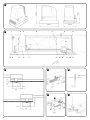
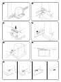

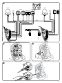

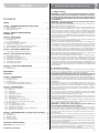
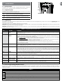

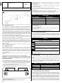


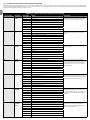
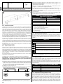


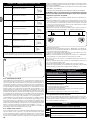
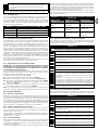
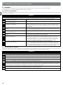
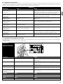

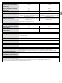

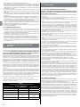


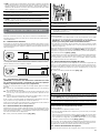
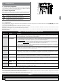
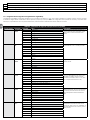
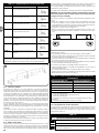
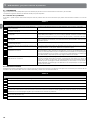
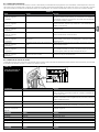


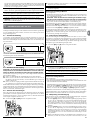
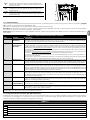


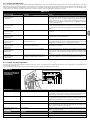
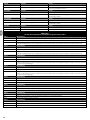
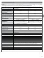


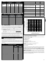
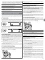

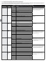

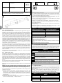

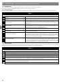

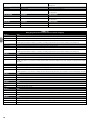


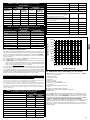

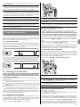
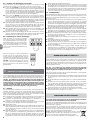
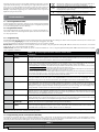
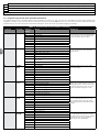
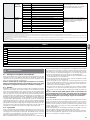
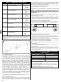

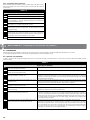

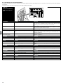
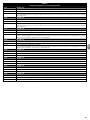
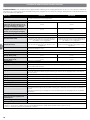
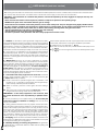
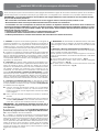
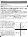
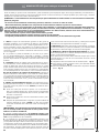
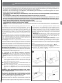
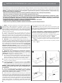
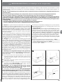


![ES400 User Guide [Polish] (P/N 72E-136310](http://vs1.manualzilla.com/store/data/006874997_1-3b92fe2897ead48327dbddbbb3492fd4-150x150.png)