1
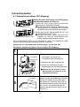
0801874HC4906
PHOTOVOLTAIC INVERTER
MODEL
PV-PNS03ATL-GER
PV-PNS04ATL-GER
PV-PNS06ATL-GER
Installationshandbuch
Deutsch
pp.1-28
Installation Manual
English
pp.29-56
PHOTOVOLTAIC INVERTER
MODEL
English
PV-PNS03ATL-GER
PV-PNS04ATL-GER
PV-PNS06ATL-GER
Installation Manual
pp.1-48
pp.1-48
The photovoltaic inverter (PV inverter) PV-PNS03ATL-GER / PVpp.1-48
PNS04ATL-GER / PV-PNS06ATL-GER is designed to the regulations
stipulated in DIN VDE 0126-1-1. Therefore, the owner may use the PV inverter
only in countries or areas where such regulations are applicable.
Table of Contents
Page
1 Introduction • • • • • • • • • • • • • • •
2 Safety Precautions • • • • • • • • • •
3 Appearance • • • • • • • • • • • • • • •
3.1 Dimensions • • • • • • • • • • •
3.2 Internal Configuration • • • •
4 Included Components and Parts
• • • • • • • • • • • • • • • • • • • • • • • • • • • • •
• • • • • • • • • • • • • • • • • • • • • • • • • • • • •
• • • • • • • • • • • • • • • • • • • • • • • • • • • • •
• • • • • • • • • • • • • • • • • • • • • • • • • • • • •
• • • • • • • • • • • • • • • • • • • • • • • • • • • • • •
5 Required Components, Equipment and Tools
6 Requirements
31
• 32
• 33
• 33
• 33
• • • • • • • • • • • • • • • • • • • • • • • • • • • • • •
• • • • • • • • • • • • • • • • • • • •
• • • • • • • • • • • • • • • • • • • • • • • • • • • • • • • • • • • • • • • •
34
35
36∼39
6.1 Installation Location • • • • • • • • • • • • • • • • • • • • • • • • • • • • • • • 36∼38
6.2 Requirements for Connection to PV Module • • • • • • • • • • • • • • • • • 39
6.3 Requirements for Connection to Grid • • • • • • • • • • • • • • • • • • • • • • 39
7 Installing PV Inverter
8 Connecting Cables
• • • • • • • • • • • • • • • • • • • • • • • • • • • • • • • • • • •
40∼41
• • • • • • • • • • • • • • • • • • • • • • • • • • • • • • • • • • • •
42∼48
8.1 PV Module (DC Input) Connection
8.2 Connection of AC Output
8.3 Actions After Connection
• • • • • • • • • • • • • • • • • • • • •
• • • • • • • • • • • • • • • • • • • • • • • • • • • •
42∼45
46∼47
48
• • • • • • • • • • • • • • • • • • • • • • • • • • • • • • •
9 Test Run • • • • • • • • • • • • • • • • • • • • • • • • • • • • • • • • • • • • • • • • • • • • 49∼52
9.1 Check Before Turning On • • • • • • • • • • • • • • • • • • • • • • • • • • • • • • • 49
9.2 Test Run Procedure
9.3 Troubleshooting
• • • • • • • • • • • • • • • • • • • • • • • • • • • • • • •
49∼50
• • • • • • • • • • • • • • • • • • • • • • • • • • • • • • • • • •
51∼52
10 Precautions for Maintenance
• • • • • • • • • • • • • • • • • • • • • • • • • • • • •
53∼54
11 Appendix • • • • • • • • • • • • • • • • • • • • • • • • • • • • • • • • • • • • • • • • • • • 55∼56
11.1 Selecting Screws • • • • • • • • • • • • • • • • • • • • • • • • • • • • • • • • • • • • 55
11.2 Selecting Cables • • • • • • • • • • • • • • • • •
11.3 Crimping Terminals and Crimping Tools
30
• • • • • • • • • • • • • • • •
55∼56
56
• • • • • • • • • • • • • • • • • • •
1 Introduction
English
The PV inverter PV-PNS03ATL-GER / PV-PNS04ATL-GER / PV-PNS06ATLGER converts direct-current energy generated by PV modules into alternatingcurrent energy for supplying the grid. This Installation Manual illustrates the
installation procedure for the PV inverter, the connection procedurepp.1-48
for the PV
module and grid, and test running of the PV inverter. Operation of the PV
inverter PV-PNS03ATL-GER / PV-PNS04ATL-GER / PV-PNS06ATL-GER is
illustrated in the separate "PHOTOVOLTAIC INVERTER PV-PNS03ATL-GER
/ PV-PNS04ATL-GER / PV-PNS06ATL-GER Operation Manual". pp.1-48
The PV inverter PV-PNS03ATL-GER / PV-PNS04ATL-GER / PV-PNS06ATL-GER
complies with the regulations stipulated in EMC and Low Voltage Directives. It
also meets the provisions defined in DIN VDE 0126-1-1.
pp.1-48
31
2 Safety Precautions
Only qualified technicians may work on the PV
inverter. The installer may work on the PV inverter
only when the power sources are disconnected at
the alternating- and direct-current sides.
●The following symbols denote the type and degree of danger that may result from incorrect use.
WARNING
Alerts you to potential death or
serious injury anticipated if worked
on the PV inverter in a wrong manner.
Do not touch any part of the system with wet hands or body.
Electric shock may result. High voltages are present among the PV
module array cables.
Prohibited
Do not install the PV inverter outdoors.
Fire or electric shock may result.
Never install, disassemble or modify the PV inverter in ways
other than those illustrated in the installation manual.
Do not disassemble
or modify
Falling, electric shock or fire may result.
Always disconnect the power sources at the alternating- and direct-current
sides before performing maintenance. Always wait for 30 minutes to discharge
the capacitors built in the PV inverter before opening its front panel.
Electric shock may result.
Connect the earth lead securely.
Fire or electric shock may result.
Important
Wear insulated rubber gloves for low-voltage operations when wiring PV inverter.
Electric shock may result.
Securely press-fit to tighten crimp terminals with specified
torques on lead wires.
Fire may result.
32
3 Appearance
3.1 Dimensions
■Location of mounting holes
147
170
420
491.7
500
300
110
4×φ7
Unit: mm
3.2 Internal Configuration
The figure below shows the internal configuration and connections with the
front panel removed.
1 Reactor area
pp.1-48
2 Controller area
1
3 DC - terminal
4 DC + terminal
5 AC output terminal
6 Earth terminal
2
pp.1-48
7 AC cable gland
3
8 DC - cable gland
9 DC + cable gland
4
0 Modular jack for RS485 interface
A RS485 interface gland
5
B RS485 switch
pp.1-48
6
+ + +
- - 0
DC
DC
AC
Nmber of input Nmber of
ON
L N
Model
OFF
B
A
7
8
PV-PN03ATL-GER
PV-PN04ATL-GER
PV-PN05ATL-GER
9
33
in DC terminal DC cable glands
2
4
3
6
English
110
210
45
287
4 Included Components and Parts
The PV inverter PV-PNS03ATL-GER / PV-PNS04ATL-GER / PV-PNS06ATL-GER
should be packaged with the following components and parts. Please use the
following table to make sure that all items are included.
1 PV inverter
3 Protective tube (φ20)( x3)
4 Protective tube (φ10)( x6)
2 Mounting plate
5 Cable tie (x7)
6 Operation Manual
Operation
Manual
8 Cable Diameter Check Sheet
Cable
Diamet
er Che
6mm
No.
1
2
3
4
5
6
7
8
9
7 Installation Manual
Installat
ion Manu
al
9 Crimping terminals (x18)
(Ring type)
ck She
et
Item
PV inverter
Mounting plate
Protective tube (φ20)
Protective tube(φ10)
Cable tie
Operation Manual
Installation Manual (This publication)
Cable Diameter Check Sheet
Crimping terminals (2.5mm2x9,6mm2x9)
34
Quantity
1
1
3
6
7
1
1
1
18
Yes
5 Required Components, Equipment and Tools
Electrical System Connection Diagram
(for two string system)
※The illustration shows the case where two strings have one DC disconnector each.
PV inverter
String 1
PV module
2 AC cable
4 AC disconnector
- +
3 DC disconnector
For safety installation and
maintenance work, always
provide a DC disconnector(s)
in your electrical system.
1 DC cable
Earth lead
Parts to be procured
1
2
3
4
DC cable
AC cable
DC disconnector
AC disconnector
5
PV inverter mounting screw
See p 55
See p.56
pp.1-48
Select appropriate screws
for wall
material. See p.55 for details.
* Crimping terminals need be procured if you use 10mm2 cable.
Equipment and tools for electric work
Nippers
Pliers
Phillips screwdriver
Crimping tool (as specified by the manufacturer)
Output measuring instrument
Tester
Earth Tester
(for ranges higher than 700 VDC)
* Prepare any required items other than the above.
35
pp.1-48
pp.1-48
English
String 2
6 Requirements
Before beginning installation of the PV inverter PV-PNS03ATL-GER / PV-PNS04ATLGER / PV-PNS06ATL-GER, make sure that the following requirements are met.
6.1 Installation Location
Selecting and preparing installation location
When installing the PV inverter, follow the requirements below to achieve
optimum performance of, and to ensure safe use of the PV inverter.
●Install the PV inverter indoors. It is PROHIBITED to install the PV inverter
in places unable to be separated from outdoor environment, such as
garage open at one side (i.e., no wall or door able to block such side,
provided).
●Mount the PV inverter horizontally on a firm and sturdy vertical wall
strong enough to bear its weight. If the wall is not strong enough, shore
up the wall. (The PV-PNS03ATL-GER / PV-PNS04ATL-GER weights
19kg; PV-PNS06ATL-GER 20kg. (incl. mounting plate))(See p.55.)
●Ambient temperature: -25-60℃; humidity within 30-90%. Mount the PV
inverter inside the building where no possible condensation due to temperature change occurs.
●Avoid direct sunlight. (Extremely high temperature deteriorates its performance.)
●Install the PV inverter at a place lower than 1,500 m above sea level.
●As illustrated below provide enough space around the PV inverter to
ensure proper cooling capability and room to facilitate maintenance. (For
installing two or more PV inverter, see p.38.)
150 or wider
Front
1,000 or wider
150 or
wider
150 or
wider
500 to 2,000
Unit: mm
36
CAUTION
Do not install the PV inverter in the following places:
(Otherwise, the PV inverter may fail or its safe use may be impeded.
The product warranty shall also be voided.)
・Places where it is exposed to direct sunlight
・Narrow places lacking ventilation
・Places where it is exposed to water
・Places where humidity is significantly high such as lavatory or bathroom
・Places where excessive steam, oil vapor, smoke, dust, or corrosive substance is present
・Places where it is exposed to oily smoke, such as a kitchen
・Places where explosive or flammable gases are present
・Places installations are exposed to vibration or shock
・Places in the vicinity of flammable materials
・Places with unusual conditions other than those indicated above (such as
seafaring vessels or motor vehicles)
・Places where damage from salt air could occur
pp.1-48
Note
Avoid installing the PV inverter in the following places:
pp.1-48
(Otherwise, the PV inverter might cause appliances to generate noises.)
・Places where noises or electric noises are under strict control
・Places in the vicinity of television or radio antennas or cables
pp.1-48
37
English
・Outdoors, or places similar to outdoors (※It is PROHIBITED to install the
PV inverter in places unable to be separated from outdoor environment,
such as garage open at one side, no wall or door able to block such side,
provided.)
(Precautions for installing more than one PV inverter)
●Install the PV inverters in a transverse direction with space between
them as follow.
●Since overall heat divergence is larger than that when one PV inverter is
installed, the gap between the installed PV inverters must be fully kept.
The PV inverter generates heat as it generates electric power while discharging the heated air from the ventilation (or exhaust) opening on its left
side. If PV inverter 'B' is installed immediately to the right of PV inverter 'A',
hot air released from 'B' could affect 'A', resulting in lower cooling performance.
B
A
Hot air
○
Hot air
(Right)
0 or wider
200
or wider
×
(Wrong)
Lateral distance between PV inverters
Longitudinal distance between PV inverters
Unit: mm
38
6.2 Requirements for Connection to PV Module
Up to three strings are connectable to the PV inverter.
●Make sure that the sizes and requirements for the PV modules you are
connecting meet the DC input requirements for the PV inverter. (Active
modules must satisfy the following DC input requirements.)
3250W
4300W
6000W
12.0A DC
18.0A DC
●Do not connect the PV modules with an earthed DC+ or DC- electrode to
the PV inverter. (The safety device specified in DIN VDE 0126-1-1 is activated and the PV inverter does not work.)
●A DC disconnector must always be inserted between the PV inverter and
connected PV modules to avoid electric shock during installation of, or
maintenance work on, the PV inverter.
6.3 Requirements for Connection to Grid
pp.1-48
For connection of the PV inverter to the grid, the relevant technical regulations, as well as specific requirements defined by the local utility company,
must also be complied with.
pp.1-48
●Make sure that the grid to which you are connecting the PV inverter
meets
the requirements as follows.
Voltage range
Frequency range
Connection requirements
184−264.5 V
47.5−50.2 Hz
pp.1-48
●In order to minimize power losses, cables with cross sectional area appropriate to their lengths must be used.
●An AC disconnector must always be inserted between the grid and the PV
inverter.
39
English
DC Input Requirements
PV-PNS03ATL-GER
Recommended generator power PV-PNS04ATL-GER
PV-PNS06ATL-GER
Max. DC voltage (per string)
700 VDC
Min. DC voltage (per string)
150 VDC
PV-PNS03ATL-GER
Max. input current
PV-PNS04ATL-GER
(sum of each string)
PV-PNS06ATL-GER
7 Installing PV Inverter
The following illustrates the installation of the PV inverter.
<Installing the mounting plate>
●Select appropriate screws for wall material. (See p. 55 "Appendix" for
details.)
Screw
(tentatively-fasten)
1. Tentatively fasten one screw in the
top center hole of the mounting
plate.
●The screw should be perpendicular
to the wall.
1
Mounting hole
2. Hang the mounting plate on the tentatively-fastened screw. Adjust the
mounting plate vertically.
1. Tighten six screws in the remaining
mounting holes to fix the plate on the
wall.
2
3
2. Tighten the tentatively-fastened
screw.
Make sure that the mounting plate is on the level.
40
<Mounting the PV Inverter>
1. Remove two screws from the bottom
of the PV inverter.
1
English
PV inverter
Screw
Overhang
PV inverter
1. Securely place the overhang in the
upper section of the back of the PV
Groove
inverter into the groove of the mounting plate.
2. Fix the PV inverter on the mounting
plate with two screws which were
removed in 1-1.
pp.1-48
2
●Tightening torque:1.4-1.6 N・m
Screw
3
pp.1-48
Mounting
plate
Make sure that the PV inverter does not jounce on the mounting plate
or wall.
pp.1-48
41
8 Connecting Cables
8.1 PV Module (DC Input) Connection
Perform the following procedure before connecting the DC input to the PV inverter.
1. Check polarities and maximum voltage of
each PV module string.
●Very dangerous high direct-current voltage
is present on the PV module. Follow safety
precautions to the fullest.
(PV-PNS03ATL-GER)
2. Make sure that AC and DC disconnectors are off.
●Take care not to allow to turn on the AC and DC
(PV-PNS04ATL-GER / PV-PNS06ATL-GER)
disconnectors unexpectedly during operation.
The nember of the input terminals differs between PV-PNS03ATL-GER and
PV-PNS04ATL-GER / PV-PNS06ATL-GER.
Follow the procedure below to connect the cables extending from the
PV module (DC input).
1
Turn off the DC disconnector.
②
Front panel
① Remove the two screws fixing the
front panel from the bottom.
② Remove the front panel.
③
2
③ Also, remove the earth lead from
the earth tab terminal.
Earth lead
①
●Pick up the resin-coated section of
earth lead, pull it to the direction
indicated in the illustration.
Earth
tab
terminal
Screw
Cable diameter check sheet
3
6mm
DC Cable
Check the cable diameter of a DC cable
using the accessory cable diameter
check sheet. Insert the DC cables into
the hole of the cable diameter check
sheet. This determines whether its diameter is smaller or larger than 6mm.
(Different connection method for different
cable diameter. See p.44-6.)
42
DC - terminal
4
DC + terminal
DC
DC
Run the PV module (DC input) cable
extending from the DC disconnector
through the DC cable gland (of smaller
diameters) in the lower section of the
PV inverter.
※To run two or more cables, first
loosen the cable gland and then
remove the protective cap.
DC - Cable
Protective cap
Core lead
approx. 1 mm
5
DC - cable (Silver gray)
gland
Securely attach crimping terminals ,
suited to the cable diameter, to the DC
cables respectively. (See p.56
"Appendix".)
Press-fit mark
DC + cable
pp.1-48
pp.1-48
pp.1-48
43
English
DC + Cable DC + cable (Black) gland
DC cable gland
(of smaller diameter)
For DC cables > 6mm
1. Remove the cord clip.
DC - terminal
DC + terminal
2. Run the DC cable through the protective tube (φ10).
3. Tie up the tube with the cable tie,
with the DC cable held therein.
4. Fix the DC cable on the terminal.
●Tightening torque:
:2.6-3.4 N・
・m
●Avoid confusing the DC + with the
DC - cable.
●Ensure that the protective tube is
installed. This is required to prevent the cable from being damaged
or arrest the spread of possible fire.
Cord clip
Cable tie
Protective tube
Cord clip
6
For DC cables ≦ 6mm
1. Remove the cord clip.
DC - terminal
DC + terminal
2. Run the DC cables in a bundle
through the protective tube (φ20).
3. Install the DC cables on the terminal.
:2.6-3.4 N・
・m
●Tightening torque:
●Avoid confusing the DC + with the DC
- cable.
Protective tube
4. Fasten the cord clip around the protective tube in which the cables are held.
Cord clip
●Tightening torque:
:1.4-1.6 N・
・m
●Ensure that the protective tube is
installed. This is required to prevent the cable from being damaged
or arrest the spread of possible fire.
44
Fasten the DC cable glands.
DC - terminal DC + terminal
●Tightening torque:3 N・m
●Avoid exerting tension on the cables.
7
DC - terminal DC + terminal
Turn on the DC disconnector, and then
check for the correct voltage between
terminals DC + and DC - on the DC
input terminal.
●Make sure the voltage is of 200 to 700V.
8
pp.1-48
Make sure that the protective cap remains on the unused cable gland.
9
Turn off the DC disconnector.
10
pp.1-48
pp.1-48
45
English
DC Cable gland
8.2 Connection of AC Output
Perform the following procedure before connecting the PV inverter to
the AC output.
1. Check the grid for the correct voltage.
●Make sure the voltage is of 184 to 264.5V.
2. Make sure that AC and DC disconnectors are off.
●Take care not to allow any power to flow unexpectedly during operation.
Perform the following procedure to connect the AC cable to the PV inverter.
Core lead
approx. 1 mm
Press-fit mark
2. Assuredly install the crimping terminal on the earth (PE) conductor.
LN
1
1. Run the AC cable through the AC
cable gland (of larger diameter) on
the bottom of the PV inverter, then
firmly attach a crimping terminal.
●Avoid confusing AC and DC cables.
AC cable
AC cable gland
(of larger diameter)
AC output terminal
L
2
Protective
tube
L N
N
Run the AC cables and earth (PE)
conductor through the protective tube
(φ20) and connect cables L and N to
terminals L and N of the AC output
respectively.
●Avoid confusing phase L with phase
N.
PE ●Tightening torque:2.6-3.4 N・m
46
Connect the earth (PE) conductor to
the earth terminal ( ), on the right
side of the AC output terminal, of the
Earth terminal
L N
3
PV inverter.
●Tightening torque:0.9-1.1 N・m
Earth conductor
L N
4
●Ensure that the protective tube is
installed. This is required to prevent
the cable from being damaged or
arrest the spread of possible fire.
Cable tie
L N
Fasten the AC cable gland.
●Tightening torque:5 N・m
5
AC cable gland
pp.1-48
L N
6
PE
Turn on the AC disconnector, and then
check for the correct voltage across
the terminals L-N and L-PEon the AC
side.
●Make sure the voltage is of pp.1-48
184 to
264.5V.
pp.1-48
7
Turn off the AC disconnector.
47
English
Bind the protective tube with the
accessory cable tie with the AC cables
held therein.
Protective tube
8.3 Actions After Connection
1
Fasten the AC cable gland and DC (+ and -) cable glands, so that the
openings are tightly closed.
① Hook to securely mount the front
panel on the PV inverter. Connect
the earth lead under the panel to
Earth tab
the earth tab terminal.
Front
panel
①
terminal
①
2
●Close the panel avoiding jamming.
② Fasten the two screws on the bottom of the panel.
●Tightening torque: 0.9-1.3 N•m
Earth lead
②
Screw
48
9 Test Run
The following illustrates the test run of the PV inverter.
9.1 Check Before Turning On
●The AC cable has been correctly connected.
●All of the DC cables extending from the strings have been connected.
Also, any and all unused cable glands are closed with protective caps on
the bottom of the PV inverter.
English
●The front panel is securely attached to the PV inverter.
9.2 Test Run Procedure
Liquid crystal display(LCD)
The following procedure should
be performed after making sure
that your PV modules are receiving light and no blackout is
POWER
encountered.
MODE
switch
switch
ERROR
LED
SELECT
switch
ENTER
switch
1 Turn on the DC disconnector.
LCD
Check/Action
pp.1-48
Wait for 20 seconds. Then the display
shown to the left should appear on the LCD.
(If no information is displayed, see p.51
"Troubleshooting".)
pp.1-48
pp.1-48
49
2 Turn on the AC disconnector.
LCD
Check/Action
1. Press the POWER switch for 2 seconds
or longer, and then make sure that the
information is displayed informing you
that the PV inverter is starting up.
START
(If the ERROR LED lights up or an error
code is or has been displayed on the
LCD, see p.51 "Troubleshooting".)
RUNN I NG
0 kWh
2. Wait for about 5 minutes until the inverter
becomes active. Check whether or not the
LCD displays the power generation level.
3 Finish the test run.
LCD
Check/Action
1. Press the POWER switch for 2 seconds
or longer, and then make sure that information shown on the left (----) is displayed on the LCD.
2. Turn the AC and DC disconnectors off.
50
9.3 Troubleshooting
The PV inverter has a self-diagnostic system built in, automatically displaying
any failure detected on the LCD. This means that the owner can be quickly
notified of any failure of the PV inverter itself but will also be informed if the
PV system and/or PV inverter has been erroneously installed.
Symptoms
LCD
Check/Action
●The PV module voltage is not
(properly) applied to the DC input
terminal of the PV inverter.
An error message is displayed on the
LCD or the
ERROR LED is
on.
●Check for any error message (or
error code) displayed on the LCD
and then follow the instructions.
●The DC disconnector is off.
ERROR E -**
If the following error message is displayed, follow the instructions.
LCD
ERROR E - 6 6
BLACKOUT
Remedy pp.1-48
Error
Grid is defective Check that the voltage among
or incorrectly
terminals L and N falls someconnected.
where between 184-264.5 VAC. If
erratic voltage is detected, check
pp.1-48
the wiring for correctness.
There is a power Check that the AC disconnector
outage in the
is off.
grid, or the AC
pp.1-48
disconnector.
51
English
No information is displayed on the
LCD.
LCD
ERROR E - 2 0
Error
Remedy
Voltage higher
than 700 VDC is
fed.
Too many PV modules are connected to each other in series.
Adjust the number of modules to
a proper level.
Earth fault is
experienced.
Check that both the PV modules
and wiring are properly isolated.
Make sure that the grid is correctly connected to terminals L and
N.
ERROR E - 2 9
ERROR E - 3 5
None
Poor connection The PV inverter must be fixed.
on the termiContact your dealer.
nal(s) has burnt
out the thermal
fuse.
Insufficient voltage is fed to the
PV inverter, or
the DC disconnector(s) is off.
No information is displayed when
the PV modules are not receiving
light such as in the morning or
nighttime. This is normal.
●Make sure that DC cables are
correctly connected to the terminals (+) and (-).
●Make sure that the disconnector(s) is on.
If the above does not resolve the problem, or errors which are not
covered here are experienced, contact your dealer.
52
10 Precautions for Maintenance
WARNING
High direct-current voltage is applied on the PV inverter from your PV module.
The front panel of the PV inverter may only be opened by qualified technicians.
<Opening the front panel>
2
3
English
1
Turn off the AC disconnector.
Turn off the DC disconnector.
Wait for 30 minutes.
●This is required for the capacitors built in the PV inverter to discharge.
① Remove the two screws fixing the
front panel from the bottom.
②
Front panel
② Remove the front panel.
pp.1-48
③ Also, remove the earth lead
from the
earth tab terminal.
③
4
Earth lead
①
Earth
tab
terminal
●Pick up the resin-coated section of
earth lead, pull it to the direction indicated in the illustration.
pp.1-48
Screw
pp.1-48
53
<Closing the front panel>
1
Make sure that AC and DC disconnectors are off.
① Hook to securely mount the front
panel on the PV inverter. Connect
the earth lead under the panel to the
Earth tab
earth tab terminal.
Front
panel
①
terminal
①
2
●Close the panel avoiding jamming.
② Fasten the two screws on the bottom of the panel.
●Tightening torque: 0.9-1.3 N•m
Earth lead
②
Screw
54
11 Appendix
11.1 Selecting Screws
Each screw must bear at least 1176[N] of load when mounting the PV inverter on the wall. The locations and the type of the screw should be properly
selected. Choices include the following:
Drill hole
Panel thickness
≧18mm
50mm
Screw
Screw
Plug
Drill hole
Block compressive strength
φ5
55mm
Manufacturer: fischerwerke
Product: Universal plug UX
Type: UX6×50mm
φ6
≧11.7N/mm2
≧60mm
Block thickness
55mm
Φ5
2. For walls made of concrete
Screw
Plug
pp.1-48
11.2 Selecting Cables
1. DC cable
DC cables should meet the following specifications. Cables suited to the extent of voltage and current generated on the PV modules you are connecting should be selected.
pp.1-48
PV-PNS03ATL-GER PV-PNS04ATL-GER PV-PNS06ATL-GER
voltage
(per string)
Max. 700 VDC
current
Max. 12A DC
(sum of each string)
Configuration
Conductor cross section
External diameter
Max. 18A DC
1-conductor
2.5∼10mm2
φ4.5∼10mm
55
pp.1-48
DC cable
English
φ5
50mm
φ3
Screw
Φ5
1. For walls made of wood
2. AC Cable
AC cables should meet the following specifications. Cables suited to the
maximum output of the PV modules you are connecting should be selected.
voltage
current
PV-PNS03ATL-GER PV-PNS04ATL-GER PV-PNS06ATL-GER
230 VAC
Max. 13.0A Max. 15.2A Max. 21.7A
3-conductors
Configuration
Conductor cross section 2.5∼6mm2
External diameter φ11∼17mm
2.5∼10mm2
φ11∼20mm
AC cable
11.3 Crimping Terminals and Crimping Tools
Crimping terminals suited to the diameter of the cable conductor should be
applied. Typical terminals include the following:
Manufacturer: Gustav Klauke GmbH
Crimping tool type
Conductor cross section Crimping terminal type
10mm2
K16,K50
6525,6526
4∼6mm2
K10,K14,K15,K50,K82,K85
6505,6506
2.5mm2
K10,K14,K15,K50,K81,K82,K85
6305,6306
The terminal built in the inverter is available to the crimping terminals
of the following dimensions.
Dimensions of the applicable head of the crimping terminal
Dimension
φD
W
Applicable range
≧ 5.1mm
≦ 11mm
Crimping terminal
W
φD
56
Jun. 2008
MODELL
PV-PNS03ATL-GER
PV-PNS04ATL-GER
PV-PNS06ATL-GER
Installationshandbuch
Der Solar-Wechselrichter (PV-Inverter) PV-PNS03ATL-GER / PVPNS04ATL-GER / PV-PNS06ATL-GER entspricht den Anforderungen der
DIN VDE 0126-1-1. Daher der dieser Wechselrichter nur in Ländern verwendet werden, in denen diese Richtlinie gilt.
Deutsch
SOLARSTROM-WECHSELRICHTER
Inhaltsverzeichnis
Seite
1 Einführung • • • • • • • •
2 Sicherheitshinweise •
3 Erscheinungsbild • • •
3.1 Abmessungen •
3.2 Interner Aufbau
4 Zubehör und Teile • •
• • • • • • • • • • • • • • • • • • • • • • • • • • • • • • • • • • • • • •
• • • • • • • • • • • • • • • • • • • • • • • • • • • • • • • • • • • • • •
• • • • • • • • • • • • • • • • • • • • • • • • • • • • • • • • • • • • • •
• • • • • • • • • • • • • • • • • • • • • • • • • • • • • • • • • • • • • •
• • • • • • • • • • • • • • • • • • • • • • • • • • • • • • • • • • • • • • •
5 Erforderliche Teile, Ausrüstung und Werkzeuge
6 Anforderungen
3
•4
•5
•5
•5
• • • • • • • • • • • • • • • • • • • • • • • • • • • • • • • • • • • • • • •
• • • • • • • • • • • • • • • • • • • •
• • • • • • • • • • • • • • • • • • • • • • • • • • • • • • • • • • • • • • • •
6
7
8∼11
6.1 Installationsort • • • • • • • • • • • • • • • • • • • • • • • • • • • • • • • • • • • • 8∼10
6.2 Anschluss an Solarzellen • • • • • • • • • • • • • • • • • • • • • • • • • • • • • • • 11
6.3 Anschluss an ein Netz • • • • • • • • • • • • • • • • • • • • • • • • • • • • • • • • • 11
7 Installation des Solarstrom-Wechselrichters
8 Anschlusskabel
• • • • • • • • • • • • • • • • • •
12∼13
• • • • • • • • • • • • • • • • • • • • • • • • • • • • • • • • • • • • • •
14∼20
8.1 Solarzellenanschluss (DC-Eingang)
8.2 Anschluss AC-Ausgang • • • • • •
8.3 Nach dem Anschluss der Kabel
• • • • • • • • • • • • • • • • • • • •
• • • • • • • • • • • • • • • • • • • • • • •
14∼17
18∼19
20
• • • • • • • • • • • • • • • • • • • • • • • • • •
9 Probelauf • • • • • • • • • • • • • • • • • • • • • • • • • • • • • • • • • • • • • • • • • • • 21∼24
9.1 Tests vor Inbetriebnahme • • • • • • • • • • • • • • • • • • • • • • • • • • • • • • • 21
9.2 Probelauf starten
• • • • • • • • • • • • • • • • • • • • • • • • • • • • • • • • •
9.3 Problembeseitigung
• • • • • • • • • • • • • • • • • • • • • • • • • • • • • • •
10 Vorsichtsmaßnahmen bei der Wartung
• • • • • • • • • • • • • • • • • • • • •
21∼22
23∼24
25∼26
11 Anhang • • • • • • • • • • • • • • • • • • • • • • • • • • • • • • • • • • • • • • • • • • • • 27∼28
11.1 Schraubenauswahl • • • • • • • • • • • • • • • • • • • • • • • • • • • • • • • • • • • 27
11.2 Kabelauswahl • • • • • • • • • • • • • • • • • • • • • • • • • • • • • • • • • • • 27∼28
11.3 Kabelösen und Werkzeuge • • • • • • • • • • • • • • • • • • • • • • • • • • • • • 28
2
1 Einführung
Deutsch
Der Solarstrom-Wechselrichter PV-PNS03ATL-GER / PV-PNS04ATL-GER /
PV-PNS06ATL-GER wandelt Gleichstrom erzeugt durch Solarzellen in
Wechselstrom um und speist diesen in ein Stromnetz ein. In diesem
Installationshandbuch werden die Montage des Wechselrichters, der
Anschluss an die Solarzellen und an das Stromnetz, sowie der Testlauf des
Wechselrichters beschrieben. Die Bedienung des Solarstrom-Wechselrichters
PV-PNS03ATL-GER / PV-PNS04ATL-GER / PV-PNS06ATL-GER wird in dem
entsprechenden Kapitel "SOLARSTROM-WECHSELRICHTER PVPNS03ATL-GER / PV-PNS04ATL-GER / PV-PNS06ATL-GER
Bedienungsanleitung" beschrieben.
Der PV-Inverter PV-PNS03ATL-GER / PV-PNS04ATL-GER / PV-PNS06ATL-GER
entspricht den Vorschriften zur elektromagnetischen Verträglichkeit und den
Niederspannungs-Richtlinien. Außerdem werden die Vorschriften der DIN VDE
0126-1-1 abgedeckt.
3
2 Sicherheitshinweise
Der Wechselrichter darf nur von ausgebildeten
Technikern installiert werden. Die
Installationsarbeiten dürfen nur durchgeführt werden,
wenn das Gerät auf der Gleich- und
Wechselstromseite vom Netz getrennt wurde.
● Die folgenden Symbole zeigen den Grad und die Art der Gefährdung,
wenn die Sicherheitshinweise nicht beachtet werden.
WARNUNG
Warnt vor Lebensgefahr oder
schweren Verletzungen, wenn
die Arbeiten am Wechselrichter
falsch durchgeführt werden.
Berühren Sie keine Teile des Systems mit nassen Händen.
Sonst kann es zu einem Stromschlag kommen. Die Kabel der
Solarzellen führen Hochspannung.
Verboten
Installieren Sie den Wechselrichter nicht draußen.
Ein Brand oder ein Stromschlag können die Folge sein.
Bauen Sie den Wechselrichter nicht auseinander oder
modifizieren ihn und installieren Sie ihn nur so, wie im
Installationshandbuch und in den Schaltplänen angegeben.
Nicht
Das Gerät kann herunterfallen und ein Stromschlag oder ein Brand
auseinanderbauen
oder modifizieren kann die Folge sein.
Trennen Sie das Gerät immer vom Gleich- und Wechselstromnetz, wenn Sie
Wartungsarbeiten durchführen. Warten Sie 30 Minuten, bis sich die
integrierten Kondensatoren entladen haben, ehe Sie die Frontplatte öffnen.
Sonst kann es zu einem Stromschlag kommen.
Schließen Sie das Massekabel fest an.
Ein Brand oder ein Stromschlag können die Folge sein.
Wichtig
Tragen Sie bei den Verkabelungsarbeiten des Wechselrichters
isolierte Gummihandschuhe für Niederspannungen.
Sonst kann es zu einem Stromschlag kommen.
Pressen Sie die Kabelösen mit dem erforderlichen Druck auf
die Stromkabel.
Ein Brand kann die Folge sein.
4
3 Erscheinungsbild
3.1 Abmessungen
300
147
170
4×φ7
110
420
500
491,7
110
210
45
287
Maßeinheit: mm
3.2 Interner Aufbau
Die nachstehende Abbildung zeigt den internen Aufbau und die Anschlüsse
bei abgenommener Frontplatte.
1
2
3
4
5
6
7
8
9
0
A
B
1
2
3
4
5
0
ON
- - DC
+ + +
L N
DC
AC
OFF
B
A
6
Nummern für DC- Nummern des
Klemmenleiste DC-Kabelstrangs
PV-PN03ATL-GER
2
4
PV-PN04ATL-GER
3
6
PV-PN05ATL-GER
Modell
7
8
Drosselbereich
Reglerbereich
Klemmenleiste DC Klemmenleiste DC +
Klemmenleiste AC-Ausgang
Masseanschluss
AC-Kabelverschraubung
DC(-)-Kabelverschraubung
DC(+)-Kabelverschraubung
Modulbuchse für RS485-Schnittstelle
RS485-Schnittstellenkabel
RS485-Schalter
9
5
Deutsch
■Befestigungsbohrungen
4 Zubehör und Teile
Der PV-Inverter PV-PNS03ATL-GER / PV-PNS04ATL-GER / PV-PNS06ATL-GER
wird mit dem folgenden Zubehör und den nachstehenden Teilen ausgeliefert.
Prüfen Sie die Lieferung anhand der nachstehenden Liste auf Vollständigkeit.
1 Solarstrom-Wechselrichter
3 Schutzrohr (φ20)( x3)
4 Schutzrohr (φ10)( x6)
2 Montageplatte
5 Kabelbinder (x7)
6 Bedienungsanleitung
Operation
Manual
8 Kabellehre
Cable
Diamet
er Che
6mm
Nr.
1
2
3
4
5
6
7
8
9
Installat
ion Manu
al
9 Kabelösen( x18)
(Ringform)
ck She
et
Teil
Solarstrom-Wechselrichter
Montageplatte
Schutzrohr (φ20)
Schutzrohr (φ10)
Kabelbinder
Bedienungsanleitung
Installationshandbuch (dieses Dokument)
Kabellehre
Kabelösen (2,5mm2x9・6mm2x9)
6
7 Installationshandbuch
Anzahl
1
1
3
6
7
1
1
1
18
Ja
5 Erforderliche Teile, Ausrüstung und Werkzeuge
Schaltplan
Solarstrom-Wechselrichter
String 1
Solarzelle
2 AC-Kabel
String 2
4 AC-Trennschalter
- +
3 DC-Trennschalter
Bauen Sie zur Sicherheit bei
der Installation und bei
Wartungsarbeiten DCTrennschalter in Ihr System ein.
1 DC-Kabel
Massekabel
Beizustellende Teile
1
2
3
4
DC-Kabel
AC-Kabel
DC-Trennschalter
AC-Trennschalter
Siehe Seite 27
Siehe Seite 28
5
Befestigungsschrauben
Wechselrichter
Wählen Sie die Schrauben nach den für die Wand verwendeten Materialien. Details finden Sie auf Seite 27.
* Bei Verwendung von 10 mm2 Kabel müssen Kabelöse gekauft werden.
Zubehör und Werkzeuge für Elektroarbeiten
Zwickzange
Zange
Kreuzschlitzschraubenzieher
Crimp-Werkzeug (nach Herstellerangaben)
Ausgangs-Messinstrument
Tester
(für mehr als 700 V DC)
Massetester
* Bereiten Sie alle Teile vor.
7
Deutsch
(für ein Zwei-Stringsystem)
※Die Darstellung zeigt zwei Strings mit jeweils einem DC-Trennschalter.
6 Anforderungen
Stellen Sie vor der Installation des Wechselrichters PV-PNS03ATL-GER / PVPNS04ATL-GER / PV-PNS06ATL-GER sicher, dass die folgenden Anforderungen
erfüllt werden.
6.1 Installationsort
Auswahl und Vorbereitung des Montageplatzes
Achten Sie bei der Installation des Wechselrichters auf die folgenden
Voraussetzungen, damit er optimal und sicher arbeitet.
● Installieren Sie den Wechselrichten in einem Gebäude. Der
Wechselrichter darf NICHT im Außenbereich, wie auf einer Seite offene
Garagen, montiert werden (Der Montageplatz muss durch Türen
gesichert sein..
● Montieren Sie den Wechselrichter waagerecht an einer Wand, die das
Gewicht des Geräts tragen kann. Ist die Wand nicht stark genug, verstärken
Sie die Wand vor der Installation. (PV-PNS03ATL-GER / PV-PNS04ATLGER wiegt 19 kg; PV-PNS06ATL-GER 20 kg. (einschl. Montageplatte)) (Sie
auf Seite 27.)
● Umgebungstemperatur: -25 - 60°C Relative Feuchte 30 - 90%. Montieren
Sie den Wechselrichter im Gebäude an einer Stelle, an der keine
Kondensatbildung durch Temperaturschwankungen auftreten kann.
● Vermeiden Sie direkte Sonneneinstrahlung. (Durch sehr hohe
Temperaturen kann die Leistung sinken.)
● Montieren Sie den Wechselrichter an einem Ort der tiefer als 1.500 m
unter Normal-Null liegt.
● Sorgen Sie um den Wechselrichter für ausreichenden Platz, damit die Kühlung
optimal ist und er einfach gewartet werden kann (Bei einer Installation von
mehreren Inverter finden Sie entsprechende Details auf Seite 10.)
150 oder mehr
Vorderseite
1.000 oder
mehr
150 oder
mehr
150 oder
mehr
500 bis 2.000
Maßeinheit: mm
8
ACHTUNG
Betrieb ist nicht möglich. Außerdem kann die Garantie verfallen.)
・Außen oder Außenbereiche (* NICHT in Bereichen, wie auf einer Seite
offene Garagen, montiert, der Montageplatz muss durch Türen gesichert
sein.
・Stellen mit direkter Sonneneinstrahlung
・Enge Stellen mit schlechter Lüftung
・Stellen, an denen Wasser frei wird
・Stellen mit sehr hoher Luftfeuchtigkeit, wie Waschräume
・Stellen mit Dampf, Ölnebel, Rauch Staub, Salz oder korrosiven
Substanzen
・Stellen mit Öldämpfen, wie Küchen
・Stellen mit explosiven oder brennbaren Gasen
・Stellen, an denen Vibrationen und Stöße auftreten
・Stellen in der Nähe von brennbaren Materialien
・Orten mit nicht normalen Betriebsbedingungen, die oben nicht
beschrieben wurden (beispielsweise Schiffe oder Motorfahrzeuge)
・Stellen mit salzhaltiger Luft
Hinweis
Installieren Sie den Wechselrichter nicht an den folgenden Stellen:
(Anderenfalls kann der Wechselrichter elektrische Störungen hervorrufen.)
・Stellen, an denen elektrische Störungen nicht auftreten dürfen
・Stellen in der Nähe von Fernseh- und Rundfunkgeräten oder Kabeln
9
Deutsch
Installieren Sie den Wechselrichter nicht unter folgenden Bedingungen:
(Anderenfalls kann der Wechselrichter herunterfallen oder rein sicherer
(Vorsichtsmaßnahmen bei der Installation von mehreren Wechselrichtern)
● Installieren Sie die Wechselrichter nebeneinander mit ausreichendem
Abstand.
● Da sich eine größere Hitze entwickelt als bei der Installation von nur
einem Wechselrichter müssen die Zwischenräume belüftet werden.
Bei der Stromerzeugung gibt der Wechselrichter Wärme ab, die durch die
Lüftungsöffnung (oder Absaugung) an der linken Seite austritt. Ist der
Wechselrichter 'B' direkt rechts vom Wechselrichter 'A' installiert kann die
von 'A' freiwerdende Wärme die Leistung von 'B' beeinträchtigen.
B
A
Heiße
Luft
○
Heiße
Luft
(Rechts)
0 oder mehr
200
oder mehr
×
(Falsch)
Seitlicher Abstand zwischen den Wechselrichtern
Senkrechter Abstand zwischen den Wechselrichtern
Maßeinheit: mm
10
6.2 Anschluss an Solarzellen
An den Wechselrichter können bis zu drei Strings angeschlossen werden.
DC-Eingang
PV-PNS03ATL-GER
Empfohlene Generatorleistung
PV-PNS04ATL-GER
PV-PNS06ATL-GER
Maximale Spannung (je String)
700 VDC
Minimale Spannung (je String)
150 VDC
PV-PNS03ATL-GER
Max. Strom
PV-PNS04ATL-GER
(Summe aller Strings)
PV-PNS06ATL-GER
3250W
4300W
6000W
12,0A DC
18,0A DC
● Schließen Sie keine Solarzellen mit Masse an DC+ oder DC- an den
Solarstrom-Wechselrichter an. (Die Sicherheitseinrichtung, definiert in DIN
VDE 0126-1-1 spricht an und der Wechselrichter arbeitet nicht.)
● Zur sicheren Arbeit bei Installation und Wartung muss zwischen dem
Wechselrichter und den Solarzellen immer ein DC-Trennschalter angebracht sein.
6.3 Anschluss an ein Netz
Bei dem Anschluss des Wechselrichters an das Netz müssen die entsprechenden örtlich geltenden Vorschriften und Regelungen beachtet werden.
● Achten Sie darauf, dass das Netz, an den Sie den Wechselrichter
anschließen, die folgenden Anforderungen erfüllt:
Spannungsbereich
Frequenzbereich
Voraussetzungen
184−264,5 V
47,5−50,2 Hz
● Es müssen Kabelquerschnitte, die der Kabellänge entsprechen, verwendet werden, um den Leistungsverlust auf ein Minimum zu reduzieren.
● Zwischen dem Netz und de, Wechselrichter muss immer ein ACTrennschalter vorgesehen werden.
11
Deutsch
● Achten Sie darauf, dass die Größe und Spezifikationen der Solarzellen,
die Sie an den DC-Eingang anschließen, den Anforderungen des
Wechselrichters entsprechen. (Aktive Module müssen den folgenden
Gleichstromspezifikationen entsprechen.)
7 Installation des Solarstrom-Wechselrichters
Im Folgenden wird die Installation des Wechselrichters beschrieben.
<Montage der Montageplatte>
●Wählen Sie die Schrauben nach den für die Wand verwendeten Materialien.
(Details finden Sie im "Anhang" auf Seite 27.)
Schraube
(noch nicht fest
angezogen)
1. Drehen Sie die Schrauben in die
obere mittige Bohrung der
Montageplatte, ziehen sie aber noch
nicht fest.
● Die Schraube muss senkrecht zur
Wand ausgerichtet sein.
1
Montagebohrung
2. Hängen Sie die Montageplatte auf
die Schrauben. Justieren Sie die
senkrechte Ausrichtung der
Montageplatte.
1. Drehen Sie jetzt auch die restlichen
sechs Schrauben in die jeweiligen
Montagebohrungen.
2
3
2. Ziehen Sie jetzt die Schrauben fest
an.
Vergewissern Sie sich, dass die Montageplatte waagerecht
ausgerichtet ist.
12
<Montage des Wechselrichters>
1. Entfernen Sie die beiden Schrauben
unten am Wechselrichter.
Deutsch
1
SolarstromWechselrichter
Schraube
Falz
(Aufhängung)
SolarstromWechselrichter
1. Führen Sie die Falz im oberen
Bereich der Rückseite des
Nut
Wechselrichters in die Nut der
Montageplatte. Hierdurch wird der
Wechselrichter von der
Montageplatte gehalten.
2
2. Befestigen Sie den Wechselrichter
mit den in 1-1 entfernten Schrauben
auf der Montageplatte.
● Drehmoment: 1,4-1,6 N・m
Montageplatte
Schraube
3
Achten Sie darauf, dass der Wechselrichter nicht auf der Montageplatte
wackelt.
13
8 Anschlusskabel
8.1 Solarzellenanschluss (DC-Eingang)
Gehen Sie beim Anschluss des DC-Eingangs
des Wechselrichters wie folgt vor.
1. Prüfen Sie die Polung und die maximale
Spannung der Solarzellen-Strings.
(PV-PNS03ATL-GER)
● An den Solarzellen liegt eine gefährlich hohe
Gleichspannung an. Befolgen Sie unbedingt
die erforderlichen Sicherheitsvorkehrungen.
2. Prüfen Sie, ob die Trennschalter für AC und
DV AUSGESCHALTET sind.
● Sorgen Sie dafür, dass während der
Arbeiten AC- und DC-Trennschalter nicht
(PV-PNS04ATL-GER / PV-PNS06ATL-GER)
wieder eingeschaltet werden können.
Für PV-PNS03ATL-GER und PV-PNS04ATL-GER / PV-PNS06ATL-GER
werden unterschiedliche Klemmennummern verwendet.
Folgen Sie den nachstehenden Anweisungen, um die von den
Solarzellen kommenden Kabel anzuschließen (DC-Eingang).
1
Schalten Sie den DC-Trennschalter AUS.
②
Frontplatte
Masseklemme
③
2
① Entfernen Sie die beiden
Schrauben, mit denen die
Frontplatte unten befestigt ist.
② Nehmen Sie die Frontplatte ab.
③ Lösen Sie außerdem das das
Massekabel von der Masseklemme.
Massekabel
①
● Nehmen Sie das isolierte Teil des
Massekabels und ziehen es in die
abgebildete Richtung.
Schraube
Kabellehre
6mm
3
DC-Kabel
Prüfen Sie den Kabelquerschnitt des DCKabels mit Hilfe der Kabellehre. Schieben
Sie das DC-Kabel durch die Öffnung in
der Kabellehre. Hierdurch sehen Sie, ob
der Kabelquerschnitt größer oder kleiner
als 6 mm ist. (Anschlussmethoden für
andere Kabelquerschnitte finden Sie auf
Seite 16-6.)
14
Klemmenleiste Klemmenleiste
DC DC +
DC
※Sollen mehrere Kabel hindurchgeführt werden, lösen Sie
zunächst die Kabelverschraubung
und entfernen dann die
Schutzkappe.
DC-Kabelverschraubung
(kleinerer Durchmesser)
Schutzkappe
Litze
etwa 1 mm
5
DC (+) - Kabel
DC (+) – Kabel DC(+) Kabelverschraubung (schwarz)
DC (-) - Kabel
DC (-) – Kabelverschraubung
(silbergrau)
Versehen Sie die DC-Kabel mit
Kabelösen , die dem
Kabeldurchmesser entspricht. (Siehe
"Anhang" Seite 28)
Pressen Sie auf die Markierung
DC (+) -Kabel
15
Deutsch
4
DC
Führen Sie das Kabel der Solarzellen
(DC-Eingang) vom DC-Trennschalter
durch die DC-Kabelverschraubung
(kleinerer Durchmesser) in den
unteren Bereich des SolarstromWechselrichters.
Für DC-Kabel > 6 mm
1. Entfernen Sie die Kabelklemme.
Klemmenleiste Klemmenleiste
DC DC +
2. Ziehen Sie das DC-Kabel durch das
Schutzrohr (φ10).
3. Befestigen Sie das Rohr mit dem DCKabel mit Hilfe eines Kabelbinders.
4. Schließen Sie das DC-Kabel an die
Klemmenleiste an.
● Drehmoment: 2,6-3,4 N・
・m
● Achten Sie darauf, dass das DC + nicht
mit dem DC – Kabel vertauscht wird.
● Vergewissern Sie sich, dass das
Schutzrohr installiert ist. Dies ist
erforderlich, damit das Kabel nicht
beschädigt wird und Feuer sich
nicht ausbreiten kann.
Kabelklemme
Kabelbinder
Schutzrohr
Kabelklemme
6
Für DC-Kabel ≦ 6mm
Klemmenleiste Klemmenleiste
DC DC +
1. Entfernen Sie die Kabelklemme.
2. Ziehen Sie das DC-Kabel durch das
Schutzrohr (φ20).
3. Schließen Sie das DC-Kabel an die
Klemmenleiste an.
● Drehmoment: 2,6-3,4 N・・m
● Achten Sie darauf, dass das DC +
nicht mit dem DC – Kabel vertauscht
wird.
Schutzrohr
4. Befestigen Sie die Kabelklemme
wieder, so dass das Schutzrohr mit
dem Kabel gehalten wird.
● Drehmoment: 1,4-1,6 N・・m
● Vergewissern Sie sich, dass das
Schutzrohr installiert ist. Dies ist
erforderlich, damit das Kabel nicht
beschädigt wird und Feuer sich
nicht ausbreiten kann.
Kabelklemme
16
Klemmenleiste Klemmenleiste
DC DC +
Befestigen Sie die DCKabelverschraubung
● Drehmoment: 3 N・m
7
Kabel kein Zug ausgeübt wird.
DC-Kabelverschraubung
Klemmenleiste Klemmenleiste
DC DC +
8
Schalten Sie den DC-Trennschalter
EIN und prüfen Sie die Spannung zwischen den Klemmen DC + und DC – auf
der Klemmenleiste des DC-Eingangs.
● Überzeugen Sie sich, dass die
Spannung zwischen 200 und 700 V
liegt.
Achten Sie darauf, dass die Schutzkappen an den nicht verwendeten
9 Kabelverschraubungen vorhanden sind.
Schalten Sie den DC-Trennschalter AUS.
10
17
Deutsch
● Achten Sie darauf, dass auf das
8.2 Anschluss AC-Ausgang
Gehen Sie beim Anschluss des Wechselrichters an den DC-Ausgang
wie folgt vor.
1. Prüfen Sie das Netz auf korrekte Spannung.
● Überzeugen Sie sich, dass die Spannung zwischen 184 und 264,5 V
liegt.
2. Prüfen Sie, ob die Trennschalter für AC und DV AUSGESCHALTET sind.
● Sorgen Sie dafür, dass während der Arbeiten der Stromfluss nicht
wieder eingeschaltet werden kann.
Gehen Sie beim Anschluss des AC-Kabels an den Wechselrichter wie folgt vor.
Litze
etwa 1 mm
Pressen Sie auf die Markierung
LN
1
1. Führen Sie das AC-Kabel durch die
AC-Kabelverschraubung (größrer
Durchmesser) in den unteren
Bereich des SolarstromWechselrichters und bringen dann
eine Kabelöse an.
2. Bringen Sie die beiliegende
Kabelöse an das Massekabel (PE)
an.
● Verwechseln Sie nicht AC- und DC-
AC-Kabel
Kabel.
AC-Kabelverschraubung
(größerer Durchmesser)
Klemmenleiste
AC-Ausgang
L
2
Schutzrohr
L N
N
Führen Sie die AC- und das
Massekabel (PE) durch das
Schutzrohr (φ20) und befestigen Sie
die Kabel L und N an die Klemmen L
und N der Klemmenleiste des ACAusgangs.
● Verwechseln Sie nicht die Phasen L
und N.
PE ● Drehmoment: 2,6-3,4 N・m
18
Schließen Sie das Massekabel (PE)
masseanschluss ( ) rechts neben
der Klemmenleiste des AC-Ausgangs
Masseanschluss
L N
des Wechselrichters an.
● Drehmoment: 0,9-1,1 N・m
Massekabel
Befestigen Sie das Schutzrohr mit den
AC-Kabeln mit einem Kabelbinder.
Schutzrohr
L N
● Vergewissern Sie sich, dass das
4
Schutzrohr installiert ist. Dies ist
erforderlich, damit das Kabel nicht
beschädigt wird und Feuer sich nicht
ausbreiten kann.
Kabelbinder
L N
Befestigen Sie die ACKabelverschraubung
● Drehmoment: 5 N・m
5
AC-Kabelverschraubung
Schalten Sie den AC-Trennschalter
ein und prüfen Sie die Spannung zwischen den Klemmen L-N und L-PE auf
der Klemmenleiste des AC-Ausgangs.
L N
6
PE
● Überzeugen Sie sich, dass die
Spannung zwischen 184 und 264,5 V
liegt.
7
Schalten Sie den AC-Trennschalter AUS.
19
Deutsch
3
8.3 Nach dem Anschluss der Kabel
1
Befestigen Sie die AC – und DC (+ und -) Kabelverschraubungen, damit
sie fest verschlossen sind.
①
① Haken Sie die Frontplatte des
Frontplatte
Wechselrichters wieder ein.
Schließen Sie das Massekabel
wieder an die Masseklemme unter
Masseklemme
der Frontplatte an.
● Schließen Sie die Frontplatte ohne
etwas einzuklemmen.
①
2
Massekabel
② Befestigen Sie die Frontplatte auf
der Unterseite mit den beiden
Schrauben.
● Drehmoment: 0,9-1,3 N•m
②
Schraube
20
9 Probelauf
Im Folgenden wird der Probelauf des Wechselrichters beschrieben.
● Die AC-Kabel wurden korrekt angeschlossen.
● Alle DC-Kabel von den Strings wurden angeschlossen. Außerdem sind
alle nicht benutzten Kabelverschraubungen unten am Wechselrichter mit
Schutzkappen verschlossen.
● Die Frontplatte des Wechselrichters wurde sicher befestigt.
LCD-Anzeige
9.2 Probelauf starten
Wenn Sie sichergestellt haben,
dass die Solarzellenmodule konstant Licht empfangen, gehen Sie
wie folgt vor.
ERRORLED
POWER- MODE- SELECTSchalter Schalter Schalter
ENTERSchalter
1 Schalten Sie den DC-Trennschalter EIN.
LCD
Prüfen/Aktion
Warten Sie 20 Sekunden. Danach sollte die links
dargestellt Anzeige auf der LCD erscheinen.
(Werden keine Informationen angezeigt,
siehe "Problembeseitigung" auf Seite 23.)
21
Deutsch
9.1 Tests vor Inbetriebnahme
2 Schalten Sie den AC-Trennschalter EIN.
LCD
Prüfen/Aktion
1. Drücken Sie den EIN/AUS-Schalter mindestens 2 Sekunden und prüfen Sie, ob
angezeigt wird, dass der Wechselrichter
gestartet wird.
START
(Leuchtet die Fehler-LED oder wird auf
der LCD ein Fehlercode angezeigt, finden
Sie Informationen unter
"Problembeseitigung" auf Seite 23.)
BETR I EB
0 kWh
2. Warten Sie etwa 5 Minuten, bis der
Wechselrichter aktiviert ist. Prüfen Sie, ob
die LCD anzeigt, welcher Strom erzeugt wird.
3 Beenden Sie den Testlauf.
Prüfen/Aktion
LCD
1. Drücken Sie den EIN/AUS-Schalter mindestens 2 Sekunden und prüfen Sie, ob
links auf der LCD (----) angezeigt wird.
2. Schalten Sie den AC- und den DCTrennschalter AUS.
22
9.3 Problembeseitigung
Symptome
LCD
Prüfen/Aktion
Auf der LCD
wird keine
Information
angezeigt.
● Die von den Solarzellen kommende Spannung ist nicht korrekt
an die DC-Klemmenleiste des
Wechselrichters angeschlossen.
● Der DC-Trennschalter ist ausgeschaltet.
Auf der LCD
wird eine
Fehlermeldung
angezeigt oder
die FEHLERLED leuchtet.
● Prüfen Sie ob auf der LCD eine
Fehlermeldung (oder ein
Fehlercode) angezeigt wird und
folgen dann den Anweisungen.
STOERUNG E -**
Wird einer der folgenden Fehler angezeigt, folgen Sie den Anweisungen.
LCD
STOERUNG E - 6 6
NETZAUSFAL L
Fehler
Beseitigung
Netz defekt oder
falsch
angeschlossen.
Prüfen Sie, ob die Spannung
zwischen den Klemmen L und N
bei 184 - 264,5 V AC liegt. Ist die
Spannung nicht korrekt, prüfen
Sie die Verkabelung.
Stromausfall des Prüfen Sie, ob der ACNetzes oder der
Trennschalter ausgeschaltet ist.
AC-Trennschalter
ist nicht
eingeschaltet.
23
Deutsch
Der Solarstrom-Wechselrichter ist mit einem Selbstdiagnosesystem ausgestattet und Fehler werden automatisch auf der LCD angezeigt. Dies bedeutet,
dass Sie schnell über jeden Fehler des Wechselrichters und zusätzlich über
Fehler bei der Installation des System und des Wechselrichters informiert
werden.
LCD
STOERUNG E - 2 0
Beseitigung
Fehler
Spannung
höher als 700 V
DC.
Es sind zu viele Solarzellen in
Serie geschaltet. Konfigurieren
Sie die Solarzellen um.
Massefehler
aufgetreten.
Prüfen Sie, ob Solarzellen und
Verkabelung korrekt isoliert sind.
Prüfen Sie, ob das Netz korrekt
an die Klemmen L und N
angeschlossen ist.
Schlechte
Verbindung an den
Klemmen führte
zum Durchbrennen
der Sicherung.
Der Solarstrom-Wechselrichter
muss repariert werden.
Die Spannung
zum
Wechselrichter ist
zu niedrig oder
der (die) DCTrennschalter ist
ausgeschaltet.
Wenn die Solarzellen morgens oder
nachts kein Licht empfangen, werden keine Informationen angezeigt.
Dies ist normal.
STOERUNG E - 2 9
STOERUNG E - 3 5
None
Wenden Sie sich an Ihren
Händler.
● Vergewissern Sie sich, dass die
DC-Kabel korrekt an die Klemmen
(+) und (-) angeschlossen sind.
● Vergewissern Sie sich, dass der (die)
Trennschalter eingeschaltet ist.
Lassen sich durch diese Vorschläge die Probleme nicht beseitigen
oder wird ein Fehler angezeigt, der hier nicht erwähnt ist, wenden Sie
sich an Ihren Händler.
24
10 Vorsichtsmaßnahmen bei der Wartung
Die Solarzellen versorgen Ihren Solarstrom-Wechselrichter mit einer
gefährlich hohen Gleichspannung. Die Frontplatte des SolarstromWechselrichters darf nur von einem qualifizierten Techniker geöffnet werden.
<Öffnen der Frontplatte>
1
2
3
Schalten Sie den AC-Trennschalter AUS.
Schalten Sie den DC-Trennschalter AUS.
Warten Sie 30 Minuten.
● Hierdurch können sich die Kondensatoren im Wechselrichter entladen.
②
Frontplatte
Masseklemme
③
① Entfernen Sie die beiden
Schrauben, mit denen die
Frontplatte unten befestigt ist.
② Nehmen Sie die Frontplatte ab.
③ Lösen Sie außerdem das das
Massekabel von der Masseklemme.
4
Massekabel
①
● Nehmen Sie das isolierte Teil des
Massekabels und ziehen es in die
abgebildete Richtung.
Schraube
25
Deutsch
WARNUNG
<Schließen der Frontplatte>
1
Prüfen Sie, ob die Trennschalter für AC und DV AUSGESCHALTET
sind.
①
① Haken Sie die Frontplatte des
Wechselrichters wieder ein.
Schließen Sie das Massekabel
wieder an die Masseklemme unter
Masseklemme
der Frontplatte an.
Frontplatte
● Schließen Sie die Frontplatte ohne
etwas einzuklemmen.
①
2
Massekabel
② Befestigen Sie die Frontplatte auf
der Unterseite mit den beiden
Schrauben.
● Drehmoment: 0,9-1,3 N•m
②
Schraube
26
11 Anhang
11.1 Schraubenauswahl
φ5
50mm
φ3
Schraube
Bohrung
Plattendicke
≧18mm
50mm
Φ5
1. Für Holzwände
Schraube
Schraube
Dübel
Bohrung
Druckfestigkeit
φ5
55mm
Hersteller: Fischerwerke
Produkt: Universaldübel UX
Typ: UX 6 × 50 mm
φ6
≧11,7N/mm2
≧60mm
Dicke
55mm
Φ5
2. Für Betonwände
Schraube
Dübel
11.2 Kabelauswahl
1. DC-Kabel
Das DC-Kabel muss den folgenden Spezifikationen entsprechen. Das Kabel
muss entsprechend der von den Solarzellen gelieferten Spannung und
Strom ausgewählt werden.
PV-PNS03ATL-GER PV-PNS04ATL-GER PV-PNS06ATL-GER
Spannung
(pro String)
Strom
(Summe aller Strings)
Konfiguration
Leiterquerschnitt
Außendurchmesser
Max. 700 VDC
Max. 12A DC
Max. 18A DC
1 Leiter
2,5∼10mm2
φ4,5∼10mm
27
DC-Kabel
Deutsch
Wird der Wechselrichter auf einer Wand montiert, werden die einzelnen Schrauben
mit mindestens 1176 [N] belastet. Die Positionen und die Schraubentypen müssen
entsprechend ausgewählt werden. Es bestehen folgende Möglichkeiten:
2. AC-Kabel
Das AC-Kabel muss den folgenden Spezifikationen entsprechen. Das Kabel
muss entsprechend der Ausgangsleistung der Solarzellen ausgewählt werden.
Spannung
Strom
PV-PNS03ATL-GER PV-PNS04ATL-GER PV-PNS06ATL-GER
230 VAC
Max. 13,0A Max. 15,2A Max. 21,7A
3 Leiter
Konfiguration
Leiterquerschnitt 2,5∼6mm2
Außendurchmesser φ11∼17mm
2,5∼10mm2
φ11∼20mm
AC-Kabel
11.3 Kabelösen und Werkzeuge
Es müssen Kabelösen, die dem Kabelquerschnitt entsprechen, ausgewählt
werden. Nachfolgend finden Sie entsprechende Kabelösen:
Hersteller: Gustav Klauke GmbH
Leiterquerschnitt
10mm2
4∼6mm2
2,5mm2
Crimp-Werkzeug
K16.K50
K10.K14.K15.K50.K82.K85
K10.K14.K15.K50.K81.K82.K85
Kabelöse
6525.6526
6505.6506
6305.6306
Die Klemmenleisten in dem Wechselrichter sind für folgende
Kabelösengrößen ausgelegt.
Abmessungen der entsprechenden Kabelösen
Abmessung
φD
W
Anwendungsbereich
≧ 5,1mm
≦ 11mm
Kabelöse
W
φD
28