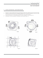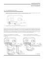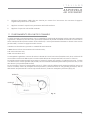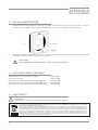
1
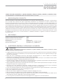
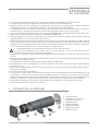
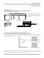
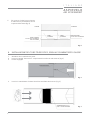
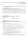
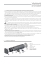
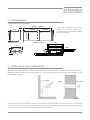
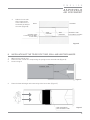
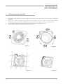
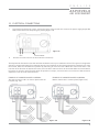
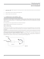
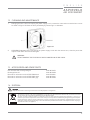
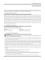
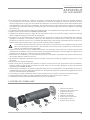
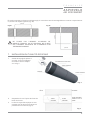
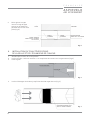
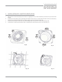
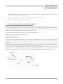
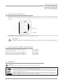
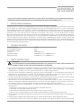
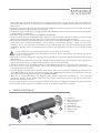
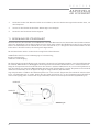
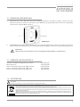
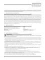
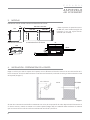
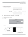
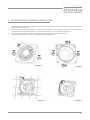
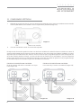
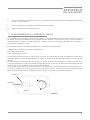
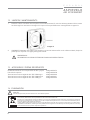
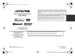
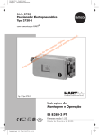
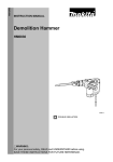
ASPIRVELO AIR ECOCOMFORT UNITÀ DI VENTILAZIONE MONOSTANZA CON RECUPERO DI CALORE MANUALE D’USO E DI INSTALLAZIONE PAG. 2 SINGLE ROOM HEAT RECOVERY UNIT USER INSTRUCTIONS PAG. 11 UNITÉ DE VENTILATION MONO-PIÈCE AVEC RÉCUPÉRATION DE CHALEUR MANUEL D'UTILISATION ET D'INSTALLATION PAG. 20 MONOSTANZA VENTILATOR MIT WÄRMERÜCKGEWINNUNG BENUTZER- UND INSTALLATIONSHANDBUCH PAG. 29 UNIDAD DE VENTILACION CONRECUPERACION DE CALOR MANUAL DE USO E INSTALACIÓN PAG. 38 I T A L I A N O A S P I R V E LO AIR ECOCOMFORT GRAZIE PER AVER ACQUISTATO IL NOSTRO PRODOTTO. PRIMA DI USARLO, LEGGERE IL MANUALE D’USO ACCURATAMENTE E CONSERVARLO BENE PER CONSULTARLO IN FUTURO. 1. DESCRIZIONE DEL PRODOTTO Unità di ventilazione e aspirazione decentralizzata con recupero di calore ad altissima efficienza. L’unità funziona con il principio del recupero del calore rigenerativo: attraverso uno scambiatore di calore ceramico posto all’interno del dispositivo che accumula il calore ceduto dal flusso d’aria entrante o uscente dalla stanza, e lo restituisce quando il flusso inverte il proprio verso. L’unità ventilante è comandata da un motore DC Brushless con funzionamento ad inversione di ciclo che permette il continuo scambio d’aria tra interno ed esterno. L’aria viene costantemente filtrata attraverso un filtro G3 installato sul frontale dell’apparecchio e facilmente estraibile al fine di consentirne la pulizia. L’unità è gestita da una elettronica di comando montata a parete che prevede tre modalità di funzionamento: automatico, immissione ed estrazione aria. Inoltre l'elettronica di comando permette di adeguare il funzionamento in base alla differenza fra la temperatura interna e la temperatura esterna. L'unità di comando può gestire fino a 4 unità ventilanti in modalità combinata e regolare la velocità di estrazione o immissione aria. 2. DATI TECNICI Tensione di alimentazione unità ventilante Grado di protezione unità di comando Grado di protezione unità ventilante Portata d'aria Livello di pressione sonora Potenza max assorbita 3. 12Vdc IP20 IPX4 (25÷50) m³/h 20dB @ 25 m³/h ; 25dB @ 50m³/h 2,0W @ 25 m³/h ; 2,8W @ 50 m³ AVVERTENZE GENERALI E ISTRUZIONI DI SICUREZZA AVVERTENZA! Leggere attentamente le istruzioni contenute in questo manuale, onde evitare il rischio di scosse elettriche, incendi e lesioni personali. • Leggere attentamente le avvertenze contenute nel presente libretto, in quanto forniscono importanti indicazioni riguardanti la sicurezza di installazione, d’uso e di manutenzione. Conservare con cura questo libretto per ogni ulteriore consultazione. • Dopo aver tolto l’imballaggio assicurarsi dell’integrità dell’apparecchio. In caso di dubbio non utilizzare l’apparecchio e rivolgersi a personale professionalmente qualificato. • Gli elementi dell’imballaggio (sacchetti in plastica, polistirolo espanso, chiodi, ecc.) non devono essere lasciati alla portata dei bambini, in quanto potenziali fonti di pericolo. • Prima di collegare l’apparecchio accertarsi che i dati di targa siano rispondenti a quelli della rete di distribuzione elettrica (la targa è situata sul lato superiore del portamotore). • Questo apparecchio dovrà essere destinato solo all’uso per il quale è stato espressamente concepito e cioè per aerazione dei locali con recupero di calore. • Ogni altro uso è da considerarsi improprio e quindi pericoloso. Il costruttore non può essere considerato responsabile per eventuali danni derivanti da usi impropri, erronei ed irragionevoli. • L’uso di un qualsiasi apparecchio elettrico comporta l’osservanza di alcune regole fondamentali. In particolare: • Non toccare l’apparecchio con mani o piedi bagnati o umidi. • Non usare l’apparecchio a piedi nudi. • Non lasciare esposto l’apparecchio ad agenti atmosferici (pioggia, sole, ecc.). • Non permettere che l’apparecchio sia usato da bambini o da incapaci senza sorveglianza. • Prima di effettuare qualsiasi operazione di pulizia o di manutenzione, disinserire l’apparecchio dalla rete di alimentazione elettrica, spegnendo l’interruttore dell’impianto. • In caso di guasto e/o cattivo funzionamento dell’apparecchio, spegnerlo e non manometterlo. 2 I T A L I A N O A S P I R V E LO AIR ECOCOMFORT • Per l’eventuale riparazione rivolgersi al rivenditore e richiedere l’utilizzazione di ricambi originali. • Il mancato rispetto di quanto sopra può compromettere la sicurezza dell’apparecchio. • Allorché si decida di non utilizzare più un apparecchio di questo tipo si raccomanda di renderlo inoperante scollegandolo dalla rete di alimentazione dopo aver staccato l’interruttore dell’impianto. • Si raccomanda, inoltre, di rendere innocue quelle parti dell’apparecchio suscettibili di costituire un pericolo, specialmente per i bambini che potrebbero servirsi dell’apparecchio fuori uso per i propri giochi. • L’esecuzione dell’impianto elettrico deve essere conforme alle Norme per gli impianti elettrici negli edifici civili. • Apparecchio conforme alle Direttive Europee: CE2006/95; CE2004/108. • Essendo l’apparecchio costruito a regola d’arte, con un uso corretto ed una regolare manutenzione, durata ed affidabilità elettrica e meccanica saranno più efficienti. • Questo apparecchio non è da intendersi adatto all’uso da parte di persone (incluso bambini) con ridotte capacità fisiche, sensoriali o mentali, o prive di esperienza e conoscenza, a meno che siano state supervisionate o istruite riguardo all’uso dell’apparecchio da una persona responsabile della loro sicurezza. I bambini dovrebbero essere supervisionati per assicurarsi che non giochino con l’apparecchio. • • • • • • • • • 4. • L’installazione deve essere effettuata secondo le istruzioni del costruttore. • Una errata installazione può causare danni a persone, animali o cose nei confronti dei quali il costruttore non può essere considerato responsabile. L’apparecchio è costruito secondo le norme del doppio isolamento (Classe II) e quindi non necessita del cavo di terra. Verificare che la portata elettrica dell’impianto e delle prese di corrente siano adeguate alla potenza massima dell’apparecchio indicata in targa. In caso di dubbio rivolgersi ad una persona professionalmente qualificata. All’installazione occorre prevedere un interruttore onnipolare con distanza di apertura dei contatti uguale o superiore a 3 mm. Non lasciare l’apparecchio inutilmente inserito. Spegnere l’interruttore generale dell’apparecchio quando lo stesso non è utilizzato. Non ostruire la griglia di aspirazione. A norma delle vigenti Leggi antinfortunistiche assicurarsi che, ad installazione avvenuta dell’aspiratore, non sia possibile, in nessun caso, accedere dal lato mandata alle parti in movimento. Se nel locale da ventilare è installato un apparecchio a gas (o altri combustibili) è indispensabile verificare che vi sia un adeguato rientro dell’aria, per garantire la perfetta combustione dello stesso ed il corretto funzionamento del ventilatore. Non installare l’aspiratore nello stesso condotto dove sono convogliati i fumi di un apparecchio a gas. L’installazione può essere eseguita solo a parete. CONTENUTO DELLA CONFEZIONE 5 2 3 4 1. Unità ventilante 2. Scambiatore di calore con maniglia di estrazione 3. Tubo telescopico 4. Unità di comando 5. Griglia dentro/fuori 6. Alimentatore 12Vcc 7. Foglio istruzioni 6 1 3 I T A L I A N O A S P I R V E LO AIR ECOCOMFORT 5. DIMENSIONI UNITÀ VENTILANTE CON RECUPERATORE 20 max 530 - min 240* 180 * per spessori di parete inferiori a 280mm tagliare il tubo a seconda della propria necessità ed utilizzare una griglia esterna standard (non in dotazione). 47 max 280 180 max Ø 160 max 280 UNITÀ DI COMANDO ALIMENTATORE 90 82.5 77 140 31 40 15.5 85 19 150±10 T case 150±10 6. INSTALLAZIONE - PREPARAZIONE DELLA PARETE Realizzare, per tutto lo spessore della parete, un foro di diametro minimo 162 mm con inclinazione di 1° verso l’ambiente esterno. Il foro deve essere posizionato ad una altezza minima di 2,3mt dal pavimento e a 100 mm da eventuali pareti laterali (fig.1). min 100 mm 2 16 STANZA ESTERNO 2,3 mt 1° Ø Fig.1 Utilizzando nello stesso ambiente due sistemi di ventilazione monostanza con recupero di calore serie Aspirvelo Air Ecocomfort, nel caso di montaggio sulla stessa parete (fig. 2a), l’installazione deve essere effettuata in modo tale che il centro dei fori di carotaggio siano ad una distanza minima di 1,2 metri. 4 I T A L I A N O A S P I R V E LO AIR ECOCOMFORT Nel caso invece di montaggio su due pareti ad angolo, i centri dei fori di carotaggio devono trovarsi rispettivamente ad 1,2 metri dalla parete opposta (fig. 2b). 1,2 mt Fig.2b 1,2 mt Fig.2a NON POSIZIONARE IL DISPOSITIVO SOPRA MOBILI DELICATI O QUADRI. NON POSIZIONARE IL DISPOSITIVO SOPRA O VICINO A TERMOSTATI AMBIENTE. 1,2 mt 7. INSTALLAZIONE DEL TUBO TELESCOPICO 1. Utilizzando l’apposita maniglia, estrarre lo scambiatore di calore come indicato dalla fig.3. SCAMBIATORE DI CALORE TUBO INTERNO MANIGLIA TUBO ESTERNO Fig. 3 STANZA 2. 3. Cospargere il foro appena realizzato con malta cementizia. Inserire il tubo telescopico assicurandosi che il tubo di diametro maggiore sia a filo con la parete esterna (fig.4). ESTERNO TUBO INTERNO TUBO ESTERNO TUBO ESTERNO A FILO CON LA PARETE Fig. 4 5 I T A L I A N O A S P I R V E LO AIR ECOCOMFORT 4. Far scorrere il tubo interno rispetto al tubo esterno portandolo a filo con la parete della stanza (fig. 5) STANZA TUBO INTERNO A FILO CON LA PARETE DELLA STANZA ESTERNO TUBO INTERNO TUBO ESTERNO TUBO ESTERNO A FILO CON LA PARETE Fig. 5 8. INSTALLAZIONE DEL TUBO TELESCOPICO, GRIGLIA E SCAMBIATORE DI CALORE 1. 2. 3. Attendere che la malta faccia presa. Inserire la griglia “dentro fuori” comprimendo le molle sul tubo esterno (fig. 6) Fissare la griglia TUBO ESTERNO MOLLE Fig. 6 4. Inserire lo scambiatore di calore fino all’estremità del tubo interno. (fig. 7) SCAMBIATORE A FILO CON IL TUBO INTERNO 6 Fig. 7 I T A L I A N O A S P I R V E LO AIR ECOCOMFORT 9. INSTALLAZIONE DELL'UNITÀ VENTILANTE 1. 2. Sganciare il coperchio (2) dal portamotore premendo sui fori laterali (1) mediante un piccolo cacciavite (fig. 8). Fratturare l’imposta prevista per il passaggio collegamenti (3), nel caso di collegamenti esterni non sotto traccia fratturare le zone previste (4) sia sul portamotore che sul coperchio (fig. 9). Fissare il portamotore in corrispondenza del foro di scarico mediante viti e tasselli (fig. 10). Posizionare il cavo di alimentazione nell’apposita sede antitrazione (fig. 11). 3. 4. 3 2 4 1 4 1 Fig. 8 Fig. 10 4 Fig. 9 Fig. 11 7 I T A L I A N O A S P I R V E LO AIR ECOCOMFORT 10. COLLEGAMENTI ELETTRICI 1. Svitando l’apposita vite di fissaggio, smontare il coperchio dell’unità di comando. Collegare i cavi di uscita dell’alimentatore (DC OUT) all’unità di comando rispettando le polarità (fig.12). Fig. 12 + 12Vdc 2. VITE DI FISSAGGIO Collegare l’unità di comando alla morsettiera dell’aspiratore/i. L’Aspirvelo Air Ecocomfort può funzionare con due unità ventilanti fino ad un massimo di quattro. Il sistema è stato pensato per funzionare in maniera alternata. Se per esempio in un ambiente sono installate due unità, il primo dispositivo opera immettendo aria dall’esterno mentre il secondo dispositivo opera estraendo aria dalla stanza. Quando dopo un certo tempo si ha l’inversione del senso di rotazione delle ventole, il primo dispositivo estrae l’aria verso l’esterno mentre il secondo dispositivo immette l’aria nella stanza. L’alternanza del funzionamento in coppia, assicura che la somma della portata d’aria immessa sia pari alla somma della portata estratta. ESEMPIO DI COLLEGAMENTO CON 4 MOTORI: La coppia di motori A-B è in contro fase con la coppia C-D (fig. 13a) ESEMPIO DI COLLEGAMENTO CON 2 MOTORI: Il motore A ed il motore C sono in contro fase (fig.13b) Fig. 13a 8 Fig. 13b I T A L I A N O A S P I R V E LO AIR ECOCOMFORT 3. Collegare l’alimentatore 12Vdc alla rete elettrica per mezzo di un interruttore che consenta di spegnere l’apparecchio quando non è utilizzato. 4. Applicare a scatto il coperchio sul portamotore dell’unità ventilante. 5. Applicare il coperchio sull’unità di comando. 11. FUNZIONAMENTO DELL’UNITÀ DI COMANDO L’unità di comando, montata sia a parete che su scatola 503, è costituita da due deviatori a slitta e da una manopola di regolazione. Il deviatore a slitta di sinistra, permette di modificare la portata scambiata fra la stanza e l’esterno da un valore massimo di 50 m³/h ad un valore minimo di 25 m³/h. Inoltre posizionando il deviatore a slitta di sinistra sulla posizione OFF, si ottiene lo spegnimento del sistema. Il deviatore a slitta di destra, prevede tre modalità di funzionamento: • Auto: alterna il flusso fra estrazione ed immissione aria; • In: solo immissione aria; • Out: solo estrazione aria. La manopola di regolazione consente di variare la durata del ciclo di immissione/estrazione aria, da un minimo di 35 secondi ad un massimo di 200 secondi in funzione della differenza di temperatura ΔT fra l’esterno e l’interno. Se la differenza di temperatura ΔT fra la stanza e l’esterno è elevata, per garantire il rendimento termico, il tempo ciclo deve essere il minore possibile (35 secondi). Se invece la differenza di temperatura ΔT è prossima a zero, il ciclo deve durare il più possibile (200 secondi). Se per esempio in inverno la temperatura esterna è –15°C e quindi la differenza di temperatura ΔT fra interno ed esterno è elevata, ruotare la manopola fino alla posizione (1). Contrariamente in una giornata primaverile, dove la differenza di temperatura ΔT è minima o prossima allo zero, ruotare la manopola in posizione (2) (fig.14). Q=50m³/h 1 Q=25m³/h 2 Fig. 14 9 I T A L I A N O A S P I R V E LO AIR ECOCOMFORT 12. PULIZIA E MANUTENZIONE 1. Sostituzione del filtro: dopo aver interrotto il circuito di alimentazione, smontare il coperchio e svitare le quattro viti come indicato in fig. 15. Pulire periodicamente il filtro immergendolo in acqua fredda. Fig. 15 2. PULIZIA PLASTICHE: Dopo aver interrotto il circuito di alimentazione, usando la massima attenzione, pulire con acqua e detersivo neutro le parti che lo richiedono. ATTENZIONE: NON IMMERGERE IN ACQUA O ALTRI LIQUIDI LE PARTI ELETTRICHE. 13. ACCESSORI E PARTI DI RICAMBIO Unità ventilante con recuperatore e griglia Filtro G3 di ricambio Terminale esterno di immissione aria TPE-150N nero Terminale esterno di immissione aria TPE-150B bianco Terminale esterno di immissione aria TPE-150G grigio Cod. AP19979 Cod. AP19978 Cod. AP19900 Cod. AP19901 Cod. AP19902 14. SMALTIMENTO ATTENZIONE: Informazione importante per lo smaltimento ecosostenibile dell’apparecchio. Il simbolo del cassonetto barrato riportato sull’apparecchiatura indica che il prodotto alla fine della propria vita utile deve essere raccolto separatamente dagli altri rifiuti. L’utente dovrà, pertanto, conferire l’apparecchiatura giunta a fine vita agli idonei centri di raccolta differenziata dei rifiuti elettronici ed elettrotecnici, oppure riconsegnarla al rivenditore al momento dell’acquisto di una nuova apparecchiatura di tipo equivalente, in ragione di uno a uno. L’adeguata raccolta differenziata per l’avvio successivo dell’apparecchiatura dismessa al riciclaggio, al trattamento e allo smaltimento ambientalmente compatibile contribuisce ad evitare possibili effetti negativi sull’ambiente e sulla salute e favorisce il riciclo dei materiali di cui è composta l’apparecchiatura. Lo smaltimento abusivo del prodotto da parte dell’utente comporta l’applicazione delle sanzioni amministrative di cui al D.Lgs. n. 22/1997” (articolo 50 e seguenti del D.Lgs. n. 22/1997). 10 E N G L I S H A S P I R V E LO AIR ECOCOMFORT THANK YOU FOR PURCHASING OUR PRODUCT. BEFORE USE, READ THE USER MANUAL CAREFULLY AND KEEP IT SAFE FOR CONSULTATION IN THE FUTURE. 1. PRODUCT DESCRIPTION Decentralized ventilation and suction unit with high efficiency heat recovery. The unit works with the principle of regenerative heat recovery: by means of a ceramic heat exchanger placed inside the device that collects the heat given off by the air flow entering or leaving the room, and returns it when the flow reverses its direction. The fan unit is controlled by a DC Brushless motor with reverse cycle operation that allows the continuous exchange of air between inside and outside. The air is continually filtered through a G3 filter installed on the front of the appliance and easily removable for cleaning purposes. The unit is managed by a wall mounted electronic control unit that features three operation modes: automatic, collection and extraction of air. Furthermore, the electronic control allows for the adjustment of operation according to the difference between interior and exterior temperature. The control unit can manage up to 4 ventilation units in combined mode and regulate the speed of air extraction or collection. 2. TECHNICAL DATA Fan unit power supply Control unit degree of protection Fan unit degree of protection Airflow Sound pressure level Maximum power 3. 12Vdc IP20 IPX4 (25 ÷ 50) m³ / h 20dB @ 25 m³ / h ; 25dB @ 50m³ / h 2,0W @ 25 m³ / h ; 2,8W @ 50 m³ SAFETY INSTRUCTIONS WARNING! READ THIS INSTRUCTION CAREFULLY IN ORDER TO AVOID THE RISK OF ELECTRIC SHOCK, FIRE OR INJURY. • Read carefully the instructions in this booklet as they give important information on the correct installation, use and maintenance of the appliance. • Keep this booklet in a safe place so that it will be available for future reference. • After unpacking check the integrity of the set. In case of doubt do not use the set and ask for qualified person’s intervention. • All the packaging (plastic bags, polystyrene foam, nails, etc) must be kept out of the reach of children. • Before connecting the appliance to the mains supply ensure that the rating label specifications correspond to your electrical supply. (The rating label is to be found on the top part of the motor holder). • This appliance must only be used for the purpose for which it was designed i.e. ventilation of rooms. • All other uses must be considered to be potentially dangerous. The Manufacturer cannot be held responsible for any damage caused by improper, incorrect or unreasonable use. • The safe use of any electrical appliance involves the observing of certain basic rules, in particular: • Do not touch the appliance with wet or moist hands or feet. • Do not use the appliance with bare feet. • Do not pull the plug from the power socket by the mains lead of the appliance itself. • Do not leave the appliance where it is exposed to adverse elements such as rain, salt etc. • Do not let young children, aged or infirm people use the device without supervision. • Before beginning any cleaning or maintenance operations disconnect the appliance from the electrical supply by taking out the plug or switching off the appliance insolation switch. • In case of a fault and/or malfunction of the appliance, switch it off but do not attempt to rectify. • Seek advice from a suitably qualified person. 11 E N G L I S H A S P I R V E LO AIR ECOCOMFORT • • • • • • • • • • • • • • • 4. • If repair is necessary contact the Manufacturer and ask for only original spare parts. • If the above action is not carried out, the safety of the appliance could be jeopardized. Should it be decided not to use this appliance any longer, it should be removed from the electrical supply and rendered inoperative, then disposed of in the normal manner. It is also recommended to make harmless those parts of the appliance which could be harmful, especially to children who might play with the disused appliance. The installation must conform to the requirements of the latest issue of the I.E.E. wiring regulations. This appliance has been constructed to comply with the requirements of the following European Directives CE2006/95; CE2004/108. The set is workmanlike manufactured. A correct use and a regular maintenance guarantee life and reliability of all electrical and mechanical parts. This appliance is not intended for use by persons (including children) with reduced physical, sensory or lack of experience and knowledge unless they have been given supervision or instruction concerning use of the appliance by a person responsible for their safety. Children should bensure that they do not play with the appliance. • Installation must be carried out as detailed in these instructions. The user is warned that incorrect installation could cause harm to persons or animals or damage to property. The Manufacturer cannot be held responsible in such cases. The apparatus is double insulated (Class II) and does not require earthing. Check that the current carrying capacity of the mains wiring and socket are adequate for the maximum rating of the device shown on the rating label. In case of doubt consult a suitably qualified person. When installing, it is necessary to use a double pole switch with a contact separation of 3 mm or more. Do not leave the appliance plugged if unnecessary. Switch off the main switch of the appliance when the appliance is not in use. Do not obstruct the air inlet or outlet grilles. In conformity with prevention and safety laws in force, when installation of exhaust fan is completed, make sure that it is not at all possible to reach the motion parts from the inlet side. On the contrary it is necessary to mount the special protection shutter (cod. AP0885, AP0893). If there is already a combustion fuel appliance in the room, it is essential to ensure that the air supply to the room is adequate for the correct functionning of both the combustion appliance and the fan. Do not install the fan in the same duct where gas appliance fume is conveyed. The appliance must discharge into a single exhaust pipe or directly outside the building. The system can be either wall-mounted or ceiling-mounted. PACKAGE CONTENTS 5 2 1 12 3 4 6 1. Fan unit 2. Heat exchanger with extraction handle 3. Telescopic tube 4. Control unit 5. Grid inside/outside 6. Power supply 12Vcc 7. Instruction sheet E N G L I S H A S P I R V E LO AIR ECOCOMFORT 5. MEASUREMENTS FAN UNIT WITH HEAT RECOVERY 20 max 530 - min 240* 180 max 280 * For wall thickness of less than 280mm, cut the pipe according to necessity and use a standard outdoor grill (not supplied). 47 180 max Ø 160 max 280 CONTROL UNIT POWER SUPPLY 90 82.5 77 140 31 40 15.5 85 19 150±10 T case 150±10 6. INSTALLATION - WALL PREPARATION Make a hole, through the whole thickness of the wall, of a minimum diameter of 162 mm, with an inclination of 1° towards the exterior. The hole should be located at a minimum height of 2.3m from the ground and 100 mm from the wall side (Figure 1). min 100mm 2 ROOM EXTERNAL 2.3m 1° 6 Ø1 Figure 1 Using two monostanza ventilation systems with Aspirvelo Air Ecocomfort heat recovery series in the same environment, when mounted on the same wall (figure 2a), the installation must be carried out in such a way that the centers of the drill holes are at a minimum distance of 1.2 meters. 13 E N G L I S H A S P I R V E LO AIR ECOCOMFORT If instead mounted on two corner walls, the centers of the drill holes must be respectively located at 1.2 meters from the opposite wall (fig. 2b). 1.2m Figure 2b 1.2m Figure 2a DO NOT PLACE THE DEVICE ON DELICATE FURNITURE OR PAINTINGS. DO NOT PLACE THE DEVICE ON OR NEAR THERMOSTATS. 1.2m 7. INSTALLATION OF THE TELESCOPIC TUBE 1. Using the handle, pull out the heat exchanger as shown in Figure 3. HEAT EXCHANGER INTERNAL TUBE HANDLE EXTERNAL TUBE Figure 3 ROOM 2. 3. Dust the newly drilled hole with cement mortar. Insert the telescopic tube making sure that the larger diameter tube is flush with the outer wall (Figure 4). EXTERNAL TUBE INTERNAL TUBE EXTERNAL EXTERNAL TUBE FLUSH WITH THE WALL Figure 4 14 E N G L I S H A S P I R V E LO AIR ECOCOMFORT 4. Slide the inner tube with respect to the outer tube until it is flush with the wall of the room (Figure 5) ROOM INTERNAL TUBE FLUSH WITH THE WALL OF THE ROOM EXTERNAL TUBE INTERNAL TUBE EXTERNAL EXTERNAL TUBE FLUSH WITH THE WALL Figure 5 8. INSTALLATION OF THE TELESCOPIC TUBE, GRILL AND HEAT EXCHANGER 1. 2. 3. Wait until the mortar sets. Place the rack "inside out" compressing the springs on the external tube (Figure 6) Secure the grill EXTERNAL TUBE SPRINGS Figure 6 4. Place the heat exchanger at the extremity of the inner tube. (Figure 7) WIRE EXCHANGER WITH INTERNAL TUBE Figure 7 15 E N G L I S H A S P I R V E LO AIR ECOCOMFORT 9. INSTALLATION OF FAN UNIT 1. Unhook the cover (2) from the motor support by pressing on the side holes (1) using a small screwdriver (Figure 8). Fracture the shutter provided for the transfer of connections (3), in the case of non-concealed external connections, fracture the zones provided for (4) both on the motor support and on the cover (Figure 9). Fix the motor support at the evacuation hole with screws and raw plugs (Figure 10). Place the power cable in the appropriate place (Figure 11). 2. 3. 4. 3 2 4 1 4 1 Figure 8 Figure 10 16 4 Figure 9 Figure 11 E N G L I S H A S P I R V E LO AIR ECOCOMFORT 10. ELECTRICAL CONNECTIONS 1. Unscrewing the fastening screws, remove the cover of the control unit. Connect the power supply output (DC OUT) to the control unit respecting the polarity (Figure 12). Figure 12 + 12Vdc 2. FIXING SCREWS Connect the control unit to the terminal of the vacuum/s. The Aspirvelo Air Ecocomfort can work with two ventilation units up to a maximum of four. The system is designed to operate in an alternating way. If for example two units are installed, the first device operates by introducing air from the outside, while the second device operates by extracting air from the room. When after some time there is the inversion of the direction of rotation of the fans, the first device extracts the air to the outside while the second device brings the air into the room. The alternation of operation in torque, ensures that the sum of the air flow emitted is equal to the sum of the air flow extracted. EXAMPLE OF CONNECTION WITH 4 MOTORS: The pair of motors A-B is in counter phase with the C-D pair (Fig. 13a) EXAMPLE OF CONNECTION WITH 2 MOTORS: Motors A and C are in counter phase (Figure 13b) Figure 13a Figure 13b 17 E N G L I S H A S P I R V E LO AIR ECOCOMFORT 3. Connect the 12Vdc power supply to the mains by means of a switch which allows the device to be switched off when not in use. 4. Snap closed the cover on the fan motor support unit. 5. Place the cover on the control unit. 11. OPERATION OF THE CONTROL UNIT The control unit, mounted either on a wall or box 503, is made up of two sliding switches and one control knob. The sliding switch on the left, allows for the modification of the flow between the room and the outside from a maximum of 50 m³ / h to a minimum of 25 m³ / h. Besides placing the sliding switch on the left in the OFF position, you get a system shutdown. The sliding switch on the right provides for three modes of operation: • Auto: changes the flow from extraction to collection of air; • In: air collection only; • Out: air extraction only. The adjustment knob allows for the variation of the duration of cycles of air collection/extraction, from a minimum of 35 seconds to a maximum of 200 seconds depending on the temperature ΔT difference between the exterior and the interior. If the difference in temperature ΔT between the room and the exterior is raised, in order to guarantee the thermal output, the time cycle must be the shortest possible (35 seconds). If instead the difference in temperature ΔT is close to zero, the cycle must last as long as possible (200 seconds). If for example in winter the exterior temperature is -15°C and thus the difference in temperature ΔT between the interior and the exterior is raised, turn the knob to position (1). Unlike a day in spring, where the difference in temperature ΔT is minimal or close to zero, turn the knob to position (2) (Figure 14). Q=50m³/h 1 Q=25m³/h 2 Figure 14 18 E N G L I S H A S P I R V E LO AIR ECOCOMFORT 12. CLEANING AND MAINTENANCE 1. Changing the filter: after interrupting the power supply circuit, remove the cover and unscrew the four screws as shown in Figure 15. Clean the filter periodically by immersing it in cold water. Figure 15 2. CLEANING PLASTICS: After interrupting the power supply circuit with the utmost care, clean the parts that require it with water and neutral detergent. WARNING: DO NOT IMMERSE THE ELECTRICAL PARTS IN WATER OR OTHER LIQUID. 13. ACCESSORIES AND SPARE PARTS Fan unit with heat recovery and grill Exchange filter G3 External air collection terminal TPE-150N black External air collection terminal TPE-150B white External air collection terminal TPE-150G grey Code AP19979 Code AP19978 Cod. AP19900 Code AP19901 Code AP19902 14. DISPOSAL WARNING WARNING: Important information concerning the environment friendly disposal of the appliance This product conforms to EU Directive 2002/96/EC. The symbol of the barred waste bin indicates that, at the end of its useful life, the product has to be collected separately from the domestic waste. The user will have to take the product to a collection centre for waste electrical and electronic equipment, or return it to a retailer on purchase of a replacement. Failure to do so may incur the penalties established by laws governing waste disposal. Proper differential collection and the subsequent recycling, processing and environmentally compatible disposal of waste equipments avoids unnecessary damage to the environment and possible related health risk and promotes also recycling of the materials used in the appliance. 19 F R A N Ç A I S E A S P I R V E LO AIR ECOCOMFORT MERCI D'AVOIR ACHETÉ NOTRE PRODUIT. AVANT TOUTE UTILISATION, VEUILLEZ LIRE ATTENTIVEMENT CE MANUEL, ET CONSERVEZ-LE POUR POUVOIR VOUS Y RÉFÉRER ULTÉRIEUREMENT. 1. DESCRIPTION DU PRODUIT Unité de ventilation et d'aspiration décentralisée avec récupération de chaleur à très haute efficacité. L'unité fonctionne selon un principe de récupération de chaleur régénérative : à travers un échangeur de chaleur en céramique situé à l'intérieur du dispositif qui accumule la chaleur du flux d'air entrant ou sortant de la pièce, et le restitue quand le flux s'inverse. L'unité de ventilation est contrôlée par un moteur à courant continu Brushless avec fonctionnement à inversion de cycle qui permet un échange d'air continu entre l'intérieur et l'extérieur. L'air est constamment filtré à travers un filtre G3 installé sur la face avant de l'appareil et facilement extractible afin de pouvoir le nettoyer. L'unité est gérée par un circuit électronique de commande monté sur le mur, qui offre trois modes de fonctionnement : automatique, entrée et sortie d'air. De plus le système électronique de commande permet de régler le fonctionnement en fonction de la température interne et de la température externe. L'unité de commande peut gérer le fonctionnement de 4 unités de ventilation différentes en mode combiné et de régler la vitesse de sortie ou d'entrée d'air. 2. DONNÉES TECHNIQUES Tension d'alimentation unité de ventilation Classe de protection de l'unité de commande Classe de protection de l'unité de ventilation Débit d'air Niveau de pression sonore Puissance max absorbée 3. 12 V cc IP20 IPX4 (25÷50) m³/h 20 dB @ 25 m³/h ; 25dB @ 50m³/h 2,0 W @ 25 m³/h ; 2,8 W @ 50 m³ INSTRUCTIONS GENERALES ATTENTION: LISEZ ATTENTIVEMENT LES INSTRUCTIONS DE CE MANUEL POUR ÉVITER LES RISQUES DE CHOC ÉLECTRIQUE, UN INCENDIE OU DES BLESSURES. • Lire attentivement les instructions contenues dans ce livret, car elles fournissent d’importantes indications sur la sécurité pour l’installation, I’utilisation et la maintenance. Conserver soigneusement ce livret afin de pouvoir le consulter ultérieurement en cas de besoin. • Aprés avoir enlevé l’emballage, s’assurer que l’appareil soit intact. En cas de doutes, ne pas se servir de l’appareil et s’adresser au personnel qualifié. Les éléments de l’emballage (sachets en plastique, polystyrène expansé, clous, etc.. ) ne doivent pas être laissés à la portée des enfants car peuvent représenter des sources potentielles de danger. • Avant de relier l’appareil, s’assurer que le s données indiquées sur la plaquette correspondent à celles du réseau de distribution electrique. (La plaquette est située sur la partie supérieure du porte-moteur). • Cet appareil ne doit être destiné qu’à l’usage pour lequel il a été expressément conçu, c’est-à-dire pour l’aération des locaux. Tout autre usage doit être considéré impropre et par consequent dangereux. Le constructeur ne peut pas être tenu pour responsable en cas d’éventuels dommages causés par une utilisation impropre, erronée et irraisonnée. • L’utilisation d’un appareil électrique quelconque implique l’observation de certaines règles fondamentales. En particulier: • Ne pas toucher l’appareil avec les mains ou les pieds mouillés ou humides. • Ne pas utiliser l’appareil avec les pieds nus. • Ne pas exposer l’appareil aux agents atmosphériques (pluie, soleil, etc...). • Ne pas laisser sans surveillance les enfants ou les personnes incapables d’utiliser l’appareil tout seuls. • Avant d’effectuer toute opération de nettoyage ou de maintenance, déconnecter l’appareil du réseau d’alimentation électrique et éteindre l’interrupteur de l’installation. • En cas de panne et/ou de mauvais fonctionnement de l’appareil, éteindre celui-ci et ne le toucher plus. 20 F R A N Ç A I S E A S P I R V E LO AIR ECOCOMFORT • Pour d’éventuelles réparations, s’adresser au vendeur, et demander qu’on utilise les pièces de rechange originaux. Le non-respect de ces normes pourrait compromettre la sécurité de l’appareil. Lorsqu’on décide de ne plus utiliser un appareil de ce type, on recommande de le desactiver en le déconnectant du réseau d’alimentation après avoir débranché l’interrupteur de l’installation. On conseille aussi de rendre inoffensives les parties de l’appareil susceptibles de représenter un danger, spécialement pour les enfants qui pourraient utiliser l’appareil hors d’usage pour leurs jeux. • L’installation électrique doit être conforme aux Normes pour les installations électriques dans les édifices civils. • Appareil conforme aux Directives CE2006/95; CE2004/108. • L’appareil est fabriqué suivant les règles de l’art. Un emploi correct et un entretien régulier assurent une longue durée et fiabilité des parties électriques et mécaniques. • Cet appareil n’est pas adapté pour être utilisé par des personnes (y compris des enfants) ayant des capacités physiques, sensorielles ou mentales réduites ou sans expérience et connaissance, à moins qu’elles ne soient surveillées ou aient été instruites sur l’utilisation de l’appareil par une personne responsable de leur sécurité. Les enfants devront être surveillés pour s’assurer qu’ils ne jouent pas avec l’appareil. • • • • • • • • • • L’installation doit être effectuée selon les instructions du constructeur. Une installation incorrecte peut causer des dommages aux personnes, aux animaux et aux choses, envers lesquelles le constructeur ne peut être considéré comme responsable. L’appareil est construit en classe II (double isolement) et il ne nécessite pas de mise à terre. Vérifier que la portée électrique de l’installation et de la prise de courant corresponde à la puissance max de l’appareil, indiquée sur la plaquette. En cas de doutes, s’adresser à une personne qualifiée. Au moment de l’installation, il est nécessaire de prévoir un interrupteur omnipolaire avec distance d’ouvertures des contacts égale ou supérieure à 3 mm. Ne pas laisser l’appareil inutilement branché. Eteindre I’interrupteur général de l’appareil lorsque celui-ci n’est pas utilisé. Ne pas obstruer la grille d’aspiration. Selon les lois pour la prévention des accidents en vigueur, il faut s’assurer que, après avoir terminé l’installation, la partie mobile ne résulte pas accessible tout à fait. Dans les cas contraire, appliquer la grille de protection appropriée (cod. AP0885, AP0893). Si dans la pièce à ventiler il est installé un appareil à gaz (ou autre combustible) il est indispensable de s’assurer préalablement qu’il y ait une adéquate rentrée de l’air pour garantir la parfaite combustion de l’appareil existant et le correct fonctionnement du ventilateur. On ne doit pas, installer l’aspirateur dans le même conduit où sont renvoyès les fumées d’un appareil à gaz. L’appareil doit evacuer dans un tuyau d’exhalation individuel ou bien directement à l’extérieur. L’installation peut être effectuée indifféremment au mur ou au plafond. 4. CONTENU DE L'EMBALLAGE 5 2 3 4 1. Unité de ventilation 2. Échangeur de chaleur avec poignée d'extraction 3. Tuyau télescopique 4. Unité de commande 5. Grille intérieur/extérieur 6. Alimentateur 12 V cc 7. Feuillet d'instructions 6 1 21 F R A N Ç A I S E A S P I R V E LO AIR ECOCOMFORT 5. DIMENSIONS UNITÉ DE VENTILATION AVEC RÉCUPÉRATEUR 20 max 530 - min 240* 180 * pour des murs d'une épaisseur inférieure à 280 mm, taillez le tuyau si nécessaire et utilisez une grille externe standard (non fourni). 47 max 280 180 max Ø 160 max 280 UNITÉ DE COMMANDE ALIMENTATEUR 90 82.5 77 140 31 40 15.5 85 19 150±10 T case 150±10 6. INSTALLATION - PRÉPARATION DU MUR Réalisez, sur toute l'épaisseur du mur, un trou d'un diamètre minimum de 162 mm avec une inclinaison de 1° vers l'extérieur. Le trou doit être positionné à une hauteur minimale de 2,3 m du sol et à 100 mm d'éventuels murs latéraux (fig. 1). min 100 mm 2 16 PIÈCE EXTERNE 2,3 mt 1° Ø Fig.1 Si vous souhaitez utiliser deux systèmes de ventilation mono-pièce avec récupération de chaleur série Aspirvelo Air Ecocomfort dans un même environnement, et en cas de montage sur le même mur (fig. 2a), l'installation doit être effectuée de façon à ce que le centre des trous de carottage se trouve à une distance d'au moins 1,2 mètre l'un de l'autre. 22 F R A N Ç A I S E A S P I R V E LO AIR ECOCOMFORT En cas de montage sur deux murs faisant angle, le centre des trous de carottage doivent se trouver respectivement à 1,2 mètre de la paroi opposée (fig. 2b). 1,2 mt Fig.2b 1,2 mt Fig.2a NE PLACEZ PAS L'APPAREIL AU-DESSUS DE MEUBLES FRAGILES OU DE TABLEAUX. NE PLACEZ PAS L'APPAREIL AU-DESSUS OU À PROXIMITÉ D'UN THERMOSTAT AMBIANT. 7. INSTALLATION DU TUYAU TÉLESCOPIQUE 1. A laide de la poignée prévue à cet effet, retirez l'échangeur de chaleur comme indiqué sur la fig. 3. 1,2 mt ÉCHANGEUR DE CHALEUR TUYAU INTERNE POIGNÉE TUYAU EXTERNE Fig. 3 PIÈCE 2. 3. Saupoudrez le trou à peine foré avec du laitier de ciment. Insérez le tuyau télescopique en vous assurant que le tube le plus large soit parallèle au mur externe (fig. 4). EXTERNE TUYAU INTERNE TUYAU EXTERNE TUYAU EXTERNE PARALLÈLE À LA PAROI Fig. 4 23 F R A N Ç A I S E A S P I R V E LO AIR ECOCOMFORT 4. Faites glisser le tuyau interne le long du tuyau externe en le plaçant en parallèle avec le mur de la pièce (fig. 5) PIÈCE TUYAU INTERNE PARALLÈLE À LA PAROI DE LA PIÈCE EXTERNE TUYAU INTERNE TUYAU EXTERNE TUYAU EXTERNE PARALLÈLE À LA PAROI Fig. 5 8. INSTALLATION DU TUYAU TÉLESCOPIQUE, DE LA GRILLE ET DE L'ÉCHANGEUR DE CHALEUR 1. 2. 3. Attendez que le laitier ait fini de prendre. Insérez la grille « intérieur extérieur » en comprimant les ressorts sur le tuyau externe (fig.6) Fixez la grille TUYAU EXTERNE RESSORTS Fig. 6 4. Insérez l'échangeur de chaleur jusqu'à l'extrémité du tuyau interne. (fig. 7) ÉCHANGEUR PARALLÈLE AVEC LE TUBE INTERNE 24 Fig. 7 F R A N Ç A I S E A S P I R V E LO AIR ECOCOMFORT 9. INSTALLATION DE L'UNITÉ DE VENTILATION 1. Décrochez le couvercle (2) du porte-moteur en appuyant sur les trous latéraux (1) à l'aide d'un petit tournevis (fig. 8). Fracturez le volet prévu pour le passage des branchements (3), en cas de branchements externes découverts, fracturez les zones prévues (4) sur le porte-moteur que sur le couvercle (fig. 9). Fixez le porte-moteur en face du trou de déchargement à l'aide de vis et de chevilles (fig. 10). Positionnez le câble d'alimentation dans l'emplacement antitraction prévu à cet effet (fig. 11). 2. 3. 4. 3 2 4 1 4 1 Fig. 8 Fig. 10 4 Fig. 9 Fig. 11 25 F R A N Ç A I S E A S P I R V E LO AIR ECOCOMFORT 10. BRANCHEMENTS ÉLECTRIQUES 1. Démontez le couvercle de l'unité de commande en dévissant . Branchez les câbles de sortie de l'alimentateur (DC OUT) à l'unité de commande en respectant les polarités (fig. 12). Fig. 12 + 12 V cc 2. VIS DE FIXATION Branchez l'unité de commande au bornier de l'aspirateur. L'Aspirvelo Air Ecocomfort peut fonctionner avec deux unités de ventilation, jusqu'à un maximum de quatre unités. Le système a été conçu pour fonctionner de façon alternée. Si, par exemple, deux unités sont installées dans une même pièce, le premier dispositif fonctionne et envoie de l'air provenant de l'extérieur, alors que le second dispositif, quant à lui, extrait l'air de la pièce. Quand, après un certain temps, le sens de rotation des hélices s'inverse, le premier appareil extrait l'air vers l'extérieur tandis que le deuxième appareil introduit l'air dans la pièce. Le fonctionnement alterné en couple permet d'assurer que la somme du débit d'air introduit est égale à la somme du débit extrait. EXEMPLE DE BRANCHEMENT AVEC 4 MOTEURS : Le couple de moteurs A-B est en contre-phase avec le couple C-D (fig. 13a) EXEMPLE DE BRANCHEMENT AVEC 2 MOTEURS : Le moteur A et le moteur C sont en contre-phase (fig. 13b) Fig. 13a 26 Fig. 13b F R A N Ç A I S E A S P I R V E LO AIR ECOCOMFORT 3. Branchez l'alimentateur 12 V cc au réseau électrique au moyen d'un interrupteur qui permet d'éteindre l'appareil quand celui-ci n'est pas utilisé. 4. Replacez le couvercle en le clipsant sur le porte-moteur de l'unité de ventilation. 5. Replacez le couvercle sur l'unité de commande. 11. FONCTIONNEMENT DE L'UNITÉ DE COMMANDE L’unité de commande, montée sur la paroi ou sur la boîte 503, est constituée de deux déviateurs à coulisse et d'une poignée de réglage. Le déviateur à coulisse de gauche permet de modifier le débit échangé entre la pièce et l'extérieur entre d'une valeur maximale de 50 m³/h à une valeur minimale de 25 m³/h. De plus, le système peut être arrêté en basculant le déviateur à coulisse de droite en position OFF. Le déviateur à coulisse de droite compte trois modes de fonctionnement : • Auto : alterne le flux entre entrée et sortie d'air ; • In : entrée d'air uniquement ; • Out: sortie d'air uniquement. La poignée de réglage permet de modifier la durée du cycle d'entrée/sortie d'air, à partir d'un minimum de 35 secondes et jusqu'à un maximum de 200 secondes, selon la différence de température ΔT entre l'extérieur et l'intérieur. Si la différence de température ΔT entre la pièce et l'extérieur est élevée, le temps de cycle doit être le plus faible possible (35 secondes) afin de garantir un bon rendement thermique. Si au contraire la différence de température ΔT est proche de zéro, le cycle doit durer le plus longtemps possible (200 secondes). Si, par exemple en hiver, la température externe est de -15°C, et donc la différence de température ΔT entre l'extérieur et l'intérieur est élevée, tournez la poignée en position (1). Au contraire, par une journée de printemps, ou la différence de température ΔT est minimale ou proche de zéro, tournez la poignée en position (2) (fig. 14). Q = 50 m³/h 1 Q = 25 m³/h 2 Fig. 14 27 F R A N Ç A I S E A S P I R V E LO AIR ECOCOMFORT 12. NETTOYAGE ET ENTRETIEN 1. Remplacement du filtre : après avoir interrompu le circuit d'alimentation, démontez le couvercle et dévissez les quatre vis comme indiqué sur la figure 15. Nettoyez régulièrement le filtre en le plongeant dans de l'eau froide. Fig. 15 2. NETTOYAGE DES PLASTIQUES : Après avoir interrompu le circuit d'alimentation, nettoyez avec le plus grand soin les pièces qui le nécessitent avec de l'eau et un savon neutre. ATTENTION : NE JAMAIS PLONGER LES PARTIES ÉLECTRIQUES DANS DE L'EAU OU DANS D'AUTRES LIQUIDES. 13. ACCESSOIRES ET PIÈCES DE RECHANGE Unité de ventilation avec récupérateur et grille Filtre G3 de rechange Embout externe d'entrée d'air TPE-150N noir Embout externe d'entrée d'air TPE-150B blanc Embout externe d'entrée d'air TPE-150G gris Réf. AP19979 Réf. AP19978 Réf. AP19900 Réf. AP19901 Réf. AP19902 14. DISPOSAL ATTENTION: Informations importantes pour l'élimination respectueuse de l'environnement de l'unité Ce produit conforme à la Directive européenne 2002/96/CE. Le symbole de la poubelle barré indique que, à la fin de la durée de vie utile, le produit doit être collectés séparément des déchets domestiques. L'utilisateur devra prendre le produit à un centre de collecte des déchets d'équipements électriques et électroniques, ou le retourner à un détaillant à l'achat d'un remplaçant. Ne pas le faire mai courbes et les pénalités forfaitaires établis par les lois régissant l'élimination des déchets. L'élimination appropriée de collecte différencié et le recyclage ultérieur, le traitement et compatible avec l'environnement des déchets d'équipements inutiles évite les dommages à l'environnement et risque pour la santé liés possible et également la promotion du recyclage des matériaux utilisés dans l'appareil. 28 D E U T S C H A S P I R V E LO AIR ECOCOMFORT DANKE FÜR DEN KAUF UNSERES PRODUKTES. LESEN SIE BITTE VOR GEBRAUCH DIESES BENUTZERHANDBUCH SORGFÄLTIG DURCH UND BEWAHREN SIE ES FÜR ZUKÜNFTIGE NACHSCHLAGEZWECKE AUF. 1. PRODUKTBESCHREIBUNG Dezentralisiertes Lüftungs- und Absauggerät mit hocheffizienter Wärmerückgewinnung. Das Gerät funktioniert auf der Basis der regenerativen Wärmerückgewinnung: Ein Keramik-Wärmetauscher im Inneren des Geräts fängt die Wärme auf, die vom Luftstrom im Zimmer abgegeben wird, und gibt diese wieder ab, wenn der Strom seine Richtung ändert. Der Ventilator wird von einem bürstenlosen Gleichstrommotor mit Rückwärtszyklus kontrolliert, der den kontinuierlichen Luftaustausch zwischen dem Innen- und dem Außenbereich erlaubt. Die Luft wird kontinuierlich durch einen G3-Filter am Gerätevorderteil gefiltert, der zur Reinigung problemlos abgenommen werden kann. Das Gerät wird von einem an die Wand zu montierenden elektronischen Steuergerät mit drei Operationsarten bedient: Automatisch, Luftsammlung, Luftabsaugung. Darüber hinaus erlaubt das elektronische Steuergerät die Anpassung des Geräts an den Unterschied zwischen Innen- und Außentemperatur. Mit dem Steuergerät können bis zu 4 Ventilationsgeräte kombiniert und die Geschwindigkeit von Luftabsaugung und Luftsammlung geregelt werden. 2. TECHNISCHE DATEN Netzteil Ventilator Schutzgrad Steuergerät Schutzgrad Ventilator Luftstrom Schalldruckpegel Maximalleistung 3. 12Vdc IP20 IPX4 (25 ÷ 50) m³ / h 20dB @ 25 m³ / h ; 25dB @ 50m³ / h 2,0W @ 25 m³ / h ; 2,8W @ 50 m³ SAFETY INSTRUCTIONS WARNUNG! DIE ANWEISUNGEN IN DIESEM BEDIENUNGSANLEITUNG SORGFÄLTIG LESEN, UM DIE GEFAHR VON STROMSCHLÄGEN, FEUER ODER VERLETZUNGEN ZU VERMEIDEN. • Die in dem vorliegenden Heft enthaltenen Anweisungen sind aufmerksam durchzulesen, da sie bedeutende Angaben über Installations, Gebrauchs und Wartungssicherheit liefern. Diese Anleitungen sind sorgfältig aufzubewahren, so daß sie zu einem späteren Zeitpunkt zum Nachschlagen dienen. • Sich nach dem Auspacken vergewissern, daß das Gerät unbeschädigt ist. Im Zweifelsfall das Gerät nicht benutzen sich an Fachpersonal wenden. Die Verpackungen (Plastiktüten, Polystryrol, Nägel usw.) nicht in Reichweite von Kindern lassen, da sie eine mögliche Gefahrenquelle sein können. • Vor dem Anschließen des Gerätes ist sicherzustellen, daß die Gerätedaten auf dem Herstellerschild mit denen des Stromnetzes übereinstimmen (das Schild befindet sich oben am Motorträger). • Das Gerät ist nur für den Gebrauch bestimmt, für den es entwickelt wurde, und zwar zur Entlüftung vor Räumen. Jeder davon abweichende Gebrauch ist unkorrekt und daher gefährlich. Der Hersteller haftet nicht für Schäden, die durch unsachgemäßen, falschen und unvernünftigen Gebrauch entstehen. • Bei der Benutzung von Elektrogeräten im allgemeinen sind folgende grundsätzliche Regeln einzuhalten. Insbesondere: • Das Gerät nie mit nassen oder feuchten Händen und Füßen berühren. • Das Gerät nicht bei bloßen Füßen benutzen. • Das Gerät keinen Witterungseinflüssen (Regen, Sonne usw.) aussetzen. • Darauf achten, daß das Gerät nicht von Kindern oder Behinderten unbeaufsichtigt benutzt wird. • Vor Reinigungs oder Wartungsarbeiten ist das Gerät durch Ausschalten des Anlagenschalters vom Stromnetz zu trennen. • Bei Störungen und/oder fehlerhaftem Betrieb, ist das Gerät abzuschalten. Nicht gewaltsam öffnen. • Im Reparaturfall wenden Sie sich an den Händler und verlangen Sie Original-Ersatzteile. Bei Nichtbeachtung 29 D E U T S C H A S P I R V E LO AIR ECOCOMFORT • • • • • • • • • • • • • 4. dieser Regel kann die Sicherheit des Gerätes in Frage gestellt werden. - Sollten Sie sich dazu entschließen, ein Gerät dieser Art nicht mehr zu benutzen, ist der Anlagenschalter auszuschalten und das Gerät vom Stromnetz abzutrennen. Desweiteren empfhlen wir, die besonders für Kinder gefährlichen Teile zu neutralisieren, da sie das nicht mehr gebrauchte Gerät als Spielzeug benutzen könnten. Die Ausführung der elektrischen Anlage muß den CEI 64/8 Worschriften “Richtlinien für elektrische Anlagen in Zivilgebäuden” entsprechen. Das Gerät entspricht den Richtlinien CE2006/95; CE2004/108. Da das Gerät fachgerecht hergestellt wurde, bleiben bei einem korrekten Gebrauch und einer regelmässigen Wartung die Lebensdauer und die elektrische sowie mechanische Zuverlässigkeit konstant. Dieses Gerät ist nicht für den Verwendung durch Personen (einschließlich Kinder) mit reduzierten körperlichen, sensorischen oder mentalen Fähigkeiten, ohne Erfahrung und Kenntnis geeignet, sofern sie nicht durch Personen, die für ihre Sicherheit verantwortlich sind, beaufsichtigt oder über die Verwendung des Geräts unterrichtet werden. Kinder sollten beaufsichtigt werden, um sicherzustellen, dass sie nicht mit dem Gerät spielen. • Die Installation ist nach den Anweisungen des Herstellers vorzunehmen. • Eine falsche Installation kann Schäden an Personen, Tieren oder Sachen verursachen, für die der Hersteller nicht aftet. Das Gerät ist nach den Regeln der doppelten Isolierung (Klasse II) hergestellt worden und braucht demzufolge keine Erdung. Überprüfen, ob die elektrische Leistung der Anlage und der Steckdose der auf dem Geräteschild angegebenen Höchstleistung entspricht. Im Zweifelsfall wenden Sie sich an einen Fachmann. Bei der Installation ist ein allpoliger Schalter mit Kontaktöffnungsweite von 3 mm oder mehr vorzusehen. Das Gerät nicht unnütz eingeschaltet lassen. Bei Nichtbenutzung den Hauptschalter ausschalten. Das Lüftungsgitter nicht verstopfen. Laut den gültigen Unfallschutzvorschriften sicherstellen, daß es nach erfolgter Installation des Entlüfters auf keine Weise möglich ist, von der Druckseite aus an in die in Bewegung stehenden Teile zu gelangen. Sonst das dazu bestimmte Schutzgitter anbringen (cod. AP0885, AP0893). Wenn im zu entlüftenden Raum ein Gasgerät (oder anderer Brennstoff) vorhanden ist, muß unbeding kontrolliert werden, ob die wieder zugeführte Luft für eine einwandfreie Verbrennung und einen korrekten Betrieb des Entlüfters ausreicht. Den Entlüfter nicht an dieselbe Leitung anschließen, durch welche die Abgase des Gasgerätes geführt werden. Die Installation kann sowohl an der Wand als auch an der Decke vorgenommen werden. VERPACKUNGSINHALT 5 2 1 30 3 4 6 1. Ventilator 2. Wärmetauscher mit Herausziehgriff 3. Teleskoprohr 4. Steuergerät 5. Gitter innen/außen 6. Netzteil 12Vcc 7. Anleitung D E U T S C H A S P I R V E LO AIR ECOCOMFORT 5. ABMESSUNGEN VENTILATOR MIT WÄRMERÜCKGEWINNUNG 20 530 - min 240* 180 max 280 * Für eine Wanddicke unter 280mm schneiden Sie das Rohr nach Bedarf zu und verwenden Sie einen standardmäßigen Außengrill (wird nicht mitgeliefert). 47 180 max Ø 160 max 280 STEUERGERÄT NETZTEIL 90 82.5 77 140 31 40 15.5 85 19 150±10 T case 150±10 6. INSTALLATION - VORBEREITUNG DER WAND Bohren Sie ein Loch mit einem Mindestdurchmesser von 162 mm und einer 1º-Neigung nach außen durch die gesamte Wanddicke hindurch. Das Loch sollte sich auf einer Mindesthöhe von 2,3m vom Boden aus gemessen und 100mm von der Wandseite entfernt befinden (Abbildung 1). min 100mm 2 16 ZIMMER AUSSENSEITE 2.3m 1º Ø Abbildung 1 Möchten Sie zwei monostanza Lüftungssysteme mit der Aspirvelo Air Ecocomfort Wärmerückgewinnungsserie im selben Raum verwenden und an dieselbe Wand montieren (Abbildung 2a), muss die Installation so vorgenommen werden, dass die Zentren der Bohrlöcher einen Mindestabstand von 1.2 Metern haben. 31 D E U T S C H A S P I R V E LO AIR ECOCOMFORT Möchten Sie die Lüftungssysteme stattdessen an zwei Eckwände montieren, müssen die Zentren der Bohrlöcher 1.2 Meter von denen der gegenüberliegenden Wand entfernt liegen. (Abb. 2b). 1.2m Abbildung 2b 1.2m Abbildung 2a STELLEN SIE DAS GERÄT NICHT AUF EMPFINDLICHE MÖBEL ODER GEMÄLDE. STELLEN SIE DAS GERÄT NICHT AUF THERMOSTATE ODER IN DEREN NÄHE. 1.2m 7. INSTALLATION DES TELESKOPROHRS 1. Ziehen Sie den Wärmetauscher mithilfe des Herausziehgriffs heraus, wie in Abbildung 3 gezeigt. WÄRMETAUSCHER INNERES ROHR GRIFF ÄUSSERES ROHR Abbildung 3 ZIMMER 2. 3. 32 Bestäuben Sie das frisch gebohrte Loch mit Zementmörtel. Führen Sie das Teleskoprohr ein und stellen Sie dabei sicher, dass das Rohr mit dem größeren Durchmesser bündig mit der Wand abschließt (Abbildung 4). ÄUSSERES ROHR INNERES ROHR AUSSENSEITE ÄUSSERES ROHR BÜNDIG MIT DER WAND Abbildung 4 D E U T S C H A S P I R V E LO AIR ECOCOMFORT 4. Führen Sie das innere Rohr in Übereinstimmung mit dem äußeren Rohr ein, bis es mit der Zimmerwand bündig abschließt (Abbildung 5) ZIMMER INNERES ROHR BÜNDIG MIT DER WAND DES ZIMMERS ÄUSSERES ROHR INNERES ROHR AUSSENSEITE ÄUSSERES ROHR BÜNDIG MIT DER WAND ABBILDUNG 5 8. INSTALLATION VON TELESKOPROHR, GRILL UND WÄRMETAUSCHER 1. 2. Warten Sie, bis der Mörtel fest wird. Bringen Sie das Gitter "auf links" an, indem Sie die Federn auf dem äußeren Rohr (Abbildung 6) zusammendrücken ÄUSSERES ROHR FEDERN Abbildung 6 3. 4. Befestigen Sie den Grill Bringen Sie den Wärmetauscher am Ende des inneren Rohrs an. (Abbildung 7) KABELWECHSLER MIT INNEREM ROHR Abbildung 7 33 D E U T S C H A S P I R V E LO AIR ECOCOMFORT 9. INSTALLATION DES VENTILATORS 1. Nehmen Sie den Deckel (2) vom Motorträger, indem Sie mithilfe eines kleinen Schraubenziehers auf die seitlichen Löcher (1) drücken (Abbildung 8). Brechen Sie die für das Legen von Verbindungen vorgesehene Blende auf (3), im Falle von offen liegenden äußeren Verbindungen, brechen Sie die dafür vorgesehenen Blenden auf dem Motorträger und auf dem Deckel (4) auf (Abbildung 9). Bringen Sie den Motorträger mit Schrauben und Dübeln an der Austrittsöffnung an (Abbildung 10). Bringen Sie das Stromkabel an der dafür vorgesehenen Stelle an (Abbildung 11). 2. 3. 4. 3 2 4 1 4 1 Abbildung 8 Abbildung 10 34 4 Abbildung 9 Abbildung 11 D E U T S C H A S P I R V E LO AIR ECOCOMFORT 10. ELEKTRISCHE VERBINDUNGEN 1. Entfernen Sie die Befestigungsschrauben und nehmen Sie den Deckel des Steuergeräts ab. Verbinden Sie den Ausgang des Netzteils (DC OUT) unter Beachtung der Polarität mit dem Steuergerät (Abbildung 12). Abbildung 12 + 12Vdc 2. Befestigungsschrauben Verbinden Sie das Steuergerät mit dem Klemmenbrett des/der Sauger. Der Aspirvelo Air Ecocomfort kann mit zwei bis vier Lüftungseinheiten arbeiten. Das System funktioniert mit sich abwechselnden Lüftungseinheiten. Sind beispielsweise zwei Einheiten installiert, bringt das erste Gerät Luft von außen herein, während das zweite Gerät Luft aus dem Zimmer absaugt. Wenn dann nach einiger Zeit die Ventilatoren ihre Richtung ändern, saugt das erste Gerät Luft nach außen ab, während das zweite Gerät die Luft in das Zimmer bringt. Die sich paarweise abwechselnden Betriebsarten stellen sicher, dass die Menge des abgegebenen Luftstroms gleich der Menge des abgesaugten Luftstromes ist. BEISPIEL EINES ANSCHLUSSES MIT 4 MOTOREN: Das Motorenpaar A-B befindet sich in der Gegenphase zum Paar C-D (Abb. 13a) BEISPIEL EINES ANSCHLUSS MIT 2 MOTOREN: Die Motoren A und C befinden sich in der Gegenphase (Abbildung 13b) Abbildung 13a Abbildung 13b 35 D E U T S C H A S P I R V E LO AIR ECOCOMFORT 3. Verbinden Sie das 12dc Netzteil mithilfe eines Schalters, über den das Gerät ausgeschaltet werden kann, mit dem Hauptnetz. 4. Lassen Sie den Deckel des Ventilator-Motorträgers zuschnappen. 5. Setzen Sie den Deckel auf das Steuergerät. 11. BEDIENUNG DER STEUEREINHEIT Die Kontrolleinheit, die entweder an eine Wand oder in eine 503-Box montiert wird, besteht aus zwei Schiebeschaltern und einem Schaltknopf. Der Schiebeschalter auf der linken Seite erlaubt die Modifizierung des Flusses zwischen Zimmer und Außenbereich von maximal 50 m³ / h bis minimal 25 m³ / h. Bringen Sie den Schiebeschalter auf der linken Seite in die OFF-Position, wird das System abgeschaltet. Der Schiebeschalter auf der rechten Seite ermöglicht drei Betriebsarten: • Auto: Ändert den Fluss von Luftabsaugung zu Luftsammlung; In: Nur Luftsammlung; • Out: Nur Luftabsaugung. Der Einstellknopf erlaubt die Änderung der Länge der Luftsammlungs/-absaugungszyklen, von minimal 35 Sekunden bis maximal 200 Sekunden in Abhängigkeit des Temperaturunterschiedes ΔT zwischen Innen- und Aussenbereich. Steigt der Temperaturunterschied ΔT zwischen dem Zimmer und dem Außenbereich an, so muss die Zykluszeit so kurz wie möglich sein, damit die Wärmeabgabe garantiert wird (35 Sekunden). Liegt der Temperaturunterschied ΔT stattdessen in Nullnähe, muss der Zyklus so lange wie möglich dauern (200 Sekunden). Liegt beispielsweise im Winter die Außentemperatur bei -15ºC und der Temperaturunterschied ΔT zwischen dem Innen- und Außenbereich ist erhöht, drehen Sie den Knopf auf Position (1). Ist der Temperaturunterschied ΔT an einem Frühlingstag jedoch minimal oder liegt in Nullnähe, drehen Sie den Knopf auf Position (2) (Abbildung 14). Q=50m³/h 1 Q=25m³/h 2 Abbildung 14 36 D E U T S C H A S P I R V E LO AIR ECOCOMFORT 12. REINIGUNG UND WARTUNG 1. Austausch des Filters: Nachdem Sie den Versorgungsstromkreis unterbrochen haben, entfernen Sie den Deckel und entfernen Sie die vier Schrauben, wie in Abbildung 15 gezeigt. Reinigen Sie den Filter regelmäßig, indem Sie ihn in kaltes Wasser tauchen. Abbildung 15 2. REINIGUNG DER PLASTIKTEILE: Nachdem Sie den Versorgungsstromkreis höchst vorsichtig unterbrochen haben, reinigen Sie diejenigen Teile, die Reinigung benötigen, mit Wasser und einem neutralen Reinigungsmittel. WARNUNG: TAUCHEN SIE DIE ELEKTROTEILE NICHT IN WASSER ODER ANDERE FLÜSSIGKEITEN. 13. ZUBEHÖR UND ERSATZTEILE Ventilator mit Wärmerückgewinnung und Grill Wechselfilter G3 Externe Luftsammelstation TPE-150N schwarz Externe Luftsammelstation TPE-150B weiß Externe Luftsammelstation TPE-150G grau Code AP19979 Code AP19978 Cod. AP19900 Code AP19901 Code AP19902 14. ENTSORGUNG ACHTUNG: Wichtige Informationen für eine umweltfreundliche Entsorgung des Gerätes Dieses Produkt entspricht der EU-Richtlinie 2002/96/EG. Das Symbol der durchgestrichenen Mülltonne bedeutet, dass am Ende ihrer Nutzungsdauer, das Produkt getrennt vom Hausmüll gesammelt werden muss. Der Benutzer muss das Produkt an einer Sammelstelle für Abfälle übernehmen elektrische und elektronische Geräte, oder senden Sie es an einen Händler beim Kauf eines Ersatzfahrzeugs. Andernfalls kann entstehen durch die Sanktionen Gesetze Abfallbeseitigung festgelegt. Richtiger Differential Sammlung und das anschließende Recycling, Aufbereitung und umweltgerechte Entsorgung von Abfällen Geräte vermeidet unnötige Schäden an der Umwelt und mögliche gesundheitliche Risiken und fördert auch das Recycling der Materialien, die in das Gerät eingesetzt. 37 E S P A Ñ O L A S P I R V E LO AIR ECOCOMFORT GRACIAS POR COMPRAR NUESTRO PRODUCTO. ANTES DE USARLO, LEA ATENTAMENTE EL MANUAL DEL USUARIO Y GUÁRDELO PARA PODER CONSULTARLO EN EL FUTURO. 1. DESCRIPCIÓN DEL PRODUCTO Ventilación descentralizada y unidad de succión con recuperación de calor de alta eficiencia. La unidad funciona con el principio de recuperación de calor regenerativo: mediante un intercambiador de calor de cerámico colocado dentro del dispositivo que recoge el calor desprendido por el flujo de aire que entra o sale de la habitación y lo devuelve cuando el flujo invierte su dirección. La unidad de ventilación está controlada por un motor de CC sin escobillas con funcionamiento de ciclo inverso que permite el intercambio continuo de aire entre el interior y el exterior. El aire se filtra de manera continua mediante un filtro G3 instalado en la parte frontal del aparato y se elimina fácilmente para fines de limpieza. La unidad es controlada por una unidad de control montada en la pared que cuenta con tres modos de funcionamiento. recogida y extracción del aire automáticas. Además, el control electrónico permite que se pueda ajustar el funcionamiento según la diferencia entre la temperatura interior y exterior. La unidad de control puede gestionar hasta 4 unidades de ventilación en modo combinado y regular la velocidad de la extracción o la recogida de aire. 2. DATOS TÉCNICOS Alimentación eléctrica de la unidad de ventilación Grado de protección de la unidad de control Grado de protección de la unidad de ventilación: Flujo de aire Nivel de presión acústica Potencia máxima 3. 12Vdc IP20 IPX4 (25 ÷ 50) m³ / h 20dB @ 25 m³ / h ; 25dB @ 50m³ / h 2,0W @ 25 m³ / h ; 2,8W @ 50 m³ ADVERTENCIAS GENERALES ¡ADVERTENCIA! Leggere attentamente le istruzioni contenute in questo manuale, onde evitare il rischio di scosse elettriche, incendi e lesioni personali. • Leer atentamente las instrucciones de este manual ya que suministran indicaciones importantes sobre la seguridad de instalación, uso y mantenimiento. Conservar en buen estado este manual para futuras consultas. • Quitar el embalaje y asegurarse de que el aparato se encuentre en buen estado. En caso de dudas, no utilizar el aparato y dirigirse a personal cualificado profesionalmente. • No dejar al alcance de los niños los elementos del embalaje (sacos de plástico, poliestireno expandido, clavos, etc.) ya que son potenciales fuentes de peligro. • Antes de conectar el aparato asegurarse de que los datos de la placa correspondan con los de la red de distribución eléctrica (la placa se encuentra en la parte superior del soporte motor). • Este aparato deberá destinarse solo para el uso para el cual fue expresamente creado, es decir, ventilación de locales. • Cualquier otro uso se considerará impropio y peligroso. • El fabricante no se responsabiliza por eventuales daños que deriven del uso impropio, erróneo o irracional. • Cuando se usan aparatos eléctricos, se deben respetar algunas reglas fundamentales. En particular: • No tocar el aparato con las manos o pies mojados o húmedos. • No usar el aparado si está descalzo. • No dejar expuesto el aparato a los agentes atmosféricos (lluvia, sol, etc.). • No permitir que niños o personas con capacidades diferentes usen el aparato sin la debida vigilancia. • Antes de realizar cualquier operación de limpieza o mantenimiento, desenchufar el aparato de la red de alimentación eléctrica, apagando el interruptor del equipo. • En caso de fallo y/o mal funcionamiento del aparato, apagarlo y no intervenir en el mismo. • En caso de reparaciones, dirigirse al revendedor y pedir que se empleen recambios originales. 38 E S P A Ñ O L A S P I R V E LO AIR ECOCOMFORT • El incumplimiento de lo mencionado anteriormente puede comprometer la seguridad del aparato. • Cuando se decida no volver a utilizar un aparato de este tipo, se aconseja inhabilitarlo desenchufando el interruptor del equipo para desconectarlo de la red de alimentación. • Además, se aconseja tomar las medidas necesarias con aquellos componentes del aparato que puedan constituir un peligro especialmente para los niños ya que podrían utilizarlos para jugar. • La instalación eléctrica debe realizarse conforme a las normas para las instalaciones eléctricas en los edificios civiles. • Aparato conforme a las Directivas Europeas: CE2006/95; CE2004/108. • Tratándose de un aparato fabricado respetando las técnicas específicas, mediante un correcto uso y un mantenimiento regular se garantiza la duración y fiabilidad eléctrica y mecánica. • Este aparato no es apto para ser usado por personas (incluso niños) con capacidades físicas, sensoriales o mentales reducidas, o sin experiencia y conocimiento, excepto que sean supervisadas por una persona responsable de su seguridad. Los niños deberían ser supervisados para evitar que jueguen con el aparato. • • • • • • • • • • 4. • La instalación debe ser efectuada según las instrucciones del fabricante. • Una instalación errónea puede causar daños a personas, animales o cosas, de los cuales el fabricante no será considerado responsable. El aparato está fabricado según las normas del doble aislamiento (Clase II) y, por lo tanto, no necesita cable de tierra. Verificar que la capacidad eléctrica del equipo y de las tomas de corriente sean adecuadas a la potencia máxima del aparato que se indica en la placa. En caso de dudas, dirigirse a una persona cualificada profesionalmente. Durante la instalación se debe prever un interruptor omnipolar que tenga una distancia de apertura de los contactos igual o superior a 3 mm. No dejar el aparato enchufado inútilmente. Apagar el interruptor general de aparato con no se utiliza. No obstruir la rejilla de aspiración. Conforme a las normas de ley vigentes de protección contra accidentes, asegurarse de que una vez instalado el extractor, no se pueda acceder del lado de alimentación a las piezas en movimiento. De lo contrario, utilizar una rejilla de protección adecuada (cód. AP0885, AP0893). Si en el local que se debe ventilar se encuentra instalado un aparato de gas (u otros combustibles), es indispensable asegurarse de que haya una entrada de aire adecuada para garantizar la perfecta combustión del mismo y el correcto funcionamiento del ventilador. No instalar el extractor en el mismo conducto donde se envían los humos de un aparado de gas. La instalación se puede realizar indistintamente en la pared o en el techo. CONTENIDO DEL PAQUETE 5 2 3 4 1. Unidad de ventilación 2. Intercambiador de calor con asa de extracción 3. Tubo telescópico 4. Unidad de control 5. Rejilla dentro/fuera 6. Alimentación eléctrica 12Vcc 7. Hoja de instrucciones 6 1 39 E S P A Ñ O L A S P I R V E LO AIR ECOCOMFORT 5. MEDIDAS UNIDAD DE VENTILACIÓN CON RECUPERACIÓN DE CALOR 20 máx. 530 - mín. 240* 180 * Para espesores de pared de menos de 280 mm, corte la tubería según sea necesario y use una rejilla exterior estándar (no incluida). 47 máx. 280 180 máx Ø 160 máx. 280 UNIDAD DE CONTROL ALIMENTACIÓN ELÉCTRICA 90 82.5 77 140 31 40 15.5 85 19 150±10 T case 150±10 6. INSTALACIÓN - PREPARACIÓN DE LA PARED Haga un orificio por todo el espesor de la pared, con un diámetro mínimo de 162 mm con una inclinación de 1° hacia el exterior. El orificio debe ubicarse a una altura mínima de 2,3 m desde el suelo y a 100 mm desde el lado de la pared (Imagen 1). mín. 100 mm 2 16 SALA EXTERNO 2,3 m 1° Ø Imagen 1 Al usar dos sistemas de ventilación monostanza con series de recuperación de calor Aspirvelo Air Ecocomfort en el mismo entorno, cuando se montan en la misma pared (imagen 2a), la instalación debe realizarse de manera que los centros de los orificios estén a una distancia mínima de 1,2 metros. 40 E S P A Ñ O L A S P I R V E LO AIR ECOCOMFORT Si están montados en paredes de dos esquinas, los centros de los orificios deben estar respectivamente ubicados a 1,2 metros de la pared opuesta (imagen 2b). 1,2 m Imagen 2b 1,2 m Imagen 2a NO COLOQUE EL APARATO SOBRE PINTURAS O MUEBLES DELICADOS. NO COLOQUE EL DISPOSITIVO SOBRE TERMOSTATOS O CERCA DE TERMOSTATOS. 1,2 m 7. INSTALACIÓN DEL TUBO TELESCÓPICO 1. Al usar el asa, extraiga el intercambiador de calor tal y como se muestra en la Imagen 3. INTERCAMBIADOR DE CALOR TUBO INTERNO ASA TUBO EXTERNO Imagen 3 SALA 2. 3. Saque el polvo del orificio recién perforado con mortero de cemento. Inserte el tubo telescópico asegurándose que el tubo de mayor diámetro esté al ras con la pared exterior (Imagen 4). EXTERNO TUBO INTERNO TUBO EXTERNO TUBO EXTERNO AL RAS CON LA PARED Imagen 4 41 E S P A Ñ O L A S P I R V E LO AIR ECOCOMFORT 4. Delice el tubo interior con respecto al tubo exterior hasta que quede al ras con la pared de la habitación (Imagen 5) SALA TUBO INTERNO AL RAS CON LA PARED DE LA SALA EXTERNO TUBO INTERNO TUBO EXTERNO TUBO EXTERNO AL RAS CON LA PARED Imagen 5 8. INSTALACIÓN DEL TUBO TELESCÓPICO, DE LA REJILLA Y DEL INTERCAMBIADOR DE CALOR 1. 2. 3. Espere hasta que el mortero se asiente. Coloque la rejilla "de dentro hacia afuera" comprimiendo los muelles en el tubo externo (Imagen 6) Fije la rejilla TUBO EXTERNO MUELLES Imagen 6 4. Coloque el intercambiador de calor en la extremidad del tubo interior. (Imagen 7) INTERCAMBIADOR DE CABLES CON TUBO INTERNO 42 Imagen 7 E S P A Ñ O L A S P I R V E LO AIR ECOCOMFORT 9. INSTALACIÓN DE LA UNIDAD DE VENTILACIÓN 1. Desenganche la cubierta (2) del soporte del motor presionando en los orificios laterales (1) usando un pequeño destornillador (Imagen 8). Fracture el obturador previsto para la transferencia de conexiones (3), en caso de conexiones externas visibles, fracture las zonas previstas (4) tanto en el soporte del motor como en la cubierta (Imagen 9). Fije el soporte del motor en el orificio de evacuación con tornillos y tacos (Imagen 10). Coloque el cable de alimentación en el lugar adecuado (Imagen 11). 2. 3. 4. 3 2 4 1 4 1 Imagen 8 Imagen 10 4 Imagen 9 Imagen 11 43 E S P A Ñ O L A S P I R V E LO AIR ECOCOMFORT 10. CONEXIONES ELÉCTRICAS 1. Aflojando los tornillos de fijación, retire la cubierta de la unidad de control. Conecte la salida de la alimentación eléctrica (SALIDA CC) a la unidad de control respetando la polaridad (Imagen 12). Imagen 12 + 12Vdc 2. TORNILLOS DE FIJACIÓN Conecte la unidad de control al terminal del aspirador. El Aspirvelo Air Ecocomfort puede funcionar con desde dos unidades de ventilación hasta un máximo de cuatro. El sistema está diseñado para funcionar de manera alternativa. Si por ejemplo hay dos unidades instaladas, el primer dispositivo opera introduciendo aire desde el exterior mientras que el segundo dispositivo opera extrayendo aire de la sala. Cuando, pasado un tiempo, se invierte la dirección de rotación de los ventiladores, el primer dispositivo extrae el aire hacia el exterior y el segundo introduce aire en la sala. El cambio de operación en el par garantiza que la cantidad de flujo de aire emitido es igual a la cantidad de aire extraído. EJEMPLO DE CONEXIÓN CON 4 MOTORES: El par de motores A-B está en contrafase con el par C-D (imagen 13a) EJEMPLO DE CONEXIÓN CON 2 MOTORES: Los motores A y C están en contrafase (imagen 13b) Imagen 13a 44 Imagen 13b E S P A Ñ O L A S P I R V E LO AIR ECOCOMFORT 3. Conecte la alimentación eléctrica 12Vcc a la red mediante un interruptor que permita apagar el dispositivo cuando no se esté usando. 4. Cierre la cubierta de la unidad de soporte del motor del ventilador. 5. 6. Coloque la cubierta en la unidad de control. 11. FUNCIONAMIENTO DE LA UNIDAD DE CONTROL La unidad de control, montada en la pared o en caja 503, se compone de dos interruptores deslizantes y una perilla de control. El interruptor deslizante de la izquierda permite modificar el flujo entre la sala y el exterior desde un máximo de 50 m³ / h hasta un mínimo de 25 m³ / h. Además, al colocar el interruptor deslizante de la izquierda en posición OFF, se apaga el sistema. El interruptor deslizante de la derecha proporciona tres modos de funcionamiento: • Auto: cambia el flujo de extracción a recogida de aire; • In: solo recogida de aire; • Out: solo extracción de aire. La perilla de ajuste permite variar la duración de los ciclos de recogida/extracción de aire, desde un mínimo de 35 segundos hasta un máxido de 200 segundos en función de la diferencia de temperatura ΔT entre el exterior y el interior. Si la diferencia de temperatura ΔT entre la sala y el exterior aumenta, para garantizar el rendimiento térmico, el ciclo de tiempo debe ser lo más corto posible (35 segundos). Si, por el contrario, la diferencia de temperatura ΔT está cerca de cero, el ciclo debe durar todo lo posible (200 segundos). Si por ejemplo en invierno la temperatura exterior es de -15 °C y por lo tanto la diferencia de temperatura ΔT entre el interior y el exterior se aumenta, gire la perilla a la posición (1). Por el contrario, en un día primaveral, donde la diferencia de temperatura ΔT es mínima o cercana a cero, gire la perilla a la posición (2) (Imagen 14). Q=50m³/h 1 Q=25m³/h 2 Imagen 14 45 E S P A Ñ O L A S P I R V E LO AIR ECOCOMFORT 12. LIMPIEZA Y MANTENIMIENTO 1. Cambiar el filtro: tras haber interrumpido el circuito de alimentación, retire la cubierta y desatornille los cuatro tornillos según se muestra en la Imagen 15. Limpie el filtro periódicamente sumergiéndolo en agua fría. Imagen 15 2. LIMPIAR EL PLÁSTICO: Tras haber interrumpido el circuito de alimentación con el máximo cuidado, limpie las piezas que lo requieran con agua y detergente natural. ADVERTENCIA: NO SUMERJA LAS PIEZAS ELÉCTRICAS EN AGUA O EN OTRO LÍQUIDO. 13. ACCESORIOS Y PIEZAS DE REPUESTO Unidad de ventilación con recuperación de calor y rejilla Filtro G3 de repuesto Terminal externo de recogida de aire TPE-150N negro Terminal externo de recogida de aire TPE-150B blanco Terminal externo de recogida de aire TPE-150B gris Código AP19979 Código AP19978 Código AP19900 Código AP19901 Código AP19902 14. ELIMINACIÓN ATENCIÓN: Información importante para la eliminación eco-sostenible del aparato. Este producto cumple con la Directiva 2002/96/ CE de la UE. El símbolo de la papelera barrada indica que el aparato, al final de su vida útil, deberá eliminarse separadamente de los desechos domésticos. El usuario es responsable de entregar el aparato en un centro de recogida de equipos eléctricos y electrónicos o entregarlo al minorista en reemplazo de uno nuevo. En caso de incumplimientos podrá incurrir en las sanciones establecidas por las leyes que regulan la eliminación de desechos. La adecuada recogida selectiva para el envío sucesivo del aparato fuera de uso al reciclaje, al tratamiento y a la eliminación compatible con el ambiente, contribuye a evitar posibles efectos negativos en el ambiente y en la salud y favorece el reciclaje de los materiales de los que está compuesto el producto. 46 GARANZIA 2 ANNI Fantini Cosmi S.p.A. Via Dell’Osio, 6 - 20090 Caleppio di Settala, Milano, Italia Da spedire entro 7 gg. dalla data d’acquisto Data di spedizione Nome e indirizzo del Rivenditore Data di acquisto Nome C.A.P. Cognome Città Via Provincia Modello: ............................ Codice:............................... PER FAVORE SCRIVERE IN STAMPATELLO Data di acquito: ........................................... QUESTO TAGLIANDO DEVE ESSERE RESTITUITO IN CASO DI RECLAMO. Dichiaro di aver preso atto delle condizioni di garanzia specificate sul certificato in mio possesso e autorizzo l’uso dei miei dati personali. Firma Causa del difetto: GARANZIA ........................................... Fantini Cosmi S.p.A. Via Dell’Osio, 6 - 20090 Caleppio di Settala, Milano, Italia ........................................... ........................................... ........................................... QUESTA GARANZIA È DA CONSERVARE E DEVE ACCOMPAGNARE IL PRODOTTO IN CASO DI RESO 2 ANNI Nome e indirizzo del Rivenditore ........................................... ........................................... Data del reso Data di acquisto ........................................... CONDIZIONI DI GARANZIA Il periodo di copertura della garanzia decorre dalla data di acquisto indicata dal rivenditore. La durata della garanzia, è di 24 mesi di tutti i nostri prodotti e dovrà essere spedita entro e non oltre 15 giorni dalla data di acquisto. Il presente certificato deve sempre essere esibito in caso di utilizzo della garanzia. La garanzia è valida solamente sul territorio italiano. Gli utenti che hanno acquistato i nostri prodotti all’estero dovranno rivolgersi al rivenditore che ha effettuato la vendita. La garanzia si limita alla riparazione o sostituzione gratuita dei componenti risultanti difettosi per cause di fabbricazione accertate dalla ditta Aspira. Non sono coperti da garanzia i prodotti usati in modo non conforme alle indicazioni della Casa o manomessi da personale non autorizzato Aspira, nonché gli interventi per servizi o verifiche di comodo. Vengono altresì escluse dalla copertura le rottue accidentali intervenute nel trasporto e i difetti provocati dall’allacciamento a tensione diversa da quella prevista per l’apparecchio, ovvero diversa dal limite stabilito dalle norme CEI. L’apparecchio dovrà essere imballato attentamente e restituito la nostro Rivenditore. Le spese di trasporto, comprese quelle di ritorno, sono a carico dell’acquirente. Gli apparecchi viaggiano a rischio e pericolo del mittente. Questa garanzia è valida unicamente per l’utente finale del prodotto e solo se tutti i dettagli sono correttamente compilati in tutte le loro parti. In caso di controversia sarà l’unico competente il Foro Giudiziario di Milano. VALIDA UNICAMENTE PER IL TERRITORIO ITALIANO 2 YEARS GUARANTEE Fantini Cosmi S.p.A. Via Dell’Osio, 6 - 20090 Caleppio di Settala, Milano, Italia To be forwarded within 7 days from the date of purchase Mailing date Name and Address of supplier Date of purchase Name Postal Code Surname Town Model: ............................... Street Country Code:................................. PLEASE USE BLOCK LETTERS Date of purchase: I have read and understood the terms and conditions of this guarantee and i authorise the processing of my personal details. Signature ............................................. IN CASE OF COMPLAINTS RETURN THIS TALLY. Cause of defect: GUARANTEE 2 YEARS Fantini Cosmi S.p.A. Via Dell’Osio, 6 - 20090 Caleppio di Settala, Milano, Italia To be retained Name and Address of supplier THIS GUARANTEE MUST BE ATTACHED TO THE APPLIANCE IN ............................................. ............................................. ............................................. ............................................. CASE SHOULD BE RETURNED FOR SERVICING ............................................. ............................................. Date of return Date of purchase ............................................. CONDITIONS OF GUARANTEE All electrical appliances produced by Aspira are guaranteed by the Company for 2 YEARS against faulty materials or workmanship. If any part is found to be defective for the above mentioned reasons within the period of the guarantee from the date of purchase, we or our authorised service agents, will replace or, at our evaluation, repair that part without any charge of materials or labour or transportation, provided that the appliance has been used only in accordance with the instructions provided with each appliance and has been not connected to an unsuitable electricity supply, or subject to misuse, neglect or damage or modified or repaired by any person not authorised by us. The correct electricity supply voltage is shown on the rating label attached to the appliance. This guarantee is valid only to the original purchase of the appliance Should any defect arise in any of our products and a claim under guarantee become necessary, the appliance should be carefully packaged and returned to your local service agent. This portion of guarantee should be attached to the appliance. The guarantee is valid only if all the details are fully and correctly indicated. THIS GUARANTEE IS NOT EFFECTIVE IN THE EXTRA EUROPEAN COUNTRIES. FANTINI COSMI S.p.A. Via Dell’Osio, 6 - 20090 Caleppio di Settala, Milano, Italia Tel. +39 02 956821 | Fax +39 02 95307006 | [email protected] www.aspira.it 5679732 -06/2015