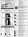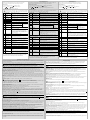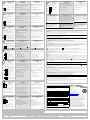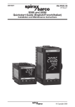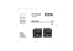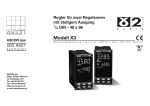
1
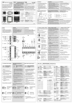
IM-P323-38 3231357/1 CH Issue 1 SX80 and SX90 Quickstart Guide (English/Spanish/German) Installation and Maintenance Instructions IM-XXXX-XX XX Issue X © Copyright 2013 1 Printed in France SX Series Controllers Installation ENG Serie SX Reguladores Instalación SPA Modelos SX80 y SX90 Models SX80 and SX90 e f c A SX90 e e d C D Latching ears e Panel Clips de sujeción retaining clips en panel Rückhalteklammern f Sleeve Gehäuse e c f Pestañas de cierre Außenklammern Junta sellante IP65 IP65 Dichtung Carcasa A 48mm (1.89inch) C 11mm (0.44 inch) B 96mm (3.78 inch) D 90mm (3.54 inch) También suministra Also supplied 2 x Snubber issue 7 Wiring 1. Bereiten Sie den Schalttafelausschnitt nach der untenstehenden Abbildung vor 2. Wenn nötig, montieren Sie die IP65 Dichtung hinter den Frontrahmen des Reglers. 3. Stecken Sie den Regler in den Tafelausschnitt. 4. Bringen Sie die Halteklammern an ihren Platz. Zum Sichern des Reglers halten Sie das Gerät in Position und schieben Sie beide Klammern gegen den Schalttafelausschnitt. 5. Lösen Sie die Schutzfolie von der Anzeige. Conexiones Los terminales roscados admiten cables con diámetros comprendidos entre 0,5 y 1,5 mm (16 a 22 AWG). El contacto accidental de manos o piezas metálicas con conductores activos se evita mediante tapas con bisagras. Los tornillos de los terminales posteriores deben estar apretados a un par de 0,4 Nm (3,5 lb in) . Die Schraubklemmen auf der Regler Rückseite sind für Kabelquerschnitte von 0,5 bis 1,5 mm2 vorgesehen (16 bis 22AWG). Die Klemmenleisten sind jeweils mit einer Kunststoffabdeckung zum Schutz vor Berührung versehen. Achten Sie beim Anziehen der Schrauben darauf, dass das Drehmoment 0,4 Nm nicht übersteigt. Disposición de Terminales + - 2 1A LA AA 1B LB AB 2A LC AC I 2B L 8 HE - N V HF To Remove the Controller from its Sleeve Ease the latching ears c outwards and pull the controller forward. When plugging back in ensure that the latching ears click into place to maintain the IP65 sealing + + 1 LC 1B LD 2A 2 LB + 3 - 7 I - - - OP2 is supplied as standard as a 4-20mA analogue output. For functionality see Quick Code Set 2. RTD / 4-20mA (mV) / TC + 4A AA 4B AB 4C AC 4 2A LB Com 5B RI LC 6 5C RC AA PH AB 3A I 3C V 12 HB PW HC PL HD VI L HE V+ N HF V- 1. Check order code of the controller supplied 2. Use copper conductors only. 3. The power supply input is not fuse protected. This should be provided externally. Safety requirements for permanently connected equipment state: 1. Antes de conectar el regulador a la red eléctrica, asegúrese de que la tensión de la red se ajusta a los parámetros descritos en la etiqueta de identificación. 2. Utilice únicamente conductores de cobre. 3. El suministro no incluye fusible de protección para la entrada de alimentación eléctrica. Esta protección será responsabilidad del usuario. • A switch or circuit breaker shall be Condiciones de seguridad para equipos con conexión permanente: • It shall be in close proximity to the • La instalación debe incluir un conmutador o un included in the building installation equipment and within easy reach of the operator • It shall be marked as the disconnecting device for the equipment. Note: a single switch or circuit breaker can drive more than one instrument. disyuntor. • Debe estar muy próximo al equipo y al alcance del operario. • Debe estar señalizado como sistema de desconexión para el equipo. Nota: Un solo conmutador o disyuntor puede dar servicio a más de un instrumento. + + Line L Linea N Neutral N Neutro • High voltage supply: 100 to 230Vac, +15%, • Alimentación de alta tensión: 100 a 230 V CA, 48 to 62 Hz • SX80 6 Watts max. SX90 9W max. • Recommended external fuse ratings are:- +15%, 48 a 62 Hz. • SX80 6 Watts max. SX90 9W max. • Los parámetros recomendados para fusibles externos son los siguientes: El fusible debe ser de tipo T y 2 A, 250 V. • Isolated output 240Vac • Contact rating: 2A 264Vac resistive - any terminal limited to 2A Transmitter Power Supply SX80 - - R =2.49Ω The transmitter power supply provides an 18V supply to power an external transmitter. 9 + HE - HF ! Achten Sie auf die richtige Spannungsversorgung für Ihren Regler. 1. Bevor Sie das Gerät an die Versorgungsspannung anschließen, überprüfen Sie, dass die Netzspannung der Gerätespannung (siehe Geräteaufkleber) entspricht. 2. Verwenden Sie nur Kupferleitungen. 3. Der Eingang der Spannungsversorgung ist intern nicht abgesichert. Bauen Sie eine externe Sicherung oder einen Unterbrechungskontakt ein. Sicherheitsanforderungen für permanent angeschlossene Anlagenbauteile: • Die Schaltschrankinstallation muss einen Schalter oder Unterbrechungskontakt beinhalten. • Dieses Bauteil sollte in der Nähe der Anlage und in direkter Reichweite des Bedieners sein. H 10mm (0.4in) Extracción del regulador de su carcasa El regulador se puede extraer de su carcasa abriendo las pestañas de cierre c y tirando de él hacia fuera. Si lo vuelve a introducir en la carcasa, asegúrese de volver a colocar las pestañas de cierre para conservar la protección IP65. Para ver las funciones de código inicio rápido. • Salida aislada de 240 V CA • Tipo de contacto: 2 A, 264 V CA resistivo Gewicht Reglerwechsel Durch Auseinanderziehen der Außenklammern c und nach vorne ziehen des Reglers können Sie das Gerät aus dem Gehäuse entnehmen. Wenn Sie das Gerät zurück in das Gehäuse stecken, versichern Sie sich, dass die Außenklammern einrasten. Salida de Relè (IO1) SX80 y SX90 Salida 1 se suministra de forma estándar como un relé normalmente abierto se configura para la temperatura de alarma. Peso 8.82oz (250g) Ausgang Relais (IO1) SX80 und SX90 Die Ausgänge können Logik (SSR gesteuert), Relais oder mA DC sein. Zusätzlich können sie den Logikausgang 1 als Schließkontakteingang verwenden. Für Funktionen siehe Quick Start Code • Isolierter Ausgang 240 V AC • Kontakt Nennwert: 2 A, 264 V AC ohm’sch Salida 2 (OP2) SX80 y SX90 Ausgang 2 (OP2) SX80 und SX90 OP2 se suministra como estándar como 420mA salida analógica. OP2 wird standardmäßig als 4-20mA AnalogAusgang geliefert. Para ver las funciones de código inicio rápido. Für Funktionen siehe Quick Start Code • Isolierter Ausgang 240 V AC • Es kann als 0-20mA oder 4-20mA konfiguriert werden Salidas 3 y 4 (OP3/4) solo SX80 Ausgänge 3 und 4 (OP3/4) SX80 nur Salidas 3 y 4 estan normalmente abierto (Forma A) relès que comparten una misma conexión. Ausgänge 3 und 4 sind Schließer (Form A) Relais mit einem gemeinsamen Common. Están destinadas a control de motor impulsado por las válvulas. Sie werden zur Regelung von Schrittmotoren verwendet. Para ver las funciones de código inicio rápido. Für Funktionen siehe Quick Code Set 2. • Salida aislada de 240 V CA • Tipo de contacto: 2 A, 264 V CA resistivo - • Isolierter Ausgang 240 V ac • Kontakt Nennwert: 2 A, 264 V ac ohm’sch Alimentación de Transmisor SX80 Transmitterversorgung SX80 cualquier terminales limitado a 2A - jede Klemme auf 2A begrenzt. • Spannungsversorgung: 100 bis 230 V ac, +15%, 48 bis 62 Hz • SX80 6 Watts max. SX90 9W max. • Externe Sicherungen: Sicherung Typ T, 2 A 250 V. • Salida aislada de 240 V CA • Salida 18V +15%, 30mA • Isolierter Ausgang 240 V ac • Ausgang: 18V +15%, 30mA Entrada de sensor (entrada de medida) SX80 y SX90 . Fühlereingang SX80 und SX90 • Verlegen Sie die Eingangskabel nicht • When shielded cable is used, it should • Si se utilizan cables apantallados, deben estar • Verwenden Sie abgeschirmte Leitungen, • Any external components (such as • Los componentes externos (como barreras • Externe Komponenten (wie z. B. Zener • Sensor input not isolated from the logic • Esta entrada no está aislada de las salidas • Nicht von Logikausgängen und be grounded at one point only zener barriers) connected between sensor and input terminals may cause errors in measurement due to excessive and/or un-balanced line resistance, or leakage currents outputs & digital inputs. Thermocouple Type K V+ + V- - RTD V- Phase Die Transmitterversorgung liefert 18V für die Versorgung eines externen Transmitters. • No ponga juntos los cables de entrada con los cables Anmerkung: Sie können einen Schalter oder Trennkontakt für mehrere Geräte verwenden. Neutral La alimentación de transmisor proporciona un suministro de 18V a un poder externo transmisor. • Do not run input wires with power • Kennzeichnen Sie dieses Bauteil als N • Isolated output 240Vac • Output 18V +15%, Sensor Input SX80 and SX90 9 VI L V 30mA Spannungsversorgung SX80 und SX90 trennende Einheit. L OP4 7 Compruebe que usa la alimentación correcta para su regulador. ! OP3 AC Alimentación Eléctrica del Regulador SX80 y SX90 Ensure that you have the correct supply for your controller 92mm (- 0.0 + 0.8) Weight 10 RTD / 4-20mA (mV) / TC Power Supply SX80 and SX90 38mm (1.5in) 1.77inch (-0.00, +0.02) Outputs 3 & 4 (OP3/4) SX80 only Outputs 3 and 4 are normally open (Form A) relays which share a common connection. They are intended to control motor driven valves. For function see Quick Code Set 2. 11 Abmessung G 4-20mA 3/4 RV V Dimensiones 45mm (- 0.0 + 0.6) • Isolated output 240Vac • Salida aislada de 240 V CA • Configurable 0-20mA or • Se puede configurar como 0-20mA o 4-20mA I 2B 5A I E Output 2 (OP2) 4-20mA SX80 and SX90 5 3D 8 264Vac resistive 2B 3B + • Isolated output 240Vac • Contact rating: 2A 2 9 (Nicht maßstabsgerecht) (No a escala) Relay Output (IO1) SX80 and SX90 1B 1A F 1A R =2.49Ω y Separación mínima recomendada 3.62 inch (-0.00, +0.03) 4 V- 7 SX90 SX90 G 1 Schalttafelausschnitte und Minimalabstände zwischen Reglern Tamaños de los cortes en el panel Dimensions SX80 Output 1 is supplied as standard as a normally open relay configured for temperature alarm. For alarm type see Quick Code Set 3. 3 V+ 5. Retire la cubierta protectora de la pantalla E H E VI + 4. Ponga en su lugar los clips de sujeción en el panel. Coloque el regulador manteniéndolo recto y empujando hacia delante los clips de sujeción. Panel Cut-out and Recommended Minimum Spacing (Not to scale) Klemmenbelegung SX80 1 3. Introduzca el regulador en la abertura. 5. Peel off the protective cover from the display Verdrahtung The screw terminals accept wire sizes from 0.5 to 1.5 mm (16 to 22AWG). Hinged covers prevent hands or metal making accidental contact with live wires. The rear terminal screws should be tightened to 0.4Nm (3.5lb in). Terminal Layout 2. Fije la junta sellante IP65 por detrás del bisel delantero del regulador. 4. Spring the panel retaining clips into place. Secure the controller in position by holding it level and pushing both retaining clips forward. F Kabelquerschnitt Fuse type: T rated 2A 250V 1. Realice un corte en el panel de montaje con el tamaño indicado en la ilustración. Si va a haber varios reguladores montados en el mismo panel, deje entre ellos la distancia mínima que se indica. 2. Fit the IP65 sealing gasket behind the front bezel of the controller 03/13 Tamaños de cables ! 1. Cut out the panel to the size shown. E Wire Sizes 8 Dieses Gerät ist für den festen Einbau in eine elektrische Schalttafel im Innenbereich vorgesehen. 2 X RC-Glied (HA029849ESG/7 CN29611) Installation Este instrumento está pensado para su instalación permanente, sólo en interiores y dentro de un panel eléctrico. Ebenfalls 2 X amortiguador Instalación This instrument is intended for permanent installation, for indoor use only, and enclosed in an electrical panel. 1 x 2.49Ω resistor 1 x 2,49Ω resistencia 1 X 2,49Ω Widerstand e d IM-P323-32 Part No. 3231351 Packungsinhalt IP65 Sealing Gasket Installation 3. Insert the controller in its sleeve through the cut-out. c d e B Funktionen, die nicht in dieser Anleitung erwähnt werden, finden Sie im Konfigurations Handbuch, Bestellnummer 3231354 http://www.SpiraxSarco.com Desembalaje del regulador Unpacking the Controller A Für die Modelle SX80 und SX90 Si desea información sobre funciones especiales no incluidas en esta Guía del usuario, puede descargar un Manual de ingeniería detallado, Referencia 3231354, y otros documentos relacionados en la dirección Web. http://www.SpiraxSarco.com For features not covered in this User Guide, a detailed Engineering Manual, Part No 3231354, and other related handbooks can be downloaded from http://www.SpiraxSarco.com SX80 Serie SX Regler Installation GER • Use the correct compensating cable preferably shielded. • The resistance of the three wires must be the same. The line resistance may cause errors if it exceeds 22Ω. V+ cables de alimentación eléctrica conectados a tierra en un solo punto Zener, etc.) conectados entre los terminales de entrada y los sensores pueden producir errores en la medida debido a una resistencia de línea excesiva y/o desequilibrada o a posibles corrientes de fuga lógicas y las entradas digitales. zusammen mit Versorgungskabeln erden Sie diese nur an einem Ende Dioden) zwischen Fühler und Eingangsklemmen können aufgrund von erhöhtem und/oder unsymmetrischen Leitungswiderständen oder Leckströmen Messfehler verursachen Digitaleingängen isoliert. Termopar Tipo K Thermoelementeingang Typ K • Use el tipo correcto de cable de • Verwenden Sie die passende compensación, preferiblemente apantallado. Ausgleichsleitung. Diese sollte möglichst geschirmt sein. RTD RTD Eingang • La resistencia debe ser la misma para los tres • Der Widerstand aller drei Leitungen muss V- Compensación de carga. V+ y VI PRT. V- Leitungskompensation. V+ and VI PRT. Lineales de mA o mV Linear mA, mV oder Spannungseingänge • -10 a 80mV • Por la entrada de mA sólo se debe conectar • -10 bis 80mV • Nur für mA Eingänge: schließen Sie den hilos. La resistencia de línea puede producir errores si es mayor que 22 Ω. gleich sein. Ein Leitungswiderstand größer 22 Ω kann Fehler verursachen. V- Lead compensation. V+ and VI PRT. Linear mA or mV V+ V- + R - • -10 to 80mV • For mA input only connect the 2.49Ω (R) resistor supplied between the V+ and Vterminals as shown. una resistencia de carga de 2,49 Ω entre los terminales V+ y V-, tal como se observa en la ilustración. mitgelieferten 2,49 Ω Widerstand über die Klemmen V+ und V-. Operator Level 2 Bedienebene 2 Nivel de Operario 2 Parameters are available in deeper levels of access protected by security codes. Level 2 parameters are typically used when commissioning the controller. To Select Level 2 Los parámetros están disponibles en niveles más profundos de acceso protegidos por códigos de seguridad. Nivel 2 normalmente permite el acceso a encargar tipo de parámetros. Parameter stehen Ihnen unter verschiedenen Sicherheitsebenen zur Verfügung. Para Seleccionar el Nivel 2 Zugriff auf Ebene 2 In Ebene 2 können Sie die für die Inbetriebnahme wichtigen Parameter einstellen. bis LEv1 angezeigt wird. los und wählen Sie mit ▲ oder ▼ Lev 2 (Ebene 2). Geben Sie mit ▲ oder ▼ das Passwort ein. Vorgabe = ‘2 1. Drücken und halten Sie 1. From any display press and hold 1. Desde cualquier pantalla mantener pulsados 2. Release 2. Suelte 2. Lassen Sie 3. 3. until LEv1 is shown and press ▲ or ▼ to choose Lev 2 (Level 2) Press ▲ or ▼ to enter the pass code. Default = ‘2 3. hasta que se demuestre LEv1. y pulse ▲ o ▼ para seleccionar Lev 2 (Nivel 2) Pulse ▲ o ▼ para introducir el código de seguridad. Código predeterminado = “2” Ebene 2 Parameter Level 2 Parameters Parámetros del nivel 2 Press to step through a list of parameters. After 5 seconds the parameter mnemonic is followed by a scrolling description. Press ▲ or ▼ to adjust the value of the parameter. Pulse para desplazarse por la lista de parámetros. Cinco segundos después aparece también un texto de descripción. Pulse ▲ o ▼ para ajustar el valor del parámetro. Mit können Sie nacheinander alle Parameter aufrufen. Nach 5 s erscheint zusätzlich zur Mnemonic eine durchlaufende Beschreibung des Parameters. Mit ▲ oder ▼ können Sie den Wert verändern. Mnemo Scrolling Text nic Mnemo Mensaje técnica Rango. Ajuste usando ▲ o ▼ Mnemo Durchlaufender nik Text Bereich. Mit ▲ oder ▼ können Sie den Wert ändern. WRK.OP WORKING OUTPUT Active output value. Shown when the controller is in AUTO or OFF mode. Read only. WRK.OP SALIDA OPERATIVA El valor de la salida activa. Se muestra cuando el regulador está en modo OFF o AUTO. Sólo lectura. WRK.OP ARBEITSAUSGANG Ist der Ausgang des Reglers. Erscheint nur, wenn der Regler im Automatikmodus ist. Schreibgeschützt. WRK.SP WORKING SETPOINT Active setpoint value (SP1, SP2, SP3 or REM.SP). Shown when the controller is in MAN or OFF mode. Read only WRK.SP PUNTO DE CONSIGNA OPERATIVO El valor del punto de consigna activo (SP1 or SP2). Se muestra cuando el regulador está en modo OFF o MAN. Sólo lectura. WRK.SP ARBEITSSOLLWERT Ist der aktuelle Zielsollwert (SP1, SP2, SP3 oder REM.SP). Erscheint, wenn der Regler im Handbetrieb oder OFF arbeitet. Schreibgeschützt. UNITS oC, oF, ok, UNITS UNIDADES DE MEDIDA oC, oF, ok, UNITS ANZEIGE EINHEIT oC, oF, ok, SP.HI PUNTO DE CONSIGNA SUPERIOR/INFERIOR Límite superior/ inferior aplicado a los puntos de consigna SP1, SP2, SP3 y Consigna Remoto REM.SP. SP.HI OBERE SOLLWERTGRENZE Obere Grenze / untere Grenze für SP1, SP2, SP3 und Externer Sollwerteingang REM.SP. Punto de consigna 1, 2 o 3 ajustar. Modificable entre SP.HI y SP.LO SP.LO SOLLWERT UNTERE GRENZE Ajusta aumento de la tasa de cambio de SP. Modificable: De OFF a 3000 unidades/minuto. SP1/2/3 SOLLWERT 1, 2, 3 Wert für Sollwert 1, 2 oder 3. Änderbar SP.HI bis SP.LO. SP.RRT SOLLWERTRAMPE SP.FRT SOLLWERTRAMPE Einstellung der Änderungsrate für Bei Einstellung auf einen Wert, den Sollwert - Erhöhung. leuchtet ‚RUN’ wenn der Sollwert Einstellung der Änderungsrate für geändert wird. DISPLAY UNITS SP.HI SETPOINT HIGH SP.LO SETPOINT LOW Range. Adjust using ▲ or ▼ none, perc (%) High and low setpoint limit applied to SP1, SP2, SP3 and Remote Setpoint REM.SP. SP1/2/3 SETPOINT 1, 2 or 3 Setpoint 1, 2 or 3 adjust. Alterable between SP.HI and SP.LO. SP.RRT SETPOINT RISING RATE LIMIT SP.FRT SETPOINT FALLING Sets decreasing rate of change of SP. RATE LIMIT Alterable: OFF to 3000 units/min. HOLD.B HOLDBACK TM.CFG TIMER CONFIGURATION Sets increasing rate of change of SP. Alterable: OFF to 3000 units/min. When set to a value, ‘RUN’ illuminates when the setpoint is changed. SX90 only. Stops the setpoint ramp if deviation between SP and PV > the set value. Range OFF or 1 to 9999. SP.LO SP1/2/3 PUNTO DE CONSIGNA 1/2/3 SP.RRT SP.FRT LÍMITE DE VARIACIÓN DE PUNTO DE CONSIGNA MTR.T MOTOR TRAVEL TIME A.TUNE AUTO-TUNE ENABLE xx = HI (high), LO (low), D.HI (deviation high), D.LO (deviation low), BND (deviation band). Alterable over the controller range. Set this to the time taken for the motor to travel from fully closed to fully open. 0.0 to 999.9 seconds. Automatically sets the control parameters to match the process characteristics. Set to On to start the process. PROPORTIONAL BAND 1 to 9999 display units TI INTEGRAL TIME 1 to 9999 seconds. OFF can be set if control type = PID. Default: 360. TD DERIVATIVE TIME OFF, 1 to 9999 seconds. Default:: 60 for PID. MR MANUAL RESET R2G RELATIVE COOL GAIN PB D.BAND CHANNEL 2 DEADBAND Default: 20. RUN se encenderá cuando el punto ha sido cambiada. HOLD.B RETENCIÓN SX90 solo. Detiene el rampa en caso de desviación entre SP y PV > el valor ajustado. Rango OFF o 1 a 9999. TM.CFG CONFIGURACIÓN DE TEMPORIZADOR none = niguno Further parameters are shown if soft start is configured. See note 1. A1/2.xx ALARM 1/2 SETPOINT (if configured) Ajusta la disminución de la tasa de cambio de SP. Modificable: De OFF a 3000 unidades/minuto. none = no timer configured SF.St = A soft start timer starts automatically on power up. It applies a power limit (SS.PWR) until the PV reaches a threshold value or the timer times out (DWELL). The threshold value = WKG.SP - SS.SP. It does not operate with boundless valve position. none, perc (%) SF.St = Un temporizador de inicio suave se pone en marcha automáticamente al encender y aplica un límite de potencia (“SS.PWR”) hasta que la temperatura alcanza un valor umbral. Valor umbral = WKG.SP - SS.SP. MTR.T (si se configura) Modificables sobre el rango de regulador. TIEMPO DE RECORRIDO DEL MOTOR Defina este valor en relación con el tiempo que tarda la válvula en pasar de posición totalmente abierta a posición totalmente cerrada. 0,0 a 999,9 segundos. A.TUNE AUTOAJUSTE Configura automáticamente los parámetros de control para que se ajusten a las características del proceso. On = inicar el processo. TM.CFG TIMER KONFIGURATION none = Keine SF.St = Ein Soft Start Timer startet automatisch beim Einschalten des Reglers. Der Timer schaltet dem Ausgang eine Leistungsbegrenzung (‘SS.PWR’) auf, bis die Temperatur den Schwellwert (‘SS.SP’) erreicht hat oder die Timerzeit (‘DWELL’) abgelaufen ist. Schwellwert = WKG.SP - SS.SP. Es funktioniert nicht mit Offener Schrittregelung. Weitere Parameter werden angezeigt, wenn ein Soft Start Timer konfiguriert ist. Siehe Anmerkung 1. xx = HI (Maximalalarm), LO (Minimalalarm), D.HI (Abweichung Hoch), A1/2.xx ALARM 1/2 SOLLWERT D.LO (Abweichung Tief), BND (Abweichungsbandalarm). (wenn konfiguriert) Veränderbar über die Bereich des Regler. MTR.T MOTORLAUFZEIT A.TUNE FREIGABE Eingabe der Zeit, die der Motor benötigt, um die Klappe von voll geschlossener Position aus zu öffnen. 0,0 bis 999,9 Sekunden. Automatische Anpassung der Regelparameter an die Prozess SELBSTOPTIMIERUNG Charakteristik. Zum Starten des Prozesses auf ON setzen. PB BANDA PROPORCIONAL De 1 a 9999 unidades de medida. Valor Predeterminado: 20. TI TEMPO INTEGRAL De 1 a 9999 segundos. OFF se puede establecer si el tipo de control = PID. Valor Predeterminado: 360. PB PROPORTIONAL BAND 1 bis 9999 Anzeigeeinheiten Not for VP. Otherwise range -100.0 to 100.0% TD TIEMPO DERIVATIVO OFF, De 1 a 9999 segundos. Valor Predeterminado: 60 para PID. TI INTEGRALZEIT Adjusts the cooling proportional band relative to the heating proportional band. Heat/cool only. Range 0.1 to 10.0. Default 1.0. MR REINICIO MANUAL No para VP. Del -100,0 al 100,0% 1 bis 9999 Sekunden. Bei Regelart = PID kann auch OFF eingestellt werden. Vorgabe: 360 R2G GANANCIA RELATIVA DE Permite ajustar la banda proporcional de enfriamiento con FRÍO respecto a la banda proporcional de calentamiento. Sólo Calor/Frío. Rango 0,1 a 10,0. Predeterminado: 1,0. Sets a zone between heating and cooling outputs when neither output is on. Quick Code Function 2 = A only. Range OFF or 0.1 to 100.0% of the cooling proportional band. These parameters are further described in manual HA027986. Note 1: TM.RES, TIMER RESOLUTION; SS.PWR, SOFT START POWER LIMIT; SS.SP, SOFT START SETPOINT; DWELL, SET TIME DURATION; T.REM, TIME REMAINING. D.BAND BANDA MUERTA DE CANAL 2 Define una zona, entre las salidas de calentamiento y enfriamiento, en que ninguna de ellas está activada. Código de Pedido 2 = A sólo. Rango OFF o del 0,1 al 100,0% de la banda proporcional de enfriamiento. Estas características se describen en detalle en el manual HA027986. Nota 1: TM.RES, TIMER RESOLUTION; SS.PWR, SOFT START POWER LIMIT; SS.SP, SOFT START SETPOINT; DWELL, SET TIME DURATION; T.REM, TIME REMAINING. ! El uso de este instrumento de manera distinta a lo especificado puede suponer un riesgo parameter la seguridad o reducir el grado de protección EMC. El instalador deberá garantizar la seguridad y la compatibilidad EMC de todas las instalaciones. Seguridad. Este regulador cumple la Directiva Europea sobre Baja Tensión 2006/95/EC, con la aplicación de la normativa de seguridad EN 61010. Desembalaje y almacenamiento. Si recibe el instrumento con daños en el embalaje, no instale el producto y póngase en contacto con su proveedor. Si el instrumento va a permanecer almacenado antes de su uso, protéjalo del polvo y la humedad a una temperatura ambiente entre -30o C y +75o C. Precauciones contra descargas electrostáticas. Siempre electrostática observar todas las precauciones antes de manipular la unidad. Mantenimiento y reparaciones. Este regulador no tiene ninguna pieza que pueda ser objeto de mantenimiento. Póngase en contacto con su proveedor en caso de que sea necesaria una reparación. Limpieza. No emplee agua ni productos acuosos para limpiar las etiquetas, ya que podrían llegar a resultar ilegibles. Puede limpiar las etiquetas con alcohol isopropílico. Otras superficies exteriores del producto se pueden limpiar con una solución jabonosa suave. Compatibilidad electromagnética (EMC). Este regulador satisface los requisitos básicos de protección de la Directiva sobre EMC 2004/108/EC, con la aplicación de un Expediente Técnico de Construcción. Este instrumento satisface los requisitos generales del entorno industrial definido en EN 61326. Precaución: Condensadores cargados. Antes de retirar el instrumento de su carcasa, desconecte la alimentación eléctrica y espere al menos dos minutos para que se descarguen los condensadores. Evite tocar los componentes electrónicos expuestos de un instrumento cuando lo extraiga de la carcasa. Símbolos de seguridad. En el regulador se utilizan distintos símbolos que tienen el significado siguiente: ! Precaución (consulte la documentación adjunta) Equipo totalmente protegido con DOBLE AISLAMIENTO Categoría de instalación y Grado de contaminación. Este producto ha sido diseñado de acuerdo con BSEN61010 para categoría de instalación II, grado de contaminación 2. Estas categorías se definen como sigue: • Categoría de instalación II (CAT II). La tensión nominal impulsiva para equipos con alimentación nominal de 230 V es de 2.500 V. • Grado de contaminación 2. Normalmente sólo se genera contaminación no conductiva. No obstante, en ocasiones se debe esperar una conductividad temporal causada por condensación. Personal. La instalación sólo podrá ser llevada a cabo por personal debidamente capacitado. Aislamiento de partes activas. Para impedir que las manos o las herramientas metálicas entren en contacto con partes o elementos eléctricamente activos, el regulador deberá ser instalado en un cajetín cerrado. Precaución: Sensores activos. El regulador está diseñado para operar conjuntamente con el sensor de temperatura conectado directamente a un elemento eléctrico calefactor. No obstante, deberá asegurarse de que el personal de mantenimiento no toque las conexiones a estas entradas mientras se hallen activas. Si un sensor está activo, todos los cables, conectores y conmutadores utilizados para la conexión del sensor deberán ser específicos para la red eléctrica utilizada (230 V CA +15%, CATII). Conexiones. Es importante que el regulador esté conectado de acuerdo con la información sobre conexiones contenida en esta guía. Asegúrese de que la conexión a tierra es SIEMPRE equipados primera y última desconectado y asegúrese de que la instalación cumple todas las normativas locales sobre conexiones. En el Reino Unido, por ejemplo, siga la última versión de las normativas sobre conexiones del IEE (BS7671); en los Estados Unidos hay que utilizar métodos de conexión NEC Clase 1. No conecte alimentación CA a la entrada de sensor de baja tensión o a cualquier otra entrada y salida de bajo nivel. Tensión límite. La máxima tensión continua aplicada entre cualesquiera de los siguientes terminales no debe superar los 230 V CA +15%,: • Salida de relé a conexiones lógicas, CC o de sensores. • Cualquier conexión a tierra. DIFFERENTIALZEIT Off bis 9999 Sekunden. Vorgabe: 60 für PID. MR MANUAL RESET Nicht für VP. Anderenfalls Bereich -100.0 bis 100.0%. R2G RELATIVE KUEHLVERSTÄRKUNG Justiert das Kühlen Proportionalband relativ zum Heizen Proportionalband. Nur Heizen/Kühlen. 0,1 bis 10.0. Vorgabe 1.0. D.BAND KANAL 2 TOTBAND Ist der Bereich zwischen Heizen und Kühlen, wenn kein Ausgang eingeschaltet ist. Nur Bestellcodierung 2 = A. OFF oder 0.1 bis 100.0% des Kühlen Proportionalbands. Diese Parameter finden Sie im Handbuch HA027986 näher beschrieben. Anmerkung 1: TM.RES, TIMER RESOLUTION; SS.PWR, SOFT START POWER LIMIT; SS.SP, SOFT START SETPOINT; DWELL, SET TIME DURATION; T.REM, TIME REMAINING. Protección contra temperaturas excesivas. Para evitar el sobrecalentamiento del proceso de avería, un exceso de temperatura unidad de protección debe estar equipado que aislar el circuito de calefacción. Este debe tener un sensor de temperatura independiente. Nota: Tenga en cuenta que los relés de alarma del regulador no dan protección contra este tipo de fallos Requisitos sobre EMC para la instalación. Para garantizar el cumplimiento de la Directiva Europea sobre EMC es necesario tomar ciertas precauciones durante la instalación: filtro dependerán del tipo de carga. Sicherheit und EMV Dieses Gerät ist für die Verwendung in industriellen Temperatur- und Prozessregelanlagen vorgesehen und entspricht den Anforderungen der Europäischen Richtlinien für Sicherheit und EMV. Die Informationen in dieser Anleitung können ohne Hinweis geändert werden. Wir bemühen uns um die Richtigkeit der Angaben in dieser Anleitung. Der Lieferant kann nicht für in der Anleitung enthaltene Fehler verantwortlich gemacht werden. ! Verwenden Sie das Gerät nicht nach den hier gegebenen Anweisungen, können Sicherheit und EMV beeinträchtigt werden. Sicherheit. Dieser Regler entspricht den Europäischen Richtlinien für Sicherheit und EMV 2006/95/EC. Es liegt in der Verantwortung des Inbetriebnehmers, diese Richtlinien bei der Installation des Geräts einzuhalten. Auspacken Und Lagerung. Ist bei Empfang die Packung oder das Gerät beschädigt, sollten Sie den Regler NICHT einbauen und den Hersteller benachrichtigen. Lagern Sie das Gerät vor Feuchtigkeit geschützt bei einer Umgebungstemperatur zwischen -30 ºC und +75 ºC. Elektrostatische Entladung. Haben Sie den Regler aus dem Gehäuse entfernt, können einige der freiliegenden Bauteile durch elektrostatische Entladungen beschädigt werden. Beachten Sie deshalb alle Vorsichtsmaßnahmen bezüglich statischer Entladungen Service und Reparatur. Dieses Gerät ist wartungsfrei. Sollte das Gerät einen Fehler aufweisen, kontaktieren Sie bitte die nächste Eurotherm Niederlassung. Reinigung. Verwenden Sie für die Reinigung der Geräteaufkleber kein Wasser oder auf Wasser basierende Reinigungsmittel sondern Isopropyl Alkohol. Die Oberfläche der Geräte können Sie mit einer milden Seifenlösung reinigen. Elektromagnetische Verträglichkeit. Dieser Regler ist konform zu der EMV Richtlinie 2004/108/EC, und den erforderlichen Schutzanforderungen. Das Gerät entspricht den allgemeinen Richtlinien für industrielle Umgebung, definiert in EN 61326. Achtung: Geladene Kondensatoren. Bevor Sie den Regler aus dem Gehäuse entfernen, nehmen Sie das Gerät vom Netz und warten Sie etwa 2 Minuten, damit sich Kondensatoren entladen können. Vermeiden Sie jeden Kontakt mit der Elektronik, wenn das Gerät aus dem Gehäuse entfernen. Sicherheits Symbole. Im Folgenden werden die auf dem Gerät angebrachten Sicherheits-Symbole erklärt: ! Achtung, (siehe dazugehörige Dokumentation) Bauteile sind durch DOPPELTE ISOLIERUNG geschützt Überspannungskategorie und Verschmutzungsgrad. Dieses Produkt entspricht EN61010, Überspannungskategorie II und Verschmutzungsgrad 2. Diese sind wie folgt definiert: • Überspannungskategorie II. 2500 V Steh-Stoßspannung bei 230 Vac Nennspannung. • Verschmutzungsgrad 2. Übliche, nicht leitfähige Verschmutzung; gelegentlich muss mit vorübergehender Leitfähigkeit durch Betauung gerechnet werden. Personal. Lassen Sie die Installation des Geräts nur von qualifiziertem Fachpersonal durchführen. . Berührung Bauen Sie den Regler zum Schutz vor Berührung in ein Gehäuse ein. Achtung: Fühler unter Spannung. Der Regler ist so konstruiert, dass der Temperaturfühler direkt mit einem elektrischen Heizelement verbunden werden kann. Es liegt in Ihrer Verantwortung dafür zu sorgen, dass Servicepersonal nicht an unter Spannung stehende Elemente gelangen kann. Ist der Fühler mit dem Heizelement verbunden, müssen alle Leitungen, Anschlüsse und Schalter, die mit dem Fühler verbunden sind, für 230 V ac +15% CATII ausgestattet sein. . Verdrahtung Die Verdrahtung muss korrekt, entsprechend dieser Anleitung und den jeweils gültigen Vorschriften erfolgen. Die Schutzerde muss IMMER als Erstes angeschlossen und als Letztes abgetrennt werden. Verwenden Sie ausschließlich Kupferleitungen. Das Drehmoment für die Anschlussklemmen beträgt 0,4 Nm max. ! Verbinden Sie die AC Versorgung NICHT mit Niederspannungs Fühlereingängen oder mit anderen Niederspannungs Ein- oder Ausgängen. Maximalspannungen. Die maximal anliegende Spannung der folgenden Klemmen muss weniger als 230 V ac +15% betragen: No se debe conectar el regulador a una alimentación trifásica con una conexión en estrella sin toma de tierra, ya que en caso de avería la tensión de alimentación podría superar los 240 V CA con respecto a tierra y el producto no estaría seguro. Contaminación conductiva. Se debe eliminar la contaminación eléctricamente conductiva de la cabina en que se haya instalado el regulador. Para conseguir una atmósfera adecuada, instale un filtro de aire en la toma de aire de la cabina. Si existe posibilidad de condensación (por ejemplo, a bajas temperaturas), incluya en la cabina un calefactor controlado por termostato. Conexión a tierra de la pantalla del sensor de temperatura. En algunas instalaciones es habitual cambiar el sensor de temperatura con el regulador encendido. En estas condiciones es recomendable conectar a tierra la pantalla del sensor de temperatura como medida de protección adicional contra choques eléctricos. La conexión a tierra a través del bastidor de la máquina puede no ser suficiente. • Consulte las directrices generales en la Guía de instalación para EMC de Eurotherm, HA025464. • Si se emplean salidas de relé puede ser necesario instalar un filtro adecuado para suprimir las emisiones. Vorgabe: 20 TD Información sobre seguridad y EMC Este regulador está pensado para aplicaciones industriales de control de procesos y temperatura en cumplimiento de los requisitos de las Directivas Europeas sobre Seguridad y EMC La información contenida en este manual puede ser modificada sin previo aviso. Aunque hemos hecho todo lo posible para garantizar la exactitud de la información, su proveedor no podrá ser considerado responsable de ningún error que pueda contener este manual. ! Änderbar: OFF bis 3000 Anzeigeeinheiten pro Minute. Nur SX90 . Stoppt die Sollwertrampe, wenn die Abweichung zwischen SP und PV den eingestellten Wert überschreitet. Bereich OFF oder 1 bis 9999. Otros parámetros se muestran si un temporizador de inicio suave está configurado. Consulte la nota 1. xx = HI (alta), LO (bassa), D.HI (desviación alta), D.LO (desviación bassa), BND (banda de desviación). den Sollwert - abnehmend. HOLD.B HOLDBACK No operar para control sin límites de la posición de la válvula. A1/2.xx PUNTO DE CONSIGNA DE ALARMA 1/2 none, perc (%) • Relaisausgang zu Logik-, DC oder Fühlerverbindungen; • jede Verbindung gegen Erde. Schließen Sie den Regler nicht an Drehstromnetze ohne geerdeten Mittelpunkt an. Im Falle eines Fehlers kann es bei dieser Versorgung zu Spannungen über 264 V ac kommen. Das Gerät kann dadurch zerstört werden. . Umgebung Leitende Verschmutzungen dürfen nicht in den Schaltschrank gelangen. Um eine geeignete Umgebungsluft zu erreichen, bauen Sie einen Luftfilter in den Lufteintritt des Schaltschranks ein. Sollte das System in kondensierender Umgebung stehen (niedrige Temperatur), bauen Sie eine thermostatgeregelte Heizung in den Schaltschrank ein. Erdung des Temperaturfühlerschirms. In manchen Anwendungen wird der Sensor bei laufendem System gewechselt. In diesem Fall sollten Sie als zusätzlichen Schutz vor Stromschlag den Schirm des Temperatursensors erden. Verbinden Sie den Schirm nicht mit dem Maschinengehäuse. Anlagen- und Personensicherheit. Um eine Überhitzung des Prozesses unter fehlerhaften Bedingungen zu vermeiden, sollten Sie eine unabhängige Temperatur Schutzeinheit zur Isolierung des Heizkreises einbauen. Achtung: Das Alarmrelais dient nicht zum Schutz der Anlage, sondern nur zum Erkennen und Anzeigen der Alarme. EMV Installationshinweise. Um sicherzustellen, dass die EMV-Anforderungen eingehalten werden, treffen Sie folgende Maßnahmen: Las condiciones que deba cumplir el • Si la unidad se utiliza con equipos de sobremesa conectados a una toma de corriente estándar, lo más probable es que sea necesario cumplir las normativas sobre emisiones para el comercio y las industrias ligeras. En este caso se deberá instalar un filtro de red adecuado para las emisiones conductivas. • Stellen Sie sicher, dass die Installation gemäß den "EMV-Installationshinweisen", Bestellnummer HA150976, durchgeführt wird. • Bei Relaisausgängen müssen Sie eventuell einen Filter einsetzen, um die Störaussendung zu unterdrücken. • Verwenden Sie den Regler in einem Tischgehäuse, sind unter Umständen die Anforderungen der Fachgrundnorm EN 50081-1 gültig. diesem Fall einen passenden Filter in das Gehäuse ein. Bauen Sie in Output 3 (OP3) 4-20mA SX90 only 3 OP3 is a 4-20mA analogue output in SX90 only. For functionality see Quick Code, Code 2. + • Isolated output 240Vac • Configurable 0-20mA or 3A - 3B 4-20mA Salida 3 (OP3) SX90 sólo Ausgang 3 (OP3) Nur SX90 OP3 es un 4-20mA salida analógica en sólo SX90. OP3 ist ein 4-20mA Analogausgang nur im SX90. Para ver las funciones de código inicio rápido. Für Funktionen siehe Quick Start Code. • Salida aislada de 240 V CA • Se puede configurar como 0-20mA o 4-20mA • Isolierter Ausgang 240 V AC • Es kann als 0-20mA oder 4-20mA konfiguriert werden Digital Communications SX90 only 12 Digital communications uses Modbus protocol. It is available in SX90 only as EIA422 (EIA485 5-wire). Rx+(A) HB Rx-(B) HC Com. HD Tx+(A) HE Tx-(B) 4 Output 4 (OP4) Salida 4 (OP4) SX90 only SX90 sólo Ausgang 4 (OP4) SX90 Output 4 is a changeover (Form C) relay fitted in SX90 only. Salida 4 es un paso (Forma C) relé instalado en sólo SX90. Ausgang 4 ist fest eingebauter Wechsler (Form C) nur in SX90. For functionality see Quick Start, Code 4. Para ver las funciones de código inicio rápido. Für Funktionen siehe Quick Start Code. • Salida aislada de 240 V CA • Tipo de contacto: 2 A, 264 V CA resistivo • Isolierter Ausgang 240 V AC. • Kontakt Nennwert: 2 A, 264 V AC • Isolated output 240Vac • Contact rating: 2A AA AB 264Vac resistive AC Outputs 5 & 6 (OP5/6) SX90 only 5/6 Outputs 5 and 6 are supplied as normally open (Form A) relays and are to control motor driven valves. They share a common connection and are, therefore, not isolated from each other. For alarm type see Quick Code, Code 3. 5A • Isolated output 240Vac • Contact rating: 2A OP5 5B OP6 5C 264Vac resistive - any terminal limited to 2A Salidas 5 y 6 (OP5/6) SX90 sólo The transmitter power supply provides a supply to power an external transmitter. + 3C - 3D Ausgänge 5 und 6 (OP5/6) SX90 nur Salidas 5 y 6 estan normalmente abierto (Forma A) relés que comparten una misma conexión. Son, por tanto, no aislados unos de otros. Ausgänge 5 und 6 sind Schließer (Form A) Relais mit einem gemeinsamen Common. Sie sind daher nicht isoliert von einander. Están destinadas a control de motor impulsado por las válvulas. Für Funktionen siehe Quick Code Set 3. • Salida aislada de 240 V CA • Tipo de contacto: 2 A, 264 V CA resistivo cualquier terminales limitado a 2A Alimentación de Transmisor SX90 sólo Transmitter Power Supply SX90 only 7 La alimentación de transmisor proporciona un suministro de 18V a un poder externo. • Isolated output 240Vac • Salida aislada de 240 V CA Sortie 18V +1V • Output 24V +10%, 30mA • Salida 18V +10%, 30mA V ohm’sch. Sie dienen der Regelung von Schrittmotoren. • Isolierter Ausgang 240 V AC • Kontakt Nennwert: 2 A, 264 V AC ohm’sch - Jede Klemme ist auf 2A begrenzt. Transmitterversorgung SX90 nur Die Transmitterversorgung liefert für die Versorgung eines externen Transmitters. • Isolierter Ausgang 240 V AC • Ausgang: 24V +10%, 30mA Comunicaciones Digitales SX90 sólo • EIA422 or EIA485 (5wire) • Isolated 240Vac. Digitale Kommunikation SX90 nur Las comunicaciones digitales utilizan el protocolo Modbus. Está disponible en SX90 sólo como EIA422 (EIA485 de 5 hilos). Die digitale Kommunikation verwendet das Modbus Protokoll. Im SX90 steht es nur als EIA422 (EIA485 5-Draht) zur Verfügung. • EIA422 o EIA485 (5- hilos) • Aislada de 240 V CA. • EIA422 oder EIA485 (5-Leiter) • Isoliert 240V AC. HF General Notes about Relays and Inductive Loads Notas generales sobre relés y cargas inductivas When switching inductive loads such as contactors or solenoid valves, wire the 22nF/100Ω ‘snubber’ supplied across the normally open relay terminals. This will prolong contact life and reduce interference. Cuando se conmuten cargas inductivas como contactores o válvulas de solenoie de 22nF/100Ω los ‘snubber’ suministrados deben conectarse en las terminales AA & AB. Esto prolongara la vida del contacto y suprimirá interferencias. ! WARNING Snubbers pass 0.6mA at 110V and 1.2mA at 230Vac, which may be sufficient to hold on high impedance loads. Do not use in these installations. ! ¡Advertencia! Snubbers pasando 0,6mA a 110V y 1.2mA a 230Vca, puede ser suficiente para mantener cargas de alta impedancia. No usar en esas instalacioneso Allgemeine Anmerkungen über Relais und induktive Lasten Beim Schalten induktiver Lasten (Schütze), verbinden Sie die Klemmen AA und AB mit einem 22nF/100Ω RC-Glied. Dieses erhöht die Lebensdauer des Kontaktes und unterdrückt Störspitzen. ! WARNUNG Bei geöffnetem Relaiskontakt fließen über den RC-Kreis 0,6mA bei 110Vac und 1,2mA bei 240Vac. Achten Sie darauf, dass durch diesen Strom keine niedrigen Lasten angezogen werden. Safety and EMC Information This instrument is intended for industrial temperature and process control applications within the requirements of the European Directives on Safety and EMC. The information contained in this manual is subject to change without notice. While every effort has been made to ensure the accuracy of the information, your supplier shall not be held liable for errors contained herein. ! The safety and EMC protection can be seriously impaired if the unit is not used in the manner specified. The installer must ensure the safety and EMC of the installation. Safety. This instrument complies with the European Low Voltage Directive 2006/95/EC, by the application of the safety standard EN 61010. Unpacking and storage. If on receipt, the packaging or unit is damaged, do not install but contact your supplier. If being stored before use, protect from humidity and dust in an ambient temperature range of -30oC to +75oC. Electrostatic discharge precautions. Always observe all electrostatic precautions before handling the unit. Service and repair. This instrument has no user serviceable parts. Contact your supplier for repair. Cleaning. Isopropyl alcohol may be used to clean labels. Do not use water or water based products. A mild soap solution may be used to clean other exterior surfaces. Electromagnetic compatibility. This instrument conforms with the essential protection requirements of the EMC Directive 2004/108/EC, by the application of a Technical Construction File. It satisfies the general requirements of the industrial environment defined in EN 61326. Caution: Charged capacitors. Before removing an instrument from its sleeve, disconnect the supply and wait at least two minutes to allow capacitors to discharge. Avoid touching the exposed electronics of an instrument when withdrawing it from the sleeve. Safety Symbols. Symbols used on the instrument have the following meaning: ! LA Digital Inputs A & B : SX80 LB For functionality refer to the User Manual HA029899. • Switching: LA LA LB LC LA 12Vdc at 12mA max LB • Contact open > 1200Ω. Contact closed < 300Ω • Conmutación: • Schalten: LA 12 V CC a 12 mA máx. LA 12 V DC bei 12 mA max LB 12V CC a 40mA LB 12V DC bei 40mA • Contacto abierto >1200 Ω. • Kontakt offen > 1200 Ω. Contacto cerrado < 300 Ω Kontakt geschlossen < 300 Ω Entradas Digitales A y B SX90 sólo Digitaleingänge A & B Nur SX90 Estos son libres voltios cierre de contacto insumos que pueden utilizarse para Auto / Manual seleccionar o reconocer la alarma. Dies sind spannungsfreie Schließkontakt Eingänge für die Auto/Hand Auswahl oder zur Alarmbestätigung. For functionality refer to the Engineering Manual HA029899. Para ver la funcionalidad de manual HA029899. Für Funktionen siehe Handbuch HA029899. • No está aislado de la entrada del sensor. • LC y LD no aislados unos de otros • Conmutación: • Nicht vom Fühlereingang isoliert. • LC-LD und nicht voneinander isoliert • Schalten: • Not isolated from the sensor input • LC and LD not isolated from each other 4A • Switching: 4C LC/LD 12Vdc at 6mA max LB 12Vdc at 12mA 4B LD Für Funktionen siehe Handbuch HA029899. These are volt free contact closure inputs which may be used for Auto/Manual select or alarm acknowledge. LC LC Para ver la funcionalidad de manual HA029899. Digital Inputs B. C & D SX90 only LB LB Digitaleingänge A e B : SX80 LB 12Vdc at 40mA LC LB LC LD Entradas Digitales A & B : SX80 LB 12V DC bei 12mA • Kontakt offen > 1200 Ω. Contacto cerrado < 300 Ω Kontakt geschlossen < 300 Ω Contact closed < 300Ω Entrada Potenciómetro SX90 sólo Potentiometer Input SX90 only 10 LC/LD 12 V DC bei 6 mA max LB 12V CC a 12mA • Contacto abierto >1200 Ω. • Contact open > 1200Ω. 4C LC/LD 12 V CC a 6 mA máx. PH The potentiometer input provides feedback of the valve position PW PL • Potentiometer resistance: 100-10kΩ • Excitation voltage: 0.46 to 0.54V • Short circuit detection: <25Ω • Open circuit detection: >2MΩ • Open circuit wiper detection >5MΩ Potentiometer Eingang Nur SX90 El potenciómetro de entrada proporciona información de la posición de la válvula Caution, refer to accompanying documents) Equipment protected throughout by DOUBLE INSULATION Installation Category and Pollution Degree. This unit has been designed to conform to BSEN61010 installation category II and pollution degree 2, defined as follows:- • Installation Category II (CAT II). The rated impulse voltage for equipment on nominal 230V supply is 2500V. • Pollution Degree 2. Normally only non conductive pollution occurs. However, a temporary conductivity caused by condensation must be expected. Personnel. Installation must only be carried out by suitably qualified personnel Enclosure of Live Parts. To prevent hands or metal tools touching parts that may be electrically live, the controller must be installed in an enclosure. Caution: Live sensors. The controller is designed to operate if the temperature sensor is connected directly to an electrical heating element. However, you must ensure that service personnel do not touch connections to these inputs while they are live. With a live sensor, all cables, connectors and switches for connecting the sensor must be mains rated for use in 230Vac +15% CATII. Wiring. It is important to connect the unit in accordance with the data in this sheet ensuring that the protective earth connection is ALWAYS fitted first and disconnected last. Wiring must comply with all local wiring regulations, i.e. UK, the latest IEE wiring regulations, (BS7671), and USA, NEC Class 1 wiring methods. ! Do not connect AC supply to low voltage sensor input or low level inputs and outputs. Voltage rating. The maximum continuous voltage applied between any of the following terminals must not exceed 230Vac +15%: • relay output to logic, dc or sensor connections; • any connection to ground. The controller must not be wired to a three phase supply with an unearthed star connection. Electrically conductive pollution i.e. carbon dust, MUST be excluded from the enclosure in which the controller is installed. To secure a suitable atmosphere in conditions of conductive pollution, fit an air filter to the air intake of the enclosure. Where condensation is likely, include a thermostatically controlled heater in the enclosure. Grounding of the temperature sensor shield. In some installations it is common practice to replace the temperature sensor while the controller is still powered up. Under these conditions, as additional protection against electric shock, we recommend that the shield of the temperature sensor is grounded. Do not rely on grounding through the framework of the machine. Over Temperature Protection. To prevent overheating of the process under fault conditions, a separate over-temperature protection unit should be fitted which will isolate the heating circuit. This must have an independent temperature sensor. Note: Alarm relays within the unit will not give protection under all failure conditions. Installation Requirements for EMC. To comply with European EMC directive certain installation precautions are necessary:- • General guidance. Refer to EMC Installation Guide, Part no. HA025464. • Relay outputs. It may be necessary to fit a suitable filter to suppress conducted emissions. • Table top installation. If using a standard power socket, compliance with commercial and light industrial emissions standard is usually required. To comply with conducted emissions standard, a suitable mains filter must be installed. Der Potentiometereingang liefert eine Rückmeldungen der Klappenposition. • Resistencia de potenciómetro: 100-10kΩ • Voltaje de excitación: 0,46 para 0,54V • Ejemplos de tasa: 1Hz • Corto circuito de detección: <25Ω • Abrir el circuito de detección: >2MΩ • Detección de circuito abierto >5MΩ • Potentiometer Widerstand: 100-10kΩ • Spannungsversorgung 0,46 bis 0,54V • Abtastrate 1Hz • Kurzschluss-Erkennung <25Ω • Leerlauf Erkennung: >2MΩ • Leerlauf Abnehmer Erkennung >5MΩ Zone industrielle nord Product group RV RI RC Entrada de punto de consigna remoto SX90 sólo Remote Setpoint Input SX90 only 0-10V 4-20 mA I V • C = Common • Isolated 240Vac C • There are two inputs; 4-20mA (terminals RC and RI) and 0-10 Volts (terminals RC and RV). • C = Commun • Aislada de 240 V CA • Hay dos entradas; 4-20mA (terminales RC y RI) y voltios (terminales RC y RV) • No es necesario instalar una resistencia de carga en la entrada de 4-20mA Externer Sollwerteingang Nur SX90 • C = Common • Isolierter 240 V AC • Zwei Eingänge, 4-20 mA (Klemmenbelegung RC und RI) und Spannung (Klemmenbelegung RC und RV), • Ein externer Widerstand für den 4-20 mA 15 rue louis bleriot SX80, SX90 BP329 Table listing restricted substances Chinese 铅 X O O 印刷线路板组件 附属物 显示器 O 86103 Chatellerault 限制使用材料一览表 产品 SX80, SX90 X 11 Address Restriction of Hazardous Substances (RoHS) 汞 O O O 镉 X O O 有毒有害物质或元素 六价铬 O O O 多溴联苯 O O O 表示该有毒有害物质在该部件所有均质材料中的含量均在SJ/T11363-2006 标准规定的限量要求以下。 表示该有毒有害物质至少在该部件的某一均质材料中的含量超出SJ/T11363-2006 标准规定的限量要求。 Restricted Materials Table Product SX80, SX90 PCBA Enclosure Display O X Pb X O O Hg O O O Toxic and hazardous substances and elements Cd Cr(VI) PBB X O O O O O O O O Approval Name: Position: Martin Greenhalgh Quality Manager Signature: IA029559U600 (CN24442) Issue 1 May 08 Especificaciones Generales PBDE O O O Indicates that this toxic or hazardous substance contained in all of the homogeneous materials for this part is below the limit requirement in SJ/T11363-2006. Indicates that this toxic or hazardous substance contained in at least one of the homogeneous materials used for this part is above the limit requirement in SJ/T11363-2006. burden resistor to the 4-20mA input General Specification France Tel: 00 33 (0)5 49 20 03 40 Web [email protected] http://www.SpiraxSarco.com © Copyright 2008 Spirax-Sarco Spirax Sarco is a registered trademark of Spirax-Sarco Limited. English Eingang ist nicht nötig. • It is not necessary to fit an external 多溴二苯醚 O O O Date: All rights are strictly reserved. No part of this document may be reproduced, modified or transmitted in any form by any means, nor may it be stored in a retrieval system other than for the purpose to act as an aid in operating the equipment to which the document relates, without the prior written permission of the manufacturer. The manufacturer pursues a policy of continuous development and product improvement. The specification in this document may, therefore, change without notice. The information in this document is given in good faith, but it is intended for guidance only. The manufacturer will accept no responsibility for any loses arising from errors in this document. Allgemein Operating ambient 0 to 55°C, 32 to 131°F, and RH: 5 to 85% non-condensing. Ambiente de operación 0 a 55°C, 32 a 131°F, y 5 to 85% de humedad relativa sin condensación. Betriebsumgebung 0 bis 55°C, 32 bis 131°F, und 5 bis 85 % relative Feuchte, nicht kondensierend Panel Sealing IP65, plug in from front panel Protección de panel IP65, desde el panel frontal Schutzart IP65, frontseitig einsteckbar Atmospheres Not suitable for use above 2000m or in explosive or corrosive atmospheres Atmósferas No se debe usar por encima de 2.000 m ni en atmósferas explosivas o corrosivas Atmosphäre Nur geeignet für den Betrieb in Bereichen unter 2000 m, in nicht explosiver oder korrosiver Umgebung Switch On Encendido If the controller has not previously been configured it will start up, showing the ‘Quick Configuration’ codes. Erste Konfiguration Si el regulador no ha sido configurado previamente, arrancará mostrando los códigos de “Configuración rápida”. se t 1 se t 1 ***** La rápida código consta de 5 caracteres en el formato: 12345 12345 This allows input and output functionality to be configured as in shown in the table below. The second character defines the control type and hence the output type. ***** The third character defines the function of the alarm relay. Der Quick Code besteht aus fünf Zeichen im Format: The fourth character defines the function of Output 4 in SX90. 12345 Esta herramienta integrada le permite Mit dieser eingebauten Funktion configurar el tipo y rango de entrada, las können Sie Eingangsart und –bereich, funciones de salida y el formato de die Ausgangsfunktionen und das pantalla.. Anzeigeformat konfigurieren. ! Incorrect configuration can result in damage to the process and/or personal injury and must be carried out by a competent person authorised to do so. It is the responsibility of the person commissioning the controller to ensure the configuration is correct. Una configuración incorrecta puede dañar el proceso y/o producir lesiones al personal. La configuración debe ser realizada únicamente por personas competentes y autorizadas. La persona que ponga en servicio el regulador tendrá la responsabilidad de garantizar que está bien configurado. The fifth character defines the language used for User Messages. If the controller has been previously configured using the Quick Codes, it will start up showing the ‘HOME display’ shown below. Si el regulador se ha configurado con anterioridad utilizando el Quick códigos, se iniciará mostrando la 'pantalla HOME' se muestra a continuación. Quick Code Functions Eine nicht korrekte Konfiguration kann zu Beschädigungen des Prozesses und zu Personenschäden führen. Es liegt in der Verantwortung des Inbetriebnehmers, für eine korrekte Konfiguration zu sorgen. 3. Press to scroll to the next character. need to return to the first character press . 4. When all five characters have been configured press again, the display will show 1. Tipo de entrada y rango 1. Eingangsart und Bereich Alarm relay on IO1 (SX80 & SX90) Alarm relay on IO1. Analogue feedback Alarm relay on IO1. Potentiometer feedback Alarm relay on IO1 Alarm relay on OP4 Alarm relay on IO1 Alarm relay on OP4 Das vierte Zeichen definiert die Funktion des Ausgangs 4 im SX90. El quinto personaje se define el lenguaje utilizado para los mensajes del usuario. Das fünfte Zeichen definiert die verwendete Sprache für die User-Meldungen. . ▲ ▼ o para cambiar el carácter que parpadea 2. Pulse al código que se indica en la tabla de códigos de inicio 3. Pulse ▲ or ▼ to . 2 3 4 x indica . 4. Una vez configurados los cinco caracteres vuelva a pulsar . Example 4. Haben Sie alle fünf Stellen konfiguriert drücken Sie . Die Anzeige zeigt ▲ oder Ejemplo ▼ . pa01e Beispiel 2. Regelaktion und Ein/Aus Geschlossenen Regelung OP3/4 (SX80) Geschlossenen Regelung OP5/6 (SX90) Nur SX90 Offene Schrittregelung OP5/6 Nur SX90 Offene Schrittregelung OP5/6 Nur SX90 Analog Heizen/Kühlen PID-Ausgang auf OP2/OP3 Analog Heizen nur PID-Ausgang auf OP2 (SX80) Folgen OP2/OP3 (SX90) Relé de alarma en IO1 (SX80 & SX90) Relé de alarma en IO1 Analógico retroalimentación Relé de alarma en IO1 Potenciómetro retroalimentación Relé de alarma en IO1 Relé de alarma en OP4 Relé de alarma en IO1 Relé de alarma en OP4 Alarmrelais - IO1 (SX80 & SX90) Alarmrelais - IO1 Rückführ Analog Alarmrelais - IO1 Rückführ Potentiometer Alarmrelais - IO1 Alarmrelais - OP4 Alarmrelais - IO1 Alarmrelais - OP4 PT100 RTD K K t/c -200 - 1372 OC 0 4-20mA 0-1.60 BAR 1 4-20mA 0-2.50 BAR 2 4-20mA 0-4.00 BAR 3 4-20mA 0-6.00 BAR 4 4-20mA 0-10.00 BAR 5 4-20mA 0-16.00 BAR 3. IO1 alarm relay 3. IO1 Relé de alarma 3. IO1 Alarmrelais 4. OP4 alarm relay (not if SX80 and VP) 4. OP4 Relé de alarma (si no SX80 y VP) 4. OP4 Alarmrelais (nicht wenn SX80 oder VP) 6 4-20mA 0-25.00 BAR X Unconfigured Sin configurar Kein Alarm konfiguriert X Unconfigured Sin configurar 7 4-20mA 0-40.00 BAR 0 Full scale high Absoluta alta Vollbereichsmaximalalarm 0 Full scale high Absoluta alta Vollbereichsmaximalalarm 8 4-20mA -50 -500 OC Full scale low Absoluta bassa Vollbereichsminimalalarm Absoluta bassa Vollbereichsminimalalarm 4-20mA 0 - 100 OC 1 Full scale low 9 1 2 Deviation high 2 Deviation high 3 Deviation low 3 Deviation low Desviación baja Abw. Tief 4 Deviation band 4 Deviation band Banda de desviación Abw. Band 4-20mA 100 - 250 OC HOME Display manual Desviación alta latching Desviación baja Retención Abw. Hoch manual Abw. Tief Banda de desviación INICIO (HOME) SX80 Abw. Band HAUPTANZEIGE ➀ ➀ ➁ ➂ ➃ ➀ ➀ ➅ If you need to re-enter the ‘Quick Configuration’ mode this can always be done by powering down the controller, holding down the button, and powering up the controller again. You must then enter a passcode ▼ ▲ or buttons. In using the a new controller the passcode defaults to 4. If an incorrect passcode is entered you must repeat the whole procedure. Regreso al modo de configuración rápida En caso necesario, puede volver en cualquier momento al modo de configuración rápida. Para ello basta con apagar el regulador, mantener pulsado el botón y volver a encender el regulador. A continuación hay que introducir un código de acceso ▼ ▲ empleando los botones o . En un regulador nuevo, el código de acceso predeterminado es 4. Si introduce un código de acceso incorrecto, deberá repetir todo el procedimiento. Operation Por defecto, los siguientes ajustes se pueden hacer en Operador de Nivel 1. To Adjust the Setpoint Ajuste el Punto de Consigna Von der Hauptanzeige: The new setpoint is entered when the button is released and is indicated by a brief flash of the display. For remote setpoint see the User Manual HA029889. Auto/Manual/OFF Mode In the HOME display:Press and hold ▼ AND ▲ (Mode) together for more than 1 second. Press ▲ to select Manual (man), Off (Off) and Auto (Auto). In Manual (or OFF) mode, MAN will be lit. When in Manual press ▼ or ▲ to decrease or increase output power. Pulse ▲ para subir el punto de Pulse ▼ para bajar el punto de consigna Encendido si la salida 2 está activa - enfriamiento o reducir. Leuchtet, wenn Ausgang 2 EIN ist - Kühlen oder Schließen. ➃ ➄ OP4 Not used No se utilisza Nicht verwendet ▲ erhöhen Sie den Sollwert. Mit ▼ verringern Sie den Sollwert. Mit consigna El nuevo punto de consigna se acepta al soltar el botón; esto se indica con un breve parpadeo en la pantalla. Para el punto de consigna remoto mirar el manual de usuario HA029889. Der neue Sollwert wird vom Gerät übernommen, sobald Sie die Taste loslassen. Ein kurzes Aufblinken zeigt Ihnen, dass der Wert jetzt aktuell ist. Externer Sollwert siehe Benutzerhandbuch HA029889. Modo Automático/Manual/ Desactivado Auto/Hand/Aus Desde la pantalla de INICIO:Mantenga pulsados ▼ y ▲ (Modo) simultáneamente durante más de 1 segundo. Pulse ▲ para seleccionar “mAn”. Vuelva a pulsarlo para elegir el modo Desactivado. En modo Manual (o OFF) estará encendido el indicador MAN. Pulse ▼ o ▲ para aumentar o reducir la salida. Von der Hauptanzeige: Halten Sie ▼ und ▲ (Mode) für mehr als 1 s gedrückt. Wählen Sie mit ▲ ‘mAn’. Durch erneutes Drücken erscheint ‘OFF. Im Handbetrieb (oder OFF) leuchtet die MAN. Mit ▼ oder ▲ können Sie die Leistung verändern. Anzeigen:- Lit when output 2 is ON - cool or lower. OP3 SPX Alternative setpoint in use (SP2 or SP3) Punto de consigna alternativo en uso (SP2 o SP3) Alternativer Sollwert (SP2 oder SP3) REM Remote setpoint or communications active Comunicaciones o punto de consigna remoto activo Externer Sollwert oder Kommunikation aktiv RUN Soft start timer running Temporizador de inicio suave en funcionamiento Soft Start Timer läuft RUN (flashing) Soft start timer in hold (parpadeando) Temporizador de inicio suave retenido (blinkt) Soft Start Timer angehalten MAN Manual mode selected Modo manual seleccionado Handbetrieb ➁ ➂ Units (if configured) Unidades (en caso de configurarse) Einheiten (wenn konfiguriert) Measured Value (Temperature or Pressure) La Temperatura o la presión medida Gemessene Temperatur oder Druck ➃ Target Temperature or Pressure (Setpoint) La Temperatura o la presión requerida (punto de consigna) por defecto. Ziel Temperatur oder Druck (Sollwert ) ➄ Meter (SX90 only) Defaults to Valve Position if Quick Code 2 is D, V or B. Medidor (sólo en SX90) Meter (nur SX90) Defaults to Heat/Cool (centre zero) if Quick Code 2 is A or H. Por defecto es la posición de la válvula si el Codice ‘Quick Start’ 2 es D, V y B. Standardmäßig Klappenposition, wenn ‘Quick Start’ 2 ist D, V oder B. Por defecto es calor / frio si el Codice ‘Quick Start’ 2 es A o H. Standardmäßig Heizen/Kühlen wenn ‘Quick Start’ 2 ist A oder H. by default Standardmäßig. ➅ Operator Buttons Botones del operario Bedientasten From any display - press to return to the HOME display. Para volver a la pantalla de INICIO desde cualquier pantalla Mit dieser Taste kommen Sie aus jeder Ansicht zurück in die Hauptanzeige Press to select a new parameter. Hold down to continuously scroll through parameters. Para seleccionar un nuevo parámetro. Si se mantiene pulsado, para pasar de un parámetro a otro Diese Taste dient der Auswahl eines Parameters. Halten Sie die Taste gedrückt, laufen die Parameter durch ▼ ▲ Press to decrease a value. Para cambiar o reducir un valor Taste zum Ändern/Verringern eines Werts. Press to increase a value. Para cambiar o aumentar un valor Taste zum Ändern/Erhöhen eines Werts. Examples in the use of these buttons are shown in following sections Ejemplos en el uso de estos botones se muestran en las Beispiele im Umgang mit diesen Tasten werden in secciones siguientes folgenden Abschnitten gezeigt. Alarm Indication The red ALM beacon will flash. A scrolling text message will describe the source of the alarm. Any output attached to the alarm will operate (deenergise) by default. Indicación de Alarma El indicador rojo ALM parpadeará, aparecerá un mensaje indicando el origen de la alarma y se accionará la salida que esté conectada a la alarma. Para Reconocer la Alarma To acknowledge the alarm: Einstellen des Sollwerts En la pantalla de INICIO (HOME): ▲ to raise the setpoint Press ▼ to lower the setpoint Press Deutsch OP2 Bedienung In the HOME display:- Italiano G ➁ ➂ Folgende Einstellungen können Sie standardmäßig in Ebene 1 durchführen. Nur lokaler Sollwert. Español I Leuchtet, wenn Ausgang 1 EIN ist - Heizen oder Öffnen ein. In einem neuen Regler ist das werksseitig eingestellte Passwort 4. Haben Sie ein falsches Passwort eingegeben, müssen Sie die gesamte Prozedur wiederholen. Haben Sie das Passwort richtig eingegeben, können Sie mit Hilfe des Quick Codes den Regler neu konfigurieren. Solo punto de consigna local. Français S Encendido si la salida 1 está activa - calentamiento o aumentar. ▼ oder ▲ Tasten das Passwort Local setpoint only. Indicadores:- Beacons:- F Lit when output 1 is ON - heat or raise. (Ziel Temperatur/Druck) Manuelles Rücksetzen OP1 gedrückter Taste das Gerät wieder einschalten. Halten Sie die Taste so lange gedrückt, bis ‘c o d e ’ erscheint. Geben Sie dann mit den (Temperatura/Presión Requerida) Abw. Hoch Alarm aktiv (Rot) Sie können jederzeit wieder auf den Quick Code Modus zugreifen, indem Sie den Regler abschalten und mit (Target Temperature/Pressure) Retención manual Alarma activa (color rojo) Erneutes Aufrufen des Quick Code Modus Funcionamiento By default the following settings can be made in Operator Level 1. Desviación alta 5. Language 5. Idioma 5. Sprache E English Alarm active (Red) ➅ To Re-Enter Quick Code configuration mode manual latching Kein Alarm konfiguriert ALM SX90 ➀ Manuelles Rücksetzen Möchten . Der Regler geht automatisch in die Bedienebene 1. El regulador pasará automáticamente al Nivel de Operario 1. 5 2. Tipo de controlar y entrada/salida Control sin límites de la posición de la válvula a OP3/4 (SX80) Control sin límites de la posición de la válvula a OP5/6 (SX90) SX90 sólo Control con límites de la posición de la válvula a OP5/6 SX90 sólo Control con límites de la posición de la válvula a OP5/6 SX90 sólo Analógico de calor / frío PID a la salida OP2/OP3 Analógico de calor sólo PID a la salida OP2 (SX80) Seguimento OP2 OP3 (SX90) rufen Sie die nächste Stelle auf. Wählen Sie mit . ▼ Sie zur ersten Stelle zurück, drücken Sie erneut La pantalla mostrará ▲ o ▼para ▲ 2. Ändern Sie mit oder die blinkende Stelle, bis der gewünschte Code erscheint (Quick Code Tabelle unten). Anmerkung: X bedeutet, dass die Option nicht eingebaut ist. 3. Mit para pasar al siguiente carácter. Si necesita volver al primer carácter, pulse 1. Drücken Sie eine Taste. Das erste Zeichen wechselt auf ein blinkendes ‘-‘. P A 99.9 - 300.0OC 1 Bestellcodierung 2. Control type and I/O D Boundless VP, on OP3/4 (SX80) Boundless VP, on OP5/6 (SX90) V SX90 only Bounded VP on OP5/6 P SX90 only Bounded VP on OP5/6 A SX90 only Analogue Heat/Cool PID output on OP2/OP3 H Analogue Heat only PID output on OP2 (SX80) OP2 tracks OP3 (SX90) 1. Input type and range El cuarto personaje se define la función del Producto 4 a SX90. Pulse Press Das zweite Zeichen definiert die Regelart und somit auch die Art des Ausgangs. Das dritte Zeichen legt die Funktion des Alarmrelais fest. rápido (consulte a continuación). Nota: Una que la opción no está configurada. If you XXXXX El tercer personaje define la función del relé de alarma 1. Pulse cualquier botón El primer carácter cambiará a un “-” intermitente. The controller will then automatically start in Código de Pedido El segundo carácter se define el tipo de control y, por tanto, el tipo de salida. Para ajustar estos números, siga este procedimiento: functions – see table below. Note: An x indicates that the option is not fitted. Wurde der Regler bereits zuvor über den Quick Code konfiguriert, zeigt er bei einem erneuten Einschalten direkt die ‘Hauptanzeige’. El primer carácter se define el tipo de entrada. 1. Press any button. The first character will change to a flashing ‘-‘. or to change the flashing character 2. Press to the required code shown in the quick code Bei der ersten Einschalten erscheint: Das erste Zeichen definiert die Eingangsart. Adjust these as follows:- ▲ ▼ ! Der Quick Code XXXXX The first character defines the input type. . ! Código de Inicio Rápido Al primero de conmutación en los personajes se muestran como: XXXXX se t 1 ***** The quick code consists of 5 characters in the format:- Quick Code When first switched on the characters are shown as: Haben Sie einen unkonfigurierten Regler, zeigt dieser beim ersten Einschalten den ‘Quick Konfiguration’ Code. Press AND (ACK) together By default alarms are configured as manual latching, and can only be reset when the alarm condition is no longer present. Operator Parameters in Level 1 Press to select:- WRK.OP WORKING OUTPUT If in AUTO mode WRK.SP WORKING SETPOINT If in MAN mode Both WRK.OP & WRK.SP are shown if in OFF mode. SP1/2/3 SETPOINT 1, 2 or 3 Press ▲ or ▼ to adjust the value A1/2.xx ALARM 1/2 SETPOINT (if configured) xx = Alarm type. HI - High; LO - Low; D.HI - Deviation high; D.LO - Deviation low; BND - Deviation band WRK.OP, WRK.SP & Alarm setpoints are read only. To adjust alarm setpoints, select Operator Level 2. Pulse y (Ack) De manera predeterminada, las alarmas están configuradas como alarmas con retención manual. El reconocimiento sólo puede tener lugar DESPUÉS de que se haya eliminado la condición que ha causado la alarma. Alarmanzeige Blinkt die rote ALM Anzeige, wird der Alarmausgang (Relais) geschaltet und eine durchlaufende Meldung erscheint auf der Anzeige. Dieser Meldung können Sie die Quelle des Alarms entnehmen. Den Alarm Bestätigen Drücken Sie gleichzeitig Ab Werk sind die Alarme als nicht gespeichert und im Alarmfall stromlos konfiguriert. Parámetros del Nivel 1 de Operario Pulse para seleccionar:- WRK.OP WRK.SP SALIDA OPERATIVA PUNTO DE CONSIGNA OPERATIVO Bedienparameter in Ebene 1 Wählen Sie mit Si en el modo AUTO Si en el modo MAN Ambos WRK.OP & WRK.SP si se muestran en el modo OFF SP1/2/3 PUNTO DE CONSIGNA PULSE ▲ o ▼ para 1, 2 o 3 ajustar este valor A1/2.xx ALARMA 1/2 (si se configura) xx = Tipo de alarma. HI - Alta; LO - Baja; D.HI - Desviación alta; D.LO - Desviación baja; BND - Banda de desviación WRK.OP, WRK.SP & punto de consigna de alarma sólo lectura. Para ajustar la consigna de alarmas, seleccione el nivel 2. und (ACK) Steht der Alarm weiterhin an, leuchtet die Alarmanzeige kontinuierlich weiter. :- WRK.OP ARBEITSAUSGANG Wenn im AUTO Modus WRK.SP ARBEITSSOLLWERT Wenn im MAN Modus Im OFF Modus werden WRK.OP & WRK.SP angezeigt SP1/2/3 SOLLWERT 1, 2 Mit ▲ oder ▼ können oder 3 Sie den Wert ändern. A1/2.xx ALARM 1/2 SOLLWERT (wenn konfiguriert) xx = Alarmart. HI - Maximalalarm; LO - Minimalalarm; D.HI Abweichung Hoch; D.LO - Abweichung Tief; BND - Abweichung Band WRK.OP, WRK.SP & Alarmsollwerte sind schreibgeschützt. Zur Änderung der Alarmsollwerte, Wählen Sie Ebene 2.