1
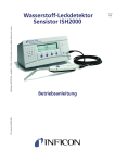
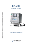
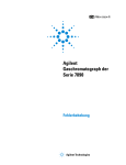
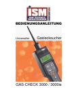
Publication: INFICON AB - ning69e2-a (1108) - All information can be modified without prior notice
AP57
C OUNTER F LOW P ROBE
User’s manual
Benutzerhandbuch
AP57
C OUNTER F LOW P ROBE
User’s manual
EN
Contents
2
1.1.
General .......................................................................................................................................... 3
1.2.
Main parts ..................................................................................................................................... 3
1.3.
Installation ..................................................................................................................................... 4
1.4.
Controls and Indicators ................................................................................................................. 4
1.5.
Operating the AP57. ...................................................................................................................... 5
1.6.
Troube shooting ............................................................................................................................ 7
1.7.
Pneumatic and electric diagram .................................................................................................... 8
1.8.
Technical specification.................................................................................................................. 9
INFICON – User’s manual AP57
EN
AP57 Counter Flow Probe
1.1.
General
AP57 is an accessory to INFICON Hydrogen Leak
Detector Sensistor ISH2000 that can be used
instead of the standard Hand Probe H50. The
AP57 probe is meant to be used on objects were
excessive leaks could be suspected, or in areas
were tracer gas not easily could be ventilated
away.
AP57 features:
•
•
•
•
•
Locates micro leaks in extremely high
backgrounds.
Pinpoints leaks in confined spaces and
cavities.
Locates a micro leak only millimetres away
from a gross leak.
Switching between two separately adjustable
flows could be done from the hand probe.
Leak alarm and Flow ON indicators in the
probe handle.
The tip diameter of the standard probe (H50) is
8mm. This is sometimes too big to allow leak
detection in constricted areas. The solution to this
is to have a sniffing probe with a long narrow tube
at its end.
SAFETY!
Pure hydrogen is a flammable gas. Only use
ready-made mixtures of 5% Hydrogen in
Nitrogen. This is a standard industrial gas
mixture used in various industrial applications.
Whenever the word Hydrogen is used
throughout this manual it implies that the
hydrogen gas is safely mixed with
Nitrogen in the proportions 5% H 2 - 95% N 2
Never use pure Hydrogen for leak testing!
A typical application is leak location on
combustion engines rejected by a previous
pressure decay test.
To be able to utilise all the functions of the
instrument, read this guide and the Hydrogen Leak
Detector Sensistor ISH2000 user manual carefully,
before using the equipment.
The Sensistor ISH2000 detector has two main
functions:
Detection Mode and Analysis Mode.
Used together with an AP57 the Sensistor
ISH2000 should be in the detection mode.
Detection mode is used to quickly detect and
locate a leak.
In Detection Mode, the signal is shown as a
moving bar and as an audio signal. The frequency
of the audio signal directly reflects the gas
concentration, which allows the user to work
without having visual contact with the display.
For gas concentrations equal to or above the set
LEAK ALARM level a red LED indicator will
illuminate both on the hand probe and on the AP57
front panel.
1.2.
Main parts
Control Box
APC57
Hand Probe H55
Fluid Cable FC21
Signal Cable C21S 0,3m
Bus Cable BC15
INFICON – User’s manual AP57
3
EN
1.3.
Installation
Important!
CAUTION!
The 25-pin D-type connector on the back of the
Leak Detector is not a computer or printer port.
Connecting a printer or any other computer device
may cause permanent damage to the connected
device.
Always switch power off before disconnecting or
connecting any cable.
• Always connect the probe and the cables before
starting the instrument.
• Never pull out the probe cable when the
instrument is in operation.
• Never put the probe in water or any other liquid.
1.4.
Controls and Indicators
2
5
3
1
Follow the instruction below to connect the AP57
system to the Sensistor ISH2000 Leak Detector.
Connecting Sensistor ISH2000 and probe:
1.
Place the controller (APC57) on a flat surface.
Put the detector (Sensistor ISH2000) on top of
the controller.
2.
Connect the bus cable (BC15) between the 25pin D-type ports on the back of the units.
3.
Connect the sensor cable (C21) between the
corresponding connectors on the front of the
units.
4.
Connect the fluid cable (FC21) to the port on
the front of the APC57.
5.
Connect the hand probe (H55) to the fluid
cable.
6.
Connect a hose to the fresh air inlet on the
back of the unit; the remote end of this hose
should be placed in an environment free from
tracer gas.
4
APC57 Control Box:
1)
2)
3)
4)
5)
6)
Power On LED
Counter Flow ON/OFF switch
Flow A LED
Flow B LED
Flow A Throttle valve
Flow B Throttle valve
Hand Probe:
7)
8)
9)
Accept Indicator
(Green)
Reject Indicator
(Red)
Push-button – toggles between Flow A and Flow B
8
7
9
4
INFICON – User’s manual AP57
6
EN
1.5.
Operating the AP57.
Application example:
Truck engines in an engine production plant are
leak tested in a pressure decay station. Leaking
engines are diverted to a repair line where the
leaks are located and repaired.
Step by step locating procedure:
Find a leak representing the smallest single leak
you need to locate.
(Alternately use a reference leak or throttle
valve to set up the same flow).
Charge the leak with tracer gas.
•
Start the Sensistor ISH2000 and set it in
detection mode and sensitivity = 10.
•
Fully open (counter clockwise) flow throttle
valve A on the APC57 panel.
•
Start the AP57 flow A and hold the probe
tip right on the opening of the leak.
•
Close throttle valve A until the detector
starts rising.
•
Open the throttle valve slightly until the
signal starts falling again. Lock the set
screw with the nut.
You have now adjusted the AP57 probe so that
Flow A will screen acceptable leaks, i.e. leaks
that should not be repaired.
Flow B can be used in to ways:
1) Either close flow throttle valve B fully. In
this case you can use the switch on the
handle to switch between no flow (B) and
leak screening flow (A).
2) You can instead use flow B for suppressing
very high backgrounds if that is a problem.
In this case you should adjust flow B so that
you can easily and precisely locate the leaks
you need to locate.
3) For highest possible sensitivity you would
then instead have to switch the flow off with
the switch on the APC57 panel.
INFICON – User’s manual AP57
5
EN
Locating the leak:
•
•
•
First try to locate the leak with no counter
flow in the probe. This gives highest
sensitivity.
If precise location is difficult switch flow A
on, or if necessary switch on flow B and
adjust the flow until signal is zero close to
the suspect area.
If counter flow is high you may need to put
the tip of the probe right on the leak, flat on
the surface to pick the leak up. Location
will be very precise. Leak will be detected
if within the rim of the probe tip and not
detected if outside that rim.
NOTE! Probe can be used with or without
protective filter installed in tip. Flow adjustment
is normally a bit easier if no filter is used!
6
INFICON – User’s manual AP57
Approx: 6 mm
EN
1.6.
Troube shooting
Problem
Probable cause
Actions
No signal when
exposed to gas.
Counter flow too high.
Check that compressed air is within limits (4.5 – 8 bar)
Sensor saturated.
Check that exhaust line is not blocked. Any connected
hose must have at least 4 mm inner diameter. Very long
hoses should have larger diameter.
Probe tip clogged
Check white plastic probe tip protection filter.
Remove the probe tip protection. Use a sharp pin or
needle to remove the filter and check if alarm goes off.
NOTE! Remember to install new protection filter.
Tip protection filter part number:590-625 (500 pcs)
Check condition of brass filter in tip. If clogged send
probe to service.
Check sample hose and probe tip for damage. Replace
damaged parts.
Sensitivity can not be
adjusted by adjusting
flow.
Main flow switch is off.
Set flow switch to ON
No power to the APC57 Check that the Bus Cable is properly connected.
controller
Detector gives signal
all the time.
Pump is not running
Check pump. Turn flow switch ON and OFF. You should
be able to hear the pump start.
Pump part number: T.B.D.
Internal filter clogged.
Open controller and inspect filter.
Filter part number: 591-276
High background
concentration of
hydrogen.
Increase counter flow.
Improve ventilation
Decrease tracer gas leakage from connectors etc.
Detector gives signal
every time flow is
turned OFF
High background of
Hydrogen.
This is normal in a high background. Flow should be on
all the time when locating leaks in high hydrogen
backgrounds.
INFICON – User’s manual AP57
7
EN
1.7.
8
Pneumatic and electric diagram
INFICON – User’s manual AP57
EN
1.8.
Technical specification
General
Dimensions:
275 x 205 x 100 mm.
Weight:
6 kg.
Counter flow range:
0 – 33 atm cc/s. (2 separate flows)
Probe tip diameter:
∅ 10 mm.
Sensitivity:
Flow off:
0.5 ppm H2 (equivalent to 0.2 g/y R134a).
Adjustable (flow on):
0.5 ppm to “zero” sensitivity.
Electric connectors:
Fluid & Signal Cable:
LEMO 10 pin female (mixed LV / pneumatic)
Sensor Cable:
LEMO 5 pin female
Bus Cable:
25 pin D-sub female
Fresh air connector:
ISO G1/8”
Supplies:
Supply voltage:
24 VDC via Sensistor ISH2000 Hydrogen Leak Detector
Fresh air:
non hydrogen-contaminated air at atmospheric pressure
INFICON – User’s manual AP57
9
EN
Disposal of product when taken out of service.
According to EU legislation, this product must be recovered for
separation of materials and may not be disposed of as unsorted
municipal waste.
If you wish you can return this INFICON product to the
manufacturer for recovery.
The manufacturer has the right to refuse taking back products that
are inadequately packaged and thereby presents safety and/or health
risks to the staff. The manufacturer will not reimburse you for the
shipping cost.
Shipping address:
INFICON AB
Westmansgatan 49
582 16 Linköping
Sweden
10
INFICON – User’s manual AP57
AP57
G EGENSTROM -M ESSKOPF
Benutzerhandbuch
DE
Inhalt
2
1.1.
Allgemeines .................................................................................................................................. 3
1.2.
Hauptbestandteile .......................................................................................................................... 3
1.3.
Installation ..................................................................................................................................... 4
1.4.
Bedienelemente ............................................................................................................................. 4
1.5.
Bedienung des AP57. .................................................................................................................... 5
1.6.
Störungsbeseitigung ...................................................................................................................... 7
1.7.
Schaltplan ...................................................................................................................................... 8
1.8.
Technische Daten .......................................................................................................................... 9
INFICON – Benutzerhandbuch AP57
DE
AP57 Gegenstrom-Messkopf
1.1.
Allgemeines
Der AP57 ist ein Zusatzgerät zum WasserstoffLecksucher Sensistor ISH2000, das anstelle des
Hand-messkopfs H50 verwendet werden kann. Der
Messkopf AP57 kann bei Objekten eingesetzt
werden, bei denen große Lecks vermutet werden.
Er kann außerdem in Bereichen verwendet werden,
in denen Spurengas nur aufwändig abgeführt
werden kann.
Leistungsmerkmale des AP57:
•
Lokalisiert kleine Lecks auch bei extrem
hohen Hintergrundkonzentrationen.
•
Spürt Lecks in umschlossenen Bereichen
auf.
•
Lokalisiert kleine Lecks, die nur wenige
Millimeter von einem großen Leck entfernt
sind.
•
Die Umschaltung zwischen zwei getrennt
voneinander einstellbaren
Durchflussmengen kann über den
Handmesskopf erfolgen.
•
Alarmpegel und Anzeige für aktivierten
Durchfluss im Messkopfgriff.
Eine typische Anwendung ist die Lecksuche an
Verbrennungsmotoren, die während eines zuvor
durchgeführten Druckabfalltests ausgesondert
worden sind.
Lesen Sie dieses Handbuch und das
Benutzerhandbuch des Wasserstoff-Lecksuchers
Sensistor ISH2000 aufmerksam durch, bevor Sie
das Gerät in Betrieb nehmen, um alle Funktionen
richtig nutzen zu können.
Das Gerät (Sensistor ISH2000) hat
Hauptfunktionen:
Lecksuch-Modus und Analyse-Modus.
zwei
Beim Einsatz mit einem AP57 muss der Sensistor
ISH2000 in den Lecksuch-Modus gesetzt werden.
Der Lecksuch-Modus dient zum schnellen
Aufspüren und genauen Lokalisieren von Lecks.
Im Lecksuch-Modus wird das Signal in Form eines
beweglichen Balkens dargestellt und als
Audiosignal ausgegeben. Die Frequenz des
Audiosignals gibt die Gaskonzentration direkt
wieder, was das Arbeiten auch ohne visuellen
Kontakt zur Anzeige ermöglicht. Bei
Gaskonzentrationen, die den Alarmpegel erreichen
oder übersteigen, leuchtet eine rote LED-Anzeige
am Handmesskopf und an der Front des APC57.
SICHERHEITSHINWEIS
Reiner Wasserstoff ist ein brennbares Gas.
Verwenden Sie ausschließlich fertig gemischtes
Spurengas mit 5 % Wasserstoff in Stickstoff.
Dieses standardmäßige industriell gemischte
Gas findet in der Industrie vielerlei
Anwendung.
Immer wenn der Begriff Wasserstoff in diesem
Handbuch verwendet wird, deutet es an, dass
das Wasserstoffgas sicher mit Stickstoff im
Verhältnis 5 % H2 - 95 % N2 gemischt wird.
Verwenden Sie zur Lecksuche niemals reinen
Wasserstoff!
1.2. Hauptbestandteile
Steuerung
APC57
Handmesskopf H55
Anschlussleitung FC21
Signal-kabel C21S 0,3m
Bus-kabel BC15
INFICON – Benutzerhandbuch AP57
3
DE
1.3.
Installation
ACHTUNG!
Die 25-pin sub-D Buchsen an der Rückseite des
Lecksuchers und des APC57 sind weder ein
Computer- noch ein Druckeranschluss.
Das Anschließen eines Druckers oder eines
Computers kann dauerhafte Schäden am
angeschlossenen Gerät hervorrufen.
Vor dem Abziehen oder Anschließen der
Leitungen muss das Gerät unbedingt abgeschaltet
werden.
Um die Steuerung APC57 an den Lecksucher
Sensistor ISH2000 anzuschließen, folgen Sie der
nachstehenden Anleitung.
Wichtig!
Die 25-pin sub-D Buchsen an der Rückseite des
Lecksuchers und des APC57 sind weder ein
Computer- noch ein Druckeranschluss.
Das Anschließen eines Druckers oder eines
Computers kann dauerhafte Schäden am
angeschlossenen Gerät hervorrufen.
Vor dem Abziehen oder Anschließen der
Leitungen muss das Gerät unbedingt abgeschaltet
werden.
1.4.
Bedienelemente
2
5
3
1
Anschließen von Sensistor ISH2000 und
Messkopf:
1.
Stellen Sie die Steuerung (APC57) auf eine
glatte Oberfläche. Setzen Sie den Detektor
(Sensistor ISH2000) auf die Steuerung.
2.
Stecken Sie das Buskabel (BC15) in die
jeweiligen 25-pin sub-D Buchsen an der
Rückseite der Geräte.
3.
Schließen Sie das Signalkabel (C21) an den
entsprechenden Buchsen an der Vorderseite
der Geräte an.
4.
Stecken Sie die Anschlussleitung (FC21) in
den Anschluss an der Vorderseite des APC57.
5.
Verbinden Sie den Handmesskopf (H55) mit
der Anschlussleitung.
6.
Schließen Sie einen Schlauch an die
Frischluftzufuhr an der Geräterückseite an.
Das andere Ende dieses Schlauchs sollte sich
in einer Umgebung befinden, in der kein
Spurengas vorhanden ist.
1)
2)
3)
4)
5)
6)
LED Gerät eingeschaltet
Schalter Gegenstrom EIN/AUS
LED Durchfluss A
LED Durchfluss B
Drosselventil Durchfluss A
Drosselventil Durchfluss A
Handmesskopf:
7)
8)
Anzeige Durchfluss ein
Alarmspegel-Anzeige
9) Taste (zur Umschaltung
zwischen Durchfluss A und B)
9
INFICON – Benutzerhandbuch AP57
(Grün)
(Rot)
8
7
4
4
APC57 Control Box:
6
DE
1.5.
Bedienung des AP57.
Anwendungsbeispiel:
Lkw-Motoren in einem Motorenwerk werden
mittels Druckabfallmessung einer
Dichtheitsprüfung unterzogen. Motoren, bei
denen Lecks auftreten, werden zu einem
Reparaturband umgeleitet. Dort werden die
Lecks lokalisiert und behoben.
Sie haben den Messkopf AP57 jetzt so
eingestellt, dass Durchfluss A tolerierbare
Lecks, also Lecks, die nicht beseitigt werden
müssen, anzeigt.
Durchfluss B kann auf zwei verschiedene
Weisen eingesetzt werden:
1)
Schließen Sie das Drosselventil B
vollständig. In diesem Fall können Sie
mit dem Taster am Griff zwischen „Kein
Durchfluss“ (B) und „Grenzdurchfluss“
(A) umschalten.
2)
Alternativ können Sie sehr hohe
Hintergrundkonzentrationen mit Hilfe
von Durchfluss B unterdrücken, falls
dies ein Problem sein sollte. In diesem
Fall sollten Sie Durchfluss B so
einstellen, dass Sie die Lecks, die Sie
lokalisieren möchten, ganz einfach und
präzise lokalisieren können.
3)
Höchstmögliche Empfindlichkeit
erzielen Sie, wenn Sie den Durchfluss
mit dem Schalter an der Front des
APC57 abschalten.
Schrittweiser Lecksuchvorgang:
Ermitteln Sie das kleinste Einzelleck, das Sie
lokalisieren müssen. (Sie können auch ein
Referenzleck oder Drosselventil verwenden, um
den gleichen Durchfluss einzustellen.)
Befüllen Sie das Leck mit Spurengas.
•
Starten Sie den Sensistor ISH2000, und
schalten Sie in den Lecksuch-Modus
und auf Empfindlichkeit = 10.
•
Öffnen (entgegen dem Uhrzeigersinn)
Sie das Drosselventil A an der Front
des APC57 vollständig.
•
Starten Sie den Durchfluss A des
AP57, und halten Sie die
Messkopfspitze direkt an das Leck.
•
Schließen Sie das Drosselventil A, bis
ein Signal am Sensistor ISH2000
angezeigt wird.
•
Öffnen Sie das Drosselventil etwas,
bis das Signal wieder abfällt. Fixieren
Sie die Einstellschraube mit der
Mutter.
INFICON – Benutzerhandbuch AP57
5
DE
Lokalisierung von Lecks:
6
•
Versuchen Sie zuerst, das Leck ohne Gegenstrom
zu lokalisieren. Dies gibt die höchste
Empfindlichkeit.
•
Wenn eine präzise Lokalisierung schwierig ist,
schalten Sie Durchfluss A ein. Bei Bedarf
können Sie auch Durchfluss B einschalten und
den Durchfluss so lange einstellen, bis das
Signal in der Nähe des vermuteten Bereichs
gegen Null geht.
•
Bei großem Gegenstrom müssen Sie die
Messkopfspitze eventuell direkt an der
Oberfläche flach auf das Leck setzen. Die
Lokalisierung erfolgt dann sehr genau. Das
Leck wird aufgespürt, wenn es sich innerhalb der
Messkopfspitze befindet. Wenn es außerhalb
liegt, wird es nicht erkannt.
INFICON – Benutzerhandbuch AP57
Ca: 6 mm
DE
1.6.
Störungsbeseitigung
Störung
Ursache
Gegenmaßnahme
Kein Signal.
Gegenstrom zu groß
Gegens trom aus s c halten oder reduz ieren.
Sensor gesättigt.
Handm esskopf von Leck entfernen und ca. 30s warten.
Messkopfspitze
zugesetzt
Messkopf zur Reparatur an INFICON senden
Hauptschalter steht auf
Off
Schalter auf On stellen
Buskabel nicht
angeschlossen
Überprüfen Sie ob die Power LED leuchtet. Falls nicht
prüfen Sie das ob Buskabel zwischen APC57 und
Sensistor ISH2000 korrekt angeschlossen ist.
Pumpe läuft nicht
Prüfen Sie die Pumpe. Sie sollten das Laufgeräusch hören
können.
Interner Filter zugesetzt
Öffnen Sie das APC57 und prüfen Sie den Filter.
(Bestellnr 591-276 )
Empfindlichkeit kann
durch größeren Gegenstrom nich erhöt
werden.
INFICON – Benutzerhandbuch AP57
7
DE
1.7.
8
Schaltplan
INFICON – Benutzerhandbuch AP57
DE
1.8.
Technische Daten
Versorgung
Stromversorgung:
24 VDC (vom Lecksucher Sensistor ISH2000)
Frischluft:
Nicht-wasserstoffkontaminierte Luft unter atmosphärischem Druck.
Anschlüsse.
Frischluft:
ISO G 1/4“
APC-Bus:
25-pin D-sub Buchse
Signalkabel:
5-pin Buchse (Lemo-Stecker)
Messkopfkabel:
10-pin Buchse (Lemo-Stecker)
Leistung.
Gegenstrom:
2 getrennt voneinander einstellbare Durchflüsse 0 - 17 ml/s bei
atmosphärischem Druck.
Gewicht:
6 kg
Gesamtabmessungen:
100 x 275 x 205 mm
INFICON – Benutzerhandbuch AP57
9
DE
Entsorgung des Gerätes
Gemäß geltender EU Gesetzgebung muss dieses Produkt einem
Materialrecycling zugeführt werden und darf nicht in den
kommunalen, unsortierten Müll entsorgt werden.
Zur fachgerechten Entsorgung können Sie dieses INFICON Produkt
an den Hersteller zurück schicken.
Dieser hat das Recht die Annahme von Produkten, die nicht
ordnungsgemäß verpackt sind und somit ein Sicherheits- bzw.
Gesundheitsrisiko für die Mitarbeiter darstellen, zu verweigern.
In diesem Fall wird Ihnen der Hersteller die Frachtkosten nicht
erstatten.
Lieferadresse:
INFICON AB
Westmansgatan 49
582 16 Linköping
Schweden
10
INFICON – Benutzerhandbuch AP57
INFICON AB, Box 76, SE-581 02 Linköping, Sweden
Phone: +46 (0) 13 35 59 00 Fax: +46 (0) 13 35 59 01
www.inficon.com E-mail: [email protected]