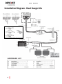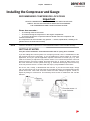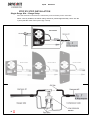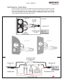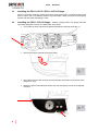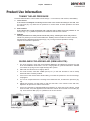
1
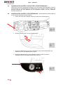
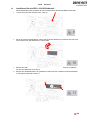
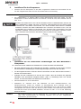
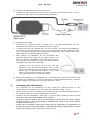
Unit 626 Kilshane Avenue, North West Business Park, Ballycoolin, Dublin 15, Ireland Telephone: +353 1 8612 632 Fax: +353 1 8612 647 email:[email protected] Web: www.driveriteair.com COMPRESSOR AND GAUGE KIT WITH LOW PRESSURE SENSOR / KIT COMPRESSEUR AVEC MANOMETRE ET LIMITEUR DE PRESSION / SET MIT MANOMETER, KOMPRESSOR UND NIEDERDRUCKSENSOR INSTALLATION INSTRUCTIONS / NOTICE DE MONTAGE / MONTAGEANLEITUNG Single Gauge kits / Manomètres Simple / Set mit Einzelmanometer DR.11.01 6110 DR.11.01 6113 DR.11.01 6114 DR.11.01 6120 Dual Gauge kits / Manomètres Doubles / Set mit Doppelmanometer DR.11.01 6112 DR.11.01 6115 DR.11.01 6121 18/14 Revision 1 Table of Contents / Table des matières / Inhalt English - Introduction .........................................................................4 IMPORTANT SAFETY NOTICE .................................................................................................. 4 Special Instructions for Air Connections ................................................................................ 4 Installation Diagram – Single Gauge Kits .............................................5 Installation Diagram - Dual Gauge kits ................................................6 Installing the Compressor and Gauge .................................................7 RECOMMENDED COMPRESSOR LOCATIONS ...................................................................................... 7 GETTING STARTED............................................................................................................................... 7 STEP BY STEP INSTALLATION............................................................................................................... 8 Single Gauge Kits – Gauge Setup .................................................................................................... 8 Dual Gauge Kits – Gauge Setup....................................................................................................... 9 1a. Installing the DR.11.016110 / DR.11.016113 Gauge ........................................................ 10 1b. Installing the DR.11.016114 Gauge................................................................................... 10 1c. Installing the DR.11.016120 Gauge................................................................................... 11 2. Installing the compressor unit. ............................................................................................. 12 3. Installing the electric wiring to the gauge / compressor. ..................................................... 12 4. Connecting the air tubing. .................................................................................................... 13 5. Connecting the wiring to the vehicle. ................................................................................... 14 6. System Check. ....................................................................................................................... 14 Product Use Information ..................................................................15 TUNING THE AIR PRESSURE ................................................................................................. 15 GUIDELINES FOR ADDING AIR (SEMI AIR KITS): ................................................................... 15 Français - Introduction......................................................................................................... 16 CONSIGNES DE SECURITE IMPORTANTES ............................................................................ 16 Instructions particulières pour les connectiques pneumatiques......................................... 16 SCHEMA ELECTRIQUE – MANOMÈTRE SIMPLE ..................................................................... 17 ........................................................................................................................................... 17 SCHEMA ELECTRIQUE – MANOMÈTRE DOUBLE .................................................................... 18 INSTALLATION DU COMPRESSEUR ET DU MANOMÈTRE ....................................................... 19 Emplacements recommandés pour le montage ............................................................................... 19 DEMARRAGE ..................................................................................................................................... 19 INSTALLATION ETAPE PAR ETAPE ..................................................................................................... 20 Montage du manomètre simple ................................................................................................... 20 2 15/14 Revision 1 Montage des kits manomètre double commande : ..................................................................... 21 1a. Montage du tableau de commande DR.11.016110 / DR.11.016113................................ 22 1b. Montage du tableau de commande DR.11.016114 .......................................................... 22 1c. Montage du tableau de commande DR.11.016120 .......................................................... 23 2. INSTALLATION DU COMPRESSEUR........................................................................................ 24 3. Installation du câblage électrique au tableau de commande............................................... 24 4. BRANCHEMENT DU TUBE PNEUMATIQUE............................................................................ 25 5. Branchement du câblage sur le véhicule .............................................................................. 26 6. Vérification du système ........................................................................................................ 26 INFORMATIONS RELATIVES A L’UTILISATION DU PRODUIT ................................................... 27 REGLAGE DE LA PRESSION ................................................................................................ 27 PRECONISATIONS DE MONTAGE (RENFORTS A AIR): ....................................................... 27 Deutsch - Einführung ........................................................................................................... 28 Wichtige Sicherheitshinweise .............................................................................................. 28 Hinweis zur Handhabung von Luftleitungen und Verbindungen......................................... 28 System-Schaltplan, Set mit Einzelmanometer ...................................................................... 29 System-Schaltplan, Set mit Doppelmanometer .................................................................... 30 Installation von Kompressor und Manometer ...................................................................... 31 Empfohlener Installationsort für den Kompressor ........................................................................... 31 SO FANGEN SIE AN ............................................................................................................................ 31 INSTALLATION SCHRITT FÜR SCHRITT ............................................................................................... 32 Einzelmanometer – Installation .................................................................................................... 32 Doppelmanometer - Installation................................................................................................... 33 1a. Installieren Sie das DR.11.016110 / DR.11.016113 Bedienteil – ...................................... 34 1b. Installieren Sie das DR.11.016114 Bedienteil ................................................................... 34 1c. Installieren Sie das DR.11.016120 Bedienteil ................................................................... 35 2. Installieren Sie den Kompressor. .......................................................................................... 36 3. Installieren Sie die elektrischen Verbindungen mit dem Manometer / Kompressor. .......... 36 4. Verbindung der Luftschläuche .............................................................................................. 37 5. Verbindung vom Kabelbaum und Fahrzeug.......................................................................... 38 6. Systemkontrolle .................................................................................................................... 38 Informationen zur Verwendung der Produkte ...................................................................... 39 Luftfederungen in der Praxis ................................................................................................ 39 Der richtige Luftdruck (Zusatzluftfederungen): ................................................................... 39 3 18/14 Revision 1 English - Introduction The purpose of this publication is to assist with the installation of the compressor and gauge system. It is important to read and understand the entire installation guide before beginning installation or performing any maintenance, service or repair. The information here includes a hardware list and step-by-step installation information. Drive-Rite reserves the right to make changes and improvements to its products and publications at any time. Contact Drive-Rite at +353 1 8612 632 or visit us online at www.driveriteair.com for the latest version of this manual. IMPORTANT SAFETY NOTICE The installation of this kit does not alter the Gross Vehicle Weight Rating (GVWR) or payload of the vehicle. Check your vehicle’s owner’s manual and do not exceed the maximum load listed for your vehicle. Gross Vehicle Weight Rating = the maximum allowable weight of the fully loaded vehicle (including passengers and cargo). This number — along with other weight limits, as well as tyre, rim size and inflation pressure data — is shown on the vehicle’s Safety Compliance Certification Label. Payload: The combined, maximum allowable weight of cargo and passengers that the truck is designed to carry. Payload is GVWR minus the Base Curb Weight. Precautions Never exceed the maximum and minimum recommended pressure limits: Minimum Pressure Maximum Pressure 1 Bar (14.5 p.s.i.) 7 Bar (100 p.s.i.) NEVER DRIVE WITH DEFLATED AIR SPRINGS Special Instructions for Air Connections • To cut the tubing correctly an appropriate tube cutter must be used (never scissors) • When inserting the tubing into the connection, it must be pushed in approximately 14mm until a ‘click’ is heard. To remove the tube, you must push the flange in on the connection and at the same time pull the tube. (No tool is necessary.) It is always advisable that LOCTITE or similar sealant be used on any threaded fittings. • • • 4 ATTENTION, when a tube is removed it is important to trim 14mm from the end before reconnection. 15/14 Revision 1 Installation Diagram – Single Gauge Kits DR.11.016110 Harness #2 HARDWARE LIST Item A B C D E F G Description................................Qty Compressor..................................1 Panel assembly............................1 Harness #1...................................1 Harness #2...................................1 Tube......................................3m (10’) Hardware pack.............................1 Hardware pack.............................1 5 18/14 Revision 1 Installation Diagram - Dual Gauge kits HARDWARE LIST Item A B C D E F 6 Description................................Qty Compressor..................................1 Panel assembly............................1 ‘Y’ assembly.................................1 Harness #1...................................1 Harness #2...................................1 Hose....................................7.5m(25’) Item G H I J K L Description................................Qty Grommet......................................1 Fuse.............................................1 Fuse.............................................1 Fuse Adapter...............................1 Red Wire...............................5m(16’) Black Wire............................2.5m(8’) 15/14 Revision 1 Installing the Compressor and Gauge RECOMMENDED COMPRESSOR LOCATIONS Important LOCATE COMPRESSOR IN DRY, PROTECTED AREA ON VEHICLE. DIRECT SPLASH OR EXCESSIVE MOISTURE CAN DAMAGE THE COMPRESSOR AND CAUSE SYSTEM FAILURE. Please also remember... • To avoid high heat environments • To avoid mounting the compressor in the engine compartment. • To check to be sure the compressor harness #2 will reach the compressor and connect to harness #1. The compressor can be mounted in any position — vertical, upside down, sideways, etc. (please refer to the instruction manual). NOTE Failure to install the compressor in a recommended location could void the warranty. GETTING STARTED This part of the installation should be done after the air spring kit is installed. If you are adding this control system to a coil-sprung semi-air, then no modifications to the low pressure sensor are necessary. If you are adding this control system to a Semi-Air application, and if your specific application requires a minimum of 0.6 bar (10 p.s.i.), then it will be necessary to adjust the low pressure sensor. To increase the pressure in the low pressure sensor, remove the rubber plug with pliers (fig. 2). Using an Allen wrench, turn the screw clockwise 4 and a quarter turns (fig. 3). Push the rubber plug back into the top of the low pressure sensor. Continue with the step by step installation instructions. Do not cut, trim, modify, or disassemble the harness. If you have excess length, simply coil it up and secure out of the way with the provided tie straps. All preassembled gauge panels have been 100% leak & function tested. DO NOT attempt to tighten, loosen, or adjust any fittings or connections. This will likely cause a leak or malfunction and void the warranty. 7 18/14 Revision 1 STEP BY STEP INSTALLATION Single Gauge Kits – Gauge Setup All of the electrical connections are matched by male-to-female push-in terminals. When correctly installed, the airline tubing should be pushed approximately 14mm into the T-piece past the collar of the t-piece (fig. 4 and 5). DR.11.016110 DR.11.016113 8 DR.11.016114 DR.11.016120 15/14 Revision 1 Dual Gauge Kits – Gauge Setup All of the electrical connections are matched by male-to-female push-in terminals. All of the air line connections will be white- to-white, no tape-to-no tape, indicated by the colour band. The colour band also serves as a reference point for installing the air line into the fitting. When correctly installed, the airline tubing should be pushed approximately 14mm into the T-piece past the collar of the t-piece (fig. 4 and 5). DR.11.016112 DR.11.016115 DR.11.016121 9 18/14 1a. Revision 1 Installing the DR.11.016110 / DR.11.016113 Gauge – Select a convenient mounting location that has a sturdy rigid surface. The bottom edge of the dash on either side of the steering wheel is a good location. Attach the panel to the selected location with the black self-tapping screws. 1b. 10 Installing the DR.11.016114 Gauge - Install the gauge panel. This gauge has been specifically designed to fit onto the dash board of the X250. • First locate the lower left shelf compartment beside the steering wheel (fig. 6). • Remove the shelf compartment from the dash. • Run Harness #1 and the air tubing through the dash board and connect them to the gauge as in fig 5. • Attach the panel to the selected location with the self-tapping screws in the marked locations. 15/14 1c. Revision 1 Installing the DR.11.016120 Gauge – This gauge has been specifically designed to fit onto the dash board of the X62. • First locate the top shelf compartment (fig. 9). • Using a flathead screwdriver, loosen the top latches in the shelf and pull it out. • Run Harness #1 and the air tubing through the dash board and connect them to the gauge as in fig 5. • Attach the panel to the selected location with the self-tapping screws. 11 18/14 2. Revision 1 Installing the compressor unit. • NOTE Hold the compressor in the recommended location and use the provided silver self-tapping screws to attach the mounting brackets to the vehicle. Attach the ground wire to one of the screws (fig. 1). • For box frames: In some cases the frame section will not be wide enough to mount the compressor legs flat to the rail. Refer to fig. 12 in this situation. DO NOT DRILL ANY HOLES INTO THE FRAME OR THE FLOOR BEFORE CHECKING FOR HYDRAULIC LINES, FUEL LINES, AND/OR ELECTRICAL WIRES THAT MAY NEED TO BE MOVED ASIDE. ALSO, WHEN ATTACHING TO THE FLOOR, IT IS IMPORTANT TO CHECK WHERE THE SCREWS PROTRUDE THROUGH THE FLOOR. IT MAY BE NECESSARY TO TRIM OR COVER THE TOP OF THE SCREWS INSIDE THE VEHICLE. A SEALER SHOULD BE USED AROUND THE SCREW TO PREVENT THE ELEMENTS FROM ENTERING THE CAB AREA. 3. Installing the electric wiring to the gauge / compressor. 3a. Connect wiring harness #1 to the back of the gauge panel. • With your thumb against the front side of the switch, connect the wire by pushing the female connectors onto the blade connectors on the switch. • On Dual Gauges kits match the white band on the air line to the white band on the tees. • Push the air tubing onto the “T” fitting until the air tubing completely covers the barb (fig. 4). Lubricating the air tubing will make it easier to push over the barb. Do not connect the power wire at this time. • NOTE 12 Wiring harness #1 also connects the gauge panel to the low pressure sensor assembly. The low pressure sensor protects the air springs from failure resulting from low pressure in the unloaded condition. The sensor is pre-set to maintain a MINIMUM pressure of 5 PSI in the air springs. The sensor measures the pressure in each spring and turns on the compressor if the pressure falls below 5 PSI. IMPORTANT: see fig. 2 & 3 for adjusting the minimum pressure. The low pressure sensor is preassembled onto wiring harness #1. The sensor should be located under the dash inside the vehicle and secured with the provided tie straps. 15/14 Revision 1 3b. Attach harness #2 to the compressor unit. • Push the air tubing completely over the barbed fitting on the compressor and connect the power wire (red) (fig. 13). 3c Route wiring harness #2 from the compressor. • Use existing grommets in the floor or firewall to route the harness from the compressor to the low pressure sensor. • In some cases, a hole may have to be drilled to allow access for the harness. Drill a 15mm (5/8”) diameter hole and install the provided grommet (fig. 14). It will be necessary to seal any grommets or holes that have been cut, drilled or removed so as not to allow elements to enter the cab area of the vehicle. • When routing wiring harness #2 from the compressor, avoid the exhaust pipe/silencer/catalytic convertor of the vehicle. Routing along the top of a cross member or over a heat shield is recommended. After the hole is drilled and before you route the harness through the firewall, insert the grommet and “walk” the material around the inside edge of the drilled hole. You may have to trim the grommet to get an exact fit. (The flexible grommet is in the sealed parts package.) 3d Connect the wiring harness #2 to wiring harness #1 inside the vehicle by connecting the red wire from harness #2 and the air tubing to the low pressure sensors. See fig. 5 for air tubing and electrical connection. 4. Connecting the air tubing. The next connection is between each air spring and the air tubing “T” fitting located just ahead of the check valves in harness #2, near the compressor (fig. 1 and 7). • With the air springs deflated, use a hose cutter to cut the air tubing already installed between the air springs and the inflation valves. • Install the provided “T” fittings (fig. 1) by pushing the air tubing into each leg of the “T” until you feel a definite “click”. • Connect a single length of air tubing to the open leg of each “T”. Bring each of the lines to the “T” fittings in harness #2 just in front of the check valves and connect as shown in fig. 7. • Route the air tubing across the chassis from the far side over the exhaust system heat shields and along the frame up to the compressor. Avoid heat sources, sharp edges and tight bends. 13 18/14 5. Revision 1 Connecting the wiring to the vehicle. 5a. Connect the power wire from harness #1. • Route it to the vehicle fuse box. • Use a multi meter to determine which open terminal (accessory, etc.) works only when the key is in the “on” or accessory position (or refer to the owner’s manual for an available accessory fuse). The terminal should have an amperage rating equal to or higher than the 15 amp in-line fuse. • Connection to the fuse terminal will depend on what type of fuse your vehicle uses. If your vehicle uses the barrel type fuse, use adapter #1. If you have the standard spade type fuses, use adapter #2. Many late model vehicles use a smaller spade type fuse which requires adapter #3 (see inset with fig. 1). If adapters #1 or #2 are used, it will be necessary to cut off the ¼” female connector attached to the power wire and crimp the smaller 3/16” female connector supplied with this kit. NOTE Connect adapter to “LIVE” side of the fuse (use a multi meter to determine). With the ignition on, the compressor will turn on and fill the system to 0.3 Bar (5 p.s.i.) before shutting off (or to 0.6 Bar (10 p.s.i. if you have modified the lower pressure sensor). 5b Connect the gauge light. • Route the white wire for the illuminated gauge to harness #1’s fused wire or to a dash light wire circuit and attach with the quick splice provided. • Ground the black wire to an adequate ground. Use the additional wire and connectors supplied if longer leads are needed (fig. 1). 6. System Check. • Press the off/on button to inflate both air springs and use the small deflate button to adjust the pressure. Inflate to 2 Bar (30 p.s.i.). Check all fittings and inflation valve cores with a soapy water solution to test for leaks. • Recheck air pressure after 24 hours. A slight loss after initial installation is normal. However if pressure has dropped more than 0.3 Bar (5 p.s.i.), re-test for leaks with soapy water solution. Please read and follow the maintenance and operating tips in the installation manual that came with your air spring kit. IMPORTANT: If the compressor runs continually or often, then there is a leak. Disconnect the compressor at the fuse box and test for leaks with a soapy water solution. NEVER RUN THE COMPRESSOR LONGER THAN FOUR MINUTES CONTINUOUSLY. ALLOW AT LEAST FIVE MINUTES FOR COOL DOWN BEFORE STARTING THE COMPRESSOR AGAIN 14 15/14 Revision 1 Product Use Information TUNING THE AIR PRESSURE Pressure determination comes down to three things — level vehicle, ride comfort, and stability. 1. Level vehicle If the vehicle’s headlights are shining into the trees or the vehicle is leaning to one side, then it is not level (fig. 15). Raise the air pressure to correct either of these problems and level the vehicle. 2. Ride comfort If the vehicle has a rough and harsh ride it may be due to either too much pressure or not enough (fig. 17). Try different pressures to determine the best ride comfort. 3. Stability Stability translates into safety and should be the priority, meaning the driver may need to sacrifice a perfectly level and comfortable ride. Stability issues include roll control, bounce, and dive during braking and sponginess (fig. 16). Tuning out these problems usually requires an increase in pressure. GUIDELINES FOR ADDING AIR (SEMI AIR KITS): 1. For all air systems, check the recommended Maximum and Minimum pressure for that kit in the Installation instructions. This is a rough guide for general information. NEVER over inflate air springs as this might damage the system. 2. Start with the vehicle level or slightly above. 3. For motor homes, start with 3-6Bar (45-90 p.s.i.) in the rear because it can be safely assumed that it is heavily loaded. 4. If the front of the vehicle dives while braking, increase the pressure in the front air bags, if equipped. 5. If it is ever suspected that the air bags have bottomed out, increase the pressure (fig. 18). 6. Adjust the pressure up and down to find the best ride. If the vehicle rocks and rolls, adjust the air pressure to reduce movement. 7. It may be necessary to maintain different pressures on each side of the vehicle. Loads such as water, fuel, and appliances will cause the vehicle to be heavier on one side (fig. 19). As much as a 3Bar (45 p.s.i.) difference is not uncommon. 15 18/14 Revision 1 Français - Introduction Le but de cette notice est de vous assister dans le montage du compresseur et du manomètre de contrôle. Il est important de lire et de comprendre les instructions avant de débuter l’installation ou de réaliser toute opération de SAV. Le présent document comprend la liste des pièces et le descriptif du montage étape par étape. Drive-Rite se réserve le droit d’apporter toute modification ou amélioration à ses produits et notices de montage à tout moment. N’hésitez pas à nous contacter pour obtenir la dernière version de cette notice. CONSIGNES DE SECURITE IMPORTANTES L’ajout d’un renfort pneumatique ne modifie pas le PTAC constructeur ni les charges maxi par essieu du véhicule. Vérifiez toujours le manuel constructeur de votre véhicule pour ne pas dépasser les charges maxi autorisées. PTAC = Poids total admissible en charge lorsque le véhicule est chargé (Poids du véhicule + charge y compris passagers) – Le PTAC autorisé est indiqué sur la plaque de tarage d’origine du véhicule Charge utile: Le poids total (charge et passagers compris) que le véhicule est autorisé à transporter. Précautions Ne jamais dépasser les pressions mini et maxi recommandées : Pression mini Pression maxi 1 Bar (14.5 p.s.i.) 7 Bars (100 p.s.i.) NE JAMAIS ROULER AVEC DES COUSSINS DEGONFLES Instructions particulières pour les connectiques pneumatiques • Utiliser un coupe tube (en aucun cas des ciseaux) pour couper les tubes à angle droit • • Pour insérer le tube dans les raccords, l’enfoncer d’environ 14 mm jusqu’à entendre un clic. Pour retirer le tube d’un raccord, pousser la collerette du raccord vers le corps du raccord tout en tirant le tube dans le sens opposé. Il est préconisé de toujours utilise du frein filet type LOCTITE sur les filetages afin d éviter les fuites. • • 16 ATTENTION, après avoir retirer le tube d’un raccord pneumatique, il est important de couper son extrémité sur une longueur de 14 mm environ avant de le reconnecter à nouveau. 15/14 Revision 1 SCHEMA ELECTRIQUE – MANOMÈTRE SIMPLE DR.11.016110 Harness #2 LISTE DE PIECES Réf A B C D E F G Description................................Qté Compresseur..................................1 Tableau de commande ...............1 Faisceau #1...................................1 Faisceau #2...................................1 Tuyaux.................................3m (10’) Lot petit matériel.............................1 Lot petit matériel.............................1 17 18/14 Revision 1 SCHEMA ELECTRIQUE – MANOMÈTRE DOUBLE HARDWARE LIST Item A B C D E F 18 Description................................Qty Compresseur..................................1 Tableau de commande..................1 ‘Y’ assembly...................................1 Faiseau #1.....................................1 Faiseau #2.....................................1 Tuyaux.................................7.5m(25’) Item G H I J K L Description................................Qty Passe-cable.................................1 Fusible..........................................1 Fusible..........................................1 Adapteur Fusible..........................1 Câble Rouge...........................5m(16’) Câble Noir…...........................2.5m(8’) 15/14 Revision 1 INSTALLATION DU COMPRESSEUR ET DU MANOMÈTRE Emplacements recommandés pour le montage Important INSTALLER LE COMPRESSEUR DANS UN ENDROIT SEC ET PROTEGE Des projections d’eau directes ou une humidité excessive peuvent endommager le compresseur et causer des dysfonctionnements. Recommendations diverses • Eviter les endroits trop exposés à la chaleur • Eviter de monter le compresseur dans le compartiment moteur • Vérifier que le faisceau #2 du compresseur est suffisamment long pour aller jusqu’au compresseur et être connecté au faisceau #1. Le compresseur peut être installé dans n’importe quelle position (vertical, tête en bas) – Se référer à la notice. NOTE Le non respect du choix d’un emplacement approprié peut annuler la garantie du produit. DEMARRAGE Cette partie du montage doit être réalisée après l’installation des coussins d’air. Si vous installez ce système de gestion sur un véhicule avec à ressorts hélicoïdaux d’origine, il n’est pas nécessaire de modifier le paramétrage du limiteur de pression. Si vous installez ce système en complément d’un kit semi air sur un véhicule à lames de ressort et si l’application nécessite une pression supérieure à 0.6 bar (10 psi), il sera nécessaire de régler les données du limiteur de pression. Pour augmenter la pression du limiteur, retirer le capuchon plastique avec des pinces (fig 2). Utiliser une clé Allen et visser dans le sens des aiguilles d’une montre 4 tours ¼ (fig 3). Remettre le capuchon en plastique en place et continuer de suivre la notice de montage. Ne pas couper, modifier ou désassembler le faisceau. Si celui est trop long, le rouler et le sécuriser au moyen des colliers fournis. Tous les tableaux de commande ont été testés au niveau du fonctionnement et des fuites éventuelles. Ne pas essayer de serrer, desserrer ou régler les raccords ou connectiques ; cela pourrait provoquer des fuites ou des disfonctionnements qui pourraient annuler la garantie. Retirer le capuchon en plastique Tourner 4 tours ¼ avec une clé Allen dans le sens des aiguilles d’une montre 19 18/14 Revision 1 INSTALLATION ETAPE PAR ETAPE Montage du manomètre simple Toutes les connections électriques sont réalisées avec des raccords male / femelle à prise rapide. Pour un montage correct, les tubes pneumatiques doivent rentrer d’environ 14 mm dans les raccords. (fig. 4 and 5). DR.11.016110 Masse Faisceau #1 Alimentation DR.11.016113 DR.11.016114 DR.11.016120 Tuyaux Faisceau #1 Faisceau #2 Côté compresseur Côté tableau de commande Capteur de pression Câble (rouge) 20 15/14 Revision 1 Montage des kits manomètre double commande : Tous les connections électriques sont réalisées avec des raccords male / femelle à prise rapide. Tous les raccords pneumatiques sont « blanc-à-blanc », et "pas-de-ruban à pas-deruban". Le ruban sert aussi d'un point de référence pour installer le tube pneumatique dans les raccords. Pour un montage correct, les tubes pneumatiques doivent rentrer d’environ 14 mm dans les raccords. (fig. 4 and 5). DR.11.016112 Faisceau #1 DR.11.016115 DR.11.016121 Faisceau #2 Faisceau #1 Côté compresseur Côté tableau de commande Câble (rouge) 21 18/14 1a. Revision 1 Montage du tableau de commande DR.11.016110 / DR.11.016113 Choisir un emplacement approprié avec une surface rigide et résistante. La partie inférieure du tableau de bord de chaque côté du volant est un bon emplacement. Fixer le tableau de commande sur la surface choisie avec les vis taraudées noires. 1b. Montage du tableau de commande DR.11.016114 – Ce tableau de commande est spécialement conçu pour être intégré dans le tableau de bord des véhicules X250 22 • Repérer le vide poche à gauche du volant (fig. 6). • Retirer le cache du tableau de bord. • Faire passer le faisceau #1 et le tube pneumatique dans le tableau de bord pour les relier au tableau de commande - fig 5. • Fixer le panneau de commande à l’emplacement sélectionné avec les vis taraudées. 15/14 1c. Revision 1 Montage du tableau de commande DR.11.016120 Ce tableau de commande est spécialement conçu pour être intégré dans le tableau du bord des véhicules X62 • Repérer le vide poche supérieur (fig. 9). • Avec un tournevis à tête plate, desserrer les loquets supérieurs du compartiment et le retirer. • Faire passer le faisceau #1 et le tube pneumatique dans le tableau de bord pour les relier au tableau de commande - fig 5. • Fixer le panneau de commande à l’emplacement sélectionné avec les vis taraudées 23 18/14 2. Revision 1 INSTALLATION DU COMPRESSEUR • NOTE Positionner le compresseur à l’endroit choisi et utiliser les vis taraudées fournies pour fixer les supports de compresseur sur le véhicule. Relier le fil de masse à l’une des vis (fig. 1). • Dans certains cas, le longeron du châssis ne sera pas assez large pour fixer les pattes de fixation du boitier compresseur bien à plat. Dans ce cas, se référer à la figure 12. NE PAS PERCER DE TROU DANS LE CHÂSSIS OU DANS LE PLANCHER AVANT D’ETRE SUR QU’IL N’Y A PAS DE CABLES ELECTRIQUES OU HYDRAULIQUES OU UNE ARRIVEE DE CARBURANT A DEPLACER. EN CAS DE FIXATION AU PLANCHER, IL EST IMPORTANT DE VERIFIER QUE LES VIS NE DEPASSENT PAS. IL PEUT ETRE NECESSAIRE DE LES COUPER ET DE D’ISOLER LES TROUS A L’INTERIEUR DU VEHICULE AVEC DU JOINT AFIN D’EVITER LES INFILTRATIONS DE L’EXTERIEUR.. CHASSIS PLANCHER PLATINE EN L Vis fournie avec support Des vis et écrous ¼ devront être fournis si besoin de fabriquer la platine en L 3. Installation du câblage électrique au tableau de commande 3a. Brancher le faisceau #1 à l’arrière du tableau de commande • En appuyant avec votre pouce sur le devant du tableau, connecter le câble en poussant les connecteurs femelles sur les connecteurs à lame du tableau. • Pour les kits avec manomètres doubles, voir que le ruban blanc sur le tube correspond au ruban blanc sur les tés. • Insérer le tube sur le raccord en té jusqu’à ce qu’il recouvre entièrement le laiton (fig. 4). Ne pas brancher le câble d’alimentation à ce moment de l’installation • NOTE 24 Le faisceau #1 relie également le tableau de commande au capteur de pression. Le capteur de basse pression protège les cousins en cas d’utilisation à une pression trop faible. Le capteur est pré-réglé pour maintenir une pression mini de 5 psi dans les coussins. Le capteur mesure la pression dans chacun des coussins et déclenche le compresseur si la pression descend en dessous de 5 psi. Voir Fig 2 & 3 pour ce règlement. Le capteur de pression est pré assemblé sur le faisceau #1. Il doit être monté sous le tableau de bord à l’intérieur du véhicule et fixé à l’aide des colliers fournis. 15/14 Revision 1 3b. Fixer le faisceau #2 sur le compresseur • Enfiler le tube sur le raccord laiton du compresseur et brancher le fil d’alimentation (rouge) (fig. 13). Tayaux Masse Faisceau # 2 Câble d’alimentation (rouge) Raccord compresseur 3c Router le faisceau #2 du compresseur • Utiliser les passe-câbles existants dans le plancher ou le pare-feu pour router le faisceau depuis le compresseur jusqu’au capteur de pression. • Dans certains cas, il sera nécessaire de percer un trou pour faire passer le faisceau. Percer un trou de 15mm (5/8”) de diamètre et fixer le passe câble (fig. 14). Il faudra ensuite protéger tous les passe-câbles et tous les trous réalisés afin d’éviter tous risques d’infiltration dans le véhicule. • Attention à ce que le faisceau #2 ne passe pas trop près des conduits d’échappement du véhicule. En cas de risque, le protéger avec une plaque de protection anti chaleur. Après avoir percé le trou et avant de faire passer le câblage, insérer le passe câble et le fixer à l’intérieur du trou. Il faudra peut être le réduire pour l’adapter à la taille du trou. (le passe câble flexible est livré dans le sachet scellé) 3d Brancher le faisceau #2 sur le faisceau #1 à l’intérieur du véhicule en reliant le câble rouge du faisceau #2 et le tube d’air au capteur de pression. Voir fig. 5 pour les branchements électriques et pneumatiques. 4. BRANCHEMENT DU TUBE PNEUMATIQUE Le branchement suivant est à réaliser entre les 2 coussins et le raccord en té juste devant les valves de sécurité du faisceau #2, proche du compresseur (fig. 1 and 7). • Les cousins dégonflés, utiliser un coupe tube pour couper le tube déjà installé entre les cousins et les valves de gonflage. • Installer le raccord en té (fig. 1) fourni en poussant le tube dans chaque embout du raccord en té jusqu’à entendre un clic. • Relier une longueur de tube sur l’embout encore disponible du raccord. Ramener chacun des tubes vers les raccords en T du faisceau #2 juste devant les valves de sécurité et brancher comme indiqué fig. 7. • Router les tubes à travers le châssis depuis l’arrière du véhicule le long du longeron jusqu’au compresseur en les protégeant de toute source de chaleur et de tous bords tranchants en évitant de les plier. 25 18/14 5. Revision 1 Branchement du câblage sur le véhicule 5a. Brancher le câble d’alimentation du faisceau #1. • Le router vers la boite à fusibles. • Utiliser un multimètre pour déterminer une borne disponible fonctionnant uniquement quand la clé est sur ON (ou se référer au guide de l’utilisateur pour déterminer une borne accessoires disponible) La borne de connexion doit avoir un ampérage au moins égal ou supérieur au fusible 15 AMP. • La connexion à la boîte à fusible dépend du type de fusibles utilisés sur votre véhicule. Si votre véhicule est équipé de fusibles ronds, utiliser l’adaptateur #1. Si vous avez des fusibles standard à languettes, utiliser l’adaptateur #2. La plupart des véhicules récents sont équipés de fusibles standard à languettes plus petits pour lesquels il faudra utiliser l’adaptateur #3 (Voir fig. 1). Si vous utilisez les adaptateurs #1 ou #2, il faut alors couper la prise femelle¼” attachée au câble d’alimentation et la remplacer par la prise femelle plus petite 3/16” fournie avec le kit. NOTE Brancher l’adaptateur sur le côté « LIVE » du fusible (utiliser un multimètre pour vérifier). En démarrant le contact, le compresseur se mettra à tourner pour remplir le système jusqu’à 0.3 bars (ou 0.6 bars si vous l’avez ajusté) avant de s’arrêter. 5b Brancher l’éclairage du panneau de commande • Amener le câble blanc pour l’éclairage du tableau de commande jusqu’au câble relié au fusible du faisceau #1 ou jusqu’au câble d’éclairage du tableau de bord et le relier avec l’épissure fournie. • Relier le fil noir à la masse. Utiliser le câblage et les raccords fournis si vous avez besoin d’une plus grande longueur. 6. Vérification du système • Appuyer sur le bouton ON/OFF pour gonfler les 2 coussins et utiliser la petite valve de purge pour ajuster la pression dans les cousins. Gonfler à 2 bars (30 psi). Vérifier qu’il n’y ait pas de fuite au niveau des raccords et des valves à l’aide d’eau savonneuse. • Vérifier une nouvelle fois après 24 heures. Une légère perte de pression après le montage est normale. Cependant, si la pression a chuté de plus de 0.3 bars (5 psi) vérifier à nouveau les fuites éventuelles au niveau des raccords. Lisez attentivement le manuel d’utilisation livré avec le renfort pneumatique. IMPORTANT: Si le compresseur tourne tout le temps ou souvent, c’est qu’il y a une fuite dans le système. Débrancher le compresseur dans la boite à fusibles et vérifier les fuites éventuelles avec de l’eau savonneuse. NE JAMAIS FAIRE TOURNER LE COMPRESSEUR PLUS DE 4 MINUTES D’AFFILEE. LE FAIRE REFROIDIR AU MOINS 5 MN AVANT DE LE REFAIRE FONCTIONNER. 26 15/14 Revision 1 INFORMATIONS RELATIVES A L’UTILISATION DU PRODUIT REGLAGE DE LA PRESSION Le niveau de pression dans les coussins dépend de 3 facteurs : la hauteur du véhicule, le confort de roulage et la tenue de route. 1. Hauteur du véhicule Si les feux du véhicule éclairent les cimes des arbres ou qu’il penche d’un côté, c’est qu’il n’est pas de niveau (figure 15) Augmenter la pression d’air dans les coussins pour corriger l’un ou l’autre de ces problèmes et remettre le véhicule à niveau. 2. Confort de roulage Si le véhicule n’est pas confortable lors de la conduite, soit les coussins sont trop gonflés soit au contraire ils ne sont pas assez gonflés (fig. 17). Essayez de gonfler à des pressions différentes pour trouver la pression la mieux appropriée pour un confort optimisé. 3. Tenue de route La stabilité est synonyme de sécurité et devrait être une priorité qui passe avant le confort et la mise à niveau. La problématique de la tenue de route concerne le roulis, les rebonds, l’excès de souplesse et la tenue de route du véhicule lors du freinage (fig. 16). Pour résoudre ces problèmes, if s’agit souvent d’augmenter la pression dans les coussins. PRECONISATIONS DE MONTAGE (RENFORTS A AIR): 8. Vérifier les pressions mini et maxi à respecter préconisées pour votre renfort pneumatique dans le manuel d’utilisation. Ne JAMAIS gonfler les coussins au dessus de la pression maxi préconisée sous peine d’endommager le système. 9. Commencer en mettant le véhicule à sa hauteur d’origine ou un peu au dessus. 10. Pour les camping-cars, commencer à gonfler entre 3 et 6 bars (40 – 90 psi) à l’arrière car ces véhicules sont de nature très chargés. 11. Si l’avant du véhicule a tendance à plonger lors du freinage, augmenter la pression dans les coussins à l’avant si le véhicule est équipé. 12. Si les coussins ont tendance à talonner, augmenter la pression (fig. 18). 13. N’hésitez pas à gonfler et dégonfler pour trouver le meilleur réglage et donc le meilleur confort pour votre véhicule. Si votre véhicule est sujet aux rebonds ou au roulis, régler la pression pour réduire ces effets. 14. Il peut être dans certains cas nécessaire de gonfler les coussins à des pressions différentes pour corriger l’assiette arrière droite / gauche et compenser le poids des réservoirs d’eau ou de carburants par exemple (fig. 19). Un écart de pression de 3 bars entre les 2 coussins n’est pas rare. 27 18/14 Revision 1 Deutsch - Einführung Diese Montageanleitung dient der Montage/Installation eines System mit Manometer und Kompressor. Bitte lesen Sie diese Anleitung sorgfältig und vergewissern Sie sich, dass Sie alles verstanden haben, bevor Sie mit der Montage beginnen. Drive-Rite behält sich Änderungen im Zuge der Produktbeobachtung und weiterentwicklung zu jeder Zeit vor. Für Informationen zu Neuerungen besuchen Sie unsere Homepage www.driveriteair.com oder rufen Sie uns an: Hotline +353 1 8612 632. Wichtige Sicherheitshinweise Die Montage dieser Zusatzluftfeder ändert bei Ihrem Fahrzeug weder die maximal zul. Gesamtmasse noch die Zuladung. Beachten Sie weiterhin die Bedienungs- und Gebrauchsanleitungen des Herstellers und halten Sie sich an die vom Hersteller freigegebenen max. zulässigen Gewichte und an alle Vorgaben. Zul. Gesamtgewicht (zGG) = das Fahrzeuggewicht im Fahrzustand oder zu jedem Zeitpunkt der Fahrt, also inkl. Fahrer, Passagiere, Betriebsmittel und Fracht/Beladung. Das zGG ist nur eine von zahlreichen maximalen Werten, die an einem Fahrzeug beachtet und eingehalten werden müssen. Andere Werte, die Sie zwingend beachten müssen, sind die Reifentraglast oder die maximal zulässigen Achslasten. Die Richtwerte finden Sie in Ihren Zulassungs- und Fahrzeugpapieren. Zuladung: Die maximal zulässige Gesamtmasse minus des tatsächlichen FahrzeugEigengewichts im fahrbereiten Zustand ergibt die erlaubte Zuladung. Beachten Sie zudem zu jeder Zeit die Angeben, Hinweise und Richtlinien des Fahrzeugherstellers. Weitere wichtige Informationen: Achten Sie sich immer darauf, dass die min./max. Luftdrücke im System eingehalten werden! Mindestdruck Maximaldruck 1 Bar (14,5 p.s.i) 7 Bar (100 p.s.i.) Fahren Sie niemals mit leeren Luftbälgen! Hinweis zur Handhabung von Luftleitungen und Verbindungen • Zum Kürzen von Kunststoff-Luftleitungen benutzen Sie bitte ausschließlich einen Schlauchschneider und niemals einen Seitenschneider oder eine Schere. • Wenn Sie die korrekt gekürzte Luftleitung in einen Verbinder stecken, achten Sie bitte darauf, dass die Luftleitung ca. 14 mm in den Anschluss hingedrückt wird, bis ein Klick spürbar ist. Sie benötigen kein Werkzeug, um den Schlauch aus dem Verbindungsstück zu ziehen Stattdessen drücken Sie den Flansch des Verbindungsstückes nach innen und ziehen die Luftleitung heraus. Für die Montage von Gewindeluftleitungen empfehlen wir immer LOCTITE oder andere Dichtmittel. • • ACHTUNG! Wird eine Luftleitung ein weiteres Mal verwendet, muss das Ende des Luftschlauchs um mind. 14 mm und zudem sehr akurat gekürzt werden, um Leckagen zu vermeiden. 28 15/14 Revision 1 System-Schaltplan, Set mit Einzelmanometer DR.11.016110 Harness #2 STÜCKLISTE Item A B C D E F G Description...........................Menge Kompressor..................................1 Einbaubedienteil...........................1 Kabelbaum #1..............................1 Kabelbaum #2..............................1 Luftleitung....................................3m Hardware-Paket...........................1 Hardware-Paket...........................1 29 18/14 Revision 1 System-Schaltplan, Set mit Doppelmanometer STÜCKLISTE A B C D E F 30 Beschreibung..........................Menge Kompressor..................................1 Manometer...................................1 ‘Y’ Stück.......................................1 Kabelbaum #1..............................1 Kabelbaum #2..............................1 Luftleitung.................................7.5 m G H I J K L Beschreibung..........................Menge Tülle..............................................1 Sicherung......................................1 Sicherung......................................1 Sicherungsadapter........................1 Rotes Kabel...............................5 m Schwarzes Kabel.......................2,5 15/14 Revision 1 Installation von Kompressor und Manometer Empfohlener Installationsort für den Kompressor Wichtig: Bauen Sie den Kompressor an einem trockenen, geschützten Platz im Fahrzeug ein. Direkt auftreffendes Spritzwasser und starke Verschmutzung können den Kompressor schädigen und zu Systemversagen führen. Bitte beachten Sie auch, dass... • Sie den Kompressor nicht in heißer Umgebung montieren sollten (z.B. Auspuff). • Sie den Kompressor nicht im Motorbereich montieren sollten. • Sie den Kompressor montieren, so dass Kabelbaum #2 mit dem Kompressor verbunden ist und auch mit Kabelbaum #1. Der Kompressor kann in jeder Position montiert werden, vertikel und horizontal oder auch auf dem Kopf stehend. Bitte schauen Sie sich hierzu die Montageanleitung an. HINWEIS Die fehlerhafte Installation des Kompressors bzw. die Montage an einem falschen Platz kann zum Verlust der Gewährleistung führen. SO FANGEN SIE AN Nach dem Einbau der Luftfedern sollens Sie mit diesem Teil der Montage weitermachen: Wenn Sie dieses Kontrollsystem mit Zusatzluftfedern bei Schraubenfederung verbinden, dann ist keine Änderung am Niederdrucksensor notwendig. Wenn Sie es in einem Zusatzluftfedersystem bei Blattfederung verwenden und Ihre spezielle Anwendung einen Minimaldruck von etwa 0,6 bar erfordert, dann müssen Sie den Niederdrucksensor auf diesen Wert einstellen. Um den Druck im Sensor zu erhöhen, entfernen Sie die Gummiabdeckung mit einer Zange (Skizze 2). Mit einem Innensechskant drehen Sie die nun sichtbare Schraube vier und einviertal Umdrehungen im Uhrzeigersinn (Skizze 3). Den Gummideckel wieder aufsetzen. Fahren Sie nun mit der Montage fort. Kürzen, ändern oder zerlegen Sie den Kabelbaum niemals! Wenn Sie Überlängen haben, so wickeln Sie die Kabel bitte einfach auf und sichern sie mit den mitgelieferten Kabelbindern. Alle vormontierten Manometer-Teile sind zu 100 % auf Dichtigkeit und Funktion getestet. Versuchen Sie NICHT, etwas an den vormontierten Teilen oder Verbindungen zu lösen oder Schraubverbindungen stärker anzuziehen. Dies könnte zu Beschädigungen führen und einen Verlust der Gewährleistung nach sich ziehen. 31 15/14 Revision 1 INSTALLATION SCHRITT FÜR SCHRITT Einzelmanometer – Installation Die elektrische Verbindungen haben männliche und weibliche Anschlussstecker. Richtig montiert, die Luftverbindung soll ca. 14 mm in das T-Stück hingedrückt wird. DR.11.016110 DR.11.016113 32 DR.11.016114 DR.11.016120 15/14 Revision 1 Doppelmanometer - Installation Das rechte Manometer wird mit einem weissen Band gekennzeichnet. Verbinden Sie diese Seite nun mit der Luftleitung, die ebenfalls weiss markiert ist. Richtig montiert, liegt vordere Kante des Bands direkt neben dem Flansch des Verbindungsstücks. (Abb. 4,5). DR.11.016112 DR.11.016115 DR.11.016121 33 15/14 1a. Revision 1 Installieren Sie das DR.11.016110 / DR.11.016113 Bedienteil – Wählen Sie dazu einen geeigneten Montageort, der eine robuste, feste Oberfläche aufweist. Die Unterkante des Armaturenbretts auf beiden Seiten des Lenkrads ist dafür meistens gut geeignet. Bringen Sie das Bedienteil an der gewählten Position mit den schwarzen Schneidschrauben an. 1b. Installieren Sie das DR.11.016114 Bedienteil - Dieses Bedienteil wurde spezifisch für das Armaturenbrett des X250 entwickelt. 34 • Finden Sie zuerst das niedrigere linke Fach neben dem Lenkrad (Abb 6). • Entfernen Sie das Fach von dem Armaturenbrett. • Bringen Sie Kabelbaum #1 und den Luftschlauch durch das Armaturenbrett und verbinden Sie sie zum Bedienteil wie in Abb 5. • Bringen Sie das Bedienteil an der gewählten Position mit den schwarzen Schneidschrauben in den gekennzeichneten Orten an. 15/14 1c. Revision 1 Installieren Sie das DR.11.016120 Bedienteil – Dieses Bedienteil wurde spezifisch für das Armaturenbrett des Renault Master entwickelt. • Finden Sie zuerst das obersten Fach. (Abb 9). • Mit einem Flachschraubendreher, lassen Sie die oberen Rasten frei. Entfernen Sie das Fach, und montieren Sie das Bedienteil in seinem Platz. • Bringen Sie Kabelbaum #1 und den Luftschlauch durch das Armaturenbrett und verbinden Sie sie zum Bedienteil wie in Abb 5. • Bringen Sie das Bedienteil an der gewählten Position mit den schwarzen Schneidschrauben in den gekennzeichneten Orten an. 35 15/14 2. Revision 1 Installieren Sie den Kompressor. • HINWEIS • Plazieren Sie den Kompressor an der dafür vorgesehenen Stelle und verschrauben Sie ihn mit dem mitgelieferten Halter und den Schneidschrauben am Fahrzeug. Verbinden Sie das Erdungskabel mit einer der Schrauben (Abb. 1). Für Kastenrahmen: In einigen Fällen ist das Rahmenprofil nicht breit genug, um den Kompressor-Fuß flach auf die Schiene zu montieren. Ist das der Fall, dann schauen Sie sich Abb. 12 an. BOHREN SIE NIEMALS EIN LOCH IN DEN RAHMEN ODER FAHRZEUGBODEN, BEVOR SIE NICHT ÜBERPRÜFT HABEN, OB DORT HYDRAULIK- UND BRENNSTOFFLEITUNGEN ODER ELEKTRISCHE LEITUNGEN VERLAUFEN, DIE BEIM BOHREN BESCHÄDIGT WERDEN KÖNNTEN. PRÜFEN SIE BEIM ANBRINGEN DES HALTERS AM BODEN AUCH, WO DIE SCHRAUBEN IM FAHRZEUG AUSTRETEN. DIE SPITZEN DER SCHRAUBEN SOLLTEN GEKÜRZT WERDEN. AUCH MUSS DIE EINTRITTSSTELLE VERSIEGELT WERDEN, DAMIT NICHT WASSER UND SCHMUTZ INS INNERE DES FAHRZEUGS GELANGEN. 3. Installieren Sie die elektrischen Verbindungen mit dem Manometer / Kompressor. 3a. Verbinden Sie den elektrischen Kabelbaum #1 mit der Rückseite des Bedienteils. • Mit Ihrem Daumen gegen die Vorderseite des Schalters, verbinden Sie die Leitung. Drücken Sie die weiblichen Verbindungen auf die klingenförmigen Stecker auf dem Schalter. • Für die Doppelmanometer, verbinden Sie den Luftschlauch mit dem weissen Band mit dem TStücken mit weissem Band. • Schieben Sie den Luftschlauch so weit auf das T-Stück, dass der Schlauch die gezackte Oberfläche des Anschlusses komplett bedeckt. (Abb. 4). Seifenlauge kann hier benutzt werden, um das Aufschieben des Schlauchs zu erleichtern. • Das Stromkabel noch nicht anschließen. • Kabelbaum #1 verbindet auch das Bedienteil mit dem Niederdrucksensor. Der Niederdrucksensor schützt die Luftfeder vor Beschädigung durch niedrigen Druck im unbeladenen Zustand. Der Sensor ist auf einen Minimaldruck von 0,3 bar (5 psi) im Luftbalg voreingestellt. Der Sensor misst den Druck in jeder Luftfeder und startet den Kompressor, wenn der Druck unter 0,3 bar abfällt. HINWEIS: Achauen sie abb. 2 & 3 für die Einstelung desminimaldrucks. HINWEIS Der Niederdrucksensor wird auf Kabelbaum Nr. 1 vormontiert. Der Sensor sollte sich unter dem Armaturenbrett im Fahrzeug befinden und mit den mitgelieferten Kabelbindern gesichert werden. 36 15/14 Revision 1 3b. Verbinden Sie Kabelbaum #2 mit dem Kompressor. • Schieben Sie die Luftleitung komplett über den Anschluss am Kompressor (Abb. 13) und verbinden Sie dann das rote Stromkabel mit dem Kabelbaum. 3c Kabelbaum #2 verlegen. • Verwenden Sie vorhandene Ösen im Boden oder in der Brandschutzschicht, um den Kabelbaum vom Kompressor zum Niederdrucksensor zu führen. • In einigen Fällen kann es notwendig sein, ein Loch zu bohren, um Raum für den Kabelbaum zu schaffen. Bohren Sie dann ein 15-mm-Loch und verwenden Sie die mitgelieferte Tülle (Abb. 14). Bitte versiegeln Sie anschließend sämtliche Bohrungen oder andere Löcher, damit weder Schmutz noch Wasser eindringen können. • Beim Verlegen von Kabelbaum #2 vom Kompressor bitte unbedingt darauf achten, dass Sie die Kabel niemals in der Nähe von Auspuff, Schalldämpfer oder Katalysator verlegen. Wir empfehlen eine Verlegung entlang der Oberseite eines Querträgers oder über einem Hitzeschild. Nachdem das Loch gebohrt ist und bevor Sie den Kabelbaum durch die Brandschutzschicht führen, sollten Sie die Tülle einpassen und das Material um die Bohrung kleiden (Abb. 8). Möglicherweise müssen Sie die Tülle kürzen, um eine perfekte Passform zu erhalten. (Die Tülle befindet sich im versiegelten Paket.) 3d Bringen Sie Kabelbaum # 2 mit Kabelbaum # 1 im Fahrzeuginnern zusammen, indem Sie das rote Kabel von Kabelbaum # 2 und die Luftleitungen mit dem Niederdrucksensor verbinden. Wegen Luftleitung und elektrischem Anschluss siehe auch Abb. 5. 4. Verbindung der Luftschläuche Nun verbinden Sie die Luftfederung mit dem T-Stück der Luftleitung direkt vor dem Rückschlagventil in Kabelbaum #2, in der Nähe des Kompressors (Abb. 1 and 7). • Lassen Sie die Luft aus den Luftbälgen ab und verwenden Sie einen Schlauchabschneider, um die Luftleitung zwischen Luftfeder und Befüllventil zu kürzen. • Installieren Sie das mitgelieferte T-Stück (Abb. 1), indem Sie die Luftleitung so tief ins T-Stück einschieben, bis sie mit einem fühlbaren “Klick” einrastet. • Verbinden sie für jede Seite ein Stück vom Luftschlauch mit einem Bein des T-Stuck. Bringen Sie jedes Schlauch zu den T-Verbindungen in Kabelbaum #2, gerade vorne von den Ventilen. Verbinden Sie wie im Abb. 13 • Verlegen Sie die Luftleitung entlang des Chassis über den Hitzeschutz der Abgasanlage und entlang des Rahmens bis zum Kompressor. Vermeiden Sie Kontakt zu Wärmequellen, scharfen Kanten und verlegen Sie die Leitung nicht in engen Kurven. 37 15/14 5. Revision 1 Verbindung vom Kabelbaum und Fahrzeug 5a. Schließen Sie das Stromkabel von Kabelbaum #1 an. • Verlegen Sie es zum Sicherungskasten des Fahrzeugs. • Verwenden Sie ein Vielfachmessgerät (Multimeter), um herauszufinden, welche offenen Terminals (Zubehör etc.) es gibt, die nur mit “Zündung an” (Stufe 1) oder Stufe 2 funktionieren (eventuell finden Sie diese Information auch im Benutzerhandbuch Ihres Fahrzeugs). Das Terminal sollte mindestens 15 Ampere Stromstärke aufweisen. • Die Verbindung zum Sicherungskasten hängt vom Sicherungstyp ab, der in Ihrem Fahrzeug verwendet wird. Siehe Abb. 1. Wenn die Adapter #1 oder #2 verwendet werden, ist es erforderlich, den ¼”-Kabelschuh wegzunehmen und dafür den 3/16”-Kabelschuh zu verwenden, der mit diesem Kit geliefert wird. HINWEIS Stellen Sie die Verbindung zum Sicherungskasten her. Bei eingeschalteter Zündung wird der Kompressor aktiviert. Er befüllt das System mit 0,3 bar (oder einem höheren Wert, falls Sie diesen vorher am Niederdrucksensor eingestellt haben). 5b Das Lichtkabel des Manometers anschließen. • Führen Sie das weiße Beleuchtungskabel zu dem abgesicherten Kabel in Kabelbaum #1 oder zu einem Kabel, das Licht für das Armaturenbrett liefert. • Erden Sie das schwarze Kabel. Benützen Sie zusätzliches Kabel und Verbindungsteile, falls erforderlich (Abb. 1). 6. Systemkontrolle • Drücken Sie den An/Aus-Schalter, um beide Bälge mit Luft zu befüllen und passen Sie den Luftdruck mit dem kleinen Ablassschalter an. Pumpen Sie auf 2 bar (30 p.s.i.) auf. Überprüfen Sie sämtliche Verbindungen und auch die Rückschlagventile mit einer Seifenlösung auf Dichtigkeit, um Leckagen zu finden. • Überprüfen Sie den Luftdruck nach 24 Stunden noch einmal. Ein leichter Luftverlust nach der Erstmontage ist normal. Sollte der Luftdruck jedoch um mehr als 0,3 bar (5 p.s.i.) gefallen sein, so testen Sie die Dichtigkeit des Systems nochmals mit Seifenlösung. Bitte lesen und befolgen Sie die Wartungs- und Bedienhinweise in der Bedienungsanleitung, die mit Ihrer Luftfederung geliefert wurde. WICHTIG: Wenn der Kompressor sehr lange und andauernd läuft, dann gibt es eine Undichtigkeit im System. Ziehen Sie die Kompressorsicherung am Sicherungskasten und überprüfen Sie alle Anschlüsse mit einer Seifenlösung. LASSEN SIE DEN KOMPRESSOR NIEMALS MEHR ALS VIER MINUTEN LANG OHNE UNTERBRECHUNG LAUFEN. LASSEN SIE DEN KOMPRESSOR MINDESTENS FÜNF MINUTEN ABKÜHLEN, BEVOR SIE IHN DANN WIEDER BENUTZEN. 38 15/14 Revision 1 Informationen zur Verwendung der Produkte Luftfederungen in der Praxis Der richtige Luftdruck hängt von drei Dingen ab: Fahrniveau, Fahrkomfort und Stabilität. 1. Fahrniveau Wenn das Fahrzeug hinten stark nach unten hängt, die Scheinwerfer also Richtung Himmel strahlen, oder wenn das Fahrzeug zu einer Seite hängt, dann ist eine Korrektur der Fahrstellung notwendig (Bild 15). Erhöhen Sie den Luftdruck in einem oder in beiden Bälgen, um die Fehlstellungen zu beseitigen. 2. Fahrkomfort Wenn das Fahrzeug sich sehr hart fährt und Fahrbahnstöße ungefiltert auf Fahrer, Fahrzeug und Ladung wirken können, dann ist der Luftdruck zu hoch oder zu niedrig (Bild 17). Verwenden Sie verschiedene Luftdruckwerte, bis Sie den Komfort haben, den Sie sich wünschen. 3. Stabilität Stabilität garantiert Fahrsicherheit und sollte deshalb Vorrang haben vor Fahrzeugposition oder Komfort (fig. 16). Der richtige Luftdruck (Zusatzluftfederungen): 1. Bitte schauen Sie unbedingt zunächst, wie hoch der Minimal- und der Maximaldruck im von Ihnen verwendeten System sein darf. Die Angaben finden Sie in der Montageanleitung und in der Bedienungsanleitung. Dies sind Richtwerte, die für spezielle Einsatzzwecke variiert werden können. Überschreiten Sie jedoch niemals den Maximaldruck im System, denn dies könnte zu einem Versagen und zur Zerstörung des Systems führen. 2. Achten Sie darauf, dass bei gefülltem Luftsystem das normale Fahrzeugniveau erreicht wird oder ein minimal höheres Niveau. 3. Bei Wohnmobilen (Reisemobilen) starten Sie mit einem Wert zwischen 3-6 bar (45-90 p.s.i.) in den Luftbälgen. Wohnmobile sind in aller Regel hinten sehr stark mit Gewicht belastet. 4. Taucht die Fahrzeugfront beim Bremsen stark ein, so erhöhen Sie bitte den Luftdruck in den vorderen Luftbälgen, falls vorhanden. 5. Falls Sie das Gefühl haben, dass die Luftbälge durchschlagen, so sollten Sie den Luftdruck erhöhen (Bild 18). 6. Nehmen Sie sich Zeit und variieren Sie den Luftdruck, um das beste Fahrgefühl zu bekommen. Falls das Fahrzeug stark schwankt, so passen Sie den Luftdruck an, bis die Bewegungen nachlassen. 7. Es kann notwendig sein, auf den beiden Fahrzeugseiten mit unterschiedlichem Luftdruck zu fahren, um Ungleichgewichte auszugleichen (Bild 19). Bis zu 3 bar (45 p.s.i.) Unterschied auf beiden Seiten sind in Ordnung. 39 15/14 Revision 1 Unit 626 Kilshane Avenue, North West Business Park, Ballycoolin, Dublin 15, Ireland Telephone: +353 1 8612 632 Fax: +353 1 8612 647 email:[email protected] Web: www.driveriteair.com 40